
В последнее время всё чаще появляются посты о приобретении мануалов по ремонту СГВ. Задался и я вопросом найти такое руководство, но в электронном виде. И нашёл. Обращаюсь к админам: Это не реклама, это реальная помощь всему братству сузуководов. У многих нет этакой книги, а приобрести нет возможности. Выкладываю ссылку на данное руководство, правда в черно-белом варианте.
docviewer.yandex.ru/?url=…jvu&page=1&c=580792b0eeb7
Можно скачать цветной вариант. Заходите по ссылке и сохраняйте в комп.
vk.com/doc-113732762_4372…423&dl=bb58be513eb3ad9ab8
Войдите или зарегистрируйтесь, чтобы писать комментарии, задавать вопросы и участвовать в обсуждении.
Все комментарии
Сборник руководств на английском языке по техническому обслуживанию и ремонту автомобиля Suzuki Grand Vitara серии JB с 2005 года выпуска.
- Автор: —
- Издательство: Suzuki Motor Corporation
- Год издания: —
- Страниц: —
- Формат: PDF
- Размер: 190,8 Mb

Сборник руководств на английском, немецком, французском и испанском языках по техническому обслуживанию и ремонту автомобилей Suzuki Grand Vitara серии SQ и Suzuki Grand Vitara XL-7 серии JA с 1997 года выпуска.
- Автор: —
- Издательство: Suzuki Motor Corporation
- Год издания: —
- Страниц: —
- Формат: PDF
- Размер: 800,5 Mb
Мультимедийное руководство на 11 языках по техническому обслуживанию и ремонту автомобиля Suzuki Grand Vitara второго поколения.
- Автор: —
- Издательство: —
- Год издания: —
- Страниц: —
- Формат: MDF
- Размер: 149,5 Mb
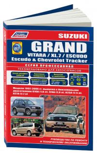
Руководство по эксплуатации, техническому обслуживанию и ремонту + каталог расходных запчастей автомобилей Chevrolet Tracker и Suzuki Escudo/Grand Escudo/Grand Vitara/Grand Vitara XL-7 1997-2006 годов выпуска с бензиновыми двигателями.
- Автор: —
- Издательство: Легион-Автодата
- Год издания: —
- Страниц: 534
- Формат: —
- Размер: —
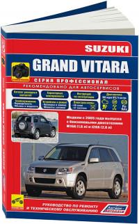
Руководство по эксплуатации, техническому обслуживанию и ремонту + каталог расходных запчастей автомобиля Suzuki Grand Vitara с 2005 года выпуска с бензиновыми двигателями объемом 1,6/2,0 л.
- Автор: —
- Издательство: Легион-Автодата
- Год издания: —
- Страниц: 446
- Формат: —
- Размер: —
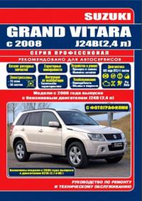
Руководство по эксплуатации, техническому обслуживанию и ремонту + каталог расходных запчастей автомобиля Suzuki Grand Vitara с 2008 года выпуска с бензиновым двигателем объемом 2,4 л.
- Автор: —
- Издательство: Легион-Автодата
- Год издания: 2015
- Страниц: 569
- Формат: —
- Размер: —
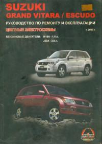
Руководство по эксплуатации и ремонту автомобилей Suzuki Grand Vitara и Suzuki Escudo с 2005 года выпуска с бензиновыми двигателями объемом 1,6/2,0 л.
- Автор: —
- Издательство: Монолит
- Год издания: 2009
- Страниц: 386
- Формат: DjVu
- Размер: 12,3 Mb

Руководство по эксплуатации и ремонту автомобилей Suzuki Grand Vitara и Suzuki Escudo с 2005 года выпуска с бензиновыми двигателями объемом 1,6/2,0/2,4/3,2 л.
- Автор: —
- Издательство: Монолит
- Год издания: —
- Страниц: 446
- Формат: —
- Размер: —

Руководство по эксплуатации и техническому обслуживанию автомобиля Suzuki Grand Vitara с 2005 года выпуска.
- Автор: —
- Издательство: MoToR
- Год издания: —
- Страниц: 240
- Формат: —
- Размер: —
Руководство по эксплуатации и техническому обслуживанию автомобиля Suzuki Grand Vitara с 2005 года выпуска.
- Автор: —
- Издательство: Suzuki Motor Corporation
- Год издания: 2005
- Страниц: 261
- Формат: PDF
- Размер: 2,5 Mb
Мультимедийное руководство по техническому обслуживанию и ремонту автомобиля Suzuki Grand Vitara серии SQ с 2005 года выпуска.
- Автор: —
- Издательство: —
- Год издания: —
- Страниц: —
- Формат: —
- Размер: 174,8 Mb
Руководство по эксплуатации, техническому обслуживанию и ремонту автомобиля Suzuki Grand Vitara с 2008 года выпуска.
- Автор: И.А. Карпов
- Издательство: Арус
- Год издания: —
- Страниц: 227
- Формат: PDF
- Размер: 202,5 Mb
Руководство по эксплуатации, техническому обслуживанию и ремонту автомобилей Suzuki Escudo/Grand Escudo/Grand Vitara, Mazda Levante и Chevrolet Tracker 1997-2005 года выпуска.
- Автор: —
- Издательство: Мир Автокниг
- Год издания: —
- Страниц: 464
- Формат: —
- Размер: —

Руководство по эксплуатации, техническому обслуживанию и ремонту автомобилей Suzuki Escudo/Grand Escudo/Grand Vitara, Mazda Levante и Chevrolet Tracker 1997-2005 года выпуска.
- Автор: —
- Издательство: Мир Автокниг
- Год издания: —
- Страниц: 464
- Формат: —
- Размер: —

инструкцияSuzuki Grand Vitara (2006)

ENGLISH 14.5 mm
Suzuki Red: Magenta 100%, Yellow 100%Suzuki Blue: Cyan 100%, Magenta 70%takumi Blue: Cyan 100%, Black 85%Black
See page 1-1
SERVICE STATION INFORMATION
Fuel recommendation: Brake and clutch fluid:
Engine oil recommendation:
Tire cold pressure:
Engine oil with “Starburst” symbol
For further details, see “Engine Oil and Filter” in the
“INSPECTION AND MAINTENANCE” section.
DOT3
See the “Tire Information Label” located on the
driver’s door lock pillar.
!»# $%&
Keep With Vehicle At All Times.
Contains Important Information
On Safety, Operation & Maintenance.
2010
Automatic transmission fluid:
SUZUKI ATF 3317 or Mobil ATF 3309
Посмотреть инструкция для Suzuki Grand Vitara (2006) бесплатно. Руководство относится к категории автомобили, 27 человек(а) дали ему среднюю оценку 8.4. Руководство доступно на следующих языках: английский. У вас есть вопрос о Suzuki Grand Vitara (2006) или вам нужна помощь? Задайте свой вопрос здесь
Главная
Не можете найти ответ на свой вопрос в руководстве? Вы можете найти ответ на свой вопрос ниже, в разделе часто задаваемых вопросов о Suzuki Grand Vitara (2006).
Не нашли свой вопрос? Задайте свой вопрос здесь
-
Engine
59
-
Precautions
69
-
Precautions for Engine (Diesel Engine Model)
69
-
Precautions for Engine (Petrol Engine Model)
69
-
Engine General Information and Diagnosis
70
-
For Petrol Engine Model
70
-
Precautions
70
-
Precautions in Diagnosing Trouble
70
-
Precautions on Engine Service
70
-
Precautions for DTC Troubleshooting
71
-
Precautions of ECM Circuit Inspection
71
-
Precautions of Electric Throttle Body System Calibration
71
-
Engine Diagnosis General Description
72
-
General Description
72
-
Statement on Cleanliness and Care
72
-
On-Board Diagnostic System Description
73
-
Engine and Emission Control System Description
76
-
Air Intake System Description
79
-
Electric Throttle Body System Description
80
-
Description of Electric Throttle Body System Calibration
81
-
Generator Control System Description
81
-
A/F Sensor Description
82
-
Electronic Control System Description
83
-
Engine and Emission Control Input / Output Table
84
-
Engine and Emission Control System Diagram
85
-
Schematic and Routing Diagram
85
-
Engine and Emission Control System Flow Diagram
87
-
ECM Input / Output Circuit Diagram
88
-
Component Location
94
-
Electronic Control System Components Location
94
-
Diagnostic Information and Procedures
96
-
Engine and Emission Control System Check
96
-
Malfunction Indicator Lamp (MIL) Check
99
-
DTC Check
100
-
DTC Clearance
101
-
DTC Table
102
-
Fail-Safe Table
108
-
Scan Tool Data
110
-
Visual Inspection
116
-
Engine Basic Inspection
117
-
Engine Symptom Diagnosis
121
-
Malfunction Indicator Lamp Does Not Come on with Ignition Switch on and Engine Stop (but Engine Can be Started)
132
-
Malfunction Indicator Lamp Remains on after Engine Starts
134
-
DTC P0010: Camshaft Position Actuator Circuit (for M16 Engine)
135
-
DTC P0011 / P0012: Camshaft Position — Timing Over-Advanced or System Performance / -Retarded (for M16 Engine)
137
-
DTC P0030: HO2S Heater Control Circuit (Sensor-1)
139
-
DTC P0031 / P0032: HO2S Heater Control Circuit Low / High (Sensor-1)
141
-
DTC P0037 / P0038: HO2S Heater Control Circuit Low / High (Sensor-2)
144
-
DTC P0101: Mass Air Flow Circuit Range / Performance
148
-
DTC P0102: Mass Air Flow Circuit Low Input
152
-
DTC P0103: Mass Air Flow Circuit High Input
153
-
DTC P0106: Manifold Absolute Pressure Range / Performance
155
-
DTC P0107: Manifold Absolute Pressure Circuit Low Input
156
-
DTC P0108: Manifold Absolute Pressure Circuit High Input
158
-
DTC P0111: Intake Air Temperature Circuit Range / Performance
160
-
DTC P0112: Intake Air Temperature Sensor Circuit Low
162
-
DTC P0113: Intake Air Temperature Sensor Circuit High
164
-
DTC P0116: Engine Coolant Temperature Circuit Range / Performance
166
-
DTC P0117: Engine Coolant Temperature Circuit Low
169
-
DTC P0118: Engine Coolant Temperature Circuit High
171
-
DTC P0122: Throttle Position Sensor (Main) Circuit Low
173
-
DTC P0123: Throttle Position Sensor (Main) Circuit High
176
-
DTC P0131 / P0132 / P0134: O2 Sensor (HO2S) Circuit Low Voltage / High Voltage / no Activity Detected (Sensor-1)
179
-
DTC P0133: O2 Sensor (HO2S) Circuit Slow Response (Sensor-1)
181
-
DTC P0137 / P0138: O2 Sensor (HO2S) Circuit Low Voltage / High Voltage (Sensor-2)
182
-
DTC P0140: O2 Sensor (HO2S) Circuit no Activity Detected (Sensor-2)
185
-
DTC P0171 / P0172 / P2195 / P2196: Fuel System too Lean / Rich / Stuck Lean / Stuck Rich
187
-
DTC P0223: Throttle Position Sensor (Sub) Circuit High
193
-
Dtc P0301, P0302, P0303, P0304
196
-
Random Misfire Detected / Cylinder 1 / Cylinder 2 / Cylinder 3 / Cylinder 4 Misfire Detected
196
-
DTC P0327 / P0328: Knock Sensor Circuit Low / High
198
-
DTC P0335: Crankshaft Position (CKP) Sensor Circuit (for J20 Engine)
200
-
DTC P0335: Crankshaft Position (CKP) Sensor Circuit (for M16 Engine)
202
-
DTC P0340: Camshaft Position (CMP) Sensor Circuit
206
-
DTC P0401 / P0402: Exhaust Gas Recirculation Flow Insufficient Detected / Excessive Detected
209
-
DTC P0403: Exhaust Gas Recirculation Control Circuit
212
-
DTC P0420: Catalyst System Efficiency below Threshold
213
-
DTC P0443: Evaporative Emission System Purge Control Valve Circuit
215
-
DTC P0462: Fuel Level Sensor Circuit Low
217
-
DTC P0463: Fuel Level Sensor Circuit High
219
-
DTC P0480: Fan 1 (Radiator Cooling Fan) Control Circuit
221
-
DTC P0500: Vehicle Speed Sensor (VSS) Malfunction
225
-
DTC P0504: Brake Switch «A»/»B» Correlation (for J20 Engine)
227
-
DTC P0532: A/C Refrigerant Pressure Sensor Circuit Low
229
-
DTC P0533: A/C Refrigerant Pressure Sensor Circuit High
231
-
DTC P0601 / P0602 / P0607: Internal Control Module Memory Check Sum Error / Control Module Programming Error / Control Module Performance
232
-
DTC P0616: Starter Relay Circuit Low
233
-
DTC P0617: Starter Relay Circuit High
234
-
DTC P0620: Generator Control Circuit
236
-
DTC P0625 / P0626: Generator Field Terminal Circuit Low / High
238
-
DTC P0660: Intake Manifold Tuning Valve Control Circuit / Open (for J20 Engine)
240
-
DTC P1501 / P1502: Electric Load Current Sensor Circuit Low / High
242
-
DTC P1510: ECM Back-Up Power Supply Malfunction
244
-
DTC P1603: TCM Trouble Code Detected (for J20 Engine)
245
-
DTC P1674: CAN Communication (Bus off Error)
247
-
DTC P1676: CAN Communication (Reception Error for TCM (for A/T Model))
251
-
DTC P1678: CAN Communication (Reception Error for BCM)
255
-
DTC P1685: CAN Communication (Reception Error for ABS or ESP® Control Module)
259
-
DTC P2101: Throttle Actuator Control Motor Circuit Range / Performance
263
-
DTC P2102: Throttle Actuator Control Motor Circuit Low
265
-
DTC P2103: Throttle Actuator Control Motor Circuit High
267
-
DTC P2111: Throttle Actuator Control System — Stuck Open
268
-
DTC P2119: Throttle Actuator Control Throttle Body Range / Performance
269
-
DTC P2122: Pedal Position Sensor (Main) Circuit Low Input
271
-
DTC P2123: Pedal Position Sensor (Main) Circuit High Input
274
-
DTC P2127: Pedal Position Sensor (Sub) Circuit Low Input
276
-
DTC P2128: Pedal Position Sensor (Sub) Circuit High Input
279
-
DTC P2135: Throttle Position Sensor (Main / Sub) Voltage Correlation
281
-
DTC P2138: Pedal Position Sensor (Main / Sub) Voltage Correlation
284
-
DTC P2227 / P2228 / P2229: Barometric Pressure Circuit Malfunction
287
-
Inspection of ECM and Its Circuits
289
-
ECM Power and Ground Circuit Check
312
-
Fuel Injector Circuit Check
316
-
Fuel Pump and Its Circuit Check
318
-
Fuel Pressure Check
321
-
A/C System Circuits Check
323
-
Electric Load Signal Circuit Check
326
-
Radiator Cooling Fan Low Speed Control System Check
328
-
Radiator Cooling Fan High Speed Control System Check
331
-
Idle Speed and IAC Throttle Valve Opening Inspection
333
-
Repair Instructions
333
-
Special Tool
334
-
Special Tools and Equipment
334
-
For Diesel Engine Model
335
-
Precautions
335
-
Precautions in Diagnosing Trouble
335
-
Precautions on Engine Service
335
-
Engine Diagnosis General Description
336
-
General Description
336
-
On-Board Diagnostic System Description
336
-
Statement on Cleanliness and Care
336
-
CAN Communication System Description
338
-
Diesel Particulate Filter Regeneration Description
340
-
Electronic Control System Diagram
340
-
Schematic and Routing Diagram
340
-
Electronic Control System Wiring Circuit Diagram
342
-
Component Location
346
-
Electronic Control System Components Location
346
-
Diagnostic Information and Procedures
347
-
Injection Warning Light (Gravity 1 Fault) Check
347
-
Malfunction Indicator Lamp (MIL) Check
347
-
Red Stop Warning Light (Gravity 2 Fault) Check
347
-
Engine and Emission Control System Check
348
-
DTC Check
350
-
DTC Clearance
350
-
DTC Table
351
-
Indicator Light Operation Table
354
-
Scan Tool Data
356
-
Engine Basic Inspection
358
-
Visual Inspection
358
-
DTC P0016: CKP — CMP Correlation
359
-
DTC P0033: Boost Pressure Control Solenoid Valve Control Circuit
360
-
DTC P0089: Fuel Flow Actuator Performance 1A-292
361
-
DTC P0100: Mass or Volume Air Flow Circuit 1A-296
365
-
DTC P0105: Barometric Pressure Circuit
367
-
DTC P0110: IAT Sensor Circuit Malfunction
367
-
DTC P0115: ECT Circuit
369
-
DTC P0190: Fuel Pressure Sensor Circuit
370
-
DTC P0201: Fuel Injector No.1 Circuit
372
-
DTC P0202: Fuel Injector No.2 Circuit
373
-
DTC P0203: Fuel Injector No.3 Circuit
374
-
DTC P0204: Fuel Injector No.4 Circuit
375
-
DTC P0225: APP Sensor (Main) Circuit
376
-
DTC P0235: Boost Pressure Sensor Circuit
378
-
DTC P0243: Boost Pressure Malfunction
379
-
DTC P0297: Vehicle Overspeed Condition
381
-
DTC P0301: Cylinder No.1 Misfire Detected
381
-
DTC P0302: Cylinder No.2 Misfire Detected
382
-
DTC P0303: Cylinder No.3 Misfire Detected
382
-
DTC P0304: Cylinder No.4 Misfire Detected
383
-
DTC P0335: CKP Sensor Circuit
383
-
DTC P0340: CMP Sensor Circuit
384
-
DTC P0380: Glow Plug Control Module Circuit
385
-
DTC P0403: EGR Control Circuit
386
-
DTC P0409: EGR Motor Malfunction
387
-
DTC P0470: Differential Sensor Circuit
388
-
DTC P0480: Radiator Fan Low Control Circuit 1A-320
389
-
DTC P0481: Radiator Fan High Control Circuit
390
-
DTC P0486: EGR Stroke Sensor Circuit
391
-
DTC P0500: VSS Malfunction
392
-
DTC P0530: A/C Refrigerant Pressure Sensor Circuit
393
-
DTC P0544: Exhaust Gas Temperature Sensor 3 Circuit
394
-
DTC P0560: System Voltage
395
-
DTC P0571: Brake Light Switch Circuit
396
-
DTC P0575: Cruise Control Input Circuit
397
-
DTC P0606: ECM Processor
397
-
DTC P0611: ECM Performance
399
-
DTC P0615: Ignition Switch Circuit
400
-
DTC P0627: Fuel Pump Control Circuit
401
-
DTC P0638: Inlet Throttle Valve Control Range / Performance
402
-
DTC P0641: Sensor Reference Voltage 1 Circuit
404
-
DTC P0645: A/C Compressor Relay Control Circuit
406
-
DTC P0651: Sensor Reference Voltage 2 Circuit
407
-
DTC P0670: Glow Plug Control Circuit
409
-
DTC P0685: Main Relay Control Circuit
410
-
DTC P0697: Sensor Reference Voltage 3 Circuit
410
-
DTC P0830: CPP Switch Circuit
412
-
DTC P1431: Clogged Diesel Particulate Filter Failures
413
-
DTC P1436: Diesel Particulate Filter Regeneration Request Failures
413
-
DTC P1480: Upstream Side Differential Pressure Sensor Failure
414
-
DTC P1641: Additional Heater Relay No.1 Control Circuit
414
-
DTC P1642: Additional Heater Relay No.2 and 3 Control Circuit
415
-
DTC P2002: Diesel Particulate Filter Efficiency below Threshold
416
-
DTC P2031: Exhaust Gas Temperature 2 Sensor Circuit
417
-
DTC P2120: APP Sensor (Sub) Circuit
418
-
DTC P2141: EGR Motor Control Circuit Low
420
-
DTC P2142: EGR Motor Control Circuit High .1A-352
421
-
DTC P2264: Fuel Filter Water Detection Sensor Circuit
422
-
DTC P2413: EGR System Performance
423
-
DTC P242A: Exhaust Gas Temperature Sensor 1 Circuit
424
-
DTC P242B: Exhaust Gas Temperature Sensor 1 Regulation Failure
425
-
DTC P2600: Turbocharger Electric Water Pump Control Circuit
426
-
DTC P3031: Exhaust Gas Temperature Sensor 2 Threshold Overshoot Failures During After-Sales Regeneration
427
-
Fault Finding-Customer Complaints
427
-
Fault Finding-Tests
436
-
Test 1: Exhaust System Check
436
-
Test 2: Low Pressure Circuit Check
438
-
Test 3: Checking the Turbocharged Air Inlet Circuit
439
-
Test 4: MAF Sensor
440
-
Test 5: Variable Geometry Turbocharger Control
440
-
Test 6: Rotating Part of a Turbocharger
441
-
Test 7: Exhaust Gas Recirculation Valve
442
-
Test 8: Injector Malfunction
443
-
Special Tool
446
-
Special Tools and Equipment
446
-
Aux. Emission Control Devices
447
-
Diagnostic Information and Procedures
447
-
EGR System Inspection
447
-
EVAP Canister Purge Inspection
447
-
For Petrol Engine Model
447
-
Repair Instructions
447
-
EVAP Canister Purge Valve and Its Circuit Inspection
448
-
EVAP Canister Purge Valve Inspection
449
-
Vacuum Hose and Purge Valve Chamber Inspection
449
-
Vacuum Passage Inspection
449
-
EGR Valve Inspection
450
-
EGR Valve Removal and Installation
450
-
EVAP Canister Inspection
450
-
PCV Hose Inspection
451
-
PCV Valve Inspection
451
-
PCV Valve Removal and Installation
451
-
Recommended Service Material
452
-
Special Tool
452
-
Special Tools and Equipment
452
-
Specifications
452
-
Tightening Torque Specifications
452
-
EGR Valve Inspection
453
-
For Diesel Engine Model
453
-
Repair Instructions
453
-
Exhaust Gas Temperature Sensor 1, 2 and 3
454
-
Removal and Installation
454
-
Exhaust Gas Temperature Sensor 1, 2 and
455
-
Installation (with Diesel Particulate Filter)
455
-
Specifications
456
-
Tightening Torque Specifications
456
-
Engine Control Module (ECM) Removal and Installation
457
-
Engine Electrical Devices
457
-
For Petrol Engine Model
457
-
Repair Instructions
457
-
Electric Throttle Body Assembly On-Vehicle Inspection
458
-
Manifold Absolute Pressure (MAP) Sensor Inspection
458
-
Electric Throttle Body System Calibration
461
-
Accelerator Pedal Position (APP) Sensor Assembly On-Vehicle Inspection
462
-
Accelerator Pedal Position (APP) Sensor Assembly Removal and Installation
462
-
Accelerator Pedal Position (APP) Sensor Assembly Inspection
463
-
Engine Coolant Temperature (ECT) Sensor Inspection
464
-
Engine Coolant Temperature (ECT) Sensor Removal and Installation
464
-
Air Fuel Ratio (A/F) Sensor On-Vehicle Inspection
465
-
Heated Oxygen Sensor (HO2S-2) Heater On-Vehicle Inspection
465
-
Air Fuel Ratio (A/F) Sensor, Heated Oxygen Sensor (HO2S-2) Removal and Installation
466
-
Camshaft Position (CMP) Sensor Removal and Installation
466
-
Camshaft Position (CMP) Sensor Inspection
467
-
Crankshaft Position (CKP) Sensor Removal and Installation
468
-
Crankshaft Position (CKP) Sensor Inspection
469
-
Control Relay Inspection
470
-
Knock Sensor Removal and Installation
470
-
Mass Air Flow (MAF) and Intake Air Temperature (IAT) Sensor On-Vehicle Inspection
471
-
Mass Air Flow (MAF) and Intake Air Temperature (IAT) Sensor Removal and Installation
472
-
Mass Air Flow (MAF) and Intake Air Temperature (IAT) Sensor Inspection
473
-
Vacuum Tank Assembly Inspection (for J20 Engine)
473
-
Electric Load Current Sensor On-Vehicle Inspection (for J20 Engine)
475
-
Electric Load Current Sensor Removal and Installation (for J20 Engine)
475
-
Specifications
476
-
Tightening Torque Specifications
476
-
Description of ECM Registration
477
-
For Diesel Engine Model
477
-
General Description
477
-
Precaution in Replacing ECM
477
-
Precautions
477
-
Engine Control Module (ECM) Removal and Installation
478
-
Idle Speed Inspection
478
-
Registration Procedure for the ECM
478
-
Repair Instructions
478
-
EGR Valve Data Initialization
479
-
Registration Procedure for the Fuel Injector Calibration Code
479
-
Diesel Particulate Filter After-Sales Regeneration Procedure
480
-
Diesel Particulate Filter Data Initialization
480
-
Inlet Throttle Valve Data Initialization
480
-
Accelerator Pedal Position (APP) Sensor Assembly On-Vehicle Inspection
482
-
Glow Plug Inspection
482
-
Glow Plug Removal and Installation
482
-
Accelerator Pedal Position (APP) Sensor Assembly Inspection
483
-
Accelerator Pedal Position (APP) Sensor Assembly Removal and Installation
483
-
Engine Coolant Temperature (ECT) Sensor Removal and Installation
484
-
Camshaft Position (CMP) Sensor Removal and Installation
485
-
Crankshaft Position (CKP) Sensor (Engine Speed Sensor) Removal and Installation
485
-
Engine Coolant Temperature (ECT) Sensor Inspection
485
-
Boost Pressure Sensor Removal and Installation
486
-
Crankshaft Position (CKP) (Engine Speed Sensor) Sensor Inspection
486
-
Boost Pressure Control Solenoid Valve Removal and Installation
487
-
Glow Plug Control Module Removal and Installation
487
-
Main Relay and Fuel Heater Relay Inspection
487
-
Boost Pressure Control Solenoid Valve Inspection
488
-
Turbocharger Electric Water Pump Removal and Installation
488
-
Inlet Throttle Valve Removal and Installation
489
-
Mass Air Flow (MAF) and Intake Air Temperature (IAT) Removal and Installation
489
-
Mass Air Flow (MAF) and Intake Air Temperature (IAT) Sensor Inspection
489
-
Turbocharger Electric Water Pump Inspection
489
-
Special Tool
490
-
Special Tools and Equipment
490
-
Specifications
490
-
Engine Construction Description
491
-
Engine Mechanical
491
-
For M16A Engine with VVT
491
-
General Description
491
-
Camshaft Position Control (VVT Variable Valve Timing) System Description
492
-
Compression Check
494
-
Diagnostic Information and Procedures
494
-
Engine Vacuum Check
495
-
Valve Lash (Clearance) Inspection
496
-
Air Cleaner Filter Inspection and Cleaning
499
-
Air Cleaner Filter Removal and Installation
499
-
Cylinder Head Cover Removal and Installation
499
-
Repair Instructions
499
-
Throttle Body and Intake Manifold Components
501
-
Electric Throttle Body Assembly Removal and Installation
502
-
Throttle Body On-Vehicle Inspection
502
-
Intake Manifold Removal and Installation
503
-
Throttle Body Cleaning
503
-
Engine Assembly Removal and Installation
504
-
Engine Mountings Components
504
-
Timing Chain Cover Components
508
-
Timing Chain Cover Removal and Installation
509
-
Oil Control Valve Removal and Installation
511
-
Timing Chain Cover Inspection
511
-
Oil Control Valve Inspection
512
-
Timing Chain and Chain Tensioner Components
513
-
Timing Chain and Chain Tensioner Removal and Installation
513
-
Timing Chain and Chain Tensioner Inspection
516
-
Camshaft, Tappet and Shim Components
517
-
Camshaft, Tappet and Shim Removal and Installation
517
-
Camshaft, Tappet and Shim Inspection
520
-
Valves and Cylinder Head Components
523
-
Valves and Cylinder Head Removal and Installation
524
-
Valves and Cylinder Head Disassembly and Assembly
525
-
Valves and Valve Guides Inspection
528
-
Cylinder Head Inspection
530
-
Valve Spring Inspection
531
-
Pistons, Piston Rings, Connecting Rods and Cylinders Components
532
-
Pistons, Piston Rings, Connecting Rods and Cylinders Removal and Installation
532
-
Pistons, Piston Rings, Connecting Rods and Cylinders Disassembly and Assembly
534
-
Cylinders, Pistons and Piston Rings Inspection
535
-
Piston Pins and Connecting Rods Inspection
537
-
Crank Pin and Connecting Rod Bearings Inspection
538
-
Main Bearings, Crankshaft and Cylinder Block Components
541
-
Main Bearings, Crankshaft and Cylinder Block Removal and Installation
542
-
Crankshaft Inspection
545
-
Main Bearings Inspection
546
-
Cylinder Block Inspection
551
-
Flywheel Inspection
551
-
Rear Oil Seal Inspection
551
-
Sensor Plate Inspection
551
-
Specifications
552
-
Tightening Torque Specifications
552
-
Recommended Service Material
553
-
Special Tool
553
-
Special Tools and Equipment
553
-
Engine Construction Description
555
-
For J20 Engine
555
-
General Description
555
-
Air Cleaner Element Introduction
557
-
Compression Check
559
-
Diagnostic Information and Procedures
559
-
Engine Vacuum Check
560
-
Valve Lash (Clearance) Inspection
561
-
Air Cleaner Assembly Removal and Installation
564
-
Air Cleaner Filter Inspection and Cleaning
564
-
Air Cleaner Filter Removal and Installation
564
-
Repair Instructions
564
-
Throttle Body and Intake Manifold Components
565
-
Electric Throttle Body Assembly Removal and Installation
566
-
Intake Manifold Removal and Installation
566
-
Throttle Body Cleaning
566
-
Throttle Body On-Vehicle Inspection
566
-
Cylinder Head Cover Removal and Installation
567
-
Engine Mountings Components
569
-
Engine Assembly Removal and Installation
570
-
Timing Chain Cover Components
573
-
Timing Chain Cover Removal and Installation
573
-
2Nd Timing Chain and Chain Tensioner Components
576
-
Timing Chain Cover Cleaning and Inspection
576
-
2Nd Timing Chain and Chain Tensioner Removal and Installation
577
-
2Nd Timing Chain and Chain Tensioner Inspection
580
-
1St Timing Chain and Chain Tensioner Components
581
-
1St Timing Chain and Chain Tensioner Removal and Installation
581
-
Inspection
583
-
Camshafts, Tappet and Shim Components
584
-
Camshafts, Tappet and Shim Removal and Installation
585
-
Camshaft, Tappet and Shim Inspection
586
-
Valves and Cylinder Head Components
589
-
Valves and Cylinder Head Removal and Installation
590
-
Valves and Cylinder Head Disassembly and Assembly
592
-
Valves and Valve Guides Inspection
595
-
Cylinder Head Inspection
597
-
Valve Spring Inspection
598
-
Pistons, Piston Rings, Connecting Rods and Cylinders Components
599
-
Pistons, Piston Rings, Connecting Rods and Cylinders Removal and Installation
599
-
Pistons, Piston Rings, Connecting Rods and Cylinders Disassembly and Assembly
600
-
Pistons, Piston Rings, Connecting Rods and Cylinders Inspection and Cleaning
602
-
Main Bearings, Crankshaft and Cylinder Block Components
609
-
Main Bearings, Crankshaft and Cylinder Block Removal and Installation
610
-
Main Bearings, Crankshaft and Cylinder Block Inspection
613
-
Specifications
619
-
Tightening Torque Specifications
619
-
Recommended Service Material
620
-
Special Tool
620
-
Special Tools and Equipment
620
-
Compression Check
623
-
Diagnostic Information and Procedures
623
-
For F9Q Engine
623
-
Valve Lash (Clearance) Inspection
624
-
Valve Lash (Clearance) Adjustment
625
-
Air Cleaner Components
626
-
Air Cleaner Filter Removal and Installation
626
-
Air Cleaner Removal and Installation
626
-
Repair Instructions
626
-
Air Cleaner Filter Inspection and Cleaning
627
-
Intercooler and Air Intake Pipe Components
627
-
Air Intake Pipe Removal and Installation
628
-
Installation
628
-
Intercooler Removal and Installation
628
-
Oil Separator Removal and Installation
632
-
Vacuum Pump Removal and Installation
632
-
Timing Belt and Belt Tensioner Components
633
-
Vacuum Pump Inspection
633
-
Timing Belt and Belt Tensioner Removal and Installation
634
-
Timing Belt and Belt Tensioner Inspection
639
-
Engine Mounting Components
640
-
EGR Valve Components
646
-
EGR Valve Removal and Installation
647
-
EGR Pipe and EGR Cooler Removal and Installation
648
-
Turbocharger Components
650
-
Turbocharger Assembly Removal and Installation
651
-
Turbocharger Assembly Inspection
653
-
Intake Manifold and Exhaust Manifold Components
654
-
Turbocharger Assembly Adjustment
654
-
Intake Manifold and Exhaust Manifold Removal and Installation
655
-
Camshaft and Tappet Components
656
-
Camshaft and Tappet Removal and Installation
657
-
Camshaft and Tappet Inspection
660
-
Valve and Cylinder Head Assembly Components
661
-
Valve and Cylinder Head Assembly Removal and Installation
662
-
Valve and Cylinder Head Assembly Inspection
664
-
Valve and Cylinder Head Disassembly and Reassembly
664
-
Valves and Valve Guides Inspection
666
-
Cylinder Head Inspection
668
-
Valve Spring Inspection
669
-
Piston, Piston Ring and Connecting Rod Removal and Installation
670
-
Piston, Piston Ring, Connecting Rod and Cylinder Components
670
-
Cylinders, Pistons and Piston Rings Inspection
673
-
Piston Pins and Connecting Rods Inspection .1D-184
674
-
Crank Pin and Connecting Rod Bearings Inspection
675
-
Main Bearing, Crankshaft and Cylinder Block Component
677
-
Main Bearing, Crankshaft and Cylinder Block Removal and Installation
678
-
Crankshaft Inspection
682
-
Main Bearings Inspection
683
-
Specifications
684
-
Tightening Torque Specifications
684
-
Recommended Service Material
685
-
Special Tool
685
-
Special Tools and Equipment
685
-
Engine Lubrication Description
688
-
Engine Lubrication System
688
-
For M16A Engine with VVT
688
-
General Description
688
-
Diagnostic Information and Procedures
690
-
Oil Pressure Check
690
-
Oil Pan and Oil Pump Strainer Components
691
-
Repair Instructions
691
-
Oil Pan and Oil Pump Strainer Removal and Installation
692
-
Oil Pan and Oil Pump Strainer Cleaning
693
-
Oil Pump Components
694
-
Oil Pump Disassembly and Reassembly
694
-
Oil Pump Removal and Installation
694
-
Oil Pump Inspection
695
-
Recommended Service Material
697
-
Special Tool
697
-
Special Tools and Equipment
697
-
Specifications
697
-
Tightening Torque Specifications
697
-
Engine Lubrication Description
698
-
For J20 Engine
698
-
General Description
698
-
Diagnostic Information and Procedures
700
-
Oil Pressure Check
700
-
Oil Pan and Oil Pump Strainer Components
701
-
Repair Instructions
701
-
Oil Pan and Oil Pump Strainer Removal and Installation
702
-
Oil Pan and Oil Pump Strainer Cleaning
703
-
Oil Pump Components
704
-
Oil Pump Removal and Installation
704
-
Oil Pump Disassembly and Assembly
705
-
Oil Pump Inspection
706
-
Recommended Service Material
707
-
Special Tool
707
-
Special Tools and Equipment
707
-
Specifications
707
-
Tightening Torque Specifications
707
-
Diagnostic Information and Procedures
708
-
Engine Lubrication Description
708
-
For F9Q Engine
708
-
General Description
708
-
Oil Pressure Check
708
-
Oil Pan and Oil Pump Strainer Components
709
-
Repair Instructions
709
-
Oil Pan and Oil Pump Strainer Removal and Installation
710
-
Oil Pump, Oil Pump Chain and Gasket Holder Plate Component
715
-
Oil Pump, Oil Pump Chain and Gasket Holder Plate Removal and Installation
715
-
Oil Pump, Oil Pump Chain and Gasket Holder Plate Inspection
717
-
Heat Exchanger Removal and Installation
718
-
Specifications
718
-
Tightening Torque Specifications
718
-
Recommended Service Material
719
-
Special Tool
719
-
Special Tools and Equipment
719
-
Coolant Description
720
-
Cooling System Description
720
-
Engine Cooling System
720
-
For Petrol Engine Model
720
-
General Description
720
-
Coolant Circulation
721
-
Schematic and Routing Diagram
721
-
Diagnostic Information and Procedures
722
-
Engine Cooling Symptom Diagnosis
722
-
Cooling System Components
723
-
Repair Instructions
723
-
Coolant Level Check
725
-
Engine Cooling System Inspection and Cleaning
725
-
Cooling System Draining
726
-
Cooling System Flush and Refill
726
-
Cooling Water Pipes or Hoses Removal and Installation
727
-
Thermostat Removal and Installation (for M16 Engine Model)
727
-
Thermostat Inspection
728
-
Thermostat Removal and Installation (for J20 Engine Model)
728
-
Radiator Cooling Fan Motor On-Vehicle Inspection
729
-
Radiator Cooling Fan Relay Inspection
729
-
Radiator Cooling Fan Assembly Removal and Installation
730
-
Radiator On-Vehicle Inspection and Cleaning
730
-
Radiator Removal and Installation
730
-
Water Pump Removal and Installation (for J20 Engine Model)
731
-
Water Pump Removal and Installation (for M16 Engine Model)
731
-
Recommended Service Material
732
-
Special Tools and Equipment
732
-
Specifications
732
-
Tightening Torque Specifications
732
-
Water Pump Inspection
732
-
Coolant Description
733
-
Cooling System Description
733
-
For Diesel Engine Model
733
-
General Description
733
-
Coolant Circulation
734
-
Schematic and Routing Diagram
734
-
Diagnostic Information and Procedures
735
-
Engine Cooling Symptom Diagnosis
735
-
Cooling System Components
736
-
Repair Instructions
736
-
Coolant Level Check
737
-
Cooling System Draining
737
-
Engine Cooling System Inspection and Cleaning
737
-
Cooling System Refilling
738
-
Cooling System Flushing
739
-
Cooling Water Pipe or Hose Removal and Installation
739
-
Thermostat Assembly Removal and Installation
739
-
Radiator Cooling Fan Motor On-Vehicle Inspection
740
-
Radiator Cooling Fan Assembly Removal and Installation
742
-
Radiator On-Vehicle Inspection and Cleaning
742
-
Radiator Removal and Installation
742
-
Water Pump Removal and Installation
742
-
Recommended Service Material
743
-
Special Tools and Equipment
743
-
Specifications
743
-
Tightening Torque Specifications
743
-
Water Pump Inspection
743
-
For Petrol Engine Model
744
-
Fuel Delivery System Description
744
-
Fuel System
744
-
Fuel System Description
744
-
General Description
744
-
Precautions
744
-
Precautions on Fuel System Service
744
-
Fuel Delivery System Diagram
745
-
Fuel Pump Description
745
-
Schematic and Routing Diagram
745
-
Diagnostic Information and Procedures
746
-
Fuel Pressure Inspection
746
-
Fuel Cut Operation Inspection
747
-
Fuel System Components
748
-
Repair Instructions
748
-
Fuel Hose Disconnecting and Reconnecting
751
-
Fuel Leakage Check Procedure
753
-
Fuel Lines On-Vehicle Inspection
753
-
Fuel Pipe Removal and Installation
753
-
Fuel Pressure Relief Procedure
753
-
Fuel Injector On-Vehicle Inspection
754
-
Fuel Injector Removal and Installation
754
-
Fuel Injector Inspection
755
-
Fuel Pressure Regulator Inspection
757
-
Fuel Pressure Regulator Removal and Installation
757
-
Fuel Filler Cap Inspection
758
-
Fuel Tank Inlet Valve Removal and Installation
758
-
Fuel Tank Inlet Valve Inspection
759
-
Fuel Tank Removal and Installation
759
-
Fuel Pump On-Vehicle Inspection
761
-
Fuel Tank Inspection
761
-
Fuel Tank Purging Procedure
761
-
Fuel Pump Assembly Removal and Installation
762
-
Fuel Pump Inspection
763
-
Main Fuel Level Sensor Removal and Installation
763
-
Sub Fuel Level Sensor Removal and Installation
763
-
Specifications
764
-
Sub Fuel Level Sensor Inspection
764
-
Tightening Torque Specifications
764
-
Recommended Service Material
765
-
Special Tool
765
-
Special Tools and Equipment
765
-
For Diesel Engine Model
766
-
Precautions
766
-
Precautions on Fuel System Service
766
-
Fuel System Description
770
-
General Description
770
-
Fuel System Components
771
-
Repair Instructions
771
-
Fuel Leakage Check Procedure
772
-
Fuel Pressure Relief Procedure
772
-
Air Bleeding of Fuel System
773
-
Fuel Filter and Fuel Heater Removal and Installation
773
-
Water Draining of Fuel Filter
773
-
Fuel Heater Inspection
774
-
Fuel Hose Disconnecting and Reconnecting
775
-
Fuel Lines Inspection
777
-
Fuel Pipe Removal and Installation
777
-
High Pressure Pipe Removal and Installation
778
-
Fuel Injector On-Vehicle Inspection
781
-
Fuel Injector Removal and Installation
781
-
Injection Pump Components
783
-
Injection Pump Removal and Installation
784
-
Fuel Flow Actuator Inspection (Type 2)
787
-
Fuel Flow Actuator Removal and Installation (Type 2)
787
-
Common Rail (High Pressure Fuel Injection Rail) Removal and Installation
788
-
Fuel Filler Cap Inspection
789
-
Fuel Rail Presser Sensor Inspection
789
-
Fuel Tank Removal and Installation
789
-
Fuel Tank Inlet Valve Removal and Installation
791
-
Fuel Tank Inspection
791
-
Fuel Tank Purging Procedure
791
-
Fuel Pump Assembly Removal and Installation
792
-
Fuel Tank Inlet Valve Inspection
792
-
Fuel Pump Inspection
793
-
Main Fuel Level Gauge Removal and Installation
793
-
Main Fuel Level Gauge Inspection
794
-
Sub Fuel Level Gauge Inspection
794
-
Sub Fuel Level Gauge Removal and Installation
794
-
Specifications
795
-
Tightening Torque Specifications
795
-
Recommended Service Material
796
-
Special Tool
796
-
Special Tools and Equipment
796
-
For Petrol Engine Model
797
-
General Description
797
-
Ignition System
797
-
Ignition System Construction
797
-
Ignition System Wiring Circuit Diagram
798
-
Schematic and Routing Diagram
798
-
Component Location
800
-
Ignition System Components Location
800
-
Diagnostic Information and Procedures
801
-
Ignition Spark Test
801
-
Ignition System Check
801
-
Ignition System Symptom Diagnosis
801
-
Reference Waveform of Ignition System
801
-
High-Tension Cord Inspection (for M16 Engine)
804
-
High-Tension Cord Removal and Installation (for M16 Engine)
804
-
Repair Instructions
804
-
Spark Plug Removal and Installation
804
-
Ignition Coil Assembly (Including Ignitor) Removal and Installation
805
-
Spark Plug Inspection
805
-
Ignition Coil Assembly (Including Ignitor) Inspection
806
-
Ignition Timing Inspection
806
-
Special Tools and Equipment
808
-
Specifications
808
-
Tightening Torque Specifications
808
-
Cranking Circuit Introduction
809
-
Cranking System Note
809
-
For Petrol Engine Model
809
-
General Description
809
-
Precautions
809
-
Starting Motor Circuit Description
809
-
Starting System
809
-
Cranking System Symptom Diagnosis
810
-
Diagnostic Information and Procedures
810
-
Starting Motor Performance Test
811
-
Repair Instructions
813
-
Starting Motor Dismounting and Remounting
813
-
Starting Motor Components
814
-
Starting Motor Inspection
815
-
Recommended Service Material
818
-
Special Tools and Equipment
818
-
Specifications
818
-
Starting Motor Specifications
818
-
Tightening Torque Specifications
818
-
Cranking Circuit Introduction
819
-
For Diesel Engine Model
819
-
General Description
819
-
Starting Motor Circuit Description
819
-
Cranking System Symptom Diagnosis
820
-
Diagnostic Information and Procedures
820
-
Starting Motor Performance Test
821
-
Repair Instructions
822
-
Starting Motor Components
822
-
Starting Motor Disassembly and Assembly
823
-
Starting Motor Dismounting and Remounting
823
-
Starting Motor Inspection
825
-
Specifications
826
-
Starting Motor Specifications
826
-
Tightening Torque Specifications
826
-
Battery Description
827
-
Charging System
827
-
For Petrol Engine Model
827
-
General Description
827
-
Generator Description
828
-
Battery Inspection
829
-
Diagnostic Information and Procedures
829
-
Generator Symptom Diagnosis
830
-
Generator Test (Undercharged Battery Check)
830
-
Generator Test (Overcharged Battery Check)
831
-
Jump Starting in Case of Emergency
832
-
Repair Instructions
832
-
Battery Dismounting and Remounting
833
-
Water Pump and Generator Drive Belt Removal and Installation (for M16 Engine)
833
-
Water Pump and Generator Drive Belt Tension Inspection and Adjustment (for M16 Engine)
834
-
Water Pump and Generator Drive Belt On-Vehicle Inspection (for J20 Engine)
835
-
Water Pump and Generator Drive Belt Removal and Installation (for J20 Engine)
836
-
Generator Dismounting and Remounting
837
-
Generator Components
838
-
Generator Inspection
839
-
Charging System Specifications
842
-
Specifications
842
-
Tightening Torque Specifications
842
-
Battery Description
843
-
For Diesel Engine Model
843
-
General Description
843
-
Generator Description
844
-
Battery Inspection
845
-
Diagnostic Information and Procedures
845
-
Generator Symptom Diagnosis
846
-
Generator Test (Undercharged Battery Check)
846
-
Generator Test (Overcharged Battery Check)
847
-
Battery Dismounting and Remounting
848
-
Jump Starting in Case of Emergency
848
-
Repair Instructions
848
-
Generator Components
849
-
Generator Disassembly and Assembly
850
-
Generator Dismounting and Remounting
850
-
Drive End Frame / Bearing Disassembly and Assembly
852
-
Generator Inspection
852
-
Accessory Drive Belt and Idler Pulley Removal and Installation
854
-
Accessory Drive Belt Inspection
855
-
Accessory Drive Belt Tensioner Removal and Installation
855
-
Charging System Specifications
855
-
Specifications
855
-
Special Tool
856
-
Special Tools and Equipment
856
-
Tightening Torque Specifications
856
-
Diagnostic Information and Procedures
857
-
Exhaust System
857
-
Exhaust System Check
857
-
Exhaust System Components
857
-
Exhaust System Description
857
-
For Petrol Engine Model
857
-
General Description
857
-
Repair Instructions
857
-
Exhaust Manifold Removal and Installation (for J20 Engine Model)
860
-
Exhaust Manifold Removal and Installation (for M16 Engine Model)
860
-
Exhaust Pipe and Muffler Removal and Installation
861
-
Specifications
862
-
Tightening Torque Specifications
862
-
Diagnostic Information and Procedures
863
-
Diesel Particurate Filter Description
863
-
Exhaust System Check
863
-
Exhaust System Description
863
-
For Diesel Engine Model
863
-
General Description
863
-
Exhaust System Components
864
-
Repair Instructions
864
-
Diesel Particulate Filter Removal and Installation
865

-
-
#1
Последнее редактирование модератором: 29 Март 2015
-
-
#2
Ответ: Руководство по ремонту
спасибо большое
-
-
#3
Ответ: Руководство по ремонту
Пожалуйста!
-
-
#4
Ответ: Руководство по ремонту (на русском языке)
А про НСГВ 2008 с движками 2.4 и 3.2 нету случайно книжки?
-
-
#5
Ответ: Руководство по ремонту (на русском языке)
Ну что я могу сказатьОх ёёё, не РЕСПЕКТИЩЕ !!!!!
-
-
#6
Ответ: Руководство по ремонту (на русском языке)
А про НСГВ 2008 с движками 2.4 и 3.2 нету случайно книжки?
не интересовался. сегодня поищу.
-
-
#7
Ответ: Руководство по ремонту (на русском языке)
Спасибо большое
-
-
#8
Ответ: Руководство по ремонту (на русском языке)
Тут где то и цветое для 2.0 было…
Я скачал.
corkscrew
Guest
-
-
#9
Ответ: Руководство по ремонту (на русском языке)
не интересовался. сегодня поищу.
Видимо не нашёл . Очень жаль!!
Может есть у кого книжка на 2,4 L с 2008 года? Отсканируйте, пожалуйста, поделитесь!:whistling: можно в личку или на мыло. Заранее благодарен.
-
-
#10
Ответ: Руководство по ремонту (на русском языке)
точно, не нашел.
но, по крайней мере, убедился, что он вообще существует — электронный вариант такой книги. изредка где-то появляется, но раздачу быстро прикрывают.
-
-
#11
Ответ: Руководство по ремонту (на русском языке)
Ищется руководство по рем., экспл. и тех. обслуживанию автомобилей Suzuki G. V с 2005 г. вып. с двигателем объемом 2,4 л. Поделитесь плз у кого есть…
-
-
#13
Ответ: Руководство по ремонту (на русском языке)
smit, Фигасе, ну и цена у книжки. Хотелось бы конечно полностью, ведь сегодня нужно одно, завтра другое… Но 524 страницы сканировать это пожалуй слишком жестко. Может у кого есть в pdf или jvu? Если нет, то буду покупать книгу. И спасибо за ссылку
-
-
#14
Ответ: Руководство по ремонту (на русском языке)
я сначала тоже скачал для 2.0, но как оказалось 2.4 существенно отличается.
Добавлено через 3 минуты
Knight, кстати в ваших краях подешевле будет всяко: сама книга 1182 + доставка:
По Санкт-Петербургу и Ленинградской области до 105 км от КАД мы осуществляем курьерскую доставку.
Сроки выполнения заказа: 1-3 дня после передачи заказа в службу доставки. Если Вы делаете заказ до 13:00, и если все товары заказа есть в наличии на нашем складе, мы доставим Ваш заказ в этот же день.
Время доставки: ежедневно с 9:00 до 22:00.
Стоимость доставки:
в пределах КАД: 149 рублей;
за КАД до 5 км: 319 рублей;
за КАД до 17 км: 539 рублей;
за КАД до 30 км: 709 рублей;
за КАД до 65 км: 989 рублей;
за КАД до 105 км: 1309 рублей;
Для всех заказов свыше 2000 рублей доставка — бесплатная.
-
-
#15
Ответ: Руководство по ремонту (на русском языке)
Я тут выкладывал скан для 2л и 1.6л, 140мб http://www.suzuki-club.ru/forum/showthread.php?t=63498 — взял да сосканировал 416 стр., очень удобно бывает в электронном виде поглядеть. А купил за 1тр сразу после покупки авто год назад. Без азбуки не жизнь, сервисы обдерут как липку сразу .
-
-
#16
Ответ: Руководство по ремонту (на русском языке)
Да мне не жалко, просто особенно сейчас, в конце года цейтнот образовался. А информации много, действительно много полезной в книжке, причем там четыре модификации описаны — 1.6, 2.0, 2.4, 3.2.
-
-
#17
Ответ: Руководство по ремонту (на русском языке)
Много инфы, но часто слишком сжато изложено и многих секретов то нету, сравнивал я с заводскими мануалами на английском, немецком, французском, лежат кстати здесь на форуме в файловом архиве 200мб на все движки НСГВ
-
-
#19
Cпасибо за ув. )). Не возражаю совсем. А вот файловый архив нашего форума с заводскими мануалами чёт недоступен стал, ссылки не работают.
-
-
#21
надеюсь все, кому нужно было, уже скачали.
можно удалять?
-
-
#22
а че мешает? новичков на ветке каждый день прибывает!
книга реально хорошая!
-
-
#23
Всем привет!
Может и мне кто поможет. В поисках!
Может есть у кого книжка на 2,4 L с 2008 года?
Отсканируйте, пожалуйста, поделитесь! Можно в личку или на мыло (casim@mail.ru). Заранее благодарен.
-
-
#27
Всем привет!
скину еще такое руMazda Levante, Chevrolet Tracker, Suzuki Grand Vitara, Escudo 1997-2004. Устройство, техническое[DOUBLEPOST=1544900342,1544900299][/DOUBLEPOST]не понял как вставить.. пишет большой файл( чуть позже скину ссылку