Комментарии
12
Войдите или зарегистрируйтесь, чтобы писать комментарии, задавать вопросы и участвовать в обсуждении.
Войти
Зарегистрироваться

Hirogaru
Я езжу на Suzuki Grand Vitara (2G)
Здоровья тебе!
1 год

leg0staev
Автор
Я езжу на Honda Accord (7G)
спасибо. и тебе)
1 год

teanovod83
Я езжу на Chery Tiggo 7 Pro
Спасибо мил человек!
1 год
leg0staev
Автор
Я езжу на Honda Accord (7G)
Не за что)
1 год

Firewool
Я езжу на Suzuki Grand Vitara (2G)
Есть на 2,4 2,7 3,2 1,9 но надо искать на внешнем диске на котором 2 Тб всякого хлама😂
1 год
leg0staev
Автор
Я езжу на Honda Accord (7G)
у меня двушка. мне этого хватит)
1 год
Firewool
Я езжу на Suzuki Grand Vitara (2G)
Могу подкинуть полный мануал на 1736 страниц с кузовщиной и т.д.
1 год
leg0staev
Автор
Я езжу на Honda Accord (7G)
давай! буду благодарен!
1 год
Firewool
Я езжу на Suzuki Grand Vitara (2G)
drive.google.com/file/d/1…SPvykk5/view?usp=drivesdk
1 год
leg0staev
Автор
Я езжу на Honda Accord (7G)
спасибо! Ссылка вечная? или скачать?
1 год
Firewool
Я езжу на Suzuki Grand Vitara (2G)
лучше скачать, я скорее всего диск снова закрою
1 год
leg0staev
Автор
Я езжу на Honda Accord (7G)
понял спасибо!
1 год
-
Engine
59
-
Precautions
69
-
Precautions for Engine (Diesel Engine Model)
69
-
Precautions for Engine (Petrol Engine Model)
69
-
Engine General Information and Diagnosis
70
-
For Petrol Engine Model
70
-
Precautions
70
-
Precautions in Diagnosing Trouble
70
-
Precautions on Engine Service
70
-
Precautions for DTC Troubleshooting
71
-
Precautions of ECM Circuit Inspection
71
-
Precautions of Electric Throttle Body System Calibration
71
-
Engine Diagnosis General Description
72
-
General Description
72
-
Statement on Cleanliness and Care
72
-
On-Board Diagnostic System Description
73
-
Engine and Emission Control System Description
76
-
Air Intake System Description
79
-
Electric Throttle Body System Description
80
-
Description of Electric Throttle Body System Calibration
81
-
Generator Control System Description
81
-
A/F Sensor Description
82
-
Electronic Control System Description
83
-
Engine and Emission Control Input / Output Table
84
-
Engine and Emission Control System Diagram
85
-
Schematic and Routing Diagram
85
-
Engine and Emission Control System Flow Diagram
87
-
ECM Input / Output Circuit Diagram
88
-
Component Location
94
-
Electronic Control System Components Location
94
-
Diagnostic Information and Procedures
96
-
Engine and Emission Control System Check
96
-
Malfunction Indicator Lamp (MIL) Check
99
-
DTC Check
100
-
DTC Clearance
101
-
DTC Table
102
-
Fail-Safe Table
108
-
Scan Tool Data
110
-
Visual Inspection
116
-
Engine Basic Inspection
117
-
Engine Symptom Diagnosis
121
-
Malfunction Indicator Lamp Does Not Come on with Ignition Switch on and Engine Stop (but Engine Can be Started)
132
-
Malfunction Indicator Lamp Remains on after Engine Starts
134
-
DTC P0010: Camshaft Position Actuator Circuit (for M16 Engine)
135
-
DTC P0011 / P0012: Camshaft Position — Timing Over-Advanced or System Performance / -Retarded (for M16 Engine)
137
-
DTC P0030: HO2S Heater Control Circuit (Sensor-1)
139
-
DTC P0031 / P0032: HO2S Heater Control Circuit Low / High (Sensor-1)
141
-
DTC P0037 / P0038: HO2S Heater Control Circuit Low / High (Sensor-2)
144
-
DTC P0101: Mass Air Flow Circuit Range / Performance
148
-
DTC P0102: Mass Air Flow Circuit Low Input
152
-
DTC P0103: Mass Air Flow Circuit High Input
153
-
DTC P0106: Manifold Absolute Pressure Range / Performance
155
-
DTC P0107: Manifold Absolute Pressure Circuit Low Input
156
-
DTC P0108: Manifold Absolute Pressure Circuit High Input
158
-
DTC P0111: Intake Air Temperature Circuit Range / Performance
160
-
DTC P0112: Intake Air Temperature Sensor Circuit Low
162
-
DTC P0113: Intake Air Temperature Sensor Circuit High
164
-
DTC P0116: Engine Coolant Temperature Circuit Range / Performance
166
-
DTC P0117: Engine Coolant Temperature Circuit Low
169
-
DTC P0118: Engine Coolant Temperature Circuit High
171
-
DTC P0122: Throttle Position Sensor (Main) Circuit Low
173
-
DTC P0123: Throttle Position Sensor (Main) Circuit High
176
-
DTC P0131 / P0132 / P0134: O2 Sensor (HO2S) Circuit Low Voltage / High Voltage / no Activity Detected (Sensor-1)
179
-
DTC P0133: O2 Sensor (HO2S) Circuit Slow Response (Sensor-1)
181
-
DTC P0137 / P0138: O2 Sensor (HO2S) Circuit Low Voltage / High Voltage (Sensor-2)
182
-
DTC P0140: O2 Sensor (HO2S) Circuit no Activity Detected (Sensor-2)
185
-
DTC P0171 / P0172 / P2195 / P2196: Fuel System too Lean / Rich / Stuck Lean / Stuck Rich
187
-
DTC P0223: Throttle Position Sensor (Sub) Circuit High
193
-
Dtc P0301, P0302, P0303, P0304
196
-
Random Misfire Detected / Cylinder 1 / Cylinder 2 / Cylinder 3 / Cylinder 4 Misfire Detected
196
-
DTC P0327 / P0328: Knock Sensor Circuit Low / High
198
-
DTC P0335: Crankshaft Position (CKP) Sensor Circuit (for J20 Engine)
200
-
DTC P0335: Crankshaft Position (CKP) Sensor Circuit (for M16 Engine)
202
-
DTC P0340: Camshaft Position (CMP) Sensor Circuit
206
-
DTC P0401 / P0402: Exhaust Gas Recirculation Flow Insufficient Detected / Excessive Detected
209
-
DTC P0403: Exhaust Gas Recirculation Control Circuit
212
-
DTC P0420: Catalyst System Efficiency below Threshold
213
-
DTC P0443: Evaporative Emission System Purge Control Valve Circuit
215
-
DTC P0462: Fuel Level Sensor Circuit Low
217
-
DTC P0463: Fuel Level Sensor Circuit High
219
-
DTC P0480: Fan 1 (Radiator Cooling Fan) Control Circuit
221
-
DTC P0500: Vehicle Speed Sensor (VSS) Malfunction
225
-
DTC P0504: Brake Switch «A»/»B» Correlation (for J20 Engine)
227
-
DTC P0532: A/C Refrigerant Pressure Sensor Circuit Low
229
-
DTC P0533: A/C Refrigerant Pressure Sensor Circuit High
231
-
DTC P0601 / P0602 / P0607: Internal Control Module Memory Check Sum Error / Control Module Programming Error / Control Module Performance
232
-
DTC P0616: Starter Relay Circuit Low
233
-
DTC P0617: Starter Relay Circuit High
234
-
DTC P0620: Generator Control Circuit
236
-
DTC P0625 / P0626: Generator Field Terminal Circuit Low / High
238
-
DTC P0660: Intake Manifold Tuning Valve Control Circuit / Open (for J20 Engine)
240
-
DTC P1501 / P1502: Electric Load Current Sensor Circuit Low / High
242
-
DTC P1510: ECM Back-Up Power Supply Malfunction
244
-
DTC P1603: TCM Trouble Code Detected (for J20 Engine)
245
-
DTC P1674: CAN Communication (Bus off Error)
247
-
DTC P1676: CAN Communication (Reception Error for TCM (for A/T Model))
251
-
DTC P1678: CAN Communication (Reception Error for BCM)
255
-
DTC P1685: CAN Communication (Reception Error for ABS or ESP® Control Module)
259
-
DTC P2101: Throttle Actuator Control Motor Circuit Range / Performance
263
-
DTC P2102: Throttle Actuator Control Motor Circuit Low
265
-
DTC P2103: Throttle Actuator Control Motor Circuit High
267
-
DTC P2111: Throttle Actuator Control System — Stuck Open
268
-
DTC P2119: Throttle Actuator Control Throttle Body Range / Performance
269
-
DTC P2122: Pedal Position Sensor (Main) Circuit Low Input
271
-
DTC P2123: Pedal Position Sensor (Main) Circuit High Input
274
-
DTC P2127: Pedal Position Sensor (Sub) Circuit Low Input
276
-
DTC P2128: Pedal Position Sensor (Sub) Circuit High Input
279
-
DTC P2135: Throttle Position Sensor (Main / Sub) Voltage Correlation
281
-
DTC P2138: Pedal Position Sensor (Main / Sub) Voltage Correlation
284
-
DTC P2227 / P2228 / P2229: Barometric Pressure Circuit Malfunction
287
-
Inspection of ECM and Its Circuits
289
-
ECM Power and Ground Circuit Check
312
-
Fuel Injector Circuit Check
316
-
Fuel Pump and Its Circuit Check
318
-
Fuel Pressure Check
321
-
A/C System Circuits Check
323
-
Electric Load Signal Circuit Check
326
-
Radiator Cooling Fan Low Speed Control System Check
328
-
Radiator Cooling Fan High Speed Control System Check
331
-
Idle Speed and IAC Throttle Valve Opening Inspection
333
-
Repair Instructions
333
-
Special Tool
334
-
Special Tools and Equipment
334
-
For Diesel Engine Model
335
-
Precautions
335
-
Precautions in Diagnosing Trouble
335
-
Precautions on Engine Service
335
-
Engine Diagnosis General Description
336
-
General Description
336
-
On-Board Diagnostic System Description
336
-
Statement on Cleanliness and Care
336
-
CAN Communication System Description
338
-
Diesel Particulate Filter Regeneration Description
340
-
Electronic Control System Diagram
340
-
Schematic and Routing Diagram
340
-
Electronic Control System Wiring Circuit Diagram
342
-
Component Location
346
-
Electronic Control System Components Location
346
-
Diagnostic Information and Procedures
347
-
Injection Warning Light (Gravity 1 Fault) Check
347
-
Malfunction Indicator Lamp (MIL) Check
347
-
Red Stop Warning Light (Gravity 2 Fault) Check
347
-
Engine and Emission Control System Check
348
-
DTC Check
350
-
DTC Clearance
350
-
DTC Table
351
-
Indicator Light Operation Table
354
-
Scan Tool Data
356
-
Engine Basic Inspection
358
-
Visual Inspection
358
-
DTC P0016: CKP — CMP Correlation
359
-
DTC P0033: Boost Pressure Control Solenoid Valve Control Circuit
360
-
DTC P0089: Fuel Flow Actuator Performance 1A-292
361
-
DTC P0100: Mass or Volume Air Flow Circuit 1A-296
365
-
DTC P0105: Barometric Pressure Circuit
367
-
DTC P0110: IAT Sensor Circuit Malfunction
367
-
DTC P0115: ECT Circuit
369
-
DTC P0190: Fuel Pressure Sensor Circuit
370
-
DTC P0201: Fuel Injector No.1 Circuit
372
-
DTC P0202: Fuel Injector No.2 Circuit
373
-
DTC P0203: Fuel Injector No.3 Circuit
374
-
DTC P0204: Fuel Injector No.4 Circuit
375
-
DTC P0225: APP Sensor (Main) Circuit
376
-
DTC P0235: Boost Pressure Sensor Circuit
378
-
DTC P0243: Boost Pressure Malfunction
379
-
DTC P0297: Vehicle Overspeed Condition
381
-
DTC P0301: Cylinder No.1 Misfire Detected
381
-
DTC P0302: Cylinder No.2 Misfire Detected
382
-
DTC P0303: Cylinder No.3 Misfire Detected
382
-
DTC P0304: Cylinder No.4 Misfire Detected
383
-
DTC P0335: CKP Sensor Circuit
383
-
DTC P0340: CMP Sensor Circuit
384
-
DTC P0380: Glow Plug Control Module Circuit
385
-
DTC P0403: EGR Control Circuit
386
-
DTC P0409: EGR Motor Malfunction
387
-
DTC P0470: Differential Sensor Circuit
388
-
DTC P0480: Radiator Fan Low Control Circuit 1A-320
389
-
DTC P0481: Radiator Fan High Control Circuit
390
-
DTC P0486: EGR Stroke Sensor Circuit
391
-
DTC P0500: VSS Malfunction
392
-
DTC P0530: A/C Refrigerant Pressure Sensor Circuit
393
-
DTC P0544: Exhaust Gas Temperature Sensor 3 Circuit
394
-
DTC P0560: System Voltage
395
-
DTC P0571: Brake Light Switch Circuit
396
-
DTC P0575: Cruise Control Input Circuit
397
-
DTC P0606: ECM Processor
397
-
DTC P0611: ECM Performance
399
-
DTC P0615: Ignition Switch Circuit
400
-
DTC P0627: Fuel Pump Control Circuit
401
-
DTC P0638: Inlet Throttle Valve Control Range / Performance
402
-
DTC P0641: Sensor Reference Voltage 1 Circuit
404
-
DTC P0645: A/C Compressor Relay Control Circuit
406
-
DTC P0651: Sensor Reference Voltage 2 Circuit
407
-
DTC P0670: Glow Plug Control Circuit
409
-
DTC P0685: Main Relay Control Circuit
410
-
DTC P0697: Sensor Reference Voltage 3 Circuit
410
-
DTC P0830: CPP Switch Circuit
412
-
DTC P1431: Clogged Diesel Particulate Filter Failures
413
-
DTC P1436: Diesel Particulate Filter Regeneration Request Failures
413
-
DTC P1480: Upstream Side Differential Pressure Sensor Failure
414
-
DTC P1641: Additional Heater Relay No.1 Control Circuit
414
-
DTC P1642: Additional Heater Relay No.2 and 3 Control Circuit
415
-
DTC P2002: Diesel Particulate Filter Efficiency below Threshold
416
-
DTC P2031: Exhaust Gas Temperature 2 Sensor Circuit
417
-
DTC P2120: APP Sensor (Sub) Circuit
418
-
DTC P2141: EGR Motor Control Circuit Low
420
-
DTC P2142: EGR Motor Control Circuit High .1A-352
421
-
DTC P2264: Fuel Filter Water Detection Sensor Circuit
422
-
DTC P2413: EGR System Performance
423
-
DTC P242A: Exhaust Gas Temperature Sensor 1 Circuit
424
-
DTC P242B: Exhaust Gas Temperature Sensor 1 Regulation Failure
425
-
DTC P2600: Turbocharger Electric Water Pump Control Circuit
426
-
DTC P3031: Exhaust Gas Temperature Sensor 2 Threshold Overshoot Failures During After-Sales Regeneration
427
-
Fault Finding-Customer Complaints
427
-
Fault Finding-Tests
436
-
Test 1: Exhaust System Check
436
-
Test 2: Low Pressure Circuit Check
438
-
Test 3: Checking the Turbocharged Air Inlet Circuit
439
-
Test 4: MAF Sensor
440
-
Test 5: Variable Geometry Turbocharger Control
440
-
Test 6: Rotating Part of a Turbocharger
441
-
Test 7: Exhaust Gas Recirculation Valve
442
-
Test 8: Injector Malfunction
443
-
Special Tool
446
-
Special Tools and Equipment
446
-
Aux. Emission Control Devices
447
-
Diagnostic Information and Procedures
447
-
EGR System Inspection
447
-
EVAP Canister Purge Inspection
447
-
For Petrol Engine Model
447
-
Repair Instructions
447
-
EVAP Canister Purge Valve and Its Circuit Inspection
448
-
EVAP Canister Purge Valve Inspection
449
-
Vacuum Hose and Purge Valve Chamber Inspection
449
-
Vacuum Passage Inspection
449
-
EGR Valve Inspection
450
-
EGR Valve Removal and Installation
450
-
EVAP Canister Inspection
450
-
PCV Hose Inspection
451
-
PCV Valve Inspection
451
-
PCV Valve Removal and Installation
451
-
Recommended Service Material
452
-
Special Tool
452
-
Special Tools and Equipment
452
-
Specifications
452
-
Tightening Torque Specifications
452
-
EGR Valve Inspection
453
-
For Diesel Engine Model
453
-
Repair Instructions
453
-
Exhaust Gas Temperature Sensor 1, 2 and 3
454
-
Removal and Installation
454
-
Exhaust Gas Temperature Sensor 1, 2 and
455
-
Installation (with Diesel Particulate Filter)
455
-
Specifications
456
-
Tightening Torque Specifications
456
-
Engine Control Module (ECM) Removal and Installation
457
-
Engine Electrical Devices
457
-
For Petrol Engine Model
457
-
Repair Instructions
457
-
Electric Throttle Body Assembly On-Vehicle Inspection
458
-
Manifold Absolute Pressure (MAP) Sensor Inspection
458
-
Electric Throttle Body System Calibration
461
-
Accelerator Pedal Position (APP) Sensor Assembly On-Vehicle Inspection
462
-
Accelerator Pedal Position (APP) Sensor Assembly Removal and Installation
462
-
Accelerator Pedal Position (APP) Sensor Assembly Inspection
463
-
Engine Coolant Temperature (ECT) Sensor Inspection
464
-
Engine Coolant Temperature (ECT) Sensor Removal and Installation
464
-
Air Fuel Ratio (A/F) Sensor On-Vehicle Inspection
465
-
Heated Oxygen Sensor (HO2S-2) Heater On-Vehicle Inspection
465
-
Air Fuel Ratio (A/F) Sensor, Heated Oxygen Sensor (HO2S-2) Removal and Installation
466
-
Camshaft Position (CMP) Sensor Removal and Installation
466
-
Camshaft Position (CMP) Sensor Inspection
467
-
Crankshaft Position (CKP) Sensor Removal and Installation
468
-
Crankshaft Position (CKP) Sensor Inspection
469
-
Control Relay Inspection
470
-
Knock Sensor Removal and Installation
470
-
Mass Air Flow (MAF) and Intake Air Temperature (IAT) Sensor On-Vehicle Inspection
471
-
Mass Air Flow (MAF) and Intake Air Temperature (IAT) Sensor Removal and Installation
472
-
Mass Air Flow (MAF) and Intake Air Temperature (IAT) Sensor Inspection
473
-
Vacuum Tank Assembly Inspection (for J20 Engine)
473
-
Electric Load Current Sensor On-Vehicle Inspection (for J20 Engine)
475
-
Electric Load Current Sensor Removal and Installation (for J20 Engine)
475
-
Specifications
476
-
Tightening Torque Specifications
476
-
Description of ECM Registration
477
-
For Diesel Engine Model
477
-
General Description
477
-
Precaution in Replacing ECM
477
-
Precautions
477
-
Engine Control Module (ECM) Removal and Installation
478
-
Idle Speed Inspection
478
-
Registration Procedure for the ECM
478
-
Repair Instructions
478
-
EGR Valve Data Initialization
479
-
Registration Procedure for the Fuel Injector Calibration Code
479
-
Diesel Particulate Filter After-Sales Regeneration Procedure
480
-
Diesel Particulate Filter Data Initialization
480
-
Inlet Throttle Valve Data Initialization
480
-
Accelerator Pedal Position (APP) Sensor Assembly On-Vehicle Inspection
482
-
Glow Plug Inspection
482
-
Glow Plug Removal and Installation
482
-
Accelerator Pedal Position (APP) Sensor Assembly Inspection
483
-
Accelerator Pedal Position (APP) Sensor Assembly Removal and Installation
483
-
Engine Coolant Temperature (ECT) Sensor Removal and Installation
484
-
Camshaft Position (CMP) Sensor Removal and Installation
485
-
Crankshaft Position (CKP) Sensor (Engine Speed Sensor) Removal and Installation
485
-
Engine Coolant Temperature (ECT) Sensor Inspection
485
-
Boost Pressure Sensor Removal and Installation
486
-
Crankshaft Position (CKP) (Engine Speed Sensor) Sensor Inspection
486
-
Boost Pressure Control Solenoid Valve Removal and Installation
487
-
Glow Plug Control Module Removal and Installation
487
-
Main Relay and Fuel Heater Relay Inspection
487
-
Boost Pressure Control Solenoid Valve Inspection
488
-
Turbocharger Electric Water Pump Removal and Installation
488
-
Inlet Throttle Valve Removal and Installation
489
-
Mass Air Flow (MAF) and Intake Air Temperature (IAT) Removal and Installation
489
-
Mass Air Flow (MAF) and Intake Air Temperature (IAT) Sensor Inspection
489
-
Turbocharger Electric Water Pump Inspection
489
-
Special Tool
490
-
Special Tools and Equipment
490
-
Specifications
490
-
Engine Construction Description
491
-
Engine Mechanical
491
-
For M16A Engine with VVT
491
-
General Description
491
-
Camshaft Position Control (VVT Variable Valve Timing) System Description
492
-
Compression Check
494
-
Diagnostic Information and Procedures
494
-
Engine Vacuum Check
495
-
Valve Lash (Clearance) Inspection
496
-
Air Cleaner Filter Inspection and Cleaning
499
-
Air Cleaner Filter Removal and Installation
499
-
Cylinder Head Cover Removal and Installation
499
-
Repair Instructions
499
-
Throttle Body and Intake Manifold Components
501
-
Electric Throttle Body Assembly Removal and Installation
502
-
Throttle Body On-Vehicle Inspection
502
-
Intake Manifold Removal and Installation
503
-
Throttle Body Cleaning
503
-
Engine Assembly Removal and Installation
504
-
Engine Mountings Components
504
-
Timing Chain Cover Components
508
-
Timing Chain Cover Removal and Installation
509
-
Oil Control Valve Removal and Installation
511
-
Timing Chain Cover Inspection
511
-
Oil Control Valve Inspection
512
-
Timing Chain and Chain Tensioner Components
513
-
Timing Chain and Chain Tensioner Removal and Installation
513
-
Timing Chain and Chain Tensioner Inspection
516
-
Camshaft, Tappet and Shim Components
517
-
Camshaft, Tappet and Shim Removal and Installation
517
-
Camshaft, Tappet and Shim Inspection
520
-
Valves and Cylinder Head Components
523
-
Valves and Cylinder Head Removal and Installation
524
-
Valves and Cylinder Head Disassembly and Assembly
525
-
Valves and Valve Guides Inspection
528
-
Cylinder Head Inspection
530
-
Valve Spring Inspection
531
-
Pistons, Piston Rings, Connecting Rods and Cylinders Components
532
-
Pistons, Piston Rings, Connecting Rods and Cylinders Removal and Installation
532
-
Pistons, Piston Rings, Connecting Rods and Cylinders Disassembly and Assembly
534
-
Cylinders, Pistons and Piston Rings Inspection
535
-
Piston Pins and Connecting Rods Inspection
537
-
Crank Pin and Connecting Rod Bearings Inspection
538
-
Main Bearings, Crankshaft and Cylinder Block Components
541
-
Main Bearings, Crankshaft and Cylinder Block Removal and Installation
542
-
Crankshaft Inspection
545
-
Main Bearings Inspection
546
-
Cylinder Block Inspection
551
-
Flywheel Inspection
551
-
Rear Oil Seal Inspection
551
-
Sensor Plate Inspection
551
-
Specifications
552
-
Tightening Torque Specifications
552
-
Recommended Service Material
553
-
Special Tool
553
-
Special Tools and Equipment
553
-
Engine Construction Description
555
-
For J20 Engine
555
-
General Description
555
-
Air Cleaner Element Introduction
557
-
Compression Check
559
-
Diagnostic Information and Procedures
559
-
Engine Vacuum Check
560
-
Valve Lash (Clearance) Inspection
561
-
Air Cleaner Assembly Removal and Installation
564
-
Air Cleaner Filter Inspection and Cleaning
564
-
Air Cleaner Filter Removal and Installation
564
-
Repair Instructions
564
-
Throttle Body and Intake Manifold Components
565
-
Electric Throttle Body Assembly Removal and Installation
566
-
Intake Manifold Removal and Installation
566
-
Throttle Body Cleaning
566
-
Throttle Body On-Vehicle Inspection
566
-
Cylinder Head Cover Removal and Installation
567
-
Engine Mountings Components
569
-
Engine Assembly Removal and Installation
570
-
Timing Chain Cover Components
573
-
Timing Chain Cover Removal and Installation
573
-
2Nd Timing Chain and Chain Tensioner Components
576
-
Timing Chain Cover Cleaning and Inspection
576
-
2Nd Timing Chain and Chain Tensioner Removal and Installation
577
-
2Nd Timing Chain and Chain Tensioner Inspection
580
-
1St Timing Chain and Chain Tensioner Components
581
-
1St Timing Chain and Chain Tensioner Removal and Installation
581
-
Inspection
583
-
Camshafts, Tappet and Shim Components
584
-
Camshafts, Tappet and Shim Removal and Installation
585
-
Camshaft, Tappet and Shim Inspection
586
-
Valves and Cylinder Head Components
589
-
Valves and Cylinder Head Removal and Installation
590
-
Valves and Cylinder Head Disassembly and Assembly
592
-
Valves and Valve Guides Inspection
595
-
Cylinder Head Inspection
597
-
Valve Spring Inspection
598
-
Pistons, Piston Rings, Connecting Rods and Cylinders Components
599
-
Pistons, Piston Rings, Connecting Rods and Cylinders Removal and Installation
599
-
Pistons, Piston Rings, Connecting Rods and Cylinders Disassembly and Assembly
600
-
Pistons, Piston Rings, Connecting Rods and Cylinders Inspection and Cleaning
602
-
Main Bearings, Crankshaft and Cylinder Block Components
609
-
Main Bearings, Crankshaft and Cylinder Block Removal and Installation
610
-
Main Bearings, Crankshaft and Cylinder Block Inspection
613
-
Specifications
619
-
Tightening Torque Specifications
619
-
Recommended Service Material
620
-
Special Tool
620
-
Special Tools and Equipment
620
-
Compression Check
623
-
Diagnostic Information and Procedures
623
-
For F9Q Engine
623
-
Valve Lash (Clearance) Inspection
624
-
Valve Lash (Clearance) Adjustment
625
-
Air Cleaner Components
626
-
Air Cleaner Filter Removal and Installation
626
-
Air Cleaner Removal and Installation
626
-
Repair Instructions
626
-
Air Cleaner Filter Inspection and Cleaning
627
-
Intercooler and Air Intake Pipe Components
627
-
Air Intake Pipe Removal and Installation
628
-
Installation
628
-
Intercooler Removal and Installation
628
-
Oil Separator Removal and Installation
632
-
Vacuum Pump Removal and Installation
632
-
Timing Belt and Belt Tensioner Components
633
-
Vacuum Pump Inspection
633
-
Timing Belt and Belt Tensioner Removal and Installation
634
-
Timing Belt and Belt Tensioner Inspection
639
-
Engine Mounting Components
640
-
EGR Valve Components
646
-
EGR Valve Removal and Installation
647
-
EGR Pipe and EGR Cooler Removal and Installation
648
-
Turbocharger Components
650
-
Turbocharger Assembly Removal and Installation
651
-
Turbocharger Assembly Inspection
653
-
Intake Manifold and Exhaust Manifold Components
654
-
Turbocharger Assembly Adjustment
654
-
Intake Manifold and Exhaust Manifold Removal and Installation
655
-
Camshaft and Tappet Components
656
-
Camshaft and Tappet Removal and Installation
657
-
Camshaft and Tappet Inspection
660
-
Valve and Cylinder Head Assembly Components
661
-
Valve and Cylinder Head Assembly Removal and Installation
662
-
Valve and Cylinder Head Assembly Inspection
664
-
Valve and Cylinder Head Disassembly and Reassembly
664
-
Valves and Valve Guides Inspection
666
-
Cylinder Head Inspection
668
-
Valve Spring Inspection
669
-
Piston, Piston Ring and Connecting Rod Removal and Installation
670
-
Piston, Piston Ring, Connecting Rod and Cylinder Components
670
-
Cylinders, Pistons and Piston Rings Inspection
673
-
Piston Pins and Connecting Rods Inspection .1D-184
674
-
Crank Pin and Connecting Rod Bearings Inspection
675
-
Main Bearing, Crankshaft and Cylinder Block Component
677
-
Main Bearing, Crankshaft and Cylinder Block Removal and Installation
678
-
Crankshaft Inspection
682
-
Main Bearings Inspection
683
-
Specifications
684
-
Tightening Torque Specifications
684
-
Recommended Service Material
685
-
Special Tool
685
-
Special Tools and Equipment
685
-
Engine Lubrication Description
688
-
Engine Lubrication System
688
-
For M16A Engine with VVT
688
-
General Description
688
-
Diagnostic Information and Procedures
690
-
Oil Pressure Check
690
-
Oil Pan and Oil Pump Strainer Components
691
-
Repair Instructions
691
-
Oil Pan and Oil Pump Strainer Removal and Installation
692
-
Oil Pan and Oil Pump Strainer Cleaning
693
-
Oil Pump Components
694
-
Oil Pump Disassembly and Reassembly
694
-
Oil Pump Removal and Installation
694
-
Oil Pump Inspection
695
-
Recommended Service Material
697
-
Special Tool
697
-
Special Tools and Equipment
697
-
Specifications
697
-
Tightening Torque Specifications
697
-
Engine Lubrication Description
698
-
For J20 Engine
698
-
General Description
698
-
Diagnostic Information and Procedures
700
-
Oil Pressure Check
700
-
Oil Pan and Oil Pump Strainer Components
701
-
Repair Instructions
701
-
Oil Pan and Oil Pump Strainer Removal and Installation
702
-
Oil Pan and Oil Pump Strainer Cleaning
703
-
Oil Pump Components
704
-
Oil Pump Removal and Installation
704
-
Oil Pump Disassembly and Assembly
705
-
Oil Pump Inspection
706
-
Recommended Service Material
707
-
Special Tool
707
-
Special Tools and Equipment
707
-
Specifications
707
-
Tightening Torque Specifications
707
-
Diagnostic Information and Procedures
708
-
Engine Lubrication Description
708
-
For F9Q Engine
708
-
General Description
708
-
Oil Pressure Check
708
-
Oil Pan and Oil Pump Strainer Components
709
-
Repair Instructions
709
-
Oil Pan and Oil Pump Strainer Removal and Installation
710
-
Oil Pump, Oil Pump Chain and Gasket Holder Plate Component
715
-
Oil Pump, Oil Pump Chain and Gasket Holder Plate Removal and Installation
715
-
Oil Pump, Oil Pump Chain and Gasket Holder Plate Inspection
717
-
Heat Exchanger Removal and Installation
718
-
Specifications
718
-
Tightening Torque Specifications
718
-
Recommended Service Material
719
-
Special Tool
719
-
Special Tools and Equipment
719
-
Coolant Description
720
-
Cooling System Description
720
-
Engine Cooling System
720
-
For Petrol Engine Model
720
-
General Description
720
-
Coolant Circulation
721
-
Schematic and Routing Diagram
721
-
Diagnostic Information and Procedures
722
-
Engine Cooling Symptom Diagnosis
722
-
Cooling System Components
723
-
Repair Instructions
723
-
Coolant Level Check
725
-
Engine Cooling System Inspection and Cleaning
725
-
Cooling System Draining
726
-
Cooling System Flush and Refill
726
-
Cooling Water Pipes or Hoses Removal and Installation
727
-
Thermostat Removal and Installation (for M16 Engine Model)
727
-
Thermostat Inspection
728
-
Thermostat Removal and Installation (for J20 Engine Model)
728
-
Radiator Cooling Fan Motor On-Vehicle Inspection
729
-
Radiator Cooling Fan Relay Inspection
729
-
Radiator Cooling Fan Assembly Removal and Installation
730
-
Radiator On-Vehicle Inspection and Cleaning
730
-
Radiator Removal and Installation
730
-
Water Pump Removal and Installation (for J20 Engine Model)
731
-
Water Pump Removal and Installation (for M16 Engine Model)
731
-
Recommended Service Material
732
-
Special Tools and Equipment
732
-
Specifications
732
-
Tightening Torque Specifications
732
-
Water Pump Inspection
732
-
Coolant Description
733
-
Cooling System Description
733
-
For Diesel Engine Model
733
-
General Description
733
-
Coolant Circulation
734
-
Schematic and Routing Diagram
734
-
Diagnostic Information and Procedures
735
-
Engine Cooling Symptom Diagnosis
735
-
Cooling System Components
736
-
Repair Instructions
736
-
Coolant Level Check
737
-
Cooling System Draining
737
-
Engine Cooling System Inspection and Cleaning
737
-
Cooling System Refilling
738
-
Cooling System Flushing
739
-
Cooling Water Pipe or Hose Removal and Installation
739
-
Thermostat Assembly Removal and Installation
739
-
Radiator Cooling Fan Motor On-Vehicle Inspection
740
-
Radiator Cooling Fan Assembly Removal and Installation
742
-
Radiator On-Vehicle Inspection and Cleaning
742
-
Radiator Removal and Installation
742
-
Water Pump Removal and Installation
742
-
Recommended Service Material
743
-
Special Tools and Equipment
743
-
Specifications
743
-
Tightening Torque Specifications
743
-
Water Pump Inspection
743
-
For Petrol Engine Model
744
-
Fuel Delivery System Description
744
-
Fuel System
744
-
Fuel System Description
744
-
General Description
744
-
Precautions
744
-
Precautions on Fuel System Service
744
-
Fuel Delivery System Diagram
745
-
Fuel Pump Description
745
-
Schematic and Routing Diagram
745
-
Diagnostic Information and Procedures
746
-
Fuel Pressure Inspection
746
-
Fuel Cut Operation Inspection
747
-
Fuel System Components
748
-
Repair Instructions
748
-
Fuel Hose Disconnecting and Reconnecting
751
-
Fuel Leakage Check Procedure
753
-
Fuel Lines On-Vehicle Inspection
753
-
Fuel Pipe Removal and Installation
753
-
Fuel Pressure Relief Procedure
753
-
Fuel Injector On-Vehicle Inspection
754
-
Fuel Injector Removal and Installation
754
-
Fuel Injector Inspection
755
-
Fuel Pressure Regulator Inspection
757
-
Fuel Pressure Regulator Removal and Installation
757
-
Fuel Filler Cap Inspection
758
-
Fuel Tank Inlet Valve Removal and Installation
758
-
Fuel Tank Inlet Valve Inspection
759
-
Fuel Tank Removal and Installation
759
-
Fuel Pump On-Vehicle Inspection
761
-
Fuel Tank Inspection
761
-
Fuel Tank Purging Procedure
761
-
Fuel Pump Assembly Removal and Installation
762
-
Fuel Pump Inspection
763
-
Main Fuel Level Sensor Removal and Installation
763
-
Sub Fuel Level Sensor Removal and Installation
763
-
Specifications
764
-
Sub Fuel Level Sensor Inspection
764
-
Tightening Torque Specifications
764
-
Recommended Service Material
765
-
Special Tool
765
-
Special Tools and Equipment
765
-
For Diesel Engine Model
766
-
Precautions
766
-
Precautions on Fuel System Service
766
-
Fuel System Description
770
-
General Description
770
-
Fuel System Components
771
-
Repair Instructions
771
-
Fuel Leakage Check Procedure
772
-
Fuel Pressure Relief Procedure
772
-
Air Bleeding of Fuel System
773
-
Fuel Filter and Fuel Heater Removal and Installation
773
-
Water Draining of Fuel Filter
773
-
Fuel Heater Inspection
774
-
Fuel Hose Disconnecting and Reconnecting
775
-
Fuel Lines Inspection
777
-
Fuel Pipe Removal and Installation
777
-
High Pressure Pipe Removal and Installation
778
-
Fuel Injector On-Vehicle Inspection
781
-
Fuel Injector Removal and Installation
781
-
Injection Pump Components
783
-
Injection Pump Removal and Installation
784
-
Fuel Flow Actuator Inspection (Type 2)
787
-
Fuel Flow Actuator Removal and Installation (Type 2)
787
-
Common Rail (High Pressure Fuel Injection Rail) Removal and Installation
788
-
Fuel Filler Cap Inspection
789
-
Fuel Rail Presser Sensor Inspection
789
-
Fuel Tank Removal and Installation
789
-
Fuel Tank Inlet Valve Removal and Installation
791
-
Fuel Tank Inspection
791
-
Fuel Tank Purging Procedure
791
-
Fuel Pump Assembly Removal and Installation
792
-
Fuel Tank Inlet Valve Inspection
792
-
Fuel Pump Inspection
793
-
Main Fuel Level Gauge Removal and Installation
793
-
Main Fuel Level Gauge Inspection
794
-
Sub Fuel Level Gauge Inspection
794
-
Sub Fuel Level Gauge Removal and Installation
794
-
Specifications
795
-
Tightening Torque Specifications
795
-
Recommended Service Material
796
-
Special Tool
796
-
Special Tools and Equipment
796
-
For Petrol Engine Model
797
-
General Description
797
-
Ignition System
797
-
Ignition System Construction
797
-
Ignition System Wiring Circuit Diagram
798
-
Schematic and Routing Diagram
798
-
Component Location
800
-
Ignition System Components Location
800
-
Diagnostic Information and Procedures
801
-
Ignition Spark Test
801
-
Ignition System Check
801
-
Ignition System Symptom Diagnosis
801
-
Reference Waveform of Ignition System
801
-
High-Tension Cord Inspection (for M16 Engine)
804
-
High-Tension Cord Removal and Installation (for M16 Engine)
804
-
Repair Instructions
804
-
Spark Plug Removal and Installation
804
-
Ignition Coil Assembly (Including Ignitor) Removal and Installation
805
-
Spark Plug Inspection
805
-
Ignition Coil Assembly (Including Ignitor) Inspection
806
-
Ignition Timing Inspection
806
-
Special Tools and Equipment
808
-
Specifications
808
-
Tightening Torque Specifications
808
-
Cranking Circuit Introduction
809
-
Cranking System Note
809
-
For Petrol Engine Model
809
-
General Description
809
-
Precautions
809
-
Starting Motor Circuit Description
809
-
Starting System
809
-
Cranking System Symptom Diagnosis
810
-
Diagnostic Information and Procedures
810
-
Starting Motor Performance Test
811
-
Repair Instructions
813
-
Starting Motor Dismounting and Remounting
813
-
Starting Motor Components
814
-
Starting Motor Inspection
815
-
Recommended Service Material
818
-
Special Tools and Equipment
818
-
Specifications
818
-
Starting Motor Specifications
818
-
Tightening Torque Specifications
818
-
Cranking Circuit Introduction
819
-
For Diesel Engine Model
819
-
General Description
819
-
Starting Motor Circuit Description
819
-
Cranking System Symptom Diagnosis
820
-
Diagnostic Information and Procedures
820
-
Starting Motor Performance Test
821
-
Repair Instructions
822
-
Starting Motor Components
822
-
Starting Motor Disassembly and Assembly
823
-
Starting Motor Dismounting and Remounting
823
-
Starting Motor Inspection
825
-
Specifications
826
-
Starting Motor Specifications
826
-
Tightening Torque Specifications
826
-
Battery Description
827
-
Charging System
827
-
For Petrol Engine Model
827
-
General Description
827
-
Generator Description
828
-
Battery Inspection
829
-
Diagnostic Information and Procedures
829
-
Generator Symptom Diagnosis
830
-
Generator Test (Undercharged Battery Check)
830
-
Generator Test (Overcharged Battery Check)
831
-
Jump Starting in Case of Emergency
832
-
Repair Instructions
832
-
Battery Dismounting and Remounting
833
-
Water Pump and Generator Drive Belt Removal and Installation (for M16 Engine)
833
-
Water Pump and Generator Drive Belt Tension Inspection and Adjustment (for M16 Engine)
834
-
Water Pump and Generator Drive Belt On-Vehicle Inspection (for J20 Engine)
835
-
Water Pump and Generator Drive Belt Removal and Installation (for J20 Engine)
836
-
Generator Dismounting and Remounting
837
-
Generator Components
838
-
Generator Inspection
839
-
Charging System Specifications
842
-
Specifications
842
-
Tightening Torque Specifications
842
-
Battery Description
843
-
For Diesel Engine Model
843
-
General Description
843
-
Generator Description
844
-
Battery Inspection
845
-
Diagnostic Information and Procedures
845
-
Generator Symptom Diagnosis
846
-
Generator Test (Undercharged Battery Check)
846
-
Generator Test (Overcharged Battery Check)
847
-
Battery Dismounting and Remounting
848
-
Jump Starting in Case of Emergency
848
-
Repair Instructions
848
-
Generator Components
849
-
Generator Disassembly and Assembly
850
-
Generator Dismounting and Remounting
850
-
Drive End Frame / Bearing Disassembly and Assembly
852
-
Generator Inspection
852
-
Accessory Drive Belt and Idler Pulley Removal and Installation
854
-
Accessory Drive Belt Inspection
855
-
Accessory Drive Belt Tensioner Removal and Installation
855
-
Charging System Specifications
855
-
Specifications
855
-
Special Tool
856
-
Special Tools and Equipment
856
-
Tightening Torque Specifications
856
-
Diagnostic Information and Procedures
857
-
Exhaust System
857
-
Exhaust System Check
857
-
Exhaust System Components
857
-
Exhaust System Description
857
-
For Petrol Engine Model
857
-
General Description
857
-
Repair Instructions
857
-
Exhaust Manifold Removal and Installation (for J20 Engine Model)
860
-
Exhaust Manifold Removal and Installation (for M16 Engine Model)
860
-
Exhaust Pipe and Muffler Removal and Installation
861
-
Specifications
862
-
Tightening Torque Specifications
862
-
Diagnostic Information and Procedures
863
-
Diesel Particurate Filter Description
863
-
Exhaust System Check
863
-
Exhaust System Description
863
-
For Diesel Engine Model
863
-
General Description
863
-
Exhaust System Components
864
-
Repair Instructions
864
-
Diesel Particulate Filter Removal and Installation
865
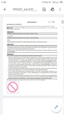
Сборник руководств на английском языке по техническому обслуживанию и ремонту автомобиля Suzuki Grand Vitara серии JB с 2005 года выпуска.
- Автор: —
- Издательство: Suzuki Motor Corporation
- Год издания: —
- Страниц: —
- Формат: PDF
- Размер: 190,8 Mb

Сборник руководств на английском, немецком, французском и испанском языках по техническому обслуживанию и ремонту автомобилей Suzuki Grand Vitara серии SQ и Suzuki Grand Vitara XL-7 серии JA с 1997 года выпуска.
- Автор: —
- Издательство: Suzuki Motor Corporation
- Год издания: —
- Страниц: —
- Формат: PDF
- Размер: 800,5 Mb
Мультимедийное руководство на 11 языках по техническому обслуживанию и ремонту автомобиля Suzuki Grand Vitara второго поколения.
- Автор: —
- Издательство: —
- Год издания: —
- Страниц: —
- Формат: MDF
- Размер: 149,5 Mb
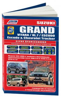
Руководство по эксплуатации, техническому обслуживанию и ремонту + каталог расходных запчастей автомобилей Chevrolet Tracker и Suzuki Escudo/Grand Escudo/Grand Vitara/Grand Vitara XL-7 1997-2006 годов выпуска с бензиновыми двигателями.
- Автор: —
- Издательство: Легион-Автодата
- Год издания: —
- Страниц: 534
- Формат: —
- Размер: —
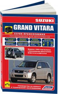
Руководство по эксплуатации, техническому обслуживанию и ремонту + каталог расходных запчастей автомобиля Suzuki Grand Vitara с 2005 года выпуска с бензиновыми двигателями объемом 1,6/2,0 л.
- Автор: —
- Издательство: Легион-Автодата
- Год издания: —
- Страниц: 446
- Формат: —
- Размер: —
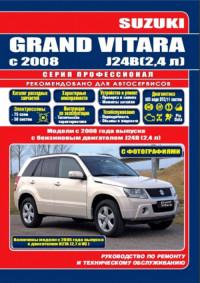
Руководство по эксплуатации, техническому обслуживанию и ремонту + каталог расходных запчастей автомобиля Suzuki Grand Vitara с 2008 года выпуска с бензиновым двигателем объемом 2,4 л.
- Автор: —
- Издательство: Легион-Автодата
- Год издания: 2015
- Страниц: 569
- Формат: —
- Размер: —
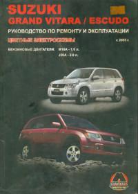
Руководство по эксплуатации и ремонту автомобилей Suzuki Grand Vitara и Suzuki Escudo с 2005 года выпуска с бензиновыми двигателями объемом 1,6/2,0 л.
- Автор: —
- Издательство: Монолит
- Год издания: 2009
- Страниц: 386
- Формат: DjVu
- Размер: 12,3 Mb

Руководство по эксплуатации и ремонту автомобилей Suzuki Grand Vitara и Suzuki Escudo с 2005 года выпуска с бензиновыми двигателями объемом 1,6/2,0/2,4/3,2 л.
- Автор: —
- Издательство: Монолит
- Год издания: —
- Страниц: 446
- Формат: —
- Размер: —

Руководство по эксплуатации и техническому обслуживанию автомобиля Suzuki Grand Vitara с 2005 года выпуска.
- Автор: —
- Издательство: MoToR
- Год издания: —
- Страниц: 240
- Формат: —
- Размер: —
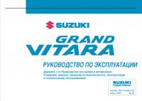
Руководство по эксплуатации и техническому обслуживанию автомобиля Suzuki Grand Vitara с 2005 года выпуска.
- Автор: —
- Издательство: Suzuki Motor Corporation
- Год издания: 2005
- Страниц: 261
- Формат: PDF
- Размер: 2,5 Mb
Мультимедийное руководство по техническому обслуживанию и ремонту автомобиля Suzuki Grand Vitara серии SQ с 2005 года выпуска.
- Автор: —
- Издательство: —
- Год издания: —
- Страниц: —
- Формат: —
- Размер: 174,8 Mb
Руководство по эксплуатации, техническому обслуживанию и ремонту автомобиля Suzuki Grand Vitara с 2008 года выпуска.
- Автор: И.А. Карпов
- Издательство: Арус
- Год издания: —
- Страниц: 227
- Формат: PDF
- Размер: 202,5 Mb
Руководство по эксплуатации, техническому обслуживанию и ремонту автомобилей Suzuki Escudo/Grand Escudo/Grand Vitara, Mazda Levante и Chevrolet Tracker 1997-2005 года выпуска.
- Автор: —
- Издательство: Мир Автокниг
- Год издания: —
- Страниц: 464
- Формат: —
- Размер: —

Руководство по эксплуатации, техническому обслуживанию и ремонту автомобилей Suzuki Escudo/Grand Escudo/Grand Vitara, Mazda Levante и Chevrolet Tracker 1997-2005 года выпуска.
- Автор: —
- Издательство: Мир Автокниг
- Год издания: —
- Страниц: 464
- Формат: —
- Размер: —

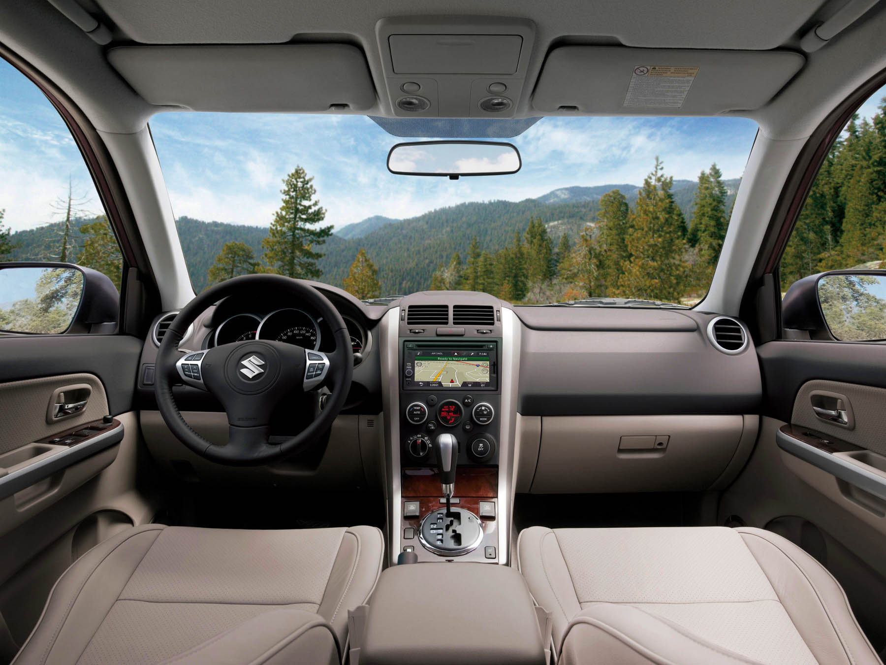
Сузуки Гранд Витара (JT, Escudo) руководство по эксплуатации и техническому обслуживанию с бензиновыми двигателями: M16A 1.6 л (1586 см³) 106 л.с./78 кВт, J20A 2.0 л (1995 см³) 140 л.с./104 кВт, J24B 2.4 л (2393 см³) 166-169 л.с./122-124 кВт, N32A 3.2 л (3195 см³) 233 л.с./171 кВт; Инструкция пользователя автомобиль повышенной проходимости Suzuki Grand Vitara компактный кроссовер с кузовами пяти- и трехдверный универсал повышенной вместимости передне- и полноприводные модели второго (Vitara третьего) поколения выпуска с 2005 года
ЕСЛИ ВЫ ВИДИТЕ ОШИБКУ 406 Not Acceptable и не видите документ, то скорей всего у Вас IP РФ и его надо сменить, на любой другой страны, с помощью VPN ( Scribd и SlideShare блокируют посетителей с Российским IP).
Suzuki Grand Vitara видео замена воздушного фильтра и фильтра салона, передних и задних тормозных колодок (Сузуки Гранд Витара с 05)
Suzuki Grand Vitara Mark II (Vitara III) общая информация (Сузуки Гранд Витара 2005-2015)

ВОЗДУШНЫЙ ФИЛЬТР
Если воздушный фильтр забит пылью, он создает повышенное сопротивление забору воздуха, что приводит к снижению мощности двигателя и увеличению расхода топлива.
Регулярно проверяйте фильтр и очищайте его следующим образом:
1. Снимите крышку корпуса фильтра. Выньте сменный элемент из крышки.
2. В Вашем автомобиле установлен элемент сухого типа.
Помните, что его надо чистить определенным способом:
3. Продуйте элемент изнутри сжатым воздухом. При необходимости замените элемент новым.
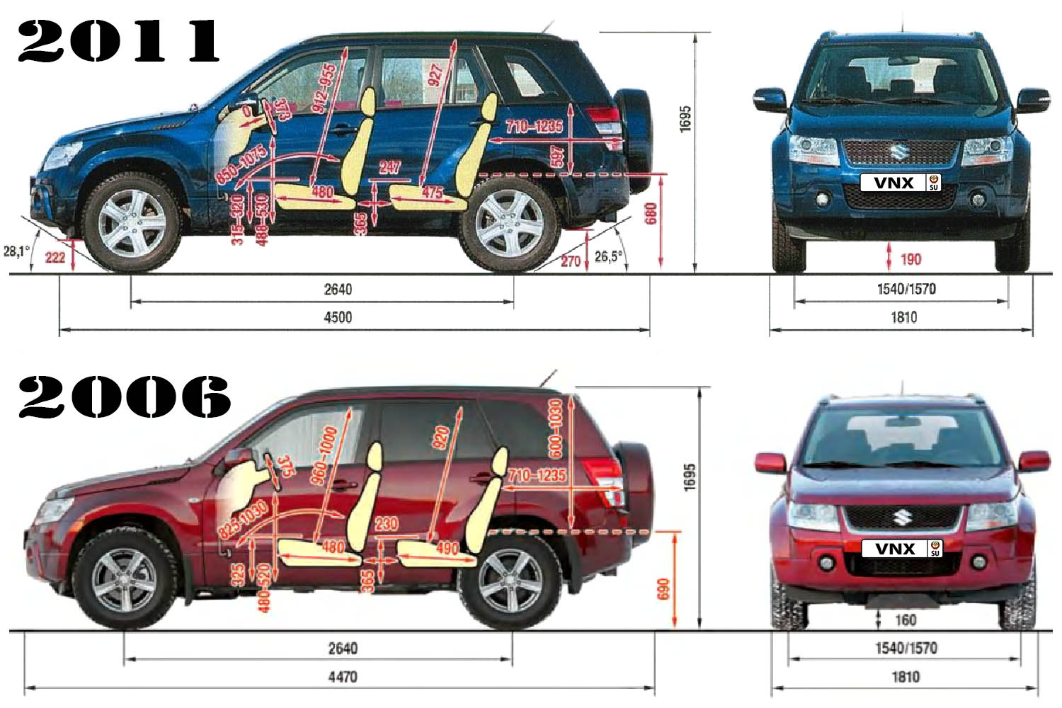
| № | Спецификация / Specs | Данные |
| Габариты (мм/mm) и масса (кг/kg) / Dimensions and Weight | ||
| 1 | Длина / Length | 4500 с запасным колесом |
| 2 | Ширина (без/с зеркалами) / Width | 1810 |
| 3 | Высота (загружен/пустой) / Height | 1695 с багажником на крыше |
| 4 | Колёсная база / Wheelbase | 2640 |
| 5 | Дорожный просвет (клиренс) / Ground clearance | 190⇒160 |
| 6 | Снаряжённая масса / Total (curb) weight | 1584–1670 |
| Полная масса / Gross (max.) weight | 2100 | |
|
Двигатель / Engine |
||
| 7 | Тип / Engine Type, Code | Бензиновый, жидкостного охлаждения, четырехтактный, J24B VVT |
| 8 | Количество цилиндров / Cylinder arrangement: Total number of cylinders, of valves | 4-цилиндровый, 16V, рядный 24V, V-образный, DOHC с верхним расположением двух распределительных валов |
| 9 | Диаметр цилиндра / Bore | 92.0 мм |
| 10 | Ход поршня / Stroke | 90.0 мм |
| 11 | Объём / Engine displacement | 2393 см³ |
| 12 | Система питания / Fuel supply, Aspiration | Многоточечный впрыск топлива MPFI |
| Атмосферный | ||
| 13 | Степень сжатия / Compression ratio | 10.0:1 |
| 14 | Максимальная мощность / Max. output power kW (HP) at rpm | 124 кВт (169 л.с.) при 6000 об/мин |
| 15 | Максимальный крутящий момент / Max. torque N·m at rpm | 227 Нм при 3800 об/мин |
|
Трансмиссия / Transmission |
||
| 16 | Сцепление / Clutch type | Гидротрансформатор с блокировкой / Torque Converter |
| 17 | КПП / Transmission type | АКПП 4 Автоматическая, четырёхступенчатая, гидромеханическая, адаптивная, многорежимная полноприводная трансмиссия с возможностью блокировки межосевого дифференциала и включения понижающей передачи |
О Книге
- Название: Suzuki Grand Vitara руководство по эксплуатации
- Бензиновые двигатели: M16A 1.6 л (1586 см³) 106 л.с./78 кВт, J20A 2.0 л (1995 см³) 140 л.с./104 кВт, J24B 2.4 л (2393 см³) 166-169 л.с./122-124 кВт, N32A 3.2 л (3195 см³) 233 л.с./171 кВт
- Выпуск с 2005 года
- Серия: «Owner Guide»
- Год издания: июль 2008
- Автор: Коллектив авторов
- Издательство: «Suzuki Motor Corporation»
- Формат: PDF
- Страниц в книге: 306
- Размер: 10.41 МБ
- Язык: Русский
- Количество электросхем: 0

-
-
#1
Последнее редактирование модератором: 29 Март 2015
-
-
#2
Ответ: Руководство по ремонту
спасибо большое
-
-
#3
Ответ: Руководство по ремонту
Пожалуйста!
-
-
#4
Ответ: Руководство по ремонту (на русском языке)
А про НСГВ 2008 с движками 2.4 и 3.2 нету случайно книжки?
-
-
#5
Ответ: Руководство по ремонту (на русском языке)
Ну что я могу сказатьОх ёёё, не РЕСПЕКТИЩЕ !!!!!
-
-
#6
Ответ: Руководство по ремонту (на русском языке)
А про НСГВ 2008 с движками 2.4 и 3.2 нету случайно книжки?
не интересовался. сегодня поищу.
-
-
#7
Ответ: Руководство по ремонту (на русском языке)
Спасибо большое
-
-
#8
Ответ: Руководство по ремонту (на русском языке)
Тут где то и цветое для 2.0 было…
Я скачал.
corkscrew
Guest
-
-
#9
Ответ: Руководство по ремонту (на русском языке)
не интересовался. сегодня поищу.
Видимо не нашёл . Очень жаль!!
Может есть у кого книжка на 2,4 L с 2008 года? Отсканируйте, пожалуйста, поделитесь!:whistling: можно в личку или на мыло. Заранее благодарен.
-
-
#10
Ответ: Руководство по ремонту (на русском языке)
точно, не нашел.
но, по крайней мере, убедился, что он вообще существует — электронный вариант такой книги. изредка где-то появляется, но раздачу быстро прикрывают.
-
-
#11
Ответ: Руководство по ремонту (на русском языке)
Ищется руководство по рем., экспл. и тех. обслуживанию автомобилей Suzuki G. V с 2005 г. вып. с двигателем объемом 2,4 л. Поделитесь плз у кого есть…
-
-
#13
Ответ: Руководство по ремонту (на русском языке)
smit, Фигасе, ну и цена у книжки. Хотелось бы конечно полностью, ведь сегодня нужно одно, завтра другое… Но 524 страницы сканировать это пожалуй слишком жестко. Может у кого есть в pdf или jvu? Если нет, то буду покупать книгу. И спасибо за ссылку
-
-
#14
Ответ: Руководство по ремонту (на русском языке)
я сначала тоже скачал для 2.0, но как оказалось 2.4 существенно отличается.
Добавлено через 3 минуты
Knight, кстати в ваших краях подешевле будет всяко: сама книга 1182 + доставка:
По Санкт-Петербургу и Ленинградской области до 105 км от КАД мы осуществляем курьерскую доставку.
Сроки выполнения заказа: 1-3 дня после передачи заказа в службу доставки. Если Вы делаете заказ до 13:00, и если все товары заказа есть в наличии на нашем складе, мы доставим Ваш заказ в этот же день.
Время доставки: ежедневно с 9:00 до 22:00.
Стоимость доставки:
в пределах КАД: 149 рублей;
за КАД до 5 км: 319 рублей;
за КАД до 17 км: 539 рублей;
за КАД до 30 км: 709 рублей;
за КАД до 65 км: 989 рублей;
за КАД до 105 км: 1309 рублей;
Для всех заказов свыше 2000 рублей доставка — бесплатная.
-
-
#15
Ответ: Руководство по ремонту (на русском языке)
Я тут выкладывал скан для 2л и 1.6л, 140мб http://www.suzuki-club.ru/forum/showthread.php?t=63498 — взял да сосканировал 416 стр., очень удобно бывает в электронном виде поглядеть. А купил за 1тр сразу после покупки авто год назад. Без азбуки не жизнь, сервисы обдерут как липку сразу .
-
-
#16
Ответ: Руководство по ремонту (на русском языке)
Да мне не жалко, просто особенно сейчас, в конце года цейтнот образовался. А информации много, действительно много полезной в книжке, причем там четыре модификации описаны — 1.6, 2.0, 2.4, 3.2.
-
-
#17
Ответ: Руководство по ремонту (на русском языке)
Много инфы, но часто слишком сжато изложено и многих секретов то нету, сравнивал я с заводскими мануалами на английском, немецком, французском, лежат кстати здесь на форуме в файловом архиве 200мб на все движки НСГВ
-
-
#19
Cпасибо за ув. )). Не возражаю совсем. А вот файловый архив нашего форума с заводскими мануалами чёт недоступен стал, ссылки не работают.
-
-
#21
надеюсь все, кому нужно было, уже скачали.
можно удалять?
-
-
#22
а че мешает? новичков на ветке каждый день прибывает!
книга реально хорошая!
-
-
#23
Всем привет!
Может и мне кто поможет. В поисках!
Может есть у кого книжка на 2,4 L с 2008 года?
Отсканируйте, пожалуйста, поделитесь! Можно в личку или на мыло (casim@mail.ru). Заранее благодарен.
-
-
#27
Всем привет!
скину еще такое руMazda Levante, Chevrolet Tracker, Suzuki Grand Vitara, Escudo 1997-2004. Устройство, техническое[DOUBLEPOST=1544900342,1544900299][/DOUBLEPOST]не понял как вставить.. пишет большой файл( чуть позже скину ссылку