Материал из BikesWiki — энциклопедия японских мотоциклов
Перейти к: навигация, поиск

Suzuki GSF650 Bandit
Ниже представлены прямые ссылки на скачку сервисной документации.
Для Suzuki GSF 650 Bandit
- Сервисный мануал (Service Manual) для Suzuki GSF650/GSF650S Bandit (2005)
- Сервисный мануал (Service Manual) для Suzuki GSF650/A/S/SA/GSX650F Bandit (2007)
Обзор модели
- Suzuki GSF 650 Bandit
Источник — «https://bikeswiki.ru/index.php?title=Suzuki_GSF650_Bandit:_мануалы&oldid=9829»
Категория:
- Сервисная документация
- Manuals
- Brands
- Suzuki Manuals
- Motorcycle
- GSF650
Manuals and User Guides for Suzuki GSF650. We have 3 Suzuki GSF650 manuals available for free PDF download: Service Manual

GSF650/S
FOREWORD
This manual contains an introductory description on
the SUZUKI GSF650/S and procedures for its
inspection/service and overhaul of its main components.
Other information considered as generally known is
not included.
Read the GENERAL INFORMATION section to
familiarize yourself with the motorcycle and its maintenance. Use this section as well as other sections
to use as a guide for proper inspection and service.
This manual will help you know the motorcycle better so that you can assure your customers of fast
and reliable service.
* This manual has been prepared on the basis of
the latest specifications at the time of publication. If modifications have been made since
then, differences may exist between the content
of this manual and the actual motorcycle.
* Illustrations in this manual are used to show the
basic principles of operation and work procedures. They may not represent the actual
motorcycle exactly in detail.
* This manual is written for persons who have
enough knowledge, skills and tools, including
special tools, for servicing SUZUKI motorcycles. If you do not have the proper knowledge
and tools, ask your authorized SUZUKI motorcycle dealer to help you.
!
Inexperienced mechanics or mechanics
without the proper tools and equipment
may not be able to properly perform the
services described in this manual.
Improper repair may result in injury to the
mechanic and may render the motorcycle
unsafe for the rider and passenger.
© COPYRIGHT SUZUKI MOTOR CORPORATION 2004
GROUP INDEX
GENERAL INFORMATION
1
PERIODIC MAINTENANCE
2
ENGINE
3
FUEL SYSTEM
4
CHASSIS
5
ELECTRICAL SYSTEM
6
SERVICING INFORMATION
7
HOW TO USE THIS MANUAL
TO LOCATE WHAT YOU ARE LOOKING FOR:
1. The text of this manual is divided into sections.
2. The section titles are listed in the GROUP INDEX.
3. Holding the manual as shown at the right will allow you to find
the first page of the section easily.
4. The contents are listed on the first page of each section to
help find the item and page you need.
COMPONENT PARTS AND WORK TO BE DONE
Under the name of each system or unit, is its exploded view. Work instructions and other service information
such as the tightening torque, lubricating points and locking agent points, are provided.
Example: Front wheel
1
2
3
4
5
6
7
8
9
0
A
A
B
Front axle
Dust seal
Brake disc (RH)
Bearing (RH)
Spacer
Bearing (LH)
Brake disc (LH)
Collar
Front wheel
Air bleeder valve
Balancer
Front axle
Brake disc bolt
"
ITEM
A
B
N·m
65
23
kgf-m
6.5
2.3
SYMBOL
Listed in the table below are the symbols indicating instructions and other information necessary for servicing. The meaning of each symbol is also included in the table.
SYMBOL
DEFINITION
SYMBOL
DEFINITION
Torque control required.
Data beside it indicates specified
torque.
Apply THREAD LOCK “1342”.
99000-32050
Apply oil.
Use engine oil unless otherwise specified.
Apply THREAD LOCK SUPER “1360”.
99000-32130
Apply molybdenum oil solution (mixture
of engine oil and SUZUKI MOLY PASTE
in a ratio of 1:1).
Use fork oil.
99000-99044-10G
Apply SUZUKI SUPER GREASE “A”.
99000-25010
Apply or use brake fluid.
Apply SUZUKI MOLY PASTE.
99000-25140
Measure in voltage range.
Apply SUZUKI SILICONE GREASE.
99000-25100
Measure in resistance range.
Apply PBC GREASE.
99000-25110
Measure in current range.
Apply THERMO-GREASE.
99000-59029
Measure in diode test range.
Apply SUZUKI BOND “1207B”.
99000-31140
Measure in continuity test range.
Apply SUZUKI BOND “1215”.
99000-31110
Use special tool.
Apply THREAD LOCK SUPER “1303”.
99000-32030
Indication of service data.
Apply THREAD LOCK SUPER “1322”.
99000-32110
GENERAL INFORMATION
1-1
GENERAL INFORMATION
1
CONTENTS
WARNING/CAUTION/NOTE .........................................................................1GENERAL PRECAUTIONS ...........................................................................1SUZUKI GSF650 (2005-MODEL) ..................................................................1SUZUKI GSF650S (2005-MODEL) ................................................................1SERIAL NUMBER LOCATION ......................................................................1FUEL AND OIL RECOMMENDATION ..........................................................1FUEL (For Canada) ...............................................................................1FUEL (For other countries) ..................................................................1ENGINE OIL ...........................................................................................1BRAKE FLUID ........................................................................................1FRONT FORK OIL .................................................................................1BREAK-lN PROCEDURES ...........................................................................1CYLINDER IDENTIFICATION .......................................................................1INFORMATION LABELS ...............................................................................1SPECIFICATIONS .........................................................................................1-
COUNTRY AND AREA CODES
The following codes stand for the applicable country(-ies) and area(-s).
CODE
E-02
E-19
E-28
COUNTRY OR AREA
England (UK)
European markets
Canada
2
2
4
4
4
5
5
5
5
5
5
6
6
7
8
1-2
GENERAL INFORMATION
WARNING/CAUTION/NOTE
Please read this manual and follow its instructions carefully. To emphasize special information, the symbol
and the words WARNING, CAUTION and NOTE have special meanings. Pay special attention to the messages highlighted by these signal words.
!
Indicates a potential hazard that could result in death or injury.
"
Indicates a potential hazard that could result in motorcycle damage.
NOTE:
Indicates special information to make maintenance easier or instructions clearer.
Please note, however, that the warnings and cautions contained in this manual cannot possibly cover all
potential hazards relating to the servicing, or lack of servicing, of the motorcycle. In addition to the WARNINGS and CAUTIONS stated, you must use good judgement and basic mechanical safety principles. If you
are unsure about how to perform a particular service operation, ask a more experienced mechanic for
advice.
GENERAL PRECAUTIONS
!
* Proper service and repair procedures are important for the safety of the service mechanic and
the safety and reliability of the motorcycle.
* When 2 or more persons work together, pay attention to the safety of each other.
* When it is necessary to run the engine indoors, make sure that exhaust gas is forced outdoors.
* When working with toxic or flammable materials, make sure that the area you work in is wellventilated and that you follow all of the material manufacturer’s instructions.
* Never use gasoline as a cleaning solvent.
* To avoid getting burned, do not touch the engine, engine oil, oil cooler and exhaust system
until they have cooled.
* After servicing the fuel, oil, exhaust or brake systems, check all lines and fittings related to
the system for leaks.
GENERAL INFORMATION
"
* If parts replacement is necessary, replace the parts with Suzuki Genuine Parts or their equivalent.
* When removing parts that are to be reused, keep them arranged in an orderly manner so that
they may be reinstalled in the proper order and orientation.
* Be sure to use special tools when instructed.
* Make sure that all parts used in reassembly are clean. Lubricate them when specified.
* Use the specified lubricant, bond or sealant.
* When removing the battery, disconnect the negative cable first and then the positive cable.
When reconnecting the battery, connect the positive cable first and then the negative cable,
and replace the terminal cover on the positive terminal.
* When performing service to electrical parts, if the service procedures not require use of battery power, disconnect the negative cable the battery.
* When tightening the cylinder head and case bolts and nuts, tighten the larger sizes first.
Always tighten the bolts and nuts diagonally from the inside working out and to the specified
tightening torque.
* Whenever you remove oil seals, gaskets, packing, O-rings, locking washers, self-locking
nuts, cotter pins, circlips and certain other parts as specified, be sure to replace them with
new ones. Also, before installing these new parts, be sure to remove any left over material
from the mating surfaces.
* Never reuse a circlip. When installing a new circlip, take care not to expand the end gap larger
than required to slip the circlip over the shaft. After installing a circlip, always ensure that it is
completely seated in its groove and securely fitted.
* Use a torque wrench to tighten fasteners to the specified torque. Wipe off grease and oil if a
thread is smeared with them.
* After reassembling, check parts for tightness and proper operation.
* To protect the environment, do not unlawfully dispose of used motor oil, engine coolant and
other fluids: batteries and tires.
* To protect Earth’s natural resources, properly dispose of used motorcycle and parts.
1-3
1-4
GENERAL INFORMATION
SUZUKI GSF650 (2005-MODEL)
* Difference between photographs and actual motorcycles may exist depending on the markets.
SUZUKI GSF650S (2005-MODEL)
* Difference between photographs and actual motorcycles may exist depending on the markets.
SERIAL NUMBER LOCATION
The frame serial number or V.I.N. (Vehicle Identification Number) 1 is stamped on the right side of the
steering head pipe and frame down tube. The engine serial number 2 is located on the right side of the
crankcase. These numbers are required especially for registering the machine and ordering spare parts.
GENERAL INFORMATION
1-5
FUEL AND OIL RECOMMENDATION
FUEL (For Canada)
Use only unleaded gasoline of at least 87 pump octane (R/2 + M/2) or 91 octane or higher rated by the
research method.
Gasoline containing MTBE (Methyl Tertiary Butyl Ether), less than 10% ethanol, or less than 5% methanol
with appropriate cosolvents and corrosion inhibitor is permissible.
FUEL (For other countries)
Gasoline used should be graded 91 octane (Research Method) or higher. An unleaded gasoline is recommended.
ENGINE OIL
Oil quality is a major contributor to your engine’s performance
and life. Always select good quality engine oil. Use SF/SG or
SH/SJ with JASO MA in API (American Petroleum Institute)
classification.
Suzuki recommends the use of SAE 10W-40 engine oil. If SAE
10W-40 engine oil is not available, select an alternative according to the following chart.
MULTIGRADE
TEMP.
BRAKE FLUID
Specification and classification: DOT 4
!
Since the brake system of this motorcycle is filled with a glycol-based brake fluid by the manufacturer, do not use or mix different types of fluid such as silicone-based and petroleum-based
fluid for refilling the system, otherwise serious damage will result.
Do not use any brake fluid taken from old or used or unsealed containers.
Never re-use brake fluid left over from a previous servicing, which has been stored for a long
period.
FRONT FORK OIL
Use fork oil #10 or equivalent fork oil.
1-6
GENERAL INFORMATION
BREAK-lN PROCEDURES
During manufacture only the best possible materials are used and all machined parts are finished to a very
high standard but it is still necessary to allow the moving parts to “BREAK-IN” before subjecting the engine
to maximum stresses. The future performance and reliability of the engine depends on the care and restraint
exercised during its early life. The general rules are as follows.
• Keep to these break-in engine speed limits:
Initial 800 km : Below 6 000 r/min
Up to 1 600 km : Below 9 000 r/min
Over 1 600 km : Below 12 000 r/min
• Upon reaching an odometer reading of 1 600 km you can subject the motorcycle to full throttle operation.
However, do not exceed 12 000 r/min at any time.
CYLINDER IDENTIFICATION
The four cylinders of this engine are identified as No. 1, 2, 3 and No. 4 cylinder, as counted from left to right
(as viewed by the rider on the seat).
#1
#2
#3
#4
GENERAL INFORMATION
1-7
INFORMATION LABELS
No.
1
2
3
4
5
6
7
Label name
Information label
Fuel caution label
Screen label
Warning steering label
Tire information label
General warning label
ICES Canada label
8
I.D. plate
9
Safety plate
GSF650 GSF650A GSF650U GSF650UA GSF650S GSF600SA GSF650SU GSF650SUA
E-28
E-28
E-02
E-02
E-02
E-28
E-28
Except
E-28
Except
E-28
E-28
E-28
E-02
1-8
GENERAL INFORMATION
SPECIFICATIONS
DIMENSIONS AND DRY MASS
Overall length....................................................... 2 110 mm
Overall width ........................................................
770 mm
Overall height....................................................... 1 085/1 095 mm .........Low/High ..................GSF650
1 225 mm .....................................................GSF650S
Wheelbase ........................................................... 1 440 mm
Ground clearance ................................................
130 mm
Seat height...........................................................
770/790 mm ...........Low/High
Dry mass..............................................................
201 kg........................................................GSF650
204 kg........................................................GSF650S
ENGINE
Type .....................................................................
Number of cylinders .............................................
Bore .....................................................................
Stroke...................................................................
Four-stroke, air-cooled, DOHC
4
65.5 mm
48.7 mm
Displacement .......................................................
Compression ratio................................................
Carburetor............................................................
Air cleaner............................................................
Starter system......................................................
Lubrication system ...............................................
Idle speed ............................................................
656 cm
10.5 : 1
KEIHIN CVR32
Non-woven fabric element
Electric
Wet sump
1 200 ± 100 r/min
3
DRIVE TRAIN
Clutch...................................................................
Transmission........................................................
Gearshift pattern ..................................................
Primary reduction ratio.........................................
Gear ratios, Low ................................................
2nd.................................................
3rd .................................................
4th..................................................
5th..................................................
Top ................................................
Final reduction ratio .............................................
Drive chain ...........................................................
Wet multi-plate type
6-speed constant mesh
1-down, 5-up
1.744 (75/43)
3.083 (37/12)
2.062 (33/16)
1.647 (28/17)
1.400 (28/20)
1.227 (27/22)
1.095 (23/21)
3.133 (47/15)
RKFS50SMOZ1, 112 links
GENERAL INFORMATION
CHASSIS
Front suspension.................................................
Rear suspension .................................................
Front suspension stroke......................................
Rear wheel travel ................................................
Caster..................................................................
Trail .....................................................................
Steering angle .....................................................
Turning radius .....................................................
Front brake ..........................................................
Rear brake ..........................................................
Front tire size ......................................................
Rear tire size .......................................................
Telescopic, coil spring, oil damped
Link type, coil spring, oil damped
130 mm
126 mm
26°
108 mm
35° (right & left)
2.8 m
Disc brake, twin
Disc brake
120/70ZR17M/C (58W), tubeless
160/60ZR17M/C (69W), tubeless
ELECTRICAL
Ignition type.........................................................
Ignition timing ......................................................
Spark plug ...........................................................
Battery .................................................................
Generator ............................................................
Main fuse.............................................................
Fuse ....................................................................
Headlight .............................................................
Parking or city light ..............................................
Turn signal light...................................................
Brake light/Taillight ..............................................
Speedometer light ...............................................
Tachometer light .................................................
Neutral indicator light ..........................................
High beam indicator light.....................................
Turn signal indicator light ....................................
Oil pressure indicator light...................................
Electronic ignition (Transistorized)
10° B.T.D.C. at 1 200 r/min
NGK CR8EK or DENSO U24ETR
12 V 28.8 kC (8 Ah)/10 HR
Three-phase A.C. generator
30 A
10/15/15/10/10 A
12 V 60/55 W H4 ......................................... GSF650
12 V 55 W H7: Upper and Lower beam....... GSF650S
12 V 5 W ...................................................... GSF650
12 V 5 W × 2................................................ GSF650S
12 V 21 W
12 V 21/5 W
LED
LED
LED
LED
LED
LED
CAPACITIES
Fuel tank, including reserve...............................
reserve..............................................
Engine oil, oil change .........................................
with filter change...............................
overhaul ............................................
20.0 L
4.5 L
3 300 ml
3 500 ml
4 600 ml
These specifications are subject to change without notice.
1-9
PERIODIC MAINTENANCE
2-1
PERIODIC MAINTENANCE
CONTENTS
PERIODIC MAINTENANCE SCHEDULE .......................................................2- 2
PERIODIC MAINTENANCE CHART .....................................................2- 2
LUBRICATION POINTS .........................................................................2- 3
MAINTENANCE AND TUNE-UP PROCEDURES ..........................................2- 4
VALVE CLEARANCE ............................................................................2- 4
SPARK PLUGS ......................................................................................2- 6
EXHAUST PIPE BOLTS AND MUFFLER BOLTS ................................2- 7
AIR CLEANER .......................................................................................2- 8
ENGINE OIL AND OIL FILTER ..............................................................2- 9
FUEL LINE .............................................................................................2-11
ENGINE IDLE SPEED ............................................................................2-11
THROTTLE CABLE PLAY .....................................................................2-11
CARBURETOR SYNCHRONIZATION ..................................................2-12
PAIR (AIR SUPPLY) SYSTEM ...............................................................2-12
FUEL FILTER .........................................................................................2-12
CLUTCH CABLE PLAY .........................................................................2-12
DRIVE CHAIN .........................................................................................2-13
BRAKES .................................................................................................2-15
TIRES .....................................................................................................2-18
STEERING ..............................................................................................2-18
FRONT FORKS ......................................................................................2-19
REAR SUSPENSION .............................................................................2-19
CHASSIS BOLTS AND NUTS ...............................................................2-20
COMPRESSION PRESSURE CHECK ............................................................2-22
COMPRESSION TEST PROCEDURE ...................................................2-22
OIL PRESSURE CHECK .................................................................................2-23
OIL PRESSURE TEST PROCEDURE ...................................................2-23
2
6
2-2
PERIODIC MAINTENANCE
PERIODIC MAINTENANCE SCHEDULE
The chart below lists the recommended intervals for all the required periodic service work necessary to keep
the motorcycle operating at peak performance and economy. Maintenance intervals are expressed in terms
of kilometers and months, and are dependant on whichever comes first.
NOTE:
More frequent servicing may be performed on motorcycles that are used under severe conditions.
PERIODIC MAINTENANCE CHART
Item
Interval km
months
Air cleaner element
Exhaust pipe bolts and muffler bolts
Valve clearance
Spark plugs
Fuel line
Fuel filter
Engine oil
Engine oil filter
Idle speed
Throttle cable play
Throttle valve synchronization
PAIR (air supply) system
Clutch cable play
Drive chain
1 000
2
–
T
I
–
–
–
R
R
I
I
–
–
–
I
Brakes
Brake hoses
I
–
Brake fluid
–
Tires
Steering
Front forks
Rear suspension
Chassis bolts and nuts
–
I
–
–
T
6 000
12 000
18 000
12
24
36
I
I
R
–
–
T
–
I
–
I
R
I
I
I
I
I
R
I
R
R
R
–
–
R
I
I
I
I
I
I
–
I
–
–
I
–
I
I
I
I
I
I
Clean and lubricate every 1 000 km.
I
I
I
I
I
I
Replace every 4 years.
I
I
I
Replace every 2 years.
I
I
I
–
I
–
–
I
–
–
I
–
T
T
T
NOTE:
I = Inspect and clean, adjust, replace or lubricate as necessary
R = Replace
T = Tighten
24 000
48
I
T
I
R
I
R
R
–
I
I
I
I
I
I
I
I
I
I
I
I
I
T
PERIODIC MAINTENANCE
2-3
LUBRICATION POINTS
Proper lubrication is important for smooth operation and long life of each working part of the motorcycle.
Major lubrication points are indicated below.
1
2
3
4
Brake lever holder and throttle cables
Brake pedal pivot and right footrest pivot
Clutch lever holder and clutch cable
Side-stand pivot and spring hook
5 Gearshift pivot and left footrest pivot
6 Center stand pivot and spring hook
7 Drive chain
NOTE:
* Before lubricating each part, clean off any rusty spots and wipe off any grease, oil, dirt or grime.
* Lubricate exposed parts which are subject to rust, with a rust preventative spray whenever the motorcycle
has been operated under wet or rainy conditions.
2-4
PERIODIC MAINTENANCE
MAINTENANCE AND TUNE-UP
PROCEDURES
This section describes the servicing procedures for each item in
the Periodic Maintenance Chart.
VALVE CLEARANCE
Inspect initially at 1 000 km (1 month) and every 12 000
km (24 months).
•
•
•
•
•
•
Remove the fuel tank. (!4-3)
Remove the frame head covers. (GSF650 !5-5)
Remove the cowling. (GSF650S !5-5)
Remove the PAIR valve. (!3-97)
Remove all the spark plugs.
Remove the cylinder head cover and signal generator cover.
(!3-12 and -13)
The valve clearance specification is different for both intake and
exhaust valves.
Valve clearance adjustment must be checked and adjusted 1) at
the time of periodic inspection, 2) when the valve mechanism is
serviced, and 3) when the camshafts are removed for servicing.
" Valve clearance (when cold):
IN.: 0.10 – 0.15 mm
EX.: 0.18 – 0.23 mm
NOTE:
* The camshafts must be at positions A or B, in order to check
or adjust the valve clearance. Clearance readings should not
be taken with the camshafts in any other position than the
ones shown.
* The valve clearance should only be checked when the engine
is cold.
* Turn the crankshaft clockwise using a 19-mm wrench. Make
sure that all of the spark plugs have been removed.
• Turn the crankshaft clockwise and align the “T” mark on the
signal generator rotor with the center of the pickup coil. Also,
position the notches 1 on the right end of each camshaft as
shown. Then, measure the following valve clearance C:
Cylinder #1: Intake and exhaust valve clearance
Cylinder #2: Exhaust valve clearance
Cylinder #3: Intake valve clearance
IN.
EX.
PERIODIC MAINTENANCE
• Insert the thickness gauge between the valve stem end and
adjusting screw on the rocker arm. If the clearance is out of
specification, hold the locknut with a wrench and use the special tool to adjust the clearance.
# 09900-20803: Thickness gauge
09917-14910: Valve adjuster driver
$
Both the right and left valve clearances should be as
closely as possible.
• Turn the crankshaft clockwise 360° (one full rotation) and
align the “T” mark on the signal generator rotor with the center
of the pickup coil. Also, position the notches 2 on the right
end of each camshaft as shown.
• Measure the valve clearances of the remaining valves D and
adjust them if necessary.
Camshaft position
Notch 1 position
Intake camshaft
Exhaust camshaft
C
D
• When installing the cylinder head cover, apply the recommended bond to the cylinder head cover groove and camshaft
end caps. (!3-83)
% 99000-31140: SUZUKI BOND “1207B”
• Tighten the cylinder head cover bolts to the specified torque.
(!3-84, 7-33)
• Install the signal generator cover.
2-5
2-6
PERIODIC MAINTENANCE
SPARK PLUGS
Inspect every 6 000 km (6 months) and replace every
12 000 km (24 months).
• Remove all of the spark plugs.
NOTE:
If it is difficult to remove any of the spark plug caps, pry them up
using a screwdriver.
# 09930-10121: Spark plug wrench set
09900-20803: Thickness gauge
Standard
Cold type
NGK
CR8EK
CR9EK
DENSO
U24ETR
U27ETR
CARBON DEPOSITS
Check to see if there are carbon deposits on the spark plug.
If carbon is deposited, remove it using a spark plug cleaner
machine or carefully use a tool with a pointed end.
SPARK PLUG GAP
Measure the spark plug gap using a thickness gauge.
If out of specification, regap the spark plug.
" Spark plug gap: 0.6 – 0.7 mm
# 09900-20803: Thickness gauge
0.6 – 0.7 mm
PERIODIC MAINTENANCE
ELECTRODE’S CONDITION
Check the condition of the electrode.
If it is extremely worn or burnt, replace the spark plug.
Replace the spark plug if it has a broken insulator, damaged
threads, etc.
$
Check the thread size and reach when replacing the
spark plug. If the reach is too short, carbon will be
deposited on the screw portion of the spark plug hole
and engine damage may result.
SPARK PLUG INSTALLATION
$
To avoid damaging the cylinder head threads, first finger tighten the spark plug and then tighten it to the
proper torque using the spark plug wrench.
• Insert the spark plugs to the cylinder head by finger tight, and
then tighten them to the specified torque.
& Spark plug: 11 N·m (1.1 kgf-m)
EXHAUST PIPE BOLTS AND
MUFFLER BOLTS
Tighten initially at 1 000 km (1 month) and every
12 000 km (24 months) thereafter.
• Tighten the exhaust pipe bolts and muffler bolts to the specified torque.
& Exhaust pipe bolt: 23 N·m (2.3 kgf-m)
& Muffler mounting bolt 1: 23 N·m (2.3 kgf-m)
Muffler connecting bolt 2: 23 N·m (2.3 kgf-m)
2-7
2-8
PERIODIC MAINTENANCE
AIR CLEANER
Inspect every 6 000 km (12 months) and replace every
18 000 km (36 months).
• Remove the fuel tank. (!4-3)
• Remove the screws.
• Remove the air cleaner element 1.
• Carefully use compressed air to clean the air cleaner element.
$
Always apply compressed air to the inside of the air
cleaner element. If compressed air is applied to the
outside, dirt will be forced into the pores of the air
cleaner element, restricting air flow through the air
cleaner element.
• Reinstall the cleaned or new air cleaner element in the
reverse order of removal.
• When installing the air cleaner element into the air cleaner
box, make sure that the mark points up.
$
If driving under dusty conditions, clean the air cleaner
element more frequently. The surest way to accelerate
engine wear is to operate the engine without the element or to use a torn element. Make sure that the air
cleaner is in good condition at all times. Life of the
engine depends largely on this component.
Mar
Mark
PERIODIC MAINTENANCE
• Remove the drain plug from the air cleaner drain hose to
allow any water to drain out.
ENGINE OIL AND OIL FILTER
(ENGINE OIL)
Replace initially at 1 000 km (2 month) and every 6 000
km (12 months) thereafter.
(OIL FILTER)
Replace initially at 1 000 km (2 month) and every 12 000
km (24 months) thereafter.
The oil should be changed while the engine is warm. Oil filter
replacement at the above intervals, should be done together
with the engine oil change.
ENGINE OIL REPLACEMENT
• Keep the motorcycle upright.
• Place an oil pan below the engine, and drain engine oil by
removing the oil drain plug 1 and filler cap 2.
• Tighten the oil drain plug 1 to the specified torque, and pour
new oil through the oil filler. When performing an oil change
(without oil filter replacement), the engine will hold about 3.3 L
of oil. Use SF/SG or SH/SJ with JASO MA in API (American
Petroleum Institute) classification.
& Oil drain plug: 23 N·m (2.3 kgf-m)
2-9
2-10
PERIODIC MAINTENANCE
• Start up the engine and allow it to run for several minutes at
idling speed.
• Turn off the engine and wait about three minutes, then check
the oil level through the inspection window 3. If the level is
below the “L” mark, add oil to the “F” mark. If the level is
above the “F” mark, drain the oil until the level reaches the “F”
mark.
OIL FILTER REPLACEMENT
• Drain engine oil as described in the engine oil replacement
procedure.
• Remove the oil filter 1 using the special tool.
• Apply engine oil lightly to the O-ring of new oil filter, before
installation.
# 09915-40610: Oil filter wrench
• Install the new oil filter. Turn it by hand until you feel that the
oil filter O-ring has contacted the oil filter mounting surface.
Then, tighten the oil filter two full turns using the special tool.
NOTE:
* Before installing the oil filter, apply a light coat of engine oil
onto its O-ring.
* To properly tighten the oil filter, use the special tool. Never
tighten the oil filter by hand only.
• Add new engine oil and check the oil level as described in the
engine oil replacement procedure.
" NECESSARY AMOUNT OF ENGINE OIL
Oil change: 3.3 L
Oil and filter change: 3.5 L
Engine overhaul: 4.6 L
$
ONLY USE A GENUINE SUZUKI MOTORCYCLE OIL
FILTER.
Other manufacturer’s oil filters may differ in thread
specifications (thread diameter and pitch), filtering
performance and durability which may lead to engine
damage or oil leaks. Also, do not use a genuine Suzuki
automobile oil filter on this motorcycle.
PERIODIC MAINTENANCE
FUEL LINE
Inspect every 6 000 km (12 months).
• Remove the seat.
• Remove the fuel tank mounting bolts. (!4-3)
• Lift up the fuel tank.
Inspect the fuel hoses 1 for damage and fuel leakage. If any
defects are found, the fuel hoses must be replaced.
ENGINE IDLE SPEED
Inspect initially at 1 000 km (2 month) and every 6 000
km (12 months) thereafter.
NOTE:
Make this adjustment when the engine is hot.
• Start the engine, turn the throttle stop screw 1 and set the
engine idle speed between 1 100 and 1 300 r/min.
" Engine idle speed: 1 200 ± 100 r/min
THROTTLE CABLE PLAY
Inspect initially at 1 000 km (2 month) and every 6 000
km (12 months) thereafter.
Adjust the throttle cable play A as follows.
• Loosen the locknut 1 of the throttle pulling cable 2.
• Turn the adjuster 3 in or out until the throttle cable play (at
the throttle grip) A is between 2 – 4 mm.
• Tighten the locknut 1 while holding the adjuster 3.
" Throttle cable play A: 2 – 4 mm
'
After the adjustment is completed, check that handlebar movement does not raise the engine idle speed
and that the throttle grip returns smoothly and automatically.
NOTE:
Major adjustment can be made at the carburetor side adjusters.
(!4-24)
2-11
2-12
PERIODIC MAINTENANCE
CARBURETOR SYNCHRONIZATION
Inspect initially at 1 000 km (2 month) and every 12 000
km (24 months).
(!4-25)
PAIR (AIR SUPPLY) SYSTEM
Inspect every 12 000 km (24 months).
(!3-97)
FUEL FILTER
Inspect every 6 000 km (12 months) and replace every
12 000 km (24 months).
• Lift up the fuel tank. (!2-10)
Check the fuel filter 1 for evidence of dirt and contamination. If
present, replace the fuel filter with a new one. (!4-6)
CLUTCH CABLE PLAY
Inspect every 6 000 km (12 months).
• Loosen the locknut 1 and turn the adjuster 2 all the way into
the clutch lever assembly.
• Remove the clutch release cover.
• Loosen the locknut 3, and turn out the adjusting screw 4 two
or three rotations.
• Then, slowly turn in the adjusting screw 4 until resistance is
felt.
• Then, turn out the adjusting screw 4 1/4 of a turn, and tighten
the locknut 3.
• Loosen the locknut 5, and turn the cable adjuster 6 to obtain
10 – 15 mm of free play A at the clutch lever end.
• Tighten the locknut 5.
" Clutch cable play A: 10 – 15 mm
PERIODIC MAINTENANCE
DRIVE CHAIN
Inspect initially at 1 000 km (2 month) and every 6 000
km (12 months) thereafter.
Lubricate every 1 000 km.
With the transmission in neutral, support the motorcycle using
the center-stand and turn the rear wheel slowly by hand. Visually check the drive chain for the possible defects listed below.
* Loose pins
* Excessive wear
* Damaged rollers
* Improper chain adjustment
* Dry or rusted links
* Missing O-ring seals
* Kinked or binding links
A O-ring
B Grease
If any defects are found, the drive chain must be replaced.
NOTE:
When replacing the drive chain, replace the drive chain and
sprockets as a set.
CHECKING
• Remove the cotter pin. (E-28)
• Loosen the axle nut 1.
• Tense the drive chain fully by turning both chain adjuster bolts
2.
• Count out 21 pins (20 pitches) on the chain and measure the
distance between the two points. If the distance exceeds the
service limit, the chain must be replaced.
" Drive chain 20-pitch length
Service Limit: 319 mm
1 2 3
19 20 21
2-13
2-14
PERIODIC MAINTENANCE
ADJUSTING
• Loosen or tighten both chain adjuster bolts 1 until there is 20
– 30 mm of slack at the middle of the chain between the
engine and rear sprockets as shown. The reference marks 2
on both sides of the swingarm and the edge of each chain
adjuster must be aligned to ensure that the front and rear
wheels are correctly aligned.
• Place the motorcycle on its side-stand for accurate adjustment.
• After adjusting the drive chain, tighten the axle nut 3 to the
specified torque.
• Tighten both chain adjuster bolts 1 securely.
& Rear axle nut: 100 N·m (10.0 kgf-m)
• Replace the cotter pin with a new one. (E-28)
20 – 30 mm
CLEANING AND LUBRICATING
• Clean the drive chain with kerosine. If the drive chain tends to
rust quickly, the intervals must be shortened.
$
Do not use trichloroethylene, gasoline or any similar
solvent.
These fluids have too great a dissolving power for this
chain and they can damage the O-rings. Use only kerosine to clean the drive chain.
• After cleaning and drying the chain, oil it with a heavyweight
motor oil.
$
* Do not use any oil sold commercially as “drive chain
oil”. Such oil can damage the O-rings.
* The standard drive chain is a RKFS50SMOZ1.
SUZUKI recommends to use this standard drive
chain as a replacement.
DRIVE CHAIN CUTTING AND RECONNECTING (!5-70)
PERIODIC MAINTENANCE
BRAKES
(BRAKE)
Inspect initially at 1 000 km (2 month) and every 6 000
km (12 months) thereafter.
(BRAKE HOSE AND BRAKE FLUID)
Inspect every 6 000 km (12 months).
Replace hoses every 4 years. Replace fluid every 2
years.
BRAKE FLUID LEVEL
• Keep the motorcycle upright and place the handlebar straight.
• Check the brake fluid level by observing the lower limit line on
the front and rear brake fluid reservoirs.
• When the brake fluid level is below the lower limit line, replenish with brake fluid that meets the following specification.
( Specification and classification: DOT 4
'
* The brake system of this motorcycle is filled with a
glycol-based brake fluid. Do not use or mix different
types of fluid such as silicone-based and petroleum-based fluids. Do not use any brake fluid taken
from old, used or unsealed containers. Never re-use
brake fluid left over from the last servicing or stored
for a long period of time.
* Brake fluid, if it leaks, will interfere with safe running
and immediately discolor painted surfaces. Check
the brake hoses and hose joints for cracks and oil
leakage before riding.
2-15
2-16
PERIODIC MAINTENANCE
BRAKE PADS
The extent of brake pad wear can be checked by observing the
grooved limit line 1 on the pad. When the wear exceeds the
grooved limit line, replace the pads with new ones. (!5-47)
$
Replace the brake pads as a set, otherwise braking
performance will be adversely affected.
BRAKE PEDAL HEIGHT
• Loosen the locknut 1.
• Turn the push rod 2 until the brake pedal is 60 mm A below
the top of the footrest.
• Tighten the locknut 1 securely.
" Brake pedal height A
Standard: 60 mm
& Master cylinder push rod locknut: 18 N·m (1.8 kgf-m)
BRAKE LIGHT SWITCH
Adjust the rear brake light switch so that the brake light will
come on just before pressure is felt when the brake pedal is
depressed.
PERIODIC MAINTENANCE
AIR BLEEDING THE BRAKE FLUID CIRCUIT
Air trapped in the brake fluid circuit acts like a cushion to absorb
a large proportion of the pressure developed by the master cylinder and thus interferes with the full braking performance of the
brake caliper. The presence of air is indicated by “sponginess”
of the brake lever and also by lack of braking force. Considering
the danger to which such trapped air exposes the machine and
rider, it is essential that, after remounting the brake and restoring the brake system to the normal condition, the brake fluid circuit be purged of air in the following manner:
Front brake
• Fill the master cylinder reservoir to the top of the inspection
window. Place the reservoir cap to prevent dirt from entering.
• Attach a hose to the air bleeder valve, and insert the free end
of the hose into a receptacle.
• Squeeze and release the brake lever several times in rapid
succession and squeeze the lever fully without releasing it.
Loosen the air bleeder valve by turning it a quarter of a turn so
that the brake fluid runs into the receptacle, this will remove
the tension of the brake lever causing it to touch the handlebar grip. Then, close the air bleeder valve, pump and squeeze
the lever, and open the valve. Repeat this process until the
fluid flowing into the receptacle no longer contains air bubbles.
NOTE:
While bleeding the brake system, replenish the brake fluid in the
reservoir as necessary. Make sure that there is always some
fluid visible in the reservoir.
• Close the air bleeder valve, and disconnect the hose. Fill the
reservoir with brake fluid to the top of the inspection window.
& Air bleeder valve: 8 N·m (0.8 kgf-m)
$
Handle brake fluid with care: the fluid reacts chemically with paint, plastics, rubber materials, etc.
Rear brake
NOTE:
Rear brake caliper has two bleeder valves.
2-17
2-18
PERIODIC MAINTENANCE
TIRES
Inspect every 6 000 km (12 months).
TIRE TREAD CONDITION
Operating the motorcycle with excessively worn tires will
decrease riding stability and consequently invite a dangerous
situation. It is highly recommended to replace a tire when the
remaining depth of the tire tread reaches the following specification.
# 09900-20805: Tire depth gauge
" Tire tread depth
Service limit: FRONT 1.6 mm
REAR 2.0 mm
TIRE PRESSURE
If the tire pressure is too high or too low, steering will be
adversely affected and tire wear will increase. Therefore, maintain the correct tire pressure for good roadability and a longer
tire life. Cold inflation tire pressure is as follows.
COLD INFLATION
TIRE PRESSURE
FRONT
REAR
SOLD RIDING
kPa
kgf/cm²
250
2.50
250
2.50
DUAL RIDING
kPa
kgf/cm²
250
2.50
250
2.50
$
The standard tire fitted on this motorcycle is a 120/
70ZR17 M/C (58W) for the front (GSF650: BRIDGESTONE BT011F L, GSF650S: BRIDGESTONE BT011F
J) and a 160/60ZR17 M/C (69W) for the rear (GSF650,
GSF650S: BRIDGESTONE BT020R L). The use of tires
other than those specified may cause instability. It is
highly recommended to use the specified tires.
STEERING
Inspect initially at 1 000 km (2 month) and every 12 000
km (24 months) thereafter.
The steering should be adjusted properly for smooth turning of
the handlebars and safe operation. Overtighten steering prevents smooth turning of the handlebars and too loose steering
will cause poor stability. Check that there is no play in the front
fork. Support the motorcycle so that the front wheel is off the
ground. With the wheel facing straight ahead, grasp the lower
fork tubes near the axle and pull forward. If play is found, readjust the steering. (!5-28)
PERIODIC MAINTENANCE
FRONT FORKS
Inspect every 12 000 km (24 months).
Inspect the front fork for oil leakage, scoring or scratches on the
outer surface of the inner tubes. Replace any defective parts, if
necessary. (!5-15)
REAR SUSPENSION
Inspect every 12 000 km (24 months).
Inspect the rear shock absorbers for oil leakage and check that
there is no play in the swingarm. (!5-38)
2-19
2-20
PERIODIC MAINTENANCE
CHASSIS BOLTS AND NUTS
Tighten initially at 1 000 km (2 month) and every 6 000
km (24 months) thereafter.
Check that all chassis bolts and nuts are tightened to their specified torque. (Refer to page 2-21 for the locations of the following nuts and bolts.)
1
2
3
4
5
6
7
8
9
0
A
B
C
D
E
F
G
H
I
J
K
L
M
N
ITEM
Steering stem head nut
Front fork upper clamp bolt
Front fork lower clamp bolt
Front fork cap bolt
Front axle
Front axle pinch bolt
Handlebar holder bolt
Front brake master cylinder mounting bolt
Front brake caliper mounting bolt
Brake hose union bolt (front & rear)
Air bleeder valve (front & rear)
Brake disc bolt (front & rear)
Rear brake caliper mounting bolt
Rear brake caliper housing bolt
Rear brake master cylinder mounting bolt
Rear brake master cylinder push rod locknut
Front footrest bolt
Front footrest bracket bolt
Swingarm pivot nut
Rear shock absorber mounting nut (upper & lower)
Cushion lever mounting nut
Cushion lever rod mounting nut
Rear axle nut
Rear sprocket nut
N·m
65
23
23
23
65
23
23
10
39
23
8
23
26
37
25
18
35
23
100
50
78
78
100
50
kgf-m
6.5
2.3
2.3
2.3
6.5
2.3
2.3
1.0
3.9
2.3
0.8
2.3
2.6
3.7
2.5
1.8
3.5
2.3
10.0
5.0
7.8
7.8
10.0
5.0
PERIODIC MAINTENANCE
2-21
2-22
PERIODIC MAINTENANCE
COMPRESSION PRESSURE CHECK
The compression pressure reading of a cylinder is a good indicator of its internal condition.
The decision to overhaul the cylinder is often based on the results of a compression test. Periodic maintenance records kept at your dealership should include compression readings for each maintenance service.
COMPRESSION PRESSURE SPECIFICATION
Standard
1 000 – 1 500 kPa
(10 – 15 kgf/cm2)
Limit
800 kPa
(8 kgf/cm2)
Difference
200 kPa
(2 kgf/cm2)
Low compression pressure can indicate any of the following conditions:
* Excessively worn cylinder walls
* Worn piston or piston rings
* Piston rings stuck in grooves
* Poor valve seating
* Ruptured or otherwise defective cylinder head gasket
Overhaul the engine in the following cases:
* Compression pressure in one of the cylinders is less than
800 kPa (8 kgf/cm2).
* The difference in compression pressure between any two cylinders is more than 200 kPa (2 kgf/cm2).
* All compression pressure readings are below 1 000 kPa (10
kgf/cm2) even when they measure more than 800 kPa (8 kgf/
cm2).
COMPRESSION TEST PROCEDURE
NOTE:
* Before testing the engine for compression pressure, make
sure that the cylinder head nuts are tightened to the specified
torque values and the valves are properly adjusted.
* Have the engine warmed-up before testing.
* Make sure that the battery is fully-charged.
Remove the related parts and test the compression pressure in
the following manner.
• Remove the fuel tank. (!4-3)
• Remove all of the spark plugs.
• Install the compression gauge and adaptor in the spark plug
hole. Make sure that the connection is tight.
• Keep the throttle grip in the fully opened position.
• Press the starter button and crank the engine for a few seconds. Record the maximum gauge reading as the cylinder
compression.
• Repeat this procedure with the other cylinders.
# 09915-64510: Compression gauge set
09915-63310: Adaptor
PERIODIC MAINTENANCE
2-23
OIL PRESSURE CHECK
Check the engine oil pressure periodically. This will give a good indication of the condition of the moving
parts.
OIL PRESSURE SPECISFICATION
Above 300 kPa (3 kgf/cm²)
at 3 000 r/min, oil temp. at 60 °C
Below 600 kPa (6 kgf/cm²)
If the oil pressure is lower or higher than specification, the following causes may be considered.
LOW OIL PRESSURE
* Clogged oil filter
* Oil leakage from the oil passage
* Damaged O-ring
* Defective oil pump
* Combination of the above items
HIGH OIL PRESSURE
* Engine oil viscosity is too high
* Clogged oil passage
* Combination of the above items
OIL PRESSURE TEST PROCEDURE
Start the engine and check if the oil pressure indicator light is
turned on. If the light stays on, check the oil pressure indicator
light circuit. If the circuit is OK, check the oil pressure in the following manner.
• Remove the main oil gallery plug 1.
• Install the oil pressure gauge and adaptor into the main oil
gallery.
• Warm up the engine as follows:
Summer: 10 min at 2 000 r/min
Winter: 20 min at 2 000 r/min
• After warm up, increase the engine speed to 3 000 r/min
(observe the tachometer), and read the oil pressure gauge.
# 09915-74521: Oil pressure gauge hose
09915-74540: Oil pressure gauge attachment
09915-77331: Meter (for high pressure)
& Main oil gallery plug: 40 N·m (4.0 kgf-m)
ENGINE
3-1
ENGINE
CONTENTS
ENGINE COMPONENTS REMOVABLE WITH ENGINE IN PLACE ..............3- 2
ENGINE REMOVAL AND INSTALLATION ....................................................3- 3
REMOVAL ..............................................................................................3- 3
INSTALLATION ......................................................................................3- 7
ENGINE DISASSEMBLY ................................................................................3-12
ENGINE COMPONENTS INSPECTION AND SERVICE ................................3-26
CAMSHAFT/CYLINDER HEAD INSPECTION AND SERVICE .............3-26
CYLINDER BLOCK/PISTON INSPECTION ..........................................3-39
CLUTCH/CLUTCH RELEASE ASSEMBLY INSPECTION ...................3-43
STARTER CLUTCH INSPECTION ........................................................3-45
GEARSHIFT LINKAGE INSPECTION ...................................................3-45
TRANSMISSION INSPECTION AND SERVICE ....................................3-47
CONROD/CRANKSHAFT INSPECTION ...............................................3-55
CONROD-CRANK PIN BEARING INSPECTION AND SERVICE .........3-55
CRANKCASE-CRANKSHAFT BEARING INSPECTION
AND SERVICE ......................................................................................3-58
CRANKSHAFT THRUST CLEARANCE ADJUSTMENT ......................3-60
ENGINE REASSEMBLY .................................................................................3-63
ENGINE LUBRICATION SYSTEM ..................................................................3-86
OIL PUMP ...............................................................................................3-86
OIL SUMP FILTER/OIL PRESSURE REGULATOR .............................3-86
OIL PRESSURE SWITCH ......................................................................3-89
OIL COOLER ..........................................................................................3-90
OIL FILTER ............................................................................................3-90
OIL PRESSURE .....................................................................................3-90
OIL JET ..................................................................................................3-91
ENGINE LUBRICATION SYSTEM CHART ...........................................3-93
ENGINE LUBRICATION SYSTEM .........................................................3-94
CYLINDER HEAD COOLING SYSTEM CHART ...................................3-95
CYLINDER HEAD COOLING SYSTEM .................................................3-96
PAIR (AIR SUPPLY) SYSTEM ........................................................................3-97
REMOVAL ..............................................................................................3-97
INSPECTION ..........................................................................................3-97
INSTALLATION ......................................................................................3-98
3
6
3-2
ENGINE
ENGINE COMPONENTS REMOVABLE WITH ENGINE IN PLACE
The parts listed below can be removed and reinstalled without removing the engine from the frame. Refer to
page listed in each section for removal and reinstallation instructions.
ENGINE CENTER
ITEM
Exhaust pipe/muffler
Oil hoses
Oil filter
Oil cooler
Oil pan
Engine oil pressure regulator
Oil sump filter
Carburetors
Cam chain tensioner adjuster
Cylinder head cover
Camshafts
Cylinder head
Cylinder
Pistons
Starter motor
Generator
PAIR system
REMOVAL
!3-5
!3-12
!3-12
!3-6
!3-21
!3-87
!3-87
!4-15
!3-13
!3-12
!3-13
!3-14
!3-14
!3-15
!3-16
!3-16
!3-12, 97
INSPECTION
---------------------------!3-90
!3-87
!3-87
!3-87
!4-20
!3-28
!3-30
!3-26
!3-29
!3-39
!3-40
!6-24
!6-15
!3-97
INSTALLATION
!3-8
!3-84
!3-84
!3-8
!3-69
!3-88
!3-88
!3-10
!3-82
!3-83
!3-79
!3-78
!3-77
!3-76
!3-75
!3-75
!3-85, 98
REMOVAL
!3-4
!3-4
!3-4
!3-20
!3-17
!3-19
!3-20
INSPECTION
------------------!2-13
!6-27
------------------!3-45
INSTALLATION
!3-10
!3-9
!3-9
!3-69
!3-74
!3-70
!3-70
REMOVAL
!3-16
!3-16
!3-16, 89
!3-17
!3-18
!3-19
!3-18
!3-18
!3-19
!3-19
INSPECTION
---------!6-33
!6-40
!3-43
------------------------------------!3-45
----------
INSTALLATION
!3-73
!3-74
!3-74
!3-72
!3-72
!3-71
!3-71
!3-72
!3-71
!3-70
ENGINE LEFT SIDE
ITEM
Gearshift lever
Engine sprocket cover
Engine sprocket/drive chain
Gear position switch
Starter clutch cover
Starter idle gear
Starter clutch
ENGINE RIGHT SIDE
ITEM
Clutch cover
Signal generator
Oil pressure switch
Clutch plates
Clutch sleeve hub
Oil pump driven gear
Generator/oil pump drive gears
Primary driven gear
Gearshift shaft
Gearshift pawl/cam driven gear
ENGINE
ENGINE REMOVAL AND INSTALLATION
REMOVAL
Before taking the engine out of the frame, wash the engine
using a steam cleaner. Engine removal is sequentially explained
in the following steps.
• Drain engine oil. (!2-9)
• Remove the seat and frame covers. (!5-4)
• Remove the frame head covers. (GSF650: !5-5)
• Remove the cowling. (GSF650S: !5-5)
• Remove the fuel tank. (!4-3)
• Remove the air cleaner box mounting bolts 1.
• Remove the luggage box 2. (!5-4)
• Disconnect the battery - lead wire.
• Disconnect the engine ground wire coupler 3.
• Disconnect all of the spark plug caps.
• Disconnect the PAIR valve hoses A to C.
A Air cleaner hose
B Vacuum hose
C PAIR hoses
• Disconnect the breather hose 4.
3-3
3-4
ENGINE
• Remove the carburetor assembly. (!4-15)
• Disconnect the lead wire couplers D to G.
D Signal generator
E Side-stand switch
F Speed sensor
G Gear position switch
• Open the clamps.
• Disconnect the starter motor lead wire 5.
• Disconnect the generator lead wire 6 and coupler 7.
• Disengage the gearshift lever link by removing the bolt.
• Remove the engine sprocket cover along with the clutch cable
and speed sensor.
• Remove the speed sensor rotor 8 and engine sprocket nut 9
while depressing the rear brake pedal.
ENGINE
• Loosen the rear axle nut 0 and chain adjusters A to provide
additional chain slack.
• Remove the engine sprocket B.
• Remove the exhaust pipe bolts.
• Loosen the muffler connecting bolt C.
• Remove the muffler mounting bolts D.
• Remove the muffler assembly.
NOTE:
Support the muffler assembly to prevent it from falling.
• Remove the exhaust pipe gaskets E.
3-5
3-6
ENGINE
• Remove the oil cooler.
• Support the engine with a proper jack.
• Remove the frame down tube F.
• Remove the engine mounting bolts, nuts and spacer G.
• Gradually lower the engine.
ENGINE
3-7
INSTALLATION
Install the engine in the reverse order of engine removal.
• Insert the two long bolts from left side. Install the brackets, spacer, bolts and nuts properly, as shown in
the following illustration.
NOTE:
The engine mounting nuts are self-locking. Once the nuts have been removed, they are no longer of any
use. Be sure to use new nuts and tighten them to the specified torque.
LH
RH
75 N·m
(7.5 kgf-m)
55 N·m
(5.5 kgf-m)
75 N·m
(7.5 kgf-m)
NOTE:
When reusing the removed engine mounting bolts (1 and 2), apply a small quantity of the THREAD LOCK
to their threads.
" 99000-32110: THREAD LOCK SUPER “1322”
# Frame down tube mounting bolt: 50 N·m (5.0 kgf-m)
LENGTH
Bolt 1
Bolt 2
Bolt 3
Spacer RH A
180 mm
130 mm
55 mm
27 mm
#
ITEM
1, 2
3
N·m
75
55
kgf-m
7.5
5.5
3-8
ENGINE
• Tighten the oil cooler mounting bolts 1 to the specified
torque.
# Oil cooler mounting bolt: 10 N·m (1.0 kgf-m)
• Tighten the oil cooler hose union bolts 2 to the specified
torque.
# Oil cooler hose union bolt: 28 N·m (2.8 kgf-m)
$
Use new gasket washers to prevent oil leakage.
NOTE:
When installing new exhaust pipe/muffler assembly connectors,
remove all of the old sealer from the exhaust pipes and from
inside the muffler. Apply the exhaust gas sealer to both the
inside and outside of the new exhaust pipe/muffler assembly
connectors.
EXHAUST GAS SEALER: PREMATEX 1372
• Install the exhaust pipe gaskets 3.
$
Be sure to face the tabs A on the exhaust pipe gaskets 3 to the engine side when installing them.
• Tighten the exhaust pipe bolts and muffler mounting bolts to
the specified torque.
# Exhaust pipe bolt: 23 N·m (2.3 kgf-m)
Muffler mounting bolt: 23 N·m (2.3 kgf-m)
ENGINE
3-9
• Apply THREAD LOCK SUPER to the driveshaft.
% 99000-32030: THREAD LOCK SUPER “1303”
• Tighten the engine sprocket nut 1 to the specified torque.
# Engine sprocket nut 1: 115 N·m (11.5 kgf-m)
• Apply a small quantity of THREAD LOCK “1342” to the speed
sensor rotor bolt.
& 99000-32050: THREAD LOCK “1342”
• Tighten the speed sensor rotor bolt 2 to the specified torque.
# Speed sensor rotor bolt 2: 20 N·m (2.0 kgf-m)
• Before installing the engine sprocket cover, apply a small
quantity of SUZUKI SUPER GREASE “A” to the clutch
release mechanism.
' 99000-25010: SUZUKI SUPER GREASE “A”
• Install the spark plug caps onto the spark plugs. Make sure
that each spark plug cap is installed in the correct location.
The number on each spark plug cord refers to the appropriate
cylinder.
#1
#2
#3
#4
3-10
ENGINE
• Position the carburetor clamps as shown.
0 – 10˚
#1
LH
#1
#2
#3
Carburetor clamp position (engine side)
#4
#2
#3
Carburetor clamp position (air cleaner side)
#4
• After remounting the engine, route the wire harness, cables
and hoses properly. (!7-12 to -19)
• Install the gearshift lever to the gearshift shaft in the correct
position.
( Gearshift lever height A
Standard: 55 mm
• Tighten the oil drain plug 1 to the specified torque.
# Oil drain plug: 23 N·m (2.3 kgf-m)
RH
ENGINE
• Pour 3.3 L of SF/SG or SH/SJ with JASO MA (API) engine oil,
with a viscosity rating of 10W-40 (SAE), into the engine after
overhauling it.
• Start up the engine and allow it run for several minutes at idle
speed and then stop the engine. Wait three minutes and then
check that the oil level remains between the marks on the oil
level inspection window 2.
Oil change
Oil and filter change
Engine overhaul
3 300 ml
3 500 ml
4 600 ml
• Adjust the following items to specification.
* Throttle cable play...............................................
* Engine idle speed ..............................................
* Carburetor synchronization.................................
* Drive chain slack.................................................
* Clutch cable play.................................................
!2-11
!2-11
!4-25
!2-14
!2-12
3-11
3-12
ENGINE
ENGINE DISASSEMBLY
$
Identify the position of each removed part. Organize
the parts in their respective groups (e.g., intake,
exhaust) so that they can be reinstalled in their original positions.
• Remove each PAIR valve pipe and hose.
• Remove the oil filter 1 using the special tool.
) 09915-40610: Oil filter wrench
• Remove the oil hoses 2.
• Remove the cylinder head cover 3.
ENGINE
• Remove the signal generator cover 4.
• Remove all of the spark plugs.
) 09930-10121: Spark plug wrench set
• Turn the crankshaft clockwise and align the “T” mark on the
signal generator rotor with the center of the pickup coil. Also,
position the notches A on the right end of each camshaft as
shown.
• Remove the cam chain guide 5.
• After removing the spring holder bolt 6 and spring 7, remove
the cam chain tensioner adjuster 8.
• Remove the camshaft journal holders.
NOTE:
Be sure to loosen the camshaft journal holder bolts evenly and
in a crisscross pattern.
• Remove the intake 9 and exhaust camshafts 0.
3-13
3-14
ENGINE
• Remove the cam chain guide A.
• Remove the cylinder head bolt B.
• The cylinder head can be removed after its twelve 14-mm
nuts are removed.
NOTE:
When loosening the cylinder head nuts, loosen each nut little by
little, in descending order, according to the numbers cast on the
cylinder head.
• Firmly grip the cylinder head at both ends and lift it straight up.
If the cylinder head does not come off, lightly tap on the finless portions of it using a plastic mallet.
$
Be careful not to damage the fins when removing or
handling the cylinder head.
CYLINDER
• Remove the cylinder head gasket 1, O-rings 2 and dowel
pins 3.
ENGINE
• Remove the left and right oil pipes 4.
• Remove the cylinder base nut 5.
• Firmly grip the cylinder block at both ends and lift it straight
up. If the cylinder block does not come off, lightly tap on the
finless portions of it using a plastic mallet.
$
Be careful not to damage the fins when removing or
handling the cylinder block.
PISTONS
• Scribe the cylinder number on the head of the respective pistons.
3
4
• Place a clean rag over the cylinder to prevent any parts from
falling into the crankcase.
• Remove the piston pin circlip 1.
• Draw out each piston pin and remove the pistons.
• Remove the cylinder gasket and dowel pins.
2
1
3-15
3-16
ENGINE
STARTER MOTOR
• Remove the starter motor 1.
GENERATOR
• Remove the generator 1.
• Remove the signal generator rotor 2 using the special tool.
• Disconnect the oil pressure switch lead wire 3.
• Remove the signal generator stator (along with the pickup
coil) 4 and oil pressure switch 5.
CLUTCH
• Remove the clutch cover 1.
ENGINE
• Remove the starter clutch cover 2.
• Hold the starter clutch using the special tool and loosen the
clutch spring set bolts in a crisscross pattern. Then, remove
the bolts.
) 09920-34810: Starter clutch holder
• Remove the clutch pressure plate 3, clutch drive plates and
clutch driven plates.
• Remove the spring washer 4 and spring washer seat 5.
• Remove the thrust washer 6, clutch release bearing 7 and
clutch push piece 8.
• Draw out the clutch push rods (9 and 0).
3-17
3-18
ENGINE
• Hold the clutch sleeve hub using the special tool and then
remove the nut.
) 09920-53740: Clutch sleeve hub holder
• Remove the washer A, washer seat B and clutch sleeve hub
C.
• Remove the thrust washer D.
• With the spacer and bearing removed, the primary driven
gear assembly is free to disengage from the primary drive
gear.
• Remove the primary driven gear assembly along with the
generator/oil pump drive gears.
• Remove the thrust washer E.
ENGINE
GEARSHIFT
• Remove the circlip and washer from the gearshift shaft.
) 09900-06107: Snap ring pliers
• Draw out the gearshift shaft 1, and then remove the gearshift
cam driven gear 2.
NOTE:
When removing the gearshift cam driven gear, do not lose the
gearshifting pawl 3, pin 4 and spring 5.
OIL PUMP DRIVEN GEAR
• Remove the circlip 1.
) 09900-06107: Snap ring pliers
• Remove the washers 2, oil pump driven gear 3 and pin 4.
NOTE:
Be careful not to drop the circlip, pin and washers into the oil
pan.
STARTER CLUTCH
• Remove the starter idle gear 1 and its shaft 2.
3-19
3-20
ENGINE
• Hold the starter clutch assembly using the special tool and
then loosen the starter clutch mounting bolt.
) 09920-34810: Starter clutch holder
NOTE:
Do not remove the starter clutch mounting bolt at this stage, only
loosen it. You will need to use it in conjunction with the special
tool when removing the starter clutch assembly.
• Remove the starter clutch assembly 3 from the crankshaft
using the special tool.
) 09930-33720: Rotor remover
GEAR POSITION SWITCH
• Flatten the tab on the oil seal retainer and remove the bolt.
• Remove the oil seal retainer 1.
• Remove the gear position switch 2.
• Remove the O-ring 3, switch contact 4 and spring 5.
NOTE:
Do not lose the O-ring, switch contact and spring.
ENGINE
CRANKCASE
• Remove the countershaft bearing retainer 1.
• Remove the upper crankcase bolts and nut.
• Remove the oil pan 2.
• Remove the shim 3 and O-ring 4.
• Remove the oil sump filter 5.
• Remove the oil return pipe 6.
3-21
3-22
ENGINE
• Remove the lower crankcase bolts and nut.
• Remove the main oil gallery plug 7 and O-ring.
• Loosen the crankcase bolts in descending numerical order
and then remove them.
NOTE:
Two allen bolts are located at position A to tighten the crankshaft.
• Remove the oil return pipe B.
• Make sure that all of the bolts are removed. Then, tap the
sides of the lower crankcase using a plastic mallet to separate
the upper and lower crankcase halves and then lift the lower
crankcase off of the upper crankcase.
$
Do not allow the crankshaft journal bearings to drop
out of the lower crankcase.
ENGINE
NOTE:
If it is difficult to separate the crankcase halves, set the proper
bolt and nut to the crankcase by separating the upper and lower
crankcase halves, as shown in the illustration.
TRANSMISSION
• Remove the crankshaft assembly 1 from the upper crankcase.
NOTE:
The crankshaft thrust bearings 2 are located between the
crankshaft assembly and upper crankcase.
• Remove the dampers 3 and cam chain tensioner 4.
• Remove the O-rings (5 and 6).
NOTE:
* Do not remove the crankshaft journal bearings unless absolutely necessary.
* Make a note of where the crankshaft journal bearings are
removed from so that they can be reinstalled in their original
positions.
$
When removing the crankshaft journal bearings, be
careful not to scratch the crankcase and the crankshaft journal bearings.
• Remove the countershaft assembly 7 and driveshaft assembly 8.
3-23
3-24
ENGINE
• Remove the C-rings 9 and bearing pins 0.
NOTE:
Do not lose the C-rings and bearing pins.
• Hold the gearshift forks A and draw out the gearshift fork
shaft B from the lower crankcase.
• Unhook the gearshift cam stopper spring C from the lower
crankcase.
• Remove the circlip D from the gearshift cam, then draw out
the gearshift cam E from the opposite side.
) 09900-06107: Snap ring pliers
• Remove the circlip F and gearshift cam stopper G.
) 09900-06107: Snap ring pliers
NOTE:
Rotate the bearing H in the crankcase by hand to inspect for
abnormal noise and smooth rotation.
Replace the bearing if there is anything unusual.
) 09900-06106: Snap ring pliers
ENGINE
• Remove the gearshift cam stopper bolt I.
OIL PUMP
• Remove the oil pump 1.
• Remove the O-rings and dowel pins.
Oil pump inspection............................................... !3-86
3-25
3-26
ENGINE
ENGINE COMPONENTS INSPECTION AND SERVICE
CAMSHAFT/CYLINDER HEAD INSPECTION
AND SERVICE
$
Identify the position of each removed part. Organize
the parts in their respective groups (i.e., intake,
exhaust, #1 or #2) so that they can be installed in their
original locations.
CAMSHAFTS
If the engine produces abnormal noises, vibration or lacks
power, a camshaft may be distorted or worn to the service limit.
The camshaft runout should be checked. Also, check the cams
and journals for wear or damage.
The exhaust camshaft has the embossed letters “EX” and the
intake camshaft has the embossed letters “IN”.
CAM WEAR
Worn-down cams are often the cause of mistimed valve operation resulting in reduced power output.
Measure the cam height H using the micrometer. Replace a
camshaft if the cams are worn to the service limit.
) 09900-20202: Micrometer (25 – 50 mm)
( Cam height H
Service Limit: (IN) 32.30 mm
(EX) 32.35 mm
CAMSHAFT JOURNAL WEAR
Determine whether or not each journal is worn down to the limit
by measuring the oil clearance with the camshaft installed in
place. Measure the clearance using the plastigauge 1.
) 09900-22301: Plastigauge
09900-22302: Plastigauge
( Camshaft journal oil clearance (IN & EX)
Service Limit: 0.15 mm
NOTE:
Install each camshaft journal holder to its original position.
(!3-81)
ENGINE
Tighten the camshaft journal holder bolts evenly and diagonally
to the specified torque.
# Camshaft journal holder bolt: 10 N·m (1.0 kgf-m)
NOTE:
Do not rotate the camshafts with the plastigauge in place.
Remove the camshaft journal holders and measure the width of
the compressed plastigauge using the envelope scale. This
measurement should be taken at the widest part of the compressed plastigauge.
If the camshaft journal oil clearance exceeds the limit, measure
the inside diameter of the camshaft journal holder and the outside diameter of the camshaft journal. Replace the camshaft or
the cylinder head depending upon which one exceeds the specification.
) 09900-20602: Dial gauge (1/1 000 mm)
09900-22403: Small bore gauge (18 – 35 mm)
( Camshaft journal holder I.D. (IN & EX)
Standard: 22.012 – 22.025 mm
) 09900-20205: Micrometer (0 – 25 mm)
( Camshaft journal O.D. (IN & EX)
Standard: 21.959 – 21.980 mm
CAMSHAFT RUNOUT
Measure the runout using the dial gauge. Replace the camshaft
if the runout exceeds the limit.
) 09900-20606: Dial gauge (1/100 mm)
09900-20701: Magnetic stand
09900-21304: V-block set (100 mm)
( Camshaft runout (IN & EX)
Service Limit: 0.1 mm
3-27
3-28
ENGINE
CAMSHAFT SPROCKETS
The fixed position of each camshaft sprocket is determined by
arrow mark “3” for the intake camshaft, and by arrow marks “1”
and “2” for the exhaust camshaft, as located in reference to the
notch 1 on the right end of each camshaft.
Inspect the teeth of each camshaft sprocket for wear or damage.
If they are worn or damaged, replace the sprockets and cam
chain as a set.
• Apply THREAD LOCK SUPER “1303” to the threads of the
camshaft sprocket bolts and then tighten them to the specified
torque.
% 99000-32030: THREAD LOCK SUPER “1303”
# Camshaft sprocket bolt:
Initial: 16 N·m (1.6 kgf-m)
Final: 25 N·m (2.5 kgf-m)
CAM CHAIN TENSIONER ADJUSTER
The cam chain tensioner adjuster is maintained at the proper
tension by an automatically adjusted tensioner.
Unlock the ratchet mechanism 1 and move the push rod 2 in
place to see if it slides smoothly. If it does not slide smoothly or
the ratchet mechanism is worn or damaged, replace the cam
chain tensioner adjuster with a new one.
CAM CHAIN GUIDE
Check the contacting surface of the cam chain guide. If it is worn
or damaged, replace it with a new one.
CAM CHAIN TENSIONER
Check the contacting surface of the cam chain tensioner. If it is
worn or damaged, replace it with a new one.
If it is necessary to replace the cam chain tensioner, remove the
engine and separate the upper and lower crankcases.
(!3-22)
IN.
EX.
ENGINE
CYLINDER HEAD DISASSEMBLY
• Remove the rocker arm shaft set bolt 1 and cylinder head
plug 2.
• Remove the rocker arm shaft 3, rocker arm 4 and spring 5.
NOTE:
To remove the rocker arm shaft, screw a 8-mm bolt into the
rocker arm shaft end and then pull out the shaft.
• Using the special tools, compress the valve spring and
remove the valve cotters 6 from the valve stem.
) 09916-14510: Valve lifter
09916-14910: Valve lifter attachment
09916-84511: Tweezers
• Remove the valve spring retainer 7 and the inner and outer
valve springs 8.
3-29
3-30
ENGINE
• Remove the valve spring seat.
• Remove the valve from the combustion chamber side.
• Remove the oil seal.
CYLINDER HEAD DISTORTION
Decarbonize the combustion chambers.
Check the gasket surface of the cylinder head for distortion. Use
a straightedge and thickness gauge. Take clearance readings at
several places. If readings exceed the service limit, replace the
cylinder head.
) 09900-20803: Thickness gauge
( Cylinder head distortion
Service Limit: 0.2 mm
VALVE STEM RUNOUT
Support the valve using V-blocks, as shown, and check its
runout using the dial gauge.
If the runout exceeds the service limit, replace the valve.
) 09900-20606: Dial gauge (1/100 mm)
09900-20701: Magnetic stand
09900-21304: V-block set (100 mm)
( Valve stem runout
Service Limit: 0.05 mm
VALVE HEAD RADIAL RUNOUT
Place the dial gauge at a right angle to the valve head face and
measure the valve head radial runout.
If it measures more than the service limit, replace the valve.
) 09900-20606: Dial gauge (1/100 mm)
09900-20701: Magnetic stand
09900-21304: V-block set (100 mm)
( Valve head radial runout
Service Limit: 0.03 mm
ENGINE
VALVE FACE WEAR
Visually inspect each valve face for wear. Replace any valve
with an abnormally worn face. The thickness of the valve face
decreases as the face wears. Measure the valve face T. If it is
out of specification replace the valve with a new one.
) 09900-20102: Vernier calipers
( Valve face thickness T
Service Limit: 0.5 mm
VALVE STEM DEFLECTION
Lift the valve about 10 mm from the valve seat. Measure the
valve stem deflection in two directions, “X” and “Y”, perpendicular to each other. Position the dial gauge as shown. If the deflection exceeds the service limit, then determine whether the valve
or the guide should be replaced with a new one.
) 09900-20606: Dial gauge (1/100 mm)
09900-20701: Magnetic stand
( Valve stem deflection (IN & EX)
Service Limit: 0.35 mm
VALVE STEM WEAR
Measure the valve stem O.D. using the micrometer. If it is out of
specification, replace the valve with a new one. If the valve stem
O.D. is within specification but the valve stem deflection is not,
replace the valve guide. After replacing the valve or valve guide,
recheck the deflection.
) 09900-20205: Micrometer (0 – 25 mm)
( Valve stem O.D.
Standard (IN) : 4.965 – 4.980 mm
(EX) : 4.945 – 4.960 mm
NOTE:
If valve guides have to be replaced, refer to the valve guide servicing steps below.
VALVE GUIDE SERVICING
• Using the valve guide remover 1, drive the valve guide out
toward the intake or exhaust camshaft side.
) 09916-44310: Valve guide remover/installer
NOTE:
* Discard the removed valve guide subassemblies.
* Only oversized valve guides are available as replacement
parts. (Part No. 11116-06B70)
10 mm
3-31
3-32
ENGINE
• Re-finish the valve guide holes in the cylinder head using the
reamer and handle.
) 09916-34580: Valve guide reamer
09916-34542: Valve guide reamer handle
• Install a ring onto each valve guide. Be sure to use new rings.
• Oil the stem hole of each valve guide and drive the guide into
the guide hole using the valve guide installer.
2 Valve guide
3 Cylinder head
) 09916-44310: Valve guide remover/installer
$
Failure to oil the valve guide hole before driving the
new guide into place may result in a damaged guide or
head.
• After installing the valve guides, re-finish their guiding bores
using the reamer. Be sure to clean and oil the guides after
reaming.
) 09916-34570: Valve guide reamer
09916-34542: Valve guide reamer handle
NOTE:
Insert the reamer from the combustion chamber and always turn
the reamer handle clockwise.
VALVE SEAT WIDTH
• Coat the valve seat uniformly with Prussian blue. Install the
valve and attach a valve lapper onto it. Tap the coated seat
with the valve face in a rotating manner, in order to obtain a
clear impression of the seating contact.
) 09916-10911: Valve lapper set
ENGINE
• The ring-like dye impression left on the valve face must be
continuous without any breaks. In addition, the width of the
dye ring, which is the valve seat width, must be within the following specification.
( Valve seat width W
Standard: 0.9 – 1.1 mm
If the valve seat is out of specification, re-cut the seat.
VALVE SEAT SERVICING
The valve seats 1 for both the intake and exhaust valves are
machined to two different angles. The seat contact surface is cut
at 45°.
45°
15°
INTAKE
N-122
N-121
EXHAUST
N-122
N-121
) 09916-21111: Valve seat cutter set
09916-20610: Valve seat cutter (N-121)
09916-20620: Valve seat cutter (N-122)
09916-24311: Solid pilot (N-100-5.0)
NOTE:
Use the solid pilot (N-100-5.0) along with the valve seat cutter
(N-121 and -122).
$
The valve seat contact area must be inspected after
each cut.
15˚
• When installing the solid pilot 1, rotate it slightly.
45˚
3-33
3-34
ENGINE
• Seat the pilot snugly. Install the 45° cutter 2, attachment 3
and T-handle 4.
INITIAL SEAT CUT
• Using the 45° cutter, descale and clean up the seat. Rotate
the cutter one or two turns.
• Measure the valve seat width W after every cut.
45˚
• If the valve seat is pitted or burned, use the 45° cutter to condition the seat some more.
NOTE:
Cut only the minimum amount necessary from the seat to prevent the possibility of the valve stem becoming too close to the
rocker arm for correct valve contact angle.
TOP NARROWING CUT
• If the contact area is too high on the valve, or if it is too wide,
use the 15° cutter to lower and narrow the contact area.
Contact area too high and too
wide on face of valve
15˚
ENGINE
FINAL SEAT CUT
• If the contact area is too low or too narrow, use the 45° cutter
to raise and widen the contact area.
Contact area too low and too
narrow on face of valve
NOTE:
After cutting the 15° angle, it is possible that the valve seat (45°)
is too narrow. If so, re-cut the valve seat to the correct width.
• After the desired seat position and width is achieved, use the
45° cutter very lightly to clean up any burrs caused by the previous cutting operations.
$
Do not use lapping compound after the final cut is
made. The finished valve seat should have a velvety
smooth finish but not a highly polished or shiny finish. This will provide a soft surface for the final seating of the valve which will occur during the first few
seconds of engine operation.
45˚
NOTE:
After servicing the valve seats, be sure to check the valve clearance after the cylinder head has been reinstalled. (!2-4)
VALVE SEAT SEALING CONDITION
Clean and assemble the cylinder head and valve components.
Fill the intake and exhaust ports with gasoline to check for leaks.
If any leaks occur, inspect the valve seat and face for burrs or
other things that could prevent the valve from sealing.
*
Always use extreme caution when handling gasoline.
NOTE:
After servicing the valve seats, be sure to check the valve clearance after the cylinder head has been reinstalled. (!2-4)
VALVE STEM END CONDITION
Inspect the valve stem end face for pitting and wear. If pitting or
wear is present, resurface the valve stem end. Make sure that
the length 1 is not less than 2.5 mm. If this length becomes less
than 2.5 mm, replace the valve.
( Valve stem end length
Service Limit: 2.5 mm
3-35
3-36
ENGINE
VALVE SPRINGS
The force of the coil spring keeps the valve seat tight. A weakened spring results in reduced engine power output and often
accounts for the chattering noise coming from the valve mechanism.
Check the valve springs for proper strength by measuring their
free length and also by the force required to compress them. If
the spring length is less than the service limit or if the force
required to compress the spring does not fall within the specified
range, replace both the inner and outer springs as a set.
) 09900-20102: Vernier calipers
( Valve spring free length (IN & EX)
Service Limit: INNER : 35.0 mm
OUTER : 38.4 mm
( Valve spring tension (IN & EX)
Standard: INNER: 5.6 – 6.6 kgf/28.0 mm
OUTER:12.8 – 15.0 kgf/31.5 mm
Inner spring
(Outer spring)
5.6 – 6.6 kgf
(12.8 – 15.0 kgf)
28.0 mm
(31.5 mm)
ROCKER ARM SHAFT OUTSIDE DIAMETER
On the sliding surface, take two measurements, at right angle to
each other.
If the outside diameter measured is less than the standard
value, replace the shaft.
( Rocker arm shaft O.D.
Standard: 11.973 – 11.984 mm
) 09900-20205: Micrometer (0 – 25 mm)
ROCKER ARM INSIDE DIAMETER
Measure the rocker arm inside diameter in two directions at right
angle to each other.
If the inside diameter measured exceeds the standard value,
replace the rocker arm.
( Rocker arm I.D.
Standard: 12.000 – 12.018 mm
) 09900-20605: Dial calipers
ENGINE
CYLINDER HEAD REASSEMBLY
• Locate the plate A on the cylinder head of exhaust side.
• Oil each oil seal 1 and press-fit them into position using the
valve guide installer.
• Install each valve spring seat 2 (for intake side) and 3 (for
exhaust side).
) 09916-44310: Valve guide remover/installer
$
Do not reuse the oil seals.
• Insert the valves with their stems coated with molybdenum oil
solution (mixed engine oil/moly paste).
Coat the entire stem making sure that there are no gaps.
$
When inserting each valve, take care not to damage
the lip of the oil seal.
+ 99000-25140: SUZUKI MOLY PASTE
3-37
3-38
ENGINE
• Install the valve springs with the smaller pitch A facing the
cylinder head.
B Larger pitch
C Up
D Paint mark
• Install the valve spring retainer, press down the springs using
the valve lifter and then install the cotter halves on to the stem
end. Then, release the valve lifter to allow the cotter 1 to
wedge between the retainer and the valve stem. Be sure that
the rounded lip A of the cotter fits snugly into the groove B in
the stem end.
) 09916-14510: Valve lifter
09916-14910: Valve lifter attachment
09916-84511: Tweezers
$
Be sure to install all of the parts in their original positions.
• Apply engine oil to the rocker arm shaft sufficiently.
• Install the rocker arms 2, the springs 3 and the rocker arm
shaft.
• Tighten the rocker arm shaft set bolt 4 and cylinder head
plug 5 to the specified torque.
) 09900-00410: Hexagon wrench set
# Rocker arm shaft set bolt 4: 9 N·m (0.9 kgf-m)
Cylinder head plug 5: 28 N·m (2.8 kgf-m)
ENGINE
INTAKE PIPES
• When installing the intake pipe, apply SUZUKI SUPER
GREASE “A” to the O-ring.
' 99000-25010: SUZUKI SUPER GREASE “A”
• When installing the intake pipe bolts, apply a small quantity of
THREAD LOCK “1342” to their thread.
& 99000-32050: THREAD LOCK “1342”
$
Use new O-rings to prevent the joints from sucking
air.
NOTE:
* When replacing the intake pipes, identify the different intake
pipes according to each I.D. code 1.
(1-26E0 for cylinder #1)
(1-26E0 for cylinder #2)
(3-26E0 for cylinder #3)
(3-26E0 for cylinder #4)
* Make sure that the “UP” mark faces up.
CYLINDER BLOCK/PISTON INSPECTION
CYLINDER BLOCK DISTORTION
Check the gasket surface of the cylinder block for distortion. Use
a straightedge and thickness gauge. Take clearance readings at
several places. If any reading exceeds the service limit, replace
the cylinder block.
) 09900-20803: Thickness gauge
( Cylinder block distortion
Service Limit: 0.2 mm
CYLINDER BORE
Measure the cylinder bore diameter at six places. If any one of
the measurements exceed the limit, overhaul the cylinder and
replace the piston with an oversize piston. The remaining cylinders must also be rebored accordingly; otherwise, the imbalance might cause excessive vibration.
3-39
3-40
ENGINE
) 09900-20508: Cylinder gauge set
( Cylinder bore
Standard: 65.500 – 65.515 mm
Service Limit: 65.615 mm
PISTON DIAMETER
Measure the piston diameter using the micrometer at 15 mm
from the skirt end.
If the piston diameter is less than the service limit, replace the
piston.
) 09900-20203: Micrometer (50 – 75 mm)
( Piston diameter
Service Limit: 65.38 mm
PISTON-TO-CYLINDER CLEARANCE
Subtract the piston diameter from the cylinder bore diameter. If
the piston-to-cylinder clearance exceeds the service limit,
replace both the cylinder and piston.
( Piston-to-cylinder clearance
Service Limit: 0.12 mm
PISTON-RING-TO-GROOVE CLEARANCE
Measure the side clearances of the 1st and 2nd piston rings
using the thickness gauge. If any of the clearances exceed the
limit, replace both the piston and piston rings.
) 09900-20803: Thickness gauge
09900-20205: Micrometer (0 – 25 mm)
( Piston-ring-to-groove clearance
Service Limit: (1st) : 0.18 mm
(2nd) : 0.15 mm
15 mm
ENGINE
( Piston ring groove width
Standard: (1st) : 1.01 – 1.03 mm
(2nd) : 0.81 – 0.83 mm
(Oil) : 1.51 – 1.53 mm
( Piston ring thickness
Standard: (1st) : 0.97 – 0.99 mm
(2nd) : 0.77 – 0.79 mm
PISTON RING FREE END GAP AND PISTON RING END GAP
Measure the piston ring free end gap using vernier calipers.
Next, fit the piston ring squarely into the cylinder and measure
the piston ring end gap using the thickness gauge. If any of the
measurements exceed the service limit, replace the piston ring
with a new one.
) 09900-20102: Vernier calipers
( Piston ring free end gap
Service Limit: (1st) : 7.3 mm
(2nd) : 7.3 mm
) 09900-20803: Thickness gauge
( Piston ring end gap
Service Limit: (1st) : 0.5 mm
(2nd) : 0.5 mm
PISTON PINS AND PIN BORE
Measure the piston pin bore inside diameter using the small
bore gauge. If either is out of specification or the difference
between these measurement is more than the limits, replace the
piston.
) 09900-20602: Dial gauge (1/1 000 mm)
09900-22403: Small bore gauge (18 – 35 mm)
( Piston pin bore I.D.
Service Limit: 18.030 mm
3-41
3-42
ENGINE
Measure the piston pin outside diameter at three positions using
the micrometer. If any of the measurements are out of specification, replace the piston pin.
) 09900-20205: Micrometer (0 – 25 mm)
( Piston pin O.D.
Service Limit: 17.980 mm
PISTON RING INSTALLATION
• Install the oil ring first, then the 2nd ring and finally the 1st
ring.
NOTE:
The 1st 1 and 2nd piston rings 2 differ in shape.
• The 1st 1 and 2nd 2 piston rings should be installed with the
mark facing up.
• First, install a spacer 3 into the oil ring groove and then install
the two side rails 4. The spacer and side rails do not have a
designated top and bottom. They can be installed in any position.
$
When installing the spacer, be careful not to allow its
two ends to overlap in the groove.
A
A INCORRECT
B CORRECT
B
ENGINE
• Position the piston ring gaps as shown. Before inserting each
piston into its cylinder, check that the gaps are properly positioned.
A Exhaust side
B Intake side
5 2nd ring and lower side rail
6 Upper side rail
7 1st ring and spacer
NOTE:
Install the pistons with the “ O” mark facing towards the exhaust
side.
CLUTCH/CLUTCH RELEASE ASSEMBLY
INSPECTION
CLUTCH DRIVE PLATES
NOTE:
Wipe off any engine oil from the clutch drive plates using a clean
rag.
Measure the thickness of the clutch drive plates using vernier
calipers.
If a clutch drive plate thickness is thinner than the service limit,
replace the clutch plates as a set.
) 09900-20102: Vernier calipers
( Clutch drive plate thickness
Standard (No. 1): 2.92 – 3.08 mm
(No. 2): 3.42 – 3.58 mm
Service Limit (No. 1): 2.62 mm
(No. 2): 3.31 mm
Measure the claw width of the clutch drive plates using vernier
calipers. If a clutch drive plate claw width is less than the service
limit, replace the clutch plates as a set.
) 09900-20102: Vernier calipers
( Clutch drive plate claw width (No. 1 and No. 2)
Service Limit: 15.4 mm
3-43
3-44
ENGINE
CLUTCH DRIVEN PLATES
NOTE:
Wipe off any engine oil from the clutch driven plates using a
clean rag.
Measure each clutch driven plate for distortion using the thickness gauge and surface plate.
If a clutch driven plate distortion exceeds the service limit,
replace the clutch plates as a set.
) 09900-20803: Thickness gauge
( Clutch driven plate distortion
Service Limit: 0.1 mm
CLUTCH SPRING FREE LENGTH
Measure the free length of each clutch spring using vernier calipers. If any spring is shorter than the service limit, replace all of
the springs.
) 09900-20102: Vernier calipers
( Clutch spring free length
Service Limit: 47.5 mm
CLUTCH RELEASE BEARING
Inspect the clutch release bearing for any abnormality, especially cracks. When removing the bearing from the clutch, decide
whether it can be reused or if it should be replaced.
Smooth engagement and disengagement of the clutch depends
on the condition of this bearing.
NOTE:
The thrust washer is located between the clutch pressure plate
and the clutch release bearing.
CLUTCH RELEASE ASSEMBLY
• Before removing the clutch release assembly, operate the
clutch lever by hand to inspect it for a smooth movement and
any abnormal noise. If excessive resistance is felt, clean and
apply SUZUKI SUPER GREASE “A” to the clutch release
mechanism.
' 99000-25010: SUZUKI SUPER GREASE “A”
ENGINE
STARTER CLUTCH INSPECTION
STARTER CLUTCH
Install the starter driven gear onto the starter clutch and turn the
starter driven gear by hand (the gear turns in only one direction).
The starter driven gear should turn smoothly. If excessive resistance is felt while turning the starter driven gear, inspect the
starter clutch. Also, inspect the surface of the starter driven gear
which contacts the starter clutch, for wear or damage. If any
wear or damage is found, replace the defective part(-s).
STARTER DRIVEN GEAR BEARING
Inspect the starter driven gear bearing for wear or damage.
GEARSHIFT LINKAGE INSPECTION
GEARSHIFT SHAFT/GEARSHIFT ARM
Check the gearshift shaft/gearshift arm for bends or wear.
Check the return spring on the gearshift arm for damage or
fatigue.
If any defects are found, replace the defective part(-s).
OIL SEAL INSPECTION
Inspect the gearshift shaft oil seal’s lip for damage or wear.
If any defects are found, replace the oil seal with a new one.
OIL SEAL REPLACEMENT
• Remove the gearshift shaft oil seal from the lower crankcase.
3-45
3-46
ENGINE
• Install the new oil seal using the special tool.
) 09943-88211: Pinion bearing installer
$
The removed oil seal must be replaced with a new one.
NOTE:
Apply SUZUKI SUPER GREASE “A” onto the oil seal lip to prevent oil seal damage when installing the lower crankcase.
' 99000-25010: SUZUKI SUPER GREASE “A”
GEARSHIFT SHAFT HOLE
Check the gearshift shaft hole for damage or wear.
GEARSHIFT SHAFT REASSEMBLY
When installing the gearshift shaft return spring, position the
stopper between the ends of the gearshift shaft return spring.
ENGINE
TRANSMISSION INSPECTION AND SERVICE
$
Identify the position of each removed part. Organize
the parts in their respective groups (i.e., drive or
driven) so that they can be reinstalled in their original
positions.
GEARSHIFT FORK-TO-GEARSHIFT FORK GROOVE
CLEARANCE
Measure the gearshift fork clearance in the groove of its respective gear using the thickness gauge.
If the clearance exceeds the specification, replace the fork, its
respective gear or both.
The clearance for each of the three gearshift forks plays an
important role in the smoothness and positiveness of the shifting
action.
) 09900-20803: Thickness gauge
09900-20102: Vernier calipers
( Gearshift fork-to-gearshift fork groove clearance
Standard: 0.10 – 0.30 mm
Service Limit: 0.50 mm
( Gearshift fork groove width
Standard (#1 & #3) : 4.80 – 4.90 mm
(#2)
: 5.00 – 5.10 mm
( Gearshift fork thickness
Standard (#1 & #3) : 4.60 – 4.70 mm
(#2)
: 4.80 – 4.90 mm
3-47
3-48
ENGINE
DISASSEMBLY
Countershaft assembly
• Remove the cap 1, left end bearing 2 and oil seal 3.
• Remove the 6th (top) drive gear circlip 4 from its groove and
slide it towards the 3rd/4th drive gears 5.
) 09900-06107: Snap ring pliers
• Slide the 6th (top) and 2nd drive gears toward the 3rd/4th
drive gears, then remove the 2nd drive gear circlip 6.
• Remove the 2nd, 6th (top), washer, circlip and 3rd/4th drive
gears.
• Remove the circlip, 5th drive gear bushing 7 and the 5th
drive gear 8.
Driveshaft assembly
• Remove the right end bearing 1, washer and 1st (low) driven
gear 2.
ENGINE
• Remove the 1st (low) driven gear bushing 3, washer and the
5th driven gear 4.
• Remove the circlip, washer and 4th driven gear 5.
• Remove the 4th driven gear bushing 6, lock washers, 3rd
driven gear 7, 3rd driven gear bushing 8 and washer.
• Remove the circlip and 6th (top) driven gear 9.
• Remove the circlip, washer and 2nd driven gear 0.
3-49
3-50
ENGINE
• Remove the 2nd driven gear bushing A.
• Remove the oil seal B.
ENGINE
REASSEMBLY
Assemble the countershaft and driveshaft assemblies in the
reverse order of disassembly. Pay attention to the following
points:
NOTE:
* Before installing the gears, rotate the bearing by hand to
inspect for abnormal noises and smooth rotation. Replace the
bearing if there is anything unusual.
* Before installing the gears, lightly coat the driveshaft, countershaft and bushings with molybdenum oil solution.
* Before installing the oil seal, apply SUZUKI SUPER GREASE
“A” to the oil seal lip.
+ 99000-25140: SUZUKI MOLY PASTE
' 99000-25010: SUZUKI SUPER GREASE “A”
$
* Never reuse a circlip. After a circlip has been
removed from a shaft, it should be discarded and a
new circlip must be installed.
* When installing a new circlip, do not expand the end
gap larger than required to slip the circlip over the
shaft.
* After installing a circlip, make sure that it is completely seated in its groove and securely fitted.
NOTE:
When reassembling the transmission, attention must be given to
the locations and positions of washers and circlips. The cross
sectional view shows the correct position of the gears, bushings,
washers and circlips. (!3-53)
• When installing a new circlip, pay attention to the direction of
the circlip. Fit the circlip to the side where the thrust is, as
shown. The rounded side should be against the gear surface.
A Thrust
B Sharp edge
3-51
3-52
ENGINE
$
When installing the 3rd and 4th driven gear bushings
onto the driveshaft, align the driveshaft oil hole 1
with the bushing oil hole 2.
• After installing the 3rd driven gear onto the driveshaft, install
lock washer #2 3 onto the driveshaft, and position it so it fits
into the groove.
• Then, fit lock washer #1 4 into lock washer #2 3.
$
Install the oil seal as shown in the illustration.
1
2
3
4
Left end bearing
Oil seal
2nd drive gear
Countershaft
ENGINE
1
2
3
4
5
6
7
8
9
0
A
B
D
FW
#
ITEM
A
B
N·m
115
13
kgf-m
11.5
1.3
3-53
1st (low) driven gear
5th driven gear
4th driven gear
3rd driven gear
6th (top) driven gear
2nd driven gear
Driveshaft
Countershaft/1st
(low) drive gear
5th drive gear
3rd/4th drive gear
6th (top) drive gear
2nd drive gear
3-54
ENGINE
ENGINE
CONROD/CRANKSHAFT INSPECTION
CONROD SMALL END I.D.
Measure the conrod small end inside diameter using the small
bore gauge.
If the conrod small end inside diameter exceeds the service
limit, replace the conrod.
) 09900-20602: Dial gauge (1/1 000 mm)
09900-22403: Small bore gauge (18 – 35 mm)
( Conrod small end I.D.
Service Limit: 18.040 mm
CONROD BIG END SIDE CLEARANCE
Check the conrod big end side clearance using the thickness
gauge. If the clearance exceeds the limit, measure the conrod
big end width and crank pin width.
If any of the measurements are out of specification, replace the
defective part(-s).
) 09900-20803: Thickness gauge
( Conrod big end side clearance
Service Limit: 0.3 mm
) 09900-20205: Micrometer (0 – 25 mm)
09900-20605: Dial calipers (10 – 34 mm)
( Conrod big end width
Standard: 20.95 – 21.00 mm
( Crank pin width
Standard: 21.10 – 21.15 mm
CONROD-CRANK PIN BEARING INSPECTION AND SERVICE
CONROD-CRANK PIN BEARING
• Loosen the bearing cap nuts and tap the bearing cap nut
lightly using a plastic hammer to remove the bearing cap.
3-55
3-56
ENGINE
• Remove the conrods and mark them to identify their respective cylinders.
• Inspect the bearing surfaces for any signs of fusion, pitting,
burns, or flaws. If there is any damage, replace them with the
specified set of bearings.
CONROD-CRANK PIN BEARING SELECTION
• Place the plastigauge axially along the crank pin, avoiding the
oil hole, as shown.
• Tighten the conrod cap nuts to the specified torque, in two
stages.
NOTE:
When installing the bearing cap to the crank pin, make sure that
the number 1 on the conrod faces towards the intake side.
# Conrod cap nut
(Initial) : 19 N·m (1.9 kgf-m)
(Final) : 35 N·m (3.5 kgf-m)
) 09900-22301: Plastigauge
NOTE:
Never rotate the crankshaft or conrod when a piece of plastigauge is installed.
• Remove the bearing caps, and measure the width of the compressed plastigauge using the envelope scale. This measurement should be taken at the widest part of the compressed
plastigauge.
( Conrod big end oil clearance
Standard: 0.032 – 0.056 mm
( Conrod big end oil clearance
Service Limit: 0.080 mm
• If the oil clearance exceeds the service limit, select the specified bearings from the bearing selection table.
• Check the corresponding conrod I.D. code numbers (“1” or
“2”) 2.
ENGINE
• Check the corresponding crank pin O.D. code numbers (“1”,
“2” or “3”) 3.
Bearing selection table
Code
1
2
Conrod
I.D. 2
1
Green
Black
Crank pin O.D. 3
2
3
Black
Brown
Brown
Yellow
Conrod I.D. specification
Code
1
2
I.D. specification
37.000 – 37.008 mm
37.008 – 37.016 mm
Crank pin O.D. specification
Code
1
2
3
O.D. specification
33.992 – 34.000 mm
33.984 – 33.992 mm
33.976 – 33.984 mm
) 09900-20202: Micrometer (25 – 50 mm)
Bearing thickness specification
Color (Part No.)
Green
(12164-26E00-0A0)
Black
(12164-26E00-0B0)
Brown
(12164-26E00-0C0)
Yellow
(12164-26E00-0D0)
Thickness
1.480 – 1.484 mm
1.484 – 1.488 mm
1.488 – 1.492 mm
1.492 – 1.496 mm
A Color code
$
The bearings should be replaced as a set.
3-57
3-58
ENGINE
BEARING ASSEMBLY
• When installing the bearings into the bearing cap and conrod,
be sure to install the tab 1 first, and then press in the opposite side of the bearing.
• Apply molybdenum oil solution to the crank pin and bearing
surface.
+ 99000-25140: SUZUKI MOLY PASTE
• When mounting the conrod on the crankshaft, make sure that
the numbers 2 on the conrod faces towards the intake side.
• Tighten the conrod cap nuts to the specified torque.
# Conrod cap nut
(Initial) : 19 N·m (1.9 kgf-m)
(Final) : 35 N·m (3.5 kgf-m)
• Check that the conrod moves smoothly.
CRANKCASE-CRANKSHAFT BEARING
INSPECTION AND SERVICE
CRANKCASE-CRANKSHAFT BEARING
• Inspect each upper and lower crankcase bearing for any damage.
CRANKCASE-CRANKSHAFT BEARING SELECTION
• Install the plastigauge onto each crankshaft journal as shown.
) 09900-22301: Plastigauge
NOTE:
Do not place the plastigauge on the oil hole and do not rotate
the crankshaft when a piece of plastigauge is installed.
ENGINE
• Mate the lower crankcase with the upper crankcase and
tighten the crankshaft bolts to the specified torque and in the
proper tightening sequence.
# Crankcase bolt
(Initial) : 13 N·m (1.3 kgf-m)
(Final) : 23 N·m (2.3 kgf-m)
• Remove the lower crankcase and measure the width of compressed plastigauge using the envelope scale. This measurement should be taken at the widest part of the compressed
plastigauge.
( Crankshaft journal oil clearance
Standard: 0.020 – 0.044 mm
( Crankshaft journal oil clearance
Service Limit: 0.08 mm
• If the width at the widest part of the compressed plastigauge
exceeds the limit, replace the set of bearings with new ones.
Refer to the selection table.
• Check the corresponding crankcase journal I.D. codes (“A” or
“B”) 1, which are stamped on the rear of the upper crankcase.
• Check the corresponding crankshaft journal O.D. codes (“A”,
“B” or “C”) 2, which are stamped on the crankshaft.
Bearing selection table
Crankcase
I.D. 1
Code
A
B
Crankshaft O.D. 2
A
B
C
Green
Black
Brown
Black
Brown
Yellow
3-59
3-60
ENGINE
Crankcase journal I.D. specification
Code
A
B
I.D. specification
35.000 – 35.008 mm
35.008 – 35.016 mm
Crankshaft journal O.D. specification
Code
A
B
C
O.D. specification
31.992 – 32.000 mm
31.984 – 31.992 mm
31.976 – 31.984 mm
) 09900-20202: Micrometer (25 – 50 mm)
Bearing thickness specification
Color (Part No.)
Green
(12229-27A00-0A0) ... 1
(12229-27A10-0A0) ... 2
Black
(12229-27A00-0B0) ... 1
(12229-27A10-0B0) ... 2
Brown
(12229-27A00-0C0) ... 1
(12229-27A10-0C0) ... 2
Yellow
(12229-27A00-0D0) ... 1
(12229-27A10-0D0) ... 2
Thickness
1.486 – 1.490 mm
Upper
1.490 – 1.494 mm
Lower
1.494 – 1.498 mm
1.498 – 1.502 mm
1 Grooved bearing with oil hole (for lower crankcase)
2 Grooved bearing (for upper crankcase)
3 Color code
CRANKSHAFT THRUST CLEARANCE
ADJUSTMENT
• With the crankshaftís right-side and left-side thrust bearings
inserted into the upper crankcase, measure the thrust clearance between the left-side thrust bearing and the crankshaft
using the thickness gauge.
R: Right-side thrust bearing
L: Left-side thrust bearing
A: Front
ENGINE
NOTE:
Pull 1 the crankshaft to the left so that there is no clearance on
the right-side thrust bearing.
( Crankshaft thrust clearance
Standard: 0.04 – 0.09 mm
If the thrust clearance exceeds the standard range, adjust the
thrust clearance as follows:
• Remove the right-side thrust bearing and measure its thickness using the micrometer. If the thickness of the right-side
thrust bearing is below standard, replace it with a new bearing
and measure the thrust clearance again, as described above.
( Right-side thrust bearing thickness
Standard: 2.425 – 2.450 mm
• If the right-side thrust bearing is within the standard range,
reinsert the right-side thrust bearing and remove the left-side
thrust bearing.
• With the left-side thrust bearing removed, measure the clearance using the thickness gauge as shown. Then, select a leftside thrust bearing from the selection table below.
Left-side thrust bearing selection table
Clearance before
inserting the left-side
thrust bearing
2.415 – 2.440 mm
2.440 – 2.465 mm
2.465 – 2.490 mm
2.490 – 2.515 mm
2.515 – 2.540 mm
2.540 – 2.565 mm
Color 1
(Part No.)
Red
(12228-43411)
Black
(12228-43412)
Blue
(12228-43413)
Green
(12228-43414)
Yellow
(12228-43415)
White
(12228-43416)
Thrust bearing thickness
Thrust clearance
2.350 – 2.375 mm
2.375 – 2.400 mm
2.400 – 2.425 mm
0.04 – 0.09 mm
2.425 – 2.450 mm
2.450 – 2.475 mm
2.475 – 2.500 mm
3-61
3-62
ENGINE
• After selecting a left-side thrust bearing, install it and then
measure the thrust clearance again.
NOTE:
The right-side thrust bearing color code 1 and part number are
as follows. GREEN (12228-43414).
CRANKSHAFT RUNOUT
Support the crankshaft using V-blocks as shown, with the two
end journals resting on the blocks. Set up the dial gauge as
shown, and rotate the crankshaft slowly to read the runout.
Replace the crankshaft if the runout exceeds the service limit.
) 09900-20606: Dial gauge (1/100 mm)
09900-20701: Magnetic stand
09900-21304: V-block set (100 mm)
( Crankshaft runout
Service Limit: 0.05 mm
ENGINE
ENGINE REASSEMBLY
Reassemble the engine in the reverse order of disassembly.
The following steps require special attention or precautionary
measures should be taken.
NOTE:
Apply engine oil to each running and sliding part before reassembling.
OIL PUMP
• Install the O-rings (1 and 2) and dowel pins 3 in the correct
position as shown.
$
Replace the O-rings with new ones to prevent oil leakage.
• Install the oil pump 4 into the lower crankcase with the three
bolts and then tighten them to the specified torque.
NOTE:
Apply a small quantity of THREAD LOCK “1342” to the bolts.
& 99000-32050: THREAD LOCK “1342”
# Oil pump mounting bolt: 10 N·m (1.0 kgf-m)
NOTE:
Make sure that the oil jets 5 in the lower crankcase are not
clogged.
TRANSMISSION
• Install the gearshift cam stopper bolt 1.
NOTE:
Before installing the gearshift cam stopper bolt 1, apply a small
quantity of THREAD LOCK “1342” to it.
& 99000-32050: THREAD LOCK “1342”
NOTE:
When installing the gearshift cam stopper plate 2, align the pin
groove A with the pin B as shown.
3-63
3-64
ENGINE
• Install the gearshift cam 3 and its related parts.
4
5
6
7
Gearshift cam stopper
Circlip
Spring
Circlip
$
Always use new circlips (5 and 7).
• Position the gearshift cam in the neutral position as shown.
This will allow the gearshift forks and transmission gears to be
installed easily.
• Install the gearshift forks into the crankcase in the correct
position and direction.
8 For the 6th (top) driven gear
9 For the 3rd/4th drive gear
0 For the 5th driven gear
• Hold the gearshift forks A by hand when installing the gearshift fork shaft B.
ENGINE
• Install the bearing pins C and C-rings D into the upper crankcase.
• Install the countershaft assembly E and driveshaft assembly
F into the upper crankcase.
NOTE:
* Be sure to install the bearing dowel pins G in their respective
positions.
* Install the countershaft end cap in the proper position H.
* Make sure that the countershaft assembly turns freely while
holding the driveshaft assembly. If it does not turn freely, turn
the gearshift cam to the neutral position.
NOTE:
Before installing the crankshaft journal bearings, make sure that
the oil jets I in the upper crankcase are not clogged.
I Oil jet (4 pcs) ..........................In the upper crankcase
• When installing the crankshaft journal bearings into the upper
and lower crankcases, be sure to install the tab J first, and
then press in the opposite side of the bearing.
$
Do not touch the bearing surfaces with your hands.
Grasp the bearings by their edges.
• Install the cam chain tensioner K and the two dampers L
properly.
NOTE:
Be sure to face the arrow mark on the damper towards the front
and rear, not towards the left and right.
3-65
3-66
ENGINE
• Install the O-rings (M and N).
$
Replace the O-rings with new ones to prevent oil leakage.
• Before installing the crankshaft assembly, apply molybdenum
oil solution to each crankshaft journal bearing.
+ 99000-25140: SUZUKI MOLY PASTE
• Install the crankshaft assembly along with the cam chain into
the upper crankcase.
• Insert the right-and left-thrust bearings with the oil grooves
facing towards the crankshaft web. (!3-60)
• Clean the mating surfaces of the crankcases.
• Install the dowel pins in the upper crankcase.
CRANKCASE
• Apply the recommended bond to the mating surface of the
lower crankcase as follows.
, 99000-31140: SUZUKI BOND “1207B”
NOTE:
* Make sure that the mating surfaces are free from moisture, oil,
dust and other foreign materials.
* Apply the bond thinly and evenly and assemble the crankcases within a few minutes of application.
* Take extreme care not to apply any bond to the bearing surfaces.
ENGINE
BOND “1207B” should be applied to the following locations.
The line of BOND
3-67
3-68
•
•
•
•
•
ENGINE
Install the right oil pipe A with the bolt 1.
Install the copper washers onto bolts 9 and A.
Install the two allen bolts at position B.
Install the ten crankcase bolts (8 mm).
Tighten the crankcase bolts (crankshaft tightening bolts) in
ascending order. Tighten each bolt a little at a time to equalize
the pressure.
# Crankcase bolt (M8)
(Initial): 13 N·m (1.3 kgf-m)
(Final): 23 N·m (2.3 kgf-m)
• Tighten the main oil gallery plug B to the specified torque.
$
Replace the O-ring with a new one.
# Main oil gallery plug: 40 N·m (4.0 kgf-m)
• Tighten the lower and upper crankcase bolts (6 mm) and nuts
to the specified torque.
# Crankcase bolt and nut (M6)
(Initial): 6 N·m (0.6 kgf-m)
(Final): 11 N·m (1.1 kgf-m)
NOTE:
* Install a new gasket washer at position C.
* After tightening the upper crankcase bolt D, install the plug C.
* Install the engine ground wire D into the correct position as
shown.
$
Use a new gasket washer to prevent oil leakage.
ENGINE
• Install the left oil pipe E.
• Install a new O-ring F and shim G.
• Install a new gasket and the oil sump filter H.
$
Replace the gasket and O-ring with new ones to prevent oil leakage.
• Install a new gasket and the oil pan. Tighten the oil pan bolts
to the specified torque.
# Oil pan bolt: 14 N·m (1.4 kgf-m)
$
Replace the oil pan gasket with a new one to prevent
oil leakage.
NOTE:
Install a new gasket washer to the oil pan bolt E as shown.
$
Use a new gasket washer to prevent oil leakage.
• Install the countershaft bearing retainer I.
NOTE:
Apply a small quantity of THREAD LOCK “1342” to the two
screws.
& 99000-32050: THREAD LOCK “1342”
GEAR POSITION SWITCH
• Install the gear position switch.
NOTE:
When installing the gear position switch, be sure to install the
spring 1, switch contact 2 and O-ring 3 properly.
$
Replace the O-ring with a new one.
3-69
3-70
ENGINE
• Install the oil seal retainer 4 with the four bolts and then bend
the tab on the retainer.
NOTE:
Route the gear position switch lead wire to the inside of the oil
seal retainers tab A as shown.
STARTER CLUTCH
• Remove the grease from the tapered portion of the starter
clutch and crankshaft. Use a nonflammable cleaning solvent
to wipe off any oil or grease and make sure that the surfaces
are completely dry.
NOTE:
Apply a small quantity of THREAD LOCK SUPER “1303” to the
threads of the starter clutch mounting bolt.
% 99000-32030: THREAD LOCK SUPER “1303”
• Hold the starter clutch assembly using the special tool and
then tighten the starter clutch mounting bolt to the specified
torque.
) 09920-34810: Starter clutch holder
# Starter clutch mounting bolt: 150 N·m (15.0 kgf-m)
• Install the starter idle gear 1 and its shaft 2.
GEARSHIFT
• Install each pawl 1 into the gearshift cam driven gear 2.
• The large shoulder A must face to the outside.
• Install the cam guide 3 and pawl lifter 4.
• Apply a small quantity of THREAD LOCK “1342” to the
screws.
& 99000-32050: THREAD LOCK “1342”
ENGINE
• Install the gearshift shaft 5.
NOTE:
Align the center teeth on the gearshift shaft with the center teeth
on the gearshift cam driven gear.
• Install the washer and fix the gearshift shaft with the circlip.
) 09900-06107: Snap ring pliers
OIL PUMP DRIVEN GEAR
• Install the washer 1, pin 2, oil pump driven gear 3 and
washer 4.
• Fix the oil pump driven gear with the circlip.
) 09900-06107: Snap ring pliers
• Install the thrust washer 5 onto the countershaft.
NOTE:
The flat surface of the thrust washer should face out.
• Install the generator/oil pump drive gears 6 onto the primary
driven gear assembly 7 as shown.
3-71
3-72
ENGINE
CLUTCH
• Install the primary driven gear assembly onto the countershaft, and apply engine oil onto the needle bearing 1 and
spacer 2.
• Install the thrust washer 3 onto the countershaft.
• Install the clutch sleeve hub onto the countershaft.
• Install the washer seat 4, washer 5 and clutch sleeve hub
nut 6 as shown.
OUTSIDE
• Tighten the clutch sleeve hub nut to the specified torque.
) 09920-53740: Clutch sleeve hub holder
# Clutch sleeve hub nut: 95 N·m (9.5 kgf-m)
• Install the spring washer seat 7 and spring washer 8 onto
the clutch sleeve hub as shown.
• Insert the clutch drive plates and driven plates one by one into
the clutch sleeve hub in the prescribed order, No. 2 drive plate
first.
NOTE:
Two kinds of the drive plate, No. 1 and No. 2 are equipped in the
clutch system, they can be distinguished by the inside diameter.
DRIVE PLATE
No. 1
No. 2
I.D.
116 mm
120 mm
$
No. 1 and No. 2 drive plates resemble each other very
closely in external appearance. Make sure to check
their inside diameter before installing them.
ENGINE
• Install the clutch push rods (9 and 0).
NOTE:
Apply SUZUKI SUPER GREASE “A” to the clutch push rod 7
when installing it.
' 99000-25010: SUZUKI SUPER GREASE “A”
• Install the clutch push piece A, clutch release bearing B and
thrust washer C onto the countershaft.
• Hold the starter clutch using the special tool, install the clutch
pressure plate, and then tighten the clutch spring set bolts in a
crisscross pattern to the specified torque.
) 09920-34810: Starter clutch holder
# Clutch spring set bolt: 12 N·m (1.2 kgf-m)
• Apply a light coat of the SUZUKI BOND to the clutch cover
gasket mating surface A as shown.
, 99000-31140: SUZUKI BOND “1207B”
• Install the dowel pins, new gasket and clutch cover.
• Tighten the clutch cover bolts securely.
NOTE:
Install two gasket washers onto the clutch cover bolts B as
shown.
$
Use only new gasket washers to prevent oil leakage.
3-73
3-74
ENGINE
• Apply a light coat of SUZUKI BOND to the starter clutch cover
gasket mating surface C as shown.
, 99000-31140: SUZUKI BOND “1207B”
• Install the dowel pin, a new gasket and the starter clutch
cover, and tighten the cover bolts securely.
NOTE:
Install the gasket washer to the starter clutch cover bolt A as
shown.
$
Use a new gasket washer to prevent oil leakage.
SIGNAL GENERATOR
• Install the oil pressure switch, apply the SUZUKI BOND to its
thread and tighten it to the specified torque.
, 99000-31140: SUZUKI BOND “1207B”
# Oil pressure switch: 14 N·m (1.4 kgf-m)
• Install the signal generator stator (along with the pickup coil)
1.
• Be sure to fit the slot B on the back surface of the signal generator rotor over the locating pin 2 on the end of crankshaft.
NOTE:
The SUZUKI BOND should be applied to the groove of the signal generator lead wire grommet C.
, 99000-31140: SUZUKI BOND “1207B”
• Hold the nut and tighten the signal generator rotor bolt to the
specified torque.
# Signal generator rotor bolt: 26 N·m (2.6 kgf-m)
• Connect the oil pressure switch lead wire.
ENGINE
• Pass the signal generator lead wire through the upper crankcase as shown.
• Install the generator 1.
# Generator mounting bolt: 26 N·m (2.6 kgf-m)
NOTE:
Apply SUZUKI SUPER GREASE “A” to the generator O-ring.
' 99000-25010: SUZUKI SUPER GREASE “A”
$
Replace the O-ring with a new one.
• Install the starter motor 2.
# Starter motor mounting bolt: 6 N·m (0.6 kgf-m)
NOTE:
* Apply SUZUKI SUPER GREASE “A” to the starter motor Oring.
* Apply a small quantity of THREAD LOCK “1342” to the two
bolts.
& 99000-32050: THREAD LOCK “1342”
' 99000-25010: SUZUKI SUPER GREASE “A”
CYLINDER BLOCK STUD BOLT LOCATION
Item No.
1 3 5 7 9 0 A B
2 4 6 8
A Exhaust side
Length
175 mm
168 mm
3-75
3-76
ENGINE
NOTE:
Before installing the cylinder block stud bolt 7, apply a light coat
of the recommended bond to its threads.
, 99000-31140: SUZUKI BOND “1207B”
# Cylinder block stud bolt: 15 N·m (1.5 kgf-m)
• Make sure that the oil jets 8 in the upper crankcase are not
clogged.
PISTONS
• Install the pistons and piston pins in their original cylinders.
Refer to the scribe marks on each piston.
• Before installing the piston pins, apply molybdenum oil solution to their surfaces.
+ 99000-25140: SUZUKI MOLY PASTE
• Place a cloth beneath the piston, and install the circlips 1.
NOTE:
* Install the pistons with the “O” mark A facing towards the
exhaust side.
* Be sure to use new circlips.
• Install the dowel pins and a new cylinder gasket.
• Before installing the cylinder block, oil the big and small ends
of each conrod and also the sliding surface of each piston.
NOTE:
Install the gasket with the “UP” mark facing up as shown.
$
Use a new gasket to prevent oil leakage.
ENGINE
• Position the piston ring gaps as shown. Before inserting each
piston into its cylinder, check that the gaps are properly positioned.
B Exhaust side
C Intake side
2 2nd ring and lower side rail
3 Upper side rail
4 1st ring and spacer
• Install each special tool as shown. Some light resistance must
be overcome to lower the cylinder block over the pistons.
• With pistons #2 and #3 in place, install pistons #1 and #4, and
then insert them into the respective cylinders.
) 09916-74521: Holder body
09916-74530: Band (bore 55 – 65 mm)
NOTE:
Do not overtighten the bands or piston installation into the cylinders will be difficult.
CYLINDER
• Tighten the cylinder base nut 1 to the specified torque.
# Cylinder base nut: 9 N·m (0.9 kgf-m)
• Install the dowel pins, new O-rings and cylinder head gasket.
NOTE:
Install gasket with the “UP” mark facing up as shown.
$
Replace the O-rings and gasket with new ones to prevent oil leakage.
• Install the new O-rings 2 onto the oil pipes and apply
SUZUKI SUPER GREASE “A” to the O-rings.
• Install the right and left oil pipes.
$
Replace the O-rings 2 with new ones to prevent oil
leakage.
' 99000-25010: SUZUKI SUPER GREASE “A”
“UP”
3-77
3-78
ENGINE
CYLINDER HEAD
• Place the cylinder head onto the cylinder block.
• Cylinder head nuts and washers must be installed in the correct position as shown.
A Copper washer with normal nut (4 pcs.)
B Copper washer with cap nut (4 pcs.)
C Steel washer with normal nut (4 pcs.)
• Tighten the twelve 10-mm nuts in ascending order and to the
specified torque.
# Cylinder head nut: 37 N·m (3.7 kgf-m)
• After firmly tightening the twelve 10-mm nuts, install the cylinder head bolt (6 mm) 1 and tighten it to the specified torque.
# Cylinder head bolt: 10 N·m (1.0 kgf-m)
• Install the cam chain guide 2 as shown.
• While holding down the cam chain, rotate the crankshaft
clockwise and align the “T” mark on the signal generator rotor
with the center of the pickup coil.
$
Turn the crankshaft using a 19 mm wrench. Never
rotate the crankshaft using a 6-mm T-type wrench.
Exhaust side
ENGINE
3-79
NOTE:
Before installing the camshafts onto the cylinder head, apply
SUZUKI MOLY PASTE onto the camshaft journals D and do
not leave any dry spots. Also, apply engine oil onto the camshaft
journal holders.
+ 99000-25140: SUZUKI MOLY PASTE
• The exhaust camshaft has the embossed letters “EX” and the
intake camshaft has the embossed letters “IN”. Also, the right
end of each camshaft has a notch E.
IN.
EX
• When the “T” mark on the signal generator rotor is aligned
with the center of the pickup coil, hold the camshaft steady
and lightly pull up the cam chain to remove any slack between
the crankshaft sprocket and the exhaust camshaft sprocket.
IN
EX.
3-80
ENGINE
• The exhaust camshaft sprocket has an arrow marked “1”.
Turn the exhaust camshaft so that the arrow is aligned with
the gasket surface of the cylinder head.
• Engage the cam chain with the exhaust camshaft sprocket.
• The other arrow marked “2” should now be pointing straight
up. Starting from the roller pin F that is directly above the
arrow marked “2”, count out 24 roller pins (from the exhaust
camshaft side going towards the intake camshaft side).
Engage the 24th roller pin G on the cam chain with the arrow
marked “3” on the intake sprocket. Refer to the following illustrations.
NOTE:
The cam chain should now be on all three sprockets. Be careful
not to move the crankshaft until the camshaft journal holders
and cam chain tensioner are secured.
24th pin
1st pin
ENGINE
3-81
• Each camshaft journal holder is identified with an embossed letter. Install the dowel pins into each camshaft journal holder.
• Fasten the camshafts (IN and EX) evenly by tightening the camshaft journal holder bolts sequentially and
in a crisscross pattern.
NOTE:
Damage to the cylinder head or camshaft journal holder thrust surfaces may result if the camshaft journal
holders are not tightened evenly.
• Tighten the camshaft journal holder bolts to the specified torque.
# Camshaft journal holder bolt: 10 N·m (1.0 kgf-m)
$
The camshaft journal holder bolts are made of a special material and much superior in strength,
compared with other types of high strength bolts.
Take special care not to use other types of bolts instead of these special bolts. To identify these
bolts, each of them has a “9” on its head.
FWD
3-82
ENGINE
CAM CHAIN TENSIONER ADJUSTER
• After removing the spring holder bolt 1 and spring, unlock the
ratchet mechanism 2 and push the push rod 3 all the way
into the cam chain tensioner adjuster.
NOTE:
Before installing the cam chain tensioner adjuster, turn the
crankshaft clockwise to remove any cam chain slack between
the crankshaft sprocket and exhaust camshaft sprocket.
• Install a new gasket and the cam chain tensioner adjuster
onto the cylinder block as shown.
• Tighten the cam chain tensioner adjuster mounting bolts to
the specified torque.
# Cam chain tensioner adjuster mounting bolt:
7 N·m (0.7 kgf-m)
• Insert the spring into the cam chain tensioner adjuster and
tighten the spring holder bolt 4 to the specified torque.
# Spring holder bolt: 35 N·m (3.5 kgf-m)
$
After installing the cam chain tensioner adjuster,
check the cam chain slack to make sure that the cam
chain tensioner adjuster is working properly.
• Recheck the camshaft position (cam timing).
• Install the cam chain guide 5 with the four bolts and tighten
them to the specified torque.
# Cam chain guide mounting bolt: 10 N·m (1.0 kgf-m)
NOTE:
Be sure to face the arrow mark on the cam chain guide towards
the exhaust side.
CYLINDER HEAD
• Pour about 50 ml of engine oil into each oil pocket in the cylinder head.
NOTE:
Turn the crankshaft and check that all the moving parts (e.g.,
cam follower, camshaft) work properly.
ENGINE
$
Be sure to check and adjust the valve clearance.
(!2-4)
• Apply a light coat of the recommended bond to the signal generator gasket mating surface A as shown.
, 99000-31140: SUZUKI BOND “1207B”
• Install a new gasket and the signal generator cover 1.
NOTE:
* Install the gasket washer onto the signal generator cover bolt
B as shown.
* Apply a small quantity of THREAD LOCK “1342” to the signal
generator cover bolts.
& 99000-32050: THREAD LOCK “1342”
$
Use a new gasket to prevent oil leakage.
CYLINDER HEAD COVER
• Before installing the cylinder head cover gasket onto the cylinder head cover, apply the recommended bond to the groove
in the cylinder head cover.
• Apply the recommended bond to the four camshaft end caps
of the gasket as shown.
, 99000-31140: SUZUKI BOND “1207B”
3-83
3-84
ENGINE
• Place the cylinder head cover onto the cylinder head.
• Install the four gaskets onto each cylinder head cover union
bolt 1 and apply oil to thread and gasket before tighten them
to the specified torque.
Replace the gaskets with new ones to prevent oil leakage.
Cylinder head cover union bolt 1: 20 N·m (2.0 kgf-m)
• Install the eight gaskets in the correct locations.
• Tighten the cylinder head cover bolts 2 to the specified
torque.
Replace the gaskets with new ones to prevent oil leakage.
Cylinder head cover bolt 2: 14 N·m (1.4 kgf-m)
• Install all of the spark plugs.
• Install the left and right oil hoses and tighten their mounting
bolts to the specified torque.
Replace the O-rings (A and B) with new ones to prevent oil leakage.
Oil hose mounting bolt: 10 N·m (1.0 kgf-m)
ENGINE
• Turn the oil filter by hand until you feel that the oil filter O-ring
has contacted the oil filter mounting surface. Then, tighten the
oil filter two full turns using the special tool.
) 09915-40610: Oil filter wrench
NOTE:
* Before installing the oil filter, apply a light coat of engine oil
onto its O-ring.
* To properly tighten the oil filter, use the special tool. Never
tighten the oil filter by hand only.
• Install the PAIR valve pipes and hoses and tighten their
mounting nuts to the specified torque.
$
Replace the gaskets with new ones to prevent exhaust
gas leakage.
#PAIR valve pipe mounting nut: 10 N·m (1.0 kgf-m)
3-85
3-86
ENGINE
ENGINE LUBRICATION SYSTEM
OIL PUMP
REMOVAL
The crankcase must be separated to service the oil pump.
The oil pump service requires engine removal and disassembly.
Refer to the engine removal and engine disassembly sections
for oil pump removal. (!3-25)
INSPECTION
Rotate the oil pump by hand and check that it moves smoothly.
If it does not move smoothly, replace the oil pump assembly.
$
Do not attempt to disassemble the oil pump assembly.
The oil pump is available only as an assembly.
INSTALLATION
• Refer to the engine reassembly and the engine installation
sections to install the oil pump. (!3-63)
OIL SUMP FILTER/OIL PRESSURE
REGULATOR
REMOVAL
After draining engine oil, the following components must be
removed in the described order before removing the oil sump filter and the oil pressure regulator.
NOTE:
Refer to the following pages for the details of each step.
Drain:
• Engine oil (!2-9)
Remove:
• Exhaust pipe/muffler assembly (!3-5)
• Oil cooler hose union bolts
• Oil pan (!3-86)
ENGINE
• Oil pressure regulator
• Oil sump filter
INSPECTION
Oil pressure regulator
Check the operation of the oil pressure regulator by pushing on
the piston with an appropriately shaped tool. If the piston does
not operate, replace the oil pressure regulator with a new one.
CLEANING
Oil sump filter
Clean the oil sump filter using compressed air.
Oil pan
Wash the oil pan with kerosine.
3-87
3-88
ENGINE
INSTALLATION
Installation is in the reverse order of removal.
NOTE:
Refer to the following pages for the details of each step.
Install:
• Oil sump filter
NOTE:
Do not loose the O-ring 1 and shim 2.
• Oil pressure regulator
# Oil pressure regulator: 28 N·m (2.8 kgf-m)
• Oil pan (!3-69)
• Oil cooler hose union bolts (!3-8)
• Exhaust pipe/muffler assembly (!3-8)
• Adjust the following item to specification.
* Engine oil......................................... !2-9
ENGINE
OIL PRESSURE SWITCH
REMOVAL
After draining engine oil, remove the oil pressure switch.
NOTE:
Refer to the following pages for the details of each step.
Drain:
• Engine oil (!2-9)
Remove:
• Signal generator cover
• Oil pressure switch
INSPECTION
!6-40
INSTALLATION
Installation is in the reverse order of removal.
• Oil pressure switch (!3-74)
• Signal generator cover (!3-83)
Adjust the following item to specification.
* Engine oil ....................................... !2-9
3-89
3-90
ENGINE
OIL COOLER
INSPECTION AND CLEANING
Inspect the oil cooler hoses for damage and oil leaks. If any
defects are found, replace the oil cooler hose(-s) with a new
one.
Inspect the oil cooler for oil leaks. If any defects are found,
replace the oil cooler with a new one.
If the fins are bent or dented, repair them by carefully straightening them with the blade of a small screwdriver.
Blow out any foreign matter that is stuck in the oil cooler fins
using compressed air.
$
* Make sure not to bend the fins when using compressed air.
* Always apply compressed air from the engine side of
oil cooler. If compressed air is applied from the front
side, dirt will be forced into the pores of oil cooler.
REMOVAL AND INSTALLATION
• Oil cooler (!3-6 and -8)
OIL FILTER
!2-10
OIL PRESSURE
!2-23
ENGINE
OIL JET
OIL JET (for the cylinder head) REMOVAL
• The oil jet (for the cylinder head) can be removed after removing the cylinder block.
NOTE:
Refer to the following pages for the details of each step.
Drain:
• Engine oil (!2-9)
Remove:
• Cylinder block (!3-14)
• Oil jet (for the cylinder head) 1
OIL JET (for piston cooling and the transmission)
REMOVAL
• The oil jet (for piston cooling and the transmission) can be
removed after separating the crankcase.
Remove:
• Oil jet (for piston cooling)
• Oil jet (for the transmission)
INSPECTION
Make sure that the oil jets are not clogged. If they are clogged,
clean their oil passage using a wire of the proper size and compressed air.
3-91
3-92
ENGINE
INSTALLATION
Refer to the cylinder block installation, engine reassembly and
engine installation sections.
NOTE:
Before installing the oil jets, apply a light coat of engine oil to the
O-rings.
CONROD
BIG END
OIL PRESSURE SWITCH
CRANKSHAFT JOURNALS
STARTER CLUTCH
BUSHING
PISTON CYLINDER
WALL
CLUTCH
PLATES
OIL JET
OIL PAN
DRIVESHAFT
GEARS
DRIVESHAFT
RIGHT SIDE
BEARING
COUNTERSHAFT
LEFT SIDE
BEARING
COUNTERSHAFT
GEARS
OIL JET
OIL JET
ORIFISE
OIL JET
NO.2 PISTON
AND PISTON PIN
REGULATOR
MAIN-GALLERY
OIL JETS
STUD BOLTS
(INTAKE SIDE)
STUD BOLTS
(EXHAUST SIDE)
NO.1 PISTON
AND PISTON PIN
INTAKE
ROCKER ARMS
INTAKE ROCKER
ARM SHAFTS
CYLINDER HEAD
CAM CHAIN
INTAKE
CAM FACES
INTAKE CAMSHAFT
JOURNALS
CYLINDER HEAD
EXHAUST ROCKER
ARM SHAFTS
EXHAUST
ROCKER ARMS
CONROD SMALL END
EXHAUST CAMSHAFT
JOURNALS
EXHAUST
CAM FACES
OIL SUMP FILTER
OIL PUMP
OIL COOLER
OIL FILTER
OIL JET
NO.3 PISTON
AND PISTON PIN
BY-PASS
OIL JET
NO.4 PISTON
AND PISTON PIN
ENGINE
ENGINE LUBRICATION SYSTEM CHART
3-93
3-94
ENGINE
ENGINE LUBRICATION SYSTEM
ENGINE
CYLINDER HEAD COOLING SYSTEM CHART
STUD BOLT
STUD BOLT
OIL PIPE
OIL PIPE
CYLINDER
HEAD
OIL POOL
UNION BOLT
OIL POOL
UNION BOLT
OIL POOL
ORIFICE
ORIFICE
UNION BOLT
CYLINDER HEAD COVER
HOSES
OIL GALLERY
OIL PUMP
OIL SUMP FILTER
OIL PAN
OIL POOL
UNION BOLT
3-95
3-96
ENGINE
CYLINDER HEAD COOLING SYSTEM
ENGINE
PAIR (AIR SUPPLY) SYSTEM
REMOVAL
• Remove the fuel tank. (!4-3)
• Disconnect all of the PAIR valve hoses.
1 Vacuum hose
2 Air cleaner hose
3 PAIR hose No. 1
4 PAIR hose No. 2
5 PAIR hose No. 4
6 PAIR hose No. 3
• Remove the PAIR valve 7.
• Remove the PAIR pipes 8 from each cylinder.
INSPECTION
HOSES AND PIPES
• Inspect the hoses and pipes for wear or damage.
• Inspect that the hoses and pipes are securely connected.
PAIR VALVE
• Remove the PAIR valve. (!Above)
• Inspect the PAIR valve body for damage.
3-97
3-98
ENGINE
REED VAVLE
• Remove the PAIR valve covers.
• Inspect the reed valves for the carbon deposit.
• If the carbon deposit is found in the reed valve, replace the
PAIR valve with a new one.
PAIR VALVE
• Inspect that air flows through the PAIR valve air inlet port A to
the air outlet parts B.
• If air does not flow out, replace the PAIR valve with a new
one.
• Connect the vacuum pump gauge to the vacuum port of the
PAIR valve as shown in the photograph.
• Apply negative pressure slowly to the PAIR valve and inspect
the air flow.
• If air does not flow out within the specification, the PAIR valve
is in normal condition.
• If the PAIR valve does not function within the specification,
replace the PAIR valve with a new one.
( Negative pressure range: 65.3 kPa (490 mmHg)
) 09917-47010: Vacuum pump gauge
$
Use a hand operated vacuum pump to prevent the
PAIR valve damage.
INSTALLATION
• Rout the hoses properly. (!7-19)
• Tighten the PAIR valve mounting bolt to the specified torque.
# PAIR valve mounting bolt: 10 N·m (1.0 kgf-m)
ENGINE
• Tighten the PAIR pipe mounting nuts to the specified torque.
# PAIR pipe mounting nut: 10 N·m (1.0 kgf-m)
$
Use a new gasket 1 to prevent exhaust gas leakage.
• Rout the hoses properly. (!7-19)
3-99
FUEL SYSTEM 4-1
FUEL SYSTEM
CONTENTS
FUEL SYSTEM ................................................................................................4- 2
FUEL TANK .....................................................................................................4- 3
REMOVAL ..............................................................................................4- 3
REMOUNTING .......................................................................................4- 3
FUEL VALVE ...................................................................................................4- 4
REMOVAL ..............................................................................................4- 5
INSPECTION AND CLEANING .............................................................4- 5
INSTALLATION ......................................................................................4- 5
FUEL FILTER ..................................................................................................4- 6
REMOVAL ..............................................................................................4- 6
INSPECTION ..........................................................................................4- 6
INSTALLATION ......................................................................................4- 6
FUEL LEVEL GAUGE .....................................................................................4- 7
REMOVAL AND INSTALLATION ..........................................................4- 7
CARBURETOR ................................................................................................4- 8
CONSTRUCTION ...................................................................................4- 8
SPECIFICATIONS ..................................................................................4- 9
I.D. NO. LOCATION ...............................................................................4-10
DIAPHRAGM AND PISTON OPERATION ............................................4-11
SLOW SYSTEM .....................................................................................4-12
MAIN SYSTEM .......................................................................................4-13
STARTER (ENRICHER) SYSTEM .........................................................4-14
FLOAT SYSTEM ....................................................................................4-14
REMOVAL ..............................................................................................4-15
DISASSEMBLY ......................................................................................4-16
CLEANING .............................................................................................4-19
INSPECTION ..........................................................................................4-20
REASSEMBLY .......................................................................................4-21
REMOUNTING .......................................................................................4-24
CARBURETOR SYNCHRONIZATION ..................................................4-25
2
4
6
4-2 FUEL SYSTEM
FUEL SYSTEM
The fuel system consists of a fuel tank, fuel valve, vacuum hose, fuel filter, fuel hose and carburetor assembly. When there is negative pressure (vacuum) in the combustion chamber, the fuel is able to flow from the
fuel tank, through the fuel valve and then to the carburetor assembly.
Fuel tank
Vacuum hose
Fuel valve
Fuel filter
Fuel hose
FUEL
VACUUM
FUEL SYSTEM
FUEL TANK
REMOVAL
!
Gasoline is highly flammable and explosive.
Keep heat, sparks and flames away from gasoline.
• Remove the seat. ("5-4)
• Remove the fuel tank mounting bolts.
• Disconnect the vacuum hose 1, fuel hose 2.
• Disconnect the fuel tank air breather hose 3 and water drain
hose 4.
• Disconnect the fuel level gauge lead wire coupler 5.
• Remove the fuel tank.
REMOUNTING
Remount the fuel tank in the reverse order of removal.
#
Be careful not to bend the hoses when remounting.
4-3
4-4 FUEL SYSTEM
FUEL VALVE
When the engine is not operating, the fuel valve 1 is kept closed by the tension of the spring 2, which
closes the fuel passageway and stops the flow of fuel to the carburetors.
When the engine has started, negative pressure (vacuum) A is generated in the combustion chamber and
reaches the diaphragm through a passage in the carburetor’s main bore and the vacuum hose. This negative pressure (vacuum) A is higher than the spring pressure which causes the diaphragm to force open the
fuel valve 1 and allow fuel to flow to the carburetor assembly.
“Fuel stop” condition
“Fuel flow” condition
VACUUM
FUEL
FUEL SYSTEM
REMOVAL
!
Gasoline is very explosive. Extreme care must be
taken.
• Remove the fuel tank. ("4-3)
• Remove the fuel valve 1.
INSPECTION AND CLEANING
If the fuel filter is dirty with sediment or rust, fuel will not flow
smoothly and loss in engine power may result. Clean the fuel filter with compressed air.
INSTALLATION
Install the fuel valve in the reverse order of removal.
!
Replace the gaskets 1 and O-ring 2 with new ones to
prevent fuel leakage.
4-5
4-6 FUEL SYSTEM
FUEL FILTER
REMOVAL
• Remove the fuel tank. ("4-3)
• Remove the fuel filter 1.
INSPECTION
• If the fuel filter is dirty with sediment or rust, fuel will not flow
smoothly and loss in engine power may result. Replace the
fuel filter if necessary.
INSTALLATION
Install the fuel filter in the reverse order of removal. Pay attention
to the following point:
• Be sure to face the arrow mark on the fuel filter to the carburetor side.
FUEL SYSTEM
FUEL LEVEL GAUGE
REMOVAL AND INSTALLATION
!
Gasoline is very explosive. Extreme care must be
taken.
• Remove the fuel tank. ("4-3)
• Remove the fuel level gauge 1.
Install the fuel level gauge in the reverse order of removal. Pay
attention to the following points.
!
Replace the O-ring 2 with a new one to prevent fuel
leakage.
• Set the triangle mark forward.
FUEL LEVEL GAUGE INSPECTION ........ ("6-39)
4-7
4-8 FUEL SYSTEM
CARBURETOR
CONSTRUCTION
1
2
3
4
5
6
7
8
9
0
A
B
Top cap
Spring
Jet needle stopper
Jet needle
Diaphragm/Piston valve
Needle jet
Needle jet holder
Main jet
Pilot screw
Slow jet
Needle valve assy
Float
C
D
E
F
G
H
I
Float pin
Starter (enricher) plunger
Gasket (O-ring)
Float chamber
Drain screw
Vacuum inlet cap
Vacuum hose (for fuel valve)
Carburetor set shaft
J
(Upper and Lower)
K
TPS
(Throttle position sensor)
L Air vent joint pipe
M
N
O
P
Q
R
S
T
U
Air vent hose
Fuel filter
Fuel hose
Fuel joint pipe No. 1
Fuel joint pipe No. 2
Starter (enricher) plate
Throttle stop screw
Carburetor heater (For E-02, 19)
Thermo-switch (For E-02, 19)
FUEL SYSTEM
SPECIFICATIONS
SPECIFICATION
ITEM
Carburetor type
Bore size
I.D. No.
Idle r/min
Float height
Main jet
Main air jet
Jet needle
Needle jet
Throttle valve
Slow jet
Slow air jet
Pilot screw
(M.J.)
(M.A.J.)
(J.N.)
(N.J.)
(Th.V.)
(S.J.)
(S.A.J.)
(P.S.)
Throttle cable play (pulling cable)
Starter (enricher) plunger cable
play
Main air jet
Jet needle
Needle jet
Throttle valve
Slow jet
Slow air jet
Pilot screw
E-19 U-type
←
←
38G2
←
←
0.5 – 1.0 mm
←
←
←
←
←
←
←
←
←
←
SPECIFICATION
ITEM
Carburetor type
Bore size
I.D. No.
Idle r/min
Float height
Main jet
E-02, 19
KEIHIN CVR32
32.5
38G0
1 200 ± 100 r/min
17.0 mm
#105 (For carburetor #1, 4)
#102 (For carburetor #2, 3)
#50
NFKP
!3.4
11°
#35
#160
PRE-SET
(2 turns back)
2.0 – 4.0 mm
(M.J.)
(M.A.J.)
(J.N.)
(N.J.)
(Th.V.)
(S.J.)
(S.A.J.)
(P.S.)
Throttle cable play (pulling cable)
Starter (enricher) plunger cable
play
E-28
KEIHIN CVR32
32.5
38G1
1 200 ± 100 r/min
17.0 mm
#105 (For carburetor #1, 4)
#102 (For carburetor #2, 3)
#50
NFKP
!3.4
11°
#35
#160
PRE-SET
(2 turns back)
2.0 – 4.0 mm
P-37
←
←
38G0
←
←
#110 (For carburetor #1, 4)
#108 (For carburetor #2, 3)
←
NFKR
←
←
#38
←
0.5 – 1.0 mm
←
←
←
4-9
4-10 FUEL SYSTEM
I.D. NO. LOCATION
Each carburetor has an I.D. number 1 printed on its body.
FUEL SYSTEM
4-11
DIAPHRAGM AND PISTON OPERATION
The carburetor is a variable-venturi type, whose venturi cross sectional area is increased or decreased automatically by the piston valve 1. The piston valve moves according to the negative pressure present on the
downstream side of the venturi A. Negative pressure is admitted into the diaphragm chamber 2 through an
orifice 3 provided in the piston valve 1.
Rising negative pressure overcomes the spring 4 force, causing the piston valve 1 to rise into the diaphragm chamber and prevent the air velocity from increasing. Thus, air velocity in the venturi passage is
kept relatively constant for improved fuel atomization and the precise air/fuel mixture.
LOWER POSITION OF PISTON VALVE
UPPER POSITION OF PISTON VALVE
NEGATIVE PRESSURE
4-12 FUEL SYSTEM
SLOW SYSTEM
This system supplies fuel during engine operation when the throttle valve 1 is closed or slightly opened.
The fuel from the float chamber 2 is metered by the slow jet 3 where it mixes with air coming in through the
slow air jet 4. This mixture, rich with fuel, then goes up through the pilot passage to the pilot screw 5. Part
of the mixture is discharged into the main bore through bypass ports 6. The mixture is metered by the pilot
screw 5 and sprayed into the main bore through the pilot outlet port 7.
AIR
FUEL/AIR MIXTURE
FUEL
FUEL SYSTEM
4-13
MAIN SYSTEM
As the throttle valve 1 is opened, engine speed rises and negative pressure in the venturi A increases.
This causes the piston valve 2 to move upward.
The fuel in the float chamber 3 is metered by the main jet 4. The metered fuel enters the needle jet 5,
mixes with the air admitted through the main air jet 6 and forms an emulsion.
The emulsified fuel then passes through the clearance between the needle jet 5 and jet needle 7 and is
discharged into the venturi A, where it meets the main air stream being drawn by the engine.
Mixture proportioning is accomplished in the needle jet 5. The clearance through which the emulsified fuel
must flow ultimately depends on throttle position.
AIR
FUEL/AIR MIXTURE
FUEL
4-14 FUEL SYSTEM
STARTER (ENRICHER) SYSTEM
Pulling the starter (enricher) plunger causes fuel to be drawn into the starter circuit from the float chamber
1.
The starter jet 2 meters this fuel. The fuel then flows into the fuel pipe 3 and mixes with the air coming from
the float chamber 1. The mixture, rich in fuel, reaches the starter plunger 4 and mixes again with the air
coming through a passage extending from behind the diaphragm.
The two successive mixtures of the fuel with the air provide the proper air/fuel mixture for starting.
This occurs when the mixture is sprayed through the starter outlet port 5 into the main bore.
NOTE:
A starter (enricher) system is operated almost the same way as a choke.
AIR
FUEL/AIR MIXTURE
FUEL
FLOAT SYSTEM
The float 1 and needle valve 2 work in conjunction with one
another. As the float 1 moves up and down, so does the needle
valve 2.
When there is a high fuel level in the float chamber 3, the float
1 rises and the needle valve 2 pushes up against the valve
seat. When this occurs, no fuel enters the float chamber 3.
As the fuel level falls, the float 1 lowers and the needle valve 2
unseats itself; admitting fuel into the float chamber 3.
In this manner, the needle valve 2 admits and shuts off fuel to
maintain the appropriate fuel level inside the float chamber 3.
FUEL
FUEL SYSTEM
REMOVAL
• Remove the seat and frame covers. ("5-4)
• Remove the fuel tank. ("4-3)
• Remove the air cleaner box mounting bolts.
• Disconnect the throttle position sensor coupler 1.
• Loosen the respective carburetor clamp screws.
• Move the air cleaner box backward.
•
•
•
•
Disconnect the carburetor heater lead wire coupler 2.
Unhook the starter cable 3 and throttle cables 4.
Disconnect the vacuum hose 5 from behind the PAIR valve.
Remove the carburetor assembly
4-15
4-16 FUEL SYSTEM
DISASSEMBLY
Before disassembly, prepare a clean and well lit work place
where carburetor components can be laid out neatly and will not
get lost. Study the service manual carburetor diagram and familiarize yourself with component locations and the different fuel
circuits and their routing through the carburetor.
• Remove the throttle position sensor 1.
% 09930-11950: Torx wrench, T25
#
The throttle position sensor is preset at the factory.
Prior to disassembly, mark the throttle position sensor’s original position with paint or a scribe for accurate reinstallation.
Avoid removing the throttle position sensor from the
carburetor body unless absolutely necessary.
• Disconnect the hoses.
A Fuel hose
B Vacuum hose (for fuel valve)
C Vacuum hose (for PAIR valve)
D Air vent hose
• Disconnect the carburetor heater terminal lead wires 2.
• Remove the throttle stop screw 3.
• Remove the starter (enricher) plate 4 and spring.
• Remove the upper and lower carburetor set shafts.
• Separate the carburetor assembly.
FUEL SYSTEM
• Remove the top cap.
#
Do not use compressed air on the carburetor body,
before removing the diaphragm; this may damage the
diaphragm.
• Remove the spring and piston valve assembly 5.
• Remove the jet needle stopper 6, washer 7, E-ring 8 and
jet needle 9 from the piston valve.
• Remove the float chamber 0.
• Remove the carburetor heater A.
• Remove the O-ring B.
4-17
4-18 FUEL SYSTEM
• Remove the float pin C, float D and needle valve E.
• Remove the following parts.
F Main jet
G Needle jet holder
H Needle jet
I Slow jet
J Starter (enricher) jet
K Pilot screw
NOTE:
Before removing the pilot screw K, its setting must be determined. Slowly turn the pilot screw clockwise and count the number of turns until it lightly seats. Make a note of how many turns
were made.
When reassembling the pilot screw, you will want to set it to its
original position.
#
Do not use a wire to clean the passages, valve seat
and jets.
• Remove the starter (enricher) plunger assembly L.
• Remove the main air jet M.
• Remove the slow air jet N.
FUEL SYSTEM
• Remove the throttle valve O.
CLEANING
!
Some carburetor cleaning chemicals, especially diptype soaking solutions, are very corrosive and must
be handled carefully. Always follow the chemical manufacturer’s instructions on proper use, handling and
storage.
• Clean all jets with a spray-type carburetor cleaner and dry
them using compressed air.
• Clean all circuits of the carburetor thoroughly – not just the
perceived problem area. Clean the circuits in the carburetor
body with a spray-type cleaner and allow each circuit to soak,
if necessary, to loosen dirt and varnish. Blow the body dry
using compressed air.
#
Do not use a wire to clean the jets or passageways. A
wire can damage the jets and passageways. If the
components cannot be cleaned with a spray cleaner it
may be necessary to use a dip-type cleaning solution
and allow them to soak. Always follow the chemical
manufacturer’s instructions for proper use and cleaning of the carburetor components.
• After cleaning, reassemble the carburetor with new seals and
gaskets.
4-19
4-20 FUEL SYSTEM
INSPECTION
Check the following items for any damage or clogging.
* Slow jet
* Valve seat
* Main jet
* Piston valve
* Main air jet
* Starter (enricher) jet
* Slow air jet
* Gasket and O-ring
* Needle jet air bleeding hole * Throttle shaft oil seal
* Float
* Diaphragm
* Needle valve
* Pilot outlet and by-pass ports
* Jet needle
NEEDLE VALVE
If foreign matter is caught between the valve seat and the needle valve, the gasoline will continue flowing and overflow. If the
valve seat and needle valve are worn beyond the permissible
limits, similar trouble will occur. Conversely, if the needle valve
sticks, the gasoline will not flow into the float chamber. Clean the
float chamber and float parts with gasoline. If the needle valve is
worn, as shown in the illustration, replace it along with a new
valve seat. Clean the fuel passage of the mixing chamber using
compressed air.
CARBURETOR HEATER (E-02, 19)
• Remove the carburetor assembly. ("4-15)
• Disconnect the carburetor heater terminal lead wires.
• Connect the + terminal of a 12V battery to the terminal 1 of the
carburetor heater and the battery - terminal to the terminal 2.
• Check that the heater section A is heated in 5 minutes after the
battery has been connected. If the carburetor heater is not
heated up, replace the carburetor heater with a new one.
!
Do not touch the carburetor heater directly to prevent
burn.
THERMO-SWITCH (E-02, 19)
• Cool the thermo-switch 1 with ice water and check for continuity.
% 09900-25008: Multi-circuit tester
&
Thermo-switch
continuity
Below 8 – 14 °C
Above 15 – 21 °C
Yes
No
CORRECT
INCORRECT
FUEL SYSTEM
FLOAT HEIGHT
To check the float height, turn the carburetor upside down.
Measure the float height A while the float arm is just contacting
the needle valve using vernier calipers.
Bend the tongue B as necessary to bring the float height A to
the specified level.
% 09900-20102: Vernier calipers
&Float height A: 17.0 mm
THROTTLE POSITION SENSOR
Measure the resistance between the terminals as shown.
& Throttle position sensor resistance: Approx. 5 kΩ
% 09900-25008: Multi circuit tester set
' Tester knob indication: Resistance (Ω)
NOTE:
When performing this test, it is not necessary to remove the
throttle position sensor.
REASSEMBLY
Reassemble the carburetors in the reverse order of disassembly. Pay attention to the following points.
THROTTLE VALVE
• Turn the throttle stop screw and throttle valve synchronizing
screw until the throttle valve’s bottom end 1 is aligned with
the foremost by-pass port 2 as shown.
• Apply a small quantity of THREAD LOCK “1322” to the throttle
valve screws and tighten them.
( 99000-32110: THREAD LOCK SUPER “1322”
#
Face the stamped side of the throttle valve out.
4-21
4-22 FUEL SYSTEM
PILOT SCREW
• After cleaning, reinstall the pilot screw to the original setting
by turning the screw in until it lightly seats, and then turn it out
the same number of turns counted during disassembly.
#
Replace the O-ring 1 with a new one.
CARBURETOR ENGAGEMENT
• Position the throttle valve control lever 1 between the throttle
valve synchronizing screw and spring as shown.
CARBURETOR HEATER (E-02, 19)
• Apply thermo-grease to the threads and tighten the carburetor
heater.
)99000-59029: THERMO-GREASE
* Carburetor heater: 3 N·m (0.3 kgf-m)
FUEL SYSTEM
THROTTLE POSITION SENSOR POSITIONING
Install the throttle position sensor as described below.
• Measure the resistance
sensor terminals. ("4-21)
between the throttle position
% 09900-25008: Multi circuit tester set
' Tester knob indication: Resistance (Ω)
• Measure the resistance
sensor terminals as shown.
between the throttle position
• Fully open the throttle valve with the throttle lever.
• Position the throttle position sensor until resistance
reaches between 3.09 – 4.63 kΩ.
• When the resistance
is within specification, tighten the
throttle position sensor mounting screws.
& Throttle position sensor resistance
:
3.09 – 4.63 kΩ
% 09930-11950: Torx wrench, T25
* Throttle position sensor screw: 3.5 N·m (0.35 kgf-m)
4-23
4-24 FUEL SYSTEM
REMOUNTING
Remount the carburetor assembly in the reverse order of removal. Pay attention to the following points.
CARBURETOR CLAMPS
Position the carburetor clamps as shown.
0 – 10˚
#1
LH
#1
#2
#3
Carburetor clamp position (engine side)
#4
#2
#3
Carburetor clamp position (air cleaner side)
#4
THROTTLE CABLE ADJUSTMENT (MAJOR ADJUSTMENT)
NOTE:
Minor adjustment can be made by the throttle grip side adjuster.
(2-11)
• Remove the fuel tank. (4-3)
• Loosen the locknut 1 of the throttle returning cable.
• Turn the returning cable adjuster 2 to obtain proper cable
play.
• Loosen the locknut 3 of the throttle pulling cable.
• Turn the pulling cable adjuster 4 in or out until the throttle
cable play A of 2.0 – 4.0 mm at the throttle grip is obtained.
• Tighten the locknut 3 securely while holding the adjuster 4.
• While holding the throttle grip at the fully closed position,
slowly turn the returning cable adjuster 2 to obtain a cable
slack B of 1.0 mm.
• Tighten the locknut 1 securely.
• After all of the work has been completed, install the carburetor
assembly onto the engine and perform the following adjustments.
* Engine idle speed ............................................. 2-11
* Throttle cable play ............................................ 2-11
* Carburetor synchronization .............................. 4-25
RH
FUEL SYSTEM
CARBURETOR SYNCHRONIZATION
Check and adjust the carburetor synchronization among the four
carburetors as follows.
USE OF VACUUM BALANCER GAUGE
Calibrating each vacuum gauge
• Start up the engine and run it in idling condition for warming up.
• Stop the warmed-up engine.
• Disconnect the vacuum hoses 1 (for fuel valve) and 2 (for
PAIR valve) from carburetor #1 and #3, and install a cap of
the proper size to each carburetor’s vacuum inlet.
• Remove the vacuum inlet cap 3 from the carburetor (for cylinders #2 or #4).
• Connect one of the carburetor balancer’s rubber hoses to this
inlet.
% 09913-13121: Vacuum balancer gauge
• Connect a tachometer and start up the engine.
• Bring the engine rpm to 1 750 r/min by the throttle stop screw
4.
4-25
4-26 FUEL SYSTEM
• Turn the air screw 5 of the carburetor balancer gauge so that
the vacuum pressure causes the steel ball 6 to rise to the
center line 7 of the tube.
• After making sure that the steel ball remains at the center line,
disconnect the hose from the vacuum inlet and connect the
next hose to the vacuum inlet.
• Turn the air screw for this tube until the steel ball 8 is at the
center line of its respective tube.
• Repeat the above procedure on the third and fourth hoses.
The carburetor balancer is now ready to be used to synchronize
the carburetors.
CARBURETOR SYNCHRONIZATION
Remove all of the vacuum inlet caps, before synchronizing the
carburetors. Connect the carburetor balancer hoses to these
vacuum inlets and then adjust the carburetors as follows.
• Start the engine and keep it running at 1 750 r/min.
Observe the tachometer reading.
• When the steel balls in tubes #1, #2, #3 and #4 are at the
same level, the carburetor is correctly adjusted.
FUEL SYSTEM
• If the steel balls are not at the same level, adjust the throttle
valve synchronizing screws 1, 2 and 3.
Adjusting order is as follows.
1→2→3
• After balancing the carburetor, set the engine speed by turning the throttle stop screw.
Observe the tachometer reading.
& Engine speed: 1 200 ± 100 r/min
4-27
CHASSIS
5-1
CHASSIS
CONTENTS
EXTERIOR PARTS ....................................................................................... 5- 3
CONSTRUCTION .................................................................................. 5- 3
REMOVAL ............................................................................................. 5- 4
INSTALLATION ..................................................................................... 5- 6
FRONT WHEEL ............................................................................................ 5- 7
CONSTRUCTION .................................................................................. 5- 7
REMOVAL ............................................................................................. 5- 8
INSPECTION AND DISASSEMBLY ...................................................... 5- 8
REASSEMBLY AND INSTALLATION .................................................. 5-10
FRONT FORK ............................................................................................... 5-13
CONSTRUCTION .................................................................................. 5-13
REMOVAL AND DISASSEMBLY .......................................................... 5-14
INSPECTION ......................................................................................... 5-16
REASSEMBLY AND INSTALLATION .................................................. 5-17
HANDLEBARS AND STEERING ................................................................. 5-21
CONSTRUCTION .................................................................................. 5-21
HANDLEBARS ...................................................................................... 5-22
STEERING ............................................................................................. 5-24
STEERING TENSION ADJUSTMENT .................................................. 5-28
REAR WHEEL ............................................................................................... 5-29
CONSTRUCTION .................................................................................. 5-29
REMOVAL ............................................................................................. 5-30
INSPECTION AND DISASSEMBLY ...................................................... 5-31
REASSEMBLY AND INSTALLATION .................................................. 5-33
REAR SUSPENSION .................................................................................... 5-36
CONSTRUCTION .................................................................................. 5-36
REMOVAL ............................................................................................. 5-37
INSPECTION AND DISASSEMBLY ...................................................... 5-38
REASSEMBLY ...................................................................................... 5-40
REAR SHOCK ABSORBER DISPOSAL .............................................. 5-41
INSTALLATION ..................................................................................... 5-42
FINAL INSPECTION AND ADJUSTMENT ........................................... 5-45
SUSPENSION SETTING ....................................................................... 5-45
5
5-2
CHASSIS
CHASSIS
CONTENTS
FRONT BRAKE ............................................................................................. 5-46
CONSTRUCTION .................................................................................. 5-46
BRAKE PAD REPLACEMENT .............................................................. 5-47
BRAKE FLUID REPLACEMENT ........................................................... 5-48
BRAKE CALIPER REMOVAL AND
DISASSEMBLY ..................................................................................... 5-49
BRAKE CALIPER INSPECTION ........................................................... 5-50
BRAKE CALIPER REASSEMBLY AND
INSTALLATION ..................................................................................... 5-51
BRAKE DISC INSPECTION .................................................................. 5-52
MASTER CYLINDER REMOVAL AND
DISASSEMBLY ..................................................................................... 5-53
MASTER CYLINDER INSPECTION ...................................................... 5-54
MASTER CYLINDER REASSEMBLY AND INSTALLATION ............... 5-55
REAR BRAKE ............................................................................................... 5-57
CONSTRUCTION .................................................................................. 5-57
BRAKE PAD REPLACEMENT .............................................................. 5-58
BRAKE FLUID REPLACEMENT ........................................................... 5-59
BRAKE CALIPER REMOVAL AND
DISASSEMBLY ..................................................................................... 5-60
BRAKE CALIPER INSPECTION ........................................................... 5-61
BRAKE CALIPER REASSEMBLY AND
INSTALLATION ..................................................................................... 5-61
MASTER CYLINDER REMOVAL AND
DISASSEMBLY ..................................................................................... 5-63
MASTER CYLINDER INSPECTION ...................................................... 5-64
MASTER CYLINDER REASSEMBLY AND INSTALLATION ............... 5-64
TIRE AND WHEEL ........................................................................................ 5-66
TIRE REMOVAL .................................................................................... 5-66
INSPECTION ......................................................................................... 5-66
INSTALLATION ..................................................................................... 5-67
DRIVE CHAIN ............................................................................................... 5-70
CUTTING ............................................................................................... 5-70
CONNECTING ....................................................................................... 5-71
RIDING POSITION ADJUSTMENT .............................................................. 5-74
SEAT HEIGHT ADJUSTMENT .............................................................. 5-74
HANDLEBAR HEIGHT ADJUSTMENT ................................................ 5-75
CHASSIS
EXTERIOR PARTS
CONSTRUCTION
GSF650
GSF650S
1 Frame head cover
2 Cowling body
3 Wind screen
4 Upper panel
5 Lower panel
6 Combination meter
7 Cowling brace
8 Cowling side bracket
5-3
5-4
CHASSIS
REMOVAL
SEAT
• Unlock the seat with the ignition key.
• Remove the front and rear seats as an assembly.
SEAT HEIGHT ADJUSTMENT ................. (!5-74)
LUGGAGE BOX
• Remove the seat. (! Above)
• Remove the luggage box lid 1.
• Pull out the starter relay 2.
• Remove the bolts and luggage box 3.
FRAME COVER
• Remove the frame cover 1 (LH and RH).
": Hooked points
SEAT TAIL COVER
• Remove the seat. (!Above)
• Remove the frame covers. (!Above)
• Remove the pillion rider handle 1.
• Remove the fasteners.
CHASSIS
• Disconnect the brake light/taillight lead wire coupler 2.
• Unhook the seat lock cable 3.
• Remove the seat tail cover.
FRAME HEAD COVER (GSF650)
• Remove the frame head cover 1 (LH and RH).
": Hooked point
COWLING AND COWLING BRACE (GSF650S)
• Remove the caps.
• Remove the rear view mirrors (LH and RH).
• Remove the combination meter unit.
• Remove the wind screen 1 and upper panel 2.
5-5
5-6
CHASSIS
• Disconnect the turn signal lead wire couplers 3.
• Remove the cowling 4 along with the lower panel 5 and turn
signal assemblies.
• Disconnect the headlight and position light couplers.
• Remove the headlight assembly 6.
• Remove the cowling brace 7.
FRONT FENDER....................................... (!5-14)
INSTALLATION
Install the exterior parts in the reverse order of removal.
CHASSIS
FRONT WHEEL
CONSTRUCTION
1
2
3
4
5
Front axle
Dust seal
Brake disc (RH)
Bearing (RH)
Spacer
#
ITEM
A
B
N·m
65
23
6
7
8
9
0
Bearing (LH)
Brake disc (LH)
Collar
Front wheel
Air bleeder valve
A Balancer
A Front axle
B Brake disc bolt
5-7
5-8
CHASSIS
REMOVAL
Remove the brake calipers 1 (LH and RH).
Loosen the front axle pinch bolt 2.
Loosen the front axle 3.
Raise the front wheel off the ground using a jack or wooden
block.
• Draw out the front axle 3 and remove the front wheel.
•
•
•
•
$
* Make sure that the motorcycle is supported securely.
* Do not operate the front brake lever with the front
wheel removed.
NOTE:
After removing the front wheel, fit the calipers temporarily on
their original positions.
INSPECTION AND DISASSEMBLY
TIRE........................................................... (!2-18, 5-66)
BRAKE DISC............................................. (!5-52)
DUST SEAL
Inspect the dust seal lip for wear or damage. If any damages are
found, replace the dust seal with a new one.
• Remove the spacer 1 (LH) and dust seal (RH).
% 09913-50121: Oil seal remover
$
The removed dust seal must be replaced with a new
one.
CHASSIS
• Remove the brake discs.
WHEEL
Make sure that the wheel runout (axial and radial) checked as
shown do not exceed the service limit. An excessive runout is
usually due to worn or loosened wheel bearings and can be
reduced by replacing the bearings. If bearing replacement fails
to reduce the runout, replace the wheel.
& Wheel rim runout (axial and radial)
Service Limit: 2.0 mm
FRONT AXLE
Measure the front axle runout using the dial gauge.
Replace the front axle if the runout exceeds the service limit.
% 09900-20606: Dial gauge (1/100 mm)
09900-20701: Magnetic stand
09900-21304: V-block set (100 mm)
& Wheel axle runout
Service Limit: 0.25 mm
WHEEL BEARINGS
Inspect the play of the wheel bearings by finger while they are in
the wheel. Rotate the inner race by finger to inspect for abnormal noise and smooth rotation.
Replace the bearing in the following procedure if there is anything unusual.
• Remove the bearing using the special tool.
% 09921-20240: Bearing remover set
$
* The removed bearing should be replaced with a new
one.
* Make sure not to damage the brake discs when
removing the bearing.
5-9
5-10
CHASSIS
REASSEMBLY AND INSTALLATION
Reassembly and installation is in the reverse order of removal and disassembly. Pay attention to the following points:
Left
Right
39 N.m
(3.9 kgf-m)
39 N.m
(3.9 kgf-m)
23 N.m
(2.3 kgf-m)
23 N.m
(2.3 kgf-m)
65 N.m
(6.5 kgf-m)
23 N.m
(2.3 kgf-m)
Left
Use old part
Right
Left
Use old part
Use old part
Spacer
Clearance
Bearing
installer
Left bearing
(new)
Right
Left bearing
(new)
Right bearing
(new)
CHASSIS
WHEEL BEARINGS
• Apply grease to the bearing before installing.
' 99000-25010: SUZUKI SUPER GREASE “A”
• Install the wheel bearing using the used bearing and special
tool.
% 09924-84521: Bearing installer set
$
* First install the left bearing, then install the spacer
and right wheel bearing.
* The sealed cover of the bearing must face outside.
• Make sure that the brake discs are clean and free of any
grease. Apply THREAD LOCK SUPER “1360” to the brake
disc bolts and tighten them to the specified torque.
( 99000-32130: THREAD LOCK SUPER “1360”
# Brake disc bolts: 23 N·m (2.3 kgf-m)
WHEEL
• Install the front wheel and tighten the front axle temporarily.
)
The directional arrow on the wheel and tire must point
to the wheel rotation, when remounting the wheel.
5-11
5-12
CHASSIS
FRONT AXLE
• Tighten the front axle 1 to the specified torque.
# Front axle: 65 N·m (6.5 kgf-m)
NOTE:
Before tightening the front axle pinch bolt 2, move the front fork
up and down four or five times.
• Tighten the front axle pinch bolt 2 to the specified torque.
# Front axle pinch bolt: 23 N·m (2.3 kgf-m)
BRAKE CALIPERS
• Tighten the brake caliper mounting bolts to the specified
torque.
# Brake caliper mounting bolt: 39 N·m (3.9 kgf-m)
)
After remounting the brake calipers, pump the brake
lever until the pistons push the pads correctly.
CHASSIS
5-13
FRONT FORK
CONSTRUCTION
1
2
3
4
5
6
7
8
9
0
A
B
C
D
E
F
G
H
I
J
A
B
C
Front fork protector
Dust seal
Oil seal stopper ring
Oil seal
Oil seal retainer
Outer tube slide
metal
Oil lock piece
Outer tube (R)
Outer tube (L)
Gasket
Ring
Cylinder
Spring
Inner tube
Inner tube slide metal
O-ring
Spring seat
Spacer
Washer
Spring
Front fork cap bolt
Front axle pinch bolt
Cylinder bolt
!
ITEM
A
B
C
N·m
23
23
30
kgf-m
2.3
2.3
3.0
5-14
CHASSIS
REMOVAL AND DISASSEMBLY
• Raise the front wheel off the ground using a jack or wooden
block.
• Remove the brake calipers and front wheel. (! 5-8)
$
* Make sure that the motorcycle is supported securely.
* Do not operate the front brake lever with the front
wheel removed.
FRONT FENDER
• Remove the brake hose clamp bolt 1 (RH).
• Remove the front fender mounting bolts and plates behind
(LH and RH).
• Disconnect the brake hose clamp 2 from the front fender.
FRONT FORK
• Loosen the front fork upper clamp bolt 1.
NOTE:
Slightly loosen the front fork cap bolt 2 to facilitate later disassembly.
• Loosen the front fork lower clamp bolts 3.
• Remove the front fork.
CHASSIS
• Remove the protector 4.
• Remove the front fork cap bolt 5, spring seat 6, spacer 7,
washer 8 and fork spring 9.
)
Hold the front fork cap bolt when removing it, or it will
jump out due to the spring pressure.
• Invert the front fork and stroke it several times to drain out fork
oil.
• Hold the front fork in the inverted position for a few minutes to
allow the fork oil to fully drain.
• Remove the dust seal 0 and oil seal stopper ring A.
• Remove the cylinder bolt B using the special tools.
% 09940-34520: T-Handle
09940-34531: Attachment (A)
5-15
5-16
CHASSIS
• Remove the cylinder C and rebound spring D.
• Remove the oil seal by slowly pulling out the inner tube.
NOTE:
Be careful not to damage the inner tube.
$
The outer and inner tube’s slide metals must be
replaced along with the oil seal and dust seal when
assembling the front fork.
• Remove the following parts from the inner tube.
E Oil lock piece
F Inner tube slide metal
G Outer tube slide metal
H Oil seal retainer
I Oil seal
INSPECTION
INNER AND OUTER TUBES
Inspect the inner tube sliding surface and outer tube sliding surface for scuffing. If any defects are found, replace them with new
ones.
FORK SPRING
Measure the fork spring free length. If it is shorter than the service limit, replace it with a new one.
& Front fork spring free length
Service Limit: 337 mm (GSF650)
332 mm (GSF650S)
CHASSIS
CYLINDER RING
Inspect the cylinder ring for wear or damage. If it is worn or damaged, replace it with a new one.
NOTE:
The ring should be installed onto the cylinder with its oil passage
notches 1 facing downward.
REASSEMBLY AND INSTALLATION
Reassemble and install the front fork in the reverse order of
removal and disassembly. Pay attention to the following points:
INNER TUBE
• Install the following parts onto the inner tube.
1 Dust seal
2 Oil seal stopper ring
3 Oil seal
4 Oil seal retainer
$
* When installing the oil seal to inner tube, be careful
not to damage the oil seal lip.
* Apply fork oil to the slide metals and oil seal lip.
* 99000-99044-10G: SUZUKI FORK OIL #10
• Hold the inner tube vertically, clean the metal groove and
install the inner tube slide metal by hand.
$
Do not damage the Teflon coated surface of the inner
tube’s slide metal when installing it.
NOTE:
When installing the oil lock piece, insert the tapered end A of
the oil lock piece into the inner tube 5.
Check the installation of the spring 6 when reassemble the oil
lock piece.
5-17
5-18
CHASSIS
• Insert the inner tube into the outer tube and install the oil seal
3 using the special tool.
% 09940-52861: Front fork oil seal installer
• Install the oil seal stopper ring 2.
$
Make sure that the oil seal stopper ring is fitted
securely.
• Install the dust seal 1.
CYLINDER BOLT
• Apply THREAD LOCK “1342” to the cylinder bolt and tighten it
to the specified torque using a 6-mm hexagon wrench and the
special tools.
+ 99000-32050: THREAD LOCK “1342”
% 09940-34520: T-Handle
09940-34531: Attachment (A)
# Cylinder bolt: 30 N·m (3.0 kgf-m)
$
Use a new gasket 1 to prevent oil leakage.
FRONT FORK PROTECTER
• Install the front fork protector 1.
NOTE:
Fit the projection of the front fork protector to the depression of
the front fork outer tube.
CHASSIS
FORK OIL
• Pour the specified fork oil into the inner tube.
* 99000-99044-10G: SUZUKI FORK OIL #10
& Capacity (each leg): 502 mL (GSF650)
507 ml (GSF650S)
• Move the inner tube up and down several strokes until no
more bubbles come out from the oil.
• Keep the front fork vertically and leave it during 5 – 6 minutes.
NOTE:
Take extreme attention to pump out air completely.
• Hold the front fork in a vertical position and adjust the fork oil
level using the special tool.
% 09943-74111: Fork oil level gauge
& Oil level: 108 mm (GSF650)
104 mm (GSF650S)
NOTE:
When adjusting the fork oil level, compress the outer tube fully
without the fork spring.
FORK SPRING
• Insert the fork spring as shown.
NOTE:
The end of the spring with the smaller pitch should be turned up
in the front fork.
UP
FRONT FORK CAP BOLT
• Apply fork oil lightly to the O-ring.
$
Use a new O-ring to prevent oil leakage.
5-19
5-20
CHASSIS
INSTALLATION
• Align the edge of the inner tube with the upper surface of the
steering stem upper bracket.
• Tighten the front fork lower clamp bolts 1.
# Front fork lower clamp bolt 1: 23 N·m (2.3 kgf-m)
• Tighten the front fork cap bolt 2 and front fork upper clamp
bolt 3.
# Front fork cap bolt 2: 23 N·m (2.3 kgf-m)
Front fork upper clamp bolt 3: 23 N·m (2.3 kgf-m)
FRONT FENDER
• Install the front fender.
NOTE:
Face the triangle mark on the front fender plate to the front side.
FWD
• Remount the front fender.
• Install the front wheel. (!5-11)
NOTE:
Before tightening the front axle and front axle pinch bolt, move
the front fork up and down four or five times.
)
After remounting the brake calipers, pump the brake
lever until the pistons push the pads correctly.
CHASSIS
HANDLEBARS AND STEERING
CONSTRUCTION
1 Steering stem upper bracket
2 Dust seal
7 Handlebar
8 Handlebar spacer
A Steering stem head nut
B Handlebar holder bolt
3 Steering stem upper bearing
4 Steering stem lower bearing
5 Steering stem
9 Handlebar switch assembly (LH)
0 Handlebar switch assembly (RH)
A Clutch switch
C Front fork upper pinch bolt
D Steering stem nut
E Front fork lower pinch bolt
6 Head light housing bracket (GSF650) B Brake light switch
#
ITEM
A
B
N·m
65
23
kgf-m
6.5
2.3
ITEM
C
D
N·m
23
45
kgf-m
2.3
4.5
ITEM
E
N·m
23
kgf-m
2.3
5-21
5-22
CHASSIS
HANDLEBARS
REMOVAL
• Remove the following items from the handlebars.
1 Rear view mirror
2 Left handlebar switch box
3 Handlebar balancer
4 Grip rubber
5 Clutch switch lead wires
6 Clutch lever holder/Clutch lever
7
8
9
0
A
B
Rear view mirror
Brake light switch lead wires
Front brake master cylinder/Front brake lever
Right handlebar switch box
Handlebar balancer
Throttle grip
$
Do not turn the front brake master cylinder upside
down.
• Remove the caps and handlebar clamp bolts.
INSTALLATION
• Set the handlebars so that its punch mark A aligns with the
mating surface of the left handlebar holder.
CHASSIS
• Set the handlebar clamps with their punch marks B forward.
• Tighten the handlebar clamp bolts.
NOTE:
First tighten the handlebar clamp bolts C (front ones) to the
specified torque.
# Handlebar clamp bolt: 23 N·m (2.3 kgf-m)
• Install the front brake master cylinder. (!5-56)
• Apply SUZUKI SUPER GREASE to the throttle cables and
cable pulley.
' 99000-25010: SUZUKI SUPER GREASE “A”
• Insert the projection D of the right handlebar switch into hole
of the handlebar.
• Adjust the throttle cable play. (!2-11)
• Align the clutch lever holder’s matching surface with the
punch mark E on the handlebar.
• Tighten the clutch holder mounting bolt to the specified
torque.
# Clutch holder mounting bolt: 10 N·m (1.0 kgf-m)
• Apply SUZUKI SUPER GREASE to the starter cable and
cable pulley.
' 99000-25010: SUZUKI SUPER GREASE “A”
• Adhere the left grip rubber.
• Insert the projection F of the left handlebar switch box into
the hole of the handlebar.
5-23
5-24
CHASSIS
STEERING
REMOVAL (GSF650)
• Remove the front wheel. (!5-8)
• Remove the front forks. (!5-14)
• Remove the headlight. (!6-41)
• Disconnect the couplers.
• Remove the headlight housing 1 and bracket 2.
• Remove the brake hose clamp 3.
• Remove the combination meter unit 4.
• Remove the ignition switch 5 using the special tools.
% 09930-11920: Torx bit (JT40H)
09930-11940: Bit holder
• Dismount the handlebars by removing the handlebar holder
nuts.
HANDLEBAR HEIGHT ADJUSTMENT .... (!5-75)
• Remove the steering stem head nut and washer.
• Remove the steering stem upper bracket 6.
• Remove the steering stem nut using the special tool.
% 09940-14911: Steering stem nut wrench
NOTE:
When loosing the stem nuts, hold the steering stem lower
bracket to prevent it from falling.
• Remove the steering stem lower bracket.
CHASSIS
• Remove the dust seal 7 and steering stem upper bearing 8.
REMOVAL (GSF650S)
• Remove the front wheel. (!5-8)
• Remove the front forks. (!5-14)
• Remove the brake hose clamp 1.
• Remove the cable guides 2.
• Remove the ignition switch using the special tools.
% 09930-11920: Torx bit (JT40H)
09930-11940: Bit holder
• Dismount the handlebars by removing the handlebar holder
nuts.
NOTE:
Place a rag on the fuel tank to prevent the fuel tank scratched.
HANDLEBAR HEIGHT ADJUSTMENT .... (!5-75)
The removal procedure of the steering stem is the same as
GSF650.
5-25
5-26
CHASSIS
INSPECTION AND DISASSEMBLY
Inspect the removed parts for the following abnormalities.
* Handlebar distortion
* Distortion of the steering stem
* Bearing wear or damage
* Abnormal bearing noise
* Race wear or damage
If any abnormal points are found, replace defective parts with
new ones
• Remove the steering stem lower bearing and inner race using
a chisel.
$
The removed lower bearing and inner race should be
replaced with new ones.
• Remove the steering stem upper and lower bearing races
using the special tools.
% 09941-54911: Bearing outer race remover
09941-74911: Steering bearing installer
REASSEMBLY AND INSTALLATION
Outer race
• Press in the upper and lower outer races using the special
tool.
% 09941-34513: Steering outer race installer
CHASSIS
Inner race
• Press in the lower inner race using the special tool.
% 09941-74911: Steering bearing installer
Bearing
• Apply SUZUKI SUPER GREASE to the bearings, races and
dust seals before remounting the steering stem.
' 99000-25010: SUZUKI SUPER GREASE “A”
Steering stem
• Tighten the steering stem nut to the specified torque using the
special tool.
%09940-14911: Steering stem nut wrench
# Steering stem nut: 45 N·m (4.5 kgf-m)
• Turn the steering stem lower bracket about five or six times to
the left and right so that the angular ball bearings seat properly.
• Loosen the steering stem nut 1/4 – 1/2 turn.
NOTE:
This adjustment will vary from motorcycle to motorcycle.
• Install the headlight bracket.
• Temporarily install the front forks. (!5-20)
• Tighten the steering stem head nut to the specified torque.
# Steering stem head nut: 65 N·m (6.5 kgf-m)
5-27
5-28
CHASSIS
• Install the ignition switch.
% 09930-11920: Torx bit JT40H
09930-11940: Bit holder
, 99000-32050: THREAD LOCK SUPER “1322”
STEERING TENSION ADJUSTMENT
Check the steering tension as follows
• Support the motorcycle using a jack and raise the front wheel
off the floor 20 – 30 mm.
• Make sure that the cables and wire harness are properly
routed.
• With the front wheel pointing straight ahead, attach the spring
scale onto the end of the handlebar as shown.
• When the handlebar starts moving, record the reading on the
spring scale. This reading is referred to as the “initial force”.
• Repeat the same procedure on the end of the other handlebar.
& Initial force: 200 – 500 grams
% 09940-92720: Spring scale
• If the initial force reading is out of specification, adjust the
steering tension as follows.
1) First, loosen the front fork upper clamp bolts and the steering
stem head nut. Then, adjust the steering stem nut by either
loosening or tightening it.
% 09910-60611: Universal clamp wrench
2) Tighten the steering stem head nut and front fork upper
clamp bolts to the specified torque (!5-20) and recheck
the initial force as described above.
3) Continue adjusting the steering stem nut until the initial force
is within specification.
NOTE:
Hold the front fork legs, move them back and forward. Make
sure that the steering is not loose.
CHASSIS
REAR WHEEL
CONSTRUCTION
1
2
3
4
5
6
7
8
Chain adjuster plate
Brake caliper bracket
Brake disc
Collar
Dust seal
Bearing (RH)
Spacer
Bearing (LH)
#
ITEM
A
B
C
N·m
100
23
50
kgf-m
10.0
2.3
5.0
9
0
A
B
C
D
E
F
Retainer
Wheel damper
Rear sprocket bolt
Rear sprocket mounting drum
Rear sprocket
Bearing
Dust seal
Spacer
G
H
I
J
K
A
B
C
Rear axle
Rear wheel
Air valve
Balancer
Cotter pin (For E-28)
Rear axle nut
Brake disc bolt
Rear sprocket nut
5-29
5-30
CHASSIS
REMOVAL
• Support the motorcycle with the center stand.
• Remove the cotter pin. (E-28)
• Remove the rear axle nut 1.
• Remove the rear axle and disengage the drive chain from the
rear sprocket.
• Remove the rear wheel.
$
Do not operate the rear brake pedal with the rear
wheel removed.
• Remove the spacer 2 (LH) and collar 3 (RH).
• Remove the rear sprocket mounting drum assembly 4 from
the rear wheel.
NOTE:
Before removing the rear sprocket mounting drum, slightly
loosen the rear sprocket nuts to facilitate later disassembly.
• Remove the retainer 5.
• Remove the rear sprocket from sprocket mounting drum.
CHASSIS
INSPECTION AND DISASSEMBLY
TIRE ........................................................... (!2-18, 5-66)
WHEEL ...................................................... (!5-9)
AXLE SHAFT............................................. (!5-9)
BRAKE DISC ............................................. (!5-52)
(Use the front wheel specifications and procedure.)
DUST SEAL
• Inspect the wheel and sprocket mounting drum dust seal for
wear or damage. If any damage is found, replace the dust
seal with a new one.
BEARING
Inspect the play of the wheel and sprocket mounting drum bearings by hand while they are in the wheel and drum. Rotate the
inner race by hand to inspect for abnormal noise and smooth
rotation. Replace the bearing if there is anything unusual.
• Remove the wheel and sprocket mounting drum dust seal
using the special tool.
% 09913-50121: Oil seal remover
5-31
5-32
CHASSIS
• Remove the sprocket mounting drum bearing and wheel bearings using the special tool.
% 09921-20240: Bearing remover set
$
The removed dust seal and bearing must be replaced
with new ones.
WHEEL DAMPERS
Inspect the dampers for wear and damage.
Replace the damper if there is anything unusual.
• Remove the brake disc.
REAR SPROCKET
Inspect the rear sprocket teeth for wear. If they are worn as
shown, replace the engine sprocket, rear sprocket and drive
chain as a set.
Normal wear
Excessive wear
CHASSIS
5-33
REASSEMBLY AND INSTALLATION
Reassembly and installation is in the reverse order of removal and disassembly. Pay attention to the following points:
Light
Right
Clearance
100 N·m
(10.0 kgf-m)
(For E-28)
Left
Right
Left
Right
Spacer
Clearance
Bearing
installer
5-34
CHASSIS
BEARINGS
• Apply grease to the bearings before installing.
' 99000-25010: SUZUKI SUPER GREASE “A”
• Install new bearing and dust seal to the sprocket mounting
drum using the special tool.
% 09913-70210: Bearing installer set
• Apply grease to the bearing and dust seal lip.
' 99000-25010: SUZUKI SUPER GREASE “A”
• Install new wheel bearings using the special tool.
% 09941-34513: Bearing installer set
$
First, install the right wheel bearing, then install the
spacer and left wheel bearing.
The sealed cover of the bearing must face outside.
• Make sure that the brake disc is clean and free of any grease.
Apply THREAD LOCK SUPER “1360” to the brake disc bolts
and tighten them to the specified torque.
( 99000-32130: THREAD LOCK SUPER “1360”
# Brake disc bolt: 23 N·m (2.3 kgf-m)
• Apply SUZUKI SUPER GREASE to the rear sprocket mounting retainer.
• Apply SUZUKI SUPER GREASE to the contacting surface
between the rear wheel and the sprocket drum.
' 99000-25010: SUZUKI SUPER GREASE “A”
CHASSIS
• Tighten the rear sprocket nuts to the specified torque.
# Rear sprocket nut: 50 N·m (5.0 kgf-m)
NOTE:
The stamped mark A on the rear sprocket should face outside.
WHEEL
• Install the rear wheel.
)
The directional arrow on the wheel and tire must point
to the wheel rotation, when remounting the wheel.
• Adjust the drive chain slack after installing the rear wheel.
(!2-14)
• Tighten the rear axle nut 1 to the specified torque.
# Rear axle nut: 100 N·m (10.0 kgf-m)
)
After remounting the rear wheel, pump the brake pedal
a few times to check for proper brake operation.
• Install a new cotter pin. (E-28)
5-35
5-36
CHASSIS
REAR SUSPENSION
CONSTRUCTION
1 Rear shock absorber
2 Rear cushion lever
Rear cushion lever
3
rod
4 Bearing
5 Spacer
6 Bearing
7 Spacer
8 Bearing
9 Spacer
0 Spacer
A Spacer
B Bearing
C Spacer
D Pivot shaft
E Bearing
F Chain buffer
G Swingarm
H Chain cover
I Chain adjuster
J Chain adjuster guide
K Chain adjuster bolt
Rear shock absorber
A
mounting nut
Cushion lever
B
mounting nut
Cushion lever rod
C
mounting nut
D Swingarm pivot nut
#
ITEM
A
B
C
D
N·m
50
78
78
100
kgf-m
5.0
7.8
7.8
10.0
CHASSIS
REMOVAL
• Remove the rear wheel. (!5-30)
• Remove the drive chain cover 1.
• Remove the brake hose union bolt 2.
• Remove the brake hose from the brake hose guide and
clamps.
$
Handle brake fluid with care: the fluid reacts chemically with paint, plastics, rubber materials etc.
• Remove frame cover (LH). (!5-4)
• Remove the rear shock absorber upper mounting bolt/nut 3.
• Remove the cushion lever mounting bolt/nut 4.
NOTE:
Slightly loosen the cushion lever rod mounting nuts and rear
shock absorber lower mounting nut to facilitate later disassembly.
• Remove the pivot shaft end caps 5. (LH and RH).
• Remove the swingarm by removing the pivot shaft/nut 6.
5-37
5-38
CHASSIS
• Remove the chain buffer 7, rear shock absorber 8, cushion
lever 9 and cushion rods 0.
• Remove the chain adjusters A.
INSPECTION AND DISASSEMBLY
SPACERS
• Remove the spacers from the swingarm and cushion lever.
• Inspect the spacers for any flaws or other damage. If any
defects are found, replace the spacer with a new one.
CHAIN BUFFER
• Inspect the chain buffer for wear and damage. If any defects
are found, replace the chain buffer with a new one.
SWINGARM BEARINGS
• Insert the spacers into bearings, check the play by moving the
spacers up and down.
If excessive play is noted, replace the bearing with a new one.
CHASSIS
• Remove the swingarm bearings using the special tools.
% 1 09923-74510: Bearing remover
2 09923-73210: Bearing remover
3 09930-30102: Sliding shaft
$
The removed needle bearings should be replaced with
new ones.
SWINGARM
Inspect the swingarm for damage.
CUSHION LEVER BEARINGS
Insert the spacers into bearings, check the play by moving the
spacers up and down.
If excessive play is noted, replace the bearing with a new one.
• Remove the cushion lever bearings using the special tools.
% 1 09923-73210: Bearing remover
2 09930-30102: Sliding shaft
3 09913-70210: Bearing installer set
5-39
5-40
CHASSIS
CUSHION LEVER AND CUSHION RODS
Inspect the cushion lever and cushion rods for damage.
SWINGARM PIVOT SHAFT
Measure the swingarm pivot shaft runout using the dial gauge. If
the runout exceeds the service limit, replace the pivot shaft.
% 09900-20606: Dial gauge (1/100 mm)
09900-20701: Magnetic stand
09900-21304: V-block set (100 mm)
& Swingarm pivot shaft runout
Service Limit: 0.3 mm
REAR SHOCK ABSORBER
Inspect the rear shock absorber for damage and oil leakage. If
any defects are found, replace the rear shock absorber with a
new one.
$
Do not attempt to disassemble the rear shock
absorber. It is unserviceable.
REASSEMBLY
SWINGARM BEARINGS
• Before installing the swingarm pivot bearings, make sure to
insert the spacer between them.
• Press needle bearings into the swingarm pivot using the special tool.
NOTE:
Install the needle bearings with the stamped mark facing out.
% 09941-34513: Steering outer race installer
• Apply grease to the spacers, dust seals and needle bearings.
' 99000-25010: SUZUKI SUPER GREASE “A”
CHASSIS
5-41
• Press needle bearings into the cushon rod pivot using the
special tool.
% 09924-84521: Steering outer race installer
• Apply grease to the needle bearings.
' 99000-25010: SUZUKI SUPER GREASE “A”
CUSHION LEVER BEARINGS
• Press needle bearings into the cushion lever using the special
tool.
% 09913-70210: Bearing installer set
• Apply grease to the spacers and needle bearings.
' 99000-25010: SUZUKI SUPER GREASE “A”
REAR SHOCK ABSORBER DISPOSAL
)
The rear shock unit contains high-pressure nitrogen
gas. Mishandling can cause explosion.
* Keep away from fire and heat. High gas pressure
caused by heat can cause an explosion.
* Release gas pressure before disposing.
GAS PRESSURE RELEASE
• Mark the drill hole with a center punch.
10 mm
Mark the
drill hole.
5-42
CHASSIS
• Cover the rear shock absorber with a transparent plastic bag
1.
• Hold the rear shock absorber 2 with a vice.
• Mark a hole with a 3 mm drill.
)
Wear eye protection to protect your eyes from
released gas and metal chips.
INSTALLATION
Install the swingarm and rear shock absorber in the reverse
order of removal. Pay attention to the following points:
• When remount the rear shock absorber and cushion lever, set
the index line rearward.
• Tighten the cushion lever rod mounting nuts 1 and rear
shock absorber lower mounting nut 2 to the specified torque.
# Cushion lever rod mounting nut 1: 78 N·m (7.8 kgf-m)
Rear shock absorber lower mounting nut 2:
50 N·m (5.0 kgf-m)
• Tighten the swingarm pivot nut 3 to the specified torque.
# Swingarm pivot nut:100 N·m (10.0 kgf-m)
CHASSIS
• Tighten the cushion lever mounting nut 4 to the specified
torque.
# Cushion lever mounting nut: 78 N·m (7.8 kgf-m)
• Tighten the rear shock absorber upper mounting nut 5 to the
specified torque.
# Rear shock absorber upper mounting nut:
50 N·m (5.0 kgf-m)
REAR BRAKE
• Remount the rear wheel. (!5-35)
• Tighten the brake hose union bolt 6 to the specified torque.
# Brake hose union bolt: 23 N·m (2.3 kgf-m)
$
Bleed air from the brake system. (!2-17)
5-43
5-44
CHASSIS
Left side
Right side
50 N.m
(5.0 kgf-m)
50 N.m
(5.0 kgf-m)
78 N.m
(7.8 kgf-m)
78 N.m
(7.8 kgf-m)
78 N.m
(7.8 kgf-m)
100 N.m
(10.0 kgf-m)
CHASSIS
FINAL INSPECTION AND ADJUSTMENT
After installing the rear suspension and rear wheel, adjust the
following before riding.
* Drive chain slack.................................(!2-14)
* Tire pressure.......................................(!2-18)
SUSPENSION SETTING
After installing the rear suspension, adjust the spring pre-load
and damping force as follows.
GSF650
GSF650S
Spring pre-load
adjuster 1
3rd
4th
Rebound damping
force adjuster 2
2nd
2nd
5-45
5-46
CHASSIS
FRONT BRAKE
CONSTRUCTION
1
2
3
4
5
6
7
Master cylinder reservoir cap
Reservoir cap plate
Diaphragm
Piston/cup set
Master cylinder holder
Master cylinder
Brake hose #1
#
ITEM
A
B
C
D
N·m
10
23
8
39
kgf-m
1.0
2.3
0.8
3.9
8
9
0
A
B
C
D
Brake hose #2
Brake pads
Brake pad mounting pin
Clip
Spring
Piston seal
Dust seal
E
F
G
A
B
C
D
Brake caliper pistons
Brake caliper
Brake caliper holder
Master cylinder holder bolt
Brake hose union bolt
Air bleeder valve
Brake caliper mounting bolt
CHASSIS
5-47
)
* This brake system is filled with an ethylene glycol-based DOT 4 brake fluid. Do not use or mix
different types of fluid, such as silicone-based or petroleum-based.
* Do not use any brake fluid taken from old, used or unsealed containers. Never reuse brake
fluid left over from the last servicing or which has been stored for long periods of time.
* When storing brake fluid, seal the container completely and keep it away from children.
* When replenishing brake fluid, take care not to get dust into the fluid.
* When washing brake components, use new brake fluid. Never use cleaning solvent.
* A contaminated brake disc or brake pad reduces braking performance. Discard contaminated
pads and clean the disc with high quality brake cleaner or neutral detergent.
$
Handle brake fluid with care: the fluid reacts chemically with paint, plastics, rubber materials
etc.
BRAKE PAD REPLACEMENT
• Remove the brake caliper.
$
Do not operate the brake lever with the front brake
caliper removed.
• Remove the brake pads by removing the clip 1 and brake
pad mounting pin 2.
$
Replace the brake pads as a set, otherwise braking
performance will be adversely affected.
• Install new brake pads.
)
Make sure that the brake pad is properly engaged with
the guide plate as shown in the photograph.
5-48
CHASSIS
• Tighten the brake caliper mounting bolts to the specified
torque.
# Brake caliper mounting bolt: 39 N·m (3.9 kgf-m)
)
After remounting the brake calipers, pump the brake
lever until the pistons push the pads correctly.
BRAKE FLUID REPLACEMENT
• Place the motorcycle on a level surface and keep the handlebars straight.
• Remove the brake fluid reservoir cap and diaphragm.
• Suck up the old brake fluid as much as possible.
• Fill the reservoir with new brake fluid.
- Specification and classification: DOT 4
• Connect a clear hose to the air bleeder valve and insert the
other end of the hose into a receptacle.
• Loosen the air bleeder valve and pump the brake lever until
the old brake fluid flows out of the brake system.
• Close the air bleeder valve and disconnect the clear hose. Fill
the reservoir with new brake fluid to the upper line of the reservoir.
$
Bleed air from the brake system. (!2-17)
# Brake air bleeder valve: 8 N·m (0.8 kgf-m)
CHASSIS
BRAKE CALIPER REMOVAL AND
DISASSEMBLY
• Drain brake fluid. (!5-48)
• Disconnect the brake hose from the brake caliper by removing the brake hose union bolt 1.
NOTE:
Place a rag underneath the union bolt to catch any spilt of brake
fluid.
• Remove the brake caliper by removing the brake caliper
mounting bolts 2.
)
Brake fluid, if it leaks, will interfere with safe running
and discolor painted surfaces. Check the brake hose
and hose joints for cracks and fluid leakage.
• Remove the brake pads. (! 5-47)
• Remove the brake caliper holder 1 and rubber parts 2.
• Remove the pad spring 3.
• Place a rag over the pistons to prevent them from popping out
and then force out the pistons using compressed air.
$
Do not use high pressure air to prevent piston damage.
• Remove the dust seals 4 and piston seals 5.
$
Do not reuse the removed dust seals and piston seals
to prevent fluid leakage.
5-49
5-50
CHASSIS
BRAKE CALIPER INSPECTION
BRAKE CALIPER
Inspect the brake caliper cylinder wall for nicks, scratches and
other damage. If any damage is found, replace the caliper with a
new one.
CALIPER PISTONS
Inspect the caliper pistons for scratches and other damage. If
any damage is found, replace the caliper pistons with new ones.
CALIPER HOLDER
Inspect the caliper holder for damage. If any damage is found,
replace the caliper holder with a new one.
RUBBER PARTS
Inspect the rubber parts for damage. If any damages are found,
replace them with the new ones.
The removed rubber parts should be replaced with new ones.
CHASSIS
BRAKE CALIPER REASSEMBLY AND
INSTALLATION
Reassemble and install the brake caliper in the reverse order of
removal and disassembly. Pay attention to the following points:
• Wash the caliper bores and pistons with the specified brake
fluid. Particularly wash the dust seal grooves and piston seal
grooves.
- Specification and classification: DOT 4
$
* Wash the brake caliper components with new brake
fluid before reassembly.
* Do not wipe the brake fluid off after washing the
components.
* When washing the components, use the specified
brake fluid. Never use different types of fluid or
cleaning solvents such as gasoline, kerosine, etc.
* Replace the piston seals and dust seals with new
ones.
* Apply brake fluid to all of the seals, brake caliper
bores and pistons before reassembly.
PISTON SEAL
• Install the piston seals as shown in the illustration.
• Install the piston to the caliper.
1 Dust seal
2 Piston seal
3 Caliper
BRAKE CALIPER HOLDER
• Apply SUZUKI SILICONE GREASE to the caliper holder pins.
. 99000-25100: SUZUKI SILICONE GREASE
5-51
5-52
CHASSIS
• Tighten the brake caliper mounting bolts 1 to the specified
torque.
# Brake caliper mounting bolt: 39 N·m (3.9 kgf-m)
NOTE:
Before remounting the brake caliper, push the brake caliper pistons all the way into the caliper.
• After setting the brake hose union between the stopper,
tighten the union bolt 2 to the specified torque.
# Brake hose union bolt: 23 N·m (2.3 kgf-m)
$
* The seal washers should be replaced with the new
ones to prevent fluid leakage.
* Bleed air from the system after reassembling the caliper. (!2-17)
)
After remounting the brake calipers, pump the brake
lever until the pistons push the pads correctly.
BRAKE DISC INSPECTION
Visually check the brake discs for damage or cracks. Measure
the thickness using the micrometer.
Replace the brake disc if the thickness is less than the service
limit or if damage is found.
% 09900-20205: Micrometer (0 – 25 mm)
& Brake disc thickness
Service Limit (front) : 4.0 mm
(rear) : 4.5 mm
Measure the brake disc runout using the dial gauge.
Replace the disc if the runout exceeds the service limit.
% 09900-20606: Dial gauge (1/100 mm)
09900-20701: Magnetic stand
& Brake disc runout
Service Limit (front and rear): 0.3 mm
CHASSIS
MASTER CYLINDER REMOVAL AND
DISASSEMBLY
• Drain brake fluid. (!5-48)
• Disconnect the front brake light switch lead wires 1.
• Place a rag underneath the brake hose union bolt 2 on the
master cylinder to catch any spilt brake fluid. Remove the
brake hose union bolt 2 and disconnect the brake hose.
$
Immediately and completely wipe off any brake fluid
contacting any part of the motorcycle. The fluid reacts
chemically with paint, plastics and rubber materials,
etc. and will damage them severely.
• Remove the right rear view mirror.
• Remove the master cylinder assembly.
• Remove the brake lever 3 and brake light switch 4.
• Remove the reservoir cap 5, plate 6 and diaphragm 7.
• Drain the brake fluid.
5-53
5-54
CHASSIS
• Pull out the dust boot 8 and remove the snap ring 9.
% 09900-06108: Snap ring pliers
• Remove the piston/secondary cup, primary cup and spring.
0 Secondary cup
A Piston
B Primary cup
C Spring
MASTER CYLINDER INSPECTION
MASTER CYLINDER
Inspect the master cylinder bore for any scratches or other damage.
PISTON
Inspect the piston surface for any scratches or other damage.
RUBBER PARTS
Inspect the primary cup, secondary cup and dust boot for wear
or damage.
CHASSIS
MASTER CYLINDER REASSEMBLY AND
INSTALLATION
Reassemble and install the master cylinder in the reverse order
of removal and disassembly. Pay attention to the following
points:
$
* Wash the master cylinder components with new
brake fluid before reassembly.
* Do not wipe the brake fluid off after washing the
components.
* When washing the components, use the specified
brake fluid. Never use different types of fluid or
cleaning solvents such as gasoline, kerosine, etc.
* Apply brake fluid to the master cylinder bore and all
of the master cylinder components before reassembly.
- Specification and classification: DOT 4
• When installing the brake light switch, align the projection on
the switch with the hole in the master cylinder.
• Apply SUZUKI SUPER GREASE to the brake lever pivot bolt
when installing.
' 99000-25010: SUZUKI SUPER GREASE “A”
5-55
5-56
CHASSIS
• When installing the master cylinder onto the handlebar, align
the master cylinder holder’s mating surface A with the punch
mark B on the handlebar and tighten the upper holder bolt
first.
A
B
C
D
E
F
Mating surface
Punch mark
Master cylinder
Handlebar
Upper holder bolt
Clearance
# Master cylinder holder bolt (upper and lower):
10 N·m (1.0 kgf-m)
• After setting the brake hose union to the stopper, tighten the
union bolt 1 to the specified torque.
# Brake hose union bolt: 23 N·m (2.3 kgf-m)
$
* The seal washers should be replaced with the new
ones to prevent fluid leakage.
* Bleed air from the brake system after reassembling
the master cylinder. (!2-17)
CHASSIS
5-57
REAR BRAKE
CONSTRUCTION
1
2
3
4
5
6
7
8
9
0
A
B
C
D
E
F
Brake caliper
Brake caliper pistons
Piston seals
Dust seals
Brake pads
Springs
Brake pad mounting pins
O-ring
Reservoir
Brake hose connector
O-ring
Brake hose
Master cylinder
Piston/cup set
Push rod
Snap ring
G
A
B
C
D
Dust boot
Air bleeder valve
Brake caliper mounting bolt
Brake caliper housing bolt
Brake hose union bolt
Master cylinder mounting
E
bolt
F Master cylinder rod locknut
#
ITEM
A
B
N·m
8
25
kgf-m
0.8
2.5
ITEM
C
D
N·m
30
23
kgf-m
3.0
2.3
ITEM
E
F
N·m
23
18
kgf-m
2.3
1.8
5-58
CHASSIS
)
* This brake system is filled with an ethylene glycol-based DOT 4 brake fluid. Do not use or mix
different types of fluid, such as silicone-based or petroleum-based.
* Do not use any brake fluid taken from old, used or unsealed containers. Never reuse brake
fluid left over from the last servicing or which has been stored for long periods of time.
* When storing brake fluid, seal the container completely and keep it away from children.
* When replenishing brake fluid, take care not to get dust into the fluid.
* When washing brake components, use new brake fluid. Never use cleaning solvent.
* A contaminated brake disc or brake pad reduces braking performance. Discard contaminated
pads and clean the disc with high quality brake cleaner or neutral detergent.
$
Handle brake fluid with care: the fluid reacts chemically with paint, plastics, rubber materials
etc.
BRAKE PAD REPLACEMENT
• Remove the brake pads by removing the brake pad mounting
pin 1 and spring 2.
$
Do not operate the brake pedal with the brake pads
removed.
NOTE:
Before installing pads, apply SUZUKI PBC GREASE or equivalent grease to the shim contact surface of caliper pistons.
99000-25110: SUZUKI PBC GREASE
• Install new brake pads with shims.
• Tighten the brake pad mounting pin to the specified torque.
# Brake pad mounting pin: 18 N·m (1.8 kgf-m)
$
Replace the brake pads as a set, otherwise braking
performance will be adversely affected.
)
After remounting the brake calipers, pump the brake
pedal until the pistons push the pads correctly.
CHASSIS
BRAKE FLUID REPLACEMENT
•
•
•
•
•
Place the motorcycle on a level surface.
Remove the frame cover (RH). (!5-4)
Remove the brake fluid reservoir cap and diaphragm.
Suck up the old brake fluid as much as possible.
Fill the reservoir with new brake fluid.
- Specification and classification: DOT 4
• Connect a clear hose to the air bleeder valve and insert the
other end of the hose into a receptacle.
NOTE:
Rear brake caliper has two bleeder valves.
• Loosen the air bleeder valve and pump the brake pedal until
the old brake fluid flows out of the brake system.
• Close the air bleeder valve and disconnect the clear hose. Fill
the reservoir with new brake fluid to the upper line of the reservoir.
$
Bleed air from the brake system. (!2-17)
# Brake air bleeder valve: 8 N·m (0.8 kgf-m)
5-59
5-60
CHASSIS
BRAKE CALIPER REMOVAL AND
DISASSEMBLY
• Drain brake fluid. (!5-59)
• Slightly loosen the brake caliper housing bolts 1 to facilitate
later disassembly before removing the brake caliper.
• Disconnect the brake hose from the brake caliper by removing the brake hose union bolt 2.
NOTE:
Place a rag underneath the union bolt to catch any spilt of brake
fluid.
• Remove the brake caliper mounting bolts 3.
)
Brake fluid, if it leaks, will interfere with safe running
and discolor painted surfaces. Check the brake hose
and hose joints for cracks and fluid leakage.
• Remove the brake pads. (!5-58)
• Remove the brake caliper housing bolts 4.
• Separate the brake caliper halves.
• Remove the O-ring 5.
$
Replace the O-ring 5 with a new one.
CHASSIS
• Place a rag over the brake caliper piston to prevent it from
popping out and then force out the piston using compressed
air.
$
Do not use high pressure air to prevent brake caliper
piston damage.
• Remove the dust seals and piston seals.
$
Do not reuse the dust seals and piston seals to prevent fluid leakage.
BRAKE CALIPER INSPECTION
BRAKE CALIPER...........................................(!5-50)
BRAKE CALIPER PISTONS ..........................(!5-50)
BRAKE DISC ..................................................(!5-52)
(Use the front wheel specifications and procedure.)
& Brake disc thickness (rear)
Service Limit: 4.5 mm
& Brake disc runout (rear)
Service Limit: 0.30 mm
BRAKE CALIPER REASSEMBLY AND
INSTALLATION
Reassemble and install the brake caliper in the reverse order of
removal and disassembly. Pay attention to the following points:
$
* Wash the brake caliper components with new brake
fluid before reassembly.
* Do not wipe the brake fluid off after washing the
components.
* When washing the components, use the specified
brake fluid. Never use different types of fluid or
cleaning solvents such as gasoline, kerosine, etc.
* Replace the piston seals and dust seals with new
ones.
* Apply brake fluid to all of the seals, brake caliper
bores and pistons before reassembly.
- Specification and classification: DOT 4
5-61
5-62
CHASSIS
PISTON SEAL
• Install the piston seals as shown in the illustration.
• Install the pistons to the caliper.
1 Dust seal
2 Piston seal
3 Caliper
NOTE:
Before installing pads, apply SUZUKI PBC GREASE or equivalent grease to the shim contact surface of caliper pistons.
99000-25110: SUZUKI PBC GREASE
• Tighten the brake caliper mounting bolts 4 and housing bolts
5 to the specified torque.
• After setting the brake hose union to the stopper, tighten the
union bolt 6 to the specified torque.
# Brake caliper mounting bolt 4: 26 N·m (2.6 kgf-m)
Brake caliper housing bolt 5: 37 N·m (3.7 kgf-m)
Brake hose union bolt 6: 23 N·m (2.3 kgf-m)
NOTE:
Before remounting the brake caliper, push the brake caliper pistons all the way into the caliper.
$
* The seal washers should be replaced with the new
ones to prevent fluid leakage.
* Bleed air from the system after reassembling the caliper. (!2-17)
)
After remounting the brake calipers, pump the brake
pedal until the pistons push the pads correctly.
CHASSIS
MASTER CYLINDER REMOVAL AND
DISASSEMBLY
• Remove the frame cover (RH). (!5-4)
• Drain brake fluid. (!5-59)
• Remove the reservoir mounting bolt 1.
• Place a rag underneath the brake hose union bolt 2 on the
master cylinder to catch any spilt brake fluid. Remove the
brake hose union bolt 2 and disconnect the brake hose.
• Loosen the locknut 3.
• Remove the master cylinder mounting bolts 4.
• Remove the master cylinder along with the reservoir by turning the push rod 5.
$
Immediately wipe off any brake fluid contacting any
part of the motorcycle. The brake fluid reacts chemically with paint, plastics and rubber materials, etc.,
and will damage them severely.
• Disconnect the reservoir hose.
• Remove the brake hose connector 6.
• Remove the O-ring 7.
$
Replace the O-ring with a new one.
• Pull out the dust boot 8 and remove the snap ring 9.
%09900-06108: Snap ring pliers
5-63
5-64
CHASSIS
• Remove the push rod 0, piston/primary cup A and spring B.
MASTER CYLINDER INSPECTION
MASTER CYLINDER
Inspect the master cylinder bore for any scratches or other damage.
PISTON
Inspect the piston surface for any scratches or other damage.
RUBBER PARTS
Inspect the primary/secondary cup and all of the rubber parts for
damage.
MASTER CYLINDER REASSEMBLY AND
INSTALLATION
Reassemble and install the master cylinder in the reverse order
of removal and disassembly. Pay attention to the following
points:
$
* Wash the master cylinder components with new
brake fluid before reassembly.
* Do not wipe the brake fluid off after washing the
components.
* When washing the components, use the specified
brake fluid. Never use different types of fluid or
cleaning solvents such as gasoline, kerosine, etc.
* Apply brake fluid to the master cylinder bore and all
of the master cylinder components before reassembly.
- Specification and classification: DOT 4
• Apply SUZUKI SILICONE GREASE to the push rod end.
. 99000-25100: SUZUKI SILICONE GREASE
CHASSIS
• Tighten the master cylinder mounting bolts 1 to the specified
torque.
• Tighten the locknut 2 to the specified torque.
• After setting the brake hose union to the stopper, tighten the
union bolt 3 to the specified torque.
# Master cylinder mounting bolt 1: 25 N·m (2.5 kgf-m)
Master cylinder push rod locknut 2: 18 N·m (1.8 kgf-m)
Brake hose union bolt 3: 23 N·m (2.3 kgf-m)
$
* The seal washers should be replaced with the new
ones to prevent fluid leakage.
* Bleed air from the system after reassembling the caliper. (!2-17)
5-65
5-66
CHASSIS
TIRE AND WHEEL
TIRE REMOVAL
The most critical factor of a tubeless tire is the seal between the
wheel rim and the tire bead. For this reason, it is recommended
to use a tire changer that can satisfy this sealing requirement
and can make the operation efficient as well as functional.
For operating procedures, refer to the instructions supplied by
the tire changer manufacturer.
NOTE:
When removing the tire in case of repair or inspection, mark the
tire with a chalk to indicate the tire position relative to the valve
position.
Even though the tire is refitted to the original position after repairing
puncture, the tire may have to be balanced again since such a
repair can cause imbalance.
INSPECTION
WHEEL
Wipe the wheel clean and check for the following points:
• Distortion and crack
• Any flaws and scratches at the bead seating area.
• Wheel rim runout (!5-9)
TIRE
Tire must be checked for the following points:
• Nick and rupture on side wall
• Tire tread depth (!2-18)
• Tread separation
• Abnormal, uneven wear on tread
• Surface damage on bead
• Localized tread wear due to skidding (Flat spot)
• Abnormal condition of inner liner
CHASSIS
VALVE
Inspect the valve after the tire is removed from the rim. Replace
the valve with a new one if the seal A rubber is peeling or has
damage.
NOTE:
If the external appearance of the valve shows no abnormal condition, removing of the valve is not necessary.
If the seal has abnormal deformation, replace the valve with a
new one.
INSTALLATION
VALVE
Any dust or rust around the valve hole B must be cleaned off.
Then install the valve in the rim.
NOTE:
To properly install the valve into the valve hole, apply a special
tire lubricant or neutral soapy liquid to the valve.
$
Be careful not to damage the lip C of valve.
5-67
5-68
CHASSIS
TIRE
• Apply tire lubricant to the tire bead.
• When installing the tire onto the wheel, observe the following
points.
$
* Do not reuse the valve which has been once
removed.
* Never use oil, grease or gasoline on the tire bead in
place of tire lubricant.
• When installing the tire, the arrow A on the side wall should
point to the direction of wheel rotation.
• Align the chalk mark put on the tire at the time of removal with
the valve position.
• For installation procedure of tire onto the wheel, follow the
instructions given by the tire changer manufacturer.
• Bounce the tire several times while rotating. This makes the
tire bead expand outward to contact the wheel, thereby facilitating air inflation.
• Inflate the tire.
)
* Do not inflate the tire to more than 400 kPa (4.0 kgf/
cm²). If inflated beyond this limit, the tire can burst
and possibly cause injury. Do not stand directly over
the tire while inflating.
* In the case of preset pressure air inflator, pay special
care for the set pressure adjustment.
CHASSIS
• In this condition, check the “rim line” B cast on the tire side
walls. The line must be equidistant from the wheel rim all
around. If the distance between the rim line and wheel rim
varies, this indicates that the bead is not properly seated. If
this is the case, deflate the tire completely and unseat the
bead for both sides. Coat the bead with lubricant and fit the
tire again.
• When the bead has been fitted properly, adjust the pressure
to specification.
• As necessary, adjust the tire balance.
$
Do not run with a repaired tire at a high speed.
& Cold inflation tire pressure
Solo riding
Dual riding
Front
250 kPa
(2.50 kgf/cm²)
250 kPa
(2.50 kgf/cm²)
Rear
250 kPa
(2.50 kgf/cm²)
250 kPa
(2.50 kgf/cm²)
BALANCER WEIGHT
• When installing the balancer weights to the wheel, set the two
balancer weights A on both sides of wheel rim.
$
Weight difference between the two balancer weights
must be 10 g and less.
5-69
5-70
CHASSIS
DRIVE CHAIN
Use the special tool in the following procedures, to cut and rejoin
the drive chain.
% 09922-22711: Drive chain cutting and joining tool set
NOTE:
When using the special tool, apply a small quantity of grease to
the threaded parts of the special tool.
CUTTING
• Set up the special tool as shown in the illustration.
1 Tool body
2 Grip handle
3 Pressure bolt “A”
4 Pressure bolt “B”
5 Bar
6 Adjuster bolt (with through hole)
7 Pin remover
8 Chain holder (engraved mark 500)
with reamer bolt M5 × 10
NOTE:
The tip of pin remover 7 should be positioned inside A approximately 5 mm (0.2 in) from the end face of pressure bolt “A” 3
as shown in the illustration.
CHASSIS
• Place the drive chain link being disjointed on the holder part
8 of the tool.
• Turn in both the adjuster bolt 6 and pressure bolt “A” 3 so
that each of their end hole fits over the chain joint pin properly.
• Tighten the pressure bolt “A” 3 with the bar.
• Turn in the pressure bolt “B” 4 with the bar 5 and force out
the drive chain joint pin 9.
$
Continue turning in the pressure bolt “B” 4 until the
joint pin has been completely pushed out of the chain.
NOTE:
After the joint pin 9 is removed, loosen the pressure bolt “B” 4
and then pressure bolt “A” 3.
• Remove the joint pin 9 of the other side of joint plate.
$
Never reuse joint pins, O-rings and plates. After joint
pins, O-rings and plates have been removed from the
drive chain, the removed joint pins, O-rings and plates
should be discarded and new joint plate, O-rings and
plate must be installed.
CONNECTING
JOINT PLATE INSTALLATION
• Set up the special tool as shown in the illustration.
1 Tool body
5 Adjuster bolt
2 Grip handle
(without hole)
3 Joint plate holder
6 Pressure bolt “A”
(engraved mark “F50”)
7 Bar
4 Wedge holder & wedge pin
• Connect both ends of the drive chain with the joint pin 8
inserted from the wheel side A as installed on the motorcycle.
9 O-ring … 4 pcs.
0 Joint plate
Joint set part number
RK: 27620-16G20
)
Do not use joint clip type of drive chain. The joint clip
may have a chance to drop which may cause severe
damage to motorcycle and severe injury.
(F50)
5-71
5-72
CHASSIS
• Apply grease on the recessed portion of the joint plate holder
3 and set the joint plate 0.
NOTE:
When positioning the joint plate 0 on the tool, its stamp mark
must face the joint plate holder 3 side.
• Set the drive chain on the tool as illustrated and turn in the
adjuster bolt 5 to secure the wedge holder & wedge pin 4.
• Turn in the pressure bolt “A” 6 and align two joint pins A
properly with the respective holes of the joint plate 0.
• Turn in the pressure bolt “A” 6 further using the bar 7 to
press the joint plate over the joint pins.
• Continue pressing the joint plate until the distance between
the two joint plates come to the specification.
& Joint plate distance specification W
RK
20.45 – 20.75 mm
$
Should pressing of the joint plate be made excessively
beyond the specified dimension, the work should be
redone using the new joint parts.
JOINT PIN STAKING
• Set up the special tool as shown in the illustration.
1 Tool body
2 Grip handle
3 Pressure bolt “A”
4 Adjuster bolt (without hole)
5 Staking pin (stowed inside grip handle behind rubber cap)
6 Bar
NOTE:
Before staking the joint pin, apply a small quantity of grease to
the staking pin 5.
CHASSIS
• Stake the joint pin by turning (approximately 7/8 turn) the
pressure bolt “A” 3 with the bar until the pin end diameter
becomes the specified dimension.
& Pin end diameter specification D
RK
5.45 – 5.85 mm
$
* After joining of the chain has been completed, check
to make sure that the link is smooth and no abnormal
condition is found.
* Should any abnormal condition be found, reassemble the chain link using the new joint parts.
• Adjust the drive chain, after connecting it. (!2-14)
5-73
5-74
CHASSIS
RIDING POSITION ADJUSTMENT
SEAT HEIGHT ADJUSTMENT
• Remove the seat assembly. (!5-4)
• Remove the dampers.
• Remove the front seat.
• Adjust the position of bracket 1.
A: For low (normal) position
B: For high position
• Reinstall the front seat and set the position of bracket 2.
A: For low (normal) position
B: For high position
CHASSIS
• Install the dampers.
NOTE:
Dampers are used in two ways. Pay attention to the direction of
dampers when installing them.
A: For low (normal) position
B: For high position
$
Position of bracket 1, 2 and direction of dampers
must be unified either A or B.
HANDLEBAR HEIGHT ADJUSTMENT
• Remove the cable guides. (GSF650S)
• Remove the handlebar holder nuts and handlebar spacers 1.
• Dismount the handlebars.
NOTE:
Place a rag on the fuel tank to prevent the fuel tank scratched.
• Insert the spacers between the steering upper bracket and
handlebar holders.
• Tighten the handlebar holder nuts to the specified torque.
# Handlebar holder nut: 45 N·m (4.5 kgf-m)
• Install the cable guides. (GSF650S)
S)
)
Operation with an improperly adjusted handlebars or
incorrectly routed cables could result in an unsafe
riding condition.
5-75
ELECTRICAL SYSTEM
6-1
ELECTRICAL SYSTEM
CONTENTS
CAUTIONS IN SERVICING ...........................................................................6- 3
CONNECTOR .........................................................................................6- 3
COUPLER ..............................................................................................6- 3
CLAMP ...................................................................................................6- 3
FUSE ......................................................................................................6- 3
SEMI-CONDUCTOR EQUIPPED PART ................................................6- 4
BATTERY ...............................................................................................6- 4
CONNECTING THE BATTERY ..............................................................6- 4
WIRING PROCEDURE ...........................................................................6- 4
USING THE MULTI-CIRCUIT TESTER .................................................6- 5
LOCATION OF ELECTRICAL COMPONENTS ............................................6- 6
CHARGING SYSTEM ....................................................................................6- 8
DESCRIPTION (GENERATOR WITH IC REGULATOR) ......................6- 8
TROUBLESHOOTING ...........................................................................6- 9
INSPECTION ..........................................................................................6-11
GENERATOR ................................................................................................6-12
REMOVAL AND DISASSEMBLY ..........................................................6-13
INSPECTION ..........................................................................................6-15
GENERATOR REASSEMBLY AND REMOUNTING .............................6-18
STARTER SYSTEM AND SIDE-STAND IGNITION INTERLOCK SYSTEM 6-20
STARTER SYSTEM DESCRIPTION ......................................................6-20
SIDE-STAND/IGNITION INTERLOCK SYSTEM DESCRIPTION ..........6-20
TROUBLESHOOTING ...........................................................................6-22
STARTER MOTOR REMOVAL AND DISASSEMBLY ..........................6-23
STARTER MOTOR INSPECTION ..........................................................6-24
STARTER MOTOR REASSEMBLY AND REMOUNTING ....................6-24
STARTER RELAY INSPECTION ...........................................................6-26
SIDE-STAND/IGNITION INTERLOCK SYSTEM PART INSPECTION ...6-27
IGNITION SYSTEM (DIGITAL IGNITOR) ......................................................6-29
DESCRIPTION .......................................................................................6-29
TROUBLESHOOTING ...........................................................................6-30
INSPECTION ..........................................................................................6-32
6
6-2
ELECTRICAL SYSTEM
ELECTRICAL SYSTEM
CONTENTS
COMBINATION METER ............................................................................... 6-36
REMOVAL ............................................................................................. 6-36
DISASSEMBLY ..................................................................................... 6-36
INSPECTION ......................................................................................... 6-38
LAMPS .......................................................................................................... 6-41
HEADLIGHT .......................................................................................... 6-41
BRAKE LIGHT/TAILLIGHT AND LICENSE PLATE LIGHT ................. 6-45
TURN SIGNAL LIGHTS ......................................................................... 6-45
RELAYS ........................................................................................................ 6-46
TURN SIGNAL/SIDE-STAND RELAY ................................................... 6-46
STARTER RELAY ................................................................................. 6-46
SWITCHES .................................................................................................... 6-47
IGNITION SWITCH REMOVAL AND INSTALLATION ......................... 6-47
INSPECTION ......................................................................................... 6-48
BATTERY ...................................................................................................... 6-49
SPECIFICATIONS ................................................................................. 6-49
INITIAL CHARGING .............................................................................. 6-49
SERVICING ............................................................................................ 6-51
RECHARGING OPERATION ................................................................ 6-51
ELECTRICAL SYSTEM
CAUTIONS IN SERVICING
CONNECTOR
• When disconnecting a connector, be sure to hold the terminals; do not pull the lead wires.
• When connecting a connector, be sure to push it in until a
click is felt.
• Inspect the connector for corrosion, contamination and breakage in its cover.
Click
COUPLER
Click
• With a lock type coupler, be sure to release the lock before
disconnecting and push it in fully till the lock works when connecting.
• When disconnecting the coupler, be sure to hold the coupler
itself and do not pull the lead wires.
• Inspect each terminal on the coupler for being loose or bent.
• Inspect each terminal for corrosion and contamination.
CLAMP
• Clamp the wire harness at such positions as indicated in
“WIRE HARNESS, CABLE AND HOSE ROUTING”.
(!7-12)
• Bend the clamp properly so that the wire harness is clamped
securely.
• In clamping the wire harness, use care not to allow it to hang
down.
• Do not use wire or any other substitute for the band type
clamp.
FUSE
• When a fuse blows, always investigate the cause, correct it
and then replace the fuse.
• Do not use a fuse of a different capacity.
• Do not use wire or any other substitute for the fuse.
CORRECT
INCORRECT
6-3
6-4
ELECTRICAL SYSTEM
SEMI-CONDUCTOR EQUIPPED PART
• Be careful not to drop the part with a semi-conductor built in
such as ignitor.
• When inspecting this part, follow inspection instruction strictly.
Neglecting proper procedure may cause damage to this part.
BATTERY
• The MF battery used in this motorcycle does not require maintenance (e.g., electrolyte level inspection, distilled water
replenishment).
• During normal charging, no hydrogen gas is produced. However, if the battery is overcharged, hydrogen gas may be produced. Therefore, be sure there are no fire or spark sources
(e.g., short circuit) nearby when charging the battery.
• Be sure to recharge the battery in a well-ventilated and open
area.
• Note that the charging system for the MF battery is different
from that of a conventional battery. Do not replace the MF
battery with a conventional battery.
CONNECTING THE BATTERY
• When disconnecting terminals from the battery for disassembly or servicing, be sure to disconnect the - battery lead
wire, first.
• When connecting the battery lead wires, be sure to connect
the + battery lead wire, first.
• If the terminal is corroded, remove the battery, pour warm
water over it and clean it with a wire brush.
• After connecting the battery, apply a light coat of grease to the
battery terminals.
• Install the cover over the + battery terminal.
WIRING PROCEDURE
• Properly route the wire harness according to “WIRE HARNESS, CABLE AND HOSE ROUTING”. (!7-12)
INCORRECT
ELECTRICAL SYSTEM
USING THE MULTI-CIRCUIT TESTER
• Properly use the multi-circuit tester + and - probes.
Improper use can cause damage to the motorcycle and
tester.
• If the voltage and current values are not known, begin measuring in the highest range.
• When measuring the resistance, make sure that no voltage is
applied. If voltage is applied, the tester will be damaged.
• After using the tester, be sure to turn the switch to the OFF
position.
" 09900-25008: Multi-circuit tester set
#
Before using the multi-circuit tester, read its instruction manual.
6-5
6-6
ELECTRICAL SYSTEM
LOCATION OF ELECTRICAL COMPONENTS
1
2
3
4
Ignition coil
Ignition switch
Handlebar switch (RH)
Front brake light switch
5
6
7
8
Rear brake light switch
Throttle position sensor
Signal generator
Oil pressure switch
ELECTRICAL SYSTEM
9
0
A
B
C
Clutch lever position switch
Handlebar switch (LH)
Fuse box
Turn signal/side-stand relay
Starter relay
D
E
F
G
H
Main fuse
Battery
Ignitor
Horn
Starter motor
I
J
K
L
M
Generator
Speed sensor
Speed sensor rotor
Gear position switch
Side-stand switch
6-7
6-8
ELECTRICAL SYSTEM
CHARGING SYSTEM
DESCRIPTION (GENERATOR WITH IC REGULATOR)
The generator features a solid-state regulator that is mounted inside the generator. All regulator components are enclosed into a solid mold, and this unit is attached to the brush holder frame. The regulator voltage setting cannot be adjusted.
Two brushes carry current through the two slip rings to the rotor coil which is mounted on the rotor.
The stator windings are assembled on the inside of a laminated core that forms part of the generator housing. A rectifier bridge, which is connected to the stator windings, contains eight diodes, and electrically
changes the stator A.C. voltage to D.C. voltage which appears at the generator output terminal.
IG
F
B
B
P
B
B
Ignition switch
IG
B
IG
P
Stator coil
E
Rotor coil
1
2
3
4
Rotor
Rotor coil
Stator coil
Slip rings
B : Battery terminal
P : Stator coil terminal
Load
IC
Battery
F
E
5 Brushes
6 IC regulator
7 Brush holder
IG : Ignition terminal
E : Ground
F : Rotor coil terminal
ELECTRICAL SYSTEM
TROUBLESHOOTING
Battery runs down quickly
Step 1
1) Check accessories which use excessive amounts of electricity.
Are accessories being installed?
YES
NO
Remove accessories.
Go to Step 2.
Step 2
1) Check the battery for current leakage. (!6-11)
Is the battery for current leakage OK?
YES
NO
Go to Step 3.
• Short circuit of wire harness
• Loose or disconnected wires
• Faulty battery
Step 3
1) Measure the charging voltage between the battery terminals. (!6-11)
Is the charging voltage OK?
YES
NO
• Faulty battery
• Abnormal driving condition
Go to Step 4.
Step 4
1) Measure the continuity of the stator coil and rotor coil. (!6-16)
Is the continuity of the stator coil and rotor coil OK?
YES
NO
Go to Step 5.
• Faulty stator coil
• Disconnected lead wires
Step 5
1) Inspect the slip rings and brushes. (!6-16, -17)
Is the slip rings and brushes OK?
YES
NO
Go to Step 6.
Faulty slip ring(-s) and/or brush(-es)
Step 6
1) Inspect the rectifier and IC regulator. (!6-17)
Is the rectifier and IC regulator OK?
YES
NO
Go to Step 7.
Faulty rectifier and/or IC regulator
6-9
6-10
ELECTRICAL SYSTEM
Step 7
1) Inspect wirings.
Is the wirings OK?
YES
NO
Faulty battery
• Short circuit of wire harness
• Poor contact of couplers
Battery overcharges
• Faulty regulator/rectifier
• Faulty battery
• Poor contact of generator lead wire coupler
ELECTRICAL SYSTEM
INSPECTION
BATTERY CURRENT LEAKAGE
• Turn the ignition switch to the OFF position.
• Remove the seat. (!5-4)
• Remove the luggage box. (!5-4)
• Disconnect the battery - lead wire.
• Measure the current between - battery terminal and the battery lead wire using the multi-circuit tester. If the reading
exceeds the specified value, leakage is evident.
$ Battery current (leak): Under 1 mA
" 09900-25008: Multi-circuit tester set
% Tester knob indication: Current (&, 20 mA)
#
* Because the current leak might be large, turn the
tester to high range first to avoid tester damage.
* Do not turn the ignition switch to the ON position
when measuring current.
When checking for excessive current leakage, remove the couplers and connectors, one by one, so as to locate the position of
trouble.
CHARGING OUTPUT
• Remove the seat. (!5-4)
• Remove the luggage box. (!5-4)
• Start the engine and keep it running at 5 000 r/min with the
dimmer switch turned HI position.
• Measure the DC voltage between the + and - battery terminals using the multi-circuit tester. If the voltage is not within
the specified value, inspect the stator coil, rectifier and IC regulator mounted in the generator. (!6-16 and -17)
NOTE:
When making this test, be sure that the battery is in fullycharged condition.
$ Charging output (regulated voltage)
Standard: 13.6 – 14.4 V at 5 000 r/min
" 09900-25008: Multi circuit tester set
' Tester knob indication: Voltage (&)
Battery
(DCV)
Tester
6-11
6-12
ELECTRICAL SYSTEM
GENERATOR
1
2
3
4
5
6
7
8
Generator driven gear
Damper (4 pcs.)
Damper housing
Oil seal
O-ring
Spacer
Generator end housing
Bearing
(
ITEM
A
B
C
D
N·m
55
25
4.5
2.5
kgf-m
5.5
2.5
0.45
0.25
9
0
A
B
C
D
E
F
Stud bolt
Retainer
Rotor
Bearing cover #2
Slip ring side bearing
Bearing cover #1
Generator hausing
Rectifier
G
H
I
A
B
C
D
IC regulator
Brush holder
Generator end cover
Generator driven gear nut
Generator mounting bolt
Generator housing nut
Bearing retainer screw
ELECTRICAL SYSTEM
REMOVAL AND DISASSEMBLY
• Disconnect the battery - lead wire. (!6-11)
• Remove the engine sprocket cover 1.
• Disconnect the generator lead wire 2 and coupler 3.
• Remove the generator.
• Hold the generator driven gear using a vise 4 and two pieces
of wood 5 as shown. Then, remove the generator driven gear
nut.
#
Do not hold the damper housing 6 using the vise or
the damper housing will be damaged.
• Remove the damper housing 6 using the special tool.
" 09913-61510: Bearing remover
• Remove the generator end cover 7.
6-13
6-14
ELECTRICAL SYSTEM
• Remove the brush holder 8 and IC regulator 9.
• Remove the stator coil lead wires mounting screws 0.
• Remove the rectifier A.
NOTE:
Straighten the stator coil lead wires using long-nose pliers, then
remove the rectifier.
• Remove the generator housing nuts.
• Separate the generator housing B from the generator end
housing C.
• Remove the rotor D from the generator end housing E using
a hand press F as shown.
ELECTRICAL SYSTEM
6-15
• Remove the bearing retainer G.
• Remove the bearing H, washer I and spacer J.
• Remove the oil seal K.
INSPECTION
ROTOR BEARINGS
Inspect the rotor bearings for abnormal noise. Also, rotate the
rotor bearings by hand and make sure that they rotate smoothly.
If there is anything unusual, remove the bearing(-s) using the
special tool.
" 09913-60910: Bearing remover
#
The removed bearing(-s) should be replaced with new
one(-s).
Play
Play
6-16
ELECTRICAL SYSTEM
GENERATOR DRIVEN GEAR DAMPERS
Inspect the generator driven gear dampers for wear and damage. If any defects are found, replace the generator driven gear
dampers as a set.
NOTE:
When installing the generator driven gear dampers, apply
SUZUKI MOLY PASTE to the damper surface.
) 99000-25140: SUZUKI MOLY PASTE
STATER COIL CONTINUITY CHECK
Measure the continuity between the lead wires of the stator coil
using a tester.
If there is no continuity, replace the stator.
Also, check that the stator is properly insulated.
P3
P2
P1
P4
" 09900-25008: Multi circuit tester set
* Tester knob indication: Continuity test (+)
P1
P2
P3
P4
ROTOR COIL CONTINUITY CHECK
Measure the continuity between the two slip rings 1 on the rotor
coil using a tester.
If there is no continuity, replace the rotor.
Also check that the rotor is properly insulated.
SLIP RINGS
If the slip rings are dirty, polish them with #400 sandpaper and
wipe them using a clean, dry cloth.
Then, measure the slip ring O.D. using vernier calipers. If it is
less than the service limit, replace the slip rings with new ones.
" 09900-20102: Vernier calipers (200 mm)
$ Slip ring O.D.
Service Limit: 14.0 mm
]
]
]
ELECTRICAL SYSTEM
6-17
CARBON BRUSHES
Measure the length of the carbon brushes as shown. If the measurement is less then the service limit, replace the carbon
brushes with new ones.
$ Brush length
Service Limit: 4.5 mm
" 09900-20102: Vernier calipers (200 mm)
RECTIFIER
Measure the voltage among the terminal 1 and the other terminals (P1, P2, P 3 and P4). Put the tester lead on the terminal 1
and the other lead to P1, P2, P3 and P4 terminals. Observe the
reading and then switch the leads. Perform other side tests
among the terminal 2 and the other terminals (P1, P2, P 3 and
P 4), as described below. If the voltage measured is excessively
out of specification, replace the rectifier.
P3
P1
P2
" 09900-25008: Multi circuit tester set
, Tester knob indication: Diode test (-)
Terminal – Terminal
1 + — - P 1, P2, P3
1 - — + P 1, P2, P3
2 + — - P 1, P2, P3
2 - — + P 1, P2, P 3
Voltage
1.4 – 1.5 V
0.4 – 0.5 V
0.4 – 0.5 V
1.4 – 1.5 V
P1
P2
P3
IC REGULATOR
Measure the voltage between terminal “F” and terminal “B”.
Refer to the following table.
If the voltage measured is excessively out of specification,
replace the IC regulator.
F : Rotor coil terminal
B : Battery terminal
" 09900-25008: Multi circuit tester set
F
, Tester knob indication: Diode test (-)
B
Terminal – Terminal
B+—-F
B-—+F
Voltage
Approx. 1.4 V
Approx. 0.5 V
NOTE:
If the tester reads under 1.4 V, replace its battery when the
tester probes are not connected.
6-18
ELECTRICAL SYSTEM
GENERATOR REASSEMBLY AND
REMOUNTING
Reassemble and remount the generator in the reverse order of
removal and disassembly. Pay attention to the following points:
#
The removed oil seal should be replaced with a new one.
• Apply SUZUKI SUPER GREASE “A” to the lip of the oil seal.
. 99000-25010: SUZUKI SUPER GREASE “A”
• Apply a small quantity of THREAD LOCK “1342” to the bearing retainer screws and tighten them to the specified torque.
/ 99000-32050: THREAD LOCK “1342”
( Bearing retainer screw: 2.5 N·m (0.25 kgf-m)
• Install the bearing and rotor using a hand-press.
1 Hand-press
2 Jig
3 Rotor
4 Bearing
5 Bearing cover #1
6 Bearing cover #2
7 Expander ring
ELECTRICAL SYSTEM
NOTE:
Before reinstalling the slip ring side bearing onto the generator
end housing, turn the expander ring and align the expander ring
lug with the center of the chamfered edge of the bearing outer
race.
Expander ring lug
Chamfered edge
• Tighten the generator housing nuts 1 to the specified torque.
( Generator housing nut: 4.5 N·m (0.45 kgf-m)
• Tighten the generator driven gear nut to the specified torque.
( Generator driven gear nut: 55 N·m (5.5 kgf-m)
NOTE:
After tightening the generator driven gear nut to the specified
torque, stake the nut using a punch.
• Tighten the generator mounting bolts to the specified torque.
( Generator mounting bolt: 26 N·m (2.6 kgf-m)
• Route the wire harness properly. (!7-14)
• Remount the engine sprocket cover. (!3-9)
6-19
6-20
ELECTRICAL SYSTEM
STARTER SYSTEM AND SIDE-STAND IGNITION INTERLOCK
SYSTEM
STARTER SYSTEM DESCRIPTION
The starter system consists of the following components: the starter motor, starter relay, clutch lever position
switch, turn signal/side-stand relay, side-stand switch, gear position switch, starter button, engine stop
switch, ignition switch and battery. Pressing the starter button (on the right handlebar switch) energizes the
starter relay, causing the contact points to close, thus completing the circuit from the starter motor to the battery. The starter motor draws about 80 amperes to start the engine.
Ignition
switch
Engine stop
switch
Fuse (30 A)
B/R
Bl/B
Starter
button
Starter
motor
B/Bl
Gear
position
switch
Fuse
(15 A)
Battery
B/O
Bl
Starter relay
B/Y
Turn signal/
side-stand relay G
Clutch lever
position switch
Side-stand
switch
B/W
SIDE-STAND/IGNITION INTERLOCK SYSTEM DESCRIPTION
This side-stand/ignition interlock system prevents the motorcycle from being started with the side-stand
down. The system is operated by an electric circuit provided between the battery and ignition coil.
Ignition
switch
Fuse (30 A)
B/R
Turn signal/
side-stand relay
Fuse
(15 A)
B/O
O/Y
Engine stop
switch
B/Bl
B/R
Fuse
(15 A)
R
To ignitor
and ignition
coil
Neutral
indicator light
Bl
Battery
G
Bl/B
WIRE COLOUR
Bl: Blue
B/Bl: Black with Blue tracer
G: Green B/O: Black with Orange tracer
O: Orange B/R: Black with Red tracer
R: Red
Bl/B: Blue with Black tracer
O/Y: Orange with Yellow tracer
Gear
position
switch
Side-stand
switch
ELECTRICAL SYSTEM
6-21
The circuit consists of the turn signal/side-stand relay, neutral indicator light and switches. The ignition coils
will send voltage to the spark plugs dependant on what gear the transmission is in and whether the sidestand is either up or down. The gear position and side-stand switches work together in this system.
The ignition coils work only in two situations as follows.
1. Transmission: Neutral (ON)
Side-stand: Down (OFF)
The current flow A switches “on” the side-stand relay and the ignition coils send voltage to the spark
plugs even when the side-stand is kept down.
Side-stand relay “ON”
Ignition switch
“ON”
Turn signal /
side-stand relay
Battery
Ignition coils
Gear position
switch “ON”
Side-stand switch
“DOWN POSITION”
2. Side-stand: Up (ON)
The current flow B switches “on” the side-stand relay and the ignition coils send voltage to the spark
plugs. The engine can be started in any gear.
Side-stand relay “ON”
Ignition switch
“ON”
Turn signal /
side-stand relay
Battery
Ignition coils
Gear position
switch “OFF”
Side-stand switch
“UP POSITION”
6-22
ELECTRICAL SYSTEM
TROUBLESHOOTING
Starter motor will not run
Step 1
1) Shift the transmission into neutral. Grasp the clutch lever, turn on the ignition switch with the engine stop
switch in the “RUN” position and listen for a click from the starter relay when the starter button is pushed.
Is a click sound heard?
YES
NO
Go to Step 2.
Go to Step 3.
Step 2
1) Check if the starter motor runs when its terminal is connected to the battery + terminal. (Do not use thin
“wire” because a large amount of current flows.)
Does the starter motor run?
YES
NO
• Faulty starter relay
• Loose or disconnected starter motor lead wire
Faulty starter motor
Step 3
1) Measure the starter relay voltage at the starter relay connectors (between B/Bl + and B/Y -) when the
starter button is pushed.
Is a voltage OK?
YES
NO
Go to Step 4.
• Faulty ignition switch
• Faulty engine stop switch
• Faulty clutch lever position switch
• Faulty gear position switch
• Faulty turn signal/side-stand relay
• Faulty starter button
• Poor contact of connector
• Open circuit in wire harness
Step 4
1) Check the starter relay. (!6-26)
Is the starter relay OK?
YES
NO
Poor contact of the starter relay.
Faulty starter relay
Starter motor runs but does not crank the engine
1) The starter motor runs when the transmission is in neutral, but does not run when the transmission is in
any position other than neutral, with the side-stand up. Check the side-stand switch. (!6-27)
Is the side-stand switch OK?
YES
NO
• Open circuit in wire harness
• Poor contact of connector
Faulty side-stand switch
Engine does not turn though the starter motor runs.
• Faulty side-stand switch
ELECTRICAL SYSTEM
STARTER MOTOR REMOVAL AND
DISASSEMBLY
• Remove the starter motor.
• Disassemble the starter motor as shown.
1
2
3
4
O-ring
Housing end (inside)
O-ring
O-ring
(
ITEM
A
B
N·m
3
6
kgf-m
0.3
0.6
5
6
7
8
Starter motor case
Armature
Brush
Brush holder
9 Brush spring
0 Housing end (outside)
6-23
6-24
ELECTRICAL SYSTEM
STARTER MOTOR INSPECTION
CARBON BRUSHES
Inspect the brushes for abnormal wear, cracks, or smoothness
in the brush holder.
If any damages are found, replace the brush assembly with a
new one.
COMMUTATOR
IInspect the commutator for discoloration, abnormal wear or
undercut A.
If abnormal wear is found, replace the armature with a new one.
If the commutator surface is discolored, polish it with #400 sand
paper and wipe it using a clean dry cloth.
If there is no undercut, scrape out the insulator 1 with a saw
blade.
ARMATURE COIL
Check for continuity between each segment and between each
segment and the armature shaft using the multi-circuit tester.
If there is no continuity between the segments or there is continuity between the segments and shaft, replace the armature
with a new one.
" 09900-25008: Multi-circuit tester set
* Tester knob indication: Continuity test (+)
OIL SEAL INSPECTION
Check the seal lip for damage or leakage.
If any damage is found, replace the housing end (inside).
STARTER MOTOR REASSEMBLY AND
REMOUNTING
Reassemble and remount the starter motor in the reverse order
of removal and disassembly. Pay attention to the following
points:
#
Replace the O-rings with new ones to prevent oil leakage and moisture.
ELECTRICAL SYSTEM
• Apply SUZUKI SUPER GREASE “A” to the oil seal lip.
. 99000-25010: SUZUKI SUPER GREASE “A”
• Apply a small quantity of SUZUKI MOLY PASTE to the armature shaft.
) 99000-25140: SUZUKI MOLY PASTE
• Align the marks on the housing ends with the marks on the
starter motor case.
• Apply a small quantity of THREAD LOCK “1342” to the starter
motor housing bolts.
/ 99000-32050: THREAD LOCK “1342”
• Apply SUZUKI SUPER GREASE “A” to the O-rings.
. 99000-25010: SUZUKI SUPER GREASE “A”
• Install the starter motor. (!3-75)
( Starter motor mounting bolt: 6 N·m (0.6 kgf-m)
Lead wire connecting screw: 3 N·m (0.3 kgf-m)
6-25
6-26
ELECTRICAL SYSTEM
STARTER RELAY INSPECTION
• Remove the seat. (!5-4)
• Pull out the starter relay and remove the luggage box.
(!5-4)
• Disconnect the battery - lead wire from the battery.
(!6-11)
• Remove the starter relay cover 1.
• Disconnect the starter motor lead wire 2, battery + lead wire
3 and starter relay coupler 4.
• Remove the starter relay.
• Apply 12 V to A and B terminals and check for continuity
between the positive and negative terminals using the multicircuit tester. If the starter relay clicks and continuity is found,
the relay is ok.
" 09900-25008: Multi-circuit tester set
* Tester knob indication: Continuity test (+)
#
Do not apply battery voltage to the starter relay for five
seconds and more, since the relay coil may overheat
and get damaged.
Check the relay coil for opens, grounds and the specified resistance.
$ Starter relay resistance
Standard: 3 – 6 Ω
0 Tester knob indication: Resistance (Ω)
To starter motor -
+ To battery
ELECTRICAL SYSTEM
SIDE-STAND/IGNITION INTERLOCK
SYSTEM PART INSPECTION
Check the interlock system for proper operation. If the interlock
system does not operate properly, check each component for
damage or abnormalities. If any abnormality is found, replace
the component with a new one.
GEAR POSITION SWITCH
• Remove the seat. (!5-4)
• Disconnect the gear position switch coupler 1 and measure
the continuity between Bl and B/W with the transmission in
neutral.
#
When disconnecting and connecting the gear position
switch coupler, make sure to turn off the ignition
switch, or electronic parts may get damaged.
Bl
B/W
Bl
R/B
ON (Neutral)
OFF (Except neutral)
" 09900-25008: Multi circuit tester set
* Tester knob indication: Continuity test (+)
SIDE-STAND SWITCH
• Remove the frame cover (LH). (!5-4)
• Disconnect the side-stand switch coupler 1 and measure the
voltage between Lg and B/W lead wires.
Lg
(+ probe)
ON
(side-stand up)
OFF
(side-stand down)
B/W
(- probe)
0.4 – 0.6 V
1.4 V and more
(Tester’s battery voltage)
" 09900-25008: Multi circuit tester set
, Tester knob indication: Diode test (-)
NOTE:
If the tester reads 1.4 V and below when the tester probes are
not connected, replace its battery.
G/Bl
B/W
6-27
6-28
ELECTRICAL SYSTEM
TURN SIGNAL/SIDE-STAND RELAY
The turn signal/side-stand relay is composed of the turn signal
relay, side-stand relay and diode.
• Remove the frame cover (LH). (!5-4)
• Remove the turn signal/side-stand relay 1.
First check the insulation between D and E terminals with the
multi-circuit tester. Then apply 12 V to terminals D and C (+ to
D and - to C) and check the continuity between D and E. If
there is no continuity, replace the turn signal/side-stand relay
with a new one.
" 09900-25008: Multi circuit tester set
* Tester knob indication: Continuity test (+)
Side-stand relay
Diode
- Probe of
tester to:
DIODE INSPECTION
Measure the voltage between the terminals using the multi circuit tester. Refer to the following table.
C, B
A
+ Probe of tester to:
C, B
A
1.4 V and more
(Tester’s battery voltage)
0.4 – 0.6 V
" 09900-25008: Multi-circuit tester set
, Tester knob indication: Diode test (-)
NOTE:
If the multi circuit tester reads 1.4 V and below when the tester
probes are not connected, replace its battery.
Turn
signal
relay
ELECTRICAL SYSTEM
6-29
IGNITION SYSTEM (DIGITAL IGNITOR)
DESCRIPTION
The fully transistorized ignition system consists of the following components: a signal generator (which is
made up of the signal generator rotor and pickup coil), ignitor, throttle position sensor, two ignition coils and
four spark plugs. The ignition timing is programmed and stored in the ignitor’s ROM (Read Only Memory).
The signal generator is mounted on the right end of the crankshaft. The induced signal in the signal generator is sent to the wave-form arrangement circuit and the CPU receives this signal and calculates the best
ignition timing, throttle position sensed by throttle position sensor and data stored in the ROM. The CPU outputs the signal to the transistor of the ignition coil output circuit which is connected to the primary windings of
the ignition coils which is turned “off” and “on” accordingly. Thus, it induces the secondary current in the ignition coil’s secondary windings and produces the spark between the spark plug gaps.
The ignition cutoff circuit is incorporated in the ignitor to prevent the engine from overreving. If the engine
speed reaches 12 000 r/min, this circuit will cutoff the ignition primary current for the #1 and #4 spark plugs.
#
The engine is capable of running at over 12 000 r/min without a load, even if the ignition cutoff
circuit is in effect; however, this may cause engine damage. Therefore, never run the engine
over 12 000 r/min without a load.
Engine
stop switch
Turn signal/
side-stand relay
B/R
B/Bl
Ignition
coils
Spark plugs
B
Fuse
(15 A)
B/O Ignition
switch
B/R
Y/W
Main
fuse
(30 A)
Ignitor
Battery
(12 V
8 AH)
Signal generator
B/Br
Bl Y
Throttle position sensor
WIRE COLOUR
B : Black
B/Bl :
Bl : Blue
B/Br :
R : Red
B/O :
W : White
B/R :
Y : Yellow
B/W :
Black with Blue tracer
Black with Brown tracer
Black with Orange tracer
Black with Red tracer
Black with White tracer
B/Y :
O/W :
O/Y :
Y/W :
Black with Yellow tracer
Orange with White tracer
Orange with Yellow tracer
Yellow with White tracer
6-30
ELECTRICAL SYSTEM
TROUBLESHOOTING
No spark or poor spark
NOTE:
Check that the transmission is in neutral and the engine stop switch is in the “RUN” position. Grasp the
clutch lever. Check that the fuse is not blown and the battery is fully-charged before diagnosing.
Step 1
1) Check the ignition system couplers for poor connections.
Is there connection in the ignition system couplers?
YES
NO
Go to Step 2.
Poor connection of couplers
Step 2
1) Measure the battery voltage between input lead wires (B and B/W) at the ignitor with the ignition switch in
the “ON” position.
Is the voltage OK?
YES
NO
Go to Step 3.
• Faulty ignition switch
• Faulty turn signal/side-stand relay
• Faulty engine stop switch
• Broken wire harness or poor connection of related circuit couplers
Step 3
1) Measure the ignition coil primary peak voltage. (!6-32)
NOTE:
This ignition coil primary peak voltage inspection method is applicable only with the multi-circuit tester and
the peak volt adaptor.
Is the peak voltage OK?
YES
NO
Go to Step 4.
Go to Step 5.
Step 4
1) Inspect the spark plugs. (!2-6)
Is the spark plug OK?
YES
NO
Go to Step 5.
Faulty spark plug(-s)
Step 5
1) Inspect the ignition coil. (!6-33)
Is the ignition coil(-s) OK?
YES
NO
Go to Step 6.
• Faulty ignition coil(-s)
ELECTRICAL SYSTEM
6-31
Step 6
1) Measure the signal generator peak voltage and its resistance. (!6-33 to -35)
NOTE:
The signal generator peak voltage inspection is applicable only with the multi-circuit tester and peak volt
adaptor.
Is the peak voltage and resistance OK?
YES
NO
• Faulty ignitor
• Poor connection of ignition couplers
Faulty signal generator
6-32
ELECTRICAL SYSTEM
INSPECTION
IGNITION COIL PRIMARY PEAK VOLTAGE
• Remove the fuel tank. (!4-3)
• Disconnect all the spark plug caps.
• Connect four new spark plugs to each spark plug cap and
ground them on the cylinder.
NOTE:
Be sure that all the spark plugs are connected properly and the
battery used is in fully-charged condition.
Measure ignition coil primary peak voltage (for #1 and #4 cylinders) in the following procedure.
• Connect the multi circuit tester with the peak voltage adaptor
as follows.
Ignition coil (for #1 and #4 cylinders):
W terminal –
Ground
(+ Probe)
(- Probe)
NOTE:
Do not disconnect the ignition coil primary lead wire.
" 09900-25008: Multi circuit tester set
#
Before using the multi circuit tester and peak voltage
adaptor, refer to the appropriate instruction manual.
• Shift the transmission into neutral, turn the ignition switch to
the “ON” position and grasp the clutch lever.
• Press the starter button and allow the engine to crank for a
few seconds, and then measure the ignition coil primary peak
voltage.
• Repeat the above procedure a few times and measure the
highest ignition coil primary peak voltage.
$ Ignition coil primary peak voltage: 140 V and more
' Tester knob indication: Voltage (&)
1
Do not touch the tester probes and spark plugs to prevent an electric shock while testing.
Peak volt adaptor
Ignition coil
Ignitor
New spark plugs
Battery
ELECTRICAL SYSTEM
6-33
Measure ignition coil primary peak voltage (for #2 and #3 cylinders) in the same manner as for cylinders #1 and #4.
Ignition coil (for #2 and #3 cylinders):
B/Y terminal – Ground
(+ Probe)
(- Probe)
NOTE:
Do not disconnect the ignition coil primary lead wire.
$ Ignition coil primary peak voltage: 140 V and more
' Tester knob indication: Voltage (&)
1
Do not touch the tester probes and spark plugs to prevent an electric shock while testing.
If the voltages are lower than the standard values, inspect the
ignition coil and the signal generator.
IGNITION COIL RESISTANCE
• Measure the ignition coil resistance in both the primary and
secondary windings. If the windings are in sound condition,
their resistance should be close to the specified values.
$ Ignition coil resistance
Primary: Approx. 2 – 4 Ω (+ tap – - tap)
Secondary: Approx. 30 – 40 kΩ
(spark plug cap – spark plug cap)
0 Tester knob indication: Resistance (Ω)
SIGNAL GENERATOR PEAK VOLTAGE
• Remove the battery.
• Disconnect the ignitor coupler 1.
• Reconnect the battery.
NOTE:
Make sure that all of the couplers are connected properly and
the battery is fully-charged.
• Connect the multi circuit tester with the peak volt adaptor as
follows.
B/Bl (+ Probe) – Y/W (- Probe)
Signal
generator
coupler
Ignitor
coupler
" 09900-25008: Multi circuit tester set
#
Before using the multi circuit tester and peak voltage
adaptor, refer to the appropriate instruction manual.
Signal
generator
Peak
volt
adaptor
6-34
ELECTRICAL SYSTEM
• Shift the transmission into neutral, turn the ignition switch to
the “ON” position and grasp the clutch lever.
• Press the starter button and allow the engine to crank for a
few seconds, and then measure the signal generator peak
voltage.
• Repeat the above procedure a few times and measure the
highest signal generator peak voltage.
$ Signal generator peak voltage:
1.0 V and more (B/Bl – Y/W)
' Tester knob indication: Voltage (&)
If the peak voltage measured on the ignitor coupler is lower than
the standard value, measure the peak voltage on the signal generator coupler as follows.
• Remove the frame cover (LH). (!5-4)
• Disconnect the signal generator coupler 2.
• Connect the multi circuit tester with the peak voltage adaptor.
Bl terminal – Y terminal
(+ Probe) (- Probe)
Signal
generator
coupler
Signal
generator
• Measure the signal generator peak voltage in the same manner as on the ignitor coupler.
$ Signal generator peak voltage:
1.0 V and more (Bl – Y)
' Tester knob indication: Voltage (&)
If the peak voltage on the signal generator lead wire couplers is
within specification, but on the ignitor coupler is out of specification, the wire harness must be replaced. If both peak voltages
are out of specification, the signal generator must be replaced
and re-checked.
Peak
volt
adaptor
ELECTRICAL SYSTEM
PICKUP COIL RESISTANCE
• Remove the side frame cover and disconnect the signal generator coupler. (!6-34)
• Measure the resistance between the lead wires and ground. If
the resistance is not within the specified value, the signal generator stator must be replaced.
$ Pickup coil resistance:
Approx. 135 – 200 Ω (Bl – Y)
∞ Ω (Bl – Ground)
0 Tester knob indication: Resistance (Ω)
NOTE:
Refer to page 3-16 and -74 for signal generator replacement.
Signal
generator
coupler
Y
Bl
Signal
generator
6-35
6-36
ELECTRICAL SYSTEM
COMBINATION METER
REMOVAL
GSF650
• Remove the headlight. (!6-41)
• Disconnect the couplers and remove the headlight housing
1.
• Remove the combination meter unit 2.
GSF650S
• Remove the combination meter unit. (!5-5)
DISASSEMBLY
• Disassemble the combination meter unit as follows.
ELECTRICAL SYSTEM
6-37
Speedometer
Tachometer
High beam
Oil
Neutral
Turn signal (R)
Turn signal (L)
Select
16
11
15
14
13
12
10
9
8
7
Adjust
1
2
3
4
5
6
1: POWER SOURCE OF
SPEED SENSOR
2: TACHOMETER
3: OIL 4: SPEED SENSOR SIGNAL
5: BATTERY +
6: Blank
7: Blank
8: Lg : TURN (R)
9: Blank
10: Blank
11: Bl/B : NEUTRAL
12: Y
: HIGH BEAM
13: B
: TURN (L)
14: O/G : POWER SOURCE
OF METER
15: R/B : FUEL LEVEL
16: B/W : GROUND
6-38
ELECTRICAL SYSTEM
INSPECTION
LED (LIGHT EMITTING DIODE)
• Check that the LEDs (Oil pressure indicator light and meter
panel illumination) immediately light up when the ignition
switch is turned to ON.
• Check that other LEDs (Neutral indicator light, High-beam
indicator light and Turn signal indicator lights) light up/go off
by operating each switch.
• If abnormal condition is found, replace the combination meter
unit with a new one after checking its wire harness/coupler.
FUEL LEVEL INDICATOR
To test the fuel level indicator, perform the following test.
Test 1
This test will determine if the fuel level indicator is operating.
• Remove the fuel tank mounting bolts.
• Disconnect the fuel level gauge lead wire coupler 1.
• Connect a jumper wire A between the Y/B and B/W lead
wires from the wire harness.
• Turn the ignition switch to ON.
• Check if the fuel level indicator (LCD) indicates full position.
NOTE:
It takes approx. 30 seconds that the fuel level indicator indicates
the detected fuel level.
Test 2
This test will determine the accuracy of the fuel level indicator in
the empty and full positions.
• Connect a 180 Ω resister B between the Y/B and B/W lead
wires from the wire harness.
• The fuel level indicator is operating correctly if the LCD bars
decrease to empty when the ignition switch is turned to ON.
To
fuel level
gauge
ELECTRICAL SYSTEM
• Replace the 180 Ω resister B with a 5 Ω one C.
• The fuel level indicator is operating correctly if the LCD bars
increase to five (full) when the ignition switch is turned to ON.
• If either test detects a malfunctioning fuel level indicator,
replace the combination meter unit with a new one.
FUEL LEVEL GAUGE
• Remove the fuel gauge. (!4-7)
• Measure the resistance at each fuel level gauge float position.
If the resistance is incorrect, replace fuel level gauge with a
new one.
The relation between the position of the fuel level gauge float
and resistance is below.
Float position
A (Full)
B (Empty)
Resistance
3–5Ω
179 – 185 Ω
82.3˚
" 09900-25008: Multi circuit tester set
0 Tester knob indication: Resistance (Ω)
SPEEDOMETER
If the speedometer, odometer or tripmeter does not function
properly, inspect the speed sensor and the coupler connections.
If the speed sensor and coupler connections are OK, replace the
combination meter unit with a new one.
SPEED SENSOR
• Remove the seat. (!5-4)
• Disconnect the speed sensor coupler 1.
• Remove the speed sensor 2.
13.2˚
6-39
6-40
ELECTRICAL SYSTEM
• Connect a 12 V battery (between B and B/W), 10 kΩ resistor
(Between B/R and B) and multi-circuit tester (tester + probe
to B and tester - probe to B/R) as shown.
" 09900-25008: Multi circuit tester set
B/R
' Tester knob indication: Voltage (&)
B
Speed Sensor
• Move a screwdriver back and forth across the pick-up surface
of the speed sensor. The voltage readings should cycle as follows (0 V → 12 V or 12 V → 0 V). If the voltage reading does
not change, replace the speed sensor with a new one.
NOTE:
While testing, the highest voltage reading should be the same
as the battery voltage (12 V).
OIL PRESSURE INDICATOR
NOTE:
Before inspecting the oil pressure switch, check if the engine oil
level is correct. (!2-10)
• Remove the signal generator cover. (!3-13)
• Disconnect the oil pressure G/Y lead wire from the oil pressure switch.
• Turn the ignition switch to ON.
• Check if the oil pressure indicator light will light up when
grounding the G/Y lead wire.
If the oil pressure indicator does not light up, replace the combination meter unit with a new one after checking connection of
couplers.
G/Y
To oil
presure
switch
ELECTRICAL SYSTEM
LAMPS
HEADLIGHT
GSF650
E-28 only
1: 12 V 60/55 W
Headlight bulb
Position light bulb 2: 12 V 5 W
Headlight beam adjustment
• Adjust the headlight beam, both horizontally and vertically.
A: Horizontal adjuster
B: Vertical adjuster
NOTE:
To adjust the headlight beam, adjust the beam horizontally first,
then vertically.
Bulb replacement
• Remove the headlight mounting screws.
6-41
6-42
ELECTRICAL SYSTEM
• Disconnect the headlight coupler 1 and position light coupler
2.
• Remove the position light socket 3.
• Remove the socket cover 4.
• Remove the headlight bulb 5 by unhooking the bulb holder
spring 6.
#
If you touch the bulb with your bare hands, clean the
bulb with a cloth moistened with alcohol or soapy
water to prevent premature bulb failure.
• Install the headlight assembly so that the hook A on the
headlight bezel engages with B of the housing.
ELECTRICAL SYSTEM
GSF650S
E-28 only
Headlight bulb
1: 12 V 55 W × 2
Position light bulb 2: 12 V 5 W × 2
Headlight beam adjustment
• Insert 5 mm hexagon wrench as shown and adjust the Low
and Hi headlight beam horizontally.
A: Horizontal adjuster (For both Low and Hi beam)
NOTE:
To adjust the headlight beam, adjust the beam horizontally first,
then vertically.
• Adjust the Low and Hi headlight beam vertically from under
the cowling.
B: Vertical adjuster (For both Low and Hi beam)
6-43
6-44
ELECTRICAL SYSTEM
Bulb replacement
• Remove the combination meter unit. (!5-5)
• Remove the position light sockets 1.
• Disconnect the headlight (Low) coupler 2 and remove the
rubber boot 3.
• Remove the headlight bulb (Low) 4 by unhooking the bulb
holder spring 5.
#
If you touch the bulb with your bare hands, clean the
bulb with a cloth moistened with alcohol or soapy
water to prevent premature bulb failure.
• Remove the headlight bulb (Hi) in the same way from under
the cowling.
• Reassemble the bulbs in the reverse order of removal.
ELECTRICAL SYSTEM
6-45
BRAKE LIGHT/TAILLIGHT AND LICENSE PLATE LIGHT
E-28 only
Brake light/taillight bulb 1: 12 V 21/5 W
#
If you touch the bulb with your bare hands, clean the bulb with a cloth moistened with alcohol
or soapy water to prevent premature bulb failure.
TURN SIGNAL LIGHTS
Turn signal light bulb: 12 V 21 W × 4
#
Do not overtighten the lens fitting screws.
If you touch the bulb with your bare hands, clean the bulb with a cloth moistened with alcohol
or soapy water to prevent premature bulb failure.
6-46
ELECTRICAL SYSTEM
RELAYS
TURN SIGNAL/SIDE-STAND RELAY
The turn signal/side-stand relay, which is located under the seat,
is composed of the turn signal relay, and the side-stand relay
and diode.
REMOVAL
• Remove the turn signal/side-stand relay 1. (!6-28)
INSPECTION
Before removing the turn signal/side-stand relay, check the
operation of the turn signal light.
If the turn signal light does not illuminate, inspect the bulb, turn
signal switch and circuit connection.
If the bulb, turn signal switch and circuit connection are OK, the
turn signal relay may be faulty; therefore, replace the turn signal/
side-stand relay with a new one.
NOTE:
Make sure that the battery is fully charged.
Side-stand relay
Diode
STARTER RELAY
!6-26
Turn
signal
relay
ELECTRICAL SYSTEM
SWITCHES
IGNITION SWITCH REMOVAL AND
INSTALLATION
GSF650
• Remove the right frame head cover. (!5-5)
• Disconnect the ignition switch coupler 1.
• Remove the headlight housing. (!6-36)
• Remove the ignition switch using the special tools.
" 09930-11920: Torx bit JT40H
09930-11940: Bit holder
GSF650S
• Disconnect the ignition switch coupler 1.
• Remove the ignition switch using the special tools.
" 09930-11920: Torx bit JT40H
09930-11940: Bit holder
• Install the ignition switch in the reverse order of removal.
#
When reusing the ignition switch bolt, clean thread
and apply the THREAD LOCK.
2 99000-32110: THREAD LOCK SUPER “1322”
6-47
6-48
ELECTRICAL SYSTEM
INSPECTION
Inspect each switch for continuity with a tester. If any abnormality is found, replace the respective switch
assemblies with new ones.
IGNITION SWITCH
Color
R
O
Position
ON
OFF
LOCK
P
HORN BUTTON
O/Y
B/W
Gr
Br
W
Y
O
Color
Position
OFF
ON
B/R
B/Bl
REAR BRAKE LIGHT SWITCH
TURN SIGNAL LIGHT SWITCH
Lg
Lbl
B
Color
Position
ON
OFF
O/G
W/B
CLUTCH LEVER POSITION SWITCH
Color
Position
FREE
PASSING LIGHT SWITCH
Color
Position
B/W
FRONT BRAKE LIGHT SWITCH
HI (!)
LO (#)
Color
Position
L (")
PUSH
R (&)
B/Bl
PUSH
DIMMER SWITCH
Color
Position
Color
Position
W
B/Y
B/W
Y
OIL PRESSURE SWITCH
PUSH
ENGINE STOP SWITCH
Color
Position
OFF (%)
RUN ($)
O/B
O/W
PUSH
G/Y
Ground
OFF (engine
is running)
STARTER BUTTON
Color
Position
Color
Position
ON (engine
is stopped)
O/R
Y/W
NOTE:
Before inspecting the oil pressure switch, check if
the engine oil is at the proper level. ('2-10)
WIRE COLOR
B
: Black
Lbl : Light blue
R : Red
Br : Brown
Lg : Light green
Y : Yellow
Gr : Gray
O : Orange
W : White
B/Bl : Black with Blue tracer
O/G : Orange with Green tracer
B/R : Black with Red tracer
O/R : Orange with Red tracer
B/Y : Black with Yellow tracer O/W: Orange with White tracer
B/W : Black with White tracer
O/Y : Orange with Yellow tracer
G/Y : Green with Yellow tracer W/B : White with Black tracer
O/B : Orange with Black tracer Y/G : Yellow with Green tracer
O/Bl : Orange with Blue tracer Y/W : Yellow with White tracer
ELECTRICAL SYSTEM
BATTERY
SPECIFICATIONS
Type designation
Capacity
Standard electrolyte S.G.
a
b
c
d
Anode plates
Separator (fiberglass plate)
Cathode plates
Upper cover breather
YTX9-BS
12 V, 28.8 kC (8 Ah)/10 HR
1.320 at 20 °C
e
f
g
h
Stopper
Filter
Terminal
Safety valve
INITIAL CHARGING
FILLING ELECTROLYTE
• Remove the aluminum tape 1 which seals the battery filler
holes 2.
NOTE:
When filling electrolyte, the battery must be removed from the
vehicle and must be put on the level ground.
• Remove the caps 3 from the electrolyte container.
NOTE:
* After filling the electrolyte completely, use the removed cap 3
as sealing caps of battery-filler holes.
* Do not remove or pierce the sealed areas 4 of the electrolyte
container.
• Insert the nozzles of the electrolyte container 5 into the battery’s electrolyte filler holes. Hold the electrolyte container
firmly so that it does not fall. Do not allow any of the electrolyte to spill.
6-49
6-50
ELECTRICAL SYSTEM
• Make sure that air bubbles 6 are coming up each electrolyte
container, and leave in this position for about more than 20
minutes.
NOTE:
If no air bubbles are coming up from a filler port, tap the bottom
of the electrolyte container two or three times.
Never remove the container from the battery.
• After confirming that the electrolyte has entered the battery
completely, remove the electrolyte containers from the battery. Wait for about 20 minutes.
• Insert the caps 7 into the filler holes, pressing in firmly so that
the top of the caps do not protrude above the upper surface of
the battery’s top cover.
#
* Never use anything except the specified battery.
* Once the caps have been installed to the battery, do
not remove the caps.
* Do not tap the caps with a tool such as hammer
when installing them.
CORRECT
INCORRECT
For initial charging, use the charger specially designed for MF battery.
#
* For charging the battery, make sure to use the charger specially designed for MF battery. Otherwise, the battery may be overcharged resulting in shortened service life.
* Do not remove the cap during charging.
* Position the battery with the cap facing upward during charging.
ELECTRICAL SYSTEM
SERVICING
Visually inspect the surface of the battery container. If any signs
of cracking or electrolyte leakage from the sides of the battery
have occurred, replace the battery with a new one. If the battery
terminals are found to be coated with rust or an acidic white
powdery substance, clean the battery terminals with sandpaper.
RECHARGING OPERATION
• Using the multi circuit tester, check the battery voltage. If the
voltage reading is the 12.0 V (DC) and less, recharge the battery with a battery charger.
A Charging period
B Stop charging
#
* When recharging the battery, remove the battery
from the motorcycle.
* Do not remove the caps on the battery top while
recharging.
Recharging time: 0.9 A for 5 to 10 hours or 4 A for 1 hour
#
Be careful not to permit the charging current to
exceed 5 A at any time.
(V)
14
(at 0 ˚– 40 ˚C)
13
12
11
• After recharging, wait for 30 minutes and more and check the
battery voltage with a multi circuit tester.
• If the battery voltage is the 12.5 V and less, recharge the battery again.
• If battery voltage is still 12.5 V and less, after recharging,
replace the battery with a new one.
• When the motorcycle is not used for a long period, check the
battery every 1 month to prevent the battery discharge.
10
100 75
50
25
0 (%)
Battety charged condition
6-51
SERVICING INFORMATION
7-1
SERVICING INFORMATION
CONTENTS
TROUBLESHOOTING ...................................................................................7- 2
ENGINE ..................................................................................................7- 2
CARBURETOR ......................................................................................7- 6
CHASSIS ................................................................................................7- 6
BRAKES .................................................................................................7- 7
ELECTRICAL .........................................................................................7- 8
BATTERY (MF BATTERY) ....................................................................7- 9
WIRING DIAGRAM ........................................................................................7-10
GSF650 ...................................................................................................7-10
GSF650S ................................................................................................7-11
WIRE HARNESS, CABLE AND HOSE ROUTING .......................................7-12
WIRE HARNESS ROUTING ..................................................................7-12
CABLE ROUTING (GSF650) .................................................................7-15
CABLE ROUTING (GSF650S) ...............................................................7-16
CARBURETOR HOSE ROUTING ..........................................................7-17
FUEL TANK DRAIN HOSE ROUTING ..................................................7-18
PAIR (AIR SUPPLY) SYSTEM HOSE ROUTING ..................................7-19
FRONT BRAKE HOSE ROUTING .........................................................7-20
REAR BRAKE HOSE ROUTING ...........................................................7-21
IGNITION COIL INSTALLATION ..................................................................7-22
SPARK PLUG CAP INSTALLATION ............................................................7-22
FUEL TANK SET UP .....................................................................................7-23
FRONT FOOTREST BRACKET SET-UP ......................................................7-24
MUFFLER MOUNTING ..................................................................................7-24
SIDE-STAND SPRINGS ................................................................................7-25
CENTER STAND SPRINGS ..........................................................................7-25
EXTERIOR PARTS CONSTRUCTION ..........................................................7-26
FRAME COVER CUSHION ...........................................................................7-27
SEAT LOCK CABLE ROUTING ....................................................................7-27
TAILLIGHT INSTALLAION ...........................................................................7-28
REFLEX REFRECTOR INSTALLATION ......................................................7-28
BATTERY PROTECTOR INSTALLATION ...................................................7-29
SPECIAL TOOLS ..........................................................................................7-30
TIGHTENING TORQUE .................................................................................7-33
ENGINE ..................................................................................................7-33
CHASSIS ................................................................................................7-34
TIGHTENING TORQUE CHART ............................................................7-35
SERVICE DATA .............................................................................................7-36
7
7-2
SERVICING INFORMATION
TROUBLESHOOTING
ENGINE
Complaint
Engine will not start
or is hard to start.
Symptom and possible causes
Rebore or replace.
Replace.
Repair or replace.
Tighten.
Replace.
See electrical section.
Adjust.
Adjust.
Spark plug not sparking
1. Damaged spark plug.
2. Damaged spark plug cap.
3. Fouled spark plug.
4. Wet spark plug.
5. Defective ignition coil.
6. Open or short in high-tension cord.
7. Defective signal generator.
8. Defective ignitor.
Replace.
Replace.
Clean or replace.
Clean and dry or replace.
Replace.
Replace.
Replace.
Replace.
No fuel reaching a carburetor
1. Clogged fuel tank vent hose.
2. Clogged or defective fuel valve.
3. Defective needle valve.
Engine stalls easily.
Remedy
Compression too low
1. Worn cylinder.
2. Worn piston ring.
3. Worn valve guide or improper valve seating.
4. Loose spark plug.
5. Broken, cracked or damaged piston.
6. Slow cranking starter motor.
7. Mistimed valves.
8. Valve clearance out of adjustment.
4.
5.
1.
2.
3.
4.
5.
6.
Clogged fuel hose.
Clogged fuel filter.
Fouled spark plug.
Defective signal generator.
Defective ignitor.
Clogged fuel hose.
Clogged carburetor jet.
Valve clearance out of adjustment.
Clean or replace.
Clean or replace.
Replace with needle valve
seat.
Clean or replace.
Clean or replace.
Clean or replace.
Replace.
Replace.
Clean.
Clean.
Adjust.
SERVICING INFORMATION
Complaint
Engine is noisy.
Symptom and possible causes
Excessive valve chatter
1. Excessive valve clearance.
2. Weak or broken valve spring.
3. Worn rocker arm or rocker arm shaft.
4. Worn or burnt camshaft journal.
Adjust.
Replace.
Replace.
Replace.
Noise seems to come from the piston
1. Worn piston.
2. Worn cylinder.
3. Carbon build-up in combustion chamber.
4. Worn piston pin or piston pin bore.
5. Worn piston ring or ring groove.
Replace.
Rebore or replace.
Clean.
Replace.
Replace.
Noise seems to come from the cam chain
1. Stretched cam chain.
2. Worn cam chain sprocket.
3. Improperly working cam chain tensioner.
Clutch slips.
Clutch drags.
Transmission will not
shift.
Transmission will not
shift back.
Remedy
Replace cam chain and
sprockets.
Replace cam chain and
sprockets.
Repair or replace.
Noise seems to come from the clutch
1. Worn countershaft spline.
2. Worn clutch hub spline.
3. Worn clutch plate teeth.
4. Distorted clutch plate.
5. Worn clutch release bearing.
6. Weak clutch damper.
Replace countershaft.
Replace clutch hub.
Replace clutch plate.
Replace.
Replace.
Replace primary driven gear.
Noise seems to come from the crankshaft
1. Worn or burnt crank pin bearing.
2. Worn or burnt journal bearing.
3. Excessive thrust clearance.
Replace.
Replace.
Replace thrust bearing.
Noise seems to come from the transmission
1. Worn or rubbing gear.
2. Worn countershaft spline.
3. Worn driveshaft spline.
4. Worn or rubbing primary gear.
5. Worn bearing.
1. Clutch cable out of adjustment.
2. Weak or broken clutch spring.
3. Worn or distorted clutch pressure plate.
4. Distorted clutch plate.
Replace.
Replace countershaft.
Replace driveshaft.
Replace.
Replace.
Adjust.
Replace.
Replace.
Replace.
1.
2.
3.
4.
1.
2.
3.
Clutch out of adjustment.
Some clutch springs are weak, while others are not.
Worn or distorted clutch pressure plate.
Distorted clutch plate.
Broken gearshift cam.
Distorted gearshift fork.
Worn gearshift pawl.
1. Broken gearshift shaft return spring.
2. Rubbing or stuck gearshift shaft.
3. Worn or distorted gearshift fork.
Adjust.
Replace.
Replace.
Replace.
Replace.
Replace.
Replace.
Replace.
Repair or replace.
Replace.
7-3
7-4
SERVICING INFORMATION
Complaint
Transmission jumps
out of gear.
1.
2.
3.
4.
Engine idles poorly.
1.
2.
3.
4.
5.
6.
7.
8.
9.
10.
11.
Engine runs poorly in 1.
2.
high-speed range.
3.
4.
5.
6.
7.
8.
9.
10.
11.
Exhaust smoke is
dirty or thick.
Engine lacks power.
1.
2.
3.
4.
5.
6.
7.
8.
1.
2.
3.
4.
5.
6.
7.
8.
9.
10.
11.
12.
13.
14.
Symptom and possible causes
Worn gear.
Worn or distorted gearshift fork.
Weakened gearshift stopper spring.
Worn gearshift pawl.
Valve clearance out of adjustment.
Improper valve seating.
Worn valve guide.
Worn rocker arm or rocker arm shaft.
Excessive spark plug gap.
Defective ignition coil.
Defective signal generator.
Defective ignitor.
Incorrect float chamber fuel level.
Clogged carburetor jet.
Carburetors not synchronized.
Weak valve spring.
Worn camshaft.
Insufficient spark plug gap.
Mistimed valves.
Ignition not advanced sufficiently due to poorly working
timing advance circuit.
Defective ignition coil.
Defective signal generator.
Defective ignitor.
Low float chamber fuel level.
Dirty air cleaner element.
Clogged fuel hose, resulting in inadequate fuel supply
to carburetor.
Remedy
Replace.
Replace.
Replace.
Replace.
Adjust.
Repair or replace.
Replace.
Replace.
Adjust or replace.
Replace.
Replace.
Replace.
Adjust float height.
Clean.
Synchronize.
Replace.
Replace.
Regap or replace.
Adjust.
Replace ignitor.
Excessive amount of engine oil.
Worn cylinder.
Worn piston ring.
Worn valve guide.
Scored or scuffed cylinder wall.
Worn valve stem.
Defective valve stem oil seal.
Worn oil ring side rail.
Insufficient valve clearance.
Weak valve spring.
Mistimed valves.
Worn cylinder.
Worn piston ring.
Improper valve seating.
Fouled spark plug.
Incorrect spark plug.
Clogged carburetor jet.
Incorrect float chamber fuel level.
Dirty air cleaner element.
Loose throttle valve synchronizing screw.
Air leakage from intake pipe.
Excessive amount of engine oil.
Check level and drain.
Rebore or replace.
Replace.
Replace.
Rebore or replace.
Replace valve.
Replace.
Replace oil ring.
Adjust.
Replace.
Adjust.
Rebore or replace.
Replace.
Repair or replace.
Clean or replace.
Replace.
Clean.
Adjust float height.
Clean or replace.
Tighten.
Tighten or replace.
Check level and drain.
Replace.
Replace.
Replace.
Adjust float height.
Clean or replace.
Clean and prime.
SERVICING INFORMATION
Complaint
Engine overheats.
1.
2.
3.
4.
5.
6.
7.
Symptom and possible causes
Carbon build-up on piston crown.
Insufficient amount of engine oil.
Defective oil pump.
Clogged oil circuit.
Float chamber fuel level too low.
Air leakage from intake pipe.
Incorrect engine oil.
Remedy
Clean.
Check level and add.
Replace.
Clean.
Adjust float height.
Tighten or replace.
Change.
7-5
7-6
SERVICING INFORMATION
CARBURETOR
Complaint
Symptom and possible causes
Remedy
5.
Clean.
Clean.
Tighten, adjust or replace gasket.
Tighten or replace defective
part.
Adjust.
Improperly working starter (enricher) plunger.
Clean or tighten.
Clogged or loose pilot jet.
Clean or tighten.
Clogged or loose pilot air jet.
Air leaking from carburetor joint, vacuum pipe joint, or Tighten or replace defective
part.
starter.
Clean.
Clogged pilot outlet port.
Clean.
Clogged bypass port.
Adjust.
Starter (enricher) plunger not fully closed.
Clean.
Clogged main jet.
Clean.
Clogged main air jet.
Clean.
Clogged needle jet.
Adjust.
Improperly working throttle valve.
Clean or replace.
Clogged fuel filter.
Replace.
Worn or damaged needle valve.
Replace.
Broken needle valve spring.
Adjust or replace.
Improperly working float.
Clean or replace with needle
Foreign matter on the needle valve.
valve seat.
Adjust float height.
Incorrect float chamber fuel level.
1.
2.
3.
4.
1.
2.
3.
4.
1.
2.
3.
4.
5.
6.
Overtightened steering stem nut.
Broken bearing/race in steering stem.
Distorted steering stem.
Low tire pressure.
Loss of balance between right and left front forks.
Distorted front fork.
Distorted front axle.
Twisted tire.
Distorted wheel rim.
Worn front wheel bearing.
Defective or incorrect tire.
Loose front axle nut.
Loose front axle pinch bolt.
Incorrect fork oil level.
Adjust.
Replace.
Replace.
Regulate.
Adjust or replace.
Repair or replace.
Replace.
Replace.
Replace.
Replace.
Replace.
Tighten.
Tighten.
Adjust.
Front suspension too
soft.
Front suspension too
stiff.
1.
2.
1.
2.
Weak spring.
Insufficient fork oil.
Excessively viscous fork oil.
Excessive fork oil.
Replace.
Check level and add.
Replace.
Check level and drain.
Front suspension too
noisy.
1. Insufficient fork oil.
2. Loose front suspension fastener.
Starting difficulty.
Idling or low-speed
trouble.
Medium-or high
speed trouble
Overflow and fuel
level fluctuations.
1. Clogged starter jet.
2. Clogged starter jet passage.
3. Air leaking from joint between starter body and carburetor.
4. Air leaking from carburetor joint or vacuum hose joint.
5.
1.
2.
3.
4.
5.
6.
1.
2.
3.
4.
5.
1.
2.
3.
4.
CHASSIS
Complaint
Steering is heavy.
Handlebar wobbles.
Front wheel wobbles.
Symptom and possible causes
Remedy
Check level and add.
Tighten.
SERVICING INFORMATION
Complaint
Rear wheel wobbles.
Rear suspension too
soft
Rear suspension too
stiff
Rear suspension too
noisy.
1.
2.
3.
4.
5.
6.
1.
2.
3.
Symptom and possible causes
Distorted wheel rim.
Worn rear wheel bearing.
Defective or incorrect tire.
Worn swingarm bearing.
Worn rear suspension bush.
Loose rear suspension fastener.
Weak rear shock absorber spring.
Rear shock absorber leaks oil.
Improper suspension setting.
Replace.
Replace.
Replace.
Replace.
Replace.
Tighten.
Replace.
Replace.
Adjust.
1.
2.
3.
4.
1.
2.
3.
Improper suspension setting.
Bent rear shock absorber shaft.
Bent swingarm.
Worn swingarm and rear suspension related bearings.
Loose rear suspension fastener.
Worn rear suspension bush.
Worn swingarm bearing.
Adjust.
Replace.
Replace.
Replace.
Tighten.
Replace.
Replace.
7-7
Remedy
BRAKES
Complaint
Brake power
insufficient.
Brake squeaks.
Brake lever or pedal
stroke excessive.
Brake fluid leaks.
Brake drags.
Symptom and possible causes
1. Leakage of brake fluid.
2. Worn brake pad.
3. Oil on brake pad surface.
4.
5.
1.
2.
Worn brake disc.
Air in hydraulic system.
Carbon adhesion on brake pad surface.
Tilted brake pad.
3.
4.
5.
6.
Damaged wheel bearing.
Worn brake pad.
Foreign material in brake fluid.
Clogged return port of master cylinder.
7. Loose front or rear axle.
1. Air in hydraulic system.
2. Insufficient brake fluid.
3.
1.
2.
3.
4.
Incorrect brake fluid.
Loose connection joint.
Cracked hose.
Worn piston seal.
Worn secondary cup.
1. Rusty part.
2. Insufficient brake lever or brake pedal pivot lubrication.
Remedy
Repair or replace.
Replace.
Clean brake disc and brake
pads.
Replace.
Bleed.
Clean surface with sandpaper.
Readjust brake pad position or
replace.
Replace.
Replace.
Change brake fluid.
Disassemble and clean master
cylinder.
Tighten.
Bleed.
Check level and add. Bleed
any air.
Change.
Tighten.
Replace.
Replace.
Replace.
Clean and lubricate.
Lubricate.
7-8
SERVICING INFORMATION
ELECTRICAL
Complaint
No sparking or poor
sparking.
Spark plug is wet or
quickly becomes
fouled with carbon.
Spark plug quickly
becomes fouled with
oil or carbon.
Spark plug electrodes
overheat or burn.
Generator does not
charge.
Symptom and possible causes
1.
2.
3.
4.
1.
2.
3.
4.
5.
1.
2.
3.
4.
5.
Generator overcharges.
Unstable charging.
Starter button does
not work.
Replace.
Replace.
Replace.
Replace.
Adjust carburetor.
Adjust carburetor.
Change.
Clean or replace.
Change to hot type spark plug.
Replace.
Replace.
Rebore or replace.
Replace.
Replace.
1. Incorrect spark plug (hot type).
2.
3.
4.
1.
2.
3.
Generator charges
but charging rate is
below the specifications.
Defective ignition coil.
Defective spark plug.
Defective signal generator.
Defective ignitor.
Excessively rich air/fuel mixture.
Excessively high idling speed.
Incorrect gasoline.
Dirty air cleaner element.
Incorrect spark plug (cold type).
Worn piston ring.
Worn piston.
Worn cylinder.
Excessive valve-stem to valve-guide clearance.
Worn valve stem oil seal.
Remedy
Change to cold type spark
plug.
Tune-up.
Overheated engine.
Tighten.
Loose spark plug.
Adjust carburetor.
Excessively lean air/fuel mixture.
Open or short in lead wires, or loose lead connections. Repair, replace or connect
properly.
Replace.
Shorted, grounded or open generator coil.
Replace.
Shorted or punctured IC regulator or rectifier.
1. Lead wires tend to get shorted or open-circuited or Repair or tighten.
loosely connected at terminal.
2. Grounded or open-circuited stator coils or generator.
Replace.
3. Defective IC regulator or rectifier.
Replace.
4. Defective battery cell plates.
Replace battery.
1. Internal short-circuit in the battery.
Replace battery.
2. Damaged or defective IC regulator or rectifier.
Replace.
3. Poorly grounded IC regulator.
Clean and tighten ground connection.
1. Lead wire insulation frayed due to vibration, resulting in Repair or replace.
intermittent shorting.
2. Internally shorted generator.
Replace.
3. Defective IC regulator or rectifier.
Replace.
Recharge or replace.
1. Run down battery.
Replace.
2. Defective switch contact.
3. Brushes do not seat properly on the commutator in the Repair or replace.
starter motor.
4. Defective starter relay/starter interlock switch.
Replace.
SERVICING INFORMATION
7-9
BATTERY (MF BATTERY)
Complaint
Sulfation or spots on
surfaces of cell
plates.
Battery runs down
quickly.
Battery sulfation.
Battery discharges
too rapidly.
Symptom and possible causes
Remedy
Replace the battery.
1. Cracked battery case.
2. Battery has been left in a run-down condition for a long Replace.
time.
Check generator, IC regulator,
1. Incorrect charging method.
or rectifier circuit connections,
and make necessary adjustment to obtain specified charging operation.
2. Battery cell plates have lost much of their active mate- Replace battery and correct
charging system.
rial as a result of overcharging.
Replace.
3. Internally shorted battery.
Recharge.
4. Excessively low battery voltage.
Replace.
5. Battery is too old.
Clean.
6. Dirty container top and sides.
Replace battery.
1. Incorrect charging rate.
(When not in use, the battery should be checked at
least once a month and properly charged if necessary,
to avoid sulfation.)
2. The battery was left unused in a cold climate for too Replace the battery if badly
long.
sulfated.
1. Dirty container top and sides.
Clean.
2. Current leaks.
Measure leakage current and
replace defective parts.
Y
Lg
B/W
B
B/W
W
B/W
Br
B/W
Br
POSITION LIGHT
B/W
FRONT TURN SIGNAL LIGHT (L)
HEADLIGHT
B
B/W
PUSH
HORN
HAZARD
BUTTON SWITCH
OFF
ON
Y
B
B
B/Br
B/Br
PUSH
B
Lg
G/B
HANDLE SWITCH (L)
PASSING
TARN SIGNAL LIGHT
LIGHT SWITCH SWITCH
L
PUSH
R
B/Bl
B
B/G
B/G
B/Bl
O/G
O/R
Y/B
DIMMER
SWITCH
HI
LO
B/W
B/W
B/Y
B/Y
R/W
B/Y
P/B
CLUTCH
LEVER
POSITION
SWITCH
FREE
HORN
G/Y
B/Bl
GEAR
POSITION
SWITCH
#4
#3
#2
#1
CARBURETOR HEATER
(E-02, 19: STD)
OFF
ON
B/Y
B/O
Bl/B
OIL PRESSURE
SWITCH
ON
OFF
B/W
G/B
CARBURETOR
THERMO SWITCH
(E-02, 19: STD)
B
B/W
SPEED
SENSOR
B/G
B/G
B/W
B/W
G/B
G/B
B/O
B/O
B/R
B/R
W
GENERATOR
SIGNAL
GENERATOR
2
1
O/Y
4
B/O
3
B/Y
B/R
O/W
O/G
Bl/B
R/W
FUSE BOX
5
PUSH
FREE
G
G
IGNITION SWITCH
ON
OFF
LOCK
P
14 2 3
B/W
B/W
W
Y
ON
OFF
REAR BRAKE
LIGHT SWITCH
FUEL GAUGE
O/Y
G
1.HEAD HI
2.HEAD LO
3.IGNITION
4.SIGNAL
5.METER
Bl
OFF
ON
Y/B
Y/B
PUSH
B L
10A
10A
15A
15A
10A
IGNITOR
1
Y/W
B/W
W
B
STERTER RELAY
STERTER MOTOR 1:MAIN 30A
O/G
Dg
Dgr
SIDE-STAND
SWITCH
Br
OFF
RUN
O/W
B/O
B/W
B/W
B/Bl
IGNITION COIL
W/B
FRONT
BRAKE
LIGHT
SWITCH
B/Br
STARTER
BUTTON
B/Y
ENGINE
STOP
SWITCH
BBr
HANDLE SWITCH (R)
G/Bl
B/Y
GROUND
IGNITION
FUEL
SP +
SP SIGNAL
BATTERY
TACHO
B/W
B/W
O/G
B
FRONT TURN SIGNAL LIGHT (R)
Bl
Bl
HI-BEAM
R/B
R/B
B/Bl
B/Bl
O/R
B/R
B/R
R/B
B/R
Bl/B
NEUTRAL
Bl/B
Dg
Dgr
Dgr
G/B
Dg
G/Bl
B
B/W
B/W
G/Bl
B
B
B/G
B/R
P/B
B
B/G
B/W
B/W
B
Y/W
Br/B
Br/B
B
Bl/B
O/Y
B/O
B/W
B/W
Y/W
G/B
B/R
OIL
G/Y
G/Y
THROTTLE
POSITION
SENSOR
BATTERY
12V
Y
TURN-L
B/W
Y/W
Y
B/Br
SPEEDOMETER
B
B/Bl
Bl
Bl
B/W
B/W
TURN-R
Lg
B/W
B
W/B
B/W
Br
B/W
BRAKE LIGHT/ TAIL LIGHT
WIRE COLOUR
B...................Black
BI..................Blue
Br..................Brown
Dbr................Dark brown
Dg.................Dark green
G...................Green
Gr..................Gray
Lbl.................Light blue
Lg..................Light green
O...................Orange
P...................Pink
R...................Red
W..................White
Y...................Yellow
B/Bl...............Black with Blue tracer
B/O...............Black with Orange tracer
B/R...............Black with Red tracer
B/W...............Black with White tracer
B/Y................Black with Yellow tracer
Bl/B...............Blue with Black tracer
G/Bl..............Green with Blue tracer
G/Y...............Green with Yellow tracer
O/B...............Orange with Black tracer
O/Bl..............Orange with Blue tracer
O/G...............Orange with Green tracer
O/R...............Orange with Red tracer
O/W..............Orange with White tracer
O/Y...............Orange with Yellow tracer
P/B...............Pink with Black tracer
R/B...............Red with Black tracer
W/B...............White with Black tracer
Y/B................Yellow with Black tracer
Y/G...............Yellow with Green tracer
Y/W...............Yellow with White tracer
REAR TURN SIGNAL LIGHT (L)
B
B
W/B
B/W
Br
B
B
REAR TURN SIGNAL LIGHT (R)
B
B
B
B
B
Bl
B/Bl
Y
7-10
SERVICING INFORMATION
WIRING DIAGRAM
GSF650
Br
B
B/W
B
Br
B/W
OFF
ON
Br
B/W
Br
B/W
HORN
HAZARD
BUTTON SWITCH
B/W
Y
B/W
POSITION LIGHT (L)
PUSH
B
FRONT TURN SIGNAL LIGHT (L)
HEADLIGHT (HI)
W
Y
Lg
W
B/W
B/W
B/W
HEADLIGHT (LO)
Lg
B
B
W
B/W
Br
Y
Lg
Bl/B
PUSH
B/W
O/G
B
B/Y
B/Y
B/W
Dg
Dg
Lg
Dgr
Y
G/B
G/B
HANDLE SWITCH (L)
O/R
Y/B
DIMMER
SWITCH
HI
LO
R/W
B/Y
P/B
CLUTCH
LEVER
POSITION
SWITCH
FREE
HORN
G/Y
B/Bl
#4
#2
#1
OFF
ON
B/Y
B/O
Bl/B
OIL PRESSURE
SWITCH
ON
OFF
B/W
G/B
CARBURETOR
THERMO SWITCH
(E-02, 19: STD)
B
B/W
SPEED
SENSOR
CARBURETOR HEATER
(E-02, 19: STD)
#3
GEAR
POSITION
SWITCH
ON
OFF
LOCK
P
B/G
B/G
B/W
B/W
G/B
G/B
B/O
B/O
B/R
B/R
W
GENERATOR
SIGNAL
GENERATOR
2
1
B/O
4
O/Y
3
O/W
O/G
PUSH
FREE
Bl/B
R/W
G
G
FUSE BOX
5
B/Y
B/R
IGNITION SWITCH
14 2 3
W
Y
O/Y
G
1.HEAD HI
2.HEAD LO
3.IGNITION
4.SIGNAL
5.METER
ON
OFF
REAR BRAKE
LIGHT SWITCH
FUEL GAUGE
Y/B
Y/B
OFF
ON
10A
10A
15A
15A
10A
B L
Br
PUSH
O/W
B/O
B/W
B/W
Bl
B/W
B/W
B/Bl
OFF
RUN
B/Br
G/B
Dg
SIDE-STAND
SWITCH
IGNITOR
1
Y/W
B/W
W
B
STERTER RELAY
STERTER MOTOR 1:MAIN 30A
B/Y
IGNITION COIL
O/G
FRONT
BRAKE
LIGHT
SWITCH
W/B
STARTER
BUTTON
BBr
ENGINE
STOP
SWITCH
G/Bl
B/Y
GROUND
IGNITION
FUEL
SP +
SP SIGNAL
BATTERY
TACHO
B/W
PASSING
TARN SIGNAL LIGHT
LIGHT SWITCH SWITCH
L
PUSH
R
B/Bl
B/W
B/G
B/G
B/Bl
Br
B/Br
B/W
B
B
B/Br
FRONT TURN SIGNAL LIGHT (R)
O/G
B
POSITION LIGHT (R)
Bl
Bl
HI-BEAM
R/B
R/B
B/Bl
B/Bl
O/R
B/R
G/B
B/R
NEUTRAL
G/Bl
B
B/W
B/W
G/Bl
B
B
B/R
B/R
P/B
B
B/G
B/G
B/W
B/W
B
Y/W
Br/B
Br/B
B
Bl/B
O/Y
B/O
B/W
B/W
Y/W
R/B
B/R
Bl/B
HANDLE SWITCH (R)
G/Y
G/Y
THROTTLE
POSITION
SENSOR
BATTERY
12V
Y
OIL
B/W
Y/W
Y
B/Br
TURN-L
B
B/Bl
Bl
Bl
B/W
B/W
SPEEDOMETER
Lg
B/W
B
W/B
B/W
Br
B/W
BRAKE LIGHT/ TAIL LIGHT
WIRE COLOUR
B...................Black
BI..................Blue
Br..................Brown
Dbr................Dark brown
Dg.................Dark green
G...................Green
Gr..................Gray
Lbl.................Light blue
Lg..................Light green
O...................Orange
P...................Pink
R...................Red
W..................White
Y...................Yellow
B/Bl...............Black with Blue tracer
B/O...............Black with Orange tracer
B/R...............Black with Red tracer
B/W...............Black with White tracer
B/Y................Black with Yellow tracer
Bl/B...............Blue with Black tracer
G/Bl..............Green with Blue tracer
G/Y...............Green with Yellow tracer
O/B...............Orange with Black tracer
O/Bl..............Orange with Blue tracer
O/G...............Orange with Green tracer
O/R...............Orange with Red tracer
O/W..............Orange with White tracer
O/Y...............Orange with Yellow tracer
P/B...............Pink with Black tracer
R/B...............Red with Black tracer
W/B...............White with Black tracer
Y/B................Yellow with Black tracer
Y/G...............Yellow with Green tracer
Y/W...............Yellow with White tracer
REAR TURN SIGNAL LIGHT (L)
B
B
W/B
B/W
Br
B
B
REAR TURN SIGNAL LIGHT (R)
B
TURN-R
SERVICING INFORMATION
7-11
GSF650S
B
B
B
B
Bl
B/Bl
Y
Be careful not to pinch
the wiring harness
between fender and frame.
Neutral switch
coupler
Clutch cable
Pass through the lead wire
between No. 3 and No. 4.
Cut clamp tip.
Clamp
Handle switch LH and RH
Ignition switch
Set the plug cap forward.
2nd air hose
Starter
cable
Set the plug cap forward.
Carburetor heater (E-02, 19)
Throttle cable
Tube:
Under side
Clamp
Clamp
Clamp
Wiring harness
(Except E-02,19)
Thermo switch
Taping
clamp
Set the label face of Ignitor under side.
Clamp
Thermo switch
7-12
SERVICING INFORMATION
WIRE HARNESS, CABLE AND HOSE ROUTING
WIRE HARNESS ROUTING
Turn signal (RH)
Clamp
Turn LH and RH
Speedometer
Clamp
Max. 10 mm
Signal generator
Side stand switch
Neutral switch
Starter motor
Speed sensor
Wiring harness
Clamp
Signal generator
Side stand switch
Neutral switch
Turn signal (LH)
Cut clamp tip.
Clamp
Wiring harness No. 2
Clamp
Wiring harness
Ignition switch
Clamp
Neutral switch
Wiring harness
Speed sensor
Guide
Handle switch (LH)
14 N·m (1.4 kgf-m)
14 N·m (1.4 kgf-m)
10 mm ICES label
(E-28 only)
SERVICING INFORMATION
7-13
7-14
SERVICING INFORMATION
Signal generator
lead wire
Engine oil hose
Engine ground wire
must be faced to the inside.
Engine ground wire
Generator lead wire
Starter motor
lead wire
A
Clamp
Side-stand switch
lead wire
Clamp
Speed sensor
Gear position switch
lead wire
VIEW OF A
SERVICING INFORMATION
CABLE ROUTING (GSF650)
Trottle cable No. 1
Pass through the cables
under the hoses.
Pass through the
starter cable over
the throttle cables.
Clutch cable
Starter cable
Pass through the starter cable
left side of the pipe.
Pass through the clutch cable
behind the #1 carburetor and
#2 carburetor.
Pass through the clutch cable right side PAIR valve.
Pass through the cluch cable inside of the hose.
Protector
(Left side only)
Pass through the clutch cable
behind the #1 carburetor and
#2 carburetor.
Pull the clutch cable backward about
20 mm after setting with lever.
Throttle cable assembling position
0 mm
0 mm
Pass through the cables
under the hoses.
Guide
Pass through the starter cable over the throttle cable.
7-15
7-16
SERVICING INFORMATION
CABLE ROUTING (GSF650S)
Trottle cable No. 2
Trottle cable No. 1
Pass through the cables
under the hoses.
Guide
Pass through the
starter cable over
the throttle cables.
Clutch cable
Starter cable
Pass through the starter cable
left side of the pipe.
Pass through the clutch cable
behind the #1 carburetor and
#2 carburetor.
Guide
Pass through the clutch cable right side of PAIR valve.
Pass through the cluch cable inside of the hose.
Protector
(Left side only)
Pass through the clutch cable
behind the #1 carburetor and
#2 carburetor.
Pull the clutch cable backward about
20 mm after setting with lever.
Throttle cable assembling position
0 mm
0 mm
Pass through the cables
under the hoses.
Guide
Pass through the starter cable over the throttle cable.
SERVICING INFORMATION
CARBURETOR HOSE ROUTING
Strainer
Fuel hose Wiring harness
Air vent hose
Breather hose
Vacuum hose
Air vent hose
3 N·m
(0.3 kgf-m)
Apply heat sink.
For E-02, 19 only
Right side
0 – 10˚
Carburetor clamp position
Left
Air cleaner side
Right
Left
Engine side
Right
7-17
7-18
SERVICING INFORMATION
FUEL TANK DRAIN HOSE ROUTING
Breather hose No. 1
Drain hose
Breather hose No. 3
Breather hose No. 2
Clamp
Air cleaner drain hose
SERVICING INFORMATION
7-19
PAIR (AIR SUPPLY) SYSTEM HOSE ROUTING
Be careful not to touch
the hoses and cables.
Tighten the valve and
bracket together.
Pass through the
air cleaner hose in
front of the oil pipe.
Pass through the
air cleaner hose
inside of the
oil hose.
#3
#4
Insert
firmly
Matching
mark
Matching
mark
Matching
mark
Matching
mark
To air
cleaner
Set sealant face
to the pipe side.
Pass through between #3 and #4 intake pipe.
Be sure not to touch the throttle pulley.
Set expansion side
to the carburetor.
7-20
SERVICING INFORMATION
FRONT BRAKE HOSE ROUTING
After the brake hose union touching
to the stopper, tighten the union bolt.
23 N·m
(2.3 kgf-m)
Insert the clamp to the hole of the front fender.
28˚
After positioning the
clamp with the stopper,
tighten the bolt.
After positioning the clamp
with the stopper, tighten the bolt.
After the brake hose union touching to
the stopper, tighten the union bolt.
23 N·m (2.3 kgf-m)
SERVICING INFORMATION
REAR BRAKE HOSE ROUTING
After the brake hose union touching
to the stopper, tighten the union bolt.
23 N·m (2.3 kgf-m)
Face the
clamp
forward
42˚
Face the
clamp
backward
White
marking
Insert firmly
Pass through the hose guide.
After the brake hose union touching
to the stopper, tighten the union bolt.
23 N·m (2.3 kgf-m)
7-21
7-22
SERVICING INFORMATION
IGNITION COIL INSTALLATION
Frame
FW
D
#4
#1
#3
#2
SPARK PLUG CAP INSTALLATION
D
FW
Plug cap
Plug cap cover
SERVICING INFORMATION
7-23
FUEL TANK SET UP
Apply adesive agent
to the cushion rubber.
Be careful for assembling direction.
4.4 N·m
(0.44 kgf-m)
7-24
SERVICING INFORMATION
FRONT FOOTREST BRACKET SET-UP
Frame
Footrest bracket
Washer
Bolt
Washer
MUFFLER MOUNTING
Apply PERMATEX 1372.
23 N·m
(2.3 kgf-m)
Muffler connector
23 N·m
(2.3 kgf-m)
Chamfer
SERVICING INFORMATION
SIDE-STAND SPRINGS
40 N·m
(4.0 kgf-m)
Side-stand
Spring
CENTER STAND SPRINGS
Spring
Spring
Center stand
7-25
7-26
SERVICING INFORMATION
EXTERIOR PARTS CONSTRUCTION
1 Cowling body
2 Wind screen
3 Cowling brace
4 Lower panel
5 Upper panel
6 Meter panel lid
7 Frame
SERVICING INFORMATION
FRAME COVER CUSHION
Cushion
Cushion
SEAT LOCK CABLE ROUTING
Screw
Seat lock cable
Seat lock
Plate
7-27
7-28
SERVICING INFORMATION
TAILLIGHT INSTALLAION
Tail lamp
Seat tail cover
Cusion
2.0 N·m (0.2 kgf-m)
REFLEX REFRECTOR INSTALLATION
1.8 N·m (0.18 kgf-m)
Reflex refrector
Rear fender
SERVICING INFORMATION
BATTERY PROTECTOR INSTALLATION
50 mm
Protector
50 mm
Protector
Battery
Protector
7-29
7-30
SERVICING INFORMATION
SPECIAL TOOLS
09900-00410
09900-06106
Hexagon wrench set Snap ring pliers
09900-06107
Snap ring pliers
09900-06108
Snap ring pliers
09900-09004
Impact driver set
09900-20102
Vernier calipers
(1/20 mm, 200 mm)
09900-20202
Micrometer
(1/100 mm, 25 – 50
mm)
09900-20203
Micrometer
(1/100 mm, 50 – 75
mm)
09900-20205
Micrometer
(1/1000 mm, 0 – 25
mm)
09900-20508
Cylinder gauge set
(1/100 mm, 40 – 80
mm)
09900-20602
Dial gauge
(1/1 000 mm)
09900-20605
Dial calipers
(1/100 mm, 10 – 34
mm)
09900-20606
Dial gauge
(1/100 mm)
09900-20701
Magnetic stand
09900-20803
Thickness gauge
09900-20805
Tire depth gauge
09900-21304
V-block set
(100 mm)
09900-22301
09900-22302
Plastigauge
09900-22403
Small bore gauge
(18 – 35 mm)
09900-25008
Multi circuit tester
set
09911-73730
“T” type hexagon
wrench (5 mm)
09913-13121
09913-50121
Carburetor balancer Oil seal remover
09913-60910
Bearing remover
09913-61510
Bearing remover
SERVICING INFORMATION
09940-34531
Attachment (A)
7-31
09914-25811
“T” type hexagon
wrench (6 mm)
09913-75520
Bearing installer
09913-75830
Bearing remover
09940-34520
T-handle
09915-40610
Oil filter wrench
09915-64510
Compression gauge
set
09913-10750
(Adaptor)
09915-74510
Oil pressure gauge
09915-77330
09915-74540
Meter (for high pres- Oil pressure gauge
sure)
attachment
09916-10911
Valve lapper set
09916-14510
Valve lifter
09916-14910
Valve lifter attachment
09916-24311
09916-21111
Solid pilot
Valve seat cutter set (N-100-5.0)
09916-34570
Valve guide reamer
(4.95 mm)
09916-34542
Valve guide reamer
handle
09916-34580
Valve guide reamer
(10.8 mm)
09916-44310
Valve guide
remover/installer
09916-74530
Band (55 – 65 mm)
09916-84511
Tweezers
09920-53740
09917-14910
09920-34810
Clutch sleeve hub
Valve adjuster driver Starter clutch holder holder
09916-74521
Holder body
09921-20220
Bearing remover set
7-32
SERVICING INFORMATION
09922-22711
Drive chain cutting 09923-73210
and joining tool set Bearing remover
09923-74510
Bearing remover
(20 – 35 mm)
09924-84510
09925-98221
Bearing installer set Bearing remover
09930-10121
Spark plug wrench
set
09930-11920
Torx bit
09930-11940
Bit holder
09930-30102
Sliding shaft
09930-33720
Rotor remover
09940-14911
Steering stem nut
wrench
09940-52861
Front fork oil seal
installer
09940-92720
Spring scale
09941-34513
Steering outer race
installer
09941-54911
Bearing outer race
remover
09941-74911
Steering bearing
installer
09943-74111
Fork oil level gauge
09943-88211
Pinion bearing
installer
NOTE:
When ordering a special tool, please confirm whether it is available or not.
SERVICING INFORMATION
TIGHTENING TORQUE
ENGINE
ITEM
Cylinder head cover bolt (10 pcs.)
Cylinder head cover plug
Cylinder head cover union bolt
Cylinder head nut [M: 10]
Cylinder head bolt [M: 6]
Cylinder head plug
Cylinder base nut
Cylinder stud bolt
Valve clearance adjuster locknut
Rocker arm shaft set bolt
Camshaft journal holder bolt
Cam sprocket bolt
Oil cooler hose union bolt
Oil hose mounting bolt
Cam chain tensioner mounting bolt
Cam chain tensioner spring holder bolt
Conrod cap nut
Starter clutch mounting bolt
Signal generator rotor bolt
Crankcase bolt/nut
[M: 6]
[M: 8]
Main oil gallery plug
Oil pump mounting bolt
Oil drain plug
Oil pan bolt
Speed sensor rotor bolt
Clutch sleeve hub nut
Clutch spring set bolt
Exhaust pipe bolt
Muffler mounting bolt
Engine sprocket nut
Engine mounting bolt [L: 50 and 55]
Engine mounting bolt [L: 130 and 175]
Generator driven gear nut
Generator mounting bolt
Oil cooler mounting bolt
Oil pressure regulator
Oil pressure switch
Starter motor mounting bolt
Starter motor terminal bolt
Signal generator stator mounting screw
Starter relay terminal nut
N·m
14
15
20
37
10
28
9
15
10
9
10
25
23
10
7
35
35
150
25
11
23
40
10
23
14
13
95
12
23
23
115
55
75
55
26
10
28
14
6
3
3
5
kgf-m
1.4
1.5
2.0
3.7
1.0
2.8
0.9
1.5
1.0
0.9
1.0
2.5
2.3
1.0
0.7
3.5
3.5
15.0
2.5
1.1
2.3
4.0
1.0
2.3
1.4
1.3
9.5
1.2
2.3
2.3
11.5
5.5
7.5
5.5
2.6
1.0
2.8
1.4
0.6
0.3
0.3
0.5
7-33
7-34
SERVICING INFORMATION
ITEM
Spark plug
Cam chain guide mounting bolt
N·m
11
10
kgf-m
1.1
1.0
N·m
65
23
23
23
30
65
23
23
10
39
23
8
23
35
23
100
kgf-m
6.5
2.3
2.3
2.3
3.0
6.5
2.3
2.3
1.0
3.9
2.3
0.8
2.3
3.5
2.3
10.0
50
5.0
78
78
26
37
25
18
100
50
7.8
7.8
2.6
3.7
2.5
1.8
10.0
5.0
CHASSIS
ITEM
Steering stem head nut
Front fork upper clamp bolt
Front fork lower clamp bolt
Front fork cap bolt
Front fork cylinder bolt
Front axle
Front axle pinch bolt
Handlebar clamp bolt
Front brake master cylinder mounting bolt
Front brake caliper mounting bolt
Brake hose union bolt (front & rear)
Air bleeder valve (front & rear)
Brake disc bolt (front & rear)
Front footrest bolt
Front footrest bracket bolt
Swingarm pivot nut
Rear shock absorber mounting nut
(upper & lower)
Cushion lever mounting nut
Cushion lever rod mounting nut
Rear brake caliper mounting bolt
Rear brake caliper housing bolt
Rear brake master cylinder mounting bolt
Rear brake master cylinder rod locknut
Rear axle nut
Rear sprocket nut
SERVICING INFORMATION
TIGHTENING TORQUE CHART
For other bolts and nuts not listed in the preceding page, refer to this chart:
Bolt Diameter A
(mm)
4
5
6
8
10
12
14
16
18
Conventional or “4” marked bolt
N·m
kgf-m
1.5
0.15
3
0.3
5.5
0.55
13
1.3
29
2.9
45
4.5
65
6.5
105
10.5
160
16.0
“7” marked bolt
N·m
kgf-m
2.3
0.23
4.5
0.45
10
1.0
23
2.3
50
5.0
85
8.5
135
13.5
210
21.0
240
24.0
A
Conventional bolt
“4” marked bolt
“7” marked bolt
7-35
7-36
SERVICING INFORMATION
SERVICE DATA
VALVE + GUIDE
Unit: mm
ITEM
Valve diameter
Valve clearance (when cold)
Valve-guide to valve-stem
clearance
Valve stem deflection
Valve guide I.D.
Valve stem O.D.
Valve stem runout
Valve face thickness
Valve stem end length
Valve seat width
Valve head radial runout
Valve spring free length
(IN. & EX.)
Valve spring tension
(IN. & EX.)
IN.
EX.
IN.
EX.
IN.
EX.
IN. & EX.
IN. & EX.
IN.
EX.
IN. & EX.
IN. & EX.
IN. & EX.
IN. & EX.
IN. & EX.
INNER
OUTER
INNER
OUTER
STANDARD
23
20
0.10 – 0.15
0.18 – 0.23
0.020 – 0.047
0.040 – 0.067
—
5.000 – 5.012
4.965 – 4.980
4.945 – 4.960
—
—
—
0.9 – 1.1
—
—
—
5.6 – 6.6 kgf
at length 28 mm
12.8 – 15.0 kgf
at length 31.5 mm
CAMSHAFT + CYLINDER HEAD
ITEM
Cam height
Camshaft journal oil clearance
Camshaft journal holder I.D.
Camshaft journal O.D.
Camshaft runout
Cam chain pin (at arrow “3”)
Rocker arm I.D.
Rocker arm shaft O.D.
Cylinder head distortion
IN.
EX.
IN. & EX.
IN. & EX.
IN. & EX.
IN. & EX.
IN. & EX.
IN. & EX.
LIMIT
—
—
—
—
—
—
0.35
—
—
—
0.05
0.5
2.5
—
0.03
35.0
38.4
—
—
Unit: mm
STANDARD
32.60 – 32.64
32.65 – 32.69
0.032 – 0.066
22.012 – 22.025
21.959 – 21.980
—
24th pin
12.000 – 12.018
11.973 – 11.984
—
LIMIT
32.30
32.35
0.150
—
—
0.10
—
—
—
0.20
SERVICING INFORMATION
CYLINDER + PISTON + PISTON RING
ITEM
Compression pressure
Unit: mm
STANDARD
1 000 – 1 500 kPa
(10 – 15 kgf/cm2 )
Compression pressure difference
—
Piston-to-cylinder clearance
Cylinder bore
Piston diameter
0.015 – 0.025
65.500 – 65.515
65.480 – 65.495
Measure 15 from the skirt end.
—
1st
R
Approx. 9.1
2nd RN
Approx. 9.1
1st
0.06 – 0.21
2nd
0.06 – 0.21
1st
—
2nd
—
1st
1.01 – 1.03
2nd
0.81 – 0.83
Oil
1.51 – 1.53
1st
0.97 – 0.99
2nd
0.77 – 0.79
18.002 – 18.008
17.996 – 18.000
Cylinder distortion
Piston ring free end gap
Piston ring end gap
Piston-ring to piston-ring-groove
clearance
Piston ring groove width
Piston ring thickness
Piston pin bore
Piston pin O.D.
CONROD + CRANKSHAFT
ITEM
Conrod small end I.D.
Conrod big end side clearance
Conrod big end width
Crank pin width
Conrod big end oil clearance
Crank pin O.D.
Crankshaft journal oil clearance
Crankshaft journal O.D.
Crankshaft thrust clearance
Crankshaft thrust bearing
thickness
Crankshaft runout
Left side
Right side
7-37
LIMIT
800 kPa
(8 kgf/cm2)
200 kPa
(2 kgf/cm2 )
0.120
65.615
65.380
0.20
7.3
7.3
0.5
0.5
0.180
0.150
—
—
—
—
—
18.030
17.980
Unit: mm
STANDARD
18.010 – 18.018
0.10 – 0.20
20.95 – 21.00
21.10 – 21.15
0.032 – 0.056
33.976 – 34.000
0.020 – 0.044
31.976 – 32.000
0.04 – 0.09
2.350 – 2.500
2.425 – 2.450
—
LIMIT
18.040
0.30
—
—
0.080
—
0.080
—
—
—
—
0.05
7-38
SERVICING INFORMATION
OIL PUMP
ITEM
Oil pump reduction ratio
Oil pressure (at 60 °C, 140 °F)
STANDARD
1.898 (75/43 × 37/34)
Above 300 kPa (3.0 kgf/cm2)
Below 600 kPa (6.0 kgf/cm2)
at 3 000 r/min.
CLUTCH
ITEM
Clutch cable play
Clutch release screw
Clutch drive plate thickness
Clutch drive plate claw width
No.1
No.2
No.1 &
No.2
STANDARD
10 – 15
1/4 turn back
2.92 – 3.08
3.42 – 3.58
15.9 – 16.0
—
—
ITEM
Primary reduction ratio
Final reduction ratio
Gear ratios
Drive chain
Drive chain slack
Gearshift lever height
15.4
Unit: mm except ratio
STANDARD
1.744 (75/43)
3.133 (47/15)
3.083 (37/12)
2.062 (33/16)
1.647 (28/17)
1.400 (28/20)
1.227 (27/22)
1.095 (23/21)
No.1, No.2
& No.3
No.1 &
No.3
No.2
No.1 &
No.3
No.2
Type
Links
20-pitch
length
LIMIT
—
—
2.62
3.12
0.10
47.5
TRANSMISSION + DRIVE CHAIN
Gearshift fork thickness
—
Unit: mm
Clutch driven plate distortion
Clutch spring free length
1st (low)
2nd
3rd
4th
5th
6th (top)
Gearshift-fork to gearshift-forkgroove clearance
Gearshift fork groove width
LIMIT
—
LIMIT
—
—
—
—
—
—
—
—
0.1 – 0.3
0.50
4.8 – 4.9
—
5.0 – 5.1
—
4.6 – 4.7
—
4.8 – 4.9
RKFS50SMOZ1
112 links
—
—
—
—
319
20 – 30
55
—
—
SERVICING INFORMATION
CARBURETOR
SPECIFICATION
ITEM
Carburetor type
Bore size
I.D. No.
Idle r/min
Float height
Main jet
Main air jet
Jet needle
Needle jet
Throttle valve
Slow jet
Slow air jet
Pilot screw
(M.J.)
(M.A.J.)
(J.N.)
(N.J.)
(Th.V.)
(S.J.)
(S.A.J.)
(P.S.)
Throttle cable play (pulling cable)
Starter (enricher) plunger cable
play
Main air jet
Jet needle
Needle jet
Throttle valve
Slow jet
Slow air jet
Pilot screw
E-19 U-type
←
←
38G2
←
←
0.5 – 1.0 mm
←
←
←
←
←
←
←
←
←
←
SPECIFICATION
ITEM
Carburetor type
Bore size
I.D. No.
Idle r/min
Float height
Main jet
E-02, 19
KEIHIN CVR32
32.5
38G0
1 200 ± 100 r/min
17.0 mm
#105 (For carburetor #1, 4)
#102 (For carburetor #2, 3)
#50
NFKP
!3.4
11°
#35
#160
PRE-SET
(2 turns back)
2.0 – 4.0 mm
(M.J.)
(M.A.J.)
(J.N.)
(N.J.)
(Th.V.)
(S.J.)
(S.A.J.)
(P.S.)
Throttle cable play (pulling cable)
Starter (enricher) plunger cable
play
E-28
KEIHIN CVR32
32.5
38G1
1 200 ± 100 r/min
17.0 mm
#105 (For carburetor #1, 4)
#102 (For carburetor #2, 3)
#50
NFKP
!3.4
11°
#35
#160
PRE-SET
(2 turns back)
2.0 – 4.0 mm
P-37
←
←
38G0
←
←
#110 (For carburetor #1, 4)
#108 (For carburetor #2, 3)
←
NFKR
←
←
#38
←
0.5 – 1.0 mm
←
←
←
7-39
7-40
SERVICING INFORMATION
ELECTRICAL
ITEM
Ignition timing
Firing order
Spark plug
Spark performance
Pickup coil resistance
Signal generator peak voltage
Ignition coil resistance
Ignition coil primary peak voltage
Generator
Generator maximum output
Regulated voltage
Starter relay resistance
Battery
Type
designation
Capacity
Standard electrolyte S.G.
Fuse size
HI
Headlight
LO
Turn signal
Ignition
Meter
Main
Unit: mm
SPECIFICATION
10° B.T.D.C. at 1 200 r/min.
1•2•4•3
NGK: CR8EK
Type
DENSO: U24ETR
Gap
0.6 – 0.7
Over 8 at 1 atm.
Approx. 135 – 200 Ω
1.0 V and more
+ tap – - tap
Primary
Approx. 2 – 4 Ω
Spark plug cap – Spark plug cap
Secondary
Approx. 30 – 40 kΩ
140 V and more
Slip ring O.D.
Limit: 14.0
Brush length
Limit: 4.5
More than 500 W at 5 000 r/min.
13.6 – 14.4 V at 5 000 r/min.
3–6Ω
YTX9-BS
12V 28.8 kC (8 Ah)/10 HR
1.320 at 20 °C
10 A
10 A
15 A
15 A
10 A
30 A
NOTE
Tester range:
(× 100 Ω)
Tester range:
(× 1 Ω)
Tester range:
(× 1 kΩ)
DENSO
SERVICING INFORMATION
WATTAGE
Unit: W
SPECIFICATION
ITEM
Headlight
GSF650
60
55
5
21/5 × 2
21 × 4
LED
LED
LED × 2
LED
LED
LED
HI
LO
Position light
Brake light/Taillight
Turn signal light
Speedometer light
Tachometer light
Turn signal indicator light
High beam indicator light
Neutral position indicator light
Oil pressure indicator light
BRAKE + WHEEL
ITEM
Rear brake pedal height
Brake disc thickness
Brake disc runout
Master cylinder bore
Master cylinder piston diameter
Brake caliper cylinder bore
Brake caliper piston diameter
Wheel rim runout
Wheel axle runout
Wheel rim size
7-41
GSF650S
55
←
5×2
←
←
←
←
←
←
←
←
Unit: mm
Front
Rear
Front
Rear
Front
Rear
Front
Rear
Front
Rear
Axial
Radial
Front
Rear
Front
Rear
STANDARD
60
4.5 ± 0.2
5.0 ± 0.2
—
15.870 – 15.913
14.000 – 14.043
15.827 – 15.854
13.957 – 13.984
30.230 – 30.306
38.180 – 38.230
30.150 – 30.200
38.098 – 38.148
—
—
—
—
J17M/C × MT3.50
J17M/C × MT4.50
LIMIT
—
4.0
4.5
0.30
—
—
—
—
—
—
—
—
2.0
2.0
0.25
0.25
—
—
7-42
SERVICING INFORMATION
SUSPENSION
ITEM
Front fork stroke
Front fork inner tube O.D.
Front fork spring free length
Front fork oil level
Rear wheel travel
Swingarm pivot shaft runout
Unit: mm
STANDARD
130
41
344.3 (GSF650)
338.9 (GSF650S)
108 (GSF650)
104 (GSF650S)
126
—
LIMIT
—
—
337 (GSF650)
332 (GSF650S)
NOTE
—
—
0.3
TIRE
ITEM
Cold inflation tire pressure
(Solo/Dual riding)
Front
Rear
Tire size
Tire type
Tire tread depth
(Recommended depth)
Front
Rear
Front
Rear
Front
Rear
STANDARD
250 kPa
(2.50 kgf/cm2)
250 kPa
(2.50 kgf/cm2)
120/70 ZR17 (58W)
160/60 ZR17 (69W)
BRIDGESTONE BT011FL (GSF650)
BRIDGESTONE BT011FJ (GSF650S)
BRIDGESTONE BT020R L
—
—
LIMIT
—
—
—
—
—
—
1.6 mm
2.0 mm
SERVICING INFORMATION
FUEL + OIL
ITEM
Fuel type
Fuel tank capacity
Engine oil type
Engine oil capacity
Front fork oil type
Front fork oil capacity (each leg)
Brake fluid type
SPECIFICATION
Used only unleaded gasoline of at least 87 pump
octane or 91 octane (R/2 + M/2) or higher rated by
the Research Method.
Gasoline containing MTBE (Methyl Tertiary Butyl
Ether), less than 10% ethanol, or less than 5%
methanol with appropriate cosolvents and corrosion inhibitor is permissible.
Gasoline used should be graded 91 octane or
higher. An unleaded gasoline type is recommended.
Including
20 L
reserve
Reserve only
4.5 L
SAE 10W-40, API SF/SG or SH/SJ with JASO MA
Change
3 300 ml
Filter
3 500 ml
change
Overhaul
4 600 ml
#10
502 ml (GSF650)
507 ml (GSF650S)
DOT 4
NOTE
E-28
The other
countries
7-43
Prepared by
November, 2004
Part No. 99500-36150-01E
Printed in Japan
340
Printed in Japan
K5
Djebel 250XC и DR-Z 400 S описание приборной панели (RU, 0.2 MB)
DRZ-250 Service Manual (RU, 43.4 MB)
GSX1250fa-Руководство пользователя (RU, 3.7 MB)
Service Manual Suzuki GSF 400 (RU, 4.8 MB)
Service Manual Suzuki Hayabusa K8+ (EN, 35.2 MB)
Susuki GSX 1300 BK Service manual (EN, 37.0 MB)
Suzuki Boulevard C50 2009 (EN, 2.9 MB)
Suzuki Boulevard M109R сервис мануал (RU, 2.7 MB)
Suzuki Boulevard M90 сервис мануал (EN, 40.1 MB)
Suzuki Burgman (AN400) service manual (EN, 18.1 MB)
Suzuki DL 1000 V-Strom руководство пользователя (RU, 3.5 MB)
Suzuki DR250RX SJ45A Djabbel 250 Parts Catalogue 2004-2 (EN, 17.1 MB)
Suzuki GN250 Service Manual (EN, 30.1 MB)
Suzuki GSF 1200 S 2001-2002 Repair Manual (EN, 18.6 MB)
Suzuki GSF 1250 service manual (EN, 35.2 MB)
Suzuki GSF 400 Service Manual `91-`97 (EN, 49.8 MB)
Suzuki GSF 600 S 2000-02 Manual (RU, 26.2 MB)
Suzuki GSF 650 S K7 Manual (RU, 21.3 MB)
Suzuki GSF1250 service manual (EN, 43.1 MB)
Suzuki GSF600/1200 1996-2001 Haynes service manual (EN, 50.8 MB)
Suzuki GSF650A(SA) 2009г -Руководство пользователя (RU, 4.8 MB)
SUZUKI GSF650A/SA (K9) 2009-Руководство пользователя (RU, 4.8 MB)
Suzuki GSF650A/SA 2009-2012 руководство пользователя (RU, 4.8 MB)
Suzuki GSR 600 — Руководство пользователя (RU, 4.6 MB)
Suzuki GSR 750 technical information (EN, 3.0 MB)
Suzuki GSX 1250 FA Manual (RU, 3.7 MB)
Suzuki GSX 1300 BKA руководство пользователя (RU, 3.7 MB)
Suzuki GSX-R 1100W 93-98 Microfiches (EN, 25.3 MB)
Suzuki GSX-R 1100W 93-98 Service Manual (EN, 61.2 MB)
Suzuki GSX-R 600 K8-K9 Servise Manual (EN, 20.6 MB)
Suzuki GSX-R750 2000-2003 (Y-K3) Parts Catalog (EN, 2.5 MB)
Suzuki GSX-R750 K4-K5 (2004) Service Manual (EN, 20.2 MB)
Suzuki GSX650F Service Manual (EN, 43.1 MB)
Suzuki gsxr 750 К6/К7 — Service Manual (EN, 46.0 MB)
Suzuki Intruder 1400 Reparaturanleitung (DE, 12.5 MB)
Suzuki intruder VS 700/750/800 (1987-2008) (RU, 19.9 MB)
Suzuki Intruder VS700-800 Service Repair Maintenance Manual (EN, 0.4 MB)
Suzuki Intruder VS700-800 часть 10 (EN, 0.8 MB)
Suzuki Intruder VS700-800 часть 11 (EN, 0.5 MB)
Suzuki Intruder VS700-800 часть 12 (EN, 0.6 MB)
Suzuki Intruder VS700-800 часть 13 (EN, 0.2 MB)
Suzuki Intruder VS700-800 часть 14 (EN, 0.1 MB)
Suzuki Intruder VS700-800 часть 15 (элетросхемы) (EN, 1.0 MB)
Suzuki Intruder VS700-800 часть 2 (EN, 0.3 MB)
Suzuki Intruder VS700-800 часть 3 (EN, 0.7 MB)
Suzuki Intruder VS700-800 часть 4 (EN, 1.9 MB)
Suzuki Intruder VS700-800 часть 5 (EN, 0.6 MB)
Suzuki Intruder VS700-800 часть 6 (EN, 0.5 MB)
Suzuki Intruder VS700-800 часть 7 (EN, 0.6 MB)
Suzuki Intruder VS700-800 часть 8 (EN, 0.6 MB)
Suzuki Intruder VS700-800 часть 9 (EN, 0.3 MB)
Suzuki RF 400 -Manual (JP, 22.1 MB)
Suzuki RF 400 Каталог запчастей (JP, 50.4 MB)
Suzuki RF600R service manual (EN, 43.4 MB)
Suzuki TL1000S — Руководство пользователя (English) (EN, 44.5 MB)
Suzuki VL 1500 Intruder service manual (98-00) (EN, 34.2 MB)
Suzuki VL 1500 Intruder руководство пользователя (RU, 6.7 MB)
Suzuki VL1500 Service Manual 1998-2000 (EN, 33.1 MB)
Suzuki VL1500 service manual 1998-2000 (EN, 33.1 MB)
Suzuki VL1500 service manual 1998-2000 (EN, 33.1 MB)
Suzuki VL800 Manual (RU, 3.7 MB)
Suzuki VL800-Руководство пользователя (RU, 3.7 MB)
Suzuki VX 800 Service Manual (EN, 7.7 MB)
Suzuki VZ1500 owner’s manual (EN, 1.7 MB)
Suzuki XF 650 Freewind (ccm 644 Engine) Service Manual (EN, 12.7 MB)
Suzuku AN650 Service Manual (EN, 31.4 MB)
User Manual Suzuki Hayabusa K8-L13 (RU, 3.3 MB)
User Manual Suzuki SV 650 1GEN 1/2 (EN, 5.1 MB)
User Manual Suzuki SV 650 1GEN 2/2 (EN, 4.5 MB)
Каталог запчастей на GSF 750. (JP, 8.3 MB)
Мануал Suzuki SV 650 S (RU, 1.8 MB)
Руководство по сервисному обслуиванию SFV400 (RU, 4.8 MB)
Руководство пользователя SUZUKI GSFA(SA) 2009 (RU, 4.8 MB)
Руководство пользователя Suzuki GSX 650 F 08г-12г (RU, 3.2 MB)
Руководство пользователя Suzuki GSX1250fa (RU, 3.7 MB)
Руководство на английском языке по ремонту мотоциклов Suzuki GSF400 Bandit.
- Издательство: Suzuki Motor Corporation
- Год издания: 1990
- Страниц: 319
- Формат: PDF
- Размер: 44,1 Mb
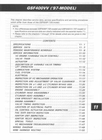
Руководство на английском языке по ремонту мотоциклов Suzuki GSF400VV с 1997 года выпуска.
- Издательство: Suzuki Motor Corporation
- Год издания: —
- Страниц: 49
- Формат: JPG
- Размер: 6,2 Mb
Руководство на английском языке по ремонту мотоциклов Suzuki GSF600.
- Издательство: Suzuki Motor Corporation
- Год издания: 1995
- Страниц: 358
- Формат: PDF
- Размер: 47,7 Mb
Руководство на английском языке по ремонту мотоциклов Suzuki GSF600 и GSF600S.
- Издательство: Suzuki Motor Corporation
- Год издания: 1999
- Страниц: 333
- Формат: PDF
- Размер: 378,2 Mb
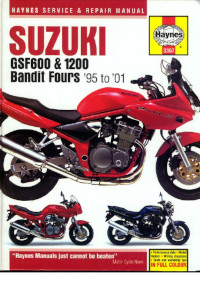
Руководство на английском языке по техническому обслуживанию и ремонту мотоциклов Suzuki GSF600 и GSF1200 Bandit 1995-2001 годов выпуска.
- Издательство: Haynes Publishing
- Год издания: 2001
- Страниц: 281
- Формат: PDF
- Размер: 50,8 Mb
Руководство на английском языке по ремонту мотоциклов Suzuki GSF650, GSF650S и GSX650F.
- Издательство: Suzuki Motor Corporation
- Год издания: 2007
- Страниц: 620
- Формат: PDF
- Размер: 28,9 Mb
Сборник руководств на английском языке по ремонту мотоциклов Suzuki GSF1200 и GSF1200S.
- Издательство: Suzuki Motor Corporation
- Год издания: 1996/1996/2000
- Страниц: -/387/368
- Формат: PDF
- Размер: 118,0 Mb
Руководство на английском языке по ремонту мотоциклов Suzuki GSF1250/GSF1250A/GSF1250S/GSF1250SA.
- Издательство: Suzuki Motor Corporation
- Год издания: 2006
- Страниц: 685
- Формат: PDF
- Размер: 40,2 Mb
