
BA00111D/06/EN/13.14
71261899
Valid as of version
V 1.01.00 (Device software)
Products Solutions Services
Operating Instructions
Proline t-mass 65
Thermal mass flowmeter
6

Proline t-mass 65
Table of contents
1 Document information . . . . . . . . . . . . . . 3
1.1 Document conventions . . . . . . . . . . . . . . . . . . . . . . . 3
2 Safety instructions . . . . . . . . . . . . . . . . . 5
2.1 Designated use . . . . . . . . . . . . . . . . . . . . . . . . . . . . . 5
2.2 Installation, commissioning and operation . . . . . . 5
2.3 Operational safety . . . . . . . . . . . . . . . . . . . . . . . . . . . 6
2.4 Return . . . . . . . . . . . . . . . . . . . . . . . . . . . . . . . . . . . . . 6
2.5 Product safety . . . . . . . . . . . . . . . . . . . . . . . . . . . . . . 6
3 Identification . . . . . . . . . . . . . . . . . . . . . . 7
3.1 Device designation . . . . . . . . . . . . . . . . . . . . . . . . . . 7
3.2 Certificates and approvals . . . . . . . . . . . . . . . . . . 10
3.3 Registered trademarks . . . . . . . . . . . . . . . . . . . . . 10
4 Installation . . . . . . . . . . . . . . . . . . . . . . . 11
4.1 Incoming acceptance, transport and storage . . . 11
4.2 Installation conditions . . . . . . . . . . . . . . . . . . . . . 12
4.3 Installation . . . . . . . . . . . . . . . . . . . . . . . . . . . . . . . 19
4.4 Post-installation check . . . . . . . . . . . . . . . . . . . . . 27
5 Electrical connection. . . . . . . . . . . . . . . 28
5.1 Connecting the remote version . . . . . . . . . . . . . . 28
5.2 Connecting the measuring unit . . . . . . . . . . . . . . 30
5.3 Degree of protection . . . . . . . . . . . . . . . . . . . . . . . 33
5.4 Post-connection check . . . . . . . . . . . . . . . . . . . . . 34
6 Operation . . . . . . . . . . . . . . . . . . . . . . . . 35
6.1 Display and operating elements . . . . . . . . . . . . . 35
6.2 Brief operating instructions for the function matrix
36
6.3 Error messages . . . . . . . . . . . . . . . . . . . . . . . . . . . 38
6.4 Communication . . . . . . . . . . . . . . . . . . . . . . . . . . . 39
9 Accessories . . . . . . . . . . . . . . . . . . . . . . .69
9.1 Device-specific accessories . . . . . . . . . . . . . . . . . . 69
9.2 Communication-specific accessories . . . . . . . . . . 69
9.3 Service-specific accessories . . . . . . . . . . . . . . . . . . 70
10 Trouble-shooting . . . . . . . . . . . . . . . . . .71
10.1 Trouble-shooting instructions . . . . . . . . . . . . . . . 71
10.2 System error messages . . . . . . . . . . . . . . . . . . . . . 72
10.3 Process error messages . . . . . . . . . . . . . . . . . . . . . 76
10.4 Process errors without messages . . . . . . . . . . . . . 76
10.5 Response of outputs to errors . . . . . . . . . . . . . . . . 78
10.6 Spare parts . . . . . . . . . . . . . . . . . . . . . . . . . . . . . . . . 79
10.7 Return . . . . . . . . . . . . . . . . . . . . . . . . . . . . . . . . . . . 86
10.8 Disposal . . . . . . . . . . . . . . . . . . . . . . . . . . . . . . . . . . 86
10.9 Software history . . . . . . . . . . . . . . . . . . . . . . . . . . . 87
11 Technical data. . . . . . . . . . . . . . . . . . . . .88
11.1 Applications . . . . . . . . . . . . . . . . . . . . . . . . . . . . . . 88
11.2 Function and system design . . . . . . . . . . . . . . . . . 88
11.3 Input . . . . . . . . . . . . . . . . . . . . . . . . . . . . . . . . . . . . . 88
11.4 Output . . . . . . . . . . . . . . . . . . . . . . . . . . . . . . . . . . . 89
11.5 Power supply . . . . . . . . . . . . . . . . . . . . . . . . . . . . . . 90
11.6 Performance characteristics . . . . . . . . . . . . . . . . . 90
11.7 Installation . . . . . . . . . . . . . . . . . . . . . . . . . . . . . . . 92
11.8 Environment . . . . . . . . . . . . . . . . . . . . . . . . . . . . . . 92
11.9 Process . . . . . . . . . . . . . . . . . . . . . . . . . . . . . . . . . . . 93
11.10 Mechanical construction . . . . . . . . . . . . . . . . . . . . 95
11.11 Operability . . . . . . . . . . . . . . . . . . . . . . . . . . . . . . . . 97
11.12 Certificates and approvals . . . . . . . . . . . . . . . . . . . 97
11.13 Ordering information . . . . . . . . . . . . . . . . . . . . . . . 99
11.14 Accessories . . . . . . . . . . . . . . . . . . . . . . . . . . . . . . . 99
11.15 Documentation . . . . . . . . . . . . . . . . . . . . . . . . . . . . 99
Index. . . . . . . . . . . . . . . . . . . . . . . . . . . 100
7 Commissioning . . . . . . . . . . . . . . . . . . . 50
7.1 Function check . . . . . . . . . . . . . . . . . . . . . . . . . . . 50
7.2 Switching on the measuring device . . . . . . . . . . 50
7.3 Quick Setup . . . . . . . . . . . . . . . . . . . . . . . . . . . . . . 50
7.4 Configuration . . . . . . . . . . . . . . . . . . . . . . . . . . . . . 61
7.5 Adjustment . . . . . . . . . . . . . . . . . . . . . . . . . . . . . . 65
7.6 Data storage device (HistoROM) . . . . . . . . . . . . . 66
8 Maintenance . . . . . . . . . . . . . . . . . . . . . 67
8.1 External cleaning . . . . . . . . . . . . . . . . . . . . . . . . . 67
8.2 Pipe cleaning . . . . . . . . . . . . . . . . . . . . . . . . . . . . . 67
8.3 Sensor cleaning . . . . . . . . . . . . . . . . . . . . . . . . . . . 67
8.4 Replacing seals . . . . . . . . . . . . . . . . . . . . . . . . . . . 68
8.5 In-situ calibration . . . . . . . . . . . . . . . . . . . . . . . . . 68
8.6 Recalibration . . . . . . . . . . . . . . . . . . . . . . . . . . . . . 68
2 Endress+Hauser
Proline t-mass 65 Document information
1 Document information
1.1 Document conventions
1.1.1 Safety symbols
Symbol Device particularities and document content
“Caution” indicates an action or procedure which, if not performed correctly, can result
«
#
!
Caution!
Warning!
Note!
in incorrect operation or destruction of the device. Comply strictly with the instructions.
«Warning» indicates an action or procedure which, if not performed correctly, can result
in injury or a safety hazard. Comply strictly with the instructions and proceed with care.
«Note» indicates an action or procedure which, if not performed correctly, can have an
indirect effect on operation or trigger an unexpected response on the part of the device.
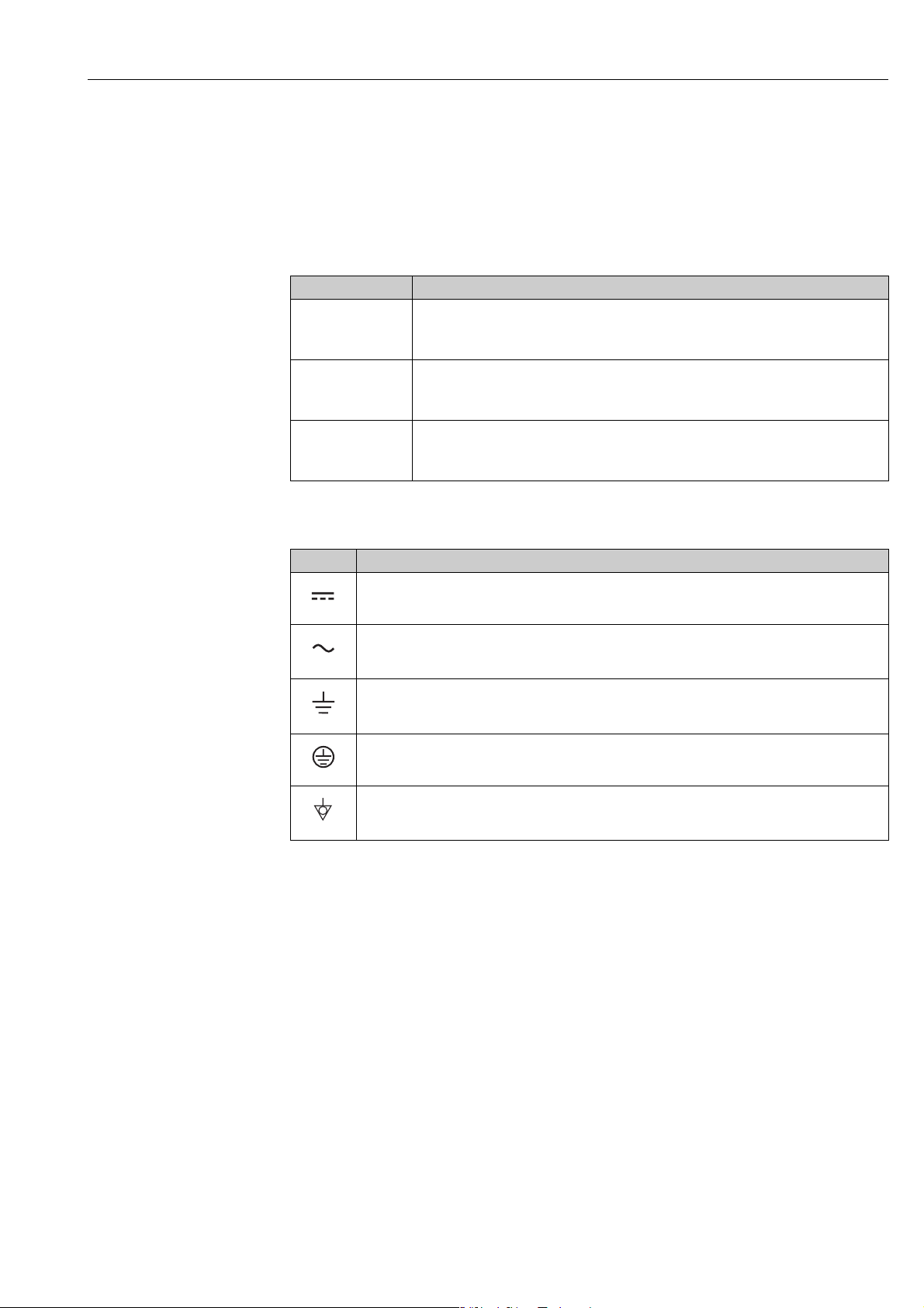
1.1.2 Electrical symbols
Symbol Meaning
Direct current
A terminal at which DC voltage is present or through which direct current flows.
A0011197
Alternating current
A terminal at which alternating voltage (sinusoidal) is present or through which alternating
A0011198
A0011200
A0011199
A0011201
current flows.
Ground connection
A grounded terminal which, as far as the operator is concerned, is grounded via a grounding
system.
Protective ground connection
A terminal which must be connected to ground prior to establishing any other connections.
Equipotential connection
A connection that must be connected to the plant grounding system: This may be a potential
equalization line or a star grounding system depending on national or company codes of practice.
Endress+Hauser 3
Document information Proline t-mass 65
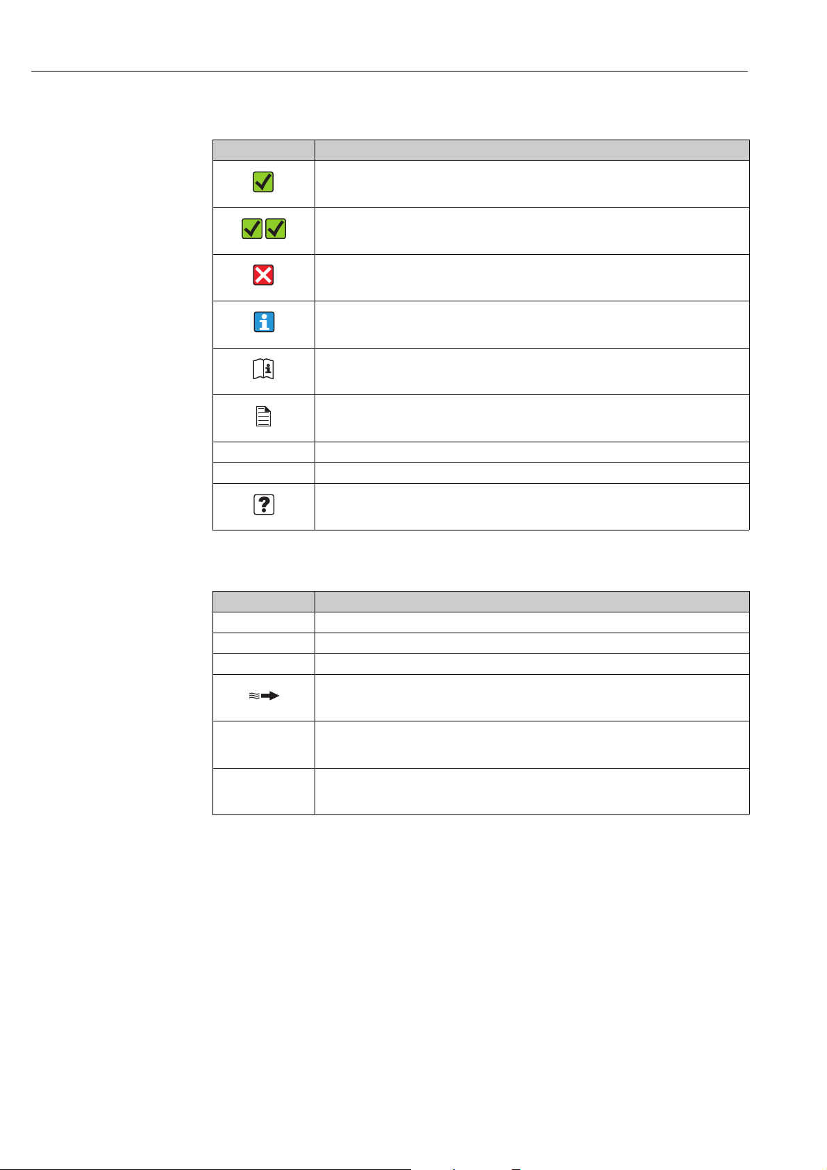
1.1.3 Symbols for types of information
Symbol Meaning
Permitted
Indicates procedures, processes or actions that are permitted.
A0011182
Preferred
Indicates procedures, processes or actions that are preferred.
A0011183
Forbidden
Indicates procedures, processes or actions that are forbidden.
A0011200
Tip
Indicates additional information.
A0011193
Reference to documentation
Refers to the corresponding device documentation.
A0011194
Reference to page
Refers to the corresponding page number.
A0011195
1., 2., 3. etc. Series of steps
Ã
Result of a sequence of actions
Help in the event of a problem
A0013562
1.1.4 Symbols for graphics
Symbol Meaning
1, 2, 3 etc. Item numbers
A, B, C etc. Views
A-A, B-B, C-C etc. Item numbers
Flow direction
A0013441
Hazardous area
Indicates the hazardous area.
A0011187
Safe area (non-hazardous area)
Indicates the non-hazardous area.
A0011187
4 Endress+Hauser

Proline t-mass 65 Safety instructions
2 Safety instructions
2.1 Designated use
The measuring device described in these Operating Instructions is to be used only for
measuring the mass flow rate of gases (e. g. kg, Nm
gas temperature. The measuring device can be configured to measure a standard range of
pure gases or gas mixtures.
Examples:
•Air
•Oxygen
•Nitrogen
• Carbon Dioxide
• Argon, etc.
The use with corrosive, saturated or unclean gases should be treated with caution In such
cases, please contact your Endress+Hauser sales center for clarification. The use with
unstable gases or gases not deemed to be suitable by Endress+Hauser must be avoided. The
measuring device is not designed to be used with liquids or fluids in the liquid phase.
Resulting from incorrect use or from use other than that designated, the operational safety
of the measuring devices can be jeopardized. The manufacturer accepts no liability for
damages being produced from this.
3
Sft3). A t th e same tim e, it also meas ures
2.2 Installation, commissioning and operation
Note the following points:
• Installation, connection to the electricity supply, commissioning, operation and
maintenance of the measuring device must be carried out by trained, qualified specialists
authorized to perform such work by the facility’s owner operator. The specialist must have
read and understood these Operating Instructions and must follow the instructions they
contain.
• Endress+Hauser is willing to assist in clarifying the chemical resistance properties of parts
wetted by special fluids, including fluids used for cleaning. However small changes in
temperature, concentration or the degree of contamination in the process can result in
changes of the chemical resistance properties. Therefore, Endress+Hauser can not
guarantee or accept liability for the chemical resistance properties of the fluid wetted
materials in a specific application. The operator is responsible for the choice of fluid wetted
materials in regards to their in-process resistance to corrosion.
• If carrying out welding work on the piping, the welding unit should not be grounded by
means of the measuring device.
• The installer must ensure that the measuring device is correctly wired in accordance with
the wiring diagrams. The transmitter must be grounded unless special protection
measures have been taken e.g. galvanically isolated power supply SELV or PELV! (SELV =
Safe Extra Low Voltage; PELV = Protective Extra Low Voltage)
• Invariably, local regulations governing the opening and repair of electrical devices apply.
Endress+Hauser 5

Safety instructions Proline t-mass 65
2.3 Operational safety
Note the following points:
• Measuring devices for use in hazardous environments are accompanied by separate
«Ex documentation», which is an integral part of these Operating Instructions. Strict
compliance with the installation instructions and ratings as stated in this supplementary
documentation is mandatory.
The symbol on the front of this supplementary Ex documentation indicates the approval
and the certification body (e.g. 0Europe, 2 USA, 1 Canada).
• Burn hazard! When hot fluid passes through the measuring tube, the surface temperature
of the housing increases. In the case of the sensor, in particular, users should expect
temperatures that can be close to the fluid temperature. If the temperature of the fluid is
high, implement sufficient measures to prevent burning or scalding.
• The measuring device complies with the general safety requirements in accordance with
EN 61010-1, the EMC requirements of IEC/EN 61326, and NAMUR recommendation
NE 21, NE 43 and NE 53.
• The separate document on the Pressure Equipment Directive must be observed for
measuring devices used in Category II or III installations in accordance with the Pressure
Equipment Directive.
• The manufacturer reserves the right to modify technical data without prior notice. Your
Endress+Hauser sales center will supply you with current information and updates to
these Operating Instructions.
2.4 Return
• Do not return a measuring device if it is not absolutely certain that it has been fully cleaned
of all traces of hazardous substances, e.g. substances which have penetrated crevices or
diffused through plastic.
• Costs incurred for waste disposal and injury (burns, etc.) due to inadequate cleaning of the
measuring device will be charged to the owner-operator.
• Refer to the measures on →86.
2.5 Product safety
This measuring device is designed in accordance with good engineering practice to meet
state-of-the-art safety requirements, has been tested, and left the factory in a condition in
which it is safe to operate. It complies with the applicable standards and regulations in
accordance with EN 61010-1 «Safety requirements for electrical equipment for
measurement, control and laboratory use». It can, however, be a source of danger if used
incorrectly or for other than the designated use.
6 Endress+Hauser

Proline t-mass 65 Identification
Order Code:
Ser.No.:
TAG No.:
20-55VAC/16-62VDC
50-60Hz
14VA/8W
IP67/NEMA/Type4X65F25-XXXXXXXXXXXX
12345678901
ABCDEFGHJKLMNPQRST
–20°C (–4°F) < Tamb < +60°C (+140°F)
I-OUT ( HART), f-OUT
Proline t-mass 65
RELAY, RELAY
i
1
2
3
4
7
8
5
6
N12895
3 Identification
3.1 Device designation
The «t-mass 65» measuring device consists of the following components:
• t-mass 65 transmitter
• t-mass F, t-mass I sensors
Two versions are available:
• Compact version: transmitter and sensor form a single mechanical unit.
• Remote version: transmitter and sensor are installed separately.
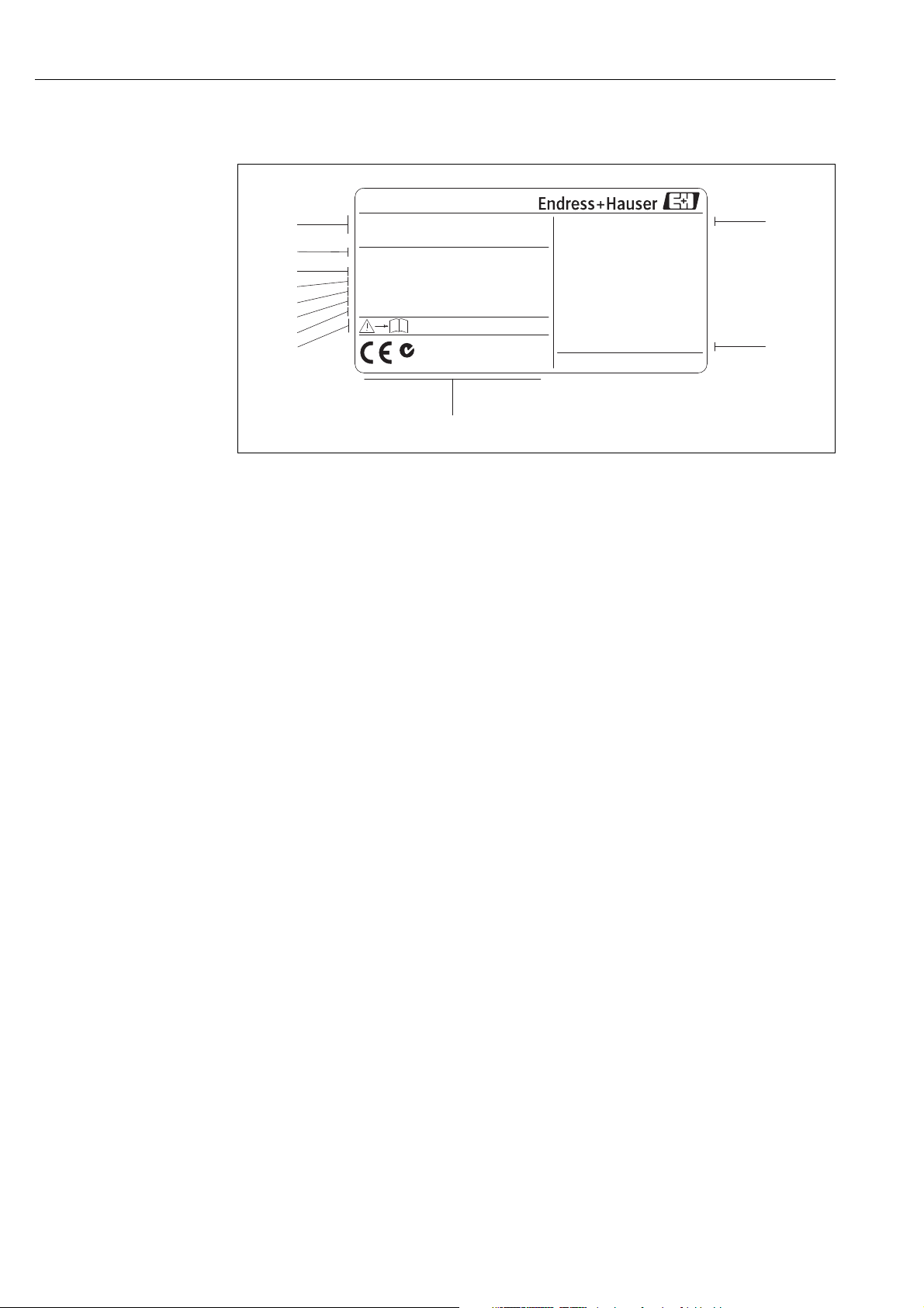
3.1.1 Nameplate of the transmitter
A0005101
Fig. 1: Nameplate specifications for the «t-mass 65» transmitter (example)
1 Order code, serial number: See the specifications on the order confirmation for the meanings of the individual letters and
digits.
2 Power supply, frequency, power consumption
3 Available inputs/outputs:
4 Reserved for information on special products
5 Please refer to operating instructions / documentation
6 Reserved for certificates, approvals and for additional information on device version
7 Ambient temperature range
8 Degree of protection
Endress+Hauser 7
Identification Proline t-mass 65
1
2
4
5
6
7
9
11
10
3
Proline t-mass F
ABCDEFGHIJKLMNOPQRST
TAG-No.:
Ser.No.:
12345678901
Order Code:
IP67 / NEMA/Type 4X
65F50-XXXXXXXXXXXX
P:
T:
Materials:
Seal:
3.1
-0.5…40bar / -7.25…+580 psi gauge
EPDM / PEEK
316/316L/1.4404/Alloy C 22- (2.4602)
-40°C…+100°C / -40°F…+212°F
-20°C(-4°F) <Tamb< +60°C(+140°F)
i
DN50 DIN/EN PN40
N12895
8
3.1.2 Nameplate of the sensor
A0005512
Fig. 2: Nameplate specifications for the «t-mass F» sensor (example)
1 Order code, serial number: See the specifications on the order confirmation for the meanings of the individual letters and
digits.
2 Nominal diameter device
3 Pressure range
4 Temperature range
5 Material of measuring tubes
6Seal material
7 Reserved for information on special products
8 Please refer to operating instructions / documentation
9 Ambient temperature range
10 Degree of protection
11 Reserved for additional information on device version (approvals, certificates)
8 Endress+Hauser
Proline t-mass 65 Identification
Active: 0/4…20mA, RL max. = 700 Ohm
Passive: 4…20mA, max. 30VDC, Ri < 150 Ohm
Passive: 30VDC, 250mA
(HART: RL.min. = 250 OHM)
fmax = 1kHz
3…30VDC, Ri = 5kOhm
f-OUT
I-OUT (HART)
A
P
STATUS-IN
X
f-OUT
Passive: 30VDC, 250mA
fmax = 1kHz
P
Communication:
Drivers:
Device SW: XX.XX.XX
XXXXXXXXXXXXXXXX
Date: 01. MAI 2009
Ex-works / ab-Werk / réglages usine
26(+) / 27(-)
NC:
Versorgung /
Tension d’alimentation
Observer manuel d’instruction
See operating manual
Betriebsanleitung beachten
XXXXXXXXXXXSer.No.:
Supply /
24(+) / 25(-)
22(+) / 23(-)
20(+) / 21(-)
N/L-
PE
A:
NO:
P:
L1/L+
12
319475-00XX
active
passive
normally open contact
normally closed contact
Update 1 Update 2
2
3
1
4
5
6
7
8
9
10
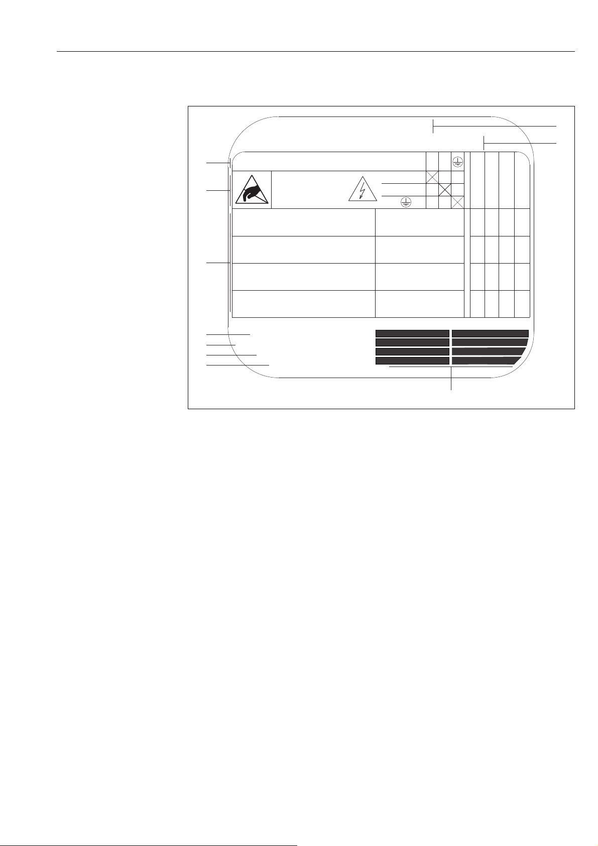
3.1.3 Nameplate for connections
a0013819
Fig. 3: Nameplate specifications for transmitter connections (example)
1 Serial number
2 Possible configuration of current output
3 Possible configuration of relay contacts
4 Terminal assignment, cable for power supply: 85 to 260 V AC, 20 to 55 V AC, 16 to 62 V DC
Terminal No. 1: L1 for AC, L+ for DC
Terminal No. 2: N for AC, L– for DC
5 Signals present at inputs and outputs, possible configuration and terminal assignment (20 to 27),
see also «Electrical values of inputs/outputs», →88
6 Version of device software currently installed
7 Installed communication type, e.g.: HART, PROFIBUS DP, etc.
8 Information on current communication software (Device Revision and Device Description),
e.g.: Dev. 01 / DD 01 for HART
9Date of manufacture
10 Current updates to data specified in points 6 to 9
Endress+Hauser 9

Identification Proline t-mass 65
3.2 Certificates and approvals
This measuring device is designed in accordance with good engineering practice to meet
state-of-the-art safety requirements, has been tested, and left the factory in a condition in
which it is safe to operate. The measuring device complies with the applicable standards and
regulations in accordance with EN 61010-1 «Safety requirements for electrical equipment
for measurement, control and laboratory use» and with the EMC requirements of IEC/EN
61326.
The measuring device described in these Operating Instructions thus complies with the
statutory requirements of the EC Directives. Endress+Hauser confirms successful testing of
the measuring device by affixing to it the CE mark.
The measuring device meets the EMC requirements of the Australian Communications and
Media Authority (ACMA).
3.3 Registered trademarks
KALREZ® and VITON
Registered trademarks of DuPont Performance Elastomers L.L.C., Wilmington, USA
™
AMS
Registered trademark of Emmerson Process Management, St. Louis, USA
®
HART
Registered trademark of HART Communication Foundation, Austin, USA
HistoROM™, S-DAT
Applicator
®
, t-mass
Registered or registration-pending trademarks of businesses in the Endress+Hauser Group
®
®
, T-DAT™, F-CHIP®, FieldCare®, Field XpertTM, FieldCheck®,
®
10 Endress+Hauser
Proline t-mass 65 Installation
4Installation
4.1 Incoming acceptance, transport and storage
4.1.1 Incoming acceptance
On receipt of the goods, check the following points:
• Is the packaging or content undamaged?
• Is the delivery complete and do the delivered goods match your order?
4.1.2 Transport
Observe the following instructions when unpacking and transporting the device to its final
location:
• Transport the measuring device in the container in which it is delivered.
• The covers or caps fitted to the process connections prevent mechanical damage to the
sealing surfaces and contamination in the measuring tube when the unit is being
transported or in storage. Do not remove these covers or caps until immediately before
installation.
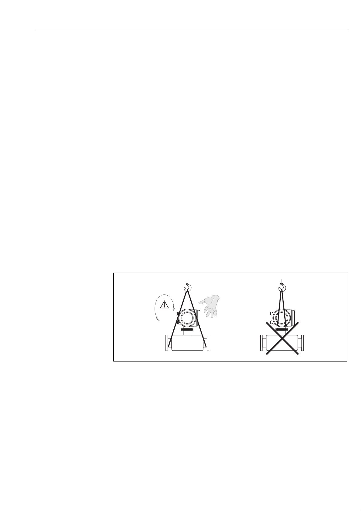
• Do not lift measuring devices of nominal diameters > DN 40 (1½») by the transmitter
housing or the connection housing in the case of the remote version →4. For
transportation purposes, use webbing slings slung round the two process connections. Do
not use chains, as they could damage the housing.
#
Warning!
Risk of injury if the measuring device slips. The center of gravity of the assembled measuring
device might be higher than the points around which the slings are slung.
When transporting, make sure that the measuring device does not unexpectedly turn
around its axis or slip.
A0004294
Fig. 4: Instructions for transporting sensors with > DN 40 (> 1½»)
4.1.3 Storage
Note the following points:
• Pack the measuring device in such a way as to protect it reliably against impact for storage
(and transportation). The original packaging provides optimum protection.
• The permissible storage temperature is: –40 to +80 °C (–40 to +176 °F),
preferably +20 °C (+68 °F).
• Do not remove the protective covers or caps on the process connections until you are ready
to install the device.
• The measuring device must be protected against direct sunlight during storage in order to
avoid unacceptably high surface temperatures.
• Devices delivered with special sealing or bagging for oxygen service must remain sealed or
bagged until ready for installation.
Endress+Hauser 11

Installation Proline t-mass 65
4.2 Installation conditions
Note the following points:
• The thermal dispersion principle is very sensitive to disturbed flow conditions.
• Observe the recommended inlet and outlet requirements.
• Good engineering practice is necessary for the associated pipe work and installation.
• Ensure correct alignment and orientation of the sensor.
• Take measures to reduce or avoid condensation (e.g. install a condensation trap, thermal
insulation, etc.).
• The maximum permitted ambient temperatures →92 and the medium temperature
range →93 must be observed.
• Install the transmitter in a shaded location or use a protective sun shield.
• For mechanical reasons, and in order to protect the pipe, it is advisable to support heavy
sensors.
4.2.1 Dimensions
The dimensions and installation lengths of the sensor and transmitter can be found in the
«Technical Information» for the device in question. This document can be downloaded as a
PDF file from www.endress.com. A list of the «Technical Information» documents available
can be found in the «Documentation» section on →99.
4.2.2 System pressure and pulsating flow
Reciprocating pumps and some compressor systems can create strong changes in process
pressure that can induce spurious internal flow patterns and therefore cause additional
measurement error. These pressure pulses must be reduced by the appropriate measures:
• Use of expansion tanks
• Use of inlet expanders
• Relocate the flowmeter further downstream
In compressed air systems, it is recommended to mount the flowmeter after the filter, dryer
and buffer devices to avoid pulsations and oil/dirt contamination.
Do not mount the flowmeter directly after the compressor outlet.
12 Endress+Hauser
Proline t-mass 65 Installation
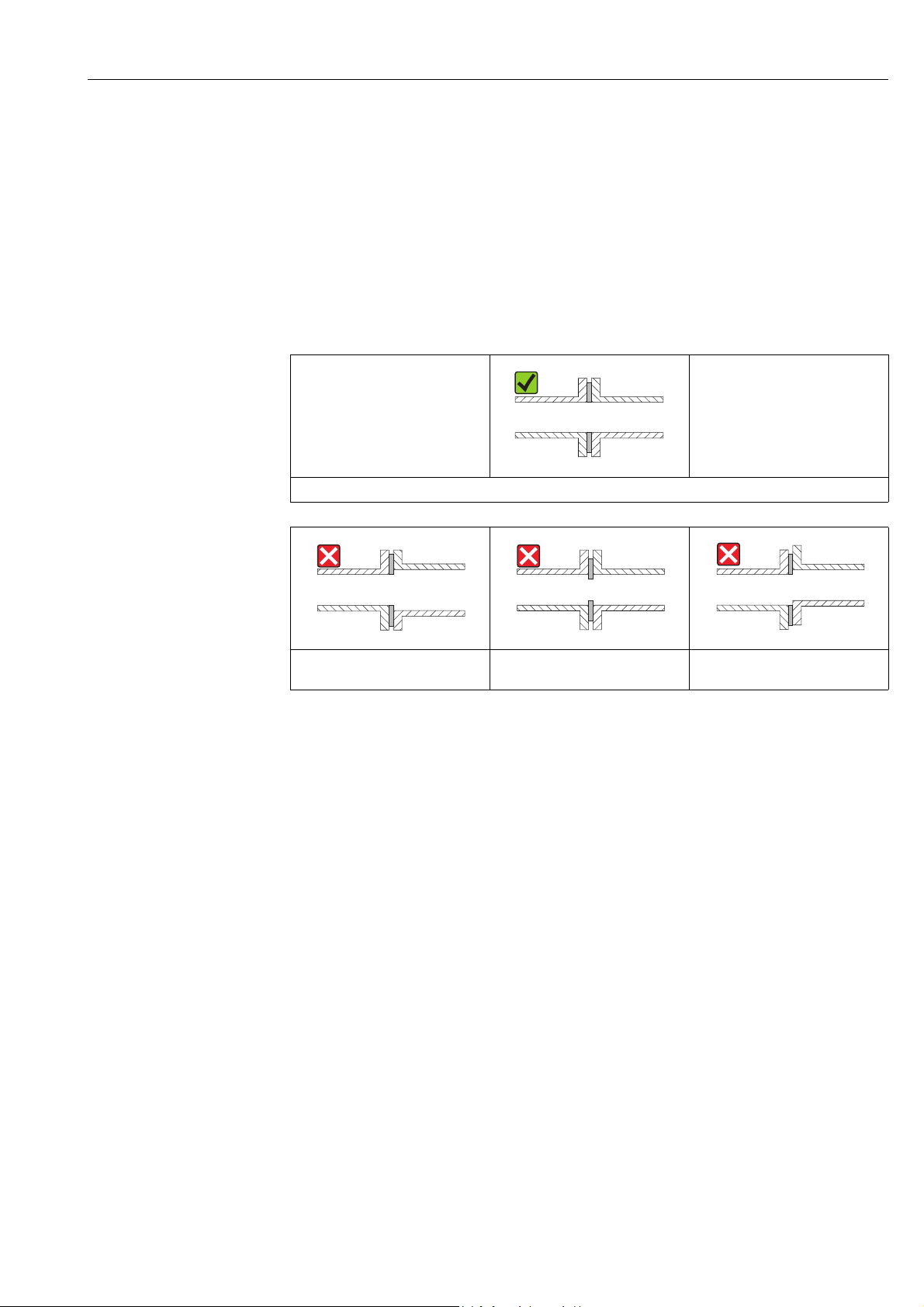
4.2.3 Pipework requirements
Good engineering practice should be followed at all times:
• Correct preparation, welding and finishing techniques
• Correctly sized gaskets
• Correctly aligned flanges and gaskets
• Connecting pipe work should match the internal diameter of the flowmeter. Maximum
pipe diameter mismatch should not exceed:
– 1 mm (0.04 in) for diameters < DN 200 (8″)
– 3 mm (0.12 in) for diameters DN 200 (8″)
Further information is provided in ISO Standard 14511.
A0005103
Correctly aligned flanges and gaskets
A0005104 A0005105 A0005106
Pipe diameter one is not equal pipe
diameter two
Caution!
«
New installations should be free of metallic and abrasive particles to prevent damage to the
Incorrectly sized gaskets Incorrectly aligned flanges and
gaskets
sensing elements on start-up.
Endress+Hauser 13
Installation Proline t-mass 65
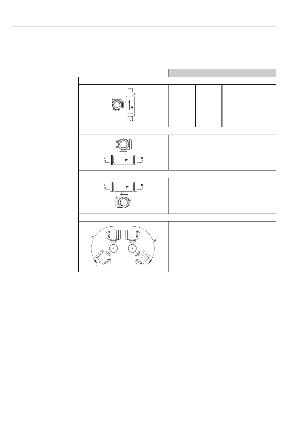
4.2.4 Orientation
Make sure that the direction arrow on the sensor matches the direction of flow through the
pipe.
Flanged sensor Insertion sensor
Vertical orientation
compact
remote
compact
remote
A0013785
Horizontal orientation, transmitter head up
A0013786
Horizontal orientation, transmitter head down
A0013787
Inclined orientation, transmitter head down
m
m
compact/remote
n
compact/remote
o
compact/remote
p
m, n
m
A0009897
= Recommended orientation
= Orientation recommended in certain situations
In the case of saturated or unclean gases, upward flow in a vertical pipe section is preferred
m
to minimize condensation/contamination.
Not recommended if the vibrations are too high or if the installation is unstable.
n
Only suitable for clean/dry gases. Do not mount the sensor from the bottom, on horizontal pipes, if build-up
o
or condensate are likely to be present. Mount the sensor in a position as indicated below
If the gas is very wet or saturated with water (e. g. biogas, undried compressed air), mount in inclined
p
orientation (approx. 135° ±10°).
14 Endress+Hauser
Proline t-mass 65 Installation
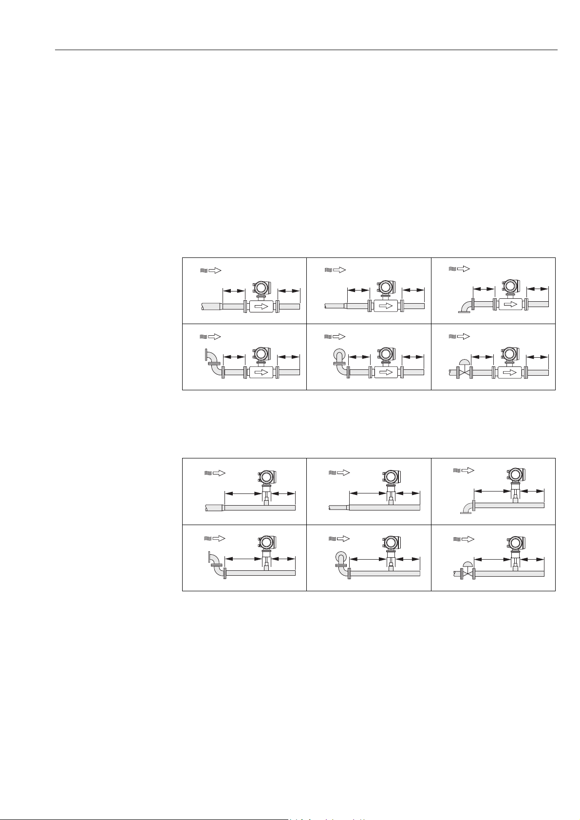
4.2.5 Inlet and outlet runs
The thermal dispersion principle is sensitive to disturbed flow conditions.
As a general rule, the thermal flowmeter should always be installed as far away as possible
from any flow disturbances. For further information ISO Standard 14511.
!
Note!
• Where two or more flow disturbances are located upstream of the meter, the longest
indicated inlet length should prevail. For example if a control valve is additionally mounted
upstream from the measuring device and an elbow on the inlet side, select the
recommended inlet length for control valves: 50 × DN
• For very light gases such as Helium and Hydrogen all upstream distances should be
doubled.
The minimum recommendations for inlet and outlet runs (without flow conditioner) are:
Flanged sensor
1
4
1 = Reduction, 2 = Expansion, 3 = 90° elbow or T-piece, 4 = 2 × 90° elbow,
5 = 2 × 90° elbow (3-dimensional), 6 = Control valve
A0007523
A0007526
2
A0007524
5
A0007527
Insertion sensor
1
4
A0007529
2
A0007530
5
3
A0007525
6
A0007528
3
A0007531
6
Endress+Hauser 15
!
A0007532
1 = Reduction, 2 = Expansion, 3 = 90° elbow or T-piece, 4 = 2 × 90° elbow,
5 = 2 × 90° elbow (3-dimensional), 6 = Control valve or pressure regulator
A0007564
A0007534
Note!
A specially designed perforated plate flow conditioner can be installed if it is not possible to
observe the inlet runs required (→16).

Installation Proline t-mass 65
2 × DN5 — 10 × DN
>8 × DN 5 × DN
5 — 10 × DN
2
1
Outlet runs with pressure measuring points
The pressure measuring point should be installed downstream of the measuring device, so
that there is no potential influence of the pressure transmitter process connection on the
flow entering the measuring point.
A0005114
Fig. 5: Installing a pressure measuring point (PT = pressure transmitter)
Perforated plate flow conditioner
It is recommended to install a perforated plate flow conditioner if the recommended inlet
runs are not available.
!
A0005115
Fig. 6: The figure above illustrates the minimum recommended inlet and outlet runs expressed in multiples of the pipe diameter
1 = Flow conditioner with the flanged sensor, 2 = Flow conditioner with the insertion sensor
using a flow conditioner.
Flow conditioner for use with insertion sensors 65I →69
The well known «Mitsubishi» design is recommended for this application DN 80 mm to
DN 300 mm (3″ to 12″). The flow conditioner must be installed at a distance of 8 × DN
upstream of the sensor. A further 5 pipe diameters minimum inlet run is required upstream
of the actual conditioner itself.
Measured errors can occur depending on disturbances in the inlet run. Therefore it is
advisable to choose inlet runs that are as long as possible.
Note!
In the case of insertion devices, the inlet run selected downstream of the conditioner should
be as long as possible.
16 Endress+Hauser

Proline t-mass 65 Installation
Perforated plate flow conditioners (19 hole) for use with flanged sensor 65F →69
This is a special Endress+Hauser version designed especially for use with the t-mass F sensor
(sizes DN 25 to 100 / 1″ to 4″). The mounting hole patterns and sizing are of a multi-variant
design which means that one plate will fit different flange pressure classes e.g. Cl. 150 and
Cl. 300.
The flow conditioner and gaskets are fitted between the pipe flange and the measuring
device →7. Use only standard bolts which match the flange bolt hole to guarantee that
the flow conditioner is centered correctly.
The alignment notch must also be pointing in the same plane as the transmitter. Incorrect
installation of the flow conditioner will have a small effect on the measurement accuracy.
A0005116
Fig. 7: Flow conditioner mounting arrangement (example)
1=perforated plate flow conditioner, 2= seal/gasket, 3= alignment notch, 4 = alignment in the same plane as the transmitter
Note
• Order the t-mass F sensor and the flow conditioner together to ensure that they are
calibrated together. Joint calibration guarantees optimum performance. Ordering the flow
conditioner separately and using it with the measuring device will further increase
measurement uncertainty.
• The use of conditioners from other suppliers will affect the flow profile and pressure drop
and will have an adverse effect on performance.
• Bolts, nuts, seals, etc. are not included in the scope of supply and must be supplied by the
customer.
Endress+Hauser 17

Installation Proline t-mass 65
4.2.6 Heating
Some applications require suitable measures to avoid heat loss (condensation). Heating can
be electric, e. g. with heated elements, or by means of copper pipes carrying hot water or
steam.
Caution!
«
Risk of electronics overheating! Consequently, make sure that the adapter between sensor
and transmitter and the connection housing of the remote version always remain free of
insulating material.
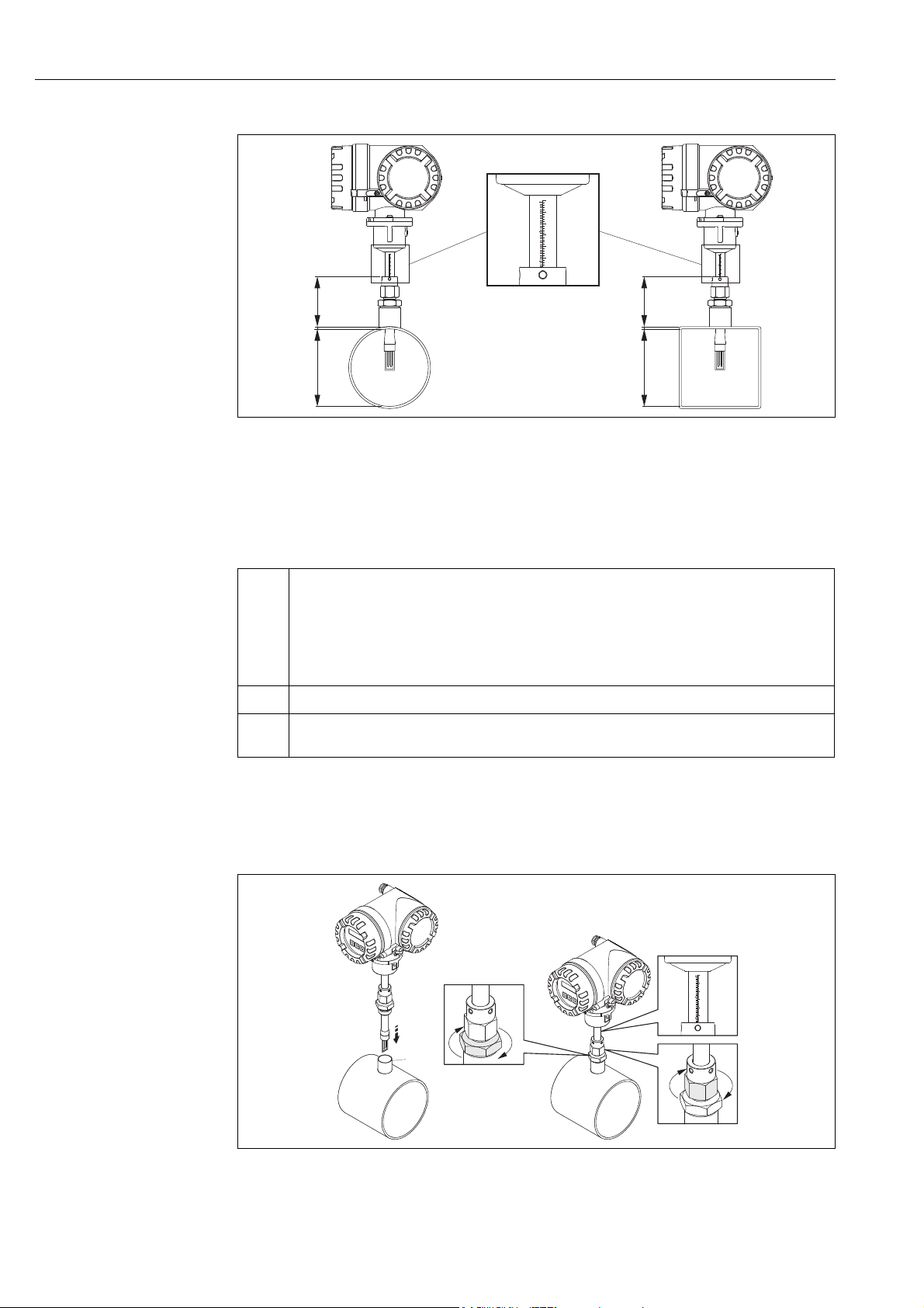
4.2.7 Thermal insulation
If the gas is very wet or saturated with water (e.g. biogas), the piping and sensor housing
should be insulated to prevent water droplets from condensing on the transducer.
Fig. 8: Maximum thermal insulation for t-mass 65F and 65I
a Maximum insulation height for the flanged sensor
b Maximum insulation height for the insertion sensor
4.2.8 Vibrations
Caution!
«
Excessive vibration can result in mechanical damage to the measuring device and its
mounting.
Observe the vibration specification in the technical data section →93
A0005122
18 Endress+Hauser

Proline t-mass 65 Installation
4.3 Installation
4.3.1 Mounting the insertion sensor
The sensor can be mounted into a welding boss or a retractable mounting set. If a retractable
mounting set is being used, then refer to the supplementary documentation delivered with
the mounting set.
Mounting the welding boss
This instruction describes mounting of the Endress+Hauser welding boss. If a welding boss
is already available or a customer-specific one is being used, then go to the next section
«Insertion depth calculation and adjustment.»
!
«
#
Note!
• Take the orientation and inlet and outlet runs into account before mounting the welding
socket →14 ff.
• The welding boss is made of stainless steel 1.4404 (316/316L). Use appropriate welding
technique.
Caution!
• When mounting the fitting to a thin wall duct, use a suitable support bracket for the sensor
and weld the welding boss to a base plate to spread the load. Otherwise, the mounting may
be unstable and the duct wall can be damaged.
Warning!
• These instructions are only applicable to installation in an un-pressurized line, without gas
present and at safe temperatures.
1. Drill or a cut hole of Ø 31.0 mm ± 0.5 mm (1.22 ± 0.019″) in the pipe.
2. Deburr the hole.
3. Fit the edge of the welding boss into the hole, align it vertically and weld it on →9.
A0010098
Fig. 9: Positioning the welding socket on the pipe (or duct)
Insertion depth calculation and adjustment
To ensure optimum measurement performance, the insertion sensor must be installed in the
correct position in the pipe or duct (30% of the internal diameter).
A millimeter and inch scale is provided along the entire length of the sensor tube. This
makes it possible to align the sensor at the right depth.
4. Calculate the insertion depth:
– with the help of the Quick Setup «Sensor» →53 or
Endress+Hauser 19
– using the following dimensions and formulae
Installation Proline t-mass 65
A
B
C
A
B
C
230
220
210
200
190
180
9
8
7
230
220
210
200
190
180
9
8
7
230
220
210
200
190
180
9
8
7
1
3
4
2
230
220
210
200
190
180
9
8
7
A0005118
Fig. 10: Dimensions needed to calculate the insertion depth
A Pipes: internal diameter
Ducts: internal dimension
B Wall thickness
C Dimension from pipe/duct to the compression fitting
!
The following dimensions are required to calculate the insertion depth:
A • For circular pipes: the internal diameter (DN)
B Pipe / duct wall thickness
C Height of the welding nozzle at the pipe/duct including the sensor compression fitting or low pressure
• For rectangular ducts:
– The internal duct height if the sensor is installed vertically
– The internal duct width if the sensor is installed horizontally
Note!
!
Minimum length of dimension A = 80 mm (3.15 in)
mounting set (if used).
Note!
For detailed remarks on calculation refer to Technical Information TI00069D.
• Calculated insertion depth = (0.3 × A) + B + C + 2 mm (0.08 in)
Note down the calculated value.
Fig. 11: Aligning the sensor to the calculated insertion depth
20 Endress+Hauser
A0010001

Proline t-mass 65 Installation
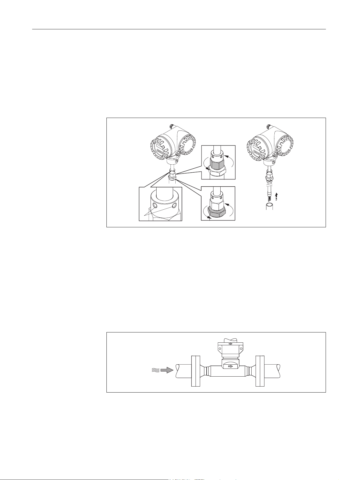
5. Insert the sensor in the nozzle (1) and tighten the lower nut of the compression fitting
(2) finger-tight.
Caution!
«
– NPT thread: use a thread sealing tape or paste
– G 1 A thread: the sealing ring supplied must be installed
6. Tighten the upper nut of compression fitting (3) such that the sensor can still be
adjusted.
7. Read off the calculated insertion depth from the scale and adjust the sensor so that the
value aligns with the upper end of the compression fitting (4).
8. Tighten the lower nut of the compression fitting 1¼ revolutions using a wrench
(42 mm).
Aligning the sensor with the flow direction
A0005117
Fig. 12: Aligning the sensor with the flow direction
9. Check and ensure that the sensor is aligned vertically at a 90° angle on the pipe/duct.
Turn the sensor so that the arrow marking matches the direction of flow.
!
Note!
To ensure optimum exposure of the measuring transducer to the flowing gas stream, the
sensor must not be rotated more than 7° from this alignment.
Fig. 13: Securing the position of the sensor
A0010114
Endress+Hauser 21

Installation Proline t-mass 65
10. Tighten the compression fitting (1) by hand to secure the position of the sensor. Then,
using an open-ended wrench, tighten another 1¼ revolutions in a clockwise direction.
11. Fix the two securing screws (2) (Allen key 3 mm; (1/8″)).
Warning!
#
Observe torque: 4 Nm (2.95 lbf ft)
12. Check that the sensor and transmitter do not turn.
13. Check the measuring point for leaks at the maximum operating pressure.
22 Endress+Hauser
Proline t-mass 65 Installation
4.3.2 Removing the insertion sensor
#
Warning!
• Do not remove the measuring device when it is pressurized! Stop the gas flow and
unpressurize the process pipe.
• In the case of toxic, explosive or flammable gases, the pipe in which the measuring device
is installed must be purged with an inert gas to remove all traces of the gas used.
• Make sure that the process cannot be resumed while removal work is in progress.
• Allow the system and measuring device to cool to a safe temperature
(e.g. <50 °C, (<120 ° F)).
Fig. 14: Removing the insertion sensor
1. Release the securing screws (1).
2. Release the upper nut of compression fitting using a wrench, turning in a
counterclockwise direction (2).
Caution!
«
In the case of vertical installation, do not drop the measuring device into the pipe.
3. Unscrew the lower nut of compression fitting (3) and remove the sensor.
4.3.3 Mounting the flanged sensor
The arrow on the sensor must match with the actual direction of flow through the pipe.
Fig. 15: Mounting in direction of flow
A0011016
A0013663
Endress+Hauser 23
Installation Proline t-mass 65
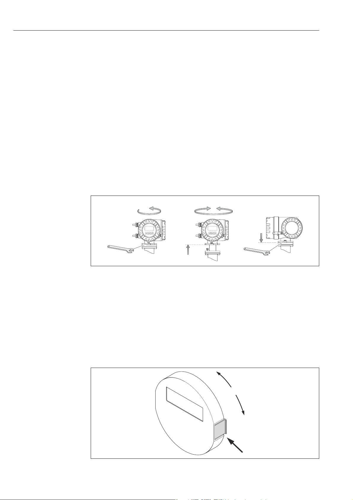
4.3.4 Turning the transmitter housing
Turning the aluminum field housing
#
Warning!
The rotating mechanism for measuring devices for hazardous areas Zone 1 (ATEX/IEC Ex)
or Clas s I Div . 1 ( FM/C SA) is dif fere nt to that described here. The procedure for turning these
housings is described in the Ex-specific documentation →99.
1. Loosen the two securing screws.
Caution!
«
Special screw! Do not loosen screw completely or replace with another screw.
Use only original Endress+Hauser parts.
1. Turn the bayonet catch as far as it will go.
2. Carefully lift the transmitter housing as far as it will go.
3. Turn the transmitter housing to the desired position (max. 2 × 90° in either direction).
4. Lower the housing into position and re-engage the bayonet catch.
5. Retighten the two securing screws.
A0004302
Fig. 16: Turning the transmitter housing (aluminum field housing)
4.3.5 Turning the local display
1. Unscrew cover of the electronics compartment from the transmitter housing.
2. Press the side latches on the display module and remove the module from the
electronics compartment cover plate.
3. Rotate the display to the desired position (4 × 45 ° in both directions), and reset it onto
the electronics compartment cover plate.
4. Screw the cover of the electronics compartment firmly back onto the transmitter
housing.
Fig. 17: Turning the local display (field housing)
24 Endress+Hauser
A0003236

Proline t-mass 65 Installation
a
b
c
90 (3.54)
35 (1.38)
192 (7.56)
81.5 (3.2)
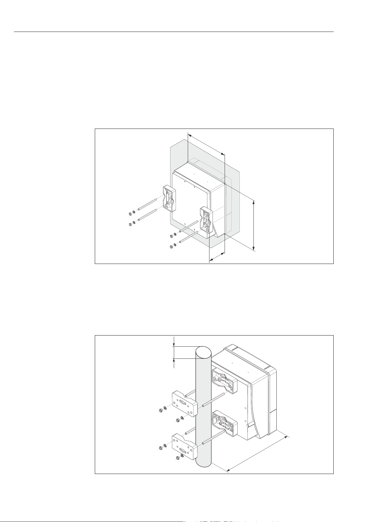
4.3.6 Installing the wall-mount transmitter housing
There are various ways of installing the wall-mount transmitter housing:
• Mounted directly on the wall
• Installation in control panel →26 (separate mounting set, accessories) →69
•Pipe mounting →26 (separate mounting set, accessories →69)
Caution!
«
• The ambient temperature may not exceed the permissible range of –20 to +60 °C
(-4 to +140 °F), optionally –40 to +60 °C (–40 to +140 °F), at the mounting location.
• Install the device in a shady location. Avoid direct sunlight on the display.
• Always install the wall-mount housing in such a way that the cable entries are pointing
down.
Mounted directly on the wall
1. Drill the holes as illustrated in the diagram.
2. Remove the cover of the connection compartment (a).
3. Push the two securing screws (b) through the appropriate bores (c) in the housing.
– Securing screws (M6): max. Ø 6.5 mm (0.26 inch)
– Screw head: max. Ø 10.5 mm (0.41 inch)
4. Secure the transmitter housing to the wall as indicated.
5. Screw the cover of the connection compartment (a) firmly onto the housing.
Fig. 18: Engineering unit mm (in)
A0001130
Endress+Hauser 25
Installation Proline t-mass 65
245 (9.65)
~110 (~4.33)
210 (8.27)
+0.5 (+0.019)
–0.5 (–0.019)
+0.5 (+0.019)
–0.5 (–0.019)
Ø 20…70
(Ø 0.79…2.75)
~ ~ 6.1)155 (
Installation in control panel
1. Prepare the opening in the panel as illustrated in the diagram.
2. Slide the housing into the opening in the panel from the front.
3. Screw the fasteners onto the wall-mount housing.
4. Screw threaded rods into holders and tighten
until the housing is solidly seated on the panel wall. Afterwards, tighten the locking
nuts.
Additional support is not necessary.
Fig. 19: Engineering unit mm (in)
Pipe mounting
The assembly should be performed by following the instructions in the diagram.
Caution!
«
If a warm pipe is used for installation, make sure
that the housing temperature does not exceed the max. permitted value of +60 °C (+140 °F).
A0001131
Fig. 20: Engineering unit mm (in)
26 Endress+Hauser
A0001132
Proline t-mass 65 Installation
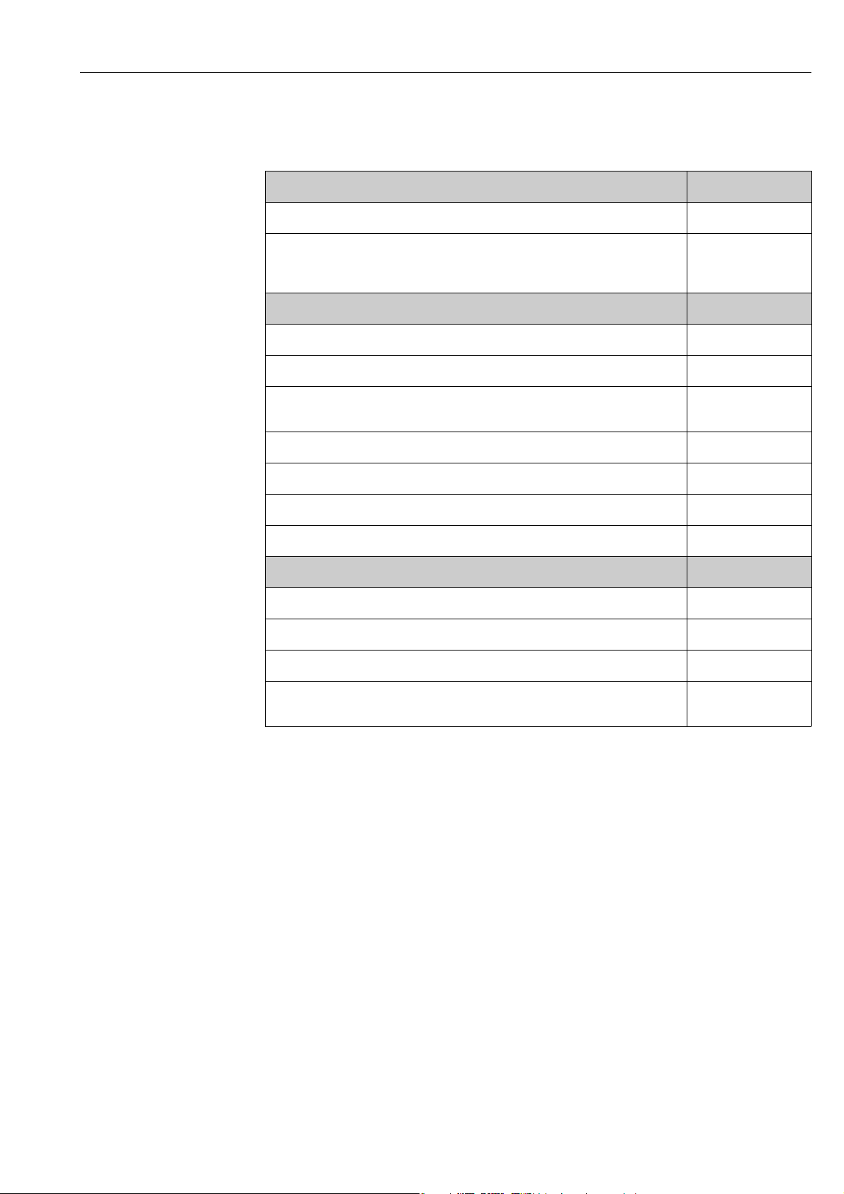
4.4 Post-installation check
Perform the following checks after installing the measuring device in the pipe:
Device condition and specifications Notes
Is the measuring device undamaged (visual inspection)? –
Does the device correspond to specifications at the measurement point, including
process temperature and pressure, ambient temperature, measuring range, etc.?
Check the name plate.
Installation Notes
Correct alignment of pipe/gasket/flowmeter body? →13
Professional installation, e.g. correct pipe internal diameter, correctly sized gaskets? →13
Is the position chosen for the sensor correct, in other words suitable for sensor type,
fluid properties and fluid temperature?
Is there sufficient upstream and downstream pipe sensor? →15
Correct installation of flow conditioner (if fitted)? →16
Does the arrow on the sensor match the direction of flow through the pipe? →14
Correct sensor depth (insertion sensor only)? →19
Process environment/process conditions Notes
Is the measuring device protected against moisture and direct sunlight? –
Is the measuring device protected against overheating? →18
→7
→14
Is the measuring device protected against excessive vibration? →18, →93
Check gas conditions (e. g. purity, dryness, cleanliness) Select suitable
orientation →14
Endress+Hauser 27
Electrical connection Proline t-mass 65
N
i
c
h
t
u
n
t
e
r
S
p
a
n
n
u
n
g
ö
f
f
n
e
n
K
e
e
p
c
o
v
e
r
t
i
g
h
t
w
h
i
l
e
c
i
r
c
u
i
t
s
a
r
e
a
l
i
v
e
N
e
p
a
s
o
u
v
r
i
r
l
’
a
p
p
a
r
e
i
l
s
o
u
s
t
e
n
s
i
o
n
K
e
e
p
c
o
v
e
r
t
i
g
h
t
w
h
i
l
e
c
i
r
c
u
i
t
s
a
r
e
a
l
i
v
e
AB
C
D
41 42 43 44
GND
6…
10V
COMMS
+
—
+
—
GND
COMMS
—
++
41 42 43 44
6…
10V
5 Electrical connection
#
!
!
#
Warning!
When connecting Ex-certified measuring devices, see the notes and diagrams in the Exspecific supplement to these Operating Instructions. Please do not hesitate to contact your
Endress+Hauser sales center if you have any questions.
Note!
The measuring device does not have an internal power isolation switch. Therefore provide
an isolation switch or circuit breaker which can be used to disconnect the power supply to
the measuring device.
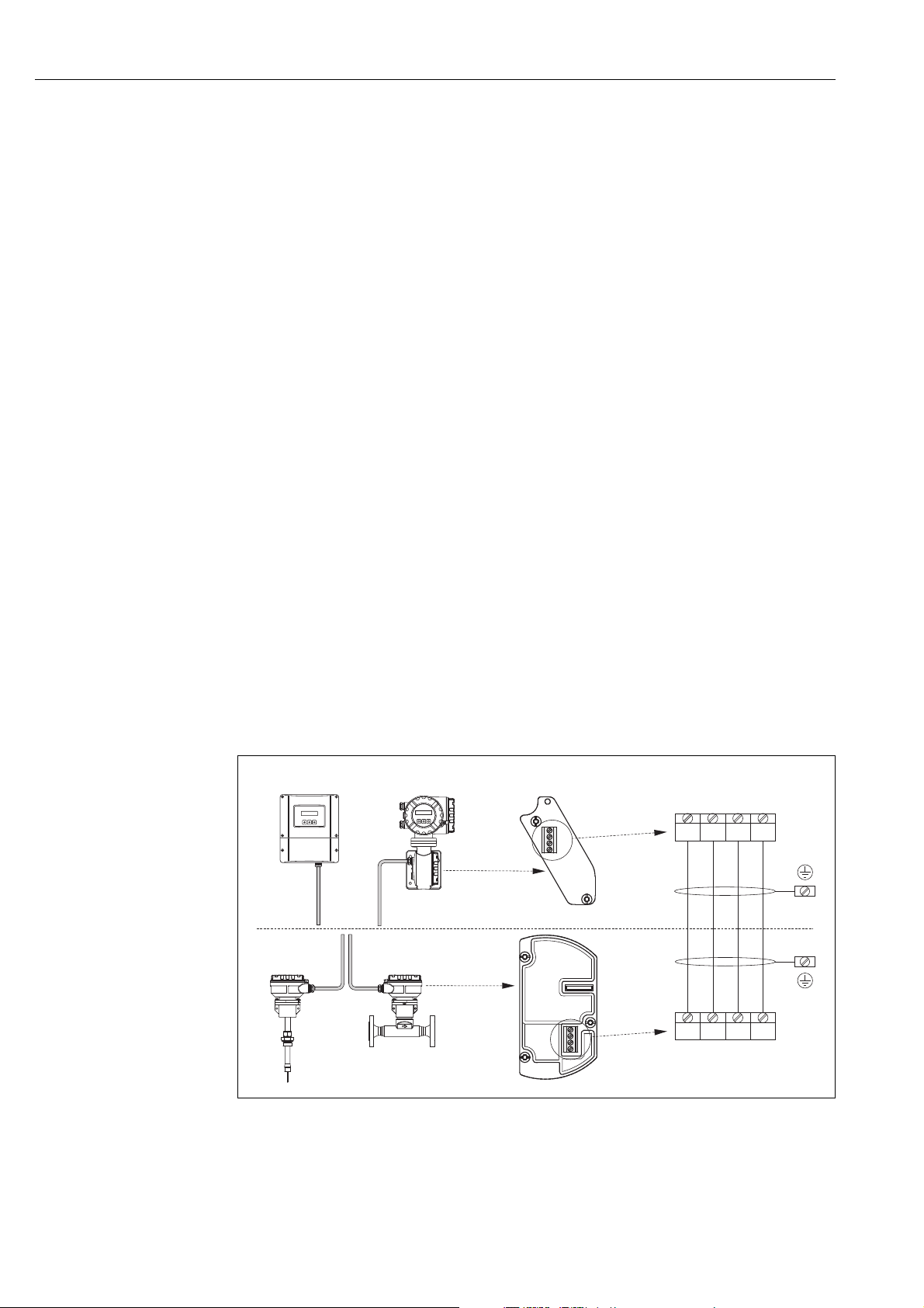
5.1 Connecting the remote version
Note!
A cable is not supplied for the remote version.
5.1.1 Connecting the connecting cable for sensor/transmitter
Warning!
• After removing the electronics cover, there is a risk of electric shock as shock protection is
removed! Switch off the measuring device before removing internal covers.
• Risk of electric shock. Connect the protective earth to the ground terminal on the housing
before the power is supplied.
1. Remove the connection compartment cover by loosening the fixing screws on the
transmitter and sensor housing.
2. Feed the connecting cable through the appropriate cable entry.
3. Establish the connections between sensor and transmitter in accordance with the
wiring diagram (→21 or see wiring diagram in screw cap; wire cross-section:
max. 2.5 mm² (14 AWG)).
4. Screw the connection compartment cover back onto the sensor or transmitter housing.
Fig. 21: Connecting the remote version
A Wallmount housing; Non-hazardous area and zone 2 (ATEX II3G, FM/CSA)
B Field housing; Zone 1 (ATEX II2GD, IECEx, FM/CSA)
C Remote sensor insertion
D Remote sensor flanged
Wire colors (when supplied by Endress+Hauser):
Terminal no. 41 = white; 42 = brown; 43 = green; 44 = yellow
see separate «Ex documentation»
see separate «Ex documentation»
A0005123
28 Endress+Hauser

Proline t-mass 65 Electrical connection
5.1.2 Cable specification, connecting cable
A cable with the following specifications must be used for the remote version:
• 2 × 2 × 0.5 mm² (AWG 20) PVC cable with common shield (2 twisted pairs)
• Conductor resistance: 40 /km ( 131.2 /1000 ft)
•Operating voltage: 250 V
• Temperature range: –40 to +105 °C (–40 to +221 °F)
• Overall nominal diameter: 8.5 mm (0.335″)
• Maximum cable length: 100 m (328 feet)
!
Note!
• The cable must be installed securely to prevent movement
• The cable should be of sufficient diameter to provide adequate sealing of the compression
fitting →90.
Endress+Hauser 29

Electrical connection Proline t-mass 65
5.2 Connecting the measuring unit
5.2.1 Terminal assignment
Electrical values for inputs
→88
Electrical values for outputs
→89
Terminal No. (inputs/outputs)
Order variant 20 (+) / 21 (–) 22 (+) / 23 (–) 24 (+) / 25 (–) 26 (+) / 27 (–)
Fixed communication boards (permanent assignment)
65F**-***********A
65I-*************A
65F**-***********B
65I-*************B
65F**-***********R
65I-*************R
65F**-***********S
65I-*************S
65F**-***********T
65I-*************T
65F**-***********U
65I-*************U
Flexible communication boards
65F**-***********C
65I-*************C
65F**-***********D
65I-*************D
65F**-***********E
65I-*************E
65F**-***********L
65I-*************L
65F**-***********2
65I-*************2
65F**-***********4
65I-*************4
65F**-***********5
65I-*************5
65F**-***********6
65I-*************6
65F**-***********8
65I-*************8
Relay output Relay output Frequency output
Relay output 2 Relay output 1 Frequency output Current output, HART
Status input Relay output Frequency output Current output, HART
Status input Relay output Current output 2
Status input Relay output 2 Relay output 1 Current output, HART
Relay output Current output 2 Frequency output
Current input Relay output Frequency output Current output, HART
Status input Current input Frequency output Current output, HART
Status input Current input Current output 2 Current output, HART
Status input Frequency output Current output 2 Current output, HART
— — Frequency output
—
—
—
—
Current output 2
Ex i, active
Frequency output
Ex i, passive
Frequency output
Ex i, passive
Current output 2
Ex i, passive
Current output
HART
Current output
HART
Current output 1,
Ex i, active, HART
Current output, Ex i,
active, HART
Current output, Ex i,
passive, HART
Current output 1,
Ex i, passive, HART
Current output 1,
HART
Current output 1,
HART
30 Endress+Hauser
Proline t-mass 65 Electrical connection
b
b
c
d
a
a
2
1
–27
–25
–23
–21
+ 26
+ 24
+ 22
+ 20
L1 (L+)
N (L-)
g
f
e
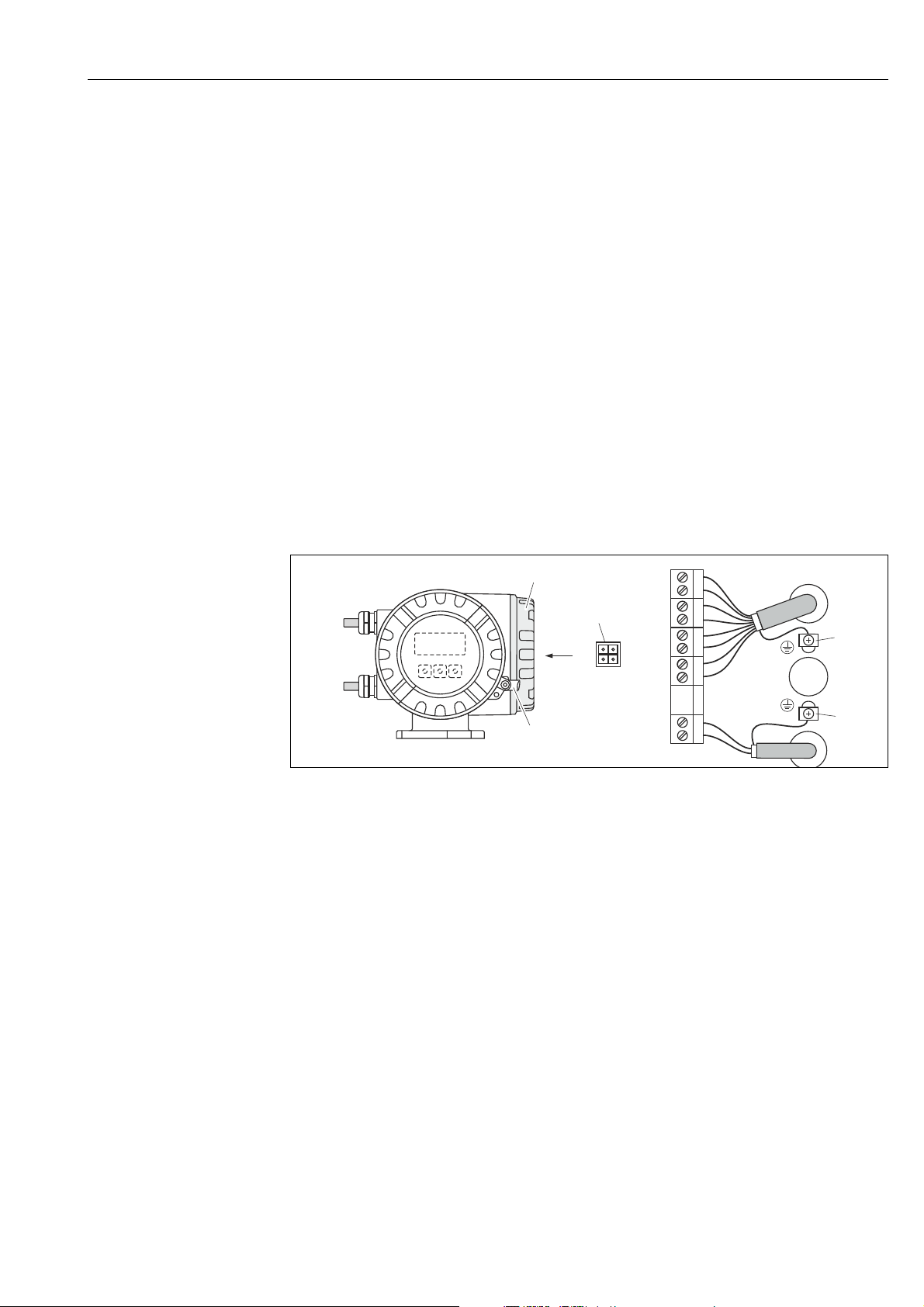
5.2.2 Transmitter connection
#
Warning!
• Risk of electric shock. Switch off the power supply before opening the measuring device.
Never mount or wire the measuring device while it is connected to the power supply.
Failure to comply with this precaution can result in irreparable damage to the electronics.
• Risk of electric shock. Connect the protective earth to the ground terminal on the housing
before the power supply is applied unless special protection measures have been taken
(e.g. galvanically isolated power supply SELV or PELV).
• Compare the specifications on the nameplate with the local supply voltage and frequency.
The national regulations governing the installation of electrical equipment also apply.
1. Unscrew the connection compartment cover (f) from the transmitter housing.
2. Feed the power supply cable (a) and the signal cable (b) through the appropriate
cable entries.
3. Perform wiring:
– Wiring diagram (aluminum housing) →22
– Wiring diagram (wall-mount housing) →23
– Terminal assignment →30
4. Screw the cover of the connection compartment (f) back onto the transmitter housing.
Connecting the aluminum field housing
A0004582
Fig. 22: Connecting the transmitter (aluminum field housing). Wire cross-section: max. 2.5 mm²(14 AWG)
a Cable for power supply: 85 to 260 V AC, 20 to 55 V AC, 16 to 62 V DC
Terminal No. 1: L1 for AC, L+ for DC
Terminal No. 2: N for AC, L– for DC
b Signal cable: Terminals Nos. 20-27 →30
c Ground terminal for protective earth
d Ground terminal for signal cable shield
e Service adapter for connecting service interface FXA193 (FieldCheck, FieldCare)
f Cover of the connection compartment
gSecuring clamp
Endress+Hauser 31
 Loading…
- Сертификаты на взрывозащиту
-
ATEX, FM, CSA, NEPSI
- Безопасность изделия
-
Международные сертификаты на использование во взрывоопасных зонах Маркировка CE, C-Tick, EAC
- Диапазон номинальных диаметров
-
DN 80…1500
- Измеряемые параметры
-
Массовый расход, температура, объемный расход, расход энергии
- Макс. погрешность измерения
-
Газ: 1,5% ИЗМ (10…100% ВПД), 0,15% ВПД (1…10% ВПД)
- Диапазон измерения
-
20…720000 кг/ч
- Макс. рабочее давление
-
-0,5…20 бар изб.
- Диапазон температур продукта
-
-40°C…+130°C
- Диапазон окружающей температуры
-
-20 °C…+60 °C
Опция: -40 °C…+60 °C - Дисплей/Настройка
-
Жидкокристаллический: с подсветкой, 2-строчный, по 16 символов на строку
Настройка посредством локального дисплея и управляющего ПО - Выходные сигналы
-
4…20 мА HART (активный/пассивный по выбору), импульсный, частотный, сигнал состояния
- Входные сигналы
-
4…20 мА, входной сигнал состояния
- Цифровая связь
-
Profibus DP, Profibus PA, Foundation Fieldbus, Modbus
- Источник питания
-
85…260 В перем. тока, 45…65 Гц
20…55 В перем. тока, 45…65 Гц
16…62 В пост. тока
ВСЕРОССИЙСКИЙ НАУЧНО-ИССЛЕДОВАТЕЛЬСКИЙ ИНСТИТУТ МЕТРОЛОГИЧЕСКОЙ СЛУЖБЫ
(ФГУП «ВНИИМС»)
УТВЕРЖДАЮ
Заместитель директора
по производственной метрологии

Государственная система обеспечения единства измерении РАСХОДОМЕРЫ-СЧЕТЧИКИ ТЕПЛОВЫЕ T-MASS Методика поверки
МП 35688-13
С изменением №1
МОСКВА
2017
1. ВВЕДЕНИЕ
-
1.1. Настоящий документ распространяется на расходомеры-счетчики тепловые t-mass (далее расходомеры) фирмы Endress+Hauser Flowtec AG (Швейцария) при использовании их в сферах распространения государственного метрологического контроля и надзора, и устанавливает методы и средства их первичной и периодической поверок при выпуске из производства и после ремонта.
-
1.2. Межповерочный интервал — не более 3 лет.
-
1.3. Методика описывает два метода поверки:
-
— проливной;
-
— имитационный.
2. ПРОЛИВНОЙ МЕТОД ПОВЕРКИ
2.1 Операция поверки
-
2.1.1. При проведении поверки выполняют следующие операции:
-
— внешний осмотр (п. 2.6.1.);
-
— проверка герметичности (для фланцевых расходомеров) (п. 2.6.2.);
-
— опробование (п. 2.6.3.);
-
— проверка идентификационных данных программного обеспечения (ПО) расходомера (п. 2.6.4);
-
— определение метрологических характеристик (п. 2.6.5.).
2.2 Средства поверки
2.2.1 При проведении поверки применяют следующие эталоны и испытательное оборудование:
-установка эталонная расходомерная газовая, максимальный расход (при Ду = 100 мм) не менее 1500 м3/ч, погрешность ±0,35 %;
-термопреобразователь для измерений температуры газа в расходомерной газовой установке, с диапазоном измерений от 0 до 100 °C и абсолютной погрешностью не более ±1 °C;
-датчик давления для измерений избыточного давления газа в расходомерной газовой установке с относительной погрешностью не более ±0,25 %;
-частотомер электронно-счетный 43-49А амплитудой до 50 В и частотой от 0 до
10 кГц;
-ампервольтметр Р386, диапазон измерений от 0,1 до 10 В, погрешность ±0,05 %; -термометр типа ТЛ-4 с пределами измерения до 100 °C и ценой деления 0,5 °C, по ТУ 25-2021.003-88;
-пневматический пресс с контрольным манометром классом точности не более 0,4; -источник постоянного тока напряжением 24 В, переменного тока 220 В частотой 50 Гц;
-психрометр аспирационный типа М-34 по ТУ 25-1607.054-85 ТУ 52.07-(ГРПИ.405 132.001)-92;
-образцовый манометр типа МО с пределами измерений от 0 до 1,0 МПа класса точности 0,4;
-барометр-анероид М-67 по ТУ 2504-1797-75.
-
2.2.2. Используемые эталоны должны быть поверены, иметь действующие свидетельства о поверке.
-
2.2.3. Допускается использовать другие эталоны с характеристиками не хуже указанных в п.2.2.1. Соотношение основных погрешностей поверочной установки, эталонов по поверяемому параметру расходомера не должно превышать 1:3.
2.3 Требования безопасности
-
2.3.1. При проведении поверки соблюдают требования безопасности определяемые:
-
— правилами безопасности труда и пожарной безопасности действующими на поверочной установке;
-
— правилами безопасности при эксплуатации используемых эталонов, испытательного оборудования и поверяемого расходомера приведенными в эксплуатационной документации.
2.3.2 Монтаж электрических соединений должен производиться в соответствии с ГОСТ 12.3.032-84 и «Правилами устройства электроустановок» (раздел VII).
-
2.3.2. К поверке допускают лиц, имеющих квалификационную группу по технике безопасности не ниже II в соответствии с «Правилами техники безопасности при эксплуатации электроустановок потребителей», изучивших руководство по эксплуатации на расходомер и настоящий документ.
2.4 Условия поверки
-
2.4.1. При проведении поверки соблюдают следующие условия:
-
— поверочная среда — воздух КИП;
-
— температура окружающего воздуха 20 ± 5 °C;
-
— температура измеряемой среды 15…25 °C;
-
— относительная влажность воздуха 30…80 %;
-
— атмосферное давление 86… 107 кПа.
-
2.4.2. Изменение температуры поверочной среды во время поверки не должно превышать 5 °C.
-
2.4.3. Изменение давления поверочной среды во время поверки не должно превышать 0,1 кПа.
2.5 Подготовка к поверке
-
2.5.1. Поверяемый расходомер типов F, А (фланцевый) устанавливают на поверочной установке, поверяемый расходомер типов I, В (погружной) устанавливают в специальную вставку (см. приложение А), которую монтируют на поверочной установке. При монтаже соблюдают требования прямых участков, указанные в руководстве по эксплуатации поверяемого расходомера. Согласно руководству по эксплуатации расходомер подготавливают к работе и с помощью следующих настроек настраивают его на измерение расхода воздух.
Для t-mass 65 F/I алгоритм настройки следующий:
-
— GAS MIXTURE (Смесь газов) -+ NUMBER OF GAS COMPONENTS (число компонентов газа)= 1;
-
— GAS MIXTURE (Смесь газов) -+ GAS TYPE 1 (Газ №1) = AIR (Воздух).
Для t-mass 150 A/В алгоритм настройки описан ниже:
-
— SETUP (Настройки) —> SELECT GAS TYPE (Выбрать тип газа) AIR (Воздух).
-
2.5.2. Проводят проверку токового выхода. Для этого задают в ячейке «проверка токового выхода» («simulation current») не менее трёх из имеющихся токовых значений в произвольном порядке.
Абсолютную погрешность А по токовому сигналу рассчитывают по формуле
Az = |Zs|-|Zp|
где
1Р — значение тока на выходе расходомера в мА;
Is — проверочное значение тока в мА,
Расходомер считают выдержавшим проверку по токовому выходу, если значение погрешности не превышает значения допустимой абсолютной погрешности токового сигнала
|az|<|a’z|,
где значение допустимой абсолютной погрешности токового сигнала А расходомера указанно в руководстве по эксплуатации соответственно его исполнению.
-
2.5.3. Проводят проверку частотного выхода. Для этого задают в ячейке «проверка частотного сигнала» («simulation frequency») не менее трёх из имеющихся значений частоты в произвольном порядке.
Расходомер считают выдержавшим проверку по частотному выходу, если значение частоты на выходе расходомера совпадает с заданным.
-
2.6. Проведение поверки
2.6.1. Внешний осмотр.
-
2.6.1.1. При внешнем осмотре устанавливают:
-
— на расходомере отсутствуют механические повреждения, препятствующие его применению;
-
— надписи и обозначения на расходомере четкие и соответствуют требованиям эксплуатационной документации;
-
— комплектность расходомера соответствует указанной в документации;
-
— соответствие исполнения расходомера его маркировке.
-
2.6.1.2. Расходомер не прошедший внешний осмотр, к поверке не допускают.
2.6.2. Проверка герметичности расходомера (для фланцевого расходомера 65F, А 150).
-
2.6.2.1. Проверку герметичности проводят путем создания в полости первичного преобразователя расходомера давления 0,6 МПа при помощи пневматического пресса. Время выдержки под давлением не менее 15 мин.
-
2.6.2.2. Расходомер считают выдержавшим проверку, если в течение 15 минут не наблюдается падение давления по манометру.
2.6.3. Опробование.
2.6.3.1.Опробуют расходомер на поверочной установке путем увеличения/уменыпения расхода газа в пределах рабочего диапазона измерений.
-
2.6.3.2. Результаты опробования считают удовлетворительными, если при увеличе-нии/уменыпении расхода воздуха соответствующим образом изменялись показания на дисплее расходомера, на мониторе компьютера, контроллера, выходной измерительный сиг-нал/сигналы. Величины расхода контролируют по показаниям расходомера и установки.
-
2.6.3.3. Результаты опробования считаются положительными, если расход воздуха регулируется в пределах согласно эксплуатационной документации.
2.6.4. Проверка идентификационных данных программного обеспечения (ПО) расходомера.
При запуске расходомера номера версий программного обеспечения должны выводиться на экран преобразователя путем следующих команд в меню прибора:
DIAGNOSTICS DEVICE INFO FIRMWARE VERSION.
Также номера версий ПО расходомера должны отображаться на дисплее преобразователя при его включении как неактивные, не подлежащие изменению.
Доступ к цифровому идентификатору ПО (контрольной сумме исполняемого кода) не возможен.
Результаты поверки считаются положительными, если отображаются следующие идентификационные данные.
|
Наименование программного обеспечения |
Идентификационное наименование программного обеспечения |
Номер версии (идентификационный номер) программного обеспечения |
|
t-mass 65 |
71137565 |
не ниже Vl.0y.zz |
|
t-mass 150 |
71185873 |
не ниже V01.0y.zz |
2.6.5. Определение метрологических характеристик.
-
2.6.5.1.Погрешность расходомера определяют сравнением значения приведенного к стандартным условиям объема воздуха Vp, измеренного расходомером в рабочем диапазоне измерений расхода в трех точках 0,1 Qmax, 0,3Qmax и 0,5Qmax, со значениями приведенного к стандартным условиям объема воздуха Vy, измеренного при помощи расходомерной газовой установки. Измерение в каждой точке проводят однократно. Здесь Qmax — верхний предел измерений расходомера по воздуху при стандартных условиях (в калиброванном диапазоне), указанный в технической документации на расходомер (для погружного расходомера — соответствующий диаметру используемой вставки).
-
2.6.5.2.Если расходомерная установка поверена по объему при рабочих условиях, то заданный расход Q’n измеренный установкой при заданном расходе объем V’y приводят к стандартным условиям по следующим формулам
Q = Q’x(Ру + Ра) x293/(ty +273)7101325,
Vy = V’y Х(ру + Ра) X293/(ty +273)7101325,
где
Q- заданный расход Q’, приведенный к стандартным условиям, нм3/ч;
Vy — объем воздуха приведенный к стандартным условиям, измеренный установкой, нм3;
V’y — объем воздуха при рабочих условиях, измеренный установкой, м3;
Ру — избыточное давление воздуха в установке при поверке, Па;
ра — атмосферное давление воздуха при поверке, Па;
ty — температура воздуха в установке при поверке, °C.
2.6.5.3.Относительную погрешность расходомера в процентах для каждого значения расхода определяют по формуле
V -V
8 = ——^-100%, (1)
V
у
Vp — приведенный к стандартным условиям объем воздуха, измеренный расходомером, т. е. показания расходомера на дисплее, мониторе компьютера/контроллера в единицах измерений объема;
Vy — приведенный к стандартным условиям объем воздуха, измеренный установкой при установленном расходе Q.
Примечание:
При использовании расходомерной газовой установки, позволяющей измерять массу газа, погрешность расходомера определяют сравнением значения массы воздуха Мр, измеренной расходомером в рабочем диапазоне измерений расхода в трех точках, 0,lQmax, 0,3Qmax и 0,5Qmax, со значениями массы воздуха Му, измеренными при помощи расходомерной газовой установки.
Относительную погрешность расходомера в процентах для каждого значения расхода определяют по формуле
M-Mv
8 = ——-^-100%, (2)
МУ
где
Мр — масса воздуха, измеренная расходомером, т. е. показания расходомера на дисплее, мониторе компьютера/контроллера в единицах измерения массы;
Му — масса воздуха, измеренная установкой при установленном расходе Q.
2.6.5.4 Расходомер считают выдержавшим поверку, если значение его погрешности при измерении объема (массы) в каждой точке при каждом измерении не превышает значений допускаемой погрешности 3, рассчитанной по следующим формулам:
— для фланцевого расходомера 65F
5 =±1,5%
3′ = ±0,15Qmax/Q%
При 0,1 Qmax <— Q < Qmax, (3)
при 0,01 Qmax < Q < о, 1 Qmax; (4)
-
— для погружного расходомера 651
J’= ±(1,0% + 0,5^у-),
(5)
-
— для фланцевого и погружного расходомеров А/В 150
3′ = ±3,0 %
ПрИ 0,15 Qmax < Q < Qmax,
При 0,01 Qmax < Q< 0,15 Qmax;
5 -±0,45 Qmax/Q%
Примечание:
При использовании импульсного выхода пересчитывают измеренный расходомером объем Vp (массу Мр) по формуле
Vp = N^qv(Mp = N^qm), (8)
где
Ni — количество импульсов наработанных расходомером за время измерений объема Vp (массы Мр);
qv (Цт) ~ цена импульса расходомера при измерении объема (массы).
-
2.6.5.4.При положительных результатах поверки на воздухе расходомер признают годным для измерений массы (массового расхода) различных газов (воздух, азот, кислород, углекислый газ, метан и другие газы согласно документации), а также объема (объемного расхода) газов, приведенных к стандартным условиям.
-
2.6.5.6. По окончании поверки восстанавливают исходные настройки расходомера.
Для моделей расходомера t-mass 65F/I число компонентов газа выбирается в меню прибора в опциях: GAS MIXTURE (Смесь газов) —> NUMBER OF GAS COMPONENTS (число компонентов газа).Состав газа выбирается в меню прибора в опциях: GAS MIXTURE (Смесь газов) —> NUMBER OF GAS COMPONENTS (число компонентов газа) —> GAS TYPE 1/2/3/4/5/6/7/8. Для моделей t-mass 150 A/В рабочий газ выбирается в опциях: SETUP (Настройки) —> SELECT GAS TYPE (Выбрать тип газа).
-
2.6.5.7. При замене вторичного преобразователя расходомера t-mass 65, полностью операции поверки расходомера не выполняют. Все параметры первичного преобразователя расхода: k-фактор, диаметр условного прохода, допустимые диапазоны расхода, версия программного обеспечения, серийный номер хранятся в модуле памяти S-DAT, который переустанавливается в новый преобразователь. После этого выполняются только действия согласно п.п. 2.5.2, 2.6.1 настоящей методики на месте эксплуатации прибора без его демонтажа. Заметка о замене вторичного преобразователя вносится в раздел паспорта “Заметки по эксплуатации и хранению”.
2.7. Оформление результатов поверки
-
2.7.1 Результаты поверки оформляют протоколом по формам, указанным в приложениях Б или В.
-
2.7.2 Положительные результаты поверки оформляют записью в Паспорте, удостоверенной подписью поверителя и нанесением знака поверки или выдают свидетельство о поверке по установленной форме в соответствии с приказом Минпромторга России от 02 июля 2015 г. №1815 «Об утверждении Порядка проведения поверки средств измерений, требования к знаку поверки и содержанию свидетельства о поверке».
-
2.7.3 При отрицательных результатах поверки выписывается «Извещение о непригодности к применению» в соответствии с приказом Минпромторга России от 02 июля 2015 г. №1815.
-
3. ИМИТАЦИОННЫЙ МЕТОД ПОВЕРКИ
3.1. Операции поверки
-
3.1.1. Имитационная поверка распространяется на расходомеры t-mass исполнения 65 F/I и состоит из следующих операций:
-внешний осмотр (п. 3.6.1);
-проверка герметичности (п. 3.6.2);
-проверка идентификационных данных программного обеспечения (ПО) расходомера (п. 3.6.3);
-определение метрологических характеристик (п. 3.6.4).
3.2. Средства поверки
-
3.2.1. При проведении поверки применяют следующие эталоны и испытательное оборудование:
-
— при операциях п. 3.6.2 пневматический пресс с контрольным манометром классом точности не более 0,4.
-
— при определении метрологических характеристик применяют поверочное устройство FieldCheck производства Endress+Hauser.
-
3.2.2. Все средства поверки должны быть поверены органами Государственной метрологической службы и иметь действующее свидетельство о поверке.
3.3. Требования безопасности
-
3.3.1. При проведении поверки соблюдают требования безопасности определяемые:
-
— правилами безопасности труда и пожарной безопасности действующими на поверочной установке;
-
— правилами безопасности при эксплуатации используемых эталонов, испытательного оборудования и поверяемого расходомера приведенными в эксплуатационной документации.
-
3.3.2. Монтаж электрических соединений должен производиться в соответствии с ГОСТ 12.3.032 и «Правилами устройства электроустановок» (раздел VII).
-
3.3.3. К поверке допускают лиц, имеющих квалификационную группу по технике безопасности не ниже II в соответствии с «Правилами техники безопасности при эксплуатации электроустановок потребителей», изучивших руководство по эксплуатации на расходомер и прибор FieldCheck, а также настоящий документ.
3.4. Условия поверки
-
3.4.1. При проведении поверки соблюдают следующие условия:
-
— температура окружающего воздуха 10…30 °C;
-
— относительная влажность воздуха 30…80 %;
-
— атмосферное давление 86…107 кПа.
3.5. Подготовка к поверке
-
3.5.1. Расходомер, эксплуатируемый во взрывоопасной зоне, демонтируют с трубопровода.
-
3.5.2. Если расходомер установлен на трубопроводе в невзрывоопасной зоне, имитационную поверку можно проводить без демонтажа расходомера с трубопровода и остановки потока на неагрессивных, чистых газах.
-
3.5.3. Выполняют электрическое подключение поверяемого расходомера к поверочному устройству FieldCheck. Расходомер и FieldCheck подготавливают к работе согласно соответствующему руководству по эксплуатации.
-
3.6. Проведение поверки
3.6.1. Внешний осмотр.
-
3.6.1.1. При внешнем осмотре устанавливают:
-
— на расходомере отсутствуют механические повреждения, препятствующие его применению;
-
— надписи и обозначения на расходомере четкие и соответствуют требованиям эксплуатационной документации;
-
— комплектность расходомера соответствует указанной в документации;
-
— соответствие исполнения расходомера его маркировке.
-
3.6.1.2. Расходомер не прошедший внешний осмотр, к поверке не допускают.
3.6.2. Проверка герметичности расходомера (для фланцевого расходомера 65F).
-
3.6.2.1. Проверку герметичности проводят путем создания давления в полости первичного преобразователя расходомера. Это давление не должно превышать максимальное значение давления, на которое рассчитан расходомер. Время выдержки под давлением не менее 15 минут.
-
3.6.2.2. Расходомер считают выдержавшим проверку, если в течение 15 минут не наблюдалось просачивание газа.
3.6.3. Проверка идентификационных данных программного обеспечения (ПО) расходомера.
При запуске расходомера номера версий программного обеспечения должны выводиться на экран преобразователя путем следующих команд в меню прибора:
DIAGNOSTICS DEVICE INFO FIRMWARE VERSION.
Также номера версий ПО расходомера должны отображаться на дисплее преобразователя при его включении как неактивные, не подлежащие изменению.
Доступ к цифровому идентификатору ПО (контрольной сумме исполняемого кода) не возможен.
Результаты поверки считаются положительными, если отображаются следующие идентификационные данные.
|
Наименование программного обеспечения |
Идентификационное наименование программного обеспечения |
Номер версии (идентификационный номер) программного обеспечения |
|
t-mass 65 |
71137565 |
не ниже Vl.0y.zz |
|
t-mass 150 |
71185873 |
не ниже V01.0y.zz |
3.6.4. Определение метрологических характеристик.
-
3.6.4.1. В соответствии с эксплуатационной документацией проводят подключение устройства FieldCheck к расходомеру. Если в расходомере предусмотрен частотноимпульсный выход, то данный выход переводят в частотный режим работы.
-
3.6.4.2. С помощью соответствующих установок в приборе FieldCheck (FUNCTION -> SIMULATION -* CONFIGURATION FLOW SPECIFICATION) (ФУНКЦИЯ СИМУЛЯЦИЯ КОНФИГУРАЦИЯ СПЕЦИКАЦИЯ РАСХОДА) задается настройка MASS FLOW (МАССОВЫЙ РАСХОД).
-
3.6.4.3. С помощью соответствующих установок в приборе FieldCheck (FUNCTION VERIFICATION APPLICAT./OUTPUT OUTPUTS) (ФУНКЦИЯ ПОВЕРКА
ВЫХОДНОЙ СИГНАЛ ВЫХОДЫ) задаются настройки CURR OUT (ТОКОВЫЙ ВЫХОД) и FREQ OUT (ЧАСТОТНЫЙ ВЫХОД).
-
3.6.4.4. С помощью соответствующих установок в приборе FieldCheck (FUNCTION VERIFICATION -+ PARAMETER) (ФУНКЦИЯ -> ПОВЕРКА -> ПАРАМЕТР) задаются
значения имитируемого расхода, при которых будет выполняться поверка: 0,8xQmax (параметру FLOW (РАСХОД) 100 % присваивается значение МАХ (МАКСИМАЛЬНОЕ), отображаемое на дисплее), 0,2xQmax (параметр МР 2 = 25 %), 0,4xQmax (параметр МР 3 = 50%). Минимальное (четвертое) значение расхода задается прибором FieldCheck автоматически и составляет 0,04xQmax.
-
3.6.4.5. С помощью соответствующих установок в приборе FieldCheck (FUNCTION VERIFICATION LIMIT VALUES) (ФУНКЦИЯ -> ПОВЕРКА ПРЕДЕЛЬНЫЕ ЗНАЧЕНИЯ) задается допустимая относительная ошибка вторичного преобразователя по расходу, составляющая 2,0 % (BASIC FLOW LIM.= 2,0 %) (ДОПУСТИМАЯ ОШИБКА ПО РАСХОД 2,0 %).
-
3.6.4.6. С помощью соответствующих установок в приборе FieldCheck (FUNCTION VERIFICATION LIMIT VALUES) (ФУНКЦИЯ ПОВЕРКА ПРЕДЕЛЬНЫЕ ЗНАЧЕНИЯ) задается допустимая абсолютная ошибка вторичного преобразователя по токовому выходу, равная 0,02 мА (DEVIATION CURRENT = 0,02 mA) (ОТКЛОНЕНИЕ ПО ТОКУ = 0,02 мА).
-
3.6.4.7. С помощью соответствующих установок в приборе FieldCheck (FUNCTION VERIFICATION LIMIT VALUES) (ФУНКЦИЯ ПОВЕРКА ПРЕДЕЛЬНЫЕ ЗНАЧЕНИЯ) задается допустимая абсолютная ошибка вторичного преобразователя по частотному выходу, равная 1,0 Гц (DEVIATION FREQUENCY = 1,00 Hz) (ОТКЛОНЕНИЕ ПО ЧАСТОТЕ = 1,00 Гц).
-
3.6.4.8. С помощью соответствующих установок в приборе FieldCheck (FUNCTION VERIFICATION OPERATION) (ФУНКЦИЯ ПОВЕРКА ОПЕРАЦИЯ) выбирается вариант комплексной поверки (VERIFICATION = TRANSM. + SENSOR) (ПОВЕРКА = ТРАНСМИТТЕР + СЕНСОР).
-
3.6.4.9. В соответствии с руководством по эксплуатации FieldCheck проводится запуск процедуры поверки. По окончании поверки проводится сохранение ее результатов в памяти прибора FieldCheck для последующего вывода отчета о результатах поверки на печать.
-
3.6.4.10. Расходомер считается выдержавшим поверку, если в отчете, автоматически сформированном прибором FieldCheck, отсутствуют сообщения Fail (пример отчета см. в приложении Г).
Погрешность расходомера, подтвержденная имитационной поверкой, не превышает следующих значений:
— для фланцевого расходомера 65F
5 = ±2 % при 0.1 QmiM < Q < Qmax,
8 = ±0,2 Qmax/Q % при 0,01 < Q < 0,1 Qmax;
— для погружного расходомера 651
£’=±(1,5%+ 0,5^4.
3.7. Оформление результатов поверки
-
3.7.1. Согласно руководству по эксплуатации Fieldcheck подключается к ПК с установленным на нем пакетом программ FieldCare.
-
3.7.2. Отчеты из памяти прибора FieldCheck выводятся на печать и являются протоколами поверки (см.приложение Г).
-
3.7.3. Положительные результаты поверки оформляют записью в Паспорте, удостоверенной подписью поверителя и нанесением знака поверки или выдают свидетельство о поверке по установленной форме в соответствии с приказом Минпромторга России от 02 июля 2015 г. №1815 «Об утверждении Порядка проведения поверки средств измерений, требования к знаку поверки и содержанию свидетельства о поверке».
-
3.7.4. При отрицательных результатах поверки выписывается «Извещение о непригодности к применению» в соответствии с приказом Минпромторга России от 02т1юля 2015 г. №1815.
Б. А. Иполитов
/
В. И. Никитин
А.С. Гончаренко
1 [ачальник отдела 208 ФГУП «ВНИИМС»
Начальник сектора ФГУП «ВНИИМС»
Представитель фирмы ООО «Эндресс+Хаузер»
Приложение А
СХЕМА МОНТАЖА РАСХОДОМЕРА, ПОГРУЖНОЕ ИСПОЛНЕНИЕ
Монтаж расходомера производится в соответствии с технической документацией производителя. Для монтажа расходомера в погружном исполнении на поверочной установке должна быть предусмотрена специальная вставка в виде прямой цельнотянутой трубы 80 мм < ДУ <150 мм общей длиной не менее 30‘Ду. Наличие ржавчины и видимых неровностей на внутренней поверхности трубы не допускается. Соответствующие схемы монтажа во вставку приведены ниже. Вверх по потоку относительно расходомера допускается
локальное
жение
или одно колено.

В 150


Глубина погружения (значение по шкале прибора) определяется по формуле 0,3-А + В + С +2 мм, где А — внутренний диаметр вставки в мм, В — толщина стенки вставки в мм, С — высота уста-новочной бобышки + высота фитинга сенсора.
Глубина погружения (значение по шкале прибора) определяется по формуле 0,3-А + В + С мм, где А — внутренний диаметр вставки в мм, В — толщина стенки вставки в мм, С — высота установочной бобышки + высота фитинга сенсора.
Приложение Б
(рекомендуемое)
ПРОТОКОЛ поверки расходомера-счетчика теплового t-mass_____
Серийный номер __________________________
|
Фланцевое исполнение t-mass |
Погружное исполнение t-mass |
|
Ду прибора, мм |
Ду вставки, используемый для поверки, мм |
|
Диапазон измерений, нм3/ч |
Диапазон измерений, соотв. Ду вставки, нм3/ч |
Результаты поверки
-
2.6.1 Внешний вид _________________________
-
2.6.2 Проверка герметичности __________________________
-
2.6.3 Опробование __________________________
-
2.6.4 Проверка идентификационных данных ПО ________________________
2.6.5 Определение метрологических характеристик
|
Если установка поверена по объему при стандартных условиях, данные столбцы не заполняются |
|||||||||
|
Установленный расход, Q [м3/ч] |
Температура воздуха в установке при поверке, (у [°C] |
Избыточное давление воздуха при поверке, ру [Па] |
Атмосферное давление при поверке, ра [Па] |
Объем, измеренный поверочной установкой при рабочих условиях, V’v [м3] |
Установленный расход, приведенный к стандартным условиям, Q [нм3/ч] |
Объем воздуха, измеренный расходомером, Vp [нм3] |
Объем, измеренный установкой, приведенный к стандартным условиям, Vy [нм3] |
Относительная погрешность, 8 [%] |
Значение допускаемой погрешности, 8′ [%] |
Заключение о пригодности расходомера:________________________
Поверитель: _______________________(
Приложение В
(рекомендуемое)
ПРОТОКОЛ поверки расходомера-счетчика теплового t-mass_____
Серийный номер
|
Фланцевое исполнение t-mass |
Погружное исполнение t-mass |
|
Ду прибора, мм |
Ду вставки, используемый для поверки, мм |
|
Диапазон измерений, кг/ч |
Диапазон измерений, соотв. Ду вставки, кг/ч |
Результаты поверки
-
2.6.1 Внешний вид
-
2.6.2 Проверка герметичности
-
2.6.3 Опробование
-
2.6.4 Проверка идентификационных данных ПО
2.6.5 Оп
ределение метрологических характеристик
Массовый расход [кг/ч]
Измерение
Показания расходомера по измеренной массе, Мр [кг]
Масса, измеренная поверочной установкой Му [кг]
Значение относительной погрешности 8 [%]
Значение допускаемой погрешности рассчитанной по формуле 8′ [%]
1
2
3
Заключение о пригодности расходомера:________________________
Поверитель: _______________________(
II II
dtm Тегъюп: э.10.00 Page 1/3
Flowmeter Verification Certificate Transmitter________________
Plant
Tag Description
0 -0________________
K-Fador
0
Zero paint
C4
Software Version VO-Module 09:35_______________
Verification time
Customer
PROLINE T MASS 65 80×120 mm Device type
C60D2102000________________
Serial number
V1.01.00________________________
Software Version Transmitter 09.03.2012
Verification data
Verification result Transmitter: Passed
|
Test item |
Result |
Applied Limits |
|
Amplifier |
Passed |
Basis: 2.00 % |
|
Heat Power Generation |
Passed |
0.7 mW |
|
Ambient Resistance Test |
Passed |
1.0 Ohm |
|
Heater Resistance Test |
Passed |
1.0 Ohm |
|
Current Output 1 |
Passed |
0.05 mA |
|
Current Output 2 |
Passed |
0.05 mA |
|
Frequency Output 1 |
Passed |
2.0 Hz |
|
Test Sensor |
Passed |
0.5 C |
FieldCheck Details
Simubox Details
270872_______
Production number
0.00.03_________
Software Version
01/2012________
Last Ca№raion Date
121324
Production number
Test257___________
Software Version
01/2012___________
Last Cdbation Date
Date
Operator’s Sign
Inspector’s Sign
Page 2/3
FieldCheck — Result Tab Transmitter
|
Customer |
|
|
Ordercode |
|
|
Device type |
PROUNE T_MASS 65 00×120 mm |
|
Serial number |
C«0 D2102000 |
|
Software Version Transmitter |
VI .01.00 |
|
Verification date |
09 03.2012 |
|
Plant |
|
|
Taq Description |
— |
|
K-Factor |
0.0 |
|
Zero point |
0 |
|
Software Version I/O-Module |
C4 |
|
Verif cation time |
09:35 |
Verification Flow end value (100 % ): 217.343 kg/h Application: Hydrogen
|
Paased / Failed |
Teat item |
Simul. Signal |
Limit Value |
Deviation |
|
TeetTransmiaar |
||||
|
S’ |
AmpSfier |
10.867 kg/h |
2.00 % |
-0.24 % |
|
S |
21.734 kg/h |
2.00 % |
-0.16% |
|
|
S |
108673 ko/h |
2.00% |
-0.30% |
|
|
S |
217.344 ta/h |
2.00 % |
-0.62% |
|
|
S’ |
Heat Power Generation |
10.000 mW |
0.7 mW |
0.0014 mW |
|
S |
20.000 rriW |
0.7 mW |
0.0048 mW |
|
|
S’ |
100.001 mW |
0.7 mW |
0.0603 mW |
|
|
S’ |
200.001 mW |
0.7 mW |
0.1104 mW |
|
|
s |
Ambient Resistance Test |
137.1 Ohm |
1.0 Ohm |
0.01 Ohm |
|
s’ |
100.1 Ohm |
1.0 Ohm |
0.02 Ohm |
|
|
Heater Resistance Test |
137.1 Ohm |
1.0 Ohm |
0.01 Ohm |
|
|
✓ |
100.1 Ohm |
1.0 Ohm |
0.01 Ohm |
|
|
S |
Current Output 1 |
4.000 mA (0%) |
0.05 mA |
-0.017 mA |
|
S |
4.800 mA |
0.05 mA |
-0.000 mA |
|
|
S |
5.600 mA |
0.05 mA |
0Л01 mA |
|
|
S |
12800 mA |
0.05 mA |
0004 mA |
|
|
s |
20.000 mA |
0.05 mA |
0006 mA |
|
|
s |
Current Output 2 |
4.000 mA (0%) |
0.05 mA |
-0.001 mA |
|
s |
4.800 mA |
0.05 mA |
0.000 mA |
|
|
S’ |
5.600 mA |
0.05 mA |
0000 mA |
|
|
s |
12.000 mA |
0.05 mA |
0.003 mA |
|
|
S’ |
20.000 mA |
0.05 mA |
0004 mA |
|
|
s’ |
Frequency Output 1 |
0 Hz (0%) |
2.0 Hz |
0.0 Hz |
|
S’ |
500 Hz |
2.0 Hz |
-0.0 Hz |
|
|
S’ |
100.1 Hz |
2.0 Hz |
-0.0 Hz |
|
|
S’ |
500.1 Hz |
2.0 Hz |
-0.0 Hz |
|
|
S’ |
1000.1 Hz |
2.0 Hz |
0.0 Hz |
|
|
TestSensor |
Sensor A// Sensor H (zero power) |
Limit Vai ue |
Measured vteue |
|
|
s |
Temperature Difference Amb. — Heater |
23.6 C //23.5 C |
0.5 C |
0.1026 C |
Legend of symbols
|
S’ |
X |
? |
1 |
|
|
Passed |
Failed |
net tested |
not testable |
Attention |
Page 3/3
FieldCheck: Parameters Transmitter
|
Customer |
|
|
Ordercode |
|
|
Device type |
PROLINE T_MASS 65 80×120 mm |
|
Serial number |
COO 02102000 |
|
Software Version Transmitter |
VI .01.00 |
|
Verification date |
09.03.2012 |
|
Plant |
|
|
Tao Descriptian |
— |
|
K-Factor |
0-0 |
|
Zero point |
0 |
|
Software Version I/O-Mod lie |
C4 |
|
Veriicatian time |
09:35 |
|
Curent Output |
Assign |
Current Range |
Value 0_4mA |
Value 20 mA |
||
|
Terminal 26/27 |
MASS FLOW |
4-20 mA activ |
0.0 kg/h |
7200.01 kg/h |
||
|
Terminal xx/xx |
MASS FLOW |
4-20 mA activ |
0.0 kg/h |
7200.01 kg/h |
||
|
Frequency Output |
Assign |
Start value frequency |
End value frequency |
Value flow |
Value f high |
Output signal |
|
Terminal xx/xx |
MASS FLOW |
0 Hz |
1000 Hz |
0.0 kg/h |
7200.01 kg/h |
Passive/Posit ive |
Actual System Ident 0.0