- Manuals
- Brands
- TAC Manuals
- Controller
- 2112
- Manual
-
Contents
-
Table of Contents
-
Troubleshooting
-
Bookmarks
Quick Links
TAC 2112
Manual
P1
T1
0-004-7459-3 (GB), 1999-08-01
Related Manuals for TAC 2112
Summary of Contents for TAC 2112
-
Page 1
TAC 2112 Manual 0-004-7459-3 (GB), 1999-08-01… -
Page 3: Table Of Contents
1.1 Overview……………………….1:1 1.2 How to use this manual ……………………. 1:1 1.3 Associated documentation ………………….1:2 2 TAC 2112 heating controller ……………………2:1 3 Using the operator’s panel …………………….. 3:1 3.1 Introduction……………………… 3:1 3.2 What is shown in the display window? ………………3:1 3.2.1 Parameter numbers and parameter values…………..
-
Page 4
TAC 2112, Manual Contents 7 Functional description ……………………..7:1 7.1 Introduction……………………… 7:1 7.2 Controller operating modes………………….7:1 7.3 Heat control……………………… 7:4 7.3.1 Functional diagram …………………. 7:4 7.3.2 Damped outdoor temperature………………7:5 7.3.3 Reset curve for outdoor compensation…………….. 7:5 7.3.4 Automatic adjustment of the reset curve …………..7:6 7.3.5 Supply controller…………………. -
Page 5: About This Manual
Here you will find a detailed description of all the functions and parameters of the controller. Chapter 8, Technical data All the technical data for the TAC 2112 can be found here. Appendix A, Commissioning protocol/list of parameters Here you will find a commissioning protocol, which also provides support for adjustment of the controller.
-
Page 6: How To Use This Manual
TAC 2112, Manual About this manual How to use this manual The TAC 2112 Manual describes all the functions and procedures necessary to install, adjust and use the controller. The TAC controller, as well as other products from the 2000-range, should not be used for purposes other than intended for.
-
Page 7: Tac 2112 Heating Controller
TAC 2112, Manual TAC 2112 Heating Controller TAC 2112 Heating Controller The TAC 2112 is a digital heating controller for controlling waterborne heat in buildings. The radiator circuit is controlled according to an outdoor temperature- compensated reset curve, with or without a reference sensor.
-
Page 8
TAC 2112, Manual TAC 2112 Heating Controller The TAC 2112 is designed to control heat in apartment buildings, offices, schools and other large buildings. Installation with district heating The controller operates both with and without reference sensors. However, some optimisation functions require a reference sensor to be installed. -
Page 9: Using The Operator’s Panel
TAC 2112, Manual Using the Operator´s Panel Using the Operator’s Panel Introduction This chapter shows you how to use the buttons on the operator’s panel and the display window to read off and set parameters such as temperatures. What is shown in the display window? The display window provides you with information from the heating installation in the form of digits and symbols.
-
Page 10: Parameter Numbers And Parameter Values
TAC 2112, Manual Using the Operator´s Panel 3.2.1 Parameter numbers and parameter values The controller has a list of 100 parameters numbered from 0 to 99. Some of these parameters can be set (such as the setpoint for supply temperature), while others can just be read (such as the outdoor temperature).
-
Page 11: Operating Modes
TAC 2112, Manual Using the Operator´s Panel 3.2.2 Operating modes The different operating modes of the controller are shown in the display window using the symbols below. 9 10 11 12 13 14 15 16 17 12:00 P 00 °C°F…
-
Page 12: Weekly Program
TAC 2112, Manual Using the Operator´s Panel 3.2.3 Weekly program The weekly program for daytime and night operation is displayed in the form of a 24-hour time bar from 00:00 to 24:00. Filled segments show the time of day when daytime operation is to be effected.
-
Page 13: Outputs From The Controller
TAC 2112, Manual Using the Operator´s Panel 3.2.4 Outputs from the controller The controller has a number of outputs for the control of external units (such as the actuator for the heating valve). When an output is activated, its symbol is displayed in the display window.
-
Page 14: How Are The Buttons Used
TAC 2112, Manual Using the Operator´s Panel How are the buttons used? The controller has five buttons beneath the display window. Daytime/night operation Increase/decrease weekly program parameter value Select parameter The buttons on the operator’s panel buttons are used to select a parameter.
-
Page 15: Day-To-Day Usage
TAC 2112, Manual Day-to-day Usage Day-to-day Usage Introduction This chapter provides sufficient information for you to read off and set temperatures and other parameters during normal operation. All parameters and functions are described in detail in Chapter 7, “Functional description”.
-
Page 16: Setting Temperatures
TAC 2112, Manual Day-to-day Usage Setting temperatures Procedure for setting a temperature: Select parameter number (P No.) by pressing 9 10 11 12 13 14 15 16 17 shown in the list below. The parameter number is increased and -10.0…
-
Page 17: Setting The Time Schedule For Daytime/Night Operation
TAC 2112, Manual Day-to-day Usage Setting the time schedule for daytime/night operation 4.5.1 Weekly program for night setback of heat When the controller is supplied, it is set for night setback of heat between 22:00 and 06:00 for all days of the week. See chapter 7 for a more detailed description of the time schedule.
-
Page 18: Weekly Program For External Units
TAC 2112, Manual Day-to-day Usage Go to P 65 by pressing 9 10 11 12 13 14 15 16 17 Set the end date (month.day) by pressing 01.01 P 65 Exit by pressing Procedure for deleting a holiday period: Select parameter number P 63 by pressing .
-
Page 19: Reading Alarms
TAC 2112, Manual Day-to-day Usage Reading alarms When an alarm has been triggered, the symbol in the display window will flash. The display window will also specify what has triggered the alarm. Procedure for reading off alarms: Select parameter number (P No.) by pressing 9 10 11 12 13 14 15 16 17 shown in the list below.
-
Page 20: Setting The Clock
TAC 2112, Manual Day-to-day Usage Setting the clock To display the current time on the clock, select parameter P 00 (usually displayed). The clock must be set after a power cut lasting more than 48 hours. See chapter 7 for a more detailed description of the clock.
-
Page 21: Installation
TAC 2112, Manual Installation Installation Assembly Controller Position the controller so that it is easy to read off and set values and so that the cover can be opened. The permissible ambient temperature range and humidity range must not be exceeded (see Technical data, chapter 8).
-
Page 22
TAC 2112, Manual Installation Procedure for removing the backplate: Remove the metal brace by unscrewing the fastening device. Press in the two round “buttons” on the sides of the controller. Hold the “buttons” in while carefully pulling the electronic part out of the back. -
Page 23
TAC 2112, Manual Installation Procedure for mounting controller in a panel: Make an opening in the panel as shown in the adjacent scale drawing. The max. panel thickness is 5 mm. +0,5 2. Remove the backplate from the electronic part (see above). -
Page 24
TAC 2112, Manual Installation Procedure for mounting controller on a wall: Drill holes for the three screws as shown in the scale drawing below. Remove the backplate from the electronic part (see above). Mount the backplate and the metal brace. -
Page 25
Mount the sensor to an exterior wall facing north or north-west. Place it approximately 3 m above ground with the cable entry facing down. If several TAC 2000 are to be used in the same building, it may be sufficient to mount only one outdoor temperature sensor. A controller which has no outdoor temperature sensor of its own can then receive outdoor sensor signals from the controller which has one. -
Page 26: Connection
TAC 2112, Manual Installation Connection All equipment which is connected to the controller must comply with the following standards: • EN 60 742 (or other applicable safety standard) for air handlers which provide ELV-type power supply (normally 24 V AC) to the controller and other connected equipment.
-
Page 27
Installation The outdoor temperature signal (Y2) is connected to the input of the outdoor temperature sensor (B2) in the controllers (TAC 2000) which have no outdoor sensor of their own. If the SPC signal is connected from equipment which has a different transformer, the G0s from each transformer must be connected to one another. -
Page 28
The following applies when the 24 V transformer is placed by the TAC 2112: The cables to G, G0 and other terminal blocks on TAC 24 V actuators must not exceed 50 m in length, and shall have a minimum cross- sectional area of 0,8 mm . -
Page 29
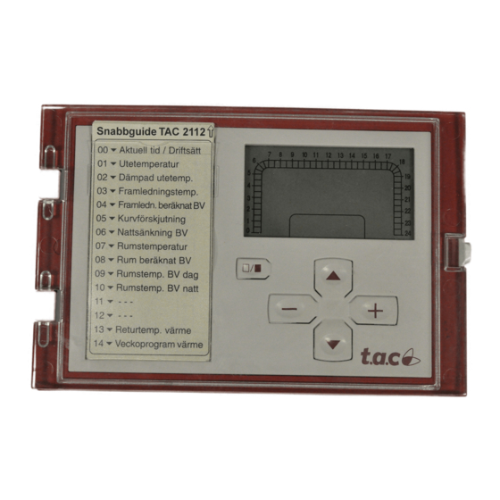
TAC 2112, Manual Installation 5.3 Starting up Before the power is switched on The following should be carried out before switching on the power: Check that sensors and actuators are connected correctly. Set the changeover switch to configuration. It is possible to gain access to the changeover switch by pulling out the quick reference and removing the plastic disk in front of it. -
Page 30
TAC 2112, Manual Installation Close input X1 (forced night setback) to measurement neutral (M) and check that the clock and the flashing moon appear in the display window. Close input U3 (pump alarm) to measurement neutral (M) and check that the alarm symbol ! appears in the display window. -
Page 31: Troubleshooting
TAC 2112, Manual Troubleshooting Troubleshooting The TAC 2112 is usually a very reliable controller. If problems occur in spite of this, you can use the troubleshooting advice given below. If you require further assistance, please contact your nearest TAC service point.
-
Page 32
TAC 2112, Manual Troubleshooting Problem Check (that) … • The calculated setpoint does the effect from the remote heating not seem to be correct control (SPC, P 80) is reasonable • The pump is not running if the pump has stopped due to a… -
Page 33: Functional Description
TAC 2112, Manual Functional Description 7 Functional Description Introduction This chapter contains a description of all the functions in the controller. At the end of each section is a list of parameters. How to read off and set these parameters is described in Chapter 3, “Using the operator’s panel”.
-
Page 34
TAC 2112, Manual Functional Description Forced night setback When the controller is in the “timed operation” operating mode and the input X2 is connected to M (measurement neutral), the following takes place: • The symbols on the left are displayed in the display window (the moon flashes). -
Page 35
TAC 2112, Manual Functional Description Manual control When the controller is in the “manual control” operating mode, the following takes place: • The symbol on the left is displayed in the display window. • All relay outputs except for Open heating valve and Close heating valve are activated (the contacts are closed). -
Page 36: Heat Control
TAC 2112, Manual Functional Description Heat control 7.3.1 Functional diagram The TAC 2112 can control heat with or without a reference sensor. The control function both with and without a reference sensor is described in the illustrations below. Time program…
-
Page 37: Damped Outdoor Temperature
TAC 2112, Manual Functional Description 7.3.2 Damped outdoor temperature The object of controlling the supply temperature is to maintain the correct room temperature irrespective of the outdoor temperature. The heat storage capacity of the building shell means that a change in the outdoor temperature affects the room temperature only after a certain time.
-
Page 38: Reset Curve For Outdoor Compensation
TAC 2112, Manual Functional Description 7.3.3 Reset curve for outdoor compensation The correct amount of heating is supplied to the building throughout the year by allowing the supply temperature to be changed as a function of the damped outdoor temperature. This function is described by the reset curve.
-
Page 39: Automatic Adjustment Of The Reset Curve
TAC 2112, Manual Functional Description 7.3.4 Automatic adjustment of the reset curve In systems with reference sensors, the controller can adjust the reset curve automatically. The temperature at the reference sensor is used to continually carry out small corrections (±1 C) to the three points °…
-
Page 40: Supply Controller
TAC 2112, Manual Functional Description Criteria for automatic curve adjustment The following criteria must be met for the automatic curve adjustment to work: • A reference sensor is installed. • Automatic curve adjustment is on (P 27). • The controller is working under timed operation.
-
Page 41: Room Controller
TAC 2112, Manual Functional Description The following data apply for the supply controller: P band: 10–200 ° I time: 2 minutes Dead zone: ° The supply setpoint is set to Min. supply temperature (P 22) when the pump is stopped in order to ensure that the valve moves into the closed position.
-
Page 42: Return Temperature Limitation
TAC 2112, Manual Functional Description Parameters P No. Parameter Min. Max. Step Default Comments P 07 Room temperature 0 °C 45 °C 0,1 °C With reference sensor only P 08 Calculated SP, room temp. –35 °C 70 °C 0,1 °C…
-
Page 43: Remote Heating Control (Spc)
TAC 2112, Manual Functional Description Parameters P No. Parameter Min. Max. Step Default Comments P 13 Return temperature, heating 0 °C 120 °C 0,3 °C Step=0,1 at 2–55 °C P 43 Return limitation on/off 0 (off) 1=heating, 2=heat.+dom.h.w. P 44 Return limit., heating, P band 10 °C…
-
Page 44: 7.3.9 Pump Control
TAC 2112, Manual Functional Description 7.3.9 Pump control The pump control acts to utilise the heat accumulated in the building as efficiently as possible by allowing the circulation pump to operate only when there is a specific heating requirement. Pump stop The circulation pump is stopped and the setpoint for the supply temperature is set to Min.
-
Page 45: Variable Night Setback
TAC 2112, Manual Functional Description 7.3.10 Variable night setback To ensure that the heating installation is able to reset the room temperature after a night setback in the event of a low outdoor temperature, the controller uses what is known as variable night setback.
-
Page 46
TAC 2112, Manual Functional Description Without reference sensor Without a reference sensor, the heating time varies with the damped outdoor temperature according to the curve below. Heating time (minutes) P 37 P 38 P 39 Damped 10 15 20 Curve for morning heating… -
Page 47
TAC 2112, Manual Functional Description Example Setpoint room=21 ° Room temperature=18 ° Damped outdoor temperature=10 ° The above results in a deviation of (18–21) C=–3 C. The ° ° y-value of the curve at +10 C is 20 minutes, which gives a °… -
Page 48: Reduced Daytime Operation (Optimised Stop)
TAC 2112, Manual Functional Description 7.3.12 Reduced daytime operation (optimised stop) In systems with a reference sensor, the controller can determine whether a transition to night operation can take place earlier than the time set. The controller calculates a new transition time on the basis of the deviation in room temperature.
-
Page 49: Extended Daytime Operation
TAC 2112, Manual Functional Description 7.3.13 Extended daytime operation Daytime operation can be extended by means of an integral timer. This timer is started from outside, e.g. from an external pressure changeover switch which momentarily connects input X1 to M (measurement neutral).
-
Page 50: Clock
TAC 2112, Manual Functional Description Clock The controller contains a calendar clock with automatic transition between daylight saving time and normal time and automatic compensation for leap years. The clock must be set manually after a power cut lasting more than 48 hours.
-
Page 51: Time Schedules
TAC 2112, Manual Functional Description Time schedules The TAC 2112 includes two weekly programs and a yearly program (holiday program). Weekly program 1 is used to reduce the room temperature during night operation. Weekly program 2 is used to control external units (via output K4).
-
Page 52: Memory Backup
TAC 2112, Manual Functional Description Circulation pump The alarm is triggered immediately when the input for the pump alarm is activated (U3). Parameters P No. Parameter Min. Max. Step Default Comments P 82 Alarm, pump 0=no alarm, 1=alarm P 83 Alarm, supply temp.
-
Page 53: Manual Control
It is possible to step through a sequence comprising the following steps by pressing either • (P 99) Display program version • (P 99) Display type designation (2112) • (P 99) Testing of the display window: turns all the symbols in the display window on, turns all the symbols off •…
-
Page 54
TAC 2112, Manual Functional Description Parameters P No. Parameter Min. Max. Step Default Comments P 95 Serial number (part 1) 0000 9999 * as per type label P 96 Serial number (part 2) 0000 9999 * as per type label P 99 Display test, etc. -
Page 55: Technical Data
TAC 2112, Manual Technical data Technical data Thermistor inputs Thermistor type…………1800 Ω/25 °C Meas. range: water temperature……0 °C – +120 °C room temperature ……0 °C – +45 °C outdoor temperature ….. –30 °C – +45 °C Accuracy –50 °C – +2 °C ……….0,3 °C +2 °C –…
-
Page 56
TAC 2112, Manual Technical data Calendar clock Accuracy ……….±12 minutes/year at +25 ° Reserve run time ……. 48 hours (no battery required) Power supply Operating voltage ……..24 V AC ±20%, 50–60 Hz Power consumption…………..3W Electromagnetic compatibility Emission……………..EN 50081-1 Immunity …………….EN 50082-1… -
Page 57: Appendix A, Commissioning Protocol/List Of Parameters
Appendix A, Commissioning Protocol / List of Parameters This protocol is to be used when commissioning the TAC 2112 controller. Note your settings in the column marked “Change”. How to read off and set parameters is described in Chapter 3, “Using the operator’s panel”.
-
Page 58
TAC 2112, Manual Commissioning Protocol / List of Parameters P No. Parameter Min. Max. Step Default Change Comments Press at the same time to get to P 00 or P 15 P 15 Set time 00:00 23:59 00:01 00:00 hour:minute… -
Page 59
TAC 2112, Manual Commissioning Protocol / List of Parameters P No. Parameter Min. Max. Step Default Change Comments P 37 Max heating time 24 h h=hours. See curve. P 38 Heating time, –10 °C (y0) 0 m. 1440 m. 1 m. -
Page 60
TAC 2112, Manual Commissioning Protocol / List of Parameters P No. Parameter Min. Max. Step Default Change Comments P 50 P 51 P 52 P 53 P 54 P 55 P 56 P 57 P 58 P 59 P 60… -
Page 61
TAC 2112, Manual Commissioning Protocol / List of Parameters P No. Parameter Min. Max. Step Default Change Comments P 74 Supply temp. pump stop 0°C 120°C 1°C 20°C P 75 Exercise on/off 0 (off) 1 (on) 1 (on) 0=off, 1=on P 76 Min. -
Page 62
TAC 2112, Manual Commissioning Protocol / List of Parameters A:6 (6), 0-004-7459-3 (GB) 1999-08-01, TAC AB… -
Page 63: Index
TAC 2112, Manual Index Index alarm damped outdoor temperature description 7:19 description 7:4 indication 3:5 reading off 4:1 reading off 4:5 daylight saving time 7:18 resetting 4:5 day-to-day usage 4:1 supply temperature 7:19 demands on environment 8:2 ambient temperature 8:2…
-
Page 64
TAC 2112, Manual Index outputs leap years 7:18 indication 3:5 K2 7:13 K3 7:19 K4 7:19 M rail 5:7 manual control 7:21 manual control technical data 8:1 description 7:21 testing 5:9 indication 3:3 operating cycle 7:3 setting operating cycle 4:5 memory backup 7:20 P No. -
Page 65
TAC 2112 Manual Index timer daylight saving time 7:18 sliding night setback 7:13 description 7:18 SPC 7:11 leap years 7:18 start time optimisation see morning heating setting 4:6 starting up 5:9 technical data 8:2 stop time optimisation 7:16 timer program… -
Page 66
TAC 2112, Manual Index Index: 4(4), 0-004-7459-3 (GB) TAC AB, 1999-08-01… -
Page 67
Or e-mail to: TAC AB helpdesk@tac.se Helpdesk Jägershillgatan 18 SE-213 75 MALMÖ SWEDEN —————————————————————————————————————————— I have found the following errors and/or unclear descriptions in “TAC 2112” (Art.number 0-004-7459-3 (GB)): On page:……………………………………………………………………………………On page:……………………………………………………………………………………On page:………………………………………………………. -
Page 68
TAC 2112, Manual Reply form 1999-08-01, TAC AB… -
Page 70
TAC AB, Jägershillgatan 18, SE-213 75 MALMÖ, SWEDEN, +46 40 38 68 50, www.tac.se…
-
52, TAC 2112, Manual Functional Description 7:20 (22), 0-004-7459-3 (GB) 1999-08-01, TAC AB Circulation pump The alarm is triggered immediately when the input for the pump alarm is activated (U3). Parameters P No. Parameter Min. Max. Step Default Comments P 82 Alarm, pump 0 1 1 — 0=no alarm, 1=alarm P 83 Alarm, supply temp. 0 1 1 — 0=no alarm, 1=alarm 7.7 Memory bac…
-
33, TAC 2112, Manual Functional Description TAC AB, 1999-08-01 0-004-7459-3 (GB), 7:1( 22 ) 7 Functional Description 7.1 Introduction This chapter contains a description of all the functions in the controller. At the end of each section is a list of parameters. How to read off and set these parameters is described in Chapter 3, “Using the operato…
-
59, TAC 2112, Manual Commissioning Protocol / List of Parameters TAC AB, 1999-08-01 0-004-7459-3 (GB), A:3(6) P No. Parameter Min. Max. Step Default Change Comments P 37 Max heating time 0 h 24 h 1 h 6 h h=hours. See curve. P 38 Heating time, –10 °C (y0) 0 m. 1440 m. 1 m. 120 m. Changed by ctrl. if P 35=1 P 39 Heating time, +10 °C (y1) 0…
-
24, TAC 2112 TAC 2112, Manual Installation 5:4( 10 ), 0-004-7459-3 (GB) 1999-08-01, TAC AB Procedure for mounting controller on a wall: 1. Drill holes for the three screws as shown in the scale drawing below. 30 30 65 37 13 3 5 2. Remove the backplate from the electronic part (see above). 3. Mount the backplate and the metal brace. 4. Connect the wires. 5. Push the el…
-
49, TAC 2112 TAC 2112, Manual Functional Description TAC AB, 1999-08-01 0-004-7459-3 (GB), 7:17( 22 ) 7.3.13 Extended daytime operation Daytime operation can be extended by means of an integral timer. This timer is started from outside, e.g. from an external pressure changeover switch which momentarily connects input X1 to M (measurement neutral). The time for extended daytime opera…
-
5, TAC 2112, Manual About this manual TAC AB, 1999-08-01 0-004-7459-3 (GB) 1:1(2) 1 About this manual 1.1 Overview Chapter 2, TAC 2112 heating controller This gives a brief introduction to the controller. Chapter 3, Using the operator’s panel This provides a more detailed explanation of how to read off and set the values using the buttons and the display window. Chapter 4, …
-
37, TAC 2112, Manual Functional Description TAC AB, 1999-08-01 0-004-7459-3 (GB), 7:5( 22 ) 7.3.2 Damped outdoor temperature The object of controlling the supply temperature is to maintain the correct room temperature irrespective of the outdoor temperature. The heat storage capacity of the building shell means that a change in the outdoor temperature affe…
-
60, TAC 2112 TAC 2112, Manual Commissioning Protocol / List of Parameters A:4 (6), 0-004-7459-3 (GB) 1999-08-01, TAC AB P No. Parameter Min. Max. Step Default Change Comments P 50 �…
-
14, TAC 2112, Manual Using the Operator´s Panel 3:6(6), 0-004-7459-3 (GB) 1999-08-01, TAC AB 3.3 How are the buttons used? The controller has five buttons beneath the display window. Select parameter weekly program Increase/decrease parameter value Da y time / ni g ht operation The buttons on the operator’s panel The and buttons are used to select a parameter. …
-
32, TAC 2112, Manual Troubleshooting 6:2( 2 ), 0-004-7459-3 (GB) 1999-08-01, TAC AB Problem Check (that) … The calculated setpoint does not seem to be correct • the effect from the remote heating control (SPC, P 80) is reasonable The pump is not running • if the pump has stopped due to a high outdoor temperature or a low supply temperatu…
-
22, TAC 2112 TAC 2112, Manual Installation 5:2( 10 ), 0-004-7459-3 (GB) 1999-08-01, TAC AB Procedure for removing the backplate: 1. Remove the metal brace by unscrewing the fastening device. 2. Press in the two round “buttons” on the sides of the controller. 3. Hold the “buttons” in while carefully pulling the electronic part out of the back. Fastening device …
Table of Contents for TAC 2112:
-
TAC 2112, Manual Technical data 2:2(2), 0-004-7459-3 (GB) 1999-08-01, TAC AB Calendar clock Accuracy ………………………………………..±12 minutes/year at +25 ° C Reserve run time ………………………….48 hours (no battery required) Power supply Operating voltage…………………………….. 24 V AC ±20%, 50–60 Hz Power consumption…………………………………………………………… 3W Electromagnetic compatibility Emission………………………..
-
TAC 2112, Manual Functional Description TAC AB, 1999-08-01 0-004-7459-3 (GB), 7:13( 22 ) 7.3.10 Variable night setback To ensure that the heating installation is able to reset the room temperature after a night setback in the event of a low outdoor temperature, the controller uses what is known as variable night setback. This means that the magnitude of the setback is a function of the damped outdoor temperature according to the curve below. 0% 100% -10 0 5-5 10 15 20-
-
TAC 2112, Manual Functional Description TAC AB, 1999-08-01 0-004-7459-3 (GB), 7:15( 22 ) Example Setpoint room=21 ° C Room temperature=18 ° C Damped outdoor temperature=10 ° C The above results in a deviation of (18–21) ° C=–3 ° C. The y-value of the curve at +10 ° C is 20 minutes, which gives a heating time of 60 minutes (3 × 20). The curve points are automatically adjusted after each morning heating, provided that the parameter Adaptive start time optimisation (P 35) is set to “on�
-
TAC 2112, Manual Installation TAC AB, 1999-08-01 0-004-7459-3 (GB), 5:3(10) Procedure for mounting controller in a panel: 1. Make an opening in the panel as shown in the adjacent scale drawing. The max. panel thickness is 5 mm. �
-
TAC 2112, Manual Index TAC AB, 1999-08-01 0-004-7459-3 (GB), Index:1(4) Index A alarm description 7:19 indication 3:5 reading off 4:5 resetting 4:5 supply temperature 7:19 ambient temperature 8:2 assembly outdoor sensor 5:5 reference sensor 5:5 regulator 5:1 return sensor 5:5 setting devices see instructions for each setting device supply sensor 5:5 automatic adjustment of control curve 7:6 C cable entries 5:7 cable lengths 5:8
-
TAC 2112, Manual Commissioning Protocol / List of Parameters A:6 (6), 0-004-7459-3 (GB) 1999-08-01, TAC AB
-
TAC 2112, Manual Day-to-day Usage TAC AB, 1999-08-01 0-004-7459-3, 4:5(6) 4.6 Reading alarms When an alarm has been triggered, the ! symbol in the display window will flash. The display window will also specify what has triggered the alarm. Procedure for reading off alarms: 1 2 3 4 5 6 7 8 9 10 11 12 13 14 15 16 17 18 0 23 22 21 20 19 24 K1 P 82 1 ! 1 Select parameter number (P No.) by pressing or as shown in the list below. The parameter number is increased and de
-
TAC 2112, Manual Day-to-day Usage TAC AB, 1999-08-01 0-004-7459-3, 4:3(6) 4.5 Setting the time schedule for daytime/night operation 4.5.1 Weekly program for night setback of heat When the controller is supplied, it is set for night setback of heat between 22:00 and 06:00 for all days of the week. See chapter 7 for a more detailed description of the time schedule. Procedure for changing the weekly program: 1 2 3 4 5 6 7 8 9 10 11 12 13 14 15 16 17 18 0 23 22 21 20 19 24 K1 MO P 14 1 Select parameter numbe
-
TAC 2112, Manual Reply form TAC AB, 1999-08-01 You can help make this manual even better! We need your help to produce user-friendly documentation and would appreciate it of you would make a note of any errors in this manual or of any suggested improvements. Send to: TAC AB Helpdesk Jägershillgatan 18 SE-213 75 MALMÖ SWEDEN Or e-mail to: [email protected] ——————————————————————-
-
TAC 2112, Manual Installation TAC AB, 1999-08-01 0-004-7459-3 (GB), 5:5(10) Outdoor temperature sensor, EGU Mount the sensor to an exterior wall facing north or north-west. Place it approximately 3 m above ground with the cable entry facing down. If several TAC 2000 are to be used in the same building, it may be sufficient to mount only one outdoor temp
-
TAC 2112, Manual Day-to-day Usage 4:4(6), 0-004-7459-3 (GB) 1999-08-01, TAC AB 1 2 3 4 5 6 7 8 9 10 11 12 13 14 15 16 17 18 0 23 22 21 20 19 24 K1 P 65 01.01 5 Go to P 65 by pressing . 6 Set the end date (month.day) by pressing or . 7 Exit by pressing . Procedure for deleting a holiday period: 1 2 3 4 5 6 7 8 9 10 11 12 13 14 15 16 17 18 0 23 22 21 20 19 24 K1 P 63 1 1 Select parameter number P 63 by pressing or . The parameter number is increased and decreased by p
-
TAC 2112, Manual Reply form 1999-08-01, TAC AB
-
TAC 2112, Manual Functional Description 7:6 (22), 0-004-7459-3 (GB) 1999-08-01, TAC AB 7.3.3 Reset curve for outdoor compensation The correct amount of heating is supplied to the building throughout the year by allowing the supply temperature to be changed as a function of the damped outdoor temperature. This function is described by the reset curve . The reset curve is made of three adjustable curve points. The outer points are firmly defined by the outdoor
-
TAC 2112, Manual Commissioning Protocol / List of Parameters A:4 (6), 0-004-7459-3 (GB) 1999-08-01, TAC AB P No. Parameter Min. Max. Step Default Change Comments P 50
Questions, Opinions and Exploitation Impressions:
You can ask a question, express your opinion or share our experience of TAC 2112 device using right now.
1 TAC 2112 Manual T1 P (GB),
2
3 Contents TAC 2112 Manual Subject to modification TAC AB Contents 1 About this manual… 1:1 1.1 Overview… 1:1 1.2 How to use this manual… 1:1 1.3 Associated documentation… 1:2 2 TAC 2112 heating controller… 2:1 3 Using the operator s panel… 3:1 3.1 Introduction… 3:1 3.2 What is shown in the display window?… 3: Parameter numbers and parameter values… 3: Operating modes… 3: Weekly program… 3: Outputs from the controller… 3: Alarm… 3:5 3.3 How are the buttons used?… 3:6 4 Day-to-day usage… 4:1 4.1 Introduction… 4:1 4.2 Reading temperatures… 4:1 4.3 Setting temperatures… 4:2 4.4 Adjusting the reset curve… 4:2 4.5 Setting the time schedule for daytime/night operation… 4: Weekly program for night setback of heat… 4: Reduction in heating during a holiday period… 4: Weekly program for external units… 4:4 4.6 Reading alarms… 4:5 4.7 Setting the operating mode… 4:5 4.8 Setting the clock… 4:6 5 Installation… 5:1 5.1 Assembly… 5:1 5.2 Connection… 5:6 5.3 Starting up… 5:10 6 Troubleshooting… 6:1 TAC AB, (GB), i
4 Contents 7 Functional description… 7:1 7.1 Introduction… 7:1 7.2 Controller operating modes… 7:1 7.3 Heat control… 7: Functional diagram… 7: Damped outdoor temperature… 7: Reset curve for outdoor compensation… 7: Automatic adjustment of the reset curve… 7: Supply controller… 7: Room controller…7: Return temperature limitation… 7: Remote heating control (SPC)… 7: Pump control… 7: Variable night setback… 7: Morning heating… 7: Reduced daytime operation (optimised stop)… 7: Extended daytime operation… 7: Forced night setback… 7: Clock… 7: Time schedules… 7: Alarm… 7: Memory backup… 7: Adjustment of sensor inputs… 7: Manual control… 7: Test functions… 7:21 8 Technical data… 8:1 Appendix A, Commissioning protocol/list of parameters… A:1 Index… Index:1 ii, (GB) TAC AB,
5 About this manual 1 About this manual 1.1 Overview Chapter 2, TAC 2112 heating controller Chapter 3, Using the operator s panel Chapter 4, Day-to-day usage Chapter 5, Installation Chapter 6, Troubleshooting Chapter 7, Functional description Chapter 8, Technical data This gives a brief introduction to the controller. This provides a more detailed explanation of how to read off and set the values using the buttons and the display window. This chapter provides you with sufficient information to be able to use the controller during normal operation. This chapter shows you how to assemble, connect and commission the controller. This chapter contains actions that you yourself can implement in order to locate and rectify any faults in the control system. Here you will find a detailed description of all the functions and parameters of the controller. All the technical data for the TAC 2112 can be found here. Appendix A, Commissioning protocol/list of parameters Index Here you will find a commissioning protocol, which also provides support for adjustment of the controller. All the parameters in the controller are also defined. At the end of this manual is an index with page references. TAC AB, (GB) 1:1(2)
6 About this manual 1.2 How to use this manual During normal operation During installation and commissioning During troubleshooting The TAC 2112 Manual describes all the functions and procedures necessary to install, adjust and use the controller. The TAC controller, as well as other products from the 2000-range, should not be used for purposes other than intended for. Before reading off or setting temperatures and other parameters during normal operation, it is sufficient to read Chapter 3, Using the operator s panel and Chapter 4, Day-to-day usage. You can also use the Quick Reference on the front of the controller. Before installing and commissioning the controller, you should read Chapter 5, Installation. The enclosed document entitled Installation instructions may also be used. A commissioning protocol is supplied with the controller, but this can also be found in Appendix A. In the event of a fault with the controller you should read Chapter 3, Using the operator s panel, Chapter 4, Day-to-day usage, and Chapter 6, Troubleshooting. 1.3 Associated documentation Enclosed documentation The documentation listed below is supplied with the controller. It contains all the information you need to install and commission the controller. Installation instructions for the TAC 2112 (part number 0FL-3678) Commissioning protocol for the TAC 2112 (part number 0FL-3679) TAC 2112 Quick Reference (part number 0FL-3672) 1:2(2), (GB) , TAC AB
7 TAC 2112 Heating Controller 2 TAC 2112 Heating Controller The TAC 2112 is a digital heating controller for controlling waterborne heat in buildings. The radiator circuit is controlled according to an outdoor temperaturecompensated reset curve, with or without a reference sensor. The controller contains a real time clock and can be set for weekly and yearly time schedules, along with powerful functions for optimum energy saving. It is very simple to read and set temperatures and other parameters. The display window provides clear information with digits and symbols. The controller can be mounted on a norm rail, in a panel or on a wall. TAC AB, (GB), 2:1(2)
8 TAC 2112 Heating Controller The TAC 2112 is designed to control heat in apartment buildings, offices, schools and other large buildings. Installation with district heating The controller operates both with and without reference sensors. However, some optimisation functions require a reference sensor to be installed. Installation with heating boiler 2:2(2), (GB) , TAC AB
9 Using the Operator s Panel 3 Using the Operator s Panel 3.1 Introduction This chapter shows you how to use the buttons on the operator s panel and the display window to read off and set parameters such as temperatures. 3.2 What is shown in the display window? The display window provides you with information from the heating installation in the form of digits and symbols. 24-hour time bar Parameter number Parameter value Alarm Pump MO TU WE TH FR SA P 00 12:00! K1 K2 SU AM C F K3 K Heating valve opens Heating valve closes Morning heating Heating off Fixed night setback Timed operation Fixed daytime operation Buzzer alarm Manual control Weekly program 2 Information in the display window TAC AB, (GB), 3:1(6)
10 Using the Operator s Panel Parameter numbers and parameter values The controller has a list of 100 parameters numbered from 0 to 99. Some of these parameters can be set (such as the setpoint for supply temperature), while others can just be read (such as the outdoor temperature). Some parameters cannot be displayed if the corresponding function is blocked. For example, the room temperature will not be displayed if there is no reference sensor. The parameter numbers and parameter values in the display window constitute a window to the list of parameters. List of parameters P 18 Reset curve (x1) P 19 Reset curve (y0) Display window 6 P 20 Reset curve (y1) Window up Parameter number Parameter value K1 MO P C P 24 P band, supply c. P 25 Run time, actuator P 26 Max. increase rate Window down The display window constitutes a window to the list of parameters The buttons and are used to move the window up and down over the list of parameters. 3:2(6), (GB) , TAC AB
11 Using the Operator s Panel Operating modes The different operating modes of the controller are shown in the display window using the symbols below MO TU WE TH FR SA P 00 12:00! K1 K2 SU AM C F K3 K Operating mode The symbols for the operating mode of the controller The symbols have the following meanings: Heating off Fixed night setback Timed operation Fixed daytime operation Manual control Heat reduction during holiday period Forced night setback from external connection (flashing moon) Extended daytime operation from external connection (flashing sun) How to set the operating mode is described in chapter 4. See chapter 7 for a more detailed description of the operating modes. TAC AB, (GB), 3:3(6)
12 Using the Operator s Panel Weekly program The weekly program for daytime and night operation is displayed in the form of a 24-hour time bar from 00:00 to 24:00. Filled segments show the time of day when daytime operation is to be effected. 24-hour time bar Weekdays MO TU WE TH FR SA P 00 12:00! K1 K2 SU AM C F K3 K The symbols for weekly programs Each segment on the 24-hour bar equals 30 minutes. A filled-in segment signifies daytime operation. Segments which are not filled in signify night setback. The days of the week are included beneath the clock. They show the day of the week to which the 24-hour bar refers. MO = Monday TU = Tuesday WE = Wednesday TH = Thursday FR = Friday SA = Saturday SU = Sunday How to set the weekly program is described on in chapter 4. See chapter 7 for a more detailed description of time schedules. 3:4(6), (GB) , TAC AB
13 Using the Operator s Panel Outputs from the controller The controller has a number of outputs for the control of external units (such as the actuator for the heating valve). When an output is activated, its symbol is displayed in the display window Pump MO TU WE TH FR SA P 00 12:00! K1 K2 Morning heating Heating valve opens Buzzer alarm SU AM C F K3 K Weekly program 2 Heating valve closes The symbols for outputs from the controller Alarm In the event of an alarm, a flashing alarm symbol is displayed in the display window MO TU WE TH FR SA P 00 12:00! K1 K2 SU AM C F K3 K Alarm The alarm symbol How to read off alarms is described in chapter 4. See chapter 7 for a more detailed description of the alarm function in the controller. TAC AB, (GB), 3:5(6)
14 Using the Operator s Panel 3.3 How are the buttons used? The controller has five buttons beneath the display window. Daytime/night operation weekly program Select parameter Increase/decrease parameter value The buttons on the operator s panel The and buttons are used to select a parameter. The and buttons are used to change a parameter value. The button is used to toggle between a filled and a blank segment in the 24-hour clock. To save a changed parameter value, press again. 3:6(6), (GB) , TAC AB
15 Day-to-day Usage 4 Day-to-day Usage 4.1 Introduction 4.2 Reading temperatures This chapter provides sufficient information for you to read off and set temperatures and other parameters during normal operation. All parameters and functions are described in detail in Chapter 7, Functional description. Procedure for reading a temperature: P C Select parameter number (P No.) by pressing or as shown in the list below. Increase or decrease the number by pressing or K Hold down the button for fast increase/decrease. 3 Press and at the same time to get to P 15 P Read the value. Temperature P No. Outdoor temperature P 01 Damped outdoor temperature P 02 Supply temperature P 03 Supply temperature, calculated setpoint P 04 Room temperature P 07 Room temperature, calculated setpoint P 08 Return temperature, heating circuit P 13 TAC AB, , 4:1(6)
16 Day-to-day Usage 4.3 Setting temperatures Procedure for setting a temperature: K1 P C Select parameter number (P No.) by pressing or as shown in the list below. The parameter number is increased and decreased by pressing or. Hold down the button for fast increase/decrease. 2 Press and at the same time to get to P 15 P Change the temperature by pressing or. 4 Exit by pressing. Temperature P No. Night setback of supply temperature P 06 Room temperature, setpoint day P 09 Room temperature, setpoint night P Adjusting the reset curve Procedure for adjusting the reset curve: K1 P C Select parameter number (P No.) by pressing or as shown in the figure below. Increase and decrease by pressing or. Hold down the button for fast increase/decrease. 2 Press and at the same time to get to P 15 P Adjust the curve point by pressing or. 4 Exit by pressing. P 23 P P 19 P 20 P 18 Parallel shift ± C P 21 P Damped Reset curve parameters See chapter 7 for a more detailed description of the function of the reset curve. 4:2(6), (GB) , TAC AB
17 Day-to-day Usage 4.5 Setting the time schedule for daytime/night operation Weekly program for night setback of heat When the controller is supplied, it is set for night setback of heat between 22:00 and 06:00 for all days of the week. See chapter 7 for a more detailed description of the time schedule. Procedure for changing the weekly program: MO P 14 K Select parameter number P 14 by pressing or. The parameter number is increased and decreased by pressing. 2 When the parameter number has been selected, the 24-hour time bar will be displayed showing MO for Monday. or 3 Scroll in the 24-hour time bar by pressing or until you get to the segment to be changed. The segment will flash. 4 Change the half-hour segments by pressing. A filled-in segment will result in daytime operation. When a segment has been changed, the next segment will start to flash. 5 Scroll on to TU for Tuesday by pressing. 6 Change the half-hour segments for Tuesday by pressing. 7 Repeat steps 5 and 6 for each day of the week. 8 Exit by pressing or Reduction in heating during a holiday period It is possible to program up to six holiday periods. During a holiday period, the heating is controlled at the setpoint for the night. No holiday periods are programmed prior to delivery. See chapter 7 for a more detailed description of time schedules. Procedure for setting a holiday period: K1 P Select parameter number P 63 by pressing or. The parameter number is increased and decreased by pressing. Press and at the same time to get to P 15 P Select a holiday period (1 6) by pressing or. or K1 P Go to P 64 by pressing. 4 Set the start date (month.day) by pressing or. Hold the button down for fast increase/decrease. TAC AB, , 4:3(6)
18 Day-to-day Usage K1 P Go to P 65 by pressing. 6 Set the end date (month.day) by pressing or. 7 Exit by pressing. Procedure for deleting a holiday period: K1 P Select parameter number P 63 by pressing or. The parameter number is increased and decreased by pressing or. Press and at the same time to get to P 15 P Select a holiday period (1 6) by pressing or K1 P Go to P 64 by pressing. 4 Change the start date to day 0 in the month (month.00) by pressing or. Hold the button down for fast increase/decrease. 5 Exit by pressing. It is also possible to change the end date to day 0 to delete a holiday period Weekly program for external units This weekly program can be used to control an external unit (such as lighting). The controller is set for night operation on all days of the week when it is delivered. See chapter 7 for a more detailed description of time schedules. Procedure for changing the weekly program: MO P 61 K Select parameter number P 61 by pressing or. The parameter number is increased and decreased by pressing. Press and at the same time to get to P 15 P When the parameter number has been selected, the 24-hour clock will be displayed showing MO for Monday. or 3 Scroll in the 24-hour time bar by pressing or until you get to the segment to be changed. The segment will flash. 4 Change the half-hour segments by pressing. A filled-in segment will result in daytime operation. When a segment has been changed, the next segment will start to flash. 5 Scroll on to TU for Tuesday by pressing. 6 Change the half-hour segments for Tuesday by pressing. 7 Repeat steps 5 and 6 for each day of the week. 8 Exit by pressing or. 4:4(6), (GB) , TAC AB
19 Day-to-day Usage 4.6 Reading alarms When an alarm has been triggered, the! symbol in the display window will flash. The display window will also specify what has triggered the alarm. Procedure for reading off alarms: P 82 1! K Select parameter number (P No.) by pressing or as shown in the list below. The parameter number is increased and decreased by pressing or. 2 Press and at the same time to get to P 15 P Hold down the button for fast increase/decrease. 4 Read the value. 1=ALARM, 0=NO ALARM The alarm is reset automatically when the reason for it no longer exists. Temperature P No. Circulation pump P 82 Supply temperature P Setting the operating mode The controller usually operates in a timed manner; that is to say, a weekly program and yearly program determine whether the supply temperature or room temperature should be controlled to a daytime or night setpoint. The controller can also be set to other operating modes. See chapter 7 for a more detailed description of the operating modes. Procedure for setting an operating mode: TU P 00 12:35 K Select parameter number P 00 by pressing or. The parameter number is increased and decreased by pressing. 2 Change the operating mode by pressing or. 3 Confirm by pressing. or Operating mode Symbol Heating off Fixed night setback Timed operation Fixed daytime operation Manual control TAC AB, , 4:5(6)
20 Day-to-day Usage 4.8 Setting the clock To display the current time on the clock, select parameter P 00 (usually displayed). The clock must be set after a power cut lasting more than 48 hours. See chapter 7 for a more detailed description of the clock. Procedure for setting the time: K1 P 15 0: Select parameter number P 15 by pressing or. The parameter number is increased and decreased by pressing or. Press and at the same time to get to P 15 P Change the clock by pressing or. Hold down the button for fast increase/decrease. 3 Exit by pressing. Procedure for setting the date: K1 P Select parameter number P 16 by pressing or. The parameter number is increased and decreased by pressing or. Press and at the same time to get to P 15 P Change the date (month.day) by pressing or. Hold down the button for fast increase/decrease. 3 Exit by pressing K1 P Procedure for setting the year: 1 Select parameter number P 17 by pressing or. The parameter number is increased and decreased by pressing. Press and at the same time to get to P 15 P Change the year by pressing or. 3 Exit by pressing. Days of the week are calculated automatically by the controller and do not, therefore, need to be set. or 4:6(6), (GB) , TAC AB
21 Installation 5 Installation 5.1 Assembly Controller Position the controller so that it is easy to read off and set values and so that the cover can be opened. The permissible ambient temperature range and humidity range must not be exceeded (see Technical data, chapter 8). The controller is enclosed in a plastic box comprising four parts: Transparent cover Electronic part Backplate with terminal block Metal Brace The backplate must be removed from the electronic part in order to gain access to the terminal blocks. There is a modular jack on the electronic part for connecting the information tool Inta2000.! WARNING! Check that the terminal blocks are not connected to the mains before removing the backplate. TAC AB, (GB), 5:1(10)
22 Installation Procedure for removing the backplate: 1. Remove the metal brace by unscrewing the fastening device. 2. Press in the two round buttons on the sides of the controller. 3. Hold the buttons in while carefully pulling the electronic part out of the back. Fastening device The controller can be mounted in three different ways: On a norm rail EN (TS 35 mm) In a panel, with or without a backplate Directly on a wall Procedure for mounting controller on a norm rail: 1. Place the backplate of the controller with the metal brace on the upper side of the rail (arrow 1). 2. Turn it downwards until it snaps onto the rail (arrow 2). 3. Press on the electronic part. Secure the controller into the metal brace with the fastening device for panel mounting. 4. To remove, place a screwdriver in the lock on the bottom of the controller and pull down. It is then possible to lift the controller diagonally upwards and off the rail. 5:2(10), (GB) , TAC AB
23 Installation Procedure for mounting controller in a panel: 1. Make an opening in the panel as shown in the adjacent scale drawing. The max. panel thickness is 5 mm , Remove the backplate from the electronic part (see above). Remove the terminal blocks from the backplate. 3. Place the controller in the panel and lock it in position by tightening the two locking screws. Seal the holes using the two gaskets. It is not necessary to install the metal brace when mounting panel. 4. Attach the terminal blocks to the pin on the back of the controller. Note that the terminal blocks are coded, so they cannot be interchanged. It is also possible to use the backplate when fitting the controller in a panel. TAC AB, (GB), 5:3(10)
24 Installation Procedure for mounting controller on a wall: 1. Drill holes for the three screws as shown in the scale drawing below Remove the backplate from the electronic part (see above). 3. Mount the backplate and the metal brace. 4. Connect the wires. 5. Push the electronic part onto the backplate and secure the controller in the metal brace with the fastening device max. 5 Dimensions in mm. 5:4(10), (GB) , TAC AB
25 Installation Outdoor temperature sensor, EGU Supply temperature sensor, EGWS, EGA Room temperature sensor, EGRL Return temperature sensor, EGWS, EGA Actuators M5, M15, M42, M44, M500, M750 Mount the sensor to an exterior wall facing north or north-west. Place it approximately 3 m above ground with the cable entry facing down. If several TAC 2000 are to be used in the same building, it may be sufficient to mount only one outdoor temperature sensor. A controller which has no outdoor temperature sensor of its own can then receive outdoor sensor signals from the controller which has one. The immersion sensor EGWS should be mounted in the supply pipe m after the heat exchanger or the shunt valve. If a strapped-on sensor EGA is used, this should be mounted onto an uninsulated part of the supply pipe. Clean the pipe thoroughly so that the copper sensor plate makes good contact. EGA should not be used on pipes where Ø > 50 mm (2″). The sections of a building which are most affected by changes in climate should be those in which there is most possibility to influence the supply temperature. It is also important to ensure that the sensor is not affected by irrelevant factors. The following should therefore be considered when fitting: Place the sensor in a north-facing apartment which has more than one exterior wall (a corner apartment). Install the sensor in the most representative room. Place the sensor on an interior wall made of a light building material. Avoid stone or concrete. The wall must not be heated by an underlying heater pipe. The room should be of sufficient size for the temperature not to be affected by heat from people or machines. The radiators in the room should not have thermostat valves. If they do, set them to their maximum values. Position the sensor so that air can flow freely around it. Place the reference sensor no more than 10 m from the nearest radiator, but not directly above it. This is particularly important in rooms which do not have mechanical ventilation. The immersion sensor EGWS should be mounted in the return pipe. If a strapped-on sensor EGA is used, this should be mounted to an uninsulated part of the pipe. Clean the pipe thoroughly so that the copper sensor plate makes good contact. Assembly instructions are supplied with the actuators and assembly kits. TAC AB, (GB), 5:5(10)
26 Installation 5.2 Connection All equipment which is connected to the controller must comply with the following standards: EN (or other applicable safety standard) for air handlers which provide ELV-type power supply (normally 24 V AC) to the controller and other connected equipment. EN or IEC 950 (or other applicable safety standard) for computers, modems and other equipment supplied by 230 V mains. If equipment using 230 V mains is connected to a relay output terminal of the controller, low-voltage equipment connected to other relay terminals of the controller must then have at least basic insulation to all touchable parts. There should be a switch in order to break the power to the controller. It does not have to be a separate switch for the controller, instead it can also cut the supply voltage to the installation. The function of the switch should be marked clearly.! WARNING! All power supply cables should be installed by authorised electricians. Connect the wires to the controller as shown in the circuit diagrams. 5:6(10), (GB) , TAC AB
27 Installation The outdoor temperature signal (Y2) is connected to the input of the outdoor temperature sensor (B2) in the controllers (TAC 2000) which have no outdoor sensor of their own. If the SPC signal is connected from equipment which has a different transformer, the G0s from each transformer must be connected to one another. The controller has 25 cable entries in the back. Ensure that signal cables and mains cables are pulled through separate cable entries in the back and are kept well apart. Tie up the cables together in a bundle quite close to the terminal blocks in order to limit movability. The rail with three screws in the middle of the back is insulated. It can be used as measurement neutral. A connection must then be made between the rail and measurement neutral (M) in the terminal block. TAC AB, (GB), 5:7(10)
28 Installation Cable lengths The following applies when the 24 V transformer is placed by the TAC 2112: The cables to G, G0 and other terminal blocks on TAC 24 V actuators must not exceed 50 m in length, and shall have a minimum crosssectional area of 0,8 mm 2. If the cables exceed 50 m in length, the minimum cross-sectional area is 1,5 mm 2. The same requirements apply for cables connected to KC3, K5 and K6. Cables connected to the terminal blocks KC1, K1, K2, KC2, K3, and K4, must not exceed 100 m in length, and shall have a minimum cross-sectional area of 1,5 mm 2. Cables leading to the controller should be fixed by stapling or as such. Cables connected to terminal block types B, U, and X must not exceed 200 m, and shall have a minimum cross-sectional area of 0,5 mm 2. Terminal blocks The location of the terminal blocks in the back of the controller can be seen in the figure below. L 16 Y1 15 Y KC3 12 K5 11 K G 8 G0 7 6 KC1 5 K1 4 K2 3 KC2 2 K3 1 K4 Output, outdoor temp. signal Common to K5 and K6 Output, open heating valve Output, close heating valve 24 V AC, phase 24 V AC, zero Safety ground Common to K1 and K2 Output, pump control Output, morning heating Common to K3 and K4 Output, buzzer alarm Output, weekly program 2 Measurement neutral Measurement neutral Input, SPC signal Input, pump alarm Measurement neutral Supply temperature Measurement neutral Outdoor temperature Reference temperature Return temperature, heating Measurement neutral Input, extended daytime op. Input, forced night setback Measurement neutral M M U1 U2 U3 M B1 M B2 B3 B4 M U4 X1 X2 M R Terminal blocks in the back of the controller 5:8(10), (GB) , TAC AB
29 Installation 5.3 Starting up Before the power is switched on The following should be carried out before switching on the power: 1. Check that sensors and actuators are connected correctly. 2. Set the changeover switch to configuration. It is possible to gain access to the changeover switch by pulling out the quick reference and removing the plastic disk in front of it. 3 Switch on the power to the controller. 4 Set the clock (see chapter 4). The controller should now control using pre-set parameters. off on off on 1 Outdoor sensor connected Outdoor sensor from another TAC No reference sensor Reference sensor connected Normal operation Resetting controller Testing inputs and outputs To test inputs and outputs, you need to read off and set parameters using the operator panel. Skip any tests which are not relevant to your installation. Procedure for testing inputs and outputs: 1. Check that all the temperatures are reasonable. Follow the instructions in chapter Ensure that the controller is in the timed operation operating mode. There is a description of how to set the operating mode in chapter 4. 3 Close input X2 (extended daytime operation) to measurement neutral (M) and check that the clock and the flashing sun appear in the display window. TAC AB, (GB), 5:9(10)
30 Installation 4. Close input X1 (forced night setback) to measurement neutral (M) and check that the clock and the flashing moon appear in the display window. 5. Close input U3 (pump alarm) to measurement neutral (M) and check that the alarm symbol! appears in the display window. 6. Set P 81 (SPC effect at +10 V) to 10. Vary the SPC signal at input U2 and check that P 80 (Current SPC effect) changes. 7. Set the operating mode of the controller to manual control. There is a description of how to set the operating mode in chapter Check that all outputs are operational. Follow the instructions in chapter 7. Commissioning If the above tests have given approved results, the controller is ready to be commissioned. A commissioning protocol is enclosed to assist you. You can also use the commissioning protocol in Appendix A. If the controller is not working as it should, read Chapter 6, Troubleshooting for advice on how to remedy this. 5:10(10), (GB) , TAC AB
31 Troubleshooting 6 Troubleshooting The TAC 2112 is usually a very reliable controller. If problems occur in spite of this, you can use the troubleshooting advice given below. If you require further assistance, please contact your nearest TAC service point. Problem Check that… The display window is blank the controller has power Room temperature too low the heat supply (district heating or boiler) is at the correct temperature the shunt valve is not stuck or seizes the actuator is moving as it should the circulation pump is running the operating mode is set to timed operation or fixed daytime operation (see chapter 7) night setback is not switched on the holiday program is not switched on the temperatures are reasonable the room temperature or supply temperature are set correctly Room temperature too high the shunt valve is not stuck or seizes the actuator moves as it should the temperatures are reasonable TAC AB, (GB), 6:1(2)
32 Troubleshooting Problem Check (that)… The calculated setpoint does not seem to be correct the effect from the remote heating control (SPC, P 80) is reasonable The pump is not running if the pump has stopped due to a high outdoor temperature or a low supply temperature (see chapter 7) The heating is not affected by the remote control signal (SPC) the parameter SPC effect at +10 V (P 81) is set correctly (see chapter 7) No night setback occurs the controller is in timed operation or fixed night setback mode (see chapter 7) the weekly program is set correctly (see chapter 7) the parameters for night setback are set correctly (see chapter 4). If the outdoor temperature is less than the limit for 0% night setback, night setback will not occur. 6:2(2), (GB) , TAC AB
33 Functional Description 7 Functional Description 7.1 Introduction This chapter contains a description of all the functions in the controller. At the end of each section is a list of parameters. How to read off and set these parameters is described in Chapter 3, Using the operator s panel. 7.2 Controller operating modes The controller usually operates in a timed manner, i.e. a weekly program and yearly program determine whether the supply temperature or room temperature should be controlled to a daytime or night setpoint. The controller can also be set to other operating modes by changing the parameter P 00. Timed operation When the controller is set to the timed operation operating mode, the following takes place: The symbol on the left is displayed in the display window. The supply temperature or the room temperature is controlled to the setpoint for daytime or night operation as a function of the weekly program. Holiday period When the controller is in the timed operation operating mode and a holiday period occurs, the following takes place: The symbols on the left are displayed in the display window. The supply temperature or the room temperature is reduced to the setpoint for night setback, independent of the outdoor temperature; that is to say, not the setpoint for variable night setback. TAC AB, (GB), 7:1(22)
34 Functional Description Forced night setback When the controller is in the timed operation operating mode and the input X2 is connected to M (measurement neutral), the following takes place: The symbols on the left are displayed in the display window (the moon flashes). The supply temperature or the room temperature is reduced to the setpoint for night setback. Extended daytime operation When the controller is in the timed operation operating mode and input X1 is connected to M (measurement neutral), the following takes place: The symbols on the left are displayed in the display window (the sun flashes). The supply temperature or room temperature is controlled to the setpoint for daytime operation. Fixed night setback When the controller is in the fixed night setback operating mode, the following takes place: The symbol on the left is displayed in the display window. The supply temperature or room temperature is reduced to the setpoint for night setback. Fixed daytime operation When the controller is in the fixed daytime operation operating mode, the following takes place: The symbol on the left is displayed in the display window. The supply temperature or room temperature is controlled to the setpoint for daytime operation. Heating off (standby) When the controller is in the heating off operating mode, the following takes place: The symbol on the left is displayed in the display window. The setpoint of the supply controller is set to the lowest permissible supply temperature (P 22). The circulation pump stops irrespective of whether pump stop has been selected or not. However, frost protection and pump exercise remain operational. 7:2 (22), (GB) , TAC AB
35 Functional Description Manual control Changing the operating mode Priorities When the controller is in the manual control operating mode, the following takes place: The symbol on the left is displayed in the display window. All relay outputs except for Open heating valve and Close heating valve are activated (the contacts are closed). The analogue outputs remain at the same levels. The outputs can be controlled manually from the operator s panel. The operating mode of the controller can be changed by means of the following functions: The operator s panel, by changing parameter P 00. The input for forced night setback (X2). The input for extended daytime operation (X1). The holiday periods in the yearly program. The operating mode can be changed only by a function which has the same or a higher priority than the function which is the reason for the current operating mode. The priorities of the functions are as follows (1 is the highest priority): 1 Operating modes chosen by use of the operator s panel 2 Input for extended daytime operation 3 Yearly program under timed operation 4 Input for forced night setback 5 Weekly program under timed operation For example: The yearly program cannot affect control if the input for extended daytime operation is on. TAC AB, (GB), 7:3(22)
36 Functional Description 7.3 Heat control Functional diagram The TAC 2112 can control heat with or without a reference sensor. The control function both with and without a reference sensor is described in the illustrations below. SPC Time program Outdoor temperature Parallel shift Damping Reset curve Limit. SP MV Supply regulator Actuator, heating Reset curve SP MV Return temp. limit. Pump control Pump Return temperature Minimum supply temperature Supply temperature Control function with no reference sensor installed SPC Setpoint for room temperature Reference temperature SP MV Room regulator Time program SP MV Automatic curve adjustment Outdoor temperature Damping Reset curve Limit. SP MV Supply regulator Actuator, heating Reset curve SP MV Return temp. limit. Pump control Pump Return temperature Minimum supply temperature Supply temperature Control function with reference sensor installed 7:4 (22), (GB) , TAC AB
37 Functional Description Damped outdoor temperature The object of controlling the supply temperature is to maintain the correct room temperature irrespective of the outdoor temperature. The heat storage capacity of the building shell means that a change in the outdoor temperature affects the room temperature only after a certain time. Control takes place according to a damped outdoor temperature in order to utilise effectively the heat storage in the building shell. The controller calculates the value of the damped outdoor temperature every 10 minutes. Temperature Actual Damping level= 6 hours C outdoor 16 temperature Damped 14 outdoor 12 temperature :00 12:00 00:00 12:00 00:00 Parameters Damped outdoor temperature This function minimises the utilisation of energy by preventing unnecessary heat demands during the usually cool evening hours before a night setback. The damping level is adjustable so that the controller is able to suit all types of building. P No. Parameter Min. Max. Step Default Comments P 01 Outdoor temperature 30 C 40 C 0,3 C — Step=0,1 at 2 40 C P 02 Damped outdoor temperature 30 C 40 C 0,1 C — P 79 Damping level, outdoor temp. 0 h 20 h 1 h 4 h 0=no damping. h=hours TAC AB, (GB), 7:5(22)
38 Functional Description Reset curve for outdoor compensation The correct amount of heating is supplied to the building throughout the year by allowing the supply temperature to be changed as a function of the damped outdoor temperature. This function is described by the reset curve. The reset curve is made of three adjustable curve points. The outer points are firmly defined by the outdoor temperature, while the break point in the middle of the curve is adjustable. P 23 P y y y2 10 P 19 P 20 P 18 Parallel shift ± C P 21 P x0 x1 x2 Damped Parameters Reset curve for outdoor compensation of the supply temperature The curve has a maximum and a minimum limit. The curve can also be parallel-shifted up and down (does not apply if a reference sensor is used). P No. Parameter Min. Max. Step Default Comments P 05 Curve shift 40 C 40 C 0,5 C 0 C Without reference sensor only P 06 Night setback 40 C 40 C 0,5 C 10 C Without reference sensor only P 18 Curve point x1 9 C 19 C 1 C 5 C P 19 Curve point y0 P C 1 C 60 C P 20 Curve point y1 P 21 P 19 1 C 45 C P 21 Curve point y2 5 C P 20 1 C 18 C P 22 Min. supply temp. 0 C P 23 0,5 C 10 C P 23 Max. supply temp. P C 0,5 C 80 C 7:6 (22), (GB) , TAC AB
39 Functional Description Automatic adjustment of the reset curve Curve adjustment controller Maximum curve adjustment In systems with reference sensors, the controller can adjust the reset curve automatically. The temperature at the reference sensor is used to continually carry out small corrections (±1 C) to the three points (y0, y1 and y2) of the reset curves. After about a week, the reset curve will have been adapted to suit the appropriate building. The automatic curve adjustment is carried out by an I controller (integrated controller), actual values and setpoints for the room being used as input parameters. The following data apply for the controller: I time: minutes Dead zone: 0,5 C The I time corresponds to the time taken, in minutes, for the controller to adjust the reset curve, at a constant control deviation of around 1 C in the room. Example: If the deviation is 2 C, the I time becomes 2 1 min., and so forth. Adjustment of the reset curve has an adjustable limitation known as Maximum curve adjustment. When the equipment is supplied, this is set to ±5 C from the nominal curve. The nominal curve is the curve from which the limitation is calculated. Adjusted curve Nominal curve Maximum curve adjustment = permissible range for automatic curve adjustment Automatic adjustment of the reset curve The nominal curve is determined by the fact that it takes on the values of the adjusted curve. This takes place in the following cases: When the controller is reset (all parameters resume their defaults). Any curve point is adjusted manually. The Maximum curve adjustment parameter is changed. TAC AB, (GB), 7:7(22)
40 Functional Description Criteria for automatic curve adjustment Parameters The following criteria must be met for the automatic curve adjustment to work: A reference sensor is installed. Automatic curve adjustment is on (P 27). The controller is working under timed operation. Daytime operation is on. The pump is working, i.e. there is a heating requirement. The return temperature limitation is not active. P No. Parameter Min. Max. Step Default Comments P 27 Automatic curve adjustment 0 (off) 1 (on) 1 1 (on) With reference sensor only P 28 I time for curve adj. controller 1 min. 720 min. 1 min. 180 min. With reference sensor only P 29 Max curve adjustment 0 C 40 C 1 C 5 C With reference sensor only Supply controller Controller The supply temperature is controlled by a PI controller (proportional and integrating controller) of the increase/decrease type. The setpoint for this controller is calculated on the basis of the following parameters: Operating mode The reset curve for outdoor temperature compensation Room temperature effect, if a reference sensor is fitted Parallel shifting of the reset curve, if no reference sensor is fitted Return temperature limitation Remote setpoint control, SPC adjustment Pump control Night setback Supplement during morning boost 7:8 (22), (GB) , TAC AB
41 Functional Description The following data apply for the supply controller: P band: C I time: 2 minutes Dead zone: 1,0 C The supply setpoint is set to Min. supply temperature (P 22) when the pump is stopped in order to ensure that the valve moves into the closed position. Ramp limitation Parameters To prevent increases in the supply temperature which are much too rapid, the supply temperature can be ramp-limited. This means that the setpoint is not allowed to increase as rapidly as possible, but instead it is limited to an adjustable increase rate. This limitation applies only when the setpoint increases. The setpoint can be reduced without limitation. P No. Parameter Min. Max. Step Default Comments P 03 Supply temperature 0 C 120 C 0,3 C — Step=0,1 at 2 55 C P 04 Calc. setpoint, supply temp. 0 C 120 C 0,1 C — P 24 P band, supply controller 10 C 200 C 0,5 C 100 C P 25 Run time for actuator 0 s 300 s 5 s 300 s P 26 Max. increase rate, supply SP 1 C/min 50 C/m. 0,1 C/m. 2 C/min Ramp limitation Room controller Controller A reference sensor can be connected in order to control the room temperature more precisely. The reference sensor should measure the room temperature in the most representative room in the building (see also chapter 5). The signal from the reference sensor represents the actual value to the room controller. The output signal from the controller affects the setpoint for the supply temperature. The controller may have various setpoints and control effects for day and night. The room controller has no effect if no reference sensor is fitted. The room temperature is controlled by a P controller (proportional controller). The setpoint for the controller is calculated on the basis of the following parameters: Commissioned setpoint for day or night Remote setpoint control, SPC adjustment The following data apply to the room controller: Control effect: Dead zone: 0 5 C TAC AB, (GB), 7:9(22)
42 Functional Description Parameters P No. Parameter Min. Max. Step Default Comments P 07 Room temperature 0 C 45 C 0,1 C — With reference sensor only P 08 Calculated SP, room temp. 35 C 70 C 0,1 C — With reference sensor only P 09 Setpoint room, day 5 C 30 C 0,5 C 21 C With reference sensor only P 10 Setpoint room, night 5 C 30 C 0,5 C 18 C With reference sensor only P 30 Control effect room, day 0,5 20 0,5 2 With reference sensor only P 31 Control effect room, night 0,5 50 0,5 10 With reference sensor only P 32 Dead zone, room 0 C 5 C 0,1 C 0,3 C With reference sensor only Return temperature limitation The return water temperature can be limited by the controller. The magnitude of this limitation is determined by a separate reset curve with the max. return temperature as a function of the damped outdoor temperature. The reset curve is based on two curve points as depicted below. y0 y P 46 P 45 P 48 P x0 x1 Damped Reset curve for return temperature limitation Limitation controller The limitation of the return temperature is controlled by a controller using the following data: P band: C I time: 3 minutes Dead zone: 1 C The output signal from the controller has an effect on the setpoint for the supply temperature. The limitation controller has no effect in the operating modes heating off and manual control. 7:10 (22), (GB) , TAC AB
43 Functional Description Parameters P No. Parameter Min. Max. Step Default Comments P 13 Return temperature, heating 0 C 120 C 0,3 C — Step=0,1 at 2 55 C P 43 Return limitation on/off (off) 1=heating, 2=heat.+dom.h.w. P 44 Return limit., heating, P band 10 C 200 C 0,5 C 20 C Not if P 43=0 P 45 Curve point x0-30 C P 48 1 C -10 C Not if P 43=0 P 46 Curve point y0 P C 1 C 70 C Not if P 43=0 P 47 Curve point x1 P C 1 C 10 C Not if P 43=0 P 48 Curve point y1 10 C P 47 1 C 40 C Not if P 43= Remote heating control (SPC) The heating can be remote-controlled by connecting an external 2 10 V DC control voltage to the SPC input. In systems with a reference sensor, the setpoint for the room temperature is affected, and in systems without a reference sensor, the setpoint for the supply temperature is affected. The effect of the control voltage on the setpoint is shown in the illustration below. Effect on setpoint ( C) +40 P SPC signal (V) Parameters The effect of the SPC signal on the setpoint The effect of the control voltage on the setpoint can be adjusted by means of the SPC effect at +10 V parameter (P 81). When the equipment is delivered, the SPC signal has no effect due to the fact that the SPC effect at +10 V parameter is set to zero. P No. Parameter Min. Max. Step Default Comments P 80 Current SPC effect (-1) P 81 P 81 0,1 C — P 81 SPC effect at +10 V 0 C 40 C 1 C 0 C TAC AB, (GB), 7:11(22)
44 Functional Description Pump control The pump control acts to utilise the heat accumulated in the building as efficiently as possible by allowing the circulation pump to operate only when there is a specific heating requirement. Pump stop The circulation pump is stopped and the setpoint for the supply temperature is set to Min. supply temperature in the following cases: The outdoor temperature exceeds the Outdoor temperature for pump stop limit. The calculated setpoint for the supply temperature is less than the Supply temperature for pump stop limit. The pump stop has a fixed switch-off delay of 5 minutes, i.e. the pump runs for at least 5 minutes every time (does not apply for pump exercise see below). Restarting the pump The circulation pump is restarted with a fixed hysteresis of 1.5 C. The pump can be restarted only after a set time, the Min. pump off time. However, the pump can be started immediately in the event of frost protection if so required (see below) or in operating modes other than timed operation. Pump exercise The pump starts at 12:00 and runs for one minute every Monday in order to prevent pump seizure, for example during the summer months. Frost protection Parameters The pump always starts and the valve is controlled whenever the outdoor temperature is less than +3 C in order to prevent freezing in the heating installation. P No. Parameter Min. Max. Step Default Comments P 72 Pump stop on/off 0 (off) 1 (on) 1 1 (on) 0=off, 1=on P 73 Outdoor temp. for pump stop 3 C 50 C 1 C 20 C P 74 Supply temp., pump stop 0 C 120 C 1 C 20 C P 75 Exercise on/off 0 (off) 1 (on) 1 1 (on) 0=off, 1=on P 76 Min. pump off time 0 h 12 h 0,5 h 2 h h=hours 7:12 (22), (GB) , TAC AB