-
Contents
-
Table of Contents
-
Troubleshooting
-
Bookmarks
Quick Links
Related Manuals for Kyocera TASKalfa 181
Summary of Contents for Kyocera TASKalfa 181
-
Page 2
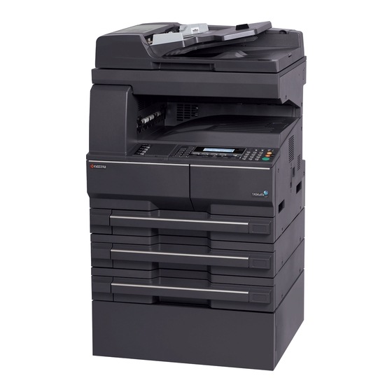
A label shown in the illustration assures that the supplies are our own brand. In this Operation Guide, Taskalfa 181/221 are referred to as 18 ppm model and 22 ppm model respectively. Included Guides The following guides are supplied with the machine. -
Page 3: Safety Conventions In This Guide
Safety Conventions in This Guide The sections of this guide and parts of the machine marked with symbols are safety warnings meant to protect the user, other individuals and surrounding objects, and ensure correct and safe usage of the machine. The symbols and their meanings are indicated below.
-
Page 4: Table Of Contents
Contents Contents Part Names Operation Panel …………. 1-2 Machine.
-
Page 5
Contents Print Configuration …………5-24 Print Quality. -
Page 6
Caution / Warning Labels Caution / Warning labels have been attached to the machine at the following locations for safety purposes. Be sufficiently careful to avoid fire or electric shock when removing a paper jam or when replacing toner. Label 2 High temperature inside. -
Page 7: Installation Precautions
Installation Precautions Environment CAUTION Avoid placing the machine on or in locations which are unstable or not level. Such locations may cause the machine fall down or fall over. This type of situation presents a danger of personal injury or damage to the machine.
-
Page 8: Other Precautions
• Avoid poorly ventilated locations. If the floor is delicate against casters, when this machine is moved after installation, the floor material may be damaged. During copying, some ozone is released, but the amount does not cause any ill effect to one’s health. If, however, the machine is used over a long period of time in a poorly ventilated room or when making an extremely large number of copies, the smell may become unpleasant.
-
Page 9: Precautions For Use
Precautions for Use Cautions when using the machine WARNING Do not place metallic objects or containers with water (flower vases, flower pots, cups, etc.) on or near the machine. This type of situation presents a danger of fire or electrical shock should they fall inside. Do not remove any of the covers from the machine as there is a danger of electrical shock from high voltage parts inside the machine.
-
Page 10: Cleaning
CAUTION Do not pull the power cord when removing it from the outlet. If the power cord is pulled, the wires may become broken and there is a danger of fire or electrical shock. (Always grasp the power plug when removing the power cord from the outlet.) Always remove the power plug from the outlet when moving the machine.
-
Page 11: Machine
Cautions when handling consumables CAUTION Do not attempt to incinerate the toner container or the waste toner box. Dangerous sparks may cause burns. Keep the toner container and the waste toner box out of the reach of children. If toner happens to spill from the toner container or the waste toner box, avoid inhalation and ingestion, as well as contact with your eyes and skin.
-
Page 12: Safety Of Laser Beam
SAFETY OF LASER BEAM 1. Safety of laser beam This machine has been certified by the manufacturer to Class 1 level under the radiation performance standards established by the U.S.DHHS (Department of Health and Human Services) in 1968. This indicates that the product is safe to use during normal operation and maintenance. The laser optical system, enclosed in a protective housing and sealed within the external covers, never permits the laser beam to escape.
-
Page 13: Optical Unit
3. Optical unit When checking the optical unit, avoid direct exposure to the laser beam, which is invisible. Shown at below is the label located on the cover of the optical unit. 4. Maintenance For safety of the service personnel, follow the maintenance instructions in the other section of this manual. 5.
-
Page 14: Safety Instructions Regarding The Disconnection Of Power
Safety Instructions Regarding the Disconnection of Power Caution: The power plug is the main isolation device! Other switches on the equipment are only functional switches and are not suitable for isolating the equipment from the power source. Attention: Le débranchement de la fiche secteur est le seul moyen de mettre l’appareil hors tension. Les interrupteurs sur l’appareil ne sont que des interrupteurs de fonctionnement: ils ne mettent pas l’appareil hors tension.
-
Page 15
(1) year, or 150,000 copies/prints from date of installation, whichever first occurs. In the event the MFP or an accessory is found to be defective within the warranty period, Kyocera’s only obligation and the Customer’s exclusive remedy shall be replacement of any defective parts. -
Page 16
Legal Restriction on Copying/Scanning • It may be prohibited to copy/scan copyrighted material without permission of the copyright owner. • Copying/Scanning the following items is prohibited and may be penalized by low. It may not be limited to these items. Do not knowingly copy/scan the items that are not to be copied/ scanned. -
Page 17: Legal And Safety Information
Legal and Safety Information Please read this information before using your machine. This chapter provides information on the following topics. • Legal Information …………xvi • Regarding Trade Names……….xvii • Energy Saving Control Function ……..xix • Automatic 2-Sided Copy Function …….. xix •…
-
Page 18: Legal Information
Legal Information Copying or other reproduction of all or part of this guide without the prior written consent of Kyocera Mita Corporation is prohibited. OPERATION GUIDE…
-
Page 19: Regarding Trade Names
Regarding Trade Names • PRESCRIBE and ECOSYS are trademarks of Kyocera Corporation. • KPDL and KIR (Kyocera Image Refinement) are trademarks of Kyocera Corporation. • Diablo 630 is a product of Xerox Corporation. • IBM Proprinter X24E is a product of International Business Machines Corporation.
-
Page 20
Monotype Imaging License Agreement Software shall mean the digitally encoded, machine readable, scalable outline data as encoded in a special format as well as the UFST Software. You agree to accept a non-exclusive license to use the Software to reproduce and display weights, styles and versions of letters, numerals, characters and symbols (Typefaces) solely for your own customary business or personal purposes at the address stated on the registration card you return to Monotype Imaging. -
Page 21: Energy Saving Control Function
Energy Saving Control Function The device comes equipped with a Low Power Mode where energy consumption is reduced after a certain amount of time elapses since the device was last used, as well as a Sleep Mode where printer and fax functions remain in a waiting state but power consumption is still reduced to a minimum when there is no activity with the device within a set amount of time.
-
Page 22: About This Operation Guide
About this Operation Guide This Operation Guide contains the following chapters. Chapter 1 — Part Names Identifies machine parts and operation panel keys. Chapter 2 — Preparation before Use Explains adding paper, placing originals, connecting the machine, and necessary configurations before first use. Chapter 3 — Basic Operation Describes the basic procedures of simple copying and printing.
-
Page 23: Conventions In This Guide
Conventions in This Guide The following conventions are used depending on the nature of the description. Convention Description Example Bold Indicates the operation panel Press the Start key. keys or a computer screen. Italic Indicates a message displayed Ready to copy is displayed. on the touch panel.
-
Page 24: Originals And Paper Sizes
Originals and Paper Sizes This section explains the notation used in this guide when referring to sizes of originals or paper sizes. As with A4, B5 and Letter, which may be used either in the horizontal or vertical direction, horizontal direction is indicated by an additional letter R in order to indicate the orientation of the original/paper.
-
Page 25: Part Names
1 Part Names This chapter identifies the machine parts and operation panel keys. • Operation Panel …………1-2 • Machine …………….1-6 OPERATION GUIDE…
-
Page 26: Operation Panel
Part Names Operation Panel 12 13 Ready to copy . Auto Auto 100% 9 10 15 16 14 System Menu/Counter key and indicator Copy key and indicator Print key and indicator Scan key and indicator Fax key and indicator Combine key and indicator Border Erase key and indicator Duplex key and indicator Offset key and indicator…
-
Page 27: Initial Mode
Part Names Lighter key / Darker key Message display Ready indicator (green) Data indicator (green) Attention indicator (red) Logout key Interrupt key and indicator Energy Saver key and indicator Power key and indicator Numeric keys Reset key Stop/Clear key Start key and indicator Main power indicator Initial mode Initial mode is the state that the machine enters at the end of warm-up or when the Reset key is pressed.
-
Page 28: Message Display
Part Names Automatic Cassette Switching Function If multiple cassettes contain the same size paper and the paper in one cassette runs out during copying, the automatic cassette switching function will switch paper feed from the empty cassette to the other cassette that still contains paper.
-
Page 29
Part Names Printer Basic Screen Ready CANCEL MENU This screen is displayed when the Print key is pressed. Reference number Meaning Indicates the current status of the machine and displays the message for required operation. Select to switch between online and offline, to print/resume printing, to clear a specific error, and to begin a new page to forcibly print the last page that waits for printing. -
Page 30: Machine
Part Names Machine Original cover Output tray Operation panel Cassette 1 Paper width adjusting tab Paper length adjusting tab Left cover handle MP tray MP tray extension Slider OPERATION GUIDE…
-
Page 31
Part Names Platen Original size indicator plates Left cover Waste toner box Toner container release lever Toner container Charger cleaner rod Front cover OPERATION GUIDE… -
Page 32
Part Names Main power switch Main power switch cover Handles for transport USB interface connector Network interface connector Memory card slot OPERATION GUIDE… -
Page 33: Preparation Before Use
2 Preparation before Use This chapter explains the preparations before using this equipment for the first time as well as the procedures for loading papers and originals. • Check bundled items …………2-2 • Determining the Connection Method and Preparing Cables ..2-3 •…
-
Page 34: Check Bundled Items
Documents Contained in the Included CD-ROM The following documents are contained in the included CD-ROM (Product Library). Refer to them as necessary. Documents KYOCERA COMMAND CENTER Operation Guide Printer Driver User Guide Network FAX Driver Operation Guide KM-NET for Direct Printing Operation Guide…
-
Page 35: Determining The Connection Method And Preparing Cables
Preparation before Use Determining the Connection Method and Preparing Cables Check the method to connect the equipment to a PC or network, and prepare the necessary cables. Connection Example Determine the method to connect the equipment to a PC or network by referring to the illustration below. Connecting a scanner to your PC network with a network cable (100BASE-TX or 10BASE-T) COMMAND CENTER…
-
Page 36: Preparing Necessary Cables
Preparation before Use Preparing Necessary Cables The following interfaces are available to connect the equipment to a PC. Prepare the necessary cables according to the interface you use. Available Standard Interfaces Function Interface Necessary Cable Printer/Scanner* Network interface LAN (10Base-T or /Network FAX** 100Base-TX, Shielded) Printer…
-
Page 37: Connecting Cables
Preparation before Use Connecting Cables Connecting LAN Cable (Optional) Follow the steps below to connect a LAN cable to the machine. When the machine is powered up, first press the Power key on the operation panel. Check that the Power indicator and the memory indicator are off. After this, turn off the main power switch.
-
Page 38: Connecting Usb Cable
Preparation before Use Connecting USB Cable Follow the steps below to connect a USB cable to the machine. When the machine is powered up, first press the Power key on the operation panel. Check that the Power indicator and the memory indicator are off. After this, turn off the main power switch.
-
Page 39: Switching The Language For Display [Language]
Preparation before Use Switching the Language for Display [Language] Select the language displayed on the touch panel. Use the procedure below to select the language. Press the System Menu/Counter key. Press repeatedly until Language appears. System Menu / Counter: The default message language is English. Language MP Tray Setting Press the Enter key.
-
Page 40: Setting Date And Time
Preparation before Use Setting Date and Time Follow the steps below to set the local date and time at the place of installation. When you send an E-mail using the transmission function, the date and time as set here will be printed in the header of the E-mail message.
-
Page 41
Preparation before Use Press to select DST [Summertime] and Date/Time: then press to select On or Off. Time 06:33 Press to select Year and then press Date/Time: to set the current year. Time Zone GMT 00:00 Year 2009 Press to select Month and then press Date/Time: to set the current month. -
Page 42: Registering The Ip Address
Preparation before Use Network (TCP/IP) Setup Registering the IP Address Register the IP address of this machine. NOTE: Prior to the IP address entries, obtain permission from the network administrator. Press the Print key. Press to select MENU, and then press the Ready Enter key.
-
Page 43: Registering The Subnet Mask
Preparation before Use Press the Enter key. Next, set the subnet mask. Registering the Subnet Mask To register the subnet mask, continue the procedure from step 10 above. Press to select Subnet Mask, and then TCP/IP Setting press the Enter key. DHCP IP Address Subnet Mask…
-
Page 44
Preparation before Use Press to select DHCP, and then press the TCP/IP Setting Enter key. Back DHCP IP Address Press to select On, and then press the DHCP Enter key. Back 2-12 OPERATION GUIDE… -
Page 45: Installing Software
Preparation before Use Installing Software Install appropriate software on your PC from the included Product Library CD-ROM (Product Library) if you want to use the printer function of this machine or perform TWAIN transmission or FAX transmission from your PC. NOTE: Installation on Windows XP, Windows 2000, Server 2003 and Windows Vista must be done by a user logged on with administrator privileges.
-
Page 46: Optional Equipment
Preparation before Use Loading Paper Paper can be loaded standardly in a cassette (18 ppm model) or the two cassettes (22 ppm model) and the MP tray. A paper feeder is also available as an option (refer to Optional Equipment on Appendix-2). Before Loading Paper When you open a new package of paper, fan the sheets to separate them slightly prior to loading in the following…
-
Page 47: Loading Paper In The Cassettes
Preparation before Use Loading Paper in the Cassettes Standard paper, recycled paper, and colored paper can be loaded into the cassette. Up to 300 sheets of standard paper (80 g/m ) or 100 sheets of thick paper (90 to 105 g/m ) can be set.
-
Page 48
Preparation before Use Using the paper length guide, move the plate to fit the paper. IMPORTANT: • Make sure that the length guide is flush against the paper. If there is space between the guide and the paper, set the length guide again. •… -
Page 49: Loading Paper In The Mp Tray
Preparation before Use • If the length and width guides are not flush against the paper, a size that is different from the actual size may be displayed on the message display. • When the paper has become wrinkled from moisture and cannot be fed, set the paper so that the wrinkled side is toward the length guide.
-
Page 50
Preparation before Use NOTE: When you load custom size paper, enter the paper size by referring to MP Tray Settings on page 6-28. You can set the MP tray so that when you select the MP tray, the MP Tray Paper size screen is displayed. For the method of setting, refer to MP Tray Settings on page 6-28. -
Page 51
Preparation before Use Insert the paper along the paper width guides into the tray until it stops. IMPORTANT: Keep the side that was closest the package seal facing up. Put only the paper on the MP tray. Do not load more paper than the paper feed capacity of the MP tray. -
Page 52
Preparation before Use Loading Envelopes and Cardstock Up to 5 envelopes may be loaded in the MP tray. Acceptable envelope sizes are as follows. Acceptable Envelope Size Hagaki 148×100 (mm) Oufuku Hagaki 148 × 200 (mm) Youkei 2 162×114 (mm) Youkei 4 235×105 (mm) Monarch… -
Page 53
Preparation before Use When loading the cardstock, open the paper stopper shown in the figure. For landscape form envelopes, close the flap. Insert the envelope all the way along the width guides, keeping the printing side face-down and the edge with the flap facing towards you. For portrait form envelopes, close the flap. -
Page 54: Specifications
Preparation before Use MP Tray Settings Set the following items for feeding paper from the MP (multi-purpose) tray. Paper Size Set the size of paper to be used from the MP tray. You can use irregular size paper by entering the size NOTE: If the paper size is unknown or no special paper size setting is required, select Universal Size.
-
Page 55: Paper Type
Preparation before Use Press to select Other Regular Size, MP Tray Paper Size : and then press the Enter key. Other Regular Size Press to select the paper size, and then Other Regular Size : press the Enter key. The MP Tray Paper type screen is displayed. Proceed to Paper Type described below.
-
Page 56
Preparation before Use Press to select the MP tray paper type, and MP Tray Paper type : then press the Enter key. Plain Transparency The message display returns to the copier basic Preprinted screen. 2-24 OPERATION GUIDE… -
Page 57: Loading Originals
Preparation before Use Loading Originals Follow the steps below to load originals for copying or sending. Placing Originals on the Platen You may place books or magazines on the platen in addition to ordinary sheet originals. In addition, When copying from an original which cannot be set in the document processor, open the document processor and set the original directly on the platen.
-
Page 58: Loading Originals In The Document Processor
Preparation before Use Loading Originals in the Document Processor The optional document processor automatically scans each sheet of multiple originals. Both sides of two-sided originals are scanned. Originals Supported by the Document Processor The document processor supports the following types of originals. •…
-
Page 59
Preparation before Use How to Load Originals IMPORTANT: Before loading originals, be sure that there are no originals left on the original eject table. Originals left on the original eject table may cause the new originals to jam. Adjust the original width guides to fit the originals. NOTE: Before setting originals, make sure that there are no originals remaining on the original eject table. -
Page 60
Preparation before Use IMPORTANT: To keep ejected originals from falling off the machine, open the ejection extension when using large originals such as A3, B4, 11 × 17″ (Ledger), and × 14″ (Legal). When copying from 2-sided originals, the originals are temporarily ejected onto the ejection tray in order to turn them over. -
Page 61: Basic Operation
3 Basic Operation This chapter explains the following operations. • Power On/Off …………..3-2 • Low Power Mode and Auto Low Power Mode ….3-4 • Sleep and Auto Sleep ………..3-5 • Printing from Applications ……….3-6 OPERATION GUIDE…
-
Page 62: Power On/Off
Basic Operation Power On/Off Power On Turn the power of this machine on Open the main power switch cover located on the right side of the machine and turn the main power switch on ( | ). The machine starts to warm up Once warm-up is completed, the Start indicator lights up green Power Off…
-
Page 63
Basic Operation In case of not using the machine for a extended period of time CAUTION: If this machine will be left unused for an extended period (e.g. overnight), turn it off at the main power switch. If the machine will not be used for an even longer period of time (e.g. vacation), remove the power plug from the outlet as a safety precaution. -
Page 64: Low Power Mode And Auto Low Power Mode
Basic Operation Low Power Mode and Auto Low Power Mode Low Power Mode To activate Low Power Mode, press the Energy Saver key. Touch panel and all indicators on the operation panel will go out to save power except the Energy Saver, Power, and main power indicators. This status is referred to as Low Power Mode.
-
Page 65: Sleep And Auto Sleep
Basic Operation Sleep and Auto Sleep Sleep To enter Sleep, press the Power key. All indicators on the operation panel will go out to save a maximum amount of power except the Power indicator. This status is referred to as Sleep. If print data is received during Sleep, the print job is performed while the touch panel remains unlit.
-
Page 66: Printing From Applications
Basic Operation Printing from Applications Follow the steps below to print documents from applications. NOTE: To print the document from applications, install the printer driver on your computer from the supplied CD-ROM (Product Library). Create a document using an application. Click File and select Print in the application.
-
Page 67
Basic Operation NOTE: If you choose Auto Select, papers are supplied automatically from the paper source loaded with paper of optimum size and type. To print on special paper such as envelope or thick paper, place it on the MP tray and select MP Tray. Select paper orientation, either Portrait or Landscape, to match the orientation of the document. -
Page 68
Basic Operation OPERATION GUIDE… -
Page 69: Copying Functions
4 Copying Functions This chapter explains the functions available for copying. • Basic Copying Procedure …………..4-2 • Adjusting Density …………….. 4-3 • Selecting Image Quality …………… 4-4 • Zoom Copying………………4-5 • Collate Copying………………4-8 • Offset Copying ………………4-9 •…
-
Page 70: Basic Copying Procedure
Copying Functions Basic Copying Procedure Follow the steps as below for basic copying. Press the Copy key when the Copy indicator is off. NOTE: If the machine is in the sleep mode, press the Power key and wait for the machine to warm up. Place the originals on the platen or in the optional document processor.
-
Page 71: Adjusting Density
Copying Functions Adjusting Density Use this procedure to adjust the density when copying. Mode Description Auto Density mode The machine detects the density of the original and sets the optimum density. Manual Density mode Adjust the density by pressing the Lighter or Darker key.
-
Page 72: Selecting Image Quality
Copying Functions Selecting Image Quality Select image quality suited to the type of original. The table below shows the quality options. Image quality mode Description Text + Photo For originals with both text and photographs. Text For originals primarily consisting of text. Photo For photos taken with a camera.
-
Page 73: Zoom Copying
Copying Functions Zoom Copying Adjust the magnification to reduce or enlarge the original image. The following zoom options are available. NOTE: When magnification ratio is larger than 201%, the images will be rotated 90° counter-clockwise prior to copying. Auto Zoom Magnification Selection Mode Original images are reduced or enlarged according to the selected paper size.
-
Page 74: Preset Zoom Mode
Copying Functions Manually reduces or enlarges the original image in 1% 25 % increments between 25% and 400%. 200 % The procedure for zoom mode is explained below. Press the Copy key. Place the originals on the platen. Press the Zoom key. Enter the magnification using the numeric keys.
-
Page 75
Copying Functions Press the Zoom key. Press to select the desired maginification, Zoom : and then press the Enter key. 121 : 8.5×14 11×17 The zoom ratio is displayed on the message 100% 78 :8.5×14 8.5×11 display. Press the Start key to start copying. OPERATION GUIDE… -
Page 76: Collate Copying
Copying Functions Collate Copying Since copying in this mode is performed after multiple originals have been scanned and memorized, a required number of collated copy sets can be produced. NOTE: If the optional document processor is installed, you can select whether or not to turn on the collate mode at a default setting.
-
Page 77: Offset Copying
Copying Functions Offset Copying For copying of multiple sets, the orientation of the copies can be changed at the end of each set for easy classification. NOTE: If the optional document processor or finisher is not installed, use this function with collate copying. You can select whether or not to turn on the offset mode at a default setting.
-
Page 78: Staple
Copying Functions Staple Use this feature to staple your finished copies. NOTE: Stapling requires the optional document finisher. Note also that saddle stitching (center stapling) requires the folding unit. The following stapling options and orientations are available. Cassette Paper Cassette Paper Load Direction Load Direction Original Orientation:…
-
Page 79
Copying Functions The procedure for staple mode is explained below. Press the Copy key. Place the originals on the platen. Pressthe Staple key. Press to select the desired stapling Staple : position, and then press the Enter key. Left Top Right Top Press the Start key. -
Page 80: Original Size
Copying Functions Original Size Specify the size of originals being scanned. Be sure to specify the original size when copying non-standard sizes. Selecting an Original Size from Regular Size Use the procedure below to select the original size. Press the Copy key. Place the originals on the platen.
-
Page 81
Copying Functions Press to select Input Size, and then Original Size : press the Enter key. Auto Input Size Press to set the vertical size. Input Size : 2″ You can set the vertical size to 2″ to 11 5/8″ in 1/8″ 2″… -
Page 82: Paper Selection
Copying Functions Paper Selection Select the paper source (cassette or MP tray) that contains the required paper size. Press the Copy key. Place the originals on the platen. If Auto is displayed on the message display, the paper matching the size of the original is selected automatically.
-
Page 83: Mixed Sized Originals
Copying Functions Mixed Sized Originals Using the optional document processor, the originals of different sizes can be loaded in a batch and copied. In this operation, up to 30 originals of different sizes can be placed in the document processor at the same time. Supported Combinations of Originals The supported combinations of originals are as follows.
-
Page 84: Original Orientation
Copying Functions Original Orientation Select the original orientation to use the following functions. • Zoom (XY Zoom) • Duplex • Margin/Centering originals • Border erase • Combine mode • Booklets • Stapling/Punch (optional feature) When placing originals on the platen [Top Edge Top] [Top Edge Left] Original…
-
Page 85
Copying Functions Use the procedure below to select the orientation when placing the originals on the platen. Press the Copy key. Place the originals on the platen. Press the Function key. Press to select Orig. direction, and Function : then press the Enter key. Orig. -
Page 86: Ecoprint
Copying Functions EcoPrint Use EcoPrint to save toner when printing. Use this function for test copies or any other occasion where high quality print is unnecessary. NOTE: The copy exposure will be a little lighter. You can select whether or not to turn on the ecoprint mode at a default setting. Refer to EcoPrint Mode on page 6-4.
-
Page 87: Combine Mode
Copying Functions Combine Mode This mode allows you to copy 2 or 4 originals combined onto a single page. 2-in-1 mode or 4-in-1 mode. The page boundary of each original can be indicated. NOTE: Both the original size and the copy paper size must be regular sizes. 2-in-1 Mode For copying two originals onto a single sheet.
-
Page 88: Types Of Page Boundary Lines
Copying Functions 4-in-1 Mode For copying four originals onto a single sheet. This mode can be used with Duplex mode to copy eight originals onto one sheet. The following 4-in-1 options and output orientations are available. Original Copy Orientation of Original Platen Document processor NOTE:…
-
Page 89
Copying Functions Press the Combine key. Press to select the desired combine Combine : copying mode, and then press the Enter key. 2 in 1 4 in 1 (Z) 4 in 1 (N) Press to select the type of the lines to Border Line: indicate page boundaries, and then press the None… -
Page 90: Margin Mode
Copying Functions Margin Mode Shift the original image to make space on the copy for binding on the left (right) or top (bottom) side. The following margin widths are available. Input units Margin Width Inch Models 1/8 to 3/4″ (in 1/8″ increments) Metric Models 1 mm to 18 mm (in 1 mm increments) NOTE:…
-
Page 91: Border Erase
Copying Functions Border Erase Use Border Erase to remove black shadows that appear around the outside of the original when making copies. The following options can be selected. Sheet Erase Erases black borders around the single sheet original. Original Copy Book Erase Erases black borders around the edges and in the middle of the original such as a thick book.
-
Page 92
Copying Functions Press to set the border erase width, and Border Erase Width : then press the Enter key. 1/4″ 1/8″ 3/4″ You can set the width to 1/8″ to 3/4″ in 1/8″ increments [1 mm to 18 mm in 1 mm increments]. Press the Start key to start copying. -
Page 93: Duplex Copying
Copying Functions Duplex Copying Produce two-sided copies. The following duplex options are available. You can also create single-sided copies from two-sided originals or originals with facing pages such as books. The following modes are available. One-sided to Two-sided Produces two-sided copies from one-sided originals. In case of an odd number of originals, the back side of the last copy will be blank.
-
Page 94
Copying Functions Book to One-sided Produces a 1-sided copy of a 2-sided or open book original. Original Copy Book to Two-sided Produces two-sided copies from an open book original with facing pages. NOTE: The original sizes that can be used are A3, B4, A4R, B5R, A5R, 11 x 17″… -
Page 95
Copying Functions Scanning of the original is performed. After scanning all originals, press the Enter key to start copying. OPERATION GUIDE 4-27… -
Page 96: Continuous Scan
Copying Functions Continuous Scan The continuous copying function allows multiple originals to be separated into some blocks, to be scanned at more than one time, and to be copied in one batch. Since multiple originals of the same type are scanned in multiple steps to accumulate data in memory, many originals can be copied in one batch.
-
Page 97: Auto Image Rotation
Copying Functions Auto Image Rotation Automatically rotates the image when the sizes of the original and the loaded paper matches but the orientations are different. The images will be rotated 90° counter-clockwise prior to copying. NOTE: The paper sizes that can be used for auto rotation are A4/11 x 8 «…
-
Page 98: Interrupt Mode
Copying Functions Interrupt Mode This function allows you to pause the current jobs in progress when you need to make copies immediately. When interruption copy ends, the machine resumes the paused print jobs. The following modes are available for the interrupt function. Mode Description Interrupt copy…
-
Page 99
Copying Functions During Output The procedure for using Interrupt Mode during output is explained below. Press the Interrupt key during output. Select Interrupt mode is displayed. NOTE: If the machine has neither print data nor received fax data, Interrupt mode OK [Interrupt mode] is displayed. -
Page 100: Program Function
Copying Functions Program Function After registering sets of frequently used functions as a single program, you can simply press the program number as needed to recall those functions. You can also name the programs for easy identification when recalling. Registering Programs Use the procedure below to register a program.
-
Page 101: Printing Functions
5 Printing Functions This chapter explains the settings required for using the printing functions. For setting operation required for using this machine as a network printer, use the operation panel. The principal settings that can be made are shown below. •…
-
Page 102: Using This Machine As A Network Printer
Printing Functions Using This Machine as a Network Printer To use this machine as a network printer, use the procedure below for the setting Preparation of network connection environment (Assignment of IP address, etc.) Connection of network cable (Refer to Connecting Cables on page 2-5.) Setting operation from the operation panel of this machine (See this chapter.) Principal setting items •…
-
Page 103: Status Page Printing
Printing Functions Status Page Printing The printer default settings, the memory capacity, and so on are printed in a list. Use the procedure below to print the status page. Press the Print key. Press to select MENU, and then press the Ready Enter key.
-
Page 104: E-Mps Function
Printing Functions e-MPS Function The following items can be set in e-MPS function setting. • Printing Quick Copy/Proof-and-Hold • Deleting Quick Copy/Proof-and-Hold • Printing Private Print/Stored Job • Deleting Private Print/Stored Job • Printing Virtual Mailbox Accumulated Data • Printing Virtual Mailbox List •…
-
Page 105
Printing Functions Printing Quick Copy/Proof-and-Hold If you set quick copy with the printer driver when printing a document, the data is printed and stored in the hard disk. When printing is required, you can print a required number of copies from the operation panel. If you set proof-and-hold with the printer driver and set the required number of copies to execute printing, only one set is output and the document data is stored in the hard disk. -
Page 106
Printing Functions Printing Private Print/Stored Job In private printing, you can execute printing by using the operation panel to input the four-digit access code that has been set with the printer driver when printing from your computer. The data is cleared after printing is complete. -
Page 107: Printing Virtual Mailbox Accumulated Data
Printing Functions Press to select Delete, and then press the Select User Name Enter key. Copies Delete Printing Virtual Mailbox Accumulated Data With the virtual mailbox function, a job is stored in the virtual mailbox. If you use the virtual mailbox function to print a document with the printer driver, the job is stored and is not printed until you execute printing from the operation panel.
-
Page 108: Printing Code Job List
Printing Functions Press to select Print, and then press the List of VMB Enter key. Print The virtual mailbox list is printed. Printing Code Job List Permanent code jobs in the hard disk can be printed. Display the e-MPS screen. (See How to Display the e-MPS Screen on page 5-4.) Press to select List of code Job, and…
-
Page 109
Printing Functions Capacity for Storage of Temporary Code Jobs Set the total capacity (upper limit) for storage of temporary code jobs in the hard disk. The actual maximum size, however, is the size of available hard disk space. Display the e-MPS screen. (See How to Display the e-MPS Screen on page 5-4.) Press to select e-MPS Configuration,… -
Page 110
Printing Functions Total Capacity for Storage of Virtual Mailboxes Set the total capacity (upper limit) for storage of virtual mailboxes in the hard disk. The actual maximum size, however, is the size of available hard disk space. Display the e-MPS screen. (See How to Display the e-MPS Screen on page 5-4.) Press to select e-MPS Configuration,… -
Page 111: Interface
Printing Functions Interface This machine is equipped with a USB interface and network interface as standard components. How to Display the Interface Screen Press the Print key. Press to select MENU, and then press the Ready Enter key. CANCEL MENU Press to select Interface, and then Menu…
-
Page 112
Printing Functions Press to select Change #, and then press NetWare the Enter key. Change # Press to select the frame mode, and then NetWare Frame press the Enter key. Back Auto 802.3 Press the Reset key. The message display returns to the printer basic screen. -
Page 113
Printing Functions Press to select Network, and then press Interface the Enter key. Back Network Press to select TCP/IP, and then press the Network Setting Enter key. Back NetWare TCP/IP Press to select On, and then press the TCP/IP Enter key. Back DHCP This machine supports DHCP (Dynamic Host Configuration Protocol). -
Page 114
Printing Functions Press to select Change #, and then press TCP/IP the Enter key. Change # Press to select IP Address, and then TCP/IP Setting press the Enter key. Back DHCP IP Address Enter the IP address using the numeric keys. IP Address Enter the first block of 3 digits of the address in the highlighted area. -
Page 115
Printing Functions Use the same procedure as steps 4 to 6 of IP Gateway Address setting to input the address, and then press the Enter key. When you finish making all of the setting, press the Reset key. The message display returns to the printer basic screen. -
Page 116: Emulation
Printing Functions Emulation NOTE: You can set the emulation for each interface. Emulation Mode Selection Emulation modes that can be used with this machine: PCL6, KC-GL, KPDL, KPDL (AUTO), Line Printer, IBM Proprinter, Diablo 630, EPSON LQ-850 If you set KC-GL, you can set the thickness of the pen and the page size. If you set KPDL (AUTO), switching between KPDL and an alternative emulation mode will be automatically performed according to the print data.
-
Page 117
Printing Functions KC-GL Pen Thickness If you have selected the KC-GL emulation, you can set the thicknesses of the eight pens and the page size. Continue the procedure from step 5 of Emulation Mode Selection to set these items as shown below. Press to select KC-GL Pen Adjust, and KC-GL… -
Page 118
Printing Functions Press to select On or Off, and then press Print KPDL Errs the Enter key. Back If you set On, the details of any error will be printed. Press the Reset key. The message display returns to the printer basic screen. -
Page 119: Font
Printing Functions Font You can select the default font for the current interface. The default font can be one of the internal fonts or a font stored in the optional memory card. You can set the following items for fonts. •…
-
Page 120: Font Size
Printing Functions Press to select the font ID, and then press Select Font the Enter key. Back I000 Detail The font number is displayed. Font ID I000 Characters displayed before font numbers indicate the following items. Display Description Internal font Downloaded fonts Fonts in memory card Fonts in RAM disk or optional hard disk…
-
Page 121
Printing Functions Press to select Detail, and then press the Select Font Enter key. I000 Back I000 Detail Press to enter the character size, and then Font Size Setting press the Enter key. 8.50 Point (4.00 999.75) You can set the character size to 4.00 to 999.75 point. -
Page 122: Code Set Selection
Printing Functions Courier/Letter Gothic Font Setting You can select the thickness of the Courier or Letter Gothic font from two types. An example of changing the Courier font thickness is described below. Display the Font screen. (See How to Display the Font Screen on page 5-19.) Press to select Select Font, and then…
-
Page 123: Font List Printing
Printing Functions Press the Reset key. The message display returns to the printer basic screen. Font List Printing Display the Font screen. (See How to Display the Font Screen on page 5-19.) Press to select List of Inter. Fonts, Font and then press the Enter key.
-
Page 124: Print Configuration
Printing Functions Print Configuration You can set the following items for print configuration. • Number of Copies • Reduction Printing • Print Orientation • Page Protect Mode • Line Feed (LF) Action • Carriage Return (CR) Action • Wide A4 NOTE: You can set the print configuration for each interface.
-
Page 125: Reduction Printing
Printing Functions Press to enter the number of copies, and Copies then press the Enter key. You can set any number from 1 to 999. Press the Reset key. The message display returns to the printer basic screen. Reduction Printing If you specify the paper size (original size) and the output size, the machine reduces the image at a preset magnification ratio to print onto the specified output size paper.
-
Page 126: Page Protect Mode
Printing Functions Press to select Portrait or Landscape, Orientation and then press the Enter key. Back Portrait Landscape Press the Reset key. The message display returns to the printer basic screen. Page Protect Mode To maintain the printer memory efficiently, the default setting of this mode is Auto. Normally, this menu is not displayed.
-
Page 127: Carriage Return (Cr) Action
Printing Functions return. Ignore LF: Does not perform a line feed. Press the Reset key. The message display returns to the printer basic screen. Carriage Return (CR) Action Set the action of the machine to be executed when it receives a carriage return code (0DH). Display the Page Set screen.
-
Page 128
Printing Functions Press the Reset key. The message display returns to the printer basic screen. 5-28 OPERATION GUIDE… -
Page 129: Print Quality
Printing Functions Print Quality You can set the following items for print quality. • KIR Mode • EcoPrint Setting • Resolution Setting • Print Density How to Display the Print Quality Screen Press the Print key. Press to select MENU, and then press the Ready Enter key.
-
Page 130: Ecoprint Setting
Printing Functions EcoPrint Setting The ecoprint mode allows printing with less toner consumption. Use this mode when high quality printing is not necessary, for example, for trial printing. Display the Print Quality screen. (See How to Display the Print Quality Screen on page 5-29.) Press to select EcoPrint Mode, and then Print Quality…
-
Page 131
Printing Functions Press to select Print Density, and then Print Quality press the Enter key. EcoPrint Mode Resolution Print Density Press to set the print density, and then Print Density press the Enter key. Press the Reset key. The message display returns to the printer basic screen. -
Page 132: Memory Card Operation
Printing Functions Memory Card Operation If the optional memory card is installed in this machine, the following operations are available. • Reading Font Data • Reading Macro Data • Reading Data • Reading Program • Writing Data • Deleting Data •…
-
Page 133: Reading Macro Data
Printing Functions Press the Reset key. The message display returns to the printer basic screen. Reading Macro Data Display the Memory Card screen. (See How to Display the Memory Card Screen on page 5-32.) Press to select Read Macro, and then Memory Card press the Enter key.
-
Page 134: Writing Data
Printing Functions Press to select the program to read, and then press the Enter key. The selected program is read from the memory card. Press the Reset key. The message display returns to the printer basic screen. Writing Data Display the Memory Card screen. (See How to Display the Memory Card Screen on page 5-32.) Press to select Write Data, and then…
-
Page 135: Deleting Font Data
Printing Functions The selected data is deleted from the memory card. Press the Reset key. The message display returns to the printer basic screen. Deleting Font Data Display the Memory Card screen. (See How to Display the Memory Card Screen on page 5-32.) Press to select Delete Font, and then Memory Card…
-
Page 136: Deleting Language Data
Printing Functions Press to select Delete Macro, and then Memory Card press the Enter key. Delete Font Delete Program Delete Macro Press to select the macro data to delete, and then press the Enter key. The selected macro data is deleted from the memory card.
-
Page 137: Printing A Partition List
Printing Functions Press to select OK, and then press the Enter key. Formatting of the memory card starts. When formatting is complete, format information is output. Printing a Partition List Display the Memory Card screen. (See How to Display the Memory Card Screen on page 5-32.) Press to select List of Partitions, Memory Card…
-
Page 138: Hard Disk Operation
Printing Functions Hard Disk Operation If the optional hard disk is installed in this machine, the following operations are available. • Reading Data • Reading Program • Writing Data • Deleting Data • Deleting Font Data • Deleting Program Data •…
-
Page 139: Ram Disk Operation
Printing Functions RAM Disk Operation RAM Disk Functions This machine is equipped with RAM disk functions. The RAM disk is a virtual disk unit that uses a part of the memory. If you assign a certain size of the memory to the RAM disk, you can use the RAM disk for electronic sorting (for reduction of total print time) and storage and reading of data.
-
Page 140: Ram Disk Size
Printing Functions Press to select RAM Disk Mode, and then Menu press the Enter key. Page Set Print Quality RAM Disk Mode Press to select Change #, and then press RAM Disk Mode the Enter key. The operation procedure of each item is the same Change # as that of the memory card operation.
-
Page 141: Paper Handling
Printing Functions Paper Handling You can set the following items for paper. • MP Tray Mode • Paper Source • Duplex Print Mode • Output Destination • Override A4/Letter How to Display the Paper Handling Screen Press the Print key. Press to select MENU, and then press the Ready…
-
Page 142: Paper Source
Printing Functions Paper Source Set the paper source to be selected first. Display the Paper Handling screen. (See How to Display the Paper Handling Screen on page 5-41.) Press to select Feed Select, and then Paper Handling press the Enter key. Back MP Tray Mode Feed Select…
-
Page 143: Output Destination
Printing Functions Display the Paper Handling screen. (See How to Display the Paper Handling Screen on page 5-41.) Press to select Duplex Mode, and then Paper Handling press the Enter key. MP Tray Mode Feed Select Duplex Mode Press to select Short edge bind or Duplex Mode Long edge bind, and then press the Enter key.
-
Page 144
Printing Functions Override A4/Letter The A4 and Letter sizes can be regarded as a size that can be used in common. Display the Paper Handling screen. (See How to Display the Paper Handling Screen on page 5-41.) Press to select Override A4/LT, and Paper Handling then press the Enter key. -
Page 145: Other Settings
Printing Functions Other Settings You can set the following items for other settings. • Form Feed Timeout • Received Data Dump • Printer Function Resetting • Resource Protect Mode • Auto Continue • Duplex Printing Error Detection • Stapling Error Detection •…
-
Page 146: Received Data Dump
Printing Functions Press the Reset key. The message display returns to the printer basic screen. Received Data Dump You can print data received by this machine as hexadecimal codes for debugging programs and files. Display the Others screen. (See How to Display the Others Screen on page 5-45.) Press to select Print HEX-DUMP, and…
-
Page 147: Resource Protect Mode
Printing Functions Press to select OK, and then press the Printer Reset Enter key. Back The printer functions are reset. Resource Protect Mode The resource protect mode protects the resource data such as downloaded fonts and macros and memorizes the PCL resources even if the emulation mode is switched. If you select Permanent, temporary resources are not protected.
-
Page 148: Auto Continue
Printing Functions Auto Continue If any of the following error messages appears, the error can be cleared and printing can be continued after the preset recovery time elapses (auto continue). • Memory Overflow/Press GO • Print overrun Press GO • KPDL error Press GO •…
-
Page 149: Duplex Printing Error Detection
Printing Functions Press the Reset key. The message display returns to the printer basic screen. Duplex Printing Error Detection This setting is available if the optional duplex unit is installed. You can select whether or not to display Duplex disabled Press GO when you select duplex printing and specify a paper type that cannot be used for duplex printing such as label.
-
Page 150: Stapling Error Detection
Printing Functions Stapling Error Detection You can select whether or not to display Add Staples and Press GO when staples have run out while stapling is performed. Setting Processing • If you select GO, printing is performed without stapling. • If you select CANCEL, printing is cancelled.
-
Page 151
Printing Functions Press to select Service, and then press Others the Enter key. Auto Continue Finishing Error Service Press to select Print Status Page, and Service then press the Enter key. Back Print Status Page Paper Feed Press to select Print, and then press the Print Status Page Enter key. -
Page 152
Printing Functions 5-52 OPERATION GUIDE… -
Page 153: System Menu
6 System Menu This chapter explains the system settings concerning the general operation of this machine. The principal settings that can be made are shown below. • Default Setting Mode …………6-2 • Machine Default Settings ……….6-13 • MP Tray Settings …………6-28 •…
-
Page 154: Default Setting Mode
System Menu Default Setting Mode For this machine, the state that the machine enters at the end of warm-up or when the Reset key is pressed is called initial mode. The settings of this machine that are made automatically in the initial mode are called default settings.
-
Page 155
System Menu Enter the four-digit management code using the Enter Pin Code using # key. numeric keys. The management code at the factory default setting is 1800 for the 18 ppm model and 2200 for the 22 ppm model. NOTE: The four-digit management code can be changed. -
Page 156
System Menu Press to select Orig Image, and then Copy Default : press the Enter key. Density Mode Manual Original Image Txt+Phto Press to select Text+Photo, Text or Original Image : Photo, and then press the Enter key. Text+Photo Text Photo Press the Reset key. -
Page 157
System Menu Press to adjust the background color, and Background Adjustment : then press the Enter key. Moving right darkens the background color, and moving left lightens it. Press the Reset key. The message display returns to the copier basic screen. -
Page 158
System Menu Press to select Off or On, and then press Paper Type(Auto): the Enter key. If you have selected On, press to select the Paper Type(Auto): desired paper type, and then press the Enter key. Plain Preprinted Press the Reset key. The message display returns to the copier basic screen. -
Page 159
System Menu Press to select Default Magnif, and Copy Default : then press the Enter key. Paper Type(Auto ) Plain Default Cassette Casset.1 Default Magnif . 100% Press to select 100% or Auto %, and then Default Magnification : press the Enter key. 100% Auto % Press the Reset key. -
Page 160
System Menu Press to adjust the density, and then press Adjust Auto OCR Density : the Enter key. Moving right darkens the density, and moving left lightens it. Press the Reset key. The message display returns to the copier basic screen. -
Page 161
System Menu Press the Reset key. The message display returns to the copier basic screen. Density Adjustment for Photo Originals Adjust the density of the central value in the manual density mode for photo originals. Display the Copy Default screen. (See How to Display the Copy Default Screen on page 6-2.) Press to select Photo Ori Dnsity, and… -
Page 162
System Menu Offset Copying Select whether or not to set the offset copy mode as a default setting. Display the Copy Default screen. (See How to Display the Copy Default Screen on page 6-2.) Press to select Offset, and then press the Copy Default : Enter key. -
Page 163
System Menu Press to select Margin Width, and then Copy Default : press the Enter key. Offset Auto Rotation Margin Width 1/4″ Press to set the default value of margin Margin Width : width, and then press the Enter key. 1/4″… -
Page 164
System Menu Enter the maximum number of copies (1 to 999) Copy Limit: using the numeric keys, and then press the Enter key. Sets # keys Press the Reset key. The message display returns to the copier basic screen. Black Streaking Reduction Processing If black streaks (streaks that are not contained in the original image) appear on copies from the optional document processor, you can make black streaking less noticeable. -
Page 165: Machine Default Settings
System Menu Machine Default Settings You can set the following items as machine default settings. • Auto Cassette Switching • Paper Size (cassettes 1 to 4) • Paper Type (cassettes 1 to 4) • MP Tray Confirmation Display • Paper Weight for Paper Type •…
-
Page 166
System Menu NOTE: The four-digit management code can be changed. (See Administrator Management Code Change on page 6-24.) If the management code is accepted, the Machine Machine Default : Default screen is displayed. Auto Cassette SW Next, perform the setting referring to the following Paper Size(1st) Auto I description of each setting item. -
Page 167
System Menu NOTE: For the 18 ppm model, cassettes 2 to 4 are included in the optional paper feeder. For the 22 ppm model, cassettes 3 and 4 are included in the optional paper feeder. This setting is displayed only if the optional paper feeder is installed. -
Page 168
System Menu Press the Reset key. The message display returns to the copier basic screen. MP Tray Confirmation Display Select whether or not to display the MP Tray Paper size screen when pressing the Paper Selection key to select the multi-purpose tray. Display the Machine Default screen. -
Page 169
System Menu Press to select the paper weight, and then Plain: press the Enter key. Heavy 1 Middle 3 Middle 2 When all setting is complete, press to select Paper type (Paper Weight ): End, and then press the Enter key. Plain Middle 2 Transparency… -
Page 170
System Menu Custom Paper Type Printing onto prepunched paper, preprinted paper or letterhead in the one-sided mode and the two-sided mode from the same paper source may cause displacement of hole positions or reverse orientations on both sides in two-sided printing. Set Match Print Direction to match the orientation in one-sided printing and two-sided printing. -
Page 171
System Menu Original Orientation Set the default original orientation. Display the Machine Default screen. (See How to Display the Machine Default Screen on page 6-13.) Press to select Orig. direction, and Machine Default : then press the Enter key. P. Type (2sided) Specific P . -
Page 172: Top Tray
System Menu Press the Reset key. The message display returns to the copier basic screen. Auto Low Power Time Set the time that elapses before the low power mode is automatically activated. Time that can be set: Inch Specification— 1 to 240 minutes (in 1 minute increments) Metric Specification—…
-
Page 173: Job Separator
System Menu Press to select Copy Otput Destn, and Machine Default : then press the Enter key. Sleep Mode Time 1 Min. Low Power Time 1 Min. Copy Otput Destn Top Tray Press to select the desired output Copy Output Destination : destination, and then press the Enter key.
-
Page 174
System Menu Default Operation Mode Select the default screen to be displayed when the power is turned on from the copy screen or the fax screen. NOTE: This item is displayed only if the optional fax kit is installed. Display the Machine Default screen. (See How to Display the Machine Default Screen on page 6-13.) Press to select Main mode, and then press… -
Page 175
System Menu Date and Time Set the current date and time, time difference from the Greenwich Mean Time (GMT), and summer time. Display the Machine Default screen. (See How to Display the Machine Default Screen on page 6-13.) Press to select Date/Time, and then press Machine Default : the Enter key. -
Page 176
System Menu Press the Reset key. The message display returns to the copier basic screen. Display Contrast Adjustment Adjust the display contrast if the message display is indistinct. Display the Machine Default screen. (See How to Display the Machine Default Screen on page 6-13.) Press to select Display Contrast Machine Default :… -
Page 177
System Menu Press the Reset key. The message display returns to the copier basic screen. Auto Sleep The machine enters automatically the sleep mode when the preset time elapses without any operation if this setting is turned On. NOTE: This setting is displayed only on the inch specification machine. You can disable the auto sleep function if this function causes inconvenience. -
Page 178
System Menu Press the Reset key. The message display returns to the copier basic screen. Auto Clear Time Set the time that elapses from completion of copying to activation of the auto clear function if you have turned On the auto clear function (see page 6-25.) Time that can be set: 10 to 270 seconds (in 10 second increments) NOTE: This item is not displayed if the auto clear function is off. -
Page 179
System Menu Press the Reset key. The message display returns to the copier basic screen. Machine Administrator Management Code Change You can change the four-digit management code for the security administrator of the other machine. IMPORTANT: If you change the management code, be sure to note it. If you should forget the management code, contact your service representative. -
Page 180: Mp Tray Settings
System Menu MP Tray Settings Set the following items for feeding paper from the MP tray. Paper Size Set the size of paper to be used from the MP tray. You can use irregular size paper by entering the size. NOTE: If the paper size is unknown or no particular paper size setting is required, select Universal Size.
-
Page 181
System Menu Press to select Other Regular Size, MP Tray Paper Size : and then press the Enter key. Other Regular Size Press to select the paper size, and then Other Regular Size : press the Enter key. The MP Tray Paper type screen is displayed. Proceed to MP Tray Paper Type described below. -
Page 182
System Menu Paper Type To set the paper type to be used in the MP tray, continue the procedure from Paper Size setting. Paper types that can be set: Plain, Transparency, Preprinted, Labels, Bond, Recycled, Vellum, Rough, Letterhead, Color [Colour], Prepunched, Envelope, Cardstock, Thick paper, High quality, Custom 1 (to Press to select the paper type, and then press…
 -
Page 183: Browsing And Printing The Total Counter
System Menu Browsing and Printing the Total Counter You can browse the total count on the operation panel. Also you can output it as a counter report. Browsing the Total Counter NOTE: You can browse the output counter and the scanning counter. Press the System Menu/Counter key.
-
Page 184
System Menu Press the Reset key. The message display returns to the copier basic screen. 6-32 OPERATION GUIDE… -
Page 185: Report Output
System Menu Report Output You can output the following reports from the operation panel. Copy status report Machine status report Coverage report NOTE: Ensure that A4/11 » paper is set in the cassette when printing a report. × A coverage report is a report on which the number of printed sheets and the average of blackness ratio for each paper size are written.
-
Page 186: Language Setting
System Menu Language Setting You can select the language to be used on the message display. Languages that can be selected: Inch Specification — English, French (Français), Spanish (Español), and Japanese ( Metric Specification — English, German (Deutsch), French (Français), Spanish (Español) and Italian (Italiano) Press the System Menu/Counter key.
-
Page 187: Job Accounting
7 Job Accounting This chapter explains the job accounting functions of this machine. The principal functions that can be set are shown below. • Job Accounting Mode ………..7-2 • All Account Management ……….7-10 • Individual Account Management……… 7-11 • Enabling Job Accounting ……….7-12 •…
-
Page 188: Job Accounting Mode
Job Accounting Job Accounting Mode Use the job accounting mode to control the total number of copies and prints by setting an ID-code for each account. The job accounting mode of this machine has the following features. • Controls the copier functions, printer functions, and optional scanner/fax functions using the same ID- codes.
-
Page 189: Managing Accounts
Job Accounting How to Display the Job Accounting Screen Use the following procedure to display the Job Accounting screen. Press the System Menu/Counter key. Press to select Job Accounting, and System Menu / Counter: then press the Enter key. Counter Check Print Report Job Accounting Enter the four-digit management code using the…
-
Page 190: Setting Limit Of Use
Job Accounting Enter a one- to eight-digit ID-code using the New registration : numeric keys. Account ID A code from 0 to 99999999 can be input. NOTE: If you try to register an ID-code that has been already input, an error occurs. Enter another ID-code. Press the Enter key.
-
Page 191
Job Accounting Item Description of limit Reference page Fax transmission Set the limit of count of fax transmission if the optional fax kit is limit installed. No limit: Does not set the limit of count of fax transmission. Counter limit: Set the limit of count of fax transmission (0 to 999,999). -
Page 192
Job Accounting Press to select Able to use or Unable Printer: to use, and then press the Enter key. Able to use Unable to use The message display returns to the Limit in use screen. Output Limit You can set the limit of total count of copying and printing. NOTE: This item is not displayed if both Copy Restriction and Print Restriction are set to Unable to use. -
Page 193
Job Accounting Press to select No limit or Counter Scanner Transmitting : limit or Is not permitted, and then press the No Limit Enter key. Counter Limit Is not permitted If you have selected Counter limit, the Counter limit Default Value screen is displayed. Proceed to the next step. -
Page 194: Deleting An Account
Job Accounting Deleting an Account Delete a registered account. Display the Job Accounting screen. (See How to Display the Job Accounting Screen on page 7-3.) Press to select Edit Job Accounting, Job Accounting : and then press the Enter key. Each Job Accounting TL Edit Job Accounting Job Accountg Def .
-
Page 195
Job Accounting Press to select Edit Job Accounting, Job Accounting : and then press the Enter key. Each Job Accounting TL Edit Job Accounting Job Accountg Def . Set. Press to select Change limit in use, Edit Job Accounting : and then press the Enter key. -
Page 196: All Account Management
Job Accounting All Account Management You can browse the total output count, output the job accounting report, and clear the counter for all accounts. Display the Job Accounting screen. (See How to Display the Job Accounting Screen on page 7-3.) Press to select Job Accounting Total, Job Accounting :…
-
Page 197: Individual Account Management
Job Accounting Individual Account Management You can see the output count and clear the counter for individual accounts. Display the Job Accounting screen. (See HHow to Display the Job Accounting Screen on page 7-3.) Press to select Each Job Accounting Job Accounting : TL, and then press the Enter key.
-
Page 198: Enabling Job Accounting
Job Accounting Enabling Job Accounting Turn on or off the job accounting function. Display the Job Accounting screen. (See How to Display the Job Accounting Screen on page 7-3.) Press to select Job Accounting On/ Job Accounting : Off, and then press the Enter key. Edit Job Accounting Job Accountg Def .
-
Page 199: Default Settings
Job Accounting Default Settings Adjust the default settings for job accounting. You can set the following items in default settings. • Copier Job Accounting (page 7-13) • Printer Job Accounting (page 7-14) • Scanner Job Accounting (page 7-14) • Fax Job Accounting (page 7-15) •…
-
Page 200: Printer Job Accounting
Job Accounting Printer Job Accounting You can select whether or not to enable job accounting for the printer functions. Display the Job Accounting screen. (See How to Display the Job Accounting Screen on page 7-3.) Press to select Job Accounting Def. System Menu / Counter: Set, and then press the Enter key.
-
Page 201: Fax Job Accounting
Job Accounting Press to select Off or On, and then press Scanner Job Accounting : the Enter key. Press to select End, and then press the Job Accounting Default Setting Enter key. Copy Job Account . : On Prnt Job Account . : On Fax Job Accounting You can select whether or not to enable job accounting for the fax functions.
-
Page 202
Job Accounting Press to select Job Accounting Def. Job Accounting : Set, and then press the Enter key. Each Job Accounting TL Edit Job Accounting Job Accountg Def . Set. Press to select Excess limit Set, and Job Accounting Default Setting then press the Enter key. -
Page 203: Using Job Accounting
Job Accounting Using Job Accounting Copier Operation Under job accounting, you can perform copier operation only by entering your ID-code using the numeric keys. IMPORTANT: Be sure to press the Job Accounting key after completing copying. The ID-code input screen is displayed.
-
Page 204
Job Accounting 7-18 OPERATION GUIDE… -
Page 205: Maintenance
8 Maintenance This chapter describes cleaning and toner replacement. • Cleaning…………….8-2 • Toner Container and Waste Toner Box Replacement …8-6 OPERATION GUIDE…
-
Page 206: Cleaning
Maintenance Cleaning Clean the machine regularly to ensure optimum output quality. CAUTION: For safety, always unplug the power cord before cleaning the machine. Original Cover / Glass Platen Wipe the backside of the original cover and the glass platen with a soft cloth dampened with alcohol or mild detergent.
-
Page 207
Maintenance Open the document processor and wipe the slit glass (a). Wipe the white guide (b) on the document processor. Separator Clean the separator regularly (at least monthly) to ensure optimum output quality. Open the front cover. Remove cleaning brush (blue colored). OPERATION GUIDE… -
Page 208: Transfer Roller
Maintenance Pull up and open left cover. As shown in the figure, clean dirt from the separator by moving the brush from side to side along the separator. Put away the cleaning brush, press the specified position of the front cover and left cover to close. Transfer Roller Open the front cover.
-
Page 209
Maintenance Pull up and open left cover. As shown in the figure, clean dirt from the transfer roller by moving the brush from side to side along the roller while rotating the roller by turning the gear at the left end of the roller. Put away the cleaning brush, press the specified position of the front cover and left cover to close. -
Page 210: Toner Container And Waste Toner Box Replacement
Maintenance Toner Container and Waste Toner Box Replacement When the touch panel displays Add toner, replace the toner. Every time you replace the toner container, be sure to clean the parts as instructed below. Dirty parts may deteriorate output quality. CAUTION: Do not attempt to incinerate the toner container or the waste toner box.
-
Page 211
Maintenance WARNING: High voltage is present in the charger section. Take sufficient care when working in this area, as there is a danger of electrical shock. IMPORTANT: Do not invert the old waste toner box. Use the cap attached to the center of the old waste toner box to cover the opening. -
Page 212: Cleaning Electrical Charge Section
Maintenance Place the old toner container in the plastic bag provided for disposal. Cleaning Electrical Charge Section While holding the charger cleaner rod, gently pull it out as far as it will go and push it in again. Repeat this operation two or three times. NOTE: Do not use excessive force to pull the rod or attempt to pull it out completely.
-
Page 213
Maintenance When the electrical charge section is pulled out approximately 5 cm (2 inches), remove the grid cleaner and then push back the electrical charge section all the way into the main body. IMPORTANT: After you use the grid cleaner to clean the electrical charge section, the machine can be used again after more than 5 minutes have elapsed. -
Page 214
Maintenance Insert the new toner container, and push it with both hands until it is locked. Install the new waste toner box. Close the front cover. NOTE: Return the exhausted toner container and waste toner box to your dealer or service representative. -
Page 215: Troubleshooting
9 Troubleshooting This chapter explains how to solve problems with the machine. • Solving Malfunctions ………….9-2 • Responding to Error Messages ……..9-5 • Clearing Paper Jams ……….9-12 OPERATION GUIDE…
-
Page 216: Solving Malfunctions
Troubleshooting Solving Malfunctions The table below provides general guidelines for problem solving. If a problem occurs with your machine, look into the checkpoints and perform procedures indicated on the following pages. If the problem persists, contact your Service Representative. Reference Symptom Checkpoints Corrective Actions…
-
Page 217
Troubleshooting Reference Symptom Checkpoints Corrective Actions Page Printouts are too dark. Is the machine in Auto Set the correct density level for — Density mode? auto density. Is the machine in Manual Use the Image Quality key to set Density mode? the correct density level. -
Page 218
PC set application software settings are properly? set properly. While the operation Is the operation panel Check the panel lock setting in KYOCERA panel was being used, locked? COMMAND CENTER and change COMMAND the keys locked up the setting if necessary. -
Page 219: Responding To Error Messages
Troubleshooting Responding to Error Messages If the touch panel displays any of these messages, follow the corresponding procedure. Alphanumeric Reference Error Message Checkpoints Corrective Actions Page Print data does not match To change the paper source, press — Add paper in the size or type of paper in the Paper Selection key to select the cassette.
-
Page 220
Troubleshooting Reference Error Message Checkpoints Corrective Actions Page The slit glass is dirty. Clean the slit glass because black — Clean the slit lines may be copied when the glass for optional document processor is used. original fed from [Clean the slit glass original fed from DP.]… -
Page 221
Troubleshooting Reference Error Message Checkpoints Corrective Actions Page Current copying cannot be Select Copy Scanned Image to — Memory is full. processed because the output the pages that have been memory for copying is full scanned or select Cancel to delete or the number of originals scanned data. -
Page 222
Troubleshooting Reference Error Message Checkpoints Corrective Actions Page The memory card is Insert the memory card. — Memory card error accidentally removed Insert again. during printer setting. NOTE: When inserting the memory card, turn the main power switch off. Originals have jammed in Leave the main power switch on ( | ) —… -
Page 223
Troubleshooting Reference Error Message Checkpoints Corrective Actions Page Printing has not been Press the Print key to display the — Print overrun Press performed properly following messages. because of insufficient GO: Continues printing. memory. CANCEL: Cancels printing. RESET: Resets the printer board. In this case, only the printer functions will be reset. -
Page 224
Troubleshooting Reference Error Message Checkpoints Corrective Actions Page The output tray capacity is Remove the paper. — Remove paper from exceeded during printing. Top tray. Press GO There are already 250 Press the Print key. Press sheets of paper stored in select GO, and then press the Enter the output tray. -
Page 225
Troubleshooting Reference Error Message Checkpoints Corrective Actions Page The toner container is not Set the toner container properly. Set toner set properly. container. The toner container is not Tap and shake the new toner Shake the toner tapped or shaked properly. container without spilling the toner, container. -
Page 226: Clearing Paper Jams
Troubleshooting Clearing Paper Jams If a paper jam occurs, copying or printing stops. At this Paper misfeed in time, jam location indicators are displayed as well as an cassette 1. error message indicating a paper jam. Leave the main Remove paper . power switch on ( | ) and remove the jammed paper.
-
Page 227
Troubleshooting After you remove the jam, the machine will warm up again and the error message will be cleared. The machine resumes with the page which jam has occurred. Precautions with Paper Jams • Do not reuse jammed papers. • If the paper tears during removal, be sure to remove any loose scraps of paper from inside the machine. -
Page 228
Troubleshooting Push cassette 1 back in place securely. NOTE: Check to see if paper is out of position in the cassette. If the paper is out of position, set the paper properly. If JAM21 is displayed, remove the jammed paper referring to Left Cover on page 9-17. -
Page 229
Troubleshooting Cassette 2 to 4 If Paper misfeed in cassette 2 (to 4). Remove paper [Misfeed in paper cassette 2 (to 4). Remove paper] and Paper misfeed. Open left cover 2 (to 4) and remove paper appears and the jam location indicator shown in the illustration blinks, a paper jam has occurred in the optional paper feeder. -
Page 230
Troubleshooting Pull out the cassette. Remove the jammed paper without tearing it. NOTE: If the paper does happen to tear, remove any loose scraps from inside the machine. Push cassette back in place securely. MP Tray (JAM 10) If Paper misfeed in stack bypass. Remove paper appears and the jam location indicator shown in the illustration blinks, a paper jam has occurred in the MP tray. -
Page 231: Left Cover
Troubleshooting Reset the paper in the MP tray. The error message disappears. MP Tray (except JAM10) IMPORTANT: If JAM20 is displayed, remove the jammed paper referring to Paper Jam in the Left Cover. If JAM40 is displayed, remove the jammed paper referring to Paper Jam in the Left Cover. When removing jammed paper, do not pull it out from the MP tray side.
-
Page 232
Troubleshooting Remove the jammed paper without tearing it. If the optional duplex unit is installed, raise the duplex unit and remove any paper. NOTE: If the paper does happen to tear, remove any loose scraps from inside the machine. Close the left cover. 9-18 OPERATION GUIDE… -
Page 233
Troubleshooting Paper Output Slot If Paper misfeed in Eject section Remove paper appears and the jam location indicator shown in the illustration blinks, a paper jam has occurred in the paper output slot. Follow the steps below to clear paper jams in the paper output slot. -
Page 234: Optional Document Processor
Troubleshooting Optional Document Processor If Misfeed in DP. Remove original(s) appears and the jam location indicator shown in the illustration blinks, a paper jam has occurred in the optional document processor. Perform the following procedure to remove the jammed original(s). Misfeed in DP .
-
Page 235
Troubleshooting Remove the jammed originals without tearing them. NOTE: If the original does happen to tear, remove any loose scraps from inside the document processor. Turn the dial as shown in the illustration to remove the jammed original. Close the left cover to its original position. Reset all the originals and start copying again. -
Page 236: Optional Finisher
Troubleshooting Optional Finisher If Paper misfeed in Finisher, lower Process Tray and remove paper appears and the jam location indicator shown in the illustration blinks, a paper jam has occurred in the optional finisher. Follow the steps below to clear paper jams in the optional finisher.
-
Page 237
Troubleshooting Remove the finisher tray. Pull the left cover handle up to open the left cover. Remove the jammed paper. NOTE: If the paper does happen to tear, remove any loose scraps from inside the machine. Close the left cover. Reattach the finisher tray. -
Page 238
Troubleshooting Optional Job Separator If Paper misfeed at Job separator. Remove paper appears and the jam location indicator shown in the illustration blinks, a paper jam has occurred in the optional job separator. Follow the steps below to clear paper jams in the optional job separator. Paper misfeed at Job Separator . -
Page 239: Appendix
Appendix • Optional Equipment ………Appendix-2 • Paper ………….Appendix-10 • Specifications ……….Appendix-18 • Glossary…………Appendix-24 OPERATION GUIDE Appendix-1…
-
Page 240: Optional Equipment
Optional Equipment Overview of Optional Equipment The following optional equipment is available for the machine. Additional Hard Disk Memory Document Processor Key Counter Fax Kit Duplex Unit Network Scanner Kit Finisher Network Interface Card Paper Feeder Job Separator Memory Card (CompactFlash) Appendix-2 OPERATION GUIDE…
-
Page 241: Document Processor
Document Processor Automatically scans originals. Also you can perform duplex copying and split copying. For document processor operation, refer to Loading Originals in the Document Processor on page 2-26. Paper Feeder In addition to the cassette(s) provided with the main body, a paper feeder (with cassettes that can hold 300 sheets each) can be used.
-
Page 242
The number of sheets that can be stored in the finisher and the specifications of stapling are shown below. Tray capacity and paper sizes Non-stapling 500 sheets (A4, 11 × 8 «, B5) 250 sheets (A3, B4, Folio, 11 × 17» (Ledger), 8 ×… -
Page 243: Adding Staples
NOTE: The paper sizes are marked on the finisher tray extension. Open paper output guide 1 or 2 according to the paper size. NOTE: When stapling large paper such as A3, B4, 11 × 17″ (Ledger), and 8 × 14″ (Legal), open the process tray extension to prevent the paper from dropping.
-
Page 244: Clearing Staple Jam
While holding the staple holder with one hand and the new staple cartridge with the other hand, insert the cartridge into the holder with care about the direction. NOTE: The arrow on the staple cartridge indicates the insertion direction. Push the staple cartridge all the way into the holder and remove the paper tape around the staple cartridge by pulling it.
-
Page 245
Remove the staple jammed at the end (side on which staples are set). Lower the face plate of the staple holder to its original position. Insert the staple holder into the insertion slot as it was. Insert it completely until it clicks. Close the stapler front cover. -
Page 246: Key Counter
NOTE: • To ensure that paper is delivered to the Job Separator, select the output destination or change the default setting. (For details, refer to Copy Output Destination on page 6-20.) • When removing paper from the Job Separator, pull it out at an angle.
-
Page 247: Expansion Memory
Expansion Memory A memory can be added for the copier functions and the printer functions respectively. Adding a memory will increase the maximum number of originals that can be scanned at one time. Also complicated data can be printed. An additional memory of 64 MB or 128 MB is effective for originals containing photos with a low compression ratio.
-
Page 248: Paper
Paper This section explains the paper sizes and types that can be used in the paper source. Cassette and Optional paper feeder Supported types Supported paper sizes No. of sheets Plain paper (64 to 105 g/m A3, B4, A4, A4-R, B5, B5-R, A5-R, 300 (80 g/m Recycled paper (64 to 105 g/m Folio, Ledger, Legal, Letter, Letter-R,…
-
Page 249: Choosing The Appropriate Paper
Supported Paper Use standard copy paper for regular copiers or laser printers. The printing quality will be affected by the quality of paper. Poor quality paper may result in unsatisfactory output. Basic Paper Specifications The following table lists the specifications of paper that is supported with this machine. Refer to the subsequent sections for further details.
-
Page 250
Supported Paper Sizes Paper of the following sizes is supported by the machine. Measurements in the table take into account a ±0.7 mm dimensional accuracy for length and width. Corner angles must be 90° ± 0.2°. MP Tray Cassette or MP Tray A6-R (105 ×… -
Page 251
Thickness Avoid using paper that is too thick or thin. Signs that paper may be thin include frequent problems with paper jams or with several sheets being supplied at once. Paper jams may also indicate that the paper is too thick. The proper thickness is between 0.086 and 0.110 mm. -
Page 252: Special Paper
• Glossy paper • Watermarked paper • Paper with an uneven surface • Perforated paper Special Paper This section describes printing onto special paper and print media. The following paper and media can be used. • Transparencies • Preprinted paper •…
-
Page 253
Transparencies Transparencies must be able to withstand the heat of printing. Transparencies must meet the following conditions. Criteria Specifications Heat resistance Must withstand at least 190°C Thickness 0.100 to 0.110 mm Material Polyester Dimensional accuracy ±0.7 mm Squareness of corners 90°… -
Page 254
To prevent paper jams when printing onto multiple envelopes, do not allow more than ten envelopes remain in the output tray at once. Thick Paper Before loading thick paper in the MP tray, fan it and align the edges. Some thick paper may still have rough edges developed by a paper cutter on the back side. -
Page 255
Use label paper that conforms to the following specifications. Item Specifications Top sheet weight 44 to 74 g/m² Basis weight 104 to 151 g/m² (overall paper weight) Top sheet thickness 0.086 to 0.107 mm Overall paper thickness 0.115 to 0.145 mm Moisture content 4 to 6 % (composite) Colored Paper… -
Page 256: Specifications
Specifications NOTE: Specifications are subject to change without notice. Machine Description Item 18 ppm model 22 ppm model Type Desktop Printing Method Electrophotography by semiconductor laser, single drum system Supported Original Types Sheet, Book, 3-dimensional objects (maximum original size: 11 × 17″/A3) Original Feed System Fixed Paper…
-
Page 257
Description Item 18 ppm model 22 ppm model Output Tray Top tray 250 sheets (80 g/m Capacity with optional 150 sheets (80 g/m job separator with finisher 100 sheets (80 g/m Continuous Copying 1 to 999 sheets Image Write System Semiconductor laser and electrophotography Main Standard… -
Page 258
Printer Item Description Printing Speed Same as Copying Speed. First Print Time 5.7 seconds or less (A4, feed from Cassette) Resolution 600 × 600 dpi Operating System Windows 2000 (Service Pack 2 or later), Windows XP, Windows Server 2003, Windows Vista, Apple Macintosh OS 10.x Interface Standard USB Interface Connector: 1 (USB Hi-Speed) -
Page 259
Paper Feeder (option) Item Description Paper Supply Automatic Feeding (No. Sheets: 300, 80 g/m Method Paper Size Ledger, Legal, Oficio II, Letter, Letter-R, Statement, A3, B4, A4, A4-R, B5, B5-R, A5-R, Folio, 8K, 16K Supported Paper Paper weight: 64 — 105 g/m Media types: standard, recycled Dimensions ×… -
Page 260
Document Finisher (option) Item Description Number of Trays 1 tray Paper Size and Ledger, Legal, Oficio II, Letter, Letter-R, A3, B4, A4, A4-R, B5, Folio Maximum Sheets (Nonstapling) Paper weight 80 g/m at stapling Maximum Sheets A3, B4, Ledger, Legal, Oficio II: 25 sheets for Stapling (Paper A4, A4-R, B5, Letter, Letter-R: 50 sheets weight 80 g/m2 or… -
Page 261: Environmental Specifications
Environmental Specifications Item Description Time to Low Power mode (default setting) 1 minutes Time to Sleep mode (default setting) 1 minutes Recovery time from Low Power mode 10 seconds or less Recovery time from Sleep mode 17.2 seconds or less Duplexing Option Paper supply capability…
-
Page 262: Glossary
Glossary AppleTalk AppleTalk, which comes with Apple Computer’s Mac OS, is a network protocol. AppleTalk enables file/printer sharing and also enables you to utilize application software that is on another computer on the same AppleTalk network. Auto Form Feed Timeout During data transmission, the machine may sometimes have to wait until receiving the next data.
-
Page 263
It also supports the HTTP authentication mechanisms along with SSL server and client authentication as well as encryption. This is Kyocera Mita’s original smoothing function. It uses software to enhance the printer’s resolution and produce high-quality printing. The default setting is On. -
Page 264
the minimum. The default setting of the preset time is 1 minutes. You can use the operation panel to change this time. SNMP (Simple Network Management Protocol) This is a protocol for monitoring and controlling communication equipment connected to a network such as routers, computers, and terminals through the network that uses TCP/IP (Transmission Control Protocol/Internet Protocol). -
Page 265
Index Index USB Cable 2-6 Connection Method 2-3 All Account Management 7-10 Copier basic screen 1-4 AppleTalk Appendix-24 Copy Auto clear function 1-3 Auto Image Rotation 4-29 Auto Continue 5-48 Border Erase 4-23 Auto Form Feed Timeout Appendix-24 Collate 4-8 Auto Low Power Mode 3-4 Combine 4-19 Auto Paper Selection Appendix-24… -
Page 266
Index Duplex Printing Error Detection 5-49 Job Accounting 7-1 Job accounting Default Settings 7-13 Job Accounting Mode 7-2 EcoPrint Mode Appendix-24 e-MPS Detail Settings 5-8 e-MPS function 5-4 Emulation 5-16, Appendix-24 KC-GL Enabling Job Accounting 7-12 Pen Thickness 5-17 Error Messages 9-5 KIR Appendix-25 Expansion Memory Appendix-9 KIR Mode 5-29… -
Page 267
Index DHCP 5-13 EtherTalk 5-12 Page Protect Mode 5-26 IP Address 5-13 Paper NetWare 5-11 Appropriate Paper Appendix-11 Subnet Mask 5-14 Before Loading 2-14 TCP/IP 5-12 Loading Envelopes 2-20 Network Cable 2-4 Loading in the Cassettes 2-15 Connecting 2-5 Loading in the MP Tray 2-17 Network Interface 2-4 Size and Media Appendix-10 Network interface connector 1-8… -
Page 268
Index Output Destination 5-43 Slider 1-6 Paper Handling 5-41 Slit Glass Resolution Setting 5-30 Cleaning 8-2 Service Status Page 5-50 Solving Malfunctions 9-2 Status page 5-3 Specifications Print Configuration 5-24 Document Processor Appendix-20 Print Density 5-30 Environmental Specifications Print Orientation 5-25 Appendix-23 Print Quality 5-29 Job Separator Appendix-22… -
Page 269
Index Waste Toner Box Zoom Copying Replacement 8-6 Auto Zoom 4-5 Waste toner box 1-7 Manual Zoom 4-5 Wide A4 5-27 Preset Zoom 4-6 Zoom Mode Copy 4-5 OPERATION GUIDE Index-5… -
Page 270
Index Index-6 OPERATION GUIDE… -
Page 271
<Memo>… -
Page 272
<Memo>… -
Page 276
Rev. 2 2010.1 Printed in China 302KH56012…
 Press to select the paper type, and then press…
 Содержание
- 1 Настройка устройства Kyocera FS-6525mfp для сканирования по сети в сетевую папку
- 1.1 Создаем папку с общим доступом для сканирования
- 1.2 Настройка Kyocera FS-6525mfp для сканирования сетевую папку
- 1.3 Проверка сканирования в сетевую папку
- 2 Настройка сканирования Kyocera Taskalfa 1800/1801/2200/2201
- 2.1 Сканирование Taskalfa 1800/1801/2200/2201 через KYOCERA Client Tool
- 2.2 Настройка сканирования Taskalfa 1800/1801/2200/2201 в сетевую папку
- 2.3 Процесс сканирования на Kyocera Taskalfa 1800/1801/2200/2201
- 3 Kyocera m2035dn. Сканирование в расшаренную папку [1] — Конференция iXBT.com
- 3.1 Подключение Kyocera M2030dn (M2530dn) к локальной сети
- 3.2 Как настроить сетевое сканирование на МФУ KYOCERA ?
- 3.3 Настройка роутера
- 3.4 Подключение Kyocera M2030dn (M2530dn) на Windows
- 3.5 Сканирование из Windows
- 3.6 Настройка сканирования в папку компьютера через сеть
- 3.7 Подключение Kyocera M2030dn (M2530dn) на Linux
Настройка устройства Kyocera FS-6525mfp для сканирования по сети в сетевую папку
Аппараты Kyocera очень популярны в средних и больших офисах. Они заслужили свое доверие очень хорошим качеством печати, на всем сроке службы аппарата. Но это конечно при условии, что вы будите использовать только оригинальные расходные материалы, которые рекомендует производитель.
В этой статье познакомимся с одним из аппаратов линейки Kyocera, а именно FS-6525mfp.
Во многих компаниях, офисах есть корпоративная сеть, где пользователи могут обмениваться документами и т.п. На аппарате Kyocera FS-6525mfp есть возможность отправлять только что отсканированный документ в сетевую папку, для дальнейшей с ним работы.
Наша задача настроить Kyocera FS-6525mfp, что бы он сканировал по сети — отправлял сканы в сетевую папку.
До начала настройки, убедитесь, что аппарат подключен по сети TCP/IP и произведена установка драйверов с диска, который шел вместе с аппаратом. Если данного диска нет, драйвера рекомендуется скачивать с официального сайта производителя.
Создаем папку с общим доступом для сканирования
На любом из локальных дисков компьютера, создаем папку с общим доступом.
Например создаем папку на «Локальный диск: D» и называем ее «ScanMFP».
Для открытия общего доступа необходимо:
Нажать один раз правой кнопкой мыши по папке «ScanMFP» и заходим в «Свойства».
Переходим на вкладку «Доступ» и выбираем «Общий доступ»:
Выбираем пользователя, которому необходимо открыть общий доступ к папке «ScanMFP»:
В данном случае выбрана категория все, уровень разрешений «Чтение и запись», далее необходимо нажать кнопку общий доступ:
Настройка Kyocera FS-6525mfp для сканирования сетевую папку
Через любой интернет веб-браузер заходим в панель управления аппарата – внутренний интерфейс Command Center:
В поле, где обычно выводится страницы сайтов, нужно ввести IP адрес аппарата и нажать «Enter».
IP адрес аппарата можно посмотреть, если распечатать «Страница состояния MFP FS-6525MFP» и там на странице найти «IP-адрес».
В моем случае IP адрес аппарата – 192.168.0.252
Далее вводим логин и пароль.
Для Kyocera FS-6525mfp, по умолчанию стоит:
Логин Admin
Пароль Admin
Регистр при вводе данных играет важную роль, обратите внимание, первые буквы должны быть большие (заглавные).
Далее нажмите на кнопку «Вход в систему».
После того как мы зашли в панель управления Command Center. Выбираем «Адресная книга» — «Контакты» — «Добавить контакт»:
Далее нам необходимо заполнить свойства нового клиента:
Номер: Произвольное число от 001 до 250
Имя: Заполняется имя/номер клиента/компьютера, где он стоит. Это имя будет отображаться на экране аппарата.
Например: Секретарь
Имя Хоста: IP адрес компьютера/сервера, на который мы хотим, что бы отправлялись сканы.
IP адрес можно посмотреть в «Свойства» — «Состояние» подключения:
В моем случае, я должен буду ввести: 192.168.0.93
Номер порта: 139
Путь: Название папки с открытым общим доступом на компьютере.
Например: D:UsersAdminPCScanMFP
Имя пользователя для регистрации: Имя пользователя компьютера.
Пароль для регистрации: Пароль от ученой записи пользователя. (Поле не может быть пустым, необходимо установить пароль для пользователя на компьютере)
Далее нажимаем кнопку «Тест» и начнется процесс соединения, подключение к заданной папке на компьютере.
Если все прошло успешно, выйдет сообщение «Сообщение с сервером установлено». А если все не удачно, то необходимо проверить настройки общей папки, панели управления Command Center и работоспособность сети, все ли подключено.
При успешном тестировании, нажимаем кнопку «Передать», для добавления контакта в адресную книгу.
Проверка сканирования в сетевую папку
Далее проверяем наши настройки и переходим непосредственно к аппарату:
- Нажимаем кнопку «Отправить».
- Выбираем «Адресная книга».
- Выбираем наш только что созданный контакт.
- Нажимаем «ОК»
- Кладем документ на планшетный сканер и нажимаем кнопку «Старт».
В итоге этот документ должен появится в папке, которую мы указали при настройках.
Надеюсь вам все будет понятно и доступно. Удачи в настройке!
Источник: https://AlexFine.ru/rubriki/orgtekhnika/82-nastrojka-ustrojstva-kyocera-fs-6525mfp-dlya-skanirovaniya-po-seti-v-setevuyu-papku
Настройка сканирования Kyocera Taskalfa 1800/1801/2200/2201
В мануалах к МФУ часто закладывают лишь поверхностное описание действий, то есть нет детальных последовательных шагов. Столкнулся с проблемой настройки сканера. Проблем сканирования через программу KYOCERA Client Tool в компьютере нет, а вот со сканера с сохранением на компьютер разобрался ни сразу, и даже на форумах не нашел ответа. Читайте пошаговые действия настройки МФУ моделей Kyocera Taskalfa 1800/1801/2200/2201 для сканирования в сетевую папку.
Для начала, вы должны определиться с методом подключения МФУ, через USB к компьютеру или LAN к роутеру. Второй метод работает через локальную сеть, в этом случае рекомендую в роутере закрепить статический IP адрес для мфу и компьютера, который будет использоваться для сканирования с аппарата. После подключения установите программное обеспечение с диска: GX Driver, Kyocera TWAIN Driver GX, KYOCERA Client Tool.
Сканирование Taskalfa 1800/1801/2200/2201 через KYOCERA Client Tool
Откройте программу KYOCERA Client Tool, должна определиться модель вашего МФУ, в моем случае это Kyocera Taskalfa 1801 GX. Откройте вкладку «Сканирование», нажмите «Быстрое сканирование», появится окно, где будет предложено дать файлу имя и указать путь сохранения скана, по умолчанию Документы.
Можно также воспользоваться инструментом «Скан. в папку».
Если вам нужно поменять формат PDF на JPEG, или другой, то откройте «Настройки быстрого сканирования». Здесь можно выбрать из выпадающего списка любой наиболее подходящий формат, после чего сохраните нажав кнопку Ок.
Для смены размера сканирования документа с A4 на A3 и обратно, кликните «Настройка». Выберите из выпадающего списка «Размер оригинала:» A3 или A4, нажмите Ок.
Настройка сканирования Taskalfa 1800/1801/2200/2201 в сетевую папку
Не совсем удобно бегать к МФУ, вкладывать в сканер документ, бежать обратно к компьютеру и через программу KYOCERA Client Tool давать команду сканирования. И так по кругу…
Есть еще один способ сканирования, команда задается с самого сканера. Для этого его нужно сначала настроить, то есть добавить компьютер в адресную книгу МФУ. На данном ПК отсканированные документы будут сохраняться в указанной сетевой папке.
У компьютера обязательно должен быть закреплен статический IP адрес, но это отдельная тема. Чтобы узнать ваш IP, откройте Панель управления – Сеть и интернет – Сетевые подключения. Выберите ваше активное подключение и кликните правой кнопкой мыши, выберите «Состояние».
В появившемся окне нажмите на кнопку Сведения.
Здесь нам нужен Адрес IPv4, выпишите его или запомните.
Открываем KYOCERA Client Tool, выбираем вкладку «Устройство», кликаем «Место назначения сканирования».
Настроим «Адресат: 01», в строку «Отображаемое имя», вводим любое, рекомендую Имя компьютера, чтобы в будущем, если вдруг понадобится, было легко идентифицировать не вычисляя IP адреса.
В строке «размер оригинала» выбираете размер сканируемого документа – A3 или A4. В нижней части окна вы можете выбрать желаемый формат, по умолчанию PDF. Рядом вы увидите Папку назначения, именно по этому адресу будут сохраняться отсканированные документы.
Пока НЕ нажимайте «Сохранить». Нажмите на кнопку Параметры соединения…
Здесь нам нужно выбрать способ подключения. Если у вас всего один компьютер, то есть смысл подключиться через USB и выбрать тип соединения «Локальный (USB)». Но если вы используете несколько компьютеров, то лучше соединиться через LAN. При таком типе подключения выберите «Сеть» и впишите IP адрес вашего компьютера (выше рекомендовал выписать), чтобы сканер мог идентифицировать в сети устройство, на который нужно сохранять сканы. Нажимаем Ок.
Теперь на основной странице настроек жмем Сохранить и Закрыть. Настройки на этом закончены, если требуется добавить в книгу еще одного адресата, то снова открываем Место назначения сканирования, выбираем «Адресат: 02» и проводим те же манипуляции… Для следующего – «Адресат: 03» и тд.
Процесс сканирования на Kyocera Taskalfa 1800/1801/2200/2201
Перед запуском сканирования по средствам аппарата, необходимо запустить программу KYOCERA Client Tool, без него работать не будет. Положите необходимы документ на сканер.
На МФУ Kyocera Taskalfa 1801 нажимаем кнопку Сканировать, так, чтобы она загорелась. Вы увидите «Адресат: 01», в моем случае его имя OFFICE. Если вы создали несколько адресатов, то выбрать можно любого, нажав на кнопку Адр.
Выбираете имя компьютера, на который требуется отправить сканы с помощью кнопок верх/вниз, нажимаете Ок.
Если адресат выбран, нажмите на МФУ зеленую кнопку Старт. На мониторе компьютера вы увидите прогресс сканирования, после завершения откроется папка с отсканированным документом.
PS: На компьютере не должен быть установлен пароль учетной записи Windows, с такими параметрами сканирование не возможно.
Лучшее «Спасибо» — ваш репост
Источник: https://ssecond-life.ru/printery-i-skanery/nastrojka-skanirovaniya-kyocera-taskalfa-1800-1801-2200-2201.html
Kyocera m2035dn. Сканирование в расшаренную папку [1] — Конференция iXBT.com
В этой статье будет описано как настроить МФУ Kyocera M2030dn и M2530dn для печати и сканирования через локальную сеть.
МФУ Kyocera M2030dn и M2530dn интересные устройства офисного класса. Приличный картридж (до 3000 страниц), двухсторонняя печать и двухстороннее сканирование. Сетевой интерфейс — проводной (Ethernet). В M2530dn еще и факс есть. Отдельный фотобарабан и отдельный тонер-картридж, что позволяет сократить расходы на замену, даже используя оригинальные расходники.
Поскольку это МФУ для офиса, соответственно самый правильный способ его использовать это прямое подключение устройства к локальной сети.
Подключение Kyocera M2030dn (M2530dn) к локальной сети
Начало настройки это подключение МФУ к локальной сети. Разработчики Kyocera хлеб едят не зря — прямо с завода в настройках МФУ установлено автоматическое получение сетевых настроек через протокол DHCP, так что нужно лишь воткнуть сетевой кабель и проверить, видимость устройства в локальной сети. Узнать IP-адрес устройства можно напечатав отчет состояния устройства. Или через свойства принтера (вкладка Порты). Или через админку роутера (список подключенных клиентов сети).
Но если у вас в сети нет роутера (DHCP сервер), тогда нужно будет смотреть какой IP-адрес у МФУ и затем, на сетевой карте компьютера, ставить подходящий, чтобы состыковать их между собой. Можно и вручную указать IP-адрес на самом МФУ, но это делать неудобно.
Сетевые настройки заблокированы логином и паролем, которые вводить неудобно (логин и пароль по умолчанию — Admin / Admin). Не понимаю, зачем в заводских настройках ставить логин и пароль на доступ через панель устройства? Тем более такие сложные для набора.
Но у МФУ есть веб-админка, доступная, через браузер, по IP-адресу устройства. Через нее вполне удобно управлять устройством и настраивать его. Однако для того, чтобы воспользоваться этой админкой, прежде устройство должно получить IP-адрес. Админка открывается в ограниченном режиме.
Как настроить сетевое сканирование на МФУ KYOCERA ?
Для доступа ко всем настройкам МФУ, нужно ввести административный логин и пароль (по умолчанию это Admin и Admin).
Примечание. При изменении сетевых настроек устройства нужно выключить и затем заново включить МФУ.
Настройка роутера
Если в локальной сети используется роутер, тогда нужно открыть админку роутера и там закрепить за МФУ его адрес на постоянной основе! Чтобы роутер при каждом включении присваивал МФУ именно этот IP адрес.
Подключение Kyocera M2030dn (M2530dn) на Windows
Если использовать штатный установщик, с комплектного диска, он устанавливает все нужные драйвера, но не регистрирует сканирующее устройство.
В апплете «Устройства и принтеры», будет лишь принтер. И сканер нужно будет добавлять вручную. В этом же апплете «Устройства и принтеры» нужно нажать кнопку «Добавить устройство». Именно устройство, а не принтер! Windows должна будет найти устройство Kyocera. Нужно подтвердить установку драйверов для этого устройства. После установки проверить его — при нажатии правой кнопки мыши, в контекстном меню должны быть команды не только принтера, но и сканирования.
То есть, в апплете «Устройства и принтеры», в итоге должно быть два устройства — печатающее и сканирующее. Можно оставить одно из них — то с которым связаны обе функции — печать и сканирование.
Есть еще одна особенность. В руководстве по установке написано, что после установки драйверов, нужно запустить специальную программку «TWAIN settings» и в ней добавить устройство (по его адресу). Программка устанавливается вместе с драйверами и доступна в меню «Kyocera». Однако лично я этого не делал и сканирование тем не менее работало.
Сканирование из Windows
Сканировать придется необычным способом. Можно использовать менеджер сканирования Windows (wiaacmgr.exe), но перед его запуском, нужно перевести МФУ в режим «WSD сканер». Это делается на панели управления МФУ. Нужно нажать кнопку Send, а затем в меню найти и выбрать пункт «WSD сканер». После этого можно запускать сканирование с компьютера.
Это неудобно. Но для компенсации этого неудобства, в МФУ есть функционал сканирования сразу в папку на компьютере! И это удобнее чем сканирование с компьютера, позволяет экономить движения в пространстве.
Не нужно второй раз подходить к устройству, после завершения сканирования, чтобы вытащить сканируемый документ. Можно выполнить сканирование за один подход к устройству!
Настройка сканирования в папку компьютера через сеть
Есть отдельная, более подробная статья с иллюстрациями «m2530dn и m2030dn настройка сканирования по сети».
Для использования этой удобной функции, нужно предварительно настроить компьютер(ы) и само устройство.
На компьютере нужно расшарить папку (настроить сетевой доступ к этой папке). Кроме этого, в руководстве написано, что нужно еще добавить разрешающее правило в брандмауэре Windows — для входящих подключений на TCP порт 445. Однако все работает и без этого правила, но это зависит от общей строгости сетевых настроек компьютера.
На МФУ нужно добавить запись в адресную книгу устройства (через веб-админку конечно). Для этой записи необязательно заполнять всю форму, достаточно указать данные лишь в секции SMB — имя хоста, путь к папке. Как минимум два этих поля. Если у вас в сети парольный доступ, тогда еще нужно указать имя пользователя и пароль. В этой же секции есть кнопка «Test», которая позволяет проверить правильность указанных данных. Это удобно.
Примечание. Путь к сетевой папке должен быть полным, начиная от имени хоста, но вместо имени хоста обратный слэш (). Например так: scanfolder. Узнать полный сетевой путь к нужной папке можно, если открыть ее с компьютера, через сеть.
Примечание.Если тестовое соединение не устанавливается — нужно смотреть сетевые настройки целевого компьютера. Быть может права доступа к папке установлены не для всех. Или нужно явным образом добавить правило в файерволл. Или неверно указаны имя хоста, путь к папке (логин-пароль, если используются). Эта функция работает, если все сделано правильно!
После этого, там же в админке МФУ, нужно связать эту запись в адресной книге с клавишей быстрого доступа.
Чтобы на панели МФУ одной кнопкой вызывать адресата.
Если в сети несколько компьютеров все это можно сделать для каждого из них.
Сканирование в папку очень удобно. Нужно положить документ в сканер (или в автоподатчик), затем нажать кнопку Send, затем кнопку быстрого доступа к адресату, потом кнопку Start. И все, через несколько секунд документ будет лежать в папке указанного компьютера.
Там, же на панели МФУ, можно вручную изменить параметры сканирования, перед нажатием кнопки Start. А в админке МФУ можно изменить параметры по умолчанию для сканирования.
Подключение Kyocera M2030dn (M2530dn) на Linux
Применительно к Ubuntu все очень просто. Гораздо проще чем на Windows.
На комплектном диске есть папка Linux. На сайте Kyocera есть отдельный архив с linux драйверами. Это просто набор PPD файлов, для разных моделей Kyocera. В имени каждого файла указана модель устройства.
Из этой папки (или из архива) нужно скопировать (извлечь) нужный PPD файл, затем открыть апплет «Печать» и добавить новый принтер. Когда дело дойдет до выбора драйвера, нужно указать этот PPD файл. Вот и все.
Настройка WSD сканера, на Linux — дело более сложное. И в общем нет смысла с этим заморачиваться — ведь есть функционал сканирования сразу в папку на компьютере. Настройка для Linux, точно так же как и для Windows — создать папку с сетевым доступом (через Samba), затем добавить компьютер в адресную книгу МФУ.
Иван Сухов, 2016 г.
Поделитесь этим сайтом с друзьями!
Если вам оказалась полезна или просто понравилась эта статья, тогда не стесняйтесь — поддержите материально автора. Это легко сделать закинув денежек на Яндекс Кошелек № 410011416229354. Или на телефон +7 918-16-26-331.
Или другими способами (с карты, с телефона)
Даже небольшая сумма может помочь написанию новых статей
Источник: https://steptosleep.ru/kyocera-%D1%81%D0%BA%D0%B0%D0%BD%D0%B8%D1%80%D0%BE%D0%B2%D0%B0%D0%BD%D0%B8%D0%B5-%D0%BF%D0%BE-%D1%81%D0%B5%D1%82%D0%B8/
![]()
Руководство по эксплуатации
TASKalfa 181/221
Введение
Благодарим за покупку Taskalfa 181/221.
Настоящее руководство по эксплуатации содержит сведения по правильной эксплуатации аппарата, выполнению планового обслуживания, а также описание несложных действий по поиску и устранению неполадок с целью поддержания аппарата в исправном состоянии. Ознакомьтесь с данным руководством по эксплуатации перед началом работы с аппаратом и храните его под рукой в качестве справочника. Рекомендуется использовать расходуемые материалы только с нашим торговым знаком. Мы не отвечаем ни за какое повреждение, вызванное использованием в этом аппарате поставок третьей стороны.
В данном руководстве по эксплуатации TASKalfa 181 обозначается как «модель 18 стр/ мин», а TASKalfa 221 — как «модель 22 стр/мин» соответственно.

Правовая информация и информация по технике безопасности
Перед эксплуатацией аппарата внимательно
ознакомьтесь с данной информацией. В настоящей
главе рассматриваются следующие темы:
|
• |
Правовая информация…………………………………………… |
ii |
|
• |
Программа Energy Star …………………………………………. |
iii |
|
• Условные обозначения по технике безопасности……. |
iv |
|
|
• |
Этикетки с предостережением ………………………………. |
vi |
|
• Меры предосторожности при установке………………… |
vii |
|
|
• |
Энергоснабжение/заземление аппарата………………… |
ix |
|
• Меры предосторожности при эксплуатации…………….. |
x |
|
|
• Меры безопасности при работе с лазером …………… |
xiii |
|
|
• |
Отключение питания…………………………………………… |
xiii |
|
• |
Декларация соответствия ЕС………………………………. |
xiv |
|
Основное руководство по эксплуатации |
i |

Правовая информация и информация по технике безопасности
Правовая информация
ВНИМАНИЕ: Мы не берем на себя ответственность ни за какие повреждения, произошедшие в связи с неправильной установкой аппарата.
Примечание
Информация в данном руководстве может быть изменена без предварительного уведомления. В последующие редакции руководства могут быть добавлены дополнительные страницы. Заранее приносим извинения за какие-либо технические неточности или типографические ошибки в настоящей редакции руководства.
Мы не несем ответственность ни за какие несчастные случаи, произошедшие в ходе выполнения пользователем действий, описанных в данном руководстве. Мы не несем ответственность ни за какие дефекты в программно-аппаратном обеспечении принтера (содержании его постоянной памяти).
Авторские права
Настоящее руководство, все материалы, приобретаемые или поставляемые с данным аппаратом или связанные с его продажей, защищены авторскими правами. Все права защищены. Во всех копиях всего настоящего руководства или какой-либо его части и во всех сопутствующих материалах должны содержаться примечания о защите авторских прав, имеющиеся в оригинальном руководстве.
Примечание к названиям торговых марок
PRESCRIBE, ECOSYS, KPDL и KIR (Kyocera Image Refinement)
являются торговыми марками Kyocera Corporation.
Diablo 630 — продукция Xerox Corporation. IBM Proprinter X24E — продукция International Business Machines Corporation. Epson LQ-850 — продукция Seiko Epson Corporation. Hewlett-Packard, PCL и PJL —
зарегистрированные торговые марки Hewlett-Packard Company. Adobe Acrobat, Acrobat Reader и PostScript являются зарегистрированными торговыми марками Adobe Systems Incorporated. Macintosh, AppleTalk и TrueType — зарегистрированные торговые марки Apple Computer, Inc. Microsoft, Windows, Windows NT, Windows XP, Windows Vista и Internet Explorer являются зарегистрированными торговыми марками Microsoft Corporation. PowerPC является торговой маркой IBM в США и других странах. ENERGY STAR — зарегистрированная торговая марка США. Все остальные брэнды и названия продуктов, упомянутые в настоящем руководстве, являются зарегистрированными торговыми марками или торговыми марками соответствующих компаний.
CompactFlash иCF — торговыемаркиамериканскойкорпорацииSanDisk.
|
ii |
Основное руководство по эксплуатации |

Правовая информация и информация по технике безопасности
Этот аппарат был разработан с использованием встроенной операционной системы реального времени Tornado™ фирмы Wind River Systems, Inc.
Все шрифты европейских языков, установленные на данном аппарате, используются по лицензионному соглашению с Monotype Imaging Inc. На данном аппарате установлены шрифты UFST™ MicroType®
производства Monotype Imaging Inc.
Helvetica, Palatino и Times являются зарегистрированными торговыми марками Linotype-Hell AG.
ITC Avant Garde Gothic, ITC Bookman, ITC ZapfChancery и ITC
ZapfDingbats являются зарегистрированными торговыми марками
International Type-face Corporation.
TypeBankG-B, TypeBankM-M и Typebank-OCR являются торговыми марками TypeBank®.
Правовые ограничения копирования
•Копирование материала, защищенного авторскими правами, без разрешения владельца авторских прав, запрещено.
•Категорически запрещается копирование денежных купюр национальной и иностранной валюты, ценных бумаг и т. п., в том числе: бумажных денег, банкнот, ценных бумаг, печатей, паспортов, сертификатов.
•Местные законы и предписания могут запрещать или ограничивать копирование и сканирование иного, не упомянутого выше.
Программа Energy Star
Данное устройство оснащено режимом малой мощности, в котором энергопотребление снижается через определенное время с момента последнего использования устройства, а также режимом ожидания, вкоторомфункциипринтераифаксаостаютсявсостоянииожидания, но энергопотребление, тем не менее, сокращается до минимального при отсутствии выполняемых на устройстве операций в пределах установленного времени. Если время автоматического перехода в режим малой мощности равно времени автоматического перехода в режим ожидания, включается режим ожидания:
Энергосберегающий режим
Устройство автоматически переходит в режим малой мощности по истечении одной минуты с момента его последнего использования.
Автоматический «спящий» режим
Аппарат автоматически переходит в режим ожидания по истечении одной минуты с момента последнего его использования.
|
Основное руководство по эксплуатации |
iii |

Правовая информация и информация по технике безопасности
Дополнительная функция автоматического 2-стороннего копирования
Данное устройство может включать дополнительную функцию 2- стороннего копирования. Например, двустороннее копирование на один лист двух односторонних оригиналов позволяет сократить расход бумаги
Переработка бумаги
Данный аппарат поддерживает использование переработанной бумаги, что уменьшает нагрузку на окружающую среду. Более подробную информацию по рекомендуемым типам бумаги можно получить у представителя сервисной службы или торгового представителя.
Программа Energy Star (ENERGY STAR®)
Являясь участниками международной программы Energy Star, мы определили, что данный продукт соответствует стандартам, изложенным в международной программе Energy Star.
Условные обозначения по технике безопасности
Перед эксплуатаций аппарата ознакомьтесь с данным руководством по эксплуатации Храните руководство рядом с аппаратом, чтобы при необходимости им можно было сразу же воспользоваться.
Разделы настоящего руководства и компоненты аппарата, отмеченные специальными предупреждающими символами, призваныобратитьвниманиепользователянавозможнуюопасность, связанную с эксплуатацией данного аппарата, а также обеспечить его корректную и безопасную эксплуатацию.
Символы и их описание приведены ниже.
ВНИМАНИЕ ОПАСНОСТЬ: предупреждает об очень вероятной возможности серьезной травмы или даже летального исхода при недостаточном внимании или
несоблюдении соответствующих правил.
ПРЕДУПРЕЖДЕНИЕ: предупреждает о вероятной возможности серьезной травмы или даже летального исхода при недостаточном внимании или несоблюдении соответствующих правил.
ВНИМАНИЕ: предупреждает о вероятной возможности травмы пользователя или механического повреждения аппарата при недостаточном внимании или несоблюдении соответствующих правил.
|
iv |
Основное руководство по эксплуатации |
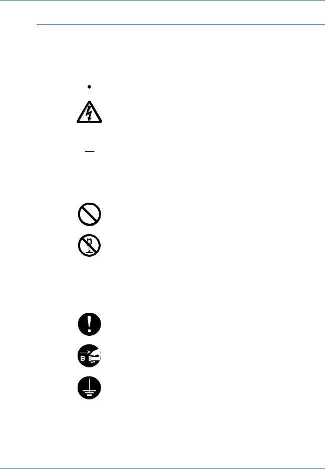
Правовая информация и информация по технике безопасности
Символы
Следующие символы обозначают, что в соответствующем разделе содержатся предупреждения по технике безопасности. Знаки внутри символа призваны привлечь внимание пользователя.
 … [Общее предупреждение]
…[Предупреждение об опасности поражения электрическим током]
 … [Предупреждение о сильном нагревании]
Следующие символы обозначают, что в соответствующие разделы включена информация о запрещенных действиях. Внутри символа приводится условное обозначение запрещенного действия.
… [Предупреждении о запрещенном действии]
… [Разборка запрещена]
Следующие символы обозначают, что в соответствующие разделы включена информация о действиях, подлежащих обязательному выполнению. Внутри символа приводится условное обозначение обязательного действия.
… [Предупреждение об обязательном действии]
… [Выньте шнур питания из розетки]
… [Подключайте аппарат только к заземленной розетке]
В случае, если предупреждения по технике безопасности в данном руководстве напечатаны неразборчиво, или в случае утраты самого руководства, обратитесь к представителю сервисной службы и
закажите новое руководство (за отдельную плату).
|
Основное руководство по эксплуатации |
v |

Правовая информация и информация по технике безопасности
Этикетки с предостережением
 Этикетки с предостережением
В целях безопасности на следущие компоненты аппарата наклеены этикетки с предостережениями. Выполняя процедуры устранения застревания бумаги или замены тонера будьте осторожны!
Не допускайте возгорания и помните об опасности поражения электрическим током.
|
Этикетка 2 |
Этикетка 3 |
||||||||||||||||||||||||||||||||||
|
Высокая температура. |
Не пытайтесь поджигать картридж с |
||||||||||||||||||||||||||||||||||
|
Во избежание ожогов не |
тонером. Искры от пламени могут |
||||||||||||||||||||||||||||||||||
|
дотрагивайтесь до компонентов |
стать причиной ожогов. |
||||||||||||||||||||||||||||||||||
|
этого отсека аппарата. |
|||||||||||||||||||||||||||||||||||
Этикетка 1 
Высокая температура. Во избежание ожогов не дотрагивайтесь до компонентов этого отсека аппарата.
Этикетка 4 
Не пытайтесь поджигать бункер отработанного тонера. Искры от пламени могут стать причиной ожогов.
ПРИМЕЧАНИЕ: Не удаляйте эти этикетки.
|
vi |
Основное руководство по эксплуатации |
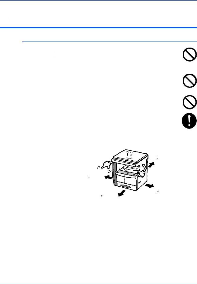
Правовая информация и информация по технике безопасности
Меры предосторожности при установке
 Меры предосторожности при установке
Окружающая среда
 ВНИМАНИЕ: Не устанавливайте аппарат на неустойчивой или неровной поверхности. В противном
случае аппарат может перевернуться и упасть. Это может привести к травме пользователя или повреждению аппарата.
Не устанавливайте аппарат во влажных, пыльных и сильно загрязненных местах. При попадании пыли или грязи на вилку шнура питания протрите ее во избежание возгорания или поражения электрическим током.
Во избежание возгорания не устанавливайте аппарат вблизи батарей, обогревателей и других источников тепла, а также рядом с открытым огнем.
Для предотвращения нагревания аппарата и обеспечения доступа внутрь аппарата при необходимости замены его компонентов и технического обслуживания, оставляйте достаточно свободного пространства так, как это показано на рисунке ниже. Для обеспечения оптимальной
вентиляции внутри аппарата оставляйте достаточно свободного пространства около его вентиляционных отверстий.
Сзади:
|
3 15/16« |
|||||||||
|
10 см |
|||||||||
|
Слева: |
|||||||||
|
11 13/16« |
|||||||||
|
30 см |
|||||||||
|
Справа: |
|||||||||
|
Спереди: |
11 13/16« |
||||||||
|
39 3/8« |
30 см |
||||||||
|
100 см |
|
Основное руководство по эксплуатации |
vii |

Правовая информация и информация по технике безопасности
Другие меры предосторожности
Неблагоприятные условия окружающей среды негативно сказываются на безопасной эксплуатации аппарата и его функционировании. Аппарат должен устанавливаться в помещении с кондиционером (рекомендуемая комнатная температура около 5090,5ЃF (10-32,5 ЃC), влажность около 15-80 %). Не следует устанавливать аппарат в следующих местах:
•вблизи окна или в местах, где он будет подвергаться воздействию прямого солнечного света;
•в местах, подверженных вибрации;
•в местах с резкими перепадами температуры;
•под направленными потоками горячего или холодного воздуха;
•в местах с плохой вентиляцией.
При перемещении данного аппарата после установки по полу, пол можно поцарапать.
При копировании происходит выделение небольшого количества озона, что однако никак не может отрицательно сказаться на здоровье человека. Однако, если аппарат используется в течение длительного периода времени в помещении с плохой вентиляцией, или при изготовлении чрезвычайно большого количества копий, по помещению может распространиться неприятный запах. Для обеспечения оптимальных условий окружающей среды при копировании, рекомендуется хорошо проветрить помещение.
|
viii |
Основное руководство по эксплуатации |
![]()
Правовая информация и информация по технике безопасности
Энергоснабжение/заземление аппарата
ПРЕДУПРЕЖДЕНИЕ: Подключайтеаппараттолько к источнику питания с напряжением, соответствующим напряжениюаппарата. Неподключайтенесколькоустройств в одну розетку. Это может привести к возгоранию или поражению электрическим током.
ПРЕДУПРЕЖДЕНИЕ: Надежно вставьте шнур питания в розетку. Контакт металлических предметов со штырьками вилки шнура питания может привести к возгоранию или поражению электрическим током.
ПРЕДУПРЕЖДЕНИЕ: Во избежание возгорания или поражения электрическим током в случае короткого замыкания, подключайте аппарат только к заземленной розетке. Если заземление невозможно, обратитесь к
представителю сервисной службы.
Другие меры предосторожности
Шнур питания аппарата следует подключать к ближайшей сетевой розетке.
Шнур питания используется также для отключения аппарата от сети. Проверьте, что сетевая розетка находится как можно ближе к аппарату и легко доступна.
Меры предосторожности при обращении с пластиковыми мешками
ПРЕДУПРЕЖДЕНИЕ: Храните пластиковые мешки, используемые в аппарате, в недоступном для детей месте. Пластик может попасть в нос и рот и привести к удушью.
|
Основное руководство по эксплуатации |
ix |
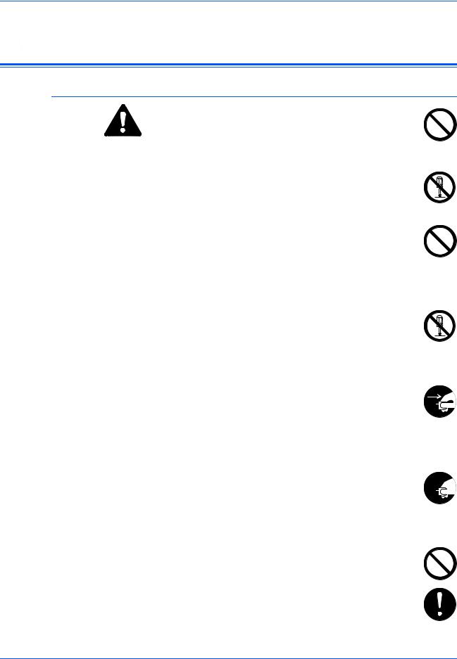
Правовая информация и информация по технике безопасности
Меры предосторожности при эксплуатации
 Меры предосторожности при эксплуатации
Меры предосторожности при эксплуатации аппарата
ПРЕДУПРЕЖДЕНИЕ: Не ставьте на аппарат и рядом с ним металлические предметы и сосуды с водой (вазы с цветами, цветочные горшки, чашки и т.д.). Падение этих предметов может привести к возгоранию или поражению электрическим током.
ПРЕДУПРЕЖДЕНИЕ: Не открывайте никакие крышки аппарата, так как это может привести к поражению
электрическим током. Внутри аппарата высокое напряжение!
ПРЕДУПРЕЖДЕНИЕ: Старайтесь не повредить и не порвать шнур питания. Не пытайтесь починить поврежденный шнур. Не ставьте на шнур тяжелые предметы. Не тяните за шнур, не сгибайте и старайтесь не повреждать его.
Несоблюдение этих правил может привести к возгоранию или поражению электрическим током.
ПРЕДУПРЕЖДЕНИЕ: Ни в коем случае не пытайтесь отремонтировать или разобрать самостоятельно
самаппаратилиегокомпоненты, таккакэтоможетпривести к возгоранию, поражению электрическим током или повредить лазер. Воздействие лазерного излучения при его выходе опасно для зрения и может привести к слепоте.
ПРЕДУПРЕЖДЕНИЕ: В случае чрезмерного нагревания аппарата, появления дыма, неприятного запаха
или возникновения любых других нетипичных ситуаций, 


 возникает опасность возгорания или повреждения электрическим током. Немедленно выключите выключатель питания (), выньте вилку шнура питания из розетки, а затем свяжитесь с представителем сервисной службы.
ПРЕДУПРЕЖДЕНИЕ: При попадании каких-либо предметов (скрепок для бумаги, воды, других жидкостей и 
 т.д.) внутрь аппарата, немедленно выключите выключатель

 питания (). Затем, во избежание возгорания и поражения электрическим током, выньте шнур питания из сетевой розетки. Затем свяжитесь с представителем сервисной службы.
ПРЕДУПРЕЖДЕНИЕ: Не дотрагивайтесь до вилки шнура питания мокрыми руками, так как это может привести к поражению электрическим током.
ПРЕДУПРЕЖДЕНИЕ: Техническое обслуживание аппарата и замена его внутренних компонентов должны выполняться только представителем сервисной службы.
|
x |
Основное руководство по эксплуатации |
Правовая информация и информация по технике безопасности
ВНИМАНИЕ: Вынимая шнур питания из розетки, не тяните за него. Если сильно тянуть шнур, можно порвать провода внутри шнура, что приведет к возгоранию или поражению электрическим током. (Вынимая шнур из розетки, держите его за вилку).
ВНИМАНИЕ: При перемещении аппарата всегда вынимайте шнур питания из розетки. При повреждении шнура питания может возникнуть опасность возгорания или поражения электрическим током.
Если аппарат не используется в течение короткого времени (ночью), выключайте выключатель питания (). Если аппарат не будет использоваться в течение более продолжительного периода (праздники, каникулы и т.д.), в целях безопасности выньте шнур питания из розетки.
Поднимая аппарат, держите его только за специально предназначенные для этого компоненты.
В целях безопасности перед очисткой аппарата всегда вынимайте шнур питания из сетевой розетки.
Скопление пыли внутри аппарата может привести к возгоранию и другим проблемам. Поэтому, по вопросам очистки внутренних компонентов аппарата, рекомендуем обратиться к представителю сервисной службы. Очистку внутренних компонентов рекомендуется проводить перед наступлением влажного времени года. По вопросам стоимости
процедур очистки внутренних компонентов аппарата обращайтесь к представителю сервисной службы.
Другие меры предосторожности
Не ставьте на аппарат тяжелые предметы. Это может повредить его.
Не открывайте верхнюю переднюю крышку, не выключайте выключатель питания и не вынимайте шнур питания из розетки во время копирования.
При необходимости перемещения или подъема аппарата свяжитесь с представителем сервисной службы.
Не дотрагивайтесь до электрических деталей (разъемов и печатных плат) аппарата, так как они могут быть повреждены за счет воздействия статического электричества.
Не выполняйте никаких операций, не описанных в данном руководстве.
ВНИМАНИЕ: Выполнение процедур управления, настройки и эксплуатации аппарата, отличных от изложенных в данном руководстве, может привести к опасному выходу радиоизлучения.
Не смотрите прямо на световой пучок лампы сканирования, так как это вредно для глаз.
|
Основное руководство по эксплуатации |
xi |
Правовая информация и информация по технике безопасности
Меры предосторожности при обращении с горючими материалами
ВНИМАНИЕ: Не пытайтесь поджигать контейнер с тонером или сосуд для отработанного тонера. Искры от пламени могут стать причиной ожогов.
Храните контейнер с тонером и сосуд для отработанного тонера в недоступном для детей месте.
В случае выливания тонера из контейнера или из сосуда для отработанного тонера не вдыхайте и не глотайте его, а также не допускайте попадания на кожу.
Есливывсе-такивдохнулитонер, выйдитенасвежийвоздух и тщательно прополощите горло большим количеством воды. При появлении кашля обратитесь к врачу.
Если вы проглотили тонер, прополоскайте рот водой и выпейте 1-2 чашкиводы, чтобыпромытьжелудок. Принеобходимостиобратитесь к врачу.
При попадании тонера в глаза тщательно промойте их водой. При продолжительном дискомфорте в глазах обратитесь к врачу.
При попадании тонера на кожу помойте ее водой с мылом.
Не пытайтесь открыть контейнер или сосуд для отработанного тонера силой.
Другие меры предосторожности
После использования, утилизация контейнера с тонером и сосуда для отработанного тонера должна выполняться в соответствии с федеральными, государственными и местными правилами и нормативными стандартами.
Все горючие материалы должны храниться в прохладном темном месте.
Если аппарат не будет использоваться в течение длительного периода, выньте бумагу из кассеты или лотка мульти-байпаса,
положите ее обратно в упаковку и запечатайте.
|
xii |
Основное руководство по эксплуатации |
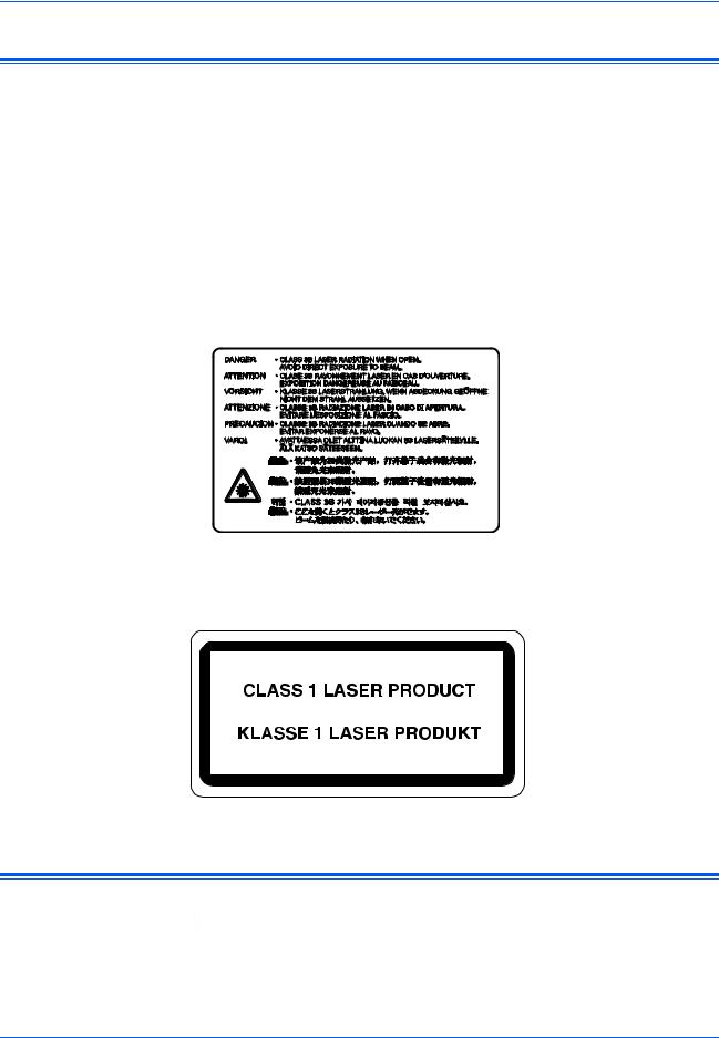
Правовая информация и информация по технике безопасности
Меры безопасности при работе с лазером
азерное излучение опасно для организма человека. Поэтому лазерное излучение, создаваемое внутри аппарата, герметично закрыто защитным кожухом и наружной крышкой. При правильной эксплуатации аппарата пользователем излучение не проникает за пределы его корпуса.
Настоящий аппарат классифицирован как лазерное изделие класса 1 в соответствии со стандартом IEC 60825.
Внимание: Выполнение процедур, отличных от изложенных в данном руководстве, может привести к опасному воздействию лазерного излучения.
Эти наклейки прикреплены на блок лазерного сканера внутри аппарата и находятся вне зоны доступа пользователя.
Наклейка, представленная на рисунке, прикреплена на правой стороне аппарата.
Отключение питания
 ВНИМАНИЕ: Аппарат считается полностью отключенным от сети только при изъятии вилки шнура питания из сетевой розетки!
  Другиевыключателинааппаратеявляютсятолькофункциональными выключателями и не предназначены для полного отключения аппарата от источника питания.
|
Основное руководство по эксплуатации |
xiii |

Правовая информация и информация по технике безопасности
ACHTUNG: Der Netzstecker ist die Hauptisoliervorrichtung! Die anderen Schalter auf dem Gerät sind nur Funktionsschalter und können nicht verwendet werden, um den Stromfluß im Gerät zu unterbrechen.
Декларация соответствия ЕС
ДЕКЛАРАЦИЯ СООТВЕТСТВИЯ СТАНДАРТАМ
2004/108/EC, 2006/95/EEC, 93/68/EEC и 1999/5/EC
Со всей единоличной ответственностью заявляем, что изделие, к которому относится данная декларация, полностью соответствует следующим стандартам.
EN55024
EN55022 Class B
EN61000-3-2
EN61000-3-3
EN60950-1
EN60825-1
EN300 330-1
EN300 330-2
|
xiv |
Основное руководство по эксплуатации |

Введение
Pуководство по эксплуатации включает следующие
главы:
•1 Компоненты аппарата
Названия компонентов аппаратов и основные функции.
•2 Подготовка
Инструкции по загрузке бумаги и подключению аппарата.
•3 Основные операции
Описание простейших процедур копирования и печати.
•4 Дополнительное оборудование
Описание предлагаемого дополнительного оборудования.
•5 Уход и обслуживание
Описание процедур технического обслуживания и заполнения тонера.
•6 Возможные неисправности
Описание процедур по устранению неисправностей (сообщения об ошибках или застревание бумаги).
•Приложение
Технические характеристики аппарата.
|
Основное руководство по эксплуатации |
xv |

Введение
Условные обозначения
В руководстве использованы следующие условные обозначения.
|
Условное |
Описание |
Пример |
||
|
обозначение |
||||
|
Курсив |
Используется для выделения |
Откройте лоток мульти-байпаса. |
||
|
ключевого слова, фразы или |
||||
|
сообщения. Кроме того, |
||||
|
курсивомвыделеныссылкина |
||||
|
другие руководства и |
||||
|
документы. |
||||
|
Полужирный |
Используется для выделения |
Нажмите [Ввод]. |
||
|
шрифт в |
выбранного функционального |
|||
|
квадратных |
режима или кнопки. |
|||
|
скобках |
||||
|
Примечания |
Предоставляет |
|||
|
ПРИМЕЧАНИЕ: Для обеспечения |
||||
|
дополнительную полезную |
||||
|
информацию о функции или |
наилучшего качества копирования эту |
|||
|
процедуру рекомендуется выполнять |
||||
|
режиме. |
||||
|
ежемесячно. |
||||
|
Важная |
Используется для |
ВАЖНАЯ ИНФОРМАЦИЯ: Ни в коем |
||
|
информация |
предоставления важной |
случае не используйте для очистки |
||
|
информации. |
стеклянной щели подачи воду, |
|||
|
растворитель и другие органические |
||||
|
растворы. |
||||
|
Внимание |
Призвано обратить внимание |
ВНИМАНИЕ: В целях |
||
|
пользователя на опасность |
безопасности перед очисткой |
|||
|
механического повреждения |
аппарата всегда вынимайте шнур |
|||
|
аппарата в результате |
питания из сетевой розетки. |
|||
|
совершения какого-либо |
||||
|
действия. |
||||
|
Предупреждение |
Призвано обратить внимание |
ПРЕДУПРЕЖДЕНИЕ: Отсек |
||
|
пользователя на опасность |
зарядника находится под высоким |
|||
|
получения травмы |
напряжением. |
|||
|
сотрудником. |
||||
Системы измерений
Данные в этом руководстве приводятся в двух системах измерений — американской (английской) и европейской (метрической). Данные на экранах и сообщениях, приведенных в руководстве в качестве примеров, указаны в дюймах. При использовании версии для метрической системы измерений, см. сообщения на вашем аппарате.
|
xvi |
Основное руководство по эксплуатации |

Содержание
Правовая информация и информация по технике безопасности
Правовая информация . . . . . . . . . . . . . . . . . . . . . . . . . . . . . . . . . . . . . . . . . . . . . . . . . . . . . . . . ii Программа Energy Star . . . . . . . . . . . . . . . . . . . . . . . . . . . . . . . . . . . . . . . . . . . . . . . . . . . . . . . . iii
Условные обозначения по технике безопасности . . . . . . . . . . . . . . . . . . . . . . . . . . . . . . . . . . .iv
Этикетки с предостережением . . . . . . . . . . . . . . . . . . . . . . . . . . . . . . . . . . . . . . . . . . . . . . . . . .vi Меры предосторожности при установке . . . . . . . . . . . . . . . . . . . . . . . . . . . . . . . . . . . . . . . . . vii Энергоснабжение/заземление аппарата . . . . . . . . . . . . . . . . . . . . . . . . . . . . . . . . . . . . . . . . . .ix Меры предосторожности при эксплуатации . . . . . . . . . . . . . . . . . . . . . . . . . . . . . . . . . . . . . . . x Меры безопасности при работе с лазером. . . . . . . . . . . . . . . . . . . . . . . . . . . . . . . . . . . . . . . . xiii Отключение питания . . . . . . . . . . . . . . . . . . . . . . . . . . . . . . . . . . . . . . . . . . . . . . . . . . . . . . . . . xiii Декларация соответствия ЕС . . . . . . . . . . . . . . . . . . . . . . . . . . . . . . . . . . . . . . . . . . . . . . . . . . xiv
Введение
Условные обозначения . . . . . . . . . . . . . . . . . . . . . . . . . . . . . . . . . . . . . . . . . . . . . . . . . . . . . . . xvi
1 Компоненты аппарата
Основной корпус . . . . . . . . . . . . . . . . . . . . . . . . . . . . . . . . . . . . . . . . . . . . . . . . . . . . . . . . . . . . 1-2 Панель управления. . . . . . . . . . . . . . . . . . . . . . . . . . . . . . . . . . . . . . . . . . . . . . . . . . . . . . . . . . 1-5 Дисплей сообщений . . . . . . . . . . . . . . . . . . . . . . . . . . . . . . . . . . . . . . . . . . . . . . . . . . . . . . . . . 1-7
2 Подготовка
Загрузка бумаги. . . . . . . . . . . . . . . . . . . . . . . . . . . . . . . . . . . . . . . . . . . . . . . . . . . . . . . . . . . . . 2-2 Подключение . . . . . . . . . . . . . . . . . . . . . . . . . . . . . . . . . . . . . . . . . . . . . . . . . . . . . . . . . . . . . . 2-11 Включение питания. . . . . . . . . . . . . . . . . . . . . . . . . . . . . . . . . . . . . . . . . . . . . . . . . . . . . . . . . 2-13 Сетевые настройки . . . . . . . . . . . . . . . . . . . . . . . . . . . . . . . . . . . . . . . . . . . . . . . . . . . . . . . . . 2-14 Установка даты и времени . . . . . . . . . . . . . . . . . . . . . . . . . . . . . . . . . . . . . . . . . . . . . . . . . . . 2-17 Настройка языка . . . . . . . . . . . . . . . . . . . . . . . . . . . . . . . . . . . . . . . . . . . . . . . . . . . . . . . . . . . 2-19
3 Основные операции
Основная процедура копирования. . . . . . . . . . . . . . . . . . . . . . . . . . . . . . . . . . . . . . . . . . . . . . 3-2
Выполнение копий с использованием масштабирования . . . . . . . . . . . . . . . . . . . . . . . . . . . 3-5
Режим двусторонней печати. . . . . . . . . . . . . . . . . . . . . . . . . . . . . . . . . . . . . . . . . . . . . . . . . . . 3-9 Копирование с разбором по копиям . . . . . . . . . . . . . . . . . . . . . . . . . . . . . . . . . . . . . . . . . . . 3-13 Совмещенное копирование . . . . . . . . . . . . . . . . . . . . . . . . . . . . . . . . . . . . . . . . . . . . . . . . . . 3-14 Режим прерывания . . . . . . . . . . . . . . . . . . . . . . . . . . . . . . . . . . . . . . . . . . . . . . . . . . . . . . . . . 3-18 Энергосберегающий режим . . . . . . . . . . . . . . . . . . . . . . . . . . . . . . . . . . . . . . . . . . . . . . . . . . 3-21 Автоматический неактивный режим . . . . . . . . . . . . . . . . . . . . . . . . . . . . . . . . . . . . . . . . . . . 3-22 Основная процедура печати. . . . . . . . . . . . . . . . . . . . . . . . . . . . . . . . . . . . . . . . . . . . . . . . . . 3-23
4 Дополнительное оборудование
Краткий обзор дополнительного оборудования . . . . . . . . . . . . . . . . . . . . . . . . . . . . . . . . . . . 4-2
Обработчик документов . . . . . . . . . . . . . . . . . . . . . . . . . . . . . . . . . . . . . . . . . . . . . . . . . . . . . . 4-3
|
Основное руководство по эксплуатации |
xvii |

Содержание
Погрузчик бумаги. . . . . . . . . . . . . . . . . . . . . . . . . . . . . . . . . . . . . . . . . . . . . . . . . . . . . . . . . . . . 4-7 Устройство двусторонней печати . . . . . . . . . . . . . . . . . . . . . . . . . . . . . . . . . . . . . . . . . . . . . . 4-8 Финишер . . . . . . . . . . . . . . . . . . . . . . . . . . . . . . . . . . . . . . . . . . . . . . . . . . . . . . . . . . . . . . . . . . 4-8 Разделитель заданий . . . . . . . . . . . . . . . . . . . . . . . . . . . . . . . . . . . . . . . . . . . . . . . . . . . . . . . 4-12 Ключ-счетчик . . . . . . . . . . . . . . . . . . . . . . . . . . . . . . . . . . . . . . . . . . . . . . . . . . . . . . . . . . . . . . 4-13 Комплект для приема/передачи факса . . . . . . . . . . . . . . . . . . . . . . . . . . . . . . . . . . . . . . . . . 4-14 Комплект для сетевого сканера. . . . . . . . . . . . . . . . . . . . . . . . . . . . . . . . . . . . . . . . . . . . . . . 4-14 Карта памяти (CompactFlash). . . . . . . . . . . . . . . . . . . . . . . . . . . . . . . . . . . . . . . . . . . . . . . . . 4-14 Сетевая интерфейсная плата (IB-23) . . . . . . . . . . . . . . . . . . . . . . . . . . . . . . . . . . . . . . . . . 4-14 Жесткий диск . . . . . . . . . . . . . . . . . . . . . . . . . . . . . . . . . . . . . . . . . . . . . . . . . . . . . . . . . . . . . . 4-15 Расширенный модуль памяти . . . . . . . . . . . . . . . . . . . . . . . . . . . . . . . . . . . . . . . . . . . . . . . . 4-15
5 Уход и обслуживание
Очистка аппарата . . . . . . . . . . . . . . . . . . . . . . . . . . . . . . . . . . . . . . . . . . . . . . . . . . . . . . . . . . . 5-2
Замена контейнера с тонером и сосуда для отработанного тонера. . . . . . . . . . . . . . . . . . . 5-5
6 Возможные неисправности
Устранение неисправностей. . . . . . . . . . . . . . . . . . . . . . . . . . . . . . . . . . . . . . . . . . . . . . . . . . . 6-2
Сообщения об ошибках и процедуры по их устранению. . . . . . . . . . . . . . . . . . . . . . . . . . . . 6-6
Устранение застревания бумаги . . . . . . . . . . . . . . . . . . . . . . . . . . . . . . . . . . . . . . . . . . . . . . 6-12
Приложение
Технические характеристики . . . . . . . . . . . . . . . . . . . . . . . . . . . . . . . . . . . . . . . . . Приложение-2
|
xviii |
Основное руководство по эксплуатации |
![]()
1 Компоненты аппарата
В настоящей главе рассматриваются следующие темы:
|
• |
Основной корпус………………………………………………… |
1-2 |
|
• |
Панель управления ……………………………………………. |
1-5 |
|
• |
Дисплей сообщений…………………………………………… |
1-7 |
|
Основное руководство по эксплуатации |
1-1 |
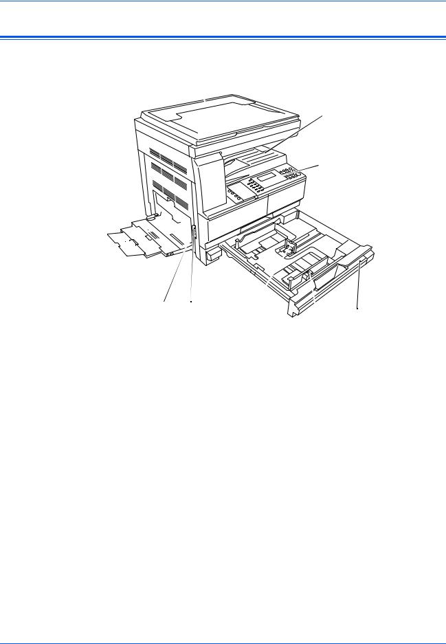
Компоненты аппарата
Основной корпус
1
2
 3
3
8


 9
9 


|
10 |
7 |
6 |
5 |
4 |
1Крышка стекла оригинала
2Выходной лоток
3Панель управления
4Кассета
5Регулятор ширины бумаги
6Регулятор длины бумаги
7Ручка левой крышки
8Лоток мульти-байпаса
9Удлинитель лотка мульти-байпаса
10Внутренние направляющие
|
1-2 |
Основное руководство по эксплуатации |
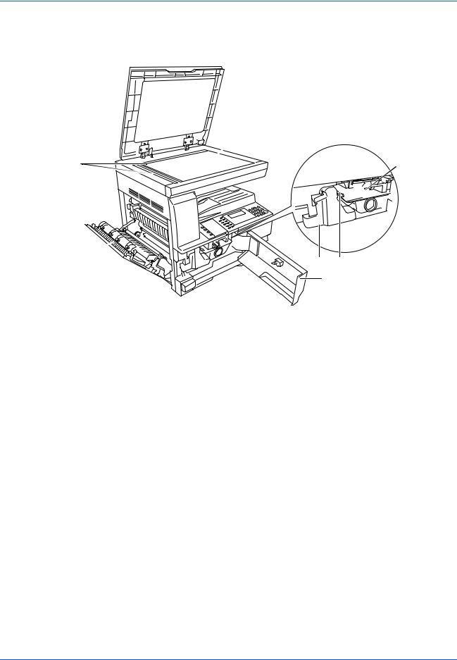
Компонентыаппарата
11


 16
16
11Стекло оригинала
12Индикаторы формата оригинала
13Левая крышка
14Сосуд для отработанного тонера
15Освобождающий рычаг контейнера с тонером
16Контейнер с тонером
17Стержень для очистки зарядника
18Передняя крышка
|
Основное руководство по эксплуатации |
1-3 |
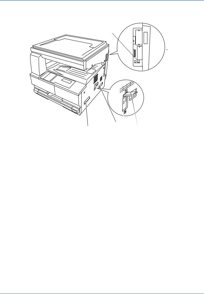
Компоненты аппарата
23
 24
24  22
22
|
21 |
21 |
20 |
|
|
19 |
|||
19Основной выключатель питания
20Крышка основного выключателя питания
21Ручки для транспортировки
22Разъем для подключения к сетевому интерфейсу
23Разъем для подключения к USB интерфейсу
24Слот для карты памяти
|
1-4 |
Основное руководство по эксплуатации |
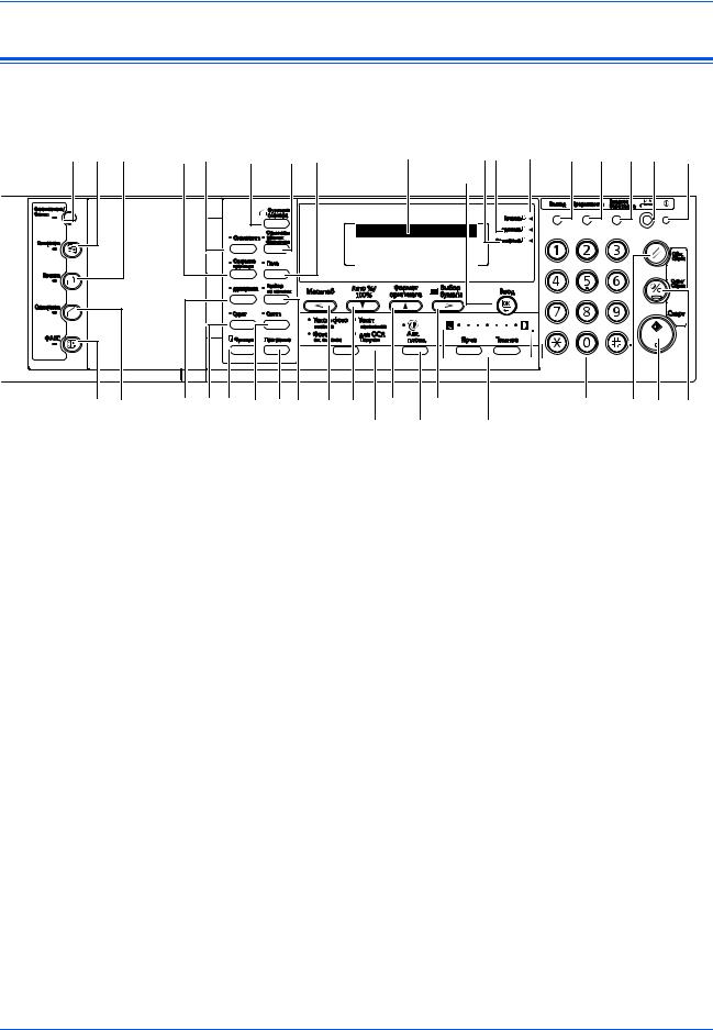
Компонентыаппарата
Панель управления
|
7 |
6 |
11 |
12 |
13 |
25 |
28 27 |
26 |
29 |
30 |
31 |
32 |
37 |
|||
|
21 |
|||||||||||||||
|
Готов к копированию. |
|||||||||||||||
|
100% |
Авто |
Авто |
1 |
||||||||||||
|
8 |
9 |
10 |
15 16 14 |
17 |
18 |
19 |
20 |
33 |
34 |
36 |
35 |
||||
|
22 |
23 |
24 |
1Кнопка и индикатор Cистемное меню/Cчетчик
2Кнопка и индикатор Kопировать
3Кнопка и индикатор Печатать
4Кнопка и индикатор Сканировать
5Кнопка и индикатор ФАКС
6Кнопка и индикатор Совместить
7Кнопка и индикатор Стирание границы
8Кнопка и индикатор Двусторонняя
9Кнопка и индикатор Сдвиг
10Кнопка Функция
11Кнопка Функция сканера
12Кнопка и индикатор Оригиналы разных форматов
13Кнопка и индикатор Поле
14Кнопка и индикатор Разбор по копиям
15Кнопка и индикатор Сшить
16Кнопка Программа
17Кнопка Масштаб/< Кнопка
18Кнопка Авто%/100% /
19Кнопка Формат Ввод оригинала /
20Кнопка Выбор бумаги />
21Кнопка Ввод
|
Основное руководство по эксплуатации |
1-5 |

Компоненты аппарата
|
22 |
Кнопка выбора режима качества изображения |
|
23 |
Кнопка Авт. плотн. |
|
24 |
Кнопка Ярче / Кнопка Темнее / Дисплей экспозиций |
|
25 |
Дисплей сообщений |
|
26 |
Индикатор Готово (зеленый) |
|
27 |
Индикатор данные (зеленый) |
|
28 |
Индикатор Внимание (красный) |
|
29 |
Кнопка Выход |
|
30 |
Кнопка и индикатор Прерывание |
|
31 |
Кнопка и индикатор Энергосбережение |
|
32 |
Кнопка и индикатор Питание |
|
33 |
Цифровые кнопки |
|
34 |
Кнопка Общ. Сброс |
|
35 |
Кнопка Стоп/Сброс |
|
36 |
Кнопка и индикатор Старт |
|
37 |
Индикатор электропитания |
|
ПРИМЕЧАНИЕ: • |
Первоначальный режим (состояние аппарата на момент |
|
окончания прогрева или при нажатии клавиши Общ.Сброс). В |
|
|
заводских настройках по умолчанию бумага одинакового с |
|
|
оригиналом размера выбирается автоматически (режим |
|
|
автоматического выбора бумаги), коэффициент |
|
|
масштабирования при копировании установлен на 100 %, |
|
|
количество выполняемых копий установлено на 1, а качество |
|
|
изображения установлено в режим Текст + фото. |
|
|
• |
Настройки для первоначального режима можно изменить с |
|
помощью процедуры настроек, используемых по умолчанию. |
|
|
Сюда входят изменение кассеты, выбираемой в первоначальном |
|
|
режиме, режим качества изображения и экспозиции |
|
|
(автоматический режим экспозиции). |
Функция автосброса
По истечении указанного времени после прекращения копирования (от 10 до 270 секунд) в аппарате восстанавливаются настройки, действовавшие после прогрева. Копии могут выполняться непрерывно с использованием одинаковых настроек (режим копирования , количество копий и режим экспозиции), если следующая серия копирования запускается до активации функции автосброса..
|
1-6 |
Основное руководство по эксплуатации |

Компонентыаппарата
Дисплей сообщений
На дисплее сообщений отображается операционный режим аппарата.
Основной экран копирования
При нажатии кнопки Kопировать появляется следующий экран.
|
Готов к копированию. |
4 |
|||||||||
|
Авто |
||||||||||
|
100% |
Авто |
1 |
6 |
|||||||
2 5
|
Номер |
Описание |
|
|
ссылки |
||
|
1 |
Обозначает текущее состояние аппарата. |
|
|
2 |
Отображается при автоматическом выборе формата |
|
|
оригинала. |
||
|
3 |
Отображает коэффициент увеличения при копировании. |
|
|
4 |
Отображается, если выбран режим автоматического |
|
|
выбора бумаги. |
||
|
5 |
Отображает формат оригинала, формат бумаги и |
|
|
выбранную кассету. |
||
|
6 |
Выбранное число копий. |
|
|
Основное руководство по эксплуатации |
1-7 |

Компоненты аппарата
Основной экран принтера
При нажатии кнопки Печатать появляется следующий экран:
|
1 |
Готово |
||
|
2 |
GO |
||
3ОТМЕНА
4МЕНЮ
|
Номер |
Описание |
|
|
ссылки |
||
|
1 |
Отображает текущее состояние аппарата. |
|
|
2 |
Выбирается для переключения между режимами онлайн |
|
|
и оффлайн, для печати/возобновления печати, для |
||
|
исправления ошибки и для отмены текущей |
||
|
обрабатываемой страницы и печати новой страницы. |
||
|
3 |
Выбирается для остановки процесса печати. |
|
|
4 |
Выбирается для корректировки сетевых настроек. |
|
|
Более подробную информацию см. Сетевые настройки, |
||
|
ñòð. 2-14. |
||
ПРИМЕЧАНИЕ: Следующую процедуру можно также использовать для изменения настроек функций принтера по умолчанию.
1 Нажмите клавишу «Системное меню / счетчик«.
|
2 Нажмите клавишу или |
||||
|
Системное меню / счетчик: |
||||
|
клавишу для выбора «По |
||||
|
Копирование по умолч. |
||||
|
умолчанию». |
||||
|
Машина по умолчанию |
||||
|
3 Нажмите клавишу «Ввод». |
Принтер по умолчанию |
|||
|
Отображается экран, |
||||
|
отображаемый при выборе «МЕНЮ» на начальном экране |
||||
|
принтера. |
|
1-8 |
Основное руководство по эксплуатации |

2 Подготовка
В настоящей главе рассматриваются следующие темы:
|
• |
Загрузка бумаги…………………………………………………. |
2-2 |
|
• |
Подключение…………………………………………………….. |
2-11 |
|
• |
Включение питания………………………………………….. |
2-13 |
|
• |
Сетевые настройки…………………………………………… |
2-14 |
|
• Установка даты и времени………………………………… |
2-17 |
|
|
• |
Настройка языка………………………………………………. |
2-19 |
|
Основное руководство по эксплуатации |
2-1 |

Подготовка
Загрузка бумаги
Бумага и другие материалы для печати, копирования, сканирования загружаются в кассету или в универсальный лоток.
ПРИМЕЧАНИЕ: Более подробную информацию об используемых типах бумаги и материалов см. Приложение, Advanced Operation Guide.
Подготовка бумаги
Выньте бумагу из упаковки и разверните листы веером, чтобы разделить их перед загрузкой.
При использовании сложенной или помятой бумаги, распрямитееепередзагрузкой. В противном случае такая бумага может застрять в аппарате.
ВАЖНАЯ ИНФОРМАЦИЯ: Убедитесь, что листы не скреплены, а зажимы сняты.
При загрузке бумаги в кассету она кладется лицевой стороной вверх к упаковке, а при загрузке на универсальный лоток лицевой стороной вниз.
При высокой температуре и влажности, чтобы бумага не отсыревала, ее не рекомендуется вынимать из упаковки. Загрузив бумагу в кассету или универсальный лоток, запечатайте оставшуюся в упаковке бумагу. Если аппарат не будет использоваться в течение длительного времени, выньте всю бумагу из кассеты и универсальный лоток, положите ее в упаковку и запечатайте.
Загрузка бумаги в кассету
В кассету можно загружать стандартную бумагу (80 г/кв.м), плотную бумагу (90 — 105 г/кв.м), вторичную или цветную бумагу. В каждую кассету за один раз можно загрузить до 300 листов стандартной бумаги (80 г/кв.м).
Разрешаетсязагружатьбумагуследующихформатов: A3, B4, A4, A4R, B5, B5R, A5R, Folio, 11 х 17″ (Ledger), 8 1/2 х 14″ (Legal), 11 х 8 1/2«,
8 1/2 х 11″ (Letter), 5 1/2 х 8 1/2» (Statement), 8 1/2 х 13″ (Oficio II), 8K, 16K.
ВАЖНАЯ ИНФОРМАЦИЯ: При загрузке в кассету бумага должна быть обращена стороной для печати вверх.
|
2-2 |
Основное руководство по эксплуатации |
![]()
|
Подготовка |
|
|
1 |
Полностью выньте кассету из |
|
аппарата. |
|
|
ВАЖНАЯ ИНФОРМАЦИЯ: |
|
|
Вынимая кассету из аппарата, |
|
|
придерживайте ее, чтобы |
|
|
случайно не уронить. |
|
|
ПРИМЕЧАНИЕ: За один раз вынимайте только одну кассету. |
|
2 |
Надавите на основание |
|
кассеты. |
|
3 |
С помощью регулятора |
|
ширины бумаги установите |
направляющие ширины в соответствии с требуемым форматом бумаги.
ПРИМЕЧАНИЕ: Форматы бумаги нанесены на кассете. Убедитесь, что направля ющие ширины касаются бумаги. При наличии зазора между направля ющими и бумагой отрегулируйте направля ющие ширины повторно.
|
4 |
С помощью регулятора |
|
длины бумаги установите |
направляющую длины в соответствии с требуемым форматом бумаги.
|
Основное руководство по эксплуатации |
2-3 |

Подготовка
При загрузке бумаги формата
A3 или 11 х 17″ (Ledger)
переместите регулятор длины бумаги вправо до упора и надавите на него вниз так, как показано на рисунке.
|
ПРИМЕЧАНИЕ: Форматы бумаги нанесены на кассете. |
||
|
5 |
Загрузите бумагу в кассету, |
|
|
кромкадолжнабытьвыровнена |
||
|
с направляющей длины бумаги. |
||
|
ВАЖНАЯ ИНФОРМАЦИЯ: |
||
|
Перед загрузкой бумаги во |
||
|
избежание ее неправильной |
||
|
подачи и застревания следует |
||
|
отрегулировать направляющие |
||
|
длины и ширины бумаги. |
||
|
Проверьте, что бумага надежно без зазора зафиксирована между |
||
|
направляющими длины и ширины. Если направляющие установлены |
||
|
неправильно, на дисплее сообщений отображается неверный |
||
|
формат бумаги. |
||
|
Не загружайте больше |
Ограничительные |
|
|
бумаги, чем входит под |
||
|
метки |
||
|
ограничительные метки |
||
|
загрузкибумаги, нанесенныена |
||
|
направляющей ширины. |
||
|
Проверьте, что бумага лежит |
||
|
вверх той стороной, на которую |
||
|
будет выполняться или печать. |
||
|
Бумага не должна быть смята, |
||
|
6 |
согнута, порвана. |
|
|
Присоедините поставляемую |
||
|
этикетку таким образом, чтобы |
размер бумаги, установленный в кассете, можно было определить с передней стороны кассеты.
|
2-4 |
Основное руководство по эксплуатации |

|
Подготовка |
|
|
7 |
Вставьте кассету обратно в |
|
аппарат до упора. |
|
|
ВАЖНАЯ ИНФОРМАЦИЯ: Есл |
|
|
и аппарат не будет |
|
|
использоваться в течение |
|
|
длительного времени, |
|
|
извлеките бумагу из кассеты, |
|
|
поместите ее в пакет для |
|
|
хранения и запечатайте пакет |
|
|
во избежание увлажнения бумаги. |
Загрузка бумаги в универсальный лоток
Помимо стандартной и переработанной бумаги, можно использовать также специальную бумагу. Специальную бумагу следует обязательно устанавливать в универсальный лоток.
Можно установить до 100 листов стандартной (80 г/м) бумаги (25
листов A3, B4, Folio, 11х 17″ (Ledger), 8 1/2 х 14″ (Legal), 8 1/2 х 13″ (Oficio II) или 8K). Размеры бумаги, которые можно использовать: от
A3 до A6R, открытка, Folio, от 11 х 17″ (Ledger) до 5 1/2 х 8 1/2″ (Statement), 8K, 16K и 16KR.
В зависимости от типа и формата бумаги можно загружать следующее число листов:
|
Тип или формат |
Емкость |
|||
|
Стандартная бумага |
100 листов |
|||
|
Тонкая и плотная бумага |
50 |
листов (от 90 до 105 г/м) |
||
|
Hagaki |
15 |
листов |
||
|
Цветная бумага |
100 листов |
|||
|
КонвертDL, КонвертC5, Конверт#10 |
5 листов |
|||
|
(Коммерческий#10), Monarch, Youkei |
||||
|
4, Youkei 2 |
||||
|
1 Откройте универсальный лоток. |
||||
|
Основное руководство по эксплуатации |
2-5 |

Подготовка
Вытащите удлинитель универсального лотка соответственно формату бумаги.
|
2 |
Отрегулируйте внутренние |
|
направляющие в соответствии |
с шириной бумаги.
|
3 |
Положите бумагу вдоль |
|
внутренних направляющих и |
|
|
вдвиньте ее в лоток как можно |
|
|
дальше. |
|
|
Убедитесь, что внутренние |
|
|
направляющие выровнены по |
|
|
краю бумаги. |
|
|
ВАЖНАЯ ИНФОРМАЦИЯ: |
|
|
Перед загрузкой выпрямите |
|
|
открытки и плотную бумагу других видов, если она скручивается. |
|
|
Бумага, не соответствующая техническим требованиям может не |
|
|
подаваться в аппарат. |
Бумагу следует загружать в лоток непосредственно перед использованием и не оставлять ее в лотке в течение длительного времени.
Бумага должна загружаться в универсальный лоток вниз той стороной, на которую будет выполняться копирование или печать. Проверьте бумагу на отсутствие складок и т. п. Складки на бумаге могут привести к замя тию бумаги.
|
2-6 |
Основное руководство по эксплуатации |

|
Подготовка |
|
Загрузка открыток или конвертов в универсальный лоток |
|
|
1 |
При загрузке открытки или |
|
конверта откройте фиксатор |
|
|
бумаги, показанный на рисунке. |
|
|
При работе с конвертами |
|
|
альбомного формата закройте |
|
|
клапан. Загрузите конверт |
|
|
вдоль направляющих ширины |
|
|
до упора, стороной для печати |
|
|
вниз с повернутым к вам |
|
|
клапаном. Для конвертов |
|
|
портретной ориентации необходимо закрыть клапан. Загрузите |
|
|
конверт вдоль направляющих ширины до упора стороной для печати |
|
|
вниз, чтобы край с клапаном был повернут к прорези. |
|
Можно загрузить до пяти конвертов |
|
Закройте клапан. |
ВАЖНАЯ ИНФОРМАЦИЯ: Загрузка конверта (ориентация и сторона загрузки) отличается для разных типов конвертов. При неправильной загрузке конверта печать может быть выполнена в неверном направлении или на стороне, не предназначенной для печати.
|
Основное руководство по эксплуатации |
2-7 |

Подготовка
Формат и тип бумаги для универсальный лоток
Перед использованием универсальный лоток установите формат и вид бумаги, следуя приведенным ниже инструкциям.
Размер бумаги
Для универсальный лоток предлагаются следующие опции:
•Обычный размер бумаги — стандартные форматы бумаги, которые можно выбрать из меню Размер бумаги байпаса.
•Другой обычный размер — данная опция предназначена для дополнительных обычных форматов бумаги.
•Введите размер — данная опция используется для ввода формата пользователем, если формат загружаемой бумаги не отображен на дисплее.
Обычный размер бумаги:
Доступны следующие обычные форматы бумаги:
•A3, B4, A4R, A4, B5R, B5, A5R, B6R, A6R, 8 1/2 х 11″ (Letter), 11 х 8 1/2«, Folio.
1 Нажмите кнопку [Cистемное меню/Cчетчик].
|
2 |
Нажмите или , выберите |
|
Устан.универс.лотка и |
нажмите [Ввод].
Системное меню / счетчик: Конец Язык 

 Настр. универс. лотка
|
3 |
Нажмите или , выберите |
|||
|
Размер бумаги Ун.лоток: |
||||
|
Устан.универс.лотка и нажмите |
||||
|
Введите размеp |
||||
|
[Ввод]. |
||||
|
Появляется экран |
||||
|
Тип_универс._лотка. Выберите требуемый тип бумаги, следуя |
||||
|
инструкциям ñòð. 2-10. |
|
2-8 |
Основное руководство по эксплуатации |

Подготовка
Другой обычный размер:
Доступны следующие дополнительные обычные форматы бумаги:
•11 Ч 17″ (Ledger), 8 1/2 Ч 14″ (Legal), 8 1/2 Ч 13″ (Oficio II), 5 1/2 Ч 8 1/2″ (Statement), HAGAKI, Executive, ISO B5, Envelope DL, Envelope C5, Envelope C4, Comm. #10, Comm. #9, Comm. #6-3/4, Monarch, OufukuHagaki, YOUKEI 2, YOUKEI 4, 8K, 16KR, 16K
Нажмите кнопку [Cистемное меню/Cчетчик].
|
Нажмите или , |
|||
|
Системное меню / счетчик: |
|||
|
Устан.универс.лотка и нажмите |
|||
|
Конец |
|||
|
[Ввод]. |
|||
|
Язык |
|||
|
Настр. универс. лотка |
|||
|
3 |
Нажмите или , выберите |
|
Другой cтaнд. размер и |
нажмите [Ввод].
Размер бумаги Ун.лоток:  11×8 1/2
HAGAKI
Другой станд. размер 
|
4 |
Нажмите или , выберите |
||
|
Другой станд. размер: |
|||
|
требуемый формат бумаги и |
11×17 |
||
|
нажмите [Ввод]. |
8 1/2×14 |
||
|
Появляется экран |
8 1/2×13 |
||
|
Тип_универс._лотка. Выберите требуемый тип бумаги, следуя |
|||
|
инструкциям ñòð. 2-10. |
|
Основное руководство по эксплуатации |
2-9 |

Подготовка
Введите формат:
Нажмите кнопку [Cистемное меню/Cчетчик].
|
Нажмите или , выберите |
||
|
Системное меню / счетчик: |
||
|
Устан.универс.лотка и нажмите |
Конец |
|
|
[Ввод]. |
||
|
Язык |
||
|
Настр. универс. лотка |
||
|
3 |
Нажмите или , выберите |
|
Введите размер и нажмите |
|
|
[Ввод]. |
|
|
4 |
Нажмите < или > и выберите |
|
нужный вертикальный формат, |
|
|
от 98 — 297 мм с шагом 1 мм. |
|
|
Нажмите и выберите |
|
|
горизонтальный формат. |
|
|
5 |
Нажмите < или > и выберите |
|
нужный горизонтальный |
формат, от 148 до 432 мм с шагом 1 мм.
Размер бумаги Ун.лоток:
|
Универсальный размер |
||
|
* |
||
|
Введите размеp |
||
Введите размер:  98mm 297mm
Введите размер: 98mm 297mm
Нажмите [Ввод]. Появляется экран Тип_универс._лотка.
Выберите требуемый тип бумаги, следуя инструкциям ñòð. 2-10.
Тип бумаги
Разрешается загружать бумагу следующих типов:
•Обычная, пленки, надпечатанная, этикетки, гербовая, макулатурная, калька, черновая, бланк, цветная, перфорированная, конверт, карточки, плотная бумага, высококачественная, специальная 1(до 8).
|
1 |
Выбрав нужный формат |
|
бумаги, нажмите или и |
выберите нужный тип бумаги.
Нажмите [Ввод]. Появляется
Тип универс.лотка.
Тип бумаги Ун.лоток:
 * ОбычнаяПленки бумага Надпечатанная
|
2-10 |
Основное руководство по эксплуатации |

Подготовка
Подключение
Подключение к сети
|
Для подключения аппарата к сети используется сетевой кабель |
|
|
(10Base-T или 100Base-TX). |
|
|
1 |
Откройте крышку основного |
|
выключателя питания с правой |
|
|
стороны аппаратаи установите |
|
|
выключатель питания в |
|
|
выключенное положение (), |
|
|
затем выньте шнур питания из |
|
|
сетевой розетки. |
|
2 |
Вставьте сетевой кабель в |
|
разъем для подключения к |
сетевому интерфейсу с
правой стороны аппарата.
Другой конец сетевого кабеля вставьте в сетевое устройство (концентратор).
Запрограммируйте необходимые сетевые настройки. Более подробную информацию см. Сетевые настройки, ñòð. 2-14.
|
Основное руководство по эксплуатации |
2-11 |

Подготовка
Подсоединение кабеля USB
|
Для подключения аппарата к компьютеру напрямую используйте |
|
|
любой кабель USB. |
|
|
ВАЖНАЯ ИНФОРМАЦИЯ: Перед подключением кабеля принтера |
|
|
всегда выключайте питание аппарата () и вынимайте шнур питания |
|
|
из розетки. |
|
|
1 |
Проверьте, что питание компьютера выключено. |
|
Откройте крышку основного |
|
|
выключателя питания с правой |
|
|
стороны аппаратаи установите |
|
|
выключатель питания в |
|
|
выключенное положение (), |
|
|
затем выньте шнур питания из |
|
|
сетевой розетки. |
|
2 |
Подсоедините кабель принтера к разъему интерфейса USB, |
||
|
расположенному с правой стороны аппарата. |
|||
|
3 |
Подключите другой конец кабеля к разъему интерфейса USB на |
|
компьютере. |
Подключение питания
|
1 |
Вставьте шнур питания в разъем для подключения шнура питания с |
|
правой стороны аппарата. |
|
|
2 |
Другой конец шнура вставьте в сетевую розетку. |
|
2-12 |
Основное руководство по эксплуатации |
![]()
Подготовка
Включение питания
|
Откройте крышку основного |
|
выключателя питания с правой |
|
стороны аппаратаи установите |
|
выключатель питания во |
|
включенное положение ( | ). |
|
Аппарат начнет прогреваться. |
|
По окончании нагрева |
|
загорается зеленый индикатор |
|
Старт. |
|
Основное руководство по эксплуатации |
2-13 |
 Loading…
Access any files, from drivers to manuals, that you may need for your Kyocera product.

-
Drivers
-
Documents
-
Software
We have detected your Operating System:
System info will go here
There are currently no additional documents related to this category.
There are currently no additional documents related to this category.
There are currently no additional documents related to this category.
To download this file please first accept the terms and conditions
Before clicking on the “accept and continue” button to commence downloading the software (“Software”) or documentation (“Documentation”), you should carefully read the terms and conditions of this license agreement (“Agreement”). By clicking on the “accept and continue” button you are agreeing to be legally bound by the terms and conditions of this Agreement and agree to become a licensee. If you do not agree to all of the terms and conditions of this Agreement you should clicking on the “cancel” button and not download or use the Software and/or Documentation.
When you accept the terms and conditions of this Licence Agreement, Kyocera Document Solutions Europe BV (“Licensor”) shall immediately grant you (the «Licensee» meaning either an individual or a single entity) a limited, non-exclusive, non-transferrable licence to use the Software and/or the Documentation on the terms of the Agreement.
SOFTWARE
1 Use of Software
1.1 Licensor grants Licensee a license to use one copy of the Software on one or more computers connected to an original “KYOCERA” printer, copier or multifunctional device. Use means any permanent or temporary use of the Software and includes the storing, loading, installing, executing or displaying of the Software or the processing of any data contained therein. The Software may not be used on any other hardware unless such use is granted by a separate license agreement.
2 Intellectual Property Rights
2.1 All ownership and intellectual property rights in the Software and any derivative work(s) shall remain exclusively with the Licensor and/or its licensors.
Licensee acknowledges such ownership rights and will not take any action to jeopardise, limit or interfere in any manner with Licensor’s rights with respect to the Software. Furthermore, Licensee may not remove or alter any trademark, logo, copyright or other proprietary notices, legends, symbols or labels in the
Software without the prior written permission of Licensor. Any unauthorized deviation from this condition will result in automatic termination of the Agreement. Licensor reserves the right to take legal action for breach of this condition
3 Rights to copy Software
3.1 Licensee may only copy the Software where this is essential to usage. This includes the installation and loading of the Software into the temporary memory (i.e. RAM).
3.2 Licensee may make and store one back-up copy if this is necessary for securing later use. The copy must be marked as such. If the Software is used in the course of business and if routine back-up copies of all data including the Software are made for the purposes of securing data and ensuring that the computer system can be reactivated quickly after a breakdown, only so many back-up copies may be made as are absolutely essential. They may be used for archival purposes only.
3.3 Licensee may not make any further copies.
3.4 Licensee may not decompile the Software except and only to the extent that such activity is expressively permitted by law. Licensee may not alter any brand names, serial numbers or other characteristics identifying the Software or any other legal information.
4 Transfer of Software
4.1 The license will automatically terminate upon any transfer of the Software to a third party. The transferee will be regarded as a Licensee in the meaning of this contract.
4.2 The Software may only be transferred if the transferee accepts the terms and conditions of this Agreement. Licensee is obliged to inform the transferee of these terms and conditions. If Licensee does not have a copy of this Agreement, he may obtain a new one from Licensor at his own expenses.
4.3 Upon transfer Licensee must immediately destroy any copies of the Software or parts thereof including any changed or modified copies or parts thereof. This also applies to any back-up copies.
4.4 Licensee may not rent, lease or subdivide any rights granted by this license or transfer or grant sublicenses unless explicitly allowed in the Agreement.
5 Limited Warranty
5.1 Subject to the limitations and exclusions of liability below, the Licensor warrants that the Software will materially conform with any documentation that accompanies it and with any written descriptions provided by the Licensor.
5.2 Subject to sub-Clause 5.1, the Software is provided «as is» without any warranty of any kind, whether express or implied, including but not limited to the implied warranties of merchantability, fitness for a particular purpose, title and non-infringement.
5.3 The Licensor does not warrant that the Software will be error-free or that such errors will be corrected and the Licensee is solely responsible for all costs and expenses associated with the rectification, repair or damage caused by such errors.
5.4 The Licensor shall not be liable if the Software fails to operate in accordance with the limited warranty set out in sub-Clause 5.1 as a result of any modification, variation or addition to the Software not performed by the Licensor or caused by any abuse, corruption or incorrect use of the Software, including use of the Software with equipment or other software which is incompatible.
6 Obligations to examine and to notify
6.1 Licensee is obliged to examine the Software for any evident faults. An evident fault means a fault obvious to the average Licensee. Unless Licensor is notified of such faults within 14 days of downloading the Software, the warranty will expire.
6.2 Licensor has to be informed of any other fault within fourteen days of its discovery.
6.3 This license does not affect any further obligations of Licensee normally owed in the course of business.
6.4 If this obligation is violated, Licensee will be deemed to have accepted the Software as faultless.
DOCUMENTATION
7 Warranty
7.1 Except as expressly provided herein, Licensor excludes all warranties, representations, terms, conditions or other commitments of any kind, whether
express or implied, statutory or otherwise, and specifically disclaims all
implied warranties, including (without limitation) any warranties, representations, terms, conditions or other commitments of merchantability or fitness for a particular purpose or of satisfactory quality or of reasonable skill and care, in each case, to the maximum extent permitted by applicable law. Without
prejudice to the foregoing, the Documentation is provided ‘as is’, as available
and without warranty of any kind.
7.2 Information and views expressed in the Documentation, including URL and other Internet Web site references, may change without notice.
7.3 Some examples depicted in the Documentation are provided for illustration only and are fictitious. No real association or connection is intended or should be inferred.
8 Intellectual Property Rights
8.1 All ownership and intellectual property rights in the Documentation and any
derivative work(s) shall remain exclusively with the Licensor and/or its licensors. Licensee acknowledges such ownership rights and will not take any action to jeopardise, limit or interfere in any manner with Licensor’s rights with respect to the Documentation. Furthermore, Licensee may not remove or alter any trademark, logo, copyright or other proprietary notices, legends,
symbols or labels in the Documentation without the prior written permission of Licensor. Any unauthorised deviation from this condition will result in automatic termination of the Agreement. Licensor reserves the right to take legal action for breach of this condition.
9 Rights to copy Documentation and use of it
9.1 Licensee may copy and use this document for its internal, reference purposes. The Documentation is provided to Licensee for Licensee’s own use and not for re-sale.
SOFTWARE AND DOCUMENTATION
10 Liability
10.1 Licensor’s total liability to Licensee for breach of this Agreement or tort is limited to the license fee paid by the Licensee for the Software and/or the Documentation. Parties agree that Licensor has no liability for incidental or consequential damages i.e. loss of profits, loss of savings, or loss caused by interruption of operations.
10.2 Licensor is not liable to Licensee, under contract, tort, or otherwise, for any:
a) Loss of profit; or
b) Loss of goodwill; or
c) Loss of business; or
d) Loss of business opportunity; or
e) Loss of anticipated saving; or
f) Loss or corruption of data or information; or
g) Other special, indirect or consequential damage.
10.3 The limitations of liability set out in in this Article do not apply if the damages are the result of Licensor’s wilful intent or deliberate recklessness.
11 Term and Termination of the Agreement
11.1 This Agreement comes into effect as soon as the Licensee has accepted the terms of this Agreement by clicking on the “accept and continue” button.
11.2 This license and Licensee’s right to use the Software and/or Documentation terminate automatically if Licensee is in breach of any term of this Agreement.
11.3 Both Licensor and Licensee may terminate this Agreement by a fourteen (14) days written notice.
11.4 In the event of termination, Licensee must destroy the original and all copies of the Software and/or Documentation and certify the destruction to Licensor.
12 No other applicable agreements, written form
12.1 This Agreement governs the contractual relation between Licensor and Licensee with regards to the contractual obligation established by this license. There are no further agreements. Any prior contracts or agreements are null and void upon acceptance of this Agreement.
12.2 Any amendment to this Agreement must be made in writing.
13 Notices
13.1 Any notification to Licensor shall be made in writing to the following address:
KYOCERA DOCUMENT SOLUTIONS EUROPE B.V.
Bloemlaan 4
2132 NP Hoofddorp, the Netherlands
14 Governing law and jurisdiction
14.1 All relations between Licensor and Licensee shall be deemed to have been fully governed by and construed in accordance with the laws of the Netherlands, the application of the Vienna Convention on Contracts for the International Sale of Goods (CISG) being excluded.
14.2 All disputes arising in connection with this Agreement shall be finally settled by the competent court in Amsterdam, the Netherlands.
All
JSON[{«description»:»[Recommended] Printer drivers with advanced features»,»sortDate»:{«year»:2022,»month»:8,»dayOfMonth»:2,»hourOfDay»:11,»minute»:35,»second»:0},»title»:»KX Universal Printer Driver (v.8.3.0815)»,»extension»:»ZIP»,»size»:»155 MB»,»osList»:[«win10″,»win8″,»win7″,»winserver2019″,»winserver2016″,»winserver2012″],»languagesList»:[],»category»:»driver»,»dcLink»:»/content/download-center/eu/drivers/all/KX_Universal_Printer_Driver_zip.download.zip»,»fileName»:»KX_Universal_Printer_Driver.zip»,»folderName»:»All»,»dcId»:»/content/download-center/eu/drivers/all/KX_Universal_Printer_Driver_zip»,»dcPageTitle»:»KX Universal Printer Driver»},{«sortDate»:{«year»:2021,»month»:11,»dayOfMonth»:6,»hourOfDay»:12,»minute»:52,»second»:0},»title»:»EC Declaration RoHS TK-435 (Oct. 21)»,»extension»:»PDF»,»size»:»232 KB»,»osList»:[],»languagesList»:[«en»],»category»:»document»,»dcLink»:»/content/download-center/eu/documents/certificate/1T02KH0NL0_Orion__pdf.download.pdf»,»fileName»:»1T02KH0NL0(Orion).pdf»,»folderName»:»Certificate»,»dcId»:»/content/download-center/eu/documents/certificate/1T02KH0NL0_Orion__pdf»,»dcPageTitle»:»EC Declaration RoHS TK-435″},{«sortDate»:{«year»:2019,»month»:1,»dayOfMonth»:25,»hourOfDay»:14,»minute»:31,»second»:35},»title»:»Quick Installation Manual for PCL Barcode Flash and KYOmulticode (KYOmulticode and PCL Barcode Flash QuickInstall_5lang.pdf)»,»extension»:»PDF»,»size»:»1 MB»,»osList»:[],»languagesList»:[«en»],»category»:»document»,»dcLink»:»/content/download-center/eu/documents/installationmanual/KYOmulticode_and_PCL_Barcode_Flash_QuickInstall_5lang_pdf.download.pdf»,»fileName»:»KYOmulticode and PCL Barcode Flash QuickInstall_5lang.pdf»,»folderName»:»Installation Manual»,»dcId»:»/content/download-center/eu/documents/installationmanual/KYOmulticode_and_PCL_Barcode_Flash_QuickInstall_5lang_pdf»,»dcPageTitle»:»Quick Installation Manual for PCL Barcode Flash and KYOmulticode»},{«sortDate»:{«year»:2019,»month»:1,»dayOfMonth»:21,»hourOfDay»:6,»minute»:54,»second»:37},»title»:»Scan to folder setup tool for SMB V1.0 (Scan to Folder Setup Tool for SMB_Software Information_1106_EN.PDF)»,»extension»:»PDF»,»size»:»536 KB»,»osList»:[],»languagesList»:[«en»],»category»:»document»,»dcLink»:»/content/download-center/eu/documents/installationmanual/Scan_to_Folder_Setup_Tool_for_SMB_Software_Information_1106_EN_PDF.download.pdf»,»fileName»:»Scan to Folder Setup Tool for SMB_Software Information_1106_EN.PDF»,»folderName»:»Installation Manual»,»dcId»:»/content/download-center/eu/documents/installationmanual/Scan_to_Folder_Setup_Tool_for_SMB_Software_Information_1106_EN_PDF»,»dcPageTitle»:»Scan to folder setup tool for SMB V1.0″},{«sortDate»:{«year»:2019,»month»:1,»dayOfMonth»:21,»hourOfDay»:6,»minute»:40,»second»:0},»title»:»View PDF TASKalfa 181 (View_DS_TASKalfa_181.pdf)»,»extension»:»PDF»,»size»:»345 KB»,»osList»:[],»languagesList»:[«en»],»category»:»document»,»dcLink»:»/content/download-center/eu/documents/datasheet/View_DS_TASKalfa_181_pdf.download.pdf»,»fileName»:»View_DS_TASKalfa_181.pdf»,»folderName»:»Datasheet»,»dcId»:»/content/download-center/eu/documents/datasheet/View_DS_TASKalfa_181_pdf»,»dcPageTitle»:»View PDF TASKalfa 181″},{«sortDate»:{«year»:2019,»month»:1,»dayOfMonth»:21,»hourOfDay»:6,»minute»:34,»second»:17},»title»:»RoHS 2 (TASKalfa-181_RoHS2.pdf)»,»extension»:»PDF»,»size»:»437 KB»,»osList»:[],»languagesList»:[«de»,»en»,»it»,»fr»,»es»],»category»:»document»,»dcLink»:»/content/download-center/eu/documents/certificate/TASKalfa_181_RoHS2_pdf.download.pdf»,»fileName»:»TASKalfa-181_RoHS2.pdf»,»folderName»:»Certificate»,»dcId»:»/content/download-center/eu/documents/certificate/TASKalfa_181_RoHS2_pdf»,»dcPageTitle»:»RoHS 2″},{«sortDate»:{«year»:2019,»month»:1,»dayOfMonth»:21,»hourOfDay»:6,»minute»:31,»second»:29},»title»:»GS-Certificaten (TASKalfa-180-220-181-221-GS-DE-UK-Rev_2.pdf)»,»extension»:»PDF»,»size»:»490 KB»,»osList»:[],»languagesList»:[«de»,»en»],»category»:»document»,»dcLink»:»/content/download-center/eu/documents/certificate/TASKalfa_180_220_181_221_GS_DE_UK_Rev_2_pdf.download.pdf»,»fileName»:»TASKalfa-180-220-181-221-GS-DE-UK-Rev_2.pdf»,»folderName»:»Certificate»,»dcId»:»/content/download-center/eu/documents/certificate/TASKalfa_180_220_181_221_GS_DE_UK_Rev_2_pdf»,»dcPageTitle»:»GS-Certificaten»},{«sortDate»:{«year»:2018,»month»:6,»dayOfMonth»:6,»hourOfDay»:15,»minute»:33,»second»:12},»title»:»The port numbers used for NW-FAX were not documented in the fax manuals.When fax communication is not possible using the Network fax card it can be because of blocked ports in the firewall. (FAQ_NW-FAX_blocked_ports-UK.pdf)»,»extension»:»PDF»,»size»:»137 KB»,»osList»:[],»languagesList»:[«en»],»category»:»document»,»dcLink»:»/content/download-center/eu/documents/faq/FAQ_NW_FAX_blocked_ports_UK_pdf.download.pdf»,»fileName»:»FAQ_NW-FAX_blocked_ports-UK.pdf»,»folderName»:»FAQ»,»dcId»:»/content/download-center/eu/documents/faq/FAQ_NW_FAX_blocked_ports_UK_pdf»,»dcPageTitle»:»The port numbers used for NW-FAX were not documented in the fax manuals.When fax communication is not possible using the Network fax card it can be because of blocked ports in the firewall.»},{«sortDate»:{«year»:2018,»month»:2,»dayOfMonth»:19,»hourOfDay»:15,»minute»:58,»second»:51},»title»:»Scan to Folder Setup Tool for SMB (ScanToSMB_v1.0.zip)»,»extension»:»ZIP»,»size»:»492 KB»,»osList»:[],»languagesList»:[«en»],»category»:»application»,»dcLink»:»/content/download-center/eu/applications/all/ScanToSMB_v1_0_zip.download.zip»,»fileName»:»ScanToSMB_v1.0.zip»,»folderName»:»All»,»dcId»:»/content/download-center/eu/applications/all/ScanToSMB_v1_0_zip»,»dcPageTitle»:»Scan to Folder Setup Tool for SMB»},{«sortDate»:{«year»:2017,»month»:11,»dayOfMonth»:18,»hourOfDay»:13,»minute»:7,»second»:13},»title»:»FAX driver (3.4.1510)»,»extension»:»ZIP»,»size»:»17 MB»,»osList»:[«winxp»,»win7″,»winvista»],»languagesList»:[«de»,»no»,»fi»,»ru»,»pt»,»bg»,»lt»,»hr»,»fr»,»hu»,»sk»,»sl»,»ca»,»sr»,»sv»,»el»,»en»,»it»,»es»,»cs»,»pl»,»da»,»ro»,»nl»,»tr»],»category»:»driver»,»dcLink»:»/content/download-center/eu/drivers/all/FAXDrv_TASKalfa_181_221_zip.download.zip»,»fileName»:»FAXDrv_TASKalfa_181_221.zip»,»folderName»:»All»,»dcId»:»/content/download-center/eu/drivers/all/FAXDrv_TASKalfa_181_221_zip»,»dcPageTitle»:»FAX driver»},{«sortDate»:{«year»:2017,»month»:11,»dayOfMonth»:18,»hourOfDay»:12,»minute»:49,»second»:52},»title»:»Scanner driver (1.1)»,»extension»:»ZIP»,»size»:»10 MB»,»osList»:[«winxp»,»win7″,»winvista»],»languagesList»:[«de»,»no»,»fi»,»ru»,»pt»,»bg»,»lt»,»hr»,»fr»,»hu»,»sk»,»sl»,»ca»,»sr»,»sv»,»el»,»en»,»it»,»es»,»cs»,»pl»,»da»,»ro»,»nl»,»tr»],»category»:»driver»,»dcLink»:»/content/download-center/eu/drivers/all/ScannerDrv_TASKalfa_181_221_zip.download.zip»,»fileName»:»ScannerDrv_TASKalfa_181_221.zip»,»folderName»:»All»,»dcId»:»/content/download-center/eu/drivers/all/ScannerDrv_TASKalfa_181_221_zip»,»dcPageTitle»:»Scanner driver»},{«sortDate»:{«year»:2017,»month»:10,»dayOfMonth»:17,»hourOfDay»:12,»minute»:37,»second»:15},»title»:»Kyocera has developed a countermeasure against the Vulnerability of the Command Center by releasing Firmware updates forthe effected machines (FAQ_XSS_Fix.pdf)»,»extension»:»PDF»,»size»:»65 KB»,»osList»:[],»languagesList»:[«en»],»category»:»document»,»dcLink»:»/content/download-center/eu/documents/faq/FAQ_XSS_Fix_pdf.download.pdf»,»fileName»:»FAQ_XSS_Fix.pdf»,»folderName»:»FAQ»,»dcId»:»/content/download-center/eu/documents/faq/FAQ_XSS_Fix_pdf»,»dcPageTitle»:»Kyocera has developed a countermeasure against the Vulnerability of the Command Center by releasing Firmware updates forthe effected machines»},{«sortDate»:{«year»:2017,»month»:9,»dayOfMonth»:9,»hourOfDay»:10,»minute»:47,»second»:16},»title»:»Safety Data Sheet — TASKalfa 221, 220, 181, 180 (Rev. 3) (MSDS_TK435_EN.pdf)»,»extension»:»PDF»,»size»:»92 KB»,»osList»:[],»languagesList»:[«en»],»category»:»document»,»dcLink»:»/content/download-center/eu/documents/securitydatasheet/MSDS_TK435_EN_pdf.download.pdf»,»fileName»:»MSDS_TK435_EN.pdf»,»folderName»:»Safety Datasheet»,»dcId»:»/content/download-center/eu/documents/securitydatasheet/MSDS_TK435_EN_pdf»,»dcPageTitle»:»Safety Data Sheet — TASKalfa 221, 220, 181, 180 (Rev. 3)»},{«sortDate»:{«year»:2016,»month»:9,»dayOfMonth»:24,»hourOfDay»:11,»minute»:20,»second»:25},»title»:»Linux rendering time phenomenon with PDF files and standard renderer (FAQ_Linux_speed.pdf)»,»extension»:»PDF»,»size»:»130 KB»,»osList»:[],»languagesList»:[«en»],»category»:»document»,»dcLink»:»/content/download-center/eu/documents/faq/FAQ_Linux_speed_pdf.download.pdf»,»fileName»:»FAQ_Linux_speed.pdf»,»folderName»:»FAQ»,»dcId»:»/content/download-center/eu/documents/faq/FAQ_Linux_speed_pdf»,»dcPageTitle»:»Linux rendering time phenomenon with PDF files and standard renderer»},{«sortDate»:{«year»:2016,»month»:8,»dayOfMonth»:1,»hourOfDay»:13,»minute»:57,»second»:4},»title»:»OSX 10.5 — 10.10.5 (8.1)»,»extension»:»DMG»,»size»:»9 MB»,»osList»:[«mac»],»languagesList»:[«de»,»pt»,»en»,»it»,»fr»,»es»],»category»:»driver»,»dcLink»:»/content/download-center/eu/drivers/all/Kyocera_OS_X_10_5__TASKalfa181_221_mpkg_dmg.download.dmg»,»fileName»:»Kyocera OS X 10.5+ TASKalfa181_221.mpkg.dmg»,»folderName»:»All»,»dcId»:»/content/download-center/eu/drivers/all/Kyocera_OS_X_10_5__TASKalfa181_221_mpkg_dmg»,»dcPageTitle»:»OSX 10.5 — 10.10.5″},{«sortDate»:{«year»:2016,»month»:2,»dayOfMonth»:3,»hourOfDay»:14,»minute»:42,»second»:49},»title»:»Safety Data Sheet Toner — TASKalfa 180, 181, 220, 221 (Rev. 3) (MSDS_TK435_ML.zip)»,»extension»:»ZIP»,»size»:»4 MB»,»osList»:[],»languagesList»:[«no»,»fi»,»sv»,»pt»,»bg»,»el»,»lt»,»en»,»hr»,»it»,»fr»,»hu»,»es»,»cs»,»sk»,»sl»,»pl»,»da»,»ro»,»nl»],»category»:»document»,»dcLink»:»/content/download-center/eu/documents/securitydatasheet/MSDS_TK435_ML_zip.download.zip»,»fileName»:»MSDS_TK435_ML.zip»,»folderName»:»Safety Datasheet»,»dcId»:»/content/download-center/eu/documents/securitydatasheet/MSDS_TK435_ML_zip»,»dcPageTitle»:»Safety Data Sheet Toner — TASKalfa 180, 181, 220, 221 (Rev. 3)»},{«sortDate»:{«year»:2015,»month»:10,»dayOfMonth»:9,»hourOfDay»:8,»minute»:52,»second»:4},»title»:»PRESCRIBE Commands_Command Reference_Ver.5.1_(ENG) (PRESCRIBE_COMMANDS_Command_Reference_V_5.11_(ENG).pdf)»,»extension»:»PDF»,»size»:»3 MB»,»osList»:[],»languagesList»:[«en»],»category»:»document»,»dcLink»:»/content/download-center/eu/documents/usermanual/PRESCRIBE_COMMANDS_Command_Reference_V_5_11__ENG__pdf.download.pdf»,»fileName»:»PRESCRIBE_COMMANDS_Command_Reference_V_5.11_(ENG).pdf»,»folderName»:»User Manual»,»dcId»:»/content/download-center/eu/documents/usermanual/PRESCRIBE_COMMANDS_Command_Reference_V_5_11__ENG__pdf»,»dcPageTitle»:»PRESCRIBE Commands_Command Reference_Ver.5.1_(ENG)»},{«sortDate»:{«year»:2015,»month»:8,»dayOfMonth»:8,»hourOfDay»:12,»minute»:53,»second»:44},»title»:»How to install a non-signed driver on Windows 8.x (FAQ-Installation of non signed driver in Windows 8.X.pdf)»,»extension»:»PDF»,»size»:»367 KB»,»osList»:[],»languagesList»:[«en»],»category»:»document»,»dcLink»:»/content/download-center/eu/documents/faq/FAQ_Installation_of_non_signed_driver_in_Windows_8_X_pdf.download.pdf»,»fileName»:»FAQ-Installation of non signed driver in Windows 8.X.pdf»,»folderName»:»FAQ»,»dcId»:»/content/download-center/eu/documents/faq/FAQ_Installation_of_non_signed_driver_in_Windows_8_X_pdf»,»dcPageTitle»:»How to install a non-signed driver on Windows 8.x»},{«sortDate»:{«year»:2015,»month»:7,»dayOfMonth»:26,»hourOfDay»:7,»minute»:47,»second»:9},»title»:»FAQ — OID set by PJL/Print job (FAQ-OID-UK.pdf)»,»extension»:»PDF»,»size»:»429 KB»,»osList»:[],»languagesList»:[«en»],»category»:»document»,»dcLink»:»/content/download-center/eu/documents/faq/FAQ_OID_UK_pdf.download.pdf»,»fileName»:»FAQ-OID-UK.pdf»,»folderName»:»FAQ»,»dcId»:»/content/download-center/eu/documents/faq/FAQ_OID_UK_pdf»,»dcPageTitle»:»FAQ — OID set by PJL/Print job»},{«sortDate»:{«year»:2015,»month»:7,»dayOfMonth»:26,»hourOfDay»:7,»minute»:47,»second»:8},»title»:»FAQ — Scanning Legally-Significant-Content (FAQ-Scan_Algorythm-UK.pdf)»,»extension»:»PDF»,»size»:»240 KB»,»osList»:[],»languagesList»:[«en»],»category»:»document»,»dcLink»:»/content/download-center/eu/documents/faq/FAQ_Scan_Algorythm_UK_pdf.download.pdf»,»fileName»:»FAQ-Scan_Algorythm-UK.pdf»,»folderName»:»FAQ»,»dcId»:»/content/download-center/eu/documents/faq/FAQ_Scan_Algorythm_UK_pdf»,»dcPageTitle»:»FAQ — Scanning Legally-Significant-Content»},{«sortDate»:{«year»:2015,»month»:7,»dayOfMonth»:26,»hourOfDay»:7,»minute»:47,»second»:7},»title»:»Technical FAQ — Distribution of print drivers and settings in a cross platform architecturen(Server 2008 R2 64 bit — Clint Windows XP 32 bit; Vista / Windows 7 32 bit)n (FAQ-Driver-Settings.pdf)»,»extension»:»PDF»,»size»:»483 KB»,»osList»:[],»languagesList»:[«en»],»category»:»document»,»dcLink»:»/content/download-center/eu/documents/faq/FAQ_Driver_Settings_pdf.download.pdf»,»fileName»:»FAQ-Driver-Settings.pdf»,»folderName»:»FAQ»,»dcId»:»/content/download-center/eu/documents/faq/FAQ_Driver_Settings_pdf»,»dcPageTitle»:»Technical FAQ — Distribution of print drivers and settings in a cross platform architecturen(Server 2008 R2 64 bit — Clint Windows XP 32 bit; Vista / Windows 7 32 bit)n»},{«description»:»certified and signed by Microsoft»,»sortDate»:{«year»:2015,»month»:7,»dayOfMonth»:13,»hourOfDay»:7,»minute»:55,»second»:33},»title»:»KX driver (6.2.1113)»,»extension»:»ZIP»,»size»:»71 MB»,»osList»:[«winxp»],»languagesList»:[«bg»,»ca»,»hr»,»cs»,»da»,»nl»,»en»,»fi»,»fr»,»de»,»el»,»hu»,»it»,»lt»,»pl»,»pt»,»ro»,»ru»,»sk»,»sl»,»es»,»sv»,»tr»],»category»:»driver»,»dcLink»:»/content/download-center/eu/drivers/all/KX_v_621113_UPD_Signed_eu_zip.download.zip»,»fileName»:»KX_v.621113_UPD_Signed_eu.zip»,»folderName»:»All»,»dcId»:»/content/download-center/eu/drivers/all/KX_v_621113_UPD_Signed_eu_zip»,»dcPageTitle»:»KX driver «},{«sortDate»:{«year»:2015,»month»:5,»dayOfMonth»:1,»hourOfDay»:6,»minute»:53,»second»:32},»title»:»Address Editor for Fax (1.40)»,»extension»:»ZIP»,»size»:»2 MB»,»osList»:[],»languagesList»:[«de»,»fi»,»sv»,»ru»,»el»,»en»,»it»,»fr»,»hu»,»es»,»cs»,»sl»,»pl»,»da»,»nl»],»category»:»application»,»dcLink»:»/content/download-center/eu/applications/all/AddressEditor_v1_40_zip.download.zip»,»fileName»:»AddressEditor_v1.40.zip»,»folderName»:»All»,»dcId»:»/content/download-center/eu/applications/all/AddressEditor_v1_40_zip»,»dcPageTitle»:»Address Editor for Fax»},{«sortDate»:{«year»:2015,»month»:3,»dayOfMonth»:21,»hourOfDay»:10,»minute»:16,»second»:46},»title»:»KYOCERA Barcode Flash Type A (3.03.6)»,»extension»:»ZIP»,»size»:»253 KB»,»osList»:[],»languagesList»:[«de»,»no»,»fi»,»ru»,»pt»,»lt»,»fr»,»hu»,»sl»,»ca»,»sv»,»ko»,»el»,»en»,»it»,»es»,»zh»,»cs»,»ar»,»th»,»ja»,»pl»,»da»,»he»,»ro»,»nl»,»tr»],»category»:»application»,»dcLink»:»/content/download-center/eu/applications/all/Barcode_Update3_03_6_Type_A_zip.download.zip»,»fileName»:»Barcode-Update3-03-6 Type A.zip»,»folderName»:»All»,»dcId»:»/content/download-center/eu/applications/all/Barcode_Update3_03_6_Type_A_zip»,»dcPageTitle»:»KYOCERA Barcode Flash Type A»},{«sortDate»:{«year»:2015,»month»:1,»dayOfMonth»:26,»hourOfDay»:10,»minute»:13,»second»:3},»title»:»BENUTZERHANDBUCH DRUCKERTREIBER VER. KX6.x (KX6 1 Generic UG140520_DE.pdf)»,»extension»:»PDF»,»size»:»7 MB»,»osList»:[],»languagesList»:[«de»],»category»:»document»,»dcLink»:»/content/download-center/eu/documents/usermanual/KX6_1_Generic_UG140520_DE_pdf.download.pdf»,»fileName»:»KX6 1 Generic UG140520_DE.pdf»,»folderName»:»User Manual»,»dcId»:»/content/download-center/eu/documents/usermanual/KX6_1_Generic_UG140520_DE_pdf»,»dcPageTitle»:»BENUTZERHANDBUCH DRUCKERTREIBER VER. KX6.x «},{«sortDate»:{«year»:2015,»month»:1,»dayOfMonth»:9,»hourOfDay»:15,»minute»:52,»second»:2},»title»:»Kyocera Net Viewer (5.4)»,»extension»:»PDF»,»size»:»115 KB»,»osList»:[],»languagesList»:[«cs»,»da»,»nl»,»en»,»fi»,»fr»,»de»,»el»,»hu»,»it»,»lt»,»pl»,»pt»,»ro»,»ru»,»sl»,»es»,»sv»,»tr»],»category»:»application»,»dcLink»:»/content/download-center/eu/applications/all/KYOCERA_Net_Viewer_5_3_Product_Information_pdf.download.pdf»,»fileName»:»KYOCERA_Net_Viewer_5.3-Product_Information.pdf»,»folderName»:»All»,»dcId»:»/content/download-center/eu/applications/all/KYOCERA_Net_Viewer_5_3_Product_Information_pdf»,»dcPageTitle»:»Kyocera Net Viewer»},{«sortDate»:{«year»:2015,»month»:0,»dayOfMonth»:30,»hourOfDay»:12,»minute»:38,»second»:1},»title»:»KYOCERA Cloud Connect Manual(How to import the server certificate of Evernote) (KYOCERA Cloud Connect_import_certificate_of_Evernote.pdf)»,»extension»:»PDF»,»size»:»414 KB»,»osList»:[],»languagesList»:[«en»],»category»:»document»,»dcLink»:»/content/download-center/eu/documents/usermanual/KYOCERA_Cloud_Connect_import_certificate_of_Evernote_pdf.download.pdf»,»fileName»:»KYOCERA Cloud Connect_import_certificate_of_Evernote.pdf»,»folderName»:»User Manual»,»dcId»:»/content/download-center/eu/documents/usermanual/KYOCERA_Cloud_Connect_import_certificate_of_Evernote_pdf»,»dcPageTitle»:»KYOCERA Cloud Connect Manual(How to import the server certificate of Evernote)»},{«sortDate»:{«year»:2013,»month»:8,»dayOfMonth»:12,»hourOfDay»:6,»minute»:42,»second»:52},»title»:»KMnet for Clients (3.4.1010)»,»extension»:»ZIP»,»size»:»37 MB»,»osList»:[],»languagesList»:[«de»,»no»,»fi»,»ru»,»sv»,»pt»,»el»,»lt»,»en»,»it»,»fr»,»hu»,»es»,»cs»,»ar»,»sl»,»pl»,»da»,»ro»,»nl»,»tr»],»category»:»application»,»dcLink»:»/content/download-center/eu/applications/all/KM_Net_4_Clients_3_4_1010_zip.download.zip»,»fileName»:»KM_Net_4_Clients_3.4.1010.zip»,»folderName»:»All»,»dcId»:»/content/download-center/eu/applications/all/KM_Net_4_Clients_3_4_1010_zip»,»dcPageTitle»:»KMnet for Clients»},{«sortDate»:{«year»:2013,»month»:0,»dayOfMonth»:17,»hourOfDay»:9,»minute»:25,»second»:9},»title»:»KMnet Viewer (4.7.0115)»,»extension»:»ZIP»,»size»:»41 MB»,»osList»:[],»languagesList»:[«de»,»no»,»fi»,»ru»,»sv»,»pt»,»el»,»lt»,»en»,»it»,»fr»,»hu»,»es»,»cs»,»sl»,»pl»,»da»,»ro»,»nl»,»tr»],»category»:»application»,»dcLink»:»/content/download-center/eu/applications/all/KMNetViewer_4_7_0115_zip.download.zip»,»fileName»:»KMNetViewer.4.7.0115.zip»,»folderName»:»All»,»dcId»:»/content/download-center/eu/applications/all/KMNetViewer_4_7_0115_zip»,»dcPageTitle»:»KMnet Viewer»},{«sortDate»:{«year»:2012,»month»:2,»dayOfMonth»:2,»hourOfDay»:14,»minute»:33,»second»:39},»title»:»Classic driver (KPDL / PCL)»,»extension»:»ZIP»,»size»:»9 MB»,»osList»:[«winvista»,»winserver2008″,»winxp»],»languagesList»:[«en»,»fr»,»de»,»it»,»pt»,»es»],»category»:»driver»,»dcLink»:»/content/download-center/eu/drivers/all/ClassicStd_TASKalfa181_221_certified_zip.download.zip»,»fileName»:»ClassicStd_TASKalfa181_221_certified.zip»,»folderName»:»All»,»dcId»:»/content/download-center/eu/drivers/all/ClassicStd_TASKalfa181_221_certified_zip»,»dcPageTitle»:»Classic driver»},{«sortDate»:{«year»:2011,»month»:3,»dayOfMonth»:13,»hourOfDay»:7,»minute»:42,»second»:5},»title»:»KMnet Viewer_Ver.5.2_(ENG) (KMnet Viewer_Ver.5.2_(ENG).pdf)»,»extension»:»PDF»,»size»:»853 KB»,»osList»:[],»languagesList»:[«en»],»category»:»document»,»dcLink»:»/content/download-center/eu/documents/usermanual/KMnet_Viewer_Ver_5_2__ENG__pdf.download.pdf»,»fileName»:»KMnet Viewer_Ver.5.2_(ENG).pdf»,»folderName»:»User Manual»,»dcId»:»/content/download-center/eu/documents/usermanual/KMnet_Viewer_Ver_5_2__ENG__pdf»,»dcPageTitle»:»KMnet Viewer_Ver.5.2_(ENG)»},{«sortDate»:{«year»:2011,»month»:3,»dayOfMonth»:4,»hourOfDay»:13,»minute»:52,»second»:33},»title»:»View PDF BR TASKalfa 181/221 (View_BRO_TASKalfa_181_221.pdf)»,»extension»:»PDF»,»size»:»458 KB»,»osList»:[],»languagesList»:[«en»],»category»:»document»,»dcLink»:»/content/download-center/eu/documents/brochure/View_BRO_TASKalfa_181_221_pdf.download.pdf»,»fileName»:»View_BRO_TASKalfa_181_221.pdf»,»folderName»:»Brochure»,»dcId»:»/content/download-center/eu/documents/brochure/View_BRO_TASKalfa_181_221_pdf»,»dcPageTitle»:»View PDF BR TASKalfa 181/221 «},{«sortDate»:{«year»:2010,»month»:8,»dayOfMonth»:9,»hourOfDay»:13,»minute»:59,»second»:21},»title»:»Gebruikershandleiding (NL) (TASKalfa_181_221_OG_NL.pdf)»,»extension»:»PDF»,»size»:»5 MB»,»osList»:[],»languagesList»:[«nl»],»category»:»document»,»dcLink»:»/content/download-center/eu/documents/usermanual/TASKalfa_181_221_OG_NL_pdf.download.pdf»,»fileName»:»TASKalfa_181_221_OG_NL.pdf»,»folderName»:»User Manual»,»dcId»:»/content/download-center/eu/documents/usermanual/TASKalfa_181_221_OG_NL_pdf»,»dcPageTitle»:»Gebruikershandleiding (NL)»},{«sortDate»:{«year»:2010,»month»:6,»dayOfMonth»:29,»hourOfDay»:7,»minute»:34,»second»:15},»title»:»KMnet for Accounting (2.3.2215)»,»extension»:»ZIP»,»size»:»5 MB»,»osList»:[],»languagesList»:[«de»,»no»,»fi»,»ru»,»sv»,»pt»,»el»,»lt»,»en»,»it»,»fr»,»hu»,»es»,»cs»,»sl»,»pl»,»da»,»ro»,»nl»,»tr»],»category»:»application»,»dcLink»:»/content/download-center/eu/applications/all/KMAC2_3_2215_zip.download.zip»,»fileName»:»KMAC2.3.2215.zip»,»folderName»:»All»,»dcId»:»/content/download-center/eu/applications/all/KMAC2_3_2215_zip»,»dcPageTitle»:»KMnet for Accounting»},{«sortDate»:{«year»:2010,»month»:4,»dayOfMonth»:14,»hourOfDay»:13,»minute»:5,»second»:9},»title»:»Erweitertes Anwenderhandbuch_(DE) (TASKalfa_181_221_AOG_DE.pdf)»,»extension»:»PDF»,»size»:»5 MB»,»osList»:[],»languagesList»:[«de»],»category»:»document»,»dcLink»:»/content/download-center/eu/documents/usermanual/TASKalfa_181_221_AOG_DE_pdf.download.pdf»,»fileName»:»TASKalfa_181_221_AOG_DE.pdf»,»folderName»:»User Manual»,»dcId»:»/content/download-center/eu/documents/usermanual/TASKalfa_181_221_AOG_DE_pdf»,»dcPageTitle»:»Erweitertes Anwenderhandbuch_(DE)»},{«sortDate»:{«year»:2010,»month»:4,»dayOfMonth»:14,»hourOfDay»:13,»minute»:4,»second»:55},»title»:»Anwenderhandbuch fuer Faxsystem R_(DE) (TASKalfa_181_221_FAX_R_DE.pdf)»,»extension»:»PDF»,»size»:»9 MB»,»osList»:[],»languagesList»:[«de»],»category»:»document»,»dcLink»:»/content/download-center/eu/documents/usermanual/TASKalfa_181_221_FAX_R_DE_pdf.download.pdf»,»fileName»:»TASKalfa_181_221_FAX_R_DE.pdf»,»folderName»:»User Manual»,»dcId»:»/content/download-center/eu/documents/usermanual/TASKalfa_181_221_FAX_R_DE_pdf»,»dcPageTitle»:»Anwenderhandbuch fuer Faxsystem R_(DE)»},{«sortDate»:{«year»:2010,»month»:4,»dayOfMonth»:14,»hourOfDay»:13,»minute»:4,»second»:16},»title»:»TASKalfa_181_221_OG_(FI) (TASKalfa_181_221_OG_FI.pdf)»,»extension»:»PDF»,»size»:»4 MB»,»osList»:[],»languagesList»:[«fi»],»category»:»document»,»dcLink»:»/content/download-center/eu/documents/usermanual/TASKalfa_181_221_OG_FI_pdf.download.pdf»,»fileName»:»TASKalfa_181_221_OG_FI.pdf»,»folderName»:»User Manual»,»dcId»:»/content/download-center/eu/documents/usermanual/TASKalfa_181_221_OG_FI_pdf»,»dcPageTitle»:»TASKalfa_181_221_OG_(FI)»},{«sortDate»:{«year»:2010,»month»:4,»dayOfMonth»:14,»hourOfDay»:13,»minute»:3,»second»:50},»title»:»TASKalfa_181_221_OG_(DK) (TASKalfa_181_221_OG_DK.pdf)»,»extension»:»PDF»,»size»:»4 MB»,»osList»:[],»languagesList»:[«da»],»category»:»document»,»dcLink»:»/content/download-center/eu/documents/usermanual/TASKalfa_181_221_OG_DK_pdf.download.pdf»,»fileName»:»TASKalfa_181_221_OG_DK.pdf»,»folderName»:»User Manual»,»dcId»:»/content/download-center/eu/documents/usermanual/TASKalfa_181_221_OG_DK_pdf»,»dcPageTitle»:»TASKalfa_181_221_OG_(DK)»},{«sortDate»:{«year»:2010,»month»:4,»dayOfMonth»:14,»hourOfDay»:13,»minute»:3,»second»:37},»title»:»TASKalfa_181_221_OG_(CZ) (TASKalfa_181_221_OG_CZ.pdf)»,»extension»:»PDF»,»size»:»5 MB»,»osList»:[],»languagesList»:[«cs»],»category»:»document»,»dcLink»:»/content/download-center/eu/documents/usermanual/TASKalfa_181_221_OG_CZ_pdf.download.pdf»,»fileName»:»TASKalfa_181_221_OG_CZ.pdf»,»folderName»:»User Manual»,»dcId»:»/content/download-center/eu/documents/usermanual/TASKalfa_181_221_OG_CZ_pdf»,»dcPageTitle»:»TASKalfa_181_221_OG_(CZ)»},{«sortDate»:{«year»:2010,»month»:4,»dayOfMonth»:14,»hourOfDay»:13,»minute»:3,»second»:29},»title»:»TASKalfa_181_221_OG_(TU) (TASKalfa_181_221_OG_TR.pdf)»,»extension»:»PDF»,»size»:»5 MB»,»osList»:[],»languagesList»:[«tr»],»category»:»document»,»dcLink»:»/content/download-center/eu/documents/usermanual/TASKalfa_181_221_OG_TR_pdf.download.pdf»,»fileName»:»TASKalfa_181_221_OG_TR.pdf»,»folderName»:»User Manual»,»dcId»:»/content/download-center/eu/documents/usermanual/TASKalfa_181_221_OG_TR_pdf»,»dcPageTitle»:»TASKalfa_181_221_OG_(TU)»},{«sortDate»:{«year»:2010,»month»:4,»dayOfMonth»:14,»hourOfDay»:13,»minute»:3,»second»:18},»title»:»TASKalfa_181_221_OG_(RU) (TASKalfa_181_221_OG_RU.pdf)»,»extension»:»PDF»,»size»:»5 MB»,»osList»:[],»languagesList»:[«ru»],»category»:»document»,»dcLink»:»/content/download-center/eu/documents/usermanual/TASKalfa_181_221_OG_RU_pdf.download.pdf»,»fileName»:»TASKalfa_181_221_OG_RU.pdf»,»folderName»:»User Manual»,»dcId»:»/content/download-center/eu/documents/usermanual/TASKalfa_181_221_OG_RU_pdf»,»dcPageTitle»:»TASKalfa_181_221_OG_(RU)»},{«sortDate»:{«year»:2010,»month»:4,»dayOfMonth»:14,»hourOfDay»:13,»minute»:3,»second»:5},»title»:»Operation Guide for Scansystem_F_(FNC)_(ENG) (TASKalfa_181_221_Scan_System_F_OG_FNC_(ENG).pdf)»,»extension»:»PDF»,»size»:»5 MB»,»osList»:[],»languagesList»:[«en»],»category»:»document»,»dcLink»:»/content/download-center/eu/documents/usermanual/TASKalfa_181_221_Scan_System_F_OG_FNC__ENG__pdf.download.pdf»,»fileName»:»TASKalfa_181_221_Scan_System_F_OG_FNC_(ENG).pdf»,»folderName»:»User Manual»,»dcId»:»/content/download-center/eu/documents/usermanual/TASKalfa_181_221_Scan_System_F_OG_FNC__ENG__pdf»,»dcPageTitle»:»Operation Guide for Scansystem_F_(FNC)_(ENG)»},{«sortDate»:{«year»:2010,»month»:4,»dayOfMonth»:14,»hourOfDay»:13,»minute»:1,»second»:50},»title»:»Manuel D´Utilisation Fax System R (FR) (TASKalfa_181_221_FAX_R_FR.pdf)»,»extension»:»PDF»,»size»:»9 MB»,»osList»:[],»languagesList»:[«fr»],»category»:»document»,»dcLink»:»/content/download-center/eu/documents/usermanual/TASKalfa_181_221_FAX_R_FR_pdf.download.pdf»,»fileName»:»TASKalfa_181_221_FAX_R_FR.pdf»,»folderName»:»User Manual»,»dcId»:»/content/download-center/eu/documents/usermanual/TASKalfa_181_221_FAX_R_FR_pdf»,»dcPageTitle»:»Manuel D´Utilisation Fax System R (FR)»},{«sortDate»:{«year»:2010,»month»:4,»dayOfMonth»:14,»hourOfDay»:13,»minute»:0,»second»:36},»title»:»Scansystem_FB_Setup_(ENG) (TASKalfa_181_221_Scan_System_FB_Setup_(ENG).pdf)»,»extension»:»PDF»,»size»:»2 MB»,»osList»:[],»languagesList»:[«en»],»category»:»document»,»dcLink»:»/content/download-center/eu/documents/usermanual/TASKalfa_181_221_Scan_System_FB_Setup__ENG__pdf.download.pdf»,»fileName»:»TASKalfa_181_221_Scan_System_FB_Setup_(ENG).pdf»,»folderName»:»User Manual»,»dcId»:»/content/download-center/eu/documents/usermanual/TASKalfa_181_221_Scan_System_FB_Setup__ENG__pdf»,»dcPageTitle»:»Scansystem_FB_Setup_(ENG)»},{«sortDate»:{«year»:2010,»month»:4,»dayOfMonth»:14,»hourOfDay»:12,»minute»:30,»second»:3},»title»:»TASKalfa_181_221_OG_(SV) (TASKalfa_181_221_OG_SV.pdf)»,»extension»:»PDF»,»size»:»5 MB»,»osList»:[],»languagesList»:[«sv»],»category»:»document»,»dcLink»:»/content/download-center/eu/documents/usermanual/TASKalfa_181_221_OG_SV_pdf.download.pdf»,»fileName»:»TASKalfa_181_221_OG_SV.pdf»,»folderName»:»User Manual»,»dcId»:»/content/download-center/eu/documents/usermanual/TASKalfa_181_221_OG_SV_pdf»,»dcPageTitle»:»TASKalfa_181_221_OG_(SV)»},{«sortDate»:{«year»:2010,»month»:4,»dayOfMonth»:14,»hourOfDay»:12,»minute»:29,»second»:45},»title»:»Guida alle funzione Faxsystem_R_(IT) (TASKalfa_181_221_FAX_R_IT.pdf)»,»extension»:»PDF»,»size»:»10 MB»,»osList»:[],»languagesList»:[«it»],»category»:»document»,»dcLink»:»/content/download-center/eu/documents/usermanual/TASKalfa_181_221_FAX_R_IT_pdf.download.pdf»,»fileName»:»TASKalfa_181_221_FAX_R_IT.pdf»,»folderName»:»User Manual»,»dcId»:»/content/download-center/eu/documents/usermanual/TASKalfa_181_221_FAX_R_IT_pdf»,»dcPageTitle»:»Guida alle funzione Faxsystem_R_(IT)»},{«sortDate»:{«year»:2010,»month»:4,»dayOfMonth»:14,»hourOfDay»:12,»minute»:29,»second»:0},»title»:»Operation Guide for Faxsystem_R_(ENG) (TASKalfa_181_221_FAX_R_ENG.pdf)»,»extension»:»PDF»,»size»:»13 MB»,»osList»:[],»languagesList»:[«en»],»category»:»document»,»dcLink»:»/content/download-center/eu/documents/usermanual/TASKalfa_181_221_FAX_R_ENG_pdf.download.pdf»,»fileName»:»TASKalfa_181_221_FAX_R_ENG.pdf»,»folderName»:»User Manual»,»dcId»:»/content/download-center/eu/documents/usermanual/TASKalfa_181_221_FAX_R_ENG_pdf»,»dcPageTitle»:»Operation Guide for Faxsystem_R_(ENG)»},{«sortDate»:{«year»:2010,»month»:4,»dayOfMonth»:14,»hourOfDay»:12,»minute»:25,»second»:56},»title»:»Guia de uso_(PT) (TASKalfa_181_221_OG_PT.pdf)»,»extension»:»PDF»,»size»:»5 MB»,»osList»:[],»languagesList»:[«pt»],»category»:»document»,»dcLink»:»/content/download-center/eu/documents/usermanual/TASKalfa_181_221_OG_PT_pdf.download.pdf»,»fileName»:»TASKalfa_181_221_OG_PT.pdf»,»folderName»:»User Manual»,»dcId»:»/content/download-center/eu/documents/usermanual/TASKalfa_181_221_OG_PT_pdf»,»dcPageTitle»:»Guia de uso_(PT)»},{«sortDate»:{«year»:2010,»month»:4,»dayOfMonth»:14,»hourOfDay»:12,»minute»:25,»second»:35},»title»:»TASKalfa_181_221_OG_(PL) (TASKalfa_181_221_OG_PL.pdf)»,»extension»:»PDF»,»size»:»5 MB»,»osList»:[],»languagesList»:[«pl»],»category»:»document»,»dcLink»:»/content/download-center/eu/documents/usermanual/TASKalfa_181_221_OG_PL_pdf.download.pdf»,»fileName»:»TASKalfa_181_221_OG_PL.pdf»,»folderName»:»User Manual»,»dcId»:»/content/download-center/eu/documents/usermanual/TASKalfa_181_221_OG_PL_pdf»,»dcPageTitle»:»TASKalfa_181_221_OG_(PL)»},{«sortDate»:{«year»:2010,»month»:4,»dayOfMonth»:14,»hourOfDay»:12,»minute»:25,»second»:14},»title»:»TASKalfa_181_221_OG_(NO) (TASKalfa_181_221_OG_NO.pdf)»,»extension»:»PDF»,»size»:»5 MB»,»osList»:[],»languagesList»:[«no»],»category»:»document»,»dcLink»:»/content/download-center/eu/documents/usermanual/TASKalfa_181_221_OG_NO_pdf.download.pdf»,»fileName»:»TASKalfa_181_221_OG_NO.pdf»,»folderName»:»User Manual»,»dcId»:»/content/download-center/eu/documents/usermanual/TASKalfa_181_221_OG_NO_pdf»,»dcPageTitle»:»TASKalfa_181_221_OG_(NO)»},{«sortDate»:{«year»:2010,»month»:4,»dayOfMonth»:14,»hourOfDay»:12,»minute»:25,»second»:5},»title»:»TASKalfa_181_220_OG_(HU) (TASKalfa_181_221_OG_HU.pdf)»,»extension»:»PDF»,»size»:»5 MB»,»osList»:[],»languagesList»:[«hu»],»category»:»document»,»dcLink»:»/content/download-center/eu/documents/usermanual/TASKalfa_181_221_OG_HU_pdf.download.pdf»,»fileName»:»TASKalfa_181_221_OG_HU.pdf»,»folderName»:»User Manual»,»dcId»:»/content/download-center/eu/documents/usermanual/TASKalfa_181_221_OG_HU_pdf»,»dcPageTitle»:»TASKalfa_181_220_OG_(HU)»},{«sortDate»:{«year»:2010,»month»:4,»dayOfMonth»:14,»hourOfDay»:12,»minute»:24,»second»:59},»title»:»TASKalfa_181_221_OG_(HEB) (TASKalfa_181_221_OG_HEB.pdf)»,»extension»:»PDF»,»size»:»5 MB»,»osList»:[],»languagesList»:[«he»],»category»:»document»,»dcLink»:»/content/download-center/eu/documents/usermanual/TASKalfa_181_221_OG_HEB_pdf.download.pdf»,»fileName»:»TASKalfa_181_221_OG_HEB.pdf»,»folderName»:»User Manual»,»dcId»:»/content/download-center/eu/documents/usermanual/TASKalfa_181_221_OG_HEB_pdf»,»dcPageTitle»:»TASKalfa_181_221_OG_(HEB)»},{«sortDate»:{«year»:2010,»month»:4,»dayOfMonth»:14,»hourOfDay»:12,»minute»:24,»second»:54},»title»:»TASKalfa_181_221_OG_(GR) (TASKalfa_181_221_OG_GR.pdf)»,»extension»:»PDF»,»size»:»5 MB»,»osList»:[],»languagesList»:[«el»],»category»:»document»,»dcLink»:»/content/download-center/eu/documents/usermanual/TASKalfa_181_221_OG_GR_pdf.download.pdf»,»fileName»:»TASKalfa_181_221_OG_GR.pdf»,»folderName»:»User Manual»,»dcId»:»/content/download-center/eu/documents/usermanual/TASKalfa_181_221_OG_GR_pdf»,»dcPageTitle»:»TASKalfa_181_221_OG_(GR)»},{«sortDate»:{«year»:2010,»month»:4,»dayOfMonth»:14,»hourOfDay»:12,»minute»:24,»second»:42},»title»:»TASKalfa_181_221_OG_(ARA) (TASKalfa_181_221_OG_ARA.pdf)»,»extension»:»PDF»,»size»:»5 MB»,»osList»:[],»languagesList»:[«ar»],»category»:»document»,»dcLink»:»/content/download-center/eu/documents/usermanual/TASKalfa_181_221_OG_ARA_pdf.download.pdf»,»fileName»:»TASKalfa_181_221_OG_ARA.pdf»,»folderName»:»User Manual»,»dcId»:»/content/download-center/eu/documents/usermanual/TASKalfa_181_221_OG_ARA_pdf»,»dcPageTitle»:»TASKalfa_181_221_OG_(ARA)»},{«sortDate»:{«year»:2010,»month»:4,»dayOfMonth»:14,»hourOfDay»:11,»minute»:56,»second»:41},»title»:»Guida alle funzioni_(IT) (Taskalfa_181_221_OG_IT.pdf)»,»extension»:»PDF»,»size»:»5 MB»,»osList»:[],»languagesList»:[«it»],»category»:»document»,»dcLink»:»/content/download-center/eu/documents/usermanual/Taskalfa_181_221_OG_IT_pdf.download.pdf»,»fileName»:»Taskalfa_181_221_OG_IT.pdf»,»folderName»:»User Manual»,»dcId»:»/content/download-center/eu/documents/usermanual/Taskalfa_181_221_OG_IT_pdf»,»dcPageTitle»:»Guida alle funzioni_(IT)»},{«sortDate»:{«year»:2010,»month»:4,»dayOfMonth»:14,»hourOfDay»:11,»minute»:56,»second»:33},»title»:»Manuel Dútilisation_(FR) (TASKalfa_181_221_OG_FR.pdf)»,»extension»:»PDF»,»size»:»5 MB»,»osList»:[],»languagesList»:[«fr»],»category»:»document»,»dcLink»:»/content/download-center/eu/documents/usermanual/TASKalfa_181_221_OG_FR_pdf.download.pdf»,»fileName»:»TASKalfa_181_221_OG_FR.pdf»,»folderName»:»User Manual»,»dcId»:»/content/download-center/eu/documents/usermanual/TASKalfa_181_221_OG_FR_pdf»,»dcPageTitle»:»Manuel Dútilisation_(FR)»},{«sortDate»:{«year»:2010,»month»:4,»dayOfMonth»:14,»hourOfDay»:11,»minute»:56,»second»:14},»title»:»Operation Guide_(ENG) (TASKalfa_181_221_OG_ENG.pdf)»,»extension»:»PDF»,»size»:»5 MB»,»osList»:[],»languagesList»:[«en»],»category»:»document»,»dcLink»:»/content/download-center/eu/documents/usermanual/TASKalfa_181_221_OG_ENG_pdf.download.pdf»,»fileName»:»TASKalfa_181_221_OG_ENG.pdf»,»folderName»:»User Manual»,»dcId»:»/content/download-center/eu/documents/usermanual/TASKalfa_181_221_OG_ENG_pdf»,»dcPageTitle»:»Operation Guide_(ENG)»},{«sortDate»:{«year»:2010,»month»:4,»dayOfMonth»:14,»hourOfDay»:11,»minute»:55,»second»:10},»title»:»Anwenderhandbuch_(DE) (TASKalfa_181_221_OG_DE.pdf)»,»extension»:»PDF»,»size»:»5 MB»,»osList»:[],»languagesList»:[«de»],»category»:»document»,»dcLink»:»/content/download-center/eu/documents/usermanual/TASKalfa_181_221_OG_DE_pdf.download.pdf»,»fileName»:»TASKalfa_181_221_OG_DE.pdf»,»folderName»:»User Manual»,»dcId»:»/content/download-center/eu/documents/usermanual/TASKalfa_181_221_OG_DE_pdf»,»dcPageTitle»:»Anwenderhandbuch_(DE)»},{«sortDate»:{«year»:2010,»month»:4,»dayOfMonth»:14,»hourOfDay»:11,»minute»:54,»second»:38},»title»:»Guia de uso_(ES) (TASKalfa_181_221_Guia de uso_(ES).pdf)»,»extension»:»PDF»,»size»:»5 MB»,»osList»:[],»languagesList»:[«es»],»category»:»document»,»dcLink»:»/content/download-center/eu/documents/usermanual/TASKalfa_181_221_Guia_de_uso__ES__pdf.download.pdf»,»fileName»:»TASKalfa_181_221_Guia de uso_(ES).pdf»,»folderName»:»User Manual»,»dcId»:»/content/download-center/eu/documents/usermanual/TASKalfa_181_221_Guia_de_uso__ES__pdf»,»dcPageTitle»:»Guia de uso_(ES)»},{«sortDate»:{«year»:2010,»month»:4,»dayOfMonth»:14,»hourOfDay»:11,»minute»:54,»second»:29},»title»:»Guida alle funzioni avanzate_(IT) (TASKalfa_181_221_AOG_IT.pdf)»,»extension»:»PDF»,»size»:»3 MB»,»osList»:[],»languagesList»:[«it»],»category»:»document»,»dcLink»:»/content/download-center/eu/documents/usermanual/TASKalfa_181_221_AOG_IT_pdf.download.pdf»,»fileName»:»TASKalfa_181_221_AOG_IT.pdf»,»folderName»:»User Manual»,»dcId»:»/content/download-center/eu/documents/usermanual/TASKalfa_181_221_AOG_IT_pdf»,»dcPageTitle»:»Guida alle funzioni avanzate_(IT)»},{«sortDate»:{«year»:2010,»month»:4,»dayOfMonth»:14,»hourOfDay»:11,»minute»:54,»second»:22},»title»:»Guia de uso avanzado_(ES) (TASKalfa_181_221_AOG_ES.pdf)»,»extension»:»PDF»,»size»:»4 MB»,»osList»:[],»languagesList»:[«es»],»category»:»document»,»dcLink»:»/content/download-center/eu/documents/usermanual/TASKalfa_181_221_AOG_ES_pdf.download.pdf»,»fileName»:»TASKalfa_181_221_AOG_ES.pdf»,»folderName»:»User Manual»,»dcId»:»/content/download-center/eu/documents/usermanual/TASKalfa_181_221_AOG_ES_pdf»,»dcPageTitle»:»Guia de uso avanzado_(ES)»},{«sortDate»:{«year»:2010,»month»:4,»dayOfMonth»:14,»hourOfDay»:11,»minute»:54,»second»:10},»title»:»Advanced Operation Guide_(ENG) (TASKalfa_181_221_AOG_ENG.pdf)»,»extension»:»PDF»,»size»:»4 MB»,»osList»:[],»languagesList»:[«en»],»category»:»document»,»dcLink»:»/content/download-center/eu/documents/usermanual/TASKalfa_181_221_AOG_ENG_pdf.download.pdf»,»fileName»:»TASKalfa_181_221_AOG_ENG.pdf»,»folderName»:»User Manual»,»dcId»:»/content/download-center/eu/documents/usermanual/TASKalfa_181_221_AOG_ENG_pdf»,»dcPageTitle»:»Advanced Operation Guide_(ENG)»},{«sortDate»:{«year»:2010,»month»:4,»dayOfMonth»:14,»hourOfDay»:11,»minute»:52,»second»:47},»title»:»Manuel D`utilisation Avanceé_(FR) (TASKalfa_181_221_AOG_FR.pdf)»,»extension»:»PDF»,»size»:»3 MB»,»osList»:[],»languagesList»:[«fr»],»category»:»document»,»dcLink»:»/content/download-center/eu/documents/usermanual/TASKalfa_181_221_AOG_FR_pdf.download.pdf»,»fileName»:»TASKalfa_181_221_AOG_FR.pdf»,»folderName»:»User Manual»,»dcId»:»/content/download-center/eu/documents/usermanual/TASKalfa_181_221_AOG_FR_pdf»,»dcPageTitle»:»Manuel D`utilisation Avanceé_(FR)»},{«sortDate»:{«year»:2010,»month»:0,»dayOfMonth»:20,»hourOfDay»:10,»minute»:58,»second»:57},»title»:»Quick User Guide (ARA) (Quick_User_Guide_TASKalfa_181_221_(ARA).pdf)»,»extension»:»PDF»,»size»:»815 KB»,»osList»:[],»languagesList»:[«ar»],»category»:»document»,»dcLink»:»/content/download-center/eu/documents/usermanual/Quick_User_Guide_TASKalfa_181_221__ARA__pdf.download.pdf»,»fileName»:»Quick_User_Guide_TASKalfa_181_221_(ARA).pdf»,»folderName»:»User Manual»,»dcId»:»/content/download-center/eu/documents/usermanual/Quick_User_Guide_TASKalfa_181_221__ARA__pdf»,»dcPageTitle»:»Quick User Guide (ARA)»},{«sortDate»:{«year»:2010,»month»:0,»dayOfMonth»:18,»hourOfDay»:13,»minute»:20,»second»:18},»title»:»ICLink (3.2)»,»extension»:»ZIP»,»size»:»2 MB»,»osList»:[],»languagesList»:[«de»,»no»,»fi»,»ru»,»pt»,»lt»,»fr»,»hu»,»sl»,»sv»,»ko»,»el»,»en»,»it»,»es»,»zh»,»cs»,»ar»,»th»,»ja»,»pl»,»da»,»he»,»ro»,»nl»,»tr»],»category»:»application»,»dcLink»:»/content/download-center/eu/applications/all/IC_Link_3_2_zip.download.zip»,»fileName»:»IC-Link 3.2.zip»,»folderName»:»All»,»dcId»:»/content/download-center/eu/applications/all/IC_Link_3_2_zip»,»dcPageTitle»:»ICLink»},{«sortDate»:{«year»:2010,»month»:0,»dayOfMonth»:8,»hourOfDay»:14,»minute»:9,»second»:58},»title»:»Material Safety Data Sheet Drum (TASKalfa-180-220-181-221-MSDS-DRU-UK-DD47.pdf)»,»extension»:»PDF»,»size»:»45 KB»,»osList»:[],»languagesList»:[«en»],»category»:»document»,»dcLink»:»/content/download-center/eu/documents/securitydatasheet/TASKalfa_180_220_181_221_MSDS_DRU_UK_DD47_pdf.download.pdf»,»fileName»:»TASKalfa-180-220-181-221-MSDS-DRU-UK-DD47.pdf»,»folderName»:»Safety Datasheet»,»dcId»:»/content/download-center/eu/documents/securitydatasheet/TASKalfa_180_220_181_221_MSDS_DRU_UK_DD47_pdf»,»dcPageTitle»:»Material Safety Data Sheet Drum»},{«sortDate»:{«year»:2010,»month»:0,»dayOfMonth»:8,»hourOfDay»:8,»minute»:35,»second»:47},»title»:»Network Fax DrivernWindows 2000 / XP / 2003 / Vista / Windows 7nx86 / x64 (3.5.1014)»,»extension»:»ZIP»,»size»:»13 MB»,»osList»:[],»languagesList»:[«de»,»no»,»fi»,»ru»,»sv»,»pt»,»en»,»it»,»fr»,»hu»,»es»,»cs»,»pl»,»da»,»ro»,»nl»,»tr»],»category»:»application»,»dcLink»:»/content/download-center/eu/applications/all/NetFax_v351014_SF__zip.download.zip»,»fileName»:»NetFax_v351014(SF).zip»,»folderName»:»All»,»dcId»:»/content/download-center/eu/applications/all/NetFax_v351014_SF__zip»,»dcPageTitle»:»Network Fax DrivernWindows 2000 / XP / 2003 / Vista / Windows 7nx86 / x64″},{«sortDate»:{«year»:2010,»month»:0,»dayOfMonth»:7,»hourOfDay»:7,»minute»:37,»second»:42},»title»:»KM Address Book for Network Fax (1.4.0)»,»extension»:»ZIP»,»size»:»2 MB»,»osList»:[],»languagesList»:[«de»,»en»,»it»,»fr»,»es»],»category»:»application»,»dcLink»:»/content/download-center/eu/applications/all/AddrBook_NetFax_Ver140_zip.download.zip»,»fileName»:»AddrBook_NetFax_Ver140.zip»,»folderName»:»All»,»dcId»:»/content/download-center/eu/applications/all/AddrBook_NetFax_Ver140_zip»,»dcPageTitle»:»KM Address Book for Network Fax»},{«sortDate»:{«year»:2010,»month»:0,»dayOfMonth»:7,»hourOfDay»:6,»minute»:45,»second»:30},»title»:»Kyocera Deleter for Printer Driver (Driver_Deleter2_9_2619.zip)»,»extension»:»ZIP»,»size»:»259 MB»,»osList»:[],»languagesList»:[«cs»,»da»,»nl»,»en»,»fi»,»fr»,»de»,»el»,»hu»,»it»,»pl»,»pt»,»ro»,»ru»,»sl»,»es»,»sv»,»tr»],»category»:»application»,»dcLink»:»/content/download-center/eu/applications/all/Driver_Deleter2_9_2619_zip.download.zip»,»fileName»:»Driver_Deleter2_9_2619.zip»,»folderName»:»All»,»dcId»:»/content/download-center/eu/applications/all/Driver_Deleter2_9_2619_zip»,»dcPageTitle»:»Kyocera Deleter for Printer Driver»},{«sortDate»:{«year»:2009,»month»:10,»dayOfMonth»:19,»hourOfDay»:15,»minute»:53,»second»:54},»title»:»QuickGuide_TASKalfa_181_221_(FR)_(NL).pdf (QuickGuide_TASKalfa_181_221_(FR)_(NL).pdf)»,»extension»:»PDF»,»size»:»2 MB»,»osList»:[],»languagesList»:[«fr»,»nl»],»category»:»document»,»dcLink»:»/content/download-center/eu/documents/usermanual/QuickGuide_TASKalfa_181_221__FR___NL__pdf.download.pdf»,»fileName»:»QuickGuide_TASKalfa_181_221_(FR)_(NL).pdf»,»folderName»:»User Manual»,»dcId»:»/content/download-center/eu/documents/usermanual/QuickGuide_TASKalfa_181_221__FR___NL__pdf»,»dcPageTitle»:»QuickGuide_TASKalfa_181_221_(FR)_(NL).pdf»},{«sortDate»:{«year»:2009,»month»:10,»dayOfMonth»:19,»hourOfDay»:15,»minute»:53,»second»:45},»title»:»QuickGuide_TASKalfa_181_(DE)_(IT).pdf (QuickGuide_TASKalfa_181_(DE)_(IT).pdf)»,»extension»:»PDF»,»size»:»2 MB»,»osList»:[],»languagesList»:[«de»,»it»],»category»:»document»,»dcLink»:»/content/download-center/eu/documents/usermanual/QuickGuide_TASKalfa_181__DE___IT__pdf.download.pdf»,»fileName»:»QuickGuide_TASKalfa_181_(DE)_(IT).pdf»,»folderName»:»User Manual»,»dcId»:»/content/download-center/eu/documents/usermanual/QuickGuide_TASKalfa_181__DE___IT__pdf»,»dcPageTitle»:»QuickGuide_TASKalfa_181_(DE)_(IT).pdf»},{«sortDate»:{«year»:2009,»month»:10,»dayOfMonth»:19,»hourOfDay»:15,»minute»:53,»second»:30},»title»:»Quick_User_Guide_(ENG)_(ES) (QuickGuide_TASKalfa_181_221_(ENG)_(ES).pdf)»,»extension»:»PDF»,»size»:»2 MB»,»osList»:[],»languagesList»:[«en»,»es»],»category»:»document»,»dcLink»:»/content/download-center/eu/documents/usermanual/QuickGuide_TASKalfa_181_221__ENG___ES__pdf.download.pdf»,»fileName»:»QuickGuide_TASKalfa_181_221_(ENG)_(ES).pdf»,»folderName»:»User Manual»,»dcId»:»/content/download-center/eu/documents/usermanual/QuickGuide_TASKalfa_181_221__ENG___ES__pdf»,»dcPageTitle»:»Quick_User_Guide_(ENG)_(ES)»},{«sortDate»:{«year»:2009,»month»:10,»dayOfMonth»:3,»hourOfDay»:7,»minute»:21,»second»:16},»title»:»Linux PPDs (PPD 8.4)»,»extension»:»ZIP»,»size»:»145 KB»,»osList»:[«linux»],»languagesList»:[«de»,»pt»,»en»,»it»,»fr»,»es»],»category»:»driver»,»dcLink»:»/content/download-center/eu/drivers/all/Linux_TASKalfa_181_221_zip.download.zip»,»fileName»:»Linux_TASKalfa_181_221.zip»,»folderName»:»All»,»dcId»:»/content/download-center/eu/drivers/all/Linux_TASKalfa_181_221_zip»,»dcPageTitle»:»Linux PPDs»},{«sortDate»:{«year»:2009,»month»:9,»dayOfMonth»:26,»hourOfDay»:15,»minute»:28,»second»:48},»title»:»TWAIN driver (1.28)»,»extension»:»ZIP»,»size»:»2 MB»,»osList»:[],»languagesList»:[«de»,»pt»,»en»,»it»,»fr»,»es»],»category»:»application»,»dcLink»:»/content/download-center/eu/applications/all/TWAIN_TASKalfa_181_221_v1_28_zip.download.zip»,»fileName»:»TWAIN_TASKalfa_181_221_v1.28.zip»,»folderName»:»All»,»dcId»:»/content/download-center/eu/applications/all/TWAIN_TASKalfa_181_221_v1_28_zip»,»dcPageTitle»:»TWAIN driver»},{«sortDate»:{«year»:2009,»month»:8,»dayOfMonth»:17,»hourOfDay»:7,»minute»:57,»second»:51},»title»:»TASKalfa_181_221_Scan_System_F_OG_FNC_(JPN)_Rev.1.0 (TASKalfa_181_221_Scan_System_F_OG_FNC_(JPN)_Rev.1.0.pdf)»,»extension»:»PDF»,»size»:»3 MB»,»osList»:[],»languagesList»:[«ja»],»category»:»document»,»dcLink»:»/content/download-center/eu/documents/usermanual/TASKalfa_181_221_Scan_System_F_OG_FNC__JPN__Rev_1_0_pdf.download.pdf»,»fileName»:»TASKalfa_181_221_Scan_System_F_OG_FNC_(JPN)_Rev.1.0.pdf»,»folderName»:»User Manual»,»dcId»:»/content/download-center/eu/documents/usermanual/TASKalfa_181_221_Scan_System_F_OG_FNC__JPN__Rev_1_0_pdf»,»dcPageTitle»:»TASKalfa_181_221_Scan_System_F_OG_FNC_(JPN)_Rev.1.0″},{«sortDate»:{«year»:2009,»month»:8,»dayOfMonth»:17,»hourOfDay»:7,»minute»:45,»second»:40},»title»:»TASKalfa_181_221_OG_(JPN)_Rev1.0 (TASKalfa_181_221_OG_(JPN)_Rev1.0.pdf)»,»extension»:»PDF»,»size»:»4 MB»,»osList»:[],»languagesList»:[«ja»],»category»:»document»,»dcLink»:»/content/download-center/eu/documents/usermanual/TASKalfa_181_221_OG__JPN__Rev1_0_pdf.download.pdf»,»fileName»:»TASKalfa_181_221_OG_(JPN)_Rev1.0.pdf»,»folderName»:»User Manual»,»dcId»:»/content/download-center/eu/documents/usermanual/TASKalfa_181_221_OG__JPN__Rev1_0_pdf»,»dcPageTitle»:»TASKalfa_181_221_OG_(JPN)_Rev1.0″},{«sortDate»:{«year»:2009,»month»:8,»dayOfMonth»:16,»hourOfDay»:10,»minute»:41,»second»:14},»title»:»TASKalfa_181_221_FAX_System_R_OG_(JPN)_Rev.1.0 (TASKalfa_181_221_FAX_System_R_OG_(JPN)_Rev.1.0.pdf)»,»extension»:»PDF»,»size»:»14 MB»,»osList»:[],»languagesList»:[«ja»],»category»:»document»,»dcLink»:»/content/download-center/eu/documents/usermanual/TASKalfa_181_221_FAX_System_R_OG__JPN__Rev_1_0_pdf.download.pdf»,»fileName»:»TASKalfa_181_221_FAX_System_R_OG_(JPN)_Rev.1.0.pdf»,»folderName»:»User Manual»,»dcId»:»/content/download-center/eu/documents/usermanual/TASKalfa_181_221_FAX_System_R_OG__JPN__Rev_1_0_pdf»,»dcPageTitle»:»TASKalfa_181_221_FAX_System_R_OG_(JPN)_Rev.1.0″},{«sortDate»:{«year»:2009,»month»:8,»dayOfMonth»:4,»hourOfDay»:12,»minute»:45,»second»:47},»title»:»Network Fax Driver (3.4.1510)»,»extension»:»ZIP»,»size»:»12 MB»,»osList»:[],»languagesList»:[«de»,»no»,»fi»,»ru»,»sv»,»pt»,»el»,»lt»,»en»,»it»,»fr»,»hu»,»es»,»cs»,»sl»,»pl»,»da»,»he»,»ro»,»nl»,»tr»],»category»:»application»,»dcLink»:»/content/download-center/eu/applications/all/NWFax_TASKalfa_181_221_v3_4_1510_zip.download.zip»,»fileName»:»NWFax_TASKalfa_181_221_v3.4.1510.zip»,»folderName»:»All»,»dcId»:»/content/download-center/eu/applications/all/NWFax_TASKalfa_181_221_v3_4_1510_zip»,»dcPageTitle»:»Network Fax Driver»},{«sortDate»:{«year»:2009,»month»:6,»dayOfMonth»:24,»hourOfDay»:9,»minute»:45,»second»:29},»title»:»Environment Data Sheet (TASKalfa-181-EDS-UK.pdf)»,»extension»:»PDF»,»size»:»28 KB»,»osList»:[],»languagesList»:[«en»],»category»:»document»,»dcLink»:»/content/download-center/eu/documents/environmentdatasheet/TASKalfa_181_EDS_UK_pdf.download.pdf»,»fileName»:»TASKalfa-181-EDS-UK.pdf»,»folderName»:»Environmental Datasheet»,»dcId»:»/content/download-center/eu/documents/environmentdatasheet/TASKalfa_181_EDS_UK_pdf»,»dcPageTitle»:»Environment Data Sheet»},{«sortDate»:{«year»:2009,»month»:6,»dayOfMonth»:13,»hourOfDay»:9,»minute»:18,»second»:32},»title»:»KM Address Book (1.30)»,»extension»:»ZIP»,»size»:»2 MB»,»osList»:[],»languagesList»:[«de»,»en»,»it»,»fr»,»es»],»category»:»application»,»dcLink»:»/content/download-center/eu/applications/all/AddrBook_v1_30_zip.download.zip»,»fileName»:»AddrBook_v1.30.zip»,»folderName»:»All»,»dcId»:»/content/download-center/eu/applications/all/AddrBook_v1_30_zip»,»dcPageTitle»:»KM Address Book»},{«sortDate»:{«year»:2009,»month»:6,»dayOfMonth»:13,»hourOfDay»:9,»minute»:17,»second»:33},»title»:»KM Scanner Address Editor (1.50)»,»extension»:»ZIP»,»size»:»2 MB»,»osList»:[],»languagesList»:[«de»,»no»,»fi»,»ru»,»sv»,»pt»,»el»,»lt»,»en»,»it»,»fr»,»hu»,»es»,»cs»,»ar»,»sl»,»pl»,»da»,»he»,»ro»,»nl»,»tr»],»category»:»application»,»dcLink»:»/content/download-center/eu/applications/all/Addredit1_50_zip.download.zip»,»fileName»:»Addredit1.50.zip»,»folderName»:»All»,»dcId»:»/content/download-center/eu/applications/all/Addredit1_50_zip»,»dcPageTitle»:»KM Scanner Address Editor»},{«sortDate»:{«year»:2009,»month»:3,»dayOfMonth»:14,»hourOfDay»:12,»minute»:31,»second»:20},»title»:»Deleter (2.9.1523)»,»extension»:»ZIP»,»size»:»1 MB»,»osList»:[],»languagesList»:[«en»,»fr»,»de»,»it»,»pt»,»es»],»category»:»application»,»dcLink»:»/content/download-center/eu/applications/all/Deleter_2_9_1523_1_zip.download.zip»,»fileName»:»Deleter_2.9.1523_1.zip»,»folderName»:»All»,»dcId»:»/content/download-center/eu/applications/all/Deleter_2_9_1523_1_zip»,»dcPageTitle»:»Deleter»}]
-
Return Your Toner
Help the environment by allowing us to recycle your used toners.
-
Warranty Extension
Protect your investments by extending your warranty.
-
Global Download Centre
Download the initial setup files (included in the setup DVD) such as Printer Drivers, Utilities, and Manuals.
- Manuals
- Brands
- Kyocera Manuals
- All in One Printer
- TASKalfa 181
- Service manual
-
Contents
-
Table of Contents
-
Bookmarks
Quick Links
TASKalfa 181
TASKalfa 221
SERVICE
MANUAL
Published in October 2009
842KJ112
2KJSM062
Rev.2
Related Manuals for Kyocera TASKalfa 181
Summary of Contents for Kyocera TASKalfa 181
-
Page 1: Service Manual
TASKalfa 181 TASKalfa 221 SERVICE MANUAL Published in October 2009 842KJ112 2KJSM062 Rev.2…
-
Page 2
CAUTION RISK OF EXPLOSION IF BATTERY IS REPLACED BY AN INCORRECT TYPE. DISPOSE OF USED BATTERIES ACCORDING TO THE INSTRUCTIONS. It may be illegal to dispose of this battery into the municipal waste stream. Check with your local solid waste officials for details in your area for proper disposal. ATTENTION IL Y A UN RISQUE D’EXPLOSION SI LA BATTERIE EST REMPLACEE PAR UN MODELE DE TYPE INCORRECT. -
Page 3: Revision History
Revision history Revision Date Replaced pages Remarks August 31, 2009 1-2-11, 1-2-12, 1-2-14, 1-3-2, 1-3-4, 1-3-16, 1-3-48, 1-3-49, 1-5-2, 1-5-20 October 22, 2009 2-4-1 to 2-4-4…
-
Page 4
This page is intentionally left blank. -
Page 5: Safety Precautions
Safety precautions This booklet provides safety warnings and precautions for our service personnel to ensure the safety of their customers, their machines as well as themselves during maintenance activities. Service personnel are advised to read this booklet carefully to familiarize themselves with the warnings and precautions described here before engaging in maintenance activities.
-
Page 6
Safety warnings and precautions Various symbols are used to protect our service personnel and customers from physical danger and to prevent damage to their property. These symbols are described below: DANGER: High risk of serious bodily injury or death may result from insufficient attention to or incorrect compliance with warning messages using this symbol. -
Page 7: Installation Precautions
1.Installation Precautions WARNING • Do not use a power supply with a voltage other than that specified. Avoid multiple connections to one outlet: they may cause fire or electric shock. When using an extension cable, always check that it is adequate for the rated current………………..•…
-
Page 8
2.Precautions for Maintenance WARNING • Always remove the power plug from the wall outlet before starting machine disassembly….• Always follow the procedures for maintenance described in the service manual and other related brochures……………………….• Under no circumstances attempt to bypass or disable safety features including safety mechanisms and protective circuits. -
Page 9
• Do not remove the ozone filter, if any, from the copier except for routine replacement….. • Do not pull on the AC power cord or connector wires on high-voltage components when removing them; always hold the plug itself…………………. •… -
Page 10
This page is intentionally left blank. -
Page 11: Table Of Contents
2KJ/2KH CONTENTS 1-1 Specifications 1-1-1 Specifications……………………….1-1-1 1-1-2 Parts names……………………….1-1-4 (1) Body …………………………1-1-4 (2) Operation panel……………………..1-1-5 1-1-3 Machine cross section ……………………..1-1-6 1-2 Installation 1-2-1 Installation environment …………………….1-2-1 1-2-2 Unpacking and installation ……………………1-2-2 (1) Installation procedure ……………………1-2-2 (2) Setting initial copy modes……………………1-2-11 1-2-3 Installing the key counter (option) ………………….1-2-12 1-2-4 Installing the cassette heater (option) ………………..1-2-17 1-2-5 Installing the cassette heater for paper feeder (option) (22 ppm model only)……..1-2-19…
-
Page 12: Table Of Contents
(1) Precautions ……………………….1-5-1 (2) Drum…………………………1-5-1 (3) Toner …………………………1-5-1 (4) How to tell a genuine Kyocera Mita toner container…………….1-5-2 1-5-2 Paper feed section ……………………..1-5-3 (1) Detaching and refitting the separation pulley ………………1-5-3 (2) Detaching and refitting the forwarding pulley and paper feed pulley……….1-5-6 (3) Detaching and refitting the feed roller (22 ppm model only)…………..1-5-9…
-
Page 13
2KJ/2KH 2-2 Electrical Parts Layout 2-2-1 Electrical parts layout……………………..2-2-1 (1) PWBs …………………………2-2-1 (2) Switches and sensors ……………………2-2-3 (3) Motors ………………………….2-2-5 (4) Others…………………………2-2-6 2-3 Operation of the PWBs 2-3-1 Power source PWB……………………..2-3-1 2-3-2 Main PWB ………………………….2-3-3 2-3-3 Engine PWB……………………….2-3-7 2-3-4 Cassette PWB……………………….2-3-13 2-3-5 Operation PWB ………………………..2-3-16 2-3-6 Cassette main PWB (22 ppm model only) ………………..2-3-18 2-4 Appendixes… -
Page 14
2KJ/2KH This page is intentionally left blank. -
Page 15: Specifications
2KJ/2KH 1-1 Specifications 1-1-1 Specifications Type ……….Desktop Printing system ……. Indirect electrostatic system Supported original types ….Sheets, books and three-dimensional objects Maximum original size: A3/Ledger Original feed system ……. Fixed Paper weight……..Cassette: 64 — 105 g/m MP tray: 45 — 160 g/m Paper type ……..
-
Page 16
2KJ/2KH Separation system ……Curvature separation and separation electrode Cleaning system ……Blade and cleaning roller Charge erasing system….Exposure by cleaning lamp Fusing system……… Heat roller Heat source: Halogen heaters Abnormally high temperature protection devices: thermostats Main memory ……..Standard: 64 MB Maximum: 192 MB Interface………. -
Page 17
2KJ/2KH Scanner functions Operating system……Windows 2000 (Service Pack 2 or later), Windows XP, Windows Vista System requirements …… CPU 600 MHz or higher RAM 128 MB or more Resolution……..600 dpi, 400 dpi, 300 dpi, 200 dpi File format……..TIFF (MMR compression), PDF (MMR compression) Scanning speed …… -
Page 18: Parts Names
2KJ/2KH 1-1-2 Parts names (1) Body Figure 1-1-1 Original cover (option) 10. MP tray extension 19. Waste toner box Output tray 11. Slider 20. Handles for transport Operation panel 12. Contact glass 21. Main power switch Cassette 1 13. Original size indicator plates 22.
-
Page 19
2KJ/2KH (2) Operation panel Figure 1-1-2 Start key and indicator 20. Auto%/100% key / Cursor down key Stop/Clear key 21. Zoom key / Cursor left key Reset key 22. Scanner function key Numeric keys 23. Mixed size originals key and indicator Main power indicator 24. -
Page 20: Machine Cross Section
2KJ/2KH 1-1-3 Machine cross section Light path Paper path Figure 1-1-3 Machine cross section Paper feed section Optical section Drum section Developing section Transfer and separation sections Fuser section Eject and switchback sections Duplex section 1-1-6…
-
Page 21: Installation Environment
2KJ/2KH 1-2 Installation 1-2-1 Installation environment ° ° Temperature: 10 to 32.5 C/50 to 90.5 Humidity: 15 to 80% RH Power supply: 120 V AC, 9.7 A 220 to 240 V AC, 5.1 A ± ± Power source frequency: 50 Hz 0.3%/60 Hz 0.3% Installation location…
-
Page 22: Unpacking And Installation
2KJ/2KH 1-2-2 Unpacking and installation (1) Installation procedure Start Load paper. Unpack. Connect the power cord. Remove the tapes. Install the optional paper feeder. Installing toner. Release the scanner pins. Output an own-status report (maintenance item U000). Install the optional original cover or the DP. Exit maintenance mode.
-
Page 23
2KJ/2KH Unpacking. 18 ppm model Figure 1-2-2 Unpacking Machine 14. Plastic bag Outer case 15. Plastic bag Inner frame 16. Cursor pins Skid 17. Cover label Bottom left pad 18. Cassette size label Bottom right pad 19. Operation label A Top left pad 20. -
Page 24
2KJ/2KH 22 ppm model Figure 1-2-3 Unpacking Machine 14. Plastic bag Outer case 15. Plastic bag Inner frame 16. Cursor pins Skid 17. Cover label Bottom left pad 18. Cassette size labels Bottom right pad 19. Operation label A Top left pad 20. -
Page 25
2KJ/2KH Remove the tapes. 1. Remove four tapes and remove the plastic Tape sheet. Plastic sheet Tape Tape Tape Figure 1-2-4 2. Remove the tapes. 18 ppm model: Five 22 ppm model: Seven Tape Tape Tape Tape Tape Tape* *: 22 ppm model only Tape* Figure 1-2-5 1-2-5… -
Page 26
2KJ/2KH 3. Pull the cassette out. 4. Remove the tapes. 18 ppm model: One 22 ppm model: Two (upper and lower cas- settes) 5. Push the cassette back in. Tape Cassette Figure 1-2-6 Install the optional paper feeder. 1. Install the optional paper feeder as neces- sary. -
Page 27
2KJ/2KH Install other optional devices. 1. Install the optional devices (duplex unit, job separator, built-in finisher and/or fax kit etc.) as necessary. Install the toner container. 1. Open the front cover. 2. Hold the toner container vertically and tap the upper part five times or more. Toner Turn the toner container upside down and container… -
Page 28
2KJ/2KH 5. Gently push the toner container into the machine. Push the container all the way into the machine until it locks in place. Toner container Figure 1-2-11 Install the waste toner box. 1. Install the waste toner box in the machine. 2. -
Page 29
2KJ/2KH Load paper. 1. Load paper in the cassette. Connect the power cord. 1. Connect the power cord to the connector on the machine. 2. Insert the power plug into the wall outlet. Installing toner. 1. Turn the main power switch on. Toner instal- lation is started. -
Page 30
2KJ/2KH Attaching the cover label. 1. Attach the cover labels to three screw holes [22 ppm model] in the machine. Right side: Two Left side: One Cover label Cover label Cover label [18 ppm model] Right side Cover label Cover label Left side Cover… -
Page 31
2KJ/2KH-1 (2) Setting initial copy modes Factory settings are as follows: Maintenance Contents Factory setting item No. U253 Switching between double and single counts DOUBLE COUNT(A3/LEDGER) U254 Turning auto start function ON/OFF U260 Selecting the timing for copy counting After ejection U264 Setting the display order of the date MONTH-DATE-YEAR (inch specifications) -
Page 32: Installing The Key Counter (Option)
2KJ/2KH-1 1-2-3 Installing the key counter (option) Installing the key counter requires the following component: Key counter (P/N 3025418011) Key counter set (P/N 302A369708) Key counter wire set (P/N 302KK94590) Key counter mounting plate (P/N 2C960100) Supplied parts of key counter set: Key counter socket assembly (P/N 3029236241) Key counter cover (P/N 3066060011) Key counter mount (P/N 3066060041)
-
Page 33
2KJ/2KH 5. Remove five screws and remove the rear cover. Screw Screw Screw Screw Screw Rear cover Figure 1-2-15 6. Cut out the aperture on the right middle cover using nippers. Aperture Right middle cover Figure 1-2-16 7. Remove two screws and remove the shield cover. -
Page 34
2KJ/2KH-1 8. Fit two wire saddles and the edging to Edging machine. Wire saddle RLWC-1SV (7YZM610001++H01) Edging (7YZM210003++H01) Wire saddle RLWT-0.5V (7YZM610009++H01) Figure 1-2-18 9. Pass the key counter wire through two wire Wire saddle saddles and the edging. Edging Wire saddle Key counter wire Figure 1-2-19… -
Page 35
2KJ/2KH 10. Insert two bands of the key counter wire to the machine and shield cover. 11. Refit the shield cover. Bands Key counter wire Shield cover Figure 1-2-20 12. Connect the 4-pin connector of the key counter wire to the YC12 on the engine PWB. -
Page 36
2KJ/2KH 15. Pass the 4-pin connector of the key counter Key counter mounting plate signal cable through the aperture in the key (2C960100) counter mounting plate. 16. Hook the square hole on the key counter Aperture cover onto the key counter mounting plate. 4-pin key counter cover connector… -
Page 37: Installing The Cassette Heater (Option)
2KJ/2KH 1-2-4 Installing the cassette heater (option) Installing the cassette heater requires the following component: Cassette heater (P/N 302KK94470): for 220 to 240 V specifications only Cassette heater (P/N 302KK94460): for 120 V specifications One (1) M3 x 8 S tight screw (P/N 7BB700308H) Procedure 1.
-
Page 38
2KJ/2KH 4. Pass the cassette heater cable through the Edging edging and fit the cassette heater to the machine. Cassette heater cable Cassette heater Figure 1-2-25 5. Attach the cassette heater using the M3 x 8 S tight screw. 6. Pass the cassette heater cable through the clamp. -
Page 39: Installing The Cassette Heater For Paper Feeder (Option) (22 Ppm Model Only)
2KJ/2KH 1-2-5 Installing the cassette heater for paper feeder (option) (22 ppm model only) Installing the cassette heater requires the following component: Cassette heater (P/N 303MH94060): for 220 to 240 V specifications only Cassette heater (P/N 303MH94050): for 120 V specifications One (1) M3 x 8 P tight screw (P/N 7BB202308H) Procedure 1.
-
Page 40
2KJ/2KH 6. Connect the connector of the cassette heater cable to the connector of the machine. 7. Refit all the removed parts. Connector Cassette heater cable Figure 1-2-29 1-2-20… -
Page 41: Maintenance Mode
2KJ/2KH 1-3 Maintenance Mode 1-3-1 Maintenance mode The machine is equipped with a maintenance function which can be used to maintain and service the machine. (1) Executing a maintenance item Start Enter 10871087 using Maintenance mode is entered. the numeric keys. Enter the maintenance item number using the cursor up/down keys The maintenance item is…
-
Page 42
2KJ/2KH (2) Maintenance modes item list Section Item Content of maintenance item Initial setting* General U000 Outputting an own-status report U001 Exiting the maintenance mode U002 Setting the factory default data U003 Setting the service telephone number *************** *1,*2 U004 Displaying the machine number U005 Copying without paper… -
Page 43
2KJ/2KH Section Item Content of maintenance item Initial setting* High voltage U100 Setting the main high voltage Grid control voltage Copy interval Copy quantity Correction amount U101 Setting the other high voltages Setting the developing bias 27/45/22/45 Setting the transfer voltage 123/126/33/31 Setting the separation voltage 1/20/42/2… -
Page 44
2KJ/2KH-1 Section Item Content of maintenance item Initial setting* Mode setting U264 Setting the display order of the date MONTH-DATE-YEAR (inch) DATE-MONTH-YEAR (metric) U265 Setting OEM purchaser code U277 Setting auto application change time *1,*2 U285 Setting service status page U326 Setting the black line cleaning indication *1,*2… -
Page 45
2KJ/2KH (3) Contents of the maintenance mode items Maintenance Description item No. Outputting an own-status report U000 Description Prints out a list of the current settings of all maintenance items, and occurrences of paper jams and service calls. Purpose To check the current setting of the maintenance items, or the occurrences of paper jams and service calls. Before initializing or replacing the backup RAM, print out a list of the current settings of the maintenance items so that you can reenter the same settings after initialization or replacement. -
Page 46
2KJ/2KH Maintenance Description item No. Setting the service telephone number U003 Description Sets the telephone number to be displayed when a service call code is detected. Purpose To set the telephone number to call service when installing the machine. Setting 1. -
Page 47
2KJ/2KH Maintenance Description item No. Copying without paper U005 Description Simulates the copy operation without paper feed. Purpose To check the overall operation of the machine. Method 1. Press the start key. 2. Select the item to be operated. Display Operation Only the machine operates. -
Page 48
2KJ/2KH Maintenance Description item No. Displaying the ROM version U019 Description Displays the part number of the ROM fitted to each PWB. Purpose To check the part number or to decide, if the newest version of ROM is installed. Method 1. -
Page 49
2KJ/2KH Maintenance Description item No. Initializing counters and mode settings U021 Description Initializes all settings, except those pertinent to the type of machine, namely each counter, service call history and mode setting. Also initializes backup RAM according to region specification selected in maintenance item U252 Setting the destination. -
Page 50
2KJ/2KH Maintenance Description item No. Return of backup data U027 Description Transfers the backup data of the EEPROM which was transferred with the U026 to flash memory. Purpose To use after the main PWB replaced. Method 1. Press the start key. 2. -
Page 51
2KJ/2KH Maintenance Description item No. Checking switches for paper conveying U031 Description Displays the on-off status of each paper detection switch on the paper path. Purpose To check if the switches for paper conveying operate correctly. Method 1. Press the start key. 2. -
Page 52
2KJ/2KH Maintenance Description item No. Adjusting the print start timing U034 Description Adjusts the leading edge registration or center line. Purpose Make the adjustment if there is a regular error between the leading edges of the copy image and original. Make the adjustment if there is a regular error between the center lines of the copy image and original. -
Page 53
2KJ/2KH Maintenance Description item No. Adjustment: Center line adjustment U034 1. Select the item to be adjusted using the cursor up/down keys. Display Description Setting Initial Change in range setting value per step LSU OUT Paper feed from cassette -7.0 to 10.0 -2.4 0.1 mm LSU BYP… -
Page 54
2KJ/2KH Maintenance Description item No. Adjustment: Trailing edge margin adjustment U034 1. Select [MGN REAR]. Display Description Setting Initial Change in range setting value per step MGN REAR Trailing edge margin adjustment -4.0 to 10.0 0.1 ms 2. Press the interrupt key. 3. -
Page 55
2KJ/2KH Maintenance Description item No. Adjusting the deflection in the paper U051 Description Adjusts the deflection in the paper. Purpose Make the adjustment if the leading edge of the copy image is missing or varies randomly, or if the copy paper is Z-folded. -
Page 56
2KJ/2KH-1 Maintenance Description item No. Setting the adjustment of the motor speed U053 Description Performs fine adjustment of the speeds of the motors. Purpose To adjust the speed of the respective motors when the magnification is not correct. Method 1. Press the start key. 2. -
Page 57
2KJ/2KH Maintenance Description item No. Adjusting the scanner input properties U060 Description Adjusts the image scanning density. Purpose Used when the entire image appears too dark or light. Setting 1. Press the start key. 2. Change the setting using the cursor left/right keys. Description Setting range Initial setting… -
Page 58
2KJ/2KH Maintenance Description item No. Adjusting the scanner magnification U065 Description Adjusts the magnification of the original scanning. Purpose Make the adjustment if the magnification in the main scanning direction is incorrect. Make the adjustment if the magnification in the auxiliary scanning direction is incorrect. Caution Adjust the magnification of the scanner in the following order. -
Page 59
2KJ/2KH Maintenance Description item No. Adjusting the scanner leading edge registration U066 Description Adjusts the scanner leading edge registration of the original scanning. Purpose Make the adjustment if there is a regular error between the leading edges of the copy image and original. Adjustment 1. -
Page 60
2KJ/2KH Maintenance Description item No. Adjusting the scanner center line U067 Description Adjusts the scanner center line of the original scanning. Purpose Make the adjustment if there is a regular error between the center lines of the copy image and original. Adjustment 1. -
Page 61
2KJ/2KH Maintenance Description item No. Adjusting the scanning position for originals from the DP U068 Description Adjusts the position for scanning originals from the DP. Purpose Used when the image fogging occurs because the scanning position is not proper when the DP is used. Run U071 to adjust the timing of DP leading edge when the scanning position is changed. -
Page 62
2KJ/2KH Maintenance Description item No. Adjusting the DP magnification U070 Description Adjusts the DP original scanning speed. Purpose Make the adjustment if the magnification is incorrect in the auxiliary scanning direction when the optional DP is used. Adjustment 1. Press the start key. 2. -
Page 63
2KJ/2KH Maintenance Description item No. Adjusting the DP scanning timing U071 Description Adjusts the DP original scanning timing. Purpose Make the adjustment if there is a regular error between the leading or trailing edges of the original and the copy image when the optional DP is used. Method 1. -
Page 64
2KJ/2KH Maintenance Description item No. Adjustment: Trailing edge registration U071 1. Select [TRAIL 1] or [TRAIL 2] using the cursor up/down keys. 2. Press the interrupt key. 3. Place an original on the DP and press the start key to make a test copy. 4. -
Page 65
2KJ/2KH Maintenance Description item No. Adjusting the DP center line U072 Description Adjusts the scanning start position for the DP original. Purpose Make the adjustment if there is a regular error between the centers of the original and the copy image when the optional DP is used. -
Page 66
2KJ/2KH Maintenance Description item No. Checking scanner operation U073 Description Simulates the scanner operation under arbitrary conditions. Purpose To check scanner operation. Method 1. Press the start key. 2. Select the item to be changed using the cursor up/down keys. 3. -
Page 67
2KJ/2KH Maintenance Description item No. Executing DP automatic adjustment U076 Description Uses a specified original and automatically adjusts the following items in the DP scanning section. Adjusting the DP magnification (U070) Adjusting the DP scanning timing (U071) Adjusting the DP center line (U072) When you run this maintenance mode, the preset values of U070, U071 and U072 will also be updated. -
Page 68
2KJ/2KH Maintenance Description item No. Setting DP reading position modification operation U087 Description The presence or absence of dust is determined by comparing the scan data of the original trailing edge and that taken after the original is conveyed past the DP original scanning position. If dust is identified, the DP original scanning position is adjusted for the following originals. -
Page 69
2KJ/2KH Maintenance Description item No. Outputting a MIP-PG pattern U089 Description Selects and outputs the MIP-PG pattern created in the machine. Purpose To check copier status other than scanner when adjusting image printing, using MIP-PG pattern output (with- out scanning). Method 1. -
Page 70
2KJ/2KH Maintenance Description item No. Adjusting the scanner automatically U092 Description Makes auto scanner adjustments in the order below using the specified original. Adjusting the scanner center line (U067) Adjusting the scanner leading edge registration (U066) Adjusting scanner magnification in the auxiliary direction (U065) When this maintenance item is performed, the settings in U065, U066 and U067 are also changed. -
Page 71
2KJ/2KH Maintenance Description item No. Setting the exposure density gradient U093 Description Changes the exposure density gradient in the manual density mode, depending on respective image quality modes. Purpose To set how the image density is altered by a change of one step in the manual density adjustment for respec- tive image quality modes. -
Page 72
2KJ/2KH Maintenance Description item No. Setting: Density in photo mode U093 1. Select the item to be set using the cursor up/down keys. 2. Adjust the setting using the cursor left/right keys. Display Description Setting Initial range setting PHOTO DARKER Change in density when manual density is set dark 0 to 3 PHOTO LIGTER Change in density when manual density is set light 0 to 3… -
Page 73
2KJ/2KH Maintenance Description item No. Adjusting original size detection U099 Description Checks the operation of the original size detection sensor and sets the sensing threshold value. Purpose To adjust the sensitiveness of the sensor and size judgement time if the original size detection sensor mal- functions frequently due to incident light or the like. -
Page 74
2KJ/2KH Maintenance Description item No. Setting the main high voltage U100 Description Changes the surface potential by changing the grid control voltage. Also performs main charging. Also changes the setting of main charging copy quantity correction. Purpose To set the surface potential or check main charging. Also used when reentering data after initializing the set data. -
Page 75
2KJ/2KH Maintenance Description item No. Setting the other high voltages U101 Description Changes the developing bias voltage and transfer/separation voltage. Purpose To check the developing bias and the transfer/separation voltage or to take measures against drop of image density or background fog. Method 1. -
Page 76
2KJ/2KH Maintenance Description item No. Checking the drum count U110 Description Displays the drum counts for checking. Purpose To check the drum status. Method 1. Press the start key. The drum counter count is displayed. Completion Press the stop/clear key. The screen for selecting a maintenance item No. is displayed. Initial setting for the developing unit U130 Description… -
Page 77
2KJ/2KH Maintenance Description item No. Setting toner loading operation U144 Description Sets toner loading operation after completion of copying. Purpose To set whether or not toner is loaded on the drum after low density copying. Normally no change is necessary from the initial setting. -
Page 78
2KJ/2KH Maintenance Description item No. Checking/clearing the developing drive time U157 Description Displays the developing drive time for checking, or clearing a figure, which is used as a reference when cor- recting the toner control. Purpose To check the developing drive time after replacing the developing unit. Method 1. -
Page 79
2KJ/2KH Maintenance Description item No. Stabilizing fixing forcibly U162 Description Stops the stabilization fixing drive forcibly, regardless of fixing temperature. Purpose To forcibly stabilize the machine before the fixing section reaches stabilization temperature. Method 1. Press the start key. 2. Press the start key. The forced stabilization mode is entered, and stabilization operation stops regard- less of fixing temperature. -
Page 80
2KJ/2KH Maintenance Description item No. Setting the fuser phase control U198 Description Sets the use of fuser phase control to reduce electrical noise generated by the machine. Purpose Normally no change is necessary. If electrical noise generated by the machine causes flickering of the lights around the machine, select fuser phase control to reduces the noise. -
Page 81
2KJ/2KH Maintenance Description item No. Setting the KMAS host monitoring system U202 Description Initializes or operates the KMAS host monitoring system. This is an optional device which is currently supported only by Japanese specification machines, so no setting is necessary. Checking DP operation U203 Description… -
Page 82
2KJ/2KH Maintenance Description item No. Checking the operation panel keys U207 Description Checks operation of the operation panel keys. Purpose To check operation of all the keys and LEDs on the operation panel. Method 1. Press the start key. The screen for executing is displayed. 2. -
Page 83
2KJ/2KH Maintenance Description item No. Checking the operation of the DP motors U243 Description Turns the motors and solenoids in the DP on. Purpose To check the operation of the DP motors or solenoids. Method 1. Press the start key. 2. -
Page 84
2KJ/2KH Maintenance Description item No. Checking messages U245 Description Displays a list of messages or graphics on the operation panel. Purpose To check the messages or graphics to be displayed. Method 1. Press the start key. 2. Select the item to be displayed using the cursor up/down keys. 3. -
Page 85
2KJ/2KH Maintenance Description item No. Checking the paper ejection to optional devices U249 Description Eject paper to the optional ejection device. When the job separator or the built-in finisher is connected, this operation cannot be run. Purpose To check that paper is ejected properly to the optional ejection device. Method 1. -
Page 86
2KJ/2KH Maintenance Description item No. Setting the destination U252 Description Switches the operations and screens of the machine according to the destination. Purpose To be executed after replacing the backup RAM on the main PWB or initializing the backup RAM by running maintenance item U020, in order to return the setting to the value before replacement or initialization. -
Page 87
2KJ/2KH Maintenance Description item No. Switching between double and single counts U253 Description Switches the count system for the total counter and other counters. Purpose Used to select, according to the preference of the user (copy service provider), if A3/Ledger paper is to be counted as one sheet (single count) or two sheets (double count). -
Page 88
2KJ/2KH-1 Maintenance Description item No. Selecting the timing for copy counting U260 Description Changes the copy count timing for the total counter and other counters. Purpose To be set according to user (copy service provider) request. If a paper jam occurs frequently in the optional document finisher when the number of copies is counted at the time of paper ejection, copies are provided without copy counts. -
Page 89
2KJ/2KH-1 Maintenance Description item No. Setting auto application change time U277 Description Sets the time that passes until the machine starts automatically printing after completing copying or operation when the machine is used as a printer. Purpose According to user request, changes the setting. Setting 1. -
Page 90
2KJ/2KH Maintenance Description item No. Setting the size conversion factor U332 Description Sets the coefficient of nonstandard sizes in relation to the A4/Letter size. The coefficient set here is used to convert the black ratio in relation to the A4/Letter size and to display the result in user simulation. Purpose To set the coefficient for converting the black ratio for nonstandard sizes in relation to the A4/11″… -
Page 91
2KJ/2KH Maintenance Description item No. Setting the ejection restriction U342 Description Sets or cancels the restriction on the number of sheets to be ejected continuously when the internal eject tray is selected as the eject location. Purpose According to user request, sets or cancels restriction on the number of sheets. Setting 1. -
Page 92
2KJ/2KH Maintenance Description item No. Setting the low-power mode U344 Description Changes the control for low-power mode. Purpose According to user request, selects which has priority, the recovery time from low-power or energy saver. Setting 1. Press the start key. 2. -
Page 93
2KJ/2KH Maintenance Description item No. Adjusting margins of image printing U402 Description Adjusts margins for image printing. Purpose Make the adjustment if margins are incorrect. Adjustment 1. Press the start key. 2. Select the item to be adjusted using the cursor up/down keys. Setting Initial Change in… -
Page 94
2KJ/2KH Maintenance Description item No. Adjusting margins for scanning an original on the platen U403 Description Adjusts margins for scanning the original on the platen. Purpose Make the adjustment if margins are incorrect. Adjustment 1. Press the start key. 2. Select the item to be adjusted using the cursor up/down keys. Setting Initial Change in… -
Page 95
2KJ/2KH Maintenance Description item No. Adjusting margins for scanning an original from the DP U404 Description Adjusts margins for scanning the original from the DP. Purpose Make the adjustment if margins are incorrect when the optional DP is used. Caution Before making this adjustment, ensure that the following adjustments have been made in maintenance mode. -
Page 96
2KJ/2KH Maintenance Description item No. Adjusting the leading edge registration for memory image printing U407 Description Adjusts the leading edge registration during memory copying. Purpose Make the following adjustment if there is a regular error between the leading edge of the copy image on the front face and that on the reverse face during duplex switchback copying. -
Page 97
2KJ/2KH Maintenance Description item No. Initializing the scanner NIC U504 Description Initializing the optional scanner NIC to its factory default. Purpose To return to a setup at the time of factory shipments. Method 1. Press the start key. The screen for executing is displayed. 2. -
Page 98
2KJ/2KH Maintenance Description item No. Checking copy counts by paper feed locations U901 Description Displays and clears copy counts by paper feed locations. Purpose To check the time to replace consumable parts. Also to clear the counts after replacing the consumable parts. Method 1. -
Page 99
2KJ/2KH Maintenance Description item No. Checking/clearing the service call counts U904 Description Displays or clears the service call code counts by types. Purpose To check the service call code status by types. Also to clear the service call code counts after replacing con- sumable parts. -
Page 100
2KJ/2KH Maintenance Description item No. Resetting partial operation control U906 Description Resets the service call code for partial operation control. Purpose To be reset after partial operation is performed due to problems in the casettes or other sections, and the related parts are serviced. -
Page 101
2KJ/2KH Maintenance Description item No. Setting backup data reading/writing U917 Description Stores backup data from the fax control PWB (when an optional fax kit is installed) into CompactFlash or reads the data from CompactFlash. Purpose To store and write data when replacing the PWB. Setting 1. -
Page 102
2KJ/2KH Maintenance Description item No. Checking the copy counts U920 Description Checks the copy counts. Purpose To check the copy counts. Method 1. Press the start key. The current counts of copy counter, printer counter and fax counter are displayed. Completion Press the stop/clear key. -
Page 103
2KJ/2KH Maintenance Description item No. Rewriting FAX program U926 Description Downloads the fax program and fax fonts when installing an optional fax kit. Purpose To run when upgrading the fax program and fax fonts. Setting 1. Press the power key on the operation panel, and after verifying the power indicator has gone off, switch off the main power switch. -
Page 104
2KJ/2KH Maintenance Description item No. Clearing the all copy counts and machine life counts (one time only) U927 Description Resets all of the counts back to 0. Purpose To start the counters with value 0 when installing the machine. Supplement The total account counter and the machine life counter can be cleared only once if all count values are 1000 or less. -
Page 105
2KJ/2KH Maintenance Description item No. Setting the default magnification ratio of the default cassette U941 Description Sets the default magnification ratio when paper selection of copy default setting is set to the default cassette. Purpose To be set according to user request. Setting 1. -
Page 106
2KJ/2KH Maintenance Description item No. Checking/clearing the time for the exposure lamp to light U990 Description Displays, clears or changes the accumulated time for the exposure lamp to light. Purpose To check duration of use of the exposure lamp. Also to clear the accumulated time for the lamp after replace- ment. -
Page 107
2KJ/2KH Maintenance Description item No. Outputting a VTC-PG pattern U993 Description Selects and outputs a VTC-PG pattern created in the machine. Purpose When performing respective image printing adjustments, used to check the machine status apart from that of the scanner with a non-scanned output VTC-PG pattern. Method 1. -
Page 108: Management Mode
2KJ/2KH 1-3-2 Management mode In addition to a maintenance function for service, the machine is equipped with a management function which can be oper- ated by users (mainly by the administrator). In this management mode, settings such as default settings can be changed. (1) Using the management mode Start Press the system menu/counter key.
-
Page 109
2KJ/2KH (2) Setting the job accounting Enabling job accounting 1. Select [Job Accounting On/Off] and then press the Registering a new account enter key. Registers ID-codes and the limit of use for each 2. Select [On] or [Off] and then press the enter key. account. -
Page 110
2KJ/2KH (3) Copy default Default magnification Sets whether or not the appropriate magnification ratio Density mode to be calculated automatically when selecting the size Selects the exposure mode at power-on. of copy paper. 1. Select [Exposure Mode] and then press the enter 1. -
Page 111
2KJ/2KH Offset copying (4) Machine default Determines whether or not the offset copy will be the Auto cassette switching default setting in the initial mode. Turns automatic cassette switching ON or OFF. 1. Select [Offset] and then press the enter key. 1. -
Page 112
2KJ/2KH Original orientation Key sound Sets the default original orientation. Sets whether or not the operation panel will emit a 1. Select [Orig. direction] and then press the enter beep sound each time a key is pressed. key. 1. Select [Key sound On/Off] and then press the enter 2. -
Page 113
2KJ/2KH Machine administrator management code change (7) Report output Changes the four-digit management code for the secu- Prints out one of the status report. rity administrator of the other machine. 1. Select [Print Report] and then press the enter key. 1. -
Page 114
2KJ/2KH This page is intentionally left blank. 1-3-74… -
Page 115: Paper Misfeed Detection
2KJ/2KH 1-4 Troubleshooting 1-4-1 Paper misfeed detection (1) Paper misfeed indication When a paper misfeed occurs, the machine immediately stops copying and displays the jam location on the operation panel. Paper misfeed counts sorted by the detection condition can be checked in maintenance item U903. To remove paper jammed in the machine, open the front cover, left cover or pull the cassette out.
-
Page 116
2KJ/2KH (2) Paper misfeed detection conditions OSBSW DPTSW PCSW FSSW PCSW PFCL CPFCL1 CFSW1 CPFCL2 CFSW2 CPFCL3 Figure 1-4-2 1-4-2… -
Page 117
2KJ/2KH Section Description Conditions Specified time System The power is turned on when a sensor in the conveying No paper feed system is on. The document processor is opened while originals fed from the document processor are scanned. Cover is open during copying. Cover open Secondary paper feed does not start within specified time 30 s… -
Page 118
2KJ/2KH Section Description Conditions Specified time Paper The registration switch (RSW) does not turn off within 5907 ms feed Multiple sheets in cas- specified time of its turning on. section sette The registration switch (RSW) does not turn off within the 1327 ms specified time of paper feed clutch (PFCL) turning on. -
Page 119
2KJ/2KH Section Description Conditions Specified time Fuser The eject switch (ESW) does not turn on within specified 2766 ms section Misfeed in fuser section time of the registration clutch (RCL) turning on. (third paper feeder) The eject switch (ESW) does not turn on within specified 2766 ms Misfeed in fuser section time of the registration clutch (RCL) turning on. -
Page 120
2KJ/2KH Section Description Conditions Specified time Feedshift The job eject switch (JBESW) does not turn on within 2056 ms section Misfeed in feedshift specified time of the feedshift switch (FSSW) turning on. section (third paper The feedshift switch (FSSW) does not turn on within 1364 ms feeder) specified time of paper switchback operation. -
Page 121
2KJ/2KH Section Description Conditions Specified time Document During original switchback in the duplex mode, the origi- 10700 pulses processor An original jam in the nal switchback switch (OSBSW) does not turn on within original switchback specified time of the original conveying motor (OCM) section turning on. -
Page 122
2KJ/2KH (3) Paper misfeeds Problem Causes/check procedures Corrective measures A piece of paper torn from Check visually and remove it, if any. A paper jam in the copy paper is caught paper feed, convey- around registration switch, ing or eject section is eject switch or feedshift indicated as soon as switch. -
Page 123
2KJ/2KH Problem Causes/check procedures Corrective measures Paper is extremely curled. Change the paper. A paper jam in the Check if the paper feed pul- Check visually and replace any deformed pulley. paper feed section is ley, separation pulley or for- indicated during warding pulley is deformed. -
Page 124
2KJ/2KH Problem Causes/check procedures Corrective measures Broken cassette feed Check visually and replace switch. A paper jam in the switch 1 or 2 actuator. paper feed section is Defective switch. Run maintenance item U031 and turn switch on and off manually. indicated during Replace the switch if indication of the corresponding switch is not copying (misfeed in… -
Page 125
2KJ/2KH Problem Causes/check procedures Corrective measures (11) Deformed guides along the Check visually and replace. A paper jam in the paper conveying path. paper feed section is Broken registration switch Check visually and replace switch. indicated during actuator. copying (multiple sheets in first paper Defective registration Run maintenance item U031 and turn registration switch on and… -
Page 126
2KJ/2KH Problem Causes/check procedures Corrective measures (14) Deformed guides along the Check visually and replace. A paper jam in the paper conveying path. paper conveying sec- Broken registration switch, Check visually and replace switch. tion is indicated dur- cassette feed switch 1 or ing copying (misfeed duplex paper conveying in registration/trans-… -
Page 127
2KJ/2KH Problem Causes/check procedures Corrective measures (18) Broken feedshift switch, Check visually and replace switch. A paper jam in the registration switch or job feedshift section is eject switch actuator. indicated during Defective switch. Run maintenance item U031 and turn switch on and off manually. copying (misfeed in Replace the switch if indication of the corresponding switch is not feedshift section). -
Page 128
2KJ/2KH Problem Causes/check procedures Corrective measures (22) Defective DP timing switch. Run maintenance item U244 and turn the DP timing switch on and An original jams in off manually. Replace the switch if indication of the corresponding DP is indicated dur- switch is not light. -
Page 129
2KJ/2KH Problem Causes/check procedures Corrective measures (30) Defective paper conveying With 5 V DC present at YC2-23 on the finisher control PWB, A paper jam in fin- switch. check if YC2-21 on the finisher control PWB remains low or high isher is indicated dur- when the paper conveying switch is turned on and off. -
Page 130
2KJ/2KH 1-4-2 Self-diagnosis (1) Self-diagnostic function This unit is equipped with a self-diagnostic function. When a problem is detected, copying is disabled and the problem dis- played as a code consisting of C followed by a number, indicating the nature of the problem. A message is also displayed requesting the user to call for service. -
Page 131
2KJ/2KH (2) Self diagnostic codes Remarks Code Contents Causes Check procedures/corrective measures C0030 Fax control PWB system problem Defective fax con- Replace the fax control PWB and verify the Processing with the fax software was trol PWB. operation. disabled due to a hardware or software problem. -
Page 132
2KJ/2KH Remarks Code Contents Causes Check procedures/corrective measures C0210 Communication problem between the Poor contact in the Reinsert the connector. Also check for conti- main and engine connector termi- nuity within the connector cable. If none, When the power is turned on, the nals. -
Page 133
2KJ/2KH Remarks Code Contents Causes Check procedures/corrective measures C0610 Bitmap (DIMM) problem Defective main Replace the main PWB and check for cor- There is a problem with the data or PWB. rect operation. address bus of the bitmap DRAM. DIMM installed Check if the DIMM is inserted into the socket incorrectly. -
Page 134
2KJ/2KH Remarks Code Contents Causes Check procedures/corrective measures C0920 Fax file system error Defective fax con- Replace the fax control PWB and verify the The backup data is not retained for file trol PWB. operation. system abnormality of flash memory of the fax control PWB. -
Page 135
2KJ/2KH Remarks Code Contents Causes Check procedures/corrective measures C3200 Exposure lamp problem Poor contact in the Check the connection of connector YC16 on Non-lighting of the exposure lamp is connector termi- the engine PWB and the connector on the detected at the beginning of copying. nals. -
Page 136
2KJ/2KH Remarks Code Contents Causes Check procedures/corrective measures C6000 Fuser heater break Poor contact in the Reinsert the connector. Also check for conti- The temperature does not reach 70 °C/ fuser thermistor nuity within the connector cable. If none, 158°F in 15 s before secondary stabiliza- connector termi- remedy or replace the cable. -
Page 137
2KJ/2KH Remarks Code Contents Causes Check procedures/corrective measures C7800 Broken external thermistor wire Poor contact in the Reinsert the connector. Also check for conti- The thermistor output value is 0.5 V or connector termi- nuity within the connector cable. If none, less. -
Page 138
2KJ/2KH Remarks Code Contents Causes Check procedures/corrective measures C8190 Built-in finisher trailing edge registra- The trailing edge Reinsert the connector. Also check for conti- tion motor problem registration motor nuity within the connector cable. If none, When the trailing edge registration connector makes remedy or replace the cable. -
Page 139: Image Formation Problems
2KJ/2KH 1-4-3 Image formation problems (1)No image appears (2)No image appears (3)Image is too light. (4)Background is (5)A white line (entirely white). (entirely black). visible. appears longitudi- nally. See page 1-4-26. See page 1-4-26. See page 1-4-27. See page 1-4-27. See page 1-4-27.
-
Page 140
2KJ/2KH (1) No image appears (entirely white). Copy example Causes Check procedures/corrective measures No trans- The connector terminals Reinsert the connector. Also check for continuity within the fer charg- of the high voltage PWB connector cable. If none, remedy or replace the cable. ing. -
Page 141
2KJ/2KH (3) Image is too light. Copy example Causes Check procedures/corrective measures Insufficient toner. If the display shows the message requesting toner replenish- ment, replace the container. Defective The connector terminals Reinsert the connector. Also check for continuity within the transfer of the high voltage PWB connector cable. -
Page 142
2KJ/2KH (6) A black line appears longitudinally. Copy example Causes Check procedures/corrective measures Dirty contact glass. Clean the contact glass. Dirty or flawed drum. Clean the drum or, if it is flawed, replace the drum unit (see page 1-5-41). Dirty scanner mirror. Clean the scanner mirror. -
Page 143
2KJ/2KH (10) Image is blurred. Copy example Causes Check procedures/corrective measures Scanner moves erratically. Check if there is any foreign matter on the front and rear scanner rails. If any, remove it. Deformed press roller. Replace the press roller (see page 1-5-49). Paper conveying section drive prob- Check the gears and belts and, if necessary, grease them. -
Page 144
2KJ/2KH (14) Offset occurs. Copy example Causes Check procedures/corrective measures Defective cleaning blade. Replace the drum unit (see page 1-5-41). Defective fuser unit. Check the heat roller and press roller. Wrong types of paper. Check if the paper meets specifications. Replace paper. (15) Image is partly missing. -
Page 145
2KJ/2KH (18) Image center does not align with the original center. Copy example Causes Check procedures/corrective measures Misadjusted image center line. Run maintenance item U034 to readjust the center line of image printing (see page 1-3-13). Misadjusted scanner center line. Run maintenance item U067 to readjust the scanner leading edge registration (see page 1-3-20). -
Page 146: Electric Problems
2KJ/2KH 1-4-4 Electric problems Troubleshooting to each failure must be in the order of the numbered symptoms. Problem Causes Check procedures/corrective measures 1. The power cord is not Check the contact between the power plug and the outlet. The machine does plugged in properly.
-
Page 147
2KJ/2KH Problem Causes Check procedures/corrective measures 1. Broken solenoid coil. Check for continuity across the coil. If none, replace the solenoid. The MP solenoid 2. Poor contact in the con- Reinsert the connector. Also check for continuity within the con- does not operate. -
Page 148
2KJ/2KH Problem Causes Check procedures/corrective measures (11) 1. The connector terminals Reinsert the connector. Also check for continuity within the con- Transfer charging is of the high voltage PWB nector cable. If none, remedy or replace the cable. not performed. make poor contact. -
Page 149
2KJ/2KH Problem Causes Check procedures/corrective measures (16) 1. Poor contact in the con- Reinsert the connector. Also check for continuity within the con- The message nector terminals of front nector cable. If none, remedy or replace the cable. requesting cover to cover safety switch or left be closed is dis- cover safety switch. -
Page 150: Mechanical Problems
2KJ/2KH 1-4-5 Mechanical problems Problem Causes/check procedures Corrective measures Check if the surfaces of the following rollers or Clean with isopropyl alcohol. No primary paper feed. pulleys are dirty with paper powder: forwarding pulley, paper feed pulley, separa- tion pulley, registration roller, MP paper feed pulley and MP separation pad.
-
Page 151
2KJ/2KH Problem Causes/check procedures Corrective measures Check if the pulleys, rollers and gears operate Grease the bearings and gears. Abnormal noise is heard. smoothly. Check if the following clutches and solenoid Correct. are installed correctly: paper feed clutch, registration clutch and MP solenoid. -
Page 152
2KJ/2KH This page is intentionally left blank. 1-4-38… -
Page 153: Precautions For Assembly And Disassembly
2KJ/2KH 1-5 Assembly and Disassembly 1-5-1 Precautions for assembly and disassembly (1) Precautions Before starting disassembly, press the Power key on the operation panel to off. Make sure that the Power lamp is off before turning off the main power switch. And then unplug the power cable from the wall outlet. Turning off the main power switch before pressing the power key to off may cause damage to the equipped hard disk.
-
Page 154
A black-colored band when seen through the left side window A shiny or gold-colored band when seen through the right side window The above will reveal that the toner container is a genuine Kyocera Mita branded toner container, otherwise, it is a coun- terfeit. -
Page 155
2KJ/2KH 1-5-2 Paper feed section (1) Detaching and refitting the separation pulley Follow the procedure below to replace the separation pulley. Procedure 1. Open the front cover and left cover. 2. Pull out the cassette. Cassette Figure 1-5-3 3. Remove the screw and remove the front left lower cover. -
Page 156
2KJ/2KH 4. Remove the screw and remove the lower paper feed unit. Screw Lower paper feed unit Figure 1-5-5 5. Release two hooks and remove the separa- tion pulley unit from the lower paper feed Separation pulley unit unit. Hook Separation pulley unit Hook Lower paper feed unit… -
Page 157
2KJ/2KH 6. Remove the separation pulley shaft from the separation pulley unit. 7. Remove the separation pulley from the sep- aration pulley shaft. 8. Replace the separation pulley and refit all the removed parts. Separation pulley shaft Separation pulley Figure 1-5-7 1-5-5… -
Page 158
2KJ/2KH (2) Detaching and refitting the forwarding pulley and paper feed pulley Follow the procedure below to replace the forwarding pulley and paper feed pulley. Procedure 1. Remove the lower paper feed unit (see page 1-5-3). 2. Remove the drum unit (see page 1-5-41). 3. -
Page 159
2KJ/2KH 6. Remove the screw and remove the registra- tion guide. Registration guide Screw Figure 1-5-10 7. Remove the screw and remove the upper paper feed unit. Upper paper feed unit Screw Figure 1-5-11 1-5-7… -
Page 160
2KJ/2KH 8. Remove the springs, stop ring and bush and Shaft holder then remove the shaft holder from the upper paper feed unit. Spring Bush Spring Stop ring Upper paper feed unit Figure 1-5-12 9. Remove the forwarding pulley from the Paper feed pulley upper paper feed unit. -
Page 161
2KJ/2KH (3) Detaching and refitting the feed roller (22 ppm model only) Follow the procedure below to replace the feed roller. Procedure 1. Remove the front left lower cover (see page 1-5-3). 2. Remove three cover labels. 3. Remove five screws and remove the main body from paper feeder. -
Page 162
2KJ/2KH 4. Open the cassette left cover. 5. Remove the stop ring from rear side of the Stop ring feed roller and slide the bush toward the inside. 6. Lift the rear of the feed roller upward. Slide the feed roller toward the rear side and Bush remove the roller from the paper feeder. -
Page 163
2KJ/2KH (4) Detaching and refitting the cassette separation pulley (22 ppm model only) Follow the procedure below to replace the cassette separation pulley. Procedure 1. Open the front cover and left cover. 2. Pull out the cassette. 3. Remove the screw and remove the lower paper feed unit. -
Page 164
2KJ/2KH 5. Remove the separation pulley shaft from the separation pulley unit. 6. Remove the cassette separation pulley from the separation pulley shaft. 7. Replace the cassette separation pulley and refit all the removed parts. Separation pulley shaft Cassette separation pulley Figure 1-5-19 1-5-12… -
Page 165
2KJ/2KH (5) Detaching and refitting the cassette forwarding pulley and cassette paper feed pulley (22 ppm model only) Follow the procedure below to replace the cassette forwarding pulley and cassette paper feed pulley. Procedure 1. Remove the feed roller (see page 1-5-9). 2. -
Page 166
2KJ/2KH 7. Remove the screw and remove the upper paper feed unit. Upper paper feed unit Screw Figure 1-5-22 8. Remove the springs, stop ring and bush and Shaft holder then remove the shaft holder from the upper paper feed unit. Spring Bush Spring… -
Page 167
2KJ/2KH 9. Remove the cassette forwarding pulley from Cassette paper feed pulley the upper paper feed unit. 10. Remove the paper feed pulley shaft from the upper paper feed unit. Collar 11. Remove the collar and the cassette paper feed pulley from the upper paper feed shaft. 12. -
Page 168
2KJ/2KH (6) Detaching and refitting the paper conveying unit Follow the procedure below to maintenance of the paper feed section. Procedure 1. Remove the drum unit (see page 1-5-41). 2. Remove the lower paper feed unit (see page Stop ring 1-5-11). -
Page 169
2KJ/2KH 4. Remove the left cover from machine. 5. Remove the paper conveying unit from the machine. Paper conveying unit Left cover Figure 1-5-26 1-5-17… -
Page 170
2KJ/2KH (7) Detaching and refitting the MP paper feed pulley and MP separation pad Follow the procedure below to replace the MP paper feed pulley and MP separation pad. Procedure 1. Open the front cover and remove the waste toner box. Pull out the cassette. 2. -
Page 171
2KJ/2KH 7. Remove the stop ring, gear and bush. Bush Gear Stop ring Figure 1-5-29 8. Temporarily push the MP paper feed pulley unit into the rear side to unlock the front side and then remove it from the machine. MP paper feed pulley unit Figure 1-5-30 1-5-19… -
Page 172
2KJ/2KH-1 9. Remove the stop ring, MP paper guide, spring pin and the MP paper feed pulley. MP paper feed pulley shaft Spring pin MP paper feed pulley MP paper guide Stop ring Figure 1-5-31 10. Push the inserted parts of the MP separation pad and remove the pad from the machine. -
Page 173
2KJ/2KH (8) Detaching and refitting the left registration roller Follow the procedure below to replace the left registration roller. Procedure 1. Remove the paper conveying unit (see page 1-5-16). Left registration roller unit 2. Release the stoppers at the front and rear side, and then remove the left registration roller from the paper conveying unit. -
Page 174
2KJ/2KH (9) Detaching and refitting the right registration roller Follow the procedure below to replace the right registration roller. Procedure 1. Remove the drum unit (see page 1-5-41). 2. Remove the rear cover (see page 1-5-6). 3. Remove the connector and remove the reg- istration clutch. -
Page 175
2KJ/2KH 6. Remove two bushes and gear. Bush 7. Replace the right registration roller and refit Gear all the removed parts. Right registration roller Bush Figure 1-5-37 1-5-23… -
Page 176: Optical Section
2KJ/2KH 1-5-3 Optical section (1) Detaching and refitting the exposure lamp Follow the procedure below to replace the exposure lamp. Procedure Screw 1. Remove the original cover or the document processor. Right upper cover Screw 2. Remove two screws and remove the right upper cover.
-
Page 177
2KJ/2KH 7. Remove two films from the scanner unit. Film 8. Move the mirror 1 frame to notch position. When moving the mirror 1 frame, do not touch the exposure lamp and the inverter PWB. Film Mirror 1 frame Figure 1-5-40 9. -
Page 178
2KJ/2KH (2) Detaching and refitting the scanner wires Take the following procedure when the scanner wires are broken or to be replaced. (2-1) Detaching the scanner wires Procedure 1. Remove the exposure lamp (see page 1-5- 24). Left middle cover 2. -
Page 179
2KJ/2KH 5. Remove the screw and remove the slit retainer and slit glass. Screw Slit glass Slit retainer Figure 1-5-45 6. Remove two wire guides. 7. Remove the inverter wire from the inverter PWB. Inverter wire Wire guide Inverter PWB Wire guide Figure 1-5-46 1-5-27… -
Page 180
2KJ/2KH 8. Remove each screw and remove front and rear wire holder plates. Mirror 1 frame Remove the mirror 1 frame from the scanner unit. Screw Screw Front wire Rear wire retainer retainer Figure 1-5-47 9. Remove the round terminals from the scan- ner wire springs. -
Page 181
2KJ/2KH (2-2) Fitting the scanner wires NOTE When fitting the wires, be sure to use those specified below. Machine front: (P/N: 2C91236), gray Machine rear: (P/N: 2C91235), black Fitting requires the following tools Two frame securing tools (P/N 302C968310) Two scanner wire stoppers (P/N 3596811) Procedure 1. -
Page 182
2KJ/2KH 4. Remove the stop ring and bush from the Scanner wire drum shaft front of the machine. 5. Remove the scanner wire drum shaft from the scanner unit. Bush Stop ring Figure 1-5-51 6. Insert the locating ball on each of the scan- Scanner wire Scanner wire ner wires into the hole in the respective… -
Page 183
2KJ/2KH 8. Refit the scanner wire drum shaft to the Frame securing tool scanner unit. 9. Insert the two frame securing tools into the positioning holes at the front and rear of the scanner unit to fix the mirror 2 frame in posi- tion. -
Page 184
2KJ/2KH 16. Remove two scanner wire stoppers and Frame securing tool frame securing tools. 17. Focusing on the locating ball of the wire drum, move aside the wires to inside. 18. Move the mirror 2 frame from side to side to correctly locate the wires in position. -
Page 185
2KJ/2KH (3) Detaching and refitting the ISU (reference) Follow the procedure below to replace the ISU. Procedure Screws 1. Remove the contact glass (see page 1-5- 24). 2. Remove four screws and remove the ISU ISU cover cover. Screws Figure 1-5-56 3. -
Page 186
2KJ/2KH 4. Remove each screw and remove two plates. Screw 5. Remove three screws and remove the ISU 6. Replace the ISU. Screw Plate 7. Refit all the removed parts. Screws Plate Figure 1-5-58 1-5-34… -
Page 187
2KJ/2KH (4) Detaching and refitting the laser scanner unit Follow the procedure below to replace the laser scanner unit. Procedure 1. Remove the original cover or the document processor. 2. Remove the rear cover (see page 1-5-6). Remove the front left cover (see page 1-5- 47). -
Page 188
2KJ/2KH 4. Remove two screws and release six hooks and two both, and then remove the right Right lower cover middle cover. Screw Screw Hook Right lower cover Hook Both Both Hook Hook Hook Hook Figure 1-5-60 5. Remove two screws and remove the shield cover. -
Page 189
2KJ/2KH 6. Remove YC5, YC15 and YC16 connectors of the engine PWB. 7. Remove YC5 connector of the main PWB. YC15 YC16 Engine PWB Main PWB Figure 1-5-62 8. Remove four pins and remove the scanner unit. Scanner unit Figure 1-5-63 1-5-37… -
Page 190
2KJ/2KH 9. Remove the screw and remove the eject cover. Eject cover Screw Figure 1-5-64 10. Remove the screw and remove the inner rear cover. Inner rear cover Screw Figure 1-5-65 1-5-38… -
Page 191
2KJ/2KH 11. Release two hooks and both and then remove the eject tray. Eject tray Both Hook Hook Eject tray Figure 1-5-66 12. Remove four screws and two connectors Connector and remove the laser scanner unit. 13. Replace the laser scanner unit and refit all the removed parts. -
Page 192
2KJ/2KH (5) Adjusting the longitudinal squareness (reference) Perform the following adjustment if the leading and trailing edges of the copy image are laterally skewed (lateral square- ness not obtained). Caution: Adjust the deflection in the paper at the registration roller first (see page 1-3-15). Check for the longitudinal squareness of the copy image, and if it is not obtained, perform the longitudinal squareness adjustment. -
Page 193: Drum Section
2KJ/2KH 1-5-4 Drum section (1) Detaching and refitting the drum unit Follow the procedure below to replace the drum unit. Cautions Avoid direct sunlight or strong light when detaching and refitting the drum unit. Never touch the drum surface when holding the drum unit. Procedure 1.
-
Page 194
2KJ/2KH (2) Detaching and refitting the drum separation claws Follow the procedure below to replace the drum separation claws. Cautions Avoid direct sunlight or strong light when detaching and refitting the drum unit. Never touch the drum surface when holding the drum unit. Procedure 1. -
Page 195
2KJ/2KH (3) Detaching and refitting the main charger unit Follow the procedure below to replace the main charger unit. Procedure 1. Open the front cover and remove the waste Main charger toner box. release lever 2. While lifting the main charger unit toward the upper right, remove the unit. -
Page 196: Developing Section
2KJ/2KH 1-5-5 Developing section (1) Detaching and refitting the developing unit Follow the procedure below to replace the developing unit. Procedure 1. Remove the drum unit (see page 1-5-41). 2. While lifting the developing unit a little, remove the unit from the machine. 3.
-
Page 197: Transfer Section
2KJ/2KH 1-5-6 Transfer section (1) Detaching and refitting the transfer roller Follow the procedure below to replace the transfer roller. Procedure Transfer roller unit 1. Remove the paper conveying unit (see page 1-5-16). 2. Remove front and rear inserted parts and remove the transfer roller unit from the paper conveying unit.
-
Page 198
2KJ/2KH 4. Replace the transfer roller and refit all the Transfer roller unit removed parts. When refitting the transfer roller unit, make Protrusion sure that the transfer springs are securely fit into the protrusions. Protrusion Transfer spring Transfer spring Figure 1-5-77 1-5-46… -
Page 199: Fuser Section
2KJ/2KH 1-5-7 Fuser section Caution (1) Detaching and refitting the fuser unit Follow the procedure below to check or replace the fuser unit. Procedure 1. Open the front cover and left cover. 2. Remove the screw and release three inserted parts and then remove the front left Front left cover cover.
-
Page 200
2KJ/2KH 4. Replace the fuser unit and refit all the Notch position removed parts. After connecting the connector, be sure to hitch the fuser thermistor wire to both the notch position and the hook of the fuser unit. Hook Fuser thermistor wire Figure 1-5-80 1-5-48… -
Page 201
2KJ/2KH (2) Detaching and refitting the press roller Follow the procedure below to replace the press roller. Procedure Screw 1. Remove the fuser unit (see page 1-5-47). 2. Remove two screws and open the fuser unit. 3. Separate the right and left fuser unit. Screw Fuser unit Right fuser unit… -
Page 202
2KJ/2KH 5. Remove the press roller from left fuser unit. Press roller Cautions Remove the press roller carefully not to scratch its surface. When removing it, be careful not to drop and lose the bush. 6. Replace the press roller and refit all the removed parts. -
Page 203
2KJ/2KH (3) Detaching and refitting the fuser heater Follow the procedure below to replace the fuser heater. Procedure 1. Remove the fuser unit (see page 1-5-47). 2. Remove two positive terminals of fuser heater wires from the fuser unit. Caution Remove the positive terminals while press- Protrusion ing their protrusions. -
Page 204
2KJ/2KH 6. Release hooks at the front side of the right fuser unit and pull out the fuser heater. Right fuser unit Caution Do not touch the glass section of the fuser heater. Fuser heater Hook Figure 1-5-86 7. Replace the fuser heater. 8. -
Page 205
2KJ/2KH 10. Lace the fuser heater wire in the rear side Right fuser unit through the aperture of the right fuser unit and pull it out. 11. Refit the right and left fuser unit. Fuser heater wire Right fuser unit Fuser heater wire Figure 1-5-88… -
Page 206
2KJ/2KH (4) Detaching and refitting the heat roller separation claws Follow the procedure below to replace the heat roller separation claws. Procedure 1. Separate the right and left fuser unit (see Heat roller guide page 1-5-49). Hook 2. Release four hooks and remove the fuser guide from the right fuser unit. -
Page 207
2KJ/2KH (5) Detaching and refitting the heat roller Follow the procedure below to replace the heat roller. Procedure Heat roller bush 1. Separate the right and left fuser unit (see page 1-5-49). 2. Remove the fuser heater (see page 1-5-51). 3. -
Page 208
2KJ/2KH 6. Replace the heat roller and refit all the removed parts. Caution When replacing the heat roller, make sure Right fuser unit that the surface of the fuser thermistor is cleaned with alcohol and is not deformed. Also make sure that no foreign matter adheres to the fuser thermostats. -
Page 209
2KJ/2KH (6) Detaching and refitting the fuser thermistor Follow the procedure below to replace the fuser thermistor. Procedure Screw 1. Separate the right and left fuser unit (see page 1-5-49). 2. Remove the heat roller (see page 1-5-55). 3. Remove the screw and remove the fuser thermistor. -
Page 210
2KJ/2KH (7) Detaching and refitting the fuser thermostat Follow the procedure below to replace the fuser thermostat. Cautions Be sure to replace it after finding the cause of failure. If the cause is not found, do not replace only the component in question but the entire unit. If C6000 or C6020 occurs, replace the thermostat after resolving the problem. -
Page 211
2KJ/2KH (8) Adjusting front position of the fuser unit (adjusting lateral squareness) Follow the procedure below if the drum is not parallel to the fuser unit and therefore paper is not fed straight to the fuser section and the trailing edge of image on either the front or rear side becomes longer. Procedure Start Place the original on the contact… -
Page 212
2KJ/2KH 1-5-8 Others (1) Detaching and refitting the eject unit Follow the procedure below to replace the eject unit. Procedure 1. Remove the rear cover (see page 1-5-6). 2. Remove YC14 connector of the engine YC14 PWB. 3. Remove the wire of the connector from Connector clamp and ribs. -
Page 213
2KJ/2KH 8. Lift the eject unit, pull at the rear side of the unit first, and remove the unit from the Eject unit machine. 9. Replace the eject unit and refit all the removed parts. Figure 1-5-102 1-5-61… -
Page 214
2KJ/2KH (2) Direction of installing the principal fan motors When detaching or refitting the cooling fan motor 1 or 2, be careful of the airflow direction (intake or exhaust). Cooling fan motor 1 (Rating label: outside) Exhaust Intake Cooling fan motor 2 (Rating label: inside) Figure 1-5-103 1-5-62… -
Page 215: Upgrading The Firmware
2KJ/2KH 1-6 Requirements on PWB Replacement 1-6-1 Upgrading the firmware Follow the procedure below to upgrade the firmware of main, engine and MMI. Firmware upgrading requires the following tools: Compact Flash (Products manufactured by SANDISK are recommended.) NOTE When writing data to a new Compact Flash from a computer, be sure to format it in advance. Procedure 1.
-
Page 216: Adjustment-Free Variable Resistors (Vr)
2KJ/2KH 1-6-2 Adjustment-free variable resistors (VR) The variable resistors listed below are set at the factory prior to shipping and cannot be adjusted in the field. High voltage PWB: VR401 APC PWB: VR1 1-6-3 Remarks on main PWB and engine PWB replacement When replacing the main PWB or engine PWB, remove the EEPROM (YS3) or EEPROM (U3) from the PWB that has been removed and then reattach it to the new PWB.
-
Page 217
2KJ/2KH 2-1 Mechanical construction 2-1-1 Paper feed section The paper feed section conveys paper from the cassette (one cassette is standard for 18 ppm model/two cassettes are standard for 22 ppm model) or MP tray to the left and right registration rollers, at which point secondary feed takes place and the paper travels to the transfer section in sync with the printing timing. -
Page 218
2KJ/2KH REGCLM YC6-2 CPWB C1PDSWN PFCL YC2-2 FCLTN YC7-2 REGSW YC5-10 BPWSW YC5-12 MPPWSW BPPESW YC5-2 MPPSW CPFCL CPSW CFSW YC5-2 EPWB CMPWB CLT_RE YC8-2 FEED YC6-2 Figure 2-1-2 Paper feed section block diagram 2-1-2… -
Page 219
2KJ/2KH 2-1-2 Optical section The optical section consists of the image scanner section for scanning and the laser scanner section for printing. (1) Image scanner section The original image is illuminated by the exposure lamp (EL) and scanned by the CCD PWB (CCDPWB) in the image scan- ning unit via the three mirrors, the reflected light being converted to an electrical signal. -
Page 220
2KJ/2KH Original HPSW ODSW OSDS CCDPWB CCDPWB Lens CCD image sensor INPWB LAMPN YC16-4 OPSWN YC5-B8 MPWB Serial communication data signal EPWB ORGLSWN YC5-B2 ISMDA YC15-1 ISMDB YC15-2 ISMDNA YC15-3 ISMDNB YC15-4 Figure 2-1-4 Image scanner section block diagram 2-1-4… -
Page 221
2KJ/2KH (2) Laser scanner section The image data scanned by the CCD PWB (CCDPWB) is processed on the main PWB (MPWB) and transmitted as image printing data to the laser scanner unit (LSU). By repeatedly turning the laser on and off, the laser scanner unit forms a latent image on the drum surface. -
Page 222
2KJ/2KH Laser scanner unit (LSU) PDPWB PLGCLKN YC3-A1 PLGRDYN YC3-A2 PLGDRN Polygon YC3-A3 mirror Drum EPWB Laser diode APCPWB YC6-1 OUTPEN YC6-3 SAMPLEN MPWB YC6-4 VDON YC6-5 VDOP YC6-6 Figure 2-1-6 Laser scanner section block diagram 2-1-6… -
Page 223
2KJ/2KH 2-1-3 Drum section The drum section consists of the drum, main charger section, cleaning section and cleaning lamp. The main charger section consists of main charger wire and main charger grid, and the drum is charged by a high voltage applied to the main charger wire. -
Page 224
2KJ/2KH ERASE2N YC3-B6 ERASE1N YC3-B7 Main charging high voltage MHVDRN CN1-7 YC8-7 HVTPWB EPWB Grid Drum TONEFULL YC3-B2 Zener PWB DDMREM YC6-11 Figure 2-1-8 Drum section block diagram 2-1-8… -
Page 225
2KJ/2KH 2-1-4 Developing section The developing section consists of the developing unit and the toner container. The developing unit consists of the developing sleeve where a magnetic brush is formed, the magnetic toner blade and the developing spirals that agitate the toner. Also, the toner container sensor (TCS) checks whether or not toner remains in the toner container. -
Page 226
2KJ/2KH Drum EPWB HVTPWB Developing sleeve Developing bias DHVCLKC CN1-9 YC8-9 TCONDET YC9-B7 TCDSW TONEPY YC3-2 CPWB Figure 2-1-10 Developing section block diagram 2-1-10… -
Page 227
2KJ/2KH (1) Single component developing system This machine uses the single component developing system, and reversal processing is performed with a + charged drum and a + charged magnetic toner. With the single component developing system, toner is electrically charged by friction with the developing sleeve and + charged when it passes through the magnetic toner blade. -
Page 228: Transfer And Separation Sections
2KJ/2KH 2-1-5 Transfer and separation sections The transfer and separation sections consists of the transfer roller, separation electrode and drum separation claws. A high voltage generated by the high voltage PWB (HVTPWB) is applied to the transfer roller for transfer charging. Paper after transfer is separated from the drum by applying separation bias that is output from the high voltage PWB (HVTPWB) to the separation electrode.
-
Page 229
2KJ/2KH 2-1-6 Fuser section The fuser section consists of the parts shown in figure. When paper reaches the fuser section after the transfer process it passes between the press roller and heat roller, which is heated by fuser heaters M and S (FH-M/S). Pressure is applied by the fuser unit pressure springs so that the toner on the paper is melted, fused and fixed onto the paper. -
Page 230
2KJ/2KH THERMA YC3-B9 FH-S FH-M FTS1 EPWB Heat roller FTS2 MHREM YC18-1 YC2-7 PSPWB SHREM YC18-3 YC2-5 Figure 2-1-15 Fuser section block diagram 2-1-14… -
Page 231: Eject And Switchback Sections
2KJ/2KH 2-1-7 Eject and switchback sections The eject and switchback sections eject paper on which fuser has ended with the eject roller that is rotated by forward rotation of the eject motor. In duplex copying, paper is turned over by reverse rotation of the eject motor. Figure 2-1-16 Eject and switchback sections Feedshift guide Eject roller…
-
Page 232
2KJ/2KH EPWB SEPSWN YC14-3 FSSW COMDA YC13-1 COMDB YC13-2 COMDNA YC13-3 COMDNB YC13-4 EXTSWN YC14-2 Figure 2-1-17 Eject and switchback sections block diagram 2-1-16… -
Page 233: Duplex Section
2KJ/2KH 2-1-8 Duplex section In duplex mode, after copying on to the reverse face of the paper, the paper is reversed in the switchback section and con- veyed to the duplex unit. The paper is then conveyed to the paper feed section by the upper and lower duplex feed rollers. Figure 2-1-18 Duplex section Feedshift guide Duplex feed pulley…
-
Page 234
2KJ/2KH EPWB IPPSWN YC5-5 PCSW ICLTN YC5-8 DUPFCL CPWB Figure 2-1-19 Duplex section block diagram 2-1-18… -
Page 235: Electrical Parts Layout
2KJ/2KH 2-2 Electrical Parts Layout 2-2-1 Electrical parts layout (1) PWBs Machine front Machine inside Machine rear Figure 2-2-1 PWBs Engine PWB (EPWB)……..Controls the other PWBs, electrical components and optional devices. Main PWB (MPWB) ……..Controls the operation panel and laser scanner unit. Power source PWB (PSPWB) …..
-
Page 236
2KJ/2KH 15. NCU PWB (NCUPWB) ……. Controls connection to the telephone line. 16. Fax relay PWB (FRPWB) ……Consists of wiring relay circuits between fax control PWB and main PWB. *1: Option for 18 ppm model/standard for 22 ppm model *2: Option List of correspondences of PWB names Name used in service manual… -
Page 237
2KJ/2KH (2) Switches and sensors Machine front Machine inside Machine rear Figure 2-2-2 Switches and sensors Main power switch (MSW) ……Turns the AC power on and off. Front cover safety switch (FCSSW)….. Breaks the safety circuit when the front cover is opened. Left cover safety switch (LCSSW) …. -
Page 238
2KJ/2KH 18. MP paper switch (MPPSW) ……Detects the presence of paper on the MP tray. 19. Cassette left cover safety switch (CLCSSW) ……….Breaks the safety circuit when the cassette left cover is opened. 20. Cassette feed switch (CFSW) …. -
Page 239
2KJ/2KH (3) Motors Machine front Machine inside Machine rear Figure 2-2-3 Motors Drive motor (DM) ……… Drives the machine. Drum motor (DRM) ……..Drives the drum. Eject motor (EM) ………. Drives the eject section. Scanner motor (SM)……..Drives the optical system. Cooling fan motor 1 (CFM1) …… -
Page 240
2KJ/2KH (4) Others 8, 9 Machine front Machine inside Machine rear Figure 2-2-4 Other electrical components Paper feed clutch (PFCL) ……Primary paper feed from the cassette. Registration clutch (RCL)……Secondary paper feed. MP solenoid (MPSOL) ……… Primary paper feed from the MP tray. Exposure lamp (EL) …….. -
Page 241
2KJ/2KH 2-3 Operation of the PWBs 2-3-1 Power source PWB Figure 2-3-1 Power source PWB silk-screen diagram 2-3-1… -
Page 242
2KJ/2KH Connector Pin No. Signal Voltage Description AC_LIVE 120 V AC AC power input 220-240 V AC Connected AC_COM 120 V AC AC power input to the AC 220-240 V AC inlet and LIVE 120 V AC AC power output to MSW main power 220-240 V AC switch… -
Page 243: Main Pwb
2KJ/2KH 2-3-2 Main PWB YC16 YC15 YC14 YC12 BAT1 U1 U2 YC17 U72 U70 YC18 YC19 LED1 LED2 YC21 YC10 1 10 YC20 YC8 YC22 Figure 2-3-2 Main PWB silk-screen diagram 2-3-3…
-
Page 244
2KJ/2KH Connector Pin No. Signal Voltage Description 5 V DC 5 V DC power output to CCDPWB Connected Not used to the CCD 0/3.3 V DC CCD control signal Ground 0/3.3 V DC CCD control signal Ground 0/3.3 V DC CCD control signal Ground PHY2… -
Page 245
2KJ/2KH Connector Pin No. Signal Voltage Description 5 V DC 5 V DC power input from EPWB Connected 5 V DC 5 V DC power input from EPWB to the 5 V DC 5 V DC power input from EPWB engine PWB Ground +3.3V… -
Page 246
2KJ/2KH Connector Pin No. Signal Voltage Description YC14 5 V DC 5 V DC power output to LCDPWB Connected -12V 12 V DC 12 V DC power output to LCDPWB to the LCD LCDUD3 0/3.3 V DC (pulse) LCD indicator data signal 3 LCDUD2 0/3.3 V DC (pulse) LCD indicator data signal 2 LCDUD1… -
Page 247: Engine Pwb
2KJ/2KH 2-3-3 Engine PWB YC15 YC16 YC24 YC12 YC26 YC10 YC14 YC13 YC22 YC20 YC19 YC23 YC17 YC25 YC18 Figure 2-3-3 Engine PWB silk-screen diagram 2-3-7…
-
Page 248
2KJ/2KH Connector Pin No. Signal Voltage Description _RST_ENG 0/3.3 V DC MPWB reset signal Connected SCANHLD 0/3.3 V DC MPWB hold signal to the main ENGHLD 0/3.3 V DC MPWB hold signal AFEOVSYNC 0/3.3 V DC (pulse) Image control signal Ground _24V_DOWN 0/3.3 V DC… -
Page 249
2KJ/2KH Connector Pin No. Signal Voltage Description RLSOLN 0/24 V DC FSSOL: On/Off (return) Connected SLSOLN 0/24 V DC FSSOL: On/Off (activate) to the built- UOPSCLK 0/5 V DC (pulse) Built-in finisher/Job separator clock signal in finisher or UOPSDI DC0V/5(þ?Ÿ¾) Built-in finisher serial communication data signal / job separa- Job separator JBESW: On/Off… -
Page 250
2KJ/2KH Connector Pin No. Signal Voltage Description +24V2 24 V DC power output to DM Connected PGND Ground to the drive MDMREM 0/24 V DC DM: On/Off motor and MDMCLK 0/3.3 V DC (pulse) DM clock signal drum motor 3.3V 3.3 V DC 3.3 V DC power output to DM MDMRDY… -
Page 251
2KJ/2KH Connector Pin No. Signal Voltage Description +24V2 24 V DC 24 V DC power output to HVTPWB Connected +24V2 24 V DC 24 V DC power output to HVTPWB to the high THVADJC Analog Transfer high voltage control signal voltage THVDRN 0/3.3 V DC… -
Page 252
2KJ/2KH Connector Pin No. Signal Voltage Description YC14 PGND Ground Connected EXTSWN 0/3.3 V DC ESW: On/Off to the eject SEPSWN 0/3.3 V DC FSSW: On/Off switch and +5V4 5 V DC 5 V DC power output to ESW/FSSW feedshift switch YC15 ISMDA… -
Page 253: Cassette Pwb
2KJ/2KH 2-3-4 Cassette PWB Figure 2-3-4 Cassette PWB silk-screen diagram 2-3-13…
-
Page 254
2KJ/2KH Connector Pin No. Signal Voltage Description TEMP Analog HUMS detection signal Connected HMCLK1 0/3.3 V DC (pulse) Not used to the HMCLK2 0/3.3 V DC (pulse) HUMS clock signal engine PWB HUMID Analog HUMS detection signal C1PWSWN 0/3.3 V DC PWSW: On/Off C1PDSWN 0/3.3 V DC… -
Page 255
2KJ/2KH Connector Pin No. Signal Voltage Description +24V1 24 V DC 24 V DC power output to RCL Connected REGCLN 0/24 V DC RCL: On/Off to the regis- tration clutch +24V1 24 V DC 24 V DC power output to PFCL Connected FCLTN 0/24 V DC… -
Page 256
2KJ/2KH 2-3-5 Operation PWB Figure 2-3-5 Operation PWB silk-screen diagram 2-3-16… -
Page 257
2KJ/2KH Connector Pin No. Signal Voltage Description SCAN7 0/3.3 V DC (pulse) Scan signal 7 Connected SCAN6 0/3.3 V DC (pulse) Scan signal 6 to the main SCAN5 0/3.3 V DC (pulse) Scan signal 5 SCAN4 0/3.3 V DC (pulse) Scan signal 4 SCAN3 0/3.3 V DC (pulse) Scan signal 3 SCAN2… -
Page 258
2KJ/2KH 2-3-6 Cassette main PWB (22 ppm model only) Figure 2-3-6 Cassette main PWB silk-screen diagram 2-3-18… -
Page 259
2KJ/2KH Connector Pin No. Signal Voltage Description 24 V DC 24 V DC power output to paper feeder Connected PGND Ground to the paper feeder +24V1 24 V DC 24 V DC power input from EPWB Connected PGND Ground to the engine PWB Not used Connected… -
Page 260
2KJ/2KH Connector Pin No. Signal Voltage Description SGND Ground Connected 0/5 V DC CPSW: On/Off to the cas- 5 V DC 5 V DC power output to CPSW sette paper Not used switch SGND Ground Connected FEED 0/5 V DC CFSW: On/Off to the cas- 5 V DC… -
Page 261: Maintenance Parts List
2KJ/2KH-2 2-4 Appendixes Maintenance parts list Maintenance part name Alternative part Part No. Name used in service manual Name used in parts list Paper feed pulley PULLEY, PAPER FEED 2AR07220 Separation pulley PULLEY, SEPARATION 2AR07230 Forwarding pulley PULLEY, LEADING FEED 2AR07240 Cassette paper feed pulley PULLEY, PAPER FEED…
-
Page 262: Periodic Maintenance Procedures
2KJ/2KH-2 Periodic maintenance procedures Maintenance Section User call 150K Points and cautions Page part/location Test copy Perform at the maxi- Test copy Test copy and test print mum copy size Maintenance Section User call 150K Points and cautions Page part/location Paper feed Paper feed pulley Check…
-
Page 263
2KJ/2KH-2 Maintenance Section User call 150K Points and cautions Page part/location Optical Slit glass Clean Clean Clean with a dry cloth or alcohol (do not clean section with a wet cloth). Contact glass Clean Clean Clean with alcohol and then a dry cloth. Mirror 1 Clean Clean with a wet cloth and then a dry cloth… -
Page 264
2KJ/2KH-2 Maintenance Section User call 150K Points and cautions Page part/location Fuser Fuser unit Check Replace if the problem occurs. P.1-5-47 section Replace Heat roller Clean Clean with alcohol or a dry cloth. P.1-5-55 Press roller Clean Clean with alcohol or a dry cloth. P.1-5-49 Heat roller separation Check… -
Page 265
2KJ/2KH Chart of image adjustment procedures Maintenance mode Adjusting Item Image Description Original Page Remarks order Item No. Mode Adjusting the magnification in the Polygon motor speed adjustment U053 POLY U053 test pattern P.1-3-16 main scanning direction (printing adjustment) Adjusting the magnification in the Drive motor speed adjustment U053 MAIN… -
Page 266
2KJ/2KH Maintenance mode Adjusting Item Image Description Original Page Remarks order Item No. Mode Adjusting magnification of the Original scanning speed U065 SUB SCAN ADJ Test chart P.1-3-18 U065: For copying an original placed on the con- scanner in the auxiliary scanning tact glass. -
Page 267
2KJ/2KH Wiring diagram 2-4-7… -
Page 268
2KJ/2KH Paper feeder wiring diagram (22 ppm model only) PAPER FEEDER SGND CLCSSW OPEN PGND SGND CPWSW SGND SIZE_A COVOPN SGND SIZEA SGND SIZE_B SIZEB SIZEC SIZE_C SGND CPLSW CHPWB SGND SGND SIZED SIZE_D SGND SCLK SGND SGND SEL0 CPSW SEL1 SEL2 CMPWB… -
Page 269: Document Processor
INSTALLATION GUIDE INSTALLATION GUIDE FOR DOCUMENT PROCESSOR Output Connector for Interconnecting Cable is non-LPS. Output: 114.5 VA max. Please use the item below Interconnecting Cable/ P/N: 303MX46010…
-
Page 270
Procedure F Film …………1 English ・ G Label A ( Before installing the document processor, be for 120 V specifications Supplied parts for 220 V — 240 V specifications )….1 sure to turn the main power switch of the H Label B ( )… -
Page 271
Installing the DP 2. Install 2 pins (D). 1. Remove the 2 screws (1). Installation du DP 2. Installez 2 goupilles (D). 1. Déposez les 2 vis (1). Instalación del DP 2. Instale 2 pasadores (D). 1. Quite los 2 tornillos (1). Installieren des DP 2. -
Page 272
3. Insert the pins (D) into the hinge holes (2) of DP (A) and slide the DP 4. Fix the DP (A) using four M4 × 14 screws (E). (A) toward the front side to install it. Right: One Left: Three 3. -
Page 273
0 mm 1 mm Adhering the film Attaching the original mat 5. Wipe the slit glass (3) with a dry cloth. 7. Place the original mat (B) with its hook and loop fasteners up over the 6. Align the edge of the film (F) with the edge (4) of the slit glass (3) and platen. -
Page 274
1 mm 0 mm Connecting the signal cable Adhering the labels 10. After cleaning with alcohol, adhere operation label A (G) or B (H) of the 9. Connect the connector (6) of the signal cable to the machine. corresponding language. Do not twist the signal cable. -
Page 275
20mm 20mm 20mm 20mm Checking the operation 1. To check the machine operation, prepare an A3 size original (a) where four lines (b) are drawn 20 mm from the edges and one line (c) is drawn at the center. 2. Connect the power plug to the wall outlet and turn the main power switch on. Load A3 paper into the 1st level cassette. 3. -
Page 276
<< << << <<Checking image from the DP>> >> >> >> Be sure to adjust in the following order. If not, the adjustment cannot be performed correctly. For checking the angle of leading edge, see page 8. <Reference value> Simplex copying: within ±3.0 mm; Duplex copying: within ±4.0 mm For checking the angle of trailing edge, see page 11. -
Page 277
3mm/4mm 3mm/4mm Checking the angle of leading edge Check the gap between line (1) of original (a) and line (2) of copy example. If the gap exceeds the reference value, perform the following adjustment. <Reference value> For simplex copying: Within ±3.0 mm For duplex copying: Within ±4.0 mm Vérification de l’angle du bord avant Vérifiez l’écart entre la ligne (1) de l’original (a) et la ligne (2) de l’exemple de copie. -
Page 278
3mm/4mm 3mm/4mm Adjusting the DP 3. Tighten two adjusting screws (3). 4. Carry out the tasks in steps 7 and 8 on page 4. 1. Open the DP and loosen two adjusting screws (3) of right hinge. 2. Adjust the position of the DP. Briefly remove the original mat (B) from the DP For copy example (d): Move the DP down ( main unit (A) and then re-attach the original mat (B) -
Page 279
3mm/4mm 3mm/4mm 5. Make a proof copy again. 6. Repeat steps 1 to 5 until line (2) of copy example shows the following the reference values. <Reference value> For simplex copying: Within ±3.0 mm For duplex copying: Within ±4.0 mm 5. -
Page 280
3mm/4mm 3mm/4mm Checking the angle of trailing edge Check the gap between line (1) of original (a) and line (2) of copy example. If the gap exceeds the reference value, perform the following adjustment. <Reference value> For simplex copying: Within ±3.0 mm For duplex copying: Within ±4.0 mm Vérification de l’angle du bord arrière Vérifiez l’écart entre la ligne (1) de l’original (a) et la ligne (2) de l’exemple de copie. -
Page 281
Adjusting the DP 2. Release three latches (5) at the rear of the DP using a flat-head screwdriver to remove the cover (6). 1. Open the DP and release two latches (4) using a flat-head screwdriver. Réglage du DP 2. Libérez les trois verrous (5) situés à l’arrière du DP en utilisant un tournevis à… -
Page 282
3mm/4mm 3mm/4mm 3. Adjust the height of DP. 4. Refit the cover (6) removed in step 2. Loosen the nut (7). 5. Carry out the tasks in steps 7 and 8 on page 4. For copy example (f): Loosen the adjusting screw (8). ( Briefly remove the original mat (B) from the DP main unit and then re-attach the original mat (B) by following the steps For copy example (g): Tighten the adjusting screw (8). -
Page 283
3mm/4mm 3mm/4mm 6. Make a proof copy again. 7. Repeat steps 1 to 6 until line (2) of copy example shows the following the reference values. <Reference value> For simplex copying: Within ±3.0 mm For duplex copying: Within ±4.0 mm 6. -
Page 284
-1.5% +1.5% Checking the magnification If the operation panel is a 7-segment type. Check the gap between line (1) of original (a) 1. Set the mode to Maintenance Mode U070, use the Exposure key to select «exp.1» and then and line (2) of copy example. If the gap exceeds adjust the upper and lower limits by magnifying the image. -
Page 285
-1.5% +1.5% If the operation panel is an LCD type. 2. Make a proof copy again. 3. Repeat steps 1 to 2 until line (2) of copy example shows the 1. Set the mode to Maintenance Mode U070, select «CONVEY SPEED1» and use image magnification and paper cassette level selection to adjust the following the reference values. -
Page 286
Checking the leading edge timing If the operation panel is a 7-segment type. Check the gap between line (1) of original (a) 1. Set the mode to Maintenance Mode U071, use the Exposure key to select «exp.1» and then and line (2) of copy example. If the gap exceeds adjust the upper and lower limits by magnifying the image. -
Page 287
If the operation panel is an LCD type. 2. Make a proof copy again. 3. Repeat steps 1 to 2 until line (2) of copy example shows the 1. Set the mode to Maintenance Mode U071, select «LEAD1» and use image following the reference values. -
Page 288
2mm/3mm 2mm/3mm Checking the center line If the operation panel is a 7-segment type. 1. Set the mode to Maintenance Mode U072, use the Exposure key to select «exp.1» and then Check the gap between line (1) of original (a) adjust the upper and lower limits by magnifying the image. -
Page 289
2mm/3mm 2mm/3mm If the operation panel is an LCD type. 2. Make a proof copy again. 3. Repeat steps 1 to 2 until line (2) of copy example shows the 1. Set the mode to Maintenance Mode U072, select «1sided» and use image following the reference values. -
Page 290
149 1mm (149 5mm) 74 1mm Automatic adjustment using the original for adjustment Before performing this adjustment, be sure to adjust the angle of leading edge and the angle of trailing edge (see pages 8 and 11). 1. Set the mode to Maintenance Mode U076 and cut off the trailing edge of the adjustment original. Then place it on the DP main unit original table with the side on which F and R are printed facing upwards 2. -
Page 291
Adjusting the DP open/close angle To adjust the DP open/close angle to 30 3. Insert the angle adjusting plate (C) and fit it degrees using M4 × 14 screw (E). To adjust the DP open/close angle to 60 degrees 1. Remove two stop rings (11) and pull the 1. -
Page 292
INSTALLATION GUIDE FOR PAPER FEEDER… -
Page 293
English After installing the PF-420, fasten the connector cover (F) in place using an M3 x 8 screw (B). Additional step during PF-420 installation Note Additional parts This step is not required for 22 ppm MFP models (printer-based models) since the connector cover B M3 x 8 screw ……….. -
Page 294
Be sure to remove any tape and/or cushioning Procedure English material from supplied parts. Be sure to turn off the main switch of the main Supplied parts body of the copier or MFP and disconnect the power plug of the main body from the wall outlet A Cassette ………. -
Page 295
Up to three cassettes can be stacked. 1. Place the main body directly down onto the cassettes by aligning the positioning insertion (For 22 ppm MFP models, no more than two sections (2) of the top cassette with the positioning pins (1) at the rear of the bottom cassette (A) cassettes can be stacked.) (only when stacking 2 or more cassettes). -
Page 296
2. Place the main body directly down onto the cassettes by aligning the 3. Remove the screw (5) and pin (6) from each cassette and remove the positioning insertion sections of the main body (4) with the positioning back covers (7). pins (3) at the rear of the cassette (A). -
Page 297
4. Remove the screw (8) on the rear of the main body. 7. Plug the connector (10) for the cassette (A) into the connector socket 5. Slide the connector cover (9) on the inside of the main body back cover (11). -
Page 298
8. Remove the connector cover (12) from the cassettes other than the 9. Plug the connector (13) for the lower cassette (A) into the connector lowest cassette (A). socket (14) in the upper cassette (A). (only when stacking 2 or more cassettes) (only when stacking 2 or more cassettes) 8. -
Page 299
10. Secure each of the cassettes using three M3 x 8 screws (B) and one M3 x 12 screw (C). 11. Re-attach the back cover (7) to each Right: Two M3 x 8 screws (B) cassette using the screw (5) and pin (6). Left: One M3 x 8 screw (B) Rear: One M3 x 12 screw (C) 10. -
Page 300
12. Pull the cassette out of the main body and 14. Pull out the cassettes other than the lowest 16. Secure each cassette using an M3 x 8 screw open the front cover. cassette (A).(only when stacking 2 or more (B). -
Page 301
18. Stick cassette size labels (D) onto each 19. Stick the hole seals (20) supplied with the Checking the operation cassette according to the paper size to be main unit over the 3 screw holes in the main Connect the power plug of the machine to the used. -
Page 302
20 2.5mm If the operation panel is a 7-segment type: 2. For the image in copy example (b): Increase the value. Adjusting the leading edge timing For the image in copy example (c): Decrease the value. 1. Run maintenance mode 034. Setting range: -5.0 — +10.0 Press the image quality mode key until «Text»… -
Page 303
If the operation panel is a 7-segment type: 2. For the image in copy example (b): Increase the value. Adjusting the center line For the image in copy example (c): Decrease the value. 1. 1. Run maintenance mode 034. Setting range: -7.0 — +10.0 Press the image quality mode key until «Text»… -
Page 304
20 2.5mm If the operation panel is an LCD type: 2. For the image in copy example (b): Increase the value. Adjusting the leading edge timing For the image in copy example (c): Decrease the value. 1. Run maintenance mode 034. Setting range: -5.0 — +10.0 Select ADJ, RCL ON TIMING and press the Start key. -
Page 305
If the operation panel is an LCD type: (2) is larger than the reference value, perform the following Adjusting the center line adjustment. 1. Run maintenance mode 034. 2. For the image in copy example (b): Increase the value. Select ADJ, LSU OUT TIMING and press the Start key. For the image in copy example (c): Decrease the value. -
Page 306
INSTALLATION GUIDE FOR DUPLEX UNIT… -
Page 307
Be sure to remove any tape and/or cushioning Procedure English material from supplied parts. Be sure to turn off the main switch of the main body of the copier or MFP and disconnect the Supplied parts power plug of the main body from the wall outlet A Duplex unit………. -
Page 308
1. Open the left cover (1). 5. Turn the wire guide section (6) on the duplex 2. Remove the stop ring (2) and the strap (3) from the rear side. unit (A) in the direction of the arrow until you 3. -
Page 309
6. Mount the duplex unit (A) on the conveying guide (7) and push the 7. Fit the projections (10) into the duplex unit (A). upper section in the direction of the arrow so that the 4 latches (8) fit 8. Secure the duplex unit (A) with two M3 x 08 screws (B). over the pawls (9). -
Page 310
9. Open the conveyer unit (11) and connect the connector (12) of the duplex unit (A) to the main Checking the operation body. Connect the power plug of the machine to the 10. Slot the wire guide (C) into latch (13) and then latch (14) on the main unit. wall outlet and turn the main power switch on. -
Page 311
20 2.5mm If the operation panel is a 7-segment type: 2. For the image in copy example (b): Increase the value. Adjusting the leading edge timing For the image in copy example (c): Decrease the value. 1. Run maintenance mode 034. ISetting range: -5.0 -+ 10.0 Press the image quality mode key until «Text»… -
Page 312
If the operation panel is a 7-segment type: 2. For the image in copy example (b): Increase the value. Adjusting the center line For the image in copy example (c): Decrease the value. 1. 1. Run maintenance mode 034. Setting range: -7.0 — +10.0 Press the image quality mode key until «Text»… -
Page 313
20 2.5mm If the operation panel is an LCD type: 2. For the image in copy example (b): Increase the value. Adjusting the leading edge timing For the image in copy example (c): Decrease the value. 1. 1. Run maintenance mode 034. Setting range: -5.0 — +10.0 Select ADJ, RCL ON TIMING and press the Start key. -
Page 314
If the operation panel is an LCD type: 2. For the image in copy example (b): Increase the value. Adjusting the center line For the image in copy example (c): Decrease the value. 1. Run maintenance mode 034. Setting range: -7.0 — +10.0 Select ADJ, LSU OUT TIMING and press the Start key. -
Page 315
INSTALLATION GUIDE FOR BUILT-IN FINISHER… -
Page 316
E Finisher process table……1 M Small pin ……….1 English F Upper left cover ……..1 N M3 × 6 screw ……….. 3 G Front eject cover ……..1 Supplied parts H Rear eject cover……..1 Be sure to remove any tape and/or cushioning A Paper conveying unit ……. -
Page 317
Important Procedure Removing the covers 1. Open the front cover (1). When placing the paper conveying unit (A) on Before installing the finisher, be sure to turn the 2. Remove the screw (2) and release three the floor or the like, be sure to place it upside main power switch of the machine off and latches (3) to remove the cover (4). -
Page 318
3. Remove the screw (5) to remove the cover (6). 5. Remove the 5 screws (9) from the rear side of the machine to remove 4. Remove the screw (7) to remove the cover (8). the cover (10). 3. Retirez la vis (5) pour déposer le capot (6). 5. -
Page 319
6. Open the left cover (11). Attaching the sub staple cover 7. Release the latch (13) of the cover (12). 8. Insert the hook (15) of the sub staple cover (B) and turn the cover (B) in Slide the cover (12) to the rear, release the 6 clips (14) and remove the the direction of arrow until it clicks to attach. -
Page 320
Installing the paper conveying unit 9. Insert the paper conveying unit (A) from the machine front and slide it to the left. 10. Fix the paper conveying unit (A) using two pins. Front: Use the large pin (L). Rear: Use the small pin (M). The grounding plate (17) must be in contact with the frame. -
Page 321
Installing the inner cover Installing the finisher process table 11. Fit the inner cover (18) by slotting it in so that the latch (18) and the 2 12.Loosen the screw (20). clips (19) click into place. 13. Fit the notch (21) in the hook holder (D) over the screw (20). 14.Fit the hole in the hook holder (D) over the projection and fasten the hook holder in place by tightening the screw (20). -
Page 322
15. Pass the wires (23) of the finisher process table (E) through the opening at the rear side of the machine. 16. Insert the finisher process table (E) from the front side of the machine and hang the hooks (24) on the right and left of the table (E) onto the machine. -
Page 323
17. At the rear side of the machine, connect the connector (26) of the Releasing the lever holding plate finisher process table to the connector (27) of the paper conveying unit. 21.Loosen the screw (31) of the paper conveying unit (A) and release the 18. -
Page 324
Attaching the upper left cover Installing the staple cover 23. Slot the 6 clips (33) on the upper left cover (F) into place and slide the 25.Fix the staple cover (C) using two screws. cover to the front. Lower: Use the screw (2) removed in step 2. 24. -
Page 325
Attaching the finisher tray 28. Insert the front and rear hooks (35) of the finisher tray (I) into the front eject cover (G) and the 27. Fix the front eject cover (G) and the rear rear eject cover (H) respectively and then attach the finisher tray (I). eject cover (H) using an M3 ×… -
Page 326
Attaching the staple cartridge Checking the operation 29. Open the cover (36) and insert the staple 1. Connect the power plug of the machine to cartridge (J). the wall outlet and turn the main power 30. Close the cover (36). switch on. -
Page 327
INSTALLATION GUIDE FOR JOB SEPARATOR… -
Page 328
E Left front cover……… 1 Be sure to remove any tape and/or cushioning English F Large pin……….1 material from supplied parts. G Small pin ……….1 Supplied parts H M3 × 8 screw ……….. 1 A Job separator……….. 1 B LED PWB unit………. -
Page 329
Procedure Removing the covers 1. Open the front cover (1). Before installing the job separator, be sure to 2. Remove the screw (2) and release three turn the main power switch of the machine off latches (3) to remove the cover (4). and unplug the power cable from the wall outlet. -
Page 330
3. Remove the screw (5) to remove the cover (6). 5. Remove five screws (9) from the rear side of the machine to remove 4. Remove the screw (7) to remove the cover (8). the cover (10). 3. Retirez la vis (5) pour déposer le capot (6). 5. -
Page 331
Installing the job separator 6. Insert the job separator (A) from the machine front and slide it to the left. 7. Fix the job separator (A) using two pins. Front: Use the large pin (F). Rear: Use the small pin (G). The grounding plate (11) must be in contact with the frame. -
Page 332
8. Connect the connector (12) at the rear of the job separator to YC4 (13) 10. Loosen the screw (15) to make the drive unit (16) of the job separator on the engine PWB. ready for starting to drive. 9. Run the wires through the clamp (14). 11. -
Page 333
Attaching the LED PWB unit Installing the job separator tray 13.Run the connector (17) from the job separator through the opening in the LED PWB unit (B) and 15.Insert the tray holder (C) into two openings plug it into the connector (18). (19) and then slide the holder to the front 14.Fix the LED PWB unit (B) using the M3 ×… -
Page 334
16.Install the job separator tray (D) from the front side of the machine. Left: Insert the tray into the groove (20). Right: Hang the hook (21) on the tray holder (C). 16.Installez le plateau du séparateur de travaux (D) depuis le côté avant de la machine. Gauche: Insérez le plateau dans la rainure (20). -
Page 335
Checking the operation Installing the left front cover 3. Make a proof copy to check that a copy is 17.Install the left front cover (E) using the screw ejected to the job separator tray. 1. Connect the power plug of the machine to (2) removed in step 2. -
Page 336
INSTALLATION GUIDE FOR FAX System (R) -
Page 337
D Plate spring……….1 K One-touch sheet English 120 V specification ……..3 E Wire …………1 230 V specification ……..7 Supplied parts F Upper plate ……….1 L One-touch label sheet ……..1 A Fax control circuit board assembly ..1 G Lower plate ………. -
Page 338
Option Be sure to remove any tape and/or cushioning Procedure material from supplied parts. Q Memory module DIMM (32 MB) ….1 Turn the MFP’s power switch to OFF and unplug the MFP from the power supply before installing the fax system. Option Veillez à… -
Page 339
Install the (optional) Memory module DIMM (32MB) Removing the covers 1. Insert the memory module DIMM (Q) at an angle into the memory slot (2) so that the notch (1) 3. Remove the 5 screws (4) from the rear side of the memory DIMM (Q) is positioned to the projection (3) of the memory slot (2) on the fax of the machine to remove the cover (5). -
Page 340
4. Remove the screw (6) to remove the Installing the plate spring Attach the fax control circuit board assembly. mounting plates ((7) and (8)). 5. Use the M3 x 8 screw (C) to attach the plate 6. Plug the yellow connector on the wire (E) spring (D) to the shielding cover. -
Page 341
7. Plug the white connector on the wire (E) into YC10 (10) on the engine 8. Fit the 2 hooks (11) on the fax control circuit board assembly (A) into circuit board. the latch (12) in the shielding cover. 7. Raccordez le connecteur blanc du câble (E) à YC10 (10) de la carte de 8. -
Page 342
9. Secure the fax control circuit board assembly (A) using the five M3 x 8 screws (C). 10. Remove the screw (14) from the machine. When fastening the lower-right screw (C*), take care not to pinch the wire (13) 9. Fixez l’ensemble de carte à circuits de commande de fax (A) à l’aide de cinq vis M3 x 8 (C). 10. -
Page 343
11. Attach the upper plate (F) using an M3 x 8 screw (C) and another Connect the telephone line to the line terminal. screw (14). 14.Insert the modular connector cable (16) to the line terminal (15) to 12. Attach the lower plate (G) using two M3 x 8 screws (C). connect it to the telephone line. -
Page 344
Installing the operation section sheet 17.Lift the three pawls (20) and remove the operation section sheet cover 15. Insert a flat-head screwdriver into the latch and remove the cover (18). (21). 16. Remove the left cover of the operation section (19). Repose de la feuille de la section d’opération 17.Soulever les trois cliquets (20) et retirer le couvercle de la feuille de la 15. -
Page 345
18. Remove the operation section sheet (22) and replace it with the 19.Refit the operation section sheet cover (21) removed in step 17 by operation section sheet (H) for fax of the corresponding language. inserting the 2 pawls (23) on the right side of the cover into their respective slots. -
Page 346
20. Refit the cover (18) removed in step 15 by Attach the one-touch securing sheet. inserting the pawl (24) into its slot. 21. Remove the release paper from the one-touch securing sheet (I). 22. Adhere the one-touch securing sheet (I) on the base frame of the one-touch key so that it sticks fast to the surface while matching the top surface to the top left corner and firmly pressing the whole area down as shown in the illustration. -
Page 347
Attach the fax label. Attach the fax plate.(120 and 230 V specifications only) (120 and 230 V specifications only) 25. Incurvate the fax plate (J) a little and then insert the upper and lower projections (25) to the fitting 24. Adhere the fax labels (1) to (4) of the fax parts of the operation section to attach. -
Page 348
Attach the one-touch sheet.(120 and 230 V specifications only) Attach the alphabet labels. (except for 100 V specifications) 27. Separate the one-touch sheet (K) for the supported language into 2 28.Wipe the area above each of the numeric keys on the right side of the parts and stick them onto the respective locations on the one-touch operation panel with alcohol and stick the alphabet labels (26) from the securing sheet (I). -
Page 349
Attach the certification label (only 100V and Execute the maintenance mode. 120 V). After installation is complete, the fax control 29. Stick the FCC68 label (N) or JATE label (O) circuit board must be initialized by executing the onto the cover (5) after first cleaning the area maintenance mode U601/U602. -
Page 350
For Australia and New Zealand Attach the approval label Only Australia specification Attach the A-TICK label (R) onto the shield cover (5) after wiping the cover with alcohol . A-TICK label Only New Zealand specification Attach the TELEPERMIT label (R) onto the shield cover (5) after wiping the cover with alcohol . -
Page 351
INSTALLATION GUIDE FOR Scan System (F)B… -
Page 352
YC12 YC12 YC12 Supplied parts Remove the covers Installing the push plate 3. Remove the two screws (5) and remove the shield cover (6). English A Scanner board……….1 1. Remove the 5 screws (1) from the rear side 5. Fasten the push plate (B) to the shield cover INSTALLATION GUIDE FOR Install the scanner board B Push plate ……….1… -
Page 353
Install the covers 8. Refit the cover (2) removed in step 1 using 5 screws (1). 6. Install the shield cover (6) so that the push plate gasket makes contact with the scanner board (A) IC and secure the cover in place using the two screws (5) removed in step 3. 7.