Швеция, Tetra Brik Packaging Systems, 2001. — 226 с.
Назначение оборудования Tetra Brik Aseptic TBA/8 648022-110V является упаковка жидких пищевых
продуктов.
Введение.
Меры безопасности.
Общее описание.
Панель управления.
Дисплей панели контроля упаковочной линии.
Подготовительные операции после.
еженедельного обслуживания.
Подготовительные операции после.
ежедневного обслуживания.
Пуск.
Проверки в процессе функционирования.
Проверки упаковок.
Подача ленты.
Подача упаковочного материала.
Остановка.
Ежедневное обслуживание.
Еженедельное обслуживание.
Жидкость для стерилизации.
Технические данные.
Проведен комплекс работ по запуску и настройки упаковочно-фасовочного оборудования.
Больше Tetra Pak https://yugpm.com/oborudovanie/tetra-pak
Линия ТетраПак. Square упаковка 1литр.
Линия состоит из:
— Автомата розлива TBA 8 cc 110 V произведена в 2001 году, наработка 2350 часов,Тетра Пак.
— Аппликатора ТСА 88 ТВ производство 2001 года; Тетра Пак
— TCP 70 производство 2004 года, наработка 300 часов,
— Конвейер длиной 30 м производство Португалии ( не Тетра Пак).
Общая время наработки составляет 2350 часов.
Линия в рабочем состоянии, можно проверить на месте.
TB8100 Installation and Operation Manual Installation 59
© Tait Electronics Ltd March 2004
5 Installation
This chapter describes how to install the TB8100 BSS in a standard 19 inch
rack or cabinet. It also provides some general information on safety
precautions and site requirements. We recommend that you read the entire
chapter before beginning the installation.
5.1 Personal Safety
Lethal Voltages
Warning!! The PMU contains voltages that may be lethal.
Refer to the ratings label on the rear of the
module.
The TB8100 BSS must be installed so that the rear of the PMU is located
in a service access area.
Disconnect the mains IEC connector and wait for five minutes for
the internal voltages to self-discharge before dismantling. The AC
power on/off switch does not isolate the PMU from the mains. It
breaks only the phase circuit, not the neutral.
The PMU should be serviced only by qualified technicians. All servicing
should be carried out only when the PMU is powered through a mains
isolating transformer of sufficient rating. We strongly recommend that
the mains power to the whole of the repair and test area is supplied via an
earth leakage circuit breaker.
Explosive Environments
Warning!! Do not operate TB8100 BSS equipment near
electrical blasting caps or in an explosive atmos-
phere. Operating the equipment in these envi-
ronments is a definite safety hazard.
Proximity to RF Transmissions
Do not operate the transmitter when someone is standing within 90cm (3ft)
of the antenna. Do not operate the transmitter unless you have checked that
all RF connectors are secure.
60 Installation TB8100 Installation and Operation Manual
© Tait Electronics Ltd March 2004
High Temperatures
Take care when handling a PMU or PA which has been operating recently.
Under extreme operating conditions (+60°C [+140°F] ambient air
temperature) or high duty cycles the external surfaces of the PMU and PA
can reach temperatures of up to +80°C (+176°F).
5.2 Equipment Safety
ESD Precautions
Important This equipment contains devices which are susceptible to
damage from static charges. You must handle these devices
carefully and according to the procedures described in the
manufacturers’ data books.
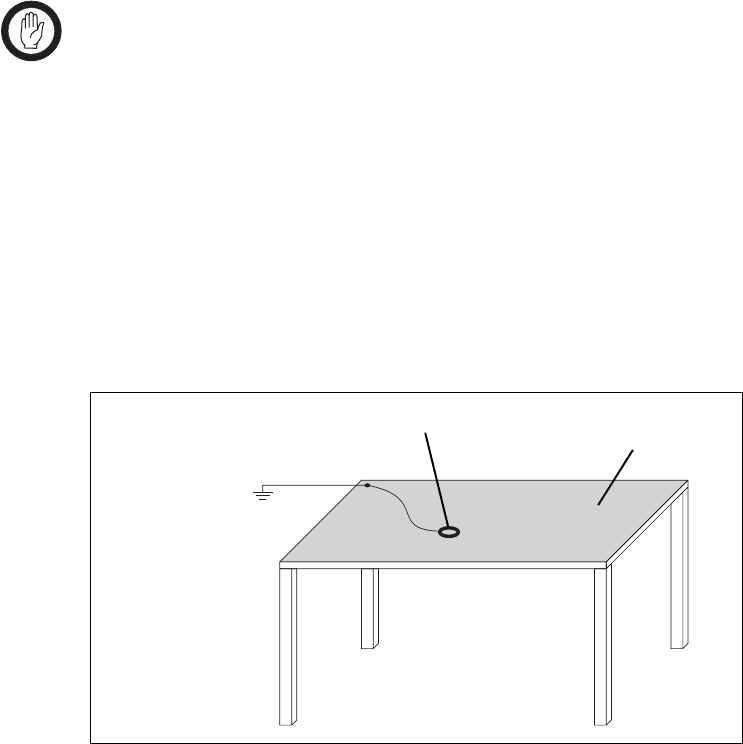
We recommend you purchase an antistatic bench kit from a reputable
manufacturer and install and test it according to the manufacturer’s
instructions. Figure 5.1 shows a typical antistatic bench set-up.
You can obtain further information on antistatic precautions and the dangers
of electrostatic discharge (ESD) from standards such as ANSI/ESD
S20.20-1999 or BS EN 100015-4 1994.
Aerial Load
The TB8100 BSS equipment has been designed to operate safely under a
wide range of aerial loading conditions. However, we strongly recommend
that the transmitter should always be operated with a suitable load to prevent
damage to the transmitter output power stage.
Figure 5.1 Typical Antistatic Bench Set-up
common point ground
(building ground or
mains ground via 1M
ohm series resistor)
conductive wrist strap dissipative rubber
bench mat
TB8100 Installation and Operation Manual Installation 61
© Tait Electronics Ltd March 2004
Equipment Grounding
To ensure safe operation the TB8100 BSS equipment must be correctly
grounded as described in these installation instructions.
Installation and Servicing Personnel
The TB8100 BSS should be installed and serviced only by qualified
personnel.
5.3 Regulatory Information
Distress Frequencies
The 406 to 406.1MHz frequency range is reserved worldwide for use by
Distress Beacons. Do not program transmitters to operate in this frequency
range.
FCC Compliance
This device complies with part 15 of the FCC Rules. Operation is subject
to the condition that this device does not cause harmful interference.
Unauthorised Modifications
Any modifications you make to this equipment which are not authorised by
Tait Electronics Ltd may invalidate your compliance authority’s approval to
operate the equipment.
5.4 Environmental Conditions
Operating Temperature Range
The operating temperature range of the TB8100 BSS is –30°C to +60°C
(–22°F to +140°F) ambient temperature. Ambient temperature is defined
as the temperature of the air at the intake to the cooling fans.
Humidity
The humidity should not exceed 95% relative humidity through the
specified operating temperature range.
62 Installation TB8100 Installation and Operation Manual
© Tait Electronics Ltd March 2004
Dust and Dirt
For uncontrolled environments, the level of airborne particulates must not
exceed 100µg/m3.
5.5 Grounding and Lightning Protection
Electrical Ground
The TB8100 BSS modules are grounded by physical contact between the
module case and the subrack. To ensure a good ground connection you
must tighten each module retaining clamp securely (refer to “Final
Reassembly” on page 81 for the correct torque setting).
A threaded grounding connector is provided on the rear of the subrack for
connection to the site ground point (refer to “Connection” on page 83 for
more details).
Lightning Ground
It is extremely important for the security of the site and its equipment that
you take adequate precautions against lightning strike. While it is outside
the scope of this manual to provide comprehensive information on this
subject, the following guidelines apply:
■install a suitable lightning rod at the top of the tower and connect it to a
secure ground point with appropriate conductors and connectors
■position site buildings and equipment within the cone of protection
provided by the grounded tower
■protect all cables entering the site to prevent lightning energy from
entering site buildings.
5.6 Recommended Tools
It is beyond the scope of this manual to list every tool that an installation
technician should carry. However, the following tools are specifically
required for installing the TB8100 BSS:
■Pozidriv PZ3 screwdriver for the M6 screws used to secure the subrack
to the rack or cabinet, and also for the DC input terminals on the PMU
■Pozidriv PZ2 screwdriver for the M4 screws used to secure the module
retaining clamps
■0.25in or 6mm flat blade screwdriver for the fasteners used to secure the
front panel to the subrack
■8mm AF spanner for the SMA connectors.
TB8100 Installation and Operation Manual Installation 63
© Tait Electronics Ltd March 2004
You can also obtain the TBA0ST2 tool kit from your nearest Tait Dealer or
Customer Service Organisation. It contains the basic tools needed to install,
tune and service the TB8100 BSS.
5.7 Ventilation
Always ensure there is adequate ventilation around the TB8100 BSS. Do
not operate it in a sealed cabinet. You must keep the ambient temperature
within the specified range, and we strongly recommended that you ensure
that the cooling airflow is not restricted.
Important The cooling fans are mounted on the front panel and will
only operate when the panel is fitted correctly to the front
of the subrack. To ensure adequate airflow through the
BSS, do not operate it for more than a few minutes with the
front panel removed (e.g. for servicing purposes).
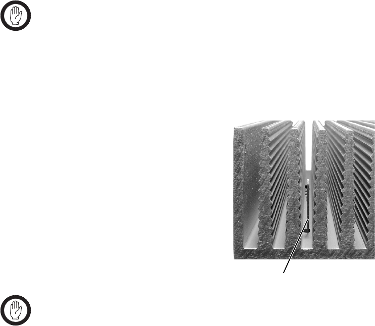
Ambient Air Temperature Sensor
The ambient air temperature reading
for the TB8100 BSS is provided by
the ambient air temperature sensor
PCB b fitted to the PA control PCB.
The sensor PCB is inserted through
slots in the control PCB and heatsink
to be positioned between the heatsink
fins.
Important If the sensor PCB is to provide accurate ambient tempera-
ture readings, it must have forced airflow and must not
come into contact with the metal of the heatsink fins. Do
not stack PAs with the fins together. It is possible for
the fins on one heatsink to slide between the fins on the
other heatsink. This can damage the sensor PCB, and pos-
sibly result in the heatsink fins becoming locked together.
b

64 Installation TB8100 Installation and Operation Manual
© Tait Electronics Ltd March 2004
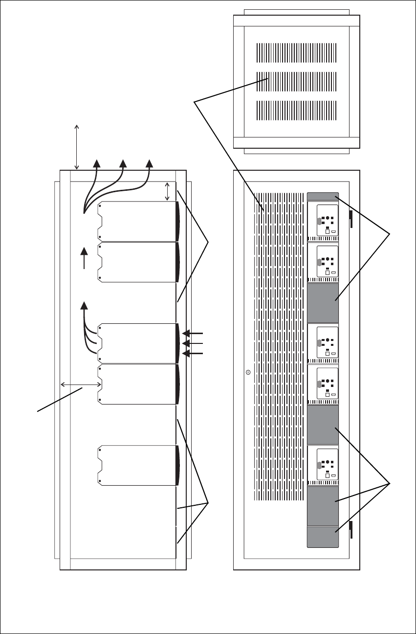
Cabinet and Rack Ventilation
Refer to Figure 5.2 on page 65.
The cooling airflow for the TB8100 BSS enters through the front panel and
exits at the rear of the subrack. For optimum thermal performance, the
heated air that has passed through a BSS must not be allowed to re-enter the
air intakes on the front panel. Any space at the front of the cabinet not
occupied by equipment should be covered by a blanking panel.
To allow enough cooling airflow through a cabinet-mounted BSS, we
recommend the following:
■an area of at least 150cm2 (23in2) of unrestricted ventilation slots or holes
in front of the air intakes for the fans for each subrack; for example,
thirty 6x85mm (0.25x3.3in) slots will allow the recommended airflow
■a vent in the top of the cabinet with an area of approximately 150cm2
(23in2) per subrack, or a similar area of ventilation per subrack at the rear
of the cabinet behind each subrack
■a 2U gap at the top of the cabinet.
Note The ventilation opening must be unrestricted. If the slots or holes
are covered with a filter, mesh or grille, the open area must be
increased to allow the same airflow as an unrestricted opening.
The maximum ambient temperature entering the cabinet must not exceed
+60°C (+140°F).
If the TB8100 BSS is installed in a rack or cabinet with other equipment
with different ventilation requirements, we recommend that the TB8100 be
positioned below this equipment.
Auxiliary Extractor
Fans The TB8100 BSS does not require auxiliary extractor fans mounted in the
top of the cabinet. If your cabinet is already fitted with fans, the following
procedures apply:
■if there are six or more 120mm (4.75in) fans, each capable of extracting
160m3 per hour (94.2CFM), they must run continuously
■if there are fewer than six fans, you must remove them and ensure the
vent in the top of the cabinet has an area of approximately 150cm2
(23in2) per subrack.
If you have any other configuration, the performance of your system will
depend on how closely you comply with the TB8100 BSS airflow
requirements described above.
TB8100 Installation and Operation Manual Installation 65
© Tait Electronics Ltd March 2004
Figure 5.2 Typical Cabinet Ventilation Requirements
bventilation slots dairflow entry
cblanking panels eairflow exit
20cm
(8in)
2U
t17.5cm
(t7in)
side view front view
top view
c
c
d
e
b
c
c
66 Installation TB8100 Installation and Operation Manual
© Tait Electronics Ltd March 2004
5.8 Installing the Base Station System
Caution A TB8100 subrack complete with modules can
weigh up to 28kg (62lb), or up to 30kg (66lb) com—
plete with packaging. We recommend that, once
the equipment is out of the carton, you remove the
modules from the subrack before moving the equip—
ment again. Otherwise, have another person help
you with the lifting. In all cases follow safe lifting
practices.
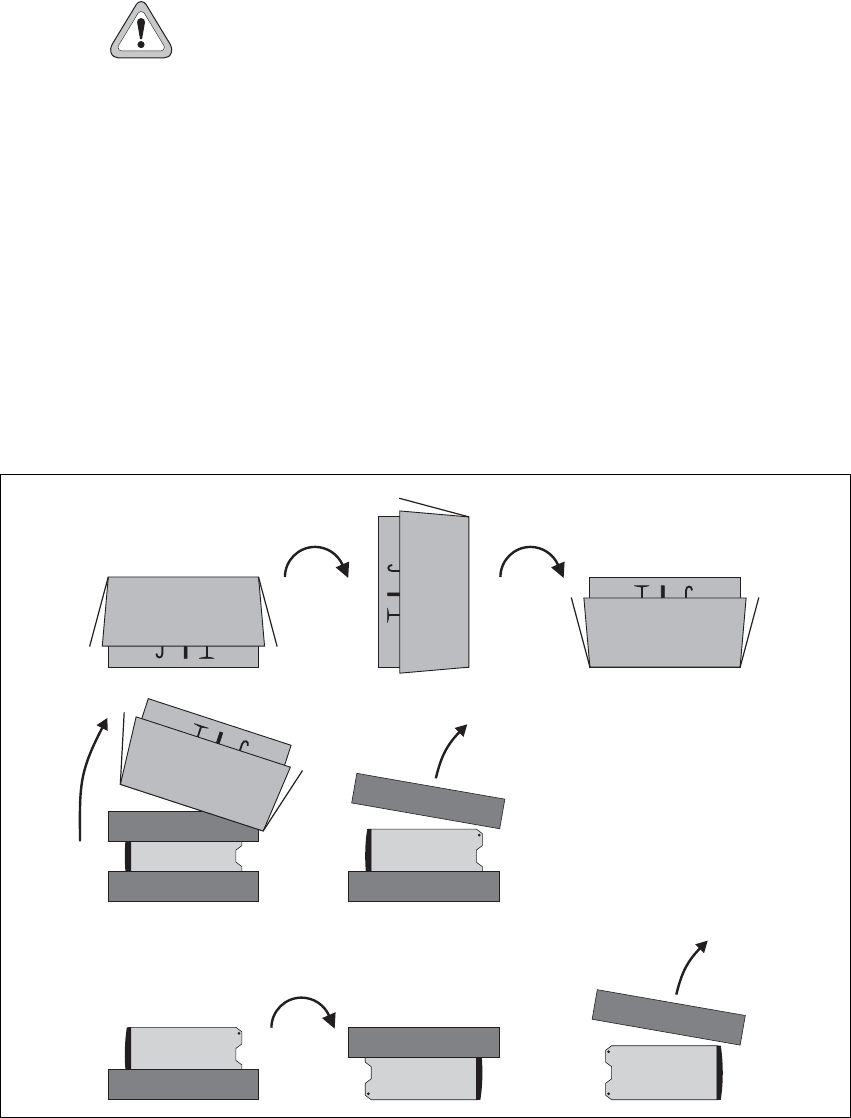
Unpacking the Equipment
Unpacking the
TB8100 BSS The TB8100 BSS is packed in a strong corrugated cardboard carton with
top and bottom foam cushions. To prevent personal injury and damage to
the equipment, we recommend that two people unpack the BSS.
1. Cut the tape securing the flaps at the top of the carton and fold them
flat against the sides b.
2. Rotate the carton carefully onto its side c and then onto its top d,
ensuring that none of the flaps is trapped underneath.
Figure 5.3 Unpacking the TB8100 BSS
b
e
g
f
hi
cd
TB8100 Installation and Operation Manual Installation 67
© Tait Electronics Ltd March 2004
3. Slide the carton upwards over the foam cushions and lift it away e.
Remove the cushion from the bottom of the BSS f.
4. Rotate the BSS and cushion carefully over the rear of the BSS g so
that the BSS is the right way up with the cushion on top h. Remove
the cushion from the top of the BSS i.
Disposal of
Packaging If you do not need to keep the packaging, we recommend that you recycle
it according to your local recycling methods. The foam cushions are CFC-
and HCFC-free and may be burnt in a suitable waste-to-energy combustion
facility, or compacted in landfill.
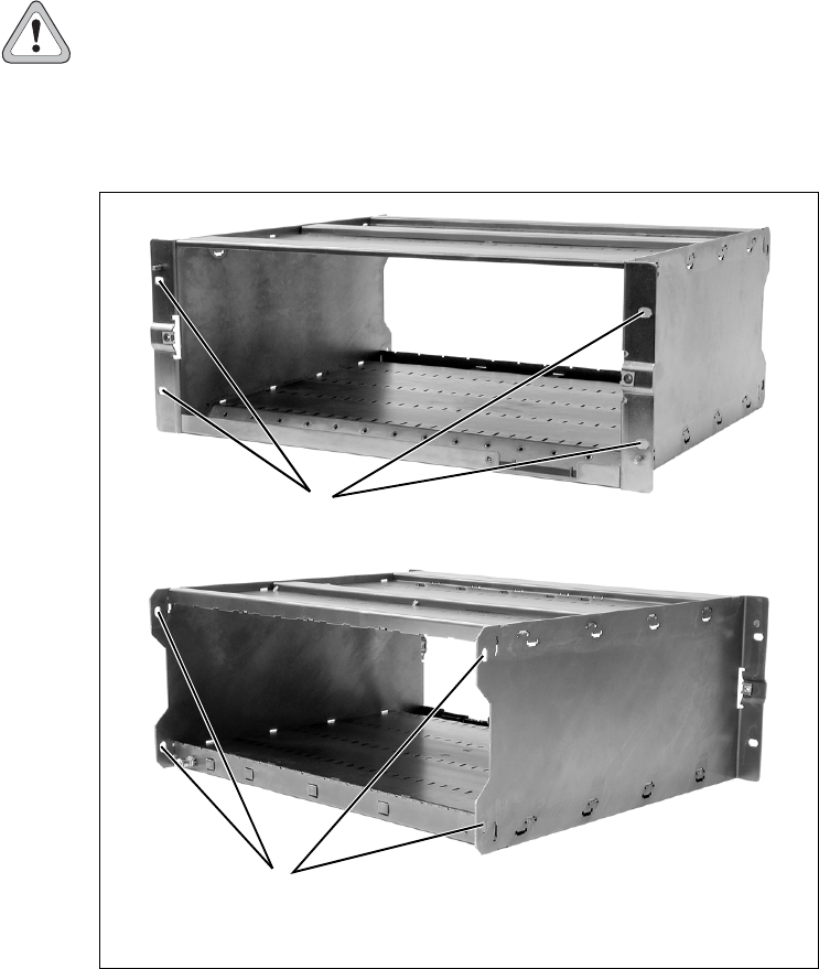
Mounting the Subrack
Caution We recommend that you remove the modules from
the subrack before lifting it (refer to “Replacing
Modules” on page 71), or have another person help
you with the lifting.
Figure 5.4 Subrack Mounting Points
bmain mounting holes — front cauxiliary mounting holes — rear
front view
rear view
b
c
68 Installation TB8100 Installation and Operation Manual
© Tait Electronics Ltd March 2004
1. Remove the front panel, as described in “Preliminary Disassembly”
on page 71.
2. Fit the subrack into the cabinet or rack and secure it firmly with an
M6 screw, flat and spring washer in each of the four main mounting
holes b, as shown in Figure 5.4 on page 67.
Note If you need extra mounting security, there are additional mount-
ing holes c provided at the rear of the subrack for auxiliary sup-
port brackets.
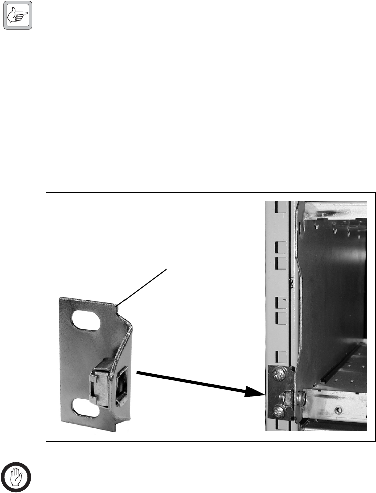
Auxiliary Support Bracket
TBA2140 auxiliary support brackets can be fitted to the rear of the TB8100
subrack to provide additional mounting security. Figure 5.5 below shows a
standard TBA2140 bracket b fitted in a typical Tait Electronics cabinet c.
If you are not using a Tait cabinet, you may have to make your own brackets
to suit your installation.
Important Yo u must fit the auxiliary support brackets if you intend to
transport a cabinet fitted with a fully built-up TB8100 BSS.
We also recommend that you fit the brackets under the following
conditions:
■when the installation is in an area prone to earthquakes
■when third party equipment is installed hard up underneath the TB8100
BSS subrack.
Figure 5.5 Auxiliary Support Bracket
c
b
TB8100 Installation and Operation Manual Installation 69
© Tait Electronics Ltd March 2004
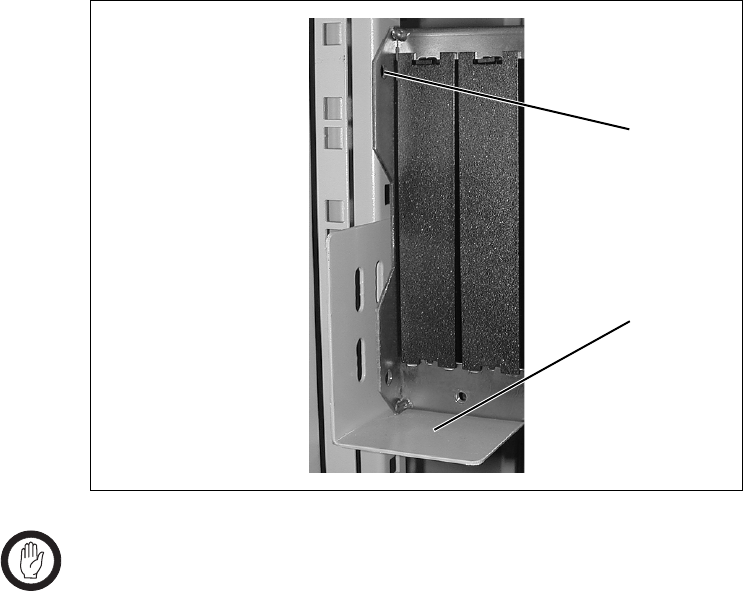
Optional Slide Mounting Rails
You can also use TBA2141 slide mounting rails b when mounting the
TB8100 BSS in a cabinet, as shown in Figure 5.6 below. These rails will
support the BSS while you slide it into the cabinet.
However, you must still secure the BSS to the cabinet with four M6 screws
through the main mounting holes on the front of the subrack, as shown in
Figure 5.4 on page 67.
Important The slide mounting rails are not suitable for transporting a
cabinet fitted with a fully built-up TB8100 BSS. In this
case, you must also fit the TBA2140 auxiliary support
brackets to the upper set of rear mounting holes c.
Cabling
General We recommend that you try to route all cables to and from the TB8100 BSS
along the side of the cabinet so the cooling airflow is not restricted.
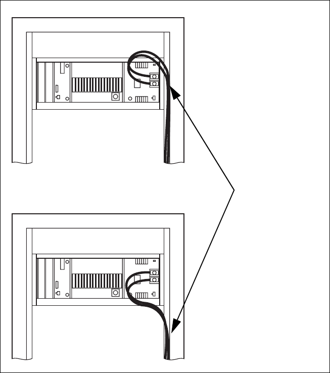
DC Power Cabling DC power cables should be well supported so that the terminals on the
PMU and on the ends of the cables do not have to support the full weight
of the cables.
Figure 5.6 Optional Slide Mounting Rail — Rear View
b
c
70 Installation TB8100 Installation and Operation Manual
© Tait Electronics Ltd March 2004
Figure 5.7 below shows two recommended methods of securing these cables
to prevent straining either set of terminals.
Figure 5.7 DC Power Cabling
secure the cables to the
cabinet to support their
weight
TB8100 Installation and Operation Manual Connection 83
© Tait Electronics Ltd March 2004
7 Connection
Once the TB8100 BSS hardware is installed, you need to connect the
individual modules to each other, and to any ancillary equipment required
in your system. This chapter provides information on all the inputs and
outputs available on the TB8100 BSS.
7.1 Overview of Inputs and Outputs
This section identifies the main input and output connections for the
TB8100 BSS. Figure 7.1 below identifies the connections at the front of a
dual base station, and Figure 7.3 on page 85 identifies those at the rear.
Figure 7.2 on page 84 identifies the connections at the front of a single
100W base station. Figure 7.4 on page 85 and identifies the connections on
the control panel. Refer to the following sections in this chapter for more
details on these connections.
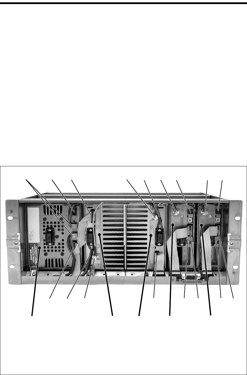
Figure 7.1 Dual 5 or 50W Base Station Inputs and Outputs — Front View
b28VDC high current output for PA f28VDC high current input cable from PMU
c28VDC low current output for reciter gRF output to PA
dsystem control bus h28VDC low current input from PMU
eRF input from reciter iDC output (for optional reciter fan only)
bcd e ghfgh
ddidiefd
PA 1 PA 2 reciter 2PMU reciter 1
84 Connection TB8100 Installation and Operation Manual
© Tait Electronics Ltd March 2004
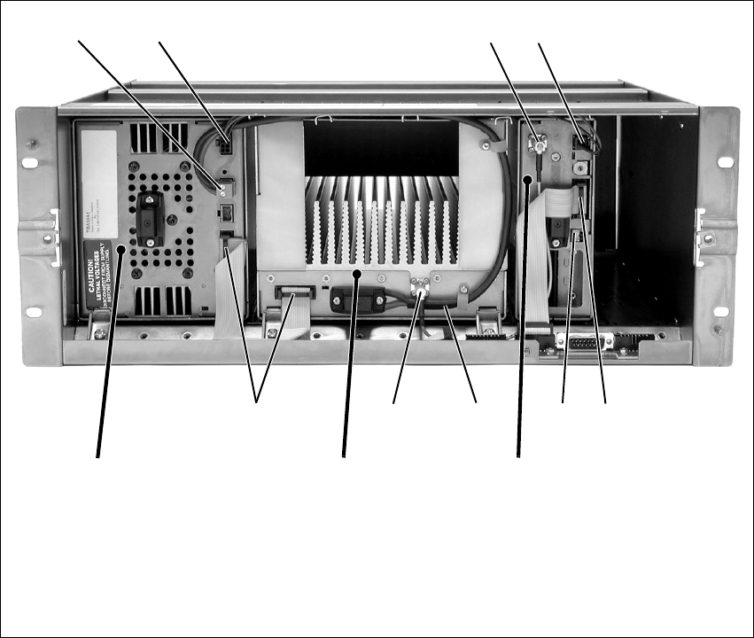
Figure 7.2 Single 100W Base Station Inputs and Outputs — Front View
b28VDC high current output for PA fsystem control bus
c28VDC low current output for reciter gDC output (for optional reciter fan only)
dRF output to PA h28VDC high current input cable from PMU
e28VDC low current input from PMU iRF input from reciter
bc de
hfgfi
PA reciter
PMU
TB8100 Installation and Operation Manual Connection 85
© Tait Electronics Ltd March 2004
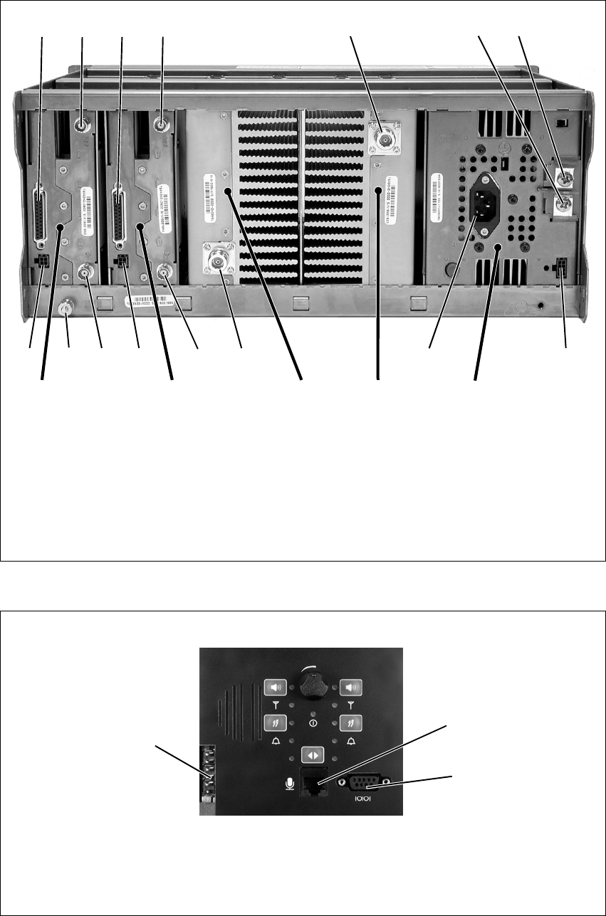
Figure 7.3 Dual 5 or 50W Base Station Inputs and Outputs — Rear View
bsystem interface connector gauxiliary 12VDC output
cexternal reference frequency input hAC mains input
dRF output iRF input
e–VDC input jauxiliary 12VDC input for system interface
f+VDC input 1) subrack ground connector
bc d fe
higidjj
PA 1PA 2reciter 1reciter 2 PMU
bc
1)
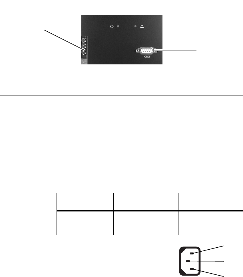
Figure 7.4 Standard Control Panel Inputs and Outputs
bDC outputs for fans mounted on front panel;
also used for fan rotation detectors (if fitted)
dRS-232 programming port
cmicrophone connector
b
c
d
86 Connection TB8100 Installation and Operation Manual
© Tait Electronics Ltd March 2004
7.2 Power Supply Connections
AC Power The TB8100 PMU is designed to accept a mains input of 88 to 264VAC at
45 to 65Hz. We recommend that a standard 3-wire grounded outlet is used
to supply the AC power. The socket-outlet must be installed near the
equipment and must be easily accessible. This outlet should be connected
to an AC power supply capable of providing a maximum of 600W. The
requirements of two typical AC supplies are given in the following table.
Your TB8100 BSS should come supplied
with a power supply cord to connect the
male IEC connector on the PMU to the
local AC supply. The pins of the IEC
connector on the PMU are identified at
right.
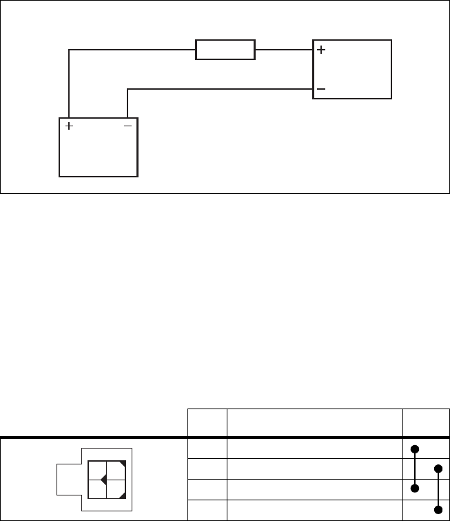
DC Power The TB8100 PMU is designed to accept a DC input of 10.3 to 15.5VDC
with negative or positive ground. There is a minimum DC start-up
threshold to prevent damaging a battery which has little capacity left.
You must connect the DC supply from the battery to the PMU via a fuse or
DC-rated circuit breaker with a rating of 60A. The DC input leads should
be of a suitable gauge to ensure less than 0.2V drop at maximum load over
the required length of lead.
Figure 7.5 Power Save Control Panel Outputs
bDC outputs for fans mounted on front panel;
also used for fan rotation detectors (if fitted)
cRS-232 programming port
b
c
Nominal Supply Current Requirement Circuit Breaker/Fuse
Rating
115VAC 8A 10A
230VAC 4A 6A
phase
neutral
ground
rear view
TB8100 Installation and Operation Manual Connection 87
© Tait Electronics Ltd March 2004
Terminate and insulate the DC input leads so they are protected from
accidentally shorting to the subrack if the PMU is removed before the leads
are disconnected.
Reciter Auxiliary DC
Input The system interface PCB in the reciter has an auxiliary DC input
connector. DC from the auxiliary DC output on the PMU (see “PMU
Auxiliary DC Output” below) can be supplied to the +AUX_V pin on the
system interface connector via this input.
The pin allocations for the auxiliary DC input on the system interface PCB
are given in the following table. Note that pins 1 & 3 and pins 2 & 4 on this
connector are linked. Refer to “System Connections” on page 89 for the
pin allocations for +AUX_V on each system interface PCB.
The DC output from the PMU is 12VDC. Although this power output is
isolated, the negative side of the supply is grounded on the system interface
PCB to give a +V output.
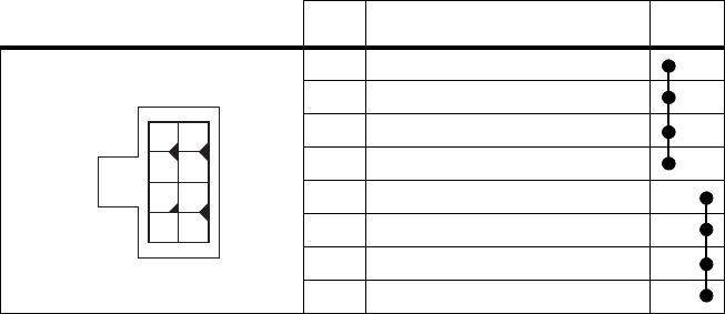
PMU Auxiliary DC
Output The PMU can provide an auxiliary DC output when it is fitted with the
optional 40W auxiliary power supply PCB. This power supply is current
limited to 3A and is available on the auxiliary DC output connector on the
rear panel. DC from this output can be supplied to the +AUX_V pin on
the system interface connector on the reciter via the auxiliary DC input
connector on the system interface PCB (see “Reciter Auxiliary DC Input”
above).
The pin allocations for the auxiliary DC output on the PMU are given in
the following table. Note that pins 1 to 4 and pins 5 to 8 on this connector
are linked.
Figure 7.6 Recommended DC Power Connection
Battery
PMU
Circuit Breaker
or Fuse
Pin Description Links
1+V input
2 ground
3+V input
4 ground
1
2
3
4
rear view
88 Connection TB8100 Installation and Operation Manual
© Tait Electronics Ltd March 2004
7.3 RF Connections
The RF input to the TB8100 BSS is via the lower BNC connector on the
rear panel of the reciter. The RF output is via the N-type connector on the
rear panel of the PA (refer to Figure 7.3 on page 85).
We recommend that you use dual-screened coaxial cable such as RG223 for
the BNC connections, and RG214 for the N-type connections.
Pin Description Links
1 +V output
2 +V output
3 +V output
4 +V output
5ground
6ground
7ground
8ground
1
5
26
37
48
rear view
TB8100 Installation and Operation Manual Connection 89
© Tait Electronics Ltd March 2004
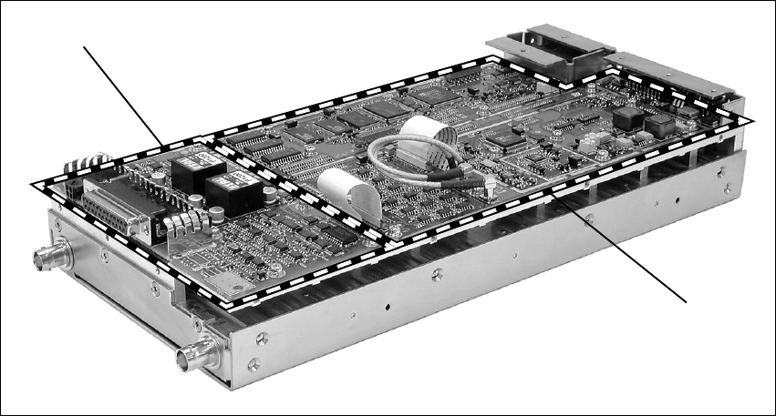
7.4 System Connections
The reciter can be fitted with an optional system interface PCB which
provides the links between the reciter’s internal circuitry and external
equipment. This PCB is securely mounted to the reciter’s chassis and is
connected to the control PCB with a flexible connector. The system
interface PCB is fitted with industry-standard connectors and several
standard types are available for different applications.
The circuitry on the system interface PCB provides additional signal
processing so that the outputs meet standard system requirements. It also
enables the PCB to identify itself to the reciter control circuitry.
The system interface PCB is removable, which makes it possible to change
the application of a reciter by removing one type of PCB and fitting another.
Only one system interface PCB can be fitted to a reciter at any one time.
This section provides details on the system interface PCBs available at the
time of publication. Other types may be developed for future applications.
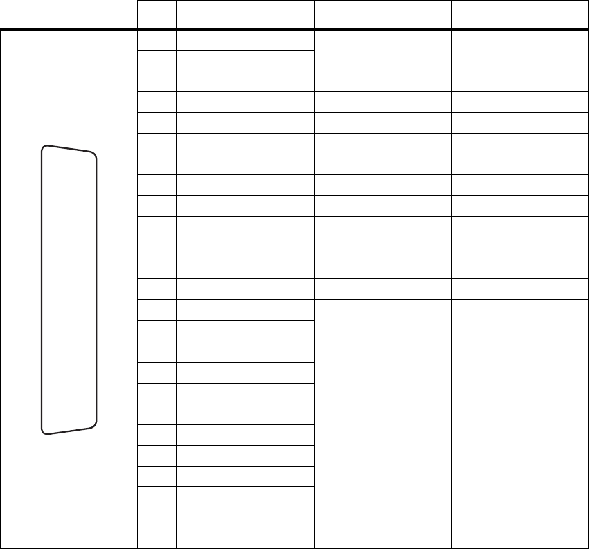
Standard The standard system interface PCB is fitted to reciters bearing the product
code TBA4xxx-0A0x or TBA5xxx-0A0x. If purchased separately, it has the
product code TBA10A0. It provides:
■non-isolated 600: balanced audio I/O
■high impedance unbalanced audio I/O
■Tx key
■Rx gate
■RSSI
■Tx relay
Figure 7.7 System Interface PCB
system interface PCB*
control PCB
*standard system interface PCB shown
90 Connection TB8100 Installation and Operation Manual
© Tait Electronics Ltd March 2004
■digital I/O.
It is fitted with a 25-way female D-range connector and an auxiliary DC
input connector. The pin allocations are listed in the table below.
Pin Signal Name Signal Type Notes
1 Rx line out + audio output non-isolated
AC coupled line
2 Rx line out –
3 Rx audio out audio output AC coupled
4 ground ground
5 Tx audio in audio input AC coupled
6 Tx line in + audio input AC coupled line
7 Tx line in –
8 RSSI DC signal
9 Rx gate output open collector
10 Tx key input
11 digital out 1 output open collector
12 digital out 2
13 +AUX_V power output
14 digital in 1
input 5V logic
15 digital in 2
16 digital in 3
17 digital in 4
18 digital in 5
19 digital in 6
20 digital in 7
21 digital in 8
22 digital in 9
23 digital in 10
24 Tx relay output open collector
25 ground ground
B
C
D
E
F
G
H
I
J
1)
1!
1@
1#
1$
1%
1^
1&
1*
1(
2)
2!
2@
2#
2$
2%
rear view
TB8100 Installation and Operation Manual Connection 91
© Tait Electronics Ltd March 2004
Isolated This system interface PCB is fitted to reciters bearing the product code
TBA4xxx-0B0x or TBA5xxx-0B0x. If purchased separately, it has the
product code TBA10B0. It is the same as the standard model, except that
the balanced audio interfaces are galvanically isolated.
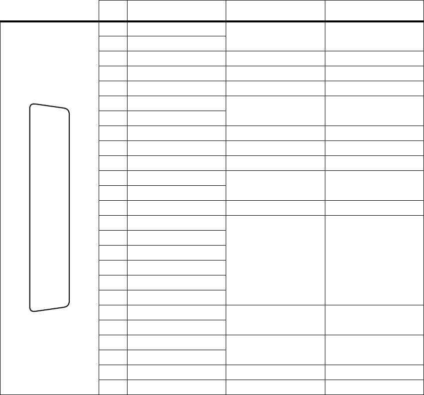
Isolated E&M This system interface PCB is fitted to reciters bearing the product code
TBA4xxx-0C0x or TBA5xxx-0C0x. If purchased separately, it has the
product code TBA10C0. It provides:
■isolated balanced audio I/O
■opto-isolated keying
■opto-isolated gate output.
It is fitted with a 25-way female D-range connector and an auxiliary DC
input connector. The pin allocations are listed in the table below.
Pin Signal Name Signal Type Notes
1 Rx line out + audio output transformer isolated line
2 Rx line out –
3 Rx audio out audio output
4 audio ground ground
5 Tx audio in audio input
6 Tx line in + audio input transformer isolated line
7 Tx line in –
8 RSSI DC signal
9 Rx gate output open collector
10 Tx key input
11 digital out 1 output open collector
12 digital out 2
13 +AUX_V power output
14 digital in 1
input 5V logic
15 digital in 2
16 digital in 3
17 digital in 4
18 digital in 5
19 digital in 6
20 opto +/– isolated keying input
21 opto –/+
22 relay +/– isolated gate output
23 relay –/+
24 Tx relay output open collector
25 ground ground
B
C
D
E
F
G
H
I
J
1)
1!
1@
1#
1$
1%
1^
1&
1*
1(
2)
2!
2@
2#
2$
2%
rear view
92 Connection TB8100 Installation and Operation Manual
© Tait Electronics Ltd March 2004
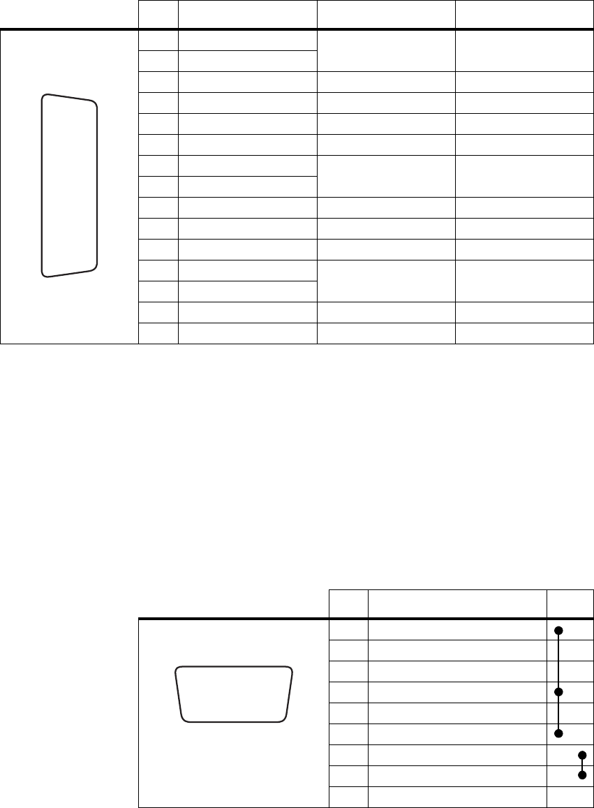
TaitN et This system interface PCB is fitted to reciters bearing the product code
TBA4xxx-0T1x or TBA5xxx-0T1x. If purchased separately, it has the
product code TBA10T1. It is designed for use with MPT trunking systems.
It is fitted with a 15-way female D-range connector and an auxiliary DC
input connector. The pin allocations are listed in the table below.
7.5 Service Kit Connections
The TB8100 service kit is connected to the BSS via the RS-232 serial port
on the control panel. This port is a 9-way female D-range connector. Use
a straight through cable, as supplied with the service kit, to connect your
programming computer to the BSS. The pin allocations for the serial port
are given in the following table. Note that pins 1, 4 & 6 and pins 7 & 8 are
linked. This port is also used for remote connection to the Service Kit or
Alarm Center software via a modem or radio modem.
Pin Signal Name Signal Type Notes
1 Rx line out + audio output AC coupled line
2 Rx line out –
3 Rx audio out audio output
4 Rx gate output open collector
5 Tx key input
6 Tx audio in audio input
7 Tx line in + audio input AC coupled line
8 Tx line in –
9 +AUX_V power output
10 digital out 3 output open collector
11 no connection
12 digital out 1 output open collector
13 digital out 2
14 digital in 1 input 5V logic
15 ground ground
J
B
C
D
E
F
G
H
I
1)
1!
1@
1#
1$
1%
rear view
Pin Description Links
1 not connected
2 receive data
3 transmit data
4 not connected
5ground
6 not connected
7 not connected
8 not connected
9 not connected
hj
b
gi
cdef
front view
TB8100 Installation and Operation Manual Connection 93
© Tait Electronics Ltd March 2004
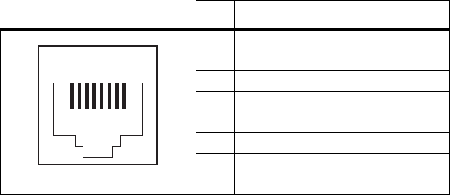
7.6 Microphone Connection
You can connect a microphone to the TB8100 BSS via the standard RJ45
socket on the control panel. If a standard TB8100 microphone has not been
supplied with your BSS, you should use an electret microphone. The pin
allocations for the microphone socket are given in the following table.
Pin Description
1not connected
2not connected
3not connected
4 PTT and hookswitch
5 voice band (microphone) input
6 microphone ground
7not connected
8not connected
12345678
front view
TBA8 (TR: Maint. Change act.proc/def.) is a standard SAP transaction code available within R/3 SAP systems depending on your version and release level.
Below for your convenience is a few details about this tcode including any standard documentation available. In-order to use this transaction within your SAP system simply enter it into the command input box located in the top left hand corner and press enter.
Here are a few additional command options available to use when doing this.
Program Name:
Screen Number: 0000
Parameter transaction: Yes
TBA8 is a parameter transaction so it actually executes a differnet tcode. This is while when you debug TBA8 it will actualy show
a different tcode based on the parameter value below. Note if the the tcode within the parameter includes /* it means that it will call the transaction and skip the first screen. You can also use this yourself in the top left commend box to skip the first screen when calling a transaction.
Tcode Parameter: /*SM30 VIEWNAME=V_VORGBEA;UPDATE=X;
TBA8 Authorisation objects
To check if you have the required level of authorisation to run this and any transaction use SU53. Simply execute TBA8 and then execute /NSU53 immediately afterwards. A report of all authorisations checked will then be displayed…See check tcode authorisation for full details and screenshots.
SAP GUI Support for tcode TBA8
When a tcode is created you can select which SAP GUI it has support for from HTML, Java and the main Windows GUI you are probably most familiar with.


SAPGUI for HTML
TBA8 does not support the HTML web based GUI. The SAP GUI for HTML generates HTML pages for each screen of the SAP transaction so that it can be executed within a standard web browser. Please note there are technical restrictions and possible incompatibility issues with certain browsers which means some transaction functionality may not function correctly.
SAPGUI for Java
TBA8 does not support the Java based GUI. The SAP GUI for Java support provides more controls than the SAP GUI for HTML, but requires a plug-in to be downloaded and installed on the users PC so is less popular than the SAP GUI for HTML.
SAPGUI for windows
TBA8 does not support the Windows based GUI. Windows(WinGUI) support is the most popular option and transactions can be run under SAP GUI for Windows.
SAP Program associated with transaction TBA8
For further details and documentation see program
TBA8 SPRO IMG Menu Path
Related Tcodes
Search/List all SAP tcodes
SAP transaction related information