- Manuals
- Brands
- Deutz Manuals
- Engine
- TCD 2013 L06 4V: TCD 2013 L06 4V
Manuals and User Guides for Deutz TCD 2013 L06 4V: TCD 2013 L06 4V. We have 1 Deutz TCD 2013 L06 4V: TCD 2013 L06 4V manual available for free PDF download: Operation Manual
|
Title |
File Size |
Download Links |
|
2013 Deutz TCD L04-06 4V Instruction Manual — Care and maintenance work.pdf |
1Mb |
Download |
|
2013 Deutz TCD L04-06 4V Instruction Manual — Engine corrosion protection.pdf |
127kb |
Download |
|
2013 Deutz TCD L04-06 4V Instruction Manual — Engine description.pdf |
2.1Mb |
Download |
|
2013 Deutz TCD L04-06 4V Instruction Manual — Faults, causes and remedies.pdf |
86.3kb |
Download |
|
2013 Deutz TCD L04-06 4V Instruction Manual — General.pdf |
19.3kb |
Download |
|
2013 Deutz TCD L04-06 4V Instruction Manual — Maintenance.pdf |
501.3kb |
Download |
|
2013 Deutz TCD L04-06 4V Instruction Manual — Operating substances.pdf |
51.3kb |
Download |
|
2013 Deutz TCD L04-06 4V Instruction Manual — Operation Manual.pdf |
22.1kb |
Download |
|
2013 Deutz TCD L04-06 4V Instruction Manual — Operation.pdf |
158.9kb |
Download |
|
2013 Deutz TCD L04-06 4V Instruction Manual — Service.pdf |
30.3kb |
Download |
|
2013 Deutz TCD L04-06 4V Instruction Manual — Technical data.pdf |
81kb |
Download |
|
2015 Deutz Engine TCD Workshop Manual — General.pdf |
22.7kb |
Download |
|
2015 Deutz Engine TCD Workshop Manual — Job card overview.pdf |
20.1Mb |
Download |
|
2015 Deutz Engine TCD Workshop Manual — Special tools.pdf |
303.8kb |
Download |
|
2015 Deutz Engine TCD Workshop Manual — Standart tools.pdf |
97.7kb |
Download |
|
2015 Deutz Engine TCD Workshop Manual — Technical data.pdf |
206.9kb |
Download |
|
2015 Deutz Engine TCD Workshop Manual — User notes.pdf |
57.9kb |
Download |
|
Deutz — Workshop Manual BFM 1008F part 1.pdf |
2.5Mb |
Download |
|
Deutz — Workshop Manual BFM 1008F part 2.pdf |
2.2Mb |
Download |
|
Deutz 0312 1936 2011 Workshop Manual- competence level 3.pdf |
20.7Mb |
Download |
|
Deutz 0312 1936 2011 Workshop Manual.pdf |
20.7Mb |
Download |
|
Deutz 0312 4004 2011 Workshop Manual- competence level 2.pdf |
8.1Mb |
Download |
|
Deutz 1011 Parts Manual.pdf |
2Mb |
Download |
|
Deutz 1011F Workshop Manual.pdf |
4.9Mb |
Download |
|
Deutz 1012 1013 Operation and Maintenance Manual.pdf |
4Mb |
Download |
|
Deutz 1012-1013 Service Manual.pdf |
3.7Mb |
Download |
|
Deutz 1015 Service Manual.pdf |
2.9Mb |
Download |
|
Deutz 2008-2009 Parts Manual.pdf |
3.2Mb |
Download |
|
Deutz 2008-2009 Service Manual.pdf |
4.5Mb |
Download |
|
Deutz 2011 — Operation Manual.pdf |
2.8Mb |
Download |
|
Deutz 2012 Service Manual.pdf |
11.1Mb |
Download |
|
Deutz 226B Operation Manual.pdf |
8.8Mb |
Download |
|
Deutz 413 Parts Manual.pdf |
4.6Mb |
Download |
|
Deutz 912 Parts Manual.pdf |
4.4Mb |
Download |
|
Deutz 912-913 Service Manual.pdf |
2.8Mb |
Download |
|
Deutz 912-913 Workshop Manual Workshop Manual.pdf |
5.8Mb |
Download |
|
Deutz 912-913 Workshop Manual.pdf |
34.6Mb |
Download |
|
Deutz 914 Parts Manual.pdf |
4.4Mb |
Download |
|
Deutz 914 Service Manual.pdf |
2.8Mb |
Download |
|
Deutz Accessories Catalogue.pdf |
5.2Mb |
Download |
|
Deutz B-F L / B-FM 1011F — Engine Description.pdf |
1.2Mb |
Download |
|
Deutz B-F L / B-FM 1011F — Engine Operation.pdf |
170.4kb |
Download |
|
Deutz B-F L / B-FM 1011F — Engine Preservation.pdf |
20.6kb |
Download |
|
Deutz B-F L / B-FM 1011F — Faults, Causes and Remedies.pdf |
33.1kb |
Download |
|
Deutz B-F L / B-FM 1011F — General.pdf |
33.6kb |
Download |
|
Deutz B-F L / B-FM 1011F — Notes.pdf |
155.6kb |
Download |
|
Deutz B-F L / B-FM 1011F — Operating Media.pdf |
418kb |
Download |
|
Deutz B-F L / B-FM 1011F — Routine Maintenance.pdf |
316.7kb |
Download |
|
Deutz B-F L / B-FM 1011F — Service and Maintenance.pdf |
448.2kb |
Download |
|
Deutz B-F L / B-FM 1011F — Technical Specifications.pdf |
70.8kb |
Download |
|
Deutz BF4m1011F Engine Service Parts Manual.pdf |
4.2Mb |
Download |
|
Deutz BF4M1013C Spare Parts Catalogue.pdf |
3.1Mb |
Download |
|
Deutz BFM 1015 Workshop Manual.pdf |
3.9Mb |
Download |
|
Deutz D 2008-2009 Workshop Manual.pdf |
4.7Mb |
Download |
|
Deutz D 2011 w, TD 2011 w, TCD 2011 w Workshop Manual- competence level 2.pdf |
13.9Mb |
Download |
|
Deutz D 2011, TD 2011 Workshop Manual- competence level 2.pdf |
21.7Mb |
Download |
|
DEUTZ EMR3 — Diagnostic trouble codes DTC.pdf |
289.4kb |
Download |
|
Deutz Engine 1011F Werkstatthandbuch.pdf |
10.5Mb |
Download |
|
Deutz Engine 1011F Workshop Manual.pdf |
11.2Mb |
Download |
|
Deutz Engine 1012-1013 Workshop Manual.pdf |
4.8Mb |
Download |
|
Deutz Engine 2012 Operation Manual.pdf |
3.7Mb |
Download |
|
Deutz Engine 914 Operation Manual.pdf |
3.2Mb |
Download |
|
Deutz Engine BF6M 1013 Operation Manual.pdf |
3.3Mb |
Download |
|
Deutz Engine B-FL 1011F Operation Manual.pdf |
2.9Mb |
Download |
|
Deutz Engine B-FL-FM 2011 Operation Manual.pdf |
7.4Mb |
Download |
|
Deutz Engine BFM-2012 Workshop Manual.pdf |
8.8Mb |
Download |
|
Deutz Engine D2008 2009 Workshop Manual PDF.pdf |
3.8Mb |
Download |
|
Deutz Engine Fire Protection — Operation Manual.pdf |
22.7Mb |
Download |
|
Deutz Engine S-BV6-8-9M628 Operation Manual.pdf |
10.1Mb |
Download |
|
Deutz Engine TCD 2013 2V Workshop Manual.pdf |
31.6Mb |
Download |
|
Deutz Engines B_FM 1008_F Workshop Manual.pdf |
2.7Mb |
Download |
|
Deutz F3M 1011F, BF3M, F4M, BF4M Service Manual.pdf |
1.3Mb |
Download |
|
Deutz FL 411 Service Manual.pdf |
8.7Mb |
Download |
|
Deutz FL 413 Service Manual.pdf |
8.7Mb |
Download |
|
Deutz Serie 7 Agrotron Service Manual.pdf |
4.5Mb |
Download |
|
Deutz TCD 2012-2013 Service Manual.pdf |
3.9Mb |
Download |
|
Deutz TCD 2013 4V — Industry Workshop Manual.pdf |
647.1kb |
Download |
|
Deutz TCD 2015 Service Manual.pdf |
4Mb |
Download |
|
Deutz TCD 2015 V08 EMR3 Diagnostic trouble codes.pdf |
62.4kb |
Download |
|
Deutz TCD2012 Instruction Manual.pdf |
5.1Mb |
Download |
|
DEUTZ Trouble Code List EMR4.pdf |
996.4kb |
Download |
|
Dtc List Deutz Engine.pdf |
359.9kb |
Download |
|
EMS2 Deutz Fault Codes.pdf |
1.3Mb |
Download |
|
Gt-50dz Tow Tractor With Deutz Engine.pdf |
36.4Mb |
Download |
|
Tabela de Falhas Motor Deutz.pdf |
556.3kb |
Download |
The company provides after-sales services, diagnostics, scheduled, emergency and overhauls of industrial and marine diesel engines Deutz MWM.
Today, Deutz is one of the best manufacturers of diesel engines for cars, ships, agricultural and construction equipment. Modern technologies, high quality and reliability put
Deutz in line with such world giants as Cummins, Detroit Diesel and others. The range of diesel engines currently produced includes more than 50 models,
different in power and area of application. But all of them are united by one thing — advanced technologies, thanks to which Deutz products are so appreciated in the world.
MWM — Motoren Werke Manheim, formerly known as Deutz Power Systems GmbH, has more than 130 years of successful production of gas and diesel engines. The current product range of this traditional
German company includes engines for various applications with a unit power of 180 to 4000 kW.
The range of engines produced in Mannheim is distinguished by quality, individual technical solutions, reliability and durability. Engines are used in various equipment, both for stationary and
for mobile use: they are compact, lightweight and very economical in fuel consumption.
Created over many years of operation, the database of maintenance and repair manuals issued by the manufacturer allows qualified service of an extensive range of all engine
modifications manufactured by DEUTZ and MWM: 912, 913, 914, 1011, 1012, 1013, 1015, 2008, 2009, 2001 , 2012, 2013, TCD2012, TCD2013, TCD2015, TBD234, TBD616, TCD2016, TBD620,
TCD2020, BVM628, TBD645.
![]()
Operation Manual
TCD2012L04/06V2 TCD 2013 L04/06 V2

zRead and observe the information in this instruction manual. You will avoid accidents, retain the manufacturer’s warranty and have a fully functional, ready to use engine at your disposal.
zThis engine is exclusively for the purpose according to the scope of delivery — defined and built by the equipment manufacturer (use for the intended purpose). Any use above and beyond this is considered improper use. The manufacturer will not be liable for damages resulting from this. The user will bear the sole risk in this case.
zUse for the intended purpose also includes observance of the operating, maintenance and repair instructions specified by the manufacturer. The engine may only be used, maintained and repaired by persons who are familiar with it and instructed in the dangers.
zThe pertinent rules for the prevention of accidents and other generally recognised safety and industrial medicine rules must be observed.
zWhen the engine is running there is a danger of injury caused by:
—rotating / hot components
—engines with extraneous ignition
—ignition systems (high electrical voltage) Contact must be avoided!
zThemanufacturerwillnotbeliablefordamages resultingfromunauthorisedmodificationtothe engine.
Equally,manipulationstotheinjectionandcontrol system can affect the engine’s performance and the exhaust characteristics. Compliance with environmental regulations will no longer be guaranteed in this case.
zDo not alter, obstruct or block the area of the cool air supply to the fan.
The manufacturer will accept no liability for damages resulting from this.
zOnly DEUTZ original parts may be used when carrying out maintenance/repair work on the engine. These have been designed especially for your engine and ensure a trouble-free operation.
Failuretoobservethiswillleadtovoidingofthe warranty!
zMaintenance/cleaning work on the engine may only be carried out when the engine is not running and has cooled down.
When doing this, make sure that the electrical system is switched off (remove ignition key). The specifications for accident prevention with electrical systems (e.g. VDE-0100/-0101/ -0104/-0105 Electrical protective measures against dangerous touch voltages) must be observed.
Cover all electrical components tightly when cleaning with liquids.
zDo not work on the fuel system while the engine is running — Danger to life.
Wait (1 minute) for the engine to come to a standstill (pressure release), as system is under high pressure: there is a — Danger to life.
During the first trial run do not stand in the danger area of the engine (danger due to high pressure of leaks) — Danger to life.
—In case of leaks immediately contact the workshop.
—When working on the fuel system ensure that theengineisnotunintentionallystartedduring repairs — Danger to life.

Operation Manual
TCD 2012 L04/06 V2
TCD 2013 L04/06 V2
312 1890 en
Enginenumber:


Please enter the engine number here. This will simplify the handling of customer service, repair and spare parts queries (see Section 2.1).
Illustrationsanddatainthisinstructionmanualare subject to technical changes in the course of improvements to the engines. Reprinting and reproductions of any kind, even in part, require our written permission.

Foreword
Dear customer,
Theliquid-cooledenginesmade by DEUTZ are developed for a wide variety of applications. An extensive range of variants ensures that the respective special requirements are met.
Your engine is equipped according to the installation, i.e. not all the parts and components described in this instruction manual are installed on your engine.
We have done our best to clearly identify the differences, so that you can easily find the operating, maintenance and repair instructions relevant to your engine.
Please read these instructions before you start your engine and observe the operating and maintenance instructions.
We are at your service for any questions you may have in this matter.
Your
DEUTZAG
© 2005

1.General
2.Enginedescription
2.1Engine type
2.1.1Companyplate
2.1.2Location of company plate
2.1.3Enginenumber
2.1.4Cylindernumbering
2.2Engine diagrams
2.2.1Operation side TCD 2012 L04 2V
2.2.2Starter side
TCD 2012 L04 2V
2.2.3Operation side TCD 2012 L06 2V
2.2.4Starter side
TCD 2012 L06 2V
2.2.5Operation side TCD 2013 L04 2V
2.2.6Starter side
TCD 2013 L04 2V
2.2.7Operation side TCD 2013 L06 2V
2.2.8Starter side
TCD 2013 L06 2V
2.3Lube oil circuit
2.3.1Lube oil diagram (example)
2.4Fuel circuit
2.4.1Fueldiagram
2.5Coolant circuit
2.5.1Coolant diagram (example)
2.6Electrics
2.6.1Electrical cable connections for monitoring
3.Operation
3.1Initialcommissioning
3.1.1Fillingengineoil
3.1.2Fillingfuel
3.1.3Filling / bleeding cooling system
3.1.4Other preparations
3.2Starting
3.2.1Electrical starting
3.3Operation monitoring
3.3.1Engine oil pressure
3.3.2Coolant temperature
3.3.3Coolantlevel
3.4Shutting down
3.4.1Electrical shutdown
3.5Operating conditions
3.5.1Winter operation
3.5.2High ambient temperature, highaltitude
4.Operatingsubstances
4.1Lube oil
4.1.1Quality
4.1.2Viscosity
4.2Fuel
4.2.1Quality
4.2.2Winter fuel
4.3Coolant
4.3.1General
4.3.2Coolant preparation
5.Maintenance
5.1Maintenance schedule
5.2Maintenance diagram
5.3Maintenance work carried out
Contents
6.Care and maintenance
work
6.1Lubrication system
6.1.1Oil change intervals
6.1.2Checking oil level, changing engine oil
6.1.3Changing oil filter
6.1.4Cleaning / changing oil filter (cup)
6.2Fuel system
6.2.1Changing fuel filter
6.2.3Fuel pre-filter, changing / bleeding
filter insert
6.3Cooling system
6.3.1Cleaning intervals
6.3.2Cleaning cooling system
6.3.3Emptying cooling system
6.3.4Filling / bleeding cooling system
6.4Combustion air filter
6.4.1Cleaning intervals
6.4.2Emptying cyclone pre-separator
6.4.3Cleaning oil bath air filter
6.4.4Dry air filter
6.5Belt drive
6.5.1Checking V-belt
6.5.2Changing V-rib belt
6.5.3Checking wear limit of V-rib belt
6.6Setting work
6.6.1 Checking valve clearance, setting if necessary
6.6.2 Setting control piston clearance in exhaust gas recirculation (EGR)
|
6.6.3 Diagram for setting valve / control |
2005 |
|
piston clearance |
|
|
© |

Contents
6.7Add-on parts
6.7.1Battery
6.7.2Three-phase current generator
6.7.3Transportation suspension
7.Faults, causes and remedies
7.1Faulttable
7.2Enginemanagement
7.2.1Engine protection function of the electronic engine controller EMR3
7.2.2Using the diagnosis button
7.2.3Table of fault blink codes
8.Enginecorrosionprotection
8.1Corrosion protection
9.Technical data
9.1Engine and setting data
9.2Screw tightening torques
9.3Tools
10. Service
© 2005
General
|
DEUTZ Diesel Engines |
Care and Maintenance |
Service |
1 |
|
are the product of many years of research and development. The resulting know-how, coupled with stringent quality standards, guarantee their long service life, high reliability and low fuel consumption.
It goes without saying that DEUTZ Diesel Engines meet the highest standards for environmental protection.
Sound care and maintenance practices will ensure that the engine continues to meet the requirements placed on it. Recommended service intervals must be observed and service and maintenance work carried out conscientiously. Special care should be taken under abnormally demanding operating conditions.
Please contact one of our authorized service representatives in the event of breakdowns or for spare parts inquiries. Our trained specialists will carry out repairs quickly and professionally, using only genuine spare parts. Original parts from DEUTZ AG are always produced in accordance with state- of-the-art technology.
The Technical Circulars listed in the instruction manual are obtainable from your DEUTZ partner.
Please turn to the end of this manual for further service information.
|
Beware of Running Engine |
Safety |
Asbestos |
Shut the engine down before carrying out maintenance or repair work. Ensure that the engine cannot be accidentally started. Risk of accidents!
When working on the running engine, work clothing must be close fitting.
Observe industrial safety regulations when running the engine in an enclosed space or underground.
When the work is complete, be sure to refit any panels and guards that may have been removed.Never fill the fuel tank while the engine is running.
This symbol is used for all safety warnings which, if not observed, present a direct danger to life and limb for the person involved. Please follow
them carefully. The attention of operating personnel should be drawn to these safety instructions. General safety and accident prevention regulations laid down by law must also be observed.
DEUTZ original parts are asbestos-free.
© 2005

Engine description
2
2.1Engine type
2.2Engine diagrams
2.3Lube oil circuit
2.4Fuel circuit
2.5Coolant circuit
2.6Electrics
© 2005
|
Engine description |
2.1 Engine type |
|
2 |
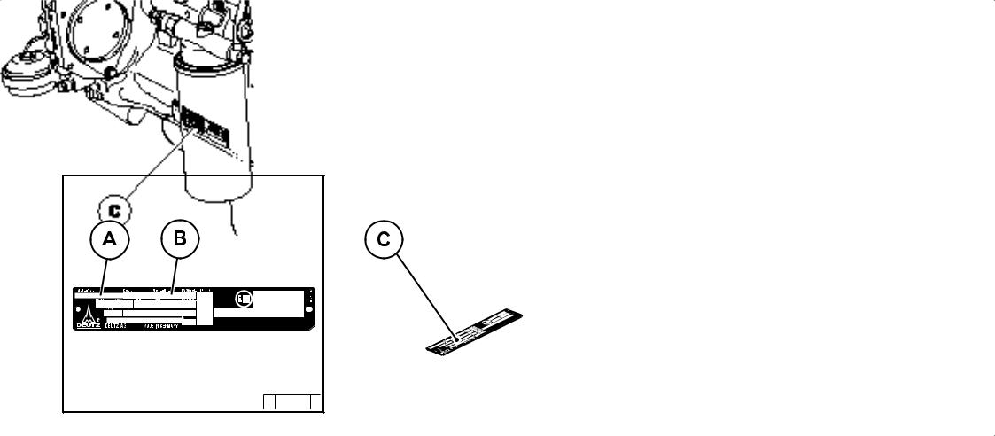
2.1.1 Company plate |
2.1.2 Location of company plate |
|
The engine type A, engine number B and the power data are stamped on the company plate. The engine type and number must be stated when purchasing spare parts.
|
© |
38 987 |
1 |
© |
43 834 |
0 |
|||
The company plate C is fixed to the cylinder head cover or the crankcase.
© 2005
|
2.1 Engine type |
Engine description |
|
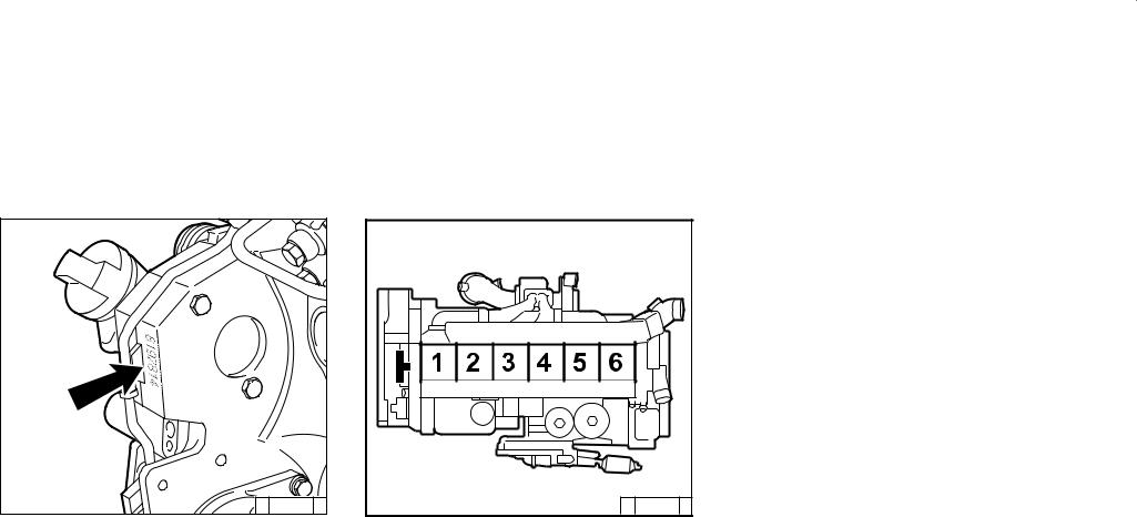
2.1.3 Engine number |
2.1.4 Cylinder numbering |
2 |
|
Theenginenumberisstampedonthecrankcase (arrow) and on the company plate.
The cylinders are counted consecutively, starting from the flywheel.
© 2005
![]()
|
Engine description |
2.2 Engine diagrams |
|
2 |
2.2.1 |
Operation side |
||
|
TCD2012L042V |
||||
|
1 |
Oil filler |
|||
|
2 |
Combustion air inlet |
|||
|
3 |
Cover |
|||
|
4 |
Fan |
|||
|
5 |
Generator |
|||
|
6 |
Fuel pump |
|||
|
7 |
Tension pulley with torsion spring |
|||
|
8 |
Oil cooler |
|||
|
9 |
Exchangeable fuel filter |
|||
|
10 |
Exchangeable lube oil filter |
|||
|
11 |
Oil tray |
|||
|
12 |
Hydraulic pump or compressor mounting |
|||
|
possibility |
||||
|
13 |
Flywheel |
|||
|
14 |
Crankcase bleeding valve |
|||
|
15 |
Transport eyes |
|||
|
16 |
Charge air pipe |
|||
|
17 |
Fuel control unit |
|||
|
© 2005 |
© 43 302 |
0 |
||
|
2.2 Engine diagrams |
Engine description |
|
2.2.2 |
Starter side |
|
|
TCD2012L042V |
||
|
© 44 303 |
0 |
2
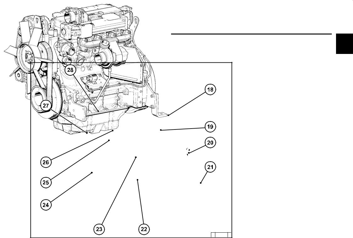
18Exhaust manifold
19Turbocharger
20Oil filler (optional)
21Engine mounting
22Oil return line from turbocharger
23Relay (starter)
24V-rib belt
25Coolant inlet
26Coolant outlet
27Coolant pump
28Connection cabin heater or compensation line
© 2005
|
Engine description |
2.2 Engine diagrams |
|
2 |
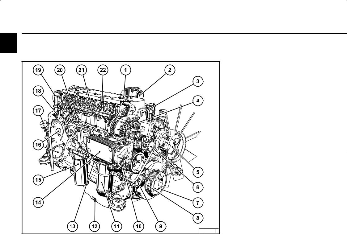
2.2.3 |
Operation side |
||
|
TCD2012L062V |
||||
|
1 |
Oil filler |
|||
|
2 |
Combustion air inlet |
|||
|
3 |
Transport eyes |
|||
|
4 |
Generator |
|||
|
5 |
Fan hub |
|||
|
6 |
Fuelpump |
|||
|
7 |
V-rib belt drive on crankshaft |
|||
|
8 |
V-rib belt |
|||
|
9 |
Tension pulley with torsion spring |
|||
|
10 |
Coolantpump |
|||
|
11 |
Exchangeable lube oil filter (1x optional) |
|||
|
12 |
Oil drain screw |
|||
|
13 |
Oil dipstick |
|||
|
14 |
Lube oil cooler |
|||
|
15 |
Exchangeable fuel filter |
|||
|
16 |
Hydraulic pump or compressor installation |
|||
|
(optional) |
||||
|
17 |
Oil filler (optional) |
|||
|
18 |
Plug to control unit |
|||
|
19 |
Crankcase bleeding valve |
|||
|
20 |
High-pressure pump (2) |
|||
|
21 |
Rail |
|||
|
22 |
Injector |
|||
|
© 2005 |
© 43 828 |
1 |
||
|
2.2 Engine diagrams |
Engine description |
|
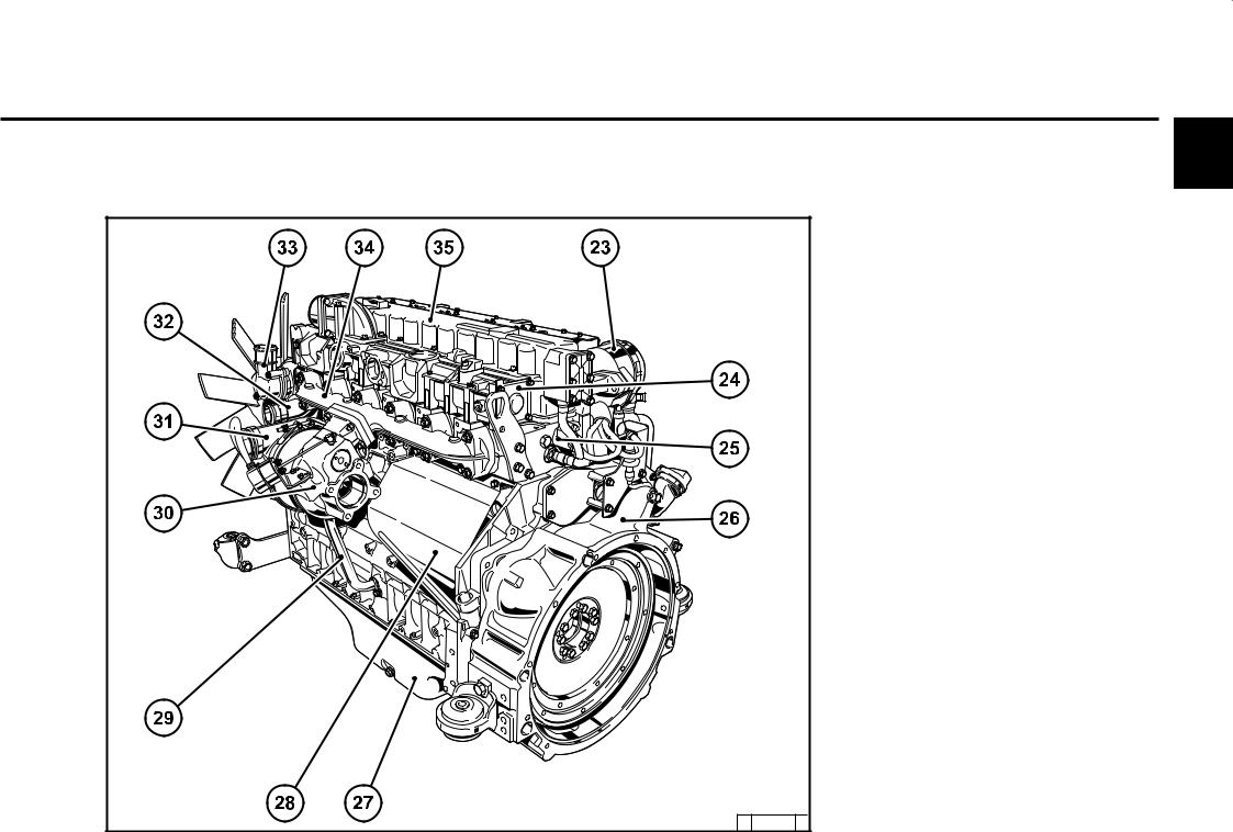
2.2.4 |
Starter side |
|
|
TCD2012L062V |
||
|
© 43829 |
2 |
2
23Crankcase bleeding valve
24Charge air pipe
25Solenoid valve for exhaust gas recirculation
26SAE housing
27Oil tray
28Starter cover
29Oil return line from turbocharger
30Exhaust turbocharger
31Charge air connection to charge air cooler
32Coolant inlet
33Coolant outlet
34Exhaust manifold
35Cylinder head cover
© 2005

|
Engine description |
2.2 Engine diagrams |
|
2 |
2.2.5 |
Operation side |
||
|
TCD2013L042V |
||||
|
1 |
Combustion air inlet |
|||
|
(heating flange installation facility, optional) |
||||
|
2 |
Connection cabin heater or compensation |
|||
|
line |
||||
|
3 |
Fan (drive coolant pump) |
|||
|
4 |
Generator |
|||
|
5 |
Belt pulley on crankshaft |
|||
|
6 |
V-belt |
|||
|
7 |
Fuel pump drive |
|||
|
8 |
Exchangeable fuel filter |
|||
|
9 |
Exchangeable lube oil filter |
|||
|
10 |
Oil cooler |
|||
|
11 |
Drive facility (e.g. hydraulic pump, |
|||
|
optional) |
||||
|
12 |
Oil return line crankcase bleeding |
|||
|
13 |
Plug to control unit |
|||
|
14 |
Fuel control unit |
|||
|
(Electronic Control Unit) |
||||
|
15 |
High-pressure pump |
|||
|
16 |
Crankcase bleeding valve |
|||
|
17 |
Injector |
|||
|
18 |
Oil filler |
|||
|
© 2005 |
© 43 899 |
1 |
||
|
2.2 Engine diagrams |
Engine description |
|
2.2.6 |
Starter side |
|
|
TCD2013L042V |
||
|
© 43 900 |
3 |
2
19Oil filler (optional)
20SAE housing
21Enginemounting
22Oil drain screw
23Oil tray
24Starter
25Lube oil return from turbocharger
26Turbocharger
27Coolantinlet
28Charge air connection to cooler
29Coolant outlet
30Exhaust manifold
31Charge air pipe
32Transport eyes
© 2005
|
Engine description |
2.2 Engine diagrams |
|
2 |
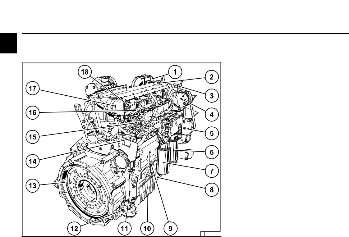
2.2.7 |
Operation side |
||
|
TCD2013L062V |
||||
|
1 |
Combustion air inlet |
|||
|
2 |
Oil filler |
|||
|
3 |
Transport eyes |
|||
|
4 |
Generator |
|||
|
5 |
Coolantpump |
|||
|
6 |
Exchangeable lube oil filter |
|||
|
7 |
Exchangeable fuel filter |
|||
|
8 |
Oil tray |
|||
|
9 |
Oil dipstick |
|||
|
10 |
Oil drain screw |
|||
|
11 |
Oil return line crankcase bleeding |
|||
|
12 |
Enginemounting |
|||
|
13 |
SAE housing |
|||
|
14 |
Plug to control unit |
|||
|
15 |
High-pressure pump |
|||
|
16 |
Rail |
|||
|
17 |
Crankcase bleeding valve |
|||
|
18 |
Injector |
|||
|
© 2005 |
© 43 924 |
0 |
||
|
2.2 Engine diagrams |
Engine description |
|
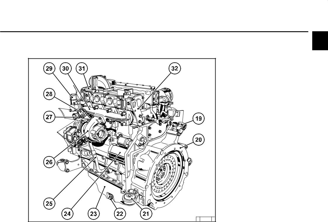
2.2.8 |
Starter side |
|
TCD2013L062V |
|
|
© 43 925 1 |
2
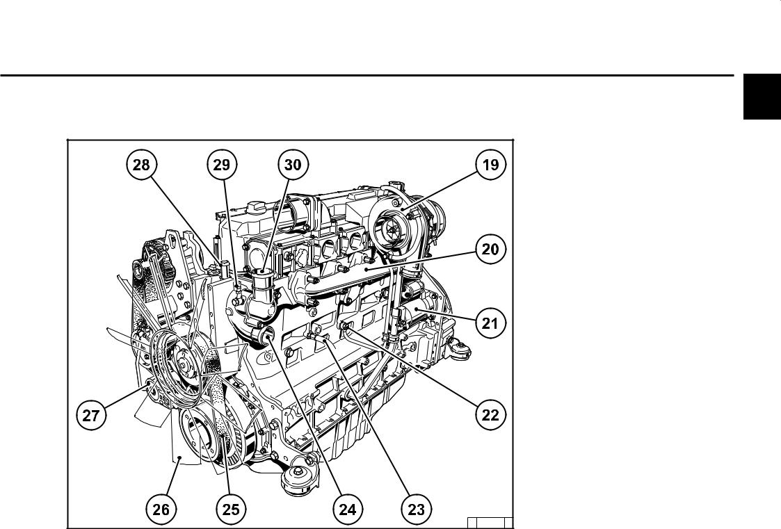
19Turbocharger
20Exhaust manifold
21Starter
22Lube oil line to turbocharger
23Coolant drain screw
24Coolantinlet
25V-rib belt
26Fan
27Tension pulley with torsion spring
28Connection compensation line
29Ventilation line to compensation tank
30Coolant outlet from engine to cooler
© 2005
|
Engine description |
2.3 Lube oil circuit |
|
2 |
2.3.1 Lube oil diagram (example) |
|
1 |
Oil tray |
|
|
2 |
Intakepipe |
|
|
3 |
Lube oil pump |
|
|
3.1 Safety valve |
||
|
4 |
Lube oil cooler |
|
|
4.1 Return shutoff valve (only in 2012) |
||
|
4.2 By-pass valve |
||
|
4.3 By-pass valve oil filter |
||
|
5 |
4.4 Pressure control valve |
|
|
Exchangeable lube oil filter |
||
|
6 |
Mainoilpipe |
|
|
6a Internal exhaust gas recirculation |
||
|
7 |
Crankshaft bearing |
|
|
8 |
Con rod bearing |
|
|
9 |
Camshaft bearing |
|
|
10 |
Line to injection nozzle |
|
|
11 |
Injection nozzle for piston cooling |
|
|
12 |
Tappet with rocker arm pulse lubrication |
|
|
13 |
Stop rod, oil supply for rocker arm |
|
|
lubrication |
||
|
14 |
Rocker arm |
|
|
15 |
Return line to oil tray |
|
|
16 |
Lube oil line toexhaust turbocharger |
|
|
17 |
Exhaust turbocharger |
|
|
18 |
Return line from compressor 2x |
|
|
19 |
Compressor or hydraulic pump |
|
|
20 |
Oil line to compressor or hydraulic |
|
|
pump |
||
|
21 |
Return line from exhaust turbocharger |
|
|
©2005 |
20 |
|
|
© 4339 893012 |
|
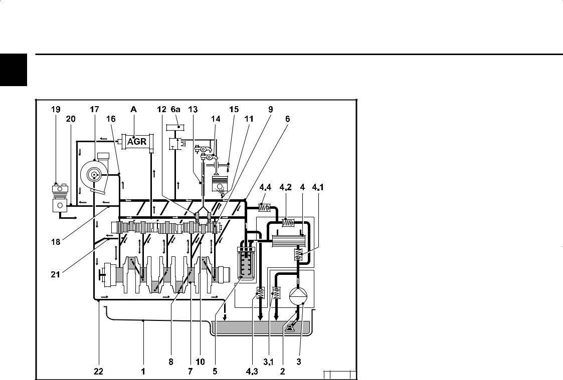
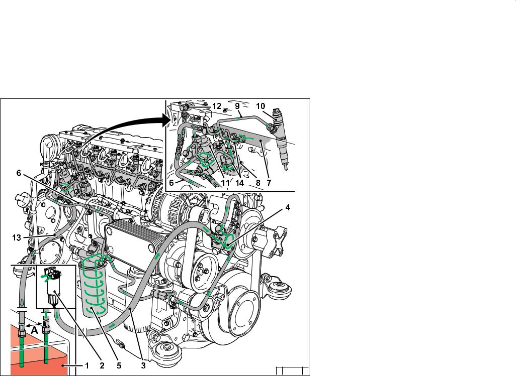
2.4 Fuel circuit |
Engine description |
1Fuel container
2Fuel pre-filter with pre-pressure pump possibility for filling the low pressure area (to be provided by the customer)
3Line to fuel pump
4Fuelpump
5Fuel filter
6Fuel supply line to fuel control unit
7Rail
8High-pressure pump
9Fuel line to injector
10Injectors
11Control block FCU (Fuel Control Unit)
12Fuel return at the cylinder head
13Fuel return line to the tank
14Fuel lines from the control block to the high — pressure pumps and to the rail
A min. distance 500 mm
© 2005

|
Engine description |
2.5 Coolant circuit |
|
2 |
2.5.1 |
Coolant diagram |
|
|
(example) |
|||

1Coolant outlet at the cooler
2Thermostat
3Coolant feed line to pump
4Coolantpump
5Lube oil cooler
6Cylinder cooling
7Cylinder head cooling
8Coolant inlet to heating
9Heating
10Coolant to thermostat
11Heating connection
12Compensation line
13Ventilation line to compensation tank
14Coolant outlet to cooler
15Compensation tank
16Compensation line to heat exchanger
© 2005

|
Engine description |
2.6 Electrics |
|
2 |
2.6.1 Electrical cable connections |
|||||||||||||||||||||
|
for monitoring |
||||||||||||||||||||||
1Solenoid valve EGR (optional)
2Coolant temperature
3Charge air pressure/temperature transmitter
4Connection facility example:
Control unit not mounted on the engine
5Engine control unit
6Speed governor via crankshaft
7Rail pressure, on side of rail
8Oil level transmitter (optional)
9Oil pressure transmitter
10Fuel pressure
11Speed governor via camshaft
12Central plug (for engine control)
13Power supply (battery)
14Multifunction displays
15Outputs (configurable, e.g. for lamps, torque (PWM), speed, engine running signal, etc.)
16Inputs (configurable) (PWM/digital/analogue)
17Accelerator pedal
18Hand throttle (optional)
19Switch functions (optional, e.g. for P factor, controller type, roof curves, fixed speeds, (etc. also multistage switches))
20Key switch Start/stop
21Diagnosis button
22Fault light with blink code
23Diagnosis interface / CAN-Bus

Other application-side components (depending on the application)
zWater trap fuel filter, see chap. 6.2.3
zOverride key, see chap. 3.3.1 (for temporary bypassing of the engine protection functions)
zCoolant level transmitter
zSeparate engine stop switch
zFan control
zSwitch for brake contact, engine brake, clutch
zDrive speed sensor, drive speed control unit (+ — keys, for speed increase reduction)
zCold start aid control lamp, see chap. 3.2.1
If there is a serious fault, e.g. the heating flange draws current although the control unit does not control it, this lamp flashes. The power supply to the heating flange must then be disconnected separately (overheating protection heating flange).
© 2005

Operation
3
3.1Initial commissioning
3.2Starting
3.3Operation monitoring
3.4Shutting down
3.5Operating conditions
© 2005
|
Operation |
3.1 Initial commissioning |
||
|
3 |
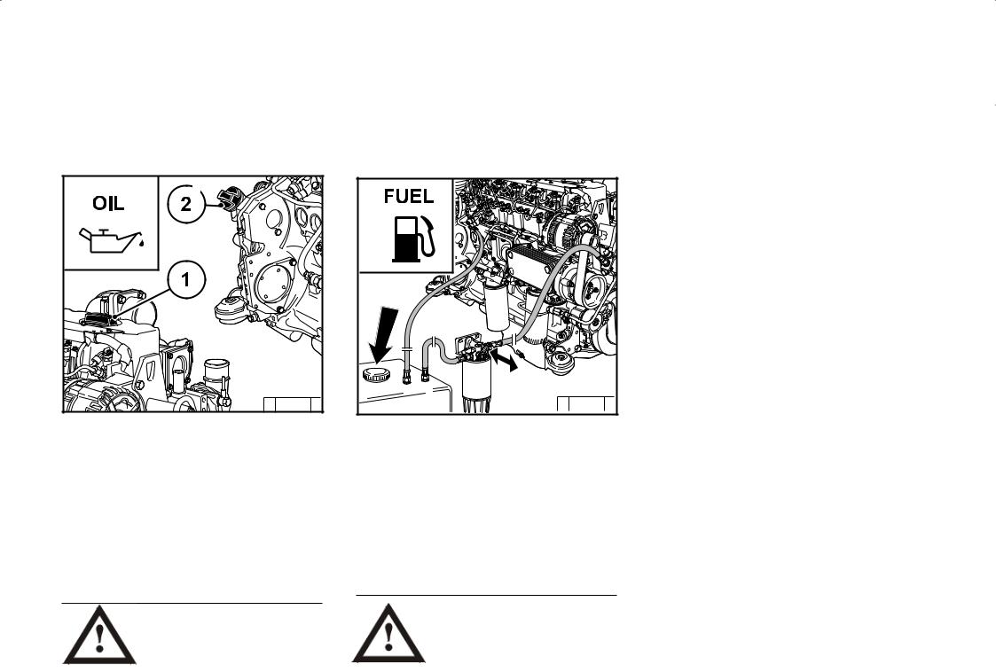
3.1.1 Filling engine oil |
3.1.2 Filling fuel |
|
© 2005
The engines are generally supplied without oil filling.
Fill engine with lube oil through the oil filler (1) on the cylinder head cover. Alternatively, you can fill on the wheel box (2) or on the side of the crankcase.
For oil filling amount see 9.1.
For quality and viscosity of oil see 4.1.
Oilmaynotbefilledintothedust collecting tank of the preseparator, if this is present.
Only use clean, standard, branded diesel fuel. For fuel quality see 4.2.
Depending on the outdoor temperature, use either summer or winter diesel fuel.
Bled the fuel low pressure system after filling, see 6.2.3.
Additional venting of the fuel system by a 5 minute trial run in idle or low load is absolutely essential.
Only re-fuel when the engine is not running!
Pay attention to cleanliness!
Do not spill any fuel!
|
3.1 Initial commissioning |
Operation |
||
|
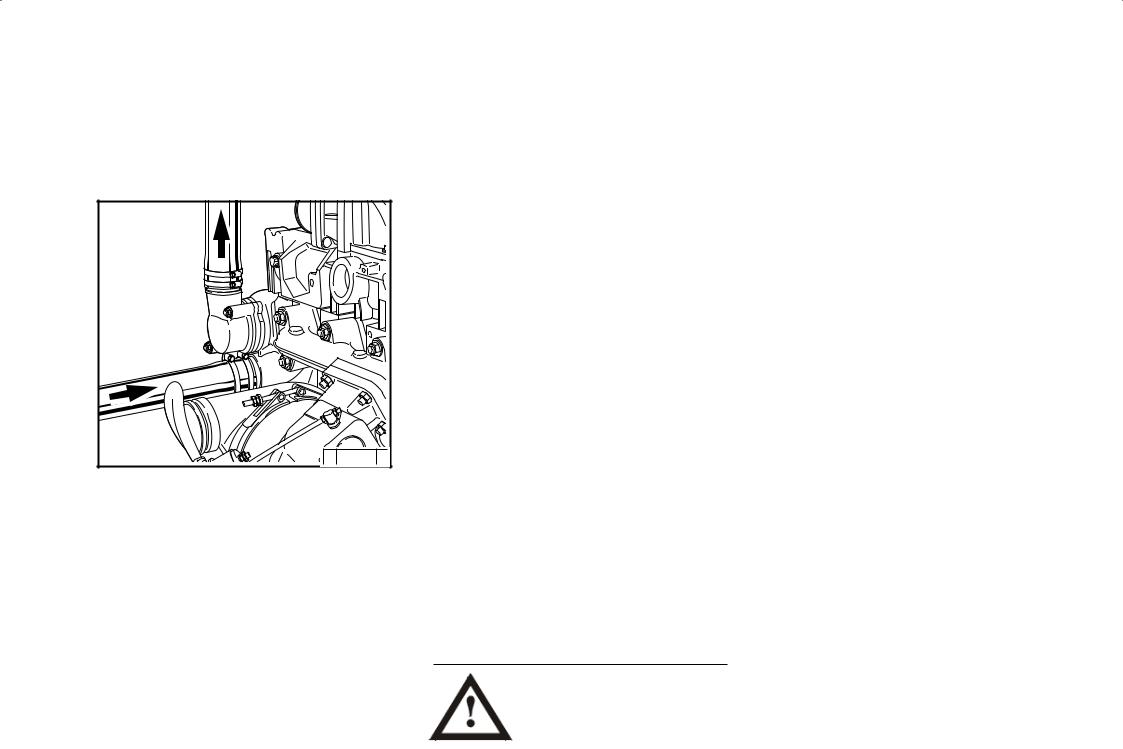
3.1.3 Filling / bleeding |
3.1.4 Otherpreparations |
3 |
|
|
coolingsystem |
|||
zConnectconnectioncoolantoutlet1andcoolant inlet 2 to the cooling system. Connect the lead line from the compensation tank to the water pump or to the coolant inlet pipe 2.
zConnect the bleed lines from the engine and poss. from the cooler to the compensation tank.
zFill the cooling system through the compensation tank.
zClose the compensation tank with the valve.
zStart the engine and run warm until the thermostat opens (line 1 heats up).
zEngine run with open thermostat 2 — 3 minutes.
zCheck the coolant level in the compensation tank and top up the coolant if necessary.
zRepeat the process with engine start if necessary.
Never operate the engine without coolant (not even briefly).
zCheck battery and cable connections, see 6.7.1.
zTrial run
—After preparations carry out a short trial run of approx. 10 min.
Do not fully load the engine.
During and after the trial run
— Check engine for tightness.
With engine not running
—Check oil level, re-fill oil if necessary, see 6.1.2
—Check V-belt, re-tighten if necessary, see 6.5.
zRunning-in
Check the oil level twice a day during the running-in phase.
After the running-in phase, checking once a day is sufficient.
© 2005
|
3 |
3.2.1 Electricalstarting |
|
|
Before starting make sure that |
||
|
there is nobody in the engine/ |
||
|
work machine danger area. |
||
|
After repairs: Check that all |
||
|
protective equipment is |
||
|
mounted and all tools have been removed |
||
|
from the engine. |
||
|
When starting with heating plugs/heating |
||
|
flange, do not use additional start aids (e.g. |
||
|
injection with start pilot)! Danger of accidents! |
||
|
z Engine is electronically controlled by |
||
|
Example: EMR3 (electronic engine control) |
||
|
— engine is programmed and supplied with |
||
|
the necessary function configurations. |
||
|
z As far as possible separate engine from |
||
|
driven devices by disconnecting. |
||
|
z Engine connector plug must be connected |
||
|
by the customer (e.g in driver’s cab/ |
||
|
device) to at least: |
||
|
— Supply voltage |
||
|
— Torque output |
||
|
— Speed output. |
||
|
z Warm up the engine for approx. 30 seconds |
||
|
at a low idling speed. |
||
|
z Do not run up the engine immediately to |
||
|
high idling speed / full load operation from |
||
|
cold. |
||
|
If the starter is connected by a relay on |
||
|
the EMR3, |
||
|
— the maximum starting time is limited by |
||
|
the EMR3. |
||
|
2005© |
— the pause between two start attempts |
|
|
is given by the EMR3. |
||
without cold start aid
z Insert key
— Step 0 = no operating voltage. z Turn key to the right
— Step 1 = operating voltage, — Warning lights light up.
z Turn the key further to the right against the spring load.
— Step 2 = start
z Release key as soon as the engine starts up. — Warning lights go out.
© 26 411 0
—If the touch start function is programmed, a short start command with the ignition key suffices in position 2 or, if available, by a start button.
Thestartisthencontinuedautomaticallybythe EMR3.
—For special applications, the EMR3 can be programmed by data record so that the control unit performs other automatic start attempts if the engine fails to start.
Start the engine for a maximum of 20 seconds uninterrupted. If the engine does not start up, wait for one minute and then repeat the starting process. If the engine does not start up after two starting processes, determine the cause as per fault table (see 7.1).
Iftheenginedoesnotstartandthediagnosticlamp flashes, the EMR3 system has activated the start lock to protect the engine.
The start lock is released by switching off the systemwiththeignitionkeyforabout30seconds.

3.2 Starting
with cold start aid
Heating plug/heating flange
© 26 411 0
zInsert key.
—Step 0 = no operating voltage.
zTurn key to the right.
—Step 1 = operating voltage,
—Warning lights 1+2+3 light up.
—Pre-heatuntilheatingindicatorgoesout.Ifthe pre-heating indicator flashes, there is an error, e.g. pre-heating relay sticking which can fully discharge the battery at standstill.
—Engine is ready for operation.
zTurn the key further to the right against the spring load to
—Step 2 = start
zRelease key as soon as the engine starts up.
—Warning lights go out.
Caution: Engine must start within 30 seconds, if not, repeat the starting process.
© 2005
|
Operation |
3.3 Operation monitoring |
|
3 |
TheEMR3system monitors the engine condition |
|
and itself. |
|
|
The states are indicated by the diagnostic |
lamp. Lamp test:
z The diagnostic lamp lights for about 2s after ignition (ignition lock stage 1).
Steady light:
z There is an error in the system or a variable of the engine (temperature, pressure, etc.) is in the warning area. Depending on the error, the performance of the engine may be reduced by the EMR3 to protect the engine so that it is not in danger.
Fast flashing:
z Attention, the engine is in danger and must be switched off.
z Depending on the application, the control unit switches the engine off automatically.
z Thecontrolunitmayalsospecifyanidlespeed to cool the engine before shutting down.
z There may be a start lock after stopping the engine.
z Additional control lamps e.g. for oil pressure or oil temperature may be on.
z The override key can bypass the reduction in performance to avoid critical situations, as well as delay the automatic shutdown or bypass a start lock. This overwriting of the engine protection functions is logged in the control unit.
z The start lock is released by switching off the system with the ignition key for about 30 seconds.
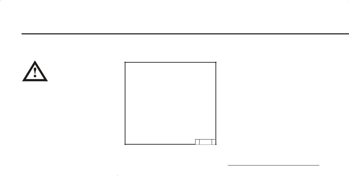
3.3.1Engine oil pressure Oil pressure light
© 25 752 1
zThe oil pressure light comes on for about 2s after switching on the system.
zThe oil pressure light must be off when the engine is running.
Oil pressure gauge
© 25 754 0
zOilpressuregaugeshowsthelubeoilpressure (minimum lube oil pressure, see chap. 9.1).
© 2005
![]()
|
3.3 |
Operation monitoring |
Operation |
||||||||||||
|
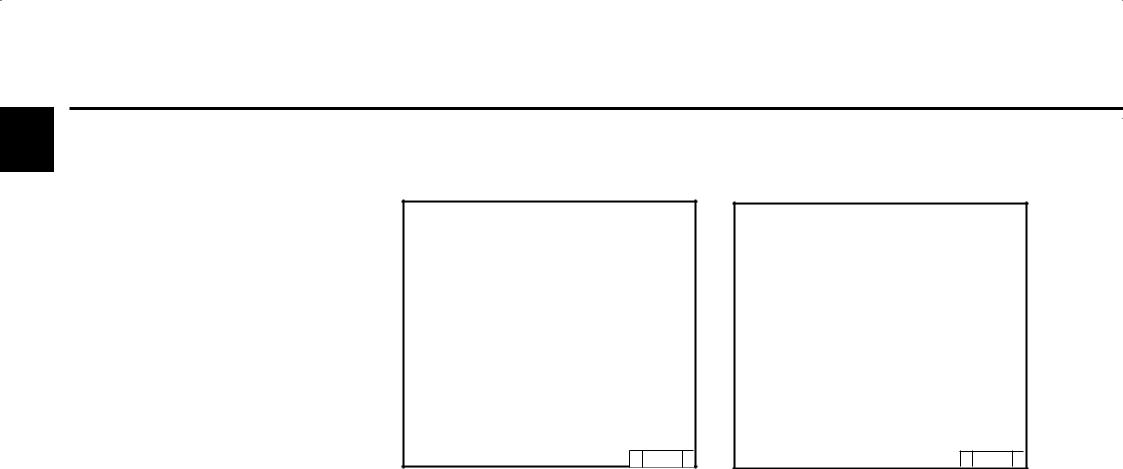
3.3.2 |
Coolant temperature |
3.3.3 Coolant level |
3 |
|||||||||||
© 26 246 0
zThe needle of the temperature display should always be in the green area, and only as an exception in the yellow/green area. If the needle rises into the orange area the engine is getting too hot. Switch off the engine and determine the cause as per fault table (see 7.1).
min
© 26 291 1
zLightoncoolantleveldisplaycomeson(contact is via float switch/ level probe if coolant level is below minimum):
Switch off the engine and determine the cause as per fault table (see 7.1).
zFunction check of coolant level: — Coolant level OK: Light goes out
© 2005
 Loading…
DEUTZ Engine TCD 2013 L04/06 4V Instruction Manual (0312 2443 en) PDF free online
CONTENTS
- General
- Engine description
- Engine type
- Company plate
- Location of company plate
- Engine number
- Cylinder numbering
- Operation side TDC 2012 L04 4V
- Engine diagrams
- Starter side TDC 2012 L04 4V
- Operation side TDC 2012 L06 4V
- Starter side TDC 2012 L06 4V
- Operation side TDC 2013 L06 4V
- Starter side TDC 2013 L06 4V
- Operation side Agri Power
- Starter side Agri Power
- Engine diagrams
- Lube oil diagram TCD 2013 L06 4V (example)
- Fuel circuit
- Fuel diagram
- Coolant circuit
- Coolant diagram
- Exhaust gas recirculation diagram
- Electrics
- Electrical cable connections for monitoring
- Operation
- Initial commisioning
- Filling engine oil
- Filling fuel
- Filling / bleeding cooling system
- Other preparations
- Starting
- Electrical starting
- Operation monitoring
- Engine oil pressure
- Coolant temperature
- Coolant level
- Lube oil level
- Shutting down
- Electrical shutdown
- Operating conditions
- Winter operation
- High ambient temperature, high altitude
- Operating substances
- Lube oil
- Quality
- Viscosity
- Fuel
- Quality
- Winter fuel
- Coolant
- Water quality for coolant
- Coolant preparation
- Cooling system preservative
- Maintenance
- Maintenance schedule
- Maintenance diagram
- Maintenance work carried out
- Care and maintenance work
- Lubrication system
- Oil change intervals
- Checking oil level, changing engine oil
- Changing oil filter insert
- Cleaning / changing oil filter (cup) fehlt
- Fuel system
- Changing fuel filter
- Cleaning / changing fuel filter (cup)
- Changing / bleeding fuel pre-filter, filter insert
- Cooling system
- Cleaning intervals
- Cleaning cooling system
- Emptying / filling / bleeding cooling system
- Combustion air filter
- Cleaning intervals
- Emptying cyclone pre-separator
- Dry air filter
- Belt drive
- Checking V-rib belt
- Changing V-rib belt
- Checking wear limit of v-rib belt fehlt
- Setting work
- Checking valve clearance, setting if necessary
- Checking control piston clearance at engine brake, setting if necessary
- Add-on parts
- Battery
- Three-phase current generator
- Transportation suspension
- Faults, causes and remedies
- Fault table
- Engine management
- Engine protection function of the electronic engine controller EMR3
- Using the diagnosis button
- Table of fault blink codes
- Engine corrosion protection
- Corrosion protection
- Technical data
- Engine and setting data
- Screw tightening torques
- Tools
- Service
Language: English
Format: PDF
Pages: 96
DEUTZ Engine TCD 2013 L04/06 4V Instruction Manual (0312 2443 en) PDF free online