- Manuals
- Brands
- EIM Manuals
- Controller
- TEC2000
- Installation & operation manual
-
Contents
-
Table of Contents
-
Troubleshooting
-
Bookmarks
Quick Links
EIM CONTROLS
T T E E C C 2 2 0 0 0 0 0 0
Installation & Operation Manual
E2K-405-0902 • Preliminary 9/02
Related Manuals for EIM TEC2000
Summary of Contents for EIM TEC2000
-
Page 1
EIM CONTROLS T T E E C C 2 2 0 0 0 0 0 0 Installation & Operation Manual E2K-405-0902 • Preliminary 9/02… -
Page 2: Table Of Contents
Table of Contents Important Notes 1.1. Purpose……………………..1-1 1.2. User Safety ……………………..1-1 Quick Start 2.1. Set Position Limits……………………2-1 2.2. Network Setup……………………. 2-5 2.3. Check Settings ……………………2-5 Installation 3.1. Preparing the Stem Nut ………………….3-1 3.2. Mechanical Installation onto the Valve………………3-2 3.3.
-
Page 3
4.4.2. View Existing Settings………………….4-8 4.5. Local Control Operation ………………….4-11 4.5.1. Multi-Port Valve Local Control Mode Operation…………..4-12 4.6. Remote/Auto Control Operation………………..4-12 4.7. Event Logger ……………………. 4-14 Customizing Actuator Settings 5.1. Entering Setup Mode…………………… 5-2 5.2. Setting Limits …………………….. 5-3 5.3. -
Page 5
Figures Figure 2-1 Declutch Lever and Handwheel………………2-2 Figure 2-2 Settings Limits – Quick Start ………………2-3 Figure 3-1 Preparing the Stem Nut ………………..3-1 Figure 3-2 Removal of STC Cover ………………..3-3 Figure 3-3 Power Terminal Connections ………………3-4 Figure 3-4 Control Terminal Connections……………… -
Page 6
Tables Table 3-1 External Power Supply ………………..3-6 Table 3-2 Internal Power Supply………………..3-6 Table 3-3 ACM Wiring Connections — Futronic (Analog Control Module) ……….. 3-8 Table 3-4 ACM Installation Connections — Controlinc (Network Control Module)……… 3-9 Table 3-5 Connecting Actuator A to Actuator B …………….3-15 Table 3-6 ARM Wiring Connections ……………….. -
Page 7: Important Notes
1. Important Notes Important Notes 1.1. Purpose This installation and operation manual explains how to install, operate, and maintain the TEC 2000 valve actuator. X WARNING: Read this manual in its entirety before installing, operating, or performing maintenance on the TEC 2000 valve actuator. X WARNING: Use caution when working on, with, or around valves and actuators.
-
Page 8: Quick Start
2. Quick Start Quick Start Quick start provides step-by-step instructions for initializing the TEC 2000 actuator. When these instructions are complete, the position limits will be set and the actuator will be ready for normal operation. NOTE: The actuator has been configured as specified by the customer and no further changes should be required.
-
Page 9: Figure 2-1 Declutch Lever And Handwheel
2. Quick Start C. Set open valve travel limit. 1. Valve Operation 1a. For Electrical Operation use the control knob to move the valve in the open direction. Proceed to Step No. 2. 1b. For Manual Operation depress the declutch lever while rotating the handwheel until the clutch is fully engaged.
-
Page 10: Figure 2-2 Settings Limits — Quick Start
2. Quick Start Figure 2-2 Settings Limits – Quick Start ELECTRICAL OPERATION Select «STOP» then SET LIMITS SETUP? select «YES,» «NO,» BEFORE «YES,» «NO,» to enter OPERATING «SETUP» mode. Use control knob to SET LIMITS CLOSE VALVE SELECT move valve to ACCEPT Switch to Switch to…
-
Page 11
2. Quick Start HANDWHEEL OPERATION Select «STOP» then SET LIMITS SETUP? select «YES,» «NO,» BEFORE «YES,» «NO,» to enter OPERATING «SETUP» mode. Declutch actuator. SET LIMITS CLOSE VALVE Rotate handwheel to SELECT ACCEPT Switch to Switch to BEFORE THEN SELECT LOCAL AND «CLOSE»… -
Page 12: Network Setup
2. Quick Start 2.2. Network Setup This is only applicable if the Controlinc Auxiliary Control Module (ACM) and the Communication Adapter Module (CAM) are installed and enabled. These instructions assume all parameters have been set with the exception of the network node address. 1.
-
Page 13: Installation
3. Installation Installation XWARNING: Failure to follow instructions for proper electrical wiring, storage, setup, and maintenace may cause serious injury, damage equipment, or void warranty XWARNING: Use caution when working on, with, or around valves and actuators. High pressures, forces, voltages, and flammable media can be present. 3.1.
-
Page 14: Mechanical Installation Onto The Valve
3. Tighten to a preload. 5/16-18UNC = 17 ft-lb, 3/8-16UNC = 50 ft lb, 5/8-11UNC = 225 ft-lb lb, or 4/4-10UNC = 400 ft lb. NOTE: Mounting screws are provided only if EIM supplied the adapter. Verify screws are though the adapter; engage a minimum of one screw diameter deep into the actuator base.
-
Page 15: Sealing Cable/Conduit Entries
3. Installation Figure 3-2 Removal of STC Cover 3.3.2. Sealing Cable/Conduit Entries Seal the cable and conduit entries in accordance with the National Electric Code or your country standard and applicable local codes. All conduit entries should be sealed against the site environment.
-
Page 16: Cable Connections
3. Installation Figure 3-3 details power terminal size and length of bare wire strip. Figure 3-3 details control terminal size and length of bare wire strip. Figure 3-3 Power Terminal Connections Terminal Size: 0.315 (M3) 0.315 Bare Wire Strip Figure 3-4 Control Terminal Connections Terminal Size: 0.375 (M4) 0.400 Bare Wire Strip…
-
Page 17: Display Backup Module (Dbm) — Optional
3. Installation Figure 3-5 Earth/Ground Connection 3.4. Display Backup Module (DBM) – Optional The DBM is a battery pack containing two 9V Lithium battery clips. This battery pack provides power to the electronics, including the real time clock for the event logger, but does not power the motor control circuits or the 24 Vdc power supply.
-
Page 18: Discrete Controlled Inputs
3. Installation 3.5. Discrete Controlled Inputs The actuator can be controlled by discrete inputs: two-wire control, three-wire control, four- wire control, and multi-port valve control. Connect the power for these discrete inputs as detailed in Table 3-1 for external power source. Table 3-2 details connections for the internal power source.
-
Page 19: Wiring The Acm
3. Installation The Futronic ACM has one 4-20mA analog input and two 4-20mA outputs. Analog Input #1 is the valve position set point. Analog Output #1 is position feedback and Analog Output # 2 is torque. The two analog outputs are used for valve position and torque feedback. The Controlinc ACM has two analog inputs and one analog output.
-
Page 20: Table 3-3 Acm Wiring Connections — Futronic (Analog Control Module)
3. Installation Table 3-3 ACM Wiring Connections — Futronic (Analog Control Module) STC Terminal Terminal Name Function Analog Input #1 (+) 4-20mA Position Set point Analog Input #1 (-) Analog Output #1 (+) 4-20mA Position Feedback Analog Output #1 (-) Analog Output #2 (+) 4-20mA Torque Feedback Analog Output #2 (-)
-
Page 21: Table 3-4 Acm Installation Connections — Controlinc (Network Control Module)
3. Installation The ARM can be installed with the Futronic ACM by stacking it on top of the Futronic ACM and connecting to the STC. See Section 3.7, Auxiliary Relay Module (ARM). Table 3-4 ACM Installation Connections — Controlinc (Network Control Module) TC Terminal Default Function Alternate Function…
-
Page 22: Analog Controlled — Power Supply Connections
3. Installation 2. All digital relay outputs are Rated for 5A @ 30 Vdc of 5A @ 250 Vac Resistive, 2A Inductive load. 3. Jumpers can be added between Terminals 8 and 10, Terminals 20 and 22, Terminals 32 and 34, Terminals 36 and 38, and Terminals 40 and 42 but are not required. 4.
-
Page 23
3. Installation 3-11 TEC 2000 Installation & Operation Manual E2K-405-0902… -
Page 24: Figure 3-9 Futronic — Analog Output With External Power Supply
3. Installation Figure 3-9 Futronic – Analog Output with External Power Supply Figure 3-10 Futronic – Analog Output with Internal Power Supply Figure 3-11 Controlinc – Analog Input with External Power Supply Figure 3-12 Controlinc – Analog Input with Internal Power Supply Figure 3-13 Controlinc –…
-
Page 25: External Variable Frequency Drive Wiring
3. Installation Figure 3-14 Controlinc – Analog Output with Internal Power Supply 3.6.3. External Variable Frequency Drive Wiring The TEC 2000 must be configured for the VFD applications at the factory. External variable frequency drive (VFD) applications require the STC shown in Figure 3-15. For the VFD applications remove the STC Cover, and wire as detailed in Figure 3-15 STC for VFD Applications .
-
Page 26: Network Controlled
3. Installation Figure 3-16 External VFD Control Wiring 3.6.4. Network Controlled For the actuator to be network controlled, a Controlinc ACM and a Communication Adapter Module (CAM) must be installed. Each CAM is required for a specific protocol and network topology, and enables the network capability.
-
Page 27: Auxiliary Relay Module (Arm) Wiring
3. Installation Table 3-5 Connecting Actuator A to Actuator B Terminal Block Function Data Port A (+) Data Port A (-) Shield Data Port B (+) Data Port B (-) Shield 3.7. Auxiliary Relay Module (ARM) Wiring The ARM can be used with the Futronic ACM or standalone. Only factory-trained technicians may install the ARM.
-
Page 28: Remote Display Module (Rdm) Connection To The Actuator — Optional
3. Installation Figure 3-17 ARM Wiring Connections ARM Wiring Terminals 39-44 3.8. Remote Display Module (RDM) Connection to the Actuator – Optional Connect the RDM to the actuator as shown in Figure 3-18 and in accordance with Section 3.8.1, 24Vdc Power Source, or Section 3.8.2, 115/230Vac Power Source, depending on the power source.
-
Page 29: 24Vdc Power Source
3. Installation 3.8.1. 24Vdc Power Source If the RDM is to receive power from the actuator, connect cable type Belden 8723 or equivalent as detailed in Table 3-7. The cable distance is limited to 1,200 feet (366 meters). NOTE: By using two cables, Belden 8719 or equivalent for power and Belden 9841 or equivalent for RS-485 communication, the distance limitation is increased to 4000 feet (1200 meters).
-
Page 30: Two Rdms (One 24Vdc And One 115/208/220/230 Vac Power Source)
3. Installation 3.8.3. Two RDMs (one 24Vdc and one 115/208/220/230 Vac power source) To use two RDMs with one actuator, connect as detailed in Table 3-9. Table 3-9 Two RDMs Connected to the Actuator RDM Terminal Function TEC 2000 Cable Type- Block Number Terminal Block Belden or…
-
Page 31: Operation
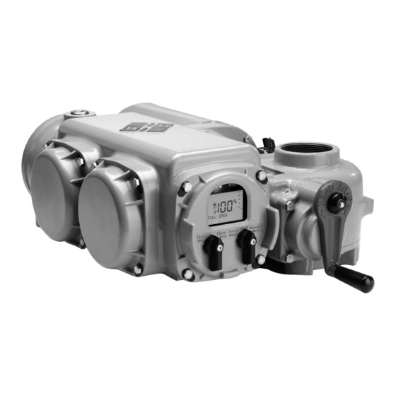
4. Operation Operation Figure 4-1 TEC 2000 Controller Local Display Module Remote Display Module Clicker 4.1. Local Display Module (LDM) The Local Display module consists of the following as shown in Figure 4-2: ?? Graphics Display ?? Message Center ?? Control Knob and Selector Knob ?? Three LEDs TEC 2000 Installation &…
-
Page 32: Graphics Display And Message Center
4. Operation Figure 4-2 LDM LEDs Graphic Display Message Center Selector Control Knob Knobs 4.1.1. Graphics Display and Message Center The graphics display displays the mode of operation, valve status, position, torque, and alarm symbols. The message center displays actuator setup selections, data entry feedback, and alarm messages.
-
Page 33: Leds
4. Operation Table 4-1 LDM Rotating Knobs Knob Rotation Direction Function Results Control Spring return to center Neutral Completes YES or NO entry Position cycle. Exception: when knob is held for continuous data entry updates. Clockwise (CLOSE) Accepts the displayed question or data entry.
-
Page 34: Figure 4-3 Normal Display
4. Operation Figure 4-3 Normal Display The valve has stopped and is 36% opened. The yellow LED is ON and the message center is clear. Table 4-2 Normal Display Functions Display Functions Valve Message Activity Center LEDs Position Bar Percent Top Line Graph Open “XX%”…
-
Page 35: Multi-Port Valve Status Display Functions
4. Operation 4.1.5. Multi-Port Valve Status Display Functions Table 4-3 details the various activities and how each is displayed when operating in the “MULTI-PORT VALVE” mode. Table 4-3 «Multi-port Valve Status» Display Functions Display Functions Valve Position LEDs Position Bar Graph Yellow Green Port A…
-
Page 36: Infrared Controller (Irc) — «Clicker
4. Operation Table 4-4 RDM and LDM Operation Priority Mode of Selector Switch Position Selector Switch Position Selector Switch Position Operation RDM #1 RDM#2 STOP At least one module must have the selector switch in the STOP position. LOCAL At least one module must have the selector switch in the LOCAL position and none have the selector switch in the STOP position.
-
Page 37: Initializing The Actuator
4. Operation For the “Clicker” to control the actuator: 1. Enter “SETUP” mode using the control knobs as defined in Section 5.1, Entering Setup Mode. 2. Select “LOCAL IrDA PORT” for control mode under Valve Control Setup. See Section 5.6.2, Valve Control Setup. 3.
-
Page 38: View Existing Settings
4. Operation 4.4.2. View Existing Settings Unless otherwise specified at the time the order is placed, the TEC 2000 actuator is shipped with the following default configuration settings. TEC 2000 Installation & Operation Manual E2K-405-0902…
-
Page 39: Table 4-5 Default Configuration Settings
4. Operation Table 4-5 Default Configuration Settings Basic Actuator Functions Valve Control Discrete Inputs Discrete Outputs Inhibit and ESD (Relays 1 (ACM Solid State (ARM Relays 9 thru 5) Outputs 6 thru
 thru 12) Mode =3-Wire DI#1 = Active on RO#1 = LSO SSO#6 = VFD RO#9 = Lost…
 -
Page 40
4. Operation Two-Speed Timer Default Configuration Close Open Anti-Water Hammer Mode = ON Mode = ON Mode = ON Start Position = 30% Start Position = 70% Start Position = 10% Stop Position = 1% Stop Position = 99% Pulse ON time = 3.5 Sec Pulse ON time = 3.5 Sec Pulse ON time = 3.5 Sec Pulse OFF time = 5.0 Sec… -
Page 41: Local Control Operation
4. Operation Figure 4-5 View Settings DISPLAY VALVE TWO-SPEED SETTINGS? CONTROL See Figure 5-6 TIMER See Figure 5-12 SETUP? SETUP? Go to next display see Figure 5-1 DISCRETE ANALOG INPUT See Figure 5-9 SETUP? See Figure 5-13 SETUP? DISCRETE NETWORK OUTPUT See Figure 5-10 SETUP?
-
Page 42: Multi-Port Valve Local Control Mode Operation
4. Operation Local Momentary Mode – Seal-ins Active 3. Place the control knob in either the OPEN or CLOSE position. Momentarily hold for 0.5 seconds and release. The actuator will move in the open or close direction to the end of travel.
-
Page 43
The local RS-485 port control mode allows the actuator to be controlled via the RS-485 port. Any device with a RS-485 port and application software to support the EIM proprietary protocol can be used. The remote device is a slave to the CCM and has a slave address of 4. -
Page 44: Event Logger
4. Operation 4.7. Event Logger 4-14 TEC 2000 Installation & Operation Manual E2K-405-0902…
-
Page 45: Customizing Actuator Settings
5. Customizing Actuator Settings Customizing Actuator Settings 5.1. Entering Setup Mode The “SETUP” mode must be entered to modify any configuration settings. 1. Place the selector knob in the STOP position. Setup may be performed at any one location; i.e. at the LDM or any RDM that is connected. NOTE: STOP button on the Clicker only stops a moving valve.
-
Page 46: Setting Limits
5. Customizing Actuator Settings Figure 5-1 Setup SETUP? CHANGE DISPLAY DISPLAY? See Section 5-3 SETTINGS? See Figure 4-5 EXIT SETUP and revert to normal display DISPLAY UNIT DISPLAY PARAMETERS? DIAGNOSTICS? See Figure 6-1 See Figure 5-3 BACK NEXT CHANGE EXIT? EXIT SETUP SETTINGS? See Figure 5-4…
-
Page 47
5. Customizing Actuator Settings 3. If English is not desired, answer “YES” to “CHANGE LANGUAGE?” and “DISPLAY OTHER?” will appear. The user may change any of the words being displayed on the message center by downloading an alternate language. “ADJUST CONTRAST?” will appear. -
Page 48: Transferring File Parameters
The user may transfer certain files to or from the TEC 2000 using a computer with an IrDA port or RS485 port. This requires EIM TecLinc software for displaying, editing, storing, and printing these files. All user instructions for file transfer process are displayed on the external computer screen.
-
Page 49: Computer Requirements
5. Customizing Actuator Settings Files that may be transferred from the TEC 2000: ?? Diagnostics ?? Unit Parameters ?? User Settings ?? Language ?? Factory Settings ?? Event Log Files that may be transferred to the TEC 2000: ?? Language ?? User Settings — Includes all items under CHANGE SETTINGS except calibration parameters such as display contrast, and analog input or output calibration ?? Factory Settings — Includes all items under FACTORY SETUP;…
-
Page 50: Displaying Unit Parameters
1. Load the applicable software onto the hard drive. See Section 5.4.1, Computer Requirements. NOTE: TecLinc software can be downloaded at www.eim-co.com. If web access is not available, contact your local EIM distributor or EIM directly and request a TecLinc CD. 2. Follow instructions provided with the software. 5.5. Displaying Unit Parameters The user may view information on the actuator parameters as follows: 1.
-
Page 51: Change Settings
5. Customizing Actuator Settings 5.6. Change Settings 1. Enter “SETUP” mode and use the selector knob (NEXT) to scroll to “CHANGE DISPLAY SETTINGS?”. Answer “YES.” See Section 5.1, Entering Setup Mode. 2. Enter passcode. NOTE: A passcode must be entered to change settings. 3.
-
Page 52: Figure 5-1 Setup
5. Customizing Actuator Settings Figure 5-4 Change Settings Displayed only if VALVE ANALOG ACM installed and From PASSCODE CONTROL See Figure 5-6 SETUP? ANALOG control Figure 5-5 SETUP? is enabled. See Figure 5-13 Displayed only if SET VALVE NETWORK ACM installed and See Figures TRAVEL SETUP?
-
Page 53: Passcode Entry
5. Customizing Actuator Settings 5.6.1. Passcode Entry The actuator is shipped with “000” as a passcode. To change the passcode see Section 5.6.11, Passcode Setup. To enter the passcode: 1. At the “CHANGE SETTINGS?” prompt answer “YES.” “ACCEPT PASSCODE CHARACTER 1? X” will appear. “X” will be flashing. “X” is the first “left most” character in the passcode.
-
Page 54: Figure 5-6 Valve Control Setup
5. Customizing Actuator Settings Figure 5-6 Valve Control Setup Associated choices are listed below each setting. BACK NEXT CLOSE POSITION CONTROL VALVE SEAT DIRECTION MODE CONTROL CLOCKWISE THREE-WIRE SETUP? TORQUE SEAT Goto next display TWO-WIRE CLOSE DIRECTION see Figure 5-4 THREE-WIRE COUNTERCLOCKWISE FOUR-WIRE…
-
Page 55: Set Valve Travel Limits
5. Customizing Actuator Settings 5.6.3. Set Valve Travel Limits For all control modes except multi-port valve 1. If the close limit is acceptable, answer “YES.” If not rotate the selector knob to LOCAL. Close valve to desired limit, rotate selector knob to STOP, and answer YES. 2.
-
Page 56
5. Customizing Actuator Settings 5. If an external synchronization switch is wired to Digital Input #5 (close inhibit), select “MULTI-PORT SYNC ON?” and answer “YES.” If not, select “MULTI-PORT SYNC OFF?” and answer “YES.” Normal Operation Mode — Set Limits with Handwheel Operation ACCEPT ACCEPT SAVE… -
Page 57: Discrete Input Setup
5. Customizing Actuator Settings Figure 5-8 Set Valve Travel Limits for Multi-port Valve Control Mode ACCEPT ACCEPT ACCEPT SET VALVE VALVE VALVE VALVE TRAVEL PORT A PORT B PORT C LIMITS?? LIMIT? LIMIT? LIMIT? LOCAL LOCAL LOCAL Goto next display see Figure 5-4 MOVE VALVE MOVE VALVE…
-
Page 58: Discrete Output Setup
5. Customizing Actuator Settings Figure 5-9 Discrete Input Setup Configuration of discrete inputs are shown below. BACK NEXT DI #2 ACTIVE DI #3 ACTIVE DI #1 ACTIVE DISCRETE ON OPEN ON CLOSED ON CLOSED INPUT CONTACT CONTACT CONTACT SETUP? DI #1 ACTIVE ON DI #2 ACTIVE ON DI #3 ACTIVE ON Goto next display…
-
Page 59: Table 5-2 Relay Outputs #1 Through #5 Configuration
5. Customizing Actuator Settings Table 5-2 Relay Outputs #1 through #5 Configuration Relay Default Configurable Configure Default Configure Function Function N.O./N.C. Setting Flashing RO#1 Table 5-3 N.O. Relay Output Valve full OPEN Function List RO#2 N.O. Table 5-3 Relay Output Valve full Function List CLOSE…
-
Page 60: Table 5-3 Relay Output Function List
5. Customizing Actuator Settings Table 5-3 Relay Output Function List Function List LSO (Open LOW MAIN BATTERY OVER TORQUE (Open or CLOSE INHIBIT limit) Close) LSC (Close LOCAL VALVE STALL LOCAL ESD limit) STOP (SS OFF) VALVE DRIFT (MOVED BY ESD ACTIVE (Intermediate HANDWHEEL)
-
Page 61: Figure 5-10 Discrete Output Setup
5. Customizing Actuator Settings Figure 5-10 Discrete Output Setup BACK NEXT RELAY #1 RELAY #1 RELAY #1 DISCRETE N.O. CONTINUOUS OUTPUT SETUP? See Function List N.C. FLASHING Goto next display see Figure 5-4 RELAY #2 LSC RELAY #2 N.O. RELAY #2 RELAY #3 CONTINUOUS See Function List…
-
Page 62: Table 5-5 Relay Outputs #9 Through #12 Configuration
5. Customizing Actuator Settings Relays #9 through #12 are the auxiliary relays when the Auxiliary Relay Module (ARM) is installed. To configure these relay outputs, follow Step No.1 through No. 3 listed above. See Table 5-5. NOTE: The ARM cannot be added when the Controlinc ACM is installed. Table 5-5 Relay Outputs #9 through #12 Configuration Relay Default…
-
Page 63: Inhibit And Esd Setup
5. Customizing Actuator Settings 5.6.6. Inhibit and ESD Setup 1. At the “INHIBIT AND ESD SETUP?” prompt answer “YES.” 2. Use the selector knob (NEXT/BACK) to review the settings for Control Inhibits and Emergency Shut Down. 3. Use the control knob (NO) to select either ON or OFF for each setting; then answer “YES.” Figure 5-11 details each setting.
-
Page 64: Two-Speed Timer Setup
5. Customizing Actuator Settings 5.6.7. Two-Speed Timer Setup The two-speed timers can be configured for the actuator to be controlled with different opening and closing times. All configured timers are active in the LOCAL and REMOTE modes. NOTE: All three timers, close, open, and anti-water hammer, can operate at the same time. If two timer ranges overlap, the anti-water hammer timer overrides all timers.
-
Page 65: Figure 5-13-1 Analog Setup
5. Customizing Actuator Settings To calibrate analog outputs, the user must connect a calibrated precision 4-20mA current meter to Terminals 27(+) and 28(-) for AO#1 or Terminals 29(+) and 30(-) for AO#2 Figure 5-13-1 Analog Setup NOTE: The actuator senses that the Futronic ACM is installed and adjusts the display sequence to display only one input ANALOG CONTROL…
-
Page 66
5. Customizing Actuator Settings Figure 5-13-2 Analog Setup Continued From last display in Figure 5-13-1 IS EXTERNAL CALIBRATE CALIBRATE ACCEPT 4MA AO#1 4-20MA? 4MA? METER SETTING? CONNECTED? INCREASE SETTING 0.005MA? DECREASE SETTING 0.005MA? CALIBRATE IS EXTERNAL ACCEPT 20MA 20MA? METER SETTING? CONNECTED? INCREASE… -
Page 67
5. Customizing Actuator Settings Figure 5-13-3 Analog Setup Continued From last display in Figure 5-13-2 IS EXTERNAL CALIBRATE CALIBRATE ACCEPT 4MA METER AO#2 4-20MA? 4MA? SETTING? CONNECTED? INCREASE SETTING 0.005MA? DECREASE SETTING 0.005MA? CALIBRATE IS EXTERNAL ACCEPT 20MA 20MA? METER SETTING? CONNECTED? INCREASE… -
Page 68: Network Setup (Cam And Controlinc Acm Required)
5. Customizing Actuator Settings 5.6.9. Network Setup (CAM and Controlinc ACM Required) NOTE: Only displayed/applicable if the Communication Adapter Module (CAM) and the ControIinc ACM are installed, and the network control is enabled. See Section 5.6.2, Valve Control Setup. 1. At the “NETWORK SETUP?” prompt, answer “YES.” 2.
-
Page 69: Figure 5-14-1 Network Setup
5. Customizing Actuator Settings Figure 5-14-1 Network Setup NOTE: The actuator senses that the Controlinc ACM is installed and adjusts the display sequence to display only one output NETWORK NETWORK REPONSE SETUP? NODE DELAY 008 ADDRESS 001 Goto next display 001-254 001-255 mS see Figure 5-4…
-
Page 70: Tag Name Setup
5. Customizing Actuator Settings Figure 5-14-2 – Network Setup Continued From last display in Figure 5-14-1 CALIBRATE CALIBRATE IS EXTERNAL ACCEPT 4MA METER AO#1 4-20MA? 4MA? SETTING? CONNECTED? INCREASE SETTING 0.005MA? DECREASE SETTING 0.005MA? CALIBRATE IS EXTERNAL ACCEPT 20MA 20MA? METER SETTING? CONNECTED?
-
Page 71: Passcode Setup
5. Customizing Actuator Settings Figure 5-15 Tag Name Setup TAG NAME ACCEPT? ACCEPT? ACCEPT? Continue this process SETUP? MOV-123456 for 16 characters Goto next display sp, -, 0-9, A-Z sp, -, 0-9, A-Z sp, -, 0-9, A-Z see Figure 5-4 Goto next display see Figure 5-4 5.6.11.
-
Page 72: Troubleshooting
6. Troubleshooting Troubleshooting XCAUTION: This actuator is non-intrusive. Do not open the control compartment on the actuator unless absoutely necessary. It was sealed in dry-clean conditions in the factory and entry into this compartment should not be necessary. Unauthorized entry could void the warranty.
-
Page 73
6. Troubleshooting Handwheel will not Handwheel shaft bearing Repair or replace as necessary operate valve assembly malfunction Stripped Gearing Replace as necessary PS shifter position or Replace PS shifter or replace gear(s) malfunction Broken Handwheel Shaft Repair or replace as necessary Broken valve stem of stripped Repair or replace as necessary stem nut… -
Page 74: Display Diagnostics
6. Troubleshooting 6.2. Display Diagnostics Displaying diagnostics retrieves historical data that is stored in the actuator’s memory. This aids in troubleshooting. 1. At the “DISPLAY DIAGNOSTICS?” prompt, answer “YES.” 2. Use the selector knob (NEXT/BACK) to review the settings. See Figure 6-1. NOTE: When the “SET LIMITS BEFORE OPERATING”…
-
Page 75: Figure 6-1 Display Diagnostic
6. Troubleshooting Figure 6-1 Display Diagnostic DISPLAY DISPLAY DIAGNOSTICS? ALARM LOG? See Figure 6-2 Goto next display see Figure 5-1 DISPLAY TORQUE See Figure 6-3 PROFILE? DISPLAY TORQUE See Section 6.2.3 ARCHIVE? DISPLAY OPERATE See Figure 6-4 LOG? DISPLAY OPERATE See Figure 6-5 ARCHIVE? DISPLAY…
-
Page 76: Display Alarm Log
6. Troubleshooting EFM MONITOR OPEN INHIBIT OPEN TORQUE_% CLOSE INHIBIT CLOSE TORQUE_% LOCAL ESD VALVE STALLED REMOTE ESD VALVE DRIFT LOST AIN1 SIGNAL POWER FAIL ACTUATOR FAIL LOST PHASE SETUP ERROR MOTOR OVERLOAD SET LIMITS BEFORE OPERATING NOTE: When the “SET LIMITS BEFORE OPERATING” alarm is displayed, no other alarms will be displayed until the limits are set.
-
Page 77: Display Torque Profile
6. Troubleshooting 6.2.2. Display Torque Profile Torque profile is data on the last stroke. Torque data is recorded at 10% intervals of valve travel and is displayed for both open and close directions. Pullout torque is peak torque recorded in the open direction from 0 to 9% while unseating the valve. 1.
-
Page 78: Display Operation Archive
6. Troubleshooting 1. At the “DISPLAY OPERATE LOG?” prompt, answer “YES.” 2. Use the control knob (YES) to review the operate log Motor starts value is the number of times the motor has been started. The strokes value displayed is the number of full strokes from limit to limit. Stroke time can be measured as follows: 1.
-
Page 79: Display Hardware
6. Troubleshooting From last display in Figure 6-4 STROKES MOTOR MOTOR RUN DISPLAY STARTS 999,999,999 TIME OPERATE 999,999,999 999,999,999 ARCHIVE? HOURS Goto next display see Figure 6-1 6.2.6. Display Hardware This display reports the status of the modules and can identify which module is at fault if a problem exists with the actuator.
-
Page 80
6. Troubleshooting NORMAL NORMAL LOST LINK FAILED FAILED APD MODULE INSIDE CENTRAL DISPLAY NORMAL CONTROL TEMPERATURE HARDWARE? = 45C NORMAL Goto next display see Figure 6-1 NORMAL NORMAL NORMAL NOT CONFIGURED NOT CONFIGURED LOST LINK LOST LINK LOST LINK FAILED FAILED FAILED REMOTE… -
Page 81: Maintenance
1. After actuator has been located in the field and valve position has been determined, remove ½ NPT plug from the highest ½ NPT vent location on the gearbox. 2. Replace with Relief Vent Fitting Part No. 83385. See EIM Outline Drawing No. XXX for possible vent locations 7.4.
-
Page 82: Battery Replacement — «Clicker
7. Maintenance Figure 7-1 Fuses in the STC 7.5. Battery Replacement – “Clicker” 1. Insert a coin in the slot on the right hand corner of the key ring end and twist. 2. Slide battery to remove 3. Replace battery Panasonic Part No. CR2031 or equal. TEC 2000 Installation &…
-
Page 83: Regulatory Information
8. Regulatory Information Regulatory Information Class I, II, III Div. 1 Groups B, C, D, E, F, G T4 & T4A @ Ta 60°C, Type 6P Class I, II, III Div. 1 Groups B, C, D, E, F, G T4 & T4A @ Ta 60°C, Type 6P EEx d IIB T4 &…
-
Page 84
Appendix A Appendix A TEC 2000 Assembly Drawing — TBD EIM E796 document (1 column page 3) “Need to modify referenced M2CP drawing to show TEC 2000 enclosure…” TEC 2000 Installation & Operation Manual E2K-405-0902…
 thru 12) Mode =3-Wire DI#1 = Active on RO#1 = LSO SSO#6 = VFD RO#9 = Lost…
 Только для стран Северной Америки Данный электропривод является следующим поколением неинтрузивного привода TEC2000 Прочная и компактная конструкция, широко применяемая в клапанах для морской, нефтегазовой, химической, энергетической отраслей, а также в системах водоснабжения и канализации.
Подробнее…
Особенности
- Please refer to documentation for product features.
Технические характеристики
Документация и чертежи
Что такое TEC-2000
Tec-2000 Engine Flush-это уникальная композиция растворителей и высокоэффективные препараты с смазочными свойствами. и немногочисленные препараты, в которых отказались от хлорированных углеводородов — это означает отсутствие вредных паров при работе препарата и более чистой окружающей среды.TEC-2000
Флеш признан одним из самых эффективных и действенных препаратов для очистка внутренней части двигателя. Он очень прост в использовании в любых условиях. Формула отличная репутация среди клиентов, профессионально занимающихся автомобильным рынком.
Электроприводы EIM
![]()
История EIM
На протяжении более 60 лет EIM ™ производит высококачественные электрические приводы. EIM гордится тем, что разработала и запатентовала несколько базовых проектных решений, которые сейчас используются в производстве приводов клапанов. EIM продолжает вводить новшества, предлагая надежные приводы и клапаны.
EIM. Электрические приводы
Электрические приводы разработаны для обеспечения оптимальной производительности в наиболее сложных условиях эксплуатации для отсечных и регулирующих клапанов.
Приводы EIM серии 2000 и TEC2000™ эксплуатируются уже более 60 лет по всему миру и доказали свою надежность и долговечность.
- Для многооборотных моделей максимальный крутящий момент до 27116 Нм. Скорость вращения вала от 3 до 240 оборотов в минуту.
- Для четвертьоборотных моделей максимальный крутящий момент до 370,000 Нм. Время срабатывания от 5 до 900 секунд.
- Приводы с линейными модулями
- Стандартное исполнение корпуса соответствует SIRA/ATEX, FM CSA, ГОСТ.
- Модульная конструкция — более 60% компонентов унифицированы. Управляющие модули одинаковы для многооборотных и четвертьоборотных исполнений.
- Ручной дублер
- Поддержка различных полевых шин — Profibus, Foundation Fieldbus, Device Net и Modbus RTU.
Электроприводы серии TEC2000 ™
Электроприводы TEC2000 — интеллектуальные приводы с «непроникающей» настройкой от «EIM controls» ТЕС2000® (Total Electronic Control) сочетают в себе проверенную временем надежность механической конструкции и микропроцессорное управление. Для настройки привода с арматурой не требуется действий по вскрытию крышек корпуса.
- Микропроцессорное управление обеспечивает точное позиционирование привода засчет использования датчиков Холла.
- Местные элементы управления не имеют воздействия на датчики Холла.
- Самый большой и легко читаемый ЖК дисплей в промышленности.
- Полнофункциональный удаленный дисплей может быть установлен на расстоянии до 1200 м.
- Отдельный клеммный отсек и легкодоступные предохранители.
С подробной информацией и техническими данными Вы можете ознакомиться в разделе «Документы»
Для подбора подходящего для Вас привода просим заполнить опросные листы в разделе «Документы» и отправить их нам по электронной почте, либо связаться с нашими техническими специалистами по тел. в Санкт-Петербурге (812)677-2303
Электроприводы серии Series2000 ™
Электроприводы ранее были реализованы с модульным блоком управления МСР (Modular Control Package), который легко разбирается и обеспечивает быстрое обслуживание, замену или модернизацию. Позднее блок был заменен на более современный М2СР, раскрывающий новые возможности, такие как аналоговое регулирование положения (система EIM Futronic). Конструкция аналогичная, как у TEC2000, отличие в блоке управления. Блок управления М2СР имеет модульную конструкцию и комплектуется под требования заказчика.
Для подбора подходящего для Вас привода просим заполнить опросные листы в разделе «Документы» и отправить нам их по электронной почте, либо связаться с нашими техническими специалистами по тел. в Санкт-Петербурге (812)677-2303
![]()
When we created the TEC2000 we didn’t reinvent the wheel. Instead of devising a completely new actuator, we simply equipped our well-established Series 2000 actuator with all the features needed to offer Total Electronic Control (TEC) in a truly non-intrusive package.
Click Here To Download:
•Brochure: EIM TEC2000
•Brochure: EIM TEC2000 Engineering And Controls
When we created the TEC2000 we didn’t reinvent the wheel. Instead of devising a completely new actuator, we simply equipped our well-established Series 2000 actuator with all the features needed to offer Total Electronic Control (TEC) in a truly non-intrusive package.
This means that with the TEC2000, you get the latest standards of control and performance coupled with power transmission technology that has a 30-year history of reliability in thousands of installations worldwide. The Series 2000 heritage ensures that the TEC2000 is an electronic actuator that’s built for hard work and easy maintenance.
TEC2000 provides freedom to choose from any of three Tri-Set configuration setup methods:
- Control knobs on either the Local Display Module (LDM) or on the optional Remote Display Module (RDM), which can be mounted up to 1200 meters (4000 ft) away from the actuator.
- PC or PDA via RS-485 link to the actuator, or via the IrDA port, utilizing EIM’s TecLinc Windows®-based software.*
- EIM’s optional keychain «Clicker» device. The «Clicker,» an IrDA controller, has four buttons that correspond to the Yes, No, Back and Next functions of the local control knobs. The entire actuator configuration process can be completed using this compact tool. (Clicker not available in Japan or England).
Click Here To Download:
•Brochure: EIM TEC2000
•Brochure: EIM TEC2000 Engineering And Controls