-
Contents
-
Table of Contents
-
Bookmarks
Quick Links
ASM 340
Leak detector
Operating Instructions
EN
Summary of Contents for Pfeiffer ASM 340
-
Page 1
ASM 340 Leak detector Operating Instructions… -
Page 2: Table Of Contents
Table of contents Table of contents About this manual ……….4 1.1 Validity.
-
Page 3
Table of contents 7.1.4 Erasing ……….30 7.1.5 Viewing a recording. -
Page 4: About This Manual
About this manual Validity This operating manual is for customers of Pfeiffer Vacuum. It describes the functioning of the designated product and provides the most important information for safe use of the unit. The description follows applicable EU guidelines. All information provided in this operating manual refers to the current state of the product’s development.
-
Page 5: Conventions
About this manual Conventions 1.2.1 Safety instructions Operating manual safety instructions Pfeiffer Vacuum are based on the UL, CSA, ANSI Z-535, SEMI S2, ISO 3864 and DIN 4844 certification standards. This document de- scribes the following information and danger levels: DANGER Imminent danger Indicates an imminent hazardous situation that will result in death or serious injury.
-
Page 6: Pictographs
About this manual 1.2.2 Pictographs Prohibition of an action or activity in connection with a source of danger, the disregarding of which may result in serious accidents Warning of a displayed source of danger in connection with operation of the unit or equipment Command to perform an action or task associated with a source of dan- ger, the disregarding of which may result in serious accidents 1.2.3…
-
Page 7
About this manual Quality: certifies that the product has been certi- fied compliant with quality control upon leaving the factory. Indicates whether the Bluetooth, Wi-Fi or Ether- HLD1302577 — RS232 net options have been installed on the products, Bluethooth MAC address and their MAC addresses. -
Page 8: Safety
Safety Safety Safety precautions Obligation to inform Any person responsible for installing, using or maintaining the product must first read the security instructions in this operating manual and comply with them. It is the operating customer’s responsibility to protect all operators against the dan- gers associated with the product, with the media pumped and with the entire instal- lation.
-
Page 9: Protective Equipment
Safety NOTICE Wet Model: Filling with oil Oil must be added to the primary pump before the detector is switched on. The potential hazards for a leak detector involve electricity, the tracer gas, the pres- surised nitrogen supply and the lubricant (for the Wet models). ●…
-
Page 10: Proper Use
Safety Proper use NOTICE EC conformity The manufacturer’s declaration of conformity becomes invalid if the operator modifies the original product or installs additional components. Following installation into a plant and before commissioning, the operator must check the entire system for compliance with the valid EU directives and reassess it accor- dingly.
-
Page 11: Transport And Storage
Transport and storage Transport and storage Upon delivery, check that the product has not been damaged during transport. If the product is damaged, contact the carrier and notify the manufacturer. In all situations we recommend: keeping the product in its original packaging so it stays as clean as it was when dis- patched by us.
-
Page 12: Storage
Transport and storage Before moving a detector, make sure that the covers are properly attached: the front cover cancels 3 fixing screws for the rear cover (out of the 5 screws in total): make sure that these 3 screws are in place and properly tightened. …
-
Page 13: Product Description
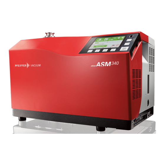
● 1 protective cover 4.1.2 Variants The ASM 340 leak detectors are particularly suitable in Industry for vacuum and sniffing leak detection, in various applications from maintenance to small production applica- tions. Easy operation, robustness, ultra fast response time, are among the outstanding features of these compact multipurpose units.
-
Page 14: Connection Interface
Test method The test method is chosen depending on the part to be tested. For more information about leak detection test methods, see Leak detector compendi- um on the website www.pfeiffer-vacuum.com. 4.3.1 Hard vacuum test ● Part that can be connected to pipe and placed under a vacuum ●…
-
Page 15: Sniffing Test
Product description At the time of spraying, the leak rate does not appear instantly. There is a response time which depends on the volume V to be tested and on the tracer gas pumping speed S of the system at part’s inlet, according to the ratio: T = V/S (T in seconds, V in litres, S in l/s).
-
Page 16: Installation
Installation Installation Prerequisites for optimising measurement To optimise pumping and measurement speed: ● Use pipe with a diameter equal to the diameter of the detector’s inlet. The pipes should be as short as possible and completely sealed. ● Do not use plastic hoses such as compressed air pipes. ●…
-
Page 17: Filling With Oil (Wet Model Only)
Installation 5.3.1 Storing the lifting handles One the detector has been installed, the handles can be removed and stored in the back of the detector or used to place the control panel on a work surface. ● 5-mm Allen key. Tools required Fig.
-
Page 18: Connecting The Purge Circuit
Installation Make sure that the detector is off (circuit breaker at 0, the control panel screen is off) and in a horizontal position. Open the cover. Remove the oil fill cap (1) from the rotary vane pump (2). …
-
Page 19: Connection To The Mains Power Supply
Installation Connection to the mains power supply WARNING Risk of electromagnetic disturbance The product’s EMC rating is obtained on the understanding that it is installed in compli- ance with EMC rules. Use sheathed links and connections for interfaces in environments that produce dis- turbance.
-
Page 20: Connecting The Part/Installation To Be Tested
Installation Connecting the part/installation to be tested NOTICE Limit of operation Make sure that the parts or chambers connected to the inlet of our products withstand a negative pressure of 1 · 10 hPa in relation to atmospheric pressure. ●…
-
Page 21: Operation
Operation Operation Control panel It is interfaced with the detector and is used to: – display information about the test – access the available functions – setting of the detector’s parameters. For a screenshot, set a function key to [Screen Copy] (see 7.7.2). 6.1.1 Description START…
-
Page 22: Contrast — Brightness — Screen Saver
Operation Keys for setting the values Moving to the next function/screen/parameter Return to the previous display Return to the previous display and confirm the changes made Return to the previous display without confirming the changes made Deleting the selected file Set point setting 1 Exponent setting 2 Mantissa unit setting…
-
Page 23: Standard» Screen
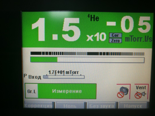
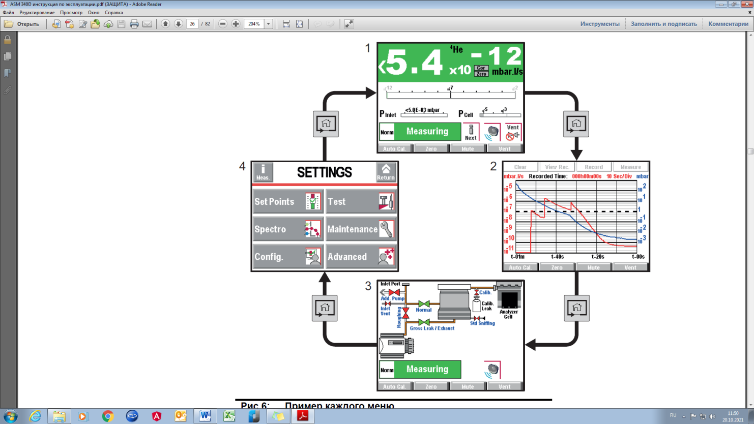
Operation Fig. 6: Example of each screen 1 «Standard» screen (home) Information about the current test 2 «Graph» screen Monitoring and recording the leak rate and/or the inlet pressure 3 «Vacuum circuit» screen Vacuum circuit of the detector and the status of the valves 4 «Settings»…
-
Page 24: Settings» Screen
Operation Mute function indicator Air inlet function indicator Cell pressure bargraph display Leak detector unit Leak rate correction function indicator 10 Zero function indicator 11 Detector inlet pressure display (unit consistent with the leak rate unit) 12 Tracer gas ( He or H A password can be used to lock access to the «Settings»…
-
Page 25: Prerequisites To Use
Operation 6.1.7 «Vacuum circuit» screen Vacuum circuit of the detector and the status of the valves. The vacuum circuit varies depending on the status of the valves, but does not make it possible to manage the valves. Fig. 7: Example of a vacuum circuit Red valve Valve closed Green valve…
-
Page 26: Switching The Detector On
Operation NOTICE Risk of seizing Never move the detector while it is in use, even if it is placed on a trolley. Before each switching on: All models Become familiar with the safety instructions (see 2). Remove the cover before using the product. …
-
Page 27: Monitoring Operation
Operation The test can also be started using a remote control (accessory): see Remote con- trol Operating instructions. Select the ’sniffing’ test method (see 7.4.1). Sniffing test With the leak detector in Stand-by mode, connect the sniffing probe (accessory) to the provided connector ( ) and select Standard or Smart probe model (see 7.4.4).
-
Page 28: Advanced Settings
Advanced settings Advanced settings «Graph» screen Access the «Graph» screen by pressing 7.1.1 Description Monitoring and recording the leak rate and/or the inlet pressure. Fig. 10: «Graph» screen 1 Deleting/Viewing/Recording a plot 2 Plot of the tracer gas leak rate (in red) 3 Scale of the tracer gas leak rate (in red) 4 Time scale 5 Inlet pressure scale (in blue)
-
Page 29: Recording
Advanced settings Example: leak rate = 5·10 Pa·m /s (5·10 mbar·l/s) ● automatic scale 2 decades: scale from 1·10 to 1·10 Pa·m (1·10 to 1·10 mbar·l/s) ● automatic scale 4 decades: scale from 1·10 to 1·10 Pa·m (1·10 to 1·10 mbar·l/s) …
-
Page 30: Erasing
Advanced settings 7.1.4 Erasing Display the «Graph» screen (Fig. 10) (see 7.1.1). Current window Press [Clear] (ref. 1) and validate the message. Clearing the current window does not delete the current recording or recordings already made. Display the «Graph» screen (Fig. 10). Recording …
-
Page 31
Advanced settings Set the area to be reduced (ref. 1 then ref. 2 Fig. 14): return to the original graph. Fig. 14: Return to the original graph Exact measurement of a point only available on a recording. Measurement Fig. 15: Example of the recording of a point 1 Modifying the leak rate and inlet pressure scales 2 Point selected … -
Page 32: Saving A Recording
Advanced settings 7.1.6 Saving a recording This function is used to save the most recent recording on a SD card to be played back/ analysed later on a PC. Saving is not automatic. It is possible to save a screenshot of the recording (.bmp) or to generate a file (.txt) with all the measurements taken.
-
Page 33
Advanced settings SET POINTS Selection Choice — Setting Initial settings limit Audio Status Invalid / Valid Valid Setting (If valid) 1 — 9 Digital voice Status Invalid / Valid Valid Setting (If valid) 1 — 9 Pollution Status Invalid / Valid Invalid Setting (If valid) 1·10… -
Page 34
Advanced settings SPECTRO Selection Choice — setting Initial settings limit Tracer Gas Helium 4 / Helium 4 Helium 3 / Hydrogen Filament selected 1 / 2 Filament Off / On Filament Status 0 — 100 % 100 % Calibrated Leak Tracer Gas Helium 4 / Helium 4… -
Page 35
Advanced settings MAINTENANCE Selection Choice — Setting Initial settings limit Pump Information Primary Pump 1 If Dry Model Used Status Speed Maxi Synchro If Wet Model Parameters not avail- able Secondary Pump 1 Status Rotation Synchro Speed (rpm) 90000 TMP information Access to Pump gen- eral information Events History… -
Page 36
Advanced settings CONFIGURATION Selection Choice — Setting Initial settings limit Screen settings Brightness High / Low High Contrast 0 — 100 Panel Off None / None 15 min / 30 min / 1 h / 2 h / Paging Function Without RC 500 WL remote control detected — None With RC 500 WL remote control detected… -
Page 37
Advanced settings ADVANCED Selection Choice — Initial settings Setting limit Leal Detection Internal Pirani Cali- Function launching bration External Gauge Gauge None / None TPR / PCR / Linear External Pressure (mbar) Pression Inlet Source Internal / External Internal Full scale (mbar) (if Linear) 0.1 — 50000 To set Purge Valve… -
Page 38
Advanced settings ADVANCED Selection Choice — Initial settings Setting limit Input/Output Serial link 2 Type Not used / (I/O 37 pins) USB / Bluetooth / Network Parameters Mode Basic / Advanced Spreadsheet / Advanced / Export. Data / PV Protocol Handshake None / None… -
Page 39: Set Points Menu
Advanced settings ADVANCED Selection Choice — Initial settings Setting limit Input/Output (I/O 37 I/O connector Digital Transis- 9 — 28 Allocation See Manual I/O 37 Bypass pins) tor Output pins Activation NO / NC 8 — 27 Allocation See Manual I/O 37 Detector Ready pins Activation NO / NC…
-
Page 40: Audio Alarm And Digital Voice
Advanced settings 7.3.1 Audio alarm and digital voice The audio alarm informs the operator that the reject set point has been crossed. The lev- Audio alarm el varies from 0 to 8 (0 to 90 dB (A)). From the «Settings» screen, press [Set points]. Audio …
-
Page 41: Sniffing Reject Set Point
Advanced settings For quick access from the control panel, set a function key for [Reject Point]: (see 7.7.2) Fig. 19: «Reject point» screen using a function key. 7.3.4 Sniffing reject set point The sniffing reject set point defines the acceptance set point for parts that are «accepted/ rejected»…
-
Page 42: Test Methods
Advanced settings 7.4.1 Test methods There are 2 possible test methods (see 4.3): ● hard vacuum test, ● sniffing test. From the «Settings» screen, press [Test]. Method Select the test method. – For the hard vacuum test, set the test mode: (see 7.4.3) –…
-
Page 43: Test Mode
Advanced settings % He in the gas used 100 % 50 % Leak rate displayed on 1·10 Pa·m 5·10 Pa·m 5·10 Pa·m 1·10 Pa·m the leak detector without 1·10 mbar·l/s 5·10 mbar·l/s 5·10 mbar·l/s 1·10 mbar·l/s COR value Leak rate displayed on 1·10 Pa·m the leak detector with…
-
Page 44: Inlet Vent
Advanced settings 7.4.6 Inlet vent This function allows an inlet vent after a hard vacuum test stop. It allows the detector’s inlet, and therefore the connected part or installation, to return to atmospheric pressure. This function is secure: a confirmation message «Inlet vent? Please confirm.» appears each time the operator requests an inlet vent.
-
Page 45: Zero Activation
Advanced settings From the «Settings» screen, press [Test] [Memo Function]. Display time Setting required if the function is active. Activate the display time delay. • On = the value of the measured leak rate flashes for the set duration. •…
-
Page 46: 7.4.10 Regeneration
Advanced settings ● Digital Transistor Output 9 – 28 = Bypass If set otherwise, set like this: see 37 pin I/O board Operating instructions. Press [Test] [Bypass Option]. Mode None = External Bypass pump installed but not active Quick pump = External Bypass pump active only during roughing Partial flow = External Bypass pump active during roughing and test + leak rate cor- rection to be applied Evac.
-
Page 47: Spectro Menu
Advanced settings When there is a very gross leak, the detector does not switch to Gross Leak mode and remains in roughing. Function activated and pressure < 100 hPa, a message notifies the operator that the de- tector has switched automatically to massive mode: the detector can then perform a qualitative leak test (leak information >…
-
Page 48: Filament Parameters
Advanced settings 7.5.2 Filament parameters Fil. Selected Indicates the filament used for the measurement (2 filaments in the analyzer cell). Filament Indicates if the filament used is ’on’ or ’off’ when the detector is switched on. Fil. status Indicator of analyzer cell performance. Initial settings: between 90 % and 100 % Normal operation: between 10 % and 100 % Normal wear on some cell components will reduce this value over time but will not re-…
-
Page 49: Timers
Advanced settings 7.6.2 Timers From the «Settings» screen, press [Maintenance] [Timers]. Detector Number of hours that the detector is switched on. Filament 1 Number of hours that filament 1 is on. Press [xxx h] [Counter reset] to reset the counter. Filament 2 Number of hours that filament 2 is on.
-
Page 50: Pump Information
Advanced settings 6 Detector firmware information For quick access from the control panel, set a function key for [Infor.]: (see 7.7.2). 7.6.4 Pump Information No pump information for the Wet Model: the message «No parameter available» is dis- Primary Pump #1 played.
-
Page 51: Calibration History
Advanced settings RS 232 Event Description Code I303 TMP1 ctr reset Secondary pump 1 hour counter reset I304 TMP2 ctr reset Secondary pump 2 hour counter reset I305 TMP3 ctr reset Secondary pump 3 hour counter reset I306 Fil 1 ctr reset Filament 1 hour counter reset I307 Fil 2 ctr reset…
-
Page 52: Maintenance For The Analyzer Cell And The Secondary Pump
Advanced settings 7.6.8 Maintenance for the analyzer cell and the secondary pump To carry out maintenance on the secondary pump or the analyzer cell, the vacuum part of the detector must be at atmospheric pressure. This function is used to shut down the secondary pump and to perform an inlet vent so that the secondary pump and the ana- lyzer cell are at atmospheric pressure.
-
Page 53
Advanced settings START STAND-BY Fig. 28: Function keys From the «Settings» screen, press [Config.] [Function Keys]. Allocating function keys Thanks to the function keys, it is possible to give the operator access to a limited number of functions and to use a password to lock unauthorised functions on the «Settings»… -
Page 54: Application Screens
Advanced settings Validate the settings (ref. 3): the function key (ref. 2) is now allocated to the [Correc- tion] function. Fig. 32: Result of the allocation 7.7.3 Application screens From the «Settings» screen, press [Config.][Application Windows]. By pressing repeatedly on the key , the various screens available appear (see 6.1.3).
-
Page 55: Screen Settings
Advanced settings Fig. 34: The «Graph» screen is no longer available When a screen is selected again, it automatically moves to last place. Fig. 35: The «Graph» screen is available again, and in last place. Setting the «Standard» screen From the «Settings» screen, press [Config.] [Application Windows] [Std Window Parame- ters].
-
Page 56: Access — Password
Advanced settings 7.7.5 Access — Password From the «Settings» screen, press [Config.] [Access/Password]. Enter the password (’5555’ by default) and validate. The operator can lock access to one or more menus on the «Settings» screen. To access Menu access a locked menu, the operator will be asked to provide the password.
-
Page 57
Advanced settings Fig. 38: Displays with Restricted access With Medium or Restricted access, the operator can temporarily access the 6 me- nus on the «Settings» screen to set parameters. Press until the «Settings» screen is displayed with all the locked menus. … -
Page 58: Advanced Menu
Advanced settings Limits with Full access. ● No limit. Fig. 40: Displays with Full access Operator with Restricted or Medium access changing the access level. Press until the «Settings» screen is displayed with all the locked menus. Press [Config.]. …
-
Page 59: Leak Detection Menu
Advanced settings 7.8.1 Leak Detection Menu From the «Settings» screen, press [Advanced][Leak Detection]. 7.8.2 Leak Detection: Start-up timer The start-up timer prevents the leak detector from being used for a pre-determined du- ration after it has been switched on. This means measurements cannot be made until the leak detector is thermically stabilized, or while traces of tracer gas remain in the detector.
-
Page 60
Advanced settings Calibration makes it possible to verify that the detector is properly adjusted to detect the selected tracer gas and display the correct leak rate value. From the «Settings» screen, press [Advanced] [Leak Detection] [Calibration]. Calibration Select the type of calibration. See details below. Calib. -
Page 61: Leak Detection: Analyzer Cell
Advanced settings 7.8.6 Leak detection: Analyzer cell From the «Settings» screen, press [Advanced] [Leak Detection] [Analyzer Cell]. Fil. Selected Indicates the filament used for the measurement (2 filaments in the analyzer cell). Filament Indicates if the filament used is ’on’ or ’off’ when the detector is switched on. –…
-
Page 62: Leak Detection: External Gauge
Advanced settings 7.8.8 Leak Detection: External gauge Allows the leak detector to be managed by an external gauge. An external gauge can be used to manage valves, for example, depending on the measured pressure. From the «Settings» screen, press [Advanced] [Leak Detection] [External Gauge]. Gauge …
-
Page 63: 7.8.12 Input/Output: I/O Connector
Use of a wireless remote control (model RC 500 WL). PV Protocol Protocol for compatibility with the HLTxxx detector protocol. List of orders for the protocol compatible with ASM 340. See the RS 232 operating instructions). Ext. Module Full control of the detector by a supervisor.
-
Page 64: 7.8.13 Sd Card Menu
Advanced settings 7.8.13 SD Card menu From the «Settings» screen, press [Advanced] [SD card]. Load Detector Load the saved parameters onto the SD card. Param. Save Detector Save the leak detector parameters to the SD card. Param. View * BMP View the saved «.bmp»…
-
Page 65: Maintenance / Replacement
Maintenance / replacement Maintenance / replacement NOTICE Disclaimer of liability Pfeiffer Vacuum accepts no liability for personal injury or material damage, losses or operating malfunctions due to improperly performed maintenance. The liability and war- ranty entitlement expires. Maintenance intervals and responsibilities The detector maintenance operations are described in the Maintenance instructions for the detector.
-
Page 66: Service
Overhaul and repair in the Pfeiffer Vacuum Service Center The following general recommendations will ensure a fast, smooth servicing process: Fill out the «Service Request/Product Return» form and send it to your local Pfeiffer Vacuum Service contact. Include the confirmation on the service request from Pfeiffer Vacuum with your ship- ment.
-
Page 67: 10 Accessories
/s + Japon) 106690 RC 500 WL remote control PT 445 432 -T Standard Sniffer Probe see Pfeiffer Vacuum catalog Sniffer probe extension (10 m) 090216 Smart Sniffer Probe (3 m) BG 449 207 -T Smart Sniffer Probe (5 m)
-
Page 68: 11 Technical Data And Dimensions
Technical data and dimensions 11 Technical data and dimensions 11.1 General Databases of the leak detectors’ technical characteristics Pfeiffer Vacuum: ● Technical characteristics according to: – AVS 2.3: Procedure for calibrating gas analyzers of the mass spectrometer type. – EN 1518: Non-destructive testing. Leak testing. Characterization of mass spec- trometer leak detectors.
-
Page 69: 11.4 Dimensions
Technical data and dimensions Conversion table: gas throughput units mbar l/s Pa m sccm Torr l/s atm cm mbar l/s 59.2 0.75 0.987 Pa m 9.87 sccm 1.69 · 10 1.69 · 10 1.27 · 10 1.67 · 10 Torr l/s 1.33 1.33 78.9…
-
Page 70: Declaration Of Conformity
The technical file is drawn up by Mr Gilles Baret, adixen Vacuum Products, Société par Actions Simplifiées [simplified joint stock company], 98, avenue de Brogny·B.P. 2069, 74009 Annecy cédex, France. ASM 340 Harmonised standards and national standards and specifications which have been ap- plied:…
-
Page 71
Vacuum solutions Pfeiffer Vacuum stands for innovative and custom from a single source vacuum solutions worldwide, technological perfection, competent advice and reliable service. Complete range From a single component to complex systems: of products We are the only supplier of vacuum technology that provides a complete product portfolio.
- П
 одготовить течеискатель ASM 340 (ТИ) к работе, для чего:
 одготовить течеискатель ASM 340 (ТИ) к работе, для чего:
- проверить уровень масла в форвакуумном насосе ТИ по уровнемеру;
- соединить корпус ТИ с шиной заземления рабочего места;
- сетевым кабелем (может лежать в ящике, расположенном в верхней части корпуса ТИ) подключить ТИ к электросети напряжением 220В.
ВНИМАНИЕ! Управление сенсорным экраном осуществлять только руками без использования твердых предметов, таких как ручки, отвертки и т.п.
Перемещать, подвигать, стучать по столу на котором установлен ТИ запрещается!
- Включить переключатель питания, на левой боковой панели корпуса ТИ в положение «I». На сенсорном экране панели управления загорится подсветка. Процесс вывода на режим ожидания происходит автоматически.
При появлении на экране надписи: «Storage Delay (35 days):10 min» нажать кнопку [START/Stend-by] ![]() на панели управления.
на панели управления.
ТИ будет готов когда на сенсорном экране отобразится команда «ОЖИДАНИЕ».


- Нажать кнопку [START/Stend-by]
 на панели управления. ТИ автоматически проведет откачку входа, экран станет цветным и отобразится команда «ИЗМЕРЕНИЕ».


- Открыть клапан KF25 на входной линии подстыковки ТИ.
- Открыть контрольную течь (Qкт) на камере, дождаться стабилизации показаний на дисплее ТИ (≈ 7-10 мин.), в зависимости от объема камеры время стабилизации может быть увеличено.

- Несколькими нажатиями клавиши «окна»
 найти в нижней строке функцию «КОРРЕКЦИЯ»,
и нажатием кнопки войти.
- Повторным нажатием кнопки включить коррекцию.


Индикатор включения/отключения
коррекции
- Выбрать параметр «ВЕЛИЧИНА». Используя клавиши «плюс», «минус» и «множитель» установить такое значение коррекции, чтобы отображаемое на ТИ значение течи совпадало со значением указанным на контрольной течи (установленной на камере).


Путем нажатия кнопок ![]() , установить требуемое значение.
, установить требуемое значение.
Настройка уставки:

- Нажать кнопку «ДОМОЙ» , вернуться на рабочий экран.
- Закрыть Qкт, дождаться установившихся показаний (≈ 3-5 мин.), в зависимости от объема камеры время стабилизации может быть увеличено.
Индикатор включения/
отключения
«НОЛЬ»
- Кнопкой нажать вкладку «НОЛЬ» в нижнем меню управления. Если функция «ноль» отсутствует в нижней строке, то нажатием на клавишу «Окна» вывести функцию «ноль» на экран и применить её.


- Открыть Qкт, дождаться стабилизации показаний, убедиться что показания ТИ совпадают с Qкт. Если есть не значительное отклонение, кнопкой «КОРРЕКЦИЯ» подредактировать значение (см. пункт 8).
- Закрыть Qкт дождаться стабилизации фона.
- Открытием/закрытием Qкт еще раз убедиться в точности настройки ТИ.
- Установить порог отбраковки, для чего несколькими нажатиями клавиши «окна» найти в нижней строке функцию «УСТАВКА» используя клавиши «плюс», «минус» и «множитель» установить уровень отбраковки изделия.
- . Провести контроль герметичности согласно поданной заявки и Программы и методики 154.ПМ003.
— заправить ОИ пробным зазом;
— выдержать ОИ под пробным давлением установленное время;
— зафиксировать показания течеискателя отображаемые на дисплее;
— записать измеренное значение в журнал;
— удалить пробный газ из ОИ;
- По завершению работы:
ВНИМАНИЕ!!!
Оператор может перемещать или обслуживать ТИ только после его полной остановки. Когда выключатель в положении «О», необходимо:
- дождаться полного отключения экрана панели управления перед началом каких-либо работ с оборудованием.
- Отключить сетевой кабель.
Краткое описание функциональности кнопок
- с
 енсорный экран
 - [START/Stand-by] старт/остановка работы с объектом
- «домой» смена меню, возврат из любого меню на главную страницу
- подключение стандартного пульта (доп.опция)
- доступ к функциям постоянного использования (позволяет получить доступ к функциям ТИ при возникновении проблем с сенсором панели)
- отображение уровня функциональных кнопок
- «окна» управление строкой нижнего меню
 енсорный экран
- г
 лавная страница, информация относящаяся к работе с объектом;
 - график, мониторит и регистрирует объем течи и/или давление на входе;
- мнемосхема, принципиальная схема приборов и состояния клапанов;
- настройка, настройка параметров прибора.
 лавная страница, информация относящаяся к работе с объектом;
Универсальный высокочувствительный гелиевый течеискатель с пластинчато-роторным насосом и скоростью откачки 15 м3/ч.
Преимущества:
- быстрое время отклика благодаря самому большому пластинчато-роторному насосу в своём классе
- высокая производительность вакуумного насоса для универсального использования
- единственный течеискатель в своём классе способный обнаружить течь начиная со 100 мбар
- впечатляющие результаты в режиме работы по методу щупа, с минимальным регистрируемым потоком 5·10-10 Па м3/с
- встроенная карта памяти SD для записи и загрузки параметров
- могут применяться уже имеющиеся у Вас аксессуары
- полный спектр коммуникационных разъёмов ввода / вывода
- простое управление, интуитивно понятное меню и большой цветной сенсорный экран
- низкие эксплуатационные расходы благодаря прочной конструкции
Технические характеристики:
- Входной фланец: DN 25 ISO-KF
- Методы испытаний: Вакуумный метод и метод щупа
- Рабочие газы: 4He, 3He, H2
- Минимальный регистрируемый поток Гелия (вакуумный метод): <5·10-13 Па м3/с
- Минимальный регистрируемый поток Гелия (метод щупа): 5·10-10 Па м3/с
- Скорость форвакуумной откачки: 15 м3/ч
- Скорость откачки по Гелию на входном фланце: 2,5 л/с
- Максимальное рабочее давление: 25 мбар
- Время выхода на рабочий режим (20°C): < 3 мин
- Интерфейсы: RS-232, опционально Ethernet, Bluetooth, USB
- I/O интерфейсы: Digital and analog I/O, Relays
- Языки: русский, английский, французский, немецкий, итальянский, испанский, японский, китайский, корейский
- Размеры: 393 x 547 x 375 мм
- Вес: 56 кг
- Электропитание: 220 В, 50 Гц
- Максимальная потребляемая мощность: 850 Вт
- Рабочая температура (вакуум): 0–45°C
- Рабочая температура (метод щупа): 0–40°C
ВОЗМОЖНЫ ДОПОЛНИТЕЛЬНЫЕ ОПЦИИ
 Скачать брошюру Pfeiffer Vacuum Гелиевые течеискатели
Table of contents
2
1
About this manual . . . . . . . . . . . . . . . . . . . . . . . . . . . . . . . . . . . . . . . . . . . . . . . 4
1.1 Validity. . . . . . . . . . . . . . . . . . . . . . . . . . . . . . . . . . . . . . . . . . . . . . . . . . . . . 4
1.1.1
Applicable documents . . . . . . . . . . . . . . . . . . . . . . . . . . . . . . . . . . . 4
1.2 Conventions . . . . . . . . . . . . . . . . . . . . . . . . . . . . . . . . . . . . . . . . . . . . . . . . 5
1.2.1
Safety instructions. . . . . . . . . . . . . . . . . . . . . . . . . . . . . . . . . . . . . . 5
1.2.2
Pictographs . . . . . . . . . . . . . . . . . . . . . . . . . . . . . . . . . . . . . . . . . . . 6
1.2.3
1.2.4
Abbreviations used . . . . . . . . . . . . . . . . . . . . . . . . . . . . . . . . . . . . . 6
1.2.5
Labels . . . . . . . . . . . . . . . . . . . . . . . . . . . . . . . . . . . . . . . . . . . . . . . 6
2
2.1 Safety precautions . . . . . . . . . . . . . . . . . . . . . . . . . . . . . . . . . . . . . . . . . . . 7
2.2 Protective equipment . . . . . . . . . . . . . . . . . . . . . . . . . . . . . . . . . . . . . . . . . 8
2.4 Tools and spare parts . . . . . . . . . . . . . . . . . . . . . . . . . . . . . . . . . . . . . . . . . 9
3
4
Calibration . . . . . . . . . . . . . . . . . . . . . . . . . . . . . . . . . . . . . . . . . . . . . . . . . . . . 12
4.1 Purpose. . . . . . . . . . . . . . . . . . . . . . . . . . . . . . . . . . . . . . . . . . . . . . . . . . . 12
4.2.1
4.2.2
Procedure . . . . . . . . . . . . . . . . . . . . . . . . . . . . . . . . . . . . . . . . . . . 12
4.3.1
4.3.2
4.3.3
4.3.4
4.5.1
Purpose. . . . . . . . . . . . . . . . . . . . . . . . . . . . . . . . . . . . . . . . . . . . . 15
4.5.2
Target value. . . . . . . . . . . . . . . . . . . . . . . . . . . . . . . . . . . . . . . . . . 15
4.5.3
Procedure . . . . . . . . . . . . . . . . . . . . . . . . . . . . . . . . . . . . . . . . . . . 15
5
Maintenance / replacement. . . . . . . . . . . . . . . . . . . . . . . . . . . . . . . . . . . . . . . 17
5.1 Cleaning the covers . . . . . . . . . . . . . . . . . . . . . . . . . . . . . . . . . . . . . . . . . 17
5.2 Dismantling the covers . . . . . . . . . . . . . . . . . . . . . . . . . . . . . . . . . . . . . . . 17
5.2.1
Dismantling the front cover . . . . . . . . . . . . . . . . . . . . . . . . . . . . . . 17
5.2.2
Dismantling the rear cover . . . . . . . . . . . . . . . . . . . . . . . . . . . . . . 18
5.3.1
Replacement . . . . . . . . . . . . . . . . . . . . . . . . . . . . . . . . . . . . . . . . . 18
5.3.2
Recalibration . . . . . . . . . . . . . . . . . . . . . . . . . . . . . . . . . . . . . . . . . 19
5.3.3
Setting . . . . . . . . . . . . . . . . . . . . . . . . . . . . . . . . . . . . . . . . . . . . . . 19
5.4.1
Dismantling . . . . . . . . . . . . . . . . . . . . . . . . . . . . . . . . . . . . . . . . . . 20
5.4.2
Seals replacement . . . . . . . . . . . . . . . . . . . . . . . . . . . . . . . . . . . . 20
5.4.3
Filament replacement . . . . . . . . . . . . . . . . . . . . . . . . . . . . . . . . . . 21
5.5.1
Location. . . . . . . . . . . . . . . . . . . . . . . . . . . . . . . . . . . . . . . . . . . . . 22
5.5.2
Oil level check . . . . . . . . . . . . . . . . . . . . . . . . . . . . . . . . . . . . . . . . 22
5.5.3
Oil quality inspection . . . . . . . . . . . . . . . . . . . . . . . . . . . . . . . . . . . 23
5.5.4
Draining the pump. . . . . . . . . . . . . . . . . . . . . . . . . . . . . . . . . . . . . 23
5.5.5
Flushing the pump. . . . . . . . . . . . . . . . . . . . . . . . . . . . . . . . . . . . . 24
5.5.6
Filling the pump. . . . . . . . . . . . . . . . . . . . . . . . . . . . . . . . . . . . . . . 25
5.5.7
5.5.8
5.5.9
5.6.1
Location. . . . . . . . . . . . . . . . . . . . . . . . . . . . . . . . . . . . . . . . . . . . . 28
|
Detail Specifications: 1321/1321776-asm_340.pdf file (03 Jan 2023) |
Accompanying Data:
Pfeiffer Vacuum ASM 340 I/O Systems, Security Sensors PDF Maintenance Instructions Manual (Updated: Tuesday 3rd of January 2023 08:28:42 AM)
Rating: 4.9 (rated by 43 users)
Compatible devices: Miller EN 353.1, ASM 306S, ASM 390, EX, EOS2 A, Dogchaser, ASI 35, ASM 310.
Recommended Documentation:
Text Version of Maintenance Instructions Manual
(Ocr-Read Summary of Contents, UPD: 03 January 2023)
-
37, Malfunction 37 7.1.3 List of warnings / faults 7.2 Troubleshooting guide The troubleshooting guide helps correct the malfunctions reported on the detector’s con- trol panel or affecting the detector. It can be consulted from an interactive application specifically developed for the technical documentation. Level RS Order RS 232 Code Information 1?ER ?ER ?WA ?…
-
30, Maintenance / replacement 30 Using tweezers, pull out Porex rods (8 pieces). Remove impurities from the turbopump and the end cover with a clean, lint-free cloth. Do not use any cleaning fluids! Using tweezers, insert new Porex rods (8 pieces). Push the new operating fluid reservoir up to the O-ring 40c into the pump. – Do not perform any pressure upon the operating fluid r…
-
40, Pfeiffer Vacuum ASM 340 Service 40 8 Service Pfeiffer Pfeiffer Vacuum offers first-class customer service! ● On-Site maintenance for many products) ● Overhaul / repair in the nearby Service Location ● Fast replacement with refurbished exchange products in mint condition ● Advice on the most cost-effi cient and quickest solution Detailed information, addresses and forms at: www.pfeiffe…
-
52, Options and accessories ASM 340 Ref P/NDescription Qty Remarks F 1000 1 RC 500 WL remote control -340 PT 445 432 -T J185 1 Cable transmitter/ASM340 — RC500WL A466613 J186 1 Cable remote/ASM340 — RC500WL A465975 J187 1 Bypass Kit Europe — 340 PT 445 411 -T J188 1 Bypass Kit US — 340 PT 445 413 -T J189 1 Bypass kit cable — 340 A465982 J190 1 Gauge cable…
-
10, Maintenance intervals and responsibilities 10 3 Maintenance intervals and responsibilities Level 1 and 2 maintenance operations of the service frequency table are described in this maintenance manual. Level 3 overhaul operations require the intervention of a technician from the Pfeiffer Vac- uum Service network. Component Number of hours in use Level (3) Site (4) Opera…
-
48, Pfeiffer Vacuum ASM 340 Vacuum block ASM 340 Ref P/NDescription Qty Remarks F 700 1 Inlet port filter — 340 103395 G071 1 Vacuum block filter — 340 122237 G074 1 Spare parts DB 2013/06
… -
19, Maintenance / replacement 19 Loosen the 2 fixing screws (2) without removing them. Rotate the internal calibrated leak by 90°. Replace the leak (1). Rotate the calibrated leak by 90° so that the temperature sensor is positioned under- neath the valve. Connect the temperature sensor (3). Update the settings of the internal calibrated lea…
-
21, Maintenance / replacement 21 5.4.3 Filament replacement Tools ● Torx screwdriver supplied in the maintenance kit ● Flat pliers ● Filament (see 9) Filament is consumables. As such, it is not covered by the warranty. Procedure Remove the analyzer cell from the detector (see 5.4.1). Remove the fixing screw (4) and the washer of the defective filament. Remove the 2 f…
-
31, Maintenance / replacement 31 5.8 Fan maintenance 5.8.1 Location Fig. 23: Fan location Tools/ Spare parts ● Philips screwdriver ● Fan + grill (see 9) 5.8.2 Replacement of the air inlet fan Remove the front and rear cover of the detector (see 5.2). Remove the air filter of the rear cover. Fig. 24: Maintenance of the air inlet fan Disconnect the harness (1) of the …
-
5, Pfeiffer Vacuum ASM 340 About this manual 5 1.2 Conventions 1.2.1 Safety instructions Operating manual safety instructions Pfeiffer Vacuum are based on the UL, CSA, ANSI Z-535, SEMI S2, ISO 3864 and DIN 4844 certification standards. This document de- scribes the following information and danger levels: DANGER Imminent danger Indicates an imminent hazardous situation that will result in death or serious …
-
32, Pfeiffer Vacuum ASM 340 Maintenance / replacement 32 Fig. 25: Placing of fan and harness 5.8.3 Replacement of the turbomolecular pump fan Remove the front cover of the detector (see 5.2.1). Disconnect the fan harness (1) of fan (V2) from the 24V distribution board (2). Loosen the 2 fixing screws (3). Replace the fan, respecting the correct direction. Fig. 26: Maintenance of the turbomolecular pump fa…
Recommended Instructions:
26-442, MIG 200 Square Wave, SAY-150A, XP125T, HVC 32 for, CG365DW


-
mDOS manual1. IntroductionThis manual describes how to use a Medusa gamma-ray spectrometer that is equipped with the Medusa Detector Operating System (mDOS). All of the modern Medusa systems that are produced from 2018 onward are equipped with the electronics to accommodate this smart measurement system. This instruction manual is valid for the following series of detector …
MS-350 10
-
Siemens Siemens Siemens Siemens Siemens IndustryIndustryIndustryIndustryIndustry,,,,, Inc. Inc. Inc. Inc. Inc.Building Building Building Building Building TTTTTececececechnologies Dihnologies Dihnologies Dihnologies Dihnologies DivisionvisionvisionvisionvisionA6V10324657_en—_fThese instructions are written in accordance with the installationguidelines of NFPA 72, National Fire Alarm Co …
FDOOTC441 4
-
GB DEInstruction for use Gebrauchsanleitung© SKYLOTEC MAT-BA-0198_00Stand 08.03.2019 GB DE FRInstruction for use Gebrauchsanleitung Instructions d´utilisationGEBRAUCHSANLEITUNGACX POWER ASCENDER …
ACX 104