TeKtronix TDS210 Цифровой осциллограф Введение
Оригинал:https://www.cnblogs.com/jamiechen/p/TDS210.html
Говоря об осциллографе, я считаю, что каждый, кто изучает электронные коммуникации, должен быть знаком с ним, и он также является незаменимым вспомогательным инструментом в области разработки встраиваемых продуктов. Когда люди (включая меня) часто используют осциллограф после долгого периода времени, неизбежно, что они оглушат «Где находится интерфейс для переключения постоянного тока в переменный»? Проблема, поэтому я думаю, что для записи все еще необходимо выполнить несколько простых операций, ведь память не так хороша, как плохая ручка ~~~
При написании этого блога я ссылался на резюме многих пользователей сети, и я хотел бы поблагодарить вас!

I. Основные операции:
1. Область отображения
В дополнение к осциллограммам область отображения также содержит множество инструкций по осциллограммам и настройкам управления прибором.

1. Существует три различных графических представления, соответствующих различным методам сбора данных: метод выборки, метод обнаружения пиков и метод усреднения.
2. Состояние триггера указывает на следующую информацию:
Постановка на охрану: осциллограф собирает данные до запуска, в это время все триггеры будут игнорироваться.
Готов: все данные предварительного запуска получены, и осциллограф готов к принятию сигналов запуска.
Trig’d: Осциллограф обнаружил триггер и собирает информацию после триггера.
Авто: осциллограф находится в автоматическом режиме и получает сигналы без запуска.
• Сканирование: осциллограф непрерывно получает и отображает данные формы сигнала в режиме сканирования.
• Стоп: осциллограф прекратил получать сигналы.
3. Указатель указывает на горизонтальное положение триггера, а ручка управления горизонтальным положением может регулировать его положение.
4. Показание показывает временное отклонение между горизонтальным положением триггера и центральной линией экрана, которое равно 0 в центре экрана.
5. Указатель указывает уровень триггера.
6. Показание указывает значение уровня триггера.
7. Выбранный тип триггера обозначен значком. Существует несколько типов: триггер с нарастающим фронтом, триггер с падающим фронтом, видеосигнал с линейной синхронизацией, видеосигнал с синхронизацией поля
8. Показание указывает настройку времени окна.
9. 9. Показание указывает установленное значение основной временной базы.
10. Показание показывает установленное значение основной временной базы.
11. Показание показывает вертикальный масштабный коэффициент канала.
12. В области отображения кратко отображается онлайн-информация.
13. Указатель на экране указывает наземную контрольную точку отображаемого сигнала. Если указатель на канал отсутствует, это означает, что канал не отображается.
Кроме того, существует три различных формы отображения в зависимости от типа сигнала: черная линия, серая линия и пунктирная линия.Сплошная черная линияФорма сигнала представляет активную отображаемую форму сигнала. После того, как получение остановлено, форма сигнала будет оставаться черной, пока контрольное значение, которое вызывает неопределенность точности отображения, остается неизменным.
После того, как получение остановлено, вертикальные и горизонтальные контрольные значения могут быть изменены. Опорный сигнал и сигнал, используя функцию длительности отображенияСерые линииДисплей.Пунктирная форма волныТочность отображения формы сигнала является неопределенной. Причиной пунктирной линии является то, что значение настройки управления изменяется после остановки сбора данных, но прибор не может соответствующим образом изменить форму сигнала дисплея, чтобы соответствовать ей. Например, когда сбор данных остановлен, изменение контрольного значения триггера приведет к пунктирной форме волны.
Во-вторых, область кнопок управления
В верхней части панели осциллографа расположена область кнопок управления, всего 9 кнопок:

1. SAVE / RECALL (сохранение / возврат): отображение меню функций сохранения / возврата, которое используется для настройки сохранения и вызова инструмента или формы сигнала. Состояние настройки осциллографа сохраняется в постоянной памяти. Когда осциллограф включен, заданное значение восстанавливается до того состояния, в котором оно находилось в последний раз. Пользователь также может вызвать заводское предустановленное состояние для настройки осциллографа.
2. ИЗМЕРЕНИЕ: отображение меню функций автоматического измерения.Может быть достигнуто5 видов автоматического измерения и могут отображать 4 из них одновременноРезультаты измерений, При измерении сначала нажмите кнопку в верхнем окне меню, чтобы выбрать меню «Источник» или «Тип». Измеряемый канал можно выбрать из меню «Источник», а тип измерения (частота, период, среднее значение, от пика до пика и т. Д.) Можно выбрать из меню «Тип».
3. ACQUIRE: отображение меню функции сбора данных для установки метода сбора данных. Существует три метода сбора данных: выборка, обнаружение пиков и усреднение. Предустановленный режим — это режим сэмплирования.
4.AUTOSET(Автоматическая настройка): Функция автоматической настройки может автоматически настраивать различные значения управления для создания отображения сигнала, подходящего для наблюдения. Например, метод сбора, горизонтальное положение, тип триггера, метод триггера и т. Д. Опыт личного использования: если отображаемая форма волны не соответствует ожиданиям после включения питания, вы можете напрямую нажать эту кнопку, чтобы автоматически настроить осциллограф, а затем точно настроить его на нужную вам настройку.
5. UTILITY (Вспомогательная функция): с помощью этой кнопки вы можете просматривать состояние системы и состояние неисправности, а также выполнять самокоррекцию и выбирать язык отображения.
6. CURSOR (курсор): Используйте эту кнопку для отображения меню функций курсора. С помощью пункта меню «Тип» вы можете выбрать содержание измерения, например «Напряжение» для измерения амплитуды и «Время» для измерения времени и частоты, с помощью пункта меню «Источник» вы можете выбрать канал 1, канал 2, математическое значение, Обратитесь к A и т. Д.
Примечание. При нажатии кнопки CURSOR на дисплее появляются два пунктирных курсора, и положение курсора можно регулировать с помощью ручки управления вертикальным смещением. Когда другие кнопки используются для вызова соответствующего функционального меню, курсор все равно будет отображаться, но его невозможно отрегулировать.
7. 7. DISPLAY (дисплей): эта кнопка может вызвать меню функций дисплея, в котором можно выбрать режим отображения формы сигнала и отрегулировать контрастность дисплея.
8. 8. HARDCOPY (печатная копия): используйте эту кнопку для печати печатной копии отображаемого изображения. Но нужно установить модуль расширения с RS-232 и другими портами и подключить к принтеру.
9. 9. RUN / STOP (запуск / остановка): используйте эту кнопку для запуска и остановки сбора сигналов.
3. Область кнопки управления триггером
Область кнопок расположена на правой стороне панели. Есть 4 кнопки и 1 ручка.

1. 1. МЕНЮ ТРИГГЕРА: используйте кнопку «МЕНЮ ТРИГГЕРА», чтобы вызвать меню выбора режима триггера. Существует два режима триггера: граничный триггер и видео-триггер. Каждый режим триггера соответствует отдельному пункту функционального меню. Пользователь может выбрать соответствующую кнопку для настройки в соответствии с фактической ситуацией ,
2. SET LEVEL TO 50%: Используйте эту кнопку, чтобы установить уровень триггера в вертикальной средней точке амплитуды триггерного сигнала.
3. FORCE TRIGGER: эта кнопка может гарантировать, что независимо от того, достаточно ли триггерного сигнала, она автоматически начнет сбор данных. Когда выборка остановлена, эта кнопка недействительна.
4. ПРОСМОТР ТРИГГЕРА: После нажатия этой кнопки исходная форма сигнала, отображаемая на экране, заменяется формой сигнала источника триггера, чтобы вы могли просматривать настройки триггера и их влияние на сигнал триггера.
5. Регулятор LEVEL / HOLD OFF: этот регулятор выполняет две функции.
Как кнопка управления уровнем запуска по фронту, она может установить амплитуду, которую должен пройти сигнал запуска, чтобы облегчить обнаружение;
Как кнопка управления деблокированием, она может установить значение времени перед принятием следующего события триггера, пожалуйста, обратитесь к содержанию о «отпускании», описанному позже.
4. Горизонтальная / вертикальная область кнопок управления

1. 1. Вертикальная область кнопок управления (ВЕРТИКАЛЬНАЯ)
(1) Используйте вертикальную кнопку управления (положение), чтобы отрегулировать положение и вертикальный масштаб сигнала и установить входные параметры.
(2) Регулятор VOLTS / DIV: при использовании кнопки «Старт / Стоп» для остановки регистрации сигнала используйте этот регулятор для регулировки амплитуды сигнала по вертикали.
(3) Используйте кнопку «CH1 / CH2 menu» для отображения формы сигнала входного сигнала и вызова соответствующего функционального меню, в котором можно регулировать чувствительность регулятора «VOLTS / DIV» (то есть грубую / точную настройку), и Установите предел пропускной способности и отрегулируйте коэффициент затухания зонда.
(4)MATHКнопка меню: используйте эту ручку для вызова меню числовых функций, которое может отображать в обратной фазе и регулировать суперпозицию и вычитание сигналов различных каналов.
2. Горизонтальная область кнопок управления (ГОРИЗОНТАЛЬНО)
(1) Используйте горизонтальную ручку управления (положение), чтобы отрегулировать горизонтальное положение формы сигнала всех каналов и изменить горизонтальную шкалу Расширить или заключить договор. Горизонтальное положение изменяет положение сигнала относительно точки запуска.
(2) Регулятор SEC / DIV (секунд / деление): при использовании кнопки «Старт / Стоп» для остановки регистрации сигнала используйте этот регулятор для регулировки горизонтальной амплитуды сигнала.
(3) ГОРИЗОНТАЛЬНОЕ МЕНЮ: Используйте эту кнопку, чтобы установить область окна (используйте подсказку внизу дисплея при ее использовании), а также отрегулировать уровень запуска и время удержания.
V. Площадь разъема

1. PROBE COMP (компенсация датчика): Когда датчик подключается к любому входному каналу в первый раз, можно выполнить настройку компенсации датчика, чтобы согласовать его с входным каналом. Метод заключается в следующем:
(1) Подключите датчик осциллографа к каналу CH1, затем подключите наконечник датчика к 5-вольтовому разъему «PROBE COMP (компенсация датчика)» и подключите опорный провод датчика к его заземлению.
(2) Нажмите кнопку «CH1 MENU», чтобы активировать канал CH1, а затем нажмите кнопку «AUTOSET».
(3) Проверьте форму отображаемого сигнала и отрегулируйте датчик в соответствии с ситуацией.
2. CH1, CH2 (канал 1, канал 2): входной разъем, необходимый для отображения формы сигнала соответствующего канала.
3. EXT TRIG (External Trigger): входной разъем, необходимый для внешнего источника запуска. Вы можете использовать меню функций запуска для выбора источника запуска.
Серия TDS210 предлагает четыре типа пунктов меню: Круговая форма, кнопка действия, переключатель и выбор страницы, пожалуйста, обратите внимание при работе.

1. Круглая форма: сверху находится заголовок, а форма выбора отображается в обратном порядке. Например, при нажатии кнопки меню CH1 первая кнопка в меню CH1 будет переключаться между вариантами вертикальной связи.
2. Меню кнопки действий: может отображаться название действия. Например, увеличить или уменьшить контраст с помощью кнопки «DISPLAY» на панели управления.
3. Меню радиокнопок: например, с помощью кнопки «ACQUIRE» на панели управления можно выбрать три различных метода сбора данных: выборка, обнаружение пика и среднее значение, а также количество выборок.
4. Меню выбора страницы: окно меню выбора страницы содержит два элемента меню для каждой кнопки на передней панели, а выбранные элементы меню отображаются в обратном порядке.
II. Несколько советов:
1. Быстро установите сигнал захвата:
После подключения проводов осциллографа сначала нажмите [AUTOSET] в [области кнопок управления], чтобы осциллограф установился автоматически, а затем выполните точную настройку после вывода сигнала;
2. Захват спорадических последовательностей или импульсов:
(Как и в первой области отображения изображения) «режим триггера» изменен на [один триггер];
III Примечания:
1. Введение в цифровой осциллограф TeKtronix TDS210
TDS 210 — это небольшой портативный цифровой осциллограф реального времени с полосой пропускания 60 МГц, каждый канал имеет частоту дискретизации 1 Гс / с и длину записи 2500 точек, двойную временную базу, функцию видеосигнала, с портами связи RS232, GPIB, Centronics.
1. Триггер
Триггер определяет, когда осциллограф начинает собирать данные и отображать сигналы.
Когда осциллограф начинает собирать данные, сначала соберите достаточно данных, чтобы нарисовать форму сигнала слева от точки запуска.Осциллограф непрерывно собирает данные, ожидая возникновения условия запуска. Когда триггер обнаружен, осциллограф непрерывно собирает достаточно данных, чтобы нарисовать форму волны справа от точки запуска.
2. Источник (источник запуска)
Существует три основных способа запуска: входной канал, сеть и внешний запуск.
(1) Входной канал: Наиболее часто используемым источником запуска в трех режимах является входной канал.В качестве источника запуска можно выбрать один из каналов 1 (CH1) или канал 2 (CH2) в соответствии с фактическими потребностями.
(2) Городское питание: этот источник запуска можно использовать для отображения частотной зависимости между сигналом и мощностью, например, осветительным оборудованием и оборудованием электропитания. Осциллограф сгенерирует триггер без ручного ввода триггерного сигнала.
(3) Внешний триггер: Этот источник триггера может использоваться для сбора данных по двум каналам и триггера входа на третьем канале одновременно. Например, в качестве источника запуска могут использоваться внешние часы или сигнал от тестируемой цепи. При подключении вы можете подключить внешний источник запуска к разъему EXT TRIG.
3. Тип триггера
Существует два типа триггеров: граничный триггер и видео триггер.
Запуск по фронту: Аналоговые и цифровые тестовые схемы могут использоваться для запуска по фронту. Когда триггерный вход проходит заданный уровень в заданном направлении, происходит запуск по фронту.
Запуск по видео: Стандартные видеосигналы можно использовать для запуска по полю или по линии.
4. Режим триггера
Режим запуска определяет поведение осциллографа в случае отсутствия события запуска. Есть три режима триггера: автоматический, нормальный и одиночный триггер.
(1) Автоматический запуск: этот режим запуска позволяет осциллографу получать сигнал, даже если условие запуска не обнаружено. Когда осциллограф не запускает условия в течение определенного времени ожидания, осциллограф выполняет принудительный запуск. При принудительном запуске неверного запуска осциллограф не может синхронизировать сигналы, и отображаемые сигналы будут свернуты вместе. Когда происходит эффективный запуск, форма сигнала на дисплее стабильна.
(2) Нормальный триггер. В режиме нормального триггера осциллограф может получать сигнал только при его запуске. Когда триггера нет, осциллограф отобразит исходную форму волны и не получит новую форму волны.
(3) Одиночный триггер. В режиме одиночного триггера каждый раз, когда пользователь нажимает кнопку «Выполнить», осциллограф обнаруживает триггер и получает сигнал.
5. Рельеф
В течение времени удержания (промежуток времени после каждого захвата) триггер не может быть распознан. Для получения стабильной формы сигнала дисплея для некоторых сигналов необходимо настроить время задержки.
Сигнал запуска может представлять собой сложную форму сигнала со многими возможными точками запуска, например цифровую последовательность импульсов. Даже если форма сигнала сложная, простой триггер может привести к тому, что на дисплей выводится серия шаблонов вместо одного и того же шаблона каждый раз.
Период задержки может использоваться для предотвращения запуска импульсов, отличных от первого импульса в последовательности импульсов. Таким образом, осциллограф всегда будет отображать только первый импульс.
Чтобы получить управление удержанием, нажмите кнопку «HORIZONTAL menu», выберите «Release» и используйте ручку «Release», чтобы изменить время удержания.
6. Сцепление
Связь триггера определяет, какие компоненты сигнала передаются в схему триггера. Типы триггерной связи включают в себя постоянный, переменный ток, подавление шума, подавление высоких частот и подавление низких частот.
DC: DC связь позволяет всем компонентам пройти.
AC: переменная связь предотвращает прохождение компонентов постоянного тока.
Подавление шума: Соединение с подавлением шума снижает чувствительность триггера и требует более высокой амплитуды сигнала для формирования стабильного триггера, тем самым уменьшая вероятность ложного срабатывания сигнала при шуме.
Высокочастотное подавление: высокочастотная подавляющая связь предотвращает прохождение высокочастотной части сигнала и позволяет пропускать только низкочастотные компоненты.
Низкочастотное подавление: низкочастотная подавляющая связь предотвращает прохождение низкочастотной части сигнала и позволяет пропускать только высокочастотные компоненты.
7. Позиционирование
Кнопка управления горизонтальным положением устанавливает отклонение времени между триггером и центром координат экрана.
Во-вторых, собирать данные
При получении аналоговых данных осциллограф преобразует их в цифровую форму. Существует три различных способа сбора данных: выборка, обнаружение пиков и среднее значение. Настройка временной базы влияет на скорость сбора данных.
1, образец: в режиме сбора данных, осциллограф в соответствии с образцами опорного сигнала равные промежутки времени, чтобы восстановить форму волны. Этот метод может в основном представлять большинство аналоговых сигналов. Однако он не может получить быстрые изменения аналогового сигнала в двух временных интервалах дискретизации, которые могут вызвать ошибки и потерять узкие импульсы в сигнале. Чтобы решить вышеупомянутую ситуацию, следует использовать метод обнаружения пикового обнаружения.
2. Обнаружение пиков: в этом режиме сбора данных осциллограф собирает максимальные и минимальные значения входного сигнала в каждом интервале дискретизации и отображает форму волны с выборочными данными. Таким образом, узкие импульсы, которые могут быть потеряны в режиме выборки, могут быть получены и отображены, но шум будет более очевидным.
3. Среднее значение: в этом режиме сбора данных осциллограф получает несколько сигналов, затем усредняет их и отображает усредненные сигналы. Этот метод можно использовать для уменьшения случайного шума.
Кроме того, настройка времени будет влиять на скорость сбора данных. Вы можете использовать ручку «секунды / деление», чтобы настроить временную шкалу на определенный горизонтальный масштаб в соответствии с потребностями пользователя.
В-третьих, масштаб и позиционирование формы волны
Регулируя масштаб и положение сигнала, можно изменить отображение на экране. При изменении масштаба размер отображаемого сигнала будет увеличен или уменьшен. Когда положение меняется, сигнал будет двигаться вверх, вниз, влево и вправо.
Индикатор ссылки на канал (расположенный слева от сетки) показывает каждую отображаемую форму сигнала. Индикатор показывает уровень земли записи сигнала.
1. Вертикальный масштаб и положение
Вертикальное положение отображаемого сигнала может быть изменено путем перемещения сигнала вверх и вниз. Чтобы сравнить данные, вы можете выровнять сигнал вверх и вниз.
При изменении масштаба сигнала по вертикали отображаемый сигнал будет уменьшаться или расширяться относительно уровня земли.
2. Горизонтальный масштаб и положение, предварительная информация
До и после запуска данные формы сигнала можно просмотреть, отрегулировав кнопку управления «горизонтальное положение». Изменение горизонтального положения формы сигнала фактически изменяет временное отклонение между триггером и центром области отображения (что приведет к смещению формы сигнала влево или вправо в пределах области отображения).
3. неразбериха
Когда скорость выборки осциллографа низкая и форма сигнала не может быть восстановлена правильно, форма сигнала будет сбита с толку. При возникновении путаницы отображаемая частота сигнала будет ниже фактической частоты входного сигнала, или сигнал не будет стабильным, даже если сработал осциллограф.
Один из способов проверить наличие путаницы — использовать ручку «секунды / деление» для медленного изменения горизонтальной шкалы. Если форма волны резко меняется, текущая форма волны может быть ошибочной.
Чтобы правильно представить сигнал и избежать путаницы, частота дискретизации сигнала должна быть не ниже, чем в два раза выше самой высокой частоты сигнала. Если сигнал имеет компонент с частотой 5 МГц, для сигнала в секунду необходимо собрать 10 триллионов выборок или более.
Четыре, измерение
График зависимости напряжения от времени, отображаемый на осциллографе, можно использовать для измерения отображаемого сигнала. Есть много методов для проведения измерений, таких как график сетки, курсор или автоматическое измерение.
1. Клетчатый график
Этот метод может быть использован для быстрой и интуитивной оценки и может быть просто измерен путем деления графика сетки и масштабного коэффициента. Если максимальный и минимальный пики формы сигнала занимают 5 больших сеток вертикальной сетки, а масштабный коэффициент равен 100 мВ / дел, напряжение между максимальным и минимальным пиками сигнала составляет: 5 дел × 100 мВ / дел = 500 мВ.
2. курсор
Этот метод позволяет пользователю измерять, перемещая курсор. Курсоры всегда отображаются парами, и отображаемое значение является измеренным значением. Существует два типа курсоров: напряжение и время.
Курсор напряжения: Курсор напряжения отображается в виде горизонтальной линии, которая используется для измерения параметров в вертикальном направлении.
Курсор времени: Курсор времени отображается в виде вертикальной линии и используется для измерения параметров в горизонтальном направлении.
3. Автоматическое измерение
В режиме автоматического измерения осциллограф автоматически выполняет все расчеты. Поскольку этот вид измерения использует формы волны для записи точек, он имеет более высокую точность, чем автоматическое измерение сетки и измерений курсора.
Автоматическое измерение отображает результаты измерений с показаниями, и показания периодически изменяются с новыми данными, собираемыми осциллографом.
В-пятых, вам часто нужно использовать три функции при настройке осциллографа.
1. Автоматическая настройка
Функция автоматической настройки может автоматически регулировать горизонтальную и вертикальную калибровку, связь триггера, тип, положение, наклон, уровень и настройки режима для получения стабильного отображения формы сигнала.
2. Сохранить настройки
В случае запланированных настроек, осциллограф будет сохранять настройки каждый раз, когда он будет закрыт, и осциллограф будет автоматически вызывать настройки при его включении. Пользователь также может сохранить пять настроек в памяти осциллографа и изменить их в любое время.
Примечание. После изменения настроек подождите 5 секунд, прежде чем выключать осциллограф, чтобы убедиться, что новые настройки сохранены правильно.
3. Напомним настройки
Осциллограф может вызывать любой вид сохраненных настроек или предустановленных заводских настроек.
4. Предустановка (заводская настройка)
Перед отправкой с завода осциллограф был предварительно настроен на различные нормальные операции, и пользователь может в любой момент восстановить заводские настройки при необходимости.
Chance favors the prepared mind.
на работе посмотрю ссылку, а сейчас просто нагуглил вот что: http://www.bay.ru/
кстати, а каких годов эти осциллографы?
Нет, я посмотрел этот bay.ru — это не вариант. они цену накручивают вдвое  Уж дешевле самому купить и растаможить.
Вот, для сравнения:
http://www.bay.ru/index.php?pageID=102&…ktronix+tds-210
там два лота:
Tektronix TDS 210 w/ Communication Module 2Chan #397 26.208,00 руб
Tektronix TDS210 Digital Storage Oscilloscope TDS 210 21.340,80 руб
смотрим это же, на настоящем ебее:
http://search.ebay.com/search/search.dll?f…&category0=
Те же лоты:
Tektronix TDS 210 w/ Communication Module 2Chan #397 BuyItNow= $675.00, Shipping to USA= $25.00
Storage Oscilloscope TDS 210 Текущая цена=$200.00, BuyItNow= $470.00, Shipping to USA= $100.00, до конца аукциона осталось 5d 22h 54m.
А вообще, всего на американском 8 лотов плюс 5 в store.
Каких годов — посмотри сам на тектрониксе, я не обращал внимания. Не 80х, наверное :))
Изменено 6 апреля, 2008 пользователем sbw

User Manual
Tektronix
TDS 210 & TDS 220
Digital Real-Time Oscilloscopes
070-8483-05
This document supports firmware version
FV:v1.00 and above.
CE
Copyright © Tektronix, Inc. All rights reserved. -
Tektronix products are covered by U.S. and foreign patents, issued and
pending. Information in this publication supercedes that in all previously
published material. Specifications and price change privileges reserved.
Printed in the U.S.A.
Tektronix, Inc., P.O. Box 1000, Wilsonville, OR 97070-1000
TEKTRONIX and TEK are registered trademarks of Tektronix, Inc.
WARRANTY SUMMARY
(TDS 210 and TDS 220 Digitizing Oscilloscopes)
Tektronix warrants that the products that it manufactures and sells will be free from defects
in materials and workmanship for a period of three (3) years from the date of shipment
from an authorized Tektronix distributor. If a product or CRT proves defective within the
respective period, Tektronix will provide repair or replacement as described in the complete
warranty statement.
To arrange for service or obtain a copy of the complete warranty statement, please contact
your nearest Tektronix sales and service office.
EXCEPT AS PROVIDED IN THIS SUMMARY OR THE APPLICABLE WARRANTY
STATEMENT, TEKTRONIX MAKES NO WARRANTY OF ANY KIND, EXPRESS
OR IMPLIED, INCLUDING WITHOUT LIMITATION THE IMPLIED WARRANTIES
OF MERCHANTABILITY AND FITNESS FOR A PARTICULAR PURPOSE. IN NO
EVENT SHALL TEKTRONIX BE LIABLE FOR INDIRECT, SPECIAL OR
CONSEQUENTIAL DAMAGES.
WARRANTY SUMMARY
(P6112 Probe)
Tektronix warrants that the products that it manufactures and sells will be free from defects
in materials and workmanship for a period of one (1) year from the date of shipment. If a
product proves defective within the respective period, Tektronix will provide repair or
replacement as described in the complete warranty statement.
To arrange for service or obtain a copy of the complete warranty statement, please contact
your nearest Tektronix sales and service office.
EXCEPT AS PROVIDED IN THIS SUMMARY OR THE APPLICABLE WARRANTY
STATEMENT, TEKTRONIX MAKES NO WARRANTY OF ANY KIND, EXPRESS
OR IMPLIED, INCLUDING WITHOUT LIMITATION THE IMPLIED WARRANTIES
OF MERCHANTABILITY AND FITNESS FOR A PARTICULAR PURPOSE. IN NO
EVENT SHALL TEKTRONIX BE ILTABLE FOR INDIRECT, SPECIAL OR
CONSEQUENTIAL DAMAGES.
Service Assurance
If you have not already purchased Service Assurance for this product, you may
do so at any time during the product’s warranty period. Service Assurance
provides Repair Protection and Calibration Services to meet your needs.
Repair Protection extends priority repair services beyond the product’s
warranty period; you may purchase up to three years of Repair Protection.
Calibration Services provide annual calibration of your product, standards
compliance and required audit documentation, recall assurance, and reminder
notification of scheduled calibration. Coverage begins upon registration; you
may purchase up to five years of Calibration Services.
Service Assurance Advantages
® Priced well below the cost of a single repair or calibration
® Avoid delays for service by eliminating the need for separate purchase
authorizations from your company
EB Eliminates unexpected service expenses
For Information and Ordering
For more information or to order Service Assurance, contact your Tektronix
representative and provide the information below. Service Assurance may not
be available in locations outside the United States of America.
Name VISA or Master Card number and expiration
Company date or purchase order number
Address Repair Protection (1,2, or 3 years)
City, State, Postal code Calibration Services (1,2,3,4, or 5 years)
Country Instrument model and seríal number
Phone Instrument purchase date
Table 0 Contents
ORAR IT Rages
SN e em
; a Зе а a So.
= E E. = e 4 A нс вонся сво ноноНои ов, na nn ee a neo Pn mn EA uta ee
General Safety Summary .....0.00000000000000000000000
Getting Started .....00000000000000000000 0000000000000
General Features .......ceoooeoeeesrocaroreredaaorresere,
Installation + ves vee est tee testa ee eee
Power Cord 111001110004 4 440 0 40 a 4 0 40 a 0 eee
Security Loop ........eooreresccorevererecere ree.
Extension Modules .....eoer_erserocoreareareoorearerrere
Functional Check ....... _eeeesrrcaccorirrecrec ren ee.
Probe Compensation 1000000000 eee ne see e se sean 0006
Self Calibration ..........eeoceorereoroeerreree rece.
Probe Safety ........r.eooreervcrrvorerrecrecro cover.
Probe Attenuation Setting .........eerrreeecoreroroeo..
Operating Basics ....00000000000000000000000000000000
Display Area ......oeererorererrrercorrecsrerearerer.
Waveform Displays .......ee.eeoeereooreesooreorere A.
Vertical Controls ......eooreoscrarororrorarerrer arme
Horizontal Controls .......e.ocw.eeeooooecarocrrore ere.
Trigger Controls ........_..eeeceroorerererereror rene
Control Buttons .......eoo.eeoororecorerrereracern ee.
Connectors .......o.eeceececeoerrrecoscorecaarerererrecrer.
Reference .........00000 000000000000 000800 00000000
ACQUITE ......eeeorecarerrorerecererereerereerere
Autoset 0041000000 0 a 4 444 4 404 4 4 0 4 6 80 ea 80 0 00000 0
Cursors ....111 21220444 0 a 0 0 4 a 0 4 a 644 4 4 6 0 80 8 a a 0 00 00 0 0
Display ee ee
Hard COpy .....2200 004 ee ae 0 ea a a ea ea ae erre.
Horizontal 1144100440 40 64 0 40 04 4 40 0 4 4 84 0 0 4 ae 0 0000
Май 1141110044 0 44 4 4 4 0 0 0 EEK 4 4 6 4 a 8 a 0 0 0 0 000 0
Measure 114000000004 0 6 0 4 0 00 4 00 0 08 0 0 0 00 00 0 000 000
Save/Recall 1120210002 a 4 aa ae 4 a a a a a a 6 se a ae nee 0
Triggering 200040000044 ae
10($111 ANA AAA AAA AAA AAA AA AAA RS
Vertical + vv tee ee ee es
TDS 210 & TDS 220 User Manual
co. aún LN» E:
ba => == pa jm ai
oo A OA DN IE
4 LR Lo Le WN N
Table of Contents
Appendix A: SpecificatiONS ....0.0.0.00000000 0000000000000 44
Appendix B: Accessories 0.0...000000000000000000 0000000 54
Appendix C: General Care and Cleaning ......... ..0000 57
Glossary ..... 0000000000000000080000000005 ....... .. 58
Index .......oreoseccreooercooocrorererecaocenecrae, 63
TDS 210 & TDS 220 User Manual
Een en SR
e
Safety Summary
Review the following safety precautions to avoid injury and prevent
damage to this product or any products connected to it. To avoid
potential hazards, use this product only as specified.
Only qualified personnel should perform service procedures.
To Avoid Fire or Personal Injury
Use Proper Power Cord. Use only the power cord specified for this
product and certified for the country of use.
Connect and Disconnect Properly. Do not connect or disconnect probes
or test leads while they are connected to a voltage source.
Ground the Product. This product is grounded through the grounding
conductor of the power cord. To avoid electric shock, the grounding
conductor must be connected to earth ground. Before making
connections to the input or output terminals of the product, ensure
that the product is properly grounded.
Connect the Probe Properly. The probe ground lead is at ground
potential. Do not connect the ground lead to an elevated voltage.
Observe All Terminal Ratings. To avoid fire or shock hazard, observe all
ratings and marking on the product. Consult the product manual for
further ratings information before making connections to the product.
Do Not Operate Without Covers. Do not operate this product with
covers or panels removed.
Use Proper Fuse. Use only the fuse type and rating specified for this
product.
Avoid Exposed Circuitry. Do not touch exposed connections and
components when power is present.
Do Not Operate With Suspected Failures. If you suspect there is damage
to this product, have it inspected by qualified service personnel.
Provide Proper Ventilation. Refer to the manual’s installation
instructions for details on installing the product so it has proper
ventilation.
TDS 210 & TDS 220 User Manual Hi
General Safety Summary
Do Not Operate in Wet/Damp Conditions.
Do Not Operate in an Explosive Atmosphere.
Keep Product Surfaces Clean and Dry.
Safety Terms and Symbols
Terms in This Manual. These terms may appear in this manual:
AN WARNING. Warning statements identify conditions or practices that
could result in injury or loss of life.
A CAUTION. Caution statements identify conditions or practices that
could result in damage to this product or other property.
Terms on the Product. These terms may appear on the product:
DANGER indicates an injury hazard immediately accessible as you
read the marking,
WARNING indicates an injury hazard not immediately accessible as
you read the marking.
CAUTION indicates a hazard to property including the product.
Symbols on the Product. These symbols may appear on the product:
A © À
WARNING Protective Ground CAUTION Double
High Voltage (Earth) Terminal Refer to Manual Insulated
iv TDS 210 & TDS 220 User Manual
a aa eat ae
у
>
Sra,
uns
The TDS 210 and TDS 220 Digitizing Oscilloscopes are two-channel
oscilloscopes in a small, lightweight, benchtop package that you can
use to take ground-referenced measurements.
In addition to the list of general features, this section covers the
following topics:
How to install your product
How to add extended functions
How to perform a brief functional check
How to compensate probes
How to use the self calibration routine
How to match your probe attenuation factor
TDS 210 & TDS 220 User Manual 1
Getting Started
General Features
100 MHz (TDS 220) or 60 MHz (TDS 210) bandwidth with
selectable 20 MHz bandwidth limit
1 GS/s sample rate and 2,500 point record length for each
channel
Cursors with readout and five automated measurements
High-resolution, high-contrast LCD display with temperature
compensation and replaceable backlight
Setup and waveform storage
Autoset for quick setup
Waveform averaging and peak detection
Digital real-time oscilloscope
Dual time base
Video trigger capability
RS-232 GPIB, and Centronics communication ports easily added
with optional extension modules
Variable persistence display
User interface available in 10 user selectable languages
TDS 210 & TDS 220 User Manual
Getting Started
Installation
Power Cord
Use only power cords designed for your oscilloscope. Use a power
source that delivers 90 to 250 VACrws, 45 to 440 Hz. Refer to
page 56 for a list of available power cords.
Use the power cord notch to help route the cord to the rear of the
instrument and avoid inadvertently disconnecting the power source.
Power cord
notch
Securing cable
Security Loop
Use the built-in cable channels to secure both your instrument and
extension module to your location.
TDS 210 & TDS 220 User Manual
Getting Started
Extension Modules
You can increase the feature set of your oscilloscope by inserting an
extension module. Refer to page 54 for information about the
available modules.
CAUTION. Electrostatic discharge (ESD) can damage components in
the extension module and the oscilloscope. Do not operate you
instrument with the extension module connector exposed.
Modules slide
in and out
4 TDS 210 & TDS 220 User Manual
Getting Started
Functional Check
Perform this quick functional check to verify that your instrument is
operating correctly.
ON/OFF 1. Turn on the instrument,
button
J Wait for the confirmation that all self tests
have passed.
0 000
PASSED ооо
lo oo
PROBE COMP 2. Connect the oscilloscope probe to
| channel 1. Attach the probe tip and
reference lead to the PROBE COMP
connectors. |
3. Push the AUTOSET button. Within a few
seconds, you should see a squarewave in
the display (approximately 5 V at 1 kHz).
| Repeat steps 2 and 3 for channel 2.
TDS 210 & TDS 220 User Manual 5
Getting Started
Probe Compensation
Perform this adjustment to match your probe to the input channel.
This should be done whenever you attach a probe for the first time to
any input channel.
PROBE AUTOSET 1. Connect the oscilloscope probe to
COMP button channel 1. Attach the probe tip and
N | reference lead to the PROBE COMP (
| с connectors and then press AUTOSET.
 ооо
ооо If using the probe hook-tip, ensure a
AQ Oo proper connection by firmly twisting the
tip onto the probe. ~~
CH 1
LLL. 2. Check the shape of the displayed o
waveform.
Overcompensated
A UU
Undercompensated
-J UL
Compensated correctly
3. If necessary, adjust your probe.
Repeat as necessary.
6 TDS 210 & TDS 220 User Manual
Getting Started
Self Calibration
The self calibration routine lets you quickly optimize the oscillo-
scope signal path for maximum measurement accuracy. You can run
the routine at anytime but you should always run the routine if the
ambient temperature changes by 5° C or more.
To compensate the signal path, disconnect any probes or cables from
the channel 1 and channel 2 input connectors. Then, press the
UTILITY button and select Do Self Cal to confirm that you are
ready to proceed.
Probe Safety
A guard around the probe body provides a finger barrier for
protection from electric shock.
WARNING. To avoid electric shock when using the probe, keep fingers
behind the guard on the probe body.
To avoid electric shock while using the probe, do not touch metallic
portions of the probe head while it is connected to a voltage source.
Connect the probe to the instrument and connect the ground terminal
to ground before you take any measurements.
TDS 210 & TDS 220 User Manual
Getting Started
Probe Attenuation Setting
Probes are available with various attenuation factors which affect the
vertical scale readout of the oscilloscope.
To change (or check) the probe attenuation setting, press the
VERTICAL MENU button (of the channel you're using) and then
press the menu selection next to Probe until the correct setting is
displayed.
This setting remains in effect until changed again.
8 TDS 210 & TDS 220 User Manual
Operating Basics
The front panel is divided into easy to use, easy to find functional
arcas.
This section provides you with a quick overview of the controls and
the information displayed on the screen.
o Tektronix TDS 220 EEE. me amr
r
у”
)
— uc)
TDS 210 & TDS 220 User Manual
SS 55
= © ms
VERTICAL
E Sa
HORIZONTAL
TRIGGER
10
q
Ë
0'010
TN
Operating Basics
Display Area
In addition to displaying waveforms, the display is filled with many
details about the waveform and the instrument control settings.
1 2 3 4 5
NE I LI
Pos:—11.30ms /
pt TOUT TF1 VIT)
Edd ALA AMAN AAA NAAA Ade de EA AA AAA ALA AAA AAA AAA
12 Chl 500mV Ch2 200mV M 500ms MW 100ms Chl
> | | |
11 10 9 8
1. Icon display shows acquisition mode.
Al Sample mode
an Peak detect mode
[| L Average mode
10 TDS 210 & TDS 220 User Manual
Operating Basics
Trigger status shows if there is an adequate trigger source or if
the acquisition is stopped.
Marker shows horizontal trigger position. This also indicates the
horizontal position since the Horizontal Position control actually
moves the trigger position horizontally.
Trigger position display shows the difference (in time) between
the center graticule and the trigger position. Center screen equals
zero.
. Marker shows trigger level.
. Readout shows numeric value of the trigger level.
5
6
7.
8
9
Icon shows selected trigger slope for edge triggering.
. Readout shows trigger source used for triggering.
. Readout shows window zone timebase setting.
10. Readout shows main timebase setting.
11. Readout shows channels 1 and 2 vertical scale factors.
12. Display area shows on-line messages momentarily.
13. On-screen markers show the ground reference points of the
displayed waveforms. No marker indicates the channel is not
displayed.
TDS 210 & TDS 220 User Manual 11
Operating Basics
Waveform Displays
12
Obtaining a waveform display is dependent on many instrument
settings. Once you obtain a waveform, you can take your measure-
ments. But the appearance of these waveforms also provides key
information about the waveform.
Depending on the type, waveforms will be displayed in three
different styles: black, gray, and broken.
a ha
AA RE
à
"a
K
3
:
я
:
$
144 4h 4 Гу [A E LA a+
1 AAA AAA AAA
- Y а I .
hast LA LAA AAN pe Fe as an SOPA RITA rf — —
-
ET
; $
-
и
" “
в
x |
E
.
+ 3
Brot a e PAN lA Sr 0 TT O al
TDS 210 £ TDS 220 User Manual
Operating Basics
1. A solid black waveform indicates a live waveform display. The
waveform remains black when the acquisition is stopped if no
controls are changed that makes the display accuracy uncertain.
Changing the vertical and horizontal controls is allowed on
stopped acquisitions.
2. Reference waveforms and waveforms with persistence applied
appear gray.
3. A broken line appearance indicates the waveform display
accuracy is uncertain, This is the result of stopping the acquisi-
tion and then changing a control setting that the instrument
cannot modify the displayed waveform to match. For example,
changing the trigger controls on a stopped acquisition causes a
broken-line waveform.
TDS 210 & TDS 220 User Manual 13
Operating Basics
Vertical Controls
( VERTICAL
Z POSITION ZA POSITION
Vz
CURSOR 1 CUASOR 2
CH1 CH 2
MENU MENU
VOLTS/DIV VOLTS/DIV
Net | Ye
5v 2mv Бу 2mV
CH 1 and CURSOR 1 POSITION. Vertically adjusts the channel 1 display
or positions cursor 1.
CH 2 and CURSOR 2 POSITION. Vertically adjusts the channel 2 display
or positions cursor 2.
MATH MENU. Displays waveform math operations menu.
CH 1 and CH 2 MENU. Displays the channel input menu selections and
toggles the channel display on and off.
VOLTS/DIV (CH1 and CH 2). Selects calibrated scale factors.
14 TDS 210 & TDS 220 User Manual
Operating Basics
Horizontal Controls
HORIZONTAL
<Posmon}>
HORIZONTAL
MENU
SEC/DIV
Nu
55 Sns
POSITION. Adjusts the horizontal position of all channels.
HORIZONTAL MENU. Displays the horizontal menu.
SEC/DIV. Selects the horizontal time/div (scale factor) for the main
timebase and the Window Zone. Refer to page 29 about creating and
using the Window Zone.
TDS 210 & TDS 220 User Manual
15
Operating Basics
Trigger Controls
TRIGGER )
LEVEL
SET LEVEL TO 50%
|
FORCE TRIGGER
||
TRIGGER VIEW
J
LEVEL and HOLDOFF. This control has a dual purpose which is defined
in the Horizontal Menu system. As a trigger level control, it sets the
amplitude level the signal must cross to cause an acquisition. As a
holdoff control, it sets the amount of time before another trigger
event can be accepted. Refer to page 29.
TRIGGER MENU. Displays the trigger menu.
SET LEVEL TO 50%. The trigger level is set to 50% of the signal level.
FORCE TRIGGER. Starts an acquisition regardless of an adequate
trigger signal.
TRIGGER VIEW. Displays the trigger waveform in place of the channel
waveform while the TRIGGER VIEW button is held down.
16 TDS 210 & TDS 220 User Manual
Operating Basics
Control Buttons
SAVERECALL —— MEASURE ACQUÍRE )
С) DD
UTILITY CURSOR DISPLAY
(J [ (J (J) [
TDS 210 & TDS 220 User Manual
SAVE/RECALL. Displays the save/recall menu for setups and
waveforms.
MEASURE. Displays the automated measurements menu.
ACQUIRE. Displays the acquisition menu.
DISPLAY. Displays the display type menu.
CURSOR. Displays the cursor menu. Vertical Position controls adjust
cursor position while displaying the cursor menu. Cursors remain
displayed (unless turned off) after leaving the cursor menu but are
not adjustable.
UTILITY. Displays the utility menus.
AUTOSET. Automatically sets the instrument controls to produce a
usable display of the input signal.
HARDCOPY, Starts print operations. An extension module with a
Centronics, RS-232, or GPIB port is required. Refer to Optional
Accessories on page 54.
RUN/STOP. Starts and stops waveform acquisition.
17
Operating Basics
Connectors
18
PROBECOMP CH 1 CH2 EXT TRIG
PROBE COMP. Voltage probe compensation output and ground. Use
this to electrically match the probe to the input circuit. Refer to
page 6. |
The probe compensation ground and BNC shields are connected to
earth ground. Do not connect a voltage source to these ground
terminals.
CH 1 and CH 2. Input connectors for waveform display.
EXT TRIG. Input connector for an external trigger source. Use the
trigger menu to select the trigger source.
TDS 210 & TDS 220 User Manual
This section describes the menus and operating details associated with
each front-panel menu button.
Reference Topic Page
Acquire 20
Autorange 24
Cursor 25
Display 26
Hard copy 28
Horizontal controls 29
Math 31
Measure 32
Save/Recall 34
Trigger controls 36
Utility 40
Vertical controls 42
TDS 210 & TDS 220 User Manual 19
Reference
Acquire
Push the ACQUIRE button to set acquisition parameters.
20
Menus Settings Comments
Sample This is the default mode and provides the
fastest acquisition
Peak Detect Use to detect glitches and reduce the
possibility of aliasing
Average Use to reduce random or uncorrelated
noise in the signal display. The number of
averages is selectable.
Averages 4 Select Number of Averages
16
64
128
Key Points
If you probe a noisy square wave signal that contains intermittent,
narrow glitches, the waveform displayed will vary depending on the
acquisition mode you choose.
HH [ 1 din
+
dd tb d455TISi4
HAHAHA
| A i AJ +
Sample
Peak Detect Average
The next two pages describe each of the types of acquisition modes
and their differences.
TDS 210 & TDS 220 User Manual
Reference
Sample. Use Sample acquisition mode to acquire 2,500 points and
display them at the SEC/DIV setting. Sample mode is the default
mode.
Sample acquisition intervals (2500)
1 2 3 4 5 6 7 8 9 10
N YN a

e Sample points
Sample mode acquires a single sample point in each interval.
The maximum sample rate is 1 GS/s. At a few SEC/DIV settings,
this sample rate may not acquire 2,500 points. In this case a Digital
Signal Processor generates points between the sampled points to
make a full 2,500 points.
TDS 210 & TDS 220 User Manual 21
Reference
Peak Detect. Use Peak Detect acquisition mode to limit the possibility
of aliasing. Also, use Peak Detect to detect glitches as narrow as
10 ns.
Sample acquisition intervals (1250)
1 2 3 4 5
4
e Sample points displayed
Peak Detect mode displays highest and lowest acquired voltage in each
interval.
Peak Detect functions at SEC/DIV settings of 5 us/div or slower. For
SEC/DIV settings of 2.5 us/div or faster, the acquisition mode
switches to Sample automatically.
22 TDS 210 & TDS 220 User Manual
Reference
Average. Use Average acquisition mode to reduce random or
uncorrelated noise in the signal you want to display. Data is acquired
in sample mode, then a number of waveforms are averaged together.
Select the number of acquisitions (4, 16, 64, or 128) to average for
the waveform.
Scan Mode Display. When the SEC/DIV control is set to 100 ms/div or
slower and the trigger mode set to Auto, the instrument enters the
scan acquisition mode. In this mode, the waveform display updates
from left to right. There is no horizontal position or trigger control of
waveforms during scan mode.
Stopping the Acquisition. While acquisition is running, the waveform
display is live. Stopping the acquisition freezes the display. In either
mode, the waveform display can be scaled or positioned with the
vertical and horizontal controls.
TDS 210 & TDS 220 User Manual 23
Reference
Autoset
The Autoset feature automatically adjusts the controls to produce a
usable display of the input signal.
Pushing AUTOSET adjusts or sets each of the following items listed.
Function Setting
Acquire mode Sample
Vertical coupling DC (if GND was selected)
Vertical VOLTS/DIV Adjusted
Bandwidth Full
Horizontal position Centered
Horizontal SEC/DIV Adjusted
Trigger type Edge
Trigger source Lowest numbered channel displayed
Trigger coupling
Adjusted to DC, Noise Reject, or
HF Reject
Trigger slope Rising
Trigger holdoff Minimum
Trigger level Set to 50%
Display format YT
Trigger mode Auto
TDS 210 & TDS 220 User Manual
Reference
Cursors
Push the CURSOR button to display the measurement cursors and
cursor menu.
Menu Settings Comments
Type Voltage Select and display the measurement
Time “| cursors
Off . :
Voltage measures amplitude and Time
measures time and frequency
Source CH1 Choose the waveform of the channel or
CH2 source that the cursors are attached
MATH
REFA
REFB
Delta The difference (delta) between the cursors
is displayed here
Cursor 1 Displays cursor 1 location (time is
referenced to the trigger position, voltage
is referenced to ground)
Cursor 2 Displays cursor 2 location (time is
referenced to the trigger position, voltage
is referenced to ground)
Key Points
Cursor Movement. Use the Vertical Position knobs to move cursors 1
and 2. You can move the cursors only while the Cursor menu is
displayed.
Voltage cursors
TDS 210 & TDS 220 User Manual
Time cursors
25
Reference
Display
Push the DISPLAY button to choose how waveforms are presented
and to change the appearance of the entire display.
Menu Settings Comments
Type Vectors Vectors fills the space between adjacent
Dots sample points in the display
Dots displays only the sample points
Persist OFF Sets the length of time each displayed
1 sec sample point remains displayed
2 sec
5 sec
Infinite
Format YT YT format displays the vertical voltage in
XY relation to time (horizontal scale)
XY format displays channel 1 in the
horizontal axis and channel 2 in the
vertical axis
Contrast Darkens the black (or gray) areas of the
Increase display
Contrast Lightens the white areas of the display
Decrease
26
TDS 210 & TDS 220 User Manual
Reference
Key Points
Persistence. When using persistence, old data retained is displayed in
gray while the new data is black.
With Persistence set to Infinite, record points accumulate until a
control is changed.
XY Format. Choose XY display format to display channel 1 in the
horizontal axis and channel 2 in the vertical axis. Sample acquisition
mode is used and the data is displayed as dots. The sampling rate is
1 ms/s.
The controls operate as follows:
® The channel 1 VOLTS/DIV and vertical POSITION controls set
the horizontal scale and position.
® The channel 2 VOLTS/DIV and vertical POSITION controls
continue to set vertical scale and position.
The following functions do not work in XY display format:
m Ref or Math waveforms
= Cursors
® Autoset (resets display format to YT)
® Timebase controls
E Trigger controls
TDS 210 & TDS 220 User Manual 27
Reference
Hard Copy
Push the HARDCOPY button to print a hard copy of the display. The
hard-copy function requires that an extension module with a
Centronics, RS-232, or GPIB port be installed and connected to a
printer.
Refer to the manual supplied with your extension module for
instructions on connections and using the module.
Refer to Optional Accessories on page 54 for information about the
available extension modules.
28 TDS 210 & TDS 220 User Manual
Reference
Horizontal
You can use the horizontal controls to change the time base,
horizontal position, and horizontal magnification of waveforms.
Menu Settings Comments
Main The main horizontal timebase setting is
used to display the waveform
Window Two cursors define a window zone
Zone
Adjust the window zone with the Horizon-
tal Position and SEC/DIV controls
Window Changes the display to show the wave-
form segment (expanded to screen width)
within the window zone
Trig knob Level Selects whether the Trigger Level knob
Holdoff adjusts the trigger level (volts) or holdoff
time (sec)
The holdoff value is displayed
Key Points
SEC/DIV. If waveform acquisition is stopped (using the RUN/STOP
button), the SEC/DIV control expands or compresses the waveform.
Scan Mode Display. When the SEC/DIV control is set to 100 ms/div or
slower and the trigger mode set to Auto, the instrument enters the
scan acquisition mode. In this mode, the waveform display updates
from left to right. There is no trigger or horizontal control of
waveforms during scan mode.
TDS 210 & TDS 220 User Manual 29
Reference
Window Zone. Use the window zone to expand a segment of a
waveform to see more detail. The Window timebase setting cannot
be set slower than the Main timebase setting.
Cursors define window zone
—
Main | | Window zone
timebase | displayed
displayed |
MAIN PI ET! PEPTTTECTET: aaa ber LLL Lid
HH AAA REE
L
Holdoff. Use holdoff to help stabilize the display of nonperiodic
waveforms.
Holdoff begins when the instrument recognizes a trigger event and
disables the trigger system until acquisition is complete. The trigger
system remains disabled during the holdoff time that follows each
recognized trigger event.
Acquisition Acquisition
interval interval
oo ти HR
a 1
Trigger level
QO Indicates
trigger points
Holdoff Holdoff Hold off
Triggers are not recognized during holdoff time.
30 TDS 210 & TDS 220 User Manual
Reference
Math
Push the MATH MENU button to display the waveform math
operations. Push the MATH MENU button again to turn off the math
waveform display. Refer to page 42 for the vertical system
descriptions,
Menu Settings Comments
СН1 - СН2 The channel 2 waveform is subtracted
from the channel 1 waveform
CH2 — CH1 The channel 1 waveform is subtracted
from the channel 2 waveform
CH1 + CH2 Channels 1 and 2 are added together
CHI The channel 1 signal display is inverted
Inverted (cannot be inverted if channel 2 is
inverted)
CH2 The channel 2 signal display is inverted
Inverted (cannot be inverted if channel 1 is
inverted)
Key Points
VOLTS/DIV. Use the VOLTS/DIV control to scale the channel 1 and
channel 2 waveforms, thus scaling the math waveform.
Channel Display. Displaying a math waveform automatically removes
the display of channels used to create the math waveform. Math
operations are turned off if a channel used in the operation is turned
on.
Math Operations. Only one math operation is allowed. Using the
subtraction selection eliminates the need to first invert and then add
the waveform for subtraction operations.
TDS 210 & TDS 220 User Manual 31
Reference
Measure
Push the MEASURE button to access the automated measurement
capabilities. There are five measurements available and the ability to
display up to four at a time.
With Source highlighted, you define the channel you want the
measurement to be performed on.
Menu Settings Comments
Source With Source highlighted, choose the
channel to measure
СН Select a channel for the measurement
CH?
if the selected source (channel) is not
displayed, CHx Off is displayed
With the Measure menu displayed and Type highlighted, you define
the menu structure by selecting the type of measurement to display
in each of the available menu locations.
Menu Settings Comments
Type With Type highlighted, choose the type of
measurement to display next to the
on-screen-menu button
Cyc RMS Select the measurement type to display in
Mean each menu location
Period
Pk-Pk Select None to stop and remove
Freq measurements from the menu location
None
32
TDS 210 & TDS 220 User Manual
Reference
Key Points
Taking Measurements. You can display up to four automated
measurements at a time for a single waveform (or divided between
the two waveforms). The waveform channel must be on (displayed)
to make a measurement,
Automated measurements cannot be taken on reference or math
waveforms or while using XY or scan mode.
Measurement Type Definition
Cyc RMS Provides a true RMS measurement of one
complete cycle of the waveform
Mean Provides the arithmetic mean voltage over the
entire record
Period Provides the time for one cycle
Pk-Pk Provides the absolute difference between the
maximum and minimum peaks of the entire
waveform
Freq Provides the frequency of the waveform
TDS 210 & TDS 220 User Manual
33
Reference
Save/Recall
Push the SAVE/RECALL button to save or recall instrument setups
or waveforms.
Setups
Menu Settings Comments
Setups Highlighting Setups displays the menus
for storing or recalling instrument setups
Recall Sets the instrument controls to the
Factory predefined factory settings
Setup 1 Specifies the memory location to save the
2 current instrument control settings
3
4
5
Save Completes the save action
Recall Recalls the instrument settings stored in
the location chosen in the Setup field
Key Points
Saving and Recalling Setups. The complete setup is stored in
nonvolatile memory. When you recall the setup, you will be in the
mode from which the setup was saved.
When turning the instrument on, all settings return to the settings that
were in place when the instrument was turned off.
Recalling the Factory Setup. You can recall the Factory Setup to
initialize the instrument to a known setup.
34
TDS 210 & TDS 220 User Manual
Reference
Waveforms
Menu Settings Comments
Waveforms Highlighting Waveforms displays the
menus for storing or recalling waveforms
Source CH1 Choose the waveform display to store
| СН2
Math
Ref A Choose the reference location to store or
B recall a waveform
Save Stores source waveform to the chosen
reference location
Ref(x) ON Turns the reference waveform display on
OFF or off
Saving and Recalling Waveforms. You can store two reference
waveforms in nonvolatile memory. These can be displayed
simultaneously with current waveform acquisitions.
Recalled waveforms are not adjustable.
TDS 210 & TDS 220 User Manual
35
Reference
Triggering
Two types of triggering are available: edge and video. A different set
of menus display for each trigger type.
Edge Trigger
Use Edge triggering to trigger on the edge of the input signal at the
trigger threshold.
Menu Settings Comments
Edge With Edge highlighted, the rising or falling
edge of the input signal is used for the
trigger
Slope Rising Select to trigger on either the rising or
Falling falling edge of the signal
Source CH1 Select the input source as the trigger
CH2 signal
EXT
EXT/5
AC Line
Mode Auto Select the type of triggering
Normal
Single
Coupling AC Selects the components of the trigger
DC signal applied to the trigger circuitry
Noise Reject
HF Reject
LF Reject
36
TDS 210 & TDS 220 User Manual
Reference
Key Points
Normal and Auto Mode. Use Normal trigger mode to trigger only on a
valid trigger. Use Auto trigger mode to let the acquisition free-run in
the absence of a valid trigger. Auto allows an untriggered, scanning
waveform at 100 ms/div or slower time base settings.
Single Mode. Use Single trigger mode to capture a single acquisition
of an event. The content of a single acquisition sequence depends on
the acquisition mode.
Acquisition Mode
Sample or Peak Detect
Single Acquisition Sequence
Sequence is complete when one acquisition is
acquired
Average
Sequence is complete when the defined number
of acquisitions is reached (refer to page 20)
AC Line Source. The AC Line trigger source uses the power signal as
the trigger source. Trigger coupling is set to DC and the trigger level
to 0 volts.
TDS 210 & TDS 220 User Manual
37
Reference
Coupling. Coupling allows you to filter the trigger signal used to
trigger an acquisition.
AC blocks the DC component.
DC passes all components of the signal.
Noise Reject passes all components of the signal but increases the
peak-to-peak signal required.
HF Reject attenuates the high-frequency components above
80 kHz.
LF Reject blocks the DC component and attenuates the
low-frequency components below 30 kHz.
Pretrigger. The trigger position is typically set at the horizontal center
of the screen. In this case you are able to view five divisions of
pretrigger information. Adjusting the Horizontal Position of the
waveform allows you to see more or less pretrigger information.
Trigger View. Pushing TRIGGER VIEW displays the trigger waveform
until the button is released.
When displaying the trigger acquisition, all front-panel buttons are
disabled except HARDCOPY.
38
TDS 210 & TDS 220 User Manual
Reference
Video Trigger
Choose video triggering to trigger on fields or the lines of an NTSC,
PAL, or SECAM standard video signal.
Menu Settings Comments
Video With Video highlighted, triggering occurs
on an NTSC, PAL, or SECAM standard
video signal
Trigger coupling is preset to AC
Polarity Normal Normal triggers on the negative edge of
Inverted the sync pulse and Inverted triggers on
the positive edge of the sync pulse
Source CHT Selects the input source as the trigger
CH? signal
EXT
EXT/5 EXT and EXT/5 uses the signal applied to
the EXT TRIG connector as the source
Sync Field Select to trigger on fields or lines
Line
Key Points
Sync Pulses. When you choose Normal Polarity, the trigger always
occurs on negative-going sync pulses. If your video signal has
positive-going sync pulses, use the Inverted Polarity selection.
TDS 210 & TDS 220 User Manual 39
Reference
Utility
Push the UTILITY button to display the utility menus. The Utility
menus change with the addition of extension modules. The menus
explained here relate to the product without any module installed.
Refer to the manual supplied with your extension module for items
not discussed here.
Menu Settings Comments
System Displays the system menus
Status
Do Self Cal Performs a self calibration
Error Log Displays a list of any errors logged
This list is useful when contacting a
Tektronix Service Center for help
Language English Selects the display language of the
French operating system
German
Italian
Spanish
Portuguese
Japanese
Korean
Simplified
Chinese
Traditional
Chinese
Key Points
Self Calibration. The self calibration routine optimizes the oscilloscope
accuracy for the ambient temperature. For maximum accuracy,
perform a self cal if the ambient temperature changes by 5° C or
40
more.
TDS 210 & TDS 220 User Manual
Reference
To compensate the signal path, disconnect any probes or cables from
the channel 1 and channel 2 input connectors. Then, select Do Self
Cal to confirm that you are ready to proceed.
System Status
Selecting System Status from the utility menu displays the menus
available for obtaining a list of control settings for each group of
instrument controls.
Push any front-panel menu button to remove the status screen.
Menu
Settings
Comments
Horizontal
Lists parameters of the horizontal system
Vertical
Lists vertical parameters for channels 1
and 2 plus any reference waveforms
Trigger
Lists parameters of the trigger system
Misc
Lists the model of the instrument and
extension module, software version, and
GPIB and RS-232 information
TDS 210 & TDS 220 User Manual
41
Reference
Vertical
42
You can use the vertical controls to display waveforms, adjust
vertical scale and position, and set input parameters. Refer to page
31 for the vertical math descriptions.
Channel 1 or Channel 2 Vertical Menu
The vertical menu contains the following items for channel 1 or
channel 2. Each item is set individually for each channel.
Menu Settings Comments
Coupling DC DC passes both AC and DC components
AC of the input signal
GND
AC blocks the DC component of the input
signal
GND disconnects the input signal
BW Limit 20 MHz Limits the bandwidth to reduce display
Off noise
Volts/Div Coarse Selects the resolution of the Volts/Div
Fine knob
Coarse defines a 1-2-5 sequence. Fine
changes the resolution to small steps
between the coarse settings
Probe 1x Set this to match your probe attenuation
10x factor to make the vertical scale readout
100x correct
1000x
Key Points
GND Coupling. Use GND coupling to display a zero-volt waveform.
When you use GND coupling, the input BNC connector is discon-
nected from internal circuits. Internally, the channel inputis —
connected to a zero-volt reference level.
TDS 210 & TDS 220 User Manual
Reference
Fine Resolution. The vertical scale readout displays the actual
Volts/Div setting while in the fine resolution setting. Changing the
setting to coarse does not change the vertical scale until the
VOLTS/DIV control is adjusted.
Waveform off. To remove a waveform from the display, push the
CH 1 MENU or CH 2 MENU button to display its vertical menu.
Push the menu button again to turn the waveform off. An input
channel can still be used as a trigger source or for math displays
while turned off.
TDS 210 & TDS 220 User Manual 43
a
eae == mu
o peces Te
Appendix A: Specifications
All specifications apply to the TDS 210 and TDS 220 with a P6112
probe unless noted otherwise. To meet specifications, two conditions
must first be met:
8 The instrument must have been operating continuously for ten
minutes within the specified operating temperature.
E You must perform the Self Cal operation, accessible through the
utility menu, if the operating temperature changes by more than
5°C.
All specifications are guaranteed unless noted “typical.”
Specifications (
Acquisition (
Acquisition Modes Sample, Peak detect, and Average
Acquisition Rate, Up to 180 waveforms per second (2 channels, sample acquisition
typical mode, no measurements)
Single Sequence Acquisition Mode Acquisition Stops After
Sample, Peak Detect Single acquisition, one or two
channels simultaneously
Average N acquisitions, one or two
channels simultaneously, N is
selectable from 4, 16, 64, and
128
44 TDS 210 & TDS 220 User Manual
Specifications (Cont.)
Appendix A: Specifications
Inputs
Input Coupling
Input Impedance,
DC Coupled
P6112 Probe Attenua-
tion
DC, AC, or GND
1 MQ +2% in parallel with 20 pF £3 pF
10X
Maximum Voltage Be-
tween Signal and Com-
mon at input BNC
Overvoltage Category
Maximum Voltage
CAT | and CAT il
300 Vrms
For steady-state sinusoidal waveforms, derate at 20 dB/decade
above 100 kHz to 13 Vx at 3 MHz and above. Also, refer to
Overvoltage Category description on page 53.
Maximum Voltage Be-
tween Probe Tip and
ground using P6112
connected to input
BNC
Overvoltage Category
Maximum Voltage
CAT | and CAT ||
300 Vrms
Derate at 20 dB/decade above 900 kHz to 13 Vpys at 27 MHz
and above. Also, refer to Overvoltage Category description on
page 53.
Channel-to-Channel
Common Mode Rejec-
tion, typical
TDS 210
TDS 220
100:1 at 60 Hz
20:1 at 30 MHz
100:1 at 60 Hz
20:1 at 50 MHz
Measured on MATH Ch1 — Ch2 waveform, with test signal
applied between signal and common of both channels, and with
the same VOLTS/DIV and coupling settings on each channel.
Channel-to-Channel
Crosstalk
TDS 210
TDS 220
> 100:1 at 30 MHz
> 100:1 at 50 MHz
Measured on one channel, with test signal applied between
signal and common of the other channel, and with the same
VOLTS/DIV and coupling settings on each channel.
TDS 210 & TDS 220 User Manual
45
Appendix A: Specifications
Specifications (Cont.)
Vertical
Digitizers 8 bit resolution, each channel sampled simultaneously
VOLTS/DIV Range 2 mV/div to 5 V/div at input BNC
Position Range
(Full bandwidth at > 5 mV/div to 5 V/div, 20 MHz at 2 mV/div to
5 mV/div)
2 mV/div to 200 mV/div, +2 V
> 200 mV/div to 5 V/div, +50 V
Analog Bandwidth at TDS 210 TDS 220
BNC or with P6112,
probe DC Coupled 60 MHz 100 MHz
Peak Detect Band- TDS 210 TDS 220
width, typical 50 MHz (5 s/div to 5 us/div) — | 75 MHz (5 s/div to 5 us/div)
(20 MHz at 2 mV/div to (20 MHz at 2 mV/div to
10 mV/div) 10 mV/div)
Analog Bandwidth Lim- | Selectable between 20 MHz or fuil
it, typical
Lower Frequency Limit, | <10 Hz at BNC
AC Coupled |
<1 Hz when using a 10X passive probe
Rise Time at BNC, TDS 210 TDS 220
typical <5.8 ns <3.5 ns
Peak Detect Response
DC Gain Accuracy
46
Captures 50% or greater amplitude of pulses >10 ns wide
(5 s/div to 5 jus/div)
+3% for Sample or Average acquisition mode
TDS 210 & TDS 220 User Manual
Specifications (Cont.)
Appendix A: Specifications
Vertical
DC Measurement Ac-
curacy, Average Ac-
quisition Mode
Measurement Type
Accuracy
Average of >16 waveforms
with vertical position at zero
+(3% x reading + 0.1 div +
1 mV)
Average of >16 waveforms
with vertical position not at zero
#3% x (reading + vertical
position) + 1% of vertical
position + 0.2 div]
Add 2 mV for settings from
2 mV/div to 200 mV/div. Add
50 mV for settings from
>200 mV/div to 5 V/div.
Delta Volts Measure-
ment Accuracy, Aver-
age Acquisition Mode
Delta volts between any two
averages of >16 waveforms
acquired under same setup
and ambient conditions
+(3% x reading + 0.05 div)
Horizontal
Sample Rate Range
50 S/s to 1 GS/s
Record Length 2500 samples for each channel
SEC/DIV Range 5 ns/div to 5 s/div, in a 1, 2.5, 5 sequence
Sample Rate and +100 ppm over any >1 ms time interval
Delay Time Accuracy
Delta Time Measure-
ment Accuracy (Full
Bandwidth)
Conditions
Accuracy
Single-shot, sample mode
+(1 sample interval + 100 ppm
x reading + 0.6 ns)
> 16 averages
+(1 sample interval + 100 ppm
x reading + 0.4 ns)
Sample interval = s/div + 250
Position Range
5 ns/div to 10 ns/div
(4 div x s/div) to 20 ms
25 ns/div to 100 ps/div
(-4 div x s/div) to 50 ms
250 us/div to 5 s/div
(-4 div x s/div) to 50 s
TDS 210 & TDS 220 User Manual
47
Appendix A: Specifications
Specifications (Cont.)
Trigger
Trigger Sensitivity, Coupling Sensitivity
Edge Trigger Type |рс CH 1and | 4 div from DC to 10 MHz,
CH2 1.5 div from 10 MHz to Full
EXT 100 mV from DC to 10 MHz,
150 mV from 10 MHz to Full
EXT/5 500 mV from DC to 10 MHz,
750 mV from 10 MHz to Full
Trigger Sensitivity, Coupling Sensitivity
co 99 Type, NOISE REJ | Reduces the DC-coupled trigger sensitivity by
2 times for > 10 mv/div to 5 V/div
HF REJ Same as the DC-coupied limit from DC to
7 kHz, attenuates signals above 80 kHz
LF REJ Same as the DC-coupied limits for frequencies
above 300 kHz, attenuates signals below
300 kHz
Trigger Level Range Source Range
internal +8 divisions from center of screen
EXT +1.6 V
EXT/5 +8 V
Trigger Level Accuracy, | Accuracies are for signals having rise and fall times >20 ns
typical Source Accuracy
Internal +0.2 div x volts/div within +4 divisions from
center screen
EXT +(6% of setting + 40 mV)
EXT/5 +(6% of setting + 200 mV)
48
TDS 210 € TDS 220 User Manual
Appendix A: Specifications
Specifications (Cont.)
Trigger
SET LEVEL TO 50%,
typical
Sensitivity, Video
Trigger Type, typical
Operates with input signals >50 Hz
Composite video signal
Source Range
Internal Pk-pk amplitude of 2 divisions
EXT 400 mV
EXT/5 2V
Signal Formats and
Field Rates, Video
Supports NTSC, PAL, and SECAM broadcast systems for any
field or any line
Trigger Type
Holdoff Range 500 ns to 10s
Measurements
Cursors Voltage difference between cursors (AV)
Automated Measure-
ments
TDS 210 & TDS 220 User Manual
Time difference between cursors (AT)
Reciprocal of AT in Hertz (1/AT)
Cycle RMS, Mean, Pk — Pk, Period, Frequency
49
Appendix A: Specifications
General Specifications
Display
Display Type
Display Resolution
5.7 in. (145 mm) diagonal liquid crystal
320 horizontal by 240 vertical pixels
Display Contrast Adjustable, temperature compensated
Backlight Intensity, 35 cd/m?
typical
Probe Compensator Output
Output Voltage, typical
5 V into >1 MQ load
Frequency, typical 1 kHz
Power Source
Source Voltage 90 — 250 VACays ffom 45 through 440 Hz, CAT II
Power Consumption
Less than 20 W
Fuse 1A, T rating, 260 V
Environmental
Temperature Operating 0° Cto +50° С
Nonoperating —20° C to +60° C
Cooling Method Convection
Humidity +40° C or below <90% relative humidity
+41° C to +50° C <60% relative humudity
Altitude Operating 2,000 m
Nonoperating 15,000 m
50
TDS 210 £ TDS 220 User Manual
General Specifications (Cont.)
Appendix A: Specifications
Environmental
Random Vibration Operating 0.31 grms from 5 Hz to
500 Hz, 10 minutes on each
axis
Nonoperating 2.46 gus from 5 Hz to
500 Hz, 10 minutes on each
axis
Mechanical
Size Height 151.4 mm (5.96 in.)
Width 304.8 mm (12 in.)
Depth 120.7 mm (4.75 in.)
Weight (approximate) | When packaged for domestic — | 3.06 kg (6.75 Ibs)
shipment
TDS 210 & TDS 220 User Manual
51
Appendix A: Specifications
General Specifications (Cont.)
Certifications and Compliances
EC Declaration of
Conformity
(TDS 210, TDS 220)
(TDS 210, TDS 220,
P6112)
Meets intent of Directive 89/336/EEC for Electromagnetic
Compatibility and Low-Voltage Directive 73/23/ECC as amended
by 93/68/EEC for Product Safety. Compliance was demonstrated
to the following specifications as listed in the Official Journal of
the European Communities:
EN 50081-1 Emissions:
EN 55011 Class A Radiated and Conducted
Emissions
EN 60555-2 AC Power Line Harmonic
Emissions
EN 50082-1 Immunity:
IEC 801-2 Electrostatic Discharge Immunity
IEC 801-3 RF Electromagnetic Field Immunity
IEC 801-4 Electrical Fast Transient/Burst
Immunity
IEC 801-5 Power Line Surge Immunity
Low Voltage Directive 73/23/EEC as amended by 93/68/EEC:
EN 61010-1/A2:1995 Safety requirements for electrical
equipment for measurement,
control, and laboratory use
(P6112) EN 61010-2-031:1994 Particular requirements for
hand-held probe assemblies for
electrical measurement and test
Certifications
(TDS 210, TDS 220,
P6112)
CAN/CSA C22.2 No. 1010.1-92
UL3111-1, First Edition
(P6112) 1ЕС61010-1/А2
IEC61010-2-031
CSA Certified Power CSA Certification includes the products and power cords
Cords appropriate for use in the North America power network. All other
Pollution Degree 2
52
power cords supplied are approved for the country of use.
Do not operate in environments where conductive pollutants may
be present.
TDS 210 & TDS 220 User Manual
General Specifications (Cont.)
Appendix A: Specifications
Certifications and Compliances
Overvoltage Category | Category:
CAT Il]
CAT II
CAT |
Adjustment Interval
Examples of Products in this Category:
Distribution-level mains, fixed installation
Local-level mains, appliances, portable
equipment
Signal levels in special equipment or
parts of equipment,
telecommunications, electronics
The recommended calibration interval is one year
TDS 210 & TDS 220 User Manual
53
All accessories (standard and optional) are available by contacting
your local Tektronix field office.
Standard Accessories
y
P6112 10X Passive Probes. The P6112 10X passive probes
have a 100 MHz bandwidth and a rating of 300 V CAT II.
|
НИЕ
TDS 210 & TDS 220 User Manual. A single User Manual is
included. Refer to the Optional Accessories for a complete list of
available language manuals.
Optional Accessories
|| =
a Je
ee
TDS2MM Measurement Extension Module. The TDS2MM
module plugs directly into the rear panel of any TDS 200 Series
oscilloscope. This module provides full GPIB and RS-232
compatibility and a Centronics port for hard copy output. PC
compatible software is included. The module allows measurement
of rise time, fall time, and positive and negative pulse width. The
module also provides Fast Fourier Transform (FFT).
TDS2CM Communications Extension Module. The
TDS2CM Communications module plugs directly into the rear
panel of any TDS 200 Series oscilloscope. This module provides
full GPIB and RS-232 compatibility and a Centronics port for hard
copy output. PC compatible software is included.
54
TDS 210 & TDS 220 User Manual
Appendix B: Accessories
Optional Accessories (Cont.)
||
eye
TDS2HM Hard Copy Extension Module, The TDS2HM
module plugs directly into the rear panel of any TDS 200 Series
oscilloscope. This module provides a Centronics port for hard
copy output.
RM200 Rackmount Kit. The RM200 Rackmount Kit lets you
install a TDS 200-Series oscilloscope into an industry-
standard 19 inch rack. The rackmount kit requires seven inches of
vertical rack space. You can turn the oscilloscope power on or off
from the front of the rackmount kit. The rackmount kit does not
have slide-out capability.
Ll
= 00
O_O oll
O Ovolkbo
O Ocolog
|
mt
COC ONO
ar
TDS 210 8: TDS 220 Service Manual. The service manual
(070-9693-XX, English) provides module level repair information.
TDS 210 8 TDS 220 User Manuals. The User manual is
available in these languages:
English 070-8483-XX
French 070-8520-XX*
German 070-8484-XX*
Italian 070-8980-XX*
Spanish 070-9560-XX*
Portuguese 070-9561-XX*
Japanese 070-9562-XX
Korean 070-9564-XX
Simplified Chinese 070-9563-XX
Traditional Chinese 070-9568-XX
*These manuals contain a language overlay for the front-panel controls.
TDS 210 & TDS 220 User Manual 55
Appendix B: Accessories
Optional Accessories (Cont.)
International Power Cords. In addition to the power cord
shipped with your instrument, you can obtain the following cords:
North American 110 V 60 Hz
North American 240 V, 50 Hz
Universal European 220 V, 50 Hz
UK 240 V, 50 Hz
Switzerland 220 V, 50 Hz
Soft Case. The soft case (AC220) protects the instrument from
| damage and provides space for probes, power cord, and
manuals.
56 TDS 210 & TDS 220 User Manual
Co == nes a Eo =
es a: ale, SR о - a
RS а М
LA
E e,
a SEER ==
a e AT AAA aaa
Appendix C: Genera Care and nd Cleaning
General Care
Do not store or leave the instrument where the LCD display will be
exposed to direct sunlight for long periods of time.
CAUTION. To avoid damage to the instrument or probes, do not
expose them to sprays, liquids, or solvents.
Cleaning
Inspect the instrument and probes as often as operating conditions
require. To clean the exterior surface, perform the following steps:
1. Remove loose dust on the outside of the instrument and probes
with a lint-free cloth. Use care to avoid scratching the clear
plastic display filter.
2. Use a soft cloth dampened with water to clean the instrument,
Use an aqueous solution of 75% isopropyl alcohol for more
efficient cleaning.
CAUTION. To avoid damage to the surface of the instrument or
probes, do not use any abrasive or chemical cleaning agents.
TDS 210 & TDS 220 User Manual 57
Glossary
58
AC Coupling
A mode that blocks the DC component of a signal but passes the
dynamic (AC) component of the signal. Useful for observing an С
AC signal that is normally riding on a DC signal.
Acquisition
The process of sampling signals from input channels, digitizing
the samples, processing the results into data points, and
assembling the data points into a waveform record. The
waveform record is stored in memory.
Aliasing
A false representation of a signal due to insufficient sampling of
high frequencies or fast transitions. A condition that occurs
when an oscilloscope digitizes at an effective sampling rate that
is too slow to reproduce the input signal. The waveform
displayed on the oscilloscope may have a lower frequency than
the actual input signal.
Attenuation
The degree the amplitude of a signal is reduced when it passes
through an attenuating device such as a probe or attenuator (the
ratio of the input measure to the output measure). For example,
a 10X probe attenuates, or reduces, the input voltage of a signal
by a factor of 10.
Auto Trigger Mode
A trigger mode that causes the oscilloscope to automatically
acquire if it does not detect a triggerable event.
Average Acquisition Mode
A mode in which the oscilloscope acquires and displays a o
waveform that is the averaged result of several acquisitions.
This reduces the apparent noise. The oscilloscope acquires data {
as in the sample mode and then averages it according to a
specified number of averages.
TDS 210 & TDS 220 User Manual
Glossary
Backlight
The illumination behind the liquid-crystal display.
Bezel Buttons
The row of buttons beside the display that selects items in the
menus.
Cursors
Paired markers that you can use to make measurements between
two waveform locations. The oscilloscope displays the values
(expressed in volts or time) of the position of each cursor and
the distance between the two cursors.
DC Coupling
A mode that passes both AC and DC signal components to the
circuit. Available for both the trigger system and the vertical
system.
Digital Real Time Digitizing
A digitizing technique that samples the input signal with a
sample frequency of at least four times the oscilloscope
bandwidth. (The TDS 210 and TDS 220 samples at least 10
times the bandwidth.) Combined with (sinx)/x interpolation, all
frequency components of the input up to the bandwidth are
accurately displayed.
Digitizing
The process of converting a continuous analog signal such as a
waveform to a set of discrete numbers representing the
amplitude of the signal at specific points in time.
Display
The word used to refer to the screen or the LCD (liquid crystal
display).
Edge Trigger
Triggering that occurs when the oscilloscope detects the source
passing through a specified voltage level in a specified direction
(the trigger slope).
TDS 210 & TDS 220 User Manual 59
Glossary
60
Ground (GND) Coupling
Coupling option that disconnects the input signal from the
vertical system.
Ground Lead
The reference lead for an oscilloscope.
Hard Copy
An electronic copy of the display in a format useable by a
printer.
Holdoff
A specified amount of time that must elapse after a trigger
signal before the trigger circuit will accept another trigger
signal. Holdoff helps ensure a stable display.
Voltage Cursors
The two horizontal bars that you position to measure the voltage
parameters of a waveform. The oscilloscope displays the value
of each cursor with respect to ground and the voltage value
between the bars.
Menu
A set of labels shown in the display to identify the functions of
the bezel buttons. The specific menu contents depend on the -
menu button you press.
Normal Trigger Mode
A mode where the oscilloscope does not acquire a waveform
record unless a valid trigger event occurs. It waits for a valid
trigger event before acquiring waveform data.
Peak Detect Mode
A mode in which the oscilloscope creates a pair of record points
during each sample interval. Each pair consists of the maximum
and minimum input voltage during the interval.
Persistence
A method of retaining old data on the display for a period of
time.
TDS 210 & TDS 220 User Manual
Glossary
Pixel
A visible point on the display. The display is 320 pixels wide by
240 pixels high.
Pretrigger
The specified portion of the waveform record that contains data
acquired before the trigger event.
Record Length
The specified number of samples in a waveform.
Reference Waveform
A saved waveform selected for display. You can display two
reference waveforms as Wim A and Wim B.
RS-232
The serial communication port used to connect to a hard-copy
device, computer, controller, or terminal.
Sample Acquisition Mode
A mode in which the oscilloscope creates a record point by
saving a sample during each acquisition interval.
Sample Interval
The time interval between successive samples in a time base.
For real-time digitizers, the sample interval is the reciprocal of
the sample rate.
Sampling
The process of capturing an analog input, such as a voltage, at a
discrete point in time and holding it constant so that it can be
quantized.
Scan Mode
An acquisition mode useful at slow horizontal scale settings.
Scan mode allows you to view the waveform as it is acquired
point-by-point. The waveform appears from left to right across
the display.
Time Base
The set of parameters that let you define the time and horizontal
TDS 210 & TDS 220 User Manual 61
Glossary
62
axis attributes of a waveform record. The time base determines
when and how long to acquire record points.
Time Cursors
The two vertical bars you position to measure the time
parameter of a waveform record. The oscilloscope displays the
value of each cursor with respect to trigger and the time value
between the bars.
Video Trigger
Triggering on the sync pulse of a composite video signal.
XY Format
A display format that compares the voltage level of two
waveform records point by point. It is useful for studying phase
relationships between two waveforms.
YT Format
The conventional oscilloscope display format. It shows the
voltage of a waveform record (on the vertical axis) as it varies
over time (on the horizontal axis).
TDS 210 & TDS 220 User Manual
AC line, trigger source, 37
accessories, 54-56
acquire, menu, 20
ACQUIRE button, 17, 20
acquisition
live display, 23
modes, 20
stopping, 23
attenuation, probe, 42
auto trigger, 37
AUTOSET, actions, 24
AUTOSET button, 17, 24
average, 20, 23
B
bandwidth, limit, 42
broken waveforms, 12
buttons, trigger view, 16, 38
C
calibration, 40
Centronics, 2, 54
CH 1 connector, 18
CH 1 MENU button, 14
CH 2 connector, 18
CH 2 MENU button, 14
channel, scale, 11
cleaning, 57
coarse resolution, 42
compensation
probe, 6, 18
signal path, 40
TDS 210 & TDS 220 User Manual
connectors, 18
ch1, 18
ch2, 18
ext trig, 18
probe comp, 18
contrast, 26
coupling
trigger, 36, 38
vertical, 42
cursor
adjusting, 17
menu, 25
using, 25
CURSOR button, 17, 25
D
description, general, 1
display, 10
contrast, 26
format, 26
indicators, 10
intensity, 26
menu, 26
persistence, 26
type, 26
DISPLAY button, 17, 26
dots, 26
dual timebase, 15, 29
E
error log, 40
EXT TRIG connector, 18
extension, module, 2, 54
external trigger, 18
63
Index
F
factory setup, recalling, 34
features, overview, 1
fine resolution, 42
FORCE TRIGGER button, 16
format, 26
functional check, 5
G
GPIB, 2, 54
graticule, 26
gray waveforms, 12
ground, marker, 11
ground terminal, probe, 7
H
HARDCOPY button, 17, 28
HOLDOFF, control, 16
holdoff, 16, 30
horizontal
menu, 29
position marker, 11
status, 41
HORIZONTAL MENU button, 15
intensity, 26
invert, 31
L
languages, 40
LEVEL, control, 16
64
M
main timebase, 15, 29
manuals, 55
math
functions, 31
menu, 31
MATH MENU button, 14
measure, menu, 32
MEASURE button, 17
measurements
automatic, 32
frequency, 33
mean, 33
peak-to-peak, 33
period, 33
RMS, 33
types, 33
menus
acquire, 20
cursor, 25
display, 26
horizontal, 29
math, 31
measure, 32
save/recall, 34
trigger, 36
utility, 40
vertical, 42
messages, 11
N
normal trigger, 37
NTSC, 39
TDS 210 & TDS 220 User Manual
Index
p
PAL, 39
peak detect, 20, 22
persistence, 26, 27
ports, 2
position, vertical, 42
POSITION control
cursors, 14
horizontal, 15
vertical, 14
power, 3
power cords, 3, 56
pretrigger view, 38
printing, 28
PROBE COMP connector, 18
probes
attenuation, 42
compensation, 6, 18
safety, 7
specifications, 44
R
resolution, fine, 43
roll mode, 29
RS-232, 2, 54
hard copy, 28
RUN/STOP button, 17
S
sample, 20, 21
SAVE/RECALL button, 17, 34
saving
setups, 34
waveforms, 35
scan mode, 23
scanning waveform, 23, 29, 37
SEC/DIV control, 15, 29
TDS 210 & TDS 220 User Manual
SECAM, 39
security, 3
self cal, 40
service, 40, 55
SET LEVEL TO 50% button, 16
setups, saving and recalling, 34
signal path compensation, 40
single acquisition, 37
source, trigger, 36, 39
specifications, 44
status, system, 40
sync pulse, 39
T
time cursors, 25
timebase, 11
main, 15, 29
window, 15, 29
trigger
auto, 37
coupling, 36, 38
edge, 36
external, 39
field, 39
holdoff, 16, 30
level, 16, 30, 36
menu, 36
normal, 37
position marker, 11
single, 37
slope, 36
source, 36
status, 11, 41
sync, 39
video, 39
view, 16, 39
trigger level
marker, 11
readout, 11
65
Index
TRIGGER MENU button, 16
trigger position, readout, 11
trigger slope, indicator, 11
trigger source, 11
trigger view, 38, 39
TRIGGER VIEW button, 16
U
utility, menu, 40
UTILITY button, 17
V
vectors, 26
vertical
menu, 42
status, 41
voltage cursors, 25
volts/div
coarse, 42
fine, 42
math, 31
66
VOLTS/DIY control, 14
W
waveform
appearance, 12
compression, 29
displays, 12
expansion, 29
off, 43
waveforms, saving and recalling,
34
window timebase, 15, 29
window zone, 11, 30
X
XY, 26
XY display, 27
Y
YT, 26
TDS 210 & TDS 220 User Manual

Service Manual
TDS 200-Series
Digital Real-Time Oscilloscope
071-0492-03
This document supports firmware version 1.00
and above.
Warning
The servicing instructions are for use by
qualified personnel only. To avoid personal
injury, do not perform any servicing unless you
are qualified to do so. Refer to all safety
summaries prior to performing service.
www.tektronix.com

Copyright © Tektronix, Inc. All rights reserved.
Tektronix products are covered by U.S. and foreign patents, issued and pending. Information in this publication supercedes
that in all previously published material. Specifications and price change privileges reserved.
Tektronix, Inc., P.O. Box 500, Beaverton, OR 97077
TEKTRONIX and TEK are registered trademarks of Tektronix, Inc.

WARRANTY
Tektronix warrants that the products that it manufactures and sells will be free from defects in materials and workmanship for
a period of three (3) years from the date of purchase from an authorized Tektronix distributor. If any such product proves
defective during this warranty period, Tektronix, at its option, either will repair the defective product without charge for parts
and labor, or will provide a replacement in exchange for the defective product. Batteries are excluded from this warranty.
In order to obtain service under this warranty, Customer must notify Tektronix of the defect before the expiration of the
warranty period and make suitable arrangements for the performance of service. Customer shall be responsible for packaging
and shipping the defective product to the service center designated by Tektronix, shipping charges prepaid, and with a copy of
customer proof of purchase. Tektronix shall pay for the return of the product to Customer if the shipment is to a location
within the country in which the Tektronix service center is located. Customer shall be responsible for paying all shipping
charges, duties, taxes, and any other charges for products returned to any other locations.
This warranty shall not apply to any defect, failure or damage caused by improper use or improper or inadequate maintenance
and care. Tektronix shall not be obligated to furnish service under this warranty a) to repair damage resulting from attempts
by personnel other than Tektronix representatives to install, repair or service the product; b) to repair damage resulting from
improper use or connection to incompatible equipment; c) to repair any damage or malfunction caused by the use of
non-Tektronix supplies; or d) to service a product that has been modified or integrated with other products when the effect of
such modification or integration increases the time or difficulty of servicing the product.
THIS WARRANTY IS GIVEN BY TEKTRONIX WITH RESPECT TO THE LISTED PRODUCTS IN LIEU OF
ANY OTHER WARRANTIES, EXPRESS OR IMPLIED. TEKTRONIX AND ITS VENDORS DISCLAIM ANY
IMPLIED WARRANTIES OF MERCHANTABILITY OR FITNESS FOR A PARTICULAR PURPOSE.
TEKTRONIX’ RESPONSIBILITY TO REPAIR OR REPLACE DEFECTIVE PRODUCTS IS THE SOLE AND
EXCLUSIVE REMEDY PROVIDED TO THE CUSTOMER FOR BREACH OF THIS WARRANTY. TEKTRONIX
AND ITS VENDORS WILL NOT BE LIABLE FOR ANY INDIRECT, SPECIAL, INCIDENTAL, OR
CONSEQUENTIAL DAMAGES IRRESPECTIVE OF WHETHER TEKTRONIX OR THE VENDOR HAS
ADVANCE NOTICE OF THE POSSIBILITY OF SUCH DAMAGES.


TDS 200 Series Digital Oscilloscope Service Manual
i
Table of Contents
General Safety Summary v……………………………..
Service Safety Summary vii………………………………
Preface ix……………………………………………
Related Manuals ix………………………………………….
Contacting Tektronix x……………………………………….
Product End-of-Life Handling x………………………………..
Specifications
Specifications 1--1………………………………………
Operating Information
Operating Information 2--1……………………………….
General Features 2--2………………………………………….
Installation 2--3………………………………………………
Extension Modules 2--4………………………………………..
Functional Check 2--5…………………………………………
Probe Compensation 2--6……………………………………….
Self Calibration 2--7…………………………………………..
Probe Safety 2--7…………………………………………….
Probe Attenuation Setting 2--7……………………………………
Factory Setup 2--8……………………………………………
Theory of Operation
Theory of Operation 3--1…………………………………
Main Board 3--1……………………………………………..
Power Supply 3--2……………………………………………
Display Module 3--2…………………………………………..
Front Panel 3--2……………………………………………..
Extension Modules 3--2………………………………………..
Performance Verification
Performance Verification 4--1……………………………..
Test Record 4--2……………………………………………..
Performance Verification Procedures 4--4……………………………
Adjustment Procedures
Adjustment Procedures 5--1……………………………….
Required Equipment 5—-1……………………………………….
Adjustment Procedure 5--2………………………………………

Table of Contents
ii
TDS 200 Series Digital Oscilloscope Service Manual
Maintenance
Maintenance 6—-1……………………………………….
Preparation 6--1……………………………………………..
Preventing ESD 6--1…………………………………………..
Inspection and Cleaning 6--2…………………………………….
Removal and Installation Procedures 6--5……………………………
Troubleshooting 6--38………………………………………….
Repackaging Instructions 6--48……………………………………
Options
Options 7--1…………………………………………..
Electrical Parts List
Electrical Parts List 8--1………………………………….
Diagrams
Diagrams 9—-1………………………………………….
Replaceable Parts
Replaceable Parts 10--1……………………………………
Parts Ordering Information 10--1…………………………………..
Using the Replaceable Parts List 10--2……………………………….

Table of Contents
TDS 200 Series Digital Oscilloscope Service Manual
iii
List of Figures
Figure 2--1: Routing the power cord and security cable 2--3……….
Figure 2--2: Installing an extension module 2--4………………..
Figure 3--1: Module-level block diagram (two channel) 3--3……….
Figure 3--2: Module-level block diagram (four channel) 3--4……….
Figure 5--1: Service menu enable button 5--2…………………..
Figure 5--2: Adjustment setups 5--3………………………….
Figure 6--1: Removing the rear feet 6--8………………………
Figure 6--2: Installing the rear feet 6--9……………………….
Figure 6--3: Installing a front-case label 6--10…………………..
Figure 6--4: Installing a new rear-case label 6--11………………..
Figure 6--5: Removing the handle 6--12……………………….
Figure 6--6: Installing the handle 6--13………………………..
Figure 6--7: Removing and installing the rear cover 6--15………….
Figure 6--8: Removing and installing the front feet 6--16…………..
Figure 6--9: Removing and installing the EMI clips 6--17…………..
Figure 6--10: Removing the flip stand 6--18…………………….
Figure 6--11: Installing the flip stand 6--19……………………..
Figure 6--12: Line fuse location 6--20…………………………
Figure 6--13: Removing the power supply module 6--21……………
Figure 6--14: Installing the power supply module 6--22……………
Figure 6--15: Removing and installing the internal assembly 6--24……
Figure 6--16: Installing the copper mesh grounding tube 6--25………
Figure 6--17: Main board removal 6--26……………………….
Figure 6--18: Main board installation 6--27…………………….
Figure 6--19: Removing the display module 6—-28………………..
Figure 6--20: Installing the display module 6--30…………………
Figure 6--21: Removing the front panel module 6--31……………..
Figure 6--22: Installing the front panel module 6--32……………..
Figure 6--23: Removing and installing the keypad 6--33……………
Figure 6--24: Removing the display shield 6--35………………….
Figure 6--25: Installing the display shield 6--36………………….
Figure 6--26: Measuring the backlight voltage 6--41………………
Figure 10--1: Exploded diagram 10--7…………………………

Table of Contents
iv
TDS 200 Series Digital Oscilloscope Service Manual
List of Tables
Table 1--1: Specifications 1--1……………………………..
Table 1--2: General specifications 1--5……………………….
Table 2--1: Factory setup settings 2—-8……………………….
Table 5--1: Required equipment 5--1………………………..
Table 5--2: TDS 210 and TDS 220 Adjustment steps 5—-5………….
Table 5--3: TDS 224 Adjustment steps 5--7……………………
Table 6--1: Internal inspection check list 6--3………………….
Table 6--2: List of procedures 6--7…………………………..
Table 6--3: List of error codes 6--46………………………….
Table 10--1: Parts list column descriptions 10--2…………………
Table 10--2: Manufacturers cross index 10--3…………………..
Table 10--3: Replaceable parts list 10--3……………………….
Table 10--4: Replaceable standard accessories 10—-8………………
Table 10--5: Replaceable optional accessories 10--8………………

TDS 200 Series Digital Oscilloscope Service Manual
v
General Safety Summary
Review the following safety precautions to avoid injury and prevent damage to
this product or any products connected to it.
Only qualified personnel should perform service procedures.
Use Proper Power Cord. To avoid fire hazard, use only the power cord specified
for this product.
Avoid Electric Overload. To avoid electric shock or fire hazard, do not apply a
voltage to a terminal that is outside the range specified for that terminal.
Avoid Overvoltage. To avoid electric shock or fire hazard, do not apply potential
to any terminal, including the common terminal, that varies from ground by more
than the maximum rating for that terminal.
Avoid Electric Shock. To avoid injury or loss of life, do not connect or disconnect
probes or test leads while they are connected to a voltage source.
Ground the Product. This product is grounded through the grounding conductor
of the power cord. To avoid electric shock, the grounding conductor must be
connected to earth ground. Before making connections to the input or output
terminals of the product, ensure that the product is properly grounded.
Connect the Probe Properly. The probe ground lead is at ground potential. Do not
connect the ground lead to an elevated voltage.
Do Not Operate Without Covers. To avoid electric shock or fire hazard, do not
operate this product with covers or panels removed.
Use Proper Fuse. To avoid fire hazard, use only the fuse type and rating specified
for this product.
Do Not Operate in Wet/Damp Conditions. To avoid electric shock, do not operate
this product in wet or damp conditions.
Do Not Operate in an Explosive Atmosphere. To avoid injury or fire hazard, do not
operate this product in an explosive atmosphere.
Use Proper Power Source. Do not operate this product from a power source that
applies more than the voltage specified.
Provide Proper Ventilation. To prevent product overheating, provide proper
ventilation.
Do Not Operate With Suspected Failures. If you suspect there is damage to this
product, have it inspected by qualified service personnel.
Injury Precautions
Product Damage
Precautions
General Safety Summary
vi
TDS 200 Series Digital Oscilloscope Service Manual
Terms in this Manual. These terms may appear in this manual:
WARNING. Warning statements identify conditions or practices that could result
in injury or loss of life.
CAUTION. Caution statements identify conditions or practices that could result in
damage to this product or other property.
Terms on the Product. These terms may appear on the product:
DANGER indicates an injury hazard immediately accessible as you read the
marking.
WARNING indicates an injury hazard not immediately accessible as you read the
marking.
CAUTION indicates a hazard to property including the product.
Symbols on the Product. The following symbols may appear on the product:
Protective Ground
(Earth) Terminal
ATTENTION
Refer to Manual
Double
Insulated
DANGER
High Voltage
Refer to the specifications section for a listing of certifications and compliances
that apply to this product.
Symbols and Terms
Certifications and
Compliances

TDS 200 Series Digital Oscilloscope Service Manual
vii
Service Safety Summary
Only qualified personnel should perform service procedures. Read this Service
Safety Summary and the General Safety Summary before performing any service
procedures.
Do Not Service Alone. Do not perform internal service or adjustments of this
product unless another person capable of rendering first aid and resuscitation is
present.
Disconnect Power. To avoid electric shock, disconnect the main power by means
of the power cord or, if provided, the power switch.
Use Care When Servicing With Power On. Dangerous voltages or currents may
exist in this product. Disconnect power, remove battery (if applicable), and
disconnect test leads before removing protective panels, soldering, or replacing
components.
To avoid electric shock, do not touch exposed connections.

Service Safety Summary
viii
TDS 200 Series Digital Oscilloscope Service Manual

TDS 200 Series Digital Oscilloscope Service Manual
ix
Preface
The service manual for the TDS 200-Series Digital Real-Time Oscilloscope
provides information to troubleshoot and repair the instrument to the module
level.
Some TDS models have two input channels and an external trigger while other
models have four input channels. Most illustrations in this manual show a two
channel model. Some parts for the four channel model are slightly different
because of the additional channels.
Related Manuals
Additional documentation for the instrument is contained in the related manuals
listed below.
Language
User manual
part number
Extension module
instructions part
number
Programmer manual
part number
English 071-0398-XX 071-0409-XX 071-0493-XX
French 071-0400-XX* 071-0483-XX
German 071-0402-XX* 071-0485-XX
Italian 071-0401-XX* 071-0484-XX
Spanish 071-0399-XX* 071-0482-XX
Portuguese 071-0403-XX* 071-0486-XX
Japanese 071-0405-XX* 071-0488-XX
Korean 071-0408-XX* 071-0491-XX
Simplified Chinese 071-0406-XX* 071-0489-XX
Traditional Chinese 071-0407-XX* 071-0490-XX
Russian 071-0404-XX 071-0487-XX
*These manuals contain a language overlay for the front-panel controls.

Preface
x
TDS 200 Series Digital Oscilloscope Service Manual
Contacting Tektronix
Phone 1-800-833-9200*
Address Tektronix, Inc.
Department or name (if known)
14200 SW Karl Braun Drive
P.O. Box 500
Beaverton, OR 97077
USA
Web site www.tektronix.com
Sales support 1-800-833-9200, select option 1*
Service support 1-800-833-9200, select option 2*
Technical support Email: techsupport@tektronix.com
1-800-833-9200, select option 3*
1-503-627-2400
6:00 a.m. —— 5:00 p.m. Pacific time
* This phone number is toll free in North America. After office hours, please leave a
voice mail message.
Outside North America, contact a Tektronix sales office or distributor; see the
Tektronix web site for a list of offices.
Product End-of-Life Handling
Components that Contain Mercury. The cold cathode fluorescent tube located in
the liquid crystal display backlight contains trace elements of mercury. When you
are ready to reclaim the instrument, you must properly transfer it according to
local regulations concerning mercury-containing equipment or ship the instru-
ment to the Tektronix Recycling Operations (RAMS). You can contact
Tektronix for the RAMS shipping address and instructions.

TDS 200 Series Digital Oscilloscope Service Manual
1--1
Specifications
All specifications apply to the TDS 200-Series Digital Real-Time Oscilloscope
with a P2100 probe with the Attenuation switch set to 10X unless noted
otherwise. To meet specifications, two conditions must first be met:
H The instrument must have been operating continuously for twenty minutes
within the specified operating temperature.
H You must perform the Self Cal operation, accessible through the utility menu,
if the operating temperature changes by more than 5° C.
All specifications are guaranteed unless noted “typical.” Specifications that are
marked with the n symbol are checked in the chapter Performance Verification.
Table 1-—1: Specifications
Acquisition
Acquisition Modes Sample, Peak detect, and Average
Acquisition Rate,
typical
Up to 180 waveforms per second, per channel (Sample acquisition mode, no measurements)
Single Sequence Acquisition Mode Acquisition Stops After
Sample, Peak Detect Single acquisition, all channels simultaneously
Average N acquisitions, all channels simultaneously, N is
selectable from 4, 16, 64, and 128
Inputs
Input Coupling DC, AC, or GND
Input Impedance,
DC Coupled, all channela
1MΩ ±2% in parallel with 20 pF ±3pF
Input Impedance,
DC Coupled,
TDS 210 (B099188 to B119999 & C021679 to C029999)
TDS 220 (B065810 to B079999 & C021127 to C029999)
All other TDS 210, TDS 220, and TDS 224
EXT TRIG only
1.2 MΩ ±5% in parallel with 20 pF ±5pF
1MΩ ±5% in parallel with 20 pF ±5pF
P2100 Probe Attenuation 1X, 10X
Probe Attenuation Factors 1X, 10X, 100X, 1000X
Maximum Voltage Between Overvoltage Category Maximum Voltage
Signal and Common at
input BNC
CAT I and CAT II
300 V
RMS
(420 V peak, duty factor < 50%, pulse
width < 100 msec.)
CAT III 150 V
RMS
For steady-state sinusoidal waveforms, derate at 20 dB/decade above 100 kHz to 13 V
pk
at 3 MHz* and
above. Also, refer to Overvoltage Category description on page 1--7.
* Bandwidth is not valid for the P2100 probe when the switch is set to 1X.

Specifications
1--2
TDS 200 Series Digital Oscilloscope Service Manual
Table 1-—1: Specifications (cont.)
Inputs
Maximum Voltage Between Overvoltage Category Maximum Voltage
Probe Tip and ground
using P2100 connected to
CAT I and CAT II 300 V
RMS
(500 V peak, duty factor < 35%, pulse
width < 100 msec.)
u
CAT III 100 V
RMS
Derate at 20 dB/decade above 900 kHz to 13 V
RMS
at 27 MHz* and above. Also, refer to Overvoltage
Category description on page 1--7.
Time delay between
channels, typical
150 ps
Channel-to-Channel TDS 210 TDS 220 and TDS 224
Common Mode Rejection,
typical
100:1 at 60 Hz
20:1at30MHz*
100:1 at 60 Hz
20:1at50MHz*
Measured on MATH Ch1 —— Ch2 waveform, with test signal applied between signal and common of both
channels, and with the same VOLTS/DIV and coupling settings on each channel. Also measured on MATH
Ch3 —— Ch4 waveform for the TDS 224.
Channel-to-Channel Cross- TDS 210 TDS 220 and TDS 224
talk
≥100:1 at 30 MHz*
≥100:1 at 50 MHz*
Measured on one channel, with 8 division test signal applied between signal and common of the other
channel, the same VOLTS/DIV and coupling settings on each channel, and 50 Ω terminators on each
channel.
Vertical
Digitizers 8 bit resolution (except when set to 2 mV/div), each channel sampled simultaneously
VOLTS/DIV Range 2 mV/div to 5 V/div at input BNC
(Full bandwidth at >5 mV/div to 5 V/div, 20 MHz at 2 mV/dif to 5 mV/div, except in Peak Detect mode full
bandwidth at >10 mV/div to 5 V/div [20 MHz at 2 mV/div to 10 mV/div])
Position Range 2 mV/div to 200 mV/div, ±2V
> 200 mV/div to 5 V/div, ±50 V
n Analog Bandwidth in
TDS 210 TDS 220 and TDS 224
Sample and Average modes
60 MHz* (when vertical scale set to > 5 mV/div) 100 MHz* (when vertical scale set to > 5 mV/div)
a
or w
pro
e,
DC Coupled
20 MHz
* (when vertical scale set to ≤ 5mV/div)
Analog Bandwidth in Peak TDS 210 TDS 220 and TDS 224
Detect mode (5 s/div to
50 MHz* (when vertical scale set to > 10 mV/div) 75 MHz* (when vertical scale set to > 10 mV/div)
s
,
p
ca
20 MHz* (when vertical scale set to ≤ 10 mV/div)
Selectable Analog Band-
width Limit, typical
20 MHz*
Lower Frequency Limit,
AC Coupled
≤10 Hz at BNC
≤1 Hz when using a 10X passive probe
* Bandwidth is not valid for the P2100 probe when the switch is set to 1X.

Specifications
TDS 200 Series Digital Oscilloscope Service Manual
1--3
Table 1-—1: Specifications (cont.)
Vertical
Rise Time at BNC, typical TDS 210 TDS220 and TDS 224
<5.8 ns <3.5 ns
Peak Detect Response
Captures 50% or greater amplitude of pulses ≥10 ns wide (5 s/div to 5 s/div) in the center 6 vertical
divisions. The oscilloscope reverts to Sample mode when the sec/div (Horizontal scale) setting is from
2.5 s/div to 5 ns/div. The Sample mode can still capture 10 ns glitches.
n DC Gain Accuracy
TDS210 and TDS220 TDS224
2 mV/div and larger, ±3% for Sample or Average
acquisition mode
2 mV/div to 5 mV/div, ±4% for Sample or
Average acquisition mode
10 mV/div and larger, ±3% for Sample or
Average acquisition mode
DC Measurement Accu- Measurement Type Accuracy
racy, Average Acquisition
Mode
Average of ≥16 waveforms with vertical position at zero
TDS224:
±(4% × reading + 0.1 div + 1 mV) and either
2 mV/div or 5 mV/div is selected.
±(3% × reading + 0.1 div + 1 mV) and 10 mV/div
or greater is selected
TDS210 and TDS220:
±(3% × reading + 0.1 div + 1 mV) for all ranges
Average of ≥16 waveforms with vertical position not at
zero
TDS210, TDS220 and TDS224:
±[3% × (reading + vertical position) + 1% of
vertical position + 0.2 div]
Add 2 mV for settings from 2 mV/div to 200 mV/
div. Add 50 mV for settings from >200 mV/div to
5V/div.
Delta Volts Measurement
Accuracy, Average Acquisi-
tion Mode
Delta volts between any two averages of ≥16
waveforms acquired under same setup and ambient
conditions
3% of reading + 0.05 div
P2100 passive probe
10X position 1X position
Bandwidth DC to 100 MHz DC to 7 MHz
Attenuation ratio 10:1 1:1
Compensation Range 18 pf-35 pf
All oscilloscopes with 1 M Ω input
Input resistance
10 M Ω ± 2% 1MΩ ± 2%
Input capacitance 14.5 pf-17.5 pf 80 pf-110 pf
Maximum input voltage
300 V
RMS
CAT I or 300 V DC CAT I
300 V
RMS
CATIIor300VDCCATII
100 V
RMS
CAT III or 100 V DC CAT III
150 V
RMS
CAT I or 150 V DC CAT I
150 V
RMS
CATIIor150VDCCATII
100 V
RMS
CAT III or 100 V DC CAT III
Horizontal
Sample Rate Range 50 S/s to 1 GS/s
Waveform Interpolation (sin x)/x

Specifications
1--4
TDS 200 Series Digital Oscilloscope Service Manual
Table 1-—1: Specifications (cont.)
Horizontal
Record Length 2500 samples for each channel
SEC/DIV Range 5 ns/div to 5 s/div, in a 1, 2.5, 5 sequence
n Sample Rate and Delay
Time Accuracy
±100 ppm over any ≥1 ms time interval
Delta Time Measurement Conditions Accuracy
Accuracy (Full Bandwidth)
Single-shot, Sample mode
±(1 sample interval + 100 ppm × reading +
0.6 ns)
>16 averages ±(1 sample interval + 100 ppm × reading +
0.4 ns)
Sample interval = s/div ÷ 250
Position Range 5ns/divto10ns/div
25 ns/div to 100 s/div 250 s/divto5s/div
(--4 div × s/div) to 20 ms (--4 div × s/div) to 50 ms (--4 div × s/div) to 50 s
Trigger
n Trigger Sensitivity, Edge
Coupling Sensitivity
Trigger Type
DC
CH 1, CH 2,
CH 3 & CH 4
1 div from DC to 10 MHz*,
1.5 div from 10 MHz* to Full
TDS 210 and TDS 220
EXT 100 mV from DC to 10 MHz*,
150 mV from 10 MHz* to Full
EXT/5 500 mV from DC to 10 MHz*,
750 mV from 10 MHz* to Full
Trigger Sensitivity, Edge
Trigger Type, typical
Coupling Sensitivity
AC Same as DC at 50 MHz and above
NOISE REJ Reduces DC-coupled trigger sensitivity by 2 times for > 10 mV/div to 5 V/div
HF REJ Same as DC-coupled limit from DC to 7 kHz, attenuates signals above
80 kHz
LF REJ Same as the DC-coupled limits for frequencies above 300 kHz, attenuates
signals below 300 kHz
Trigger Level Range Source Range
Internal ±8 divisions from center of screen
TDS 210 and TDS 220
EXT ±1.6 V
EXT/5 ±8V
Trigger Level Accuracy, Accuracies are for signals having rise and fall times ≥20 ns
typical
Source
Accuracy
Internal
±0.2 div × volts/div within ±4 divisions from center screen

Specifications
TDS 200 Series Digital Oscilloscope Service Manual
1--5
Table 1-—1: Specifications (cont.)
Trigger
TDS 210 and TDS 220
EXT ±(6% of setting + 40 mV)
EXT/5 ±(6% of setting + 200 mV)
* Bandwidth is not valid for the P2100 probe when the switch is set to 1X.
SET LEVEL TO 50%,
typical
Operates with input signals ≥50 Hz
Default Settings, Video
Trigger
Trigger mode is Auto and Coupling is AC
Sensitivity, Video Composite video signal
Trigger Type, typical
Source
Range
Internal Pk-pk amplitude of 2 divisions
TDS 210 and TDS 220
EXT 400 mV
EXT/5 2V
Signal Formats and Field
Rates, Video Trigger Type
Supports NTSC, PAL, and SECAM broadcast systems for any field or any line
Holdoff Range 500 ns to 10 s
Measurements
Cursors
Voltage difference between cursors (∆V)
Time difference between cursors (∆T)
Reciprocal of ∆T in Hertz (1/∆T)
Automated Measurements Cycle RMS, Mean, Pk —— Pk, Period, Frequency
Table 1-—2: General specifications
Display
Display Type 5.9 in (152 mm) diagonal liquid crystal
Display Resolution 320 horizontal by 240 vertical pixels
Display Contrast Adjustable, temperature compensated
Backlight Intensity, typical 60 cd/m
2
Probe compensator output
Output Voltage, typical
5Vinto≥1MΩ load
Frequency, typical 1 kHz

Specifications
1--6
TDS 200 Series Digital Oscilloscope Service Manual
Table 1-—2: General specifications (cont.)
Power Source
Source Voltage
100 —— 120 VAC
RMS
10% from 45 Hz through 440 Hz, CAT II
120 —— 250 VAC
RMS
10% from 45 Hz through 66 Hz, CAT II
Power Consumption TDS 210 and TDS 220 TDS 224
Less than 20 W Less than 25 W
Fuse 1 A, T rating, 250 V
Environmental
Temperature Operating 0° Cto+50° C
Nonoperating — 2 0 ° Cto+60° C
Cooling Method Convection
Humidity +40° C or below ≤90% relative humidity
+41° Cto+50° C ≤60% relative humidity
Altitude Operating 3,000 m
Nonoperating 15,000 m
Random Vibration Operating 0.31 g
RMS
from 5 Hz to 500 Hz, 10 minutes on each
axis
Nonoperating 2.46 g
RMS
from 5 Hz to 500 Hz, 10 minutes on each
axis
Mechanical Shock Operating 50 g, 11 ms, half sine
Mechanical
Size Height 151.4 mm (5.96 in.)
Width 304.8 mm (12 in.)
Depth 120.7 mm (4.75 in.)
Weight (approximate) When packaged for domestic shipment 3.6 kg (8.0 lbs)

Specifications
TDS 200 Series Digital Oscilloscope Service Manual
1--7
Table 1-—2: General specifications (cont.)
Certifications and compliances
EC Declaration of
Conformity
(TDS 210, TDS 220 &
TDS 224)
(TDS 210, TDS 220,
TDS 224, P2100)
(P2100)
Meets intent of Directive 89/336/EEC for Electromagnetic Compatibility*; meets the requirements of FCC
Code of Federal Regulations, 47 CFR, Part 15, Subpart B, Class A:
CISPR 11 (Class A): Electromagnetic radiated and conducted emissions
EN 50082-1 European Community Requirements:
IEC 61000-4-2 electrostatic discharge
IEC 61000-4-3 radiated susceptibility**
IEC 61000-4-4 power line fast transients
IEC 61000-4-5 power line surge immunity
IEC 61000-4-6 conducted immunity to RF fields
IEC 61000-4-11 voltage dips, interrupts and variations
AS/NZS 2064, Australian emissions standard for Industrial, Scientific, and Medical Equipment
Low Voltage Directive 73/23/EEC as amended by 93/68/EED:
EN61010-1/A2:1995 Safety requirements for electrical equipment for measurement control, and
laboratory use
EN 61010-2-031:1994 Particular requirements for hand-held probe assemblies for electrical
measurement and test
Certifications
(TDS 210, TDS 220,
TDS 224)
(P2100)
CAN/CSA C22.2 No. 1010.1-92
UL3111-1, First Edition
IEC61010-1/A2
IEC61010-2-031
CSA Certified Power Cords CSA Certification includes the products and power cords appropriate for use in the North America power
network. All other power cords supplied are approved for the country of use.
Pollution Degree 2 Do not operate in environments where conductive pollutants may be present.
Overvoltage Category
Category: Examples of Products in this Category:
CAT III Distribution-level mains, fixed installation
CAT II Local-level mains, appliances, portable equipment
CAT I Signal levels in special equipment or parts of equipment, telecommunications,
electronics
* Instrument tested with shielded cables.
** Meets Performance Criterion A with allowed degradation of up to 5 major divisions of trace noise increase from 80 MHz to
200 MHz and up to 2 divisions of trace noise increase over the range of 200 MHz to 1000 MHz under a 3 V/m RF field. Ambient RF
fields may induce triggering when trigger threshold is offset less than 2.5 major divisions from ground reference.
Adjustment interval
The recommended adjustment interval is one year

Specifications
1--8
TDS 200 Series Digital Oscilloscope Service Manual

TDS 200 Series Digital Oscilloscope Service Manual
2--1
Operating Information
TDS 200-Series Digital Oscilloscopes are two or four channel oscilloscopes in
small, lightweight, benchtop packages that you can use to take ground-referenced
measurements.
In addition to the list of general features, this chapter covers the following topics:
H How to install your product
H How to add extended functions
H How to perform a brief functional check
H How to compensate probes
H How to use the self calibration routine
H How to match your probe attenuation factor
For more detailed information about instrument operation, refer to your user
manual.

Operating Information
2--2
TDS 200 Series Digital Oscilloscope Service Manual
General Features
H 100 MHz (TDS 220 and TDS 224) or 60 MHz (TDS 210) bandwidth with
selectable 20 MHz bandwidth limit
H 1 GS/s sample rate and 2,500 point record length for each channel
H Cursors with readout
H Five automated measurements
H High-resolution, high-contrast LCD display with temperature compensation
and replaceable backlight
H Setup and waveform storage
H Autoset for quick setup
H Waveform averaging and peak detection
H Digital real-time oscilloscope (at least ten-times over sampling)
H Dual time base
H Video trigger capability
H RS-232, GPIB, and Centronics communication ports easily added with
optional extension modules
H Variable persistence display
H User interface available in ten user selectable languages
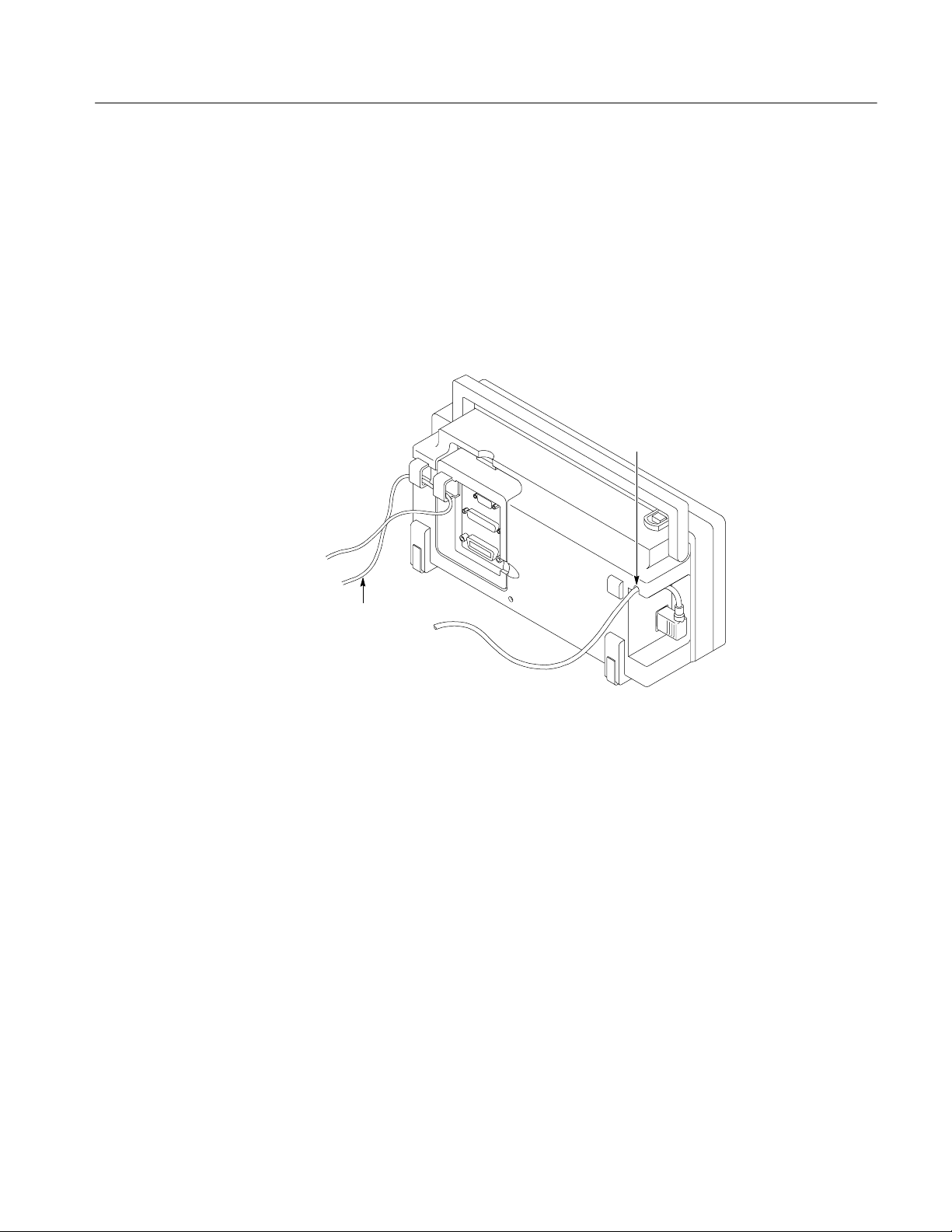
Operating Information
TDS 200 Series Digital Oscilloscope Service Manual
2--3
Installation
Use only power cords designed for your oscilloscope. Use a power source that
delivers 85 to 275 VAC
RMS
,47to63Hz.Refertopage10——9foralistof
available power cords.
Use the power cord notch to help route the cord to the rear of the instrument and
avoid inadvertently disconnecting the power source.
Securing cable
Power cord
notch
Figure 2-1: Routing the power cord and security cable
Use the built-in cable channels to secure both your instrument and extension
module to your location.
Power Cord
Security Loop
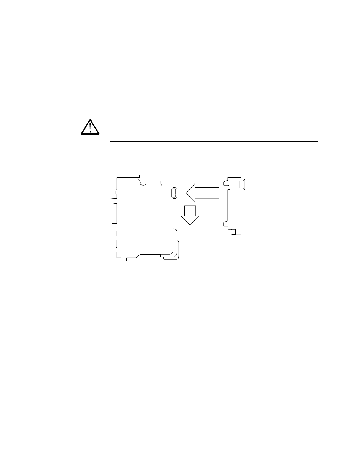
Operating Information
2--4
TDS 200 Series Digital Oscilloscope Service Manual
Extension Modules
You can increase the feature set of your oscilloscope by inserting an extension
module. Refer to page 10—-9 for information about the available modules.
Figure 2-2 shows the proper way to install a module without bending the
connecting pins.
CAUTION. Electrostatic discharge (ESD) can damage components in the
extension module and the oscilloscope. Do not operate your instrument with the
extension module connector exposed.
1
2
Figure 2-2: Installing an extension module
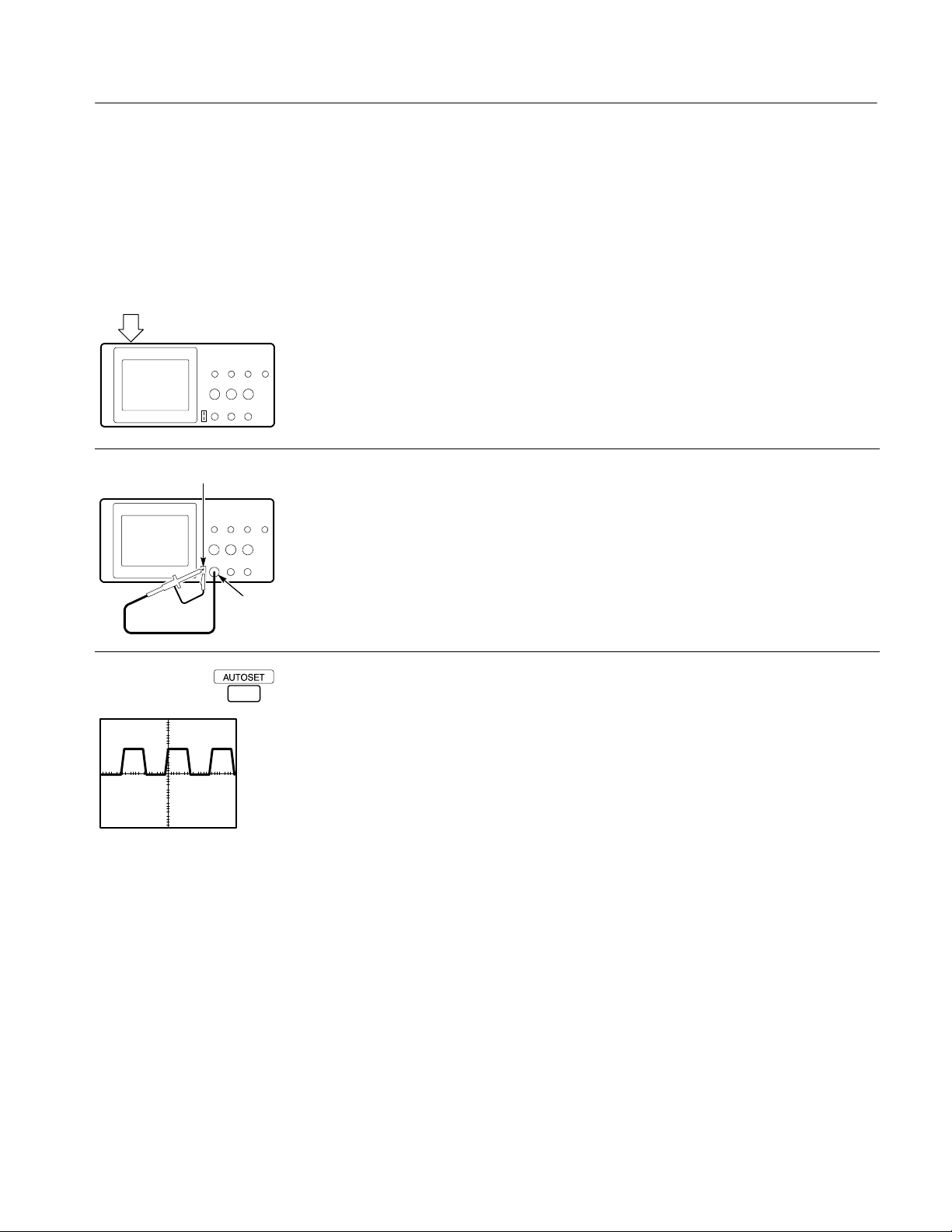
Operating Information
TDS 200 Series Digital Oscilloscope Service Manual
2--5
Functional Check
Perform this quick functional check to verify that your instrument is operating
correctly.
PASSED
ON/OFF
button
1. Turn on the instrument.
Wait until the display shows that all self tests passed. Push the SAVE/RECALL
button, select Setups in the top menu box and push the Recall Factory menu
box. The default Probe menu attenuation setting is 10X.
CH 1
PROBE COMP
2. Set the switch to 10X on the P2100 probe and connect the oscilloscope probe to
channel 1. To do this, align the slot in the probe connector with the key on the
CH 1 BNC, push to connect, and twist to the right to lock the probe in place.
Attach the probe tip and reference lead to the PROBE COMP connectors.
3. Push the AUTOSET button. Within a few seconds, you should see a square
wave in the display (approximately 5 V at 1 kHz peak-to-peak).
Push the CH 1 MENU button twice to turn off channel 1, push the CH 2 MENU
button to turn on channel 2, repeat steps 2 and 3. For TDS 224, repeat for CH 3
and CH 4.
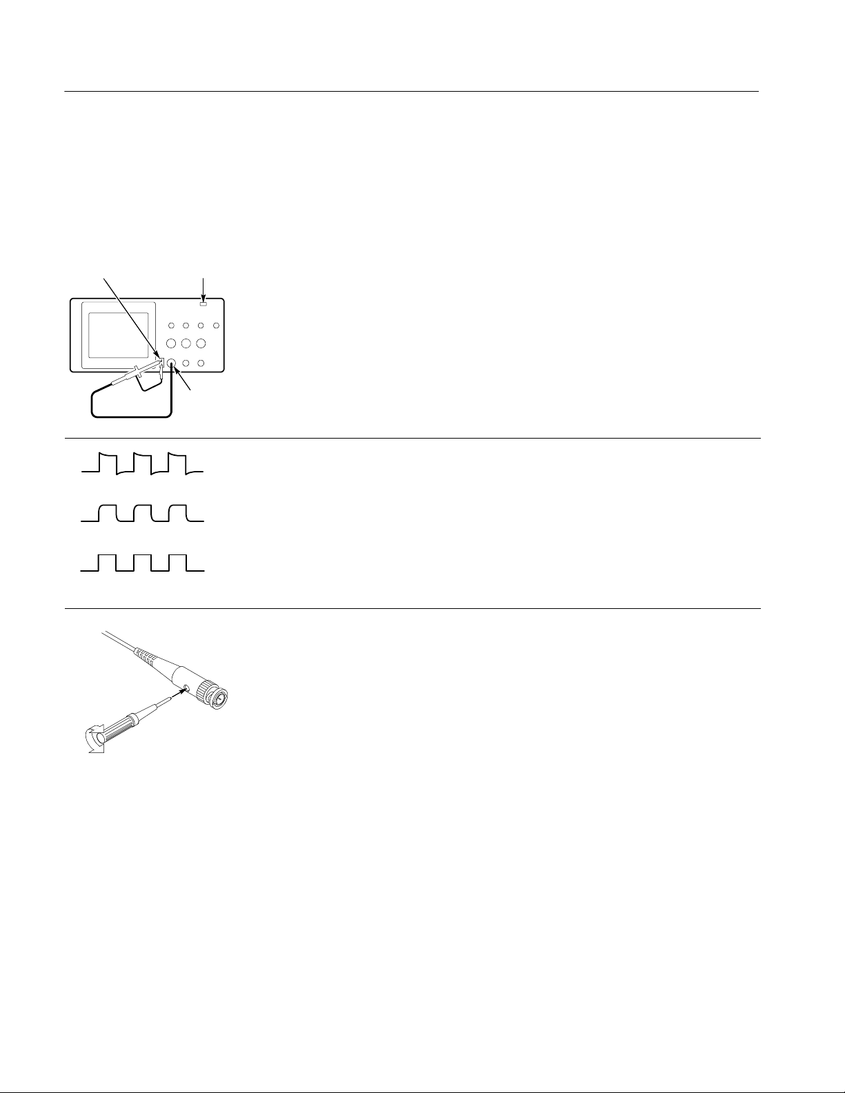
Operating Information
2--6
TDS 200 Series Digital Oscilloscope Service Manual
Probe Compensation
Perform this adjustment to match your probe to the input channel. This should be
done whenever you attach a probe for the first time to any input channel.
CH 1
PROBE
COMP
UTOSE
T button
1. Set the Probe menu attenuation to 10X. Set the switch to 10X on the P2100
probe and connect the oscilloscope probe to channel 1. Attach the probe tip and
reference lead to the PROBE COMP connectors and then press AUTOSET.
If using the probe hook-tip, ensure a proper connection by firmly twisting the
tip onto the probe.
Overcompensated
Compensated correctly
Undercompensated
2. Check the shape of the displayed waveform.
3. If necessary, adjust your probe.
Repeat as necessary.
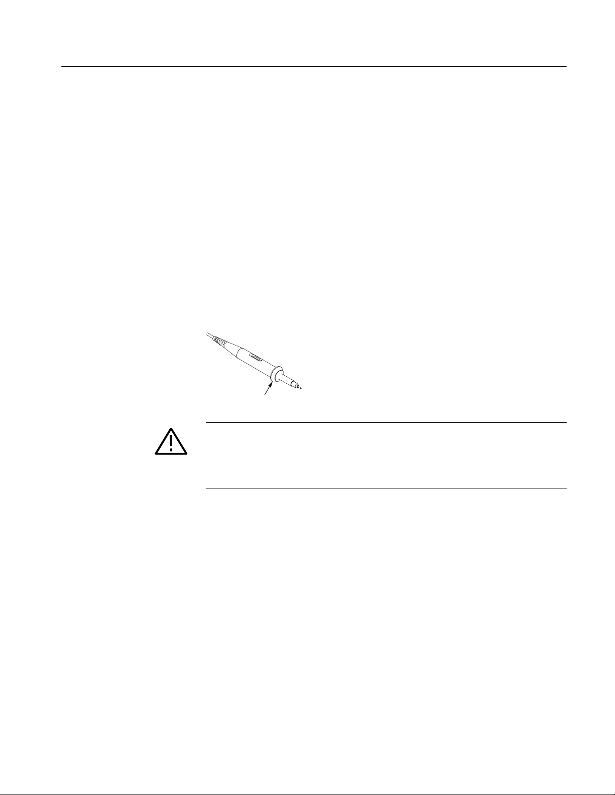
Operating Information
TDS 200 Series Digital Oscilloscope Service Manual
2--7
Self Calibration
The self calibration routine lets you quickly optimize the oscilloscope signal path
for maximum measurement accuracy. You can run the routine at anytime but you
should always run the routine if the ambient temperature changes by 5_ Cor
more.
To compensate the signal path, disconnect any probes or cables from the channel
input connectors. Then, press the UTILITY button and select Do Self Cal to
confirm that you are ready to proceed.
Probe Safety
A guard around the probe body provides a finger barrier for protection from
electric shock.
Finger guard
WARNING. To avoid electric shock when using the probe, keep fingers behind the
guard on the probe body.
To avoid electric shock while using the probe, do not touch metallic portions of
the probe head while it is connected to a voltage source.
Connect the probe to the instrument and connect the ground terminal to ground
before you take any measurements.
Probe Attenuation Setting
Probes are available with various attenuation factors which affect the vertical
scale readout of the oscilloscope.
To change (or check) the probe attenuation setting, press the VERTICAL MENU
button (of the channel you’re using) and then press the menu selection next to
Probe until the correct setting is displayed.
This setting remains in effect until changed again.
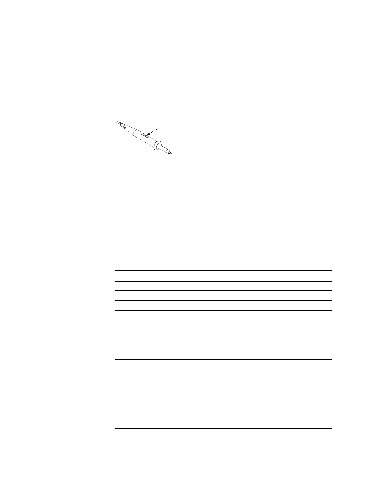
Operating Information
2--8
TDS 200 Series Digital Oscilloscope Service Manual
NOTE. The default Probe menu attenuation setting is 10X when the oscilloscope
is shipped.
Be sure that the Attenuation switch on the P2100 probe is set to match the Probe
menu selection in the oscilloscope. The probe switch settings are 1X and 10X.
Attenuation switch
NOTE. When the Attenuation switch is set to 1X, the P2100 probe limits the
bandwidth of the oscilloscope to 7 MHz. To use the full bandwidth of the
oscilloscope, be sure to set the switch to 10X.
Factory Setup
The table below lists the state of the instrument after you select Recall Factory
from the SAVE/RECALL menu.
Tab le 2 — —1: Factory setup settings
Control Setting
Acquire mode Sample
Acquire # of averages 16
Channel selection Channel 1 on
Cursor H Bar position —-3.2 divisions from the center
Cursor V Bar position ——2 divisions from the center
Cursor function Off
Cursor time units Seconds
Delayed time base time/div
50 s/div
Delay time, delayed runs after main
50 s
Display format YT
Display graticule type Full
Display contrast 50%
Display style Vectors
Display accumulate time 500 ms
Edge trigger coupling DC

Operating Information
TDS 200 Series Digital Oscilloscope Service Manual
2--9
Tab le 2 — —1: Factory setup settings (cont.)
Control Setting
Edge trigger level 0.0 V
Edge trigger slope Rising
Edge trigger source Channel 1
Horizontal —— main trigger position 50%
Horizontal —— time base Main only
Main time base time/div
500 s/div
Math waveform function CH1 + CH2
Saved setups No change
Saved waveforms No change
Trigger holdoff Minimum (500 ns)
Trigger mode Auto
Trigger type Edge
Vertical bandwidth (all channels) Full
Vertical coupling (all channels) DC
Vertical position (all channels) 0div
Vertical volts/div. (all channels) 100 mV/div

Operating Information
2--10
TDS 200 Series Digital Oscilloscope Service Manual

TDS 200 Series Digital Oscilloscope Service Manual
3--1
Theory of Operation
This chapter describes the electrical operation of the TDS 200-Series Digital
Real-Time Oscilloscope to the module level. It describes the basic operation of
each functional circuit block shown in figures 3-1 and 3-2.
Main Board
The Main board contains a two or four channel acquisition system, trigger
system, acquisition/display controller, and system processor. Interfaces are
provided for two signal inputs, external trigger input, probe compensation, front
panel, LCD display, extension module, and power supply. Acquisition and
display functions are implemented in two application specific integrated circuits
(ASICs).
Signals from the CH 1, CH 2, and EXT TRIG, or CH 1, CH 2, CH 3, and CH 4
input connectors pass through attenuators to the acquisition ASIC. The acquisi-
tion ASIC contains amplifiers and samplers for each input channel, A/D
converter, and trigger logic. The digitized waveform samples are transferred to
the display ASIC. Low voltage regulators supply isolated power to the acquisi-
tion ASIC.
The display system consists of the display ASIC, DRAM memory, and system
oscillator. Digitized acquisition samples are processed by the display ASIC and
stored into DRAM. The Display ASIC formats the waveform data and generates
drive signals for the LCD display. Front panel scanning is also performed by the
display ASIC.
The processor system consists of the microprocessor and memory. The processor
system interprets the front panel controls, programs acquisition and display
parameters, computes waveform measurements, and manages the extension
module interface. Saved setups, waveforms, and calibration constants are stored
in nonvolatile memory. The processor system shares DRAM with the display
system.
BNC connectors are mounted on the main board for the CH 1, CH 2, and trigger
or CH 1, CH 2, CH 3, and CH 4 inputs. The signal inputs are compatible with the
P2100 probes supplied.
The PROBE COMP and ground terminals are provided for probe adjustment.
Acquisition System
Display System
Processor System
Input Signal Interface
Probe Compensation

Theory of Operation
3--2
TDS 200 Series Digital Oscilloscope Service Manual
Power Supply
The power supply module generates low voltage DC, a line trigger signal for the
main board, and high voltage AC to power the LCD backlight. The power supply
operates over a wide power line voltage and frequency range.
Display Module
The display module consists of a liquid crystal display (LCD), a display driver,
and a florescent backlight.
Front Panel
The front panel board holds the encoders and push button contacts that the
operator uses to control the instrument. An elastomer mat holds the conductive
pads for the push buttons. Circuits on the front panel convert the matrix into
serial data which is read by the display ASIC on the main Board.
Extension Modules
Each extension module also contains a GPIB, RS—-232, and Centronics parallel
printer interface. A ROM on the extension module contains processor instruc-
tions to support the communications interfaces. Extension modules interface with
the processor system through the extension module port connector.
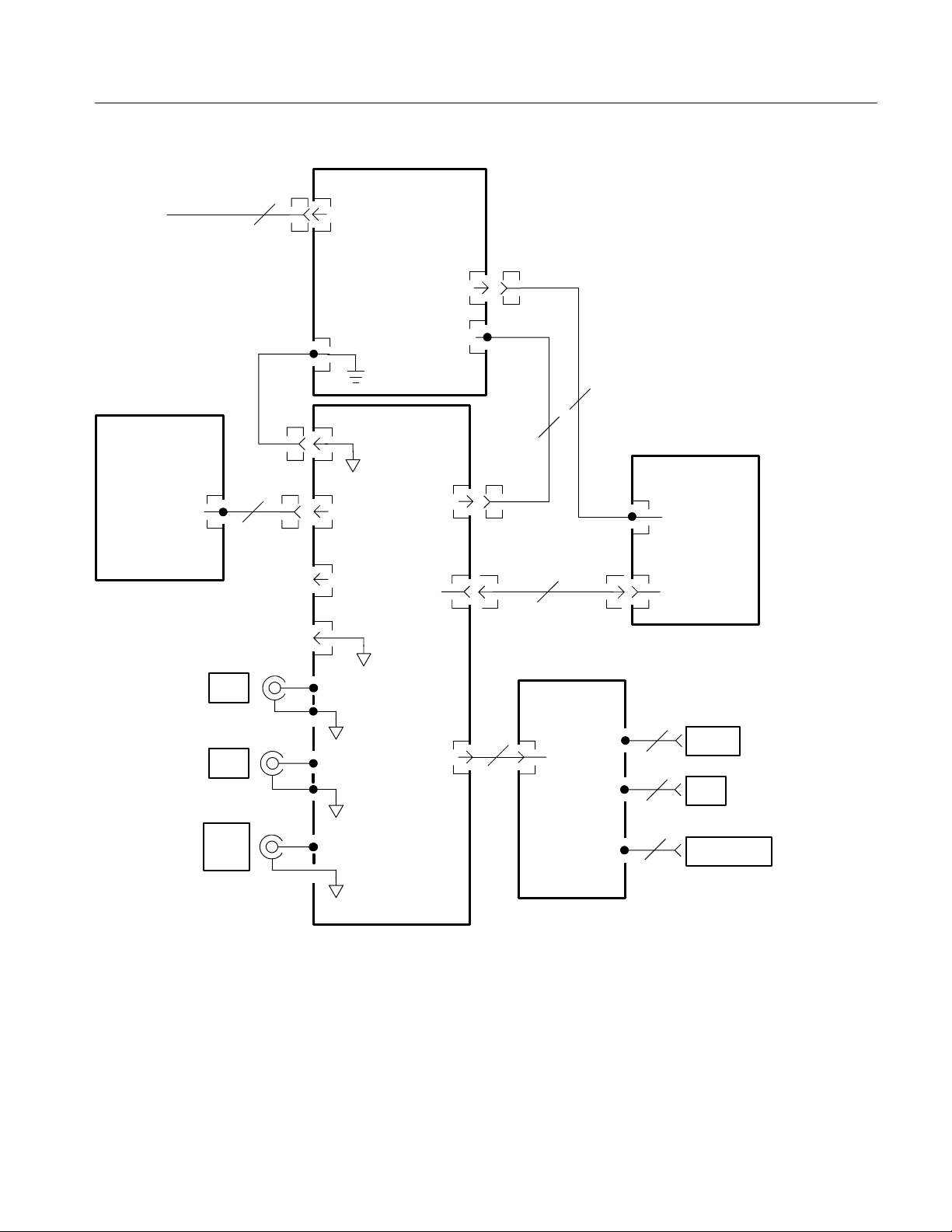
Theory of Operation
TDS 200 Series Digital Oscilloscope Service Manual
3--3
Extension
Module
CH1
P53
2
P3
J603
LCD
5
EXT
TRIG
J51
J52
J53
DC In
Display Control
5
0
J601
J2
J4
J3
RS232
GPIB
CENTRONICS
Front Panel
A1 Main
Display
CH2
P131
Backlight
Probe Comp
Signal
7
GND
GND
Backlight Power
3
AC Line In
Power Supply
AC Line
DC Out
&Line
Trigger
J602
J604
J1
Probe Comp
GND
J605
J202
J131
12
J902
J90
1
9
24
25
Figure 3-1: Module-level block diagram (two channel)
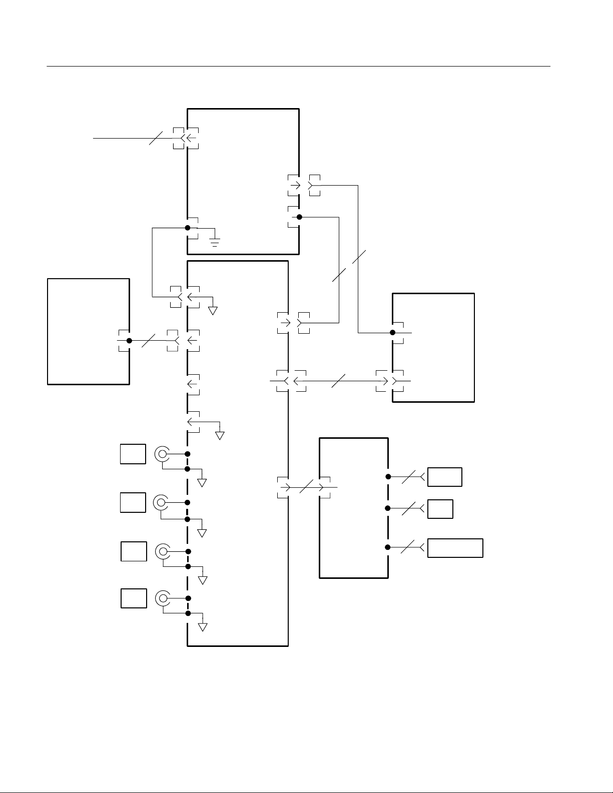
Theory of Operation
3--4
TDS 200 Series Digital Oscilloscope Service Manual
Extension
Module
CH1
J1
2
P3
J103
LCD
5
J200
J250
DC In
Display Control
5
0
J690
J2
J4
J3
RS232
GPIB
CENTRONICS
Front Panel
A1 Main
Display
CH2
P131
Backlight
Probe Comp
Signal
7
GND
GND
Backlight Power
3
AC Line In
Power Supply
AC Line
DC Out
&Line
Trigger
J101
J104
J1
Probe Comp
GND
J104
J102
J131
12
J902
J90
1
9
24
25
CH3
J300
CH4
J350
Figure 3-2: Module-level block diagram (four channel)

TDS 200 Series Digital Oscilloscope Service Manual
4--1
Performance Verification
This chapter contains performance verification procedures for the specifications
marked with the n symbol. The following equipment, or a suitable equivalent, is
required to complete these procedures.
Description
Minimum
requirements
Examples
DC Voltage Source 17.5mVto7V,±0.5%
accuracy
Wavetek 9100 Universal
Calibration System with
Oscillosco
e Calibration
Leveled Sine Wave Generator 50 kHz and 100 MHz, ±3%
amplitude accuracy
Module (Option 250)
Fluke 5500A Multi-product
Time Mark Generator 10 ms period, ±25 ppm
accuracy
Calibrator with Oscilloscope
Calibration Option (Option
5500A-SC)
50 Ω BNC Cable
BNCmaletoBNCmale,
≈ 36 in (1 m) long
Tektronix part number
012-0482-00
50 Ω BNC Cable
BNCmaletoBNCmale,
≈ 10 in (25 cm) long
Tektronix part number
012-0208-00
50 Ω Feedthrough Termination
BNC male and female
connectors
Tektronix part number
011-0049-01
Dual Banana to BNC Adapter Banana plugs to BNC female Tektronix part number
103-0090-00
BNC T Adapter BNC male to dual BNC female
connectors
Tektronix part number
103-0030-00
 Loading…