- Manuals
- Brands
- FLIR Manuals
- Thermal cameras
- E50
Manuals and User Guides for FLIR E50. We have 2 FLIR E50 manuals available for free PDF download: User Manual, Step-By-Step Manual
FLIR E50 User Manual (183 pages)
Brand: FLIR
|
Category: Thermal cameras
|
Size: 8.02 MB
Table of Contents
-
Table of Contents
5
-
1 Disclaimers
11
-
Legal Disclaimer
11
-
Usage Statistics
11
-
Changes to Registry
11
-
Government Regulations
11
-
Copyright
11
-
Quality Assurance
11
-
Patents
11
-
EULA Terms
11
-
-
2 Safety Information
13
-
3 Notice to User
17
-
User-To-User Forums
17
-
Calibration
17
-
Accuracy
17
-
Disposal of Electronic Waste
17
-
Training
17
-
Documentation Updates
17
-
Important Note about this Manual
17
-
Note about Authoritative Versions
17
-
-
4 Customer Help
18
-
General
18
-
Submitting a Question
18
-
Downloads
19
-
-
5 Quick Start Guide
20
-
Procedure
20
-
-
6 List of Accessories and Services
21
-
7 Camera Parts
23
-
View from the Right
23
-
Explanation
23
-
Figure
23
-
-
View from the Left
24
-
Explanation
24
-
Figure
24
-
-
LCD and Keypad
25
-
Explanation
25
-
Figure
25
-
-
View from the Bottom
26
-
Explanation
26
-
Figure
26
-
-
Battery Condition LED Indicator
27
-
Explanation
27
-
Figure
27
-
-
Laser Pointer
28
-
Figure
28
-
Laser Rules and Regulations
28
-
Laser Warning Label
28
-
-
-
8 Screen Elements
29
-
Figure
29
-
Explanation
29
-
-
-
9 Navigating the Menu System
30
-
Figure
30
-
Explanation
30
-
-
-
10 Connecting External Devices and Storage Media
31
-
Figure
31
-
Explanation
31
-
Figure
32
-
Explanation
32
-
-
-
11 Pairing Bluetooth Devices
33
-
General
33
-
Procedure
33
-
-
12 Configuring Wi-Fi
34
-
General
34
-
Setting up a Peer-To-Peer Connection (most Common Use)
34
-
Connecting the Camera to a Wireless Local Area Network (Less Common Use)
34
-
-
13 Handling the Camera
35
-
Charging the Battery
35
-
Using the Power Supply to Charge the Battery
35
-
Using the Stand-Alone Battery Charger to Charge the Battery
35
-
-
Turning on and Turning off the Camera
35
-
Adjusting the Infrared Camera Focus
36
-
Figure
36
-
Procedure
36
-
-
Operating the Laser Pointer
37
-
Figure
37
-
Procedure
37
-
-
Removing the Battery
37
-
Mounting an Accessory Lens
38
-
Calibrating the Touchscreen
39
-
Figure
39
-
Procedure
39
-
-
Using the Camera Lamp
39
-
General
39
-
Procedure
40
-
-
-
14 Working with Images
41
-
Saving an Image
41
-
General
41
-
Image Capacity
41
-
Naming Convention
41
-
Procedure
41
-
-
Previewing an Image
41
-
Opening a Saved Image
42
-
General
42
-
Procedure
42
-
-
Editing a Saved Image
42
-
Adjusting an Infrared Image
42
-
Example 1
43
-
Example 2
43
-
Manual Adjustment in Level / Span Mode
43
-
Manual Adjustment in Level / Max / Min Mode
44
-
-
Performing a Non-Uniformity Correction (NUC)
44
-
What Is a Non-Uniformity Correction
44
-
When to Perform a Non-Uniformity Correction
44
-
Procedure
44
-
-
Changing the Temperature Range
44
-
General
44
-
-
Changing the Color Palette
45
-
General
45
-
Procedure
45
-
-
Zooming in on an Image
45
-
Deleting an Image
45
-
Deleting All Images
46
-
Procedure
46
-
-
-
15 Working with Image Modes
47
-
General
47
-
Types of Image Modes
47
-
Procedure
48
-
-
16 Working with Measurement Tools
49
-
Laying out Measurement Tools in Live Mode
49
-
General
49
-
Procedure
49
-
-
Laying out Measurement Tools in Edit Mode
49
-
Moving and Resizing Measurement Tools
50
-
General
50
-
Procedure
50
-
-
Displaying Maximum, Minimum, and Average Values
50
-
Setting Local Measurement Parameters for a Measurement Tool
51
-
General
51
-
Procedure
51
-
-
-
17 Working with Alarms
52
-
Working with Color Alarms
52
-
General
52
-
Procedure
52
-
-
Working with Insulation Alarms
52
-
Working with Condensation Alarms
53
-
General
53
-
Procedure
53
-
-
-
18 Fetching Data from External FLIR Meters
54
-
General
54
-
Supported Meters
54
-
Technical Support for External Meters
54
-
Procedure
54
-
Typical Moisture Measurement and Documentation Procedure
54
-
-
19 Annotating Images
55
-
General
55
-
Adding a Note
55
-
Procedure
55
-
-
Adding a Table
55
-
Procedure
56
-
-
Adding a Voice Annotation
56
-
General
56
-
-
-
20 Recording Video Clips
57
-
General
57
-
Procedure: Recording a Video Clip
57
-
Procedure: Playing a Video Clip
57
-
-
21 Screening Alarm
58
-
General
58
-
Procedure
58
-
-
22 Changing Settings
59
-
General
59
-
Procedure
59
-
Description of the Various Settings
59
-
Measurement Parameters
59
-
Save Options
60
-
Add-On Lens
60
-
Device Settings
60
-
-
-
23 Technical Data
62
-
Online Field-Of-View Calculator
62
-
Note about Technical Data
62
-
Note about Authoritative Versions
62
-
Flir E33
63
-
Flir E40
68
-
FLIR E40 (Incl. Wi-Fi)
73
-
FLIR E40 with SC Kit (Incl. Wi-Fi and 45° Lens)
78
-
FLIR E40 with SC Kit (Incl. Wi-Fi)
83
-
FLIR E40Bx (Incl. Wi-Fi)
88
-
Flir E50
93
-
FLIR E50 (Incl. Wi-Fi)
98
-
FLIR E50Bx (Incl. Wi-Fi)
103
-
Flir E60
108
-
FLIR E60 (Incl. Wi-Fi)
113
-
FLIR E60 with Educational Kit (DE)
118
-
FLIR E60 with Educational Kit (EN)
119
-
FLIR E60 with Educational Kit (ES)
120
-
FLIR E60 with Educational Kit (FR)
121
-
FLIR E60 with Educational Kit (IT)
122
-
FLIR E60 with Educational Kit (JA)
123
-
FLIR E60 with Educational Kit (KO)
124
-
FLIR E60Bx (Incl. Wi-Fi)
125
-
FLIR E63 (Incl. Wi-Fi)
130
-
-
24 Mechanical Drawings
135
-
25 CE Declaration of Conformity
140
-
26 Cleaning the Camera
142
-
Camera Housing, Cables, and Other Items
142
-
Liquids
142
-
Equipment
142
-
Procedure
142
-
-
Infrared Lens
142
-
-
27 Application Examples
143
-
Moisture & Water Damage
143
-
General
143
-
Figure
143
-
-
Faulty Contact in Socket
143
-
Oxidized Socket
144
-
General
144
-
Figure
144
-
-
Insulation Deficiencies
145
-
General
145
-
Figure
145
-
-
Draft
145
-
-
28 About FLIR Systems
147
-
More than Just an Infrared Camera
148
-
Sharing Our Knowledge
148
-
Supporting Our Customers
148
-
-
29 Glossary
150
-
30 Thermographic Measurement Techniques
153
-
Introduction
153
-
Emissivity
153
-
Finding the Emissivity of a Sample
153
-
-
Reflected Apparent Temperature
156
-
Distance
157
-
Relative Humidity
157
-
Other Parameters
157
-
-
31 History of Infrared Technology
158
-
32 Theory of Thermography
161
-
Introduction
161
-
The Electromagnetic Spectrum
161
-
Blackbody Radiation
161
-
Planck’s Law
162
-
Wien’s Displacement Law
163
-
Stefan-Boltzmann’s Law
164
-
Non-Blackbody Emitters
165
-
-
Infrared Semi-Transparent Materials
167
-
-
33 The Measurement Formula
168
-
34 Emissivity Tables
172
-
References
172
-
Tables
172
-
Advertisement
FLIR E50 Step-By-Step Manual (2 pages)
How to upgrade your FLIR E40 to E60 (Resolution hack)
Brand: FLIR
|
Category: Thermal cameras
|
Size: 0.23 MB
Advertisement
Related Products
-
FLIR E54
-
FLIR E54-EST
-
FLIR E54-24
-
FLIR FLIR E95
-
FLIR E40
-
FLIR EST Series
-
FLIR E76
-
FLIR E70354
-
FLIR E70353
-
FLIR E70431
FLIR Categories
Thermal cameras
![]()
Security Camera
Measuring Instruments
![]()
Digital Camera
IP Camera
More FLIR Manuals
- Manuals
- Brands
- FLIR Manuals
- Thermal cameras
- E series
- User manual
-
Contents
-
Table of Contents
-
Bookmarks
Quick Links
User’s manual
FLIR Exx series
Related Manuals for FLIR E Series
Summary of Contents for FLIR E Series
-
Page 1
User’s manual FLIR Exx series… -
Page 2
Important note Before operating the device, you must read, understand, and follow all instructions, warnings, cautions, and legal disclaimers. Důležitá poznámka Před použitím zařízení si přečtěte veškeré pokyny, upozornění, varování a vyvázání se ze záruky, ujistěte se, že jim rozumíte, a řiďte se jimi. -
Page 3: Table Of Contents
Table of contents Disclaimers ………………1 Legal disclaimer …………… 1 U.S. Government Regulations…………1 Patents ………………. 1 Quality assurance …………..1 Third-party licenses…………..1 Usage statistics ……………. 1 Copyright …………….1 Safety information …………….2 Notice to user ……………….6 Online documentation…………..6 Register your camera…………..
-
Page 4
Table of contents Operating the laser distance meter ……….22 7.5.1 General…………..22 7.5.2 Procedure …………..22 Measuring areas…………..23 7.6.1 General…………..23 7.6.2 Procedure …………..23 Connecting external devices and storage media ……24 Moving files to a computer …………24 Programmable button ………….. -
Page 5
Table of contents 10.3.2 Manual adjustment by touching the screen ……51 10.3.3 Manual adjustment by using the navigation pad ….52 10.3.4 Manual adjustment in Level, Span mode ……52 10.3.5 Manual adjustment in Level, Max, Min mode …… 53 10.4 Changing the camera temperature range …….. -
Page 6
Configuring Wi-Fi …………….89 20.1 Setting up a wireless access point ……….89 20.2 Connecting the camera to a WLAN ……….89 Fetching data from external FLIR meters ……….90 21.1 General …………….90 21.2 Technical support for external meters ………. 90 21.3… -
Page 7
Table of contents About FLIR Systems …………..105 27.1 More than just an infrared camera ……….106 27.2 Sharing our knowledge …………106 27.3 Supporting our customers…………107 #T810587; r. AA/74078/74713; en-US… -
Page 8: Disclaimers
1.7 Copyright © 2021 FLIR Systems, Inc. All rights reserved worldwide. No parts of the software in- cluding source code may be reproduced, transmitted, transcribed or translated into any language or computer language in any form or by any means, electronic, magnetic, opti- cal, manual or otherwise, without the prior written permission of FLIR Systems.
-
Page 9: Safety Information
WARNING Applicability: Digital devices subject to 15.21. NOTICE: Changes or modifications made to this equipment not expressly approved by FLIR Systems may void the FCC authorization to operate this equipment. WARNING Applicability: Digital devices subject to 2.1091/2.1093/KDB 447498/RSS-102.
-
Page 10
High temperatures can cause damage to the camera. CAUTION Do not attach the batteries directly to a car’s cigarette lighter socket, unless FLIR Systems supplies a specific adapter to connect the batteries to a cigarette lighter socket. Damage to the batteries can occur. -
Page 11
Safety information CAUTION Do not put the battery on or near fires, stoves, or other high-temperature locations. Damage to the bat- tery and injury to persons can occur. CAUTION Do not solder directly onto the battery. Damage to the battery can occur. CAUTION Do not use the battery if, when you use, charge, or put the battery in storage, there is an unusual smell from the battery, the battery feels hot, changes color, changes shape, or is in an unusual condition. -
Page 12
Safety information Note The encapsulation rating is only applicable when all the openings on the camera are sealed with their correct covers, hatches, or caps. This includes the compartments for data storage, batteries, and connectors. #T810587; r. AA/74078/74713; en-US… -
Page 13: Notice To User
To register the camera, go to http://support.flir.com/camreg. To access the registration form, you must log in to your FLIR account or sign up for a new account. You will also need the serial number of your camera. The serial number is displayed by the registration wizard in the camera.
-
Page 14: Note About Authoritative Versions
Notice to user 3.7 Note about authoritative versions The authoritative version of this publication is English. In the event of divergences due to translation errors, the English text has precedence. Any late changes are first imple- mented in English. 3.8 Disposal of electronic waste Electrical and electronic equipment (EEE) contains materials, components and substan- ces that may be hazardous and present a risk to human health and the environment when waste electrical and electronic equipment (WEEE) is not handled correctly.
-
Page 15: Customer Help
• The communication protocol, or method, between the camera and your device (e.g., SD card reader, HDMI, Ethernet, USB, or FireWire). • Device type (PC/Mac/iPhone/iPad/Android device, etc.). • Version of any programs from FLIR Systems. • Full name, publication number, and revision number of the manual. 4.3 Downloads…
-
Page 16: Quick Start Guide
8. Pull the trigger to save an image. 9. When you have completed the inspection, connect the camera to a computer using the USB cable. 10. Import the images into a FLIR Thermography software and create an inspection report. 5.1 To keep in mind •…
-
Page 17: Camera Overview
Camera overview 6.1 View from the front 1. Laser distance meter. 2. Infrared lens. 3. Focus ring. 4. Autofocus button. 5. Trigger. 6. Lamp for the digital camera (left and right sides). 7. Digital camera. 8. Attachment point for the hand strap bracket (left and right sides). 9.
-
Page 18: View From The Rear
Camera overview 6.2 View from the rear 1. Cover for the USB connector and memory card slot. 2. Microphone. 3. Speaker. 4. Touch-screen LCD. 5. Image archive button. 6. Programmable button. 7. Button to operate the laser. 8. Back button. 9.
-
Page 19: Laser Transmitter And Receiver
Camera overview 6.3.1 Laser transmitter and receiver 1. Laser transmitter. 2. Laser receiver. 6.3.2 Difference in position This figure shows the difference in position between the laser transmitter and the optical center of the infrared lens. 2. This item is dependent on the camera model. #T810587;…
-
Page 20: Laser Warning Label
Camera overview 6.3.3 Laser warning label A laser warning label with the following information is attached to the camera: 6.3.4 Laser rules and regulations Wavelength: 650 nm. Maximum output power: 1 mW. This product complies with 21 CFR 1040.10 and 1040.11 except for deviations pursuant to Laser Notice No.
-
Page 21: Status Icons And Indicators
Camera overview 1. Temperature scale button. 2. Measurement parameters button. 3. Image mode button. 4. Measurement button. 5. Color button. 6. Settings button. 7. Main menu. 8. Submenu. 6.4.3 Status icons and indicators Battery status indicator. • When the battery status is 20–100%, the indicator is white. •…
-
Page 22: Image Overlay Information
Camera overview 1. Battery status indicator. 2. Memory card storage status indicator. 3. • Wi-Fi button: Touch to enable/disable Wi-Fi. See also section 20 Configuring Wi- • Bluetooth button: Touch to enable/disable Bluetooth. See also section 19 Pairing Bluetooth devices. •…
-
Page 23: Navigating The Menu System
Camera overview 6.5 Navigating the menu system You can navigate the menu system in two ways: • Using your finger or a stylus pen specially designed for capacitive touch usage. • Using the navigation pad and the back button 6.5.1 Navigating using the navigation pad You navigate the menu system by using the navigation pad and the back button: •…
-
Page 24: Handling The Camera
Handling the camera 7.1 Charging the battery 7.1.1 General • Before starting the camera for the first time, charge the battery for 2 hours using the stand-alone battery charger. • Select a mains socket that is near the equipment and easily accessible. 7.1.2 Using the stand-alone battery charger to charge the battery 1.
-
Page 25: Charging The Battery Using A Usb Cable Connected To A Computer
Handling the camera 4. Connect the USB connector of the USB battery charger to the USB-C connector in the connector bay of the camera. 5. To check the status of the battery charging, do one of the following: • If the camera is turned on: Place your finger at the top of the screen and swipe down.
-
Page 26: Removing The Battery
Handling the camera 2. Connect a USB cable to the USB-C connector in the connector bay. Connect the oth- er end of the USB cable to the computer. Note • To charge the camera, the computer must be turned on. •…
-
Page 27: Adjusting The Thermal Camera Focus
Handling the camera 7.4 Adjusting the thermal camera focus It is very important to adjust the focus correctly. Incorrect focus adjustment affects how the image modes work. It also affects the temperature measurement. You can adjust the camera focus by rotating the focus ring or by pushing the autofocus button.
-
Page 28: Continuous Autofocus
Handling the camera Note • You can also assign the autofocus function to the programmable button. For more in- formation, see section 7.9 Programmable button. • Autofocus is not supported by all camera models. 7.4.2.1 Autofocus method When autofocusing, the camera can use one of the following focus methods: •…
-
Page 29: Operating The Laser Distance Meter
Handling the camera Note • Before you can enable continuous autofocus, you need to enable the laser and select laser as focus method. See section 7.4.2.1 Autofocus method. • When continuous autofocus is enabled, it is not possible to manually adjust the focus by rotating the focus ring.
-
Page 30: Measuring Areas
Handling the camera 7.6 Measuring areas 7.6.1 General Note The availability of this feature is dependent on the camera model. The distance measured by the laser distance meter can be used as the basis for area calculations. A typical application is to estimate the size of a damp stain on a wall. To measure the area of a surface, you need to lay out a box or circle measurement tool on the screen.
-
Page 31: Connecting External Devices And Storage Media
Handling the camera 5. Hold the camera perpendicular to the target. Push and hold the laser button 6. The calculated area is displayed in the result table. 7.7 Connecting external devices and storage media You can connect the following external devices and media to the camera: •…
-
Page 32
• Move the files to the computer using a drag-and-drop operation. Note Moving a file using a drag-and-drop operation does not delete the file in the camera. • Import the images into a FLIR Thermography software. #T810587; r. AA/74078/74713; en-US… -
Page 33: Programmable Button
Handling the camera 7.9 Programmable button You can assign different functions to the programmable button. You can, for example, use the programmable button to easily switch between two settings you use often. You can also choose to define two different setups for saving and previewing: the ordinary setup for the trigger (which is defined by the Save options and storage settings, see sec- tion 22.4 Save options &…
-
Page 34: Using The Camera Lamp As A Flash
Handling the camera • Switch Auto <> Manual temperature scale: Switch between automatic or manual im- age adjustment mode. For more information, see section 10.3 Adjusting the infrared image. • Autofocus : One-shot autofocus of the infrared camera. • Continuous autofocus : Switch between the enabled/disabled continuous autofocus functions.
-
Page 35: Hand Strap
Handling the camera 2. Select (Settings) and push the navigation pad. This displays the Settings menu. 3. Use the navigation pad to select Device settings > Lamp & laser. 4. To use the camera lamp as a flash, do one of the following: •…
-
Page 36: Mounting The Hand Strap
Handling the camera 7.11.1 Mounting the hand strap 1. Fit the upper part of the hand strap into the bracket. 2. Fit the bracket in place on the camera and tighten the screw with the supplied Torx key. #T810587; r. AA/74078/74713; en-US…
-
Page 37
Handling the camera 3. Thread the loose strap through the attachment point at the base of the camera. Se- cure the strap with the hook-and-loop fastener. #T810587; r. AA/74078/74713; en-US… -
Page 38: Lanyard Strap
Handling the camera 7.12 Lanyard strap To mount the lanyard strap, do the following: 1. Remove the camera battery. #T810587; r. AA/74078/74713; en-US…
-
Page 39: Wrist Strap
Handling the camera 2. Starting with the FLIR logo part, thread the lanyard strap through the attachment point at the base of the camera. 3. Pull the entire lanyard strap through the attachment point until it stops. 7.13 Wrist strap The wrist strap can also be used to attach a carabiner to the camera.
-
Page 40: Front Protection
Handling the camera 2. Fold the wrist strap. Make sure that the part with the FLIR logo faces away from the bend. 3. Thread the bent wrist strap through the attachment point at the base of the camera. 4. Pull the entire wrist strap through the attachment point until it stops.
-
Page 41: Changing Camera Lenses
Handling the camera 7.15 Changing camera lenses Applicability: Camera models with an exchangeable lens. Note If the new lens has not been used with the camera before, the lens–camera com- bination must be calibrated after the lens has been mounted. See section 7.16 Calibrat- ing the lens–camera combination for information on how to do this.
-
Page 42
Handling the camera 2. Carefully pull out the lens. 3. The infrared detector is now fully exposed. Do not touch this surface. If you see dust on the detector, follow the instructions in 23.3 Infrared detector. #T810587; r. AA/74078/74713; en-US… -
Page 43
Handling the camera 4. Make sure that the inner ring of the camera lens is fully in its open position. • Correct: The tooth (1) is in its end position at the black stop pin (2). • Wrong: You must rotate the inner ring until the tooth (1) reaches the black stop pin (2). -
Page 44: Calibrating The Lens-Camera Combination
Before a new lens can be used with the camera, the lens–camera combination must be calibrated. This is a process that previously had to be performed by a FLIR service department, but for the FLIR Exx series the calibration can be performed by the user. This feature is called AutoCal.
-
Page 45: Autocal Procedure
Handling the camera 7.16.2 AutoCal procedure 1. Dip the calibration target in water for 1 second and let the excess drip off. 2. Tape or hang the calibration target on a wall. 3. Mount the new lens on the camera according to the procedure in section 7.15 Changing camera lenses.
-
Page 46: Calibrating The Compass
Handling the camera 4. From a distance of 2 m (6.6 ft.), aim the camera toward the crosshair, using the laser pointer. The camera will take a picture automatically. Note Make sure the camera’s optical path is perpendicular to the calibration target. See the image below.
-
Page 47: Saving And Working With Images
The image *.jpg file is fully radiometric and saved lossless, which enables full post-proc- essing in image analysis and reporting software from FLIR Systems. There is also a reg- ular *.jpg component (lossy) for convenient viewing in non-FLIR Systems software (e.g., Microsoft Explorer).
-
Page 48: Saving An Image
Saving and working with images Some FLIR Thermography software has the ability to process UltraMax images. Other FLIR software will treat the image as a regular image. To configure the camera for UltraMax, select (Settings) > Save options & storage >…
-
Page 49: Opening A Saved Image
Saving and working with images 4. Do one of the following: • To save the image, pull the trigger. • To exit preview mode without saving, push the back button 8.4 Opening a saved image When you save an image, the image file is stored on the memory card. To display the im- age again, open it from the image archive (Gallery).
-
Page 50: Related Topics
Saving and working with images 8. Push the navigation pad. This displays a context menu. • Select (Cancel) to exit edit mode. • Select (Measurement parameters) to change the global parameters. • Select (Image mode) to change the image mode. •…
-
Page 51: Deleting Images
Saving and working with images To digitally zoom an image, do the following: • Zoom in: Touch the screen with two fingers and spread the fingers apart. • Zoom out: Touch the screen with two fingers and pinch the fingers together. 8.8 Deleting images You can delete image files from the memory card.
-
Page 52: Working With The Image Archive
Working with the image archive 9.1 General When you save an image or video clip, the camera stores the image/video file in the im- age archive on the memory card. You can open an image in the image archive and, for example, select another image mode, apply color alarms, and add measurement tools.
-
Page 53: Renaming A Folder
Working with the image archive 9.4 Renaming a folder You can change the name of the folders in the archive. The active folder cannot be renamed. Follow this procedure: 1. Push the image archive button . This displays the Gallery. 2.
-
Page 54: Deleting A Folder
Working with the image archive 9.7 Deleting a folder You can delete a folder in the archive. The active folder cannot be deleted. Follow this procedure: 1. Push the image archive button . This displays the Gallery. 2. On the top toolbar, select the icon and push the navigation pad.
-
Page 55: Deleting All Files
Working with the image archive 5. On the right toolbar, select the icon and push the navigation pad. This displays a dialog box. 6. To delete the selected items, select Delete and push the navigation pad. 9.10 Deleting all files You can delete all image and video files from the memory card.
-
Page 56: Achieving A Good Image
Achieving a good image 10.1 General A good image depends on several different functions and settings, although some func- tions and settings affect the image more than others. These are the functions and settings that you need to experiment with: •…
-
Page 57
Achieving a good image In automatic mode, the camera continuously adjusts the level and span for the best im- age presentation. The colors are distributed based on the thermal content of the image (histogram color distribution). The temperature scale to the right of the screen shows the upper and lower temperatures of the current span. -
Page 58: Manual Adjustment By Touching The Screen
Achieving a good image Automatic Manual 10.3.2 Manual adjustment by touching the screen 10.3.2.1 General The touch functionality for manual image adjustments is enabled/disabled by a setting. Select (Settings) > Device settings > User interface options > Manual adjustment us- ing touch >…
-
Page 59: Manual Adjustment By Using The Navigation Pad
Achieving a good image 10.3.2.3 Auto-adjusting the image in manual mode In manual image adjustment mode, you can auto-adjust the image by touching the screen. The image will be auto-adjusted based on the thermal content of the area around the touched point. The top and bottom levels in the temperature scale will be set to the maximum and minimum temperatures in that area.
-
Page 60: Manual Adjustment In Level, Max, Min Mode
Achieving a good image 3. Select (Manual) and push the navigation pad. 4. Push the navigation pad up/down to increase/decrease the level. 5. Push the navigation pad left/right to increase/decrease the span. 10.3.5 Manual adjustment in Level, Max, Min mode Note This procedure assumes that you have configured the camera for manual image adjustments in Level, Max, Min mode.
-
Page 61
Achieving a good image This table explains the different types of color palettes. Iron Arctic Rainbow Rainbow high contrast White hot Black hot Lava Follow this procedure: 1. Push the navigation pad to display the menu system. 2. Select (Color) and push the navigation pad. This displays a submenu. 3. -
Page 62: Changing The Measurement Parameters
Achieving a good image 4. Push the navigation pad to confirm and exit the menu mode. 10.6 Changing the measurement parameters For accurate measurements, it is important to set the measurement parameters: • Emissivity. • Reflected temperature. • Object distance. •…
-
Page 63
Achieving a good image You can choose to hide all camera overlay by pressing the programmable button. Image with camera overlay and image overlay Image with all overlay hidden. information. Follow this procedure: 1. Push and hold the programmable button. This displays the Programmable button menu. -
Page 64: Working With Image Modes
• For the Thermal MSX, Thermal, and Picture in picture image modes, all thermal and visual information is stored when an image is saved. This means that you can edit the image later, in the image archive or in a FLIR Thermography software, and select any of the image modes.
-
Page 65: Selecting An Image Mode
Working with image modes Thermal MSX Thermal Digital camera Picture in picture 11.3 Selecting an image mode Follow this procedure: 1. Push the navigation pad to display the menu system. 2. Select (Image mode) and push the navigation pad. This displays a submenu. 3.
-
Page 66: Working With Measurement Tools
Working with measurement tools 12.1 General To measure a temperature, you can use one or more measurement tools, e.g., a spot- meter or a box. 12.2 Adding/removing measurement tools Follow this procedure: 1. Push the navigation pad to display the menu system. 2.
-
Page 67: Moving And Resizing A Measurement Tool
Working with measurement tools 2. Select (Measurement) and push the navigation pad. This displays a submenu. 3. Use the navigation pad to select (User preset 1) or (User preset 2). 4. Push and hold the center of the navigation pad. This displays the Edit user preset menu.
-
Page 68: Moving And Resizing A Box Or Circle Tool
Working with measurement tools 5. When completed, push the navigation pad and select (Done). 6. Push the navigation pad to confirm and exit the menu mode. 12.4.3 Moving and resizing a box or circle tool Note You can also move and resize the measurement tool by touching the screen. Follow this procedure: 1.
-
Page 69: Recommended Values
Working with measurement tools • Reflected temperature, which is used when compensating for the radiation from the surroundings reflected by the object into the camera. This property of the object is called “reflectivity.” • Emissivity, i.e., how much radiation an object emits, compared with the radiation of a theoretical reference object at the same temperature (called a “blackbody”).
-
Page 70: Displaying Values In The Result Table
Working with measurement tools 4. Push the navigation pad to display a dialog box. 5. Use the navigation pad to change the parameter. 6. Push the navigation pad to confirm and exit the menu mode. 12.5.4.2 Changing local parameters You can change the local parameters for a measurement tool. A P next to the measurement tool on the screen indicates that local parameters have been activated for the tool.
-
Page 71: Creating And Setting Up A Difference Calculation
Working with measurement tools Follow this procedure: 1. To select the measurement tool, touch the tool on the screen. The tool is now dis- played with one or more handles. 2. Push the navigation pad—or touch and hold the tool. This displays a context menu. 3.
-
Page 72: Setting A Measurement Alarm
Working with measurement tools Note • You can set up a difference calculation when previewing an image or when editing an image in the archive. • Depending on the camera model, you can also set up a difference calculation when defining user presets or by selecting the measurement tool Hot spot — Spot.
-
Page 73
Working with measurement tools 3. Select (Set alarm on spot) and push the navigation pad. This displays a dialog box. 4. In the dialog box, you can define the settings for the alarm. • Alarm condition: The condition that triggers the alarm. Applicable values are Above, Below, or Off. -
Page 74
Working with measurement tools 12.8.4.3 Setting up an alarm for a difference calculation Note • You can set up an alarm for a difference calculation when defining user presets (de- pending on the camera model), or when editing an image in the archive. •… -
Page 75: Working With Color Alarms And Isotherms
Working with color alarms and isotherms 13.1 Color alarms By using color alarms (isotherms), anomalies can easily be discovered in an infrared im- age. The isotherm command applies a contrasting color to all pixels with a temperature above, below, or between the set temperature levels. The camera also features isotherm types that are specific to the building trade: condensation and insulation alarms.
-
Page 76: Setting Up Above, Below, And Interval Alarms
Working with color alarms and isotherms 13.1.1 Setting up above, below, and interval alarms 1. Push the navigation pad to display the menu system. 2. Select (Color) and push the navigation pad. This displays a submenu. 3. Use the navigation pad to select one of the following: •…
-
Page 77
Working with color alarms and isotherms 4. Push the navigation pad. This displays a dialog box where you can define the settings for the alarm. For the Condensation alarm, the following parameters can be set: • Atmospheric temperature: The current atmospheric temperature. •… -
Page 78: Annotating Images
Annotating images 14.1 General You can save additional information with an infrared image by using annotations. Annota- tions make reporting and post-processing more efficient by providing essential informa- tion about the image, e.g., conditions and information about where an image is taken. Annotations are added to the image file, and can be viewed and edited in the image ar- chive, and also when moving files from the camera to reporting software on the computer.
-
Page 79: Creating A Text Comment Table Template
FLIR Thermography software. 14.3.1.1 Manually creating a table template A text comment file (*.tcf) is an annotation format that is proprietary to FLIR Systems. It defines a table structure that can be used to add text table annotations to FLIR images.
-
Page 80: Adding A Voice Annotation
A voice annotation is an audio recording that is saved to the infrared image file. The re- cording can be played back in the camera, and in image analysis and reporting software from FLIR Systems. The voice annotation is recorded using the built-in microphone. You can also use a Blue- tooth-enabled headset.
-
Page 81: Adding A Sketch
Annotating images Follow this procedure: 1. Open the image in the image archive. 2. Push the navigation pad to display the top toolbar. 3. On the top toolbar, select the icon and push the navigation pad. 4. On the right toolbar, select the icon and push the navigation pad.
-
Page 82
Annotating images 4. On the right toolbar, select the icon and push the navigation pad. 5. You are now in sketch mode. Draw the sketch by touching the screen. 6. (Optional step.) Push the navigation pad. This displays a context menu. Do one or more of the following: •… -
Page 83: Programming The Camera (Time-Lapse)
Programming the camera (time- lapse) Note The availability of this feature is dependent on the camera model. You can program the camera to save images periodically (time-lapse). Follow this procedure: 1. Push the navigation pad to display the menu system. 2.
-
Page 84: Recording Video Clips
• Radiometric storage (*csq) : A *.csq file supports full radiometry but is only supported by FLIR Systems software. The file does not include any visual image information. With this setting, only Thermal image mode is supported when recording video. If any other image mode is active when Video recording mode is selected, the camera will auto-switch to Thermal image mode.
-
Page 85: Inspection Route
1. Prepare the inspection route file, using one of the following methods: • FLIR thermography software that has inspection route support. • Your own solution. The FLIR Thermal SDK can be used to build your own export/ import software or to interface your existing asset management system.
-
Page 86: Drop-Down Menu
Inspection Route • Next arrow Tap to go to the next inspection point. • Document icon This icon is displayed if there is a description and/or comment available for the inspec- tion point. A description comes from the inspection route file and can, for example, in- clude instructions or reminders for the inspection point.
-
Page 87: Performing An Inspection
Inspection Route Figure 17.1 shows an example of the inspection list: • The first inspection route is completed and locked, which is indicated by the check mark to the right. • The second inspection route has started. It includes a total of 91 inspection points, and one of them has been inspected.
-
Page 88: Editing Inspection Point Data
Inspection Route 1. The current point indicator displays which inspection point to inspect. 2. To view a description of the inspection point, e.g., instructions or reminders, tap the document icon. Note The document icon is only displayed if there is a description and/or comment available for the inspection point.
-
Page 89: Saving An Image
Inspection Route 17.3.3.1 Setting the status 1. Tap the current point indicator. This displays a drop-down menu. 2. Tap the status you want to set. The set status is indicated by a check mark in the menu and by a color in the current point indicator. Note •…
-
Page 90: Adding An Inspection Point
Inspection Route 5. To make changes to an inspection point, tap the inspection point in the list. This takes you to the live view for that inspection point. Note You can only make changes to inspection points in unlocked inspection routes.
-
Page 91: Creating An Inspection Route
The inspection route file can be created using one of the following methods: • FLIR thermography software that has inspection route support. • Your own solution. The FLIR Thermal SDK can be used to build your own export/im- port software or to interface your existing asset management system.
-
Page 92
Inspection Route 3. Select one of the following: • Create an example Inspection route: This creates an example XML file with a mul- ti-level structure on the memory card. • Create an empty Inspection route: This creates a basic XML file on the memory card. -
Page 93: Screening Alarm
Screening alarm The screening alarm can be used to detect temperature anomalies in a series of in- spected objects in a similar/fixed setup. 18.1 General The basics of the screening alarm is to first build up a base of reference temperature samples.
-
Page 94: Record Reference Samples
Screening alarm 18.2.2 Record reference samples Before the screening can start, you must record reference samples. These are used to calculate the reference temperature average. You record the reference samples by screening 10 inspection objects. Make sure these objects have a normal temperature. 1.
-
Page 95: Pairing Bluetooth Devices
• You can remove a device by selecting the device and then selecting Unpair device. • After adding a METERLiNK device, such as the FLIR MR77 or FLIR DM93, the result from the meter will be visible in the result table and stored with the images. For more information, see section 21 Fetching data from external FLIR meters.
-
Page 96: Configuring Wi-Fi
Configuring Wi-Fi Depending on your camera configuration, you can connect the camera to a wireless local area network (WLAN) using Wi-Fi, or let the camera provide Wi-Fi access to other devices. You can connect the camera in two different ways: •…
-
Page 97: Fetching Data From External Flir Meters
The live value is displayed with a dotted outline. If the screen display for values is full, it is still possible to add more values from the FLIR meter. Added values are then indicated by a box with a number that counts up each time a new value is added.
-
Page 98: Typical Moisture Measurement And Documentation Procedure
Fetching data from external FLIR meters 4. On the FLIR meter, choose the quantity that you want to use (voltage, current, resist- ance, etc.). Refer to the user documentation for the meter for information on how to do this. Results from the meter will now automatically be displayed in the result table in the top left corner of the infrared camera screen.
-
Page 99: Camera Settings
Camera settings The Settings menu includes the following: • Recording mode. • Connections. • Camera temperature range. • Save options & storage. • Device settings. 22.1 Recording mode The Recording mode is used to select: • Single shot: This setting enables single shot mode. In this mode, you save an image by pulling the trigger.
-
Page 100: Save Options & Storage
◦ Radiometric storage (*.csq) : A CSQ file supports full radiometry but is only sup- ported by FLIR Systems software. The file does not include any visual image infor- mation. With this setting, only Thermal image mode is supported when recording video.
-
Page 101: Device Settings
Camera settings • Delete all saved files…: This displays a dialog box where you can choose to perma- nently delete all the saved files (images and videos) from the memory card or to can- cel the delete action. 22.5 Device settings •…
-
Page 102
Camera settings ◦ Enable lamp & laser: This setting is used to enable the camera lamp and the laser. ◦ Enable lamp & laser + Use lamp as flash: This setting is used to enable the flash function. When the flash function is enabled, the camera lamp will flash when an image is saved. -
Page 103: Cleaning The Camera
Cleaning the camera 23.1 Camera housing, cables, and other items Use one of these liquids: • Warm water • A weak detergent solution Equipment: • A soft cloth Follow this procedure: 1. Soak the cloth in the liquid. 2. Twist the cloth to remove excess liquid. 3.
-
Page 104
Cleaning the camera Note • This section only applies to cameras where removing the lens exposes the infrared detector. • In some cases the dust cannot be removed by following this procedure: the infrared detector must be cleaned mechanically. This mechanical cleaning must be carried out by an authorized service partner. -
Page 105: Mechanical Drawings
Mechanical drawings [See next page] #T810587; r. AA/74078/74713; en-US…
-
Page 107: Ce Declaration Of Conformity
CE Declaration of conformity [See next page] #T810587; r. AA/74078/74713; en-US…
-
Page 108
SE-187 15 Täby, Sweden This declaration of conformity is issued under the sole responsibility of the manufacturer. The object of the declaration: FLIR E53 /E54 /E75 /E76 /E85 /E86 / E95 /E96-series (Product Model Name FLIR-E7850). The object of the declaration described above is in conformity with the relevant Union harmonisation… -
Page 109: About Calibration
26.3 Camera calibration at FLIR Systems Without calibration, an infrared camera would not be able to measure either radiance or temperature. At FLIR Systems, the calibration of uncooled microbolometer cameras with a measurement capability is carried out during both production and service. Cooled cam- eras with photon detectors are often calibrated by the user with special software.
-
Page 110: The Differences Between A Calibration Performed By A User And That Performed Directly At Flir Systems
The calibration information, no matter if the calibration is done by FLIR Systems or the user, is stored in calibration curves, which are expressed by mathematical functions. As…
-
Page 111: Non-Uniformity Correction
About calibration Calibration is also a prerequisite for adjustment, which is the set of operations carried out on a measuring system such that the system provides prescribed indications corre- sponding to given values of quantities to be measured, typically obtained from measure- ment standards.
-
Page 112: About Flir Systems
• Extech Instruments (2007) Figure 27.1 Patent documents from the early 1960s FLIR Systems has three manufacturing plants in the United States (Portland, OR, Boston, MA, Santa Barbara, CA) and one in Sweden (Stockholm). Since 2007 there is also a manufacturing plant in Tallinn, Estonia.
-
Page 113: More Than Just An Infrared Camera
27.1 More than just an infrared camera At FLIR Systems we recognize that our job is to go beyond just producing the best infra- red camera systems. We are committed to enabling all users of our infrared camera sys- tems to work more productively by providing them with the most powerful camera–…
-
Page 114: Supporting Our Customers
27.3 Supporting our customers FLIR Systems operates a worldwide service network to keep your camera running at all times. If you discover a problem with your camera, local service centers have all the equipment and expertise to solve it within the shortest possible time.
-
Page 115
Disclaimer Specifications subject to change without further notice. Models and accessories subject to regional market considerations. License procedures may apply. Products described herein may be subject to US Export Regulations. Please refer to exportquestions@flir.com with any questions. Publ. No.: T810587…
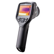
Наилучшее сочетание тепловизионной камеры и встроенной видеокамеры, которое мы когда-либо предлагали в тепловизорах начального уровня.
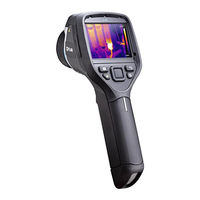
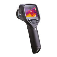
Тепловизор FLIR E50 создан на базе лучших детекторов на VaOx собственного производства FLIR Systems (США) с чувствительностью до 0,05 °C. FLIR E-Series обеспечивает наилучшее качество термограмм при работе по принципу «наведи и сними» в своем ценовом диапазоне. Результат — термограмма с SMX при разрешении — 240×180. Это обеспечивает максимально возможную точность измерений. Потенциальная проблема может быть выявлена быстро, безопасно и со значительного расстояния. Съемка в реальном времени с частотой 60 Гц позволяет снимать движущиеся объекты и процессы в динамике, что невозможно сделать тепловизором с частотой кадров в 9 Гц. Встроенная цифровая камера 3 Мп создает четкие снимки для полных и детализированных отчетов. Убедитесь в этом сами.
В тепловизорах E-Series инструменты для быстрого и профессионального анализа с помощью дисплея Touchscreen, находятся прямо под кончиками ваших пальцев.
Большой дисплей 3.5 дюйма с функцией touchscreen новых тепловизоров E-Series предоставляет простой и легкий доступ ко всем инструментам анализа через простой интуитивно-понятный интерфейс. Используя его, вы можете добавить до 3 точек измерения, что идеально подходит для диагностики 3 фаз электрооборудования. Автоматический расчет разности температур позволяет мгновенно оценить, насколько критичен найденный дефект. Выберите оптимальную цветовую палитру, чтобы сделать дефект наиболее наглядным. Затем можно использовать функцию Thermal Fusion для наложения видимого и ИК изображений для точной привязки положения дефекта. Посмотрите тепловизоры E-series в работе и сделайте для себя правильный выбор.
Впервые в тепловизорах наличие Wi-Fi ускоряет процесс анализа данных, подготовку отчета и возможность передачи результатов.
FLIR сделал шаг вперед, обеспечив возможность подключения тепловизора по Wi-Fi к таким мобильным устройствам как iPad, iPhone, и iPod Touch. Остается только загрузить новое приложение FLIRViewer из Apple Store, и вы уже готовы импортировать термограммы из тепловизора. Никаких кабелей, громоздких ноутбуков, карт памяти. Теперь можно добавить еще больше точек или областей для контроля температуры, можно корректировать настройки и тут же создать отчет. Прямо с мобильного устройства отчет можно отправить тому, кто принимает решение об устранении найденного дефекта по электронной почте. Так, тепловизоры E-Series с Wi-Fi могут сделать работу более быстрой и эффективной.
Устройства с функцией MeterLink упрощают проведение измерений с помощью тепловизоров E-Series.
Будьте уверены, что с помощью функции MeterLink вы не запутаетесь при вводе данных, необходимых для точных измерений. С помощью беспроводного протокола связи Bluetooth все данные об условиях измерений с измерителя влажности или токовых клещей Extec будут переданы непосредственно в тепловизор и сохранены вместе с термограммой. С помощью гарнитуры Bluetooth, которая используется с мобильными телефонами, вы можете записать голосовой комментарий к каждому снимку и затем использовать его при создании отчета.
Инфракрасная камера FLIR E50 сочитает в себе простоту работы и компактность тепловизионной камеры. Она специально разработана, чтобы компактно поместиться в бюджет и разместиться в вашей руке для проведения инспекционной работы. Тепловизор FLIR E50 быстро окупит все затраты, с помощью него можно выявлять электрические, механические проблемы, проблемы ограждающих конструкций здания прежде, чем произойдет сбой в работе или разрушение здания, что повлечет за собой дорогостоящий ремонт.
С инфракрасной камерой FLIR E50 удобно и просто работать, диапазон температур от -20 до +650 °C, точность ±2%, тепловая чувствительность <0.05 °C. Матрица с разрешением 240×180 пикселей обеспечивает прекрасное качество инфрокрасного изображения, а 3-х мегапиксельная цифровая камера видимого спектра позволяет делать съемку в режиме картинка в картинке, это сочетание тепловых и видимых изображений позволяет легко идентифицровать местоположения и более точно офомить тепловизионный отчет. Лазерный указатель помогает точно навести тепловизор на обследуемый объект, а яркая LED лампа обеспечит подсветку даже в самых темных углах. Ручная фокусировка позволяет использовать 4-x кратный цифровой зум и обеспечивает 25°x 19° поле видимости.
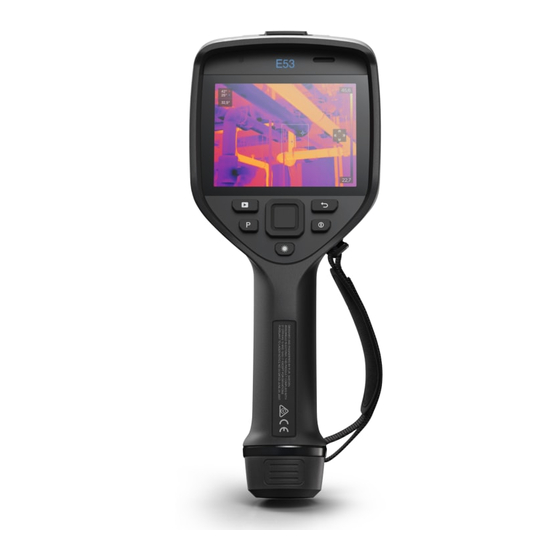
Тепловизор FLIR E 50 оснащен ярким 3.5″ тачскрин экраном, интуитивным интерфейсом, что позволяет в полной мере отоброжать изображение без искажений. Экран так же может использоваться для управления 3 температурными областями и 3 подвижными точками, для получения более детальной информации о температуре объекта на изображении. Композитный видео и mini-USB выходы облегчают получение видео потока. Радиометрические изображения JPEG сохраняются на SD-карте. Функция аннотации позволяет пользователям добавлять голосовые комментарии через гарнитуру Bluetooth и текстовые примечания с помощью тачскрин клавиатуры.
Инфракрасная камера FLIR E50 оборудована продвинутыми коммуникационными решениями.
Тепловизор FLIR E50 может через Wi-Fi коммутироваться с iPad или iPhone с помощью простого приложения FLIR Viewer App от Apple Store. Это позволяет пользователям передавать изображения на девайс, добавлять метки измерений температур, натсраивать температурный диапазон и уровень, изменять палитры, создавать отчеты и легко отправлять по электронной почте результаты, всем заинтересованным лицам для принятия решения. Инфракркрасная камера FLIR E50 имеет функцию MeterLink, чтобы по беспроводной связи передать реальные диагностические данные от токовых клещей и измерителя влажности, непосредственно в тепловизор для уточнения полученных данных, что бы принять квалифицированное решение для устранения проблемы.
Особенности тепловизора Flir E50:
- Высокое качество изображения 43 200 пикселей (240 × 180)
- Тепловая чувствительность 0.05 °C
- 3.5” тачскрин LCD экран
- Ручная фокусировка с 4-х кратным цифровым увеличеием
- Частота кадров 60 Гц
- 3 Мп камера видимого спектра с лампой подсветки
- автоматический/Ручной температурный диапазон
- Стандартная калибровка по температуре 650 °C
- Изотерма, автоматические холодная/горячая маркеры
- Радиометрический/Нерадиометрический IR видео поток
- Лазерный указатель
- Композитный видео и USB-mini выходы
- FLIR Tools софт для обновления программного обеспечения тепловизора
- Функция картинка в картинке
- DeltaT функция температурной разности
- Голосовая и текстовая аннотации
- MeterLink и Wi-Fi для коммутации с различными девайсами для 3 подвижных точки и 3 выделенных области.
Описание
Описание тепловизора FLIR E50:
Инфракрасная камера FLIR E50 сочитает в себе простоту работы и компактность тепловизионной камеры. Она специально разработана, чтобы компактно поместиться в бюджет и разместиться в вашей руке для проведения инспекционной работы. Тепловизор FLIR E50 быстро окупит все затраты, с помощью него можно выявлять электрические, механические проблемы, проблемы ограждающих конструкций здания прежде, чем произойдет сбой в работе или разрушение здания, что повлечет за собой дорогостоящий ремонт.
Тепловизор FLIR E50 внесен в Госреестр СИ РФ (№ 49529-12).
Тепловизор FLIR E50 может через Wi-Fi коммутироваться с iPad или iPhone с помощью простого приложения FLIR Viewer App от Apple Store. Это позволяет пользователям передавать изображения на девайс, добавлять метки измерений температур, настраивать температурный диапазон и уровень, изменять палитры, создавать отчеты и легко отправлять по электронной почте результаты, всем заинтересованным лицам для принятия решения.
Обзор тепловизора FLIR E50:
Отличительные особенности FLIR E50:
- Высокое качество изображения 43 200 пикселей (240 x 180);
- Экран может использоваться для управления 3 температурными областями и 3 подвижными точками, для получения более детальной информации о температуре объекта на изображении;
- Тепловая чувствительность 0,05 °C;
- 3,5” тачскрин LCD экран;
- Ручная фокусировка с 4-х кратным цифровым увеличением;
- Частота кадров 60 Гц;
- 3 Мп камера видимого спектра с лампой подсветки;
- Автоматический/Ручной температурный диапазон;
- Стандартная калибровка по температуре 650 °C;
- Изотерма, автоматические холодная/горячая маркеры;
- Радиометрический/Нерадиометрический IR видео поток;
- Радиометрические изображения JPEG сохраняются на SD-карте;
- Лазерный указатель;
- Композитный видео и USB-mini выходы;
- FLIR Tools софт для обновления программного обеспечения тепловизора;
- Функция аннотации позволяет пользователям добавлять голосовые комментарии через гарнитуру Bluetooth и текстовые примечания с помощью тачскрин клавиатуры;
- Функция картинка в картинке;
- DeltaT функция температурной разности;
- Голосовая и текстовая аннотации;
- MeterLink и Wi-Fi для коммутации с различными девайсами для 3 подвижных точки и 3 выделенных области.
Технические характеристики для тепловизора FLIR E50:
| Параметр | Значение |
|---|---|
| Разрешение | 240 x 180 пикселей |
| Число пикселей | 43 200 |
| Тепловая чувствительность | < 0.05°C |
| Погрешность | ±2% или 2 °C |
| Температурный диапазон | от -20 до +650 °C |
| Поле зрения | 25° x 19° |
| Фокусировка | ручная |
| Функция приближения | 4-х кратное цифровое |
| Тип детектора | Матрица в фокальной плоскости (FPA), неохлаждаемый микроболометр |
| Дисплей | 3.5″ цветной LCD тачскрин экран |
| Дополнительные возможности съемки | лазерная метка, 3-х Мп камера ввидимого спектра, масштабируемая функция картинка в картинке |
| Частота кадров | 60 Гц |
| Видео-выход | Композитный |
| Режим измерения | 3 подвижные точки, 3 выделенные области, функция дельта Т (разности температур) |
| Запись комментариев | Голосовой, текстовый |
| Дополнительные возможности | Wi-Fi совместимость с iPhone/iPad, запись видео в формате MPEG4, Wi-Fi, FLIR tools, Bluetooth совместимость с Smartphone/PC, MeterLink |
| Батарея питания | Заряжаемая Li-Ion батарея (> 4 часов работы) |
Комплект поставки тепловизора FLIR E50:
| № | Наименование | Количество |
|---|---|---|
| 1. | Тепловизор FLIR E50 | 1 |
| 2. | Аккумуляторная батарея | 1 |
| 3. | Блок питания | 1 |
| 4. | Видеокабель | 1 |
| 5. | Кабель USB | 1 |
| 6. | Крышка объектива | 1 |
| 7. | Катра SD | 1 |
| 8. | Ремешок | 1 |
| 9. | Программное обеспечение FLIR Tools RU | 1 |
| 10. | Инструкция по эксплуатации (СD/бумага) | 1 |
| 11. | Сертификат заводской калибровки | 1 |
| 12. | Гарантийный сертификат | 1 |
| 13. | Транспортировочный кейс | 1 |
Товар поставляется под заказ
Внесен в Гос. Реестр РФ
№ 49529-12
Возможность поверки
Заказывается отдельно
Интервал между поверками
1 год
Производитель
Швеция, США
Разрешение детектора
240х180 pix
Компактные и легкие тепловизионные камеры FLIR серии E — идеальное решение для тех, кому важно детальное документирование полученных данных. Для данной линейки характерны высокое разрешение изображения и наличие ряда дополнительных возможностей.
Тепловизор FLIR E50 создан на базе лучших детекторов на VaOx собственного производства FLIR Systems с чувствительностью до 0,05 °C. Тепловизор E-Series обеспечивает наилучшее качество термограмм. Результат — термограмма с SMX при разрешении — 240×180 пикселей. Это обеспечивает максимально возможную точность измерений. Потенциальная проблема может быть выявлена быстро, безопасно и со значительного расстояния. Встроенная цифровая камера 3 Мп создает четкие снимки для полных и детализированных отчетов.
Высокая температурная чувствительность равна 0,045°C и позволяет обнаруживать и визуализировать малейшие перепады температуры в диапазоне от -20°C до +120°C или от 0°C до +650°C. Точность измерений при этом составляет ±2°C или ±2% от абсолютной температуры.
Технические характеристики
| Диапазон измерений | -20…+120°C/0…+650°C |
|---|---|
| Спектральный диапазон | 7,5-13 мкм |
| Температурная чувствительность | <0,05°C |
| Разрешение | 240х180 пикселей |
| Погрешность измерения температуры | ±2°C или ±2% от показания |
| Пространственное разрешение (IFOV) | 1,82 мрад |
| Оптическое поле зрения | 25°х19° |
| Минимальное расстояние фокусировки | 0,4 м |
| Цифровое увеличение | 4х непрерывное цифровое масштабирование |
| Детектор | Микроболометр |
| Голосовая аннотация | 60 секунд через Bluetooth |
| Встроенная цифровая камера | 3,1 мегапикселей и один светодиод |
| Дисплей | Встроенный сенсорный экран, цветной ЖК-дисплей 3,5″, 320х240 пикселей |
| Изотерма | Обнаружение низкой/высокой температуры/интервалов |
| Память | ИК/визуальное изображение; одновременное хранение визуальных и ИК-изображений |
| Частота кадров | 60 Гц |
| Размеры | 246х97х184 мм 560х370х190 мм |
| Рабочая температура | от -15 до +50°C |
| Температура хранения | от +40 до +70°C |
| Масса | 0,825 кг 5,3 кг (брутто) |
| Тип аккумулятора | Ионно-литиевый (с заменой на месте). Время работы-4 часа |
| Зарядка аккумулятора | Встроенная, адаптер переменного тока, двухсекционное зарядное устройство или 12 В из автомобиля |
| Работа от сети переменного тока | Адаптер переменного тока, 90-260 В перем. тока |
| Напряжение адаптера | 12 В пост. тока на выходе |
| Управление питанием | Автоматическое отключение (по выбору пользователя) |
| Защищенность | 25 g (IEC 60068-2-29)/2g(IEC 60068-2-6) |
| Герметичность | IP 54 (IEC 60529) |
| Влагозащищенность | IEC 60068-2-30/24 ч./ при относительной влажности 95%, от +25°C до +40°C/2 цикла |
| Коррекция измерений | Отраженная температура, пропускание оптики и пропускние атмосферы |
| Область | 3 окна с мин./макс./средн. |
| Сравнение температур | Сравнение температур измерений или с заданной температурой |
| Средства настройки изображения | Палитры(Арктика, Полутона, Цвета каления железа, Лава, Радуга, и Радуга НС), корректировка изображений (авто/ручная) |
| Поправка на коэффициент излучения | Варьируется от 0,01 дл 1,0 или выбирается из перечня материалов |
| Режимы изображения | ИК-изображение, галерея пиктограмм |
| Лазерный маркер | Отображается на ИК-изображении |
| Параметры настройки | Локальная настройка единиц измерения, языка, форматов даты и времени; автоматического отключения, яркости экрана |
| Точечные маркеры | 3 |
| USB | USB-A: подключение внешнего USB устройства — USB-mini-Ижпередача данных на/с ПК/потоковое видео MPEG 4 |
| Интерфейсы | мини-USB, USB-A, композитное видео |
| Фокусировка | Вручную |
| Файловые форматы изображений | Стандартный JPEG, включая данные измерений — на карте памяти SD |
| Bluetooth, WiFi | Есть |
| MeterLink | Можно подключить через Bluetooth, гигрометр Extech M0297 или токоизмерительные клещи Extech EX845 |
| Thermal Fusion | Есть |
| Автоматическое обнаружение горячих/холодных участков | Экспонометр автоматически отмечает холодные и горячие места |
| Мгновенный отчет | Нет |
| Текстовая аннотация | Текст из заранее созданного файла или с виртуальной клавиатуры на сенсорном экране |
| Picture-In-Picture (PIP): режим «кадр в кадре» | Масштабируемая ИК-область на визуальном изображении |
Комплект поставки
- тепловизор FLIR E50,
- прочный транспортировочный кейс,
- ИК-камера с объективами,
- аккумулятор,
- ремень,
- диск с ПО FLIR Tools, карта памяти,
- крышка объектива,
- зарядное устройство, USB-кабель,
- пользовательская документация на CD-диске,
- видеокабель.
 |
 |
 |
 |
поверка> оплата> доставка> производитель> сервис>
мы принимаем к оплате наличные (cash) и
![]()
с этим товаром рекомендуем также приобретать
- пленка для определения коэф. излучения полированных поверхностей>
- термометр поверхностный testo 905 T2>
- ИК-окна>