Sometimes it’s hard writing PLC code in LAD (ladder logic) or FBD (function block diagram). Especially, if you have to do some math work or mass operations.
In these cases you can easily use SCL/ST (Structured Control Language/Structured Text.)
 Writing your first TIA code in SCL:
Step 1 – Create or open TIA project
Just like programming LAD or FBD, it’s necessary to create or open a project with a PLC to program in. SCL is supported by all SIMATIC PLCs (S7-300, S7-400, S7-1200 and S7-1500).
In this example, I’ll use a S7-1515-2 PN, but it will also work with other S7-1500 or S7-1200 PLCs.
Step 2 – Add FB/FC
After the project is opened and a PLC is available, we can add a function [FC] or a function block [FB]. The difference between FC and FB is the storage capability. A FB can store data which is still available after a PLC cycle. In our case we only need a FC.
Double click “Add new block” within the “PLC/Program blocks” folder. Now the “Add new block” dialogue is opened. Here we can select the block type to create, in our case FC.
After the block type is chosen, we have to select the language to program in. The drop down list will show all possible programming languages available for the selected block type in combination with the PLC type. We will use “SCL” of course.
If you want, you can also add additional information below in the Additional Information compartment e.g. author, version, etc.. Now we can create the block by click OK in the dialogue.
Step 3 – Modify the block interface
After the block is created, we can modify the Interface of the FC. In our case we will enter an input of type [Array[0..5] of INT], an output of type [INT], and two temp variables of type [INT].
Note: In a FB there is also a static section shown due capability to store data for more than the actual PLC cycle.
Step 4 – Enter SCL code
In the next step we enter the code to determine the maximum value of the array elements. The code will iterate from index zero to five through the array and compare if the actual value is greater than the “tempMax” value. At the end we will get the maximum value contained in the array.
At the line one we set the “tempMax” to a defined value. In this case zero.
In Line three we start the “FOR” loop. This will use the “tempCount” variable to store the actual index of our loop. It is set to zero for the start and will run until it has reached five. So we will run the loop for six times (0->1->2->3->4->5). The code of the “FOR” loop is encapsulated by the “FOR …” statement in line three and “END_FOR;” statement in line seven.
This code block contains an “IF” block which will only process its inner code if the statement “#In[#tempCount] > #tempMax” will return a “TRUE” and so the actual “maxTemp is smaller than the value of the array element with index of #tempCount.
Due to intellisense the TIA portal provides suggestions while typing code. Additional you have a favorite instruction list at the top of the text editor area just like in the editor of the other languages. Here you can add other instructions by drag them from the instructions tab.

Step 5 – Provide some data
To be able to provide our program with some values we have to create a global data block [DB] to provide some data, like we did it for the FC.
We will also enter some startup data, which is provided to the global DB at Startup of the PLC.
Step 6 – Call the FC in OB1
To use the FC in our PLC, we can call the block within the Main [OB1] and provide it with values from the “dbGlobal”. After we added the call, we can compile the program code and load it into our PLC or simulate it with PLCsim.
Step 7 – Testing
After connecting to the device (by selecting the PLC and click “go online”) and activate observe mode in the blocks, we can check the behavior of our program.
We can create a watch table to observe and modify values to test our code. Enter in the column “Modify value” a new value to set and click on the set button in the tool bar. The new value will be set into the variable and the code will process with the new values.
Note: Keep in mind a variable which is set by the PLC program will overwrite the manual set value at every new cycle.
You can modify the display format to e.g. show a variable in hex or binary notation like 16#09 or 2#0000 1001. So it is easier to read e.g. “status words”.
Step 8 – More generic approach
At the block interface it is possible to define the input array with variable limits to offer better reusability for blocks with arrays of different length. Here for we have to adapt the interface at the FC and add code to determine the lower and upper bound of the array. It is also able to do this with multidimensional arrays.
Note: Keep in mind this feature is only available in the newer PLCs (1200/1500).
Pros and cons
| Pro | Con |
| Easy to write complex code | Hard to track signal sequences (reason why it is not used for failsafe PLC coding) |
| Good for mass operations | Bad logically overview |
| Easy programming of switch case | Sometimes hard to read |
Note: You are free to use the programming language of choice which fits best to your needs. In previous courses we saw using SCL networks within FBD code. E.g. program complex code in an SCL Block and interlocking section of Outputs in an FBD Block.
Some other hints
To get an overview over the available commands in the different languages, there is a document from SIEMENS online support which helps me a lot.
- https://support.industry.siemens.com/cs/us/en/view/109778377
Written by Michael Elting
Mechatronics & Automation Engineer and Freelance Writer
Have a question? Join our community of pros to take part in the discussion! You’ll also find all of our automation courses at TheAutomationSchool.com.
Sponsor and Advertise: Get your product or service in front of our 75K followers while also supporting independent automation journalism by sponsoring or advertising with us! Learn more in our Media Guide here, or contact us using this form.
- Author
- Recent Posts
Michael is a freelance writer for The Automation Blog, as well as a degreed engineer of mechatronics, automation engineer, developer, trainer and mentor of internship. Beside his interests in techical topic he is a dedicated hicker and traveler.
Latest posts by Michael Elting (see all)
- S7 PLCsim Advanced — July 20, 2021
- S7 PLCsim — July 19, 2021
- Writing your first TIA code in SCL — April 28, 2021
Search
TIA Portal, SCL
With the recent release of TIA Portal V14 and V14 SP1, several new additions have been added to increase the efficiency and organization of code written in SCL (structured control language).
Recently, I have been using many of these new features while writing code in SCL and wanted to share them with you. We will start by defining SCL and its uses in programming, then we will compare ladder to SCL, next we will discuss inline SCL networks, Regions and Region Synchronization, and will finish by reviewing the streamlined Surround With…
What is SCL and When Should I Program Using it?
SCL stands for Structured Control Language and is a text-based form of programming Siemens PLCs.
SCL opens up several new constructs that are unavailable while programming in conventional ladder logic, including the FOR and WHILE loops as well as the CASE statement. These are particularly useful when dealing with large amounts of data in an array form. Using SCL also increases the readability of any sort of arithmetic calculation.
What Does SCL Look Like?
Below is an example of code written in both ladder and SCL to accomplish the same result.
Ladder Logic
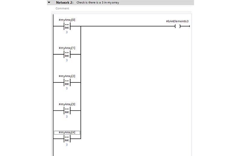
I have created an array of five integers and I would like to check and see if any indexes of my array are equal to three. In order to get this information in a single scan of my logic, in Ladder, I would need to check each index individually to determine if any of them are equal to 3.
For a small array, writing this code in ladder logic doesn’t seem so bad. However, imagine I had an array of a hundred or even a thousand integers and I needed to check all them.
SCL
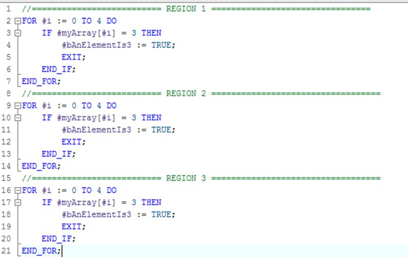
Examining SCL logic, suddenly, the ladder logic solution seems inefficient in comparison. Using a combination of a FOR loop, IF statement and an EXIT, I can easily check an array of any size in a single scan.
If my application required, I could even nest FOR loops within each other in order to check or set values of a UDT which contains an array of variables.
Inline SCL Networks
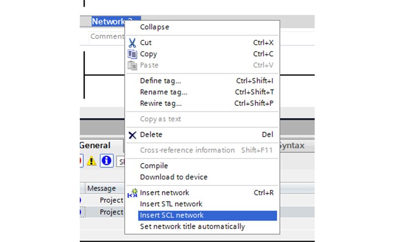
In TIA Portal V14, there is now the ability to create function blocks and function calls that contain code written in both LAD and SCL. An SCL network can easily be inserted into a function without the need to create a separate SCL function.
For example, it was previously necessary to use LAD math operations or a separate SCL function to string together a complex calculation that can now easily be written in an SCL network.
Regions
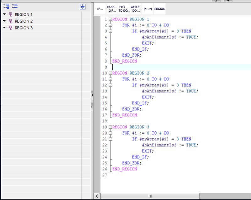
- Regions are a new SCL organizational tool that provides a similar level of organization as a network does in a LAD function.
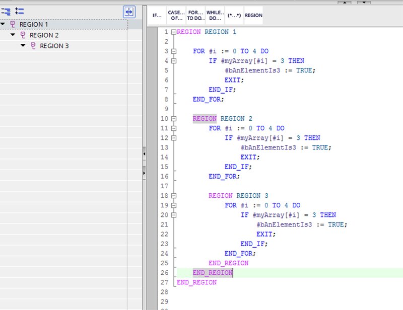
- Regions are collapsible and easy to navigate through the sidebar.
- Regions can be nested, if needed, to provide an even greater level of organization.
- Keep in mind that regions cannot cross logical boundaries. For example, if a region begins inside one case of a case statement, it must also end in the same case. Failure to do so will result in a compiler error.
- Regions make lines of comments that serve only as a separator for a new section of code unnecessary.
BEFORE
AFTER
Synchronizing Regions
- The sidebar navigation that shows the regions in an SCL function can also be set to be synchronized with the code. This means that when expanding or contracting a region in the sidebar, the body of code will reflect the change.
- With synchronization turned on, large bodies of SCL code can easily be minimized or maximized without heavy use of the scroll wheel to find where a region starts.
- Keep in mind that logical statements like IF…THEN… can also be expanded or contracted but are not synchronized with the region they are within.
SYNCRONIZED, COLLAPSED
SYNCRONIZED, ALL EXPANDED (NESTED REGIONS)
Surround With
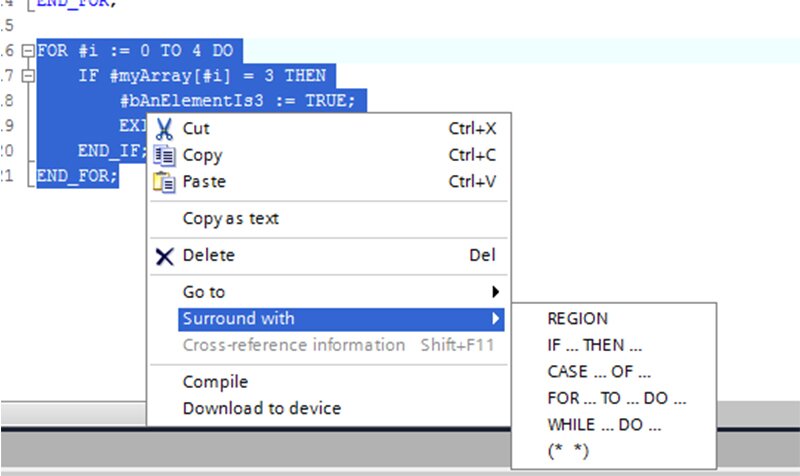
As of V14 SP1, the ability to add logical statements, regions, and comments to existing code has been greatly streamlined with the addition of the “Surround with…” option.
Simply highlight a body of code, right-click it and choose what you would like to surround it with. This is especially helpful for quickly adding regions to code written previously to V14 or to quickly comment out chunks of code while debugging.
Hopefully, some of these tips will allow you to create more efficient PLC code and increase your development speed at the same time.
If you are in need of DMC’s expertise, check out our Siemens PLC Programming Services or Contact Us to get started on a project today.
Comments
Friday, June 22, 2018 12:58 PM
The else part in the SCL code is missing. bAnElementIs3 will become FALSE in Ladder if all array elements are FALSE.
In SCL bAnElementIs3 will stay TRUE if all array elements are FALSE again.
Wednesday, April 11, 2018 12:09 AM
Mr David,
Sir please help me out, I need a Direct On Line (DOL) program in SCL, and Forward Reverse SCL program.
I will be very happy sir if can help out.
Thanks in advance
Thursday, January 4, 2018 1:31 PM
Luciano,
There is no way to convert an compiled STL program into SCL. For a conversion I was able to reverse engineer some STL files into SCL, but it is a very difficult and intensive process.
If the OEM will not provide the original SCL, and it wasn’t loaded onto the controller (which is rare) then you are unfortunately out of luck.
Thursday, January 4, 2018 9:12 AM
Hi Luciano,
What version of TIA Portal are you using and what type of controller?
Wednesday, January 3, 2018 4:23 AM
Dear David, Do you know a way to revert a program made using SCL language back to it original form ? I have a source program, some file used SCL but the supplier delivered just the STL converted form. Now, I want to study the program, but a compiled SCL into STL is very difficult to understand.
Do you know a way to revert back to it SCL form ?
Предложите, как улучшить StudyLib
(Для жалоб на нарушения авторских прав, используйте
другую форму
)
Ваш е-мэйл
Заполните, если хотите получить ответ
Оцените наш проект
1
2
3
4
5


 Writing your first TIA code in SCL:


