MAXtream TDMA
23 дБи направленная антенна высокого усиления и надёжная конструкция для беспроводной передачи данных на большие расстояния
-

23 дБи направленная
антенна -
Простая сборка
и удобная установка -
Ветроустойчивая
конструкция -
Всепогодный корпус
класса IP65 -
Защита от электростатического разряда
до 15 кВ и защита от удара молнии до 6 кВ


23 дБи направленная антенна для
передачи данных на большие расстояния
Благодаря 23 дБи направленной антенне высокого усиления с технологией и металлическому экранированию CPE605 обеспечивает отличную направленность луча, уменьшает задержки и поглощает шумы. Высокая производительность в сочетании с удобным дизайном делают точку доступа CPE605 бюджетным и качественным решением для организации беспроводного подключения вне помещения на расстояние до 20 км.
Надёжная конструкция и удобная установка
- Облучатель
- Боковая
отражающая панель - Центральная
отражающая панель - Боковая
отражающая панель
Установка на мачте
Крепление для облучателя
- Фиксирующий механизм для простой сборки
- Комплект для установки на мачте и возможность трёхосевого выравнивания для удобного монтажа
- Прочная конструкция обеспечивает стабильную работу при сильном ветре
Компактная
и лёгкая упаковка
Малогабаритные и лёгкие упаковки –
основа выгодной логистики и розничной торговли
15,5 см
0 см
0 см
32,8 см
0 см
32,5 см
0 см
14,2 см
Pharos Control – утилита для управления сетью
Точки доступа CPE605 оборудованы централизованным ПО для управления сетью — Pharos Control, которое позволяет легко управлять всеми устройствами в сети с одного ПК. Обнаружение, мониторинг состояния, обновление встроенного ПО, а также другие функции управления сетью могут выполняться с помощью Pharos Control. Интуитивный веб-интерфейс Pharos предоставляет альтернативный метод управления сетью и позволяет профессиональным пользователям выполнять более детальные настройки.
Посмотреть инструкция для TP-Link CPE605 бесплатно. Руководство относится к категории точки доступа, 1 человек(а) дали ему среднюю оценку 7.5. Руководство доступно на следующих языках: английский. У вас есть вопрос о TP-Link CPE605 или вам нужна помощь? Задайте свой вопрос здесь
Не можете найти ответ на свой вопрос в руководстве? Вы можете найти ответ на свой вопрос ниже, в разделе часто задаваемых вопросов о TP-Link CPE605.
Какие сертификаты TP-Link CPE605 имеет?
Какая высота TP-Link CPE605?
Какая ширина TP-Link CPE605?
Какая толщина TP-Link CPE605?
Инструкция TP-Link CPE605 доступно в русский?
Не нашли свой вопрос? Задайте свой вопрос здесь
![]()
User Guide
For TP-Link Pharos Series Products
CPE210 / CPE220 / CPE510 / CPE520 / CPE605 / CPE610
WBS210 / WBS510
1910012554 REV 3.1.0
March 2019
|
CONTENTS |
||
|
About this User Guide…………………………………………………………………………………………… |
1 |
|
|
Overview…………………………………………………………………………………………………………………. |
2 |
|
|
1 Operation Modes…………………………………………………………………………………………….. |
3 |
|
|
1.1 |
Access Point………………………………………………………………………………………………………………………………. |
4 |
|
1.2 |
Client…………………………………………………………………………………………………………………………………………… |
5 |
|
1.3 |
Repeater (Range Extender)……………………………………………………………………………………………………… |
6 |
|
1.4 |
Bridge………………………………………………………………………………………………………………………………………….. |
7 |
|
1.5 |
AP Router……………………………………………………………………………………………………………………………………. |
7 |
|
1.6 |
AP Client Router (WISP Client)………………………………………………………………………………………………… |
8 |
|
2 Quick Start………………………………………………………………………………………………………… |
9 |
|
|
2.1 |
Check the System Requirements…………………………………………………………………………………………. |
10 |
|
2.2 |
Log In to the Device………………………………………………………………………………………………………………… |
10 |
|
2.3 |
Set Up the Wireless Network………………………………………………………………………………………………… |
11 |
|
Access Point………………………………………………………………………………………………………………………………… |
12 |
|
|
Client ……………………………………………………………………………………………………………………………………………. |
16 |
|
|
Repeater (Range Extender)……………………………………………………………………………………………………….. |
19 |
|
|
Bridge……………………………………………………………………………………………………………………………………………. |
23 |
|
|
AP Router……………………………………………………………………………………………………………………………………… |
27 |
|
|
AP Client Router (WISP Client)………………………………………………………………………………………………….. |
32 |
|
|
3 Monitor the Network……………………………………………………………………………………… |
38 |
|
|
3.1 |
View the Device Information…………………………………………………………………………………………………. |
39 |
|
3.2 |
View the Wireless Settings……………………………………………………………………………………………………. |
39 |
|
3.3 |
View Wireless Signal Quality…………………………………………………………………………………………………. |
40 |
|
3.4 |
View Radio Status……………………………………………………………………………………………………………………. |
41 |
|
3.5 |
View the LAN Settings……………………………………………………………………………………………………………. |
43 |
|
3.6 |
View the WAN Settings…………………………………………………………………………………………………………… |
43 |
|
3.7 |
Monitor Throughput……………………………………………………………………………………………………………….. |
44 |
|
3.8 |
Monitor Stations……………………………………………………………………………………………………………………… |
44 |
|
3.9 |
Monitor Interfaces…………………………………………………………………………………………………………………… |
45 |
|
3.10 |
Monitor ARP Table…………………………………………………………………………………………………………………… |
46 |
|
3.11 |
Monitor Routes………………………………………………………………………………………………………………………… |
46 |
|
3.12 |
Monitor DHCP Clients…………………………………………………………………………………………………………….. |
47 |
|
3.13 |
Monitor Dynamic WAN……………………………………………………………………………………………………………. |
47 |
|
4 Configure the Network…………………………………………………………………………………. |
49 |
|
|
4.1 |
Configure WAN Parameters………………………………………………………………………………………………….. |
50 |
|
4.2 |
Configure LAN Parameters……………………………………………………………………………………………………. |
57 |
|
Access Point/Client/Repeater/Bridge Mode………………………………………………………………………….. |
57 |
|
|
AP Router/AP Client Router Mode…………………………………………………………………………………………… |
60 |
|
|
4.3 |
Configure Management VLAN………………………………………………………………………………………………. |
62 |
|
4.4 |
Configure the Forwarding Feature……………………………………………………………………………………….. |
62 |
|
4.5 |
Configure the Security Feature…………………………………………………………………………………………….. |
66 |
|
4.6 |
Configure Access Control……………………………………………………………………………………………………… |
69 |
|
4.7 |
Configure Static Routing……………………………………………………………………………………………………….. |
70 |
|
4.8 |
Configure Bandwidth Control……………………………………………………………………………………………….. |
71 |
|
4.9 |
Configure IP & MAC Binding………………………………………………………………………………………………….. |
73 |
|
5 Configure the Wireless Parameters……………………………………………………………. |
75 |
|
|
5.1 |
Configure Basic Wireless Parameters…………………………………………………………………………………. |
76 |
|
5.2 |
Configure Wireless Client Parameters………………………………………………………………………………… |
78 |
|
5.3 |
Configure Wireless AP Parameters……………………………………………………………………………………… |
82 |
|
5.4 |
Configure Multi-SSID……………………………………………………………………………………………………………… |
88 |
|
5.5 |
Configure Wireless MAC Filtering………………………………………………………………………………………… |
90 |
|
5.6 |
Configure Advanced Wireless Parameters………………………………………………………………………… |
91 |
|
6 Manage the Device………………………………………………………………………………………… |
94 |
|
6.1 Manage System Logs |
………………………………………………………………………………………………………………95 |
|
6.2 |
Specify the Miscellaneous Parameters |
………………………………………………………………………………..96 |
|
6.3 |
Configure Ping Watch Dog…………………………………………………………………………………………………….. |
97 |
|
6.4 |
Configure Dynamic DNS………………………………………………………………………………………………………… |
98 |
|
6.5 |
Configure Web Server……………………………………………………………………………………………………………. |
99 |
|
6.6 |
Configure SNMP Agent……………………………………………………………………………………………………….. |
100 |
|
6.7 |
Configure SSH Server………………………………………………………………………………………………………….. |
102 |
|
6.8 |
Configure RSSI LED Thresholds………………………………………………………………………………………… |
102 |
|
7 Configure the System………………………………………………………………………………… |
104 |
|
|
7.1 |
Configure Device Information……………………………………………………………………………………………. |
105 |
|
7.2 |
Configure Location Information…………………………………………………………………………………………. |
105 |
|
7.3 |
Configure User Account……………………………………………………………………………………………………… |
105 |
|
7.4 |
Configure Time Settings……………………………………………………………………………………………………… |
106 |
|
7.5 |
Update Firmware…………………………………………………………………………………………………………………… |
108 |
|
7.6 |
Configure Other Settings……………………………………………………………………………………………………. |
109 |
|
8 Use the System Tools………………………………………………………………………………… |
110 |
|
|
8.1 |
Configure Ping………………………………………………………………………………………………………………………. |
111 |
|
8.2 |
Configure Traceroute………………………………………………………………………………………………………….. |
111 |
|
8.3 |
Test Speed…………………………………………………………………………………………………………………………….. |
112 |
|
8.4 |
Survey…………………………………………………………………………………………………………………………………….. |
113 |
|
8.5 |
Analyze Spectrum………………………………………………………………………………………………………………… |
115 |
About this User Guide
This User Guide contains information for setup and management of TP-Link Pharos series products. Please read this guide carefully before operation.
When using this guide, please notice that features of the product may vary slightly depending on the model and software version you have, and on your location, language, and internet service provider. All screenshots, images, parameters and descriptions documented in this guide are used for demonstration only.
Some models featured in this guide may be unavailable in your country or region. For local sales information, visit http://www.tp-link.com.
The information in this document is subject to change without notice. Every effort has been made in the preparation of this document to ensure the accuracy of the contents, but all statements, information, and recommendations in this document do not constitute the warranty of any kind, express or implied. Users must take full responsibility for their application of any products.
Convention
Unless otherwise noted, the introduction in this guide takes CPE510 as an example.
More Info
The latest software, management app and utility can be found at Download Center at https://www.tp-link.com/support.
The Quick Installation Guide can be found where you find this guide or inside the package of the product.
Specifications can be found on the product page at https://www.tp-link.com.
Our Technical Support contact information can be found at the Contact Technical Support page at https://www.tp-link.com/support.
To ask questions, find answers, and communicate with TP-Link users or engineers, please visit https://community.tp-link.com to join TP-Link Community.
1

Overview


 is TP-Link’s next generation outdoor product series dedicated to long-distance outdoor wireless networking solutions.


 is a powerful Web-based operating system, which is integrated into all Pharos series products.
New features of Pharos series products are listed as follows:
•Provides User-friendly UI design.
•TP-Link Pharos MAXtream (Time-Division-Multiple-Access) technology improves product performance in throughput, capacity and latency, which are ideal for point-to-multipoint applications.
•Supports multiple operation modes: Access Point, Client, Repeater (Range Extender), Bridge, AP Router and AP Client Router (WISP Client).
•Provides system-level optimization for long-distance wireless transmission.
•Supports selectable bandwidth of 5/10/20/40MHz.
•Supports easy antenna alignment with Wireless Signal Indicators on Web interface.
•Provides Throughput Monitor, Spectrum Analyzer, Speed Test and Ping tools.
•Supports discovery and management via Pharos Control application.
2

1 Operation Modes
The Pharos series products support six operation modes to satisfy user’s diversified network requirements. This chapter introduces typical usage scenarios of different modes, including:
1.1Access Point
1.2Client
1.3Repeater (Range Extender)
1.4Bridge
1.5AP Router
1.6AP Client Router (WISP Client)
3
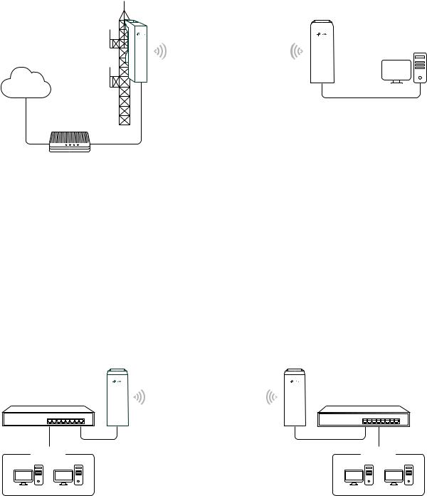
1.1 Access Point
In AP mode, the device acts as a central hub and provides wireless access point for wireless clients, thus the AP mode is applicable to the following three scenarios. Meanwhile, Multi-SSID function can be enabled in this mode, providing up to four wireless networks with different SSIDs and passwords.
Scenario 1
|
Access Point |
AP Client Router |
|||||
|
LAN: 192.168.7.2 |
LAN: 192.168.0.254 |
|||||
|
WAN: Dynamic IP |
||||||
Internet
Router
LAN: 192.168.7.1
Network requirements: Establish the network coverage in the remote areas without longdistance cabling.
The device in the network: In the adjacent town covered by wired network, ISP (Internet Service Provider) can put up a device in AP mode to access the internet and transform wired signal into wireless one. In the remote area, users can put up a device in AP Client Router mode to access the wireless network.
Advantages: Transmit data wirelessly across a long distance and reduce the cabling cost.
|
|
|
|
Scenario 2 |
|
|
Access Point |
Client |
|
LAN: 192.168.0.254 |
LAN: 192.168.0.2 |
|
Switch |
Switch |
4
Network requirements: Combine two separate office networks into one.
The device in the network: The device in AP mode connects to one office network and creates a wireless network. The device in Client mode connects to the other office network and the wireless network.
Advantages: Establish a point-to-point WLAN across a long distance to achieve the connectivity between two networks and avoid the cabling trouble.
Scenario 3
|
Access Point |
Laptop/Tablet/Smartphone |
|
|
Internet |
Wired Local |
|
|
Area Network |
Network requirements: Establish wireless network coverage in the campus, community, industrial park or public place to provide wireless access for users.
The device in the network: With the access to campus wired network or other wired local area networks, the device in AP mode provides the wireless access for wireless clients, such as smart phones, laptops and tablets to connect to the network.
Advantages: Enrich the access ways of local area network and extend the network coverage.
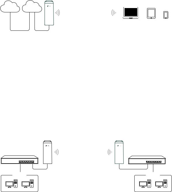
1.2 Client
For the device in Client mode, the most common usage scenario is point-to-point networking. The device is used to transform wireless signal into wired one.
|
Access Point |
Client |
|
LAN: 192.168.0.254 |
LAN: 192.168.0.2 |
|
Switch |
Switch |
5
Network requirements: Help the wired devices to connect to the wireless network.
The device in the network: In Client mode, the device actually serves as a wireless adapter to receive the wireless signal from root AP or Station. In this case, wired devices can access the wireless network by connecting to the device in Client mode.
1.3 Repeater (Range Extender)
The device in Repeater mode can extend wireless coverage of an existing wireless network. The SSID and encryption type of the device should be the same as those of the root AP.
|
Access Point |
Repeater |
Client |
|
|
LAN: 192.168.0.254 |
LAN: 192.168.0.2 |
LAN: 192.168.0.3 |
|
|
Switch |
SSID:abc |
SSID: abc |
Switch |
Network requirements: Repeat wireless signal and extend the wireless network coverage.
The device in the network: If you want to combine two networks via wireless connection but the distance is beyond the networks’ wireless coverage range, you can put one or more devices in Repeater mode along the path to repeat the wireless signal and extend the wireless transmission range.
6
![]()
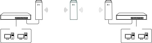
1.4 Bridge
The device in Bridge mode can extend wireless coverage of an existing wireless network. The SSID and encryption type of the device can be different from those of root AP.
|
Access Point |
Bridge |
Client |
|
|
LAN: 192.168.0.254 |
LAN: 192.168.0.2 |
LAN: 192.168.0.3 |
|
|
Switch |
SSID:abc |
SSID: 123 |
Switch |
Network requirements: Extend the wireless network to eliminate the wireless signal-blind areas. Users can use different SSID and encryption type from those of the root AP device to access the network.
The device in the network: Similar to the Repeater mode, the Bridge mode is used to enhance the exiting wireless signal. However, the difference is that the extended wireless network has its own SSID and encryption type different from those of root AP.
1.5 AP Router
The device in AP Router mode serves as a normal home wireless router but provides a wider wireless network range.
|
AP Router |
Laptop/Tablet/Smartphone |
Internet
Modem
Network requirements: Establish the wireless network coverage in the campus, community, industrial park or other public places and so on.
The device in the network: The device in AP Router mode connects to root ADSL/Cable
7
Modem for internet access. Meanwhile, it creates a wireless network for the wireless clients to connect to the internet.
Note
In this mode, the device cannot be managed directly through the port connected to ADSL/Cable Modem. To manage the device, you can connect the management host to the device wirelessly or via the other LAN port.
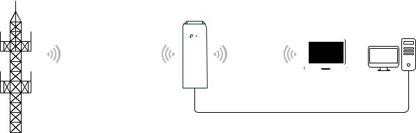
1.6 AP Client Router (WISP Client)
In AP Client Router mode, the device access the internet provided by WISP (Wireless Internet Service Provider) through wireless connection. For the downstream clients, the device serves as a normal home wireless router. It can provide wired connection and wireless connection simultaneously.
|
WISP |
AP Client Router |
|||
|
LAN: 192.168.0.254 |
||||
|
WAN: Dynamic IP |
||||
|
WISP’s network |
User Network |
Network requirements: Get internet service from WISP.
The device in the network: The device in Client Router Mode connects to WISP wirelessly for internet service. It provides both wired access and wireless access for the clients.
8

2 Quick Start
This chapter introduces how to quickly build a wireless network in different operation modes. Follow the steps below:
2.1Check the System Requirements
2.2Log In to the Device
2.3Set Up the Wireless Network
9
2.1 Check the System Requirements
Operating System:
Microsoft Windows XP, Windows Vista, Windows 7, Windows 8, Windows 10, Linux, or Mac OS X.
Web Browser
Google Chrome, Safari, Firefox, and Apple Safari. IE browsers are not recommended.
2.2 Log In to the Device
Before configuring the device, you need to access the PharOS configuration interface. Follow the steps below:
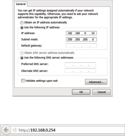
1. Connect your PC to the device.
2. Set the IP address of your PC as static IP address on 192.168.0.X subnet (X ranges from 2 to 253, e.g.192.168.0.10).
3. Launch a web browser on and enter the management IP address of the device (192.168.0.254 by default) in the address bar to load the login page of the PharOS configuration interface.
10
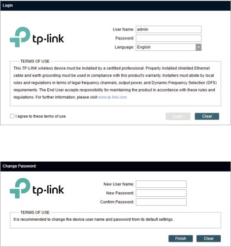
4. Use admin for both of User Name and Password. Select the appropriate language from the Language drop-down list. Read and agree the terms of use, then click Login.
5. Create a new username and password for network security. Click Finish to log in to the PharOS.
2.3 Set Up the Wireless Network
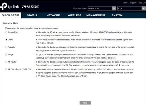
You can use the Quick Setup wizard to quickly configure your device step by step. Choose the suitable operation mode according to your network environment and follow the step- by-step instructions.
11
Access Point
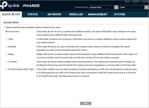
Follow the steps below to configure the device as Access Point mode:
1. Go to the QUICK SETUP page, select Access Point and click Next.
12
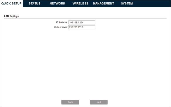
2. In the LAN Settings section, specify the LAN IP address and the Subnet Mask for the device. Then, click Next.
13
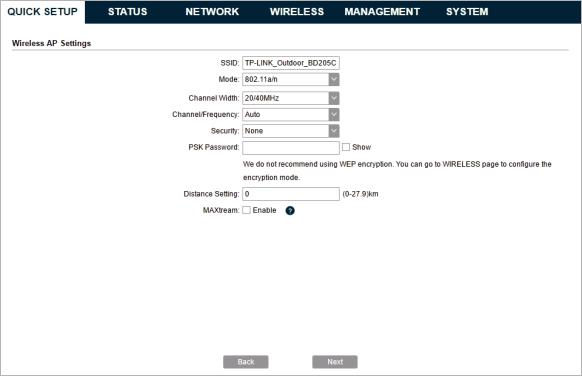
3. In the Wireless AP Settings section, specify the basic wireless parameters to create a wireless network. Click Next.
Tips
··It is recommended to specify Security as WPA-PSK/WPA2-PSK for the network security.
··You can keep the default settings or specify the parameters according to your need. For details, refer to 5. Configure the Wireless Parameters.
14
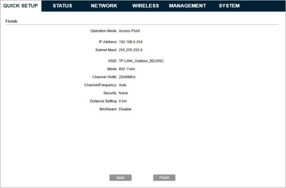
4. In the Finish section, review the configurations and click Finish to complete the quick setup.
5. Connect the device according to your network topology and use it normally.
15
Client
Follow the steps below to configure the device as Client mode:
1. Go to the QUICK SETUP page, select Client and click Next.
16
![]()
2. In the LAN Settings section, specify the LAN IP Address and the Subnet Mask for the device. Then, click Next.
3. In the Wireless Client Settings section, click Survey to search for the upstream wireless network.
4. Select the desired wireless network and click Connect.
17

Tips
There may be two or more networks with the same SSID in the AP list. Click Lock to AP to select the SSID and AP simultaneously, which can make the device connect to the specific AP next time.
5. In the Wireless Client Settings section, specify the wireless parameters to connect to the specified wireless network. Click Next.
Note
Make sure that Security and PSK Password are the same as the upstream wireless network’s. Other parameters set in this page and those of the upstream wireless network should be compatible with each other. For details, refer to 5. Configure the Wireless Parameters.
18
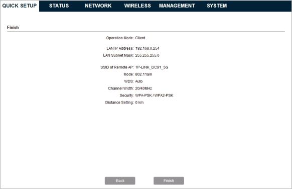
6. In the Finish section, review the configurations and click Finish to complete the quick setup.
7. Connect the device according to your network topology and use it normally.
Repeater (Range Extender)
Follow the steps below to configure the device as Repeater (Range Extender) mode:
19

1. Go to the QUICK SETUP page, select Repeater and click Next.
2. In the LAN Settings section, specify the LAN IP address and the Subnet Mask for the device. Then, click Next.
20
3. In the Wireless Client Settings section, click Survey to search for the upstream wireless network.
4. Select the desired wireless network and click Connect.
Tips
There may be two or more networks with the same SSID in the AP list. Click Lock to AP to select the SSID and AP simultaneously, which can make the device connect to the specific AP next time.
5. In the Wireless Client Settings section, specify the wireless parameters to connect to the specified wireless network. Click Next.
21
Note
Make sure that Security and PSK Password are the same as the upstream wireless network’s. Other parameters set in this page and those of the upstream wireless network should be compatible with each other. For details, refer to 5. Configure the Wireless Parameters.
6. In the Finish section, review the configurations and click Finish to complete the quick setup.
22
7. Connect the device according to your network topology and use it normally.
Bridge
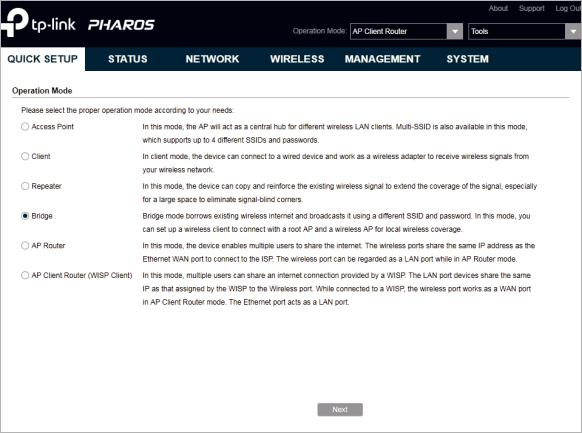
Follow the steps below to configure the device as Bridge mode:
1. Go to the QUICK SETUP page, select Bridge and click Next.
23
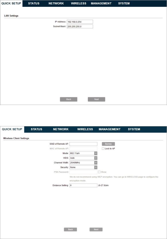
2. In the LAN Settings section, specify the LAN IP address and the Subnet Mask for the device. Then, click Next.
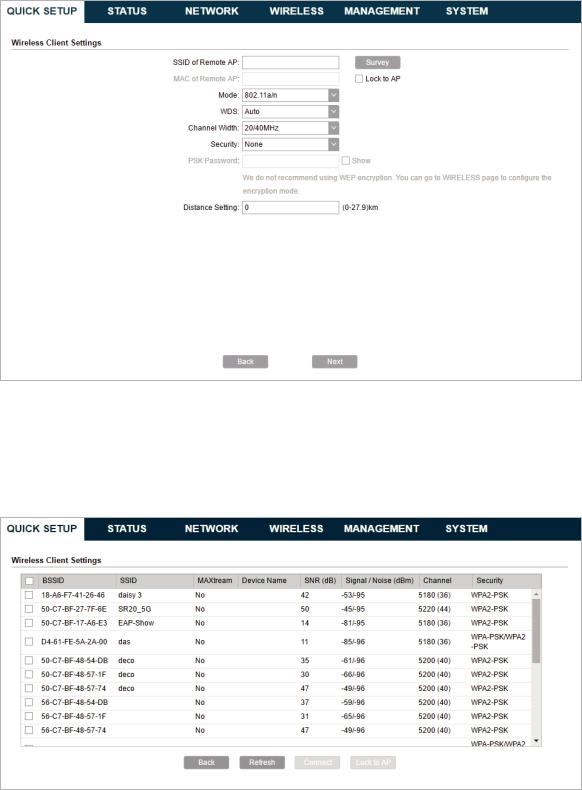
3. In the Wireless Client Settings section, click Survey to search for the upstream wireless network.
4. Select the desired wireless network and click Connect.
24
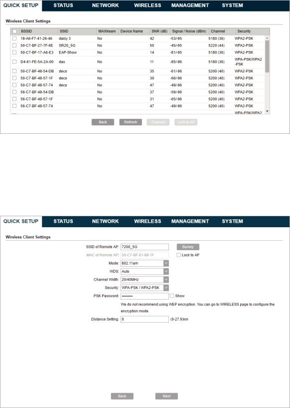
Tips
There may be two or more networks with the same SSID in the AP list. Click Lock to AP to select the SSID and AP simultaneously, which can make the device connect to the specific AP next time.
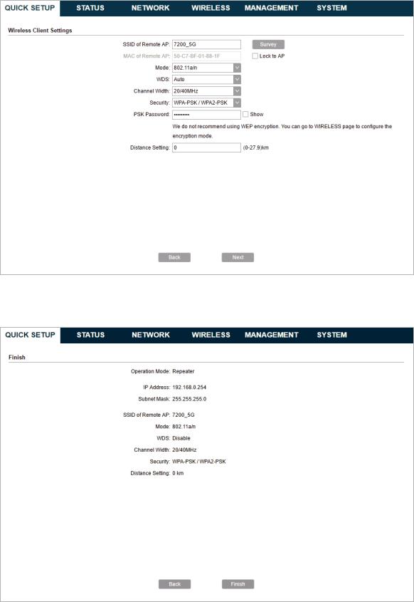
5. In the Wireless Client Settings section, specify the wireless parameters to connect to the specified wireless network. Click Next.
Note
Make sure that the Security and PSK Password are the same as the upstream wireless network’s. Other parameters set in this page and those of the upstream wireless network should be compatible with each other. For details, refer to 5. Configure the Wireless Parameters.
25
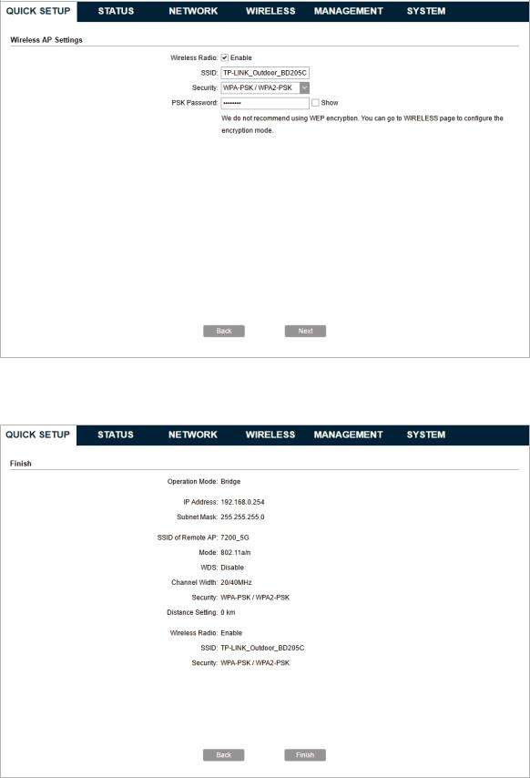
6. In the Wireless AP Settings section, specify the parameters to create a new wireless network for the downstream clients. Click Next.
7. In the Finish section, review the configurations and click Finish to complete the quick setup.
8. Connect the device according to your network topology and use it normally.
26
![]()
AP Router
Follow the steps below to configure the device as AP Router mode:
1. Go to the QUICK SETUP page, select AP Router and click Next.
27

2. In the WAN Connection Type section, specify the connection type according to your need and click Next.
The device supports three types of the WAN connection, including PPPoE, Dynamic IP and Static IP. You can contact with your ISP to confirm your WAN connection type.
28

PPPoE
Select PPPoE and click Next, then the following page will appear. In the WAN Settings section, specify the parameters that are provided by your ISP and click Next.
Dynamic IP
Select Dynamic IP and click Next. In this type, the device will obtain a WAN connection automatically without any WAN configurations.
29

Static IP
Select Static IP and click Next, then the following page will appear. In the WAN Settings section, specify the parameters that are provided by your ISP and click Next.
3. In the Wireless AP Settings section, specify the basic wireless parameters to create a wireless network. Click Next.
30

Tips
··It is recommended to specify Security as WPA-PSK/WPA2-PSK for the network security.
··You can keep the default settings or specify the parameters according to your need. For details, refer to 5. Configure the Wireless Parameters.
4. In the Finish section, review the configurations and click Finish to complete the quick setup.
31

5. Connect the device according to your network topology and use it normally.
AP Client Router (WISP Client)
Follow the steps below to configure the device as AP Client Router (WISP Client) mode:
1. Go to the QUICK SETUP page, select AP Client Router (WISP Client) and click Next.
32
 Loading…
Table of Contents for TP-Link CPE605:
-
03 • Panel Layout On: A device is connected to the ETHERNET port, but there is no activity. Flashing: A device is connected to the ETHERNET port and is active. On: The CPE is powered on. On: The wireless function is enabled. RESET Press and hold for 5 seconds to reset the CPE to its factory defaults. ETHERNET The port is used to connect to the POE port of the provided PoE adapter for both data transmission and power supply through Ethernet cabling. • Passive PoE Adapter Power LED
-
Installation Guide Outdoor CPE Get Started with Setup Videos Scan the QR code or visit https://www.tp-link.com/support/setup-video/
-
09 b. Attach the Rear Cover to the reector assembly. Press upon the Rear Cover at the four positions marked in the diagram below in sequence until it locks into place. 1 2 4 3 WARNING:To avoid damage, do not place the panels on a at surface or push down on it.
-
20 Antenna Alignment In order to get the best performance, you can precisely align the direction of the CPE with the assistance of Wireless Signal Quality on the STATUS page of the PharOS Web Interface. Adjust the direction of the CPE until the SNR reaches a maximum. WBS+Antenna WBS+Antenna
-
16 Installer Compliance Responsibility Devices must be professionally installed and it is the professional installer’s responsibility to make sure the device is operated within local rules and regulations. Since TP-Link’s Pharos outdoor CPE can be paired with a variety of antennas, the Antenna and Transmit Power elds are provided to the professional installer to assist in meeting regulatory requirements. Refer to Antenna and Transmit Power
-
04 Application Example The CPE device with the reector installed provides outdoor network access over long distances for point-to-point applications. The CPE device without the reector installed provides outdoor -to-indoor Wi-Fi coverage with the Feed only mode.
-
12 6. Secure the Mounting Bracket to the Rear Cover using M6x79 Hexagon Bolts with Wing Nut and Lock Washer Assemblies. 7. Attach the CPE assembly to the pole using the metal Strap. a. Open the Mental Strap and feed it through the two slots of the Ball joint Mount.
-
07 Hardware Installation TERMS OF USE: TP-Link’s Pharos series outdoor CPEs must be installed by a certied professional. Installers must abide by local rules and regulations in terms of legal frequency channels, output power, and Dynamic Frequency Selection (DFS) requirements. 1. Attach the Side Reector Panels to the Center Reector Panel as follows: a. Insert the two mounting studs on the Center Reector Panel into the large opening of the slots on the Side Reector Panel. b. Slide the Side Reector Panel until the mo
-
01 Overview TP-Link’s Pharos series outdoor CPEs are dedicated to outdoor wireless network solutions. Package Contents Installation Guide Outdoor CPE Pharos CPE Rear Cover Center Reector Panel Side Reector Panels (Qty.2) Mounting Bracket (For CPE) Protective Cap Power CordHexagon Bolts with Wing Nut and Washer Assemblies (M6x79) Metal Strap Mounting Brac
-
14 Power Supply • Connecting the PoE Adapter Connect the devices as shown in the gure below. PoE LAN Ethernet cable length up to 60m • Mounting the PoE Adapter (Optional) Note: To ensure the passive PoE adapter is attached most securely, it is recommended to install the adapter with the Ethernet port facing upward. 1. Drill two holes on the wall and insert the plastic wall anchors into the the holes. Secure the mounting bracket to the wall.
-
Safety Information • Keep the device away from water, re, humidity or hot environments. • Do not attempt to disassemble, repair, or modify the device. • Do not use damaged charger or USB cable to charge the device. • Do not use any other chargers than those recommended. • Do not use the device where wireless devices are not allowed. • Adapter shall be installed near the equipment and shall be easily accessible. The products of TP-Link partly contain software
-
08 c. Repeat step a and step b to attach the other Side Reector Panel. d. Attach the Side Reector Panels to the Center Reector Panel more securely using four M2.5*8 combination screws with M2.5*2 nuts (only provided with CPE710). 2. Attach the Rear Cover to the reector assembly as follows: a. While holding the reector assembly, align the raised edges on the back with the Securing Arms of the R
Questions, Opinions and Exploitation Impressions:
You can ask a question, express your opinion or share our experience of TP-Link CPE605 device using right now.
|
Detail Specifications: 1665/1665946-cpe605.pdf file (04 Dec 2022) |
Accompanying Data:
TP-Link CPE605 Wireless Access Point PDF Installation Manual (Updated: Sunday 4th of December 2022 03:01:55 AM)
Rating: 4.9 (rated by 39 users)
Compatible devices: TL-WA3001, AURANET CAP300-Outdoor, Omada EAP610, TL-WA701ND, AP300 V1, TL-WA801N, AURANET EAP110-Outdoor, WA801ND.
Recommended Documentation:
Text Version of Installation Manual
(Ocr-Read Summary of Contents, UPD: 04 December 2022)
-
9, TP-Link CPE605 07 Hardware Installation TERMS OF USE: TP-Link’s Pharos series outdoor CPEs must be installed by a certied professional. Installers must abide by local rules and regulations in terms of legal frequency channels, output power, and Dynamic Frequency Selection (DFS) requirements. 1. Attach the Side Reector Panels to the Center Reector Panel as follows: a. Insert the two mounting studs …
-
17, 15 Lightning & ESD Protection Proper grounding is extremely important for outdoor devices. By using shielded CAT5e (or above) cable with ground wire and the provided PoE adapter, you can eectively eliminate ESD attacks. CPE PoE Adapter with Earth Ground Shielded CAT5e (or above) Cable with Ground Wire Grounded 3-wire Power Outlet Twisted Pair Ground Wire Secondary …
-
18, 16 Installer Compliance Responsibility Devices must be professionally installed and it is the professional installer’s responsibility to make sure the device is operated within local rules and regulations. Since TP-Link’s Pharos outdoor CPE can be paired with a variety of antennas, the Antenna and Transmit Power elds are provided to the professional inst…
-
7, 05 Hardware Connection Site Consideration • Mounting Height Ensure a clear line of sight between the wireless devices for optimum performance. An elevated location is recommended as obstacles like trees, buildings and large steel structures will weaken the wireless signal. See ‘Q2’ in ‘FAQ’ for details about how to calculate the minimum mounting height of the device…
-
1, Installation Guide Outdoor CPE Get Started with Setup Videos Scan the QR code or visit https://www.tp-link.com/support/setup-video/
… -
14, 12 6. Secure the Mounting Bracket to the Rear Cover using M6x79 Hexagon Bolts with Wing Nut and Lock Washer Assemblies. 7. Attach the CPE assembly to the pole using the metal Strap. a. Open the Mental Strap and feed it through the two slots of the Ball joint Mount.
… -
3, TP-Link CPE605 01 Overview TP-Link’s Pharos series outdoor CPEs are dedicated to outdoor wireless network solutions. Package Contents Installation Guide Outdoor CPE Pharos CPE Rear Cover Center Reector Panel Side Reector Panels (Qty.2) Mounting Bracket (For CPE) Protective Cap Power CordHexagon Bolts with Wing Nut and Washer Assemblies (M6x79) Metal Strap Mounting Bracket (For PoE Adapter) Passive P…
-
13, 11 b. Attach the Protective Cap to the Rear Cover 5. Attach the Mounting Bracket to the Rear Cover until the grooves on the Mounting Bracket are positioned over the pins on the Rear Cover.
… -
5, TP-Link CPE605 03 • Panel Layout On: A device is connected to the ETHERNET port, but there is no activity. Flashing: A device is connected to the ETHERNET port and is active. On: The CPE is powered on. On: The wireless function is enabled. RESET Press and hold for 5 seconds to reset the CPE to its factory defaults. ETHERNET The port is used to connect to the POE port of the provided PoE ad…
-
27, 25 indicates less radio noise. Here, we use the figure below as an example. 3. When choosing channel/frequency, you should avoid the spectrum with large radio noise. In this example, the recommended channel/ frequency is 112/5560 MHz.
… -
20, 18 4. Change the default User Name and Password for security purposes. You can then start to congure your CPE. Note: For subsequent logins, use the new username and password. For more congurations, please visit https://www.tp-link.com/support to download the User Guide of Pharos products in the download center. Conguration for a Typical Application The typical …
Recommended Instructions:
Privia PX-750, Comfort 03, ICD-57 — Ic Recorder, HE-1500, DYM-1773


-
RAP-5WN Remote Access PointInstallation Guide About the RAP-5WNThe Aruba RAP-5WN is part of a comprehensive remote network solution. This device works in conjunction with other Aruba products, such as Aruba Mobility Controllers, and provides the following capabilities:z Can be deployed remotely as a Remote Access Point (RAP)z Protocol-independent networking functionalityz IEEE 80 …
RAP-5WN 2
-
Manualwww.kraun.itWarningThe manufacturer is under no circumstances liable for any unauthorised modifications made to the product by the user or any other parties which may compromise its conformity and safety.Cod. KR.KZUser’s ManualWireless Access PointCeiling 300Mbps …
Wireless Access Point Ceiling 300Mbps 35
-
Corporate Headquarters:Copyright © 2006 Cisco Systems, Inc. All rights reserved.Cisco Systems, Inc., 170 West Tasman Drive, San Jose, CA 95134-1706 USACisco Aironet 1300 Series Lightweight Outdoor Access Point Mounting InstructionsJune 2006ContentsThis document explains how to mount the Cisco Aironet 1300 Series Lightweight Outdoor Access Point (Model number: AIR-LAP1310G) …
AIR-LAP1310G 40
-
© 2021 Nokia. Nokia Confidential Information. Use subject to agreed restrictions on disclosure and use. If you have received this document in error, do not use or copy this document for any purpose nor disclose its contents to any other person. 3FE-48293-ACAA-TCZZB Issue 1, October 2021 Nokia ONT G-2425G-B Quick Reference Guide 1. Product Overview The Nokia O …
G-2425G-B 3