-
Contents
-
Table of Contents
-
Bookmarks
Quick Links
>> Ultrasonic Flow meter User Manual
1
Related Manuals for Tsonic TUF-2000 Series

Summary of Contents for Tsonic TUF-2000 Series
-
Page 1
>> Ultrasonic Flow meter User Manual… -
Page 2: Table Of Contents
>> Ultrasonic Flow meter User Manual Contents 1. Products Categories……………………2 1.1 Composition of Ultrasonic flow meter …………….2 1.2 Types of Converters ………………….. 2 1.3 Types of Flow/Temperature transducers …………… 3 2. Check Components……………………3 3. Measuring Diagrams …………………… 4 4.
-
Page 3: Products Categories
>> Ultrasonic Flow meter User Manual Welcome to use the new generation ultrasonic flow meter made of our patented technology. TUF-2000 Series Ultrasonic Flow/Heat Meters utilize the transit-time principle to measure the velocity of relatively clean liquids in full pipes.
-
Page 4: Types Of Flow/Temperature Transducers
>> Ultrasonic Flow meter User Manual 1.3 Types of Flow/Temperature transducers Flow transducer Picture Model Measuring range Temperature TS-2 (small) DN25-100 TM-1 (medium) DN50-700 -30 ~ 90℃ Clamp on TL-1 (large) DN300-6000 TS-2-HT (small) DN25-100 High temp. TM-1-HT (medium) DN50-700 -30 ~ 160℃…
-
Page 5: Measuring Diagrams
>> Ultrasonic Flow meter User Manual 3. Measuring Diagrams 3.1 Separated Mounting Clamp on Insertion Inline 3.2 Separated Mounting Clamp on Insertion Inline Note: Mounting of TUF-2000S(Grey), TUF-2000U and TUF-2000D are in the same way. 3.3 Fixed Mounting Clamp on Insertion Inline…
-
Page 6: Converter Installation And Wiring Diagram
>> Ultrasonic Flow meter User Manual 3.4 Module type Clamp on Insertion Inline Temperature and heat can be measured by connecting PT100 temperature sensors on both water supply and return pipes. 4. Converter Installation and Wiring Diagram 4.1 Separated Mounting TUF-2000B Installation Instruction …
-
Page 7
>> Ultrasonic Flow meter User Manual DIN-rail mounting by using rail fixing clamps. DIN-rail mounting by using PCB bracket Converter of TUF-2000B can be installed on the wall or in distribution box and explosion-proof box TUF-2000B Wiring Diagram … -
Page 8
>> Ultrasonic Flow meter User Manual TUF-2000S and TUF-2000D Installation Instruction(TUF-2000S(Grey) is the same way) Thickness: 75mm Thickness: 165mm Explosion-proof grade: D Wall mounting: Fix the converter Ⅱ Fix the converter with 4 expansion bolts. Φ8 with 4 Φ6 expansion bolts. TUF-2000S and TUF-2000D Wiring Diagram … -
Page 9: Fix Mounting
>> Ultrasonic Flow meter User Manual TUF-2000U Installation and Wiring Diagram 4.2 Fix mounting TUF-2000F2 Installation and Wiring Diagram The converter is generally installed on the pipeline, sometimes installed in the water.
-
Page 10: Module Type
>> Ultrasonic Flow meter User Manual TUF-2000F2 Wiring Diagram Open the flip cover and complete the wiring. To avoid leaking, please tighten the water joint and screws of the back cover after wiring, then pot gel inside to reach IP68 protection class. 4.3 Module type…
-
Page 11: Transducer Introduction And Wiring Diagram
>> Ultrasonic Flow meter User Manual 5. Transducer Introduction and Wiring Diagram 5.1 Clamp on type transducer Introduction Wiring Diagram …
-
Page 12: Insertion Type Transducer
>> Ultrasonic Flow meter User Manual 5.2 Insertion type transducer Introduction Wiring Diagram …
-
Page 13: Inline Type Transducer
>> Ultrasonic Flow meter User Manual 5.3 Inline type transducer Introduction Wiring Diagram …
-
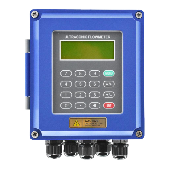
Page 14: Display And Operation
>> Ultrasonic Flow meter User Manual 6. Display and Operation 6.1 Display and keyboard Display is 2×20 characters LCD with backlight, available to set backlight time and contrast. 16-key Keyboard 9 and . are used for inputting numbers or menu numbers.
-
Page 15: Menu Details
>> Ultrasonic Flow meter User Manual 6.3 Menu Details Menu No. Function Display flow rate and NET totalizer. If the net totalizer is turned off(refer to M34), the net totalizer value shown on the screen is the value prior to its turn off. Select all totalizer unit in menu M31.
-
Page 16
>> Ultrasonic Flow meter User Manual Window for selecting the liner material, select none for pipes without any liner. Standard liner materials(no need to enter the liner sound speed) include: (0) None, No liner (1) Tar Epoxy (2) Rubber (3) Mortar (4) Polypropylene (5) Polystryol (6)Polystyrene (7) Polyester (8) Polyethylene (9) Ebonite (10) -
Page 17
>> Ultrasonic Flow meter User Manual Window for selecting the transducer mounting methods Four methods can be selected: (0) V-method (1) Z-method (2) N-method (3) W-method Display the transducer mounting spacing or distance (1) A switch for the parameters in flash memory will be loaded when power is turned on. The default option is that the parameters will be loaded. -
Page 18
>> Ultrasonic Flow meter User Manual Turn on or turn off the NEG(negative) totalizer (1) Totalizer reset (2) Restore the factory default settings parameters. Press the dot key followed by the backspace key. Attention, It is recommended to make note on the parameters before doing the restoration Manual totalizer used for easier calibration. -
Page 19
>> Ultrasonic Flow meter User Manual module, to be connected to it. Display analog inputs, AI5, current value and its corresponding temperature or pressure or liquid level value. Pulse width setup for the OCT (OCT1) output. Minimum is 6 mS, maximum is 1000 mS Select analog output (4-20mA current loop, or CL) mode. -
Page 20
>> Ultrasonic Flow meter User Manual AI5 value range. Used to enter temperature/pressure values that are corresponding to 4mA and 20mA input current. Windows to setup the frequency range (lower and upper limit) for the frequency output function. Valid range is 0Hz-9999Hz. Factory default value is 0-1000 Hz. For Version-12, Version-13, Version-14 flow meters, you need a hardware module, which shall be plugged to the Serial Expanding Bus, for the frequency output function. -
Page 21
>> Ultrasonic Flow meter User Manual OCT (Open Collect Transistor Output)/OCT1 setup By selecting a proper input source, the OCT circuit will close when the trigger event occurs. The available trigger sources are: 0. No Signal 1. Poor Signal 2. Not Ready(No*R) 3. -
Page 22
>> Ultrasonic Flow meter User Manual Window for selecting the trigger signal for the built-in batch controller. Available trig sources: 0. Key input (press ENT key to start the batch controller) 1. Serial port 2. AI3 rising edge (when AI3 receives 2mA or more current) 3. -
Page 23
>> Ultrasonic Flow meter User Manual Set the thermal energy unit: 0. GJ 1. KC 2.KWh 3. BTU Select temperature sources from T1,T2 (factory default) from AI3,AI4 Select the Specific Heat Value. Factory default is ‘GB’. Under this setting, the flow meter will calculate the enthalpy of water based on the international standard. -
Page 24
>> Ultrasonic Flow meter User Manual This is not a window but a command to print the pipe parameters. By default, the produced data will be directed to the internal serial bus (thermal printer). You can also direct those data to the serial communication port. This is not a window but a command to print the diagnostic information. -
Page 25: Quick Setup Of Measured Parameters
>> Ultrasonic Flow meter User Manual 20mA calibration for AI4 input 4mA calibration for AI5 input 20mA calibration for AI5 input Lower Temperature Zero setup for the PT100 Higher Temperature Zero setup for the PT100 Temperature Calibration at 50℃ Temperature Calibration at 84.5℃ 6.4 Quick setup of measured parameters Accurate measured parameters can have a great influence on measuring precision and reliability.
-
Page 26: Transducers Installation
>> Ultrasonic Flow meter User Manual 7. Transducers Installation 7.1 Choose installation points Proper installation point is a key for transducer installation. Following factors must be considered: Full filled pipeline, shaking, steady flow, scaling, temperature, pressure, EMI, instrument well. >> Full filled pipeline Following situations can be full filled of liquid: Vertical upward Obliquely upward…
-
Page 27
>> Ultrasonic Flow meter User Manual >> Scaling The inside scaling would have bad effect on ultrasonic signal transmission, and would decrease the inner diameter as well. As a result, the measurement accuracy can not be guaranteed. Please try to avoid choosing the installation point with inside scaling. >>Temperature The liquid temperature on installation point should be in the working range of transducers. -
Page 28: Clamp On Transducer Installation
>> Ultrasonic Flow meter User Manual 7.2 Clamp on transducer Installation △ Before installation, please verify the parameters of pipeline and liquid. To ensure the installation accuracy. 1) Installation procedure Select an installation method → Input the measuring parameters → Clean pipe surface → Install transducers →…
-
Page 29
>> Ultrasonic Flow meter User Manual 3) Positioning installation points >> V method The line between two transducers is parallel to pipe axis, and equal to the distance shown in the converter. As shown, A, B are the two installation points. >>… -
Page 30
>> Ultrasonic Flow meter User Manual 4) Clean the surface of installation points Paint, rust and anti-corrosive coating on installation points need to be cleaned. It’s good to use a polishing machine to get the metal luster. As shown below: 5) Install transducers After transducer wiring and sealing, please evenly smear 2-3mm couplant on the transducer emitting surface. -
Page 31: Insertion Type Transducer Installation
>> Ultrasonic Flow meter User Manual 7.3 Insertion type transducer installation △ Before installation, please verify the parameters of pipeline and liquid. To ensure the installation accuracy. Installation procedure Select an installation method → Input the measuring parameters → Positioning installation points →…
-
Page 32
>> Ultrasonic Flow meter User Manual >> Z method Z method can be used for all pipes > DN50mm. Make sure the vertical distance of two transducers equals to the installation distance, and the two transducers are on the same axis surface. The transmit direction mush be opposite. -
Page 33
>> Ultrasonic Flow meter User Manual 3) Positioning installation points >> V method The line between two transducers is parallel to pipe axis, and equal to the distance shown in the converter. As shown, A, B are the two installation points. >>… -
Page 34
>> Ultrasonic Flow meter User Manual 4) Fix ball valve base >> Welding Fix For carbon steel pipes, the ball valve base can be welded directly. Make sure that the central point of ball valve base is overlapped with the transducer installation point. Matters need attention: Please take the PTFE sealing gasket out from the base before welding. -
Page 35
>> Ultrasonic Flow meter User Manual 6) Install transducer and adjustment Adjust the proper insertion depth and transmit direction to get good ultrasound signal. >> Insertion depth adjustment Adjust the depth scale according to pipe wall thickness, and completely push in the transducer rod. -
Page 36: In-Line Type Transducer Installation
>> Ultrasonic Flow meter User Manual 7.4 In-line type transducer installation After choosing the installation point, install the transducer in the pipeline with companion flanges. Then connect the transducer to converter with special signal cable. Installation is complete. 1) Installation method 2) Check installation Please see details in Chapter 7.5…
-
Page 37: Check Installation
>> Ultrasonic Flow meter User Manual 7.5 Check Installation The flow meter includes the detection ability. M90 is used for checking signal strength and quality. M91 is used for checking the ratio of measured and theoretical transmission time (transmission time ratio). 1) Check signal strength and quality M90 is used for checking the signal strength and signal quality(Q value) of upstream and downstream transducers.
-
Page 38: Finish Installation
>> Ultrasonic Flow meter User Manual 8. Finish Installation 1) Commonly used menus. M00 or M02 is for meter reading. M30~M33 is for unit selection. M40 is for selecting damping factor, generally 5~10 sec. M60 is for correcting time and date. M26 is for curing parameters.
(Если вы выбираете другой преобразователь, диапазон измерения может быть DN15 ~ 6000 мм,-40C ~ 160C)
Модульный ультразвуковой расходомер может работать самостоятельно без ЖК-дисплея и модуля клавиатуры, модуль может
Использоваться отдельно в качестве расходомера. Пользователи могут даже интегрировать ряд модулей в многоканальный расходомер, который может
Измеряет до нескольких дюжин различных труб или расходомер, который имеет более высокую точность, измеряя одну и ту же трубу с
Все каналы.
Линейность: лучше 0.5%
Повторяемость: 0.20%
Точность: около 1%
Единицы измерения: Английский (США) или метрический
Типы жидкости: практически все жидкости
Дисплей: 2*10 ЖК-дисплей с подсветкой, дисплей ing instant
Связь Интерфейс: RS-485
Датчики:Модель TM-1,Или другие модели по желанию
Труба Размеры:DN50-700mm(Если вы выбираете другой преобразователь, диапазон измерения может быть DN15-6000mm)
Температура:-40C ~ 90C
Рабочая мощность: изоляция 8 ~ 36 В постоянного тока
• Сила тока: 50mA
Запись: автоматическая память положительного, отрицательного, чистого счетчика или расхода и количества тепла за последние 512 дней,
128 месяцев, 10 лет
Дальность передачи: до 1000 м
TUF 2000M ультразвуковой расходомер TM 1 Transducer (DN50 700mm) цифровой воды|flow meter|digital water flow
TUF-2000M ультразвуковой расходомер TM-1 преобразователь (DN50-700mm) цифровой расходомер воды
DN50-700mm-40C ~ 90C
(Если вы выбираете другой преобразователь, диапазон измерения может быть DN15 ~ 6000 мм,-40C ~ 160C)
Общие сведения:
Модульный ультразвуковой расходомер может работать отдельно без ЖК-дисплея и модуля клавиатуры, модуль может
Используется отдельно в качестве расходомера. Пользователи могут даже интегрировать несколько модулей в многоканальный расходомер, который может
Измеряет до нескольких десятков различных труб или расходомера, которые имеют более высокую точность, измеряя ту же трубу с
Все каналы.
Особенности:
Линейность: лучше, чем 0.5%
Повторяемость: 0.20%
Точность: около 1%
Единицы измерения: Английский (США) или метрический
Типы жидкости: практически все жидкости
Дисплей: 2*10 ЖК-дисплей с подсветкой, мгновенный дисплей
Связь Интерфейс: RS-485
Датчики:Модель TM-1,Или другие модели на выбор
Труба Размеры:DN50-700mm(Если вы выбираете другой преобразователь, диапазон измерения может быть DN15-6000mm)
Температура: -40C ~ 90C
Рабочая мощность: изоляция 8 ~ 36 В постоянного тока
• Сила тока: 50mA
Запись: Автоматическое запоминание положительного, отрицательного, чистого тотализатора или расхода и количества тепла за последние 512 дней,
128 месяцев, 10 лет
Расстояние передачи: до 1000 м
Датчики и диапазон измерения:


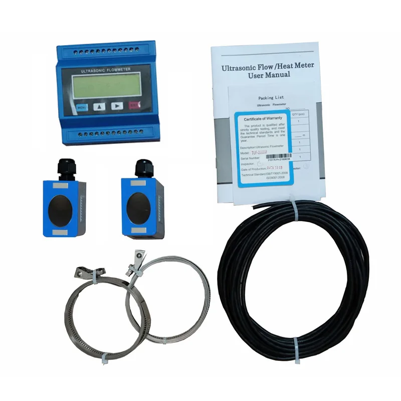
Стандартный конфигурации:
1. Основная машина… 1 шт.
2. Преобразователь (TM-1)……………….. 1 пара/каждая
3. Зажимной ремень (нержавеющая сталь) ………………………… 1 пара
4. Кабель… 5 м * 2
5. Руководство пользователя на английском языке… 1 шт.


Напоминание о кэшбэке: Что бы получить кешбек при покупке этого или другого товара на Aliexpress. Авторизуйтесь или зарегистрируйетсь в кэшбэк-сервисе, далее появиться подробная инструкция как получать кэшбэк при покупках на Алиэкспресс.

Отзывы покупателей
*о других товарах
Отзывы
Здесь вы можете оставить свой отзыв о данном товаре.
1. Вопрос: Как использовать расходомер?
О: мы можем предоставить руководство расходомера, любезно свяжитесь с нами.
2. В: Как я могу выбрать этот диаметр потока?
О: Да. Это в соответствии с вашим диаметром трубы и диапазоном потока.
3. В: Могу ли я получить образцы?
О: Да, у нас есть материалы на складе, чтобы помочь вам получить образцы так же, как мы можем.
4. Вопрос: не могли бы вы предоставить мне самое короткое время выполнения заказа?
О: у нас есть материалы на нашем складе, если вам действительно нужно, вы можете сказать нам, и мы постараемся сделать все возможное, чтобы удовлетворить вас.
5. Вопрос: Как насчет качества магнитов?
О: у нас есть Сертификация ISO,CE и ROSH, мы можем отправить вам сертификационный тест нашей компании.
6. В: Могу ли я посетить ваш завод?
О: Конечно, если вам нужно, мы поможем вам посетить наш завод.
7. В: если я заплатил, когда вы поможете мне произвести?
О: когда мы получим деньги на нашем счете, мы предоставим вам квитанцию и организуем производство
Сразу же.
Пожалуйста, свяжитесь с нами
Характеристики
TUF-2000M ультразвуковой расходомер жидкости топлива
Описание товара

TUF-2000M ультразвуковой расходомер жидкости ультразвуковой расходомер топлива
Ультразвуковой расходомер топливного масла TUF-2000M DN50-1000mm
Основные характеристики:
|
Особенности |
Описание |
|
Высокая точность |
Линейность: лучше, чем 0.5%, Повторяемость: лучше, чем 0.2%, точность: лучше, чем 1% |
|
Широкий диапазон измерений |
Несколько типов датчиков для выбора, размер трубы от dn15 мм до dn6000мм |
|
Дальнее расстояние передачи |
Соединительный Модуль и дополнительный метр через интерфейс RS-485, расстояние передачи до 1000 м |
|
Мощные функции |
Ток на выходе: 4-20мА, один канал, используется для передатчика потока/тепла; OCT выход: Два канала, используется для переключения потока/тепла; Входной ток: 4-20 мА, три канала, используется для сбора данных; Трехпроводный сигнал сопротивления (PT100): Два канала, используется для калориметра. |
|
Широкое применение |
Его уникальные особенности, особенно низкая стоимость, малый размер, высокая производительность, местный дисплей, делают его идеальным выбором для промышленной автоматизации, управления обработкой, расходомера сети, композиционирования многоканальный, высокая точность расходомера. |
Общая Спецификация:
|
Дополнительный преобразователь |
Модель |
Диапазон измерений |
Температура жидкости |
Точность |
|
|
Преобразователь с зажимом |
TS-2 (маленький размер) |
TUF-2000MNB1 |
DN32-100mm |
30 °C ~ 90 °C |
± 1% |
|
TM-1 (средний размер) Стандартная посылка |
TUF-2000MNB2 |
DN50-700mm |
|||
|
TL-1 (большой размер) |
TUF-2000MNB3 |
DN300-6000mm |
|||
|
Высокая температура Преобразователь с зажимом |
THS-1 (маленький размер) |
TUF-2000MNB4 |
DN32-100mm |
-30 °C ~ 160 °C |
|
|
THM-1 (средний размер) |
TUF-2000MNB5 |
DN50-1000mm |
|||
|
Преобразователь вставки |
TC-1 (стандарт) |
TUF-2000MNC1 |
DN80-6000mm |
-40 °C ~ 160 °C |
|
|
TLC-2 (удлиненный) |
TUF-2000MNC2 |
||||
|
Преобразователь секции Prover |
Раздел Prover |
TUF-2000MNG |
DN32-1000mm |
-40 °C ~ 160 °C |
± 0.5% |
|
Питание |
Первичный измеритель: 8-36 В постоянного тока или 10-30 В переменного тока |
||||
|
Вход |
3 4 канала-20 м аналоговый вход переменного тока, 2 канала Tri-провода сопротивления входного сигнала (PT100) |
||||
|
Выход |
Изоляция RS-485 выход, b2 канал изоляции OCT, I канал изоляции 4-20mA выход (двухпроводная система) |
||||
|
Протоколы связи |
Совместимость с протоколом MODBUS, METER-BUS, расширенным протоколом Fuji и общим протоколом счетчика воды. |


Примечание:
Аккумулятор CR2032 3V будет снят с метра авиапочтой, пожалуйста, приобретайте его в местном супермаркете.


Трекер стоимости
История цены
Отзывы покупателей