-
Contents
-
Table of Contents
-
Bookmarks
Quick Links
GE
Sensing
Druck MCX-II
Multi-Calibrator
User Manual K0320
Multi-Calibrator
Multikalibrator
Multi-calibrateur
99 Washington Street
Melrose, MA 02176
Fax 781-665-0780
TestEquipmentDepot.com
Related Manuals for GE Druck MCX-II
Summary of Contents for GE Druck MCX-II
-
Page 1
99 Washington Street Melrose, MA 02176 Fax 781-665-0780 TestEquipmentDepot.com Sensing Druck MCX-II Multi-Calibrator User Manual K0320 Multi-Calibrator Multikalibrator Multi-calibrateur… -
Page 2: Table Of Contents
Table of Contents Deutsch Introduction Inhaltsverzeichnis …….. 4 The MCX-II calibrator ……8 Pressure Measurements and Calibrations Français ………….. 8 Table des matières ……6 Automatic Calibration ……8 Digital Communicator ……10 Standard Accessories ……10 Optional Accessories ……10 Functionality Parts identification ……..
-
Page 3: User Power Supplies
To start/stop ramp cycling ….96 Millivolts ……….52 Scaled readings ……..96 Volts …………54 Milliamps/XMTR ……..54 User Power supplies Ohms …………56 Frequency ……….56 Transmitter calibration Pulse Counter Mode ……58 Setting up a calibration ……. 100 Switch position change ……
-
Page 4: Introduction
To perform automatic calibration, in the field or in the workshop, the MCX- II is supported by Intecal software. The software package and Memory Cards are optionally available from your local GE Sales Office or Distributor. K0320 Issue No. 1…
-
Page 5: Parts Identification
Functionallity Parts identification 1 POWER switch Switch to put the calibrator «ON» and «OFF». 2 CHG. (amber LED) charging indicator On when batteries are charged. The indicator should not light when non-rechargeable batteries are installed. 3 EXT. (green LED) external power indicator On when calibrator is powered from the optional line…
-
Page 6
Functionallity 15 Pt100 PROBE 4-pole mini DIN female connector for optional sensor. 16 Control and display panel Rotatable unit to position best for bench or portable use. 17 Auxilary Connectors For use with pressure module MCX-PM. [Do not make any other connections to these terminals] 18 Shoulder strap (removable) For portable use with adjustable… -
Page 7
Functionallity Screens to work with The MCX-II has four types of screen display to work with: • Menu Selection Screen Offers selection of choices. Move cursor with arrow keys to your choice. • Set up Screen Move cursor with arrow keys to fill in the blanks. -
Page 8: Keys To Work With
Functionallity Keys to work with • The EXE key Pressing this key will execute choices or output level adjustments. • The CE key Press to cancel your previous key operation or to correct a typing error. • The NUMERICAL key-pad Used to dial output levels or simulated temperatures.
-
Page 9: Power Sources
Power Sources Power from internal batteries Internal power is obtained from 6 x 1.5 V Alkaline batteries or 6 x 1.2 V Rechargeable batteries, Model R14, Baby or C size. • Installation of the batteries Switch the calibrator off before you install new batteries.
-
Page 10
Power Sources IMPORTANT: Be sure that batteries are inserted so that they are placed correctly with respect to the (+) and (-) indications in the battery compartment. If the batteries are not inserted correctly, they may leak and damage the calibrator. Do not mix old and new batteries, or batteries of different types (such as… -
Page 11: Changing From Alkaline To Rechargeable Batteries
Power Sources Changing from Alkaline to Rechargeable batteries Remove the Alkaline batteries. Remove the switch protector sticker and slide the switch to the «Ni-Cd» position. Place a new protector sticker to save the new switch position. Install 6 rechargeable batteries (purchased locally).
-
Page 12: Operating From 115 V Or 230V Line Voltage (50 Or 60 Hz)
Power Sources You may charge for periods longer than 14 hours. Note that at lower ambient temperatures the capacity of Ni-Cd batteries is significantly lower. If the batteries do not reach their normal capacity after a 14 hours charging period, cycle complete discharging and charging for at least 2 times.
-
Page 13: Set-Up
Set-up Date and Time Settings The MCX-II has been equipped with an internal clock: to indicate how many days are left before last calibration expires and to record date and time on the memory card. The clock has been factory set to Paris time at the date of calibration.
-
Page 14: Setting The Clock To Your Local Date
Set-up Setting the clock to your local date Leave the cursor at NONE at the INPUT and OUTPUT menu and press the # key to open the set-up menu. Select DATE. Press EXE again. Enter date. Press EXE to accept new date or press CE to leave the set-up menu.
-
Page 15: Temperature Readings
Set-up Temperature readings Temperature simulations and measurements can be shown in either Celsius or Fahrenheit units. Factory setting is Celsius. Readings are based on either IPTS 68 or ITS 90 temperature scales. Factory setting is ITS 90. Changing the temperature unit Leave the cursor at NONE at the INPUT and OUTPUT menu and press the # key to open the setup menu.
-
Page 16: Changing The Temperature Scale
Set-up Changing the temperature scale Leave the cursor at NONE at the INPUT and OUTPUT menu and press the # key to open the setup menu. Select TEMP.SETTING and then the temperature scale and press EXE to change. Select TEMP.SETTING and then the temperature scale and press EXE to change.
-
Page 17: Language Setting
Set-up Language Setting The MCX-II has multilingual software. The factory setting is ENGLISH. Setting the Language Leave the cursor at NONE at the measure and source menu and press # key to open the set-up menu. Select SYSTEM and then LANGUAGE and press EXE.
-
Page 18: Access Code Settings
Set-up Access code settings The ACCESS CODE is programmable by the customer. The following menus are protected by this code; ACCESS CODE Calibration menu (Electrical and pressure) 9410 is standard factory setting. Leave the cursor at NONE at the measure and source menu and press # to open the set-up menu.
-
Page 19: Lcd Screen Viewing Adjustments
Set-up LCD screen viewing adjustments Setting the backlight automatic shut off mode Leave the cursor at NONE at the INPUT and OUTPUT menu and press the # key to open the setup menu. Select system and press EXE. Next select the BACKLIGHT MODE and press EXE.
-
Page 20: Backlight On/Off Operation
Set-up Backlight on/off operation Press the LIGHT key to switch the backlight ON or OFF. Each key-pad operation will postpone shut-off for another time period. Screen contrast adjustment Turn the knob for best screen contrast. Contrast may alter with different viewing angles.
-
Page 21: Bench Or Portable Use
Set-up Bench or portable use The MCX-II calibrator can be used in the two ways as shown. Control and Display Panel can be rotated into 5 different positions for best screen viewing angle. Input and output terminals are accessible from front and back to plug-in the test leads in the most practical way.
-
Page 22: Keystroking
Set-up Keystroking Key-stroking is a solution to eliminate time consuming key-pad operations for functions you frequently use. It can store 10 different sequences of key- pad operations. Recalling a sequence will put you right back into the function as stored. You can recall a sequence from any operational situation.
-
Page 23: Clear Keystroking
Set-up Clear keystroking Leave the cursor at NONE at the measure and source menu and press the # key to open the set-up menu. Select CLEAR KEYSTROKING MEMORY and press EXE. EXE will clean the KEYSTROKE memory. Press CE to leave the set-up menu. K0320 Issue No.
-
Page 24: To Measure Signals
To measure signals General Select an input range and select DIRECT from the menu. It puts you right in the output mode. For other modes like scaled readings read the chapter » Special Output Functions». The upper part of the screen shows the window for input functions.
-
Page 25: Volts
To measure signals Volts Select VOLTS and DIRECT in the measure menu and press EXE to open the working screen. The upper window in the working screen indicates the measured Volts reading. The range is 0-60 Volts split into two (auto)ranges of 0 to 6.0000 Volts and 6.001 to 60.000 Volts.
-
Page 26: Ohms
To measure signals Ohms Select OHMS and DIRECT in the measure menu and press EXE to open the working screen. The upper window in the working screen in the indicates the measured ohms reading. The range is 0-2000 Ohms split into two (auto)ranges of 0.01 to 400.00 Ohm and 400.0 to 2000.0 Ohm.
-
Page 27: Pulse Counter Mode
To measure signals Pulse Counter Mode There are three different modes available: Counts pulses up to 999.999.999 Counts the pulses received in one minute Counter Zähler Counts the pulses received in Compteur one hour Select COUNTER in the input menu and press EXE.
-
Page 28: Switch Position Change
To measure signals Switch position change Connect the switch as indicated. Select SWITCH in the measure menu. Generate or simulate the appropriate source signal from the MCX-II to activate the switch. The measure (upper) reading tracks the source (lower) reading until the switch position changes.
-
Page 29: Circuit Continuity Tester
To measure signals Circuit continuity tester To check wiring continuity use the RTD input terminals identified with SW. If NONE has been selected in the output menu and SWITCH has been selected in the input menu, press EXE to enter the continuity check mode. Closing the test loop will activate the built-in buzzer top prove that the wiring loop has a resistance of 2200…
-
Page 30: To Measure A Thermocouple
To measure a thermocouple Go through the thermocouple input menu and make the selections as required. Press EXE to open the working screen; the measurement reading is shown in the upper window. Resolution is 0.1 degrees for most thermocouple types. Using compensation wires Thermocouples It is strongly recommended to use…
-
Page 31: Using The Standard Test Leads (Copper Wires)
• Hand-held thermometer (not supplied by GE) Read the thermometer while holding it close to the instrument terminals. Select MANUAL and open the screen to fill out the obtained reading. Press EXE to enter.
-
Page 32: To Measure A Rtd
To measure a RTD Go through the RTD input menu and make the selections as required. Press EXE to open the working screen; the measurement reading is shown in the upper window. Resolution is 0.1 or 0.01 degree depending on selected RTD type. The excitation current is 0.9 mA.
-
Page 33: Special Measurement Functions
Special Measurement Functions Scaled Readings Except in temperature measure ranges all readings can be presented in a number of 5 digits and a sign. This number could represent an engineering unit like gallons/hour, revolutions/minute or any other relationship. This facility is available on both measurement and source functions.
-
Page 34: Setting Up Scaled Readings (Flow Relationship)
Special Measurement Functions Setting up scaled readings (flow relationship) Only available on the mA ranges. Select SCALE and FLOW to open the set-up screen. High- and low-limits for the span are preset at 4 and 20 mA. Change span if necessary. Fill out both scale ends for the new scale.
-
Page 35: Output Of Electrical Signals
Output of electrical signals General Select an output range and select DIRECT from the menu. It puts you right in the output mode. For other modes read section «Special Output Functions». The lower part of the screen shows the window for output functions.
-
Page 36: Output Mode
Output of electrical signals Output mode In the OUTPUT mode you change both the output reading and the actual output at the terminals. Entering a new value through the numerical key-pad brings you back into the SET mode. Changing the output level Use the keys to ramp the output signal manually.
-
Page 37: Millivolts
Output of electrical signals Millivolts Go to millivolts in the DIRECT mode to output any signal between -10 mV and 100 mV. Adjustments are made with 1 microvolt resolution. If the adjusted output level cannot be maintained the screen will prompt the warning CHECK LOOP.
-
Page 38: Volts
Output of electrical signals Volts Go to Volts in the DIRECT mode to output any signal between zero and 12 Volts. Adjustments are made with 100 microvolts. If the adjusted output level cannot be maintained the screen will prompt the warning CHECK LOOP. Volts output Volt Geben Milliamps/XMTR…
-
Page 39: Ohms
Output of electrical signals Ohms Go through the OHM menu and select either the 0-400 or the 0-2000 Ohms range and enter the DIRECT mode. Resistance is simulated across the two terminals as shown. Connecting a third or fourth wire adapts the simulation to 3 or 4 wire input.
-
Page 40: Counter
Output of electrical signals Frequency range 0-20 kHz Go to pulse DIRECT mode to output any pulse signal between zero and 20.000 Hz. Adjustments are made with 1 Hz resolution. Frequency range 0-6000 P./Min. Same as 0-100 Hz but reads in Pulses/Minute Pulse output range 0 — 99 999 P./Hour…
-
Page 41: To Simulate A Thermocouple
To simulate a thermocouple Go through the thermocouple menu and make the selections as required. Select the DIRECT mode to simulate any temperature within the range of the chosen thermocouple type. Adjustment resolution is 0.1 degree. For cold junction compensation considerations and different wiring methods read section «To measure thermocouples»…
-
Page 42: Rtd Simulation
RTD Simulation Go through the RTD menu and make the selections as required. Select DIRECT mode to simulate any temperature within the range of the 2 wire chosen RTD type. Adjustment 2 Leiter resolution is 0.1 or 0.01 degree 2 fils depending on RTD type.
-
Page 43: Special Output Functions
Special Output Functions Step Mode In the step mode the MCX-II can generate preset output levels in three different ways; INP U T O U TP U T O H M mA/ XMT F R E Q . C O U N TE R VO L T SWITC H T/ C…
-
Page 44
Special Output Functions • Free programmable, Select PROGR Number of steps (2 to 10) and levels are free programmable. S TE P P R O G R . • 10% Divisions, Select 10% Free programmable span is automatically divided in 10 steps of 10% each. -
Page 45: Ramp Mode
Special Output Functions Ramp Mode The MCX-II can generate automatically a time linear increasing or decreasing output signal. Signal limits are free to set within any of the available output ranges. Time scales can be set between 1 and 9999 seconds. NOTE: The automatic ramp mode cannot be used together with the frequency measurement mode and…
-
Page 46: To Start/Stop A ‘One Shot’ Ramp
Special Output Functions To start/stop a ‘one shot’ ramp Press to start a one shot ramp for signal increase and press to start this ramp for signal decrease. Press simultaneously to ‘freeze’ the ramp action. To restart press . Press CE to cancel the ramping operation.
-
Page 47: User Power Supplies
User Power supplies Power supplies available for the user are designed to power transmitters, control and transducer wheatstone bridges. The following power supplies are available at the terminals as indicated: 24 VDC fixed, combined with the mA input terminals, current limited at 32 mA.
-
Page 48: Transmitter Calibration
Transmitter calibration In this function transmitter source and measure readings are both scaled in engineering units for quick comparison. Transmitter may be a linearized, non- linearized, 4-20 or 0-20 mA model for thermocouples or RTD’s. Setting up a calibration Leave the cursor on NONE in the input menu and select the required output function.
-
Page 49: To Check Or Calibrate A Transmitter
Transmitter calibration To check or calibrate a transmitter All normal key-pad functions are available to change the output. Use key to change to fixed steps. keys to step through 0%, 25%, 50%, 75% and 100% of the span as set-up. Press return to the normal key-pad functions.
-
Page 50: Temperature Transmitter Simulation
Temperature transmitter simulation User can dial a temperature in degrees to output a 4-20 mA or 0-20 mA signal. This signal can be used to simulate transmitters at control system input terminals. The simulated transmitter may be linearized or non- linearized.
-
Page 51: To Simulate A Transmitter
Temperature transmitter simulation To simulate a transmitter All normal key-pad functions are available to change the (mA) output. Use the key to move to fixed steps. keys to step through 0%, 25%, 50%, 75% and 100% of the span as set-up. Press return to the normal key-pad functions.
-
Page 52: Programmable Signal Converter
Programmable signal converter With this unique feature any input signal (including the probe) can be converted into any on the MCX-II available output signals with full galvanic isolation. Zero and span settings for both input and output are fully programmable. Setting up a signal converter Make all input and output selections as you would do when you use input…
-
Page 53: Ce Remarks
Ce Remarks Ce Remarks The MCX-II prompts EMI (Electro- Magnetic Interference) whenever the functionality is influenced by electromagnetic disturbances. The results obtained during this state are unreliable. The MCX-II is protected against failures by fast transient/burst. It restarts itself whenever this situation occurs and returns to the main screen.
-
Page 54: Service, Repair And Parts
ervice, repair and parts Recalibration of the MCX-II Leave the cursor at NONE in the INPUT and OUTPUT menu and press the # key to open the settings menu. Select CALIBRATION and press EXE. Fill out the access code and press EXE to open the calibration menu.
-
Page 55: Cold Juntion Compensation
Service, repair and parts Cold Junction Compensation Calibration To recalibrate or check the cold junction measurement system for both input and output, use an electronic thermometer with a maximum error of ±0.07°C (0.13°F). Remove the compensation wire fixation screws from the T/C terminals. Insert the thermometer probe in the appropriate T/C terminal hole and make sure a good thermal contact is made down at…
-
Page 56
Service, repair and parts NOTES: 1. Calibration standards should have a valid calibration certification and should be at least 3 times more accurate as the published accuracies for the MCX-II for each range. 2. As derived from electrical parameters, temperature sensor ranges do not require any individual recalibration. -
Page 57
Service, repair and parts Replacing the lithium battery Clock problems are in most cases caused by a weak lithium cell. To replace the cell, open the unit as described under chapter “fault finding procedures”. Use a small screwdriver to lift the cell from its socket. Remove the cell by sliding it away. -
Page 58: Fault Finding Procedures
Service, repair and parts Fault finding procedures Opening and closing the calibrator housing Remove the batteries and disconnect the unit from other equipment. Take the four T/C wire screws out and release all visible Phillips screws at the back and inside the battery compartment.
-
Page 59: Fault Finding Procedures
When the MCX-II doesn’t work properly or doesn’t work at all, it is recommended to return the unit to one of the GE Service Centres or to your local distributor after you have checked the following; Most of the problems with portable…
-
Page 60
Service, repair and parts 5. The unit doesn’t measure milliamps. Check the fuse accessible from the front. Replace fuse only by p/n 13119 or Littelfuse No. 217.400. 6. The unit doesn’t measure Ohms or RTD’s Open the MCX-II and check the fuse on the input board. -
Page 61
Kundendienst, Reparatur und Ersatzteile Maintenance, répartions et pièces détachées 5. L’appareil ne mesure pas le 5. Das Gerät mißt keine millampères Milliampere Vérifier le fusible accessible à Prüfen Sie die von der Vorderseite erreichbare l’avant. Le remplacer Sicherung. Ersetzen Sie sie uniquement par un fusible réf. -
Page 62
• Output board p/n 25103 • Digital communicator board (Optional) p/n 25107 • LCD/Key-pad processor board (in rotatable panel) p/n 25105 • Key-pad board (in rotatable panel) p/ n 25106 For GE Sales and Service Points see back cover. K0320 Issue No. 1… -
Page 63: Spare Parts List
Service, repair and parts Spare parts list Part No. Power board Assy 152 Processor board Assy 149 Input board Assy 153/II Output board Assy 154 LCD display 22500 LCD display board Assy 156/II Key-pad board Assy 157 Board spacers (3X) 25207 T/C terminal screws (2X) 25301 6x Test leads, 6x clips…
-
Page 64: Specifications
Specifications Resolution Electrical functions Range 0.001 Measure millivolts + 0…100mV 0.01 auto.ranging +100…600mV 0.001 Output millivolts -10…100mV 0.0001 Measure Volts + 0…6V 0.001 auto.ranging + 6…60V 0.0001 Output Volts 0…12V 0.001 Measure milli-ampére + 0…52mA 0.001 Output milli-ampére 0…24mA 0.001 Simulate 2-wire XMT 4…24mA 0.01…
-
Page 65
1 year accuracy Remarks 0.004% Rdg. + 0.004% f.s. +1 lsd R — input > 20MΩ 0.005% Rdg. + 0.005% f.s. +1 lsd R — input > 20MΩ 0.003% Rdg. + 0.004% f.s. +1 lsd R — output < 0.2Ω 0.009% Rdg. -
Page 66
Specifications Steps; 10 programmable, 10%, 20%, Special functions 25% div. stepping by key or adj. timer Ramp; programmable travel time for up/down and dwell Scaling; in 5 digits and sign on all electrical ranges Temp. XMT cal.; both input and output readings in temp. -
Page 67
Overrange Displays «>>>>> » Underrange Displays «<<<<< » Readings Temp. °C or °F Batteries (LR14 or C) 6x 1.5V alkaline or 1.2V NiCd Battery life Alkaline; 22 hours at 20°C (68°F) NiCd; 14 hours at 20°C (68°F) Battery life 20 mA out Alkaline;… -
Page 68: Protocol For Rs232 System Integration
Specifications Protocol for RS232 System Integration Serial port settings Bauds: 9600 Parity: none Bits: Stop: Hardware handshake: none K0320 Issue No. 1…
-
Page 69: Warranty & Liability
The equipment will be replaced, repaired or adjusted at our option. The liability of GE is restricted to that given under our warranty. No responsability is accepted for damage, loss or other expense incurred through sale or use of our equipment.
![]()
II
MCX II
MCXPortable documenting calibrator
cd
n Eliminates field calibration errors
n Reduces instrumentation maintenance costs
nOver 90 Input/Output ranges: Pressure, Temperature, Electrical and Frequency
n Interchangeable pressure modules -14.7 to 5000 psi n HART® module for Smart transmitters
n Memory card for procedure and data transfer
1
USMCX II -PDS-A132 09/00

MCX II
Portable documenting calibrator
A CALIBRATION WORKSHOP IN A
SINGLE INSTRUMENT
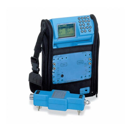
The Druck MCX II portable documenting calibrator is the most comprehensive field calibration tool available. It is the culmination of many years combined field experience with the Druck and Unomat series of portable pressure, temperature and electrical calibrators.
Designed for field use, this rugged, self-contained, battery powered package simulates and reads RTD’s, thermocouples and resistance, as well as sourcing and reading milliamps, millivolts, volts and frequency. With interchangeable single and dual sensor pressure modules over 90 input and output ranges are available.
The MCX II saves time and money with the calibration, maintenance and commissioning of instrumentation for process plants, production lines, utility processing and distribution by:
nReducing the burden imposed by quality systems such as ISO 9000.
nReducing calibration, maintenance and commissioning time.
nReducing documentation time and errors.
nReplacing several standard test instruments.
nReducing test instrument calibration costs.
nMinimising down time and maximising efficient field usage.
For example, a typical thermocouple transmitter calibration can take one hour using a mV source, look-up tables and a milliammeter. In just five minutes the MCX II can make an automatic calibration and document the results while virtually eliminating human errors.
A PCMCIA memory card provides data storage and gives total flexibility to suit different working practices. By simply exchanging PCMCIA cards, the MCX II can remain permanently in the field and when compared to serial data transfer methods this can save one to two hours a day. With a single item to calibrate the cost of re-calibration is reduced and the inconvenience of down time is minimized.
HART® communicator for SMART transmitters
The HART® communicator allows digital field adjustment of smart transmitters. Typical adjustments to sensor and analogue trims can take up to 40 minutes using conventional test equipment and a hand held communicator. With a single MCX II this time can be reduced to less than 10 minutes, including a fully documented calibration.
High precision and multi-functional
|
Typical accuracy: |
0.01% Rdg +/-0.003% FS for mA measurement |
|
0.05% Rdg for pressure measurement, |
|
|
Input: |
mA, mV, volts, T/C’s, RTD’s, pressure, ohms, |
|
frequency and switch state. |
|
|
Output: |
mA, mV, volts, T/C’s, RTD’s, ohms, and frequency. |
|
Pressure modules: |
Interchangeable single and dual ranges from -14.7 to |
|
5000 psi including gauge, absolute and differential. |
|
|
HART® communicator: |
HART® digital communicator for SMART transmitters. |
|
C/J compensation: |
Internal, external and manual. |
|
Loop Power: |
Dual 24 Vdc. |
|
Temperature probe: |
1/5 DIN accuracy P100 probe. |
|
Data storage: |
1 Mbyte PCMCIA card. |
|
Data transfer: |
PCMCIA card or RS 232 interface. |
|
PC software: |
Linkpak-W and Intecal-W. |
Easy to use
The multi-lingual user interface is an easy to use Input/Output menu with dual parameter readout. The Input and Output connectors are standard 4mm gold plated sockets which are separated and clearly labelled. The rugged impact resistant enclosure is surrounded by a durable protective carry case which allows access to all the instrument features and provides convenient pockets for storing test leads and accessories. Whether the MCX II is horizontal or vertical the rotatable display provides the optimal viewing angle. On the bench, test leads and pressure modules connect to the front face. In the field, with the MCX II held vertically by the wide neck strap, the connections are made to the rear face. With safety a major design concern, these features reduce the possibility of dropping equipment as the operators hands are kept free.
2
USMCX II -PDS-A132 09/00
Note for Owners:
Guidesimo.com webproject is not a service center of GE trademark and does not carries out works for diagnosis and repair of faulty GE Druck MCX-II equipment. For quality services, please contact an official service center of GE company. On our website you can read and download documentation for your GE Druck MCX-II device for free and familiarize yourself with the technical specifications of device.
More Measuring Instruments Devices:
-
VOLTCRAFT 12 29 00
®Multi-DMM MT-52 BEDIENUNGSANLEITUNGSeite 2 — 33Multi-DMM MT-52 OPERATING INSTRUCTIONS Page 34 — 63Multi-DMM MT-52 NOTICE D’EMPLOI Page 64 — 93Multi-DMM MT-52 GEBRUIKSAANWIJZING Pagina 94 — 123Best.-Nr. / Item-No. / N° de commande / Bestnr.: 12 29 00Version 03/11®° …
12 29 00 Multimeter, 126
-
RS PRO RS-90
AfricaRS Components SAP.O. Box 12182, Vorna Valley, 168620 Indianapolis Street,Kyalami Business Park, Kyalami, MidrandSouth Africawww.rs-components.comAsiaRS Components Ltd.Suite 1601, Level 16, Tower 1,Kowloon Commerce Centre,51 Kwai Cheong Road,Kwai Chung, Hong Kongwww.rs-components.comChinaRS Components Ltd.Suite 23 A-CEast Sea Business CentrePhase 2No. 618 Yan’an Eastern RoadShanghai, 200 …
RS-90 Measuring Instruments, 14
-
Satir CK350-VN
CK350-VN Trademark Acknowledgments • SATIR is a trademark of SATIR Ltd. • Other names and products not mentioned above may be registered trademarks or trademarks of their respective companies. Copyright © 2019 SATIR Ltd. All rights reserved. User’s manual EN Temperature Monitoring …
CK350-VN Measuring Instruments, 9
-
Extron electronics M Series
Manual M-series MA1479-1.doc Monitoring M-series Manual 19” and Wall English Manual for M-series monitoring unit with firmware ver. 102 and later. For support and information: Extron AS Tel: (+47) 63 83 33 90 Mobile: (+47) 90 03 23 94 [email protected] www.extron.no Nedre Rælingsvei 261 N-2008 FJERDINGBY …
M Series Measuring Instruments, 15
Recommended Documentation:
Download Operation & user’s manual of GE Druck MCX-II Measuring Instruments for Free or View it Online on All-Guides.com.

1

2

3

4

5

6

7

8

9

10

11

12

13

14

15

16

17

18

19

20

21

22

23

24

25

26

27

28

29

30

31

32

33

34

35

36

37

38

39

40

41

42

43

44

45

46

47

48

49

50

51

52

53

54

55

56

57

58

59

60

61

62

63

64

65

66

67

68

69

Druck MCX-II
Multi-Calibrator
User Manual K0320
GE
Sensing
Multi-Calibrator
Multikalibrator
Multi-calibrateur
99 Washington Street
Melrose, MA 02176
Fax 781-665-0780
TestEquipmentDepot.com
измерительные приборы, аналитическая аппаратура, лабораторное оборудование, расходные материалы
Снят с производства, замена — калибраторы MC4-R и MC6-R, информация предоставляется по запросу.

Назначение
- Измерение и воспроизведение параметров постоянного электрического тока (напряжение, ток);
- Измерение и воспроизведение параметров электрических цепей (сопротивление);
- Измерение и воспроизведение частоты электрических сигналов;
- Измерение и воспроизведение электрических сигналов, термосопротивлений и термопар, градуировки термометров согласно ГОСТ 6651-94 (МЭК 751), МТШ 90 ГОСТ Р50431-92, МИ 2559-99, МЭК 60548-1, МПТШ -68, МТШ-90;
- Измерение и воспроизведение количества импульсов в различных масштабах времени.
Встраиваемый в прибор HART — коммуникатор позволяет настраивать и калибровать интеллектуальные датчики, поддерживающие Hart — протокол.
Краткое описание
Многофункциональный калибратор MCX-II-R объединяет в себе калибраторы электрических сигналов, температуры и давления.
Прибор прост в использовании и удобен в обращении: входное и выходное значения отображаются на ЖК-дисплее большими четкими цифрами, там же отображается вся сопутствующая информация; прибор снабжен цифровой клавиатурой для задания величины генерируемого сигнала, программное обеспечение позволяет обрабатывать информацию: строить таблицы, графики, получать протоколы о калибровке. Информация сохраняется на PCMCIA-карте и может быть передана на компьютер для хранения и дальнейшей обработки через интерфейс RS232 или напрямую считана с карты.
Технические характеристики
Режим измерение
| Наименование | Диапазон | Разрешение | Точность | Примечание |
| Измерение мВ | ±0…100 | 0.001 | ±(0,004%ИВ+0,004%ВПИ+1мл.р.) | Вх R > 20MW |
| ±100…600 | 0.01 | ±(0,005%ИВ+0,005%ВПИ+1мл.р.) | Вх R > 20MW | |
| Измерение мA | ±0…52 | 0.001 | ±(0,010%ИВ+0,003%ВПИ+1мл.р.) | Вх R = 2.5W |
| Измерение, В | ±0…6 | 0.0001 | ±(0,009%ИВ+0,003%ВПИ+1мл.р.) | Вх R > 1MW |
| ±6…60 В | 0.001 | Вх R > 1MW | ||
| Измерение, Ом | 0…400 | 0.01 | ±(0,005%ВПИ+0,01%ИВ+1мл.р.) | Ток возбужд. 0,9мА |
| 0,4..2 кОм | 0.1 | Ток возбужд. 0,9мА | ||
| Измерение частоты | 0…655 Гц | 0.01 | ±0,01 | Вх R > 300КW |
| 655…1310 | 0.1 | ±0,1 | Вх R > 300КW | |
| 1310…10000 | 1 | ±1 | Вх R > 300КW | |
| Счетчик | 0…10e8 -1 | 1 | – | Вх R > 300КW |
| Счетчик, им. в мин | 0…6×10e5 | 1 | 1 им/мин | Вх R > 300КW |
| Счетчик, им. в мин | 0…10e7 — 1 | 1 | 1 им/мин | Вх R > 300КW |
Режим Воспроизведения
| Наименование | Диапазон | Разрешение | Точность | Примечание |
| Воспроизведение, мВ | -10…100 | 0,001 | ±(0,003%ИВ+0,004%ВПИ+1 мл.р.) | Вых R < 0,2 Ом |
| Воспроизведение, мА | 0…24 | 0,001 | ±(0,012%ВПИ+1 мл.р.) | Вх R = 900 Ом |
| Воспроизведение, В | 0…12 | 0,0001 | ±(0,004%ИВ+0,002%ВПИ+1 мл.р.) | Вх R < 0,2 Ом |
| Воспроизведение 2-х проводного ХМТ | 4…24мА | 0,001 | ±(0,025%ВПИ+1 мл.р.) | V максимум 56В |
| Воспроизведение, Ом | 0…400 | 0,01 | ±(0,005%ИВ+0,008%ВПИ+1 мл.р.) | Ток возбужд,1 мА |
| 0…2000 | 0,1 | ±(0,010%ВПИ+1 мл.р.) | Ток возбужд. 1мА | |
| Импульсы | 0…0,00000001 | 1 | — | 0…24В /34мА |
| 0…100 Гц | 0.01 | ±0.01 Гц | 0…24В /34мА | |
| 0…6000 имп/мин | 1/мин | ±1/мин | 0…24В /34мА макс. | |
| 0…10000 Гц | 1 Гц | ±1 Гц | 0…24В /34мА | |
| 0…99,999 им/час | 1/час | ±36/час | 0…24В /34мА макс. |
Измерение и воспроизведение выходных сигналов термометров сопротивления
| Термосопротивление | Диапазон, °С | Точность * | Воспроизведение, °С | |
| Разрешение, °С | Измерение, °С | |||
|
НСХ по ГОСТ 6651-94 (МЭК 751), МТШ — 90 |
||||
| Pt 1000 | -200/400 | ±0,1 | ±0,1 | 0,1 |
| Pt 500 | -200/850 | ±0,1 | ±0,1 | 0,1 |
| Pt 200 | -200/850 | ±0,2 | ±0,3 | 0,1 |
| Pt 100 | -200/850 | ±0,15 | ±0,12 | 0,03 |
| Pt 50 | -200/850 | ±0,25 | ±0,20 | 0,06 |
| 50П | -200/1100 | ±0,25 | ±0,2 | 0,06 |
| 100П | -200/934 | ±0,15 | ±0,12 | 0,03 |
| 50М | -200/200 | ±0,20 | ±0,20 | 0,1 |
| 100М | -200/200 | ±0,10 | ±0,10 | 0,1 |
| Ni100 | -60/250 | ±0,1 | ±0,1 | 0,1 |
| 100H | -60/180 | ±0,1 | ±0,1 | 0,1 |
*к каждому значению из таблицы прибавляется ±1 единица младшего разряда
Измерение и воспроизведение выходных сигналов термопар
| Тип Термопары | Характеристики в температурном эквиваленте, °С | ||
| Диапазон | Разрешение | Пределы допускаемой основной погрешности | |
|
НСХ по ГОСТ Р50431-92, МИ 2559-99, МЭК 60548-1, МПТШ -68, МТШ-90 |
|||
| ВР-1 (А-1) | 0…1700 | 0,1 | ±0,3 ±1 ед. мл. разряда |
| 1700…2500 | 0,1 | ±(0,4 ±0,00025(t-1700)) | |
| ПР (В) | 50…990 | 0,02+84,3/(t-22,6) | ±(0,11 ±430(t-12)) |
| 990…1820 | 0,1 | ±0,4 ±1 ед. мл. разряда | |
| ПП (S) | -50…127 | 0,08+12,5/(t+120) | ±(0,37 ±71,50(t+129)) |
| 127…1768 | 0,1 | ±0,5 ±1 ед. мл. разряда | |
| ХА (К) | -270…-180 | 4,8/(t+274.80) | ±24/(t+276) |
| -180…1372 | 0.1 | ±0,1 ±1 ед. мл. разряда | |
| ХК (rus) (L) | -200…800 | 0,1 | ±0,1 ±1 ед. мл. разряда |
| XK (E) | -270….-218 | 0.026+1,7/(t+272.1) | ±(0,046 ±11,3(t+274)) |
| -218…1000 | 0,1 | ±0,1 ±1 ед. мл. разряда | |
| MK (T) | -270…-160 | 0.01+4/(t+276) | ±(0,01 ±17(t+276)) |
| -160…400 | 0,1 | ±0,1 ±1 ед. мл. разряда | |
| ЖК (J) | -210…1200 | 0,1 | ±0,1 ±1 ед. мл. разряда |
| N | -270…-50 | 0.013+6,42/(t+273.2) | ±(0,08 ±34.8(t+275)) |
| -50…1300 | 0,1 | ±0,1 ±1 ед. мл. разряда | |
| R | -50…110 | 0.067+15/(t+123) | ±(0,32 ±77.4 (t+125)) |
| 110…1768 | 0,1 | ±0,5 ±1 ед. мл. разряда | |
| L (DIN) | -200…900 | 0.1 | ±0,1 ±1 ед. мл. разряда |
Примечание:
- t — значение измеряемой (воспроизводимой) температуры в °С.
- Результаты расчета разрешения и пределов допускаемой основной погрешности по приведенным формулам округлять до 1 единицы младшего разряда.
Модули давления (поставляются по доп. заказу)
| Диапазон | Погрешность | Разрешение, мбар | № заказа (избыточн.) | № заказа (абсолют.) |
| -1000…0 | ±0,1 % ВПИ | 0,02 | 612 | |
| 0…350 | ±0,1 мбар ±1 мл разряд | 0,02 | 611 | 611А |
| 0…1400 | ±0,05 % ИВ ±0,01 % ВПИ | 0,02 | 600 | 600А |
| 0…2 | ±0,05 % ИВ ±0,01 % ВПИ | 0,02 | 601 | 601А |
| 0…3,5 | ±0,05 % ИВ ±0,01 % ВПИ | 0,1 | 620 | 620А |
| 0…7 | ±0,05 % ИВ ±0,01 % ВПИ | 0,1 | 602 | 602А |
| 0…10 | ±0,05 % ИВ ±0,01 % ВПИ | 0,1 | 603 | 603А |
| 0…14 | ±0,05 % ИВ ±0,01 % ВПИ | 0,2 | 621 | 621А |
| 0…20 | ±0,05 % ИВ ±0,01 % ВПИ | 0,2 | 607 | 607А |
| 0…35 | ±0,05 % ИВ ±0,01 % ВПИ | 1 | 622 | 622А |
| 0…40 | ±0,05 % ИВ ±0,01 % ВПИ | 1 | 604 | 604А |
| 0…70 | ±0,05 % ИВ ±0,01 % ВПИ | 1 | 605 | 605А |
| 0…120 | ±0,05 % ИВ ±0,01 % ВПИ | 10 | 606 | |
| 0…135 | ±0,05 % ИВ ±0,01 % ВПИ | 10 | 623 | |
| 0…200 | ±0,05 % ИВ ±0,01 % ВПИ | 10 | 624 | |
| 0…350 | ±0,05 % ИВ ±0,01 % ВПИ | 10 | 625 |
Датчики с отрицательным диапазоном по спец. заказу. Точность уточняется при заказе.
Для молулей дифференциального давления укажите два кода, соответствующих диапазонам датчиков давления в диф. модуле из вышеприведенной таблицы.
Переходники
| № | Давление | Смачиваемые части | Макс. давление | Код |
| 1 | ¼» или 6мм пластик | Сталь 316L или витоновые | 10 бар | 615 |
| 2 | 1/8″ NPTF | Сталь 316L или витоновые | Мах 700 бар | 616 |
| 3 | Переходники для подключения удаленных или нестандартных датчиков | 617 |
Общие данные:
| Температура калибровки | 22 °С ±1 °С, влажность 45 % ±10 % | |
| Точности определены для диапазона | 17…27 °С | |
| Температурный дрейф вне диапазона | 0,0005 %/°С | |
| Условия эксплуатации | диапазон рабочих температур | -10…50 °С |
| влажность | 0…90 % без конденсации | |
| Защита | IP53 | |
| Питание | БП/ЗУ, 6×1,5В батарейки | |
| Габариты | 265×160×56 мм | |
| Вес | 2,2 кг |
Опции:
- Внешние модули давления до 8 шт. (МСХ-РМ — код датчика 1- код датчика 2* — переходник 1 — переходник 2 (*по желанию))
- Внешний образцовый термометр (Pt 100)
- Встроенный HART – коммуникатор
- PCMCIA-карта с ключом сброса
- ПО Linpak-W
php|sql engine by ivan
design by p.s.
html|php coding by fish
Почтовый адрес: 190013, Санкт-Петербург, а/я 120
Офис: Клинский проспект, д. 25
Телефон: +7 (812) 336-90-86 (многоканальный)
Транспортный отдел: +7 (931) 535-80-69
Факс: +7 (812) 336-90-86
E-mail: marketing@granat-e.ru
Общие сведения
Дата публикации — 08.05.2018
Срок свидетельства — 01.03.2004
Номер записи — 96299
ID в реестре СИ — 318699
Тип производства — серийное
Поверка
Интервал между поверками по ОТ — 1 год
Наличие периодической поверки — Да
Модификации СИ
нет данных , Калибратор многофункциональный MCX-R, Калибратор многофункциональный MCX-II-R, Калибратор многофункциональный MCX-II, MCX-R,
Производитель
Изготовитель — Фирма «Druck» / «Unomat Instruments B.V.»
Страна — НИДЕРЛАНДЫ
Населенный пункт —
Уведомление о начале осуществления предпринимательской деятельности — Да
Статистика
Кол-во поверок — 315
Выдано извещений — 6
Кол-во периодических поверок — 19
Кол-во средств измерений — 7
Кол-во владельцев — 4
Усредненный год выпуска СИ — 1999
МПИ по поверкам — 365 дн.
Наличие аналогов СИ: Калибраторы многофункциональные (MCX-R)
| ИМПОРТНОЕ СИ № в реестре, наименование СИ, обозначение, изголовитель |
ОТЕЧЕСТВЕННЫЙ АНАЛОГ № в реестре, наименование СИ, обозначение, изголовитель |
|---|
Все средства измерений Фирма «Druck» / «Unomat Instruments B.V.»
|
№ в реестре cрок св-ва |
Наименование СИ, обозначение, изголовитель | ОТ, МП | МПИ |
|---|---|---|---|
|
18086-99 01.03.2004 |
Калибраторы многофункциональные, TRX-R Фирма «Druck» / «Unomat Instruments B.V.» (НИДЕРЛАНДЫ ) |
1 год | |
|
18087-99 01.03.2004 |
Калибраторы многофункциональные, TRX-IIR Фирма «Druck» / «Unomat Instruments B.V.» (НИДЕРЛАНДЫ ) |
1 год | |
|
18088-99 01.03.2004 |
Калибраторы многофункциональные, MCX-R Фирма «Druck» / «Unomat Instruments B.V.» (НИДЕРЛАНДЫ ) |
1 год | |
|
18089-03 01.11.2008 |
Калибраторы тока, UPS-II и UPS-III Фирма «Druck» / «Unomat Instruments B.V.» (НИДЕРЛАНДЫ ) |
1 год | |
|
18089-99 01.03.2004 |
Калибраторы, UPS-II Фирма «Druck» / «Unomat Instruments B.V.» (НИДЕРЛАНДЫ ) |
1 год | |
|
21591-01 01.07.2006 |
Калибраторы многофункциональные, MCX-II-R Фирма «Druck» / «Unomat Instruments B.V.» (НИДЕРЛАНДЫ ) |
1 год |
Стоимость поверки Калибраторы многофункциональные (MCX-R)
| Организация, регион | Стоимость, руб | Средняя стоимость |
|---|---|---|
|
ФБУ Волгоградский ЦСМ Волгоградская область |
10792 | 10890 |
|
ФБУ ЦСМ Республики Башкортостан Республика Башкортостан |
4583 | 10890 |
|
ФБУ Крымский ЦСМ Республика Крым |
22819 | 10890 |
|
ФБУ ЦСМ Татарстан Республика Татарстан |
4644 | 10890 |
|
ФБУ Тест-С.-Петербург Санкт-Петербург |
24852 | 10890 |