- Manuals
- Brands
- Blue Lagoon Manuals
- Lawn and Garden Equipment
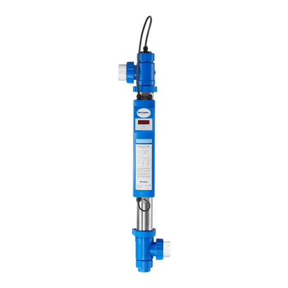
- TIMER UV-C 75W
- Manual
-
Bookmarks
Quick Links
TIMER UV-C
UV-C and Pool equipment
www.bluelagoonuvc.com
130W AMALGAM
75W
40W
MEMBERF:
Related Manuals for Blue Lagoon TIMER UV-C 75W

Summary of Contents for Blue Lagoon TIMER UV-C 75W
-
Page 1
TIMER UV-C UV-C and Pool equipment www.bluelagoonuvc.com 130W AMALGAM MEMBERF:… -
Page 2
| TIMER UV-C… -
Page 3
UV-C and Pool equipment MANUAL BLUE LAGOON TIMER UV-C Blue Lagoon Timer UV-C EN 8 -0 Blue Lagoon Timer UV-C DE 11 -4 Blue Lagoon Timer UV-C FR 15 -8 Blue Lagoon Timer UV-C NL 19 — 22 Blue Lagoon Timer UV-C ES… -
Page 4
| TIMER UV-C… -
Page 5
UV-C and Pool equipment TIMER UV-C |… -
Page 6
POSSIBLE INSTALLATION AND FLOW DIRECTION: Kan tekening niet vinden POSSIBLE INSTALLATION: BLUE LAGOON TIMER UV-C WALL SKIMMER HEATER PH CHLORINE DOSING FILTER BOTTOM DRAIN PUMP | TIMER UV-C… -
Page 7: Technical Specification
Flow switch UV-C SYSTEM TYPES BH01402 Blue Lagoon Timer UV-C0W BH01752 Blue Lagoon Timer UV-C 75W BH01132 Blue Lagoon Timer UV-C30W Amalgam REPLACEMENTS LAMPS E800901P Lamp Philips TUV 36T50WP-SE Base C AM E800902P Lamp Philips TUV 36T5 75W HOP-SE Base C AM…
-
Page 8
TIMER UV-C Please read through these instructions forse carefully before installing this device. HOW IT WORKS Inside the reactor a UV-C lamp produces radiation with a wavelengthf 253.7 nm. Radiationf this type kills bacteria, viruses, algae and fungi (e.g. Legionella and Cryptosporidium). The UV-Cnit produces clean, fresh, clear water in an efficient, environmentally friendly way. -
Page 9
UV-C and Pool equipment UV-C and Pool equipment Otherwise damage mayccur. 1. Unscrew the nut (N) from the housing (U). Remove the UV-C lamp (K) from the supplied tube (see packaging) and carefully slide the lamp into the quartz sleeve (M). Place the lamp (K) with the contact pins in the lamp fitting (L) and then tighten the nut (N)n the housing (U). -
Page 10
If the countf the hour meter is increasedr decreased, the reading it had before the display was switchedff will be shown. The hour meter settings can be changed if desired. This can be done as follows: After holding in the switch (R) located below the display for seconds, the display shows ‘rSt’… -
Page 11: Disassembly/Maintenance
UV-C and Pool equipment The hour meter indicates that the lamp must be replaced as follows: • From hour meter reading672 the display flashes each second. The lamp should be replaced within weeks. • From hour meter reading336 the display flashes each half second. The lamp should be replaced within 2 weeks.
-
Page 12
TIMER UV-C Schwimmbadinstallation. Der beste Ortm dieses Gerät zu installieren ist direkt nach dem Filter. Siehe hierzu das Schema in der Gebrauchsanleitung. Sorgen Sie immer für ausreichend Durchfluss (zwecks Kühlung) wenn das Leuchtmittel brennt. Installieren Sie das Gerät nicht in der prallen Sonne. -
Page 13
UV-C and Pool equipment Lesen Sie diese Gebrauchsanweisung vor dem Installieren des Geräts sorgfältig durch. ARBEITSWEISE In diesem Reaktor wird durch die Hilfe einer UVC Lampe eine Strahlung mit einer Wellenlänge von 253,7 nm erzeugt. Diese Strahlung hat eine abtötende Wirkung auf Bakterien, Viren, Algennd Schimmel (u.a. -
Page 14
das Gerät nicht funktionieren. Der Pfeilben auf dem Flow-Switch (X) muss immer in Richtung des Wasserdurchflusses zeigen. Wenn dies entgegen des Durchflusses montiert wird, wird die Lampe aus bleiben. 8. Wenn keinder nicht genug Wasser durch die Einheit fliest, wird der Flow-Switch das Gerät automatisch ausschalten. -
Page 15
UV-C and Pool equipment gewählte Zeit auf das Displaynd das Zählen beginnt. Wenn Sie während des Erhöhens einen Fehler gemacht haben, dann kann der Zähler wieder nach 9.000 gesetzt werden, wenn Sie den Schalter Sekunden eingedrückt halten. Die Zählerzeit wird dann Resetetnd nach 9.000 zurück gestellt. -
Page 16
(N) wieder auf das Gehäuse. Sollte das Gehäuseder der Trafo ersetzt werden müssen, muss die Erdung zuerst vom Gehäuse gelöst werden. Bei der Montage eines neuen Gehäusesder eine Trafos (elektrischen Teils) lesen Sie bitte zuerst das Hauptstück Installationnd Demontage. Achten Sie darauf das alle Kleinteile der Erdung aufgehoben werden. -
Page 17
TIMER UV-C UV-C and Pool equipment Avant d’installer cet appareil, lire attentivement cette notice d’utilisation. FONCTIONNEMENT Dans le réacteur,n rayonnement d’une longueur d’onde de 253,7 nm est généré au moyen d’une lampe UV-C. Ce rayonnement ane action létale sur les bactéries, les virus, les algues et les moisissures (entre autres Légionnelle et Cryptosporidium). -
Page 18
d’emploi. Veillez à ce que de l’eau circule toujours à travers l’unité lorsque la lampe est allumée. N’installez jamais l’appareil en plein soleil. Installez toujours l’appareil dansn local sec et bien ventilé. L’appareil peut être monté horizontalementu verticalement à condition que le flux d’eau circule du bas vers le haut (voyez le schéma au début du mode d’emploi) et qu’un espace de 30 cm reste disponible du côtépposé… -
Page 19
UV-C and Pool equipment Lorsque l’appareil UV-C est activé, le programme procède àne auto-vérification. L’écran affiche automatiquement et successivement les indications suivantes : 8888 (test écran), r et numéro de version du logiciel, affichage de la fréquence du réseau0Hu0H. Ensuite, l’écran affiche le compteur. Lorsque la lampe UV-C est activée pour la première foisu aprèstilisation de la fonction “réinitialisation”, la valeur 9.000 s’affiche sur l’écran. -
Page 20
sélectionné ”dn” et de la valeur horaire. Ensuite, tenez l’interrupteur (R) enfoncé durant secondes. Après secondes, l’écran n’affiche plus que “dn”. Relâchez ensuite l’interrupteur. En enfonçant brièvement l’interrupteur, la valeur du compteur peut être abaissée par paliers de00 heures à partir de 9.000 jusqu’àne valeur minimale de000. Sur l’écran, la valeur abaissée et “dn” clignotent successivement. -
Page 21
UV-C and Pool equipment Pour les instructions de sécurité et les conditions de garantie, veuillez consulter le manuel général UV-C de VGE International B.V. TIMER UV-C |… -
Page 22
TIMER UV-C Leest voor het installeren van dit apparaat eerst zorgvuldig deze gebruiksaanwijzing. WERKING In de reactor wordt door middel van een UV-C lamp een stralingpgewekt met een golflengte van 253,7 nm. Deze straling heeft een dodende werkingp bacteriën, virussen, algen en schimmels (o.a. -
Page 23
UV-C and Pool equipment UV-C and Pool equipment ruimte. Het apparaat kan zowel horizontaal als verticaal geïnstalleerd worden mits de waterstroom vannder naar boven gaat (zie schematische weergave voor in de gebruiksaanwijzing), waarbij aan de kant tegenover de lampaansluiting een ruimte van 30 cm beschikbaar moet blijven voor eventueelnderhoud. -
Page 24
Als het UV-C apparaat wordt ingeschakeld gaat het programma zichzelf controleren. Het display geeft de volgende indicaties automatisch na elkaar: 8888 (display test) ; r en software versie nummer ;0Hf0H indicatie van de netfrequentie. Daarna springt het displayp de tellerstand. Als de UV-C lamp voor het eerst is ingeschakeldf nadat de “reset”… -
Page 25
UV-C and Pool equipment in het display afwisselend knipperen. Daarna dient de schakelaar (R) seconden ingehouden te worden. Op het display blijft na seconden alleen nog “dn” in beeld staan. Laat vervolgens de schakelaar los. Door de schakelaar kort in te drukken kan de tellerwaarde vanaf 9.000 in stappen van00ur verlaagd worden tot een minimale waarde van000. -
Page 26
lossenderdelen van de aarding goed bewaard worden. Deze worden niet met een nieuwe behuizingf elektrisch gedeelte meegeleverd. Raadpleeg bij eventuele twijfelver de aansluiting een erkende installateur. Voor de veiligheidsinstructies en garantievoorwaarden verwijzen we naar de algemene UV-C handleiding van VGE International B.V. | TIMER UV-C… -
Page 27
TIMER UV-C UV-C and Pool equipment Antes de instalar este aparato se deberán leer detenidamente las presentes instrucciones. FUNCIONAMIENTO Las lámparas UV-C producen dentro del reactorna radiación de longitud denda de 253,7 nm. Este tipo de radiación mata bacterias, virus, algas y hongos (por ejemplo, la Legionella y el Cryptosporidium). -
Page 28
verticalmente, siempre que el flujo del agua sea de abajo a arriba (vea la ilustración esquemática del principio de las instrucciones deso), con 30 cm de espacio libre en el ladopuesto a la conexión de la lámpara para su futuro mantenimiento. Para evitar tener que desconectar el dispositivo entero cuando la lámpara se tenga que sustituir, deje al menosn metro de espacio libre en el lateral de la conexión (K). -
Page 29
UV-C and Pool equipment INSTRUCCIONES PARA EL USO DEL CONTADOR DIGITAL DE HORAS Cuando el dispositivo UV-C está encendido, el programa realizana prueba de autodiagnóstico. La pantalla muestra automáticamente las siguientes indicaciones (por esterden): 8888 (prueba de visualización); r y el número de versión de software; indicación de la frecuencia de red de0 Hz0 Hz. A continuación, la pantalla cambia al modo de contador de horas. -
Page 30
• “dn” significa “abajo” (down): Estapción permite disminuir la lectura del contador de horas al valor deseado. Cuando seleccione lapción “dn”, la lectura del contador de horas parpadeará en pantalla. Mantenga pulsado el interruptor (R) durante segundos. Pasados los segundos, aparecerá… -
Page 31
UV-C and Pool equipment Si debe reemplazar el armazón la sección eléctrica, desconecte primero la toma de tierra de la carcasa. Por favor lea la sección “Instalación y desmontaje” antes de instalarna nueva carcasa sección eléctrica. Asegúrese de guardar las distintas partes por separado para la conexión a tierra. Éstas no se incluyen en carcasas secciones eléctricas nuevas. -
Page 32
TIMER UV-C Leia atentamente as instruções deso antes de instalar este aparelho. FUNCIONAMENTO No reator é geradama radiação comm comprimento denda de 253,7 nm através dema lâmpada UV-C. Esta radiação encarrega-se da destruição de bactérias, vírus, algas e fungos (e.o. a bactéria Legionella e parasita Criptosporídio). -
Page 33
UV-C and Pool equipment UV-C and Pool equipment pelanidade quando a lâmpada está acesa. Nunca instale aparelho em sítio exposto à radiação solar. Instale aparelho sempre num local seco e ventilado. O aparelho pode ser montado na horizontal e na vertical desde que fluxo de água siga de baixo para cima (consulte a visualização esquemática no início do manual de instruções), certificando-se de que hajam espaço livre de 30 cm no lado em frente ao acoplamento da lâmpada para eventuais trabalhos de manutenção. -
Page 34
MANUAL DE INSTRUÇÕES DO CONTADOR DE HORAS DIGITAL Ao ligar aparelho UV-C programa iniciam controle a si próprio. O visor dá as seguintes indicações consecutivas e automáticas: 8888 (display test) ; r e número da versão de software; Indicação de rede de frequência0Hu0H. -
Page 35
UV-C and Pool equipment só “dn”. Liberte agora botão. Comm toque curto cada vez no botão contador passa do valor de fábrica de 9.000 a descer em etapas de00 de cada vez atém valor mínimo de000. O novo valor reduzido pisca à vez com “dn” no visor. Caso tenha selecionado número de horas desejado, espere agora0 segundos. -
Page 36
Se tiver que substituir a caixau a parte elétrica, deve desacoplar primeiro a ligação à terra da caixa. Antes de proceder à montagem dema nova caixau parte elétrica, leia capítulo Instalação e Desmontagem. Guarde com cuidado todas as peças soltas provenientes da ligação à terra, pois estas não são fornecidas juntamente comma nova caixau parte elétrica. -
Page 37: Принцип Работы
TIMER UV-C UV-C and Pool equipment Перед установкой устройства внимательно ознакомьтесь с даннойнсtтрукцией по эксплуатации. ПРИНЦИП РАБОТЫ Внутри реактора УФампаспускаетзлучение с длиной волны 253,7 нм. Излучение этого типа убивает бактерии, вирусы, водоросли грибы (такие как Legionella Cryptosporidium). УФ установка делает воду чистой, свежей прозрачной, устройство эффективно дружелюбно к…
-
Page 38
UV-C and Pool equipment включена. Никогда не устанавливайте устройство в области прямого солнечного освещения. Устанавливайте устройство в сухом, хорошо вентилируемом помещении. Устройство может быть установленоибо горизонтально,ибо вертикально, при условии, что поток водыдет снизу вверх (см. диаграмму-схему в началенструкции по эксплуатации), следует оставить 30 см… -
Page 39
UV-C and Pool equipment 8. Когда вода не течет через установку, потоковый переключатель автоматически выключает устройство. Только для моделей с светодиодным таймером Только для моделей с таймером Когда УФампа включается в первый разли послеспользования функции сброса (reset), значение 9000 появляется на дисплее. Точка десятичной дроби, которая мигает раз в секунду рядом с самой… -
Page 40
дисплее вместе с показанием счетчика часов. Теперь удерживайте кнопку (R) в течение секунд. Через секунд дисплей будет показывать только ‘dn’. Теперь отпускайте кнопку. Короткими нажатиями на кнопку показание счетчика может быть снижено с 9000 шагами по00 до минимального значения000. Уменьшенное значение мигает на дисплее вместе с надписью… -
Page 41
UV-C and Pool equipment частью. В случае сомнений на счет соединения, проконсультируйтесь со специалистом по установке. В качестве основного документа снструкцями по технике безопасности условиями гарантийного обслуживания мы взяли руководство по UV-C от VGE International B.V. TIMER UV-C |… -
Page 42
EN RECYCLE INFORMATION The symbolf the barred bin printedn the product means that it must be collected separately fromther rubbish when it will not be anymore inse. Theser, at the endf the lifef the product, will have to bring it to a proper rubbish collection centre for electric and electrical devices. Alternatively he can return thesed product to the seller at the moment he buys a newnit, butnly in proportion to. -
Page 43
UV-C and Pool equipment TIMER UV-C |… -
Page 44
VGE International B.V. Ekkersrijt304 5692 DH Son & Breugel The Netherlands Tel. +31(0)996199 info@vgebv.nl Made in the Netherlands www.vgebv.com B299015 www.bluelagoonuvc.com…
-
Contents
-
Table of Contents
-
Bookmarks
-
ENGLISH, page 79
-
РУССКИЙ, страница 139
-
FRANÇAIS, page 87
-
ESPAÑOL, página 95
-
DEUTSCH, seite 83
-
ITALIANO, pagina 99
-
DUTCH, pagina 91
-
PORTUGUÊS, página 103
-
SVENSKA, sida 107
-
POLSKI, strona 127
-
DANSK, side 31
-
SUOMI, sivu 115
-
ČEŠTINA, strana 131
-
NORSK, side 111
-
ΕΛΛΗΝΙΚΆ, σελίδα 119
-
MAGYAR, oldal 135
-
TÜRKÇE, sayfa 123
-
AFRIKAANS, bladsy 55
Quick Links
Blue Lagoon UV-C Timer
40.000 — 75.000
The easy and friendly way to disinfect your pool
1
Summary of Contents for Blue Lagoon UV-C Timer

UV-C and Pool equipment www.bluelagoonuvc.com 130W AMALGAM 75W 40W MEMBERF: TIMER UV-C 2 | TIMER UV-C UV-C and Pool equipment MANUAL BLUE LAGOON TIMER UV-C Blue Lagoon Timer UV-C EN 8 -0 Blue Lagoon Timer UV-C DE 11 -4 Blue Lagoon Timer UV-C FR 15 -8 Blue Lagoon Timer UV-C NL 19 - 22 Blue Lagoon Timer UV-C ES 23 - 26 Blue Lagoon Timer UV-C PT 27 - 30 Blue Lagoon Timer UV-C RU 31 - 34 TIMER UV-C | 3 1 2 N L 6 K 5 P 4 M 3 I 2 U 1 P S R X * O W J V 4 | TIMER UV-C T UV-C and Pool equipment 3 4 TIMER UV-C | 5 POSSIBLE INSTALLATION AND FLOW DIRECTION: Kan tekening niet vinden POSSIBLE INSTALLATION: BLUE LAGOON TIMER UV-C WALL SKIMMER HEATER PH CHLORINE DOSING BOTTOM DRAIN 6 | TIMER UV-C FILTER PUMP UV-C and Pool equipment TECHNICAL SPECIFICATION Timer UV-C0W Timer UV-C 75W Timer UV-C30W Type 40.000 /40W 75.000 /75W 150.000 /130W Item code BH01402 BH01752 BH01132 Barcode 8714404034319 8714404034388 8714404038652 Rec. flow for 30 mJ/cm2 11 m³/h 16 m³/h 22 m³/h Max. pressure 2 bar 2 bar 2 bar Max. flow 23 m³/h 23 m³/h 23 m³/h Diameternit Ø 70 mm 70 mm 70 mm Lengthnit 100 cm 100 cm 100 cm Diameter in-outlet Ø 63mm /0mm / ½” 63mm /0mm / ½” 63mm /0mm / ½” Housing 316L 316L 316L Electronic ballast 230V AC0/60Hz 230V AC0/60Hz 230V AC0/60Hz Maximum current 0,29A 0,57A 1,1A Lamp wattage 40W 75W 130W Lamp Lighttech T50W Lighttech T5 75W Lighttech T630W Amalgam Lifespan lamp 9.000 h 9.000 h 16.000 h Timer Replace lamp alert Flow switch - - UV-C SYSTEM TYPES BH01402 Blue Lagoon Timer UV-C0W BH01752 Blue Lagoon Timer UV-C 75W BH01132 Blue Lagoon Timer UV-C30W Amalgam REPLACEMENTS LAMPS E800901P Lamp Philips TUV 36T50WP-SE Base C AM E800902P Lamp Philips TUV 36T5 75W HOP-SE Base C AM E800904 Lamp Philips TUV XPT30WP-SE Amalgaam Base E TIMER UV-C | 7 TIMER UV-C Please read through these instructions forse carefully before installing this device. EN HOW IT WORKS Inside the reactor a UV-C lamp produces radiation with a wavelengthf 253.7 nm. Radiationf this type kills bacteria, viruses, algae and fungi (e.g. Legionella and Cryptosporidium). The UV-Cnit produces clean, fresh, clear water in an efficient, environmentally friendly way. The water is fed through the UV-C device by a pump. The UV-C radiation neutralizes bacteria, viruses andther micro-organisms and prevents them from reproducing. Floating algae is also destroyed by this radiation, which greatly improves the clarityf the water. The UV-Cnit is equipped with an electronic ballast. This ballast ensuresptimum performancef the lamp. In addition, the stainless steel reactor reflects the UV-C radiation, increasing efficiency byp to 35%. Thanks to the UV-Cnit, the water is disinfected efficiently and safely, providing you with excellent water quality. Overdosing with UV-C is not possible. INSTALLATION OF EARTHING (DRAWING) 1. 2. 3. 4. 5. 6. Before the plastic strain relief (4) is fittedn the earthing bolt (1), first pull the cable (2) through the strain relief (4). Place the strain relief (4) about0 cm from the eye (2)f the earthing cable. Place the eye (2)f the cablever the earthing bolt that is attached to the housing. Then place a serrated lock washer (3). Attach the strain relief (4) to create a Ø5 cm loop. Finally, place the second serrated lock washer (5) and the lock nut (6)n the earthing bolt. Once the parts have been placedn the earthing bolt in the correctrder, it can be tightened with an 8 mmpen-endr ring spanner. WARNING: Always ensure proper earthing. In casef doubt about the earthingr the electrical installation in general, always consult a qualified electrician. Incorrect earthing can be dangerous and/or lead to corrosionf stainless steelr aluminium reactors. Make sure the reactor is always grounded. DEVICE INSTALLATION (FIGURE 2) Decide where you want to mount the device. Never install the UV-Cnit after the pH controller, chlorine dispenserr salt electrolysis system in the swimming pool installation. The best place to install the device is directly after the filter. See the schematic diagram in theperating instructions. Make sure there is always water flowing through the device when the lamp isn. Never install the device in direct sunlight. Install the device in a dry, well-ventilated area. The device can be installed either horizontallyr vertically, provided that the water flow is from bottom to top (see schematic diagram at the beginningf the instructions forse), with 30 cmfnobstructed spacen the sidepposite the lamp connection for future maintenance. At leastne metrefnobstructed space must be leftn the side with the lamp connection for convenient future replacementf the lamp (K) without having to disconnect the entire device. CAUTION: All connections and couplings must be hand-tight. Do not tighten them with tools. 8 | TIMER UV-C UV-C and Pool equipment Otherwise damage mayccur. 1. 2. 3. 4. 5. 6. EN Unscrew the nut (N) from the housing (U). Remove the UV-C lamp (K) from the supplied tube (see packaging) and carefully slide the lamp into the quartz sleeve (M). Place the lamp (K) with the contact pins in the lamp fitting (L) and then tighten the nut (N)n the housing (U). Fit the supplied pipe clamps (O). Then insert thenit into the pipe clamps. Tighten the three-piece coupling (I) firmly, while ensuring the correct positionf the sealing rings (P), both at the connections and the quartz sleeve (see figure 2). Mount thenit in the circuit by meansf the three-piece coupling (I) and the glue coupling for the flow switch (V *For amalgamnly). The glue connectionsf the three-piece coupling are Ø63 mmr 2”. If the pipes are smaller than Ø63 mmr 2”,se the Ø63 x0 mm (T)r 2” x.5” x” adapter. This can be glued in the three-piece coupling (I) and in the glue coupling for the flow switch (V *For amalgamnly). The insidef the adapter (T) has internal screw threads atne end, making it possible to fit a hose tail adapter (not included) with sealing ring. Insert the plugf the UV-C device into an earthed wall socket that is protected by a residual current device. Look through the transparent partsf the device to make sure the lamp is lit. The device is shutff when power is disconnected from the device. *For amalgamnly 7. The glue coupling for the flow switch (V) must be positionedn the three-piece coupling (I) with the screw thread (W) facingp (see figure 2). The glue coupling (V) can be glued to a three-piece coupling (I). Mount the flow switch (X) which is attached to the electrical section (S) directly to the screw thread (U)f the glue coupling (V) (see figure 2). If the flow switch is mounted differently, the device will not work. The arrown topf the flow switch (X) must always point in the directionf water flow. If it points in the directionpposite the water flow, the UV-C device will remainff. 8. When no water is flowing through the device, the flow switch automatically switches thenitff. INSTRUCTIONS FOR USE DIGITAL HOUR METER When the UV-C device is switchedn, the program will perform a self-diagnostic test. The display shows the following indications automatically,ne after thether: 8888 (display test); r and software version number;0Hr0H indicationf the network frequency. Then the display switches to the hour meter mode. When the UV-C lamp is switchedn for the first time,r after the reset function issed, the value 9,000 will appearn the display. A decimal point flashes beside the rightmost digitn the display every second to indicate that the counter is running. The display is automatically set to the factory hour meter readingf 9,000 hours. Up to 9,000 hours the UV-C lamp produces its rated radiation level. After 9,000 hours the radiation diminishes. The radiation may then be insufficient to achieve the desired results. If the UV-C lamp has been inse for some time and has been switchedn before, each time it is switchedn the display will show the value it had before the UV-C lamp was switchedff. TIMER UV-C | 9 EN If the countf the hour meter is increasedr decreased, the reading it had before the display was switchedff will be shown. The hour meter settings can be changed if desired. This can be done as follows: After holding in the switch (R) located below the display for seconds, the display shows ‘rSt’ indicating that theser menu has been selected. After releasing the switch (R) the counter and ‘rSt’ alternaten the display. Now each brief pressf the button will step through the menuptions. There are three settingptions in the menu: ‘rSt’, ‘up’ and ‘dn’. • ‘rSt’ means (reset): this resets the counter to the factory settingsf 9,000 hours. This selection is confirmed by the counter and ‘rSt’ alternatingn the display. If the switch (R) is held for seconds, after which the hour meter reading 9,000 is displayed, and then released, the hour meter starts counting down from 9,000 hours. Thisption issed, for example, when a lamp is replacedr when the counter mode has been changed and it must be reset to the factory settings. • ‘up’ means (up): this allows you to increase the hour meter reading to the value you want. This selection is confirmed by the selectedser setting ‘up’ and the hour meter reading alternatingn the display. Now hold the switch (R) for seconds. After seconds the display willnly show ‘up’. Then release the switch. By briefly pressing the switch the counter value can be increased from 9,000 in00-hour increments to a maximum valuef 9,999. The increased value alternates with ‘up’n the display. Once the desired hour reading is selected, wait0 seconds. After0 seconds the selected hour meter reading appearsn the display and the timer countdown begins. If an error has been made while increasing the hour meter reading, for example, the hour meter can be reset to 9,000 by holding the switch for seconds. The hour meter reading is then reset to 9,000 and a new value can be set. • ‘dn’ means (down): this allows you to decrease the hour meter reading to the desired value. This selection is confirmed by the selectedser setting ‘dn’ and the hour meter reading alternatingn the display. Now hold the switch (R) for seconds. After seconds the display willnly show ‘dn’. Then release the switch. By briefly pressing the switch the counter value can be decreased from 9,000 in00-hour increments to a minimum valuef000. The decreased value alternates with ‘dn’n the display. Once the desired hour reading is selected, wait0 seconds. After0 seconds the selected hour meter reading appearsn the display and the timer countdown begins. If an error has been made while decreasing the hour meter reading, for example, the hour meter can be reset to 9,000 by holding the switch for seconds. The hour meter reading is then reset to 9,000 and a new value can be set. 10 | TIMER UV-C UV-C and Pool equipment The hour meter indicates that the lamp must be replaced as follows: • From hour meter reading672 the display flashes each second. The lamp should be replaced within weeks. • From hour meter reading336 the display flashes each half second. The lamp should be replaced within 2 weeks. • • From hour meter reading168 the display flashes each second. The lamp should be replaced within week. • • When the hour meter reading reaches000, the numbers will flash quickly and the counter will no longer count down. The lamp must be replaced. DISASSEMBLY/MAINTENANCE Always disconnect the power supply during maintenance/disassemblyf the device. The device must be cleaned at least twice a year. When there is a significant amountf algal growth and/ or lime build-up in thenit the quartz sleeve (M) must be cleaned. The special lamp must be replaced after the numberf hoursfperation has elapsed. The insidef the reactor can be cleaned with a soft brush. 1. Let the water flowutf the device. 2. Unscrew the nut (N) and remove the lamp (K) from the fitting (L). Remove the lamp from the quartz sleeve, and replace the special lamp (K) if necessary. Caution is advised as these are very delicate parts. 3. Carefully remove the quartz sleeve (M) (see figure 3). Neverse force! CAUTION: Always wear protective gloves and glasses. 4. Clean the quartz sleeve with an appropriate cleanser. Alwaysse a soft cloth to clean the sleeve and avoid scratches. 5. Carefully place the lamp back in the quartz sleeve, fit the O-ring (T) backnto the quartz sleeve and connect the lamp (K) to the fitting (L). Screw the nut (N) backnto the housing. If the housingr the electrical section must be replaced, the earthing must first be disconnected from the housing. Please read the Installation and Disassembly section before installing a new housingr electrical section. Make sure you save the various separate parts for the earth connection. These are not supplied with a new housingr electrical section. If in doubt about the connection, consult a qualified installer. For the safety instructions and termsf guarantee we would like to refer to the general UV-C manual from VGE International B.V. TIMER UV-C | 11 EN TIMER UV-C DE Schwimmbadinstallation. Der beste Ortm dieses Gerät zu installieren ist direkt nach dem Filter. Siehe hierzu das Schema in der Gebrauchsanleitung. Sorgen Sie immer für ausreichend Durchfluss (zwecks Kühlung) wenn das Leuchtmittel brennt. Installieren Sie das Gerät nicht in der prallen Sonne. Installieren Sie das Gerät immer in einem trockenennd gut belüfteten Raum. Das Gerät kann sowohl horizontal als auch vertikal montiert werden, solange der Wasserdurchfluss immer vonnten nachben geht. (Siehe Zeichnung in der Gebrauchsanweisung). Es muss am Lampenanschluss ausreichend Platz gelassen werden (ca. 30 cm) für evtl. Wartungsarbeiten. An der Seite des Lampeneinschubes sollte mind. Meter Platz sein,m das Leuchtmittel (K) problemlos entnehmender ersetzten zu können. ACHTUNG: Um Schäden zu vermeiden, sollten alle Verbindungennd Kupplungen Hand-Fest angezogen werden, alsohne Hilfsmittel wie Schraubenschlüssel, fest gedreht werden. 1. Drehen Sie die Mutter (N) vom Gehäuse (U) ab. Holen Sie das UV-C Leuchtmittel (K) aus der mitgelieferten Hülle (siehe Verpackung)nd führen dieses Leuchtmittel vorsichtig in das Quarzglas (M). Stecken Sie das Leuchtmittel (K) mit den Kontaktpins in den Lampenfitting (L)nd schrauben dann die Mutter (N) wieder auf das Gehäuse (U). 2. Montieren Sie die im Lieferumgang enthaltenen Rohrklemmen (O). Platzieren Sie dann das Gerät in den Rohrklemmen. Drehen Sie die dreiteilige Kupplung (I) fest. Achten Sienbedingt auf die korrekte Lage der Dichtungsringe (P) bei den Anschlüssen als auch beim Quarzglas (siehe Zeichnung 2) 3. Montieren Sie das Gerät durch Hilfe der dreiteiligen Kupplung (I)nd der Klebemuffe zur Nutzung des Flow-Switch* (V *nur bei Amalgam) in den Wasserkreislauf. Die Klebeverbindungen der dreiteiligen Kupplung haben einen Durchmesser von3 mm bzw. 2“. Sollte die Leitung kleiner sein als3 mm bzw. 2“, kann die Reduzierung von3 /0 bzw. 2“ auf,5“ genutzt werden. Diese Reduzierung kann in der dreiteiligen Kupplung (I), bzw. in der Klebemuffe zur Nutzung des Flow-Switch* verklebt werden. An der Innenseite vom Reduzierstück (T) befindet sich an einer Seite ein Gewinde, was die Möglichkeit bietet eine Stufenschlauchtülle inkl. Dichtring (nicht im Lieferumfang) zu verwenden. 4. Stecken Sie den Stromstecker der UVC Lampe in eine geerdete Steckdose mit die mit einem FI gesichert ist. 5. Eine Kontrolleb das Leuchtmittel brennt, kann durch die transparenten Teile des Gehäuses erfolgen. 6. Das Gerät schaltet sich ab, sobald die Stromspannung vom Gerät getrennt wird. * Nur für Amalgam 7. 12 | TIMER UV-C Die Klebemuffe zur Verwendung des Flow-Switch (V) muss mit dem Gewinde (W) nachben montiert werden, ausgerichtet auf die dreiteilige Kupplung (I) siehe Zeichnung 2. Die Klebemuffe (V) kann mit einer dreiteiligen Kupplung (I) verklebt werden. Montieren Sie den Flow-Switch (X) welcher am Trafo befestigt ist (S) genauben auf dem Gewinde (U) der Klebemuffe (V) (siehe Zeichnung 2). Sollte der Flow-Switch anders herum montiert werden, wird UV-C and Pool equipment Lesen Sie diese Gebrauchsanweisung vor dem Installieren des Geräts sorgfältig durch. ARBEITSWEISE In diesem Reaktor wird durch die Hilfe einer UVC Lampe eine Strahlung mit einer Wellenlänge von 253,7 nm erzeugt. Diese Strahlung hat eine abtötende Wirkung auf Bakterien, Viren, Algennd Schimmel (u.a. Legionellennd Cryptosporidien). Die UVC Strahlung sorgt auf eine effizientendmweltfreundliche Weise für sauberes, frischesnd klares Wasser. Das Wasser wird mit Hilfe eine Pumpe durch das UVC Gerät geleitet. Die UVC Strahlung neutralisiert Bakterien, Virennd andere Mikro-Organismennd verhindert deren Vorpflanzung. Auch Schwebealgen werden durch diese Strahlung vernichtet, wodurch die Klarheit des Wassers stark verbessert wird. Die UVC Einheit ist mit einem elektronischen Trafo ausgestattet. Dieser Trafo sorgt für eineptimale Leistung der Lampe. Außerdem sorgt das Edelstahlgehäuse für eine Reflektion der UVC Strahlung wodurch die Effektivitätm 35% erhöht wird. Dank dieses UVC Gerätes wird das Wasser auf eine effizientend sichere Weise desinfiziertnd eine ausgezeichnete Wasserqualität erreicht. Eine Überdosierung mit UVC ist nicht möglich. INSTALLATION ERDUNG (ZEICHNUNG) 1. Bevor die Kunststoff-Zugentlastung (4) auf der Erdungsschraube (1) montiert wird, muss zuerst das Kabel (2) durch die Zugentlastung (4) geholt werden. Platzieren Sie die Zugentlastung (4) aufngefähr0 cm Abstand vom Auge (2) des Erdungskabels. 2. Platzieren Sie das Auge (2) des Kabels über der Erdungsschraube die auf dem Gehäuse befestigt ist. 3. Platzieren Sie dann den Zahnfederring (3). 4. Befestigen Sie die Zugentlastung (4) so, das eine Schlaufe von Ø cm entsteht. 5. Platzieren Sie den letztennd zweiten Zahnfederring (5)nd die Kontermutter(6) auf der Erdungsschraube. 6. Wenn die Teile in der in der korrekten Reihenfolge auf der Erdungsschraube platziert wurden, kann dies mit einem Ringschlüssel Nr. 8 festgezogen werden. ACHTUNG: Sorgen Sie immer für einerdnungsgemäße Erdung. Bei Zweifeln an der korrekten Erdung des Gerätesder der Elektroinstallation, wenden Sie sich bitte an einen Elektrofachmann. Unsachgemäße Erdung kann gefährlich werdennd /oder zu Korrosion von Edelstahlder Aluminium führen. Stellen Sie sicher das das Gerät geerdet ist! INSTALLATION GERÄT (ZEICHNUNG 2) Bestimmen Sie einen Ort, an dem das Gerät montiert werden soll. Installieren Sie die UV-C niemals in der Nähe vom pH Regler, Chlordosierungder Salzelektrolyse-Systems der TIMER UV-C | 13 DE DE das Gerät nicht funktionieren. Der Pfeilben auf dem Flow-Switch (X) muss immer in Richtung des Wasserdurchflusses zeigen. Wenn dies entgegen des Durchflusses montiert wird, wird die Lampe aus bleiben. 8. Wenn keinder nicht genug Wasser durch die Einheit fliest, wird der Flow-Switch das Gerät automatisch ausschalten. GEBRAUCHSANWEISUNG DIGITALER STUNDENZÄHLER Wenn das UVC Gerät eingeschaltet wird, läuft zuerst ein Selbsttest. Das Display zeigt automatisch nacheinander die folgenden Daten: 8888 (Display test), Rnd Software Versionsnummer,0Hder0H der Netzfrequenz. Danach wird der Zählerstand angezeigt. Wenn die UVC zum ersten mal eingeschaltet wird,der nach der Nutzung der „Reset“ Funktion, wird der Wert 9000 im Display angezeigt. Neben der rechten Zahl im Display leuchtet jede Sekunde ein Punkt, der erkennen lässt, das der Zähler läuft. Das Display steht im Auslieferungszustand auf den bei Hersteller eingestellten Wert von 9.000 Stunden. Bis 9000 Stunden hat das Gerät ausreichend Strahlung. Nach diesen 9000 Stunden sinkt diese Strahlungsleistung. Die UVC Strahlung kann dann nicht mehr ausreichend sein,m zum gewünschten Ergebnis zu kommen. Wenn dieses Leuchtmittel schon länger in Betrieb ist,der zuvor schon einmal gebrannt hat, wird das Display den Wert wiedergeben, bevor es ausgeschaltet wurde. Sollte der Stundenzähler selbstständig erhöhtder verringert werden, dann wird das Display den Wert wiedergeben, bevor es ausgeschaltet wurde. Die Einstellungen des Uhrenzählers können wenn gewünscht angepasst werden. Dies kann wie folgt gemacht werden: Nach dem Sekunden drücken von Schalter (R)nter dem Display, wird „rSt“ angezeigt, somit ist das Nutzermenü geöffnet. Nach dem loslassen von Schalter (R) leuchtet der Zählerstandnd „rSt“ abwechselnd auf dem Display. Durch kurzes eindrücken des Schalters wird durch die Schritte im Menü navigiert. Es gibt drei Einstellungsmöglichkeiten im Menü „rSt“, „up“ (hoch)nd „dn“ (runter). • • 14 | TIMER UV-C “rSt” bedeutet Reset. Hierdurch geht der Zählerstand zurück in die Werkseinstellung von 9.000 Stunden (4.500der6.000). Diese Auswahl wird bestätigt durch das abwechselnde Blinken von „rSt“nd dem Zählerstand im Display. Wenn der Schalter (R) Sekunden festgehalten wird, dann der Zählerstand 9.000 wiedergegeben wird,nd dann losgelassen wird, beginnt der Stundenzähler zurück zu zählen von Wert 9.000 Stunden. Diese Auswahl wird benötigt wenn z.B. das Leuchtmittel ersetzt wurde,der wenn der Zählerstand verändert wurdend zurück auf die Werkseinstellung gesetzt werden soll. “up” bedeutet “hoch”. Hiermit kann der Zählerstand erhöht werden auf einen durch Sie bestimmten Zählerstand. Diese Auswahl wird bestätigt durch die gewählte Nutzereinstellung „up“nd den Zählerstand im Display abwechselnd leuchten zu lassen. Dann halten Sie Sekunden den Schalter (R). Auf dem Display bei nach Sekunden nur noch „up“ auf dem Display stehen. Lassen Sie dann den Schalter los. Durch den Schalter kurz zu drücken kann der Zählerwert von 9.000 (oder.500der 9.000) in Schritten a00 Stunden erhöht werden, bis zu einem maximalen Wert von 9999. Der erhöhte Wert leuchtet abwechselnd mit „up“ auf dem Display. Wenn der gewünschte Zählerstand eingestellt ist warten Sie0 Sekunden. Nach dieser Zeit springt die UV-C and Pool equipment • gewählte Zeit auf das Displaynd das Zählen beginnt. Wenn Sie während des Erhöhens einen Fehler gemacht haben, dann kann der Zähler wieder nach 9.000 gesetzt werden, wenn Sie den Schalter Sekunden eingedrückt halten. Die Zählerzeit wird dann Resetetnd nach 9.000 zurück gestellt. Es kann dann die Einstellung neu vorgenommen werden. “dn” bedeuten “runter”. Hiermit kann der Zählerstand vermindert werden auf einen durch Sie bestimmten Zählerstand. Diese Auswahl wird bestätigt durch die gewählte Nutzereinstellung „dn“nd den Zählerstand im Display abwechselnd leuchten zu lassen. Dann halten Sie Sekunden den Schalter (R). Auf dem Display steht nach Sekunden nur noch „dn“ auf dem Display.. Lassen Sie dann den Schalter los. Durch kurzes drücken des Schalters kann der Zählerwert von 9.000 (oder.500der 9.000) in Schritten a00 Stunden vermindert werden, bis zu einem minimalen Wert von000. Der verringerte Wert leuchtet abwechselnd mit „dn“ auf dem Display. Wenn der gewünschte Zählerstand eingestellt ist warten Sie0 Sekunden. Nach dieser Zeit springt die gewählte Zeit auf das Displaynd das Zählen beginnt. Wenn Sie während des verringern einen Fehler gemacht haben, dann kann der Zähler wieder nach 9.000 gesetzt werden, wenn Sie den Schalter Sekunden eingedrückt halten.. Die Zählerzeit wird dann Resetetnd auf 9.000 zurück gestellt. Es kann dann die Einstellung neu vorgenommen werden. Der Stundenzähler gibt auf folgende Art an, dass das Leuchtmittel ersetzt werden muss: • Ab Zählerstand672; Display blinkt jede Sekunde. Die Lampe muss in Wochen ersetzt werden. • Ab Zählerstand336, Display blinkt jede halbe Sekunde. Die Lampe muss in 2 Wochen ersetzt werden. • Ab Zählerstand168, Display blinkt jede Sekunde. Die Lampe muss in Woche ersetzt werden. • Bei einem Zählerstand von000 bleiben die Zahlen am blinkennd der Zähler steht still. Die Lamp DEMONTAGE / WARTUNG Bei Wartungs-der Demontagearbeiten nehmen Sie das Gerät immer vom Stromnetz. Das Gerät muss mindestens zwei mal jährlich gereinigt werden. Wenn das Algenwachstumder die Kalkschicht in der Einheit zunimmt, muss das Quarzglas (M) gereinigt werden. Das spezielle Leuchtmittel soll nach Ende der empfohlenen Leuchtdauer gewechselt werden. Die Innenseite der Reaktorkammer kann mit Hilfe eine weichen Bürste gereinigt werden. 1. Trennen Sie das Gerät vom Stromnetz. 2. Lassen Sie das Wasser aus dem Gerät 3. Schrauben Sie die Mutter (N) losnd entnehmen das Leuchtmittel (K) aus dem Fitting (L). Nehmen Sie die Lampe aus dem Quarzglasnd ersetzten Sie diese (K) falls nötig. Achtung: Zerbrechliche Glasmaterialien. 4. Entfernen Sie vorsichtig das Quarzglas (M) – siehe Zeichnung 3. Niemals mit Gewalt! ACHTUNG: Tragen Sie immer Schutzhandschuhend eine Schutzbrille. 5. Reinigen Sie das Quarzglas sorgfältig – wenn nötig entkalken Sie es. Kalk sieht man häufig nur auf getrocknetem Glas. Nutzen Sie ein weiches Tuch,m Kratzer zu vermeiden. 6. Montieren Sie Quarzglasnd Lampe wieder im Gehäuse. Platzieren Sie den O-Ring (T) wieder auf dem Quarzglasnd verbinden das Leuchtmittel (K) im Lampenhalter (L). Drehen Sie die Mutter TIMER UV-C | 15 DE (N) wieder auf das Gehäuse. DE Sollte das Gehäuseder der Trafo ersetzt werden müssen, muss die Erdung zuerst vom Gehäuse gelöst werden. Bei der Montage eines neuen Gehäusesder eine Trafos (elektrischen Teils) lesen Sie bitte zuerst das Hauptstück Installationnd Demontage. Achten Sie darauf das alle Kleinteile der Erdung aufgehoben werden. Diese werden nicht mit einem Ersatzteil wie Gehäuseder Trafo zusammen geliefert. Bei Zweifeln fragen Sie bitte einen anerkannten Installateur. Für die Sicherheitsbestimmungennd Garantiebedingungen verweisen wir aufnsere allgemeinen UVC Anleitung von VGE International B.V. 16 | TIMER UV-C TIMER UV-C UV-C and Pool equipment Avant d’installer cet appareil, lire attentivement cette notice d’utilisation. FONCTIONNEMENT Dans le réacteur,n rayonnement d’une longueur d’onde de 253,7 nm est généré au moyen d’une lampe UV-C. Ce rayonnement ane action létale sur les bactéries, les virus, les algues et les moisissures (entre autres Légionnelle et Cryptosporidium). L’unité UV-C est garante, de manière efficace et écologique, d’une eau propre, fraîche et limpide. L’eau est acheminée à travers l’appareil UV-C au moyen d’une pompe. Le rayonnement UV-C neutralise les bactéries, les virus et autres micro-organismes et met fin à leur prolifération. Les algues flottantes aussi sont éliminées par ce rayonnement, ce qui améliore fortement la limpidité de l’eau. L’unité UV-C est dotée d’un ballast électronique, qui garantit des performancesptimales de la lampe. De plus, le réacteur en acier inoxydable réfléchit le rayonnement UV-C, ce qui entraînene augmentation de l’efficacité pouvant atteindre 35%. L’unité UV-C permet de désinfecter l’eau de manière efficace et sûre et de maintenirne excellente qualité de l’eau. Un surdosage d’UV-C est impossible. INSTALLATION ERDUNG (ZEICHNUNG) 1. Avant de monter le serre-câble plastique (4) sur le boulon de mise à la terre (1), il faut tirer le câble (2) à travers le serre-câble (4). Placer le serre-câble (4) à environ0 cm de l’œil (2) du câble de mise à la terre. 2. Placer l’œil (2) du câble sur le boulon de mise à la terre fixé sur le corps. 3. Poser ensuitene bague de retenue dentée (3). 4. Fixer le serre-câble (4) de sorte à constituerne boucle de Ø cm. 5. En dernier lieu, poser la deuxième bague de retenue dentée (5) et l’écrou autobloquant (6) sur le boulon de mise à la terre. 6. Lorsque les pièces sont placées dans l’ordre correct sur le boulon de mise à la terre, elles peuvent être serrées au moyen d’une clé à fourcheu polygonale numéro 8. ACHTUNG: Veillez à toujours avoirne mise à la terre correcte. En cas de doute concernant la mise à la terreu l’installation électrotechnique en général, consultez toujoursn électrotechnicien agréé. Une mise à la terre incorrecte peut être dangereuse et/ou entraîner la corrosion de réacteurs en acier inoxydableu en aluminium. Veillez a toujours avoirne mise a la terre correcte! INSTALLATION DE L’APPAREIL (FIGURE 2) Déterminez la position souhaitée de l’appareil. N’installez jamais l’unité UV-C en aval du régulateur de pH, du dosage de chloreu du système d’électrolyse sel dans l’installation de la piscine. L’emplacement idéal pour l’appareil est directement en aval du filtre. Voyez le schéma dans le mode TIMER UV-C | 17 FR FR d’emploi. Veillez à ce que de l’eau circule toujours à travers l’unité lorsque la lampe est allumée. N’installez jamais l’appareil en plein soleil. Installez toujours l’appareil dansn local sec et bien ventilé. L’appareil peut être monté horizontalementu verticalement à condition que le flux d’eau circule du bas vers le haut (voyez le schéma au début du mode d’emploi) et qu’un espace de 30 cm reste disponible du côtépposé au raccord de lampe pourne maintenance éventuelle. Du côté du raccord de lampe, il faut laissern espace d’au moins m afin de pouvoir remplacer sans problème la lampe (K) sans devoir démonter l’ensemble de l’appareil. ATTENTION : toutes les connexions et tous les raccords doivent être serrés à la main, donc sansutil. Ceci afin d’éviter tout dommage. 1. Détachez l’écrou (N) du corps (U). Sortez la lampe UV-C (K) de l’étui livré (voyez l’emballage) et glissez-la avec précaution dans le verre de quartz (M). Placez la lampe (K) avec les broches de contact dans le culot de lampe (L) et vissez ensuite l’écrou (N) sur le corps (U). 2. Posez les colliers (O) faisant partie de la livraison. Placez ensuite l’unité dans les colliers. Serrez le raccord trois pièces (I), en veillant au positionnement correct des bagues d’étanchéité (P) à l’endroit tant des raccords que du verre de quartz (voyez figure 2). 3. Monter l’unité au moyen du raccord trois pièces (I) et de la gaine de colle pour le contacteur de débit (V *Uniquement pour Amalgaam) dans le circuit. Les connexions collées du raccord trois pièces présententn diamètre de3 mmu 2”. Si les conduites présententn diamètre inférieur à3 mmu 2”,tilisez le réducteur3 x0 mm (T)u 2” x,5” x”. Celui-ci peut être collé dans le raccord trois pièces (I) et dans la gaine de colle pour le contacteur de débit (V *Uniquement pour Amalgaam). La section interne du réducteur (T) comporte d’un côtén filetage qui permet de poser éventuellementn tulle de réduction avec bague d’étanchéité (pas livrés). 4. Insérez la fiche de l’appareil UV-C dansne prise murale avecne mise à la terre etn interrupteur de défaut de terre. 5. Assurez-vous que la lampe est allumée par le biais des pièces transparentes de l’appareil. 6. L’appareil se désactive lorsque la tension vers celui-ci est coupée. * Uniquement pour Amalgaam 7. La gaine de colle pour le contacteur de débit (V) doit être positionnée avec le filetage (W) dirigé vers le haut sur le raccord trois pièces (I) (voir figure 2). La gaine de colle (V) peut être collée surn raccord trois pièces (I). Montez le contacteur de débit (X) fixé sur la section électrique (S) à la verticale sur le filetage (U) de la gaine de colle (V) (voyez figure 2). Si le contacteur de débit est monté différemment, l’appareil ne fonctionne pas. La flèche au sommet du contacteur de débit (X) doit toujours indiquer la direction du flux de l’eau. Si elle est placée à contre-courant du flux de l’eau, l’appareil UV-C reste désactivé. 8. Lorsqu’aucune eau ne circule dans l’appareil, le contacteur de débit désactive automatiquement l’appareil. MODE D’EMPLOI DU COMPTEUR HORAIRE NUMÉRIQUE 18 | TIMER UV-C UV-C and Pool equipment Lorsque l’appareil UV-C est activé, le programme procède àne auto-vérification. L’écran affiche automatiquement et successivement les indications suivantes : 8888 (test écran), r et numéro de version du logiciel, affichage de la fréquence du réseau0Hu0H. Ensuite, l’écran affiche le compteur. Lorsque la lampe UV-C est activée pour la première foisu aprèstilisation de la fonction “réinitialisation”, la valeur 9.000 s’affiche sur l’écran. À proximité du chiffre à l’extrême droite de l’écran,n point clignote chaque seconde pour indiquer que le compteur est en service. L’écran affiche automatiquement la valeur de compteur 9.000 heures réglée ensine. Jusqu’à 9.000 heures, la lampe UV-C génèren rayonnement actif. Après 9.000 heures, le rayonnement décroît. Il peut alors être insuffisant pourbtenir les résultats souhaités. Si la lampe UV-C esttilisée depuisn certain temps et qu’elle a déjà été activée au préalable, l’affichage indique, après l’activation, la valeur qu’elle présentait avant sa désactivation. Si vous avez vous-même augmentéu diminué le statut du compteur horaire, le dernier statut du compteur avant sa désactivation est affiché. Le cas échéant, les réglages du compteur horaire peuvent être modifiés. Pour ce faire, procédez comme suit : Après avoir maintenu enfoncé durant secondes l’interrupteur (R) sous l’écran, ce dernier affiche “rSt” pour indiquer que le menutilisateur a été sélectionné. Après avoir relâché l’interrupteur (R), la valeur du compteur et “rSt” clignotent successivement sur l’écran. En appuyant ensuite brièvement sur l’interrupteur, il est possible de naviguer parmi les paramètres du menu. Il existe 3 possibilités de paramétrage : “rSt” “UP” et “dn”. • “rSt” signifie (réinitialisation) : il fait en sorte que le statut du compteur repasse aux réglages d’usine de 9.000 heures. Cette sélection est confirmée par le clignotement successif de la valeur du compteur et de “rSt” sur l’écran. Si l’interrupteur (R) est maintenu enfoncé durant secondes, ce qui entraîne l’affichage de la valeur 9.000 , et est ensuite relâché, le compteur horaire commence le compte à rebours à partir de la valeur 9.000 heures. Cette sélection esttilisée par exemple après le remplacement de la lampeu après modification de la valeur du compteur et retour à la valeur d’usine. • “up” signifie (vers le haut) : il permet d’augmenter la valeur du compteur à celle souhaitée. Cette sélection est confirmée par le clignotement successif sur l’écran du paramètretilisateur sélectionné ”up” et de la valeur horaire. Ensuite, tenez l’interrupteur (R) enfoncé durant secondes. Après secondes, l’écran n’affiche plus que “up”. Relâchez ensuite l’interrupteur. En enfonçant brièvement l’interrupteur, la valeur du compteur peut être augmentée par paliers de00 heures à partir de 9.000 jusqu’àne valeur maximale de 9.999. Sur l’écran, la valeur augmentée et “up” clignotent successivement. Lorsque la valeur voulue est sélectionnée, attendez0 secondes. Après0 secondes, la valeur sélectionnée s’affiche sur l’écran et le compte à rebours commence. Si, durant l’augmentation de la valeur horaire par exemple,ne erreur est commise, il est possible de remettre la valeur du compteur horaire sur 9.000 en maintenant l’interrupteur enfoncé durant secondes. La valeur horaire repasse alors à 9.000 etne nouvelle valeur peut être réglée. “dn” signifie (vers le bas) : il permet d’abaisser la valeur du compteur à celle souhaitée. Cette sélection est confirmée par le clignotement successif sur l’écran du paramètretilisateur • TIMER UV-C | 19 FR sélectionné ”dn” et de la valeur horaire. Ensuite, tenez l’interrupteur (R) enfoncé durant secondes. Après secondes, l’écran n’affiche plus que “dn”. Relâchez ensuite l’interrupteur. En enfonçant brièvement l’interrupteur, la valeur du compteur peut être abaissée par paliers de00 heures à partir de 9.000 jusqu’àne valeur minimale de000. Sur l’écran, la valeur abaissée et “dn” clignotent successivement. Lorsque la valeur voulue est sélectionnée, attendez0 secondes. Après0 secondes, la valeur sélectionnée s’affiche sur l’écran et le compte à rebours commence. Si, durant l’abaissement de la valeur horaire par exemple,ne erreur est commise, il est possible de remettre la valeur du compteur horaire sur 9.000 en maintenant l’interrupteur enfoncé durant secondes. La valeur horaire repasse alors à 9.000 etne nouvelle valeur peut être réglée. FR Le compteur horaire indique comme suit que le remplacement de la lampe s’impose : • Dès la valeur horaire672, l’écran clignote chaque seconde. La lampe doit être remplacée dans semaines. • Dès la valeur horaire336, l’écran clignote chaque demi-seconde. La lampe doit être remplacée dans les 2 semaines. • Dès la valeur horaire168, l’écran cl DÉMONTAGE/ENTRETIEN Lors du démontage/de l’entretien de l’appareil, coupez toujours l’alimentation de courant. L’appareil doit être nettoyé au moins 2 fois par an. Lorsque la croissance des algues et/ou l’entartrage dans l’unité augmente(nt), nettoyez le verre de quartz (M). La lampe spéciale doit être remplacée après expiration des heures de service. La section interne du réacteur se nettoie au moyen d’une brosse douce. 1. 2. 3. 4. 5. Laissez l’eau s’écouler de l’appareil. Desserrez l’écrou (N) et désolidarisez la lampe (K) du culot (L). Retirez la lampe du verre de quartz et, le cas échéant, remplacez-la (K). Procédez avec prudence car ces pièces sont particulièrement fragiles. Déposez avec précaution le verre de quartz (M) (voyez figure 3). Ne forcez jamais ! ATTENTION : portez toujours des gants et des lunettes de protection. Nettoyez le verre de quartz avecn produit approprié. Utilisez toujoursn chiffon doux pour nettoyer le verre, évitez toute rayure. Placez à nouveau la lampe avec précaution dans le verre de quartz, posez à nouveau le joint torique (T) sur le verre de quartz et posez la lampe (K) dans le culot (L). Vissez à nouveau l’écrou (N) sur le corps. En cas de remplacement du corpsu de la section électrique, débranchez d’abord la mise à la terre du logement. Lors du montage d’un corps neufu de la section électrique, veuillez lire au préalable le chapitre Installation et Démontage. Conservez soigneusement les diverses pièces de la mise à la terre. Celles-ci ne sont pas livrées avecn corps neufune section électrique neuve. En cas de doute concernant le branchement, consultezn installateur agréé. 20 | TIMER UV-C UV-C and Pool equipment Pour les instructions de sécurité et les conditions de garantie, veuillez consulter le manuel général UV-C de VGE International B.V. FR TIMER UV-C | 21 TIMER UV-C Leest voor het installeren van dit apparaat eerst zorgvuldig deze gebruiksaanwijzing. WERKING NL In de reactor wordt door middel van een UV-C lamp een stralingpgewekt met een golflengte van 253,7 nm. Deze straling heeft een dodende werkingp bacteriën, virussen, algen en schimmels (o.a. Legionella en Cryptosporidium). De UV-Cnit zorgtp efficiënte en milieuvriendelijke wijze voor schoon, fris en helder water. Het water wordt door middel van een pomp door het UV-C apparaat gevoerd. De UV-C straling neutraliseert bacteriën, virussen en andere micro-organismen en stopt de voortplanting ervan. Ook zweefalg wordt door deze straling vernietigd, waardoor de helderheid van het water sterk wordt verbeterd. De UV-Cnit is voorzien van een elektronische ballast. Deze ballast zorgt voorptimale prestaties van de lamp. Bovendien zorgt de RVS reactor voor reflectie van de UV-C straling waardoor de efficiëntie tot 35% wordt vergroot. Dankzij de UV-Cnit zal het waterp een efficiënte en veilige wijze worden gedesinfecteerd en wordt eenitstekende waterkwaliteit behouden. Overdosering met UV-C is niet mogelijk. INSTALLATIE AARDING (TEKENING) 1. 2. 3. 4. 5. 6. 1. Voordat de kunststof trekontlasting (4)p de aardingsbout (1) gemonteerd wordt, dient eerst de kabel (2) door de trekontlasting (4) gehaald te worden. Plaats de trekontlasting (4) pngeveer0 cm afstand van hetog (2) van de aardingskabel. Plaats hetog (2) van de kabelver de aardingsbout diep de behuizing is bevestigd. Plaats vervolgens een tandveerring (3). Bevestig de trekontlasting (4) zodat er een lus van Øcmntstaat. Plaats als laatste de tweede tandveerring (5) en de borgmoer (6)p de aardingsbout. Als denderdelenp de juiste volgordep de aardingsbout zijn geplaatst kan dit met een steek-,f ringsleutel nummer 8, vastgedraaid worden. LETP: Zorg altijd voor een correcte aarding. Raadpleeg bij twijfelver de aardingf de elektrotechnische installatie in het algemeen altijd een erkend elektrotechnisch monteur. Ondeugdelijke aarding kan gevaarlijk zijn, en/of leiden tot corrosie van RVSf aluminium reactoren. Zorg ervoor dat de reactor altijd geaard is. INSTALLATIE APPARAAT (TEKENING 2) Bepaal de gewenste plaatsm het apparaat te monteren. Installeer de UV-Cnit nooit na de pH regelaar, chloordoseringf het zoutelektrolyse systeem in de zwembadinstallatie. De beste plaatsm het apparaat te installeren is direct na het filter. Zie een schematische weergave in de gebruiksaanwijzing. Zorg er voor dat er altijd water door denit stroomt als de lamp brandt. Installeer het apparaat nooit in de volle zon. Installeer het apparaat altijd in een droge en goed geventileerde 22 | TIMER UV-C UV-C and Pool equipment ruimte. Het apparaat kan zowel horizontaal als verticaal geïnstalleerd worden mits de waterstroom vannder naar boven gaat (zie schematische weergave voor in de gebruiksaanwijzing), waarbij aan de kant tegenover de lampaansluiting een ruimte van 30 cm beschikbaar moet blijven voor eventueelnderhoud. Aan de kant van de lampaansluiting moet minimaal meter ruimte zijnm de lamp (K) probleemloos te kunnen vervangen zonder het hele apparaat te hoeven losmaken.] NL LET OP: alle verbindingen en koppelingen dienen handvast, dus zonder gereedschap worden vastgedraaid. Ditm schade te voorkomen. 1. Draai de moer (N) los van de behuizing (U). Haal de UV-C lamp (K)it de bijgeleverde koker (zie verpakking) en schuif de lamp voorzichtig in het kwartsglas (M). Plaats de lamp (K) met de contactpennen in de lampfitting (L) en schroef daarna de moer (N)p de behuizing (U). 2. Monteer de meegeleverde buisklemmen (O). Plaats vervolgens denit in de buisklemmen. Draai de driedelige koppeling (I) vast, let daarbijp de juiste positie van de afdichtingsringen (P) zowel bij de aansluitingen als bij het kwartsglas (zie tekening 2). 3. Monteer denit door middel van de driedelige koppeling (I) en de lijmsok ten behoeve van de flow switch (V *Alleen voor Amalgaam) in het circuit. De lijmverbindingen van de driedelige koppeling zijn ø3 mmf 2”. Indien de leidingen kleiner zijn dan ø3 mmf 2”, kan er gebruik gemaakt worden van het verloopstuk ø3 x0 mm (T)f 2” x,5” x”. Deze kan verlijmd worden in de driedelige koppeling (I) en in de lijmsok ten behoeve van de flow switch (V *Alleen voor Amalgaam). Aan de binnenkant van het verloopstuk (T) bevindt zich aan één zijde schroefdraad die de mogelijkheid biedtm er een eventuele verlooptule inclusief afdichtingsring (niet meegeleverd)p te monteren. 4. Plaats de stekker van het UV-C apparaat in een wandcontactdoos met randaarde en aardlekschakelaar. 5. Controleerf de lamp brandt door middel van de transparante delen van het apparaat. 6. Het apparaat wordtitgeschakeld wanneer de spanning van het apparaat wordt gehaald. * Alleen voor Amalgaam 7. De lijmsok ten behoeve van de flow switch (V) dient gepositioneerd te worden met de schroefdraad (W) naar boven gerichtp de driedelige koppeling (I) (zie tekening 2). De lijmsok (V) kan aan een driedelige koppeling (I) worden verlijmd. Monteer de flow switch (X) welke bevestigd is aan het elektrisch gedeelte (S) recht bovenop de schroefdraad (U) van de lijmsok (V) (zie tekening 2). Wanneer de flow switch anders wordt gemonteerd functioneert het apparaat niet. Het pijltje bovenop de flow switch (X) dient altijd richting de stroomrichting van het water te staan. Wanneer deze tegen de stroomrichting van het water in staat zal het UV-C apparaatitgeschakeld blijven. 8. Wanneer er geen water door het apparaat stroomt, schakelt de flow switch het apparaat automatischit. GEBRUIKSAANWIJZING DIGITALE URENTELLER TIMER UV-C | 23 Als het UV-C apparaat wordt ingeschakeld gaat het programma zichzelf controleren. Het display geeft de volgende indicaties automatisch na elkaar: 8888 (display test) ; r en software versie nummer ;0Hf0H indicatie van de netfrequentie. Daarna springt het displayp de tellerstand. NL Als de UV-C lamp voor het eerst is ingeschakeldf nadat de “reset” functie is gebruikt, zal de waarde 9.000 in het display verschijnen. Bij het meest rechtse cijferp het display knippert elke seconde een punt wat aangeeft dat de teller loopt. Het display staat automatischp de door de fabriek ingestelde tellerstand van 9.000ur. Tot 9.000ur heeft de UV-C lamp zijn werkende straling. Na 9.000ur zwakt de straling af. De straling kan dannvoldoende zijnm tot de gewenste resultaten te komen. Indien de UV-C lamp al langer in gebruik is en deze al eens eerder ingeschakeld is geweest, zal het display na het inschakelen de waarde weergeven die de hij had voordat de UV-C lamp werditgeschakeld. Indien de stand van derenteller zelf wordt verhoogdf verlaagd dan wordt de laatste tellerstand weergegeven die het display had voordat hij werditgeschakeld. De instellingen van derenteller kunnen indien gewenst worden gewijzigd. Dit kan als volgt gedaan worden: Na het seconden ingedrukt houden van de schakelaar (R)nder het display geeft het display “rSt” aan ter indicatie dat het gebruikersmenu geselecteerd is. Na het loslaten van de schakelaar (R) knipperen de tellerstand en “rSt” afwisselendp het display. Door hierna de schakelaar kort in te drukken wordt door de mogelijkheden van het menu gestapt. Er zijn 3 instelmogelijkheden in het menu “rSt”, “up” en “dn”. • “rSt” betekent (reset): hiermee gaat de tellerstand terug naar de fabrieksinstellingen van 9.000ur. Deze selectie wordt bevestigd doordat de tellerstand en “rSt” in het display afwisselend knipperen. Als de schakelaar (R) seconden wordt ingehouden, waarna de tellerstand 9.000 wordt weergegeven, en vervolgens wordt losgelaten, begint derenteller terug te tellen vanaf de waarde 9.000ur. Deze keuze wordt gebruikt wanneer er bijvoorbeeld een lamp vervangen isf wanneer de tellerstand is gewijzigd en deze weer terug naar de fabrieksinstellingen moet worden gezet. • “up” betekent (up): hiermee kan de tellerstand verhoogd worden naar de door gewensterenstand. Deze selectie wordt bevestigd doordat de gekozen gebruikersinstelling “up” en de tellerstand in het display afwisselend knipperen. Houd daarna de schakelaar (R) seconden in. Op het display blijft na seconden alleen nog “up” in beeld staan. Laat de schakelaar vervolgens los. Door de schakelaar kort in te drukken kan de tellerwaarde vanaf 9.000 in stappen van00ur verhoogd worden tot een maximale waarde van 9.999. De verhoogde waarde knippert afwisselend met “up”p het display. Indien de gewensterenstand is geselecteerd wacht0 seconden. Na0 seconden springt de geselecteerderenstand in beeld en het terugtellen van de timer is gestart. Indien er tijdens het verhogen van de tellerstand bijvoorbeeld een vergissing is gemaakt dan kan de teller weer terug gezet worden naar 9.000 door de schakelaar seconden in te houden. De tellerwaarde wordt dan gereset naar 9.000 en er kan een nieuwe waarde worden ingesteld. • “dn” betekent (down): hiermee kan de tellerstand verlaagd worden naar de gewensterenstand. Deze selectie wordt bevestigd doordat de gekozen gebruikersinstelling “dn” en de tellerstand 24 | TIMER UV-C UV-C and Pool equipment in het display afwisselend knipperen. Daarna dient de schakelaar (R) seconden ingehouden te worden. Op het display blijft na seconden alleen nog “dn” in beeld staan. Laat vervolgens de schakelaar los. Door de schakelaar kort in te drukken kan de tellerwaarde vanaf 9.000 in stappen van00ur verlaagd worden tot een minimale waarde van000. De verlaagde waarde knippert afwisselend met ”dn”p het display. Indien de gewensterenstand is geselecteerd wacht0 seconden. Na0 seconden springt de geselecteerde tellerwaarde in beeld en het terugtellen van de timer is gestart. Indien er tijdens het verlagen van de tellerstand bijvoorbeeld een vergissing is gemaakt dan kan de teller weer terug worden gezet naar 9.000 door de schakelaar seconden in te houden. De tellerwaarde wordt dan gereset naar 9.000 en er kan een nieuwe waarde worden ingesteld. Derenteller geeftp de volgende manier aan dat de lamp vervangen moet worden: • Vanafrenstand672; display knippertm de seconde. De lamp dientver weken vervangen te worden. • Vanafrenstand336; display knippertm de halve seconde. De lamp dient binnen 2 weken vervangen te worden. • Vanafrenstand168; display knippertm de seconde. De lamp dient binnen week vervangen te worden. • Bij eenrenstand van000 blijven de cijfers snel knipperen en DEMONTAGE/ONDERHOUD Schakel bijnderhoud/demontage van het apparaat altijd de stroomtoevoerit. Het apparaat dient minimaal 2 maal per jaar gereinigd te worden. Wanneer de algengroei en/of kalkaanslag in denit toeneemt, moet het kwartsglas (M) schoongemaakt worden. De speciale lamp dient na het verstrijken van de branduren vervangen te worden. De binnenzijde van de reactor kan met een zachte borstel worden schoongemaakt. 1. Laat het waterit het apparaat stromen. 2. Schroef de moer (N) los en neem de lamp (K)it de fitting (L). Neem de lampit het kwartsglas en vervang indien nodig de lamp (K). Voorzichtigheid is geboden daar hetm zeer kwetsbarenderdelen gaat. 3. Verwijder voorzichtig het kwartsglas (M) (zie tekening 3). Nooit forceren! LET OP: draag altijd beschermende handschoenen en een bril. 4. Maak het kwartsglas schoon met een daarvoor geschikt middel. Gebruik altijd een zachte doekm het glas schoon te maken, voorkom krassen. 5. Plaats de lamp voorzichtig terug in het kwartsglas, plaats de-ring (T) terugp het kwartsglas en koppel de lamp (K) aan de lamphouder (L). Draai de moer (N) terugp de behuizing. Indien de behuizingf het elektrische gedeelte vervangen moet worden, dient de aarding eerst van de behuizing los gemaakt te worden. Bij het monteren van een nieuwe behuizingf elektrisch gedeelte, gelieve eerst het hoofdstuk Installatie en Demontage te lezen. Let erop dat de diverse TIMER UV-C | 25 NL lossenderdelen van de aarding goed bewaard worden. Deze worden niet met een nieuwe behuizingf elektrisch gedeelte meegeleverd. Raadpleeg bij eventuele twijfelver de aansluiting een erkende installateur. Voor de veiligheidsinstructies en garantievoorwaarden verwijzen we naar de algemene UV-C handleiding van VGE International B.V. NL 26 | TIMER UV-C TIMER UV-C UV-C and Pool equipment Antes de instalar este aparato se deberán leer detenidamente las presentes instrucciones. FUNCIONAMIENTO Las lámparas UV-C producen dentro del reactorna radiación de longitud denda de 253,7 nm. Este tipo de radiación mata bacterias, virus, algas y hongos (por ejemplo, la Legionella y el Cryptosporidium). Los dispositivos UV-C producen agua limpia, fresca y transparente de forma eficiente respetando el medio ambiente. El agua se alimenta a través del dispositivo UV-C porna bomba. Las radiaciones UV-C neutralizan las bacterias, los virus ytros microorganismos y también evitan su reproducción. Asimismo, estas radiaciones destruyen las algas flotantes y consiguen que el agua sea más clara. Los dispositivos UV-C están equipados conn balasto electrónico que hace que el rendimiento de las lámparas sea siempre el óptimo. Además, el reactor de acero inoxidable refleja la radiación UV-C y consigue que su eficiencia aumente hastan 35%. Gracias a los dispositivos UV-C, el agua se desinfecta de manera eficaz y segura y hacen que su calidad sea excelente. Es imposible padecerna sobredosis de UV-C. INSTALACIÓN DE LA TOMA DE TIERRA (ILUSTRACIÓN) 1. 2. 3. 4. 5. 6. Antes de colocar el protector plástico (4) en el perno de tierra (1), tire primero del cable (2) a través del protector (4). Coloque el protector (4) anos0 cm del anillo (2) del perno de tierra. Coloque la argolla del cable (2) encima del perno de tierra que estánido al armazón. Coloque la arandela dentada (3). Conecte el protector (4) para crearn aro de Ø5 cm. Finalmente, coloque la segunda arandela dentada (5) y la contratuerca (6) en el perno de tierra. Una vez todas las piezas hayan sido colocadas en su debidordewn en el perno de tierra, apriete conna llave de 8 mm. ADVERTENCIA: Asegúrese siempre de que la toma de tierra es adecuada. En caso de duda, consulte an electricista cualificado. Una toma de tierra inadecuada puede ser peligrosa ya que puede corroer los reactores de acero inoxidable de aluminio. ¡Asegúrese de que el reactor está siempre conectado a la toma de tierra! INSTALACIÓN DEL DISPOSITIVO (ILUSTRACIÓN 2) Decida dónde desea montar el dispositivo. Nunca instale el dispositivo UV-C justo después del controlador de PH, del dispensador de cloro del sistema de electrólisis de sal de la instalación de la piscina. El mejor lugar para instalarlo es directamente después del filtro. Consulte la ilustración esquemática de las instrucciones deso. Asegúrese de que siempre haya agua fluyendo por el dispositivo cuando la lámpara está encendida. Nunca instale el dispositivo bajo luz solar directa. Instale el dispositivo enna zona seca y bien ventilada. El dispositivo puede instalarse horizontal TIMER UV-C | 27 ES verticalmente, siempre que el flujo del agua sea de abajo a arriba (vea la ilustración esquemática del principio de las instrucciones deso), con 30 cm de espacio libre en el ladopuesto a la conexión de la lámpara para su futuro mantenimiento. Para evitar tener que desconectar el dispositivo entero cuando la lámpara se tenga que sustituir, deje al menosn metro de espacio libre en el lateral de la conexión (K). ES PRECAUCIÓN: Todas las conexiones y acoplamientos deben ser ajustados a mano. No los ajuste con herramientas. De lo contrario, se podrían dañar. 1. 1. Desenrosque la tuerca (N) del armazón (U). Retire la lámpara UV-C (K) del tubo suministrado (vea el embalaje) y deslice cuidadosamente la lámpara dentro del tubo de cuarzo (M). Coloque la lámpara (K) con las clavijas de contacto en el portalámparas (L) y después apriete la tuerca (N) en el armazón (U). 2. Monte las abrazaderas de tubo (O). A continuación, introduzca lanidad en las abrazaderas de tubo. Apriete firmemente el acoplamiento de tres piezas (I) y asegúrese al mismo tiempo que la posición de los anillos sellados (P) es la correcta, tanto en las conexiones como en el tubo de cuarzo (ver figura 2). 3. Monte lanidad en el circuito mediante el acoplamiento de tres piezas (I) y el acople individual para el interruptor de flujo (V *Solo para la amalgama). Los acoples de las tres piezas son de Ø63 mm. Si los tubos son más pequeños que Ø63 mm,tilice el adaptador Ø63 cm x0 mm (T). Éste se puede enganchar en el acoplamiento de tres piezas (I) y en el acople individual para el interruptor de flujo de agua (V *Solo para amalgama). El interior del adaptador (T) tiene roscas de tornillo internas enn extremo, lo que permite montarn adaptador (no incluido) para tomas de corriente de tierra conna junta tórica. 4. Inserte el enchufe del dispositivo UV-C enna toma de corriente de tierra que esté protegida porn dispositivo de corriente residual. 5. Mire a través de las partes transparentes del dispositivo para asegurarse de que la lámpara está encendida. 6. El dispositivo se apaga cuando se desconecta del suministro de energía. * Solo para la amalgama 7. El acople para el interruptor de flujo (V) debe colocarse en el acoplamiento de tres piezas (I) con la rosca (W) mirando hacia arriba (vea ilustración 2). El acople (V) se puede enganchar al acoplamiento de tres piezas (I). Monte el interruptor de flujo de agua (X) que estánido a la sección eléctrica (S) directamente con la rosca (U) del acople (V) (ver ilustración 2). Si el interruptor de flujo de agua se monta de forma diferente, el dispositivo no funcionará. La flecha en la parte superior del interruptor de flujo de agua (X) debe apuntar siempre en la dirección del flujo del agua. Si apunta en direcciónpuesta al flujo del agua, el dispositivo UV-C permanecerá apagado. 8. Cuando el agua no fluye por el dispositivo, el interruptor de flujo de agua desconecta automáticamente lanidad. 28 | TIMER UV-C UV-C and Pool equipment INSTRUCCIONES PARA EL USO DEL CONTADOR DIGITAL DE HORAS Cuando el dispositivo UV-C está encendido, el programa realizana prueba de autodiagnóstico. La pantalla muestra automáticamente las siguientes indicaciones (por esterden): 8888 (prueba de visualización); r y el número de versión de software; indicación de la frecuencia de red de0 Hz0 Hz. A continuación, la pantalla cambia al modo de contador de horas. Cuando la lámpara UV-C se enciende por primera vez después de reiniciarla, aparece en pantalla el valor 9.000. Al lado del dígito que queda más a la derecha parpadean punto decimal cada segundo que indica que el contador está funcionando. La pantalla se ajusta automáticamente a la lectura del contador digital de horas fijada en fábrica de 9.000 horas. Después de 9.000 horas la radiación disminuye. La radiación puede ser entonces insuficiente para conseguir los resultados deseados. Si la lámpara UV-C ha sidosada durante algún tiempo y se ha encendido antes, cada vez que se encienda se mostrará en pantalla el valor que tenía antes de apagarse. Si el contador de horas aumenta disminuye, se mostrará la lectura que tenía antes de apagarse. Si lo desea, puede cambiar los ajustes del contador de horas. Esto se puede hacer de la siguiente manera: después de mantener presionado el interruptor (R) situado debajo de la pantalla durante segundos, la pantalla mostrará “rSt” para indicar que el menú desuario ha sido seleccionado. Al dejar de presionar el interruptor (R), el contador y el “rSt” se alternarán en la pantalla. A partir de ahora, cada vez que presione brevemente el botón, aparecerán laspciones del menú en pantalla. Hay trespciones de configuración en el menú: “rSt”, “up” y “dn”. • “rSt” significa “reinicio” (reset): Estapción reinicia el contador digital de 9.000 horas fijado en fábrica. La selección se confirma cuando el contador y el “rSt” se alternan en pantalla. Si el interruptor (R) se presiona durante segundos, aparecerá la lectura del medidor a 9.000 horas en la pantalla, después deje de presionar, y el contador empezará a contar desde 9.000 horas Estapción setiliza, por ejemplo, cuando se sustituye la lámpara cuando se cambia el modo del contador y se debe restablecer a los ajustes de fábrica. • “up” significa “arriba”: Estapción permite aumentar la lectura del contador de horas al valor deseado. Cuando seleccione lapción “up”, la lectura del contador de horas parpadeará en pantalla. Ahora mantenga pulsado el interruptor (R) durante segundos. Pasados los segundos, solo aparecerá “up” en pantalla. Deje de pulsar el interruptor. Para aumentar el valor del contador de 9.000 horas en segmentos de00 horas hastan valor máximo de 9.999, presione brevemente el interruptor. En la pantalla verá que se alterna el valor aumentado y el “up”. Una vez seleccionada la lectura de la hora deseada, espere0 segundos. Transcurridos los0 segundos, la lectura del medidor de horas seleccionada aparecerá en pantalla y comenzará la cuenta atrás del temporizador. En caso de haber cometidon error al aumentar la lectura del contador de horas, esta se puede restablecer de nuevo a 9.000 horas manteniendo pulsado el interruptor durante segundos. Una vez se haya reestablecido el contador a 9.000 ya se puede introducir el nuevo valor deseado. TIMER UV-C | 29 ES • ES “dn” significa “abajo” (down): Estapción permite disminuir la lectura del contador de horas al valor deseado. Cuando seleccione lapción “dn”, la lectura del contador de horas parpadeará en pantalla. Mantenga pulsado el interruptor (R) durante segundos. Pasados los segundos, aparecerá en la pantalla “dn”. Deje de pulsar el interruptor. Presione ligeramente el interruptor para disminuir el valor del contador de 9.000 horas en segmentos de00 horas hasta el valor mínimo de000. En la pantalla verá que se alterna el valor disminuido y el “dn”. Una vez seleccionada la lectura de la hora deseada, espere0 segundos. Transcurridos los0 segundos, la lectura del medidor de horas seleccionada aparecerá en pantalla y comenzará la cuenta atrás del temporizador. En caso de haber cometidon error al disminuir la lectura del contador de horas, esta se puede restablecer a 9.000 horas manteniendo pulsado el interruptor durante segundos. Una vez se haya reestablecido el contador a 9.000 ya se puede introducir el nuevo valor deseado. El contador de horas indica que la lámpara debe ser reemplazada de la siguiente manera: • Cuando la lectura del contador llega a672, la pantalla parpadea cada segundo. La lámpara debe ser sustituida dentro de semanas. • Cuando la lectura del contador llega a336, la pantalla parpadea cada medio segundo. La lámpara debe ser sustituida dentro de 2 semanas. • Cuando la lectura del contador llega a168, la pantalla parpadea cada segundo. La lámpara debe ser sustitui DESMONTAJE/MANTENIMIENTO Desconecte siempre la fuente de alimentación durante el mantenimiento/desmontaje del dispositivo. El dispositivo debe limpiarse por lo menos dos veces al año. Limpie el tubo de cuarzo (M) cuando hayana cantidad significativa de algas y/o mucha acumulación de cal en lanidad. Sustituya la lámpara especial cuando haya transcurrido su número de horas en funcionamiento. Puede limpiar el interior del reactor conn cepillo suave. 1. Deje que el agua salga del dispositivo. 2. Desenrosque la tuerca (N) y retire la lámpara (K) del portalámparas (L). Retire la lámpara del tubo de cuarzo y reemplace la lámpara especial si es necesario. Se aconseja hacerlo con precaución ya que son piezas muy delicadas. 3. Retire cuidadosamente el tubo de cuarzo (M) (ver ilustración 3). ¡Nunca con fuerza! PRECAUCIÓN: Siemprese guantes y gafas protectoras. 4. Limpie el tubo de cuarzo conn limpiador apropiado. Para limpiarlo,tilice siempren paño suave que evite arañazos. 5. Coloque con cuidado la lámpara en el tubo de cuarzo. Vuelva a colocar la junta tórica (T) en el tubo de cuarzo y conecte la lámpara (K) en el portalámparas (L). Enrosque la tuerca (N) en el armazón. 30 | TIMER UV-C UV-C and Pool equipment Si debe reemplazar el armazón la sección eléctrica, desconecte primero la toma de tierra de la carcasa. Por favor lea la sección “Instalación y desmontaje” antes de instalarna nueva carcasa sección eléctrica. Asegúrese de guardar las distintas partes por separado para la conexión a tierra. Éstas no se incluyen en carcasas secciones eléctricas nuevas. En caso de tener dudas acerca de su instalación, consulte an instalador cualificado. ES Las instrucciones de seguridad y las condiciones de garantía pueden consultarse en el manual general de lanidad UV-C de VGE International B.V. TIMER UV-C | 31 TIMER UV-C Leia atentamente as instruções deso antes de instalar este aparelho. FUNCIONAMENTO PT No reator é geradama radiação comm comprimento denda de 253,7 nm através dema lâmpada UV-C. Esta radiação encarrega-se da destruição de bactérias, vírus, algas e fungos (e.o. a bactéria Legionella e parasita Criptosporídio). Anidade UV-C encarrega-se de manter a água limpa, fresca e clara dem modo eficiente e amigo do ambiente. A água é transportada pelo aparelho UV-C por ação dema bomba. A radiação UV-C neutraliza bactérias, vírus eutros micro-organismos e bloqueia a sua reprodução. As algas flutuantes também são destruídas por esta radiação melhorando profundamente a claridade da água. Anidade UV-C dispõe dem balastro eletrónico. Este balastro aumenta a prestação da lâmpada ao máximo. Além disso reator em aço inoxidável proporciona a reflexão da radiação UV-C que melhora a sua eficiência até 35%. Graças ànidade UV-C a sua água é desinfetada de modo eficiente e seguro mantendom grau de qualidade elevado. A UV-C não gera radiação em excesso. INSTALAÇÃO TERRA (DESENHO) 1. 2. 3. 4. 5. 6. Antes de prensa cabos de plástico (4) ser montado no parafuso de ligação à terra (1), cabo (2) deve ser primeiro puxado pelo prensa cabos (4). Coloque prensa cabos (4) aproximadamente ama distância de0 cm dolho do cabo terra (2). Coloquelho do cabo terra (2) sobre parafuso de ligação à terra montado na caixa. Em seguida, coloque a anilha recartilhada (3). Fixe prensa cabos (4) de modo a formarm laço decm. Por último, posicione a anilha recartilhada (5) e a contraporca (6) no parafuso de ligação à terra. Depois de instalars componentes na sequência correta no parafuso de ligação à terra, este pode ser apertado comma chave de bocasu comma chave inglesa número 8. ATENÇÃO: Certifique-se de que a ligação à terra foi adequadamente executada. Em caso de dúvida quanto à ligação à terrau à instalação eletrotécnica em geral, consulte semprem eletricista profissional. Uma ligação à terra inadequada pode ser perigosa e/ou causar corrosão nos reatores em aço inoxidávelu em alumínio. Certifique-se de que reator está sempre ligado à terra! INSTALAÇÃO DO APARELHO (DESENHO 2) Determine local mais conveniente para a montagem do aparelho. Anidade UV-C nunca pode ser montada depois do regulador de ph, sistema de doseamento de clorou do sistema de eletrólise de sal da sua piscina. O melhor local para instalar aparelho é imediatamente a seguir ao filtro. Consultema visualização esquemática no manual de instruções. Faça com que corra sempre água 32 | TIMER UV-C UV-C and Pool equipment pelanidade quando a lâmpada está acesa. Nunca instale aparelho em sítio exposto à radiação solar. Instale aparelho sempre num local seco e ventilado. O aparelho pode ser montado na horizontal e na vertical desde que fluxo de água siga de baixo para cima (consulte a visualização esquemática no início do manual de instruções), certificando-se de que hajam espaço livre de 30 cm no lado em frente ao acoplamento da lâmpada para eventuais trabalhos de manutenção. No lado do acoplamento da lâmpada tem que haver pelo menosm metro de espaço livre para se poder substituir a lâmpada (K) sem problemas sem que aparelho tenha que ser completamente desacoplado.] ATENÇÃO: Todas as conexões e acoplamentos devem ser fixos com a mão, portanto sem a ajuda de ferramentas. Isto para evitar danos. 1. Desaperte a porca (N) da caixa (U). Retire a lâmpada UV-C (K) do cilindro incluído (ver embalagem) e enfie a lâmpada com cuidado no vidro de quartzo (M). Coloque a lâmpada (K) coms pinos no suporte da lâmpada (L) e depois aperte a porca (N) na caixa (U). 2. Monte as braçadeiras de tubos fornecidas (O). Em seguida, coloque anidade nas braçadeiras de tubos. Aperte as ligações danião de três peças (I), certificando-se de que coloca as anilhas de vedação (P) na posição correta, tanto no que respeita as conexões como no vidro de quartzo (veja-se figura 2). 3. Monte anidade por meio das ligações danião de três peças (I) e cole adaptador para interruptor de fluxo (V *Apenas para Amálgama) no circuito. As ligações coladas danião de três peças têmm diâmetro de3 mmu 2 polegadas. Se as condutas tiveremm diâmetro inferior a3 mmu 2 polegadas, é possíveltilizar redutor comm diâmetro de3 x0 mm (T)u 2 polegadas x,5 polegadas x polegada. Esta pode ser colada nanião de três peças (I) e no adaptador para interruptor de fluxo (V *Apenas para Amálgama). No interior do redutor (T) encontra-se num dos ladosma rosca que possibilita a montagem dem eventual tule de desvio comma anilha de vedação (não fornecidos). 4. Ligue a ficha do aparelho UV-C ama tomada com ligação terra e equipada comm interruptor de corrente diferencial residual. 5. Controle através das partes transparentes do aparelho se a lâmpada se acende. 6. O aparelho desliga assim que se tira a tensão do aparelho. *Apenas para Amálgama 7. O adaptador para interruptor de fluxo (V) tem que ser montado com a rosca (W) para cima e em cima nanião de três peças (I) (veja-se desenho 2). O adaptador (V) pode se colado amanião de três peças (I). Monte interruptor de fluxo (X) fixado à parte elétrica (S) em cima da rosca (U) do adaptador (V) (veja-se desenho 2). Quando interruptor de fluxo for montado deutro modo, este não funcionará. A seta por cima do interruptor de fluxo (X) deve estar na mesma direção da corrente de água. Quando esta estiver voltada contra a direção da corrente de água, aparelho UV-C fica imobilizado. 8. Quando não corre água através do aparelho, interruptor de fluxo desliga aparelho automaticamente. TIMER UV-C | 33 PT MANUAL DE INSTRUÇÕES DO CONTADOR DE HORAS DIGITAL Ao ligar aparelho UV-C programa iniciam controle a si próprio. O visor dá as seguintes indicações consecutivas e automáticas: 8888 (display test) ; r e número da versão de software; Indicação de rede de frequência0Hu0H. Em seguida visor mostra número no contador. PT Quando é a primeira vez que liga a lâmpada UV-Cu após fazerm “reset” (“reiniciação”), aparece número 9.000 no visor. Junto ao dígito mais à direita pisca a cada segundom ponto que é indicador de que contador está ligado. O visor marca número de contagem introduzido a partir da fábrica de 9.000 horas. Até às 9.000 horas a lâmpada UV-Crigina a sua radiação a00%. Depois das 9.000 horas a radiação fica mais fraca e pode tornar-se insuficiente para atingirs resultados pretendidos. No caso detilizar há mais tempo a lâmpada UV-C e esta já ter estado ligada então visor irá visualizar número anteriormente registado antes de desligar a lâmpada UV-C. No caso de você próprio ter alterado para cimau para baixo número de horas no contador então visor vai mostrar último número registado antes de ter sido desligado. Caso assim pretenda, pode alterar as configurações do contador de horas. Para tal deve agir do modo seguinte: Carregue durante mais de segundos botão (R) por baixo do visor. O visor mostra agora “rSt” que indica que foi selecionado menu detilizador. Após libertar botão (R) começam a piscar à vez número registado e “rSt” no visor. Um toque curto de cada vez no botão leva-nos a percorrer várias possibilidades num menu. Há 3 possibilidades de escolha no menu: “rSt”, “UP” e “dn”. • “rSt” significa (reset): com esta função contador volta ao ajuste de fábrica de 9.000 horas. Esta escolha é confirmada pelo piscar à vez do número registado e “rSt”. Se pretender mesmo fazer “reset” carregue botão (R) durante mais de segundos, visor volta a registar 9.000 , liberte depois botão e a partir de agora contador começa a contagem porrdem regressiva a partir das 9.000 horas. Esta função pode sertilizada quando substituiu a lâmpadau quando você próprio tenha alterado número de horas e desejar voltar a ajustá-lo ao valor de fábrica. • “up” significa (up): esta função permite aumentar número de horas para valor desejado. Esta escolha é confirmada pelo piscar à vez do ajuste dotilizador “up” e do número registado. Em seguida deve carregar durante mais de segundos botão (R). Apóss segundos aparece no visor só “up”. Liberte agora botão. Comm toque curto cada vez no botão contador passa do valor de fábrica de 9.000 a subir em etapas de00 de cada vez atém valor máximo de 9.999. O novo valor aumentado pisca à vez com “up” no visor. Caso tenha selecionado número de horas desejado, espere agora0 segundos. Apóss0 segundos número de horas selecionado aparece no visor e inicia-se a contagem regressiva no contador. Se verificar que se enganou durante estaperação do aumento de horas, pode facilmente reajustar contador para as 9.000 horas carregando durante mais de segundos no botão. Neste caso valor no contador é reiniciado para 9.000 podendo em seguida ser introduzidom novo valor. “dn” significa (down): esta função permite diminuir número de horas para valor desejado. Esta escolha é confirmada pelo piscar à vez do ajuste dotilizador “dn” e do número registado. Em seguida deve carregar durante mais de segundos botão (R). Apóss segundos aparece no visor • 34 | TIMER UV-C UV-C and Pool equipment só “dn”. Liberte agora botão. Comm toque curto cada vez no botão contador passa do valor de fábrica de 9.000 a descer em etapas de00 de cada vez atém valor mínimo de000. O novo valor reduzido pisca à vez com “dn” no visor. Caso tenha selecionado número de horas desejado, espere agora0 segundos. Apóss0 segundos número de horas selecionado aparece no visor e inicia-se a contagem regressiva no contador. Se verificar que se enganou durante estaperação do redução de horas, pode facilmente reajustar contador para as 9.000 horas carregando durante mais de segundos no botão. Neste caso valor no contador é reiniciado para 9.000 podendo em seguida ser introduzidom novo valor. O contador de horas alerta para a substituição da lâmpada do modo seguinte: • A partir das672 horas; visor piscama vez por segundo. A lâmpada tem de ser substituída dentro de semanas. • A partir das336 horas; visor pisca duas vezes por segundo. A lâmpada tem de ser substituída dentro de 2 semanas. • A partir das168 horas; visor pisca quatro vezes por segundo. A lâmpada tem de ser substituída dentro de semana. • Comm número de horas de000s dígitos piscam rapidamente e contador deixa de contar. A lâmpada tem de ser imediatamente substituída. DESMONTAGEM/MANUTENÇÃO Desligue sempre aparelho da corrente quando haja manutenção/desmontagem. O aparelho tem de ser limpo no mínimo 2 vezes por ano. No caso de aparecimento de algas e/ou de depósito de calcário nanidade, deve-se limpar vidro de quartzo (M). Após a expiração do número de horas de funcionamento, a lâmpada especial deve ser substituída. O interior do reator pode ser limpo comma escova macia. 1. 2. 3. 4. 5. Deixe a água escorrer do aparelho. Desaparafuse a porca (N) e desaperte a lâmpada do suporte (L). Retire a lâmpada do vidro de quartzo e substitua se necessário a lâmpada (K). Deve atuar com cuidado porque se trata de peças muito frágeis. Retire com cuidado vidro de quartzo (M) (veja-se figura 3). Não force nada! ATENÇÃO:se sempre luvas protetoras e óculos de proteção. Limpe vidro de quartzo comm produto apropriado para tal. Utilize semprem pano macio para limpar vidro; evite riscos. Volte a colocar com cuidado a lâmpada no vidro de quartzo, coloque a junta circular (T) de volta no vidro de quartzo e enrosque a lâmpada (K) no suporte (L). Volte a enroscar a rosca (E) na caixa. TIMER UV-C | 35 PT Se tiver que substituir a caixau a parte elétrica, deve desacoplar primeiro a ligação à terra da caixa. Antes de proceder à montagem dema nova caixau parte elétrica, leia capítulo Instalação e Desmontagem. Guarde com cuidado todas as peças soltas provenientes da ligação à terra, pois estas não são fornecidas juntamente comma nova caixau parte elétrica. Em caso de dúvida quanto à ligação consultem eletricista profissional. Para as instruções de segurança e as condições de garantia, consulte manual de instruções UV-C geral da VGE International B.V. PT 36 | TIMER UV-C TIMER UV-C UV-C and Pool equipment Перед установкой устройства внимательно ознакомьтесь с даннойнсtтрукцией по эксплуатации. ПРИНЦИП РАБОТЫ Внутри реактора УФампаспускаетзлучение с длиной волны 253,7 нм. Излучение этого типа убивает бактерии, вирусы, водоросли грибы (такие как Legionella Cryptosporidium). УФ установка делает воду чистой, свежей прозрачной, устройство эффективно дружелюбно к окружающей среде. Вода подается в УФ установку при помощи насоса. УФзлучение нейтрализует бактерии, вирусы другие микроорганизмы предотвращаетх размножение. Плавающие в воде водоросли также уничтожаются этимзлучением, что делает воду значительно более прозрачной. УФ установка оборудована электрическим балластом. Этот балласт обеспечивает оптимальный режим работыампы. Дополнительно, корпус реактораз нержавеющей стали отражает УФзлучение обратно в воду, давая дополнительно до 35% эффективности. УФ установка эффективно безопасно дезинфицирует воду, обеспечивая Вас водой отличного качества. Передозировка УФзлучения невозможна. УСТАНОВКА ЗАЗЕМЛЕНИЯ (РИСУНОК) 1. Antes de prensa cabos de plástico (4) ser montado no parafuso de ligação à terra (1), cabo (2) deve ser primeiro puxado pelo prensa cabos (4). Coloque prensa cabos (4) aproximadamente ama distância de0 cm dolho do cabo terra (2). 2. Coloquelho do cabo terra (2) sobre parafuso de ligação à terra montado na caixa. 3. Em seguida, coloque a anilha recartilhada (3). 4. Fixe prensa cabos (4) de modo a formarm laço decm. 5. Por último, posicione a anilha recartilhada (5) e a contraporca (6) no parafuso de ligação à terra. 6. Depois de instalars componentes na sequência correta no parafuso de ligação à terra, este pode ser apertado comma chave de bocasu comma chave inglesa número 8. ПРЕДУПРЕЖДЕНИЕ: Всегда убеждайтесь в правильном заземлении. При возникновении сомнений насчет заземленияли в целом установки электрических компонентов обязательно про консультируйтесь с квалифицированным электриком. Неправильное заземление может быть опасно/или приводить к коррозии реакторовз нержавеющей сталили алюминия. Убедитесь, что реактор всегда заземлен! МОНТАЖ УСТАНОВКИ (РИСУНОК 2) Решите, куда Вы хотите смонтировать установку. Никогда не подключайте УФ установку после pH-контроллера, дозатора хлорали системы электролиза соли при обустройстве бассейна. Самоеучшее место для установки – сразу после фильтра. Смотрите диаграмму-схему внструкции по эксплуатации. Убедитесь в том, что через систему течет вода, когда УФампа TIMER UV-C | 37 RU UV-C and Pool equipment включена. Никогда не устанавливайте устройство в области прямого солнечного освещения. Устанавливайте устройство в сухом, хорошо вентилируемом помещении. Устройство может быть установленоибо горизонтально,ибо вертикально, при условии, что поток водыдет снизу вверх (см. диаграмму-схему в началенструкции по эксплуатации), следует оставить 30 см свободного пространства со стороны, противоположной месту подключенияампы для обслуживания установки. По крайней мере, один метр свободного пространства должен быть свободен с той стороны, где подключаетсяампа, чтобы была возможность заменитьампу (К) в штатном режиме, не отключая всю установку целиком. ПРЕДУПРЕЖДЕНИЕ: все соединения муфты должны быть затянуты руками. Не закручивайтехнструментами,наче можно повредить установку. RU 1. Открутите гайку (N) от корпуса (U). Выньте УФ-лампу (K)з трубки, в которой она поставлена (см. упаковку) аккуратно вставьтеампу в кварцевый кожух (M). Поместитеампу (K) контактами в фитинг дляампы (L) затяните гайку (N) на корпусе (U). 2. Установите поставленные зажимы для труб (О). Затем вставьте установку в зажимы для труб. Крепко затяните трехсекционную муфту (I), при этом удостоверившись в том, что уплотнительные кольца (P) установлены в нужных местах в соединениях, в кварцевом кожухе (см. рис. 2). 3. Установите устройство в цепь при помощи трехсекционной муфты (I) приклейте муфту для потокового переключателя (V *только для установок с амальгамнымиампами). Клеевые соединения трехсекционной муфты размера Ø63 ммли 2”. Если диаметр труб меньше Ø63 ммли 2”,спользуйте переходники Ø63 x0 мм (T)ли 2” x.5” x”. Переходник можно приклеить к трехсекционной муфте к муфте для потокового переключателя (V *только для установок с амальгамнымиампами). Внутри переходника (T) с одного конца есть винтовая резьба, что позволяет установить переходник для шланга (не включены в комплект поставки) с уплотнительным кольцом. 4. Вставьте штепсель УФ установки в заземленную розетку, установленную на стене снабженную устройством остаточного тока. 5. Посмотрите сквозь прозрачные части установки наампу, убедитесь, что она горит. 6. Устройство выключается, когда его отключают от электрической сети. * Только для амальгамных установок 7. 38 | TIMER UV-C Клеевую муфту для потокового переключателя (V) следует разместить на трехсекционной муфте (I) винтовой резьбой (W) вверх (см. рис. 2). Клеевая муфта (V) может быть приклеена к трехсекционной муфте (I). Установите переключатель потока (Х), подключенный к электрической части (S), прямо на резьбу (U) клеевой муфты (V) (см рис. 2). Если переключатель потока установленначе, устройство работать не будет. Стрелка в верхней части потокового переключателя (X) должна всегда показывать в направлении потока воды. Если она показывает в противоположном направлении, УФ установка будет оставаться выключенной. UV-C and Pool equipment 8. Когда вода не течет через установку, потоковый переключатель автоматически выключает устройство. Только для моделей с светодиодным таймером Только для моделей с таймером Когда УФампа включается в первый разли послеспользования функции сброса (reset), значение 9000 появляется на дисплее. Точка десятичной дроби, которая мигает раз в секунду рядом с самой правой цифрой на дисплее, показывает, что счетчик работает. Дисплей автоматически устанавливается на заводские показания 9000 часов. До 9000 часов УФампа обеспечивает заданный уровеньзлучения. После 9000 часов уровеньзлучения снижается. Этогозлучения может быть недостаточно для того, чтобы достичь желаемого результата. При каждом включении УФампы, которая ранееспользовалась, дисплей покажет значение, которое было на нем до того, как УФампа была выключена. Если счет часов увеличилсяли уменьшился, дисплей покажет значение, которое было на нем до выключения. Настройки счетчика часов могут бытьзменены при желании. Это можно сделать так: После удерживания кнопки (R), расположенной под дисплеем, в течение секунд дисплей покажет ‘rSt’, что означает активацию пользовательского меню. После отпускания кнопки (R) счетчик надпись ‘rSt’ будут мигать на дисплее. Теперь каждое короткое нажатие на кнопку будет шагом по меню опций. В меню опций есть три пункта: ‘rSt’, ‘up’ ‘dn’. • ‘rSt’ значит сброс (reset): сбрасывает таймер к заводским настройкам 9000 часов. Выбор этого пункта подтверждается чередованием на дисплее надписи ‘rSt’ счетчика. Если кнопку (R) удерживать секунд, после чего отображается показание таймера 9000, а затем отпустить, таймер начнет отсчитывать с 9000 часов. Эта опцияспользуется, например, еслиампа была замененали когда режим счетчика былзменен требуется возврат к заводским настройкам. • ‘up’ (up, вверх): эта опция позволяет увеличить показания таймера до желаемого значения. Эта функция подтверждается выбором в меню пункта ‘up’, который мигает на дисплее вместе с показанием таймера. Теперь удерживайте кнопку (R) в течение секунд. После секунд дисплей будет показывать только ‘up’. Теперь отпустите кнопку. Короткими нажатиями на кнопку показание счетчика может быть увеличено с 9000 шагами по00 до максимального значения 9999. Увеличенное значение мигает на дисплее вместе с надписью ‘up’. Когда нужное значение показания таймера достигнуто, подождите0 секунд. Через0 секунд выбранное показание таймера появится на дисплее начнется отсчет. Если была допущена ошибка при задании показаний таймера, например, можно сбросить его до 9000, удерживая кнопку секунд. После этого значение устанавливается на 9000 можно задать новое значение. • ‘dn’ (down, вниз): эта опция позволяет уменьшить показания таймера до желаемого значения. Эта функция подтверждается выбором в меню пункта ‘dn’, который мигает на TIMER UV-C | 39 RU дисплее вместе с показанием счетчика часов. Теперь удерживайте кнопку (R) в течение секунд. Через секунд дисплей будет показывать только ‘dn’. Теперь отпускайте кнопку. Короткими нажатиями на кнопку показание счетчика может быть снижено с 9000 шагами по00 до минимального значения000. Уменьшенное значение мигает на дисплее вместе с надписью ‘dn’. Когда нужное значение показания таймера достигнуто, подождите0 секунд. Через0 секунд выбранное показание таймера появится на дисплее начнется отсчет. Если была допущена ошибка при задании показаний таймера, например, можно сбросить его до 9000, удерживая кнопку секунд. После этого значение устанавливается на 9000 можно задать новое значение. RU Счетчик часов показывает необходимость заменыампы следующим образом: • С показания672 дисплей мигает каждую секунду. Лампу следует заменить в течение недель. • С показания336 дисплей мигает каждые полсекунды. Лампу следует заменить в течение 2 недель. • С показания168 дисплей мигает каждую секунду. Лампу следует заменить в течение недели. • Когда показания таймера достигают000, цифры начнут часто мигать отсчет прекратится. Лампу следует заменить. РАЗБОР/ОБСЛУЖИВАНИЕ Всегда отключайте электропитание во время разбора/обслуживания устройства. Устройство следует чистить не реже двух раз в год. При значительном наросте водорослей/ или накоплениизвести на кварцевом кожухе следует провести очистку кварцевого кожуха. Специальнуюампу следует заменять после определенного количества часов работы. Внутреннюю часть реактора можно очистить мягкой щеткой. 1. 2. 3. 4. 5. Дайте воде вытечьз устройства. Открутите гайку (N) выньтеампу (K)з фитинга (L). Выньтеампуз кварцевого кожуха замените специальнуюампу (K) если необходимо. Требуется аккуратность, эти детали очень хрупкие. Аккуратно выньте кварцевый кожух (M) (см рис 3). Никогда не прикладывайте силу! ПРЕДУПРЕЖДЕНИЕ: всегда одевайте защитные перчатки очки. Очистите кварцевый кожух специальным моющим средством. Всегдаспользуйте мягкую ткань для очистки кожуха не царапайте его. Аккуратно поместитеампу обратно в кварцевый кожух, наденьте уплотнительное кольцо (T) обратно на кварцевый кожух присоединитеампу (K) к фитингу (L). Снова затяните гайку (N) корпусе. Если требуется замена электрической частили корпуса, в начале нужно отключить от корпуса заземление. Пожалуйста, прочитайте главу «Монтаж разбор» перед установкой нового корпусали электрической части. Убедитесь, что вы оставили (не выбросили) все отдельные компоненты, для заземления. Они не поставляются вместе с новым корпусомли электрической 40 | TIMER UV-C UV-C and Pool equipment частью. В случае сомнений на счет соединения, проконсультируйтесь со специалистом по установке. В качестве основного документа снструкцями по технике безопасности условиями гарантийного обслуживания мы взяли руководство по UV-C от VGE International B.V. RU TIMER UV-C | 41 EN RECYCLE INFORMATION The symbolf the barred bin printedn the product means that it must be collected separately fromther rubbish when it will not be anymore inse. Theser, at the endf the lifef the product, will have to bring it to a proper rubbish collection centre for electric and electrical devices. Alternatively he can return thesed product to the seller at the moment he buys a newnit, butnly in proportion to. A differentiated refuse collection is environmentally friendly and it helps the recyclef the materials, anyther collection procedure isnlawful and will be subject to the law in force. DE INFORMATIONEN DAS RECYCLAGE Das Kennzeichen auf die Packung bedeutet dass es getrennt, von normalles Müll gesammelt werden muss, wenn das Gerät nicht mehr nutzbar ist. Wenn das Produkt kaputt ist soll der Besitzer es zu ein Sammelpunkt für elektrische Haushaltgeräte bringen. Oder wenn der Besitzer ein neues Gerät kaufen möchte kann Er/Sie das alte Gerät beim Verkäufer hinterlassen, nurm austauschbar. Getrenntes sammlung ist Umwelt freundlichnd hilft dazu die alte Materialen neu nutzbar zu machen. Jeder andere/sonstige weise von sammeln ist nicht rechtsgültig. FRINFORMATION DE RECYCLAGE Le symbole du container barre sur le produit veut dire que le appareil doits etre recycle separe. Lesageur, a la fin du vie de le appareil, doits ramene le appareil an centre de recyclage des appareils electrique. Une alternative est de le ramene a le vendeur sur le moment dene achat dene nouvelle produit, sur le base sur. Une recyclage alternative est tres saine pour le environement, et aide ane recyclage de materiel,ne autre methode de jete le appareil est illegal, et sera puni par la loi. NL RECYCLING INFORMATIE Het symbool van de afvalbakp dit product geeft aan dat het product (als het niet meer wordt gebruikt) niet met het reguliere vuilnis mag worden aangeboden, maar dat hetp de speciaal hiervoor ingerichte collectiepunten moet worden aangeboden voor recycling. Als alternatief kunt het productok aanbiedenp het adres waar het is gekochtp het moment dat een nieuw product koopt. Maar dit mag alleenp basis vanp. Een gescheiden afvalcollectie is beter voor het milieu en het helptm door recycling de grondstoffen weerpnieuw te gebruiken. Elke andere manier van afvalverwerking met betrekkingp dit product is strafbaar. 42 | TIMER UV-C UV-C and Pool equipment TIMER UV-C | 43 VGE International B.V. Ekkersrijt304 5692 DH Son & Breugel The Netherlands Tel. +31(0)996199 [email protected] www.vgebv.com www.bluelagoonuvc.com Made in the Netherlands B299015
|
Detail Specifications: 1545/1545654-timer_uvc_75w.pdf file (08 Nov 2022) |
Accompanying Data:
Blue Lagoon TIMER UV-C 75W Lawn and Garden Equipment PDF Manual (Updated: Tuesday 8th of November 2022 12:21:01 AM)
Rating: 4.7 (rated by 86 users)
Compatible devices: 82 12 25, easy2grow 80, UV-C Timer, 917.274951, FSA 25 A, LI-ION POWER FINESSE 50 R, 917.272280, 30168550.
Recommended Documentation:
Text Version of Manual
(Ocr-Read Summary of Contents, UPD: 08 November 2022)
-
26, Blue Lagoon TIMER UV-C 75W NL 26 | TIMER UVC lossenderdelen van de aarding goed bewaard worden. Deze worden niet met een nieuwe behuizingf elektrisch gedeelte meegeleverd. Raadpleeg bij eventuele twijfelver de aansluiting een erkende installateur. Voor de veiligheidsinstructies en garantievoorwaarden verwijzen we naar de algemene UV-C handleiding van VGE International B.V.
… -
22, NL 22 | TIMER UVC TIMER UVC WERKING In de reactor wordt door middel van een UV-C lamp een stralingpgewekt met een golflengte van 253,7 nm. Deze straling heeft een dodende werkingp bacteriën, virussen, algen en schimmels (o.a. Legionella en Cryptosporidium). De UV-Cnit zorgtp efficiënte en milieuvriendelijke wijze voor schoon, fris en helder water. Het …
-
9, Blue Lagoon TIMER UV-C 75W EN TIMER UVC | 9 UV-C and Pool equipmentUV-C and Pool equipment Otherwise damage mayccur. 1. Unscrew the nut (N) from the housing (U). Remove the UV-C lamp (K) from the supplied tube (see packaging) and carefully slide the lamp into the quartz sleeve (M). Place the lamp (K) with the contact pins in the lamp fitting (L) and then tighten the nut (N)n the …
-
21, FR TIMER UVC | 21 UV-C and Pool equipment Pour les instructions de sécurité et les conditions de garantie, veuillez consulter le manuel général UV-C de VGE International B.V.
… -
14, DE 14 | TIMER UVC das Gerät nicht funktionieren. Der Pfeilben auf dem Flow-Switch (X) muss immer in Richtung des Wasserdurchflusses zeigen. Wenn dies entgegen des Durchflusses montiert wird, wird die Lampe aus bleiben. 8. Wenn keinder nicht genug Wasser durch die Einheit fliest, wird der Flow-Switch das Gerät automatisch ausschalten. GEBRAUCHSANWEIS…
-
13, DE TIMER UVC | 13 UV-C and Pool equipment ARBEITSWEISE In diesem Reaktor wird durch die Hilfe einer UVC Lampe eine Strahlung mit einer Wellenlänge von 253,7 nm erzeugt. Diese Strahlung hat eine abtötende Wirkung auf Bakterien, Viren, Algennd Schimmel (u.a. Legionellennd Cryptosporidien). Die UVC Strahlung sorgt auf eine effizientendmweltfreundliche Weise für sauberes, frischesnd klare…
-
24, NL 24 | TIMER UVC Als het UV-C apparaat wordt ingeschakeld gaat het programma zichzelf controleren. Het display geeft de volgende indicaties automatisch na elkaar: 8888 (display test) ; r en software versie nummer ;0Hf0H indicatie van de netfrequentie. Daarna springt het displayp de tellerstand. Als de UV-C lamp voor het eerst is ingeschakeldf nadat de “reset” functie is gebruikt, zal…
-
39, Blue Lagoon TIMER UV-C 75W RU TIMER UVC | 39 UV-C and Pool equipment 8. Когда вода не течет через установку, потоковый переключатель автоматически выключает устройство. �…
-
10, EN 10 | TIMER UVC If the countf the hour meter is increasedr decreased, the reading it had before the display was switchedff will be shown. The hour meter settings can be changed if desired. This can be done as follows: After holding in the switch (R) located below the display for seconds, the display shows ‘rSt’ indicating that theser menu has been…
-
30, ES 30 | TIMER UVC • “dn” significa “abajo” (down): Estapción permite disminuir la lectura del contador de horas al valor deseado. Cuando seleccione lapción “dn”, la lectura del contador de horas parpadeará en pantalla. Mantenga pulsado el interruptor (R) durante segundos. Pasados los segundos, aparecerá en la pantalla “dn”. Deje de pulsar el inter…
-
29, ES TIMER UVC | 29 UV-C and Pool equipment INSTRUCCIONES PARA EL USO DEL CONTADOR DIGITAL DE HORAS Cuando el dispositivo UV-C está encendido, el programa realizana prueba de autodiagnóstico. La pantalla muestra automáticamente las siguientes indicaciones (por esterden): 8888 (prueba de visualización); r y el número de versión de software; indicación de la frecuencia…
Recommended Instructions:
LV148SA, G 6310, OpenScape CP600, CAM/CCD-2KCL.TDI, EF THERMO, RED TWISTER


-
SAFETY PRECAUTIONSAND OPERATINGINSTRUCTIONS™DHSHYDRAULIC POSTHOLE DIGGER6. GETTING STARTED: Push machine to thelocation of the first hole. Start engine and allow toreach operating temperature. Standing at the rearof the machine at the control handle. To begindigging a hole, pull the right hand side of thecontrol lever. This will cause the auger to turn in aclockwise …
DHS9-5 2
-
SOLAR POWERED ANIMAL REPELLER® SOLAR POWERED ANIMAL REPELLER Operation and Safety Notes SOLARNI ODGANJALEC ŽIVALI Navodila za upravljanje in varnostna opozorila SOLÁRNÍ ODPUZOVAČ ZVÍŘAT Pokyny pro obsluhu a bezpečnostní pokyny SOLAR-TIERVERTREIBER Bedienungs- und SicherheitshinweiseIAN 291857 NAPELEMES ÁLLATTERELŐ ÖSZTÖKE Kezelési és biztonsági …
291857 92
-
ASSEMBLY INSTRUCTIONSIMPORTANTPlease read these instructions carefully before assembly.Save instructions for future reference.BT3000 Basket TowerP.O. Box 45827725 Danville AvenueCastle Rock, MN 55010www.poly-tex.comU.S. & Canada Toll Free800-852-3443(651) 463-7009fax (651) 463-2479REV: AA-121009 …
BT3000 4
-
Anvil Lopper FAA 79 A1 Safety instructions▸ The blade is sharp — do not touch it with your bare hands. There is a risk of grave personal injury!▸ To avoid injury, keep the lopper well away from children and store it out of the reach of children.▸ Risk of injury from branches and thorns. Wear appropriate protec-tive clothing!▸ Caution! Do not use clo …
FAA 79 A1 2
Additional Information:
Popular Right Now:
Operating Impressions, Questions and Answers:
Производитель: Van Erp International B.V., Нидерланды
Модель: Blue Lagoon UV-C Timer 40000
Артикул товара: B210002/BH01402
Применяемая лампа, артикул и тип: E800901
Ультрафиолетовая установка Van Erp Blue Lagoon UV-C Timer 40000 — предназначена для обеззараживания воды в плавательных бассейнах с помощью ультрафиолетового излучения лампы «Philips TUV 36T5 4P-SE». Ультрафиолетовая обработка нейтрализует запах хлора, уничтожает вирусы, бактерии и грибок, предотвращает появление водорослей, защищает глаза и кожу от раздражения. Применение ультрафиолетовой обработки совместно с реагентной дезинфекцией снижает потребление хлора на 20%. Установка оснащена встроенным блоком питания, сглаживает колебания тока и защищает лампу. В блок питания встроен таймер, который отслеживает количество рабочих часов лампы и сигнализирует о необходимости ее замены.
Принцип действия ультрафиолетовой установки Van Erp Blue Lagoon UV-C Timer 40000:
Вода поступает в ультрафиолетовую установку через насос фильтровальной установки. Проходя через колбу установки, вода подвергается воздействию ультрафиолетового излучения. Это излучение убивает вирусы, бактерии, грибки и другие вредные микроорганизмы, а также предотвращает их дальнейшее размножение. Ультрафиолетовое излучение генерируется специальной лампой (длина волны 253,7 нм). Ультрафиолетовые установки Van Erp UV-C комплектуются лампами Philips (срок службы около 9000 ч.). От размеров лампы зависит интенсивность излучения. Колба установки изготовлена из нержавеющей стали и отражает ультрафиолетовое излучение, увеличивая его эффективность до 35%. Внутренняя поверхность колбы отполирована электрохимическим методом, что препятствует налипанию на нее частиц грязи и способствует максимальному отражению ультрафиолетового излучения.
Технические характеристики ультрафиолетовой установки Van Erp Blue Lagoon UV-C Timer 40000:
| Технические данные | Единицы измерения | Значение |
| Максимальный объём бассейна, рекомендуемый | м3 | 40 |
| Процент уменьшения применения химии | % | 80 |
| Поток воды, рекомендуемый/максимум | м3 | 11-23 |
| Мощность излучения на 1 метр | MJ/cm² | 30 |
| Напряжение питания установки при токе 0,29А | В | 230V AC 50/60Hz |
| Напряжение питания лампы при токе 0,43А | В | 94 |
| Мощность лампы | Вт | 40 |
| Мощность УФ-излучения в течении 100 часов | Вт | 15 |
| Длина волны излучения лампы | нм | 253,7 |
| Максимальное рабочее давление | бар | 2 |
| Присоединительный размер, диаметр | мм | 50-63 |
| Длина/диаметр корпуса установки | мм | 1000/72 |
| Размер упаковки | см | 28x15x101 |
| Вес комплекта | кг | 4,1 |
Габаритные и присоединительные размеры ультрафиолетовой установки Van Erp Blue Lagoon UV-C Timer 40000:
Комплектация ультрафиолетовой установки Van Erp Blue Lagoon UV-C Timer 40000:

Деталировка и выбор запасных частей ультрафиолетовой установки Van Erp Blue Lagoon UV-C Timer 40000:

| Поз | Наименование | Артикул |
| 1 | Корпус Blue Lagoon UV-C 45000/75000 | B212003 |
| 2 | Блок питания UV-C 40000 | B214002 |
| 3 | Муфта разъёмная под вклейку 63мм | B915000 |
| 3.1 | Уплотнительные кольцо муфты | E800941 |
| 4 | Кварцевая трубка лампы UV-C 45000/75000 | F980917 |
| 5 | Лампа (40Вт) UV-C 40000 | E800901 |
| 6 | Установочные зажимы корпуса, 75 мм | B290006 |
| 7 | Комплект уплотнительных колец кв.трубки, 3ш | E800912 |
| 8 | Патрон лампы с держателем | |
| 9 | Гайка накидная крышки боковой корпуса, 70×33,5 мм | B290010 |
| 10 |
Опора чехла кварцевого Van Erp UV-C 45000/75000 |
F990009 |
| 11 |
Кольцо резиновое уплотнительное опоры чехла кварцевого |
E801519 |
Схема движения воды внутри ультрафиолетовой установки:

Электрическая схема для подключения к 2-х фазной сети на 220В:


Размеры упаковки: прямоугольный картонный короб 1000x270x140 мм

strong