- Manuals
- Brands
- H.264 Manuals
- DVR
- 4 CH Multiplex DVR
- User manual
-
Contents
-
Table of Contents
-
Bookmarks
Quick Links
Related Manuals for H.264 4CH
Summary of Contents for H.264 4CH
-
Page 2: Table Of Contents
User Manual Table of Contents Date: 08/05/2010 VER: 1.0 ……………………………………………………………….. 4 INSTALLATION SAFEGUARDS Specification ……………………………………………………………….. 5 CHAPTER 1.PREFACE ……………………………………………………………….. 6 1-1.Initial Setup ……………………………………………………………….. 6 ……………………………………………………………….. 8 CHAPTER 2.HARDWARE CONFIGURATION 2-1.FRONT Panel Layout ……………………………………………………………….. 8 2-2.Rare Panel Layout ……………………………………………………………….. 10 2-3.Hard Disk Drive ………………………………………………………………..
-
Page 3
User Manual ……………………………………………………………….. CHAPTER 7.EVENT 7-1.ALARM ……………………………………………………………….. 7-2.MOTION ……………………………………………………………….. 7-3.VIDEO LOSS ……………………………………………………………….. 7-4.ALARM-OUT ……………………………………………………………….. 7-5.BUZZER ……………………………………………………………….. CHAPTER 8.NETWORK ……………………………………………………………….. 8-1.LAN ……………………………………………………………….. 8-2.NOTIFICATION ……………………………………………………………….. ……………………………………………………………….. CHAPTER 9.SYSTEM 9-1.INFORMATION ……………………………………………………………….. 9-2.DATE/TIME ……………………………………………………………….. 9-3.STORAGE ……………………………………………………………….. 9-4.USER ……………………………………………………………….. 9-5.LOGOUT ……………………………………………………………….. CHAPTER 10.SEARCH & PLAYBACK ……………………………………………………………….. -
Page 4: Installation Safeguards
User Manual INSTALLATION SAFEGUARDS All the safety and operating instructions should be read before operation. Environment Conditions for Installation 1. To prevent electric shock or other hazard, do not expose this unit to rain, moisture, or dust. 2. Place this unit in a well-ventilated place and do not place heat-generating objects on this unit. 3.
-
Page 5: Specification
16 CH VIDEO IN / OUT Video Inputs 4 BINC 8 BNC 16 BNC 1 BNC, 1 VGA, 1 Spot(Analog) Video Outputs 4CH Loop outs 8 Loop outs 16 Loop outs Audio Input 1 ch 2 ch 4 ch Audio Output…
-
Page 6: Chapter 1.Preface
User Manual CHAPTER PREFACE CHAPTER 1. PREFACE 1. Initial Setup As all of the needed connections are made to the DVR unit, follow the instruction provided below to configure Date and Time, Camera, Recording and Network configuration Before powering up Make sure the unit is properly connected with Video Output Device, Cameras and protected by connecting to power surge protector.
-
Page 7
User Manual Main Menu Icons There are six main menu icons: DISPLAY, RECORD, EVENT, NETWORK, SYSTEM. User must perform «Date and Time Setup», «HDD format», «Factory Default Procedure» and «Reboot» under following circumstances. 1. Operating the DVR unit for the first time. 2. -
Page 8: Chapter 2.Hardware Configuration
User Manual HARDWARE CHAPTER CONFIGURATION CHAPTER 2. HARDWARE CONFIGURATION 1. FRONT Panel Layout [1U CASE] [21U CASE] DVD-R DRIVE For Backup purposes. USB PORT Firmware Updates and USB backup IR Receiver. IR Remote Controller Receiver. POWER LED This LED will illuminate when the system is powered on This LED will illuminate when there is activity on the HDD HDD LED This LED will illuminate when there is a remote connection…
-
Page 9
User Manual MODE To change the live view screen division To initiate video sequence mode ZOOM To digitally zoom into live video Enable picture in picture MENU To open the «Live View Menu» from the Live View Screen Switch audio channel. AUDIO To show the PTZ control Freeze in full screen or split screen… -
Page 10: Rear Panel Layout
User Manual CHAPTER 2. HARDWARE CONFIGURATION 2. Rear Panel Layout 1U&2U — 4CH 1U&2U — 8CH 1U — 16CH 2U — 16CH Page…
-
Page 11
User Manual RS-485 For connection to PTZ cameras. ALARM OUT For Relay output. ALARM IN 1~16 channel alarm input Connection to a VGA monitor or TFT LCD. Connection to PC or other DVR control devices. RS232 PORT ETHERNET The RJ-45 port is used to connect the DVR to a network MOUSE For PS/2 mouse. -
Page 12: 2-3.Hard Disk Drive
User Manual CHAPTER 2. HARDWARE CONFIGURATION 3. Hard Disk Drive CAUTION! Electrostatic discharges (ESD) Any electrostatic charge in contact with hard disk drives or other electronic components in the DVR unit will cause damage permanently. Improper handling could void the warranty of the hard disk. When working with electrostatic sensitive devices such as a hard disk drive or the DVR unit, make sure you perform installation from static free workstation.
-
Page 13: 2-4.Monitor Connections
User Manual For the single Hard Disk Drive installation, please locate the marked SATA 1 or Primary SATA cables and connector and install the HDD to it. Upon completion of your hard disk drive installation, please perform the following procedures. It is critical that you follow this procedure after hard disk installation.
-
Page 14: 2-5.Camera Connections
User Manual Analog SPOT The analog SPOT is a SPOT monitor output connection that provides single channel view in sequencing mode. Sequencing interval may be defined to regulate the channel switching time. Analog Spot Out (BNC Twist Lock Type Connector) C A M E R A IN M O N IT O R You can use any display device that supports BNC Twist…
-
Page 15: 2-6.Audio Connections
User Manual CHAPTER 2. HARDWARE CONFIGURATION 6. Audio Connections The audio connections of DVR are used for both recording and monitoring purposes. You have the option to disable both audio recording and monitoring functions in the “Audio Setup Menu”. Connect RCA/Composite audio compatible cables with compatible RCA/Composite audio connectors.
-
Page 16: 2-8.Rs232 Connections
User Manual [8 Channel] Explain Explain Explain Explain RS485 D- RS485 D+ RELAY-COM RELAY-NC RELAY-NO ALARM D8 ALARM D7 ALARM D6 ALARM D5 ALARM D4 ALARM D3 ALARM D2 ALARM D1 [16 Channel] Explain Explain Explain Explain RS485 D- RS485 D+ RELAY-COM2 RELAY-NC2 RELAY-NO2…
-
Page 17: 2-9.Ethernet Connections
User Manual CHAPTER 2. HARDWARE CONFIGURATION 9. Ethernet Connections The RJ-45 port is used to connect the DVR to a network through a DTE (Data Terminal Equipment) device such as a switch or router with an integrated switch. To connect the system to a network, please use a standard RJ-45 cable (patch/straight through) and make sure both ends of the cable are securely connected to the proper ports.
-
Page 18: 2-10.Usb Connections
User Manual CHAPTER 2. HARDWARE CONFIGURATION 10. USB Connections The USB port is located on the front side of the DVR. This port may be used for USB memory stick back up procedures and Firmware Updates. CHAPTER 2. HARDWARE CONFIGURATION 11.
-
Page 19: 2-12.Ir Remote Controller
User Manual CHAPTER 2. HARDWARE CONFIGURATION 12. IR remote controller Live view function control MODE — 4 split display. ZOOM- To enlarge the display. The selected area can be moved by the direction buttons. FRZ — Freeze the display. SEQ – Automatically change the display channel in sequence. PIP — Picture in Picture.
-
Page 20: Chapter 3.Popup Menu
User Manual CHAPTER POPUP MENU The operation of the DVR is GUI (Graphical User Interface) based. All menus and configuration settings are made graphically for ease of use and navigation. Specific icons are used to represent a menu, e.g. a Camera icon is used to represent the camera settings menu for the DVR.
-
Page 21: 3-2.Monitioring Popup Menu
User Manual Display Camera Title for Live and Playback display. Shows recording mode. Alarm record Time record Motion record Panic record Live display Stop record icon Shows current date and time. Shows network connection status. Shows audio channel Overwrite icon. Display current Date/Time and Hard Disk allocation (Live view screen).
-
Page 22
[ 540(450) FPS @ 240 x 160 (240 x 192) ] 16 split : [ 960(800) FPS @ 180 x 120 (180 x 120) ] For 4ch/8ch DVR, 3X3 and 4X4 split sub-menus will not be available. Previous Page By selecting “PREVIOUS PAGE" option in full screen mode, screen display view will switch screen to lower number channel. -
Page 23
User Manual [Virtual Joystick] [PTZ Control Toolbar] BUTTON FUNCTION TELE ZOOM IN WIDE ZOOM OUT NEAR FOCUS NEAR FOCUS FAR OPEN IRIS OPEN CLOSE IRIS CLOSE EXIT Exit PTZ control JOYSTICK PAN/TILT control FREEZE (On / Off) Select“FREEZE"from“MONITORING"popup menu. Note: By pressing button marked“FRZ"on frontal key pad or remote controllers will freeze the screen and press it again to unfreeze. -
Page 24
User Manual SEQUENCE To enable sequence mode, click on“SEQUENCE"from“MONITORING"menu and select “ON"to enable sequence mode. (Clicking on “OFF" will disable sequence mode.) You may select sequence mode from single view or 4 split view from live display. To configure sequence interval, from “Monitoring" popup menu select “Setup Menu" you will see setup menu with five large icons . -
Page 25
User Manual PANIC (Force recording) selecting“PANIC” from“MONITORING" popup menu . Choosing “ON"to enable Panic record and “OFF"to disable Panic record mode. Panic mode indicator will be shown after Panic mode has been enabled. It will appear on upper left corner of the screen as show on the picture below. -
Page 26
User Manual Search The “SEARCH" option is accessible by ADMIN and MANAGER accounts as default only. Regular users may enter search option if authority is given by admin. In the “SEARCH" option, you may enable “CALANDER SEARCH", “EVENT SEARCH" and “BOOKMARK SEARCH". -
Page 27
User Manual Setup menu To access the main menu, press the “Menu” button on the frontal keypad or remote controller, or you can right click the mouse from the live view display and click on “SETUP MENU”. Setup Group Indication: Indicates which icon selection is currently selected. User Account Indication: Indicates which user account is currently selected Setup Group icon: There are 5 setup group icons “DISPLAY”, “RECORD”, “EVENT”, “NETWORK”… -
Page 28: Chapter 4.Dvr Setup
User Manual CHAPTER DVR SETUP CHAPTER 4. DVR SETUP 1.System login 1) Press right button of mouse or press “MENU" button located on remote controller or frontal keypad, and “MONITORING” popup appears. 2) Click“SETUP MENU” and Login window pops up. 3) Select User type from the scroll box.
-
Page 29: 4-2.Main Menu
User Manual CHAPTER 4. SETUP MENU 2.Main menu DISPLAY Display, Camera, Audio, Remote control RECORD Setup, Schedule, Pre-event, Backup EVENT Alarm, Motion, Video loss, Alarm-out, Buzzer NETWORK LAN, Notification SYSTEM Information, Date/time, Storage, User, Logout Page…
-
Page 30: 4-3.Menu Tree
User Manual CHAPTER 4. SETUP MENU 3.Menu tree SETUP MENU DISPLAY DISPLAY MAIN SPOT CAMERA CAMERA AUDIO AUDIO REMOTE CONTROL RS232 REMOTE CONTROL RECORD SETUP CHANNEL EVENT PANIC SCHEDULE SCHEDUL PRE-EVENT PRE-EVENT BACKUP CDRW BACKUP USB BACKUP EVENT ALARM ALARM-IN MOTION SETUP ACTION…
-
Page 31: Chapter 5.Display
User Manual CHAPTER DISPLAY Under the “DISPLAY" option in “MAIN SETUP" screen, you will see four tabs:“OSD", “MAIN", “SPOT" and “VGA". CHAPTER 5. DISPLAY 1.DISPLAY [1]OSD OSD tab in “DISPLAY" window allows you to select what information you wish to display in Live and Playback screen DATE/TIME Display Date/Time on Live screen.
-
Page 32
The “EVENT POPUP" will enable the event triggered camera to be displayed on single channel view on the live view. SEQUENCE MODE Define layout to sequence between Full 1ch and 4ch split. Set sequence interval to 1, 2, 3, 4, 5, 10, 15, 20, 30 seconds. -
Page 33
User Manual [3]SPOT SPOT MONITOR Set Spot monitor “ON” or “OFF”. SPOT EVENT TYPE Select Event type among MOTION, ALARM and ALL.. SPOT DWELL Set dwell time between 1, 2, 3, 4, 5, 10, 15, 20, 30 seconds. SPOT CHANNEL Invokes “SELECT SPOT CHANNEL”… -
Page 34: 5-2.Camera
User Manual CHAPTER 5. DISPLAY 2.CAMERA [1]CAMERA In “CAMERA" tab window, you can set the title and adjust the color, hue, and contrast of each camera. Click the “NO. (Number)” button to show the “COPY SETTINGS” popup menu. TITLE You can change the Title of each camera using the virtual keyboard (Maximum 12 letters) COVERT Select “ON”…
-
Page 35
User Manual [2]PTZ Configuration for PTZ camera is performed in “PTZ" tab window To open the “Copy” function window, please click on the NO. button (Corresponds with the line number, e.g. NO. 1, NO. 2, etc…). By default, Channel 1 will be selected as the source channel. You can specify which attributes to copy from the selected source channel to the destination channel(s). -
Page 36: 5-3.Sudio
User Manual CHAPTER 5. DISPLAY 3.AUDIO The “AUDIO" list option item is selectable from “DISPLAY" group icon. By selecting “AUDIO" list option item, window with “AUDIO" tab appears. RECORD Select appropriate checkbox to record audio. PLAYBACK Select appropriate checkbox to playback audio. AUDIO OUT Select appropriate checkbox to turn on audio in Live mode.
-
Page 37: 5-4.Remote Control
User Manual CHAPTER 5. DISPLAY 4.REMOTE CONTROL The “REMOTE CONTROL" list option item is selectable from “DISPLAY" group icon. By selecting “REMOTE CONTROL" list option item, window with two tabs appears. (“RS232" tab and “REMOTE CONTROL" tab) [1]RS232 Configuration for RS232 is performed in “RS232" tab window. BAUDRATE Set value among 1200, 2400, 4800, 9600, 19200, 38400, 57600, 115200.
-
Page 38
User Manual [2]REMOTE CONTROL Configuration for remote controller is performed in “REMOTE CONTROL” tab window. Set Remote Control Type to set configuration for supplied remote controller Set remote Control Type among 7 types: SINGLE, UNIVERSAL-1 ~ UNIVERSAL-6. REMOCON TYPE For multiple DVR control with one remote controller, you need a universal type remote controller. -
Page 39: Chapter 6.Record
User Manual CHAPTER RECORD There are three tabs available in “SETUP" list option item in “RECORD" setup group icon. CHANNEL: Set recording for Continuous recording EVENT: Set recording for Alarm and Motion detection PANIC: Set recording for Panic recording CHAPTER 6.RECORD 1.SETUP [1]CHANNEL Set continuous recording quality for each channel.
-
Page 40
User Manual [2]EVENT Set event recording quality for each channel. (Below is image of an “EVENT" tab window). Click the “NO. (Number)" button to show the “COPY SETTINGS" popup menu. RESOLUTION Set resolution between CIF, H-D1 &D1. QUALITY Set recording quality among Low, Normal, High and Very High. Set frames per second between 1, 2, 3, 4, 5, 6, 7(8), 10(12), 15(25) &… -
Page 41
User Manual Below table is created using 500GB hard disk drive to calculate the storage sized used and days estimated. As an example at CIF with Low image quality for 1fps per second will occupy 4.5 GB and will yield 111 days off 500GB Hard disk Drive. This configuration will yield maximum number days. Actual calculation will vary between complexity of patterns and motion change capture by input video. -
Page 42: 6-2.Schedule
User Manual CHAPTER 6. RECORD 2.SCHEDULE By clicking the “SCHEDULE" list option item in “RECORD" setup group icon the “SCHEDULE" tab window will appear. set Time and Type of Schedule recording for each channel. TIME : Continuous recording ALARM-IN : Alarm recording RECORD TYPE MOTION : Motion recording OFF : No recording…
-
Page 43: 6-3.Pre-Event
User Manual CHAPTER 6. RECORD 3.PRE-EVENT The “PRE-EVENT" list option item is selectable from “RECORD" group icon. By selecting “PRE-EVENT" list option item, window with “PRE-EVENT" tab appears. In “PRE-EVENT" tab window, set Quality and recording time for Pre-Event, which will save recorded data before event occurs.
-
Page 44: 6-4.Backup
User Manual CHAPTER 6. RECORD 4.BACKUP The “BACKUP" list option item is selectable from “RECORD" group icon. By selecting “BACKUP" list option item, window with “CDRW BACKUP" tab and “USB BACKUP" tab appears. [1]CDRW BACKUP FROM — Start time of recorded data on HDD. RECORD VIDEO INFORMATION TO — End time of recorded data on HDD.
-
Page 45
User Manual [2]USB BACKUP FROM — Start time of recorded data on HDD. RECORD VIDEO INFORMATION TO — End time of recorded data on HDD. MEDIA — Available storage size of the inserted optical media(USB memory stick only). BACKUP FROM — Start time of recorded video data to backup on USB memory media device. INFORMATION TO — End time of recorded video data to backup on USB memory media device. -
Page 46: Chapter 7.Event
User Manual CHAPTER EVENT CHAPTER 7. EVENT 1.ALARM The “ALARM" list option item is selectable from “EVENT" group icon. By selecting “ALARM" list option item, “ALARM-IN" tab window appears. [1]ALARM-IN Set sensor On / Off and Dwell time for each channel in case external sensor activates. Click the “NO.
-
Page 47: 7-2.Motion
User Manual CHAPTER 7. EVENT 2.MOTION The “MOTION" list option item is selectable from “EVENT" group icon. By selecting “MOTION" list option item, window with “SETUP" tab and “ACTION" tab appears. [1]SETUP Set Motion Detection setting for each channel. Click the “NO. (Number)” button to show the “COPY SETTINGS” popup menu. (There are channels 1~4 shown by default) .
-
Page 48
User Manual [MOTION MASK ZONE SETUP] Deactivates Motion Detection Activates Motion Detection CELL SETUP Click left button on mouse to set Motion Mask Zone by selecting or clearing blocks. Click selected cell and drag it to desired position. All cells within the block will be selected. Select: Deactivate motion detection. -
Page 49: 7-3.Video Loss
User Manual [2]ACTION Set Alarm-Out On / Off for each channel in case motion is detected. Click the“Number"button to show the“COPY SETTINGS"popup menu. Set “ON” or “OFF” for sending alarm signal to relay output terminal. ALARM-OUT ※16 channel DVR has 1 and 2 out ports DURATION Set alarm dwell time from 1 to 99 seconds.
-
Page 50: 7-4.Alarm-Out
User Manual CHAPTER 7. EVENT 4.ALARM-OUT The “ALARM-OUT" list option item is selectable from “EVENT" group icon. By selecting “ALARM-OUT" list option item, window with “SETTING" tab and “SCHEDULE" tab appears. [1]ALARM-OUT Output dwell time for Alarm-Out when triggered by Alarm/Motion/Video-Loss events DURATION configurable between 1 to 99 seconds.
-
Page 51
User Manual [2]SCHEDULE The Schedule Tab is used to configure when the Alarm-Out function will be enabled. Select day of a week for output selectable by ALL, MONDAY ~ SUNDAY, WEEKDAY and WEEKEND. START TIME Select start time for output. END TIME Select end time for output. -
Page 52: 7-5.Buzzer
User Manual CHAPTER 7. EVENT 5.BUZZER The “BUZZER” list option item is selectable from “EVENT” group icon. By selecting “BUZZER” list option item, window with “BUZZER” tab appears. Set “ON” or “OFF” to enable and disable audible beep for mouse, frontal key pad or KEY BEEP remote controller entry.
-
Page 53: Chapter 8.Network
User Manual CHAPTER NETWORK The“LAN"list option item option is selectable from“NETWORK"group icon. By selecting ”LAN” list option item, window with“ETHERNET” tab,“DDNS” tab and“TRANSMISSION” tab appears CHAPTER 8.NETWORK 1.LAN [1]ETHERNET Set to enable viewing live screen or searching/backup recorded data on HDD remotely over the network. Media Access Control protocol (MAC) address.
-
Page 54
User Manual [2]DDNS Set DDNS Server Connection. DDNS ON/OFF Select On to enable, Off to disable the DDNS option. Input server domain name address. DDNS SERVER Input server domain name, or select Static IP to input IP address manually Contact your network administrator to enable inbound and outbound port on firewall. PORT Port setup is selectable from 10 to 65000. -
Page 55: 8-2.Notification
User Manual CHAPTER 8. NETWORK 2.NOTIFICATION The “NOTIFICATION" list option item is selectable from “NETWORK" group icon. By selecting “NOTIFICATION" list option item, window with “SETTING" tab, “EMAIL" tab and “EVENT" tab appears. [1]SETTING Set notification for both e-mail and event server. RETRY COUNT Number of times of retries (Set from 1~30) SEND INTERVAL…
-
Page 56
User Manual [2]EMAIL SEND E-MAIL ON/OFF Select ON to enable, OFF to disable SEND SERVER IP Enter the SMTP (out going mail) server IP. Enter the SMTP (out going mail) server port number obtained from your ISP. (in many cases your Internet Service Provider may have special setting requirements or restriction for SMTP settings. -
Page 57: Chapter 9.System
User Manual CHAPTER SYSTEM CHAPTER 9. SYSTEM 1.INFORMATION Set system language from English, Korean, Japanese, French, Spanish, Italian, Portuguese, LANGUAGE Dutch, Russian, German, Chinese, Turkish and Polish VERSION Displays current firmware version for the DVR. UPGRADE SW Button used to upgrade current firmware. Copy and apply Setup values from other DVR unit.
-
Page 58
User Manual [SYSTEM LOG] Click on SYSTEM LOG button to show systems log saved by the DVR unit. Shows list of Start/End time of Panic Recording, Start/End time of Schedule recording, and WHO/WHEN logged in/out. DATE/TIME Date and time of event EVENT INFORMATION Event type (Panic record, start/stop, Schedule record start/stop, HDD full record stop, etc). -
Page 59: 9-2.Date/Time
User Manual CHAPTER 9. SYSTEM 2.DATE/TIME The “DATE/TIME" list option item is selectable from “SYSTEM" group icon. By selecting “DATE/TIME" list option item, window with “DATE/TIME" tab, “HOLIDAY" tab and “TIME SYNC" tab appears. [1.DATE/TIME] Set Date/Time of the DVR unit. DATE Set Year, Month, Day.
-
Page 60
User Manual [2.HOLIDAY] Set national holidays or holidays on calendar to record as setting for Sunday in Schedule Record Setup. The “HOLIDAY" setting allows the option to preset all Holidays on the DVR calendar. You can then specify to record with the “HOLIDAY"… -
Page 61: Time Sync
User Manual [3.TIME SYNC] AUTOMATIC SYNC Choose between On/Off TIME SERVER Input sync server IP address (SNTP) RETRY COUNT Select from 1 to 30 retries. INTERVAL Automatic Sync Interval (0.5, 1, 2, 3, 4, 5, 6, 12, 24 hours) LAST SYNC-TIME Shows time of Last Sync.
-
Page 62: 9-3.Storage
User Manual CHAPTER 9. SYSTEM 3.STORAGE The “STORAGE" list option item is selectable from “SYSTEM" group icon. By selecting “STORAGE" list option item, window with “INFORMATION" tab appears. [1.INFORMATION] Shows HDD total capacity, start time/end time of recorded data and can format HDD. TOTAL CAPACITY Shows total size of HDD [size of HDD1, size of HDD2] USED SPACE…
-
Page 63
User Manual [2. S.M.A.R.T] S.M.A.R.T tab window is a function to present the bad sector occurrence message on screen. It displays information for HDD, BAD SECTOR and LIFE TIME for each and TEMPERATURE information for each HDD. ‘ MESSAGE MESSAGE pop-up function set up by switching ON/OFF (1)CURRENT STATUS (Percentage) The CURRENT STATUS shows the status of BAD SECTOR existing in percentage format. -
Page 64
User Manual Additional Articles 1)After performing first S.M.A.R.T function, below message is shown when Bad Sector percentage on CURRENT STATUS go over 100% 2)The below Message is shown repeatedly when Bad Sector percentage on CURRENT STATUS go over 100% 3)The below message is shown when user exit out of menu and Bad Sector percentage on CURRENT STATUS go over 100% after Menu operation 4) The below message is shown Bad Sector percentage on CURRENT STATUS go over 100% at playback operation… -
Page 65: 9-4.User
User Manual CHAPTER 9. SYSTEM 4.USER The “USER" list option item is selectable from “SYSTEM" group icon. By selecting “USER" list option item, window with “USER" tab appears. USER Choose between admin, manager, user 1 ~ user 8. Set password for each user grade. (Maximum 8 characters.
-
Page 66
User Manual “ ” “ ” If you click EDIT PASSWORD section, CHANGE PASSWORD window pops up. Click Current Password, CURRENT PASSWORD window pops up. Password is from 1 digit to 8 digit number. If you click “EDIT" in “AUTHORITY" section and AUTHORITY SETUP window pops up. Set authority to access for each user type using this method. -
Page 67: 9-5.Logout
User Manual CHAPTER 9. SYSTEM 5.LOGOUT The “LOGOUT" list option item is selectable from “SYSTEM" group icon. By selecting “LOGOUT" list option item, window with “LOGOUT" warning message box appears. This message box will log out current user account used to access the system. When menu operation or search operation is initiated system will require log in process again for access rights.
-
Page 68: Chapter 10.Search & Playback
User Manual CHAPTER SEARCH & PLAYBACK It is to search and playback recorded data in various modes (Schedule, Event, Continuous) easily. Searched by Calendar, Event list and Bookmark are available. Pressing right button of mouse will popup MONITORING popup window, and click Search. Or press [SEARCH] button to enter into Search menu.
-
Page 69
User Manual Days with recorded data will display on the calendar with white numbers. By clicking the number, information of selected date and time appears as below. White dots represent recorded data; Black dots represent no recorded data. Select white dot, or input time in ‘Goto'box, and press Preview / Playback to begin playback. When white dot is selected, Hour/Minute on the ‘Goto”… -
Page 70: 10-2.Event Search
User Manual CHAPTER 10. SEARCH & PLAYBACK 2.EVENT SEARCH Recorded data for Event (Motion, Alarm, Loss, Panic) displays in Event Search. The dates with available recorded video data will be shown in White. You can select the date by left clicking it with the mouse.
-
Page 71
User Manual Click Time of event you wish to see and click PREVIEW or PLAYBACK. Event selection that shows in ALL TYPE is Motion, Alarm, Loss, and Panic. List of selected event will be shown. Click ALL TYPE button and you can choose an event type to be listed from scroll box. ALL TYPE Channel selection showing 1ch~16ch. -
Page 72: 10-3.Bookmark Search
User Manual CHAPTER 10. SEARCH & PLAYBACK 3.BOOKMARK SEARCH The Bookmark search screen displays a list of the video associated with bookmark in the playback mode. TIME Shows time of the bookmarked list. LOGIN Shows user grade that bookmarked the list. DELETE CHECK BOX Check box of the list to delete.
-
Page 73: 10-4.Playback
(4ch DVR – 1, 4 split screen mode, 8ch DVR – 1, 4, 6, 8 split screen mode). In playback mode, place the mouse pointer at the edge of the screen, and the control toolbar appears as below: Goto the first image and begin forward playback.
-
Page 74: Chapter 11.Remote Software
User Manual CHAPTER REMOTE SOFTWARE See minimum and recommended system requirements below. Contents Min. Spec Recommended Spec Intel Pentium 4 3.0GHz Intel Core2Duo 1.8 or higher Main memory 512MB 1GB or Higher Video memory 128MB 512MB or higher 80GB 120GB or higher Network Cable/DSL Fast Ethernet…
-
Page 75: 11-2.Irs Operation
User Manual CHAPTER 11. REMOTE SOFTWARE 2.IRS OPERATION Integrated Application call buttons IRS is suite of application software that has following applications mentioned below. These applications are called up by clicking on the buttons seen below the main IRS screen. VIEWER View live display of DVR.
-
Page 76: 11-3.Irs Setup
User Manual CHAPTER 11. REMOTE SOFTWARE 3.IRS SETUP Register Values of DVR in IP SETUP box to SITE SETUP box. Update Edit Values of DVR in registered on SITE SETUP box. Delete Delete DVR setting on list. Save Save DVR registered on SITE SETUP box Click OK to popup login window.
-
Page 77
User Manual [SITE SETUP BOX] ADDRESS Input DVR IP addressor DDNS Domain. PORT Input same Port number set on DVR. Location Enter DVR location. User ID Input same ID as in DVR Password Input same Password as in DVR Save setting. Cancel Exit You must configure below settings before proceeding. -
Page 78: 11-4.Remote Viewer
User Manual CHAPTER 11. REMOTE SOFTWARE 4.REMOTE VIEWER DVR connection setup Input IP address, Port number, ID, Password System Information Displays DVR connection and progress status. Connect: Connect to DVR via network to view live image. Connect/Disconnect Disconnect: Disconnect network connection. Control PTZ cameras connected to DVR.
-
Page 79: 11-5.Remote Search
User Manual CHAPTER 11. REMOTE SOFTWARE 5.REMOTE SEARCH [1.REMOTE SEARCH INTERFACE] DVR connection setup Input IP address, Port number, ID, Password System Information Displays DVR connection and progress status. Connect: Connect to DVR via network. Connect/Disconnect Disconnect: Disconnect network connection. Start / End Displays start time and end time of total recorded data.
-
Page 80
User Manual [2.PERCENT/DATE SEARCH] Click EVENT button from main Search page. Start / End Displays start time and end time of total recorded data on DVR. Date / Time Search by input date and time. Search bar Search by percentage of recorded data on HDD. Request DVR to search data on set time. -
Page 81
User Manual [4.BOOKMARK SEARCH] Every time the user, logged in as Admin or Manager, pressed the [BOOKMARK] button, new time data is created on the list. Select time data and click OK to playback, or just double click the time data. Page… -
Page 82: 11-6.Remote Backup
User Manual CHAPTER 11. REMOTE SOFTWARE 6.REMOTE BACKUP IP Address: Enter the IP address of DVR. Network Port: Enter the port of DVR. User ID: Enter “Admin”. User Password: Enter Admin password. Save File Path: Set a path to save the backup file (This function is active only when Backup Information the connection is established) Start Backup Time: The start time of file backup (This function is only active under…
-
Page 83
User Manual [Backup Procedure] 1. Select [Connect Test] to test the status to DVR connection. When network connection is successful, “Success Connect Test!“ message will appear in the message box. 2. Select [Lock] to get the record start/End time of DVR. It will automatically update information every 10 seconds, or click Update button for immediate update. -
Page 84: 11-7.Backup Player
User Manual CHAPTER 11. REMOTE SOFTWARE 7.BACKUP PLAYER [1.PLAYER] TIME Displays start time, end time, current playback time. SPEED : Set fast playback speed : 2x, 4x, 8x, 16x 32x SPEED/SLOW MOTION SLOW MOTION : Set slow playback speed : 1x, 1/2x, 1/4x, 1/8x, 1/16x, 1/32x Playback backup file on PC.
-
Page 85
User Manual [2.EDIT] Edit image in full screen mode. IMAGE SAVE Save full screen freeze image to JPEG file format. IMAGE PRINT Print full screen freeze image. CONTRAST Adjust contrast in full screen mode. BRIGHT Adjust bright in full screen mode. SHARP Adjust sharp in full screen mode. -
Page 86: 11-8.Remote Setup
User Manual CHAPTER 11. REMOTE SOFTWARE 8.REMOTE SETUP The functions listed below can be changed over network: There are System, Network, Device, Record, Event can modify on remote site. Main menu Each menu is identical to the setup menus of the DVR. Sub menu The submenu of main menu.
-
Page 87: Chapter 12.Web Irs
User Manual CHAPTER WEB IRS ※ Directly place DDNS server address or DVR IP address on IE address bar for connection. For instance: (1) http://DVR IP : WEB PORT (2) http://DOMAIN.gotoddns.com:WEB PORT Integrated Application call buttons IRS is suite of application software that has following applications mentioned below. These applications are called up by clicking on the buttons seen below the main IRS screen.
-
Page 88: 12-1.Remote Setup
User Manual CHAPTER 12. WEB IRS 1.REMOTE SETUP MANUAL Select to input IP address and Port number manually ADDRESS Locate DVR IP address then enter it in this field box. PORT NUMBER Locate DVR TCP port setting then enter it in this field box. Locate ID assigned to the DVR then enter it in this field box.
-
Page 89: 12-2.Remote Viewer
User Manual CHAPTER 12. WEB IRS 2.REMOTE VIEWER DVR connection setup Input IP address, Port number, ID, Password System Information Displays DVR connection and progress status. Connect: Connect to DVR via network to view live image. Connect/Disconnect Disconnect: Disconnect network connection. Control PTZ cameras connected to DVR.
-
Page 90: 12-3.Search
User Manual CHAPTER 12. WEB IRS 3.SEARCH DVR connection setup Input IP address, Port number, ID, Password System Information Displays DVR connection and progress status. Start / End Displays start time and end time of total recorded data. Connect: Connect to DVR via network. Connect/Disconnect Disconnect: Disconnect network connection.
-
Page 91: 12-4.Backup
User Manual CHAPTER 12. WEB IRS 4.BACKUP [1.PLAYER] TIME Displays start time, end time, current playback time. SPEED : Set fast playback speed : 2x, 4x, 8x, 16x 32x SPEED/SLOW MOTION SLOW MOTION : Set slow playback speed : 1x, 1/2x, 1/4x, 1/8x, 1/16x, 1/32x Playback backup file on PC.
-
Page 92
User Manual [2.EDIT] Edit image in full screen mode. IMAGE SAVE Save full screen freeze image to JPEG file format. IMAGE PRINT Print full screen freeze image. CONTRAST Adjust contrast in full screen mode. BRIGHT Adjust bright in full screen mode. SHARP Adjust sharp in full screen mode. -
Page 93: 12-5.Player
User Manual CHAPTER 12. WEB IRS 5.PLAYER TIME Displays start time, end time, current playback time. SPEED : Set fast playback speed : 2x, 4x, 8x, 16x 32x SPEED/SLOW MOTION SLOWMOTION : Set slow playback speed : 1x, 1/2x, 1/4x, 1/8x, 1/16x, 1/32x Playback backup file on PC.
-
Page 94: Chapter 13.Iphone Connection
User Manual CHAPTER IPHONE CONNECTION [1.INSTALL DVRWATCHER] 1. Click APP store 2. Input DVRWATCHER and search. 3. Click Install to begin installing software to your iPhone. 4. Once Installion finished you can find DVRWATCHER icon Page…
-
Page 95
User Manual [2.RUN DVRWATCHER] Click DVRWATCHER icon to start remote viewer. DVR NAME Display DVR name. Option Setup image size and network type. DVR SETUP Add DVR address. < — Switch to previous DVR. < > > — Switch to next DVR. [3.Option] Scale To Fill — Image Resize… -
Page 96: Dvr Setup
User Manual [4.DVR SETUP] Click + to add new DVR. DVR SETUP Back to previous page Save Save DVR setting DVR Model Type DVR model name. Site Name Type Site name IP Address Type DVR IP address or domain name Port Type DVR port number MAC Address…
-
Page 97
User Manual [4.FILL TO FULL SCREEN] Click channel can switch to full screen. Back Back to Split mode. 1~16 Channel 1~16 Capture Capture a picture in the Album Page…
This manual is also suitable for:
16ch8ch
Предложите, как улучшить StudyLib
(Для жалоб на нарушения авторских прав, используйте
другую форму
)
Ваш е-мэйл
Заполните, если хотите получить ответ
Оцените наш проект
1
2
3
4
5
Создание интернет-магазина — Shop-Script
© 2023
Проектирование, продажа и установка видеонаблюдения, видеодомофонов, скуд, охранной и пожарной сигнализации по низким ценам!

Данная серия DVR разработана для охраны и обеспечения безопасности широкого спектра объектов. Устройство использует операционную систему Linux. Поддерживает стандарт сжатого видео H.264mp формата и G.711A формат для сжатого аудио, эти форматы обеспечивают высокое качество изображения, низкий уровень ошибки кодирования и позволяет воспроизводить одиночный статичный кадр.
Устройство поддерживает TCP/IP сетевую технологию, которая позволяет задействовать все возможности и сильные стороны телекоммуникационных сетей связи. DVR может использоваться локально, так и через Интернет в качестве части глобальной сети надзора за безопасностью. В сочетании с профессиональным сетевым программным обеспечением устройство гибко и в полной мере обеспечивает видео наблюдение, оно имеет мощные телекоммуникационные возможности.
Недорогой. Работает. Справляется со своими обязанностями. В процессе эксплуатации столкнулись с проблемами, о них ниже. Забегая вперёд, поясню, проблема оказалась не в видеорегистраторе, а в жёстком диске.
Ссылки
Паспорт
Инструкция по эксплуатации
Инструкция по эксплуатации CMS
Настройка IE
https://esocctv.ru/products/katalog/videoregistratory/ip-videoregistratory/evd-8224-11-ip-videoregistrator-24-potoka-1080p/?sphrase_id=67580
Характеристики
- Описание
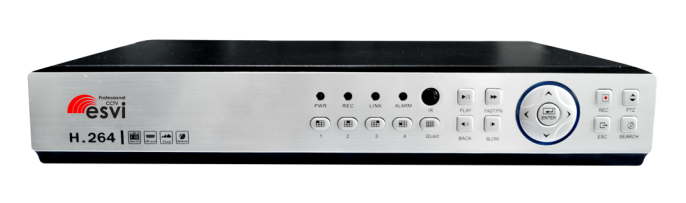
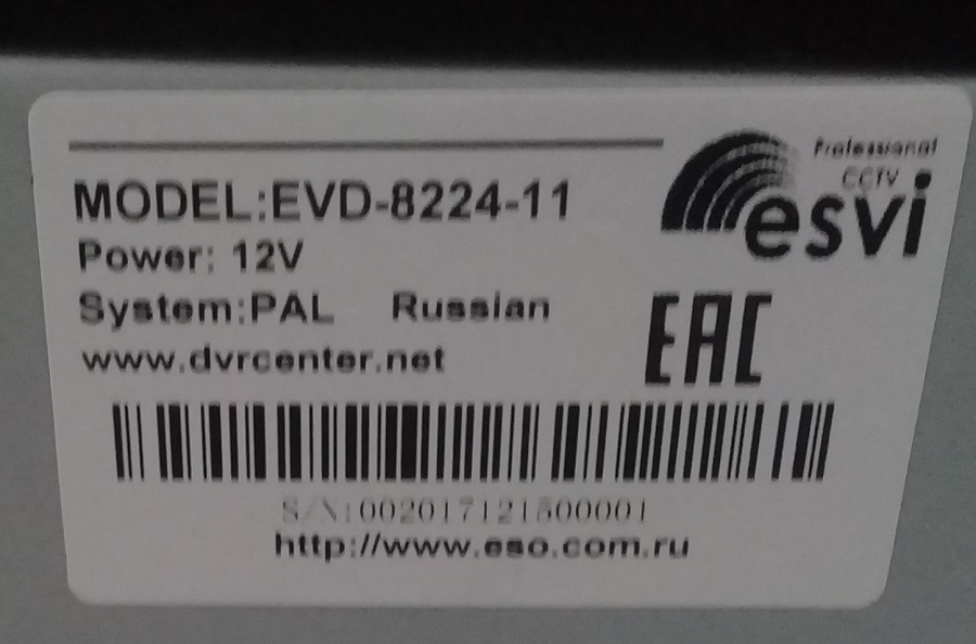
- Модель: EVD-8224-11
- Марка: ESVI
- 24 потока 1080P
- Система
- Процессор: Huawei HIS chipset Hi3535
- Операционная система: Встроенная ОС LINUX
- Интерфейс
- Экран: 1/4/8/16/25
- VGA: 1920х1080
- HDMI: 1920х1080
- Запись
- Алгоритм сжатия видео: H.264 Main Profile
- Алгоритм сжатия аудио: G.711A
- Режимы записи: Ручной/Тревога/Детекция движения/Расписание
- Хранение: Жесткий диск, сеть
- Режимы записи
- Сетевой режим
- 24*1080P (воспр. 4),
- 16*1080P (воспр. 8),
- 8*1080P (воспр. 8),
- 32*960P (воспр. 8),
- 16*720P (воспр. 16),
- 16*3M (воспр. 4),
- 8*5M (воспр. 2)
- Сетевой режим
- Архив
- Режимы поиска: Все/Время/Дата/Событие/Канал
- Резервное копирование: Сеть, USB
- Интерфейс
- Видео входы: —
- Видео выходы: 1*VGA, 1*HDMI
- Аудио входы: 1*RCA
- Аудио выход: 1*RCA
- Тревожный вход: —
- Тревожный выход: —
- Сеть: 1*RJ45 10M/100M
- Сетевые протоколы: HTTP, TCP/IP, DHCP, FTP, RTSP, NTP, PPoE, SMTP, DNS, DDNS, ONVIF
- PTZ: 1*RS485
- PTZ протоколы: Pelco-D, Pelco-P, Sony, Sharp, Panasonic, Samsung.
- USB: 2
- HDD: 2 SATA порта (не более 8 Тб)
- Язык оболочки: English, Russian
- Браузер: Internet Explorer 6-11
- Мобильная платформа: iOS, Android (vMEyeSuper,XMeye, GoodEye)
- Облачный сервис: www.dvrcenter.net
- Эксплуатация
- Температура эксплуатации: 0℃ ~ +50℃ RH95% Max
- Температура хранения: -20℃ ~ +60℃ RH95% Max
- Источник питания: DC 12В, 4А, <10W (без жесткого диска)
- Размеры: 325x236x53 мм
- Вес: 2,5кг (без HDD)
Пароли по умолчанию
Admin — пустой пароль
Default — пустой пароль
Guest — пустой пароль
Если неправильный пароль введен подряд три раза, сработает тревога. Если неправильный пароль введен подряд пять раз, пользователь будет заблокирован. После перезагрузки или через полчаса пользователи будут разблокированы автоматически.
RTSP
rtsp://ip_address:554/user=admin&password=&channel=1&stream=0.sdp?

ip_address	ip адрес устройства
:554		RTSP порт
user=admin  	логин	(admin, по умолчанию)
password=	пароль (пусто, по умолчанию)
channel=1  	1 канал
stream=0.sdp? основной поток
Проблемы
Столкнулись с проблемой, когда видеорегистратор начал дребезжать. Поступила жалоба на устройство:
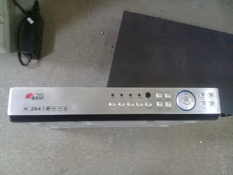
Модель:
Звук такой:
Сначала подозрения пали на вентилятор. Снял крышку:
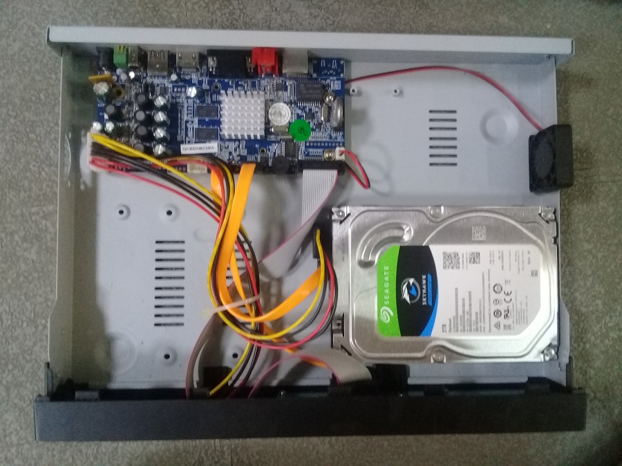
Хм, вентилятор не впечатлил.
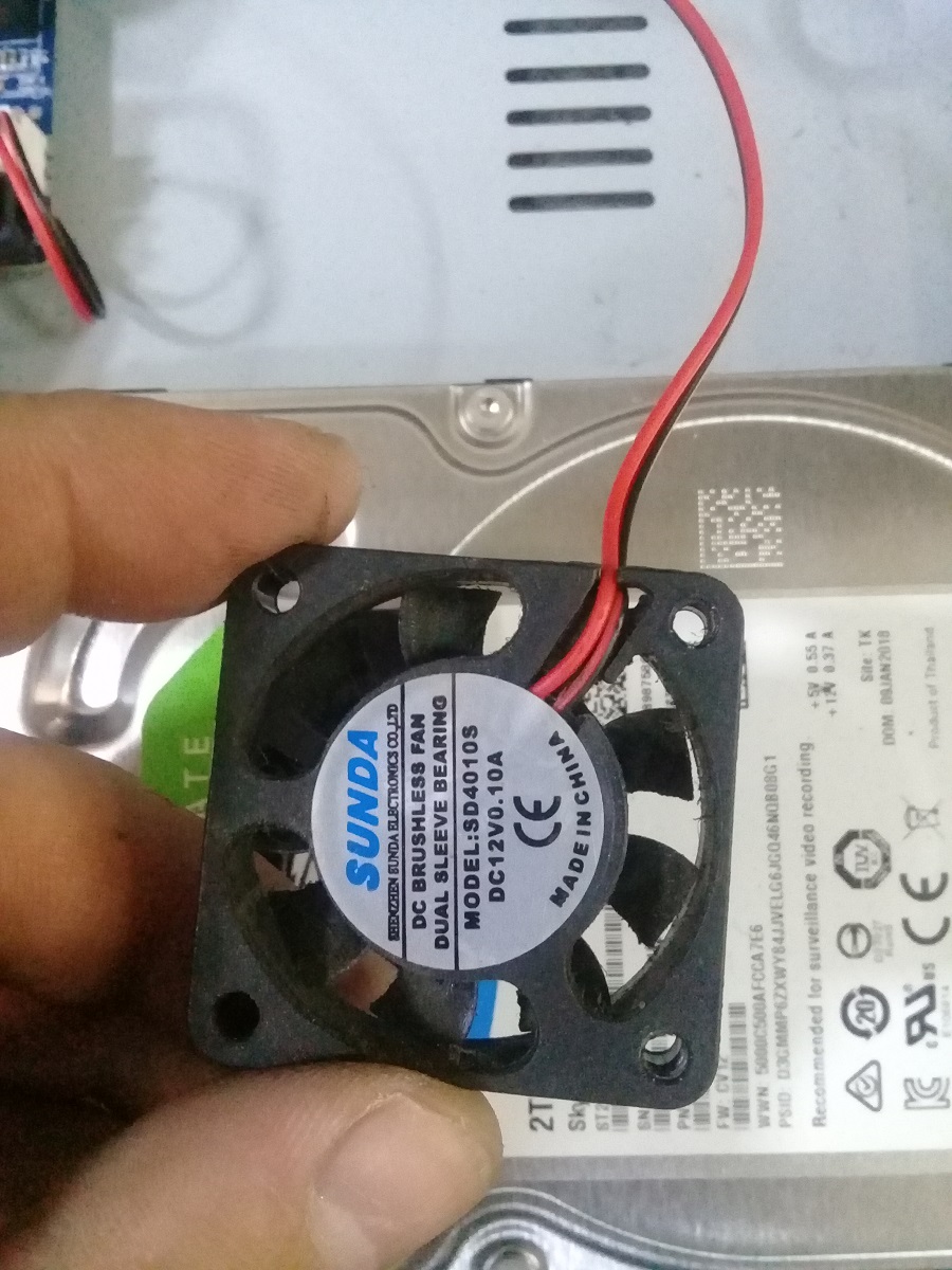
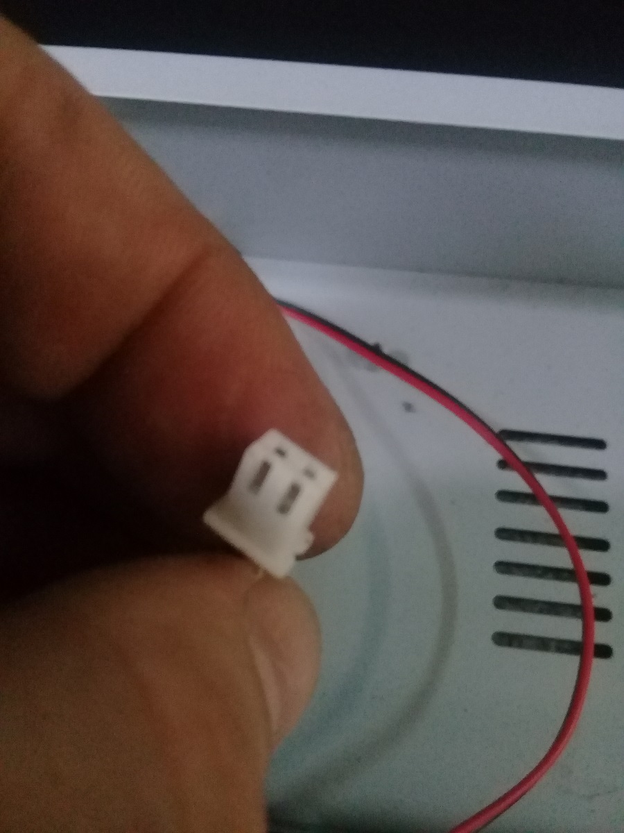
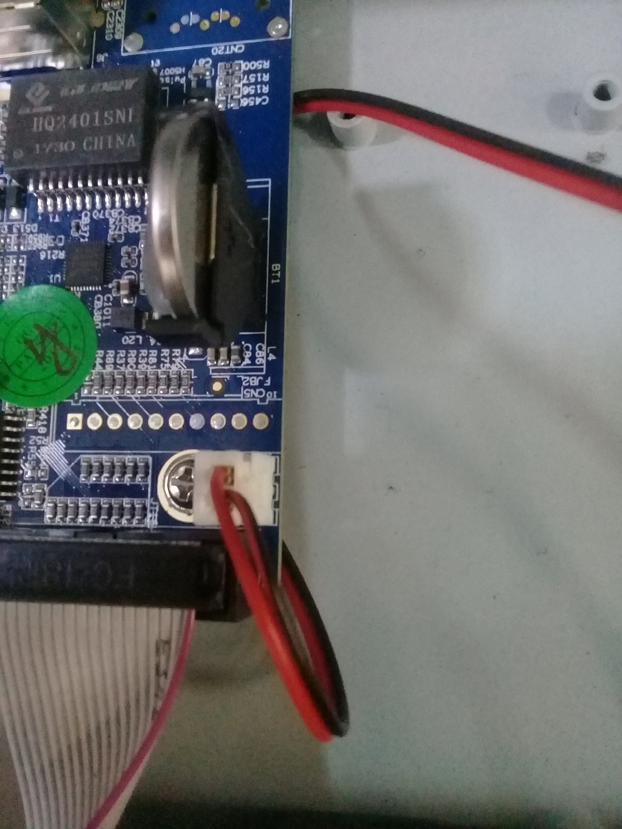
Вентилятор крепится к корпусу двумя винтами и питается от платы.
Не может он так дребезжать. В итоге проблема была найдена — звук издавал жёсткий диск. Было принято решение дождаться, когда диск полностью выйдет из строя, а потом заменить. В итоге диск уже год дребезжит, кряхтит, но продолжает работать.