-
Contents
-
Table of Contents
-
Troubleshooting
-
Bookmarks
Quick Links
Digital Video Recorder
User Manual
UD.6L0202D1623A01
Related Manuals for HIKVISION DVR
Summary of Contents for HIKVISION DVR
-
Page 1: Digital Video Recorder
Digital Video Recorder User Manual UD.6L0202D1623A01…
-
Page 2
The content of this manual is furnished for informational use only, is subject to change without notice, and should not be construed as a commitment by Hangzhou Hikvision Digital Technology Co., Ltd. (Hikvision). Hikvision assumes no responsibility or liability for any errors or inaccuracies that may appear in the book. -
Page 3
User Manual of Digital Video Recorder Regulatory information FCC information This equipment has been tested and found to comply with the limits for a digital device, compliance: pursuant to part 15 of the FCC Rules. These limits are designed to provide reasonable protection against harmful interference when the equipment is operated in a commercial environment. -
Page 4: Preventive And Cautionary Tips
User Manual of Digital Video Recorder Preventive and Cautionary Tips Before connecting and operating your DVR, please be advised of the following tips: • Ensure unit is installed in a well-ventilated, dust-free environment. • Unit is designed for indoor use only.
-
Page 5: Trademarks And Registered Trademarks
User Manual of Digital Video Recorder Trademarks and Registered Trademarks • Windows and Windows mark are trademarks or registered trademarks of Microsoft Corporation in the United States and/or other countries. • HDMI, HDMI mark and High-Definition Multimedia Interface are trademarks or registered trademarks of HDMI Licensing LLC.
-
Page 6
Thank you for purchasing our product. If there is any question or request, please do not hesitate to contact dealer. The figures in this manual are for reference only. This manual is applicable to the models listed in the following table. Series Model Type DS-7100HGHI-SH DS-7104HGHI-SH Network DVR DS-7108HGHI-SH DS-7100HQHI-SH DS-7104HQHI-SH Network HDVR DS-7200HGHI-SH DS-7204HGHI-SH Network HDVR… -
Page 7: Product Key Features
Connectable to HD-TVI and analog cameras; Connectable to the Coaxitron camera/dome with long transmission distance; Connectable to IP cameras from Hikvision for HDVR series; Each channel supports dual-stream. Main stream supports up to 1080P resolution and sub-stream supports up to WD1 resolution;…
-
Page 8
User Manual of Digital Video Recorder 8 recording time periods with separated recording types; Pre-record and post-record for motion detection triggered recording, and pre-record time for schedule and manual recording; Searching record files by events (alarm input/motion detection); … -
Page 9
User Manual of Digital Video Recorder Support access by EZVIZ Cloud P2P. TCP, UDP and RTP for unicast; Auto/Manual port mapping by UPnP Remote search, playback, download, locking and unlocking the record files, and downloading files broken transfer resume;… -
Page 10: Table Of Contents
Input Method Description ………………….26 Rear Panel ……………………….. 27 Chapter 2 Getting Started ……………………..30 Starting Up and Shutting Down the DVR ………………31 Using the Wizard for Basic Configuration………………33 Adding and Connecting the IP Cameras ………………37 2.3.1 Adding the Online IP Cameras…………………
-
Page 11
User Manual of Digital Video Recorder Configuring Motion Detection Record ………………72 Configuring Alarm Triggered Record ……………….. 74 Manual Record ……………………..76 Configuring Holiday Record ………………….77 Configuring Redundant Recording ………………..79 Configuring HDD Group for Recording ………………81 Files Protection ……………………..82 Chapter 6 Playback ………………………. -
Page 12
11.2 Configuring Privacy Mask………………….168 11.3 Configuring Video Parameters ………………..169 Chapter 12 DVR Management and Maintenance …………….170 12.1 Viewing System Information ………………….. 171 12.2 Searching and Exporting Log Files ………………… 171 12.3 Importing/Exporting IP Camera Info ………………. 174 12.4 Importing/Exporting Configuration Files ……………… -
Page 13
13.5.1 Adding a User ……………………183 13.5.2 Deleting a User ……………………185 13.5.3 Editing a User ……………………185 13.6 Logging out/Shutting down/Rebooting Device …………….187 Appendix …………………………188 Glossary …………………………189 Troubleshooting ……………………….. 190 List of Compatible Hikvision IP Cameras ………………..193… -
Page 14: Chapter 1 Introduction
User Manual of Digital Video Recorder Chapter 1 Introduction…
-
Page 15: Front Panels
Table 1. 1 Description of Front Panel Icon Description Indicator turns red when DVR is powered up. Indicator lights in red when data is being read from or written to HDD. Indicator blinks blue when network connection is functioning properly.
-
Page 16
User Manual of Digital Video Recorder Name Function Description Tx/Rx indictor blinks yellow when network connection is Tx/Rx functioning properly. Receiver for IR remote IR Receiver Universal Serial Bus (USB) ports for additional devices such as USB Interfaces USB mouse and USB Hard Disk Drive (HDD). Figure 1. -
Page 17
User Manual of Digital Video Recorder Name Function Description Enter numeral “6”; Enter letters “MNO”; 6/MNO/PLAY In Playback mode, it is used for direct access to playback interface. Enter numeral “7”; Enter letters “PQRS”; 7/PQRS/REC Manual record, for direct access to manual record interface; manually enable/disable record. -
Page 18
1~254; Indicator turns red when the SHIFT button is used; Indicator does not light when the DVR is controlled by a keyboard or by the IR remote control with the address of 255; Indicator turns green when the DVR is controlled by IR remote… -
Page 19
User Manual of Digital Video Recorder Name Function Description Enter numeral “7”; Enter letters “PQRS”; 7/PQRS/REC Manual record, for direct access to manual record interface; manually enable/disable record. Enter numeral “8”; Enter letters “TUV”; 8/TUV/PTZ Access PTZ control interface. Enter numeral “9”; Enter letters “WXYZ”;… -
Page 20
Indicator turns red when controlled by a keyboard and orange when STATUS IR remote and keyboard is used at the same time. Indicator does not light when the DVR is controlled by the IR remote Status control with the address of 255. -
Page 21
USB Hard Disk Drive (HDD). Exit and back to the previous menu. Arm/disarm the DVR in live view mode. Enter the Manual Record setting menu. In PTZ control settings, press the button and then you can call a PTZ REC/SHOT preset by pressing Numeric button. -
Page 22
User Manual of Digital Video Recorder Name Function Description In Playback mode, it is used to show/hide the control interface. Switch between single screen and multi-screen mode. PREV/FOCUS- In PTZ Control mode, it is used to adjust the focus in conjunction with the A/FOCUS+ button. -
Page 23: Ir Remote Control Operations
User Manual of Digital Video Recorder 1.2 IR Remote Control Operations The DVR may also be controlled with the included IR remote control, shown in Figure 1. 7. Batteries (2× AAA) must be installed before operation. Figure 1. 7 Remote Control The keys on the remote control closely resemble the ones found on the front panel.
-
Page 24
Go into Menu > Settings > General > More Settings by operating the front control panel or the mouse. Check and remember DVR ID#. The default ID# is 255. This ID# is valid for all IR remote controls. Press the DEV button on the remote control. -
Page 25: Usb Mouse Operation
User Manual of Digital Video Recorder 1.3 USB Mouse Operation A regular 3-button (Left/Right/Scroll-wheel) USB mouse can also be used with this DVR. To use a USB mouse: Steps: 1. Plug USB mouse into one of the USB interfaces on the front panel of the DVR.
-
Page 26: Input Method Description
User Manual of Digital Video Recorder 1.4 Input Method Description Figure 1. 8 Soft Keyboard Description of the buttons on the soft keyboard: Table 1. 8 Description of the Soft Keyboard Icons Icons Description Icons Description English Capital English Numbers Symbols Lowercase/Uppercase Backspace…
-
Page 27: Rear Panel
User Manual of Digital Video Recorder 1.5 Rear Panel Figure 1. 9 DS-7100HGHI-SH and DS-7100HQHI-SH Table 1. 9 Description of Front Panel Item Description VIDEO IN BNC interface for TVI and analog video input. HDMI HDMI video output connector. DB15 connector for VGA output. Display local video output and menu. AUDIO OUT RCA connector.
-
Page 28
User Manual of Digital Video Recorder Power Switch Switch for turning on/off the device. Ground Alarm In/Out (for Connectors for alarm inputs and alarm outputs. DS-7200HQHI-SH) Figure 1. 12 DS-7300HQHI-SH and DS-7300HGHI-SH Figure 1. 13 DS-8100HGHI-SH Figure 1. 14 DS-8100HQHI-SH Table 1. -
Page 29
PTZ receiver respectively. D+, D- pin connects to Ta, Tb pin of controller. For cascading devices, the first DVR’s D+, D- pin should be connected with the D+, D- pin of the next DVR. Connector for alarm input. -
Page 30: Chapter 2 Getting Started
User Manual of Digital Video Recorder Chapter 2 Getting Started…
-
Page 31: Starting Up And Shutting Down The Dvr
Proper startup and shutdown procedures are crucial to expanding the life of the DVR. Before you start: Check that the voltage of the extra power supply is the same with the DVR’s requirement, and the ground connection is working properly.
-
Page 32
While in the Shutdown menu (Figure 2. 1), you can also reboot the DVR. Steps: 1. Enter the Shutdown menu by clicking Menu > Shutdown. 2. Click the Logout button to log out or the Reboot button to reboot the DVR. -
Page 33: Using The Wizard For Basic Configuration
Figure 2. 3 Language Selection 2. The Setup Wizard can walk you through some important settings of the DVR. If you do not want to use the Setup Wizard at this time, click the Cancel button. You can also choose to use the Setup Wizard next time by leaving the “Start wizard when device starts?”…
-
Page 34
User Manual of Digital Video Recorder Figure 2. 5 Login Window 4. Enter the admin password. By default, the password is 12345. You are highly recommended to change the default password right after the first login to avoid safety problem. 5. -
Page 35
User Manual of Digital Video Recorder Figure 2. 7 General Network Configuration 1 self-adaptive 10M/100M network interface is provided for DS-7204HGHI-SH; 2 self-adaptive 10M/100M/1000M network interfaces for DS-8100HQHI&HGHI-SH series, and three working modes are configurable: multi-address, load balance, network fault tolerance; and 1 self-adaptive 10M/100M/1000M network interface for other models. -
Page 36
User Manual of Digital Video Recorder Figure 2. 9 HDD Management 11. To initialize the HDD, click the Init button. Initialization will remove all the data saved in the HDD. 12. Click Next button to enter the Record Settings window, as shown in Figure 2. 10. Figure 2. -
Page 37: Adding And Connecting The Ip Cameras
User Manual of Digital Video Recorder 2.3 Adding and Connecting the IP Cameras This section is not available for the DS-7100-SH series DVR. 2.3.1 Adding the Online IP Cameras Purpose: The main function of the NVR is to connect the network cameras and record the video got from it. So before you can get a live view or record of the video, you should add the network cameras to the connection list of the device.
-
Page 38
User Manual of Digital Video Recorder Figure 2. 12 Adding IP Camera Interface 3. The online cameras with same network segment will be displayed in the camera list. Click the button to add the camera. Or you can click the Add All button to add all the detected online IP cameras. Table 2. -
Page 39
User Manual of Digital Video Recorder 3) Click Add to add the camera. OPTION 2: Steps: 1. Enter the Camera Management interface. Menu> Camera> Camera Figure 2. 14 Main Menu 2. Repeat the step 3 and 4 of OPTION 1 to add the camera. Figure 2. -
Page 40: Editing The Connected Ip Cameras And Configuring Customized Protocols
User Manual of Digital Video Recorder Figure 2. 16 Selecting Multiple Channels 2.3.2 Editing the Connected IP Cameras and Configuring Customized Protocols After the adding of the IP cameras, the basic information of the camera lists in the page, you can configure the basic setting of the IP cameras.
-
Page 41
User Manual of Digital Video Recorder Figure 2. 18 Network Configuration of the Camera 2. You can edit the network information and the password of the camera. Figure 2. 19 Password Configuration of the Camera 3. Click Apply to save the settings and click OK to exit the interface. -
Page 42: Chapter 3 Live View
User Manual of Digital Video Recorder Chapter 3 Live View…
-
Page 43: Introduction Of Live View
3.1 Introduction of Live View Live view shows you the video image getting from each camera in real time. The DVR will automatically enter Live View mode when powered on. It is also at the very top of the menu hierarchy, thus hitting the ESC many times (depending on which menu you’re on) will bring you to the Live View mode.
-
Page 44: Operations In Live View Mode
Playback: play back the recorded videos for current day. • Aux/Main output switch: the DVR checks the connection of the output interfaces to define the main and auxiliary output interfaces. The priority level for the main and aux output is HDMI>VGA>CVBS. This means if the HDMI is used, it will be the main output.
-
Page 45: Using The Mouse In Live View
User Manual of Digital Video Recorder 3.2.2 Using the Mouse in Live View Table 3. 4 Mouse Operation in Live View Name Description Menu Enter the main menu of the system by right clicking the mouse. Single Screen Switch to the single full screen by choosing channel number from the dropdown list.
-
Page 46: Using An Auxiliary Monitor
User Manual of Digital Video Recorder The Add IP Camera is not supported by DS-7100-SH series DVR. 3.2.3 Using an Auxiliary Monitor Certain features of the Live View are also available while in an Aux monitor. These features include: •…
-
Page 47: Quick Setting Toolbar In Live View Mode
Image Settings Close Live View The DS-7100-SH series DVR does not support the RS-485 interface, thus the PTZ control function is not applicable to it. Instant Playback only shows the record in last five minutes. If no record is found, it means there is no record during the last five minutes.
-
Page 48
User Manual of Digital Video Recorder Image Settings icon can be selected to enter the Image Settings menu. Four modes are selectable according to the real situation: • Standard: for general lighting conditions (default). • Indoor: the image is relatively smoother. •… -
Page 49: Channel-Zero Encoding
User Manual of Digital Video Recorder 3.3 Channel-zero Encoding This chapter is applicable to DS-7300 and DS-8100 series only. Purpose: Sometimes you need to get a remote view of many channels in real time from web browser or CMS (Client Management System) software, in order to decrease the bandwidth requirement without affecting the image quality, channel-zero encoding is supported as an option for you.
-
Page 50: Adjusting Live View Settings
User Manual of Digital Video Recorder 3.4 Adjusting Live View Settings Purpose: Live View settings can be customized according to different needs. You can configure the output interface, dwell time for screen to be shown, mute or turning on the audio, the screen number for each channel, etc. Steps: 1.
-
Page 51
User Manual of Digital Video Recorder 2) Click a window to select it, and then double-click a camera name in the camera list you would like to display. Setting an ‘X’ means the window will not display any camera. 3) You can also click to start live view of all channels in order and click to stop live view of all channels. -
Page 52: Manual Video Quality Diagnostics
User Manual of Digital Video Recorder 3.5 Manual Video Quality Diagnostics Purpose: The video quality of the analog channels can be diagnosed manually and you can view the diagnostic results from a list. Steps: 1. Enter the Manual Video Quality Diagnostics interface. Menu>…
-
Page 53: User Logout
User Manual of Digital Video Recorder 3.6 User Logout Purpose: After logging out, the monitor turns to the live view mode and if you want to do some operation, you need to enter user name and password to log in again. Steps: 1.
-
Page 54: Chapter 4 Ptz Controls
User Manual of Digital Video Recorder Chapter 4 PTZ Controls…
-
Page 55: Configuring Ptz Settings
User Manual of Digital Video Recorder 4.1 Configuring PTZ Settings Purpose: Follow the procedure to set the parameters for PTZ. The configuring of the PTZ parameters should be done before you control the PTZ camera. Steps: 1. Enter the PTZ Settings interface. Menu >Camera>…
-
Page 56
User Manual of Digital Video Recorder For the Coaxitron camera/dome connected, you can select the PTZ protocol to HIKVISION-C (Coaxitron) or PELCO-C (Coaxitron). Make sure the protocol selected here is supported by the connected camera/dome. When the Coaxitron protocol is selected, all the other parameters like the baud rate, data bit, stop bit, parity and flow control are not configurable. -
Page 57: Setting Ptz Presets, Patrols & Patterns
User Manual of Digital Video Recorder 4.2 Setting PTZ Presets, Patrols & Patterns Before you start: Please make sure that the presets, patrols and patterns should be supported by PTZ protocols. 4.2.1 Customizing Presets Purpose: Follow the steps to set the Preset location which you want the PTZ camera to point to when an event takes place.
-
Page 58: Customizing Patrols
5. Click the Call Preset button to call it. When the Coaxitron camera/dome connected and the PTZ protocol is selected to HIKVISION-C (Coaxitron) or PELCO-C (Coaxitron), you can call the preset 95 to enter the menu of the connected Coaxitron camera/dome.
-
Page 59: Calling Patrols
User Manual of Digital Video Recorder Figure 4. 5 PTZ Settings 2. Select patrol No. in the drop-down list of patrol. 3. Click the Set button to add key points for the patrol. Figure 4. 6 Key point Configuration 4. Configure key point parameters, such as the key point No., duration of staying for one key point and speed of patrol.
-
Page 60: Customizing Patterns
User Manual of Digital Video Recorder 2. Click the button to show the general settings of the PTZ control. Figure 4. 7 PTZ Panel — General 3. Select a patrol in the dropdown list and click the Call Patrol button to call it. 4.
-
Page 61: Calling Patterns
User Manual of Digital Video Recorder 4.2.6 Calling Patterns Purpose: Follow the procedure to move the PTZ camera according to the predefined patterns. Steps: 1. Click the button PTZ in the lower-right corner of the PTZ setting interface; Or press the PTZ button on the front panel or click the PTZ Control icon in the quick setting bar, or select the PTZ option in the right-click menu to show the PTZ control panel.
-
Page 62: Calling Linear Scan
User Manual of Digital Video Recorder Figure 4. 10 PTZ Settings 2. Use the directional button to wheel the camera to the location where you want to set the limit, and click the Left Limit or Right Limit button to link the location to the corresponding limit. The speed dome starts linear scan from the left limit to the right limit, and you must set the left limit on the left side of the right limit, as well the angle from the left limit to the right limit should be no more than 180º…
-
Page 63: One-Touch Park
User Manual of Digital Video Recorder You can click the Restore button to clear the defined left limit and right limit data and the dome needs to reboot to make settings take effect. 4.2.9 One-touch Park Purpose: For some certain model of the speed dome, it can be configured to start a predefined park action (scan, preset, patrol and etc.) automatically after a period of inactivity (park time).
-
Page 64: Ptz Control Panel
User Manual of Digital Video Recorder 4.3 PTZ Control Panel To enter the PTZ control panel, there are two ways supported. OPTION 1: In the PTZ settings interface, click the PTZ button on the lower-right corner which is next to the Back button. OPTION 2: In the Live View mode, you can press the PTZ Control button on the front panel or on the remote control, or choose the PTZ Control icon…
-
Page 65: Chapter 5 Recording Settings
User Manual of Digital Video Recorder Chapter 5 Recording Settings…
-
Page 66: Configuring Encoding Parameters
User Manual of Digital Video Recorder 5.1 Configuring Encoding Parameters Before you start: 1. Make sure that the HDD has already been installed. If not, please install a HDD and initialize it. (Menu>HDD>General) Figure 5. 1 HDD- General 2. Click Advance to check the storage mode of the HDD. 1) Whether the HDD mode is Quota, please set the maximum record capacity.
-
Page 67
The Input Resolution of camera connected will be displayed in the live view for 5 seconds when the camera is connected, or the DVR is powered on. The input resolution includes the resolution and frame rate of the camera, e.g. 1080P25. -
Page 68
User Manual of Digital Video Recorder Figure 5. 4 Copy Camera Settings 3. Set encoding parameters for sub-stream. 1) Select the Substream tab. Figure 5. 5 Sub-stream Encoding 2) Select a camera in the camera dropdown list. 3) Configure the parameters. 4) Click Apply to save the settings. -
Page 69: Configuring Record Schedule
User Manual of Digital Video Recorder 5.2 Configuring Record Schedule Purpose: Set the record schedule, and then the camera will automatically start/stop recording according to the configured schedule. Steps: 1. Enter the Record Schedule interface. Menu> Record> Schedule DS-7100-SH and DS-7200HGHI-SH Other Models Figure 5.
-
Page 70
User Manual of Digital Video Recorder Figure 5. 7 Edit Schedule- All Day To arrange other schedule, leave the All Day checkbox blank and set the Start/End time. Figure 5. 8 Edit Schedule- Set Time Period Up to 8 periods can be configured for each day. And the time periods cannot be overlapped with each other. Repeat the above steps 1)-4) to schedule recording for other days in the week. -
Page 71
User Manual of Digital Video Recorder Figure 5. 10 Draw the Schedule Descriptions of the color icons are shown in the figure below. Figure 5. 11 Descriptions of the Color Icons Click and drag the mouse on the schedule. Click on the other area except for the schedule table to finish and exit the drawing. You can repeat step 4 to set schedule for other channels. -
Page 72: Configuring Motion Detection Record
Follow the steps to set the motion detection parameters. In the live view mode, once a motion detection event takes place, the DVR can analyze it and do many actions to handle it. Enabling motion detection function can trigger certain channels to start recording, or trigger full screen monitoring, audio warning, notifying the surveillance center, sending email and so on.
-
Page 73
User Manual of Digital Video Recorder Figure 5. 14 Motion Detection Settings 5) Select the channels which you want the motion detection event to trigger recording. 6) Click Apply to save the settings. 7) Click OK to back to the upper level menu. Exit the Motion Detection menu.
 -
Page 74: Configuring Alarm Triggered Record
User Manual of Digital Video Recorder 5.4 Configuring Alarm Triggered Record The DS-7100-SH and DS-7200HGHI-SH series do not support the alarm input by default. Purpose: Follow the procedure to configure alarm triggered recording. Steps: 1. Enter the Alarm setting interface. Menu>…
-
Page 75
User Manual of Digital Video Recorder Check the checkbox to select channel. Click Apply to save settings. Click OK to back to the upper level menu. Repeat the above steps to configure other alarm input parameters. If the setting can also be applied to other alarm inputs, click Copy and choose the alarm input number. Figure 5. -
Page 76: Manual Record
User Manual of Digital Video Recorder 5.5 Manual Record Purpose: Follow the steps to set parameters for the manual record. Using manual record, you don’t need to set a schedule for recording. Steps: 1. Enter the Manual settings interface. Menu> Manual Figure 5.
-
Page 77: Configuring Holiday Record
User Manual of Digital Video Recorder 5.6 Configuring Holiday Record Purpose: Follow the steps to configure the record schedule on holiday for that year. You may want to have different plan for recording on holiday. Steps: 1. Enter the Record setting interface. Menu>Record 2.
-
Page 78
User Manual of Digital Video Recorder 4. Configure the record schedule. Please refer to the Chapter 5.2 Configuring Record Schedule, while you may choose Holiday in the Schedule dropdown list, or you can draw the schedule on the timeline of Holiday. See the two figures below. -
Page 79: Configuring Redundant Recording
User Manual of Digital Video Recorder 5.7 Configuring Redundant Recording Purpose: Enabling redundant recording, which means saving the record files not only in the R/W HDD but also in the redundant HDD, will effectively enhance the data safety and reliability. Before you start: You must set the Storage mode in the HDD advanced settings to Group before you set the HDD property to Redundant.
-
Page 80
User Manual of Digital Video Recorder Figure 5. 26 Encoding Parameters 2) Select Camera you want to configure. 3) Check the checkbox of Redundant Record. 4) Click Apply to save settings. If the encoding parameters can also be used to other channels, click Copy and choose the channel you want to apply the settings. -
Page 81: Configuring Hdd Group For Recording
User Manual of Digital Video Recorder 5.8 Configuring HDD Group for Recording Purpose: You can group the HDDs and save the record files in certain HDD group. Steps: 1. Enter HDD setting interface. Menu>HDD>Advanced 2. Select Advanced on the left bar. Check whether the storage mode of the HDD is Group.
-
Page 82: Files Protection
User Manual of Digital Video Recorder 5.9 Files Protection Purpose: You can lock the recorded files or set the HDD property to Read-only to protect the record files from being overwritten. Protect file by locking the record files Steps: 1. Enter Playback setting interface. Menu>…
-
Page 83
If there is only one HDD and is set to Read-only, the DVR cannot record any files. Only live view mode is available. If you set the HDD to Read-only when the DVR is saving files in it, then the file will be saved in next R/W HDD. If there is only one HDD, the recording will be stopped. -
Page 84: Chapter 6 Playback
User Manual of Digital Video Recorder Chapter 6 Playback…
-
Page 85: Playing Back Record Files
User Manual of Digital Video Recorder 6.1 Playing Back Record Files 6.1.1 Playing Back by Channel Purpose: Play back the recorded video files of a specific channel in the live view mode. Channel switch is supported. OPTION 1 Choose a channel in live view mode using the mouse and click the button in the quick setting toolbar.
-
Page 86
User Manual of Digital Video Recorder DS-7100 and DS-7200 DS-7300 and DS-8100 Figure 6. 2 Right-click Menu under Live View Front Panel: press PLAY button to play back recording files of the channel under single-screen live view mode. Under multi-screen live view mode, the recorded files of the top-left channel will be played back. For the DS-7300 and DS-8100, pressing numerical buttons will switch playback to the corresponding camera during playback process. -
Page 87: Playing Back By Time
User Manual of Digital Video Recorder Figure 6. 4 Toolbar of Playback Table 6. 1 Detailed Explanation of Playback Toolbar Button Operation Button Operation Button Operation Audio on/ Mute Start/Stop clipping Save clip(s) Add default tag Add customized tag Tag management Pause / Reverse play/ Digital Zoom Smart Search…
-
Page 88
User Manual of Digital Video Recorder Figure 6. 5 Playback Calendar If there are record files for that camera in that day, in the calendar, the icon for that day is displayed as . Otherwise it is displayed as In the Playback interface: The toolbar in the bottom part of Playback interface can be used to control playing process, as shown in Figure 6. -
Page 89: Playing Back By Event Search
User Manual of Digital Video Recorder Pause play/ Play/ Stop 30s reverse Single-frame play 30s forward Speed down Speed up Scaling up/down the Previous day Next day time line Full Screen Exit Video type Process bar Video type bar The indicates the start time and end time of the record files.
-
Page 90
User Manual of Digital Video Recorder Figure 6. 9 Search Result Bar 5. Click button to play back the file. You can click the Back button to back to the search interface. Pre-play and post-play can be configured. 6. (Optional) If multiple channels are triggered recording by the alarm input, clicking the button will pop up a synchoronouse playback channel selection window. -
Page 91: Playing Back By Tag
User Manual of Digital Video Recorder Figure 6. 11 Toolbar of Playback by Event Table 6. 3 Detailed Explanation of Playback-by-event Toolbar Button Operation Button Operation Button Operation Audio on/ Mute Start/Stop clipping Save clip(s) Add default tag Add customized tag Tag management Pause / Reverse play/ Smart Search…
-
Page 92
User Manual of Digital Video Recorder Figure 6. 12 Interface of Playback by Time Click button to add default tag. Click button to add customized tag and input tag name. Max. 64 tags can be added to a single video file. 3. -
Page 93
User Manual of Digital Video Recorder Figure 6. 14 Video Search by Tag 3. Click button to play back the file. You can click the Back button to back to the search interface. Pre-play and post-play can be configured. Figure 6. 15 Interface of Playback by Tag Figure 6. -
Page 94: Smart Playback
User Manual of Digital Video Recorder Table 6. 4 Detailed Explanation of Playback-by-tag Toolbar Button Operation Button Operation Button Operation Audio on/ Mute Start/Stop clipping Save clip(s) Add default tag Add customized tag Tag management Pause / Reverse play/ Digital Zoom Smart Search Single-frame reverse play…
-
Page 95: Playing Back By System Logs
User Manual of Digital Video Recorder Figure 6. 17 Smart Playback Interface Table 6. 5 Detailed Explanation of Smart Playback Toolbar Button Operation Button Operation Button Operation Scaling Pause play/ Stop up/down the Play time line Smart search Video type / Process bar result picture…
-
Page 96
User Manual of Digital Video Recorder Figure 6. 18 System Log Search Interface 2. Click Log Search tab to enter Playback by System Logs. Set search time and type and click Search button. Figure 6. 19 Result of System Log Search 3. -
Page 97: Playing Back External File
User Manual of Digital Video Recorder Figure 6. 20 Interface of Playback by Log 6.1.7 Playing Back External File Purpose: Perform the following steps to look up and play back files in the external devices. Steps: 1. Enter Tag Search interface. Menu>Playback 2.
-
Page 98: Auxiliary Functions Of Playback
User Manual of Digital Video Recorder 6.2 Auxiliary Functions of Playback 6.2.1 Playing Back Frame by Frame Purpose: Play video files frame by frame, in order to check image details of the video when abnormal events happen. Steps: • Using a Mouse Go to Playback interface and click button until the speed changes to Single frame.
-
Page 99
User Manual of Digital Video Recorder 3. Click and drag the mouse to draw area(s). You can click button to set the full screen as target searching area. After drawing area(s), press button to execute smart search in this area. Multi-area and full-screen searching modes are supported. -
Page 100: Digital Zoom
User Manual of Digital Video Recorder 6.2.3 Digital Zoom Steps: 1. Click the button on the playback control bar to enter Digital Zoom interface. 2. Use the mouse to draw a red rectangle and the image within it will be enlarged up to 16 times. Figure 6.
-
Page 101
User Manual of Digital Video Recorder Figure 6. 27 4-ch Synchronous Playback Interface 3. Click to play back the record files reversely. -
Page 102: Chapter 7 Backup
User Manual of Digital Video Recorder Chapter 7 Backup…
-
Page 103: Backing Up Record Files
User Manual of Digital Video Recorder 7.1 Backing up Record Files Before you start: Please insert the backup device(s) into the device. 7.1.1 Backing up by Normal Video Search Purpose: The record files can be backed up to various USB devices, such as USB flash drives, USB HDDs, and USB writer.
-
Page 104
User Manual of Digital Video Recorder 4. Export. Click Export button and start backup. If the inserted USB device is not recognized: • Click the Refresh button. • Reconnect device. • Check for compatibility from vendor. You can also format the USB device by clicking the Format button. Figure 7. -
Page 105
User Manual of Digital Video Recorder This function is supported by DS-7300 and DS-8100 series DVR. Steps: 1. Enter Record>Advanced and set the usage of eSATA HDD at “Export”. Menu>Record>Advanced Choose eSATA and set its usage at Export. Click Yes when pop-up message box “System will reboot automatically if the usage of eSATA is changed. -
Page 106: Backing Up By Event Search
User Manual of Digital Video Recorder Figure 7. 6 Export by Normal Video Search Using eSATA HDD Stay in the Exporting interface until all record files are exported with pop-up message “Export finished”. 5. Check backup result. Choose the record file in Export interface and click button to check it.
-
Page 107
User Manual of Digital Video Recorder Here we take the backup by motion detection as the example. Backup by alarm input is supported by DS-7300 and DS-8100 series DVR. 2) Check the checkbox of cameras and set the search time. -
Page 108
User Manual of Digital Video Recorder Figure 7. 10 Event Details Interface 4. Export. Click the Export button and start backing up. If the inserted USB device is not recognized: • Click the Refresh button. • Reconnect device. • Check for compatibility from vendor. You can also format USB flash drive or USB HDDs via the device. -
Page 109: Backing Up Video Clips
User Manual of Digital Video Recorder Figure 7. 12 Checkup of Event Export Result Using USB Flash Drive 7.1.3 Backing up Video Clips Purpose: You may also select video clips to export directly during Playback, using USB devices, such as USB flash drives, USB HDDs, and USB writers.
-
Page 110
User Manual of Digital Video Recorder Figure 7. 14 Clips Export Up to 30 items of video clips can be selected for backup at one time. 4. Click the button Export to export the selected video clips to the backup device. If the inserted USB device is not recognized: •… -
Page 111
User Manual of Digital Video Recorder 6. Click Yes to save video clips and enter Export interface, or click No to quit without saving video clips. 7. Check backup result. The Player player.exe will be exported automatically during record file export. Figure 7. -
Page 112: Managing Backup Devices
User Manual of Digital Video Recorder 7.2 Managing Backup Devices Steps: 1. Enter Search Result interface of record files. Menu>Export>Normal Set search condition and click Search button to enter Search Result interface. At least one channel shall be selected. Figure 7. 18 Normal Video Search for Backup 2.
-
Page 113
User Manual of Digital Video Recorder Figure 7. 20 USB Flash Drive Management Click New Folder button if you want to create a new folder in the backup device. Select a record file or folder in the backup device and press button if you want to delete it. -
Page 114: Chapter 8 Alarm Settings
User Manual of Digital Video Recorder Chapter 8 Alarm Settings…
-
Page 115: Setting Motion Detection
User Manual of Digital Video Recorder 8.1 Setting Motion Detection Steps: 1. Enter Motion Detection interface of Camera Management and choose a camera you want to set up motion detection. Menu> Camera> Motion Figure 8. 1 Motion Detection Setup Interface 2.
-
Page 116
User Manual of Digital Video Recorder Time periods shall not be repeated or overlapped. Figure 8. 4 Set Arming Schedule of Motion Detection 5. Click Linkage Action tab to set up alarm response actions of motion alarm (please refer to Chapter 8.7 Setting Alarm Response Actions). -
Page 117: Setting Sensor Alarms
User Manual of Digital Video Recorder 8.2 Setting Sensor Alarms This function is not supported by DS-7100-SH and DS-7200HGHI-SH series. Purpose: Set up handling method of an external sensor alarm. Steps: 1. Enter Alarm Settings of System Configuration and select an alarm input. Menu>…
-
Page 118
User Manual of Digital Video Recorder Figure 8. 7 Set Arming Schedule of Alarm Input 5. Select Linkage Action tab to set up alarm response actions of the alarm input (please refer to Chapter 8.7 Setting Alarm Response Actions). Repeat the above steps to set up arming schedule of other days of a week. You can also use Copy button to copy an arming schedule to other days. -
Page 119
User Manual of Digital Video Recorder Figure 8. 9 Copy Settings of Alarm Input… -
Page 120: Detecting Video Loss
User Manual of Digital Video Recorder 8.3 Detecting Video Loss Purpose: Detect video loss of a channel and take alarm response action(s). Steps: 1. Enter Video Loss interface of Camera Management and select a channel you want to detect. Menu> Camera> Video Loss Figure 8.
-
Page 121
User Manual of Digital Video Recorder 4. Select Linkage Action tab to set up alarm response action of video loss (please refer to Chapter 8.7 Setting Alarm Response Actions). 5. Click the OK button to complete the video loss settings of the channel. Repeat the above steps to finish settings of other channels, or click the Copy button copy the above settings to them. -
Page 122: Detecting Video Tampering
User Manual of Digital Video Recorder 8.4 Detecting Video Tampering Purpose: Trigger alarm when the lens is covered and take alarm response action(s). Steps: 1. Enter Video Tampering interface of Camera Management and select a channel you want to detect video tampering.
-
Page 123
User Manual of Digital Video Recorder Chapter 8.7 Setting Alarm Response Actions). Repeat the above steps to set arming schedule of other days of a week. You can also use Copy button to copy an arming schedule to other days. 4) Click the OK button to complete the video tampering settings of the channel. -
Page 124: Setting All-Day Video Quality Diagnostics
User Manual of Digital Video Recorder 8.5 Setting All-day Video Quality Diagnostics Purpose: The device provides two ways to diagnose the video quality: manual and all-day. Perform the following steps to set the threshold of the diagnosing and the linkage actions. Steps: 1.
-
Page 125: Handling Exceptions
User Manual of Digital Video Recorder 8.6 Handling Exceptions Purpose: Exception settings refer to the handling method of various exceptions, e.g. • HDD Full: The HDD is full. • HDD Error: Writing HDD error, unformatted HDD, etc. • Network Disconnected: Disconnected network cable. •…
-
Page 126
User Manual of Digital Video Recorder Figure 8. 16 Detailed Event 3. Set the alarm linkage actions. For details, see Chapter 8.7 Setting Alarm Response Actions. 4. Click Apply to save the settings. -
Page 127: Setting Alarm Response Actions
Please refer to Chapter 9.2.11 Configuring Email for details of Email configuration. Trigger Alarm Output Trigger an alarm output when an alarm is triggered. This function is not supported by DS-7100HGHI-SH and DS-7200HGHI-SH series DVR. Steps: 1. Enter Alarm Output interface.
-
Page 128
User Manual of Digital Video Recorder Figure 8. 17 Alarm Output Settings Interface 2. Set up arming schedule of the alarm output. Choose one day of a week and up to 8 time periods can be set within each day. Time periods shall not be repeated or overlapped. -
Page 129: Triggering Or Clearing Alarm Output Manually
User Manual of Digital Video Recorder 8.8 Triggering or Clearing Alarm Output Manually This function is not supported by DS-7100-SH and DS-7200HGHI-SH series. Purpose: Sensor alarm can be triggered or cleared manually. If “Manually Clear” is selected in the dropdown list of dwell time of an alarm output, the alarm can be cleared only by clicking Clear button in the following interface.
-
Page 130: Chapter 9 Network Settings
User Manual of Digital Video Recorder Chapter 9 Network Settings…
-
Page 131: Configuring General Settings
User Manual of Digital Video Recorder 9.1 Configuring General Settings Purpose: Network settings must be properly configured before you operate DVR over network. Steps: 1. Enter the Network Settings interface. Menu > Configuration > Network DS-8100HGHI&HQHI-SH Other Models Figure 9. 1 Network Settings Interface 1 self-adaptive 10M/100M network interface is provided for DS-7204HGHI-SH;…
-
Page 132
User Manual of Digital Video Recorder The valid value of MTU is from 500 to 1500. 4. After having configured the general settings, click the Apply button to save the settings. Working Mode There are two 10M/100M/1000M NIC cards provided by the DS-8100HGHI&HQHI-SH series devices, and it allows the device to work in the Multi-address, Load Balance and Net-fault Tolerance modes. -
Page 133: Configuring Advanced Settings
Purpose: EZVIZ Cloud P2P provides the mobile phone application and as well the service platform page to access and manage your connected DVR, which enables you to get a convenient remote access to the surveillance system. Steps: 1. Enter the Network Settings interface.
-
Page 134: Configuring Ddns
Configuring DDNS Purpose: If your DVR is set to use PPPoE as its default network connection, you may set Dynamic DNS (DDNS) to be used for network access. Prior registration with your ISP is required before configuring the system to use DDNS.
-
Page 135
2) Enter the Device Domain Name. You can use the alias you registered in the HiDDNS server or define a new device domain name. If a new alias of the device domain name is defined in the DVR, it will replace the old one registered on the server. You can register the alias of the device domain… -
Page 136
User Manual of Digital Video Recorder name in the HiDDNS server first and then enter the alias to the Device Domain Name in the DVR; you can also enter the domain name directly on the DVR to create a new one. -
Page 137: Configuring Ntp Server
5. Click the Apply button to save and exit the interface. 9.2.3 Configuring NTP Server Purpose: A Network Time Protocol (NTP) Server can be configured on your DVR to ensure the accuracy of system date/time. Steps: 1. Enter the Network Settings interface.
-
Page 138: Configuring Snmp
DVR is connected to a public network, you should use a NTP server that has a time synchronization function, such as the server at the National Time Center (IP Address: 210.72.145.44). If the DVR is set in a more customized network, NTP software can be used to establish a NTP server used for time synchronization.
-
Page 139: Configuring Nat
User Manual of Digital Video Recorder 9.2.5 Configuring NAT Purpose: Universal Plug and Play (UPnP™) can permit the device seamlessly discover the presence of other network devices on the network and establish functional network services for data sharing, communications, etc. You can use the UPnP™…
-
Page 140: Configuring The Remote Alarm Host
9.2.6 Configuring the Remote Alarm Host Purpose: With a remote alarm host configured, the DVR will send the alarm event or exception message to the host when an alarm is triggered. The remote alarm host must have the Network Video Surveillance software installed.
-
Page 141: Configuring Multicast
2. Select the More Settings tab to enter the More Settings interface. 3. Set Multicast IP. When adding a device to the CMS (Client Management System) software, the multicast address must be the same as the DVR’s multicast IP. Figure 9. 22 Configure Multicast 4.
-
Page 142: Configuring Server And Http Ports
User Manual of Digital Video Recorder Menu > Configuration > Network 2. Select the More Settings tab to enter the More Settings menu. Figure 9. 23 RTSP Settings Interface 3. Enter the RTSP port in the text field of RTSP Service Port. The default RTSP port is 554, and you can change it according to different requirements.
-
Page 143
User Manual of Digital Video Recorder Steps: 1. Open web browser, input the IP address of device, and the web server will select the language automatically according to the system language and maximize the web browser. 2. Input the correct user name and password, and click Login button to log in the device. 3. -
Page 144: Configuring Email
Before configuring the Email settings, the DVR must be connected to a local area network (LAN) that maintains an SMTP mail server. The network must also be connected to either an intranet or the Internet depending on the location of the e-mail accounts to which you want to send notification.
-
Page 145: Telnet Settings
9.2.12 Telnet Settings Purpose: Telnet function provides an easy way to get access to the DVR. You can see the advanced information about the device by inputting command; as well the configuration can also be realized through telnet connection. Steps: 1.
-
Page 146
User Manual of Digital Video Recorder Figure 9. 31 Connect to DVR The telnet function turns invalid after the device shutting down or rebooting, you have to enable it again if required. -
Page 147: Checking Network Traffic
User Manual of Digital Video Recorder 9.3 Checking Network Traffic Purpose: You can check the network traffic to obtain real-time information of DVR such as linking status, MTU, sending/receiving rate, etc. Steps: 1. Enter the Network Traffic interface. Menu > Maintenance > Net Detect Figure 9.
-
Page 148: Configuring Network Detection
Figure 9. 34 Testing Result of Network Delay and Packet Loss 9.4.2 Exporting Network Packet Purpose: By connecting the DVR to network, the captured network data packet can be exported to USB-flash disk, SATA and other local backup devices. Steps: 1.
-
Page 149
Click the Refresh button if the connected local backup device cannot be displayed. When it fails to detect the backup device, please check whether it is compatible with the DVR. You can format the backup device if the format is incorrect. -
Page 150: Checking Network Status
User Manual of Digital Video Recorder 9.4.3 Checking Network Status Purpose: You can also check the network status and quick set the network parameters in this interface. Steps: Click Status on the right bottom of the page. Figure 9. 36 Checking Network Status If the network is normal the following message box pops out.
-
Page 151
User Manual of Digital Video Recorder 1. Enter the Network Statistics interface. Menu > Maintenance> Net Detect 2. Click the Network Stat. tab to enter the Network Statistics menu. Figure 9. 39 Network Stat. Interface 3. View the bandwidth of Remote Live View, bandwidth of Remote Playback, and bandwidth of Net Total Idle. Click Refresh button to get the latest bandwidth statistics. -
Page 152: Chapter 10 Hdd Management
User Manual of Digital Video Recorder Chapter 10 HDD Management…
-
Page 153: Initializing Hdds
User Manual of Digital Video Recorder 10.1 Initializing HDDs Purpose: A newly installed hard disk drive (HDD) must be initialized before it can be used with your DVR. Steps: 1. Enter the HDD Information interface. Menu > HDD>General. Figure 10. 1 HDD Information Interface 2.
-
Page 154
User Manual of Digital Video Recorder consumption of the device and extend the life of the HDDs. Click Menu > HDD > Advanced. Figure 10. 5 Enable HDD Sleeping Check the checkbox of Enable HDD Sleeping (by default), and the HDDs which are free of working for a long time will be set to sleep. -
Page 155: Managing Network Hdd
User Manual of Digital Video Recorder 10.2 Managing Network HDD Purpose: You can add the allocated NAS or disk of IP SAN to DVR, and use it as network HDD. Steps: Enter the HDD Information interface. Menu > HDD>General Figure 10. 6 HDD Information Interface 2.
-
Page 156
User Manual of Digital Video Recorder Figure 10. 8 Add NAS Disk • Add IP SAN: 1) Enter the NetHDD IP address in the text field. 2) Click the Search button to the available IP SAN disks. 3) Select the IP SAN disk from the list shown below. 4) Click the OK button to add the selected IP SAN disk. -
Page 157: Managing Esata
User Manual of Digital Video Recorder 10.3 Managing eSATA Purpose: When there is an external eSATA device connected to DVR, you can configure eSATA for the use of Record or Export, and you can manage the eSATA in the DVR. Steps: Enter the Advanced Record Settings interface.
-
Page 158: Managing Hdd Group
User Manual of Digital Video Recorder 10.4 Managing HDD Group 10.4.1 Setting HDD Groups Purpose: Multiple HDDs can be managed in groups. Video from specified channels can be recorded onto a particular HDD group through HDD settings. Steps: 1. Enter the Storage Mode interface. Menu >…
-
Page 159: Setting Hdd Property
User Manual of Digital Video Recorder Figure 10. 15 Local HDD Settings Interface 7. Select the Group number for the current HDD. The default group No. for each HDD is 1. 8. Click the OK button to confirm the settings. Figure 10.
-
Page 160
5. In the HDD Information menu, the HDD property will be displayed in the list. At least 2 hard disks must be added on your DVR when you want to set a HDD to Redundancy, and there is one HDD with R/W property. -
Page 161: Configuring Quota Mode
Menu > HDD > Advanced 2. Set the Mode to Quota, as shown in Figure 10. 18. The DVR must be rebooted to enable the changes to take effect. Figure 10. 18 Storage Mode Settings Interface 3. Select a camera for which you want to configure quota.
-
Page 162: Checking Hdd Status
User Manual of Digital Video Recorder 10.6 Checking HDD Status Purpose: You may check the status of the installed HDDs on DVR so as to take immediate check and maintenance in case of HDD failure. Checking HDD Status in HDD Information Interface Steps: 1.
-
Page 163: Checking S.m.a.r.t Information
User Manual of Digital Video Recorder 10.7 Checking S.M.A.R.T Information Purpose: The S.M.A.R.T. (Self-Monitoring, Analysis and Reporting Technology) is a monitoring system for HDD to detect and report on various indicators of reliability in the hopes of anticipating failures. Steps: 1.
-
Page 164: Detecting Bad Sector
User Manual of Digital Video Recorder 10.8 Detecting Bad Sector Purpose: You can detect the bad sector of the HDD to check the status of the HDD. Steps: 1. Enter the HDD Detect interface. Menu>HDD>HDD Detect Figure 10. 23 Bad Sector Detection 2.
-
Page 165: Configuring Hdd Error Alarms
User Manual of Digital Video Recorder 10.9 Configuring HDD Error Alarms Purpose: You can configure the HDD error alarms when the HDD status is Uninitialized or Abnormal. Steps: 1. Enter the Exception interface. Menu > Configuration > Exceptions 2. Select the Exception Type to HDD Error from the dropdown list. 3.
-
Page 166: Chapter 11 Camera Settings
User Manual of Digital Video Recorder Chapter 11 Camera Settings…
-
Page 167: Configuring Osd Settings
User Manual of Digital Video Recorder 11.1 Configuring OSD Settings Purpose: You can configure the OSD (On-screen Display) settings for the camera, including date /time, camera name, etc. Steps: 1. Enter the OSD Configuration interface. Menu > Camera > OSD 2.
-
Page 168: Configuring Privacy Mask
User Manual of Digital Video Recorder 11.2 Configuring Privacy Mask Purpose: You are allowed to configure the four-sided privacy mask zones that cannot be viewed or recorded by the operator. Steps: 1. Enter the Privacy Mask Settings interface. Menu > Camera > Privacy Mask 2.
-
Page 169: Configuring Video Parameters
User Manual of Digital Video Recorder 11.3 Configuring Video Parameters Steps: 1. Enter the Image Settings interface. Menu > Camera > Image Figure 11. 5 Image Settings Interface 2. Select the camera to set image parameters. 3. Two periods for different image settings are provided, select the period name in the dropdown list. The time periods cannot be overlapped with each other.
-
Page 170: Chapter 12 Dvr Management And Maintenance
User Manual of Digital Video Recorder Chapter 12 DVR Management and Maintenance…
-
Page 171: Viewing System Information
This alarm information is not available for the DS-7100-SH and DS-7200HGHI-SH series. 12.2 Searching and Exporting Log Files Purpose: The operation, alarm, exception and information of the DVR can be stored in log files, which can be viewed and exported at any time. Steps: 1.
-
Page 172
User Manual of Digital Video Recorder 2. Set the log search conditions to refine your search, including the Start Time, End Time, Major Type and Minor Type. 3. Click the Search button to start search log files. 4. The matched log files will be displayed on the list shown below. Up to 2000 log files can be displayed each time. -
Page 173
You can click the New Folder button to create new folder in the backup device, or click the Format button to format the backup device before log export. Please connect the backup device to DVR before operating log export. The log files exported to the backup device are named by exporting time, e.g.,… -
Page 174: Importing/Exporting Ip Camera Info
3. Click the Export button to export configuration files to the selected local backup device. 4. To import a configuration file, select the file from the selected backup device and click the Import button. After the importing process is completed, you must reboot the DVR.
-
Page 175: Importing/Exporting Configuration Files
12.4 Importing/Exporting Configuration Files Purpose: The configuration files of the DVR can be exported to local device for backup; and the configuration files of one DVR can be imported to multiple DVR devices if they are to be configured with the same parameters.
-
Page 176: Upgrading System
User Manual of Digital Video Recorder 12.5 Upgrading System Purpose: The firmware on your DVR can be upgraded by local backup device or remote FTP server. 12.5.1 Upgrading by Local Backup Device Steps: 1. Connect your DVR with a local backup device where the update firmware file is located.
-
Page 177: Restoring Default Settings
User Manual of Digital Video Recorder 12.6 Restoring Default Settings Steps: 1. Enter the Default interface. Menu > Maintenance > Default Figure 12. 9 Restore Factory Default 2. Click the OK button to restore the default settings. Except the network parameters (including IP address, subnet mask, gateway, MTU, default route and server port), all other parameters of the device will be restored to factory default settings.
-
Page 178: Chapter 13 Others
User Manual of Digital Video Recorder Chapter 13 Others…
-
Page 179: Configuring Rs-232 Serial Port
User Manual of Digital Video Recorder 13.1 Configuring RS-232 Serial Port Purpose: The RS-232 port can be used in two ways: Parameters Configuration: Connect a PC to the device through the PC serial port. Device parameters can be configured by using software such as HyperTerminal. The serial port parameters must be the same as the device’s when connecting with the PC serial port.
-
Page 180: Configuring General Settings
User Manual of Digital Video Recorder 13.2 Configuring General Settings Purpose: You can configure the output resolution, system time, mouse pointer speed, etc. Steps: 1. Enter the General Settings interface. Menu > Configuration > General 2. Select the General tab. DS-7100HGHI-SH and DS-7200HGHI-SH Other Models Figure 13.
-
Page 181: Configuring Dst Settings
User Manual of Digital Video Recorder 13.3 Configuring DST Settings Steps: 1. Enter the General Settings interface. Menu >Configuration>General 2. Choose DST Settings tab. Figure 13. 2 DST Settings Interface You can check the checkbox before the Auto DST Adjustment item. Or you can manually check the Enable DST checkbox, and then you choose the date of the DST period.
-
Page 182: Configuring More Settings
• Device Name: Edit the name of DVR. • Device No.: Edit the serial number of DVR. The Device No. can be set in the range of 1~255, and the default No. is 255. • CVBS Output Brightness: Adjust the video output brightness via the CVBS interface.
-
Page 183: Managing User Accounts
Remote Configuration and only has the local/remote playback in the Camera Configuration. User’s MAC Address: The MAC address of the remote PC which logs onto the DVR. If it is configured and enabled, it only allows the remote user with this MAC address to access the DVR.
-
Page 184
6. Set the operating permission of Local Configuration, Remote Configuration and Camera Configuration for the user. Local Configuration • Local Log Search: Searching and viewing logs and system information of DVR. • Local Parameters Settings: Configuring parameters, restoring factory default parameters and importing/exporting configuration files. -
Page 185: Deleting A User
User Manual of Digital Video Recorder • Local Manual Operation: Locally starting/stopping manual recording and alarm output of the selected camera(s). • Remote Manual Operation: Remotely starting/stopping manual recording and alarm output of the selected camera(s). • Local Playback: Locally playing back recorded files of the selected camera(s). •…
-
Page 186
User Manual of Digital Video Recorder Figure 13. 10 Edit User Interface-operator and guest Figure 13. 11 Edit User Interface-admin 4. Edit the parameters. • Operator and Guest You can edit the user information, including user name, password, permission level and MAC address. Check the checkbox of Change Password if you want to change the password, and input the new one in the text field of Password and Confirm. -
Page 187: Logging Out/Shutting Down/Rebooting Device
User Manual of Digital Video Recorder 13.6 Logging out/Shutting down/Rebooting Device Steps: 1. Enter the Shutdown interface. Menu > Shutdown Figure 13. 12 Shutdown Menu 2. Click the Logout button to log out, or Click the Shutdown button to shut down the device, or Click the Reboot button to reboot the device.
-
Page 188: Appendix
User Manual of Digital Video Recorder Appendix…
-
Page 189: Glossary
Dual Stream: Dual stream is a technology used to record high resolution video locally while transmitting a lower resolution stream over the network. The two streams are generated by the DVR, with the main stream having a maximum resolution of 1080P and the sub-stream having a maximum resolution of CIF.
-
Page 190: Troubleshooting
Please check the input mode of the monitor matches with the output mode of the device (e.g. if the output mode of DVR is HDMI output, then the input mode of monitor must be the HDMI input). And if not, please modify the input mode of monitor.
-
Page 191
The frame rate is not the real-time frame rate. b) The DVR supports up to 16-channel synchronize playback at the resolution of 4CIF, if you want a 16-channel synchronize playback at the resolution of 720p, the frame extracting may occur, which leads to a slight stuck. -
Page 192
User Manual of Digital Video Recorder Possible Reasons: a) The time setting of system is incorrect. b) The search condition is incorrect. c) The HDD is error or not detected. Steps: 1. Verify the system time setting is correct. Select “Menu > Configuration > General > General”, and verify the “Device Time” is correct. 2. -
Page 193: List Of Compatible Hikvision Ip Cameras
User Manual of Digital Video Recorder List of Compatible Hikvision IP Cameras The IPC connection is not supported by DS-7100-SH series DVR. Max. Type Model Version Sub-stream Audio Resolution √ DS-2CD7153-E V5.1.0 build 131202 1600× 1200 × √ √ DS-2CD754F-EI V5.1.0 build 131202…
-
Page 194
User Manual of Digital Video Recorder 0300001040619 0300001040603…
 Exit the Motion Detection menu.
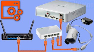
Здесь подробная фото и видео инструкция о порядке подключения и настройки сетевого видео регистратора — NVR (Network Video Recorder).
Различают два основных вида ip видеорегистраторов:
— С поддержкой технологии PoE (питание и данные к ip камере по одному сетевому кабелю). Преимущество в том, что внутри регистратора находиться PoE коммутатор, так соединив одним сетевым кабелем ip камеру Hikvision с регистатором, последний по технологии Plug & Play активирует камеру подаст на неё питание и через пол минуты появиться картинка с камеры, что освобождает от необходимости настраивать подключение вручную.
— Без POE подключение камер к регистратору происходит через коммутатор, а так же необходимо отдельно подать питание к камерам
Подключение видеорегистратора Hikvision
1 Способ построения системы с видеорегистратором с технологией РоЕ.
— Сетевым кабелем подключаем регистратор к роутеру.
— Сетевым кабелем подключаем ip камеру к регистратору в свободный РоЕ порт.
— Питание и данные к ip камере подаются по одному сетевому кабелю.
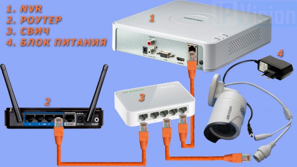
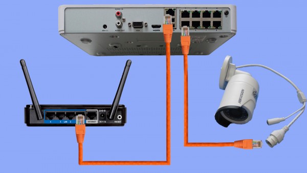
2 Способ построения системы с видеорегистратором без технологии РоЕ.
Подаем питание к ip камере 12 В, соединяем камеру сетевым кабелем с коммутатором, к нему же подключаем видеорегистратор
Соединяем всю систему с роутером по сетевому кабелю
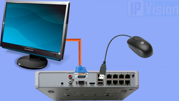
3 Способ построения системы с видеорегистратором и монитором.
Видео регистратор являеться простым компьютером на базе ОС Linux.
Так, подключив напрямую кабелем VGA или HDMI монитор к регистратору, — можно осуществлять управление устройством мышкой, которая идет в комплекте поставки.
Первое включение видеорегистратора Hikvision
При первом включении видеорегистратора услышите повторяющийся звуковой сигнал предупреждающий об ошибке жесткого диска. Если жесткий диск уже вставлен, то отфарматируйте его в настройках регистратора. Если жесткий диск отсутствует в регистраторе, то можно принудительно отключить предупреждающий сигнал в настройках
Как отключить предупреждающий сигнал в видеорегистраторе Hikvision смотрите на видео ниже
Настройка видеорегистратора Hikvision
Ниже подробная видеоинструкция как:
— подключить жесткий диск к видеорегистратору
— активировать видеорегистратор Hikvision
— настроить видеорегистратор через web интерфейс
— добавление видеорегистратора к облачному сервису Hik-connect для просмотра через интернет
Как добавить ip камеру к видеорегистратору Hikvision без РОЕ
Видеоинструкция как активировать и добавить ip камеру к регистратору без текнологии РоЕ, при подключеном мониторе
Вместе с тем, вы всегда можете заказать у нас настроенный и готовый к установке комплект видеонаблюдения
Здесь — Готовые комплекты видеонаблюдения
|
|
|
Если остались вопросы, задавайте в комментариях ниже. Не забывайте указывайть модель устройства в вопросе.
![]() Видеорегистраторы HIKVISION — инструкции по установке, эксплуатации, программированию и обслуживанию, руководства пользователя. Общее количество материалов — 55.
Видеорегистраторы HIKVISION — инструкции по установке, эксплуатации, программированию и обслуживанию, руководства пользователя. Общее количество материалов — 55.
HIKVISION DS- 7008HI-S — Инструкция по эксплуатации
Видеорегистратор
Формат: pdf | Размер: 3.5 Mb | Язык: Русский
HIKVISION DS- 7016HI-S — Инструкция по эксплуатации
Видеорегистратор
Формат: pdf | Размер: 3.5 Mb | Язык: Русский
HIKVISION DS-7004HI-S — Инструкция по эксплуатации
Видеорегистратор
Формат: pdf | Размер: 3.5 Mb | Язык: Русский
HIKVISION DS-7204HFI-SH — Инструкция по эксплуатации
Видеорегистратор
Формат: pdf | Размер: 3.3 Mb | Язык: Русский
HIKVISION DS-7204HI-VS — Инструкция по эксплуатации
Видеорегистратор
Формат: pdf | Размер: 1.3 Mb | Язык: Русский
HIKVISION DS-7204HVI-SH — Инструкция по эксплуатации
Видеорегистратор
Формат: pdf | Размер: 3.3 Mb | Язык: Русский
HIKVISION DS-7204HVI-ST — Инструкция по эксплуатации
Видеорегистратор
Формат: pdf | Размер: 5.6 Mb | Язык: Русский
HIKVISION DS-7204HVI-ST/RW — Инструкция по эксплуатации
Видеорегистратор
Формат: pdf | Размер: 5.6 Mb | Язык: Русский
HIKVISION DS-7208HFI-SH — Инструкция по эксплуатации
Видеорегистратор
Формат: pdf | Размер: 3.3 Mb | Язык: Русский
HIKVISION DS-7208HVI-S — Инструкция по эксплуатации
Видеорегистратор
Формат: pdf | Размер: 1.9 Mb | Язык: Русский
HIKVISION DS-7208HVI-SH — Инструкция по эксплуатации
Видеорегистратор
Формат: pdf | Размер: 3.3 Mb | Язык: Русский
HIKVISION DS-7208HVI-ST — Инструкция по эксплуатации
Видеорегистратор
Формат: pdf | Размер: 5.6 Mb | Язык: Русский
HIKVISION DS-7208HVI-ST/RW — Инструкция по эксплуатации
Видеорегистратор
Формат: pdf | Размер: 5.6 Mb | Язык: Русский
HIKVISION DS-7216HFI-SH — Инструкция по эксплуатации
Видеорегистратор
Формат: pdf | Размер: 3.3 Mb | Язык: Русский
HIKVISION DS-7216HVI-S — Инструкция по эксплуатации
Видеорегистратор
Формат: pdf | Размер: 1.9 Mb | Язык: Русский
HIKVISION DS-7216HVI-SH — Инструкция по эксплуатации
Видеорегистратор
Формат: pdf | Размер: 3.3 Mb | Язык: Русский
HIKVISION DS-7216HVI-ST — Инструкция по эксплуатации
Видеорегистратор
Формат: pdf | Размер: 5.6 Mb | Язык: Русский
HIKVISION DS-7216HVI-ST/L — Инструкция по эксплуатации
Видеорегистратор
Формат: pdf | Размер: 5.6 Mb | Язык: Русский
HIKVISION DS-7216HVI-ST/RW — Инструкция по эксплуатации
Видеорегистратор
Формат: pdf | Размер: 5.6 Mb | Язык: Русский
HIKVISION DS-7304HFI-S — Инструкция по эксплуатации
Видеорегистратор
Формат: pdf | Размер: 4 Mb | Язык: Русский