Модели:
CPD10, CPD15, CPD18, CPD20, CPD25, CPD30, CPD35
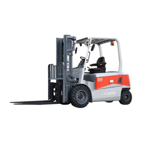
Аннотация к Инструкция по эксплуатации и обслуживанию вилочных электропогрузчиков GROS грузоподъемностью 1.0-3.5 т. Производитель: HELI, Китай
Настоящая инструкция распространяется на вилочные электропогрузчики GROS моделей:
- CPD10-CA1, CPD10-CA2,
- CPD15-CA1, CPD15-CA2, CPD15-CC1, CPD15-CC2,
- CPD18-CA1, CPD18-CA2, CPD18-CC1, CPD18-CC2,
- CPD20-CA1, CPD20-CA2,
- CPD25-CA1, CPD25-CA2,
- CPD30-CC1, CPD30-CC2,
- CPD35-CC1, CPD35-CC2.
Инструкция содержит в себе информацию:
- Правила безопасности при работе и ежедневном текущем ремонте вилочного погрузчика
- Основные параметры вилочного погрузчика
- Конструкция, принципы работы, регулировка и текущий ремонт вилочного погрузчика
- Срок службы и условия хранения
- Перечень критических отказов
- Перечень предельных состояний.
Язык издания: русский.
Дата публикации: 14.10.2022
-
Contents
-
Table of Contents
-
Troubleshooting
-
Bookmarks
Quick Links
Related Manuals for HELI G3 Series
Summary of Contents for HELI G3 Series
-
Page 2
Foreword This manual briefly introduces the technical parameters of our G3 series 4-5 ton lithium battery counterbalanced forklift truck including the structure, working principle and maintenance of the main parts. It can help operators to use this series of forklift trucks reasonably and make the forklift truck play the most effective role. -
Page 3
CONTENTS I. Main specifications of forklift trucks …………….. 1 1. External view of the truck ………………1 2. Main parameters………………….2 3. Size and weight of the main parts that can be disassembled ……..3 II. Construction, Principle, Adjustment and Maintenance of Forklift Trucks ……. 4 1. -
Page 4
I. Main specifications of forklift trucks 1. External view of the truck… -
Page 5
2. Main parameters Item Unit CPD40 CPD45 CPD50 With fork 3990 3990 3990 Overall length Without fork 2920 2920 2920 Front wheel 1350 1350 1500 Overall width Frame 1346 1346 1468 Mast, lowered 2240 2240 2230 Overall height Overhead guard 2275 2275 2270… -
Page 6
3. Size and weight of the main parts that can be disassembled Dimension Model Parts name Unit and weight CPD40 CPD45 CPD50 Max. 1625× 1274× 1511 Overhead dimension guard Weight 132.3 Max. 540×1334×2250 Mast dimension M300 Weight 1015 Max. φ350×1326 dimension Drive axle Weight… -
Page 7
II. Construction, Principle, Adjustment and Maintenance of Forklift Trucks 1. Transmission system 1.1 General description The 5t domestic integrated electrical bridge mainly consists of two reduction box assemblies, a fully enclosed AC motor and a set of brake assemblies. The reduction box assembly contains a planetary reduction mechanism to increase the output torque of the bridge assembly. -
Page 8
1.2.1 Disassembly and assembly of right reduction box assembly Lift and erect the integrated bridge assembly, remove the connection bolts of the reduction box assembly, specification: 14-M12*1.25. When installed, the bolt torque is 124-165N.m. Remove the reduction box assembly and the primary planetary reduction assembly. -
Page 9
Remove the end cover bolt of the reduction box assembly, remove the hub end cover, O-ring seal and hub retainer ring in turn; Then remove the retainer ring, secondary reduction assembly, gear ring cylindrical pin and gear ring from the other side in turn, and the disassembly complete. -
Page 10
friction plate (large), baffle, spacer, friction plate (small), cylinder pin, baffle (spline), compression spring, etc. in turn. 1.2.3 Disassembly of piston assembly Remove the piston bolt, bolt head specification M17, remove the compression spring, then remove the piston. Torque for piston bolt installation is 22-30N.m. -
Page 11
1.2.4 Brake lever, fork disassembly After removing the retainer ring, remove the handle and torsion spring in turn, loosen the bolt, remove the flange and brake fork. 1.3 Announcements in daily maintenance 1)Replace the brake pull lock or adjust the brake structure When the hand brake pull lock is released completely, the wheel is suspended and the wheel hub of the disk-rotating drive axle can make it rotate freely. -
Page 12
2)Fuel quantity of Integrated electrical bridge Model: HELI dedicated 85w/90 Brake side: 1.6-1.7L No brake side: 1-1.1L Every 10-15 days, it is necessary to check the integrated electrical bridge for no oil leakage, if necessary to find out the cause, and timely fill oil. -
Page 13
2. Brake system 2.1 General description The brake system includes service brake and parking brake. Full hydraulic braking mode is adopted for driving brake, and the power source for brake is hydraulic gear pump. The service brake system is mainly composed of brake pedal, brake pump, brake valve and oil-cooled disc brake. -
Page 14
2.1.1 Brake pedal The installation of brake pedal is suspension type. Specific structure is shown in Figure 2-2. The force acting on the pedal is converted to the brake oil pressure by the push rod of the brake valve, and the wet disc brake of the driving axle is acted on to realize braking. 2.1.2 Brake valve The shape of the brake valve and the position of each interface are shown in Fig. -
Page 15
Figure 2-4 (2)The connection of parking brake The parking brake push rod on the driving axle is connected with one end of the brake rod through the brake cable, and the parking brake is realized by changing the working state of the brake push rod. -
Page 16
2) Repeatedly press down the brake pedal, so that the hydraulic pressure can discharge the mixed gas in the brake system. 3) When the air is exhausted and the exhaust plug ejects completely hydraulic oil, press the brake pedal and tighten the gas exhaust plug, and the pre-tightening torque should reach 10N m. -
Page 17
3. Steering system 3.1 General description The steering control mechanism of G3 series 4-5t forklift trucks is mainly composed of steering wheel, pipe column, coupling shaft, steering unit and installation bracket (as shown in Figure 3-1). They are fixed on the panel of instrument bracket by installation bracket. The steering wheel, pipe column and coupling shaft are connected together. -
Page 18
Figure 3-1 Steering operation device 3.1.1 Steering wheel and its function The steering wheel is the most direct component for the driver to control the driving direction of forklift truck. During the normal driving process of forklift truck, the driver turns the steering wheel to the left or right, so that the forklift truck can drive to the left or right. -
Page 19
maintain his body balance. During these operations, the speed of forklift driving and steering should not be too high to avoid accidents There is a horn in the center of the steering wheel. When the driver wants to prompt the pedestrians, he can use his hand to press down the cover of the box marked with horn. -
Page 20
Figure 3-3 Principle diagram of the hydraulic steering system 3.1.4 Full hydraulic steering unit Full hydraulic steering gear (Figure 3-4) transmits pressure hydraulic oil to the steering cylinder according to the rotation angle of steering wheel. The hydraulic oil drives the piston rod of the steering cylinder to move left and right, and realizes steering through the steering mechanism. -
Page 21
steering system will automatically overflow in order to protect the components of the system from damage, so as to realize self-protection. The output pressure of the steering gear has been adjusted according to different models before leaving the factory. The user can not adjust it by himself to avoid damaging the hydraulic components. -
Page 22
is supported by thrust gaskets on the inner side of the steering upper and lower axle plates. The thrust gaskets are also self-lubricating as the axle sleeves. The connection between the main pin and the steering knuckle assembly is achieved by tightening the screw, and the main pin and the steering knuckle assembly are relatively fixed. -
Page 23
1.hub cover 21.washer 16 2.hub 22.support seat of steering axle 3.hub bolt 23.sleeve 4.hub nut 24.shim 5.left steering knuckle 25.end cover 6.link rod 26.sleeve 7.straight through type grease nipple 27.V type seal ring 8.steering cylinder assembly 28.washer 9.steering axle assembly 29.thrust washer 10.baffle 30.main pin… -
Page 24
piston rod is realized by O-ring, and the seal between piston and cylinder inner wall is realized by lattice ring. The cylinder head and cylinder are connected by threads. There are two supporting rings in the cylinder head. The dust-proof seal between the cylinder head and the piston rod adopts the El seal ring. -
Page 25
Figure 3-7 Connection between steering knuckle and axle 3.1.8 Hub The hub is used to connect the steering wheel with the steering knuckle assembly. There are two tapered roller bearings in the hub. The inner ring is mounted on the steering knuckle body, the outer ring is mounted in the hub, and there is grease in the hub. -
Page 26
(5) When the torque is higher than the prescribed value, retreat the round nut close to the end face of the bearing by 1/24-1/12 turn, and then measure the hub’s torque until the hub’s rotational torque reaches the prescribed value. Similarly, when the torque is lower than the prescribed value, retreat the round nut close to the bearing by 1/24-1/12 turn, and then measure the hub’s torque. -
Page 27
3.2.3 Steering system troubleshooting Problem Analyses of trouble Remedies Fail to turn Pump damaged or breaking down. Replace hand-wheel Hose or joint damaged or pipeline blocked. Clean or replace The pressure of the safety valve is too low. Adjust the pressure Air in steering oil circuit. -
Page 28
Note The manufacturer reserves the right to continuous improvement of the product. If there is any discrepancy between the physical object and the instructions, please consult the manufacturer. The principle diagram of the electrical system is shown in Fig. 4-1 and Fig. -
Page 29
Figure 4-1 Principle diagram of electric system(CPD40~50-GB3Li)… -
Page 30
Figure 4-2 Principle diagram of electric system(CPD40~50-GB2Li)… -
Page 31
4.2 Instrument 4.2.1 Jiachen color screen instrument 4.2.1.1 General description (1) It is a color screen instrument connected to the vehicle system by CAN bus. The color screen instrument can display the running state of the vehicle and has diagnostic function. -
Page 32
4.2.1.3 Display interface Fig. 4-4 Instrument interface display information introduction Fig. 4-5 Instrument interface-fault display 4.2.1.4 Functions and applications (1) Hour meter The number shows the cumulative working time of the current truck. The key switch is connected to the power supply. After the truck starts to work, the working timer starts to count. -
Page 33
Display the current battery electric quantity. The current electric quantity is displayed at the top of the battery icon. (4) Travelling mode Display the current working mode, there are «P», «E», «S» three levels. (5) Steering wheel Angle indicator Represents the direction of the steering wheel. (6) Steering angle indicator The arrow represents the direction of the steering wheel. -
Page 34
to the CAN bus network. Its node definition is shown in the following table: CAN bus network related figures Module Traction main CPU2.0: Traction main CPU2.1 Traction controller Pump main CPU5.0: Pump main CPU5.1 Pump controller Independent steering CPU13.0: Independent steering Steering controller CPU13.1 Instrument 16.0: Instrument 16.1… -
Page 35
Fig. 4-8 Instrument interface — fault display 4.2.2.4 Functions and applications (1) Milemeter The number shows the total mileage of the current truck. (2) Battery status Display the current battery power icon, the top of the battery icon shows the current power value. -
Page 36
When parking brake switch is closed, parking brake indicator light is on; Seat belt light, reserved function, this LED light is temporarily not in use. 4.3 Control system 4.3.1 Introduction to Control System This series of balanced weight forklift adopts Swedish INMOTION AC motor controller or Italian ZAPI AC motor controller, controller is a three-phase AC asynchronous motor inverter, which controls traction motor, pump motor and steering motor. -
Page 37
Figure 4-9 Assembly of control device(CPD40~50-GB3Li) Model of traction controller:Inmotion ACS80XL-550C-35P 80V/550A Model of pump controller: Inmotion ACS80L-440C-35P 80V/440A Model of steering controller:Inmotion ACS80S-220C-35P 80V/220A 4.3.3 ZAPI Control system composition Figure 4-10 Assembly of control device(CPD40~50-GB2Li) Model of traction controller: ZAPI ACE3(80V/550A) Model of pump controller: ZAPI ACE3(80V/450A)… -
Page 38
◆ Test the truck with four wheels raised (off the ground) after the controller being fixed, in that case there will be no danger even the connection is in error. ◆ A certain amount of voltage will remain in filter capacitance after the turn off of the electric switch. -
Page 39
4.5.2 Lithium battery usage The usage and routine maintenance of the lithium battery will influent lithium battery life and performance. So the operator should maintain the lithium battery according to the manual and actual conditions. 4.5.3 Lithium battery maintenance (1) Please ensure that specified lithium charging device is used for charging, and the charging current should not exceed 2C;… -
Page 40
4.5.5 Lithium battery error and resolution The cause that made the Lithium battery error is various, except the effect of the quality manufacture and transport storage, mostly due to the improper maintenance. Find out the faults and analyze the causation as soon as possible to exclude. 4.5.6 Daily maintenance (1) Check the wear status on the contact point;… -
Page 41
4.6 Diagnosis 4.6.1 General instruction The traction control system, loading control system, steering control system and color screen instrument system assembled in the truck are continually monitoring micro-processor controller. They all have a diagnosis program to a main function. The program includes the following point: (1) Diagnosis when the key switch being off: the circuit of the watching dog, current censor, charging of the capacity, phase voltage, driving of the connector, CAN-bus connector,… -
Page 42
2)Fault of harness; fault of accelerator signal CAN error Check if the controller and CAN bus has fault. Battery low voltage Charge the battery Pump speed 1 switch active at Reset the tilting switch key on Pump speed 2 switch active at Reset the tilting switch key on Pump speed 3 switch active at… -
Page 43
relay. ) average execution time out of Restart the key. range Short circuit Check the harness of power and motor. The temperature of traction driver is over high and it ACS temp high needs to be cooled down. 1)The temperature of traction motor is over high and it needs to be cooled down;… -
Page 44
1)Over high temperature of motor Motor temp high 2)Fault of motor temperature sensor or harness Check if there is short circuit of pump motor and Over Current Error cable. 1)Change pre-charging resistance. Charging error 2)Low battery voltage 3)Fault of harness 1)Check battery voltage;… -
Page 45
voltage. Check battery parameters. 1)Check battery voltage; DC bus low 2)Check battery voltage; 3)Check if main contactor is connected. 1)Restart the key; Internal supply error 2)Check the load and harness of controller at 5V and 12V port. BMS temperature protection Check the lithium battery temperature BMS temperature high Check the lithium battery temperature… -
Page 46
FAILURE Fault in the hardware section of the logic board which deals with voltage feedbacks of motor phases. Troubleshooting The failure lies in the controller hardware. Replace the controller. Cause This fault is displayed when the controller detects an undervoltage condition at the key input . -
Page 47
Troubleshooting: — Motor internal connections — If motor windings/cables have leakages towards truck frame — If no problem are found on the motors, the problem is inside the controller, it is necessary to replace the logic board. Cause 1 Start-up test. Before switching the LC on, the software checks the power bridge: it turns on alternatively the high-side power MOSFETs and expects the phase voltages increase toward the positive rail value. -
Page 48
replace the LC. Cause The LC coil is driven by the controller, but it seems that the power contacts do not close. In order to detect this condition the controller injects a DC current into the CONTAC motor and checks the voltage on power capacitor. If the power capacitors get discharged it means that the main contactor is open. -
Page 49
Troubleshooting: It is necessary to improve the controller cooling. To realize an adequate cooling in case of finned heat sink important factors are the air flux and the cooling-air temperature. If the thermal dissipation is realized by applying the controller base plate onto the truck frame, the important factors are the thickness of the frame and the planarity and roughness of its surface. -
Page 50
procedure. Troubleshooting: — Check the wirings. Check the mechanical calibration and the functionality of the accelerator potentiometer. Acquire the maximum and minimum potentiometer value through the PROGRAM VACC function. — If the problem is not solved, replace the logic board. Cause: Incorrect starting sequence. -
Page 51
Cause: Lithium battery alarm ; Current cut-out protection . when this alarm appears , the truck should stop to work , inhibit traction and lifting and tilt ,only steering function can work as normal BMS10 Troubleshooting:Check the lithium battery,ask for help to the lithium battery manufacturer Cause:… -
Page 52
manufacturer Cause: Lithium battery alarm ; The cell of battery over-discharge .when this alarm appears , the truck should stop work , inhibit traction and lifting and tilt ,only BMS2 steering function can work as normal Troubleshooting:Check the lithium battery,ask for help to the lithium battery manufacturer Cause:… -
Page 53
Cause: Networking alarm ; the traction inverter received the 1AA message from the networking device,if the inverter lost this message,this alarm will appears, the truck should inhibit lifting and traction function , but tilt , side shift , attachment , 0X1AA TIMEOU steering function can work as norma… -
Page 54
implemented in this truck Cause This alarm occurs only when the controller is configured to drive a PMSM and the feedback sensor selected in the HARDWARE SETTINGS list is ENCODER ABI + PWM. The controller does not detect correct information on PWM input at start-up ACQ. -
Page 55
Troubleshooting: — Check the wirings. — If the motor direction is correct, swap A and B signals. — If the motor direction is not correct, swap two of the motor cables. — If the problem is not solved, contact a Zapi technician Cause: WRONG The inverter key voltage is wrong . -
Page 56
STOP analog, see paragraph 7.2.3). Troubleshooting: — Check the temperature read by the thermal sensor inside the motor through the MOTOR TEMPERATURE reading in the TESTER function. — Check the sensor ohmic value and the sensor wiring. — If the sensor is OK, improve the cooling of the motor. — If the warning is present when the motor is cool, replace the controller. -
Page 57
Troubleshooting — Check if there is a short circuit or a low-impedance conduction path between the negative of the coil and -B. — Collect information about: o the voltage applied across the EVP2 coil, o the current in the coil, o features of the coil. -
Page 58
Cause: The minimum voltage of the lift potentiometer is not correctly set. PUMP VACC Troubleshooting: NOT OK It is suggested to repeat the acquiring procedure of MIN LIFT and MAX LIFT (see paragraph 9.2). Cause: Man-presence switch is not enabled at pump request. Troubleshooting: PUMP — Check wirings. -
Page 59
Troubleshooting: — Verify that the EB coil is connected correctly . — Verify that the parameter POSITIVE E.B.is set in accordance with the actual configuration . The software, in fact, depending on specific parameter value, makes a proper diagnosis; a wrong configuration of this parameter could generate a false fault. -
Page 60
Troubleshooting — Verify the motor phases connection on the motor side — Verify the motor phases connection on the inverter side — Check the motor power cables. — Replace the controller. — If the alarm does not disappear, the problem is in the motor. Replace it. Cause: WRONG Wrong software version on supervisor uC. -
Page 61
Cause: At start-up, the hardware circuit dedicated to enable and disable the MC driver is found to be faulty. The hexadecimal value “XX” facilitates FAULT Zapi technicians debugging the problem Troubleshooting: This type of fault is not related to external components. Replace the logic board. Cause: The CPOT BRAKE input read by the microcontroller is at its maximum value BRAKE… -
Page 62
Troubleshooting: Execute a CLEAR EEPROM procedure (refer to the Console manual). Switch the key off and on to check the result. If the alarm occurs permanently, it is necessary to replace the controller. If the alarm disappears, the previously stored parameters will be replaced by the default parameters. -
Page 63
which has to be replaced. Cause: No load is connected between the NEVP output and the electrovalve positive terminal. COIL Troubleshooting: OPEN — Check the EVP condition. — Check the EVP wiring. — If the problem is not solved, replace the logic board. Cause — The EVP driver is shorted . -
Page 64
Cause The logic board measures a key voltage that is constantly out of range, below the VKEY minimum allowed value. Troubleshooting SHORTE — Check that the battery has the same nominal voltage of the inverter. — Check the battery voltage, if it is out of range replace the battery. — In case the problem is not solved, replace the logic board. -
Page 65
paragraph 9.1). The acquired values MIN VACC and MAX VACC are inconsistent. Troubleshooting: Acquire the maximum and minimum potentiometer values through the PROGRAM VACC function. If the alarm is still present, check the mechanical calibration and the functionality of the accelerator potentiometer. If the problem is not solved, replace the logic board. -
Page 66
SHORTE Troubleshooting — Check that motor phases are correctly connected. — Check that there is no dispersion to ground for every motor phases. — In case the problem is not solved, replace the controller. Cause: One or more on/off valve drivers are shorted. DRV. -
Page 67
Cause: The EVP driver is not able to drive the EVP coil. The device itself or its driving circuit is damaged. DRIVER OPEN Troubleshooting: This fault is not related to external components. Replace the logic board. Cause: This alarm occurs when there is an overload of one or more EV driver. As soon as the overload condition has been removed, the alarm disappears by releasing and then enabling a travel demand. -
Page 68
TION Troubleshooting: The alarm ends when the acquisition is done. Cause: This is a safety related test. It is a self-diagnosis test that checks the communication between master and supervisor microcontrollers. NO CAN MSG. Troubleshooting: This alarm could be caused by a CAN bus malfunctioning, which blinds master- supervisor communication Cause: CHECK… -
Page 69
Troubleshooting: — Check if there is a short or a low impedance path between the negative coil terminal and -BATT. — Check if the voltage applied is in accordance with the parameters set . — If the problem is not solved, replace the controller. Table 4-5 Fault list of auxiliary pump, auxiliary traction ACE3 traction slave alarms (node 2.1)and ACE3 pump slave alarms (node ALARM… -
Page 70
Cause: The voltage read by the microcontroller at the steering-sensor input is not within the STEER RIGHT VOLT ÷ STEER LEFT VOLT range, programmed through STEER the STEER ACQUIRING function . SENSOR Troubleshooting: Acquire the maximum and minimum values coming from the steering potentiometer through the STEER ACQUIRING function. -
Page 71
Cause: The algorithm implemented to check the main RAM registers finds wrong WRONG contents: the register is “dirty”. This alarm inhibits the machine operations. Troubleshooting MEM. Try to switch the key off and then on again, if the alarm is still present replace the logic board. -
Page 72
Cause: This alarm occurs when the A/D conversion of the analog inputs returns frozen values, on all the converted signals, for more than 400 ms. The goal of this ANALOG diagnosis is to detect a failure in the A/D converter or a problem in the code flow INPUT that skips the refresh of the analog signal conversion. -
Page 73
Table 4-6 Fault list of steering pump main CPU ACE0 independent steering pump master alarms (node 13.0) CODE ALARM NAME Cause: This is a safety related test. It is a self-diagnosis test that involves the logic between master and supervisor microcontrollers WATCHDOG Troubleshooting: This alarm could be caused by a CAN bus malfunctioning, which blinds… -
Page 74
the motor voltage feedback tested; if it is lower than expected value (a range of values is considered), the controller enters in fault state. Troubleshooting — If the problem occurs at start up (the LC does not close at all), check: o motor internal connections (ohmic continuity);… -
Page 75
power capacitors get discharged it means that the main contactor is open. Troubleshooting — LC contacts are not working. Replace the LC. — If LC contacts are working correctly, contact a Zapi technician. Cause In standby, the sensor detects a current value different from zero. STBY I HIGH Troubleshooting The current sensor or the current feedback circuit is damaged. -
Page 76
Troubleshooting: Check the temperature read by the thermal sensor inside the motor through the MOTOR TEMPERATURE reading in the TESTER function. — Check the sensor ohmic value and the sensor wiring. — If the sensor is OK, improve the cooling of the motor. — If the warning is present when the motor is cool, replace the controller. -
Page 77
Troubleshooting: — Check wirings. — Check microswitches for failures. — Through the TESTER function, check the state of the inputs are coherent with microswitches states. — If the problem is not solved, replace the logic board. Cause: This alarm occurs when both the travel requests (FW and BW) are active at the same time. -
Page 78
Cause: Controller is acquiring data from the absolute feedback sensor. ACQUIRING A.S. Troubleshooting: The alarm ends when the acquisition is done. Cause This alarm occurs if the absolute position sensor is used also for speed estimation. If signaled, it means that the controller measured that the engine was moving too quick. -
Page 79
Cause The motor current has overcome the limit fixed by hardware. Troubleshooting OVERLOAD Reset the alarm by switching key off and on again. If the alarm condition occurs again, ask for assistance to a Zapi technician. The fault condition could be affected by wrong adjustments of motor parameters. Cause: Mismatch between “ENCODER PULSES 1”… -
Page 80
Troubleshooting: — Check that LIFT and LOWER requests are not active at the same time. — Check the LIFT and LOWER input states through the TESTER function. — Check the wirings. — Check if there are failures in the microswitches. — If the problem is not solved, replace the logic board. -
Page 81
Troubleshooting: If the EVP TYPE parameter is set to ANALOG (See paragraph 8.1.1), please acquire again the values of MIN LOWER and MAX LOWER. If the controller is in configuration COMBI and lifting is proportional, please acquire again also the values of MIN LIFT and MAX LIFT. Cause: There is a hardware problem in the smart driver circuit . -
Page 82
Cause Short circuit between two motor phases. The number that follows the alarm identifies where the short circuit is located: — 36 à U – V short circuit — 37 à U – W short circuit — 38 à V – W short circuit MOT.PHASE SH. -
Page 83
capacitors: — High voltage à Overvoltage condition — Low/normal voltage à Undervoltage condition Troubleshooting If the alarm happens during the brake release, check the line contactor contact and the battery power-cable connection. Cause: At start-up, the hardware circuit dedicated to enable and disable the MC driver is found to be faulty. -
Page 84
Troubleshooting — Check the motor power cables. — Check the impedance between U, V and W terminals and -Batt terminal of the controller. — Check the motor leakage to truck frame. — If the motor connections are OK and there are no external low impedance paths, the problem is inside the controller. -
Page 85
motor parameters. Cause The voltage feedback of LC driver (A16) is different from expected, i.e. it is not in accordance with the driver operation. Troubleshooting — Verify LC coil is properly connected. POSITIVE LC — Verify CONF. POSITIVE LC parameter is set in accordance with the OPEN actual coil positive supply (see paragraph 7.2.5). -
Page 86
OUT function is active (POSITIVE EB = 1 or 2). Troubleshooting: Check connector B1: it must be connected to the battery voltage (after the main contactor). Cause: The output of the motor thermal sensor is out of range. Troubleshooting: SENS MOT — Check if the resistance of the sensor is what expected measuring its TEMP KO resistance. -
Page 87
— In case no failures/problems have been found, the problem is in the controller, which has to be replaced. Cause This alarm occurs when an overload of the MC driver occurs. Troubleshooting — Check the connections between the controller outputs and the loads. COIL SHOR. -
Page 88
Cause This fault appears when no load is connected between the NLC output and the positive voltage (for example +KEY). Troubleshooting LC COIL OPEN — Check the wiring, in order to verify if LC coil is connected to the right connector pin and if it is not interrupted. -
Page 89
Troubleshooting If the problem occurs permanently it is necessary to replace the logic board. Cause: At start-up, the hardware circuit dedicated to enable and disable the EV drivers is found to be faulty. The hexadecimal value “XX” facilitates Zapi technicians debugging the problem. HW FAULT EV. -
Page 90
Cause: Warning on supervisor uC. WARNING SLAVE Troubleshooting: Connect the Console to the supervisor uC and check which alarm is present. Cause The error between the Iq (q-axis current) setpoint and the estimated Iq is out of range. MISMATCHED Troubleshooting Ask for assistance to a Zapi technician in order to do the correct adjustment of the motor parameters. -
Page 91
according to the value read by the voltmeter. — Replace the battery. Cause: At start-up the amplifiers used to measure the motor voltage sense voltages above 3 V or below 2 V. WRONG ZERO Troubleshooting: This type of fault is not related to external components. Replace the logic board. -
Page 92
Troubleshooting: Acquire the maximum and minimum values from the steering potentiometer through the STEER ACQUIRING function. Check the mechanical calibration and the functionality of the potentiometer. — If the problem is not solved, replace the logic board. Cause Mismatch between “ENCODER PULSES 1” parameter and “ENCODER WRONG ENC PULSES 2”… -
Page 93
Troubleshooting Try to switch the key off and then on again, if the alarm is still present replace the logic board. Cause: Supervisor microcontroller has detected that the master microcontroller has imposed a wrong setpoint for TG or EB output W.SET. -
Page 94
code flow that skips the refresh of the analog signal conversion. Troubleshooting If the problem occurs permanently it is necessary to replace the logic board. Cause: The software is not compatible with the hardware. Each controller produced is “signed” at the end of line test with a specific code mark saved in EEPROM according to the customized Part Number. -
Page 95
5. Hydraulic system The truck adopts load-sensitive hydraulic system (as shown in the figure), which mainly consists of working oil pump, multi-way valve, lifting cylinder, tilting cylinder and pipeline. The working oil pump is driven by motor, and the hydraulic oil is distributed to working cylinder by multi-way valve through gear oil pump. -
Page 96
The multi-way valve is a piecewise multi-way valve. The hydraulic oil from the working oil pump is controlled by a multi-way valve lever, which distributes the high pressure oil to the lifting or tilting cylinder and returns the oil to the tank. The shape of the multi-way valve is shown in the following figure. -
Page 97
Figure 5-3 Oil inlet piece of multi-way control valve Figure 5-4 Lifting and lowering piece of multi-way control valve Figure 5-5 Tilting piece of multi-way control valve Figure 5-6 Auxiliary piece of multi-way control valve… -
Page 98
Figure 5-7 Stroke switch built at the end of the covers of tilting piece and auxiliary piece 6. Lifting system Table 6-1 Main parameters Item Content Mast type Rolling type, weld mast with free lift, two-stage telescopic type Cross section of inner mast Cross section of outer mast Max. -
Page 99
6.1 General description The lifting system is of the two-stage roller type with vertical up and down. It consists of the inner mast, the outer mast, two rear lifting cylinder, fork carrier, backrest and fork. 6.2 Inner and outer mast The inner and outer portal frames are welded parts, and the whole mast is mounted on the frame by supporting axle. -
Page 100
through the tilting cylinder. Under the action of the tilting cylinder, it can tilt forward and backward, with a forward tilt of 6 degrees and a backward tilt of 8 degrees. The channel of outer mast is C type, and one pair of rollers is installed in its upper end; the channel of inner mast is H type, and its lower part is installed with a pair of rollers. -
Page 101
Readjust the stroke of the lift cylinder when the lift cylinder, the inner mast or the outer mast is replaced. As following: (1) Place piston rod heads into the upper beam of the inner mast without shims. (2) Slowly lift the mast to the maximum stroke of the cylinder, check whether the two cylinders are synchronized. -
Page 102
(3) Lift the fork to the highest point and confirm that the clearance B between the fork carrier’s limit block and the inner mast’s limit block is 5-10 mm. (4) Make the fork carrier fall to the ground and tilt back in place, adjust the adjusting nut of the upper end joint of the chain, so that the tension of the two chains is the same. -
Page 103
(4) Take apart bolts which fastened lift cylinders and the inner mast. Hang up the inner mast without losing shims of the piston rod heads carefully. (5) Take apart bolts which jointed lift cylinders and the bottom of outer mast and take apart the oil-pipe between two lift cylinders without loosing the nipple. -
Page 104
III. Lithium battery changing 1. General description Lithium battery is the energy source of the truck. When the working intensity is high and the operation duration is long, the lithium battery needs to be replaced. The lithium battery can be changed from the right side of the truck body by forklift, electric pallet truck, pallet stacker and other tools. -
Page 105
H3 series 2.5 t electric forklift truck can be picked up by another H3 series 2.5 t electric forklift truck. It is known that the fork length L4 of the 2.5 t electric forklift truck of Heli H3 series is 1070 mm. The front overhang L2 of the truck is 465 mm, the fork feed L9 is about 720 mm, and the lithium battery weight Q1 of 80V/600Ah is 1185 kg. -
Page 106
(2)Disconnect the lithium battery connections. (3)Loose and remove the lithium battery limit block. (4)Pick up the lithium battery with forklift truck, electric pallet truck or pallet stacker. -
Page 107
(5)Remove the lithium battery from the compartment and place the lithium battery on pre-prepared carrier. Please reserve enough space for fork in and out. (6)Use the crane to separate the lithium battery pack from the bottom counterweight 4. Steps to install the lithium battery Please install the lithium battery according to following steps: (1)Install the lithium battery pack together with the auxiliary counterweight by crane. -
Page 108
(2)Transport the lithium battery pack to the battery warehouse by pallet truck or forklift truck. (3) Put down the lithium battery until the right side of lithium battery coincide with the inner side of lithium battery limit block. (4)Put down lithium battery limit block and adjust the limit screw to the end face of the lithium battery box. -
Page 109
(5)Connect the battery. (6)Close the side door.
Heli Forklift Truck operator’s, workshop, service and repair manuals, spare parts catalogs, error codes in PDF download
|
Title |
File Size |
Download Links |
|
HELI 2-3.5t Counterbalanced type Forklift Operation & Service |
47.3Mb |
Download |
|
HELI CBD15J-Li2, CBD18J-LI2, CBD20J-LI2 Manual [PDF] |
892.5kb |
Download |
|
Heli CPCD 50 / 60 / 70 / 80 / 100 h2000 5-10t. Forklift Technical |
1.7Mb |
Download |
|
Heli CPCD15-CPCD16 Forklift Truck with Engine Service & Operation |
4.7Mb |
Download |
|
Heli CPCD25-KU11 / CPCD30-KU11 Operator’s Manual [PDF] |
9Mb |
Download |
|
Heli CPQD CPCD 40-50 2010 Parts Manual [PDF] |
1.8Mb |
Download |
|
Heli CPQD / CPCD 2-3,5 (2003-2010) Parts Manual [PDF] |
60.9Mb |
Download |
|
HELI CQD16X1, CQD18X1 Electric Narrow Aisle 1.6-1.8t Operation & |
3.3Mb |
Download |
|
HELI CQDH13,14-850 Electric Reach Stacker Operation And Maintenance |
832.5kb |
Download |
|
Heli Error Codes Fault Overhaul Manual [PDF] |
257kb |
Download |
|
HELI FG10-18 Parts Catalog [PDF] |
5.9Mb |
Download |
|
Heli Forklift H2000 5-10t Operation and Service Manual [PDF] |
10.4Mb |
Download |
|
Heli G-Series 1.25t,1.5t Three-wheel Battery Parts Manual |
38.6Mb |
Download |
|
Heli G2 L365-2-2016 1.5t 2t Reach Truck Parts Manual [PDF] |
64.1Mb |
Download |
|
HELI G3-Series Operation & Service Manual [PDF] |
4.8Mb |
Download |
|
Heli h2000 1-1.8t. diesel-petrol engine Parts Manual [PDF] |
38Mb |
Download |
|
Heli h2000 1-3.5t. Parts Manual [PDF] |
2.6Mb |
Download |
|
Heli h2000 2-3t. CPC-CPCD-CPQ-CPQD20 / 25 / 30 Forklift Technical |
2.8Mb |
Download |
|
Heli HJ493 Diesel Engine Parts Manual [PDF] |
19.9Mb |
Download |
|
Heli K-Series Forklift 1-10t Couneterbalanced Maintenance & |
3.9Mb |
Download |
|
Heli K-Series Forklift 2-3.5t Couneterbalanced Operation & |
30.1Mb |
Download |
|
Heli K-Series Forklift 5-10t Operation & Service Manual |
25Mb |
Download |
|
Heli L242-2-2009 18t Parts Manual [PDF] |
41.1Mb |
Download |
|
Heli L272-10-2015 G 3t,3.5t Parts Manual [PDF] |
33.3Mb |
Download |
|
Title |
File Size |
Download Links |
|
CHL 1-1,8 ton engine powered Forklift Technical Specifications |
1.3Mb |
Download |
|
CHL 8-10 ton Engine Powered Forklift Technical Specifications |
346.2kb |
Download |
|
CHL CPQYD 30 Forklift Technical Specifications [PDF] |
1.9Mb |
Download |
|
CHL Forklift 2-3.5t Operation Service Manual [PDF] |
47.3Mb |
Download |
|
CHL G-Series 1-3.5t Forklift Technical Specifications [PDF] |
3.8Mb |
Download |
Anhui Forklift Truck Group, which is territorially located in China, is engaged in the production of forks. Heli is a leader in warehouse equipment at home and is considered one of the world’s
largest manufacturers, along with such famous brands as Toyota, Linde, Komatsu, Jungheinrich, Nissan and others. Currently, a group of companies is very
respected in China, has the highest AAA credit rating, and also owns the largest technical center in the country.
HELI is presented by the CPCD diesel series. This technique is capable of unloading at an altitude of up to 6 meters, as well as work with a weight of 1 to 10 tons.
Equipped with high -quality diesel engines from the ISUZU company, which are released by their reliability, high specific power, as well as low
fuel consumption. As an option, you can install the exhaust gas catalyst, which will increase environmental friendliness and will be especially useful in storage facilities.

Electric carry lifts have smaller sizes and are able to work only with a weight of up to 3 tons. The unloading height is limited to 3300 mm. Due to their characteristics, small sizes and
excellent stability, it is perfect for working with cargoes of relatively small weight.
Loaders are represented by two CPCD series, which have different indices. The S-AQ series has a maximum carrying capacity of up to 1.5 tons, and the rear wheel is spared. Series B and E represent
more powerful models with a carrying capacity of up to 3 tons, but with full -fledged rear wheels. Between themselves, they differ in different capacity of the battery, which leads to different
weights and dimensions.

Набор органов управления зависит от типа вилочного погрузчика. Перед началом эксплуатации конкретной машины важно изучить руководство пользователя, в котором описано расположение, назначение, особенности работы органов контроля. Никогда не садитесь за руль нового погрузчика, предварительно не ознакомившись с инструкцией по эксплуатации.
Виды, назначение органов управления
Для вождения вилочного погрузчика оператор может использовать:
- рулевое колесо;
- рычаги или джойстики, управляющие гидравликой;
- переключатель с замком и ключом зажигания (запуска);
- рычаги переключения направления движения, передач;
- рукоятку или переключатель стояночного тормоза;
- педали тормоза, акселератора, сцепления или точного управления;
- переключатель фонарей, поворотных сигналов.

Для управления гидравлическим грузоподъемником вилочный погрузчик оснащен как минимум рычагами подъема и наклона вил (мачты). Во многих моделях предусмотрен третий рычаг, отвечающий за боковое смещение каретки для перемещения груза в стороны. Иногда установлен также четвертый рычаг, с помощью которого регулируется ширина вил или выполняются функции дополнительного навесного оборудования.

Рычаг переключения направления движения (передач) расположен с правой стороны от оператора или на рулевой колонке. У него обычно три положения: вперед, нейтраль, задний ход.
Что касается педалей, то у автопогрузчиков с механической коробкой передач установлены педали сцепления, тормоза и акселератора.

В вилочных погрузчиках с автоматической трансмиссией педали сцепления нет. Вместо нее может применяться педаль точного управления. Она используется для движения очень медленным ходом в тесном пространстве.
В вилочных погрузчиках с гидростатической трансмиссией за переключение направления хода обычно отвечают две педали акселератора. При нажатии на первую из них происходит движение вперед, а при нажатии на вторую – назад. Степень ускорения регулируются силой нажатия. Торможение происходит при отпускании педали, а сила торможения зависит от быстроты отпускания.

Стояночный тормоз вилочного погрузчика работает аналогично автомобильному. Он активируется с помощью рукоятки или переключателя на панели.
Наиболее продвинутые органы управления встречаются в некоторых дорогих электропогрузчиках и ричтраках. Например, вместо рукояток подъема, наклона и бокового смещения вил может использоваться удобный джойстик или эргономичные кнопки под пальцами оператора.
![]()
Heli H2000 5-10 t Forklift Truck Service Manual PDF
Heli H2000 5-10 t Forklift Truck Service Manual PDF
Heli H2000 5-10 t Forklift Truck Service
Adobe Acrobat Document
10.5 MB
![]()
Heli H2000 4-5 t Forklift Truck Parts Catalog PDF
Heli H2000 4-5 t Forklift Truck Parts Catalog PDF
Heli H2000 4-5 t Forklift Truck Parts Ca
Adobe Acrobat Document
1.9 MB
![]()
Heli H2000 2-3.5 t Forklift Truck Parts Catalog PDF
Heli H2000 2-3.5 t Forklift Truck Parts Catalog PDF
Heli H2000 2-3.5 t Forklift Truck Parts
Adobe Acrobat Document
9.6 MB
Some HELI Forklift Truck Service Manuals & Parts Catalogs PDF with Wiring Diagrams & Error Codes DTC are above the page.
Anhui Heli Forklift Truck is one of the largest in China for the production of lifting equipment. It was founded in 1958, and the first forklifts were launched in February 1963.
In 1976, the company’s factory began manufacturing the first 20-ton and 25-ton models in China. About 9 years later, according to the technology of the company TCM, production of fork lift trucks with a load capacity of 1-10t began.
Today, Anhui Heli is a large city-forming corporation, which includes about ten factories that produce not only loaders, but also components for them, hardware, frames, balances,
and a number of components for other manufacturers of lifting and transport equipment.
Changed and design approach. Now the company does not manufacture products under license, but uses its own developments and components.
The plant is working on quality, updating the technical base; all production processes are standardized to ISO 9001. At the same time, the process of product modernization is in progress. The
latest range of loaders was released in 2000.