- Manuals
- Brands
- point Manuals
- Industrial Equipment
- Vitap
- Instruction manual
-
Contents
-
Table of Contents
-
Bookmarks
Quick Links
INSTRUCTIONS MANUAL
POINT
Vitap
WOODWORKING MACHINES
53036 POGGIBONSI (SIENA) ITALY
VIA PISANA 149 TEL 0577-987511
FAX 0577-981670
WEB www.vitap.it
E-mail vitap@ vitap.it
Rel. 03
Summary of Contents for point Vitap
-
Page 1
INSTRUCTIONS MANUAL POINT Vitap WOODWORKING MACHINES 53036 POGGIBONSI (SIENA) ITALY VIA PISANA 149 TEL 0577-987511 FAX 0577-981670 WEB www.vitap.it E-mail vitap@ vitap.it Rel. 03… -
Page 2
Rel. 03… -
Page 3: Chapter 8.1 Working Cycle
INSTRUCTIONS MANUAL’S Rel. 03 WORKING CYCLE MACHINE SWITCH ON CHAPTER 6.1 CHECK OUT OR CHANGE OF SOFTWARE EQUIPPING CHAPTER 7.1 DRAWING CREATION OR CHANGE CHAPTER 7.3 FAILURES SIGNALLING RESETTING CHAPTER 7.2 OPENING, CREATION, CHANGE AND START JOBLIST CHAPTER 7.3 POSSIBLE FAILURES SIGNALLING CHAPTER 8.1 WORKING CYCLE Rel.
-
Page 4
INDEX CHAPT 1 GENERAL INFORMATIONS CHAPT 7 SOFTWARE 1.1. Introduction 7.1. Drawing creation or change 1.2. General instructions 7.2. Opening, creation, change and start 1.3. Forward of documentation (list of programmes) 7.3. Failures signalling CHAPT 2 TECHNICAL FEATURES 7.4. Software functions 7.5. -
Page 5: General Warnings
CAP. 1 GENERAL INFORMATION 1.1 PREMISE TO THE OPERATIONS MANUAL This instructions manual is aimed at machine operators and above all, at technical staff, whose responsibility is the correct use of the machine as per safety purposes. We therefore recommend that you read it carefully, particularly the paragraphs on warnings and use modes and that you always keep it in its cover, if possible together with the machine in order to…
-
Page 6: Chapter 2 Technical Specifications
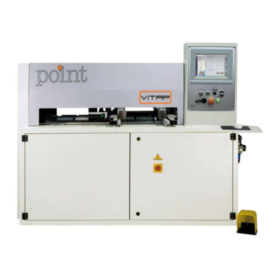
CHAPTER 2 TECHNICAL SPECIFICATIONS 2.1 MACHINE INTRODUCTION POINT is a machine designed to drill panels in laminated and non-laminated wooden chipboards, MDF, of a thickness of no more than 35mm. The operator interacts with the machine through the PC. The operation of low 24Vdc voltage machine cycles takes place through a P.L.C.
-
Page 7
MAXIMUM PANEL DIMENSION Lenght Width Height Size 270mm 150mm 12mm 3000mm/30kg 920mm 35mm TOOL FEATURES Vertical spindle cylindrical bits stems of 10 x 20 diameter and bits of Min. 30mm – Max 60mm (fitting not included). Horizontal spindle cylindrical bits stems of 10 x 20 diameter and bits of Min. 30mm – Max 37.5mm (fitting not included). -
Page 8: Machine Composition
THREE-PHASE +/-10 % NETWORK FREQ. +/-2% 50/60 50/60 50/60 Using terms: room temperature 5-40° C. Humidity unti l 90% for a temperature of 20° C. USING LIMITS These machines have been designed to process the following materials: 1) solid wood 2) Panels of laminated and non-laminated chipboards 3) M.D.F.
-
Page 9: Chapter 3 Security
— Check the wear of the tools. — In case of worn points, we suggest to replace them before using the machine following procedure described chapter “POINT REPLACEMENT/ASSEMBLY”. L. General cleaning of the machine, the workspace and the floor is an important safety factor Rel. 03…
-
Page 10
CAP. 4 INSTALLATION 4.1 MACHINE DISPLACEMENT The machine must be lifted and transported only by a lifting truck or a forklift whose forks are to be inserted under the base. See the following picture Use extreme caution when lifting of relocating the machine so as to avoid any possible danger due to sudden movements, which could provoke damage to people or objects. -
Page 11
Screw the 3 feet to the same projection Screw the 2 screws by hand (no tools) making them pull over to the floor without forcing. Tighten the locknuts Should not press into the floor. 4.3 ASSEMBLY OF DISASSEMBLED PARTS 1) WARNING REMOVE LOCKING Y AXIS Rel. -
Page 12
2) Set the keyboard support shelf 1 Block it with screws. Then position mouse, keyboard and any barcode laser gun and connect the cables of provided connectors placed under the shelf. 3) Place the intake cap A) Remove rear cover Rel. -
Page 13
B) Unlock the intake hood C) Screw the intake cap as shown D) Connect the pipes E) Replace rear cover Rel. 03… -
Page 14: Instructions For Electrical Connection
4.4 INSTRUCTIONS FOR ELECTRICAL CONNECTION THE WIRE WITH 3 OPERATING HEADS MUST HAVE A MINIMUM SECTION OF MMQ. X 6. NB. Recommendation: the machine must wired by skilled technicians. To access the electrical system of the machine, rotate the control activation knob (A) towards position 0 and open the gate (B) twisting…
-
Page 15
Verify that the section of the feeding wire is able to support the power that the machine uses up in full load. For greater safety, the wire must be protected from involuntary crushing by a raceway or an anti-crushing sheathing. Before beginning the work, verify that the rotation direction of the spindles corresponds to the direction of the pointer applied to the drilling units. -
Page 16
USB gate for PC interface “1” Luminous engine button “2” Emergency stop “3” Key selector for horizontal extra-stroke reset “4” Button Start “5” Button +/- “6” Optional output selector panel. “8” Keyboard and mouse for PC interface “7” Reducer filter group Pressurers activation electrical pedal levers Button placement the left roller Frontal stop… -
Page 17
5.2 SAFETY AND PROTECTION CATCH Emergency button If you push this button the machine will stop. To restart its operation rotate the button clockwise, then push the engine button. Emergency pedal rear seat (OPTIONAL) If you push this button the machine will stop. -
Page 18
3) Press the button 4) Press the button ,wait the group has stopped 5) Open lateral door 6) Insert or replace the tools. Tighten the screws to lock tools ATTENTION TO THE DIRECTION OF ROTATION 7) Optional GROOVE Remove the cover by unscrewing the screws Rel. -
Page 19
 Unscrewing or screwing the saw (see the picture) 9) ATTENTION TO THE DIRECTION OF ROTATION 10) Optional ROUTER : Remove the cover by unscrewing the screws 11) Unscrewing or screwing the tool see the picture Rel. 03…
 -
Page 20
12) ATTENTION TO THE DIRECTION OF ROTATION 13) close the side door 14) Press the button 15) On software press the button 16) In order to change equipping parameters it is necessary to type in protection password. 17) Click on the button shown in the picture. 18) Select the icon shown in the picture Rel. -
Page 21
19) Type in “” password in the side box PASSWORD = “ user “ 20) Then press “ok”After every change save data by pressing 21) Click 2 times on “Conf 1” quickly 22) The following screen appears: The drawing of the spindles is on the left. All the tools included in the “Tool” section are on the right. If it is not in the column, see paragraph 17 Bring mouse cursor on desired tool. -
Page 22
Move mouse cursor onto the spindle drawing. Release the left mouse button. Spindle shall change its colour thus confirming the tool change. Save changes. 23) Or press 1 time the button “Conf 1” Type the name of the tool you wish to use in the above boxes. -
Page 23
Please follow the table here-below: Parameter Insert (drilling) Insert (router) Insert ( groove) Tool name Es “tool1” Es “ TOOL12” Es “ SAW120” Tool category Tool Type Tool diameter Es “10” Es “13” Es “120” Maximum diameter Tool lenght Quote A Quote A 0,00 Maximum lenght… -
Page 24: Maintenance
2) Press the button 3) Move the left shoulder, supporting her to the panel 4) The panel must be well supported 5) Release the button 6.3 FILTER-REDUCER-LUBRICATOR GROUP (F-R-L) The correct use of the F-R-L group is the best guarantee for the normal work and long-life of the machine.
-
Page 25
CAP. 7 MACHINE PROGRAMMING This is the first screen You will find the following buttons on the top: Software keyboard: place your mouse on the left side of the screen This opens the menu: Rel. 03… -
Page 26
Press the button Rel. 03… -
Page 27
7.1 DRAWING CREATION OR CHANGE Press the icon Then appears this screen Drawings creation or opening Click on the shown icon to create a new drawing In order to open an already existing drawing, press the icon next to the previous one and select the programme to be changed. -
Page 28
Working cycles entering Icons are in the upper part: The board to be processed has the following sides: WARNING: POINT CARRIES OUT DRILLING ON SIDES 1, 3 AND 0, 2 (OPTIONAL) , 4 (OPTIONAL) . GROOVNG AND MILLING ONLY ON SIDE 0… -
Page 29
Select the side on which working cycles are to be carried out by clicking one of the following icons: Side 1 On this side drilling only is performed. Side 3 On this side drilling only is performed. Side 0 On this side drilling and grooving is performed. Side 4 On this side drilling only is performed. -
Page 30
Enter required working cycles among the following: Click this icon to view the “Drilling main menu” Single drilling Horizontal multiple drilling – outside hole reference dimension Horizontal multiple drilling – central hole reference dimension Vertical multiple drilling — outside hole reference dimension Vertical multiple drilling –… -
Page 31
Click this icon to view the “Drilling main menu on Y” 1 line Vertical multiple drilling – outside hole reference dimension 1 line Vertical multiple drilling – central hole reference dimension 1 line vertical multiple drilling special 1 line vertical multiple drilling special Click this icon to view the “Grooving main menu”… -
Page 32
Click on this icon to view the “trimming main menu” Circe complete Circumference Centre-tool trimming with dimension entering at the starting and ending point Centre-tool trimming with dimension entering at the starting point and trimming length Various geometries Various geometries Click on one of the icons listed above. -
Page 33
FACE SELECTED “1” FACE SELECTED “3” FACE SELECTED “0” Rel. 03… -
Page 34
When the dimension in X (QX) is entered it must be entered: for side 1 QX= LPX-32 for side 3 QX= 32 Where LPX corresponds to the X dimensions of the board. CAD is parametric. This means that to the three dimensions of the board an abbreviation has been assigned: LPX = dimension in X of the board A LPY = dimension in Y of the board B… -
Page 35
7.2 OPENING, CREATION, CHANGE AND START (LIST OF PROGRAMMES) Press the icon Axes resetting WHEN STARTING THE MACHINE FOR THE FIRST TIME DURING THE DAY, FOLLOW THE PROCEDURE HERE-BELOW: Press the shown button Rotate the selector into the following position in manual modality: Press the button Head will move and stop on the right side of the machine. -
Page 36
Rotate the selector into automatic modality (central position) as shown in the following picture. Only after this procedure has been completed, it is possible to start the list. Opening change creation The screen opens In order to open a new list press icon 1 In order to open an existing list press icon 2 Change or enter the following parameters… -
Page 37
3) Select the quantity of boards to be processed in column n° 2 4) Select in column n° 3 “X” to perform the mirror along the length X of the panel The machine inverts the QX face 0. Function that allows you to make the panels right and left by a single drawing. 5) Reset the list by pressing the button 6) Cancel possible previous programmes from column n°… -
Page 38
Press the button 1 Press the button 2 Fill the measure C (in mm) Press «Confirm» 9) Then click with the mouse on the first box in the upper part of column n° 1 10) Press the following button to start the working cycle The working line changes its colour. -
Page 39
11) Position the panel 12) Place front panel to stop 13) Press the electrical pedal 14) Rotate the selector to select the output side (OPTIONAL) 15) Press the button “Start” Rel. 03… -
Page 40
16) Press the electrical pedal to unlock the panel 17) To stop the list at any time, press 18) To change the size of the panel temporarily (without changing drawing) press the button in the picture Press the button This opens a window with the parameters of the panel. Change the parameters and press «Enter»… -
Page 41
19) To retrieve the size of the panel in drawing 7.3 FAILURES SIGNALLING POINT’s failures resetting Click on the icon Then the failures screen will appear. Cancel previous failures by clicking on the following button: Should failures writing still appear in the yellow or blue line, it means that the software is still detecting some failures. -
Page 42
extra-stroke position Resetting cycle in progress Wait for the completion of the machine resetting before starting the working cycle Unadjusted axes Carry out the axes resetting cycle Heating operation Check the spindles engines working Open doors safety Close the lateral door Machine working manually Signalling of the machine status, that is to say the selector is in manual position (right position). -
Page 43
E.50 List During the working cycle one stroke is parallel to the front Serv error — stroke. Move the front stroke and update software position in computing failed (#1) the“DIMENSIONS” table “Machine Data Editor” section Here below are 1 screen summarizing the parameters to which failures refer to “Tool”… -
Page 44: Software Functions
Select from the menu the head you wish to use for the working. In the upper right part of the picture the parameters which are not consistent with the working are displayed. Then it is necessary to change the drawing or change those parameters which are not consistent and which appear in the “Machine data Editor”…
-
Page 45
Zero setting The existing functions are: Automatic axis resetting 1) Select axis in the left column 2) Select the central box in the area highlighted in the picture 3) Press “Start” Machine resetting 1) Select the lower box in the area highlighted in the picture 2) Press “Start”… -
Page 46
Semiautomatic In this section it is possible to move the operating unit (TV01 reference) on the existing axes by choosing: One absolute dimension by following the procedure here-below: 1) Enter the dimension in the box pointed by the arrow 2) Select the upper box in the section highlighted in the picture 3) Press “Start”… -
Page 47
Activations In this modality it is possible to start the machine components separately. Select one of the button on the screen and then press button + or – (n° 6 of the picture) For every splinde existing the following buttons are foreseen: ON = spindle engine start MOVE = group displacement For every axis (X, Z in the picture) the “MOVE”… -
Page 48
3) Select the icon shown in the picture 4) Type in “” password in the side box . Then press “ok” PASSWORD = “ user “ 5) Press the button 6) Type in Millimetres 0 Inches 7) After every change save data by pressing Press the button Rel. -
Page 49
9) Press the button: Press the button 1 Press the button 2 , select among: 1) Draws in millimeters — Programs in millimeters (0 in the picture) 2) Draws in millimeters — Programs in inches (1 in the picture) 3) Draws in inches — Programs in millimeters (0 in the picture) 4) Draws in inches — Programs in inches (1 in the picture) -
Page 50
7.6 IMPORT FILES FROM USB FLASH DRIVE 1) Press the button 2) Press the button 3) Insert the password “xpeservice” in 1 4) Press “Ok” 2 Rel. 03… -
Page 51
5) Press the button 6) Copy: Drawing D:iLENIADRWCAD4 Joblist D:iLENIACnAutGenDistinte 7.7 PARAMETERS FOR PC CONNECTION 1) Press the button Rel. 03… -
Page 52: Daily Maintenance
2) Modify the required data 3) Press the button 1 CAP. 8 WORKING CYCLE 8.1 DESCRIPTION OF WORKING CYCLE The machine working cycle can be summarised as follows: If the length of the side to be worked is less than the half of the plane: 1) send the programme to the machine following the procedure in Chapter 7.5 2) press “Start”…
-
Page 53: Periodical Maintenance
9.2 PERIODICAL MAINTENANCE Often clean the keypad, the mouse and the shelf where the are positioned Clean the filters of the fan, on the control cabinet Take out the sawdust deposit on the guides on the rolls of the plan and on the intake cover Check that the condensate that deposit in the clear pan of the FILTER-REDUCER GROUP (F-R) has not reached the maximum limit.
-
Page 54
4) Remove rear cover 5) lubricate the parts indicated by using the greaser 9.3 RECOMMEDNATION FOR GOOD FUNCTIONING Before starting to work, make sure that tools included in the equipment corresponds to those actually installed on the machine Always check that the drilling speed are adequate, starting from lower speeds and gradually increasing speed Place the correct mobile left shoulder, see chapter 6.2 CAP. -
Page 55
Check motor fuses Broken points Replace points The running button does not start the machine Point programme is closed and light up Check that no emergency device is on (emergency button, lateral door limit switch open, right or left extra-stroke) -
Page 56
FDQDOL GL VIHUH FDQDOL GL VIHUH FDQDOL GL VIHUH URZ EDOO URZ EDOO URZ EDOO UDQJpHV GH ELOOHV UDQJpHV GH ELOOHV UDQJpHV GH ELOOHV FDQDOHV GH ERODV FDQDOHV GH ERODV FDQDOHV GH ERODV NDQlOH YRQ NXJHOQ NDQlOH YRQ NXJHOQ… -
Page 57
& 7$9 & & & & & &… -
Page 58
& & & & 7$9 & & & & … -
Page 59
& 7$9 & & & & %DVDPHQWR 0DLQIUDPH &KDVVLV 6WUXNWXU 7$9 %DVDPLHQWR… -
Page 60
ø D S i z e C o d e øD S ize C o d e 0 0 6 5 9 6 0 0 6 6 0 7 G 1 / 8 0 0 6 5 9 9 G 1 / 4 0 0 6 5 9 7 G 1 /8 0 0 6 6 0 6… -
Page 61
& & ‘LVSRVLWLYR GL 3RVL]LRQDPHQWR 3RVLWLRQLQJ ‘HYLFH ‘LVSRVLWLI GH 3RVLWLRQQHPHQW 3RVLWLRQLHUXQJ *HUlW 7$9 ‘LVSRVLWLYR GH 3RVLFLRQDPLHQWR… -
Page 62
$ 7$9 & $ 7$9 7$9 $ & & & & & & &… -
Page 63
& & 0DQGULQR 9HUWLFDOH 9HUWLFDO 6SLQGOH %URFKH 9HUWLFDOH 9HUWLNDOH 6SLQGHO 7$9 0DQGULQ 9HUWLFDO… -
Page 64
& & & & & & & 7HVWLQD 2UL]]RQWDOH +RUL]RQWDO +HDG 7rWH +RUL]RQWDO +RUL]RQWDOH .RSI 7$9 &DEH]D +RUL]RQWDO… -
Page 65
& 7$9 … -
Page 66
& & &RSHUWXUH &RYHUV &RXYHUWXUHV $EGHFNXQJ 7$9 &XELHUWDV… -
Page 67
58401579 52201582 005903 005902 58301485 52001406 008290 003930 52201414 52301415 52201414 004528 52201413 52201413 Armadio Cupboard Penderie Schrank TAV612 Armario… -
Page 68
& & & 7$9 7HVWD )RUDQWH 9LWDS %RULQJ +HDG 9LWDS 7rWH GH 3HUFHPHQW 9LWDS 7$9 & %RKUHQ .RSI 9LWDS… -
Page 69
58401579 005902 52201582 58301588 52201582 52401903 52401879 85401036 58401811 58301801 52001870 52402110 008290 003930 52201874 52301415 52201874 004528 52201872 52201872 Armadio Cupboard Penderie Schrank TAV617 Armario… -
Page 70
7$9 & & 8QLWj GL )UHVDWXUD 9HUWLFDOH 9HUWLFDO 0LOOLQJ 8QLW 8QLWp GH )UDLVDJH 9HUWLFDO 9HUWLNDOHQ )UHVRHUElQNH 7$9 )UHVDGRUDV 9HUWLFDOHV… -
Page 71
& & 3UHVVRUH (VFOXGLELOH $JJLXQWLYR $GGLWLRQDO 3UHVVHU ([FOXGDEOH 3UHVVHXU $GGLWLRQQHO ([FOXDEOHV :HLWHUH 3UHVVHUIX‰DXWRPDWLN $XVJHVFKORVVHQ 7$9 3UHQVDWHODV $GLFLRQDOHV ([FOXLEOHV… -
Page 72
Tensione esercizio: 400V. Progetto: 58201802 «Foratrice» Tensione ausiliari: 24VAC Commessa: Frequenza: 50Hz Cliente: Corrente nominale: Disegnatore: Mannucci F. Potenza totale: Data: 30/09/2009 Grado di protezione: Via Dei Gelsi 31 53036 loc Pian dei Peschi Poggibonsi (Si) Tel. 0577-978086 Fax 0577-977159 AUTOMAZIONE Quadri elettrici per e-mail: mannucci@mpfautomazione.com — www.mpfautomazione.com… -
Page 73
2-L1 2-L1 03.0 2-L2 2-L2 03.0 2-L3 2-L3 03.0 -QS1 -FU4 8-L1 8-L2 8-L3 -KM1 -KM2 2-L1 05.8 05.9 2-L2 2-L3 05.8 05.9 -FA1 -FA2 09.7 {} 09.8 {} 1,5 N 1,5 N Motore lama Motore testa forare 2,6 A. 3,5A. -
Page 74
-FU2 24VDC 24VDC 24VDC +24V +24V +24V 04.4 04.4 04.4 0VDC 0VDC 0VDC 0V24 0V24 0V24 04.5 04.5 04.5 O-06 O-03 O-04 06.4 06.3 06.3 O-02 06.2 Rosa Rosa Rosa X AN+ Y AN+ Z AN+ 400V Bianco Bianco Bianco 3KVA X AN- REF/… -
Page 75
4-L1 03.1 4-L2 03.1 -FU10 10-L1 10-L2 0-230-400-415V -TC1 -GS1 100VA 50-60 -XT2 -FU11 Ventola armadio PROGETTO: 58201802 «Foratrice» FOGLIO CLIENTE: COMMESSA: TITOLO: ALIMENTAZIONI Quadri elettrici per automazione REV. DATA FIRMA MODIFICA DIS.: Mannucci F. DATA: 30/09/2009… -
Page 76
24VAC 04.3 24VDC 24VAC1 04.4 07.6 -SQ3 -SQ4 -SB2 A1 (L+) A2 (L-) pilz -SQ1 PNOZ X2 PNOZ X2.1 -SB1 1 0 2 -SA3-3 -FA1 -FA2 -SQ2 02.5 02.7 -SHB2 -YV1 -KM1 -KM2 +QUADRO +QUADRO -KM4 +QUADRO 0VAC 0VAC 04.3 PROGETTO: 58201802 «Foratrice»… -
Page 77
24VDC X2-200 0VDC I-08 O-01 24VAC X2-I-08 04.3 O-02 24VDC1 03.3 05.6 O-03 03.5 O-04 03.8 I-03 X2-I-03 X2-I-02 X2-I-01 O-06 03.2 I-02 O-07 X1-109 X1-116 O-08 X1-117 I-01 0VDC +24V +24V 24VDC 0VDC… -
Page 78
24VDC -SQ8 -SQ9 -SQ10 -SQ11 -SQ12 -SQ13 -SB4-1 -SB4-2 I-12 I-11 I-14 I-10 I-15 I-09 I-16 O-12 (Bianco/Giallo) O-11 (Marrone) O-10 (Bianco) 0VDC O-09 (Bianco/Verde) -YV4 -YV3 -YV2 -YV20 0VDC 0VDC PROGETTO: 58201802 «Foratrice» FOGLIO CLIENTE: COMMESSA: TITOLO: CNI ESPANZIONE 1 Quadri elettrici per automazione REV. -
Page 79
24VDC 24VDC 1 0 2 -SB3 -SQ16 -SQ14 -SQ15 -SA3-2 -SA3-1 I-20 I-22 I-19 I-23 I-18 I-24 I-17 O-24 (Rosso/Blu) O-23 (Grigio/Rosa) O-22 (Rosso) O-21 (Blu) O-20 (Rosa) O-19 (Grigio) 0VDC O-18 (Giallo) O-17 (Verde) -YV12 -YV11 -YV10 -YV9 -YV8 -YV7 -YV6 -YV5… -
Page 80
24VDC -FA1 -FA2 02.5 02.7 O-32 (Giallo/Marrone) O-31 (Bianco/Rosa) O-30 (Viola) O-29 (Nero) O-28 (Marrone/Verde) O-26 (Grigio /Marrone) 0VDC O-25 (Bianco/Grigio) -YV19 -YV18 -YV14 -YV13 -YV17 -YV16 -YV15 PROGETTO: 58201802 «Foratrice» FOGLIO CLIENTE: COMMESSA: TITOLO: CNI ESPANZIONE 3 Quadri elettrici per automazione REV. -
Page 81
alta bassa — + PE bassa PROGETTO: 58201802 «Foratrice» FOGLIO CLIENTE: COMMESSA: TITOLO: Scheda switch encoder Quadri elettrici per automazione REV. DATA FIRMA MODIFICA DIS.: Mannucci F. DATA: 30/09/2009… -
Page 82
Morsettiera F.Corsa porte aperte Emergenze aggiuntive 24VAC1 24VAC1 Elettrovalvola 0VAC 0VAC scarico aria O-01 O-01 24VAC1 24VAC1 0VAC 0VAC 24VDC 24VDC 0VDC 0VDC I-22 I-22 I-23 I-23 I-13 I-13 I-14 I-14 I-19 I-19 O-08 O-08 O-07 O-07… -
Page 83
PROGETTO: 58201802 «Foratrice» FOGLIO CLIENTE: COMMESSA: TITOLO: Morsettiera: X1 Quadri elettrici per automazione X1 — 2/2 REV. DATA FIRMA MODIFICA DIS.: Mannucci F. DATA: 30/09/2009… -
Page 84
Morsettiera Riserva 0VDC Riserva 0VDC Riserva 0VDC Riserva 0VDC 0VDC Riserva 0VDC Riserva 0VDC Riserva 0VDC Riserva 0VDC Riserva 0VDC Riserva 0VDC Riserva 24VDC Riserva 24VDC Riserva 24VDC Riserva 24VDC Riserva 24VDC 24VDC Riserva 24VDC Riserva 24VDC Riserva 24VDC Riserva 24VDC Riserva 24VDC… -
Page 85
Morsettiera I-15 I-15 Trascinatore dx alto(III) I-15 I-16 I-16 Trascinatore sx alto(IIII) I-16 I-17 I-17 Battuta frontale indietro(II) I-17 I-18 I-18 Battuta frontale avanti(I) I-18 I-20 I-20 Porte aperte I-20 I-21 I-21 Pressostato aria ok I-21 I-24 I-24 Pedale bloccaggio I-24 I-26 I-26… -
Page 86
LISTA MATERIALI Sigla Descrizione Ubicazione Posizione 06.2 CPU CNI QUADRO Espansione CNI nr. 1 QUADRO 07.4 Espanzione CNI nr. 2 08.4 QUADRO Espanzione CNI nr. 3 09.5 QUADRO Driver comando motore asse X 03.3 QUADRO 03.6 Driver comando motore asse Z QUADRO Driver comando motore asse Y QUADRO… -
Page 87
LISTA MATERIALI Sigla Descrizione Ubicazione Posizione 05.2 Finecorsa estra corsa asse X — IMPIANTO SQ10 Extra corsa + asse Y IMPIANTO 07.5 Extra corsa — asse Z 07.6 SQ11 IMPIANTO Sensore trascinatore dx alto 07.8 SQ12 IMPIANTO Sensore trascinatore sx alto 07.9 SQ13 IMPIANTO… -
Page 88
INDICE PAGINE Gruppo N° pagina Titolo Revisione Data ultima revisione Cronologia POTENZA copertina POTENZA POTENZA POTENZA POTENZA ASSi POTENZA ALIMENTAZIONI POTENZA MODULO SICUREZZA COMANDO CNI CPU COMANDO CNI ESPANZIONE 1 COMANDO CNI ESPANZIONE 2 COMANDO CNI ESPANZIONE 3 COMANDO Scheda switch encoder MORSETTIERE Morsettiera: X1 MORSETTIERE…
 Unscrewing or screwing the saw (see the picture) 9) ATTENTION TO THE DIRECTION OF ROTATION 10) Optional ROUTER : Remove the cover by unscrewing the screws 11) Unscrewing or screwing the tool see the picture Rel. 03…
 - Manuals
- Brands
- point Manuals
- Industrial Equipment
- Vitap
Manuals and User Guides for point Vitap. We have 1 point Vitap manual available for free PDF download: Instruction Manual
|
Detail Specifications: 2416/2416682-vitap.pdf file (27 Dec 2022) |
Accompanying Data:
point Vitap Industrial Equipment PDF Instruction Manual (Updated: Tuesday 27th of December 2022 05:53:08 AM)
Rating: 4.3 (rated by 6 users)
Compatible devices: 108 463C, 6200X, LE 5000 DF, GGHG, AllSky 52187, Sartoclear Pilot Filter Holder, HACK 130-200, DJS FOR DST AND PST 2Nm SOFT.
Recommended Documentation:
Text Version of Instruction Manual
(Ocr-Read Summary of Contents, UPD: 27 December 2022)
-
15, point Vitap Rel. 03 14 Verify that the section of the feeding wire is able to support the power that the machine uses up in full load. For greater safety, the wire must be protected from involuntary crushing by a raceway or an anti-crushing sheathing. Before beginning the work, verify that the rotation direction of the spindles corresponds to the direction…
-
45, Rel. 03 44 Zero setting The existing functions are: — Automatic axis resetting 1) Select axis in the left column 2) Select the central box in the area highlighted in the picture 3) Press “Start” — Machine resetting 1) Select the lower box in the area highlighted in the picture 2) Press “Start” Manual In this sectio…
-
72, Progetto: Commessa: Disegnatore: Cliente: Tensione esercizio: Tensione ausiliari: Frequenza: Rev. Modifiche Data ApprovatoVerificatoPreparato 58201802 «Foratrice» 30/09/2009 24VAC 50Hz 400V. Via Dei Gelsi 31 53036 loc Pian dei Peschi Poggibonsi (Si) Tel. 0577-978086 Fax 0577-977159 e-mail: [email protected] — www.mpfautomazione.com E’ FATTA RISERVA D…
-
84, TITOLO: DATA: PROGETTO: FOGLIO 30/09/2009 58201802 «Foratrice» Morsettiera: X2 13 CLIENTE: Quadri elettrici per automazione DATA FIRMAREV. MODIFICA DI 17 X2 — 1/2 DIS.: Mannucci F. 12 14 COMMESSA: 0 1 2 3 4 5 6 7 8 9 24VDC 24VDC 24VDC 24VDC 24VDC 24VDC 24VDC 24VDC 24VDC 0VDC 0VDC 0VDC 0VDC 0VDC 0VDC 0VDC 0VDC 0VDC 0VDC 24VDC Sensore zero X Sensore zero Y Sensore zero Z Laser …
-
67, point Vitap Armadio Cupboard Penderie Schrank Armario TAV612 003930 52001406 52201414 008290 52201413 52301415 52201582 005903 005902 58301485 58401579 004528 52201413 52201414
… -
31, point Vitap Rel. 03 30 Click this icon to view the “Drilling main menu on Y” 1 line Vertical multiple drilling – outside hole reference dimension 1 line Vertical multiple drilling – central hole reference dimension 1 line vertical multiple drilling special 1 line vertical multiple drilling special Click th…
-
69, Armadio Cupboard Penderie Schrank Armario TAV617 003930 52001870 52201874 52201872 52301415 52201582 52201582 005902 58401579 004528 52201872 52201874 58301801 58401811 52401879 52401903 58301588 85401036 008290 52402110
… -
78, point Vitap TITOLO: DATA: PROGETTO: FOGLIO 30/09/2009 58201802 «Foratrice» CNI ESPANZIONE 1 07 CLIENTE: Quadri elettrici per automazione DATA FIRMAREV. MODIFICA DI 17 DIS.: Mannucci F. 06 08 COMMESSA: 0 1 2 3 4 5 6 7 8 9 O-13 0VDC 24VDC I-12 I-11 I-10 I-09 O-10 (Bianco) O-11 (Marrone) O-12 (Bianco/Giallo) 24VDC1 I-15 I-16 I-14 I-13 O-16 0VDC 24VAC3 24VAC1 0VDC O-…
-
76, TITOLO: DATA: PROGETTO: FOGLIO 30/09/2009 58201802 «Foratrice» MODULO SICUREZZA 05 CLIENTE: Quadri elettrici per automazione DATA FIRMAREV. MODIFICA DI 17 DIS.: Mannucci F. 04 COMMESSA: 0 1 2 3 4 5 6 7 8 9 O-16 O-13 0VAC 106 107 O-01 0VAC 103 102 24VAC 24VAC 24VDC 24VDC 24VAC1 0VAC 24VAC1 24VAC1 24VAC1 24VAC1 24VDC1 1 0 2 pilz PNOZ X2 PNOZ X2.1 K1 K2 …
-
48, Rel. 03 47 3) Select the icon shown in the picture 4) Type in “” password in the side box . Then press “ok” PASSWORD = “ user “ 5) Press the button 6) Type in 7) After every change save data by pressing
… -
5, Rel. 03 4 CAP. 1 GENERAL INFORMATION 1.1 PREMISE TO THE OPERATIONS MANUAL This instructions manual is aimed at machine operators and above all, at the technical staff, whose responsibility is the correct use of the machine as per safety purposes. We therefore recommend that you read it carefully, particularly the paragraphs on warni…
Recommended Instructions:
50HE003-006, 7379, FRS20ZGG, MD230


-
5-376-000094REV. 3 — 03/10© 2010 Jerr-Dan Corporation. All Rights Reserved.HDR 70/85WRECKEROPERATIONS AND MAINTENANCEMANUAL$35.001080 Hykes RoadGreencastle, PA 17225Phone (717) 597-7111www.jerr-dan.comEastern Wrecker Sales Inc …
JERR-DAN HDR 70/85-530 106
-
FDHANDLEsHandle and Shield Replacement kit.Installation Instructions / Instructivo de InstalaciónUse only with Siemens certified Components.Utilizar únicamente con componentes certificados por Siemens.A utiliser uniquement avec les composants certifiés Siemens.Item: FDHANDLETurn off and lock out all power supplying this device before working on this device.Replace all cov …
FDHANDLE 5
-
CALIBRATION PROCEDURENI 9215This document contains the verification and adjustment procedures for the National Instruments 9215. In this document, the NI 9215 with screw terminal and the NI 9215 with BNC are referred to inclusively as the NI 9215. For more information about calibration solutions, visit ni.com/calibration.ContentsSoftware Requirements……………. …
NI 9215 8
-
Assembly instructions3 842 358 724/2013-04Replaces: –EnglishBS 2/C-100BS 2/C-HBS 2/R-700BS 4/R-700BS 2/R-300BS 4/R-300BS 2/R-HBS 2/R-V-1200BS 2/C-250BS 2/C-…, BS 2/R-…Belt sectionsApplies to the following types:3 842 998 096 , BS 2/R-7003 842 998 097 , BS 4/R-3003 842 998 238 , BS 2/R-H3 842 998 239 , BS 2/C-H3 842 998 492 , BS 2/R-V-12003 842 999 901 , BS 4/R-7003 842 999 …
Rexroth BS 2/C Series 76
Additional Information:
Operating Impressions, Questions and Answers:
Download Instruction manual of point Vitap Industrial Equipment for Free or View it Online on All-Guides.com.

1

2

3

4

5

6

7

8

9

10

11

12

13

14

15

16

17

18

19

20

21

22

23

24

25

26

27

28

29

30

31

32

33

34

35

36

37

38

39

40

41

42

43

44

45

46

47

48

49

50

51

52

53

54

55

56

57

58

59

60

61

62

63

64

65

66

67

68

69

70

71

72

73

74

75

76

77

78

79

80

81

82

83

84

85

86

87

88

89

INSTRUCTIONS MANUAL
POINT
Rel. 03
WOODWORKING MACHINES
53036 POGGIBONSI (SIENA) ITALY
FAX 0577-981670
VIA PISANA 149 TEL 0577-987511
Vitap
WEB www.vitap.it
Point K2 2.0 is the technological evolution of numerical control machines for wood processing. The power of 4 machines is concentrated in a revolutionary machining center: cutting unit, profile unit, drilling unit, routering-nesting.
The innovative patented Vitap Bar Nesting System®️ technology allows the 5 faces of the panel to be machined in just 4 minutes.
Among the features that make Point K2 2.0 unique, there is the patented DDT System Double Dynamic Transport®️ technology, a double clamp technology for seamless panel movement, and the 4 sides milling device 0-3 mm.
Point K2 2.0 has a new automatic tool changer warehouse and has a working area (Y axis) of 1250 mm.
Point K2 2.0 doesn’t need suckers nor reverse profiles: it speeds up production processes and reduces operating costs. Compact and light, it takes only 5sqm.
Thanks to the modern software interface and PC control, programming is easy and direct. Thanks to Point K2 2.0, even unskilled operators can achieve excellent quality work at high production speeds.
This is why Point K2 2.0 is the ideal CNC for wood, both for large companies that need high productivity without the typical costs of large CNC, and for small and medium-sized companies with limited budgets and stocking space.
-
Andrei4
- Новичок
- Сообщения: 2
- Зарегистрирован: 07 апр 2016, 22:53
- Репутация: 0
- Настоящее имя: Андрей
- Контактная информация:
-

Карабас
- Мастер
- Сообщения: 1862
- Зарегистрирован: 02 мар 2016, 06:53
- Репутация: 690
- Контактная информация:

Re: Нужна помощь Vitap Point 2
Сообщение
Карабас » 11 апр 2016, 21:25
Он же вам русским языком говорит -нажата кнопка СТОП.
Если на минусы жизни смотреть сквозь поднятый средний палец, то они становятся плюсами.
-
Andrei4
- Новичок
- Сообщения: 2
- Зарегистрирован: 07 апр 2016, 22:53
- Репутация: 0
- Настоящее имя: Андрей
- Контактная информация:
Re: Нужна помощь Vitap Point 2
Сообщение
Andrei4 » 14 апр 2016, 21:13
Проревели кнопку Стоп и педаль за одно-рабочие, проблема осталась. Есть ещё какие нибудь варианты? или расшифровка кода для Point2 ?
В чем проблема понять не могу.
-
solo73
- Новичок
- Сообщения: 1
- Зарегистрирован: 25 май 2016, 10:43
- Репутация: 0
- Настоящее имя: Alex
- Контактная информация:
Re: Нужна помощь Vitap Point 2
Сообщение
solo73 » 25 май 2016, 10:53
Добрый день — сгорела флешка на ПК — Vitap Point 2 ![]()
Работа встала ОЧЕНЬ нужен образ флешки (формат gho)
Помогите кто сможет !!!!! HELP !!!
Заранее благодарен.
-
lexx_l
- Опытный
- Сообщения: 110
- Зарегистрирован: 31 окт 2015, 22:43
- Репутация: 11
- Настоящее имя: Алексей
- Откуда: Днепр
- Контактная информация:
Re: Нужна помощь Vitap Point 2
Сообщение
lexx_l » 25 май 2016, 13:26
проверяйте проводку — при перевозке чегото отвалилось — по цепи стоп. проверяйте проводку аж до компа.
-
Юрий1986
- Новичок
- Сообщения: 1
- Зарегистрирован: 05 окт 2016, 10:55
- Репутация: 0
- Настоящее имя: Юрий
- Контактная информация:
Re: Нужна помощь Vitap Point 2
Сообщение
Юрий1986 » 06 окт 2016, 12:47
Добрый день.
Нужна помощь. Купили бу Vitap point 2 с ILENIA.
Всё КД на деревяшки выполнено в Solidworks.
Как экспортировать файлы солида в илению. пробовал через dxf, но станок выдаёт ошибку и/или некоторые детали открывает, но не определяет отверстия и линии.
Может, кто сталкивался с такой проблемой, подскажите, пожалуйста.
Может кто знает как из солида конвертировать в родной формат илении *pd4?
Заранее благодарю.
-
андрей эндрю
- Новичок
- Сообщения: 1
- Зарегистрирован: 23 авг 2018, 09:47
- Репутация: 0
- Настоящее имя: андрей николлаевич
- Контактная информация:
Re: Нужна помощь Vitap Point 2
Сообщение
андрей эндрю » 23 авг 2018, 09:56
добрый день всем !!! нужен образ флэшки витап поинт 2 !!! кто может -помогите , отббллагодарим . мой номер 89126861281 андрей
-
poderevu
- Новичок
- Сообщения: 3
- Зарегистрирован: 11 июн 2020, 15:33
- Репутация: -1
- Настоящее имя: Юрий
- Контактная информация:
Re: Нужна помощь Vitap Point 2
Сообщение
poderevu » 11 июн 2020, 15:43
Подскажите, сталкивался ли кто —
Станок не калибрует энкодер (по оси Х) в параметре transmission B, (от 0 — все ок), отверстия 100 — 1100 получаются (от икса) 100 и 1099 (т.е. 1 миллиметр с одного метра! — 2 мм с 2х метров).
Заготовки до 500мм идут без погрешностей!
uriy_2000@mail.ru — если кто сталкивался и видит данное письмо, пожалуйста свяжитесь со мной!
-
poderevu
- Новичок
- Сообщения: 3
- Зарегистрирован: 11 июн 2020, 15:33
- Репутация: -1
- Настоящее имя: Юрий
- Контактная информация:
Re: Нужна помощь Vitap Point 2
Сообщение
poderevu » 11 июн 2020, 15:49
Andrei4, привет! Я понимаю, что прошло 4 года, но все же спрошу.. Нет ли случайно образа системы на твой станок? если конечно не продали еще..