- Manuals
- Brands
- Viessmann Manuals
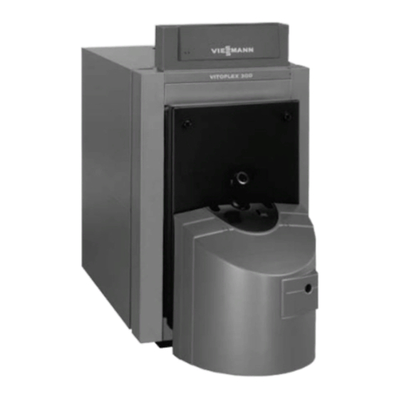
- Boiler
- Vitoflame 100
- Service instructions manual
-
Contents
-
Table of Contents
-
Troubleshooting
-
Bookmarks
Quick Links
Service instructions
for heating engineers
Vitoflame 100
Pressure−jet oil burner (type VE III)
H for Vitoplex 100, 200 and 300
Rated output 80 to 225 kW
H for Vitorond 200
Rated output 125 to 195 kW
For applicability, see the last page.
VITOFLAME 100
5692 623 GB
9/2005
Please keep safe
Related Manuals for Viessmann VITOFLAME 100
Summary of Contents for Viessmann VITOFLAME 100
-
Page 1
Service instructions for heating engineers Vitoflame 100 Pressure−jet oil burner (type VE III) H for Vitoplex 100, 200 and 300 Rated output 80 to 225 kW H for Vitorond 200 Rated output 125 to 195 kW For applicability, see the last page. -
Page 2: General Information
General information Safety instructions ¨ Please follow these safety instructions closely to prevent accidents and material losses. Safety instructions explained Regulations ¨ Danger Observe the following when working This symbol warns against the on this system H all legal instructions regarding the risk of injury.
-
Page 3
H Ventilate the boiler room. Replace faulty components H Close the gas shut−off valve. only with original Viessmann spare parts. Working on the heating system Ancillary components, spare and H Isolate the system from the power… -
Page 4: Table Of Contents
Capacity Index Page General information Safety instructions ……………………Initial start−up, inspection and maintenance Steps Initial start−up, inspection and maintenance .
-
Page 5: Initial Start−Up, Inspection And Maintenance
Initial start−up, inspection and maintenance Steps Initial start−up, inspection and maintenance For further instructions on individual steps, see pages indicated. Commissioning steps Inspection steps Maintenance steps Page 1. Starting the heating system ……….2.
-
Page 6: Further Details Regarding The Individual Steps
Initial start−up, inspection and maintenance Further details regarding the individual steps To obtain optimum combustion values, the burner must be adjusted with the boiler heated to operating temperature (min. 60 ºC). Also carry out measurements at base load. Starting the heating system Boiler control unit service instructions 1.
-
Page 7: Checking The Adjustment Of The Air Damper Servomotor
Initial start−up, inspection and maintenance Further details regarding the individual steps (cont.) Checking the adjustment of the air damper servomotor The burner is equipped with an air damper servomotor with adjustable switch cams used to position the air damper plus a solenoid valve control.
-
Page 8: Adjusting The Oil Pressure And Checking The Vacuum
Initial start−up, inspection and maintenance Further details regarding the individual steps (cont.) Adjusting the oil pressure and checking the vacuum The oil pressure is preset at the factory according to the oil throughput. Readjust the oil pressure, if required. 1. Switch OFF the mains isolator and safeguard against unauthorised reconnection.
-
Page 9
Initial start−up, inspection and maintenance Further details regarding the individual steps (cont.) 7. If required, adjust the oil pressure at pressure adjusting screw C for stage 1 and D for stage 2. ³ pressure rises Clockwise Anti−clockwise ³ pressure falls. For standard burner settings, see page 38. -
Page 10: Adjusting The Air Volume
Initial start−up, inspection and maintenance Further details regarding the individual steps (cont.) Adjusting the air volume The air volume is preset at the factory. If required, adjust the air volume; for this, first adjust the air volume for stage 2 at the blast tube connection. Starting up the burner may require a fine adjustment.
-
Page 11
Initial start−up, inspection and maintenance Further details regarding the individual steps (cont.) Readjusting stage 1 1. Change service switch B to position II (automatic mode) and close the flap. 2. Change the burner to stage 1 by pulling plug lÖ. 3. -
Page 12: Cleaning And Checking The Flame Monitor
Initial start−up, inspection and maintenance Further details regarding the individual steps (cont.) Cleaning and checking the flame monitor Remove flame monitor A (photo resistance) from its retainer, whilst the burner is operating. The system should then perform a fault shutdown if the flame monitor is covered up.
-
Page 13: Cleaning The Burner
Initial start−up, inspection and maintenance Further details regarding the individual steps (cont.) Cleaning the burner 1. Set the burner into its Cleaning the combustion maintenance position. chamber and hot gas flues, see boiler service 2. Clean the casing, the flame tube, instructions.
-
Page 14: Replacing The Nozzle
Initial start−up, inspection and maintenance Further details regarding the individual steps (cont.) Replacing the nozzle 1. Remove sensor plate A from the blast tube connection. 2. Replace nozzle B (prevent the blast tube connection from turning); during this step prevent air bubbles from forming in the blast tube connection.
-
Page 15: Checking And Adjusting The Ignition Electrodes
Initial start−up, inspection and maintenance Further details regarding the individual steps (cont.) Checking and adjusting the ignition electrodes Check ignition electrodes A for wear, contamination and size (see fig.) and replace, if required. + 0.3 80 kW 14 mm (105 kW) 13 mm (90 kW) 12 mm (120, 130 and 150 kW) 5 mm (105 kW)
-
Page 16: Cleaning And Replacing The Oil Pump Filter, If Required
Initial start−up, inspection and maintenance Further details regarding the individual steps (cont.) Cleaning and replacing the oil pump filter, if required Danfoss oil pump, type BFP 52 A Filter plug B O−ring (replace) C Filter (replace) Suntec oil pump, type AT 2 55 A Filter (clean or replace)
-
Page 17: Operating And Service Documents
Initial start−up, inspection and maintenance Further details regarding the individual steps (cont.) Operating and service documents 1. Complete and detach the 2. Keep all parts lists, operating and customer registration card: service instructions in the folder H Give the system user this part and hand this over to the system for safe−keeping.
-
Page 18: Burner Control Unit
Initial start−up, inspection and maintenance Burner control unit Program sequence during commissioning 1 qW Plug−in terminals on the Start command B B’ Interval for flame to build burner control unit E Burner motor Burner operating position F Solenoid valve stage 2 achieved H Solenoid valve stage 1 Burner operation…
-
Page 19: Troubleshooting
Troubleshooting Diagnostics Fault Cause Remedy Burner does not start No voltage Check the fuse in the control unit or in the plug−in panel; check the electrical connections, the position of the ON/OFF switch at the control unit and that of the mains isolator.
-
Page 20
Troubleshooting Diagnostics (cont.) Fault Cause Remedy Pump does not supply oil Shut−off valves closed at Open valves filter or in oil pipe Filter blocked Clean filter (pre−filter and pump filter) Coupling between Replace coupling motor and pump faulty Suction pipe leaking Tighten connections. -
Page 21
Troubleshooting Diagnostics (cont.) Fault Cause Remedy Flame extinguishes Air in suction line Seal line and filter during operation Nozzle faulty Replace nozzle Air incorrectly adjusted; Adjust pre−settings pump pressure correctly (see page 38) incorrectly adjusted Interior of the sensor Clean the interior of the plate and flame tube sensor plate and flame contaminated… -
Page 22: Components Overview
Components overview Components overview Legend 1 Service switch (for burner qT Fan motor qZ Servomotor adjustment) 2 Hood adaptor qU Fan housing 3 Fixing plate for burner hood qI Inlet air silencer qO Impeller adaptor 4 Quick−acting closure wP Air regulating valve 5 Ignition transformer wQ Flame monitor 6 Burner control unit…
-
Page 23
Components overview Components overview (cont.) qP + qE +… -
Page 24: Connection And Wiring Diagrams
Connection and wiring diagrams Connection and wiring diagram Flame monitoring through photo resistance 6.3A (slow) 250V Jumper…
-
Page 25: H Flame Monitoring Through Light Flicker Detector
Connection and wiring diagrams Connection and wiring diagram (cont.) Flame monitoring through light flicker detector 6.3A (slow) 250V Jumper…
-
Page 26
Connection and wiring diagrams Connection and wiring diagram (cont.) Note This wiring diagram only applies in conjunction with Viessmann products. A Control unit components Burner plug on control unit 90 D B Burner control unit Internal connection with plug−in connector lÖ… -
Page 27: Parts List
Parts list Parts list When ordering spare parts: 065 Solenoid valve nut for oil pump Quote the type and serial no. (see (Suntec) type plate) and the item no. of the 081 Strapping plug no. 121 required part (as per this parts list). 082 Fuse 4 A/250 V (slow) Obtain standard parts from your 085 Silencer hood…
-
Page 28
Parts list Parts list (cont.) 003 Small parts comprising: Parts not shown 3a Cheese−head screw M 6 × 16 051 Allen grub screw SW 5 3b Cheese−head screw M 6 × 10 052 Burner housing pack 3c Serrated washer A 6.4 053 Installation instructions 3d Twin clip 18 ×… -
Page 29
Parts list Parts list (cont.) -
Page 30
Parts list Parts list (cont.) -
Page 31
Parts list Parts list (cont.) -
Page 32
Parts list Parts list (cont.) -
Page 33
Parts list Parts list (cont.) -
Page 34
Parts list Parts list (cont.) -
Page 35: Appendix
Appendix Specification In conjunction with Vitoplex 100 and Vitoplex 300 Rated boiler output Burner output 61/87 80/115 99/142 130/186 171/245 Stage 1/2* Burner type VE III 1 VE III 2 VE III 2 VE III 3 VE III 4 Type test no. 5 G 399/ 5 G 400/ 5 G 400/…
-
Page 36
Appendix Specification (cont.) In conjunction with Vitoplex 200 Rated boiler output Burner output 68/97 91/130 114/163 152/217 Stage 1/2* Burner type VE III 2 VE III 2 VE III 3 VE III 4 Type test no. 5 G 399/ 5 G 400/ 5 G 400/ 5 G 422/ to EN 267… -
Page 37
Appendix Specification (cont.) In conjunction with Vitorond 200 Rated boiler output Burner output 95/136 122/174 149/213 Stage 1/2* Burner type VE III 2 R VE III 3 R VE III 4 R Type test no. 5 G 400/04 S 5 G 421/05 S 5 G 422/05 S to EN 267 Voltage Frequency… -
Page 38: Standard Burner Settings
Appendix Standard burner settings Note Check that the service instructions are valid for the burner concerned (see notes on applicability, page 44 and serial no. on the burner type plate). In conjunction with Vitoplex 100 and Vitoplex 300 Rated output Oil burner nozzle Make Delavan…
-
Page 39
Appendix Standard burner settings (cont.) In conjunction with Vitoplex 200 Rated output Oil burner nozzle Make Delavan Type 60º B 60º B Fluidics Type 60º H Steinen Type 60º H 1.75 2.25 2.75 3.25 Oil pressure approx. Stage 1 bar min. Stage 2 18.5 Oil flow rate… -
Page 40
Appendix Standard burner settings (cont.) In conjunction with Vitorond 200 Rated output Oil burner nozzle Make Delavan Type 60º W 60º W 60º W 2.00 2.75 3.25 Oil pressure approx. Stage 1 bar min. Stage 2 Oil flow rate Stage 1 kg/h 10.3 12.4… -
Page 41: Commissioning/Service Report
Appendix Commissioning/service report Setting and test values Initial start−up Maintenance/ service Oil pressure H Stage 1 actual H Stage 2 actual Vacuum actual after maint. Smoke spot number H Stage 1 actual after maint. H Stage 2 actual after maint. Carbon dioxide content CO H Stage 1 % by vol.
-
Page 42
Appendix Commissioning/service report (cont.) Setting and test values Initial start−up Maintenance/ service Flue gas loss H Stage 1 actual H Stage 2 actual Draught (at the boiler back) actual Blast tube connection actual setting actual Air damper setting Position of the switch cams at the air damper servomotor º… -
Page 43: Keyword Index
Appendix Keyword index Adjusting the air volume, 10 Parts list, 27 Applicability, 44 Safety instructions, 2 Burner cleaning, 13 Specification, 35 Standard burner settings, 38 Starting the system, 6 Commissioning/service report, 41 Steps, 5 Components overview, 22 Connection and wiring diagrams, 24 Troubleshooting, 19 Diagnostics, 19 Vacuum, checking, 8…
-
Page 44: Applicability
Applicability from serial no. 7188626 5 00001 kkk, 7188627 5 00001 kkk, 7188628 5 00001 kkk and 7188629 5 00001 kkk Viessmann Werke GmbH & Co KG D 35107 Allendorf Tel: +49 6452 70 0 Fax: +49 6452 70 27 80 www.viessmann.de…
Viessmann Vitoflame 100: List of Available Documents
Note for Owners:
Guidesimo.com webproject is not a service center of Viessmann trademark and does not carries out works for diagnosis and repair of faulty Viessmann Vitoflame 100 equipment. For quality services, please contact an official service center of Viessmann company. On our website you can read and download documentation for your Viessmann Vitoflame 100 device for free and familiarize yourself with the technical specifications of device.
More Burner Devices:
-
baltur GI 350 DSPGN
— Istruzioni per bruciatori modello- Instruction for burners model- Instrucciónes para quemadores modelos- Mode d’emploi bruleûrGI 350 DSPGNGI 420 DSPGNGI 510 DSPGN0006080106_2007060006080106_200706IT — GB — SP — FRIT — GB — SP — FR …
GI 350 DSPGN Burner, 114
-
Barton 95516
SAVE THIS MANUAL: KEEP THIS MANUAL FOR SAFETY WARNINGS, PRECAUTIONS, ASSEMBLY, OPERATING, INSPECTION, MAINTENANCE AND CLEANING PROCEDURES. WRITE THE PRODUCT’S SERIAL NUMBER ON THE BACK OF THE MANUAL NEAR THE ASSEMBLY DIAGRAM (OR MONTH AND YEAR OF PURCHASE IF PRODUCT HAS NO NUMBER).OWNER’S MANUAL AND SAFETY INSTRUCTIONSITEM: 95516FOR QUESTIONS PLEASE CALL OUR CUSTOMER SUPPORT: (909) 628 0880 …
95516 Burner, 7
-
baltur COMIST 18
2001/07Edizione / Edition• — Leggere attentamente le istruzioni prima di mettere in funzione il bruciatore o di eseguire lamanutenzione.- I lavori sul bruciatore e sull’impianto devono essere eseguiti solo da personale qualificato.- L’alimentazione elettrica dell’impianto deve essere disinserita prima di iniziare i lavori.- Se i lavori non sono eseguiti correttamente si rischiano incident …
COMIST 18 Burner, 35
-
Viking 30”W
Viking Range, LLC 111 Front StreetGreenwood, Mississippi 38930 USA(662) 455-1200For product informationcall 1-888-(845-4641),or visit the Viking Web site atvikingrange.comF21338 EN (123113)Use & Care ManualProfessional/Custom Panel Built-In All Refrigerator/Freezer …
30”W Refrigerator, 18
-
Town & Country Fireplaces TC36
SERIAL #TC36 & TC36ARCHINSTALLATION AND OPERATING INSTRUCTIONS180315-48 TC36_D & TC36_DAR 5056.427DMODEL: TC36 & TC36AR SERIES DMODULAR DIRECT VENTFIREPLACEWARNING: If the information in these instructi …
TC36 Indoor Fireplace, 48
Recommended Documentation:
Download Service instructions manual of Viessmann Vitoflame 100 Boiler, Burner for Free or View it Online on All-Guides.com.

1

2

3

4

5

6

7

8

9

10

11

12

13

14

15

16

17

18

19

20

21

22

23

24

25

26

27

28

29

30

31

32

33

34

35

36

37

38

39

40

41

42

43

44

45

46

47

48

49

50

51

52

53

54

55

56

Service instructions
for contractors
VIESMANN
Vitoflame 100
Type VEH III
Pressure-jet oil burner
for Vitoplex 200 and 300, 80 to 300 kW
for Vitorond 100 and 200, 80 to 270 kW
for Vitoradial 300-T, 90 to 300 kW
For applicability, see the last page
VITOFLAME 100
5692 870 GB 8/2010
Please keep safe.
Viessmann Manuals and Guides:
The main types of Viessmann Vitoflame 100 instructions: user guide — rules of useing and characteristics, service manual — repair, diagnostics, maintenance, operation manual — description of the main functions of Viessmann Vitoflame 100 equipment, etc.
Most of the instructions, that you can see on the site are uploaded by our users. If you have available a manual or document for Viessmann Vitoflame 100, which is currently not on the site or present in a different language version, we ask you to upload your document on website, using the «uploading form» available to all registered users.
Техническая документация
Котел является сердцем системы отопления и от его бесперебойной и отлаженной работы зависит комфорт и безопасность Вашего дома. Котельная — сложный инженерный узел задачей, которой является грамотное и четкое распределение и регулирование тепловой нагрузки согласно потребностям ваших инженерных систем, таких как — отопление, горячее водоснабжение, вентиляция, теплые полы, подогрев воды в бассейне и многих других.