- Manuals
- Brands
- GE Manuals
- Medical Equipment
- Vivid 7
Manuals and User Guides for GE Vivid 7. We have 2 GE Vivid 7 manuals available for free PDF download: Service Manual

GE Vivid 7 Service Manual (858 pages)
Brand: GE
|
Category: Medical Equipment
|
Size: 31.59 MB
Table of Contents
-
Table of Contents
13
-
Overview
39
-
Purpose of Chapter 1
39
-
Contents in Chapter 1
39
-
Purpose of Service Manual
39
-
Product Description
44
-
Important Conventions
47
-
Conventions Used in Book
47
-
Standard Hazard Icons
48
-
Product Icons
49
-
Safety Considerations
53
-
Overview
53
-
Introduction
53
-
Human Safety
54
-
Mechanical Safety
55
-
Electrical Safety
57
-
Labels Locations
58
-
Labels on Front of Monitor and Operator Panel
58
-
Labels on Rear of LCD Monitor
60
-
Labels on Front Handle
61
-
Labels Near Connectors on Front
62
-
Label on External I/O
63
-
Labels at AC Mains Inlet and Circuit Breaker
64
-
Label on Rear Cover — VIVID 7 Dimension
66
-
Label on Rear Cover — VIVID 7
67
-
Label on Rear Cover — VIVID 7 PRO
70
-
Label on Rear Cover — VIVID 7 Dimension for China
72
-
Label on Rear Cover — VIVID 7 for China
76
-
Label on Rear Cover — VIVID 7 PRO for China
77
-
Label on Rear Cover — VIVID 7 Dimension for Korea
81
-
Label on Rear Cover — VIVID 7 PRO for Korea
82
-
Label on Rear Cover — VIVID 7 — Details Descriptions
83
-
Labels on Internal I/O (Inside Scanner)
85
-
Label, Internal Connections (Int.conn.)
89
-
Label, Internal Connections (Int.conn.)
90
-
Label, BEP1, Internal Connections (Int.conn.)
91
-
Label, BEP2, Internal Connections (Int.conn.)
92
-
Label, BEP4 as BEP2 Replacement, Internal Connections (Int.conn.)
93
-
Label, BEP2.2, Internal Connections (Int.conn.)
94
-
Label, BEP4 as BEP2.2 Replacement, Internal Connections (Int.conn.)
95
-
Label, Bep3.X, Internal Connections (Int.conn.)
96
-
Label, Bep3.X with 4D, Internal Connections (Int.conn.)
97
-
Label, Bep4.X, Internal Connections (Int.conn.)
98
-
Label, Bep4.X with 4D, Internal Connections (Int.conn.)
99
-
Label, Disassembly Nester, Part 1 (Left Part of Label)
100
-
Label, Disassembly Nester, Part 2 (Right Part of Label)
103
-
Dangerous Procedure Warnings
106
-
Lockout/Tagout (LOTO) Requirements
107
-
Returning/Shipping Probes and Repair Parts
107
-
Electromagnetic Compatibility (EMC)
108
-
What Is EMC
108
-
Compliance
108
-
Electrostatic Discharge (ESD) Prevention
108
-
Customer Assistance
109
-
Contact Information
109
-
System Manufacturer
110
-
Overview
111
-
Purpose of Chapter 2
111
-
Contents in Chapter 2
111
-
General Console Requirements
112
-
Console Environmental Requirements
112
-
Electrical Requirements
113
-
EMI Limitations
117
-
Probes Environmental Requirements
119
-
Time and Manpower Requirements
119
-
Facility Needs
120
-
Purchaser Responsibilities
120
-
Required Facility Needs
121
-
Desirable Features
122
-
Minimal Floor Plan Suggestion
122
-
Networking Setup Requirements
123
-
Purpose of Chapter 3
125
-
Contents in Chapter 3
125
-
Installation Reminders
126
-
Average Installation Time
126
-
Installation Warnings
126
-
Receiving and Unpacking the Equipment
128
-
Overview
128
-
The Post Delivery Checklist
129
-
The Tilt & Shock Indicators
130
-
Unpacking VIVID 7
134
-
Packing Materials — Recycling Information
137
-
Preparing for Setup
138
-
Physical Inspection
138
-
EMI Protection
138
-
Completing the Setup
138
-
System Specifications
138
-
Electrical Specifications
139
-
Connections on the External IO
143
-
Connections on the Patient I/O Panel
144
-
Probe Connection
145
-
Power On/Bootup
147
-
Switching off the Unit
151
-
Configuration
152
-
VIVID 7 Configuration
152
-
Service Screen Setup
157
-
Optional Peripherals/Peripheral Connection
160
-
Available Probes
162
-
Video Specification
162
-
Software Options Configuration
163
-
Connectivity Overview
165
-
Physical Connection
165
-
Direction Fc091194, Revision
166
-
Connectivity Setup — Software V7.X (BT’08), V6.X, V5.X and V4.X
166
-
Introduction
166
-
Contents in this Section
166
-
Compatibility
167
-
Select TCP/IP Set-Up Screen
168
-
Changing the Computer Name, AE Title And/Or Port Number (Port No.)
169
-
Set the Scanner’s Network Information — S/W V4.2/V5.2/V6.1/V7.X and Later
173
-
Set the Scanner’s Network Information — S/W V4.0/V4.1/V5.0/V5.1/V6.0
174
-
Advanced Settings
175
-
DHCP Configuration
176
-
Set the Remote Archive’s Network Information
179
-
Save the New Settings
179
-
Remote Path
180
-
Configurable Remote Path User
181
-
Set up Connection to a DICOM Server in a Network
182
-
Export Configuration
194
-
Create a New Dataflow
199
-
Mapping of Parameters from VIVID 7 to DICOM
209
-
Introduction
213
-
Contents in this Section
213
-
Set the Scanner’s Network Information — Software Version V3.X
215
-
Set the Remote Archive’s Network Information — Software Version V3.X
216
-
Save the New Settings
216
-
Connect to a DICOM Server in a Network — Software Version V3.X
217
-
HL7 Communication Setup — Software V3.X
222
-
Query/Retrieve (Q/R) Setup for Software V3.X
226
-
Introduction
233
-
Contents in this Section
233
-
Compatibility
233
-
Select TCP/IP Set-Up Screen — Software V2.X
235
-
Set the Scanner’s Network Information — Software Version V2.X
236
-
Set the Remote Archive’s Network Information — Software V2.X
237
-
Save the New Settings — Software V2.X
237
-
Verification of a Connection Set up to Echopac PC — Software V2.X
241
-
Irection Fc091194, Revision IVID Ervice Anual
241
-
HL7 Communication Setup for Software V2.X
246
-
Set up Connection to a DICOM Server in a Network — Software V2.X
250
-
Ethernet Switch / Hub
257
-
Local Network Connection to Echopac PC Workstation
258
-
Hospital Network Connection to Echopac PC Workstation
259
-
Installation Paperwork
260
-
User’s Manual(S)
260
-
Product Locator Installation Card
261
-
Post Delivery Check List
262
-
Irection Fc091194, Revision IVID Ervice Anual
262
-
Functional Checks
265
-
Overview
265
-
Purpose of Chapter 4
265
-
Contents in Chapter 4
265
-
Special Equipment Required
265
-
General Procedures
266
-
Overview
266
-
Power ON/ Boot up
267
-
Power Shut down
271
-
Log on to the System as ‘ADM
276
-
Using Removable Media
278
-
Labeling Removable Media
280
-
Formatting Removable Media — Software Version V3.X and above
281
-
Formatting Removable Media — Software Version V2.X
282
-
Verifying Removable Media
282
-
Archiving and Loading Presets — Software Version V2.X/V3.X
283
-
Space Management — Software Version V7.X/V6.X/V5.X/V4.X
285
-
Backup — Software Version V7.X/V6.X/V5.X/V4.X
288
-
Moving and Transporting the VIVID 7
291
-
Functional Checks
292
-
Overview
292
-
Contents in this Section
292
-
Preparation
292
-
Basic Controls
293
-
Performance Tests
295
-
Mode (B Mode) Checks
296
-
M Mode Checks
303
-
Color Mode Checks
307
-
Doppler Mode Checks
313
-
Volume Rendering Test
319
-
Tissue Velocity Imaging (TVI) Checks
321
-
Contrast Checks
327
-
Stress Echo
327
-
Measurements and Multi Image Checks
328
-
Multi Image Checks
330
-
Probe/Connectors Check
331
-
ECG Check
332
-
Cineloop Check
333
-
Back-End Processor Checks
337
-
Peripheral Checks
338
-
Mechanical Functions Checks
342
-
Application Turnover Check List
346
-
Software Configuration Checks
346
-
Power Supply
346
-
Power Supply Test Procedure
346
-
Site Log
346
-
Overview
347
-
General Information
348
-
Introduction
348
-
Signal Flow
349
-
System Configuration and Software
349
-
Operator Panel
349
-
The Electronics
349
-
Block Diagram — Units with Front-End Card Cage, Version 1 (FEP1)
350
-
Block Diagram — Units with Front-End Card Cage, Version 2 (FEP2)
351
-
Front-End Processor (FEP)
352
-
General Description
352
-
Fep1
352
-
Fep2
353
-
Fep’s Location in the Unit
354
-
Input Signals
354
-
Bidirectional Signals
354
-
Output Signals
354
-
Fuses, Jumpers, Dip-Switches and Leds
354
-
Transmitter and Receiver Subsystem
355
-
Transmitter Board, TX128-5 (Version Introduced for BT’05)
360
-
Transmitter Board, TX128 (Version Used before BT’05)
365
-
Transducer Bus Boards, XD BUS
370
-
Relay Board (RLY)
372
-
Receiver Board, RX-128
377
-
Beam Former Board(S), BF-64
380
-
Front-End Controller Board, FEC
383
-
Digital Signal Processors Subsystem in Units with FEP1
391
-
RF & Tissue Processor Board, RFT
393
-
Spectrum Doppler Processor Board, SDP
398
-
Image Port (IMP) Board
402
-
Radio Frequency Interface Board, RFI
407
-
Motherboard (Backplane)
418
-
Back-End Processor (BEP)
419
-
BEP Overview
419
-
Irection Fc091194, Revision IVID Ervice Anual
419
-
Introduction
420
-
Signal Flow and Processing
420
-
Location of the Back-End Processor (BEP)
421
-
Back-End Processor (BEP) Block Diagrams
422
-
Back-End Processor (BEP) Descriptions
434
-
Internal Storage Devices
441
-
Back-End Processor (BEP) Inputs
441
-
Back-End Processor (BEP) Outputs
443
-
UPS Battery Description
444
-
Patient I/O (Physio)
446
-
Patient I/O General Description
446
-
Patient I/O Location in the Unit
447
-
Patient I/O — Inputs
448
-
Patient I/O — Outputs
448
-
Internal I/O
449
-
General Description
449
-
Internal I/O — Location in the Unit
452
-
Input Signals to Internal I/O
453
-
Output Signals from the Internal I/O
457
-
Leds on Internal I/O
458
-
Fuses
458
-
Jumpers and Dip-Switches
458
-
Top Console with Monitor and Operator Panel
459
-
General Description
459
-
Monitors
461
-
Operator Panel
462
-
External I/O
463
-
General Description, External I/O
463
-
Location in the Unit
464
-
Input Signals
465
-
Bi-Directional Signals
466
-
Output Signals
466
-
Reset Switch
467
-
Jumpers and Dip-Switches
467
-
Leds
467
-
Video Specifications
468
-
Peripherals
469
-
Internal Peripherals
469
-
External Peripherals
469
-
Modem (Option)
470
-
General Description
470
-
Location in the Unit
470
-
Modem (Option) Inputs/Outputs
471
-
Fuses
471
-
Jumpers and Dip-Switches
471
-
Leds on Modem
472
-
Power Distribution
473
-
Overall AC Power Distribution
473
-
AC Controller
475
-
DC Power
479
-
TX Power Supply
483
-
Mechanical Descriptions
487
-
General Description, Top Console on VIVID 7
487
-
Transporting VIVID 7
488
-
Location in the Unit
489
-
General Description, Top Console on VIVID 7 PRO
491
-
Location in the Unit VIVID 7 PRO
491
-
Air Flow Control
492
-
General Description
492
-
Location in the Unit
492
-
Software Overview
493
-
Introduction
493
-
System Software
493
-
Application Software
493
-
Software Patches
493
-
Service Platform
493
-
Connectivity Theory
494
-
Introduction
494
-
The Dataflow Concept
494
-
New Dataflows
495
-
Dataflow Examples
496
-
Sneaker Net» Environment
497
-
Direct Connection from VIVID 7 to an Echopac PC Workstation
497
-
Irection Fc091194, Revision IVID Ervice Anual
497
-
VIVID 7 and a DICOM Server in a Network
497
-
Product Manuals
497
-
Service Platform
498
-
Introduction
498
-
Ilinq Interactive Platform Features
498
-
Global Service User Interface (GSUI)
499
-
System Logs
500
-
Restart VIVID 7 after Diagnostics
500
-
LCD Monitor Adjustments
502
-
Overview
502
-
Cautions and Warnings
502
-
Access to Adjustments
502
-
Degaussing the CRT Monitor
503
-
Adjusting the Crt’s Contrast and Brightness
504
-
Front-End Alignment Procedure (Beamformer Calibration)
506
-
Introduction
506
-
When to Use this Procedure
506
-
Front-End Alignment Procedure
507
-
Direction Lock and Brake Adjustment
509
-
Front Caster Brakes Adjustment Procedure
509
-
Direction Lock Adjustment Procedure
510
-
Rear Brakes Adjustment
512
-
Diagnostics/Troubleshooting
513
-
Overview
513
-
Purpose of this Chapter
513
-
Contents in this Chapter
513
-
Service Tools Overview
514
-
Service Software Tools
514
-
Special Service Tool
514
-
Frequently Asked Questions — FAQ
515
-
Error Message(S) During Start up
515
-
Service Safety Considerations
516
-
Gathering Troubleshooting Data
517
-
Overview
517
-
Collect Vital System Information
517
-
Collect a Trouble Image with Logs
518
-
Diagnostics Tools
519
-
Diagnostic Procedure Summary
519
-
Common Service Diagnostic Interface (GSUI)
520
-
Error Logs
523
-
Diagnostics Screen Overview
538
-
Image Quality
544
-
Calibration
545
-
Configuration
547
-
Utilities
548
-
Replacement
558
-
Home
559
-
Exit from Diagnostics
559
-
Common Diagnostics
560
-
Common Diagnostics — Utilities
561
-
PC (Back-End Processor) Diagnostics, Non-Interactive Tests
563
-
PC (Back-End Processor) Diagnostics, Interactive Tests
569
-
Acquisition Diagnostics
575
-
Acquisition Diagnostics Introduction
575
-
Calibration Screen
576
-
System Test
578
-
General Recommendations to Troubleshoot Noise Issues
586
-
EMI Prevention/Abatement
587
-
Replacement Procedures
589
-
Overview
589
-
Definitions of Left, Right, Front and Back
590
-
Returning/Shipping Probes and Repair Parts
591
-
Warnings
591
-
Side Covers (with Bumpers) Replacement Procedure
592
-
Manpower
592
-
Tools
592
-
Preparations
592
-
Side Covers Removal Procedure
592
-
Side Covers Installation Procedure
593
-
Verification — Functional Checks
593
-
Upper Rear Cover (Filter Cover) Replacement Procedure
594
-
Manpower
594
-
Tools
594
-
Upper Rear Cover Removal Procedure
594
-
Upper Rear Cover Installation Procedure
594
-
Verification — Functional Checks
594
-
Front Cover Replacement Procedure
595
-
Manpower
595
-
Tools
595
-
Preparations
595
-
Front Cover Removal Procedure
595
-
Front Cover Installation Procedure
595
-
Verification — Functional Checks
595
-
Air Filter Replacement Procedure
596
-
Manpower
596
-
Tools
596
-
Filter Removal Procedure
596
-
Filter Installation Procedure
596
-
Verification — Functional Checks
597
-
Lower Rear Cover Replacements Procedure
598
-
Manpower
598
-
Tools
598
-
Preparations
598
-
Lower Rear Cover Removal Procedure
598
-
Lower Rear Cover Installation Procedure
598
-
Verification — Functional Checks
599
-
Introduction
600
-
Preparations before Software Re-Installation
600
-
Customer Provided Prerequisite
601
-
Tools Provided with Unit or after an Upgrade
601
-
Preparations
602
-
Backup — Software Version V7.X/V6.X/V5.X/V4.X
606
-
Record SW Option Keys — Software Version V7.X/V6.X/V5.X/V4.X
621
-
Restore Patient Archive/System Config. — Software V7.X/V6.X/V5.X/V4.X
625
-
Verification — Functional Checks
625
-
Introduction
626
-
Preparations before Software Re-Installation
626
-
Verification — Functional Checks
641
-
Introduction
642
-
Prepare MO Disk for Patient Archive — Software Version V2.X
648
-
Backup of Patient Database & User Presets — Software Version V2.X
649
-
Record Standard Printer IP and Port Settings — Software Version V2.X
654
-
Restore Standard Printer IP and Port Settings — Software Version V2.X
666
-
Verification — Functional Checks
667
-
BEP Filter Assembly Replacement Procedure
668
-
Manpower
668
-
Tools
668
-
Preparations
668
-
BEP Filter Removel Procedure
668
-
BEP Filter Installation Procedure
668
-
Verification — Functional Checks
669
-
AC Power Replacement Procedure
670
-
Manpower
670
-
Tools
670
-
Preparations
670
-
AC Power Removal Procedure
671
-
AC Power Installation Procedure
672
-
Verification — Functional Checks
673
-
DC Power Replacement Procedure
674
-
Manpower
674
-
Tools
674
-
Preparations
674
-
DC Power Removal Procedure
675
-
DC Power Installation Procedure
676
-
Verification — Functional Checks
676
-
TX Power Replacement Procedure
677
-
Manpower
677
-
Tools
677
-
Preparations
677
-
TX Power Removal Procedure
678
-
TX Power Installation Procedure
678
-
Rear Casters Replacement Procedure
679
-
Manpower
679
-
Tools
679
-
Preparations
679
-
Rear Casters Removal Procedure
680
-
Rear Casters Installation Procedure
682
-
Front Casters Replacement Procedure
683
-
Manpower
683
-
Tools
683
-
Preparations
683
-
Front Casters Removal Procedure
684
-
Front Casters Installation Procedure
687
-
Front Bumper Replacement Procedure
688
-
Manpower
688
-
Tools
688
-
Preparations
688
-
Front Bumper Removal Procedure
688
-
Front Bumper Installation Procedure
688
-
Brake Pedal Replacement Procedure
689
-
Manpower
689
-
Tools
689
-
Direction Lock Pedal Replacement Procedure
690
-
Manpower
690
-
Tools
690
-
Direction Lock Replacement Procedure
690
-
Brake Pedal and Direction Lock Assembly Replacement Procedures
691
-
Manpower
691
-
Tools
691
-
Preparations
691
-
Brake Pedal and Direction Lock Removal Procedure
691
-
Brake Pedal and Direction Lock Installation Procedure
692
-
Verification — Functional Checks
692
-
Contents in Chapter 9
698
-
Definitions of Left, Right, Front and Back
698
-
List of Abbreviations
699
-
VIVID 7 Models and Hardware/Software Compatibility
703
-
Software
706
-
Software Version V5.X
708
-
Software Patches
712
-
Printer Drivers
712
-
Plastic Parts, Console, Top and Front
713
-
Plastic Parts, Airduct Cover and Cover Boxes
715
-
Plastic Parts, External Covers and Bumpers, Left, Right and Rear
716
-
Frogleg and Swivel Arm
717
-
Console Lock
718
-
Introduction
718
-
Console Lock — VIVID 7/VIVID 7 Dimension
719
-
Console Lock — VIVID 7 PRO
720
-
Gas Spring
721
-
Fan Assembly
722
-
Operator Panel
723
-
Introduction
723
-
Operator Panel-Version 3
723
-
Operator Panel-Version 1
723
-
Operator Panel-Common Parts
729
-
Monitor Assembly
730
-
LCD Monitor
730
-
CRT Monitor
731
-
Casters
732
-
Brake Assembly
733
-
Introduction
734
-
Front-End Processor Version 2 FRU Parts
736
-
Front-End Processor Version 1 FRU Parts
740
-
Back-End Processor
743
-
FRU Parts for Back-End Processor Version 4.3 (BEP4.3)
743
-
FRU Parts for Back-End Processor Version 4.2 (BEP4.2)
745
-
FRU Parts for BEP4 as Replacement for BEP2.0
749
-
FRU Parts for Back-End Processor Version 3.2 (BEP3.2)
751
-
FRU Parts for Back-End Processor Version 3.0 (BEP3.0)
753
-
FRU Parts for Back-End Processor Version 2.2 (BEP2.2)
754
-
FRU Parts for Back-End Processor Version 2 (BEP2)
755
-
FRU Parts for Back-End Processor Version 1 (BEP1)
756
-
AC Power Parts
757
-
Input /Output Modules
758
-
Peripherals
759
-
Peripherals Compatibility
759
-
Printers, Internal
761
-
Network Printers
762
-
Digital Video Disc Recorder (DVR)
763
-
Video Cassette Recorders (Vcrs)
763
-
USB Flash Card (USB Drive)
763
-
Footswitch
764
-
Modem Option
764
-
ECG Cables
774
-
Physio TX Parts
775
-
Probes
776
-
Supported Probes and Software Versions — BT’08
777
-
Supported Probes and Software Versions — BT’06
779
-
Supported Probes and Software Versions — BT’05
781
-
Supported Probes and Software Versions — BT’04
783
-
Probe Service Parts
786
-
Other Probe Part(S)
786
-
Options
787
-
Overview
787
-
Options — VIVID 7 Dimension/VIVID 7/VIVID 7 PRO — BT’04, Software V4.X
791
-
Options — VIVID 7/VIVID 7 PRO — BT’03, SW V3.X
794
-
Kits
795
-
Service Kits
795
-
VIVID 7 Upgrade Kits
796
-
Language Kits
798
-
Parts List for Bumper Kit, Frogleg
799
-
Parts Lists for Column Cover Kit
800
-
Accessory Boxes, VIVID 7 / VIVID 7 PRO
801
-
Accessory Box — Delivered with System
801
-
Accessory Box — SERVICE V7, US
803
-
Product Manuals
804
-
Overview
804
-
Care & Maintenance
819
-
Overview
819
-
Periodic Maintenance Inspections
819
-
Important Warnings
820
-
Why Do Maintenance
820
-
Keeping Records
820
-
Quality Assurance
820
-
Maintenance Task Schedule
821
-
How Often Should Maintenance Tasks be Performed
821
-
Tools Required
823
-
Special Tools, Supplies and Equipment
823
-
System Maintenance
824
-
Preliminary Checks
824
-
Input Power
826
-
Cleaning
827
-
Physical Inspection
828
-
Optional Diagnostic Checks
829
-
Probe Maintenance
829
-
Using a Phantom
830
-
Electrical Safety Tests
830
-
Safety Test Overview
830
-
GEHC Leakage Current Limits
831
-
Outlet Test — Wiring Arrangement — USA & Canada
832
-
Grounding Continuity
832
-
Chassis Leakage Current Test
834
-
Isolated Patient Lead (Source) Leakage-Lead to Ground
835
-
Isolated Patient Lead (Source) Leakage-Lead to Lead
836
-
Isolated Patient Lead (Sink) Leakage-Isolation Test
837
-
Probe Leakage Current Test
839
-
When There’s too Much Leakage Current
842
Advertisement
GE Vivid 7 Service Manual (510 pages)
Brand: GE
|
Category: Medical Equipment
|
Size: 16.89 MB
Table of Contents
-
Table of Contents
9
-
Overview
25
-
Purpose of Chapter 1
25
-
Purpose of Service Manual
25
-
Typical Users of the Service Manual
26
-
VIVID 7 / VIVID 7 PRO Models Covered by this Manual
26
-
Purpose of Operator Manual(S)
31
-
Important Conventions
32
-
Conventions Used in Book
32
-
Standard Hazard Icons
33
-
Product Icons
34
-
Safety Considerations
36
-
Introduction
36
-
Human Safety
36
-
Mechanical Safety
36
-
Electrical Safety
37
-
Labels Locations
38
-
Dangerous Procedure Warnings
60
-
Lockout/Tagout Requirements (for USA Only)
60
-
EMC, EMI, and ESD
61
-
Electromagnetic Compatibility (EMC) and Interference (EMI)
61
-
CE Compliance
61
-
Electrostatic Discharge (ESD) Prevention
61
-
Customer Assistance
62
-
Contact Information
62
-
System Manufacture
63
-
Pre-Installation
65
-
Overview
65
-
Purpose of Chapter 2
65
-
General Console Requirements
66
-
Console Environmental Requirements
66
-
Electrical Requirements
67
-
EMI Limitations
68
-
Probes Environmental Requirements
70
-
Time and Manpower Requirements
70
-
Facility Needs
71
-
Purchaser Responsibilities
71
-
Required Facility Needs
72
-
Desirable Features
73
-
Minimal Floor Plan Suggestion
73
-
Networking Pre-Installation Requirements
74
-
Overview
77
-
Purpose of Chapter 3
77
-
Installation Reminders
77
-
Average Installation Time
77
-
Installation Warnings
78
-
Receiving and Unpacking the Equipment
79
-
Introduction
79
-
Receiving VIVID 7 / VIVID 7 PRO
80
-
Introduction
80
-
Unpacking VIVID 7 / VIVID 7 PRO
81
-
Transportation Box Dimensions
83
-
Preparing for Installation
84
-
Physical Inspection
84
-
EMI Protection
84
-
Completing the Installation
84
-
System Specifications
84
-
Electrical Specifications
85
-
Connect Footswitch
86
-
Connect Telephone Line to Modem Connector
86
-
Connect ECG
87
-
Connect Phono
87
-
Connect Pulse Pressure Transducer
88
-
Connect Ethernet
88
-
Probe Connection
89
-
Power On/Boot up
90
-
Power Shut down
93
-
Switching off the Unit
93
-
Configuration
97
-
VIVID 7 / VIVID 7 PRO Configuration
98
-
Service Screen
104
-
Optional Peripherals/Peripheral Connection
108
-
Available Probes
108
-
Video Specification
108
-
Software Options Configuration
109
-
Connectivity
111
-
Introduction
111
-
Physical Connection
111
-
Connectivity Setup
113
-
Installation Paperwork
132
-
User Manual(S)
132
-
Complete the Post Delivery Check List
133
-
Post Delivery Check List
134
-
Functional Checks
135
-
Overview
135
-
Purpose of Chapter 4
135
-
Special Equipment Required
135
-
General Procedures
136
-
Power ON/ Boot up
136
-
Power Shut down
139
-
Using Removable Media
143
-
Labeling Removable Media
144
-
Formatting Removable Media
145
-
Verifying Removable Media
145
-
Archiving and Loading Presets
146
-
Functional Checks
148
-
Preparation
148
-
Basic Controls
148
-
Performance Tests
150
-
2D Mode (B Mode) Checks
151
-
M Mode Checks
158
-
Color Mode Checks
162
-
Doppler Mode Checks
168
-
Tissue Velocity Imaging (TVI) Checks
174
-
Contrast Checks
180
-
Stress Echo
180
-
Measurements and Multi Image Checks
181
-
Multi Image Checks
183
-
Probe/Connectors Check
184
-
ECG Check
185
-
Cineloop Check
186
-
Backend Processor Checks
190
-
Peripheral Checks
191
-
Mechanical Functions Checks
195
-
Application Turnover Check List
197
-
Software Configuration Checks
197
-
Power Supply
198
-
Power Supply Test Procedure
198
-
Power Supply Adjustment
198
-
Components and Functions (Theory)
201
-
Overview
201
-
Purpose of Chapter 5
201
-
General Information
202
-
Block Diagram
203
-
Front End Processor
204
-
General Information
204
-
Front End Bus
204
-
Phased and Linear Array Front End
204
-
Transmitter Power Supply
205
-
MID Processors
205
-
Major Sub-Systems in VIVID 7 / VIVID 7 PRO
211
-
Front End Subsystem
212
-
MID Processors
213
-
Back End Processor
214
-
Introduction
214
-
Signal Flow and Processing
214
-
Location of the Back End Processor
214
-
BEP-1 Block Diagram
215
-
BEP-1 Description
216
-
BEP-2 Block Diagram
217
-
BEP-2 Description
218
-
PCVIC Card
219
-
UPS Battery Operation
219
-
Internal Storage Devices
220
-
Inputs
220
-
Outputs
222
-
Patient I/O (Physio)
223
-
Internal I/O
224
-
Location in the Unit
226
-
Leds
226
-
Fuses
226
-
Jumpers and Dip-Switches
226
-
Inputs
227
-
Outputs
229
-
Top Console
231
-
Peripherals
232
-
On-Board Peripherals
232
-
External Peripherals
232
-
Modem
233
-
Power Distribution
234
-
Overall AC Power Distribution
234
-
Overview
235
-
AC Power Distribution Box (PWB)
235
-
DC Power
237
-
TX Power Supply
241
-
Circuit Boards
244
-
Overview
244
-
Relay Board, RLY
245
-
Transmitter Board, TX128
247
-
Front End Controller Board, FEC-2
256
-
Transducer Bus Boards, XD BUS Boards
261
-
RF & Tissue Processor Board, RFT
262
-
Spectrum Doppler Processor Board, SDP
266
-
Image Port 2 Board, IMP2
270
-
Backend Processor
274
-
Patient I/O
278
-
Internal I/O
280
-
External I/O
287
-
Interconnect Cabling
290
-
Motherboard (Back Plane)
292
-
Modem
293
-
Video Specifications
295
-
Pal
295
-
Ntsc
295
-
System Logs
295
-
Board Rack Cooling System
296
-
General Description
296
-
Location in the Unit
296
-
Top Console Movement
297
-
Transportation of VIVID 7 / VIVID 7 PRO
297
-
Location in the Unit
298
-
General Description VIVID 7 PRO
300
-
Location in the Unit VIVID 7 PRO
300
-
Common Service Platform
301
-
Introduction
301
-
Ilinq Interactive Platform Features
301
-
Global Service User Interface (GSUI)
302
-
Overview
305
-
Purpose of Chapter 6
305
-
Power Supply Adjustments
305
-
Monitor Adjustments
306
-
Cautions and Warnings
306
-
Access to Adjustments
306
-
Adjustment Procedure(S)
306
-
Front End Alignment Procedure
307
-
When to Do a Front End Alignment Procedure
307
-
Procedure
307
-
Direction Lock and Brake Adjustment
308
-
Front Caster Brakes Adjustment Procedure
308
-
Direction Lock Adjustment Procedure
309
-
Rear Brakes Adjustment
311
-
Overview
313
-
Purpose of Chapter 7
313
-
Service Software Tools
313
-
Special Service Tool
313
-
Frequently Asked Questions
314
-
Diagnostics
315
-
Diagnostic Procedure Summary
315
-
Common Service Diagnostic Interface (Ultrasound Interface)
316
-
Service Home Page
317
-
Description of Screens
318
-
Error Logs
319
-
Utilities
329
-
Diagnostics
335
-
Image Quality
340
-
Calibration
341
-
Configuration
343
-
Utilities
344
-
Replacement
354
-
Home
355
-
Exit from Diagnostics
355
-
Common Diagnostics
356
-
Common Diagnostics — Utilities
357
-
PC (Backend Processor) Diagnostics, Non-Interactive Tests
359
-
PC (Backend Processor) Diagnostics, Interactive Tests
365
-
Acquisition Diagnostics
371
-
System Test Diagnostics Summary
371
-
Start System Test
371
-
Beamformer Calibration
372
-
System Test
373
-
Beamformer Calibration (Front End Alignment)
377
-
Troubleshooting
379
-
Console Troubleshooting Trees
379
-
Overview
383
-
Purpose of Chapter 8
383
-
Warnings
383
-
Plastic Parts Replacement Procedures
384
-
Overview of Covers and Bumpers
384
-
Side Covers Replacement Procedure
385
-
Front Cover Replacement Procedure
387
-
Filter Cover Replacement Procedure
388
-
Filter Replacement Procedure
389
-
Lower Rear Cover Replacements Procedure
390
-
SW Loading Procedure
391
-
Introduction
391
-
Customer Provided Prerequisite
391
-
Tools Provided with Unit or after a Software Upgrade
392
-
Preparation
393
-
Prepare MO Disks for Image Storage
394
-
Move Images
395
-
Prepare MO Disk for Patient Archive
398
-
Backup of Patient Database and User Presets
399
-
Recording of SW Option Keys, TCP/IP and Service Settings
400
-
Software Installation
406
Advertisement
Related Products
-
GE Vivid 7, Vivid E9
-
GE Vivid 7 PRO
-
GE Vivid i SafeLock Cart
-
GE Vivid 3
-
GE VividTE7
-
GE Vivid P3
-
GE Vivid in
-
GE Vivid iq
-
GE Vivid S6
-
GE Vivid q
GE Categories
![]()
Refrigerator
Ranges
![]()
Microwave Oven
![]()
Air Conditioner
![]()
Dishwasher
More GE Manuals
![]()
GE Medical Systems
Technical
Publication
Part Number FC091194
Revision 02
GE Medical Systems
Vivid 7 / Vivid 7 PRO Service Manual
Copyright© 2002 General Electric Co.
All rights reserved

|
GE MEDICAL SYSTEMS |
|
|
DIRECTION FC091194, REVISION 02 |
VIVID 7 / VIVID 7 PRO SERVICE MANUAL |
IMPORTANT PRECAUTIONS
LANGUAGE
|
• THIS SERVICE MANUAL IS AVAILABLE IN ENGLISH ONLY. |
||||
|
• IF A CUSTOMER’S SERVICE PROVIDER REQUIRES A |
||||
|
LANGUAGE OTHER THAN ENGLISH, IT IS THE CUSTOMER’S |
||||
|
RESPONSIBILITY TO PROVIDE TRANSLATION SERVICES. |
||||
|
• DO NOT ATTEMPT TO SERVICE THE EQUIPMENT UNLESS THIS |
||||
|
WARNING |
||||
|
SERVICE MANUAL HAS BEEN CONSULTED AND IS |
||||
|
UNDERSTOOD. |
||||
|
• FAILURE TO HEED THIS WARNING MAY RESULT IN INJURY TO |
||||
|
THE SERVICE PROVIDER, OPERATOR OR PATIENT FROM |
||||
|
ELECTRIC SHOCK, MECHANICAL OR OTHER HAZARDS. |
||||
|
• CE MANUEL DE MAINTENANCE N’EST DISPONIBLE QU’EN |
||||
|
ANGLAIS. |
||||
|
• SI LE TECHNICIEN DU CLIENT A BESOIN DE CE MANUEL DANS |
||||
|
UNE AUTRE LANGUE QUE L’ANGLAIS, C’EST AU CLIENT QU’IL |
||||
|
INCOMBE DE LE FAIRE TRADUIRE. |
||||
|
• NE PAS TENTER D’INTERVENTION SUR LES ÉQUIPEMENTS |
||||
|
AVERTISSEMENT |
||||
|
TANT QUE LE MANUEL SERVICE N’A PAS ÉTÉ CONSULTÉ ET |
||||
|
COMPRIS. |
||||
|
• LE NON-RESPECT DE CET AVERTISSEMENT PEUT ENTRAÎNER |
||||
|
CHEZ LE TECHNICIEN, L’OPÉRATEUR OU LE PATIENT DES |
||||
|
BLESSURES DUES À DES DANGERS ÉLECTRIQUES, |
||||
|
MÉCANIQUES OU AUTRES. |
||||
|
• DIESES KUNDENDIENST-HANDBUCH EXISTIERT NUR IN |
||||
|
ENGLISCHER SPRACHE. |
||||
|
• FALLS EIN FREMDER KUNDENDIENST EINE ANDERE SPRACHE |
||||
|
BENÖTIGT, IST ES AUFGABE DES KUNDEN FÜR EINE |
||||
|
ENTSPRECHENDE ÜBERSETZUNG ZU SORGEN. |
||||
|
• VERSUCHEN SIE NICHT, DAS GERÄT ZU REPARIEREN, BEVOR |
||||
|
WARNUNG |
||||
|
DIESES KUNDENDIENST-HANDBUCH NICHT ZU RATE |
||||
|
GEZOGEN UND VERSTANDEN WURDE. |
||||
|
• WIRD DIESE WARNUNG NICHT BEACHTET, SO KANN ES ZU |
||||
|
VERLETZUNGEN DES KUNDENDIENSTTECHNIKERS, DES |
||||
|
BEDIENERS ODER DES PATIENTEN DURCH ELEKTRISCHE |
||||
|
SCHLÄGE, MECHANISCHE ODER SONSTIGE GEFAHREN |
||||
|
KOMMEN. |

|
GE MEDICAL SYSTEMS |
||||
|
DIRECTION FC091194, REVISION 02 |
VIVID 7 / VIVID 7 PRO SERVICE MANUAL |
|||
|
• ESTE MANUAL DE SERVICIO SÓLO EXISTE EN INGLÉS. |
||||
|
• SI ALGÚN PROVEEDOR DE SERVICIOS AJENO A GEMS |
||||
|
SOLICITA UN IDIOMA QUE NO SEA EL INGLÉS, ES |
||||
|
RESPONSABILIDAD DEL CLIENTE OFRECER UN SERVICIO DE |
||||
|
TRADUCCIÓN. |
||||
|
• NO SE DEBERÁ DAR SERVICIO TÉCNICO AL EQUIPO, SIN |
||||
|
AVISO |
||||
|
HABER CONSULTADO Y COMPRENDIDO ESTE MANUAL DE |
||||
|
SERVICIO. |
||||
|
• LA NO OBSERVANCIA DEL PRESENTE AVISO PUEDE DAR |
||||
|
LUGAR A QUE EL PROVEEDOR DE SERVICIOS, EL OPERADOR |
||||
|
O EL PACIENTE SUFRAN LESIONES PROVOCADAS POR |
||||
|
CAUSAS ELÉCTRICAS, MECÁNICAS O DE OTRA NATURALEZA. |
||||
|
• ESTE MANUAL DE ASSISTÊNCIA TÉCNICA SÓ SE ENCONTRA |
||||
|
DISPONÍVEL EM INGLÊS. |
||||
|
• SE QUALQUER OUTRO SERVIÇO DE ASSISTÊNCIA TÉCNICA, |
||||
|
QUE NÃO A GEMS, SOLICITAR ESTES MANUAIS NOUTRO |
||||
|
IDIOMA, É DA RESPONSABILIDADE DO CLIENTE FORNECER |
||||
|
OS SERVIÇOS DE TRADUÇÃO. |
||||
|
ATENÇÃO |
||||
|
• NÃO TENTE REPARAR O EQUIPAMENTO SEM TER |
||||
|
CONSULTADO E COMPREENDIDO ESTE MANUAL DE |
||||
|
ASSISTÊNCIA TÉCNICA. |
||||
|
• O NÃO CUMPRIMENTO DESTE AVISO PODE POR EM PERIGO A |
||||
|
SEGURANÇA DO TÉCNICO, OPERADOR OU PACIENTE DEVIDO |
||||
|
A‘ CHOQUES ELÉTRICOS, MECÂNICOS OU OUTROS. |
||||
|
• IL PRESENTE MANUALE DI MANUTENZIONE È DISPONIBILE |
||||
|
SOLTANTO IN INGLESE. |
||||
|
• SE UN ADDETTO ALLA MANUTENZIONE ESTERNO ALLA GEMS |
||||
|
RICHIEDE IL MANUALE IN UNA LINGUA DIVERSA, IL CLIENTE È |
||||
|
TENUTO A PROVVEDERE DIRETTAMENTE ALLA TRADUZIONE. |
||||
|
• SI PROCEDA ALLA MANUTENZIONE DELL’APPARECCHIATURA |
||||
|
AVVERTENZA |
||||
|
SOLO DOPO AVER CONSULTATO IL PRESENTE MANUALE ED |
||||
|
AVERNE COMPRESO IL CONTENUTO. |
||||
|
• NON TENERE CONTO DELLA PRESENTE AVVERTENZA |
||||
|
POTREBBE FAR COMPIERE OPERAZIONI DA CUI DERIVINO |
||||
|
LESIONI ALL’ADDETTO ALLA MANUTENZIONE, |
||||
|
ALL’UTILIZZATORE ED AL PAZIENTE PER FOLGORAZIONE |
||||
|
ELETTRICA, PER URTI MECCANICI OD ALTRI RISCHI. |

|
GE MEDICAL SYSTEMS |
|
|
DIRECTION FC091194, REVISION 02 |
VIVID 7 / VIVID 7 PRO SERVICE MANUAL |
DAMAGE IN TRANSPORTATION
(For USA Only)
All packages should be closely examined at time of delivery. If damage is apparent write “Damage In Shipment” on ALL copies of the freight or express bill BEFORE delivery is accepted or “signed for” by a GE representative or hospital receiving agent. Whether noted or concealed, damage MUST be reported to the carrier immediately upon discovery, or in any event, within 14 days after receipt, and the contents and containers held for inspection by the carrier. A transportation company will not pay a claim for damage if an inspection is not requested within this 14 day period.
For USA Only:
Call Traffic and Transportation, Milwaukee, WI (262) 785-5052 or 8*323 5052 immediately after damage is found. At this time be ready to supply name of carrier, delivery date, consignee name, freight or express bill number, item damaged and extent of damage.
For USA Only:
Complete instructions regarding claim procedure are found in Section S of the
Policy And Procedures Bulletins.
14 July 1993

|
GE MEDICAL SYSTEMS |
|
|
DIRECTION FC091194, REVISION 02 |
VIVID 7 / VIVID 7 PRO SERVICE MANUAL |
CERTIFIED ELECTRICAL CONTRACTOR STATEMENT
(For USA Only)
All electrical Installations that are preliminary to positioning of the equipment at the site prepared for the equipment shall be performed by licensed electrical contractors. Other connections between pieces of electrical equipment, calibrations and testing shall be performed by qualified GE Medical personnel. In performing all electrical work on these products, GE will use its own specially trained field engineers. All of GE’s electrical work on these products will comply with the requirements of the applicable electrical codes.
The purchaser of GE equipment shall only utilize qualified personnel (i.e., GE’s field engineers, personnel of third-party service companies with equivalent training, or licensed electricians) to perform electrical servicing on the equipment.
OMISSIONS & ERRORS
If there are any omissions, errors or suggestions for improving this documentation, please contact the GE Medical Systems Global Documentation Group with specific information listing the system type, manual title, part number, revision number, page number and suggestion details. E-mail the information to :
UltrasoundDocError@med.ge.com
GE Medical Systems employees should use the Customer Quality Assurance (CQA) System to report all documentation omissions, errors or suggestions.

|
GE MEDICAL SYSTEMS |
|
|
DIRECTION FC091194, REVISION 02 |
VIVID 7 / VIVID 7 PRO SERVICE MANUAL |
Revision History
|
REVISION |
DATE |
REASON FOR CHANGE |
||
|
01 |
11. |
JUN. 2002 |
Covers both Vivid 7 and Vivid 7 PRO |
|
|
Replaces Vivid 7 Service Manual, Part Number FB091202 |
||||
|
02 |
30. |
AUG. 2002 |
Updated per BT02-M4 release. Included description for BEP-2. |
|

|
GE MEDICAL SYSTEMS |
|
|
DIRECTION FC091194, REVISION 02 |
VIVID 7 / VIVID 7 PRO SERVICE MANUAL |
List of Effected Pages
|
Pages |
Revision |
Pages |
Revision |
Pages |
Revision |
|
|
Title Page |
02 |
4-1 to 4-66 |
02 |
9-1 to 9-37 |
02 |
|
|
Warnings |
02 |
5-1 to 5-104 |
02 |
10-1 to 10-26 |
02 |
|
|
iii to vi |
||||||
|
Rev History/LOEP |
02 |
6-1 to 6-8 |
02 |
Back Cover |
N/A |
|
|
vii to viii |
||||||
|
1-1 to 1-40 |
02 |
7-1 to 7-70 |
02 |
|||
|
2-1 to 2-12 |
02 |
8-1 to 8-56 |
02 |
|||
|
3-1 to 3-58 |
02 |
|||||

|
GE MEDICAL SYSTEMS |
|
|
DIRECTION FC091194, REVISION 02 |
VIVID 7 / VIVID 7 PRO SERVICE MANUAL |
Table of Contents
CHAPTER 1
Introduction
Overview . . . . . . . . . . . . . . . . . . . . . . . . . . . . . . . . . . . . . . . . . . . . . . . . . . . . . . . . . 1 — 1
Purpose of Chapter 1 . . . . . . . . . . . . . . . . . . . . . . . . . . . . . . . . . . . . . . . . . . 1 — 1 Purpose of Service Manual . . . . . . . . . . . . . . . . . . . . . . . . . . . . . . . . . . . . . 1 — 1
Typical Users of the Service Manual . . . . . . . . . . . . . . . . . . . . . . . . . . . . . . 1 — 2
Vivid 7 / Vivid 7 PRO Models Covered by this Manual . . . . . . . . . . . . . . . . 1 — 2 Purpose of Operator Manual(s) . . . . . . . . . . . . . . . . . . . . . . . . . . . . . . . . . . 1 — 7
Important Conventions. . . . . . . . . . . . . . . . . . . . . . . . . . . . . . . . . . . . . . . . . . . . . . . 1 — 8
Conventions Used in Book . . . . . . . . . . . . . . . . . . . . . . . . . . . . . . . . . . . . . . 1 — 8
Standard Hazard Icons . . . . . . . . . . . . . . . . . . . . . . . . . . . . . . . . . . . . . . . . 1 — 9
Product Icons . . . . . . . . . . . . . . . . . . . . . . . . . . . . . . . . . . . . . . . . . . . . . . . . 1 — 10
Safety Considerations . . . . . . . . . . . . . . . . . . . . . . . . . . . . . . . . . . . . . . . . . . . . . . . 1 — 12
Introduction . . . . . . . . . . . . . . . . . . . . . . . . . . . . . . . . . . . . . . . . . . . . . . . . . 1 — 12
Human Safety . . . . . . . . . . . . . . . . . . . . . . . . . . . . . . . . . . . . . . . . . . . . . . . 1 — 12
Mechanical Safety . . . . . . . . . . . . . . . . . . . . . . . . . . . . . . . . . . . . . . . . . . . . 1 — 12
Electrical Safety . . . . . . . . . . . . . . . . . . . . . . . . . . . . . . . . . . . . . . . . . . . . . . 1 — 13
Labels Locations . . . . . . . . . . . . . . . . . . . . . . . . . . . . . . . . . . . . . . . . . . . . . 1 — 14
Dangerous Procedure Warnings . . . . . . . . . . . . . . . . . . . . . . . . . . . . . . . . . 1 — 36
Lockout/Tagout Requirements (For USA Only) . . . . . . . . . . . . . . . . . . . . . . 1 — 36
EMC, EMI, and ESD . . . . . . . . . . . . . . . . . . . . . . . . . . . . . . . . . . . . . . . . . . . . . . . . 1 — 37
Electromagnetic Compatibility (EMC) and Interference (EMI) . . . . . . . . . . . 1 — 37
CE Compliance . . . . . . . . . . . . . . . . . . . . . . . . . . . . . . . . . . . . . . . . . . . . . . 1 — 37
Electrostatic Discharge (ESD) Prevention . . . . . . . . . . . . . . . . . . . . . . . . . . 1 — 37
Customer Assistance . . . . . . . . . . . . . . . . . . . . . . . . . . . . . . . . . . . . . . . . . . . . . . . . 1 — 38
Contact Information . . . . . . . . . . . . . . . . . . . . . . . . . . . . . . . . . . . . . . . . . . . 1 — 38
System Manufacture . . . . . . . . . . . . . . . . . . . . . . . . . . . . . . . . . . . . . . . . . . 1 — 39

|
GE MEDICAL SYSTEMS |
|
|
DIRECTION FC091194, REVISION 02 |
VIVID 7 / VIVID 7 PRO SERVICE MANUAL |
CHAPTER 2
Pre-Installation
Overview . . . . . . . . . . . . . . . . . . . . . . . . . . . . . . . . . . . . . . . . . . . . . . . . . . . . . . . . . 2 — 1
Purpose of Chapter 2 . . . . . . . . . . . . . . . . . . . . . . . . . . . . . . . . . . . . . . . . . . 2 — 1
General Console Requirements. . . . . . . . . . . . . . . . . . . . . . . . . . . . . . . . . . . . . . . . 2 — 2
Console Environmental Requirements . . . . . . . . . . . . . . . . . . . . . . . . . . . . . 2 — 2
Electrical Requirements . . . . . . . . . . . . . . . . . . . . . . . . . . . . . . . . . . . . . . . . 2 — 3
EMI Limitations . . . . . . . . . . . . . . . . . . . . . . . . . . . . . . . . . . . . . . . . . . . . . . . 2 — 4
Probes Environmental Requirements . . . . . . . . . . . . . . . . . . . . . . . . . . . . . 2 — 6
Time and Manpower Requirements . . . . . . . . . . . . . . . . . . . . . . . . . . . . . . . 2 — 6
Facility Needs . . . . . . . . . . . . . . . . . . . . . . . . . . . . . . . . . . . . . . . . . . . . . . . . . . . . . 2 — 7
Purchaser Responsibilities . . . . . . . . . . . . . . . . . . . . . . . . . . . . . . . . . . . . . . 2 — 7
Required Facility Needs . . . . . . . . . . . . . . . . . . . . . . . . . . . . . . . . . . . . . . . . 2 — 8
Desirable Features . . . . . . . . . . . . . . . . . . . . . . . . . . . . . . . . . . . . . . . . . . . . 2 — 9
Minimal Floor Plan Suggestion . . . . . . . . . . . . . . . . . . . . . . . . . . . . . . . . . . 2 — 9
Networking Pre-installation Requirements . . . . . . . . . . . . . . . . . . . . . . . . . . 2 — 10
![]()
|
GE MEDICAL SYSTEMS |
|
|
DIRECTION FC091194, REVISION 02 |
VIVID 7 / VIVID 7 PRO SERVICE MANUAL |
CHAPTER 3
Installation
Overview. . . . . . . . . . . . . . . . . . . . . . . . . . . . . . . . . . . . . . . . . . . . . . . . . . . . . . . . . 3 — 1
Purpose of Chapter 3 . . . . . . . . . . . . . . . . . . . . . . . . . . . . . . . . . . . . . . . . . 3 — 1
Installation Reminders . . . . . . . . . . . . . . . . . . . . . . . . . . . . . . . . . . . . . . . . . . . . . . 3 — 1
Average Installation Time . . . . . . . . . . . . . . . . . . . . . . . . . . . . . . . . . . . . . . 3 — 1
Installation Warnings . . . . . . . . . . . . . . . . . . . . . . . . . . . . . . . . . . . . . . . . . 3 — 2
Receiving and Unpacking the Equipment. . . . . . . . . . . . . . . . . . . . . . . . . . . . . . . . 3 — 3
Introduction . . . . . . . . . . . . . . . . . . . . . . . . . . . . . . . . . . . . . . . . . . . . . . . . . 3 — 3
Receiving Vivid 7 / Vivid 7 PRO . . . . . . . . . . . . . . . . . . . . . . . . . . . . . . . . . . . . . . . 3 — 4
Introduction . . . . . . . . . . . . . . . . . . . . . . . . . . . . . . . . . . . . . . . . . . . . . . . . . 3 — 4
Unpacking Vivid 7 / Vivid 7 PRO . . . . . . . . . . . . . . . . . . . . . . . . . . . . . . . . . . . . . . 3 — 5 Transportation Box Dimensions . . . . . . . . . . . . . . . . . . . . . . . . . . . . . . . . . 3 — 7
Preparing for Installation. . . . . . . . . . . . . . . . . . . . . . . . . . . . . . . . . . . . . . . . . . . . . 3 — 8
Physical Inspection . . . . . . . . . . . . . . . . . . . . . . . . . . . . . . . . . . . . . . . . . . . 3 — 8 EMI Protection . . . . . . . . . . . . . . . . . . . . . . . . . . . . . . . . . . . . . . . . . . . . . . 3 — 8
Completing the Installation . . . . . . . . . . . . . . . . . . . . . . . . . . . . . . . . . . . . . . . . . . . 3 — 8
System Specifications . . . . . . . . . . . . . . . . . . . . . . . . . . . . . . . . . . . . . . . . . 3 — 8 Electrical Specifications . . . . . . . . . . . . . . . . . . . . . . . . . . . . . . . . . . . . . . . 3 — 9
Connect Footswitch . . . . . . . . . . . . . . . . . . . . . . . . . . . . . . . . . . . . . . . . . . 3 — 10
Connect Telephone Line to Modem Connector . . . . . . . . . . . . . . . . . . . . . 3 — 10 Connect ECG . . . . . . . . . . . . . . . . . . . . . . . . . . . . . . . . . . . . . . . . . . . . . . . 3 — 11
Connect Phono . . . . . . . . . . . . . . . . . . . . . . . . . . . . . . . . . . . . . . . . . . . . . . 3 — 11
Connect Pulse Pressure Transducer . . . . . . . . . . . . . . . . . . . . . . . . . . . . . 3 — 12 Connect Ethernet . . . . . . . . . . . . . . . . . . . . . . . . . . . . . . . . . . . . . . . . . . . . 3 — 12 Probe Connection . . . . . . . . . . . . . . . . . . . . . . . . . . . . . . . . . . . . . . . . . . . . 3 — 13
Power ON/Boot Up . . . . . . . . . . . . . . . . . . . . . . . . . . . . . . . . . . . . . . . . . . . 3 — 14
Power Shut Down . . . . . . . . . . . . . . . . . . . . . . . . . . . . . . . . . . . . . . . . . . . . 3 — 17 Switching OFF the Unit . . . . . . . . . . . . . . . . . . . . . . . . . . . . . . . . . . . . . . . . 3 — 17
Configuration . . . . . . . . . . . . . . . . . . . . . . . . . . . . . . . . . . . . . . . . . . . . . . . . . . . . . 3 — 21
Vivid 7 / Vivid 7 PRO Configuration . . . . . . . . . . . . . . . . . . . . . . . . . . . . . . 3 — 22
Service Screen . . . . . . . . . . . . . . . . . . . . . . . . . . . . . . . . . . . . . . . . . . . . . . 3 — 28
Optional Peripherals/Peripheral Connection . . . . . . . . . . . . . . . . . . . . . . . . 3 — 32
Available Probes . . . . . . . . . . . . . . . . . . . . . . . . . . . . . . . . . . . . . . . . . . . . . 3 — 32
Video Specification . . . . . . . . . . . . . . . . . . . . . . . . . . . . . . . . . . . . . . . . . . . 3 — 32

|
GE MEDICAL SYSTEMS |
|
|
DIRECTION FC091194, REVISION 02 |
VIVID 7 / VIVID 7 PRO SERVICE MANUAL |
Software Options Configuration . . . . . . . . . . . . . . . . . . . . . . . . . . . . . . . . . . 3 — 33
Connectivity . . . . . . . . . . . . . . . . . . . . . . . . . . . . . . . . . . . . . . . . . . . . . . . . . . . . . . . 3 — 35
Introduction . . . . . . . . . . . . . . . . . . . . . . . . . . . . . . . . . . . . . . . . . . . . . . . . . 3 — 35
Physical Connection . . . . . . . . . . . . . . . . . . . . . . . . . . . . . . . . . . . . . . . . . . . 3 — 35
Connectivity Setup . . . . . . . . . . . . . . . . . . . . . . . . . . . . . . . . . . . . . . . . . . . . 3 — 37
Installation Paperwork . . . . . . . . . . . . . . . . . . . . . . . . . . . . . . . . . . . . . . . . . . . . . . . 3 — 56
User Manual(s) . . . . . . . . . . . . . . . . . . . . . . . . . . . . . . . . . . . . . . . . . . . . . . . 3 — 56
Complete the Post Delivery Check List . . . . . . . . . . . . . . . . . . . . . . . . . . . . 3 — 56
Post Delivery Check List . . . . . . . . . . . . . . . . . . . . . . . . . . . . . . . . . . . . . . . 3 — 57

|
GE MEDICAL SYSTEMS |
|
|
DIRECTION FC091194, REVISION 02 |
VIVID 7 / VIVID 7 PRO SERVICE MANUAL |
CHAPTER 4
Functional Checks
|
Overview. . . . . . . . . . . . . . . . . . . . . . . . . . . . . . . . . . . . . . . . . . . . . . . . . . . . . . . . . |
4 |
— 1 |
|
Purpose of Chapter 4 . . . . . . . . . . . . . . . . . . . . . . . . . . . . . . . . . . . . . . . . . |
4 |
— 1 |
|
Special Equipment Required . . . . . . . . . . . . . . . . . . . . . . . . . . . . . . . . . . . |
4 |
— 1 |
|
General Procedures . . . . . . . . . . . . . . . . . . . . . . . . . . . . . . . . . . . . . . . . . . . . . . . . |
4 |
— 2 |
|
Power ON/ Boot Up . . . . . . . . . . . . . . . . . . . . . . . . . . . . . . . . . . . . . . . . . . |
4 |
— 2 |
|
Power Shut Down . . . . . . . . . . . . . . . . . . . . . . . . . . . . . . . . . . . . . . . . . . . . |
4 |
— 5 |
|
Using Removable Media . . . . . . . . . . . . . . . . . . . . . . . . . . . . . . . . . . . . . . . |
4 |
— 9 |
|
Labeling Removable Media . . . . . . . . . . . . . . . . . . . . . . . . . . . . . . . . . . . . |
4 |
— 10 |
|
Formatting Removable Media . . . . . . . . . . . . . . . . . . . . . . . . . . . . . . . . . . . |
4 |
— 11 |
|
Verifying Removable Media . . . . . . . . . . . . . . . . . . . . . . . . . . . . . . . . . . . . |
4 |
— 11 |
|
Archiving and Loading Presets . . . . . . . . . . . . . . . . . . . . . . . . . . . . . . . . . . |
4 |
— 12 |
|
Functional Checks . . . . . . . . . . . . . . . . . . . . . . . . . . . . . . . . . . . . . . . . . . . . . . . . . |
4 |
— 14 |
|
Preparation . . . . . . . . . . . . . . . . . . . . . . . . . . . . . . . . . . . . . . . . . . . . . . . . . |
4 |
— 14 |
|
Basic Controls . . . . . . . . . . . . . . . . . . . . . . . . . . . . . . . . . . . . . . . . . . . . . . . |
4 |
— 14 |
|
Performance Tests . . . . . . . . . . . . . . . . . . . . . . . . . . . . . . . . . . . . . . . . . . . |
4 |
— 16 |
|
2D Mode (B mode) Checks . . . . . . . . . . . . . . . . . . . . . . . . . . . . . . . . . . . . |
4 |
— 17 |
|
M Mode Checks . . . . . . . . . . . . . . . . . . . . . . . . . . . . . . . . . . . . . . . . . . . . . |
4 |
— 24 |
|
Color Mode Checks . . . . . . . . . . . . . . . . . . . . . . . . . . . . . . . . . . . . . . . . . . |
4 |
— 28 |
|
Doppler Mode Checks . . . . . . . . . . . . . . . . . . . . . . . . . . . . . . . . . . . . . . . . |
4 |
— 34 |
|
Tissue Velocity Imaging (TVI) Checks . . . . . . . . . . . . . . . . . . . . . . . . . . . . |
4 |
— 40 |
|
Contrast Checks . . . . . . . . . . . . . . . . . . . . . . . . . . . . . . . . . . . . . . . . . . . . . |
4 |
— 46 |
|
Stress Echo . . . . . . . . . . . . . . . . . . . . . . . . . . . . . . . . . . . . . . . . . . . . . . . . |
4 |
— 46 |
|
Measurements and Multi Image Checks . . . . . . . . . . . . . . . . . . . . . . . . . . |
4 |
— 47 |
|
Multi Image Checks . . . . . . . . . . . . . . . . . . . . . . . . . . . . . . . . . . . . . . . . . . |
4 |
— 49 |
|
Probe/Connectors Check . . . . . . . . . . . . . . . . . . . . . . . . . . . . . . . . . . . . . . |
4 |
— 50 |
|
ECG Check . . . . . . . . . . . . . . . . . . . . . . . . . . . . . . . . . . . . . . . . . . . . . . . . . |
4 |
— 51 |
|
Cineloop Check . . . . . . . . . . . . . . . . . . . . . . . . . . . . . . . . . . . . . . . . . . . . . |
4 |
— 52 |
|
Backend Processor Checks . . . . . . . . . . . . . . . . . . . . . . . . . . . . . . . . . . . . |
4 |
— 56 |
|
Peripheral Checks . . . . . . . . . . . . . . . . . . . . . . . . . . . . . . . . . . . . . . . . . . . |
4 |
— 57 |
|
Mechanical Functions Checks . . . . . . . . . . . . . . . . . . . . . . . . . . . . . . . . . . |
4 |
— 61 |
|
Application Turnover Check List. . . . . . . . . . . . . . . . . . . . . . . . . . . . . . . . . . . . . . . |
4 |
— 63 |
|
Software Configuration Checks . . . . . . . . . . . . . . . . . . . . . . . . . . . . . . . . . |
4 — 63 |
|
|
Power Supply . . . . . . . . . . . . . . . . . . . . . . . . . . . . . . . . . . . . . . . . . . . . . . . . . . . . . |
4 |
— 64 |
|
Power Supply Test Procedure . . . . . . . . . . . . . . . . . . . . . . . . . . . . . . . . . . |
4 |
— 64 |
|
Power Supply Adjustment . . . . . . . . . . . . . . . . . . . . . . . . . . . . . . . . . . . . . . |
4 |
— 64 |

|
GE MEDICAL SYSTEMS |
|
|
DIRECTION FC091194, REVISION 02 |
VIVID 7 / VIVID 7 PRO SERVICE MANUAL |
Site Log . . . . . . . . . . . . . . . . . . . . . . . . . . . . . . . . . . . . . . . . . . . . . . . . . . . . . . . . . . 4 — 65

|
GE MEDICAL SYSTEMS |
|
|
DIRECTION FC091194, REVISION 02 |
VIVID 7 / VIVID 7 PRO SERVICE MANUAL |
CHAPTER 5
Components and Functions (Theory)
|
Overview. . . . . . . . . . . . . . . . . . . . . . . . . . . . . . . . . . . . . . . . . . . . . . . . . . . . . . . . . |
5 |
— 1 |
|
Purpose of Chapter 5 . . . . . . . . . . . . . . . . . . . . . . . . . . . . . . . . . . . . . . . . . |
5 |
— 1 |
|
General Information . . . . . . . . . . . . . . . . . . . . . . . . . . . . . . . . . . . . . . . . . . . . . . . . |
5 |
— 2 |
|
Block Diagram . . . . . . . . . . . . . . . . . . . . . . . . . . . . . . . . . . . . . . . . . . . . . . |
5 |
— 3 |
|
Front End Processor. . . . . . . . . . . . . . . . . . . . . . . . . . . . . . . . . . . . . . . . . . . . . . . . |
5 |
— 4 |
|
General Information . . . . . . . . . . . . . . . . . . . . . . . . . . . . . . . . . . . . . . . . . . |
5 |
— 4 |
|
Front End Bus . . . . . . . . . . . . . . . . . . . . . . . . . . . . . . . . . . . . . . . . . . . . . . . |
5 |
— 4 |
|
Phased and Linear Array Front End . . . . . . . . . . . . . . . . . . . . . . . . . . . . . . |
5 |
— 4 |
|
Transmitter Power Supply . . . . . . . . . . . . . . . . . . . . . . . . . . . . . . . . . . . . . |
5 |
— 5 |
|
Mid Processors . . . . . . . . . . . . . . . . . . . . . . . . . . . . . . . . . . . . . . . . . . . . . . |
5 |
— 5 |
|
Major Sub-Systems in Vivid 7 / Vivid 7 PRO . . . . . . . . . . . . . . . . . . . . . . . |
5 |
— 11 |
|
Front End Subsystem . . . . . . . . . . . . . . . . . . . . . . . . . . . . . . . . . . . . . . . . . |
5 |
— 12 |
|
Mid Processors . . . . . . . . . . . . . . . . . . . . . . . . . . . . . . . . . . . . . . . . . . . . . . |
5 |
— 13 |
|
Back End Processor . . . . . . . . . . . . . . . . . . . . . . . . . . . . . . . . . . . . . . . . . . . . . . . . |
5 |
— 14 |
|
Introduction . . . . . . . . . . . . . . . . . . . . . . . . . . . . . . . . . . . . . . . . . . . . . . . . . |
5 |
— 14 |
|
Signal Flow and Processing . . . . . . . . . . . . . . . . . . . . . . . . . . . . . . . . . . . . |
5 |
— 14 |
|
Location of the Back End Processor . . . . . . . . . . . . . . . . . . . . . . . . . . . . . . |
5 |
— 14 |
|
BEP-1 Block Diagram . . . . . . . . . . . . . . . . . . . . . . . . . . . . . . . . . . . . . . . . . |
5 |
— 15 |
|
BEP-1 Description . . . . . . . . . . . . . . . . . . . . . . . . . . . . . . . . . . . . . . . . . . . |
5 |
— 16 |
|
BEP-2 Block Diagram . . . . . . . . . . . . . . . . . . . . . . . . . . . . . . . . . . . . . . . . . |
5 |
— 17 |
|
BEP-2 Description . . . . . . . . . . . . . . . . . . . . . . . . . . . . . . . . . . . . . . . . . . . |
5 |
— 18 |
|
PCVIC Card . . . . . . . . . . . . . . . . . . . . . . . . . . . . . . . . . . . . . . . . . . . . . . . . |
5 |
— 19 |
|
UPS Battery Operation . . . . . . . . . . . . . . . . . . . . . . . . . . . . . . . . . . . . . . . . |
5 |
— 19 |
|
Internal Storage Devices: . . . . . . . . . . . . . . . . . . . . . . . . . . . . . . . . . . . . . . |
5 |
— 20 |
|
Inputs . . . . . . . . . . . . . . . . . . . . . . . . . . . . . . . . . . . . . . . . . . . . . . . . . . . . . |
5 |
— 20 |
|
Outputs . . . . . . . . . . . . . . . . . . . . . . . . . . . . . . . . . . . . . . . . . . . . . . . . . . . . |
5 |
— 22 |
|
Patient I/O (Physio) . . . . . . . . . . . . . . . . . . . . . . . . . . . . . . . . . . . . . . . . . . . . . . . . |
5 |
— 23 |
|
Internal I/O . . . . . . . . . . . . . . . . . . . . . . . . . . . . . . . . . . . . . . . . . . . . . . . . . . . . . . . |
5 |
— 24 |
|
Location in the Unit . . . . . . . . . . . . . . . . . . . . . . . . . . . . . . . . . . . . . . . . . . . |
5 |
— 26 |
|
LEDs . . . . . . . . . . . . . . . . . . . . . . . . . . . . . . . . . . . . . . . . . . . . . . . . . . . . . . |
5 — 26 |
|
|
Fuses . . . . . . . . . . . . . . . . . . . . . . . . . . . . . . . . . . . . . . . . . . . . . . . . . . . . . |
5 |
— 26 |
|
Jumpers and Dip-switches . . . . . . . . . . . . . . . . . . . . . . . . . . . . . . . . . . . . . |
5 |
— 26 |
|
Inputs . . . . . . . . . . . . . . . . . . . . . . . . . . . . . . . . . . . . . . . . . . . . . . . . . . . . . |
5 |
— 27 |
|
Outputs . . . . . . . . . . . . . . . . . . . . . . . . . . . . . . . . . . . . . . . . . . . . . . . . . . . . |
5 |
— 29 |

|
GE MEDICAL SYSTEMS |
|
|
DIRECTION FC091194, REVISION 02 |
VIVID 7 / VIVID 7 PRO SERVICE MANUAL |
Top Console. . . . . . . . . . . . . . . . . . . . . . . . . . . . . . . . . . . . . . . . . . . . . . . . . . . . . . . 5 — 31
Peripherals. . . . . . . . . . . . . . . . . . . . . . . . . . . . . . . . . . . . . . . . . . . . . . . . . . . . . . . . 5 — 32
On-board Peripherals . . . . . . . . . . . . . . . . . . . . . . . . . . . . . . . . . . . . . . . . . . 5 — 32
External Peripherals . . . . . . . . . . . . . . . . . . . . . . . . . . . . . . . . . . . . . . . . . . . 5 — 32
Modem . . . . . . . . . . . . . . . . . . . . . . . . . . . . . . . . . . . . . . . . . . . . . . . . . . . . . . . . . . . 5 — 33
Power Distribution . . . . . . . . . . . . . . . . . . . . . . . . . . . . . . . . . . . . . . . . . . . . . . . . . . 5 — 34
Overall AC Power Distribution . . . . . . . . . . . . . . . . . . . . . . . . . . . . . . . . . . . 5 — 34
Overview . . . . . . . . . . . . . . . . . . . . . . . . . . . . . . . . . . . . . . . . . . . . . . . . . . . 5 — 35
AC Power Distribution Box (PWB) . . . . . . . . . . . . . . . . . . . . . . . . . . . . . . . . 5 — 35
DC Power . . . . . . . . . . . . . . . . . . . . . . . . . . . . . . . . . . . . . . . . . . . . . . . . . . . 5 — 37
TX Power Supply . . . . . . . . . . . . . . . . . . . . . . . . . . . . . . . . . . . . . . . . . . . . . 5 — 41
Circuit Boards . . . . . . . . . . . . . . . . . . . . . . . . . . . . . . . . . . . . . . . . . . . . . . . . . . . . . 5 — 44
Overview . . . . . . . . . . . . . . . . . . . . . . . . . . . . . . . . . . . . . . . . . . . . . . . . . . . 5 — 44
Relay Board, RLY . . . . . . . . . . . . . . . . . . . . . . . . . . . . . . . . . . . . . . . . . . . . 5 — 45
Transmitter Board, TX128 . . . . . . . . . . . . . . . . . . . . . . . . . . . . . . . . . . . . . . 5 — 47
Receiver Board, RX-128 . . . . . . . . . . . . . . . . . . . . . . . . . . . . . . . . . . . . . . . 5 — 50
Beamformer Board(s), BF-64 . . . . . . . . . . . . . . . . . . . . . . . . . . . . . . . . . . . . 5 — 53
Front End Controller Board, FEC-2 . . . . . . . . . . . . . . . . . . . . . . . . . . . . . . . 5 — 56
Transducer Bus Boards, XD BUS Boards . . . . . . . . . . . . . . . . . . . . . . . . . . 5 — 61
RF & Tissue Processor Board, RFT . . . . . . . . . . . . . . . . . . . . . . . . . . . . . . . 5 — 62
Spectrum Doppler Processor Board, SDP . . . . . . . . . . . . . . . . . . . . . . . . . . 5 — 66
Image Port 2 Board, IMP2 . . . . . . . . . . . . . . . . . . . . . . . . . . . . . . . . . . . . . . 5 — 70
Backend Processor . . . . . . . . . . . . . . . . . . . . . . . . . . . . . . . . . . . . . . . . . . . 5 — 74
Patient I/O . . . . . . . . . . . . . . . . . . . . . . . . . . . . . . . . . . . . . . . . . . . . . . . . . . 5 — 78
Internal I/O . . . . . . . . . . . . . . . . . . . . . . . . . . . . . . . . . . . . . . . . . . . . . . . . . . 5 — 79
External I/O . . . . . . . . . . . . . . . . . . . . . . . . . . . . . . . . . . . . . . . . . . . . . . . . . 5 — 87
Interconnect Cabling . . . . . . . . . . . . . . . . . . . . . . . . . . . . . . . . . . . . . . . . . . 5 — 90
Motherboard (Back Plane) . . . . . . . . . . . . . . . . . . . . . . . . . . . . . . . . . . . . . . 5 — 92
Modem . . . . . . . . . . . . . . . . . . . . . . . . . . . . . . . . . . . . . . . . . . . . . . . . . . . . . 5 — 93
Video Specifications. . . . . . . . . . . . . . . . . . . . . . . . . . . . . . . . . . . . . . . . . . . . . . . . . 5 — 95
PAL . . . . . . . . . . . . . . . . . . . . . . . . . . . . . . . . . . . . . . . . . . . . . . . . . . . . . . . 5 — 95
NTSC . . . . . . . . . . . . . . . . . . . . . . . . . . . . . . . . . . . . . . . . . . . . . . . . . . . . . . 5 — 95
System Logs . . . . . . . . . . . . . . . . . . . . . . . . . . . . . . . . . . . . . . . . . . . . . . . . . . . . . . 5 — 95
|
Board Rack Cooling System . . . . . . . . . . . . . . . . . . . . . . . . . . . . . . . . . . . . . . . . . . |
5 — 96 |
|
General Description . . . . . . . . . . . . . . . . . . . . . . . . . . . . . . . . . . . . . . . . . . . |
5 — 96 |
|
Location in the Unit . . . . . . . . . . . . . . . . . . . . . . . . . . . . . . . . . . . . . . . . . . . |
5 — 96 |

|
GE MEDICAL SYSTEMS |
||
|
DIRECTION FC091194, REVISION 02 |
VIVID 7 / VIVID 7 PRO SERVICE MANUAL |
|
|
Top Console Movement . . . . . . . . . . . . . . . . . . . . . . . . . . . |
. . . . . . . . . . . . . . . . . . 5 |
— 97 |
|
General Description Vivid 7 . . . . . . . . . . . . . . . . . . |
. . . . . . . . . . . . . . . . . . 5 |
— 97 |
|
Transportation of Vivid 7 / Vivid 7 PRO . . . . . . . . . . |
. . . . . . . . . . . . . . . . . 5 |
— 97 |
|
Location in the Unit . . . . . . . . . . . . . . . . . . . . . . . . . . |
. . . . . . . . . . . . . . . . . 5 |
— 98 |
|
General Description Vivid 7 PRO . . . . . . . . . . . . . . . |
. . . . . . . . . . . . . . . . . 5 |
— 100 |
|
Location in the Unit Vivid 7 PRO . . . . . . . . . . . . . . . |
. . . . . . . . . . . . . . . . . 5 |
— 100 |
|
Common Service Platform . . . . . . . . . . . . . . . . . . . . . . . . . . |
. . . . . . . . . . . . . . . . . 5 |
— 101 |
|
Introduction . . . . . . . . . . . . . . . . . . . . . . . . . . . . . . . . |
. . . . . . . . . . . . . . . . . 5 |
— 101 |
|
iLinq Interactive Platform Features . . . . . . . . . . . . . . |
. . . . . . . . . . . . . . . . . 5 |
— 101 |
|
Global Service User Interface (GSUI) . . . . . . . . . . . . |
. . . . . . . . . . . . . . . . . 5 |
— 102 |

|
GE MEDICAL SYSTEMS |
|
|
DIRECTION FC091194, REVISION 02 |
VIVID 7 / VIVID 7 PRO SERVICE MANUAL |
CHAPTER 6
Service Adjustments
Overview . . . . . . . . . . . . . . . . . . . . . . . . . . . . . . . . . . . . . . . . . . . . . . . . . . . . . . . . . 6 — 1
Purpose of Chapter 6 . . . . . . . . . . . . . . . . . . . . . . . . . . . . . . . . . . . . . . . . . . 6 — 1
Power Supply Adjustments . . . . . . . . . . . . . . . . . . . . . . . . . . . . . . . . . . . . . . . . . . . 6 — 1
Monitor Adjustments . . . . . . . . . . . . . . . . . . . . . . . . . . . . . . . . . . . . . . . . . . . . . . . . 6 — 2
Cautions and Warnings . . . . . . . . . . . . . . . . . . . . . . . . . . . . . . . . . . . . . . . . 6 — 2 Access to Adjustments . . . . . . . . . . . . . . . . . . . . . . . . . . . . . . . . . . . . . . . . . 6 — 2
Adjustment Procedure(s) . . . . . . . . . . . . . . . . . . . . . . . . . . . . . . . . . . . . . . . 6 — 2
Front End Alignment Procedure. . . . . . . . . . . . . . . . . . . . . . . . . . . . . . . . . . . . . . . . 6 — 3 Introduction . . . . . . . . . . . . . . . . . . . . . . . . . . . . . . . . . . . . . . . . . . . . . . . . . 6 — 3
When to do a Front End Alignment Procedure . . . . . . . . . . . . . . . . . . . . . . 6 — 3 Procedure . . . . . . . . . . . . . . . . . . . . . . . . . . . . . . . . . . . . . . . . . . . . . . . . . . . 6 — 3
Direction Lock and Brake Adjustment . . . . . . . . . . . . . . . . . . . . . . . . . . . . . . . . . . . 6 — 4
Front Caster Brakes Adjustment Procedure . . . . . . . . . . . . . . . . . . . . . . . . 6 — 4
Direction Lock Adjustment Procedure . . . . . . . . . . . . . . . . . . . . . . . . . . . . . 6 — 5
Rear Brakes Adjustment . . . . . . . . . . . . . . . . . . . . . . . . . . . . . . . . . . . . . . . 6 — 7

|
GE MEDICAL SYSTEMS |
|
|
DIRECTION FC091194, REVISION 02 |
VIVID 7 / VIVID 7 PRO SERVICE MANUAL |
CHAPTER 7
Diagnostics/Troubleshooting
Overview. . . . . . . . . . . . . . . . . . . . . . . . . . . . . . . . . . . . . . . . . . . . . . . . . . . . . . . . . 7 — 1
Purpose of Chapter 7 . . . . . . . . . . . . . . . . . . . . . . . . . . . . . . . . . . . . . . . . . 7 — 1
Service Software Tools . . . . . . . . . . . . . . . . . . . . . . . . . . . . . . . . . . . . . . . . 7 — 1
Special Service Tool . . . . . . . . . . . . . . . . . . . . . . . . . . . . . . . . . . . . . . . . . . 7 — 1
Frequently Asked Questions . . . . . . . . . . . . . . . . . . . . . . . . . . . . . . . . . . . . 7 — 2
Diagnostics . . . . . . . . . . . . . . . . . . . . . . . . . . . . . . . . . . . . . . . . . . . . . . . . . . . . . . . 7 — 3
Diagnostic Procedure Summary . . . . . . . . . . . . . . . . . . . . . . . . . . . . . . . . . 7 — 3
Common Service Diagnostic Interface (Ultrasound Interface) . . . . . . . . . . 7 — 4
Service Home Page . . . . . . . . . . . . . . . . . . . . . . . . . . . . . . . . . . . . . . . . . . 7 — 5
Description of Screens . . . . . . . . . . . . . . . . . . . . . . . . . . . . . . . . . . . . . . . . 7 — 6
Error Logs . . . . . . . . . . . . . . . . . . . . . . . . . . . . . . . . . . . . . . . . . . . . . . . . . . 7 — 7
Utilities . . . . . . . . . . . . . . . . . . . . . . . . . . . . . . . . . . . . . . . . . . . . . . . . . . . . 7 — 17
Diagnostics . . . . . . . . . . . . . . . . . . . . . . . . . . . . . . . . . . . . . . . . . . . . . . . . . 7 — 23
Image Quality . . . . . . . . . . . . . . . . . . . . . . . . . . . . . . . . . . . . . . . . . . . . . . . 7 — 28
Calibration . . . . . . . . . . . . . . . . . . . . . . . . . . . . . . . . . . . . . . . . . . . . . . . . . . 7 — 29
Configuration . . . . . . . . . . . . . . . . . . . . . . . . . . . . . . . . . . . . . . . . . . . . . . . 7 — 31
Utilities . . . . . . . . . . . . . . . . . . . . . . . . . . . . . . . . . . . . . . . . . . . . . . . . . . . . 7 — 32
Replacement . . . . . . . . . . . . . . . . . . . . . . . . . . . . . . . . . . . . . . . . . . . . . . . . 7 — 42
PM . . . . . . . . . . . . . . . . . . . . . . . . . . . . . . . . . . . . . . . . . . . . . . . . . . . . . . . 7 — 43
Home . . . . . . . . . . . . . . . . . . . . . . . . . . . . . . . . . . . . . . . . . . . . . . . . . . . . . 7 — 43
Exit From Diagnostics . . . . . . . . . . . . . . . . . . . . . . . . . . . . . . . . . . . . . . . . . 7 — 43
Common Diagnostics . . . . . . . . . . . . . . . . . . . . . . . . . . . . . . . . . . . . . . . . . . . . . . . 7 — 44 Common Diagnostics — Utilities . . . . . . . . . . . . . . . . . . . . . . . . . . . . . . . . . . 7 — 45
PC (Backend Processor) Diagnostics, Non-Interactive Tests . . . . . . . . . . 7 — 47
PC (Backend Processor) Diagnostics, Interactive Tests . . . . . . . . . . . . . . 7 — 53
Acquisition Diagnostics. . . . . . . . . . . . . . . . . . . . . . . . . . . . . . . . . . . . . . . . . . . . . . 7 — 59
System Test Diagnostics Summary . . . . . . . . . . . . . . . . . . . . . . . . . . . . . . 7 — 59
Start System Test . . . . . . . . . . . . . . . . . . . . . . . . . . . . . . . . . . . . . . . . . . . . 7 — 59
Beamformer Calibration . . . . . . . . . . . . . . . . . . . . . . . . . . . . . . . . . . . . . . . 7 — 60
System Test . . . . . . . . . . . . . . . . . . . . . . . . . . . . . . . . . . . . . . . . . . . . . . . . 7 — 61
Beamformer Calibration (Front End Alignment) . . . . . . . . . . . . . . . . . . . . . 7 — 65
Troubleshooting . . . . . . . . . . . . . . . . . . . . . . . . . . . . . . . . . . . . . . . . . . . . . . . . . . . 7 — 67
Console Troubleshooting Trees . . . . . . . . . . . . . . . . . . . . . . . . . . . . . . . . . 7 — 67

|
GE MEDICAL SYSTEMS |
|
|
DIRECTION FC091194, REVISION 02 |
VIVID 7 / VIVID 7 PRO SERVICE MANUAL |
CHAPTER 8
Replacement Procedures
Overview . . . . . . . . . . . . . . . . . . . . . . . . . . . . . . . . . . . . . . . . . . . . . . . . . . . . . . . . . 8 — 1
Purpose of Chapter 8 . . . . . . . . . . . . . . . . . . . . . . . . . . . . . . . . . . . . . . . . . . 8 — 1
Warnings . . . . . . . . . . . . . . . . . . . . . . . . . . . . . . . . . . . . . . . . . . . . . . . . . . . 8 — 1
|
Plastic Parts Replacement Procedures . . . . . . . . . . . . . . . . . . . . . . . . . . . . . . . . . . |
8 — 2 |
|
Overview of Covers and Bumpers . . . . . . . . . . . . . . . . . . . . . . . . . . . . . . . . |
8 — 2 |
|
Side Covers Replacement Procedure . . . . . . . . . . . . . . . . . . . . . . . . . . . . . |
8 — 3 |
|
Front Cover Replacement Procedure . . . . . . . . . . . . . . . . . . . . . . . . . . . . . |
8 — 5 |
|
Filter Cover Replacement Procedure . . . . . . . . . . . . . . . . . . . . . . . . . . . . . . |
8 — 6 |
|
Filter Replacement Procedure . . . . . . . . . . . . . . . . . . . . . . . . . . . . . . . . . . . |
8 — 7 |
|
Lower Rear Cover Replacements Procedure . . . . . . . . . . . . . . . . . . . . . . . |
8 — 8 |
SW Loading Procedure . . . . . . . . . . . . . . . . . . . . . . . . . . . . . . . . . . . . . . . . . . . . . . 8 — 9
Introduction . . . . . . . . . . . . . . . . . . . . . . . . . . . . . . . . . . . . . . . . . . . . . . . . . 8 — 9
Customer Provided Prerequisite . . . . . . . . . . . . . . . . . . . . . . . . . . . . . . . . . 8 — 9 Tools Provided With Unit or After a Software Upgrade . . . . . . . . . . . . . . . . 8 — 10
Preparation . . . . . . . . . . . . . . . . . . . . . . . . . . . . . . . . . . . . . . . . . . . . . . . . . . 8 — 11
Prepare MO Disks for Image Storage . . . . . . . . . . . . . . . . . . . . . . . . . . . . . 8 — 12 Move Images . . . . . . . . . . . . . . . . . . . . . . . . . . . . . . . . . . . . . . . . . . . . . . . . 8 — 13
Prepare MO Disk for Patient Archive . . . . . . . . . . . . . . . . . . . . . . . . . . . . . . 8 — 15
Backup of Patient Database and User Presets . . . . . . . . . . . . . . . . . . . . . . 8 — 16 Recording of SW Option Keys, TCP/IP and Service Settings . . . . . . . . . . . 8 — 18
Software Installation . . . . . . . . . . . . . . . . . . . . . . . . . . . . . . . . . . . . . . . . . . . 8 — 24
FRU Replacement Procedures . . . . . . . . . . . . . . . . . . . . . . . . . . . . . . . . . . . . . . . . 8 — 31 AC Transformer Replacement Procedure . . . . . . . . . . . . . . . . . . . . . . . . . . 8 — 31
AC Power Replacement Procedure . . . . . . . . . . . . . . . . . . . . . . . . . . . . . . . 8 — 34
DC Power Replacement Procedure . . . . . . . . . . . . . . . . . . . . . . . . . . . . . . . 8 — 36 TX Power Replacement Procedure . . . . . . . . . . . . . . . . . . . . . . . . . . . . . . . 8 — 38 Rear Casters Replacement Procedure . . . . . . . . . . . . . . . . . . . . . . . . . . . . 8 — 40
Front Casters Replacement Procedure . . . . . . . . . . . . . . . . . . . . . . . . . . . . 8 — 45
Front Bumper Replacement Procedure . . . . . . . . . . . . . . . . . . . . . . . . . . . . 8 — 50 Brake Pedal Replacement Procedure . . . . . . . . . . . . . . . . . . . . . . . . . . . . . 8 — 51
Direction Lock Pedal Replacement Procedure . . . . . . . . . . . . . . . . . . . . . . 8 — 52
Brake Pedal and Direction Lock Assembly Replacement Procedures . . . . . 8 — 53 Power Supply Battery Pack Replacement Procedure . . . . . . . . . . . . . . . . . 8 — 54
![]()
|
GE MEDICAL SYSTEMS |
|
|
DIRECTION FC091194, REVISION 02 |
VIVID 7 / VIVID 7 PRO SERVICE MANUAL |
CHAPTER 9
Renewal Parts
|
Overview. . . . . . . . . . . . . . . . . . . . . . . . . . . . . . . . . . . . . . . . . . . . . . . . . . . . . . . . . |
9 |
— 1 |
|
Purpose of Chapter 9 . . . . . . . . . . . . . . . . . . . . . . . . . . . . . . . . . . . . . . . . . |
9 |
— 1 |
|
List of Abbreviations . . . . . . . . . . . . . . . . . . . . . . . . . . . . . . . . . . . . . . . . . . . . . . . . |
9 |
— 2 |
|
Parts List Groups . . . . . . . . . . . . . . . . . . . . . . . . . . . . . . . . . . . . . . . . . . . . . . . . . . |
9 |
— 3 |
|
Plastic Parts, Console, Top and Front . . . . . . . . . . . . . . . . . . . . . . . . . . . . . . . . . . |
9 |
— 4 |
|
Plastic Parts, Airduct Cover and Cover Boxes . . . . . . . . . . . . . . . . . . . . . . . . . . . . |
9 |
— 5 |
|
Plastic Parts, Covers and Bumpers, Left, Right and Rear . . . . . . . . . . . . . . . . . . . |
9 |
— 6 |
|
Control Panel Parts . . . . . . . . . . . . . . . . . . . . . . . . . . . . . . . . . . . . . . . . . . . . . . . . |
9 |
— 7 |
|
Monitor . . . . . . . . . . . . . . . . . . . . . . . . . . . . . . . . . . . . . . . . . . . . . . . . . . . . . . . . . . |
9 — 8 |
|
|
Input /Output Modules . . . . . . . . . . . . . . . . . . . . . . . . . . . . . . . . . . . . . . . . . . . . . . |
9 |
— 9 |
|
PCB Boards . . . . . . . . . . . . . . . . . . . . . . . . . . . . . . . . . . . . . . . . . . . . . . . . . . . . . . |
9 |
— 10 |
|
Mechanical Parts, Rack, Casters and Frogleg . . . . . . . . . . . . . . . . . . . . . . . . . . . . |
9 |
— 12 |
|
Brake Assembly and Console Lock . . . . . . . . . . . . . . . . . . . . . . . . . . . . . . . . . . . . |
9 |
— 13 |
|
Cables . . . . . . . . . . . . . . . . . . . . . . . . . . . . . . . . . . . . . . . . . . . . . . . . . . . . . . . . . . |
9 |
— 14 |
|
Electrical Part . . . . . . . . . . . . . . . . . . . . . . . . . . . . . . . . . . . . . . . . . . . . . . . . . . . . . |
9 |
— 23 |
|
Backend Processor . . . . . . . . . . . . . . . . . . . . . . . . . . . . . . . . . . . . . . . . . . . . . . . . |
9 |
— 24 |
|
Peripherals . . . . . . . . . . . . . . . . . . . . . . . . . . . . . . . . . . . . . . . . . . . . . . . . . . . . . . . |
9 |
— 25 |
|
Printers On Board . . . . . . . . . . . . . . . . . . . . . . . . . . . . . . . . . . . . . . . . . . . . |
9 |
— 25 |
|
Network Printers . . . . . . . . . . . . . . . . . . . . . . . . . . . . . . . . . . . . . . . . . . . . . |
9 |
— 25 |
|
Video Cassette Recorder (VCR) . . . . . . . . . . . . . . . . . . . . . . . . . . . . . . . . . |
9 |
— 25 |
|
Footswitch . . . . . . . . . . . . . . . . . . . . . . . . . . . . . . . . . . . . . . . . . . . . . . . . . . |
9 |
— 26 |
|
Modem . . . . . . . . . . . . . . . . . . . . . . . . . . . . . . . . . . . . . . . . . . . . . . . . . . . . |
9 |
— 27 |
|
Probes . . . . . . . . . . . . . . . . . . . . . . . . . . . . . . . . . . . . . . . . . . . . . . . . . . . . . . . . . . |
9 |
— 28 |
|
Software . . . . . . . . . . . . . . . . . . . . . . . . . . . . . . . . . . . . . . . . . . . . . . . . . . . . . . . . . |
9 |
— 29 |
|
Options . . . . . . . . . . . . . . . . . . . . . . . . . . . . . . . . . . . . . . . . . . . . . . . . . . . . . . . . . . |
9 |
— 30 |

|
GE MEDICAL SYSTEMS |
|
|
DIRECTION FC091194, REVISION 02 |
VIVID 7 / VIVID 7 PRO SERVICE MANUAL |
Kits . . . . . . . . . . . . . . . . . . . . . . . . . . . . . . . . . . . . . . . . . . . . . . . . . . . . . . . . . . . . . . 9 — 31
Parts Lists for Bumper Kit, Frogleg (Vivid 7 ONLY) . . . . . . . . . . . . . . . . . . . 9 — 32
Parts Lists for Column Cover Kit . . . . . . . . . . . . . . . . . . . . . . . . . . . . . . . . . 9 — 33
Accessory Box, Vivid 7 / Vivid 7 PRO . . . . . . . . . . . . . . . . . . . . . . . . . . . . . . . . . . . 9 — 34
Accessory Box, SERVICE V7, US . . . . . . . . . . . . . . . . . . . . . . . . . . . . . . . . . . . . . . 9 — 36
Packing Parts for Reshipment . . . . . . . . . . . . . . . . . . . . . . . . . . . . . . . . . . . . . . . . . 9 — 37

|
GE MEDICAL SYSTEMS |
|
|
DIRECTION FC091194, REVISION 02 |
VIVID 7 / VIVID 7 PRO SERVICE MANUAL |
CHAPTER 10
Periodic Maintenance
Overview. . . . . . . . . . . . . . . . . . . . . . . . . . . . . . . . . . . . . . . . . . . . . . . . . . . . . . . . . 10 — 1
Purpose of Chapter 10 . . . . . . . . . . . . . . . . . . . . . . . . . . . . . . . . . . . . . . . . 10 — 1
Why do Periodic Maintenance . . . . . . . . . . . . . . . . . . . . . . . . . . . . . . . . . . . . . . . . 10 — 2
Keeping Records . . . . . . . . . . . . . . . . . . . . . . . . . . . . . . . . . . . . . . . . . . . . 10 — 2
Quality Assurance . . . . . . . . . . . . . . . . . . . . . . . . . . . . . . . . . . . . . . . . . . . . 10 — 2
Periodic Maintenance Schedule . . . . . . . . . . . . . . . . . . . . . . . . . . . . . . . . . . . . . . . 10 — 2
How often should PMs be performed? . . . . . . . . . . . . . . . . . . . . . . . . . . . . 10 — 2
Tools Required . . . . . . . . . . . . . . . . . . . . . . . . . . . . . . . . . . . . . . . . . . . . . . . . . . . . 10 — 4
Special Tools, Supplies and Equipment . . . . . . . . . . . . . . . . . . . . . . . . . . . 10 — 4
System Periodic Maintenance . . . . . . . . . . . . . . . . . . . . . . . . . . . . . . . . . . . . . . . . 10 — 5
Preliminary Checks . . . . . . . . . . . . . . . . . . . . . . . . . . . . . . . . . . . . . . . . . . . 10 — 5
Functional Checks (See Also Chapter 4) . . . . . . . . . . . . . . . . . . . . . . . . . . 10 — 6
Input Power . . . . . . . . . . . . . . . . . . . . . . . . . . . . . . . . . . . . . . . . . . . . . . . . . 10 — 7
Cleaning . . . . . . . . . . . . . . . . . . . . . . . . . . . . . . . . . . . . . . . . . . . . . . . . . . . 10 — 7
Physical Inspection . . . . . . . . . . . . . . . . . . . . . . . . . . . . . . . . . . . . . . . . . . . 10 — 8
Optional Diagnostic Checks . . . . . . . . . . . . . . . . . . . . . . . . . . . . . . . . . . . . 10 — 9
Probe Maintenance . . . . . . . . . . . . . . . . . . . . . . . . . . . . . . . . . . . . . . . . . . . 10 — 9
Using a Phantom . . . . . . . . . . . . . . . . . . . . . . . . . . . . . . . . . . . . . . . . . . . . . . . . . . 10 — 10
|
Electrical Safety Tests . . . . . . . . . . . . . . . . . . . . . . . . . . . . . . . . . . . . . . . . . . . . . . |
10 — 10 |
|
Safety Test Overview . . . . . . . . . . . . . . . . . . . . . . . . . . . . . . . . . . . . . . . . . |
10 — 10 |
|
GEMS Leakage Current Limits . . . . . . . . . . . . . . . . . . . . . . . . . . . . . . . . . . |
10 — 11 |
|
Outlet Test — Wiring Arrangement — USA & Canada . . . . . . . . . . . . . . . . . . |
10 — 12 |
|
Grounding Continuity . . . . . . . . . . . . . . . . . . . . . . . . . . . . . . . . . . . . . . . . . |
10 — 12 |
|
Chassis Leakage Current Test . . . . . . . . . . . . . . . . . . . . . . . . . . . . . . . . . . |
10 — 14 |
|
Isolated Patient Lead (Source) Leakage–Lead to Ground . . . . . . . . . . . . . |
10 — 16 |
|
Isolated Patient Lead (Source) Leakage–Lead to Lead . . . . . . . . . . . . . . . |
10 — 17 |
|
Isolated Patient Lead (Sink) Leakage-Isolation Test . . . . . . . . . . . . . . . . . |
10 — 18 |
|
Probe Leakage Current Test . . . . . . . . . . . . . . . . . . . . . . . . . . . . . . . . . . . |
10 — 20 |
|
When There’s Too Much Leakage Current… . . . . . . . . . . . . . . . . . . . . . . . . . . . . . |
10 — 23 |
IndeX . . . . . . . . . . . . . . . . . . . . . . . . . . . . . . . . . . . . . . . . . . . . . . . . . . . . . . . . . Index — 1

|
GE MEDICAL SYSTEMS |
|
|
DIRECTION FC091194, REVISION 02 |
VIVID 7 / VIVID 7 PRO SERVICE MANUAL |
This page was intentionally left blank.

|
GE MEDICAL SYSTEMS |
|
|
DIRECTION FC091194, REVISION 02 |
VIVID 7 / VIVID 7 PRO SERVICE MANUAL |
Chapter 1
Introduction
Section 1-1
Overview
1-1-1 Purpose of Chapter 1
This chapter describes important issues related to safely servicing this ultrasound machine. The service provider must read and understand all the information presented here before installing or servicing a unit.
|
Table 1-1 |
Contents in Chapter 1 |
|
|
Section |
Description |
Page Number |
|
1-1 |
Overview |
1-1 |
|
1-2 |
Important Conventions |
1-8 |
|
1-3 |
Safety Considerations |
1-12 |
|
1-4 |
EMC, EMI, and ESD |
1-37 |
|
1-5 |
Customer Assistance |
1-38 |
1-1-2 Purpose of Service Manual
This Service Manual provides installation and service information for the Vivid 7 / Vivid 7 PRO Ultrasound Scanning unit and contains the following chapters:
1.) Chapter 1 — Introduction: Contains a content summary and warnings.
2.) Chapter 2 — Pre-Installation: Contains any pre-installation requirements for the Vivid 7 / Vivid 7 PRO.
3.) Chapter 3 — Installation: Contains installation procedure with installation checklist.
4.) Chapter 4 — Functional Checks: Contains functional checks that must be performed as part of the installation, or as required during servicing and periodic maintenance.
5.) Chapter 5 — Components and Functions (Theory): Contains block diagrams and functional explanations of the electronics.
6.) Chapter 6 — Service Adjustments: Contains instructions on how to make any available adjustments to the Vivid 7 / Vivid 7 PRO.
7.) Chapter 7 — Diagnostics/Troubleshooting: Provides procedures for running and diagnostic or related routines for the Vivid 7 / Vivid 7 PRO.
8.) Chapter 8 — Replacement Procedures: Provides disassembly procedures and reassembly procedures for all changeable FRU.
9.) Chapter 9 — Renewal Parts: Contains a complete list of replacement parts for Vivid 7 / Vivid 7 PRO.
10.)Chapter 10 — Periodic Maintenance: Provides periodic maintenance procedures for Vivid 7 / Vivid 7 PRO.
|
Chapter 1 — Introduction |
1 — 1 |

|
GE MEDICAL SYSTEMS |
|
|
DIRECTION FC091194, REVISION 02 |
VIVID 7 / VIVID 7 PRO SERVICE MANUAL |
1-1-3 Typical Users of the Service Manual
•Service Personnel (installation, maintenance, etc.).
•Hospital’s Service Personnel
•Architectural Planners/Installation Planners (some parts of Chapter 2, Pre-Installation)
1-1-4 Vivid 7 / Vivid 7 PRO Models Covered by this Manual
|
Table 1-2 |
Vivid 7 / Vivid 7 PRO Models Covered in this Manual |
|||
|
GE VINGMED |
DESCRIPTION |
VOLTAGE |
||
|
PART NUMBER |
||||
|
FB000030 |
VIVID 7 (BT ’01) |
230 VAC |
||
|
FC000060 |
VIVID 7 (BT ’01) |
100 — 120 VAC |
||
|
FC000180 |
VIVID 7 PRO (BT ’02) |
220 — 240 VAC |
||
|
FC000190 |
VIVID 7 PRO (BT ’02) |
100 — 120 VAC |
||
|
FC000200 |
VIVID 7 (BT ’02) |
220 — 240 VAC |
||
|
FC000210 |
VIVID 7 (BT ’02) |
100 — 120 VAC |
||
1-1-4-1 Overview
•Vivid 7 / Vivid 7 PRO is a phased and linear array ultrasound imaging scanner. It also has provisions for analog input sources like ECG and phono, and a Doppler probe may be connected and used too.
•The unit can be used for:
—2D Black and White imaging
—2D Color Flow
—M-Mode Black and White imaging
—Color M-Mode
—Doppler
—a number of combinations of the above
•Vivid 7 / Vivid 7 PRO is a digital beam forming unit and can handle up to 192 element linear probes by use of multiplexing.
•Signal flow from the Probe Connector Panel to the Front End, then to the Mid Processors and Backend Processor and finally to the monitor and peripherals.
•System configuration is stored on a hard disk and all necessary software is loaded from the hard disk on power up.

|
GE MEDICAL SYSTEMS |
|
|
DIRECTION FC091194, REVISION 02 |
VIVID 7 / VIVID 7 PRO SERVICE MANUAL |
|
1-1-4-1 Overview (cont’d) |
Monitor
Upper Panel With

 Stereo Loudspeakers
Control Panel
|
B/w Video Printer |
VCR |
|||||
Doppler (PEDOF) connector
Probe Connectors
Parking Slot
 Brake Pedals
Patient I/O
MO Disk
CD-R Drive
Figure 1-1 Vivid 7 / Vivid 7 PRO Major Components
|
Chapter 1 — Introduction |
1 — 3 |

|
GE MEDICAL SYSTEMS |
|
|
DIRECTION FC091194, REVISION 02 |
VIVID 7 / VIVID 7 PRO SERVICE MANUAL |
1-1-4-2 History — Hardware/Software Versions
Use Table 1-3 to verify the correct/needed revision on each card in the Card Rack.
|
Table 1-3 |
Required Revisions for Cards and Modules |
||||||||||
|
Card Rack |
|||||||||||
|
BT’01 |
BT’01 |
BT’02 |
|||||||||
|
(sw. 1.0) |
(sw. 1.0 / 1.1 / 1.2) |
(sw. 2.0 / 2.1) |
|||||||||
|
Part Number |
Name |
Func. |
MCD |
Func. |
MCD |
Func. |
MCD |
Comments |
|||
|
Rev. |
Rev. |
Rev. |
|||||||||
|
FA200985 |
Motherboard |
— |
02 |
— |
02 |
— |
02 |
||||
|
MCD rev. 07 includes a |
|||||||||||
|
FB200060 |
RLY-3 |
05 |
06 |
05 |
06 |
05 |
06 |
noisefix for use of PAMPTE |
|||
|
probe. |
|||||||||||
|
For Vivid 7 produced before |
|||||||||||
|
FB200170 |
TX128-2. |
A |
B |
A |
B |
A |
B |
June 3, 2002 and for Vivid 7 |
|||
|
PRO |
|||||||||||
|
Replacement for FB200170 |
|||||||||||
|
FC200022 |
TX128-3 |
— |
— |
— |
— |
01 |
01 |
used on Vivid 7 produced after |
|||
|
June 3, 2002 |
|||||||||||
|
FB200831 |
RX128-3B |
01 |
A |
01 |
A,B |
01 |
A,B |
||||
|
FB200158 |
XDBUS-2 |
— |
02 |
— |
02 |
— |
02 |
2x used |
|||
|
FB200900 |
BF64 |
— |
B |
— |
C |
— |
C/D/E |
2x used |
|||
|
FB200165 |
FEC-II |
— |
03 |
— |
03, 04 |
— |
03, 04 |
||||
|
FB200140 |
RFT1 |
F |
B,C |
F |
B,C |
F |
B, C, D |
Both MCD rev. B, C and D may |
|||
|
be used. |
|||||||||||
|
FB200865 |
SDP |
01 |
02 |
01 |
02 |
01 |
02 |
||||
|
FB200991 |
IMP-2B |
A |
A |
A |
A,B |
A |
A,B |
||||
|
FA200945 |
Power, DC |
— |
02 |
— |
02 |
— |
02 |
||||
|
FB200574 |
Power, TX (TXPS) |
— |
03 |
— |
03 |
— |
03 |
||||
|
FB200724 |
AC Controller |
— |
06 |
— |
06/07 |
— |
08 |
Covers both 100-120 VAC and |
|||
|
220-240 VAC |
|||||||||||
|
AC Power supply for 100-120 |
|||||||||||
|
FC200079 |
AC Power 100-120V |
— |
01 |
— |
01 |
— |
01 |
VAC |
|||
|
Used as replacement for AC |
|||||||||||
|
Controller, FB200724 on 100- |
|||||||||||
|
120 VAC units |
|||||||||||
|
AC Power supply for 220-240 |
|||||||||||
|
FC200081 |
AC Power 220-240V |
— |
01 |
— |
01 |
— |
01 |
VAC |
|||
|
Used as replacement for AC |
|||||||||||
|
Controller, FB200724 on 220- |
|||||||||||
|
240 VAC units. |
|||||||||||
|
FB200198 |
External I/O Complete |
08 |
08 |
08, 09, 10 |
08, 09, |
08, 09, |
08, 09, |
||||
|
10 |
10 |
10 |
|||||||||
|
FB200197 |
Internal I/O Board |
05 |
06 |
05 |
06 |
05 |
06 |
||||
|
Complete |
|||||||||||

GE MEDICAL SYSTEMS
DIRECTION FC091194, REVISION 02 VIVID 7 / VIVID 7 PRO SERVICE MANUAL
1-1-4-2 History — Hardware/Software Versions (cont’d)
|
Table 1-4 |
Required Revisions for Cards and Modules |
|||||||||||
|
Backend Rack |
||||||||||||
|
BT’01 |
BT’01 |
BT’02 |
||||||||||
|
(sw. 1.0) |
(sw. 1.0 / 1.1 / 1.2) |
(sw. 2.0 / 2.1) |
||||||||||
|
Part Number |
Name |
Func. |
MCD |
Func. |
MCD |
Func. |
MCD |
Comments |
||||
|
Rev. |
Rev. |
Rev. |
||||||||||
|
BACKEND PROCESSOR Used in Production Before September 2002 |
||||||||||||
|
FB200480 |
BACKEND PROCESSOR |
— |
02 |
— |
02 |
— |
02 |
|||||
|
FA200801 |
PATIENT I/O MODULE II |
— |
E |
— |
E |
— |
E |
MCD revision F, G, H or I may |
||||
|
(COMPL) |
also be used |
|||||||||||
|
2266548-5 |
Battery For Backend |
— |
N/A |
— |
N/A |
— |
N/A |
|||||
|
Processor UPS |
||||||||||||
|
BACKEND PROCESSOR — II Used in Production After September 2002 |
||||||||||||
|
2348186 |
BACKEND |
— |
— |
— |
— |
— |
— |
|||||
|
PROCESSOR-II |
||||||||||||
|
WITHOUT MO DRIVE |
||||||||||||
|
2348186-20 |
POWER SUPPLY |
— |
— |
— |
— |
— |
— |
|||||
|
2348186-21 |
CD RW DRIVE |
— |
— |
— |
— |
— |
— |
|||||
|
2348186-22 |
PATIENT IO MODULE |
— |
— |
— |
— |
— |
— |
Same as FA200801(?) |
||||
|
2348186-24 |
MOD DRIVE 9.0G |
— |
— |
— |
— |
— |
— |
|||||
|
CAPACITY SCSI |
||||||||||||
|
2348186-25 |
FAN |
— |
— |
— |
— |
— |
— |
|||||
|
Chapter 1 — Introduction |
1 — 5 |

GE MEDICAL SYSTEMS
DIRECTION FC091194, REVISION 02 VIVID 7 / VIVID 7 PRO SERVICE MANUAL
1-1-4-3 History — Supported Probes
|
Table 1-5 |
Supported Probes and SW Versions |
|||||
|
PART |
SUPPORTED MODELS & SW VERSION |
|||||
|
PROBES |
NUMBER |
NAME |
BT-01, V7 |
BT-02, V7 |
BT-02, V7 PRO |
|
|
Sector |
||||||
|
3S (Probe, Sector 3S) |
2252157 |
3S PROBE, L500 |
BT-01 SW ver. 1.x.x |
BT-02 SW VER. 2.x.x |
BT-02 SW VER. 2.x.x |
|
|
3S, Comfort Scan Probe |
2323337 |
3S COMFORTSCAN |
BT-01 SW ver. 1.x.x |
BT-02 SW VER. 2.x.x |
BT-02 SW VER. 2.x.x |
|
|
PROBE |
||||||
|
M3s (Probe, AMA Sector M3s) |
2295649 |
2295649 M3S AMA |
BT-01 SW ver. 1.x.x |
BT-02 SW VER. 2.x.x |
———— |
|
|
SECT. |
||||||
|
5S (Probe, Sector 5S) |
2290751 |
5S SECTOR |
BT-01 SW ver. 1.x.x |
BT-02 SW VER. 2.x.x |
BT-02 SW VER. 2.x.x |
|
|
TRANSDUCER |
||||||
|
7S (Probe, Sector 7S) |
2263669 |
7S PROBE |
BT-01 SW ver. 1.x.x |
BT-02 SW VER. 2.x.x |
BT-02 SW VER. 2.x.x |
|
|
10S (Probe, Sector 10S) |
2298589 |
10 S SECTOR |
BT-01 SW ver. 1.x.x |
BT-02 SW VER. 2.x.x |
BT-02 SW VER. 2.x.x |
|
|
TRANSDUCER |
||||||
|
PAMPTE |
||||||
|
6T (Probe, TEE 6T) |
KN100022 |
KN100022 6T TEE |
BT-01 SW ver. 1.x.x |
BT-02 SW VER. 2.x.x |
BT-02 SW VER. 2.x.x |
|
|
PROBE |
||||||
|
8T (Probe, TEE 8T) |
KN100023 |
KN100023 8T PED.TEE |
BT-01 SW ver. 1.x.x |
BT-02 SW VER. 2.x.x |
BT-02 SW VER. 2.x.x |
|
|
PROBE |
||||||
|
Linear & Convex & Others |
||||||
|
7L (Probe, Linear 7L) |
2294521 |
7L PROBE TYPE (EXP) |
BT-01 SW ver. 1.x.x |
BT-02 SW VER. 2.x.x |
BT-02 SW VER. 2.x.x |
|
|
10L (Probe, Linear 10L) |
2294523 |
10L PROBE TYPE |
BT-01 SW ver. 1.x.x |
BT-02 SW VER. 2.x.x |
BT-02 SW VER. 2.x.x |
|
|
(EXP) |
||||||
|
12L (Probe, Linear 12L) |
2295377 |
12L PROBE TYPE |
BT-01 SW ver. 1.x.x |
BT-02 SW VER. 2.x.x |
BT-02 SW VER. 2.x.x |
|
|
(EXP) |
||||||
|
M12L |
2294511 |
M12L MIH PROBE |
———— |
BT-02 SW VER. 2.x.x |
BT-02 SW VER. 2.x.x |
|
|
3.5 C (Probe, Convex 3C) |
2296158 |
3.5C CONVEX |
BT-01 SW ver. 1.x.x |
BT-02 SW VER. 2.x.x |
BT-02 SW VER. 2.x.x |
|
|
TRANSDUCER |
||||||
|
5C (Probe, Convex 5C) |
2294516 |
5C PROBE TYPE (EXP) |
BT-01 SW ver. 1.x.x |
BT-02 SW VER. 2.x.x |
BT-02 SW VER. 2.x.x |
|
|
i13L |
KW100011 |
KW011 I13L |
———— |
BT-02 SW VER. 2.x.x |
BT-02 SW VER. 2.x.x |
|
|
INTRAOP.PROBE |
||||||
|
E8C |
2294641 |
E8C PROBE |
———— |
BT-02 SW VER. 2.x.x |
BT-02 SW VER. 2.x.x |
|
|
Pencil |
||||||
|
P2D Pencil Probe |
TE100024 |
TE100024 PENCIL |
BT-01 SW ver. 1.x.x |
BT-02 SW VER. 2.x.x |
BT-02 SW VER. 2.x.x |
|
|
PROBE 2D |
||||||
|
P6D Pencil Probe |
TQ100002 |
TQ100002 PENCIL |
BT-01 SW ver. 1.x.x |
BT-02 SW VER. 2.x.x |
BT-02 SW VER. 2.x.x |
|
|
PROBE 6D |
||||||
![]()
|
GE MEDICAL SYSTEMS |
|
|
DIRECTION FC091194, REVISION 02 |
VIVID 7 / VIVID 7 PRO SERVICE MANUAL |
1-1-4-4 How to Turn the Scanner ON and OFF
Please refer to Chapter 4, section 4-2-1 — Power ON/ Boot Up, for a detailed description of how to turn the scanner ON and to Chapter 4, section 4-2-2 — Power Shut Down for a detailed description of how to turn the scanner OFF.
1-1-4-5 How to Check for Hardware/Software Version, Installed Options
•Please refer to «History — Hardware/Software Versions» on page 1-4 to check the hardware versions on the boards
•Please refer to «Software Configuration Checks» on page 4-63 to check the software versions on local software on the boards.
•Please refer to «Functional Checks» on page 4-14 to check for installed options.
1-1-5 Purpose of Operator Manual(s)
The Operator Manual(s) should be fully read and understood before operating the Vivid 7 / Vivid 7 PRO and also kept near the unit for quick reference.
|
Chapter 1 — Introduction |
1 — 7 |

|
GE MEDICAL SYSTEMS |
|
|
DIRECTION FC091194, REVISION 02 |
VIVID 7 / VIVID 7 PRO SERVICE MANUAL |
Section 1-2
Important Conventions
1-2-1 Conventions Used in Book
1-2-1-1 Model Designations.
This manual covers the Vivid 7 / Vivid 7 PRO scanners listed in Table 1-2.
1-2-1-2 Icons.
Pictures, or icons, are used wherever they will reinforce the printed message. The icons, labels and conventions used on the product and in the service information are described in this chapter.
1-2-1-3 Safety Precaution Messages.
Various levels of safety precaution messages may be found on the equipment and in the service information. The different levels of concern are identified by a flag word that precedes the precautionary message. Known or potential hazards are labeled in one of three ways:
DANGER Danger is used to indicate the presence of a hazard that will cause severe personal injury or death if the instructions are ignored.
WARNING Warning is used to indicate the presence of a hazard that can cause severe personal injury and property damage if instructions are ignored.
CAUTION Caution is used to indicate the presence of a hazard that will or can cause minor personal injury and property damage if instructions are ignored. Equipment Damage Possible.
NOTICE Notice is used when a hazard is present that can cause property damage but has absolutely no personal injury risk.
Example: Disk drive will crash.
NOTE: Notes are used to provide important information about an item or a procedure.
Be sure to read the notes; the information contained in a note can often save you time or effort.
|
1 — 8 |
Section 1-2 — Important Conventions |

|
GE MEDICAL SYSTEMS |
|||
|
DIRECTION FC091194, REVISION 02 |
VIVID 7 / VIVID 7 PRO SERVICE MANUAL |
||
|
1-2-2 |
Standard Hazard Icons |
||
|
Important information will always be preceded by the exclamation point |
contained within a |
triangle, as seen throughout this chapter. In addition to text, several different graphical icons (symbols) may be used to make you aware of specific types of hazards that could possibly cause harm.
Table 1-6 Standard Hazard Icons
|
ELECTRICAL |
MECHANICAL |
RADIATION |
LASER
LIGHT
Some others make you aware of specific procedures that should be followed.
Table 1-7 Standard Icons that indicates that a special procedure is to be used
|
AVOID STATIC ELECTRICITY |
TAG AND LOCK OUT |
WEAR EYE PROTECTION |
TAG 
&
LOCKOUT
Signed Date
|
Chapter 1 — Introduction |
1 — 9 |

|
GE MEDICAL SYSTEMS |
|
|
DIRECTION FC091194, REVISION 02 |
VIVID 7 / VIVID 7 PRO SERVICE MANUAL |
1-2-3 Product Icons
The following table describes the purpose and location of safety labels and other important information provided on the equipment.
|
Table 1-8 |
Product Icons |
||||
|
LABEL/SYMBOL |
PURPOSE/MEANING |
LOCATION |
|||
|
Manufacturer’s name and address |
|||||
|
Identification and Rating Plate |
Date of manufacture |
Rear of console near power inlet |
|||
|
Model and serial numbers |
|||||
|
Electrical ratings |
|||||
|
Type/Class Label |
Used to indicate the degree of safety or |
||||
|
protection. |
|||||
|
Indicates the degree of protection |
|||||
|
provided by the enclosure per IEC 529. |
|||||
|
IP Code (IPX8/IP68) |
IPX8 indicates drip proof and may be |
Footswitch |
|||
|
used in an Operating Theater. |
|||||
|
The footswitch delivered with Vivid 7 / |
|||||
|
Vivid 7 PRO is IP68 rated. |
|||||
|
Equipment Type BF (man in the box |
Probe connectors including Doppler |
||||
|
symbol) IEC 878-02-03 indicates B |
|||||
|
Type equipment having a floating |
probe connector |
||||
|
applied part. |
|||||
|
Equipment Type CF (heart in the box |
|||||
|
symbol) IEC 878-02-05 indicates |
ECG connector and surgical probes |
||||
|
equipment having a floating applied part |
|||||
|
having a degree of protection suitable |
|||||
|
for direct cardiac contact. |
|||||
|
Device Listing/Certification Labels |
Laboratory logo or labels denoting |
Rear of console |
|||
|
conformance with industry safety |
|||||
|
standards such as UL or IEC. |
|||||
|
CAUTION — This unit weighs…Special |
|||||
|
care must be used to avoid…» |
This precaution is intended to prevent |
||||
|
injury that may result if one person |
On the console where easily seen |
||||
|
attempt to move the unit considerable |
|||||
|
during transport |
|||||
|
distances or on an incline due to the |
|||||
|
weight of the unit. |
|||||
|
«DANGER — Risk of explosion used in…» |
The system is not designed for use with |
Rear of console |
|||
|
flammable anesthetic gases. |
|||||
|
“CAUTION” The equilateral triangle is |
Various |
||||
|
usually used in combination with other |
|||||
|
symbols to advise or warn the user. |
|||||
|
1 — 10 |
Section 1-2 — Important Conventions |

|
GE MEDICAL SYSTEMS |
|||||||||||||
|
DIRECTION FC091194, REVISION 02 |
VIVID 7 / VIVID 7 PRO SERVICE MANUAL |
||||||||||||
|
Table 1-8 |
Product Icons (continued) |
||||||||||||
|
LABEL/SYMBOL |
PURPOSE/MEANING |
LOCATION |
|||||||||||
|
“ATTENTION — Consult accompanying |
|||||||||||||
|
documents” is intended to alert the user |
Various |
||||||||||||
|
to refer to the operator manual or other |
|||||||||||||
|
instructions when complete information |
|||||||||||||
|
cannot be provided on the label. |
|||||||||||||
|
“CAUTION — Dangerous voltage” (the |
|||||||||||||
|
lightning flash with arrowhead in |
Various |
||||||||||||
|
equilateral triangle) is used to indicate |
|||||||||||||
|
electric shock hazards. |
|||||||||||||
|
“Mains OFF” Indicates the power off |
Rear of system adjacent to mains switch |
||||||||||||
|
position of the mains power switch. |
|||||||||||||
|
“OFF/Standby” Indicates the power off/ |
|||||||||||||
|
standby position of the power switch. |
Adjacent to On/Off (Standby) Switch |
||||||||||||
|
CAUTION |
|||||||||||||
|
This Power Switch DOES NOT |
|||||||||||||
|
ISOLATE Mains Supply |
|||||||||||||
|
“Mains ON” Indicates the Power ON |
|||||||||||||
|
position of the mains power switch. |
|||||||||||||
|
“ON” Indicates the power on position of |
|||||||||||||
|
the power switch. |
|||||||||||||
|
CAUTION |
|||||||||||||
|
The Power Switch on the Front Panel |
|||||||||||||
|
DOES NOT ISOLATE Mains Supply |
|||||||||||||
|
“Protective Earth” Indicates the |
Used several places inside the scanner. |
||||||||||||
|
protective earth (grounding) terminal. |
|||||||||||||
|
“Equipotentiality” Indicates the terminal |
|||||||||||||
|
to be used for connecting equipotential |
Rear of console |
||||||||||||
|
conductors when interconnecting |
|||||||||||||
|
(grounding) with other equipment. |
|||||||||||||
|
Chapter 1 — Introduction |
1 — 11 |

|
GE MEDICAL SYSTEMS |
|
|
DIRECTION FC091194, REVISION 02 |
VIVID 7 / VIVID 7 PRO SERVICE MANUAL |
Section 1-3
Safety Considerations
1-3-1 Introduction
The following safety precautions must be observed during all phases of operation, service and repair of this equipment. Failure to comply with these precautions or with specific warnings elsewhere in this manual, violates safety standards of design, manufacture and intended use of the equipment.
1-3-2 Human Safety
Operating personnel must not remove the system covers.
Servicing should be performed by authorized personnel only.
Only personnel who have participated in a Vivid 7 / Vivid 7 PRO Training Seminar are authorized to service the equipment.
1-3-3 Mechanical Safety
WARNING WHEN THE UNIT IS RAISED FOR A REPAIR OR MOVED ALONG ANY INCLINE, USE EXTREME CAUTION SINCE IT MAY BECOME UNSTABLE AND TIP OVER.
WARNING ULTRASOUND PROBES ARE HIGHLY SENSITIVE MEDICAL INSTRUMENTS THAT CAN EASILY BE DAMAGED BY IMPROPER HANDLING. USE CARE WHEN HANDLING AND PROTECT FROM DAMAGE WHEN NOT IN USE. DO NOT USE A DAMAGED OR DEFECTIVE PROBE. FAILURE TO FOLLOW THESE PRECAUTIONS CAN RESULT IN SERIOUS INJURY AND EQUIPMENT DAMAGE.
WARNING NEVER USE A PROBE THAT HAS FALLEN TO THE FLOOR. EVEN IF IT LOOKS OK, IT MAY BE DAMAGED.
CAUTION Ensure that nobody touch the console arm/frogleg when moving the keyboard console.
CAUTION Do not move the unit if the keyboard console is in unlocked position.
CAUTION Always lock the Control Console in its parking (locked) position before moving the scanner around.
WARNING WHEN THE TOP CONSOLE IS IN ITS LOCKED POSITION, THE GAS SPRING IS COMPRESSED AND STORES MECHANICAL ENERGY. DURING NORMAL OPERATION THE TOP CONSOLE, THE WEIGHT OF THE MONITOR AND THE MECHANICAL FORCE OF THE GAS SPRING ARE IN BALANCE. TAKE CARE IF/WHEN YOU ACTIVATE THIS GAS SPRING. PERSONAL INJURY CAN OCCUR AFTER THE PANEL IS REMOVED AND THE SPRING PRESSURE IS RELEASED. TAKE CARE WHEN YOU REPAIR THE ELEVATION ASSEMBLY.
|
1 — 12 |
Section 1-3 — Safety Considerations |

|
GE MEDICAL SYSTEMS |
||
|
DIRECTION FC091194, REVISION 02 |
VIVID 7 / VIVID 7 PRO SERVICE MANUAL |
|
|
1-3-3 |
Mechanical Safety (cont’d) |
CAUTION VIVID 7 / VIVID 7 PRO weighs 190 kg (419 lbs) or more, depending on installed peripherals, when ready for use. Care must be used when moving it or replacing its parts. Failure to follow the
precautions listed below could result in injury, uncontrolled motion and costly damage.
CAUTION Do not transport Vivid 7 / Vivid 7 PRO in a vehicle without locking the casters (wheels).
—Be sure the pathway is clear.
—Use slow, careful motions.
—Use two people when moving on inclines or lifting more than 23 kg (50 lbs).
|
NOTE: |
Special care should be taken when transporting the unit in a vehicle: |
|
• Lock keyboard in place. |
|
|
• Eject Magneto Optical disk from the MO Drive (if installed). |
|
|
• Eject CD from CD drive. |
|
|
• Secure the unit in an upright position. |
|
|
• Lock the casters (wheels) (brake) |
|
|
• DO NOT use the Control Panel as an anchor point. |
|
|
• Place the probes in their carrying case. |
CAUTION Keep the heat venting holes on the monitor unobstructed to avoid overheating of the monitor.
1-3-4 Electrical Safety
1-3-4-1 Safe Practices
Follow these guidelines to minimize shock hazards whenever you are using the scanner;
•The equipment chassis must be connected to an electrical ground.
•The unit is equipped with a three-conductor AC power cable. This must be plugged into an approved electrical outlet with safety ground.
•The power outlet used for this equipment should not be shared with other types of equipment.
•Both the system power cable and the power connector must meet international electrical standards.
1-3-4-2 Probes
Follow these guidelines before connecting a probe to the scanner;
•Inspect the probe prior to each use for damage or degradation to the;
—housing
—cable strain relief
—lens
—seal
•Do not use a damaged or defective probe.
|
Chapter 1 — Introduction |
1 — 13 |

|
GE MEDICAL SYSTEMS |
|
|
DIRECTION FC091194, REVISION 02 |
VIVID 7 / VIVID 7 PRO SERVICE MANUAL |
•Never immerse the probe connector or adapter into any liquid.
1-3-5 Labels Locations
1-3-5-1 Labels on Front of Monitor and Control Panel
Table 1-9 Labels on Front of Monitor and Control Panel
|
DESCRIPTION |
ILLUSTRATION |
|||||||||
Label, Vivid 7 (Monitor) — BT’01
Label, Vivid 7 (Monitor) — BT’02
Label, Vivid 7 PRO (Monitor) — BT’02
Label, GE Logo
|
1 — 14 |
Section 1-3 — Safety Considerations |

|
GE MEDICAL SYSTEMS |
|||||||||
|
DIRECTION FC091194, REVISION 02 |
VIVID 7 / VIVID 7 PRO SERVICE MANUAL |
||||||||
|
Table 1-9 |
Labels on Front of Monitor and Control Panel (continued) |
||||||||
|
DESCRIPTION |
ILLUSTRATION |
||||||||
|
OR |
press once |
|
ON/OFF: |
|
|
FC314104 03 |
|
|
Label, On/Off Switch |
|
|
(Two versions of the label have been |
|
|
used, the one to the right is the latest |
|
|
version.) |
|
|
Label position |
|
Chapter 1 — Introduction |
1 — 15 |

GE MEDICAL SYSTEMS
DIRECTION FC091194, REVISION 02 VIVID 7 / VIVID 7 PRO SERVICE MANUAL
1-3-5-2 Labels on Front Handle
Table 1-10 Labels on Front Handle
Label, Front Handle
(Three versions of the label have been used.
The lower one is the latest version)
OR
|
1 — 16 |
Section 1-3 — Safety Considerations |

GE MEDICAL SYSTEMS
DIRECTION FC091194, REVISION 02 VIVID 7 / VIVID 7 PRO SERVICE MANUAL
1-3-5-3 Labels Near Connectors on Front
Table 1-11 Labels Near Connectors on Front
|
DESCRIPTION |
ILLUSTRATION |
|
Label, Probe Connector
(The Label, “Probe Connector” consists of three labels, named;
— “Main Label Part”,
—“Heart Symbol” and
—“See Manual symbol”.)
Label, Patient I/O Module II
Label CD ROM
(introduced April 2002)
|
Chapter 1 — Introduction |
1 — 17 |

GE MEDICAL SYSTEMS
DIRECTION FC091194, REVISION 02 VIVID 7 / VIVID 7 PRO SERVICE MANUAL
1-3-5-4 Label on External I/O
Table 1-12 Label, External I/O
Label, External. I/O
|
1 — 18 |
Section 1-3 — Safety Considerations |
||

GE MEDICAL SYSTEMS
DIRECTION FC091194, REVISION 02 VIVID 7 / VIVID 7 PRO SERVICE MANUAL
1-3-5-5 Labels at AC Mains Inlet and Circuit Breaker
Table 1-13 Labels at AC Mains Inlet and Circuit Breaker (used before May 2002)
|
DESCRIPTION |
ILLUSTRATION |
|
|
Label, Warning |
||
|
Label, |
||
|
System: P/N, Pwr.rating |
||
|
or |
||
|
or |
||
|
Label, System: S/N |
||
|
Ground (GND) Label. (Used on 230 VAC Systems and some 100-120 VAC Systems.) l |
||
|
Label, GND-symbol |
||
|
Chapter 1 — Introduction |
1 — 19 |

|
GE MEDICAL SYSTEMS |
|||||||
|
DIRECTION FC091194, REVISION 02 |
VIVID 7 / VIVID 7 PRO SERVICE MANUAL |
||||||
|
Table 1-13 Labels at AC Mains Inlet and Circuit Breaker (used before May 2002) (continued) |
|||||||
|
DESCRIPTION |
ILLUSTRATION |
||||||
|
l |
|||||||
|
Hospital Grade Ground |
|||||||
|
Label, GND-symbol., Hospital Grade |
(GND) Label. (Used on some |
||||||
|
100-120 VAC Systems) |
|||||||
Table 1-14 Labels at AC Mains Inlet and Circuit Breaker (used after May 2002)
Label, AC Controller
|
1 — 20 |
Section 1-3 — Safety Considerations |
||||

GE MEDICAL SYSTEMS
DIRECTION FC091194, REVISION 02 VIVID 7 / VIVID 7 PRO SERVICE MANUAL
1-3-5-6 Label on Rear Cover
Table 1-15 Label on Rear Cover
l
Label, General Info (Located on rear of system)
Label used for Vivid 7 before 2 May 2002
Label, General Info (Located on rear of system)
Label used for Vivid 7 after 2 May 2002
|
Chapter 1 — Introduction |
1 — 21 |

GE MEDICAL SYSTEMS
DIRECTION FC091194, REVISION 02 VIVID 7 / VIVID 7 PRO SERVICE MANUAL
Table 1-15 Label on Rear Cover (continued)
Label, General Info (Located on rear of system) Label used for Vivid 7 to China
Label, General Info (Located on rear of system) Label used for Vivid 7 PRO
|
1 — 22 |
Section 1-3 — Safety Considerations |

GE MEDICAL SYSTEMS
DIRECTION FC091194, REVISION 02 VIVID 7 / VIVID 7 PRO SERVICE MANUAL
Table 1-15 Label on Rear Cover (continued)
Label, General Info (Located on rear of system)
Label used for Vivid 7 PRO to China
|
Chapter 1 — Introduction |
1 — 23 |

|
GE MEDICAL SYSTEMS |
||
|
DIRECTION FC091194, REVISION 02 |
VIVID 7 / VIVID 7 PRO SERVICE MANUAL |
|
|
1-3-5-7 |
Labels on Internal I/O (Inside Scanner) |
|
|
Label on Front End Card Cage Side of Internal I/O |
Figure 1-2 Labels on Internal I/O (Inside Scanner), Front End Card Cage Side of Internal I/O
|
1 — 24 |
Section 1-3 — Safety Considerations |

|
GE MEDICAL SYSTEMS |
||
|
DIRECTION FC091194, REVISION 02 |
VIVID 7 / VIVID 7 PRO SERVICE MANUAL |
|
|
1-3-5-8 |
Labels on Internal I/O (Inside Scanner) |
|
|
Label on Backend Processor Side of Internal I/O |
Figure 1-3 Labels on Internal I/O (Inside Scanner), Backend Processor Side of Internal I/O
|
Chapter 1 — Introduction |
1 — 25 |

|
GE MEDICAL SYSTEMS |
|
|
DIRECTION FC091194, REVISION 02 |
VIVID 7 / VIVID 7 PRO SERVICE MANUAL |
1-3-5-9 Label, Internal Connections (Int.Conn.) — Part 1, Left Part of Label
Located on the outside of the Front End Card Rack’s cover (inside unit).Different versions of the label has been used since production start. The label shown here, is the latest version.
C able and C onnector num bering and nam ing system used:
|
IIO |
= InternalIO m odule |
|||||
|
EIO |
= ExternalIO m odule |
|||||
|
BEP |
= Backend Processor |
|||||
|
FEP |
= Frontend Processor |
|||||
|
ACP |
= AC controllerm odule |
|||||
|
ACD |
= AC distributionbox |
|||||
|
ACT |
= AC isolation transform erm odule |
|||||
|
BEPIO |
= IO m odule on theBEP |
|||||
|
Axx: |
connectorson IIO with otherconnectionsthan theBEP |
|||||
|
Bxx: |
connectorson IIO thatare connected to BEP |
|||||
|
Cxx: connectorson BEP,exceptforthe BEPIO |
||||||
|
Dxx: |
connectorson BEPIO |
|||||
|
Exx: |
connectoron the BEP powersupply |
|||||
|
Fxx: |
connectorson ACP |
|||||
|
Gxx: |
connectorson FEP |
|||||
|
Hxx: |
externalaccesabl connectors(Dopplerprobe) |
|||||
|
Kxx: |
connectorson M ODEM |
|||||
|
M xx: |
connectorson ACT |
|||||
|
Nxx: |
connectorson ACD |
|||||
|
Lxx: |
connectorson EIO |
|||||
|
connector |
F |
|||||
|
to EIO |
A |
|||||
|
25 |
1 |
|||||
|
P30 |
||||||
|
P31 |
A13
F
8  15
15
|
toConnector otherboard m |
9 |
1 M |
|
|
14 |
1 |
||
|
P32 |
25 |
13 |
|
|
A16 |
|
A12 |
|
|
F |
|
|
15 |
8 |
|
9 |
1 |
|
M |
|
|
1 |
|
|
9 |
|
|
15 |
8 |
|
A15 |
Spare power(future option) Powerto 3D box(future option) AC powercontrol
Signalsto rotation adapter(future option) Signalsto 3D box(future option)
IO seen
I
|
L4: |
Audio out(right) |
|
L5: |
Audio out(left) |
|
L6: |
Trig out |
|
L7: |
Footswitch |
|
L8: |
Serialport |
|
L9: |
Rem ote expose #1 |
|
L10: |
Rem ote expose #2 |
|
L11: |
Analog m odem |
|
L12: |
Com posite video output |
|
L13: |
B&W video output |
|
L14: |
S-Video output |
|
L15: |
SVG A output |
|
L16: |
USB |
|
L17: |
Ethernet |
AC
Distribution box
N5
N4
N3
N2
N1
L1
Service use ONLY (rem ote poweron/off control)
|
M onitor |
Peripherals |
M odem |
BackEnd Processor |
FrontEnd R ack |
|
F1 |
F2 |
F3 |
F4 |
F5 |
|
115V |
115V |
230V |
230V |
230V |
|
or |
||||
|
230V |
||||
|
F6 |
||||
|
From Isolation |
||||
|
transformer |
H1
|
Relayboard |
TX-128 |
RX-128 |
BF-64 |
BF-64 |
FEC -2 |
RFT-1 |
SDP-2 |
IMP |
Notused |
DC-power |
supply |
||||||
|
G3 |
|||||||||||||||||
|
G2 |
TX-power |
supply |
|||||||||||||||
|
G 1 |
|||||||||||||||||
|
G4 |
Board location in FrontEnd Processor(FEP)
L7
ExternalIO m odule
|
L11 |
L12 |
L13 |
L14 |
|||
|
L2 |
L3 |
|||||
|
9 |
6 |
1 4 |
||||
|
5 |
1 |
M |
External |
|||
|
RS-232 |
Analogue |
(Fron |
||||
|
phone |
||||||
|
Connect |
||||||
|
Connect |
||||||
|
to InSite |
to InSite |
M ODEM
M ODEM
Figure 1-4 Label, Internal Connections — Part 1, Left Part of Label
|
1 — 26 |
Section 1-3 — Safety Considerations |
 Loading…
Посмотреть инструкция для Garmin STRIKER Vivid 7sv бесплатно. Руководство относится к категории навигаторы, 20 человек(а) дали ему среднюю оценку 9. Руководство доступно на следующих языках: русский. У вас есть вопрос о Garmin STRIKER Vivid 7sv или вам нужна помощь? Задайте свой вопрос здесь
Не можете найти ответ на свой вопрос в руководстве? Вы можете найти ответ на свой вопрос ниже, в разделе часто задаваемых вопросов о Garmin STRIKER Vivid 7sv.
Какой вес Garmin STRIKER Vivid 7sv?
Необходим ли интернет для GPS?
Что означает аббревиатура GPS?
Можно ли обновить карты моей навигационной системы?
Какой размер экрана Garmin STRIKER Vivid 7sv?
Какое разрешение экрана дисплея Garmin STRIKER Vivid 7sv?
Инструкция Garmin STRIKER Vivid 7sv доступно в русский?
Не нашли свой вопрос? Задайте свой вопрос здесь

Полностью цифровой универсальный программируемый ультразвуковой сканер Vivid 7 экспертного класса со сверхвысокой частотой кадров и расширенными исследовательскими возможностями в области исследования сердца и сосудов.
УЗИ аппарат Vivid 7 GE Medical Systems
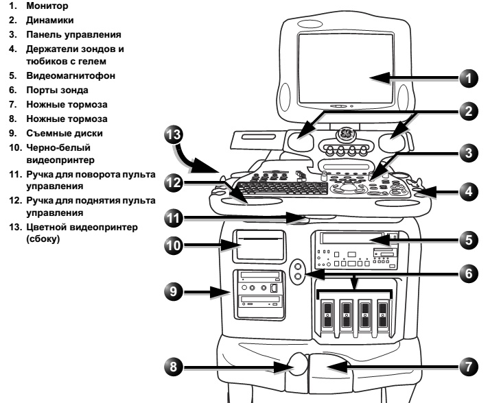
Полностью цифровая универсальная ультразвуковая диагностическая система экспертного класса, разработанная на основе архитектуры TruScan.
Уникальные аппаратные и программные возможности, обеспечивающие непревзойденное качество визуализации и большие возможности обработки и анализа данных, делают систему уникальным диагностическим инструментом для исследований сердечно-сосудистой системы.
Vivid 7 Dimension является первой ультразвуковой диагностической системой с мультиплановой визуализацией и четырехмерной реконструкцией сердца в реальном масштабе времени, интегрированными в платформу TruScan Raw Data.
Области применения УЗИ VIVID 7
- Кардиология.
- Ангиология.
- Транскраниальные исследования сосудов головного мозга.
- Близко расположенные органы и поверхностные структуры.
- Органы брюшной полости.
- Акушерство, гинекология.
- Педиатрия, неонатология.
- Скелетно-мышечная система.
- Урология.
- Интраоперационные исследования.
Панель управления УЗИ аппарата VIVID 7
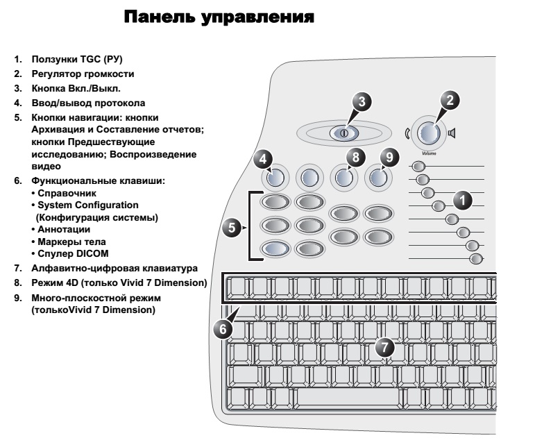
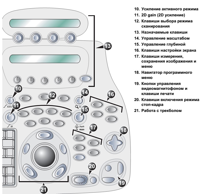
Экран сканирования VIVID 7 GE
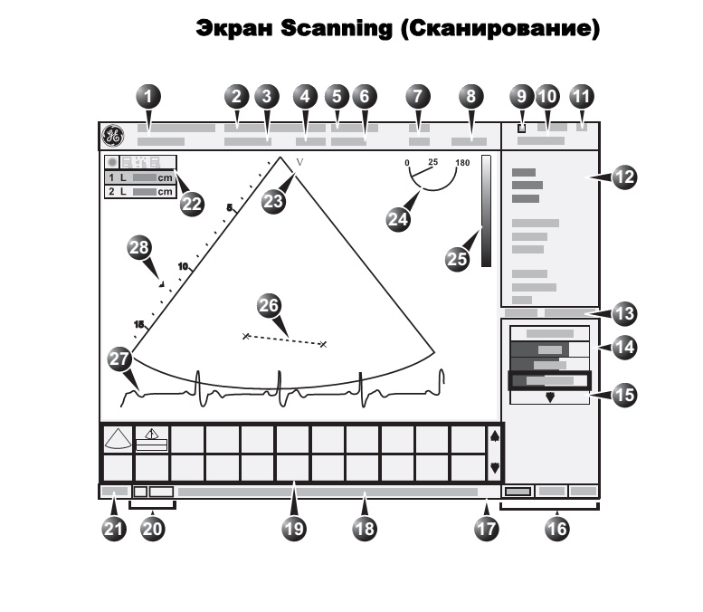
1. Текущие данные о пациенте
2. Учреждение
3. Дата и время
4. ID оператора
5. Зонд
6. Применение
7. Механический и тепловой индекс
8. Счетчик видеомагнитофона (воспроизведение)
9. Состояние видеомагнитофона
10. Дата и время
11. Сердечный ритм
12. Окно параметров
13. Счетчик кадров и таймер
14. Окно программного меню
15. Выпадающее программное меню
16. Назначение функций трекбола
17. Строка состояния
18. Приглашение/информация о состоянии
19. Рабочий планшет
20. Сервис и iLinq (для использования в следующих версиях)
21. Заглавные Вкл/Выкл
22. Таблица Measurement result (Результат измерения) (режим измерения)
23. Маркер ориентации зонда
24. Индикатор плоскости сканирования (для TE зонда)
25. Шкала оттенков серого/цветовая шкала
26. Измерение
27. Физиологичесие кривые(ЭКГ, Фоно, Дыхание)
28. Зона фокуса и шкала глубин
Алфавитно-цифровая клавиатура
- F1 — Отображение онлайн-версии руководства пользователя.
- F2 — Отображение диалогового окна настройки.
- F4 — Отображение окна DICOM spooler (Спулера
DICOM). - F6 — Отображение маркеров тела.
- F7 — Удаление аннотаций.
- F8 — Активизация курсора для выделения одной из аннотаций с целью ее удаления из изображения.
- F9 — Отображение стрелки.
- F10 — Позволяет вставить текстовую аннотацию в изображение в двух уровнях.
- Клавиша Text — Помещает заданную аннотацию в изображение.
Подключение и отключение зондов
Системы с опцией 4D имеют один порт для зонда нового типа.
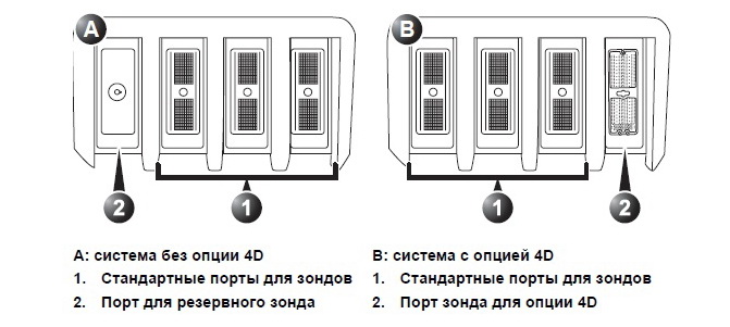
Подключение зондов
1. Возьмите разъем зонда вертикально кабелем вверх.
2. Поверните запорную ручку разъема до горизонтального положения.
3. Осторожно вставьте разъем в порт зонда.
4. Поверните запорную ручку до полностью вертикального положения, чтобы зафиксировать разъем.
5. Расположите кабель зонда так, чтобы он не касался пола.
Отключение зондов
1. Поверните запорную ручку против часовой стрелки до горизонтального положения, чтобы разблокировать разъем.
2. Выньте разъем.
3. Перед укладкой зонда в футляр для хранения убедитесь, что головка зонда очищена.
Настройка ЖК-монитора
ЖК-монитор можно поворачивать и изменять его наклон. Перед переносом или транспортировкой системы обязательно заблокируйте ЖК-монитор.
Поворот ЖК-монитора УЗИ VIVID 7
Захватите корпус ЖК-монитора с правого, и левого боков и поверните монитор в нужное положение. ЖК-монитор необходимо разблокировать.
Изменение наклона ЖК-монитора
Захватите корпус ЖК-монитора снизу и сверху и установите монитор в нужное положение, наклонив его вверх или вниз.
Блокировка/разблокировка ЖК-монитора
Кронштейн монитора вращается вокруг своей основной оси и на шарнире.
Блокировка ЖК-монитора
1. Сдвиньте кнопку блокировки на основании кронштейна
в положение блокировки. Двигайте кронштейн, пока он не зафиксируется на месте.
2. Сдвиньте кнопку блокировки на шарнире кронштейна в
положение блокировки. Двигайте кронштейн, пока он не зафиксируется на месте.
Разблокировка ЖК-монитора
1. Сдвиньте кнопку блокировки на основании кронштейна в свободное положение.
2. Сдвиньте кнопку блокировки на шарнире кронштейна в свободное положение.
Скачать инструкцию на УЗИ GE Vivid 7
Скачать инструкцию и другую документацию на УЗИ аппарат GE Vivid 7 можно здесь.
Руководство пользователя ( user manual ) GE Vivid 7 скачать.
Сервисная инструкция ( service manual ) GE Vivid 7 скачать.
Регистрационное удостоверение GE Vivid 7 скачать.
Так же смотрите УЗИ аппарат LOGIQ S8 GE.