
В дилерской базе по ремонту и техническому обслуживанию грузовиков и автобусов Volvo Impact представлены: каталог запчастей грузовых автомобилей Volvo, руководства по ремонту, обслуживанию, диагностике, спецификации, сервисные бюллетени, нормочасы, расшифровка диагностических кодов неисправностей и инструмент для грузовиков и автобусов Volvo для европейского рынка.
- Издательство: Volvo
- Актуальность: 06/2016
- Система: Windows
- Интерфейс: Многоязычный (русский присутствует)
- Формат: ISZ
- Размер: 31,1 Gb
В дилерской базе по ремонту и техническому обслуживанию грузовиков и автобусов Volvo Impact представлены: каталог запчастей грузовых автомобилей Volvo, руководства по ремонту, обслуживанию, диагностике, спецификации, сервисные бюллетени, нормочасы, расшифровка диагностических кодов неисправностей и инструмент для грузовиков и автобусов Volvo для европейского и американского рынков. Отсутствуют модели старше 2006 года выпуска (они есть в Volvo Impact 2016).
- Издательство: Volvo
- Актуальность: 11/2018
- Система: Windows
- Интерфейс: Многоязычный (русский присутствует)
- Формат: ISO
- Размер: 57,4 Gb

Схемы на английском языке электрооборудования грузовых автомобилей Volvo FH12/FH16 с левым рулем.
- Автор: —
- Издательство: Volvo Truck Corporation
- Год издания: 1998
- Страниц: 128
- Формат: PDF
- Размер: 3,6 Mb
Схемы на английском языке электрооборудования грузовых автомобилей Volvo FM.
- Автор: —
- Издательство: Volvo Truck Corporation
- Год издания: —
- Страниц: 270
- Формат: PDF
- Размер: 20,3 Mb
Руководство по ремонту грузовых автомобилей Volvo F12 1979-1987 годов выпуска.
- Автор: —
- Издательство: СпецИнфо
- Год издания: —
- Страниц: 104
- Формат: —
- Размер: —
Руководство по техническому обслуживанию и ремонту грузовых автомобилей Volvo FE/FL с 2006 года выпуска.
- Автор: —
- Издательство: Диез
- Год издания: —
- Страниц: 504
- Формат: —
- Размер: —
Руководство по эксплуатации, техническому обслуживанию и ремонту + каталог запчастей грузовых автомобилей Volvo FH12.
- Автор: —
- Издательство: Диез
- Год издания: —
- Страниц: 392
- Формат: —
- Размер: —
Руководство по техническому обслуживанию и ремонту грузовых автомобилей Volvo FH12 1993-2005 годов выпуска.
- Автор: —
- Издательство: Диез
- Год издания: —
- Страниц: 416
- Формат: —
- Размер: —
Руководство по ремонту грузовых автомобилей Volvo F10 и Volvo FL10 с 1988 года выпуска.
- Автор: —
- Издательство: Терция
- Год издания: —
- Страниц: 164
- Формат: —
- Размер: —
Руководство по техническому обслуживанию и ремонту грузовых автомобилей Volvo FH и Volvo FM с 9- и 13-литровыми двигателями.
- Автор: —
- Издательство: Диез
- Год издания: —
- Страниц: 432
- Формат: —
- Размер: —
Руководство по ремонту грузовых автомобилей Volvo FH и Volvo FM с 9- и 13-литровыми двигателями.
- Автор: —
- Издательство: Диез
- Год издания: —
- Страниц: 480
- Формат: —
- Размер: —
Руководство по ремонту грузовых автомобилей Volvo FH и Volvo FM до 2005 года выпуска.
- Автор: —
- Издательство: Диез
- Год издания: —
- Страниц: 464
- Формат: —
- Размер: —
Руководство по эксплуатации, техническому обслуживанию и ремонту грузовых автомобилей Volvo VN/VHD 2002-2007 годов выпуска.
- Автор: —
- Издательство: Диез
- Год издания: —
- Страниц: 432
- Формат: —
- Размер: —
Руководство по эксплуатации, техническому обслуживанию и ремонту грузовых автомобилей Volvo VNL/VNM 1996-2002 годов выпуска.
- Автор: —
- Издательство: Диез
- Год издания: —
- Страниц: 336
- Формат: —
- Размер: —
Мультимедийное руководство на английском языке по техническому обслуживанию и ремонту грузовых автомобилей Volvo VN/VHD 1996-2002 годов выпуска.
- Автор: —
- Издательство: Volvo Truck Corporation
- Год издания: 2004
- Страниц: —
- Формат: ISO
- Размер: 297,8 Mb
Мультимедийное руководство на английском языке по техническому обслуживанию и ремонту грузовых автомобилей Volvo VN/VHD 2002-2004 годов выпуска.
- Автор: —
- Издательство: Volvo Truck Corporation
- Год издания: 2004
- Страниц: —
- Формат: ISO
- Размер: 112,7 Mb

Руководство по ремонту грузовых автомобилей Volvo F16/TF16.
- Автор: —
- Издательство: Терция
- Год издания: —
- Страниц: 128
- Формат: —
- Размер: —

Руководство по ремонту грузовых автомобилей Volvo FM9.
- Автор: —
- Издательство: Терция
- Год издания: —
- Страниц: 208
- Формат: —
- Размер: —

Руководство по ремонту эксплуатации и ремонту грузовых автомобилей Volvo FH с 2012 года выпуска с дизельными двигателями объемом 12,8/16,1 л.
- Автор: —
- Издательство: Монолит
- Год издания: —
- Страниц: 442
- Формат: —
- Размер: —
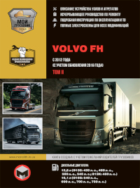
Руководство по ремонту эксплуатации и ремонту грузовых автомобилей Volvo FH с 2012 года выпуска с дизельными двигателями объемом 12,8/16,1 л.
- Автор: —
- Издательство: Монолит
- Год издания: —
- Страниц: 592
- Формат: —
- Размер: —

Руководство по техническому обслуживанию и ремонту грузовых автомобилей Volvo FE/FL/FL6 с 2000 года выпуска.
- Автор: —
- Издательство: Атласы автомобилей
- Год издания: —
- Страниц: 1232
- Формат: —
- Размер: —

Руководство по эксплуатации, техническому обслуживанию и ремонту грузовых автомобилей Volvo FH с 2002 года выпуска.
- Автор: —
- Издательство: Арго-Авто
- Год издания: —
- Страниц: 1240
- Формат: —
- Размер: —
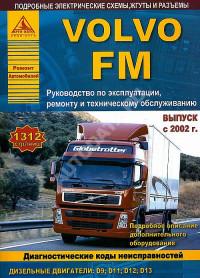
Руководство по эксплуатации, техническому обслуживанию и ремонту грузовых автомобилей Volvo FM с 2002 года выпуска.
- Автор: —
- Издательство: Арго-Авто
- Год издания: —
- Страниц: 1312
- Формат: —
- Размер: —
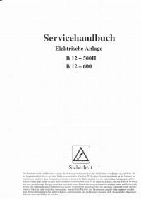
Схемы на немецком языке электрооборудования автобусов Volvo B 12.
- Автор: —
- Издательство: —
- Год издания: —
- Страниц: 95
- Формат: PDF
- Размер: 37,1 Mb
Руководство по техническому обслуживанию грузовых автомобилей Volvo серий AC/VN/WG/WX.
- Автор: —
- Издательство: Терция
- Год издания: —
- Страниц: 112
- Формат: —
- Размер: —
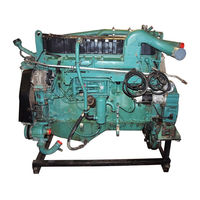
Руководство на испанском языке с описанием конструкции двигателя модели D9A грузовых автомобилей Volvo FM.
- Автор: —
- Издательство: —
- Год издания: —
- Страниц: 54
- Формат: PDF
- Размер: 16,9 Mb
Руководство по эксплуатации и техническому обслуживанию грузовых автомобилей Volvo VNL/VNM.
- Автор: —
- Издательство: Терция
- Год издания: —
- Страниц: 252
- Формат: —
- Размер: —
Руководство по эксплуатации и ремонту грузовых автомобилей Volvo FL6
- Автор: —
- Издательство: Терция
- Год издания: —
- Страниц: 164
- Формат: —
- Размер: —
Руководство по эксплуатации и техническому обслуживанию автобусов Volvo B 10 M 1986-1992 годов выпуска.
- Автор: —
- Издательство: Терция
- Год издания: —
- Страниц: 113
- Формат: —
- Размер: —
Руководство по эксплуатации и техническому обслуживанию грузовых автомобилей Volvo FH/FM.
- Автор: —
- Издательство: Терция
- Год издания: —
- Страниц: 260
- Формат: —
- Размер: —

- Manuals
- Brands
- Volvo Manuals
- Trucks
ManualsLib has more than 62 Volvo Trucks manuals
Click on an alphabet below to see the full list of models starting with that letter:
A
C
D
F
G
L
N
S
V
X
Popular manuals

100 pages
VNL Service Manual
353 pages
VNL Operator’s Manual

967 pages
FM Driver’s Handbook Manual
457 pages
VN Operator’s Manual
257 pages
FM Series Wiring Diagram
145 pages
FL6 Service Manual

205 pages
L90E Operator’s Manual
111 pages
FH Service Manual

660 pages
FM Handbook

129 pages
FH12 LHD Wiring Diagram
48 pages
D12 Service Manual

68 pages
VN 2003 Service Manual
83 pages
VNL Service Manual

36 pages
FL Product Manual
11 pages
A30D Service & Repair Manual
244 pages
FM Series Wiring Diagram
242 pages
FM 2 Series Service Manual
72 pages
VN Series Service Manual
19 pages
VN Service Bulletin
104 pages
VN Service Manual
Models
Document Type
A
A30D

Service & Repair Manual
A35E FS
Operator’s Manual • Manual
A60H
Manual
C
C 303
Manual
C 304
Manual
C 306
Manual
D
D12
Installation Manual • Service Manual • Operator’s Manual
D12A
Service Manual
D12B
Service Manual
D12C
Service Manual
D7 series
Installation Manual • Operator’s Manual
F
FH
Driver’s Handbook Manual • Service Manual • Handbook
FH 2 Series
Service Manual
FH Series
Wiring Diagram
FH VAL-BAS4
Wiring Diagram
FH12 LHD
Wiring Diagram
FH16 LHD
Wiring Diagram
FL
Product Manual
FL6
Service Manual
FM
Driver’s Handbook Manual • Handbook
FM 2 Series
Service Manual
FM Series
Wiring Diagram • Wiring Diagram
G
Group 655-601
Service Manual
L
L120E
Operator’s Manual
L90E
Operator’s Manual
N
NH
Service Manual
NH12 Series
Service Manual
NH12 VERSION2
Wiring Diagram
S
Symptom D12D US02
Service Manual
Symptom D16D US04
Service Manual
V
VAH 2013
Operator’s Manual
VAL-CHD2
Wiring Diagram
VHD
Operator’s Manual • Service Bulletin • Service Manual • Service Manual • Service Manual • Service Manual
VHD 2001
Operator’s Manual
VHD 2002
Service Manual
VHD 2003
Service Manual
VHD 2013
Operator’s Manual
VN
Service Bulletin • Operator’s Manual • Service Manual • Service Manual • Service Manual • Service Manual
VN 2002
Service Manual
VN 2003
Service Manual
VN 2013
Operator’s Manual
VNL
Operator’s Manual • Service Manual • Service Manual
VNL 300 Daycab
Operator’s Manual
VNL 430
Operator’s Manual
VNL 630
Operator’s Manual
VNL 670
Operator’s Manual
VNL 730
Operator’s Manual
VNL 780
Operator’s Manual
VNL42
Operator’s Manual
VNL42T
Operator’s Manual
VNL64
Operator’s Manual
VNL64T
Operator’s Manual
VNM
Operator’s Manual • Service Manual • Service Manual
VNM 200 Daycab
Operator’s Manual
VNM 430
Operator’s Manual
VNM 630
Operator’s Manual
VNM42
Operator’s Manual
VNM42T
Operator’s Manual
VNM64
Operator’s Manual
VNM64T
Operator’s Manual
VT
Service Bulletin
X
XPEDITOR Series
Operator’s Manual
Volvo Trucks
Руководство для водителя
Перед вами уникальное руководство для водителя, учитывающее номер шасси вашего грузового автомобиля и предпочитаемый вами язык. Руководство доступно в различных форматах и содержит только информацию, относящуюся к конфигурации вашего грузовика. Чтобы посмотреть онлайн-версию, нажмите приводимую ниже кнопку. Или выберите один из других вариантов.
Мобильное приложение
Вы можете загрузить руководство на свое мобильное устройство в виде приложения. Загрузите его через App Store (iOS) или Google Play (Android), затем введите свой уникальный номер шасси и предпочитаемый вами язык.
Формат PDF
Нажмите на ссылку ниже, чтобы загрузить свое собственное руководство для водителя в формате PDF. Информация приводится с учетом вашего уникального номера шасси, на предпочитаемом вами языке.
Встроенный дисплей
Кроме того, руководство водителя можно почитать в специальном приложении на встроенном дисплее вашего грузовика. Через него вы сможете получить доступ ко всем возможностям вашего автомобиля. Информация приводится на предпочитаемом вами языке.
Напечатанное руководство
Если вы потеряли свое руководство или хотите заказать новую версию на другом языке — обратитесь к своему дилеру. Он поможет вам разместить ваш заказ.

F86, FB86, N86, NB86 VOLVO Truck Service Manuals PDF

F88, FB88, G88 VOLVO Trucks Operator’s Handbooks & Maintenance Manuals PDF
FH12 & FH16 VOLVO Truck Service, Operator’s Manuals PDF & Electric Wiring Diagrams

VOLVO FM series Truck Operator’s Manual PDF

VOLVO FL series Truck Service Manual & EWD in PDF

VOLVO NH Service Manual PDF

VOLVO VHD, VH Truck Service Manual PDF

VOLVO VN, VNL & VNM Trucks Operator’s Manual PDF

VOLVO VT Truck Service Manual PDF
VOLVO Tractor & Excavator Manuals PDF
![]()
Volvo Tractor PDF Manual L150F L220F
Volvo Tractor PDF Manual L150F L220F
Volvo Tractor Manual L150F L220F.pdf
Adobe Acrobat Document
1.3 MB
![]()
Volvo Tractor PDF Manual L60F L120F
Volvo Tractor PDF Manual L60F L120F
Volvo Tractor Manual L60F L120F.pdf
Adobe Acrobat Document
1.5 MB
![]()
EDC Volvo b10 PDF Wiring Diagram
EDC Volvo b10 PDF Wiring Diagram
EDC Volvo b10 Wiring Diagram.pdf
Adobe Acrobat Document
60.0 KB
Some VOLVO Truck & Tractor PDF Service Manuals PDF, Electric Wiring Diagrams (F86, FB86, N86, NB86, F88, FB88, G88, FH12, FH16, FM,
FL, NH, VHD, VN, VT, VNM, L50F, L120F, L150F, L220F, VNL) are above the page.
Volvo Trucks Corporation was founded in 1920 as the automobile branch of the famous SKF bearing company.
The first in a series from April 1927 were running cars, and only in February 1928 with the plant rolled off the first 1.5-ton truck Volvo.
In 1998, Volvo plants, which employ 23 thousand. Man, produced 85 thousand. trucks over 6 tonnes and buses, ranking sixth in the world.
In the summer of next year, the company strengthened the already stable position by buying a 70% stake in the Swedish company Scania.
This paved the way education in the third world, the Volvo-Scania group, however, the spring of 2000, the EU Commission vetoed the agreement.
A few more months and a group of Volvo bought 100% of shares of Renault load compartment,
creating another major transnational concern for the production of trucks.
VOLVO bought SAMSUNG Heavy Industries.
Volvo E-Media Center
We offer additional resources you need to know your truck — and the road ahead. Below are the most common resources Volvo customers purchase.
Visit the Volvo eMedia Center

https://volvotrucks.vg-emedia.com/ProductListing.aspx?GroupId=504
Emissions Service Information Subscriptions
With a subscription to our online emissions service information tool, you can access current repair information for your engine, electrical system, and exhaust after-treatment system. Other details include system design, operation, component locations, and repair procedures following SIR standards set by the EPA and CARB.
Learn More

Find A Dealer
With our world-class dealer network of more than 430 locations, your trucks are never far from the quality care and maintenance you expect when you buy a Volvo truck.
Search the Network
- Manuals
- Brands
- Volvo Manuals
- Trucks
- VNL
- Operator’s manual
-
Contents
-
Table of Contents
-
Bookmarks
Quick Links
Operator’s Manual
VNL and VNM
Related Manuals for Volvo VNL
Summary of Contents for Volvo VNL
-
Page 1
Operator’s Manual VNL and VNM… -
Page 2
The National Highway Traffic Safety Administration (NHTSA) and Volvo Trucks North America, Inc. (VTNA) should be informed imme- diately if you believe that the vehicle has a defect that could cause a crash, injury or death. -
Page 3: Table Of Contents
Main Menu: Set-Up Mode ….132 Pre-Trip Inspection and Daily Mainte- Main Menu: System Diagnostic ..137 nance …………. 32 Main Menu: Data Log Mode (Volvo General ……….32 Engine Only) ……..152 Pre-Trip Inspection Quick List … 33 Main Menu: Password Input …. 158 Daily Maintenance ……
-
Page 4
Trailer Coupling Procedures ….. 323 Engine Start and Operation ….. 244 Trailer Uncoupling Procedures ..328 Starting the Engine ……244 Operating the Volvo Slider ….333 Cold Weather Start and Operation … 249 Emergency Information ….335 Engine Operation ……256 Towing Procedure …… -
Page 5
Warning Label Information IMPORTANT Before driving this vehicle, be certain that you have read and that you fully understand each and every step of the driving and han- dling information in this Operator’s Manual. Be certain that you fully understand and follow all safety warnings. It is extremely im- portant that this information is read and understood before the vehicle is operated. -
Page 6: General Information
If there are questions on the maintenance Establish a Preventive Maintenance Pro- and performance of your vehicle, please gram with the help of your local Volvo discuss them with your Volvo Truck dealer. Truck dealer. A Preventive Maintenance Your authorized dealer is required to have…
-
Page 7
It contains important operational and safety information that is needed by all drivers and owners of this vehicle. This Operator’s Manual covers Volvo VN- series vehicles manufactured by Volvo Trucks North America, Inc. with any of the following designations:… -
Page 8: General Safety Information
If so, you should contact an authorized Volvo Truck dealer to obtain those parts which best fit your own personal needs and preferences. WARNING All items within the cab must be secured before the vehicle is set in motion.
-
Page 9: Operating In Bobtail Mode
General Information Operating In Bobtail Mode Tractors are equipped with a bobtail air brake proportioning valve which automati- cally redistributes the braking force between front and rear axles when not hooked up to a semitrailer (bobtail operation). When operating in bobtail mode, the rear brake chambers receive reduced or propor- tional brake air pressure.
-
Page 10
General Information Do Not Overload This vehicle has been designed and assem- bled for a maximum gross vehicle weight rating (GVWR) and a maximum front and rear axle weights rating (FAWR and RAWR). The actual rating for this vehicle can be found on the label attached to the door frame on the driver’s side. -
Page 11: Reporting Safety Defects
Contact Volvo Trucks de Mexico by calling or by 01 (800) 90 94 900 writing to: Volvo Trucks de Mexico, S.A.
-
Page 12: Modifications To Vehicle
Drilling is permitted in the frame web in accordance with a specified hole spacing pattern. Consult a Volvo Truck dealer to obtain approved hole spacing dimensions or refer to the Frame Rail and Cross Member W7000519 Service Manual.
-
Page 13: Exhaust And Noise Emissions
General Information Exhaust and Noise Emissions General The Federal Clean Air Act, Section 203 (a) delivery of the vehicle to the ultimate pur- (3), states the following concerning the re- chaser, and, in addition, no manufacturer or moval of air pollution control devices or dealer may make take such action after sale modification of a certified engine to a non- and delivery of the vehicle to the ultimate…
-
Page 14
30 days. As the vehicle owner, you should also be aware that Volvo Trucks North America, Inc. may deny you warranty coverage if your vehicle or a part has failed due to abuse, neglect, improper maintenance or unapproved modifications. -
Page 15
first placed in service. The emission control system of your new Volvo engine was designed, built and tested us- ing genuine Volvo parts, and the engine is certified as being in conformity with Federal and California emission control regulations. -
Page 16
However, Volvo Trucks North America, Inc. may deny a warranty claim if your failure to perform required maintenance resulted in the failure of a warranted part. Receipts covering the performance of regular maintenance should be retained in the event questions arise con- cerning maintenance. -
Page 17
The following is a list of the items that are considered a part of the Emission Control Sys- tems and are covered by the Emission Warranty when installed as original equipment by Volvo Trucks North America, Inc. on vehicles which were built to conform to Environ- mental Protection Agency and California Air Resources Board regulations IMPORTANT — This may not include expendable maintenance items. -
Page 18: Noise Emissions
Volvo Trucks North America, Inc., which, at the time it left the control of Volvo Trucks North America, Inc. caused noise emissions to exceed Federal standards, are covered by…
-
Page 19
General Information Tampering with Noise Control System Federal law prohibits the following acts or the causing thereof: (1) The removal or rendering inoperative by any person, other than for purposes of maintenance, repair, or replacement, of any device or element of design incorporated into any new vehicle for the purpose of noise control prior to its sale or delivery to the ultimate purchaser or while it is in use;… -
Page 20
General Information Fuel System Removing or altering engine speed pro- gramming so as to allow engine speed to exceed manufacturer’s specifications. Inner Fender Shields and Cab Skirts Removing shields or skirts. Cutting away parts of shields, skirts or dam- aged or loose portions of shields or skirts. -
Page 21: Vehicle Data
General Information Vehicle Data Identification and Labels It is extremely important that the correct vehicle model and serial number are given whenever replacement parts or service liter- ature are ordered. Using these numbers, as well as giving the major component model and serial numbers, will prevent delay and errors in obtaining the correct material.
-
Page 22
W0001210 removed. If for any reason a label is dam- aged, contact your Volvo Truck dealer for a replacement. Noise Emission Control A Noise Emission Control label is located on the left end of the dash. -
Page 23
General Information Components The Volvo D12 engine serial number is lo- cated on the rear, left side of the cylinder block. There is also a label on the engine elec- tronic control unit that shows the engine serial number. W0001529… -
Page 24
General Information The rear axle model and serial number is located on the right side of the transfer gear housing on the tandem front axle. It is lo- cated on the left side of the differential housing on the tandem rear axle and on the right side of the single axle. -
Page 25: Vehicle Access
NOTE! The vehicle is delivered with 2 identical keys. If more keys are needed, order them through your Volvo Truck au- thorized dealer. The keys are laser cut and require a special machine for copying, available through the dealer. Record the key code and keep it in a secure place.
-
Page 26
Vehicle Access The door has a position lock that enables the door to remain open in two different positions. An indented bar is holding the door at approximately 30 and in the fully open position at approximately 85 . To close the door from the inside, place the hand in the handhold and pull the door in. -
Page 27: Cab Entry And Exit
Vehicle Access Cab Entry and Exit General WARNING Do not stand on the steps or any other Both the operator and passenger should part of the vehicle while it is in motion. exercise caution when entering or exiting The steps and the back of cab access the cab.
-
Page 28: General Entry Guidelines
Vehicle Access General Entry Guidelines box cover is properly fastened before stepping. Always have three limbs (one foot and two hands or two feet and one hand) Do not jump from the cab or from the in contact with the vehicle at all times steps to the ground.
-
Page 29
Vehicle Access Driver Side Entry/Exit Open the door. Place any hand-carried items on the cab floor. Grasp the right grab handle with your right hand and the left grab handle with your left hand. Put your right foot fully on the bottom step and pull yourself up to the opening. -
Page 30
Vehicle Access Behind the Cab Entry When trailer air and electrical connections can not be coupled from the ground, Fed- eral Regulations require commercial carriers to provide back-of-cab access steps, grab handles and plates. Depending on what option is chosen, grab handles are available in many variations. -
Page 31: Entering Sleeper From Seat
Vehicle Access Stand on the ground when connecting the air and electrical connections to the trailer. W5000713 Entering Sleeper From Seat Standard Gear Lever When moving from the driver seat to the sleeper section, follow this procedure: • Make sure the parking brakes are set •…
-
Page 32
Vehicle Access Folding Gear Lever (option) When moving from the driver seat to the sleeper section, follow this procedure: • Make sure the parking brakes are set • To release the gear lever, pull the lever toward the seat and press on the knob downward in a straight line. -
Page 33
Vehicle Access • If equipped with an adjustable steering column, move the steering wheel up and forward • Place the left hand on the steering wheel and the right hand on the top of the dash • Move the right foot out to the middle of the floor •… -
Page 34: Luggage Compartment
Vehicle Access Luggage Compartment To gain access to the luggage compart- ments, there is a pull-ring connected to the lock, located at the lower rear corner of the cab door opening on each side. Pull ring to unlock the door. The lock has a safety catch that will hold the door in place, even if the door is not fully locked.
-
Page 35: Hood
Vehicle Access Hood The hood is locked down by two latches, one on each side of the back end of the hood. The latches are operated by a handle on the bottom edge of the dashboard. Pull the bottom of the handle out to release hood.
-
Page 36
Vehicle Access Manual Hood Opening In the event of a malfunction in the hood opening mechanism, the hood latches can be manually operated through an opening in the wheelwell splash shield. The opening is normally covered by a plate. To access the opening, remove the two screws using a T30 Torx screwdriver. -
Page 37: Pre-Trip Inspection And Daily Maintenance
Service Manuals or Section 49 CFR 396.13 states that all motor contact a Volvo Truck dealer for the correct carrier drivers must complete a written re- procedures, specifications and intervals. port at the end of each work day for each…
-
Page 38: Pre-Trip Inspection Quick List
Pre-Trip Inspection and Daily Maintenance Pre-Trip Inspection Quick List W0001230 Inspect the vehicle in a circular manner as shown in the illustration. Numbers between parentheses in the list, re- fer to pages in this manual where component function and necessary inspection is explained in greater detail. Approaching the Vehicle Step 1: Left Side Of the Cab •…
-
Page 39
Pre-Trip Inspection and Daily Maintenance Step 1: Left Side Of the Cab (cont.) Lights and Reflectors Left Front Brake • Lower hood and inspect parking, clearance and identification lights on • Condition of brake drum. With brakes hood and cab. They should be clean, released, look for a noticeable gap be- operating and of the proper color. -
Page 40
Pre-Trip Inspection and Daily Maintenance W0001230 Step 3: Right Side Of Cab Area (cont.) Under Hood, Right Side Right Front Suspension • Check condition of coolant and heater hoses. • Check condition of spring, spring hangers, shackles, U-bolts: no cracks, •… -
Page 41
Pre-Trip Inspection and Daily Maintenance Condition of Visible Components Suspension • • Check condition of springs (leaf or Rear of engine: not leaking. air), spring hangers, shackles and U- • Transmission: not leaking. If equipped bolts. with oil cooler, check for leaks or that •… -
Page 42
Pre-Trip Inspection and Daily Maintenance W0001230 Step 7: Coupling System Area Step 8: Left Saddle Tank and Left Rear Vehicle Wheels Area Fifth Wheel Dual Wheels, One Or Two Axles • Securely mounted to the frame. • Check condition of wheels and rims. Especially look for cracks, missing •… -
Page 43
Pre-Trip Inspection and Daily Maintenance Brakes Left Fuel Tank(s) • • Condition of brake drums. With brakes Securely mounted and not damaged or released, look for a noticeable gap be- leaking. tween lining and drum (This check • Fuel lines secure and not leaking. cannot be made if dust covers are in Check that shut-off valves are open. -
Page 44
Pre-Trip Inspection and Daily Maintenance W0001230 In the Cab • • Check steps and grab handles for Check climate control and defroster looseness or breakage ( page 23). ( page 174). If equipped, check mirror Also, clean them if there is any sub- heater. -
Page 45
Pre-Trip Inspection and Daily Maintenance Hooking Up To Trailer Hook-up Preparation • Check kingpin and mounting plate on trailer, free from wear, bends or dam- age. • Chock trailer wheels. Fifth Wheel Or Trailer Hitch • No visible space between fifth wheel and trailer ( page 326). -
Page 46
Pre-Trip Inspection and Daily Maintenance W0001361 NOTE! Refer to the trailer manufacturer’s manual for specific information on the trailer checks. Step 9: Trailer Front Area Spare Wheel(s) Air and Electrical Connections • Carrier or rack not damaged. • Glad hands properly mounted, free •… -
Page 47
Pre-Trip Inspection and Daily Maintenance Step 11: Right Rear Trailer Wheel tween lining and drum (This check cannot be made if dust covers are in Dual Wheels, One Or Two Axles place). • Check condition of wheels and rims. • Condition of brake hoses: check for Especially look for cracks, missing any chafing. -
Page 48
Pre-Trip Inspection and Daily Maintenance W0001361 NOTE! Refer to the trailer manufacturer’s manual for specific information on the trailer checks. • Step 13: Left Rear Trailer Wheels Area If equipped with sliding axles, check position and alignment. Look for dam- Dual Wheels, One Or Two Axles aged, worn or missing parts, all locks present, fully in place and locked. -
Page 49
Pre-Trip Inspection and Daily Maintenance Step 14: Left Side of Trailer Area Before Leaving the Parking Area • Landing Gear or Dolly Area Remove chocks from the wheels. • • Fully raised; no missing or damaged Test trailer hook-up by slowly pulling parts. -
Page 50: Daily Maintenance
Pre-Trip Inspection and Daily Maintenance Daily Maintenance The following should be checked daily in addition to doing the pre-trip inspection of the truck or tractor and trailer. Before working on or inspecting a vehi- cle, set the parking brakes, place the While checking the fluid levels, visually in- transmission in neutral and block the spect hoses, pipes and their connections for…
-
Page 51
W2002047 See the “Operator’s Manual, Maintenance and Engine” for correct types of oil used in Volvo engines. To add oil to the engine, remove oil cap on the valve cover and fill through the hole. CAUTION Make sure the oil added is the same type of oil that is in the engine. -
Page 52
Pre-Trip Inspection and Daily Maintenance Check fluid level in the clutch fluid reser- voir. Fluid level should be between the level marks on the reservoir. If fluid needs to be added, use brake fluid, DOT 4. W4000726 Check level in the windshield washer reser- voir. -
Page 53
NOTE! Make sure that all fluid levels are at their proper levels. If the fluids are not at their proper levels, add as necessary. Refer to the Engine and Maintenance Manual for information on what types of fluids are rec- ommended for your Volvo vehicle. -
Page 54
Pre-Trip Inspection and Daily Maintenance WARNING When draining the air tanks, do not look into the area of the draining air. Dirt or sludge particles may be in the air stream that could cause eye injury. Empty out the air tanks daily. With the air system fully charged and with the engine shut off, listen for air leaks. -
Page 55: Additional Safety Features
Additional Safety Features Safety Belts General Safety belts must be properly worn at all times by the driver and all passengers while the vehicle is in motion even if the vehicle is equipped with a Supple- mental Restraint System (SRS or air bag).
-
Page 56
Additional Safety Features Safety belts must be worn by the driver and all passengers at all times. Before adjusting or fastening the safety belt, move the seat forward or rearward and adjust the seat height as necessary. Sit erect and adjust the seat cushion and seat back for a comfort- able driving position. -
Page 57
Additional Safety Features Operating the Safety Belt To fasten the safety belt, pull the belt out from the retractor and insert the latch into the buckle. Verify proper lock of the latch by pulling on the latch. Adjust the slack by pulling on the top part of the belt until the lower part, or the part that crosses the lap, is snugly adjusted. -
Page 58
Additional Safety Features Sleeper Safety Restraint Always use the safety restraint when the vehicle is in motion. Failure to do so not only may cause severe injuries or death to the passenger in the event of an acci- dent but also poses a danger of injuries to other occupants of the vehicle. -
Page 59
Additional Safety Features Safety Restraint — VN-420, VN–610 and VN–660 The restraint has latches in one end and buckles in the other so it can only be in- stalled one way. Connect the restraint to the back wall and the buckles on the floor. Con- nect the side tethers and adjust the straps to form a “tent”… -
Page 60
Additional Safety Features Inspection Check the belts, buckles, latch plates, re- tractors, anchorages, and guide loops to ensure that they are working properly. Look Failure to properly inspect and maintain for loose/damaged parts (without disassem- the safety belts can cause serious per- bling) that could keep the restraint system sonal injury or death. -
Page 61
Additional Safety Features The following maintenance guidelines de- tail how to inspect safety belts and tethers for cuts, fraying, extreme or unusual wear of the webbing, etc., and damage to the buckle, retractor, hardware or other factors which indicate that safety belt system re- placement is necessary. -
Page 62
Additional Safety Features Check to make sure that the D-loop web guide is rotating properly. If the guide is not rotating properly, the webbing will pull at the wrong angle through the guide, ac- celerating wear. W8002477 If equipped, check the comfort clip for cracks or possible damage. -
Page 63
Additional Safety Features The retractor web storage device is mounted on the B-pillar, just behind the door in the cab. The retractor is the heart of the safety belt system and can be damaged if abused, even unintentionally. Check the retractor web storage device operation to ensure that it is not locked and that it spools out and retracts the webbing properly. -
Page 64
Volvo original re- with the vehicle seat or other parts of the placement safety belt. See your authorized cab structure, and the potential exposure of Volvo Truck dealer for replacement. -
Page 65
Additional Safety Features Comfort Clip Operation When provided, the comfort clip is located on the shoulder strap just below the D-ring. When adjusting the comfort clip, the fol- lowing procedure must be followed for proper adjustment: Pull out only enough webbing to allow slight pressure to the shoulder and chest. -
Page 66: Srs Airbag
The Volvo SRS Airbag provides increased protection in frontal collisions, where the vehicle collides with a fixed or heavy object with enough force to activate the sensors which then activates the airbag.
-
Page 67: Srs System
Additional Safety Features SRS System The inflatable airbag is folded into the cen- ter of the steering wheel. It inflates in the event of a serious collision above a certain level, where the angle of impact, crash severity, speed and nature of the object in- volved in the collision all play a part in whether or not the airbag is activated.
-
Page 68
If a problem develops in the system, the INFO telltale will come on together with the SRS telltale. CAUTION The vehicle should be taken to an autho- rized Volvo Truck dealer immediately if the SRS telltale stays on or lights up when the vehicle is being driven. -
Page 69
Additional Safety Features Warning Labels The label attached to the left hand sunvisor shows the year and month when a Volvo Truck dealer should be contacted for a specific inspection and for a possible re- placement of the airbag. This is done to guarantee the function of the airbag after the stated date. -
Page 70
Additional Safety Features Any queries concerning the SRS system should be directed to a Volvo Truck dealer. There is no maintenance required for the SRS system until the date stated on the warning label located on the left hand sun- visor. -
Page 71
If the airbag has de- ployed, the following is recommended: • Have the vehicle towed to a Volvo Truck dealer. Even if the vehicle can be driven after a collision, it is not recommended to drive the truck with the airbag deployed. -
Page 72
Heart of the Volvo safety system The three-point anchored safety belt is the heart of the Volvo safety system. The belt should be worn at all times. The SRS system is intended as a supplement to the three-point anchored safety belt. -
Page 73: Safety Equipment
Additional Safety Features Safety Equipment Safety triangles and fire extinguishers are available as optional equipment. The fire extinguisher should be located by the base of the driver seat, between the seat and the door. Depending on the cab style, the safety triangles are located in different places in the cab.
-
Page 74: Vorad Collision Warning System
Additional Safety Features VORAD Collision Warning System The Eaton VORAD computerized Collision Warning System constantly monitor vehi- cles ahead with a front end mounted radar and in a blind spot area with an optional side mounted radar. The Collision Warning System warns the driver of potentially dan- gerous situations by activating visual and audible alerts.
-
Page 75: Instruments And Controls
Instruments and Controls Dash Overview W8002383 Air Vents ( page 182) 11 Ashtray Diagnostic Test Connection 12 Instrument Cluster, Left ( page 74) Left Switch Cluster ( page 99) 13 Instrument Cluster, Main ( page 82) Headlight Switch ( page 104) 14 Instrument Cluster, Right ( page 89) Driving/Fog Lights — option ( page 105) 15 Trailer Hand Brake Control ( page 283)
-
Page 76: Instrument Cluster Overview
Instruments and Controls Instrument Cluster Overview W3004396 General Center Section The center section contains tachometer, The cluster is available in seven different speedometer and odometer. See page 82 for configurations, with the speedometer either gauge information. In the lower part there graded in mph or km/h.
-
Page 77: Telltale Overview
Instruments and Controls Telltale Overview W3004406 Engine Preheat ( page 78) 13 Trailer ABS ( page 88) Yellow INFO Light 14 Air Suspension Level ( page 79) ( page 88) STOP Light 15 Mirror Heater ( page 88) ( page 80) 16 Right Turn ( page 86) No Charge ( page 81) 17 Transmission Temperature…
-
Page 78: Graphic Display Telltale Overview
Instruments and Controls Graphic Display Telltale Overview W3003534 Voltmeter ( page 162) 10 Coolant level ( page 126) Engine oil temperature ( page 159) 11 Washer fluid level ( page 120) Transmission oil temperature 12 Engine airfilter clogged ( page 121) ( page 125) 13 Too cold for engine brake ( page 289) Preheating active ( page 78)
-
Page 79: Left Instrument Section
Instruments and Controls Left Instrument Section Pyrometer (option) (this page) Engine Coolant Temperature ( page 75) Engine Oil Pressure ( page 76) Turbo Boost Pressure (option) ( page 77) Graphic Display ( page 114) Telltale Indicators ( page 77) W3003644 A —…
-
Page 80
The gauge indicates engine coolant temper- ature. Normal operating temperature reading is 165 to 205 F (75 to 95 C) for the VOLVO engine. The temperature, under normal driving conditions, must be below the red sector. The temperature range for… -
Page 81
Instruments and Controls C — Engine Oil Pressure The gauge indicates oil pressure by a sensor directly connected to the engine lubrication system. Normal oil pressure is 30 to 70 psi (210 to 480 kPa) when the engine is at nor- mal operating temperature. -
Page 82
Instruments and Controls D — Turbo Boost Pressure (option) The gauge indicates intake manifold pres- sure on the engine. The pressure is generated by the turbo. Boost pressure should be the same at a given engine tem- perature, speed and load. Turbo boost pressure will vary for different engines and vehicle models. -
Page 83
Instruments and Controls 1 — Engine Preheat Telltale The amber telltale will light up when the intake manifold preheater is operating. The heater is used for better cold starts. Opera- T3008841 tion time of the heater can vary in several steps from 0 to 50 seconds depending on coolant temperature and outside air temper- ature. -
Page 84
When ignition is switched on, the telltale goes out unless a defect is detected. NOTE! On vehicles equipped with a Volvo engine, the telltale is on for 3 to 5 seconds after the ignition key switch is turned on. -
Page 85
Instruments and Controls 3 — STOP Telltale Failure to take necessary action when STOP telltale is on, can ultimately result in automatic engine shutdown and loss of power steering assist. Vehicle crash resulting in personal injury or death can occur. STOP telltale lights up red to alert the operator that a severe problem has been detected and in some cases a preventive ac-… -
Page 86
Instruments and Controls 4 — No Charge Telltale The No Charge telltale lights up red when a problem exists in the charging system or when there is no output from the alternator, such as when the engine is not running. T3008832 The No Charge telltale lights up dimly when there are several volts difference be-… -
Page 87: Main Instrument Section
Instruments and Controls Main Instrument Section Tachometer ( this page) Speedometer ( page 83) Master Warning Telltale ( page 84) Warning Telltales ( page 85) W3003643 G — Tachometer The tachometer is electrically driven by a signal from the engine. Monitor the tachometer to guide correct gear shifting and to prevent engine overspeeding when descending steep grades.
-
Page 88
This is done by repro- gramming the engine or transmission electronic controller. Reprogramming can be performed by your authorized Volvo Truck dealer. The odometer is a Liquid Crystal Display (LCD) mounted in the lower speedometer face. -
Page 89
Instruments and Controls J — Master Warning Telltale The Master Warning Telltale and buzzer alerts of a dangerous situation. Air pres- sure is low and the remaining air volume may not be enough for repeated braking. The emergency brakes may engage, W3000638 causing a wheel lock-up, loss of vehicle control and become a hazard to follow-… -
Page 90
Instruments and Controls K — Warning Telltales, Center Section W3003646 Left Turn Telltale ( page 86) Anti-Lock Brake System (Tractor or Truck) Telltale ( page 88) Fifth Wheel Lock Telltale ( page 86) Anti-Lock Brake System (Trailer) Wheel Diff. Lock Telltale ( page 86) Telltale ( page 88) Interaxle Diff. -
Page 91
Instruments and Controls Left and Right Turn Telltales This lights up green when the turn signal is activated and blinks in time with the out- side turn signal lamps. An audible signal also sounds in time with the telltale. A sin- W3000903 gle short beep is heard when the telltale lights up. -
Page 92: Safety Belt Telltale
Instruments and Controls High Beam Telltale Any time the high beams are activated, by the high/low beam switch or the high beam flash switch, the telltale lights up blue. For information on switching high/low beam, see page 97. W3001303 Safety Belt Telltale The telltale lights up red each time the ig- nition is turned on to remind the driver to fasten the safety belt.
-
Page 93: Air Suspension Telltale
Instruments and Controls ABS Telltale, Tractor and Trailer The telltale lights up amber if the Anti- Lock Brake System (ABS) senses a problem under the following conditions: The system will go through its self test when the ignition switch is turned on and the telltale should continue to be on.
-
Page 94: Right Instrument Section
Instruments and Controls Right Instrument Section Forward Drive Axle Oil Temperature (option) ( this page) Rear Drive Axle Oil Temperature (option) ( this page) Fuel Level Gauge ( page 90) Application Air Pressure (option) ( page 90) Air Suspension Pressure (option) ( page 90) Front Brake System Air Pressure ( page 91)
-
Page 95
Instruments and Controls N — Fuel Level Gauge The gauge is connected to a sending unit in the fuel tank. There is only one sender even if the vehicle is equipped with dual tanks. W3003628 O — Application Air Brake Pressure (option) Air gauges are directly connected to the air brake system. -
Page 96
Instruments and Controls P & Q — Front and Rear Brake System Air Pressures The system air gauges are directly con- nected to the front and rear circuit tanks. The two gauges should register equal air pressure. Air brake system pressure should be between 90 to 135 psi (620 to 930 kPa) for normal operation. -
Page 97
Instruments and Controls R — Warning Telltales, Right Section Transmission Temperature (this page) Check Transmission (this page) Traction Control System ( page 93) W3004416 Wait to Start (Not used) Automatic Neutral ( page 94) Water in Fuel (Not used) Transmission Temperature Telltale The Transmission Temperature Telltale is for the Allison WTEC III transmission. -
Page 98
Instruments and Controls Traction Control System Telltale The amber telltale will blink only when the Traction Control System (TCS) mud/snow mode is engaged. At all other times, the TCS system operates in the background without indication. The system does not have an on/off switch. -
Page 99
Instruments and Controls Auto Neutral Telltale The Auto Neutral Telltale is for the Allison WTEC III transmission. The green indica- tor lights up when the transmission is in auto neutral. Auto neutral is activated just before the vehicle comes to a complete stop W3004308 (less than 1.5 mph [2.5 km/h]). -
Page 100: Changing Telltale Bulbs In Cluster
Instruments and Controls Changing Telltale Bulbs In Cluster NOTE! Before beginning to work, make sure the vehicle ignition is switched OFF. If possible, adjust the steering column back. Remove the two screws at the top of the instrument cluster and fold the cluster out and let it rest face-down against the steering column so the bulbs are accessible.
-
Page 101
Instruments and Controls A bulb change tool can be ordered from your Volvo Truck dealer under part number 1089953. Use only this tool to change bulbs in the instrument cluster. To remove bulb, insert tool onto the bulb assembly, rotate a 1/4 turn counterclock- wise and pull the bulb assembly out of the cluster. -
Page 102: Steering Column Switches
Instruments and Controls Steering Column Switches Turn Signal/Headlight Beam Change The turn signal is activated by the lever un- der the left side of the steering wheel. If the vehicle is equipped with a cruise con- trol, the controls for this are located on the turn signal lever.
-
Page 103
Instruments and Controls Windshield Wiper/Washer The wiper/washer functions are operated by the same switch. The wipers have a normal and a fast speed which are activated by moving the lever down one or two posi- tions. To let the wipers engage for one or two passes, lightly depress the lever until the wipers start and hold it there. -
Page 104: Left Switch Cluster
Instruments and Controls Left Switch Cluster This switch cluster has only one switch po- sition permanently filled. Other positions are for optional equipment. The standard switch is for the Hazard Lights. Other switches that can be located in this cluster are for Back of Cab Light, Head- light Flash, Dome Fluorescent Light in VN-660 &…
-
Page 105
Instruments and Controls Headlight Flash Switch (option) The headlight flash switch will momentar- ily turn the headlights off when pressed. The switch will return when released, turn- ing headlights on again. This switch functions when either of Daytime Running Lights or low beam headlights are on. W3002306 Sleeper Overhead Lighting, VN–770 This operates the fluorescent overhead… -
Page 106
Instruments and Controls Power Take Off There are two basic types of PTOs avail- able: engine mounted and transmission mounted. The transmission mounted PTO is clutch dependent, which means that opera- tion can be regulated by depressing or releasing the clutch pedal. This type of PTO should not be in use while driving. -
Page 107
Instruments and Controls Engine Mounted PTO The engine should be running at low idle and the vehicle should be stopped or run- ning at very low speed before engaging power take off. Engage the PTO by press- ing in the bottom part of the switch. The PTO is now in operation and hydraulic flow W3001993 can be regulated by the engine speed. -
Page 108: Pto Speed Adjustment
Instruments and Controls PTO Speed Adjustment Have the PTO engaged before adjusting the speed. For the PTO speed adjustment to function, the Cruise Control or idle adjust can not be active, brake and clutch pedals must be released, and vehicle speed must be under approximately 5 mph (8 km/h).
-
Page 109: Driving Light Switches
Instruments and Controls Driving Light Switches Headlights The headlight switch controls parking lights and headlights. It is a two position rotary switch, turning on parking lights, cab marker lamps and taillights in the first posi- tion and turning on headlights in the second position.
-
Page 110
Instruments and Controls Driving and Fog Lights (option) Combinations of driving and fog lights can be mounted in standard locations in the aerodynamic bumper or from the underside of the steel bumper. These are operated by a switch next to the headlight switch. Fog and driving lights are wired so they are turned on only when the headlight switch is on. -
Page 111: Right Switch Cluster
Instruments and Controls Right Switch Cluster This switch cluster can hold up to six optional equipment switches. Planned func- tions are Marker Interrupt, Traction Control (TCS), Exhaust or Engine Brake and Heated Mirrors. W3000972 Marker Interrupt Switch The switch interrupts power to the marker lights when held down.
-
Page 112
Instruments and Controls Exhaust/Engine Brake NOTE! It is normal for there to be a slight delay in the application of a vehicle speed retardation device. When using a device of When operating your tractor bob-tail this type, be sure to think ahead and ana- without a trailer or on slippery roads, lyze conditions in order to use the device the engine brake switch must be in the… -
Page 113
(1,500 to 2,300 r/min). For proper operation, see page 289. Engine Brake, Volvo Engine — Optional The Volvo Engine Brake (VEB) is a com- pression brake. It works together with the exhaust brake to provide two levels of braking power. -
Page 114
Instruments and Controls Heated Mirror Switch (option) The vehicle can be equipped with heated mirrors. The switch turns on an electric heater element that is a part of the mirror glass. The heater is self regulating and will keep a steady temperature after reaching operating temperature. -
Page 115: Pneumatic Switch Cluster
Instruments and Controls Pneumatic Switch Cluster The pneumatic switch cluster can have up to four optional equipment switches. They regulate air flow directly to the following equipment: Differential Lock-Wheel and Interaxle, Air Suspension Level and Fifth Wheel Slide. To prevent accidental engagement, each switch has a latch that needs to be pressed down before the switch can be operated.
-
Page 116
Instruments and Controls Suspension Level CAUTION The vehicle must never be driven with the air springs deflated. Damage to air suspension parts will occur if springs are not inflated properly. Tractors with rear air suspension have a W3001341 control for deflating the air springs. Use this when uncoupling from trailers. -
Page 117: Optional Switch Cluster
These should be located in the optional switch cluster and can be purchased from your local Volvo Truck dealer. W3002419 The optional switch panel can be removed and a radio or a Volvo Road Relay can be installed. W3002420…
-
Page 118: Miscellaneous Switches
Instruments and Controls Miscellaneous Switches Horn Switches Electric and air horns are standard equip- ment. They are both operated from the steering wheel. The air horn button (1) is located in the middle of the steering wheel. If the vehicle is equipped with an airbag (SRS), the airbag module can be pressed down anywhere around the edge to engage the air horn.
-
Page 119: Graphic Display
Graphic Display Graphic Display Overview T3010426 The display in the bottom left-hand corner The information which is accessible varies, of the instrument cluster presents opera- depending on whether the truck is in a tional information to the driver. The display driving or non-driving mode.
-
Page 120: Graphic Display Controls
Graphic Display Graphic Display Controls If the vehicle is in motion, use the dis- play controls carefully. Do not lose road concentration. Be familiar with operation of the controls. Shifting concentration to operating the controls can lead to losing control of the vehicle and may result in serious personal injury or death.
-
Page 121
Graphic Display Changing Settings The up/down buttons increase or re- ALARM 08:20 duce the set values (e.g. hours and minutes in the adjacent example). CLOCK 08:00 Pressing SELECT confirms the choice. If there are several settings to change in the same menu, the cursor is moved to the next setting using the up/down buttons (e.g. -
Page 122: Graphic Display Telltales
Graphic Display Graphic Display Telltales W3003534 Voltmeter ( page 162) 10 Coolant level ( page 126) Engine oil temperature ( page 159) 11 Washer fluid level ( page 120) Transmission oil temperature 12 Engine airfilter clogged ( page 121) ( page 125) 13 Too cold for engine brake ( page 289) Preheating active ( page 78) 14 Overheating, instrument cluster…
-
Page 123: Information And Stop Messages
Graphic Display Information and Stop Messages The information and stop messages work together with the INFO or STOP tell- tales below the Graphic Display. If the engine is running, the buzzer will sound at any time the STOP telltale comes on. Information Telltale NOTE! When the yellow INFO telltale…
-
Page 124: Information Telltale
Graphic Display Information Telltale General The yellow INFO telltale lights up when an abnormal status is detected by an elec- tronic control unit. A telltale or text, or T3008860 both, are shown in the display in addition to the INFO telltale. For certain telltales, a reference value is also shown.
-
Page 125
The airbag (SRS) is described on page 63. T3008842 CAUTION The vehicle should be taken to an autho- rized Volvo Truck dealer immediately if the SRS telltale stays on or lights up when the vehicle is being driven. Instrument Cluster Overheating The symbol is shown when the temperature behind the instrument cluster is too high. -
Page 126
T3008843 To replace air filter, see the Operator’s Manual, Maintenance and Engine. Too Cold for Engine Brake (Volvo Engine Only) Position 2 of the engine brake should not be switched on until the engine has become warm (over 110 F [45 C]). If position 2 is… -
Page 127: Charging System
Graphic Display Transmission Oil Temperature This telltale lights when the transmission oil temperature is too high. It is shown with a text information about the temperature. T3008831 See page 125 for more information. Charging System This telltale lights when there is a problem in the charging system.
-
Page 128
Graphic Display Text The yellow INFO telltale lights up and information text is shown on the display. The text contains information on where the fault has occurred as well as the type of fault (applies to the data link): Factory installed equipment: CHECK ENGINE NEXT STOP… -
Page 129
Graphic Display Data link broken: CHECK DATA LINK BROKEN T3008860 Not factory installed equipment: The following can be shown if equipment CHECK has been added by a customer and con- nected to the data link: ERROR IN MID (Message IDentifier) = controller MID 142 To find more information on the data link diagnostic function, see page 137. -
Page 130
Graphic Display Telltale + Text The yellow INFO telltale lights up and information text together with a value is shown on the display. The text contains in- formation on where the fault has occurred and the value will show how much above or below the limit the current conditions are: Transmission Oil Temperature If the transmission oil temperature becomes… -
Page 131: Stop Telltale
Graphic Display Stop Telltale In the event of a serious fault, the red STOP telltale lights up and the buzzer sounds (if the engine is on). In addition to STOP telltale, a symbol or text, or T3008861 both, are shown in the display. A reference value is also shown for certain telltales.
-
Page 132
Graphic Display Engine Oil Pressure Failure to take necessary action when STOP telltale is on, can ultimately W3003613 result in automatic engine shutdown and loss of power steering assist. Vehicle crash resulting in personal injury or death can occur. Bring the vehicle to a safe stop where the problem can be checked. -
Page 133
Graphic Display Text The red STOP telltale lights up and in- formation text flashes on the display. The buzzer sounds if the engine is running. The Failure to take necessary action when text includes information about where the STOP telltale is on, can ultimately fault has occurred: result in automatic engine shutdown and loss of power steering assist. -
Page 134
Graphic Display Telltale + Text The red STOP telltale lights up and in- formation text together with a value is shown on the display. The text contains in- formation on where the fault has occurred and the value will show how much above or below the limit the current conditions are: Warning, temperature transmission oil If the temperature of the transmission oil… -
Page 135: Acknowledge Information And Stop Messages
Graphic Display Acknowledge Information and Stop Messages By pressing Esc, the display with the fault message is reset and the graphic display re- turns to the same status as before the error T3008852 occurred. An acknowledged fault message is shown as a symbol on the right in the graphic display window.
-
Page 136
Graphic Display Recall An acknowledged fault message can be re- called, i.e. be shown on the graphic display again. MENU: FAULTS? SELECT confirms the choice of the menu FAULTS? The last acknowl- edged fault message is shown. If there is more than one message, a down ar- row is shown in the right-hand corner. -
Page 137: Main Menu: Set-Up Mode
Graphic Display Main Menu: Set-Up Mode The menu Set-up mode has 14 sub-menus where 6 are not protected by passwords and 8 are protected by passwords. • Language • Mi/ F/USgal or km/ C • Clock format • Contrast • Backlight •…
-
Page 138
Graphic Display Miles/ F/USgal or km/ C MENU: Set-up mode, Mi/ F/USgal or km/ C NOTE! If Miles and Fahrenheit are chosen, the fuel consumption is shown in US gal- lons. If kilometers and Celsius are chosen, the consumption is shown in liters. Select the menu Set-up mode, Mi/ F/USgal or km/ C and the fol- lowing diagram is shown on the… -
Page 139
Graphic Display Clock format MENU: Set-up mode, Clock format Select the menu Set-up mode, Clock AM/PM format and the following diagram is shown on the graphic display (with the 24 h particular setting highlighted): The up/down buttons move the cursor between the alternatives. -
Page 140
Graphic Display Backlight MENU: Set-up mode, Backlight NOTE! This setting affects the display Adjust lighting brightness when the headlights or parking lights are on. When the exterior lights are off, the brightness on the display is con- stant. The graphic display brightness is controlled by the dimmer rheostat setting (which also controls the other instrument cluster light- ing). -
Page 141
Graphic Display Night display MENU: Set-up mode, Night display Select the menu Night display and the Night display following diagram is shown on the display: Normal With the up/down buttons the setting Reverse switches between Normal and Re- verse. With the setting Normal the text is dark and the background light. -
Page 142: Main Menu: System Diagnostic
Graphic Display Main Menu: System Diagnostic The menu System diagnostic has 3 sub- menus which are not protected by a password, and 1 sub-menu which is pro- tected by a password. • Fault diagnostic • Cluster self test • Part number Password required: (see page 158) •…
-
Page 143
Graphic Display The up/down buttons are used to move the cursor in the list. SELECT confirms the selection of ECU or Reset all. During the time that each respective Data transfer ECU is being called, the display shows the text: in progress please wait No faults in the chosen system:… -
Page 144
Graphic Display Fault codes are shown If there is a fault code or codes the Engine following is shown, for example: Coolant temperature Identification of ECU Line 1: Value too high Line 2: Identification of parame- ter/component Active Line 3: Fault type identification ”… -
Page 145
MID 128 fault codes are shown with numbers: PID 110 MID: Identification of ECU FMI 0 PID: Identification of parameter PPID: Volvo unique identification Active of parameter SID: Identification of component PSID: Volvo unique identification of component FMI: Identification of fault type ”… -
Page 146
Graphic Display The arrow in the lower, right-hand corner is shown if there is more than one fault code. The up/down buttons move the cursor and the next fault code is shown. If the correct password has been entered, resetting can be done in Reset all, last in the list. -
Page 147
Graphic Display Time stamp To show the time when the fault code Numeric was set for the first and latest occasion respectively, press SELECT when the Text particular fault code is presented (does not apply to ABS brakes or SRS Time stamp airbag). -
Page 148
Graphic Display Common Fault Codes MID Messages Supported (with text) Description code Description Retarder inh status code Engine Idle shutdown status Transmission Road speed % Throttle pedal Instrument Engine oil pressure Cab Controller Boost pressure SRS (Airbag) Air inlet temperature Air inlet pressure Additional MID Messages (without text) -
Page 149
Graphic Display Common Description Transm. Description SID code SID code Controller #2 C1 solenoid valve Power contact device C2 solenoid valve Start enable solenoid C3 solenoid valve CC resume switch C4 solenoid valve CC set switch C5 solenoid valve CC enable switch C6 solenoid valve Clutch pedal switch Lockup solenoid valve… -
Page 150
Graphic Display Brake Description Description SID code code ABS snsr axle 1 L Data valid, but high ABS snsr axle 1 R Data valid, but low ABS snsr axle 2 L Data erratic ABS snsr axle 2 R Voltage shorted high ABS snsr axle 3 L Voltage shorted low ABS snsr axle 3 R… -
Page 151
Graphic Display PPID (Proprietary Parameter ID) PPID Description Code Buffered Idle Switch Pedal Switches, Supply Cruise Control and Retarder, Supply Switch Accelerator Pedal and Retarder, Supply Sensors Accelerator Control 2 and Pri- mary Tank, Supply Sensors Range Inhibitor, Status Sole- noid Valve Brake Lamps, Status Relay Compressor, Status Solenoid… -
Page 152: Cluster Self Test
Graphic Display Cluster Self Test MENU: System diagnostics, cluster self test Four sub-menus are available: • Bulb test • Gauge test • Display test • Buzzer test Cancel Test Press Esc in order to cancel the test. Bulb Test MENU: System diagnostic, Cluster self test, Bulb test Select Bulb test.
-
Page 153
Graphic Display Gauge test MENU: System diagnostics, Cluster self test, Gauge test Select Gauge test. The pointers move back and forth a few times, between the end positions. They stop at the mid-point of the gauge before the test is complete, then return to zero. -
Page 154
Graphic Display Buzzer test MENU: System diagnostic, Cluster self test, Buzzer test Select Buzzer test. On the display, the name of the cur- rent sound is shown at the same time as the sound is activated. With the up/down buttons you can switch be- tween the different sounds. -
Page 155: Part Number
Graphic Display Part number MENU: System diagnostics, Part number A list of the vehicle’s electronic control units (ECUs) is shown in the menu Part number. Each ECU is identified by a MID number (Message IDentifier). • ABS Brakes, MID 136 •…
-
Page 156: Mid 128
Graphic Display The up/down buttons are used to MID 128 HW ID move the cursor in the list. VOLVO08192949P06 HW: ECU part number If there is a communication error, the MID 128 HW ID following is shown No data (this ex- ample shows HW ID, but same text No data applies to SW ID except that HW is…
-
Page 157: Main Menu: Data Log Mode (Volvo Engine Only)
Graphic Display Main Menu: Data Log Mode (Volvo Engine Only) Menu Data log mode has 4 sub-menus where 3 are not protected by passwords and 1 is protected by a password. • Vehicle ID • Totals • Trip data Password required: (see page 158) •…
-
Page 158
Graphic Display Totals MENU: Data log mode, Totals Select the menu Data log mode, To- tals. The menus that show Totals can be scrolled to using the up/down but- tons. Total distance 406.7 mi NOTE! If km and C has been selected, the consumption is shown in liters. -
Page 159
Graphic Display Total PTO hours 0.5 h Total engine revolutions 1 220 100 r If the transfer should fail, the follow- ing message is shown: Operation failed Cancel operation Press Esc in order to cancel the operation. -
Page 160
Graphic Display Trip data (Volvo engine only) MENU: Data log mode, Trip data Select the menu Data log mode, Trip. The information below can be scrolled to using the up/down buttons. Trip distance 203.5 mi NOTE! If Miles and F has been se-… -
Page 161
Graphic Display NOTE! If km and C has been se- Trip fuel lected, the consumption is shown in liters. uneconomy rev’s 8.5 gal Trip average speed 67.4 km/h Trip overspeed 0.2 h Trip engine hours 3.0 h Trip idle time 0.4 h NOTE! If km and C has been se- Trip idle fuel… -
Page 162
Graphic Display NOTE! If km and C has been se- Trip PTO fuel lected, the consumption is shown in liters. 20.4 gal Trip cruise 2.5 h If the transfer should fail, the follow- Operation ing message is shown: failed Cancel operation Press Esc in order to cancel the operation. -
Page 163: Main Menu: Password Input
(it is also possible to select not to protect functions with password, which can be done by a Volvo Truck dealer): Workshop password Owner password The two passwords give the user access to…
-
Page 164: Main Menu: Gauge
Graphic Display Main Menu: Gauge When the menu GAUGE has been se- lected, you switch between the various sub-menus with the up/down buttons. • TEMPERATURE, ENGINE OIL • TEMPERATURE, TRANSMISSION OIL (Option) • VOLTMETER Temperature, engine oil MENU: GAUGE, TEMPERATURE EN- GINE OIL The engine oil temperature is shown as in 185 F…
-
Page 165
Graphic Display Temperature, transmission oil (option) MENU: GAUGE, TEMPERATURE, TRANSMISSION OIL The transmission oil temperature is shown 170 F as in the diagram. T3008831 NOTE! The temperature display starts showing only at approximately 150 F (65 C). T3008831 DATA If the sensor data for Transmission oil temperature is not available, the symbol is shown as well as the text NO DATA. -
Page 166
Graphic Display Stop message STOP telltale If the temperature of the transmission oil becomes too high, a flashing stop message TOO HIGH is shown automatically with the text TOO HIGH. At the same time the red STOP T3008831 285 F telltale under the display lights up and the warning signal sounds. -
Page 167
Graphic Display Voltmeter MENU: GAUGE, VOLTMETER The battery/charging voltage is shown as in the diagram. If the battery/charging voltage 13.1 V T3008832 becomes too low (below 9.5 V), the instru- ment cluster will lose power. Information message Yellow INFO telltale If the battery/charging voltage becomes too TOO HIGH high, the voltmeter’s value is shown auto-… -
Page 168: Main Menu: Fuel Economy (Option)
Graphic Display Main Menu: Fuel Economy (option) Menu FUEL ECONOMY has 2 sub- menus: • AVG/INST • LEG FUEL FUEL ECONOMY is chosen and then the up/down buttons are used in order to change between the available sub-menus. AVG/INST Fuel Economy MENU: FUEL ECONOMY, AVG/INST For setting metric or English value dis- INST…
-
Page 169
Graphic Display Reset fuel economy Press SELECT in the menu RESET AVG/INST. FUEL DATA? A new text message in the form of a question is shown: PRESS SELECT FOR 1S RESET FUEL DATA? Press SELECT to reset. When the leg’s fuel consumption is reset, the average fuel consumption will also be reset. -
Page 170: Main Menu: Time/Distance
Graphic Display Main Menu: Time/Distance Menu TIME/DIST has 4 sub-menus. • CLOCK • ALARM CLOCK • TRIPMETER • AVERAGE SPEED NOTE! Menu TIME/DIST is available even when the ignition key is in the off po- sition. It is activated by keeping one of the control buttons on the wiper stalk pressed down for at least 1 second.
-
Page 171
Graphic Display Set the second digit in the minutes with the up/down buttons. Confirm the choice with SELECT. 12:00 Set the AM/PM (if the time format is 12h) with the up/down buttons. Con- firm the choice with SELECT. Cancel setting When setting hours, Esc cancels the setting and the time is shown according to the pre- vious setting. -
Page 172
Graphic Display Alarm clock MENU: TIME/DIST, ALARM CLOCK Setting the alarm clock: To set the alarm clock, press SELECT ALARM 08:30 AM when the menu ALARM CLOCK is shown in the menu TIME/DIST. CLOCK 08:00 AM Move the cursor to SET using the OFF SET up/down buttons. -
Page 173
Graphic Display Ignition key in the off position When the ignition key is in the OFF posi- tion, if setting the alarm clock takes more than 30 seconds, the time which has been entered then applies. Switch off the alarm clock When the alarm clock goes off, the word ALARM flashes, the current time is shown and a warning signal sounds. -
Page 174
Graphic Display Tripmeter MENU: TIME/DIST, TRIPMETER TRIP On the display in the menu TRIPMETER 43.6 mi the distance driven for Leg 1 and Leg 2 are shown. 507.3 mi Reset tripmeter Press SELECT in the menu TRIPME- TER. RESET? A new text message with a question about the resetting of the tripmeter is shown. -
Page 175: Main Menu: Faults
Graphic Display Main Menu: FAULTS? General When a fault occurs a fault message is shown on the graphic display. There are two types of fault messages: Information messages Stop messages The stop message is always more urgent than information messages. Any information and stop messages as well as the associated symbols are shown auto- matically on the graphic display when…
-
Page 176
Graphic Display Information message The yellow telltale lights up when an ab- normal state or a risk situation is indicated. In addition to the telltale, a symbol or text T3008860 is shown on the graphic display at the same time. For certain symbols, a measurement value is also shown. -
Page 177
Graphic Display Information symbols The yellow INFO telltale lights up and a symbol is shown on the graphic display: Airbag Warning, trans- mission oil For airbag (SRS sys- temperature tem) information, see T3008842 page 63. If the temperature of the transmission oil be- Overheating, in- comes too high, an struments… -
Page 178: Engine Only
Graphic Display Too cold for en- Warning, tem- gine brake perature engine (VEB) (Volvo engine only) If the engine oil tem- Position 2 on the perature becomes too switch must not be en- high, a stop message is gaged before the engine…
-
Page 179: Heating And Air Conditioning
Heating and Air Conditioning General Three levels of the cab climate systems are available. They can be identified by the ap- pearance of the control panel. The basic system is a heater and defroster unit only. The heater unit has a rating of at least 40,000 Btu.
-
Page 180: Climate Unit Main Control Panel
Heating and Air Conditioning Climate Unit Main Control Panel Fan Speed Control The fan has four speeds and can also be shut off. With the fan control in the 0 posi- tion, air still flows out of the dash vents if the vehicle is moving at highway speeds and if the Fresh Air Control is set for out- side air intake.
-
Page 181
Heating and Air Conditioning Air Distribution Control The air distribution control is used to direct the air flow to either the dash vents, floor vents or defroster vents. The lever has de- tentes in the outer and middle positions so that it can be set without looking at the panel. -
Page 182
Heating and Air Conditioning W8001078… -
Page 183
Heating and Air Conditioning Fresh Air Control The top slide lever is the Fresh Air/Recirculation Control. The settings can be anywhere from full fresh air intake to only recirculated air. Settings can be chosen anywhere in between to give the desired flow of air. -
Page 184: Temperature Control
Heating and Air Conditioning Temperature Control The bottom slide lever is the Temperature Control which operates the coolant control valve. In the leftmost position the flow of coolant is shut off by the control valve, which means no heat from the climate unit. The heat will increase the further to the W8001469 right the control is moved.
-
Page 185
Heating and Air Conditioning A/C Control When the vehicle is equipped with air con- ditioning, the control panel has a button for engaging the air conditioning compressor. This button is marked with a snowflake symbol. When the A/C is engaged, the green LED light in the button is on. -
Page 186
Heating and Air Conditioning A/C Automatic Control When the vehicle is equipped with Auto- matic Temperature Control (ATC), the control panel has a button, marked with , for engaging the electronic control unit. When ATC is engaged, the green LED light in the button is on. -
Page 187: Air Vents
Heating and Air Conditioning Air Vents Closed Open Lateral Air Flow Vertical Air Flow When heating the cab, all vents should be closed. However, the vents on the outer parts of the dash can be used for defrosting the cab door windows. When operating the air conditioning, all air vents should be completely open and the air flow directed upward.
-
Page 188: Sleeper Climate Unit
Heating and Air Conditioning Sleeper Climate Unit General The sleeper cabs have an optional A/C and heater unit that is located in the passenger side luggage compartment. The sleeper unit operates from the same heater and air con- ditioning supply as the main unit. The heater can be operated independently from the main unit as long as the engine is run- ning.
-
Page 189
Heating and Air Conditioning Sleeper Climate Unit With ATC The ATC panel is located on the left side, behind the driver seat and contains a tem- perature control, fan speed control and other controls. To use the heater, with the engine running and the air conditioning button on the main control panel in the off position, turn the fan speed control (1) and the temperature… -
Page 190: Cab Ventilation
Heating and Air Conditioning Cab Ventilation In sleeper versions (except the VN-770) there is a fresh air vent located on each cab side wall. It opens to two positions so the air flow can be regulated. The vent also opens toward the front or to- ward the rear.
-
Page 191
Heating and Air Conditioning Ventilation Guidelines If at any time there is any doubt that ex- To allow for proper operation of the vehicle haust fumes are entering the cab, have the ventilation system, keep the inlet grille at cause of the fumes determined and cor- the base of the windshield clear of snow, rected as soon as possible. -
Page 192: Cab Air Filters
Heating and Air Conditioning Cab Air Filters Air going into the cab passes a filter lo- cated on the right, front side of the cab. Remove the filter and clean with an air gun (no more than 20 psi pressure) after 40,000 miles (64,000 km), (in dusty conditions as often as every 10,000 miles [16,000 km]).
-
Page 193: Parking Heater (Optional)
Heating and Air Conditioning Parking Heater (optional) WARNING Do not fuel the vehicle or handle The parking heater is a very hot object. flammable liquids in the vicinity of an Do not touch the heater when it is in op- operating parking heater.
-
Page 194
Heating and Air Conditioning General A fuel heated parking heater is available as an option. It is located in the left hand lug- gage compartment. The heater provides automatically regulated heat that is dis- tributed through its own vents into the sleeper section of the cab. -
Page 195
Heating and Air Conditioning Timer/Clock Modes W8001916 The timer/clock has four modes that can be loop. To access the next mode, press the accessed by pressing the MODE button. MODE button until the correct function ap- The modes are arranged in a continuous pears in the window. -
Page 196
Heating and Air Conditioning Rapid Start/Stop Of the Parking Heater To use the rapid start/stop function of the tion works independently of the timer timer, there is no need to access the correct operation. function by the MODE button. This opera- To start the parking heater manually, press in both the up and the down but- tons at the same time for at least 3 seconds. -
Page 197
Heating and Air Conditioning Parking Heater Delayed Start Symbol for delayed start of parking heater. The symbol flashes until the function is changed. To select the function to start the parking heater, use the «MODE» button to switch between functions until the delayed start symbol appears. Press the SET button. -
Page 198
Heating and Air Conditioning Heater Shut-Downs • If the heater does not start within two 60 second start attempts, a «no start» shut-down occurs. • If a flameout occurs after the heater has started, the heater will attempt to restart. If repeated flameouts oc- cur within 10 minutes, the heater will not restart. -
Page 199: A/C Diagnostic Module
Heating and Air Conditioning A/C Diagnostic Module Problem Codes The diagnostic module has two LED lights (one green and one red) which indicate if a system problem has been detected. If a problem is detected, a fault code or “blink” code is activated to identify the condition.
-
Page 200: Seats
W8002743 port, arm rests and a frame cover. The top National Standard Seat of the line is a Volvo comfort seat. The passenger side can have the same type of seat as on the driver’s side and also a fixed seat. Each of the seats are described on the pages that follow.
-
Page 201: National Standard Seat Adjustments
Seats National Standard Seat Adjustments Backrest tilt: By rotating the round handle, the backrest recline angle can be adjusted within 12 degrees. Cushion front tilt and length: Pulling the handle up and out adjusts the tilt and length of the seat cushion. NOTE! Support body weight with your feet while adjusting.
-
Page 202: National Comfort Seat Adjustments
Seats National Comfort Seat Adjustments Lumbar support adjustment: Push the upper part of the switch to inflate the lower part of the 3–chamber support. Push the lower part to deflate it. Lumbar support adjustment: Push the upper part of the switch to inflate the middle part of the 3–chamber support.
-
Page 203: Volvo Standard Seat Adjustments
Seats Volvo Standard Seat Adjustments Fore and aft movement: Press the con- trol down to unlock the seat cushion. Move seat cushion fore or aft to a new position. Cushion front tilt: Push the control down and adjust the tilt of the seat cushion.
-
Page 204: Volvo Comfort Seat Adjustments
Seats Volvo Comfort Seat Adjustments WARNING When the vehicle is equipped with an electrically operated seat, it is recom- mended that the ignition key is removed when leaving the vehicle to avoid the risk of crush injury should an unautho- rized person operate the control buttons.
-
Page 205: Back Rest
Seats All the seat cushions are easily removed. Grab the edge of the cushion (not by the plastic base) and pull up or out. W8001915 Back Rest The whole back rest angle is adjusted with control 5. Push the bottom part of the but- ton forward or backward.
-
Page 206
Seats Back Rest Support In the middle of the back rest there are three inflatable cushions (1, 2 and 3) that supports the lumbar region of the back. Each cushion is controlled by an individual control. Move each control, 1, 2 or 3, for- ward to inflate or rearward to deflate the respective cushion. -
Page 207: National Stationary Seat
Seats National Stationary Seat For the passenger side, there is the option of a stationary seat. The base of the seat is a storage box that is accessed by lifting the seat cushion up. W8001386 No Passenger Seat (option) Using a temporary passenger seating without the benefit of proper seat mounting and safety belt can, in the event of a loss of control of the vehicle,…
-
Page 208: Cab Interior And Sleeper
Cab Interior and Sleeper Interior/Reading Lights Front Of Cab The cab is equipped with separate and combined interior and reading lights in var- ious locations in the cab. The front seat overhead lights can be turned on at any time using the switch in the fixture. By turning the switch the other way, the light will be activated by the cab door switches.
-
Page 209
Cab Interior and Sleeper Sleeper Section The sleeper section has individual bunk light fixtures for all types of sleeper cabs. They are of the same type as the front overhead lights. They are operated by the switch on the fixture. There are overhead fluorescent lights in the VN-610, VN-660, and VN–770. -
Page 210
Cab Interior and Sleeper There is a separate fluorescent light over the table in the VN-770, and an incandes- cent light over the table in the VN-660. There is a switch in the sleeper panel on the driver side wall. W3002332 A sleeper panel light is provided for the VN-770 model. -
Page 211: Storage Compartments
Cab Interior and Sleeper Storage Compartments CAUTION Do not overload the cab suspension. Heavy objects must be stored only in the Make sure the weight distribution is outside storage areas or secured on the equal in the cab. Total load for the cab floor.
-
Page 212
Cab Interior and Sleeper VN-610 and VN-660 Storage The VN-610 sleeper overhead storage comes in two sizes. If the sleeper contains an upper bunk, only the short cabinets are available. Each cabinet has a netting that covers the opening to hold items in place during driving. -
Page 213
Cab Interior and Sleeper In both the VN-610 and VN-660, access to the luggage compartment is made by lifting the lower bunk. The bunk support is also the cover for the luggage compartment. The bunk support is counterweighted with gas springs that make lifting easy. -
Page 214
Cab Interior and Sleeper VN-770 Storage Rear wall storage in the VN-770 varies de- pending on if an upper bunk option is chosen or not. The smaller storage units are also stereo speaker holders and mountings for the bunk restraint latches. Each opening is covered with a netting for keeping stored items in place. -
Page 215
Cab Interior and Sleeper The driver side storage bottom part can contain a refrigerator. If a refrigerator is not delivered with the vehicle, it is fully pre- pared for installing one at a later time. W8001912 The passenger side storage upper part is prepared for TV and video. -
Page 216
Cab Interior and Sleeper On the passenger side of the lower bunk, there is a storage cabinet for items that do not need to be at hand at all times. In the daytime, this storage area is hidden by the backrest cushions. -
Page 217: Sleeper Bunks
Cab Interior and Sleeper Sleeper Bunks General There is only one bunk available for the VN-420. For the VN-610, 660 and 770, an upper bunk is available and a lower bunk is standard. The bunks for the VN-420, 610 and 660 cover the luggage compartment.
-
Page 218
Cab Interior and Sleeper VN-660 Bunk Access To climb up to the upper bunk, use the grabhandles and footstep mounted on the right hand side cabinet. Always have three limbs (one foot and two hands or two feet and one hand) in contact with the floor, bunk or step at all times when entering or exiting the upper bunk. -
Page 219
Cab Interior and Sleeper VN-770 Bunk Access In the VN-770, there are two ways of climbing to the upper bunk. There is al- ways a footstep available, located in the passenger side cabinet. Place the left foot on the footstep while holding on to the grab handle (illustrated below). -
Page 220
Cab Interior and Sleeper WARNING Support the ladder with one hand while releasing the lock straps. Failure to sup- port the ladder may lead to the ladder falling out, causing injury to leg or foot. An upper bunk ladder is also available. This is stored in its collapsed position be- hind the passenger side cabinet. -
Page 221
Cab Interior and Sleeper Before using the ladder to enter the up- per bunk, make sure the free ladder leg is supported both at the upper catch and at the lower peg. Failure to secure the ladder leg may result in a fall and seri- ous personal injury or death. -
Page 222: Vn-660 And Vn-770 Sleeper Table
Cab Interior and Sleeper VN-660 and VN–770 Sleeper Table Do not sit at the table when the vehicle is moving. It is intended for use only when the vehicle is parked. Passengers should be in the passenger seat wearing the safety belt or in the bunk with the bunk restraint attached.
-
Page 223
Cab Interior and Sleeper Line up the latch pegs with the holes in the back wall. W8001892 Push the table firmly into the holes. Make sure the latches have caught properly by pulling out on the table. W8001894 When the table is in place, put the cushions in place to form a seat and backrest. -
Page 224
Cab Interior and Sleeper To lower the table, remove the cushions and pull the handle underneath the tabletop to release the latches. Lower the table to its resting position. Place the seat cushions toward the walls and then position the backrest cushions as illustrated. -
Page 225: Sleeper Compartment Sink
Cab Interior and Sleeper Sleeper Compartment Sink A built-in sink is available as optional equipment for the VN-770 sleeper model. It is located on the left side, in the cabinet be- hind the driver. The sink is mounted in the drawer space. To pull out, grasp the drawer lip and re- lease the latch.
-
Page 226
Cab Interior and Sleeper Fresh Water Tank Water is drawn from the fresh water tank (1) located beside the waste water tank (2) in the left hand side luggage compartment. Refill fresh water tank with potable drink- ing water only. Tank volume is 9 gallons (34 liters). -
Page 227
Cab Interior and Sleeper To fill the fresh water tank, unscrew the fill hose from the elbow fitting and remove the fill cap (5) from the tank. The fill hose should be connected to a hose with a gardenhose-type fitting. Before turning the water on, turn the valve handle (6) on the fill hose to the side to close the valve (see lower illustration). -
Page 228
Cab Interior and Sleeper Waste Water Tank When the water is drained from the sink, it is collected in a waste water tank behind the fresh water tank. Waste water tank vol- ume is 5 gallons (19 liters). The tank is fastened to the floor with a strap that can be easily opened for tank removal. -
Page 229: Miscellaneous Sleeper Equipment
Cab Interior and Sleeper Miscellaneous Sleeper Equipment Sleeper Clock/Alarm Clock Modes The clock has four modes that can be ac- cessed by pressing the MODE button. The modes that are not for clock or alarm func- tion are described on page 190. T8007012 Display Mode Symbols To set the clock or to set the alarm, use the «MODE»…
-
Page 230
Cab Interior and Sleeper Clock Function Setting Clock Press in the «SET» button for 3 seconds and the hour digits will start to flash. Set the hour by pressing the up or down arrow button. The time can either be set as an AM-PM or 24-hour mode. To go from the 24-hour mode to the AM-PM mode, continue to press one of the arrow buttons until the new mode is shown. -
Page 231: Alarm Function
Cab Interior and Sleeper Alarm Function When the alarm function is selected, the following can be operated: Setting Alarm Time Press the «MODE» button until the bell symbol appears in the window. Press the «SET» button. The hour digits will begin to flash. Set the alarm time hour with the up or down arrow button.
-
Page 232
Cab Interior and Sleeper Smoke Detector (option) Your vehicle may be equipped with a Control Signal smoke detector. The detector gives a warn- Lamp ing signal when smoke particles enter it. Operation Flashes Silent Other particles of the same type (cigarette every 45 s. -
Page 233
Cab Interior and Sleeper VN-660 and VN–770 Side Windows The VN-770 has four and the VN-660 has two sleeper side windows that are used for ventilation. When running the air condi- tioning, it recommended that the windows be closed. In the event of hard rain, the windows should be closed to prevent water from en- tering the cab. -
Page 234: Cup Holders
Cab Interior and Sleeper Cup Holders On the rear face of one or both sleeper cab- inets are cup holders. They normally are folded up. To use, fold down the base and fold up the support. W8001881 There is also a cup holder in the middle of the dash.
-
Page 235
Cab Interior and Sleeper Curtains Curtains are available for all the sleeper cabs to ensure privacy and to darken the cabin from outside light. Various configura- tions are available. Curtains can cover the whole windshield area or go across the sleeper opening. -
Page 236: Communication And Entertainment
Communication and Entertainment Antennas Multiband Antenna There are antennas mounted on the top of the mirror brackets for wideband reception. They receive or send signals for radio, CB and telephone. Each antenna carries multi- ple wire windings that work together with mirror bracket devices to cover the needs of many uses.
-
Page 237: Antenna Multiplexer
It is standard in the VN–660 shown in the illustration above. Use only and VN-770, and optional on other models. genuine Volvo replacement parts for this Coaxial cables for the cellular phone, CB multiplexer system; standard antennas will radio and radio are included in the multi- give unsatisfactory performance.
-
Page 238: Stereo/Radio
Communication and Entertainment Stereo/Radio Stereo The radio is mounted in the right hand side of the dash. Several models are available, from a basic unit to top of the line. In the VN-770, there is also a CD-changer avail- able which is controlled from the unit in the dash.
-
Page 239: Communication Equipment
Communication and Entertainment Communication Equipment CB Radio There is an optional platform provided for a CB radio on top of the dash. The unit is held in place with a strap which can ac- commodate a variety of sizes. For electrical hook-up, see page 304.
-
Page 240: Television
Communication and Entertainment Television WARNING All items within the cab must be secured before the vehicle is set in motion. This includes, but is not limited to, drinks, clothes, books, televisions, etc. In the event of a sudden stop or collision, loose items could fly around inside the cab.
-
Page 241
Communication and Entertainment There is an optional television speaker available, located in the top of the sleeper switch panel. Beside the speaker, there is a jack for headphones. This is provided for silent viewing of the TV. When the headset jack is plugged in, the speaker is cut out. -
Page 242: Fuel Economy Driving
Fuel Economy Driving Fuel Economy General The absolute fuel consumption (counted in miles per US gallon or liters per 100 kilo- meters) is determined by a large number of circumstances which can be related to one of the following main areas: Build specification and equipment Service and maintenance External environment…
-
Page 243
Fuel Economy Driving Driveline Combination Engine, transmission and final drive must be selected in such a way that the engine can operate within the economic speed range at normal driving speed. This range is defined as where the engine makes the best use of the energy content of the diesel fuel. -
Page 244
Use the recommended preventive maintenance (PM) program that Volvo Trucks North America, Inc. has developed for the vehicles. This ensures optimal en- ergy efficiency from all components that are important to fuel consumption. -
Page 245
Fuel Economy Driving Axles An axle out of alignment will increase rolling resistance. Regularly check the front wheel alignment and axles on both the trac- tor and trailer/semi-trailer. If they are correct, there will be less rolling resistance, and therefore, lower fuel consumption. A good sign of an axle or wheel out of alignment is uneven tire wear. -
Page 246
Fuel Economy Driving External Environment Under unfavorable conditions, the external environment can have a negative effect on fuel consumption. This can be broken down into two main groups: weather and wind, and the nature of the roads. Rain, snow, icy conditions and headwinds have a large neg- ative impact on fuel economy, as do hilly roads and uneven road surfaces. -
Page 247
Starting the Engine Start the engine according to the instruc- tions in the Operator’s Manual of the engine manufacturer (for a Volvo engine, see page 245). A proper start, especially during the cold season, saves fuel and re- duces engine wear. -
Page 248
Fuel Economy Driving Avoid High Engine Speeds High engine speeds mean high fuel con- sumption. Jerky driving also increases fuel consumption when the vehicle is constantly accelerated and slowed down. Avoid a higher consumption by steady, even driving. Refer to each engine manufacturer’s opera- tor’s manual for information on the engine’s optimum operating range. -
Page 249: Engine Start And Operation
70) for detailed information on how the gauges and telltales work. Do not use ether or similar starting aids in a Volvo or other engine with a pre- heater. The Volvo engine is equipped with a preheater. Introduction of ether or other combustible material in the intake manifold could cause a fire or explosion,…
-
Page 250
Engine Start and Operation Before starting the engine, perform the engine pre-trip inspection and daily maintenance checks in “Pre-Trip In- spection and Daily Maintenance” starting on page 32. Make sure the parking brakes are en- gaged. Place the transmission in neutral or depress the clutch pedal. -
Page 251
Engine Start and Operation Turn the key on to the start position. Release key as soon as the engine has started. For the Volvo engine, the pre- heater can be engaged to help starting in cold temperatures. For switch func- tion, see page 248. -
Page 252: Stopping The Engine
Engine Start and Operation Stopping the Engine Allow the engine to slow down and idle for 3 to 5 minutes before shutting it off. This allows the turbo to slow down and the cooling system to dissipate the engine heat. Switch the engine off by turning the igni- tion key to the O, or OFF, position.
-
Page 253: Ignition Switch
NOTE! The vehicle is delivered with 2 W3000976 identical keys. If more keys are needed, order them through your Volvo Truck au- thorized dealer. The keys are laser cut and require a special machine for copy- ing, available through your Volvo Truck dealer.
-
Page 254: Cold Weather Start And Operation
Volvo engines only. For other engine makes, see the manufacturer’s handbook. Do not use ether or similar starting aids in a Volvo or other engine with a pre- heater. The Volvo engine is equipped with a preheater. Introduction of ether or other combustible material in the intake manifold could cause a fire or explosion,…
-
Page 255
Engine Start and Operation Coolant Preheater Temperature Engagement Time (seconds) Above +120 F (50 C) Above +50 F (10 C) Between +4 F (-15 C) 25 ± 2 to 50 ± 2 and +50 F (10 C) Below +4 F (-15 C) When the engine has started, the preheater may be re-engaged to assist in faster engine warm-up. -
Page 256: Ether Start
Engine Start and Operation Ether Start Do not use ether or similar starting aids in a Volvo or other engine with a pre- heater. The Volvo engine is equipped with a preheater. Introduction of ether or other combustible material in the intake manifold could cause a fire or explosion,…
-
Page 257: Cold Weather Operation
filters, fuel tank heater, engine block heater, win- terfront, etc. can make winter operation easier. Contact your Volvo Truck dealer for the correct accessories and information about installation. If satisfactory engine temperature is not maintained, increased engine wear will result in higher maintenance cost.
-
Page 258
Engine Start and Operation • During cold weather, give more atten- tion to the condition of the batteries. Test them frequently to ensure suffi- cient power for starting. A dead battery may freeze. • Fuel cloud point is the temperature at which wax crystals become visible, which is generally above the pour point of the fuel. -
Page 259
Engine Start and Operation Oil Pan Heater (option) Oil pan heaters aid low temperature starting by improving oil flow to critical parts in the engine. This helps prevent engine wear. They are similar to block heaters and are wired into the same plug as the engine coolant heater. -
Page 260
Engine Start and Operation Winterfront Volvo Trucks North America, Inc. does not CAUTION recommend the use of winterfronts, shutters or any other shield in front of the grille or Failure to remove the winterfront when radiator package under normal circum- temperatures go above -15 F (-25 C) stances. -
Page 261: Engine Operation
Engine Start and Operation Engine Operation General Proper operation, driving techniques and maintenance are key factors in obtaining the maximum life and economy from a modern turbocharged diesel engine. This section has operational information about the components that make up the engine. For the best operation economy, see “Fuel Economy”…
-
Page 262: Engine Break-In
Engine Start and Operation The operator should understand the operat- ing characteristics of the engine the vehicle is equipped with. Modern diesel engines have maximum torques at much lower en- gine speeds than in the past. As such, these engines are designed to perform satisfacto- rily at a lower speed.
-
Page 263: Engine Shut-Down System
Engine Start and Operation Engine Shut-Down System Failure to take the necessary precautions when the INFO or STOP telltales are on, can ultimately result in automatic engine shut-down and the loss of power steering. Vehicle crash can occur. The engine shut-down system will automat- T3008861 ically derate or stop the engine when one or more of the systems listed below reaches…
-
Page 264: Engine Overspeed
Do not use ether or similar starting aids in a Volvo or other engine with . The Volvo engine is equipped with a pre- heater. Introduction of ether or other…
-
Page 265
*The Volvo engines are equipped with a warmholding device (EPG = Exhaust Pres- sure Governor) to keep engine at normal operating temperature to prevent incom-… -
Page 266
Engine Start and Operation Low Idle Adjustment If the engine coolant temperature is above 122 F (50 C), the vehicle is stationary (en- gine running; accelerator released; parking brake on) and the PTO is not engaged, the engine low idle speed can be adjusted with the use of the cruise control function. -
Page 267
For vehicles equipped with Volvo engines, use VCADS Elite software application; for vehicles equipped with Cummins engines, use the Pro-Link tool. See your local Volvo Truck dealer for details. The permitted idle time can be set to the… -
Page 268
Engine Start and Operation Uphill Operation For best performance, allow engine speed to reach the bottom of the rated torque range before downshifting. Continue to downshift in this manner until a gear is reached that will maintain the desired speed. Continue to operate at the rated torque if the vehicle will make it to the top without a downshift. -
Page 269: High Altitude Operation
Engine Start and Operation High Altitude Operation Engines lose power when operated at high altitude because the air is too thin to allow burning as much fuel as at sea level. For naturally aspirated engines, this loss is about 3 percent per 1000 feet (300 m) in- crease in altitude above sea level.
-
Page 270: Cruise Control
Engine Start and Operation Cruise Control Do not use the cruise control in heavy traffic, with ice/snow on the road or dur- ing other unfavorable conditions. This may lead to a loss of vehicle control, causing a vehicle crash and can result in personal injury or death.
-
Page 271
Engine Start and Operation Disengaging The cruise control is disengaged if the brake or clutch pedal is depressed, or if the cruise control switch is set to OFF. If the ignition key is turned back to the acces- sories position (R), the cruise control system will automatically be disengaged. -
Page 272: Fuel Tank Cap(S)
Engine Start and Operation Fuel Tank Cap(s) Do not remove the fuel tank cap near an open flame. Diesel fuel vapors are com- bustible and can cause an explosion or fire, resulting in severe personal injury or death. Some fuel tank caps have a pressure and a thermal relief function built into the cap.
-
Page 273
Engine Start and Operation Fueling Air is always present inside the fuel tanks, entering mainly through the tank ventila- tion. With the air being heated up and cooled down, condensation is formed and water is mixed in the fuel. To avoid con- densation when the vehicle is parked for longer periods, fill the tanks up to 95% of capacity. -
Page 274: Clutch And Transmission
Clutch and Transmission Clutch General Before starting the engine, set the park- ing brakes and place the transmission in neutral. Failure to do so can result in un- expected vehicle movement and can cause serious personal injury and death. Do not allow the clutch to slip excessively. This would cause excessive heat to be gen- W4000760 erated and the clutch will be damaged and…
-
Page 275: Folding Gear Lever (Option)
Clutch and Transmission Folding Gear Lever (option) Releasing Gear Lever To fold the gear lever, follow this proce- dure: Before releasing the gear lever, apply the parking brakes and shut down the engine. Failure to do so can result in un- expected vehicle movement and can cause serious personal injury or death.
-
Page 276
Clutch and Transmission • Lift and fold the gear lever straight back, parallel with the seat. It will come to rest in the folded position. NOTE! If the lever is not moved straight back, it may not be able to travel the full distance. -
Page 277: Brakes
Brakes Brakes Brake Safety Information Do not inspect or adjust parts or compo- Do not operate the vehicle when there is nents in the brake system without setting a malfunction in the compressed air sys- the parking brake, placing the transmis- tem.
-
Page 278
General All Volvo vehicles are designed to meet or exceed all applicable federal brake stan- dards and regulations. They use a dual circuit, compressed air system. It consists of two independent brake systems that use a single set of brake controls. -
Page 279
Brakes Both circuits are piped into a dual brake valve, which simultaneously applies front and rear axle service brakes during each brake application. In the event of a failure in either one of the circuits, the other cir- cuit becomes the emergency circuit for applying the brakes. -
Page 280: Brake System Controls
Brakes Brake System Controls The air compressor, governor, pressure reg- ulator valve and reservoirs are control devices. Their function is to build up, maintain and control air pressure in the reservoirs. This is so that pressure is held constant between the minimum and maxi- mum range established for air brake operation.
-
Page 281
Brakes From the operator’s viewpoint, operating the foot brake valve of a vehicle equipped with air brakes differs very little from the operation of a conventionally braked vehi- cle. Because the operation of the brake pedal requires scarcely more effort than de- pressing the average throttle pedal, air brakes are naturally much easier to control. -
Page 282
Brakes In making a stop or a slow-down, al- low the transmission to remain in gear with the throttle closed, disengaging the clutch only when engine idling speed is reached. When parking the vehicle, place the transmission in neutral and set the parking brake before shutting down the engine. -
Page 283
Brakes Parking Brake/Trailer Supply Valves Trucks/Tractors have two air control valves on the instrument panel: • Trailer Supply (red octagonal knob) • System Park (yellow diamond knob) The two air control valves are intercon- nected and interacting. The System Park valve supplies and controls the Trailer Air Supply valve. -
Page 284
Brakes Parking Brake Release VN models have engines equipped with en- gine electronic control units (EECU). These have two features that may impact the brake system. One is the anti-stall device in the EECU which senses torque demand and automatically controls the engine to com- pensate and maintain speed. -
Page 285
Brakes There is also an engine shut-down device in the EECU that shuts down the engine af- ter a pre-programmed time in order to save fuel. This is activated when the yellow parking brake knob is pulled out. There- fore, some drivers park and release the parking brakes using only the red knob to keep the engine running. -
Page 286
Brakes Spring Brake For Parking Never leave the vehicle without being certain the parking brakes are set or that other precautions are taken to prevent the vehicle from rolling. Failure to do so can result in serious personal injury or death. The parking brake mechanism uses spring pressure as a separate power medium to ap- ply the service brakes on the driving axles. -
Page 287
Brakes WARNING Do not set the vehicle in motion if the parking brake is engaged. An alarm will sound if you do. Movement of the truck while the parking brake is set can cause brakes to overheat. This may lead to wheel end fire. -
Page 288
Brakes Trailer Brake Hand Control The trailer hand brake control is not a parking brake valve and must not be used as one. This brake is not designed to hold the vehicle stationary. Failure to follow these instructions can result in the unintentional movement of the vehicle and may cause personal injury or death. -
Page 289
Brakes The “121” Brake Standard This manual refers occasionally to “121” brakes. Although some operators believe “121” only applies to vehicles equipped with anti-lock devices, the “121” standard applies to all vehicles that are capable of on-highway operation. The “121” requirement also covers alter- ations or changes to parts or systems related to the “121”… -
Page 290: Antilock Braking System (Abs)
Brakes Antilock Braking System (ABS) The vehicle has a standard brake system, equipped with an electronic speed monitor- ing and control system, Antilock Braking System (ABS). ABS monitors wheel speed continuously but is not involved in control- ling the wheel speed unless there is an emergency.
-
Page 291
Volvo Truck dealer to repair the ABS or brake system. The ve- hicle can still be driven with a problem in the ABS system. -
Page 292
Brakes Traction Control System (TCS) (option) The Traction Control System (TCS) uses the same wheel sensors as the ABS to de- termine if one set of drive wheels is spinning much more rapidly than the wheel set on the other side. If the TCS determines that a wheel is spinning (with vehicle speed below 25 mph [40 km/h]), it operates the W3000962… -
Page 293
NOTE! If a Volvo engine is equipped with a Volvo Engine Brake, the brake will not operate with full power until the engine coolant temperature has reached 110 F (45 C). -
Page 294
Brakes Volvo Exhaust Brake The exhaust brake is standard on the Volvo D12 engine. It is used to reduce wear on the brake linings. The exhaust brake is most effective at high engine speeds (1,500 to 2,300 r/min). The exhaust brake is auto- matically disengaged if the engine speed drops to or below 1,100 r/min. -
Page 295
3 mph (5 km/h) above selected cruise speed. Too Cold for Engine Brake (Volvo Engine Only) Position 2 of the engine brake should not be switched on until the engine has become warm (over 110 F [45 C]). -
Page 296
Brakes Jake-Brake Or C-Brake The Jake-Brake or C-Brake is optional equipment for Cummins and Detroit Diesel engines. These engine brakes are similar in operation. Three power levels are available by engaging 2, 4, or 6 cylinders when brak- ing. (For Cummins M11, only two power levels are available.) It is operated by two switches in the right hand switch cluster. -
Page 297: Electrical System
NOTE! Do not work on the electric system without proper tools and training. Repair work to the electrical system must be done by trained professionals. Your Volvo Truck dealer has the right tools and trained tech- nicians.
-
Page 298: Battery Box
Electrical System Charging System An alternator with an integrated regulator is used to supply power to the vehicle electri- cal system. The charging system voltage should be checked periodically to prevent overcharging or undercharging the batteries and to detect any voltage drop in the wiring. W3000978 Battery Box When inspecting or cleaning batteries,…
-
Page 299
Electrical System On a vehicle with air fairings, batteries can be checked through the access door. For full access, the fairing needs to be removed. To remove the fairing, remove the two hex bolts in the corners of the step and the four screws to the cab. -
Page 300
Electrical System On a vehicle without air fairings, the bat- tery cover is also a base for the cab steps. To remove the cover, unhook the two rub- ber latches and lift the cover up and out. When installing the battery cover, make sure it is resting properly on the box before fastening the latches. -
Page 301
Electrical System Battery Jump Starting and Charging To access the batteries on a vehicle equipped with side fairings, open the fair- ing access cover. On the second battery from the front there are special, longer posts installed to accept jumper cables. When jumping batteries to start an engine, it is important that the jumper cables are connected directly from one set of batteries… -
Page 302: Charging The Battery
Repair work to the electrical system must always be done by trained professionals. Your Volvo Truck dealer has the right tools and trained technicians. Jump Starting the Engine If the batteries are discharged to the point…
-
Page 303
Electrical System Electronic Components CAUTION Electronic circuits and components are designed to sense voltage differences smaller than 1 volt. While static electric- ity is not normally dangerous to humans, it can seriously damage electronic cir- cuits and components. Circuit boards mounted in the instrument cluster may not fail immediately after being hit with a static discharge. -
Page 304
Electrical System CAUTION If there are other ground cables con- nected to the battery (such as engine ECU, etc.), disconnect those ground ca- bles first, then remove the main battery ground cable. Electronic modules may be damaged when additional grounds are connected/disconnected without the main battery ground connected. -
Page 305
Electrical System • Attach the welder ground cable as close to the weld area as possible (6” or less). • Do not connect the welder ground ca- ble to the EECU or its cooling plate. • Welding cables should not be allowed to lay on, near or cross over any elec- trical wiring or electronic component during the welding procedure. -
Page 306
Electrical System Battery Protection System (option) An electronic battery monitor (“Battery Lifeguard”) may be installed in the electri- cal center. This monitor will disconnect certain circuits if it senses that the battery voltage falls under a safe charging level. Before disconnecting, the monitor will sound a loud and distinct alarm, alternating long and short beeps, for approximately 60 seconds. -
Page 307: Electrical Center
Electrical System Electrical Center W8000923 The electrical center is located in the mid- dle of the dash. All the relays and fuses in the cab are collected here. The cover panels are fastened with screws that can be turned with a coin. Since the function of some fuses or relays may change for the vehicle application, refer to the list of functions that is attached to the underside of each panel.
-
Page 308
Electrical System The fuses and relays are all accessible un- der the top cover on the dash. W3002526 One type of fuse in the new electrical cen- ter are termed “mini-fuses” and require a puller tool to remove from the fuse block. The puller tool is part of the Owner’s Pack- age. -
Page 309: Power Studs
Electrical System Power Studs On the passenger side of the dash are power studs for a CB hook-up. These studs are standard equipment. For a proper hook- up, use fork type connectors on the wires or use “banana” plugs. CAUTION If stripped wire ends are used, make sure there are no wire strands that can bridge between the studs.
-
Page 310
Electrical System 12 Volt Power Outlets There are a number of 12 V outlets that can be accessed in the cab or the sleeper area. On the dash, there are cigar lighter and CB power studs as possible 12 V outlets. In the VN-610 and VN-660 sleeper, there is an unswitched power outlet on the sleeper control panel. -
Page 311
Electrical System 120 Volt System and Outlets The VN-610, VN-660 and VN-770 are available with an optional 120 V service, used for longer parking while still living in the vehicle. The 120 V service is supplied from outside sources. When parked on wet ground, avoid us- ing an external power source to connect the cab power plug. -
Page 312
Electrical System From the breaker box, power goes to three outlets. One is on the driver side bunk box (4). There is one outlet in each tower cabi- net in the middle compartment (3 and 5). W3002367… -
Page 313
Electrical System Changing Headlight Bulb The headlight bulb can be accessed from the rear of the headlight assembly. Raise the hood. Remove the clamps from the back of the headlight box by lifting and pushing them to the side. Remove the cover. Remove the terminal from the back of the bulb by bending up the lock tabs and pulling back at the same time. -
Page 314: Power Steering
Power Steering General The power steering consists of an inte- grated gear and hydraulic power cylinder, and a power steering pump with fluid con- tainer. The pump, driven by the engine, provides hydraulic pressure to the power steering. If the engine is not working, the steering is only manual.
-
Page 315
Power Steering Periodically check the power steering fluid reservoir and keep it filled to the proper level with the recommended fluid. See the “Operator’s Manual, Maintenance and En- gine” for more information. There is also a filter inside the reservoir that needs to be changed every 12 months. -
Page 316: Axles And Wheels
Axles and Wheels Axles Differential Locks The drive axle(s) may be equipped with differential locks. The single drive axle will only have a wheel differential lock. With tandem drive axles, there could be both wheel differential locks and an inter-axle differential lock.
-
Page 317
Axles and Wheels Engaging the differential locks must always be done in the following way (see page 110 for switch location): Depress the clutch pedal. Wait for the drive wheels to stop spinning Engage the differential lock W3001991 Engage a suitable gear Carefully release the clutch pedal Under normal traction conditions, do not engage the differential locks. -
Page 318: Wheels
General Due to the size, equipment needed and the procedures used to change wheels, this should be done through the Volvo Truck dealer. By having an expert technician per- form this procedure, personal injury and property damage may be avoided.
-
Page 319: Inflating Tires
Axles and Wheels Inflating Tires Always check inflation pressures when the tires are cool, using an accurate tire pres- sure gauge. Check the pressures at regular intervals. CAUTION Never bleed the air from hot tires. In- creased tire pressure measured in a hot tire is normal.
-
Page 320
Loose wheel bearings could cause premature tire wear and possibly affect ve- hicle handling. See your Volvo Truck dealer for proper servicing. Watch carefully for oil leaks and listen for unusual noises. These are indications of… -
Page 321: Fifth Wheel Instructions
Fifth Wheel Instructions Fifth Wheel General Information The standard fifth wheel is manufactured by ASF. Other fifth wheels available as op- tions are Holland and Fontaine. Always have all fifth wheel maintenance and repairs done by a qualified techni- Things to think about with trailer hook-up: cian.
-
Page 322
Fifth Wheel Instructions • Park the vehicle and apply parking Fifth Wheel Kingpin Lock Release Switch brake for tractor trailer. Operation: • Put gearshift in neutral and chock trailer wheels. • Lower trailer landing gear to ground. Activation of the kingpin lock release •… -
Page 323: Safety Information
Fifth Wheel Instructions Safety Information Follow the instructions on the advisory la- bels attached to the various manufacturers’ fifth wheels. An operator’s manual from the manufacturer is supplied with each fifth wheel and is provided in the Owner’s pack- age. W9000183 If the fifth wheel is equipped with a sliding mounting, follow the advisory labels at-…
-
Page 324: Fifth Wheel
Fifth Wheel Instructions Fifth Wheel There are three operating positions for the fifth wheel locking mechanism (ASF fifth wheel is shown): Locked — This is the position that the fifth wheel will be in with a trailer hooked up. In the locked position, the operating rod is retracted and the safety latch will freely swing back and forth.
-
Page 325: Fifth Wheel Slider (Option)
Fifth Wheel Instructions Fifth Wheel Slider (option) The fifth wheel comes standard with an air operational slider. To remain within legal weight limits, this feature allows the driver to distribute the load easily on the axles. The air operated slider takes the work out of adjusting the tractor for various trailer loads.
-
Page 326: Unlocking The Fifth Wheel
Fifth Wheel Instructions Unlocking the Fifth Wheel Always check out the entire fifth wheel equipment before attempting to couple to a trailer (ASF fifth wheel is shown): • If not lubricated properly, add grease to the top of the fifth wheel plate. •…
-
Page 327
Fifth Wheel Instructions When the shoulder of the operating rod is outside of the operating slot, raise the oper- ating rod handle to its maximum upward position. W9000242 Release the operating rod. The upper shoul- der of the operating rod should now be in contact with the plate casting above the op- erating slot. -
Page 328: Trailer Coupling Procedures
Fifth Wheel Instructions Trailer Coupling Procedures This procedure covers vehicles with and without air suspension. Failure to properly couple the tractor and trailer can result in trailer separation, causing death and property damage. W8001449 Using the following procedures, inspect the equipment before coupling to a trailer: Make sure the fifth wheel is properly lubri- cated and the jaw is in the open position.
-
Page 329
Fifth Wheel Instructions Make sure the mounting of the fifth wheel to the tractor frame is tight and in good condition. If using a sliding fifth wheel, make sure the slide locking plungers are fully engaged. W9000205 Chock the trailer wheels. Use two chocks (both on the front and rear of the wheel) on both sides of the trailer. -
Page 330
Fifth Wheel Instructions Connect the air brake lines and the electri- cal power cord. Make sure that any slack in the lines is supported so that the brake lines do not become entangled. Set the trailer brakes by pulling out the Trailer Supply control on the dashboard. -
Page 331
Fifth Wheel Instructions CAUTION A direct visual check is required to en- sure proper coupling. Several types of improper couplings will pass the initial pull test. Sound is not reliable. Do not W9000286 take for granted that you are properly Failed trailer coupling coupled. -
Page 332
Fifth Wheel Instructions Make sure the operating rod is fully re- tracted, the safety latch is positioned above the handle and the latch swings freely. If the fifth wheel is equipped with a manual secondary lock, check to see that it is prop- erly engaged. -
Page 333: Trailer Uncoupling Procedures
Fifth Wheel Instructions Trailer Uncoupling Procedures For Tractors With Air Ride Suspension: Set the system park brake on the tractor. Set the trailer brakes by pulling out the trailer air supply knob. W5000921 Chock the trailer wheels. Use two chocks (one on the front and one on the rear of the wheel) on both sides of the trailer.
-
Page 334
Fifth Wheel Instructions Disconnect the light cord and air brake lines. Use the dummy air couplings to keep foreign material from entering the brake lines. Unlock the fifth wheel. NOTE! If the operating rod is too difficult to pull, back the tractor up slightly to re- lieve any kingpin load against the fifth wheel jaw. -
Page 335
Fifth Wheel Instructions Wait about 30 seconds for the air springs to deflate. W9000238 With the suspension lowered, pull clear of the trailer and immediately select the “RIDE” position (press the top part of the switch in) on the suspension control. This restores the suspension to operating height. -
Page 336
Fifth Wheel Instructions For Tractors Without Air Ride Suspension: Set the system park brake on the tractor. Set the trailer brakes by pulling out the trailer air supply knob. W5000921 Chock the trailer wheels. Use two chocks (both on the front and rear of the wheel) on both sides of the trailer. -
Page 337
Fifth Wheel Instructions Disconnect the light cord and air brake lines. Use the dummy air couplings to keep foreign material from entering the brake lines. Unlock the fifth wheel. NOTE! If the operating rod is too difficult to pull, back the tractor up slightly to re- lieve any kingpin load against the fifth wheel jaw. -
Page 338: Operating The Volvo Slider
Fifth Wheel Instructions Operating the Volvo Slider CAUTION The trailer must be stopped and the trailer brakes locked, or damage to the tractor and/or trailer may result from un- controlled sliding of the fifth wheel. Stop the tractor and trailer in a straight line on level ground.
-
Page 339
Fifth Wheel Instructions Slowly drive the tractor forward or back- ward to position the fifth wheel. After sliding the fifth wheel to the desired position, engage the slide locking plungers by moving the cab switch to the “LOCK” position (press in the top part of the switch). W8001459 WARNING Do not operate the vehicle if the… -
Page 340: Emergency Information
Emergency Information Towing Procedure General CAUTION The driveshaft must be removed before towing the vehicle. Failure to remove the driveshaft may result in damage to the transmission. Remove the drive shaft from the rear axle before moving the vehicle, unless it only needs to be moved a small distance for safety reasons.
-
Page 341
Emergency Information WARNING Do not tow a vehicle backwards when equipped with roof air fairings. The fair- ings act as an air scoop and may break off. Failure to follow this warning may lead to personal injury and vehicle dam- age. -
Page 342
Emergency Information Towing Instructions CAUTION If the vehicle becomes disabled, it is very important to tow it properly. Failure to do so can cause damage to the frame and body parts. Follow the instructions below to avoid damage. In the event that the vehicle cannot be reached to place the wrecker lift bar under the front axle, use the tow eyes supplied W8000941… -
Page 343
Emergency Information On sleeper cab models, the tow eyes are stored bolted to the back wall of the lug- gage compartment wall. W8000942 The tow eyes are held in place when mounted on the front of the vehicle by trac- tor pins. -
Page 344: Caging Spring Brake Chambers
Emergency Information Caging Spring Brake Chambers The parking spring brake chambers may be released mechanically if there is no com- pressed air available. Always start by chocking the wheels to prevent the vehicle from rolling. Failure to do so can result in unexpected vehicle movement and serious personal injury or death can occur.
-
Page 345
Emergency Information Install the washer and nut. Tighten the nut. This compresses the brake chamber spring and releases the parking brake. Do not attempt in any way to disassem- ble or tamper with the spring brake chamber. If the force stored on the spring is suddenly released, it can cause serious personal injury or death. -
Page 346: Service Information
Volvo Trucks North America, Inc. for rental. technical help, parts or service information. Personal Trained staff for handling There is also a direct number to Volvo Ac- Assurance any vehicle problems. tion Service (VAS), staffed 24 hours a day, Uptime VAS will locate the near- if you are in need of assistance.
-
Page 347
To order a single Service Manual or a Ser- vice Manual Set for your vehicle, you should contact your authorized Volvo Truck dealer or fax a request to the Volvo Truck North America, Inc. publications warehouse (Fax: (336) 668–3625). They will help you locate the manual(s) you need. -
Page 348: Index
Index Index Change Bulbs In Instrument . . . 95 Cigar Lighter ..113 ABS Telltale ..88 Clock, Alarm, Sleeper ..226 Acknowledge Information and Stop Clock, Sleeper .
-
Page 349
Engine Break-In ..257 General Information ..1 Engine Cold Start, Volvo . . . 249 Graphic Display ..114 Engine Idling ..260 Graphic Display Controls . -
Page 350
Rear Axle Serial Number Loca- Switches, Right Cluster ..106 tions, Volvo ..19 Road Relay ..234 Table In VN-770 ..217 Roadside Assistance . -
Page 351
Voltmeter ..125 Telltale, INFO ..79 Volvo Action Service ..341 Telltale, Master Warning ..84 Volvo Comfort Seat . -
Page 352
If you need breakdown assistance, contact the VAS Support Center, for towing or repair. VAS is available 24 hours per day, 7 days per week at 1-800-528-6586. A Volvo Customer Support Specialist will answer your questions or arrange for the assistance you need. -
Page 353
Volvo Trucks North America, Inc. P.O. Box 26115 Greensboro, NC 27402-6115 Volvo Trucks Canada, Ltd. 6490 Vipond Drive, Mississauga, Ontario L5T 1W8 http://www.volvotrucks.volvo.com PV776-TSP20 154796 (4,000) 4.2001 © Volvo Trucks North America, Inc., 2001…
Volvo VHD 2001
Volvo A30D
|
|
Volvo Trucks A30DFree Download: Volvo Trucks PDF Manual, Model of Device: A30D Pages: 11 |
")
Volvo A35E FS
Volvo A60H
Volvo L90E
Volvo VHD
|
|
Volvo Trucks VHDBankofmanuals.com: Service Bulletin for Volvo Trucks, H1G5MQ Pages: 18 |
|
|
Volvo Trucks VHDVolvo PDF Manual, Document Type: Operator’s Manual, Model VHD Trucks #7619JX Pages: 300 |
|
|
Volvo Trucks VHDVolvo PDF Manual, Document Type: Service Manual, Model No. VHD Trucks #9H269G Pages: 72 |
|
|
Volvo Trucks VHDVolvo PDF Manual, Document Type: Service Manual, Device Model VHD Trucks #YD5A87 Pages: 28 |
|
|
Volvo Trucks VHD#4P1X72 VHD Volvo Trucks Guide (Owners Volvo Manuals) Pages: 104 |
")
")
")
")
")
Volvo VN
|
|
Volvo Trucks VN#CX1C71 VN Manual (PDF File, Trucks) Pages: 18 |
|
|
Volvo Trucks VNVolvo PDF Manual, Document Type: Operator’s Manual, Model of Device VN Trucks #5HDCVC Pages: 456 |
|
|
Volvo Trucks VNOfficial VN Trucks Manual by Volvo #CKK65A Pages: 72 |
|
|
Volvo Trucks VNVolvo PDF Manual, Document Type: Service Manual, Model VN Trucks #822EJ5 Pages: 28 |
|
|
Volvo Trucks VN#TJ5LUC VN Manual (PDF File, Trucks) Pages: 104 |
")
Volvo D12
|
|
Volvo Trucks D12Free Download: Volvo Trucks PDF Manual, Model of Device: D12 Pages: 112 |
|
|
Volvo Trucks D12Free PDF Volvo Users Guide, Installation Manual for D12 Trucks Pages: 212 |
|
|
Volvo Trucks D12Free PDF Volvo Guide, Service Manual for D12 Trucks Pages: 48 |
|
|
Volvo Trucks D12Full PDF Trucks D12 Guidance supplied by Volvo Pages: 214 |
")
")
")
")
Volvo VNL
|
|
Volvo Trucks VNLBank of Manuals: Operator’s Manual for Volvo Trucks, V762J4 Pages: 353 |
|
|
Volvo Trucks VNLVolvo PDF Manual, Document Type: Service Manual, Device Model VNL Trucks #FEJGU6 Pages: 82 |
|
|
Volvo Trucks VNL#64LEP8 VNL Manual (PDF File, Trucks) Pages: 100 |
")
")
")
Volvo FM
Volvo Group 655-601
Volvo FL
|
|
Volvo Trucks FLVolvo PDF Manual, Document Type: Product Manual, Model FL Trucks #7ZP11F Pages: 36 |
")
Volvo FH
|
|
Volvo Trucks FHOfficial Volvo FH Manual Document #Z95B68, Bank of Manuals Pages: 966 |
|
|
Volvo Trucks FH#6M76O8 FH Volvo Trucks Manual (Owners Volvo Manuals) Pages: 110 |
|
|
Volvo Trucks FH#EHXXD6 FH Volvo Trucks Guidance (Owners Volvo Manuals) Pages: 660 |
")
")
")
Volvo VN 2003
Volvo FH12 LHD
Volvo FM 2 Series
Volvo FL6
Volvo FM Series
On this page you can free download workshop repair manuals PDF for Volvo trucks, and also fault codes PDF and Wiring Diagrams.
|
Title |
File Size |
Download Links |
|
Volvo C 303 Owner’s Manual [PDF] |
4Mb |
Download |
|
Volvo driver information display manual [PDF] |
772kb |
Download |
|
Volvo FM, FH, NH, FL, NL Service Manual — Lubrication service and oil |
1.9Mb |
Download |
|
Volvo truck Oil and Filter Service Scheduale [PDF] |
1.1Mb |
Download |
|
Volvo Truck Quality Manual [PDF] |
2.4Mb |
Download |
|
Volvo Trucks Service Bulletin — Transmission [PDF] |
7.2Mb |
Download |
|
Volvo TSI Vehicle Management System (VECTRO II, ECU) Service Manual |
4.5Mb |
Download |
|
Title |
File Size |
Download Links |
|
Volvo Cab Exterior Catalog [PDF] |
808.5kb |
Download |
|
Volvo Catalog Spare parts for trucks [PDF] |
2.5Mb |
Download |
|
Volvo Replacement Parts Catalog — Climate [PDF] |
248.2kb |
Download |
|
Volvo Replacement Parts Catalog 2012 [PDF] |
4.3Mb |
Download |
|
Volvo Truck / Bus Replacement Spare Parts Catalog PDF [PDF] |
7.7Mb |
Download |
|
VolvoCab Interior Catalog [PDF] |
1.3Mb |
Download |
![]()
Volvo driver information display manual
Volvo driver information display manual.
Adobe Acrobat Document
767.0 KB
![]()
Volvo Instrument Cluster Control Module (MID 140) Diagnostic Trouble Code (DTC), Guide
Volvo Instrument Cluster Control Module
Adobe Acrobat Document
439.4 KB
![]()
Volvo Engine D12A Fault Codes PDF
Volvo Engine D12A Fault Codes PDF.pdf
Adobe Acrobat Document
1’021.7 KB
![]()
Volvo L150F, L180F, L220F Recycling Manual
Volvo L150F, L180F, L220F Recycling Manu
Adobe Acrobat Document
2.1 MB
![]()
VOLVO 240 Engines d20 d24 repairs manual
VOLVO 240 Engines d20 d24 repairs manual
Adobe Acrobat Document
17.2 MB
![]()
Volvo FM, FH, NH, FL, NL Service Manual — Lubrication service and oil changes
Volvo FM, FH, NH, FL, NL Service Manual
Adobe Acrobat Document
2.0 MB
![]()
Volvo Maintenance and Engine — Operator’s Manual
Volvo Maintenance and Engine — Operator’
Adobe Acrobat Document
1.4 MB
![]()
Volvo L150F/L180F/L220F Recycling Manual
Volvo Tractor_Manual_L150F__L220F.pdf
Adobe Acrobat Document
2.1 MB
![]()
Volvo trucks Operator’s Manual: Maintenance and Engines
Volvo_Truck_Owners_Operators_M.pdf
Adobe Acrobat Document
1.4 MB
![]()
Volvo D12, D12A and D12B engines Workshop Manual PDF
Volvo D12, D12A and D12B engines Worksho
Adobe Acrobat Document
17.6 MB
![]()
Volvo Tractor L60F/L120F Recycling Manual
Volvo Tractor Manual_L60F__L120F.pdf
Adobe Acrobat Document
2.4 MB
![]()
Volvo Truck Fault codes
Volvo Truck Fault codes.rar
compressed file archive
790.6 KB
![]()
Volvo VHD 2,VN,VT Service Manual
Volvo VHD 2,VN,VT Manual.pdf
Adobe Acrobat Document
702.1 KB
![]()
Vovlo TAD650VE, TAD660VE, TAD734GE, TAD750VE, TAD760VE Workshop Manual
Vovlo TAD650VE, TAD660VE, TAD734GE, TAD7
Adobe Acrobat Document
2.3 MB
|
Title |
File Size |
Download Links |
|
Volvo A35 / A40D [PDF] |
458.4kb |
Download |
|
Volvo A35e Fs Articulated Dump Truck Workshop Manual [PDF] |
2.1Mb |
Download |
|
Volvo A35E, A35E FS, A40E, A40E FS Operator’s Manual [PDF] |
7.8Mb |
Download |
|
Volvo A40D Maintenance Manual [PDF] |
289.1kb |
Download |
|
Volvo A60H Maintenance Manual [PDF] |
7.1Mb |
Download |
|
Title |
File Size |
Download Links |
|
Volvo EC160B, 180B, 210B, 240B, 290B, 360B, 460B Service Manual |
11.7Mb |
Download |
|
VOLVO L120E Electrical Schematic Diagram [PDF] |
824.7kb |
Download |
|
Volvo Semi Truck Wiring Diagram [JPG] |
114.4kb |
Download |
![]()
Volvo Truck FH12, FH16 Electrical Wiring Diagrams
Volvo Truck FH12, FH16 Electrical Wiring Diagrams
Volvo Truck FH12, FH16 EWD.rar
compressed file archive
3.1 MB
![]()
Volvo FH12/FH16 Service Manual: Electrical Wiring Diagrams
Volvo FH12/FH16 Service Manual: Electrical Wiring Diagrams
Volvo_FH12_FH16 Manual.pdf
Adobe Acrobat Document
3.6 MB
![]()
Volvo FH12/FH16/RHD Wiring Diagrams
Volvo FH12 FH16 RHD Wiring Diagramc Wiri
Adobe Acrobat Document
3.1 MB
![]()
Volvo-FH-12(D12A-380) wiring diagrams
Volvo-FH-12(D12A-380) wiring diagrams.ra
compressed file archive
2.0 MB
![]()
VOLVO L120E Electrical Schematic Diagram
VOLVO L120E Electrical Schematic Diagram
Adobe Acrobat Document
955.0 KB
![]()
Volvo FH12 Geartronic Wiring diagram
Volvo FH12 Geartronic Wiring diagram.pdf
Adobe Acrobat Document
13.5 MB
Volvo D12A Fault Codes
Volvo driver information display manual
Volvo Instrument Cluster Control Module (MID 140) Diagnostic Trouble Code (DTC), Guide
Volvo L150F, L180F, L220F Recycling Manual
Volvo Maintenance and Engine — Operator’s Manual
Volvo Semi Truck Wiring Diagram
Volvo Tractor Manual_L60F__L120F
Volvo Tractor_Manual_L150F__L220F
Volvo Truck Fault codes
Volvo Truck FH12, FH16 EWD
Volvo VHD 2,VN,VT Manual
Volvo VN VHD Trucks Service & Repair Manual From Aug 1996-Nov 2002
Volvo_FH12_FH16 Manual
Volvo_Truck_Owners_Operators_M
Volvo-FH-12(D12A-380) wiring diagrams
|
Title |
File Size |
Download Links |
|
Volvo AQ125,145 Engine Unit Workshop Manual [PDF] |
5.3Mb |
Download |
|
Volvo BW55, AW55, AW70, AW71 Service and Repair Manual [PDF] |
10.5Mb |
Download |
|
Volvo D11H, D11H, D13H, D16H Engines Operator’s Manual [PDF] |
4.5Mb |
Download |
|
Volvo D12, D12A and D12B engines Workshop Manual PDF [PDF] |
17.8Mb |
Download |
|
Volvo D12, D12A, D12B, D12C Service Manual [PDF] |
668.5kb |
Download |
|
Volvo D13 Engine Service Manual [PDF] |
1.9Mb |
Download |
|
Volvo D13F Engine Workshop Manual [PDF] |
4.1Mb |
Download |
|
Volvo D13F Engines Fuel System, Design and Function Service Manual |
296.2kb |
Download |
|
Volvo D7, D12 Engines Service Manual [PDF] |
1.4Mb |
Download |
|
Volvo D7E B7RLE Manual [PDF] |
4Mb |
Download |
|
Volvo Engine D 20, D 24 Service and Repair Manual [PDF] |
16.3Mb |
Download |
|
Volvo Maintenance and Engine — Operator’s Manual [PDF] |
1.4Mb |
Download |
|
Vovlo TAD650VE, TAD660VE, TAD734GE, TAD750VE, TAD760VE Workshop |
2.3Mb |
Download |
Volvo Trucks Corporation is a Swedish automotive company, one of the world leaders in the production of heavy trucks. Belongs to the second largest truck manufacturer in the
world «Volvo Group».
Volvo Trucks in 2001 acquired a controlling package of Renault’s cargo division (RVI), which in 2002 became part of Renault Trucks. The president and chairman of the board of
directors is Leif Johansson. The post of the chairman of the board is occupied by the former head of Renault — Louis Schweitzer.

The company was founded in 1916 by Assar Gabrielsson (Swede Assar Gabrielsson) and Gustaf Larson (Swede Gustaf Larson) as a subsidiary of the well-known bearing manufacturer SKF. In 1927, the
first production car leaves the factory gate. Already in 1935 Volvo gained complete independence from SKF.
The first truck appeared at the beginning of 1928 — it was LV series 1, which had instant success, and 500 units were sold until the summer. It had a 2.0 liter engine with 4 cylinders, a capacity
of 28 hp. (21 kW).
Volvo produces mainly (95%) heavy commercial vehicles (in the class of over 16 tons). In terms of production volumes, Volvo Truck Corporation ranks second in the world market. In 2006, Volvo
Trucks sold 105519 units of trucks.
Volvo trucks are positioned by the manufacturer as safe and comfortable.
The global international corporation Volvo Trucks Corporation includes design and manufacturing centers located in Sweden, Belgium, Brazil and the USA, as well as a large number of assembly
enterprises around the world, some of which are represented by the corporation as a co-founder, together with local industrial groups, in Others are directly owned by the Volvo Group.
Volvo Trucks, in addition to the same brand, is also the owner of such brands of truck manufacturers as Renault Trucks (Renault Trucks), Mack Truck (American brand) and Nissan Diesel (now — UD Trucks).
Volvo Trucks also was once the co-owner of the well-known truck manufacturer Scania, but in accordance with the decision of the antimonopoly committee of the European Union sold its share of the
company’s shares on the market.
Volvo Trucks has representative offices and service centers in more than 130 countries. Over 1000 local dealerships in different parts of the world and 1800 technical centers provide sales and
maintenance of trucks.
Almost half of the total sales of its new equipment Volvo Trucks in Western Europe, more than a third — in America. Eastern Europe accounts for 6% of gross sales, but this market is currently the
fastest growing for Volvo Trucks. In Russia in 2006, 2436 units of Volvo Trucks’ heavy-duty vehicles were sold.
In the structure of production of Volvo trucks Volvo FH owns the largest share, in 2006 the manufacturer sold over 40 thousand trucks of this series.
It’s easier than the FH series in the current lineup — Volvo’s FM series trucks, which are designed for short and medium haulage. Ravozovye
trucks — this Volvo FL. These trucks mainly serve for quick deliveries in the city and in the suburbs, the removal of domestic waste and the provision of other utilities.
Despite the fact that Volvo sold its Volvo Car division, the VOLVO group includes the following units:
- Volvo Trucks (manufactures lorries)
- Mack Trucks
- Renault Trucks
- UD Trucks
- Volvo Bussar
- Volvo Construction Equipment
- Volvo Penta
- Volvo Aero
- Volvo Financial Services
In 2008, Volvo Trucks sold 105,952 trucks