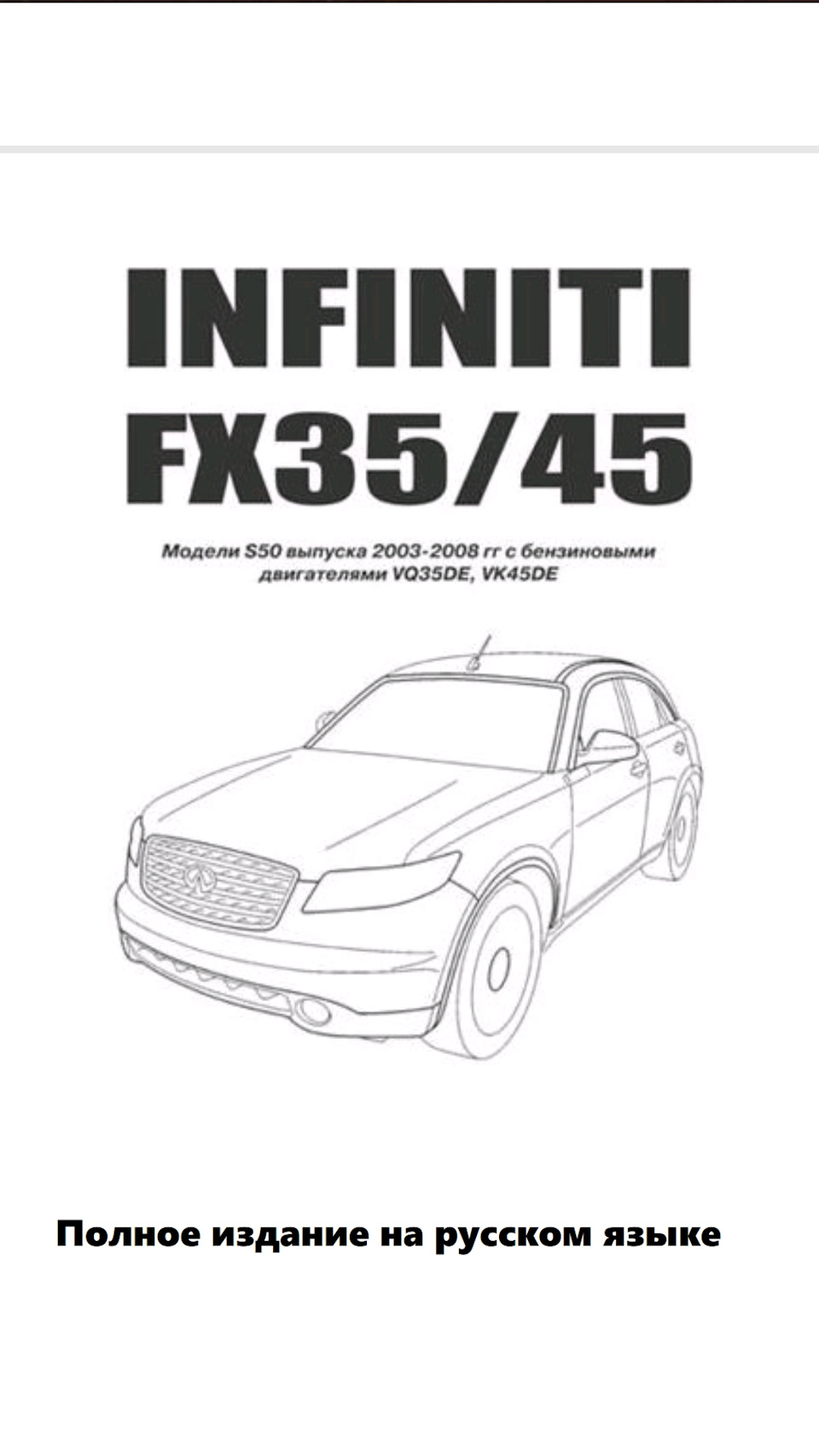
Мануал.
Устройство. Обслуживание. Ремонт.

Полный размер
Полный размер
СКАЧАТЬ с Яндекс Диск
Старался, долго сидел собирал в один файл. Работает содержимое по названиям можно сразу перейти в нужное место, вот только ссылки не осилил сделать на разные страницы, уж сильно много времени бы ушло на это, имею ввиду как в оригинале на англ. языке.
Но только нужно открыть файл в хорошем просмоторщике pdf, например adobe pdf reader, там можете открыть содержимое по названиям.
Полный размер
Factory Workshop Manual
Make
Infiniti
Model
G35 Sedan 2wd
Engine and year
V6-3.5L (VQ35DE) (2005)
Please navigate through the PDF using the options
provided by OnlyManuals.com on the sidebar.
This manual was submitted by
Anonymous
Date
1st January 2018
Infiniti G35 Sedan 2wd Workshop Manual (V6-3.5L (VQ35DE) (2005))
Infiniti Workshop Manuals > Relays and Modules > Relays and Modules — Accessories and Optional Equipment >
Navigation Module > Component Information > Locations
Navigation Module: Locations
Passenger Compartment Electrical Units Location
Infiniti G35 Sedan 2wd Workshop Manual (V6-3.5L (VQ35DE) (2005))
Infiniti Workshop Manuals > Relays and Modules > Relays and Modules — Accessories and Optional Equipment >
Navigation Module > Component Information > Locations > Page 7
Passenger Compartment Electrical Units Location Part 2
Infiniti G35 Sedan 2wd Workshop Manual (V6-3.5L (VQ35DE) (2005))
Infiniti Workshop Manuals > Relays and Modules > Relays and Modules — Accessories and Optional Equipment >
Navigation Module > Component Information > Locations > Page 8
Navigation Module: Service and Repair
Removal and Installation of NAVI Control Unit
REMOVAL
1. Remove center box assy. Refer to «INSTRUMENT PANEL ASSEMBLY»
2. Remove screws (4), and remove NAVI control unit.
3. Remove screws (4), and remove bracket.
INSTALLATION
Installation is the reverse order of removal.
Infiniti G35 Sedan 2wd Workshop Manual (V6-3.5L (VQ35DE) (2005))
Infiniti Workshop Manuals > Relays and Modules > Relays and Modules — Body and Frame > Memory Positioning Module >
Component Information > Locations
Component Parts And Harness Connector Location
Infiniti G35 Sedan 2wd Workshop Manual (V6-3.5L (VQ35DE) (2005))
Infiniti Workshop Manuals > Relays and Modules > Relays and Modules — Body and Frame > Power Seat Control Module >
Component Information > Locations
Power Seat Control Module: Locations
Component Parts And Harness Connector Location
Infiniti G35 Sedan 2wd Workshop Manual (V6-3.5L (VQ35DE) (2005))
Infiniti Workshop Manuals > Relays and Modules > Relays and Modules — Body and Frame > Power Seat Control Module >
Component Information > Locations > Page 16
Passenger Compartment Electrical Units Location
Infiniti G35 Sedan 2wd Workshop Manual (V6-3.5L (VQ35DE) (2005))
Infiniti Workshop Manuals > Relays and Modules > Relays and Modules — Body and Frame > Power Seat Control Module >
Component Information > Locations > Page 17
Component Parts And Harness Connector Location
Infiniti G35 Sedan 2wd Workshop Manual (V6-3.5L (VQ35DE) (2005))
Infiniti Workshop Manuals > Relays and Modules > Relays and Modules — Body and Frame > Seat Heater Relay >
Component Information > Locations
Passenger Compartment Electrical Units Location
Infiniti G35 Sedan 2wd Workshop Manual (V6-3.5L (VQ35DE) (2005))
Infiniti Workshop Manuals > Relays and Modules > Relays and Modules — Brakes and Traction Control > Electronic Brake
Control Module > Component Information > Technical Service Bulletins > ABS/TCS — CAN Diagnostic Information
Electronic Brake Control Module: Technical Service Bulletins ABS/TCS — CAN Diagnostic
Information
Classification: BR10-012
Reference: ITB10-074
Date: December 15, 2010
ABS / VDC CAN DIAGNOSIS INFORMATION
APPLIED VEHICLES: All 2005 — 2011 Infiniti vehicles with ABS and/or VDC
SERVICE INFORMATION
When diagnosing a vehicle with an ABS or VDC / SLIP warning light on with DTCs stored in the
ABS / VDC actuator control unit perform DTC diagnosis first.
^ Do not replace the ABS / VDC actuator control unit without being supported by the DTC
diagnosis.
^ Do not erase DTCS before performing DTC diagnosis.
^ Always fully diagnose before performing any repairs.
When DTC U1000 (CAN COMM CIRCUIT) is the only DTC stored in the ABS / VDC actuator
control unit use the REPAIR FLOW CHART shown below. This will assist in proper diagnosis
results and repairs in addition to using diagnostic information in the Electronic Service Manual
(ESM).
^ If DTC U1000 is found stored in other systems refer to NTB10-066 and the applicable ESM.
^ If other DTCs are found stored in ABS / VDC along with U1000 follow the diagnosis steps for
those DTCs in the applicable ESM.
CLAIMS INFORMATION
Refer to the current Infiniti Warranty Flat Rate Manual and use the appropriate claims coding for
repairs performed.
Infiniti G35 Sedan 2wd Workshop Manual (V6-3.5L (VQ35DE) (2005))
Infiniti Workshop Manuals > Relays and Modules > Relays and Modules — Brakes and Traction Control > Electronic Brake
Control Module > Component Information > Technical Service Bulletins > ABS/TCS — CAN Diagnostic Information > Page
26
Infiniti G35 Sedan 2wd Workshop Manual (V6-3.5L (VQ35DE) (2005))
Infiniti Workshop Manuals > Relays and Modules > Relays and Modules — Brakes and Traction Control > Electronic Brake
Control Module > Component Information > Technical Service Bulletins > ABS/TCS — CAN Diagnostic Information > Page
27
Repair Flow Chart
Infiniti G35 Sedan 2wd Workshop Manual (V6-3.5L (VQ35DE) (2005))
Infiniti Workshop Manuals > Relays and Modules > Relays and Modules — Brakes and Traction Control > Electronic Brake
Control Module > Component Information > Technical Service Bulletins > Page 28
Electronic Brake Control Module: Locations
Passenger Compartment Electrical Units Location
Infiniti G35 Sedan 2wd Workshop Manual (V6-3.5L (VQ35DE) (2005))
Infiniti Workshop Manuals > Relays and Modules > Relays and Modules — Brakes and Traction Control > Electronic Brake
Control Module > Component Information > Technical Service Bulletins > Page 29
Passenger Compartment Electrical Units Location Part 2
Infiniti G35 Sedan 2wd Workshop Manual (V6-3.5L (VQ35DE) (2005))
Infiniti Workshop Manuals > Relays and Modules > Relays and Modules — Brakes and Traction Control > Electronic Brake
Control Module > Component Information > Technical Service Bulletins > Page 30
Electrical Units — Terminal Arrangement
Infiniti G35 Sedan 2wd Workshop Manual (V6-3.5L (VQ35DE) (2005))
Infiniti Workshop Manuals > Relays and Modules > Relays and Modules — Brakes and Traction Control > Electronic Brake
Control Module > Component Information > Technical Service Bulletins > Page 31
Electronic Brake Control Module: Service and Repair
VDC/TCS/ABS CONTROL UNIT
Removal and Installation
REMOVAL
1. Remove instrument side panel (RH). Refer to «(U) Instrument Side Panel (RH/LH) 2. Remove
instrument lower cover. Refer to «(S) Instrument Lower Cover». 3. Remove VDC/TCS/ABS control
unit.
INSTALLATION Installation is the reverse order of removal.
Infiniti G35 Sedan 2wd Workshop Manual (V6-3.5L (VQ35DE) (2005))
Infiniti Workshop Manuals > Relays and Modules > Relays and Modules — Brakes and Traction Control > Traction Control
Module > Component Information > Technical Service Bulletins > ABS/TCS — CAN Diagnostic Information
Traction Control Module: Technical Service Bulletins ABS/TCS — CAN Diagnostic Information
Classification: BR10-012
Reference: ITB10-074
Date: December 15, 2010
ABS / VDC CAN DIAGNOSIS INFORMATION
APPLIED VEHICLES: All 2005 — 2011 Infiniti vehicles with ABS and/or VDC
SERVICE INFORMATION
When diagnosing a vehicle with an ABS or VDC / SLIP warning light on with DTCs stored in the
ABS / VDC actuator control unit perform DTC diagnosis first.
^ Do not replace the ABS / VDC actuator control unit without being supported by the DTC
diagnosis.
^ Do not erase DTCS before performing DTC diagnosis.
^ Always fully diagnose before performing any repairs.
When DTC U1000 (CAN COMM CIRCUIT) is the only DTC stored in the ABS / VDC actuator
control unit use the REPAIR FLOW CHART shown below. This will assist in proper diagnosis
results and repairs in addition to using diagnostic information in the Electronic Service Manual
(ESM).
^ If DTC U1000 is found stored in other systems refer to NTB10-066 and the applicable ESM.
^ If other DTCs are found stored in ABS / VDC along with U1000 follow the diagnosis steps for
those DTCs in the applicable ESM.
CLAIMS INFORMATION
Refer to the current Infiniti Warranty Flat Rate Manual and use the appropriate claims coding for
repairs performed.
Infiniti G35 Sedan 2wd Workshop Manual (V6-3.5L (VQ35DE) (2005))
Infiniti Workshop Manuals > Relays and Modules > Relays and Modules — Brakes and Traction Control > Traction Control
Module > Component Information > Technical Service Bulletins > ABS/TCS — CAN Diagnostic Information > Page 36
Infiniti G35 Sedan 2wd Workshop Manual (V6-3.5L (VQ35DE) (2005))
Infiniti Workshop Manuals > Relays and Modules > Relays and Modules — Brakes and Traction Control > Traction Control
Module > Component Information > Technical Service Bulletins > ABS/TCS — CAN Diagnostic Information > Page 37
Repair Flow Chart
Infiniti G35 Sedan 2wd Workshop Manual (V6-3.5L (VQ35DE) (2005))
Infiniti Workshop Manuals > Relays and Modules > Relays and Modules — Brakes and Traction Control > Traction Control
Module > Component Information > Technical Service Bulletins > Page 38
Traction Control Module: Locations
Passenger Compartment Electrical Units Location
Infiniti G35 Sedan 2wd Workshop Manual (V6-3.5L (VQ35DE) (2005))
Infiniti Workshop Manuals > Relays and Modules > Relays and Modules — Brakes and Traction Control > Traction Control
Module > Component Information > Technical Service Bulletins > Page 39
Passenger Compartment Electrical Units Location Part 2
Infiniti G35 Sedan 2wd Workshop Manual (V6-3.5L (VQ35DE) (2005))
Infiniti Workshop Manuals > Relays and Modules > Relays and Modules — Brakes and Traction Control > Traction Control
Module > Component Information > Technical Service Bulletins > Page 40
Electrical Units — Terminal Arrangement
Infiniti G35 Sedan 2wd Workshop Manual (V6-3.5L (VQ35DE) (2005))
Infiniti Workshop Manuals > Relays and Modules > Relays and Modules — Brakes and Traction Control > Traction Control
Module > Component Information > Technical Service Bulletins > Page 41
Traction Control Module: Description and Operation
TCS CONTROL UNIT
Description
The malfunction information related to TCS is transferred through the CAN communication line
from VDC/TCS/ABS control unit to ECM.
Be sure to erase the malfunction information such as DTC not only for VDC/TCS/ABS control unit
but also for ECM after TCS related repair.
Infiniti G35 Sedan 2wd Workshop Manual (V6-3.5L (VQ35DE) (2005))
Infiniti Workshop Manuals > Relays and Modules > Relays and Modules — Cooling System > Radiator Cooling Fan Control
Module > Component Information > Description and Operation
Radiator Cooling Fan Control Module: Description and Operation
ENGINE OVER TEMPERATURE
Description
SYSTEM DESCRIPTION
Cooling Fan Control
The ECM controls the cooling fan corresponding to the vehicle speed, engine coolant temperature,
refrigerant pressure, and air conditioner ON signal. The control system has 3-step control
[HIGH/LOW/OFF].
Cooling Fan Operation
Cooling Fan Relay Operation
COMPONENT DESCRIPTION
Infiniti G35 Sedan 2wd Workshop Manual (V6-3.5L (VQ35DE) (2005))
Infiniti Workshop Manuals > Relays and Modules > Relays and Modules — Cooling System > Radiator Cooling Fan Control
Module > Component Information > Description and Operation > Page 46
Cooling Fan Motor
The cooling fan operates at each speed when the current flows in the cooling fan motor as shown.
Infiniti G35 Sedan 2wd Workshop Manual (V6-3.5L (VQ35DE) (2005))
Infiniti Workshop Manuals > Relays and Modules > Relays and Modules — Cooling System > Radiator Cooling Fan Control
Module Relay > Component Information > Description and Operation
Infiniti G35 Sedan 2wd Workshop Manual (V6-3.5L (VQ35DE) (2005))
Infiniti Workshop Manuals > Relays and Modules > Relays and Modules — Cooling System > Radiator Cooling Fan Motor
Relay > Component Information > Locations
IPDM E/R Terminal Arrangement
Infiniti G35 Sedan 2wd Workshop Manual (V6-3.5L (VQ35DE) (2005))
Infiniti Workshop Manuals > Relays and Modules > Relays and Modules — HVAC > Blower Motor Relay > Component
Information > Locations
Blower Motor Relay: Locations
Passenger Compartment Electrical Units Location
Infiniti G35 Sedan 2wd Workshop Manual (V6-3.5L (VQ35DE) (2005))
Infiniti Workshop Manuals > Relays and Modules > Relays and Modules — HVAC > Blower Motor Relay > Component
Information > Locations > Page 57
Fuse Block-Junction Box (J/B) — Terminal Arrangement
Infiniti G35 Sedan 2wd Workshop Manual (V6-3.5L (VQ35DE) (2005))
Infiniti Workshop Manuals > Relays and Modules > Relays and Modules — HVAC > Blower Motor Relay > Component
Information > Diagrams > Diagram Information and Instructions
Blower Motor Relay: Diagram Information and Instructions
How to Read Wiring Diagrams
How to Read Wiring Diagrams
CONNECTOR SYMBOLS
Most of connector symbols in wiring diagrams are shown from the terminal side.
— Connector symbols shown from the terminal side are enclosed by a single line and followed by
the direction mark.
— Connector symbols shown from the harness side are enclosed by a double line and followed by
the direction mark.
— Certain systems and components, especially those related to OBD, may use a new style
slide-locking type harness connector. For description and how to disconnect, refer to Power Supply,
Ground & Circuit Elements, «Description», «HARNESS CONNECTOR».
— Male and female terminals Connector guides for male terminals are shown in black and female
terminals in white in wiring diagrams.
Infiniti G35 Sedan 2wd Workshop Manual (V6-3.5L (VQ35DE) (2005))
Infiniti Workshop Manuals > Relays and Modules > Relays and Modules — HVAC > Blower Motor Relay > Component
Information > Diagrams > Diagram Information and Instructions > Page 60
GI-EXAMPL-02
SAMPLE/WIRING DIAGRAM — EXAMPL —
Infiniti G35 Sedan 2wd Workshop Manual (V6-3.5L (VQ35DE) (2005))
Infiniti Workshop Manuals > Relays and Modules > Relays and Modules — HVAC > Blower Motor Relay > Component
Information > Diagrams > Diagram Information and Instructions > Page 61
Optional Splice
Part 1
Infiniti G35 Sedan 2wd Workshop Manual (V6-3.5L (VQ35DE) (2005))
Infiniti Workshop Manuals > Relays and Modules > Relays and Modules — HVAC > Blower Motor Relay > Component
Information > Diagrams > Diagram Information and Instructions > Page 62
Part 2
DESCRIPTION
Harness Indication
Infiniti G35 Sedan 2wd Workshop Manual (V6-3.5L (VQ35DE) (2005))
Infiniti Workshop Manuals > Relays and Modules > Relays and Modules — HVAC > Blower Motor Relay > Component
Information > Diagrams > Diagram Information and Instructions > Page 63
— Letter designations next to test meter probe indicate harness (connector) wire color.
— Connector numbers in a single circle M33 indicate harness connectors.
Component Indication
Connector numbers in a double circle F211 indicate component connectors.
Switch Positions
Switches are shown in wiring diagrams as if the vehicle is in the «normal» condition.
A vehicle is in the «normal» condition when:
— ignition switch is «OFF»,
— doors, hood and trunk lid/back door are closed,
— pedals are not depressed, and
— parking brake is released.
Detectable Lines and Non-Detectable Lines
Infiniti G35 Sedan 2wd Workshop Manual (V6-3.5L (VQ35DE) (2005))
Infiniti Workshop Manuals > Relays and Modules > Relays and Modules — HVAC > Blower Motor Relay > Component
Information > Diagrams > Diagram Information and Instructions > Page 64
In some wiring diagrams, two kinds of lines, representing wires, with different weight are used.
— A line with regular weight (wider line) represents a «detectable line for DTC (Diagnostic Trouble
Code)». A «detectable line for DTC» is a circuit in which ECM can detect its malfunctions with the on
board diagnostic system.
— A line with less weight (thinner line) represents a «non-detectable line for DTC». A «non-detectable
line for DTC» is a circuit in which ECM cannot detect its malfunctions with the on board diagnostic
system.
Multiple Switch
The continuity of multiple switch is described in two ways as shown here.
— The switch chart is used in schematic diagrams.
Infiniti G35 Sedan 2wd Workshop Manual (V6-3.5L (VQ35DE) (2005))
Infiniti Workshop Manuals > Relays and Modules > Relays and Modules — HVAC > Blower Motor Relay > Component
Information > Diagrams > Diagram Information and Instructions > Page 65
— The switch diagram is used in wiring diagrams.
Reference Area
The Reference Area of the wiring diagram contains references to additional electrical reference
pages at the end of the manual. If connector numbers and titles are shown in the Reference Area
of the wiring diagram, these connector symbols are not shown in the Connector Area.
Infiniti G35 Sedan 2wd Workshop Manual (V6-3.5L (VQ35DE) (2005))
Infiniti Workshop Manuals > Relays and Modules > Relays and Modules — HVAC > Blower Motor Relay > Component
Information > Diagrams > Diagram Information and Instructions > Page 66
Abbreviations
How To Read Harness Layout
HARNESS
Harness Layout
HOW TO READ HARNESS LAYOUT
The following Harness Layouts use a map style grid to help locate connectors on the figures:
— Main Harness
— Engine Room Harness (Engine Compartment)
— Engine Control Harness
— Body Harness (Passenger Compartment)
To Use the Grid Reference
1. Find the desired connector number on the connector list. 2. Find the grid reference. 3. On the
figure, find the crossing of the grid reference letter column and number row. 4. Find the connector
number in the crossing zone. 5. Follow the line (if used) to the connector.
Infiniti G35 Sedan 2wd Workshop Manual (V6-3.5L (VQ35DE) (2005))
Infiniti Workshop Manuals > Relays and Modules > Relays and Modules — HVAC > Blower Motor Relay > Component
Information > Diagrams > Diagram Information and Instructions > Page 67
CONNECTOR SYMBOL
Main symbols of connector (in Harness Layout) are indicated in the figure.
Harness Connector Description
HARNESS CONNECTOR
Description
HARNESS CONNECTOR (TAB-LOCKING TYPE)
— The tab-locking type connectors help prevent accidental looseness or disconnection.
— The tab-locking type connectors are disconnected by pushing or lifting the locking tab(s). Refer to
the figure.
CAUTION:
— Do not pull the harness or wires when disconnecting the connector.
HARNESS CONNECTOR (SLIDE-LOCKING TYPE)
Infiniti G35 Sedan 2wd Workshop Manual (V6-3.5L (VQ35DE) (2005))
Infiniti Workshop Manuals > Relays and Modules > Relays and Modules — HVAC > Blower Motor Relay > Component
Information > Diagrams > Diagram Information and Instructions > Page 68
— A new style slide-locking type connector is used on certain systems and components, especially
those related to OBD.
— The slide-locking type connectors help prevent incomplete locking and accidental looseness or
disconnection.
— The slide-locking type connectors are disconnected by pushing or pulling the slider. Refer to the
figure.
CAUTION:
— Do not pull the harness or wires when disconnecting the connector.
— Be careful not to damage the connector support bracket when disconnecting the connector.
Infiniti G35 Sedan 2wd Workshop Manual (V6-3.5L (VQ35DE) (2005))
Infiniti Workshop Manuals > Relays and Modules > Relays and Modules — HVAC > Blower Motor Relay > Component
Information > Diagrams > Diagram Information and Instructions > Page 69
Infiniti G35 Sedan 2wd Workshop Manual (V6-3.5L (VQ35DE) (2005))
Infiniti Workshop Manuals > Relays and Modules > Relays and Modules — HVAC > Blower Motor Relay > Component
Information > Diagrams > Diagram Information and Instructions > Page 70
Wire Color Code Identification
Wiring Color Code
B = Black W = White R = Red G = Green L = Blue Y = Yellow LG = Light Green
Infiniti G35 Sedan 2wd Workshop Manual (V6-3.5L (VQ35DE) (2005))
Infiniti Workshop Manuals > Relays and Modules > Relays and Modules — HVAC > Blower Motor Relay > Component
Information > Diagrams > Diagram Information and Instructions > Page 71
BR = Brown OR or O = Orange P = Pink PU or V (violet) = Purple GY or GR = Grey SB = Sky Blue
CH = Dark Brown DG = Dark Green
Wiring Diagram Codes/Abbreviations Part 1
Infiniti G35 Sedan 2wd Workshop Manual (V6-3.5L (VQ35DE) (2005))
Infiniti Workshop Manuals > Relays and Modules > Relays and Modules — HVAC > Blower Motor Relay > Component
Information > Diagrams > Diagram Information and Instructions > Page 72
Wiring Diagram Codes/Abbreviations Part 2
Infiniti G35 Sedan 2wd Workshop Manual (V6-3.5L (VQ35DE) (2005))
Infiniti Workshop Manuals > Relays and Modules > Relays and Modules — HVAC > Blower Motor Relay > Component
Information > Diagrams > Diagram Information and Instructions > Page 73
Wiring Diagram Codes/Abbreviations Part 3
Infiniti G35 Sedan 2wd Workshop Manual (V6-3.5L (VQ35DE) (2005))
Infiniti Workshop Manuals > Relays and Modules > Relays and Modules — HVAC > Blower Motor Relay > Component
Information > Diagrams > Diagram Information and Instructions > Page 74
Blower Motor Relay: Diagnostic Aids
How to Check Terminals
SERVICE INFORMATION FOR ELECTRICAL INCIDENT
How to Check Terminal
Infiniti G35 Sedan 2wd Workshop Manual (V6-3.5L (VQ35DE) (2005))
Infiniti Workshop Manuals > Relays and Modules > Relays and Modules — HVAC > Blower Motor Relay > Component
Information > Diagrams > Diagram Information and Instructions > Page 75
CONNECTOR AND TERMINAL PIN KIT
Use the connector and terminal pin kits listed when replacing connectors or terminals. The
connector and terminal pin kits contain some of the most commonly used NISSAN/INFINITI
connectors and terminals. For detailed connector and terminal pin replacement procedures, refer to
the latest NISSAN/INFINITI CONNECTOR AND TERMINAL PIN SERVICE MANUAL.
HOW TO PROBE CONNECTORS
Connector damage and an intermittent connection can result from improperly probing of the
connector during circuit checks. The probe of a digital multimeter (DMM) may not correctly fit the
connector cavity. To correctly probe the connector, follow the procedures using a «T» pin. For the
best contact grasp the «T» pin using an alligator clip.
Probing from Harness Side
Standard type (not waterproof type) connector should be probed from harness side with «T» pin.
— If the connector has a rear cover such as a ECM connector, remove the rear cover before probing
the terminal.
— Do not probe waterproof connector from harness side. Damage to the seal between wire and
connector may result.
Probing from Terminal Side
FEMALE TERMINAL
— There is a small notch above each female terminal. Probe each terminal with the «T» pin through
the notch.
Infiniti G35 Sedan 2wd Workshop Manual (V6-3.5L (VQ35DE) (2005))
Infiniti Workshop Manuals > Relays and Modules > Relays and Modules — HVAC > Blower Motor Relay > Component
Information > Diagrams > Diagram Information and Instructions > Page 76
Do not insert any object other than the same type male terminal into female terminal.
— Some connectors do not have a notch above each terminal. To probe each terminal, remove the
connector retainer to make contact space for probing.
MALE TERMINAL
Carefully probe the contact surface of each terminal using a «T» pin. Do not bend terminal.
How to Check Enlarged Contact Spring of Terminal
An enlarged contact spring of a terminal may create intermittent signals in the circuit. If the
intermittent open circuit occurs, follow the procedure to inspect for open wires and enlarged contact
spring of female terminal.
1. Assemble a male terminal and approx. 10 cm (3.9 in) of wire.
Use a male terminal which matches the female terminal.
2. Disconnect the suspected faulty connector and hold it terminal side up.
Infiniti G35 Sedan 2wd Workshop Manual (V6-3.5L (VQ35DE) (2005))
Infiniti Workshop Manuals > Relays and Modules > Relays and Modules — HVAC > Blower Motor Relay > Component
Information > Diagrams > Diagram Information and Instructions > Page 77
3. While holding the wire of the male terminal, try to insert the male terminal into the female
terminal.
Do not force the male terminal into the female terminal with your hands.
4. While moving the connector, check whether the male terminal can be easily inserted or not.
— If the male terminal can be easily inserted into the female terminal, replace the female terminal.
Waterproof Connector Inspection
If water enters the connector, it can short interior circuits. This may lead to intermittent problems.
Check the following items to maintain the original waterproof characteristics.
RUBBER SEAL INSPECTION
— Most waterproof connectors are provided with a rubber seal between the male and female
connectors. If the seal is missing, the waterproof performance may not meet specifications.
— The rubber seal may come off when connectors are disconnected. Whenever connectors are
reconnected, make sure the rubber seal is properly installed on either side of male or female
connector.
Infiniti G35 Sedan 2wd Workshop Manual (V6-3.5L (VQ35DE) (2005))
Infiniti Workshop Manuals > Relays and Modules > Relays and Modules — HVAC > Blower Motor Relay > Component
Information > Diagrams > Diagram Information and Instructions > Page 78
WIRE SEAL INSPECTION
The wire seal must be installed on the wire insertion area of a waterproof connector. Be sure that
the seal is installed properly.
Terminal Lock Inspection
Check for unlocked terminals by pulling wire at the end of connector. An unlocked terminal may
create intermittent signals in the circuit.
How to Perform Electrical Incident Simulation Tests
How to Perform Efficient Diagnosis for an Electrical Incident
Infiniti G35 Sedan 2wd Workshop Manual (V6-3.5L (VQ35DE) (2005))
Infiniti Workshop Manuals > Relays and Modules > Relays and Modules — HVAC > Blower Motor Relay > Component
Information > Diagrams > Diagram Information and Instructions > Page 79
Work Flow
WORK FLOW
INCIDENT SIMULATION TESTS
Introduction
Sometimes the symptom is not present when the vehicle is brought in for service. If possible,
re-create the conditions present at the time of the incident. Doing so may help avoid a No Trouble
Found Diagnosis. The following section illustrates ways to simulate the conditions/environment
under which the owner experiences an electrical incident.
The section is broken into the six following topics:
— Vehicle vibration
— Heat sensitive
— Freezing
— Water intrusion
— Electrical load
Infiniti G35 Sedan 2wd Workshop Manual (V6-3.5L (VQ35DE) (2005))
Infiniti Workshop Manuals > Relays and Modules > Relays and Modules — HVAC > Blower Motor Relay > Component
Information > Diagrams > Diagram Information and Instructions > Page 80
— Cold or hot start up
Get a thorough description of the incident from the customer. It is important for simulating the
conditions of the problem.
Vehicle Vibration
The problem may occur or become worse while driving on a rough road or when engine is vibrating
(idle with A/C on). In such a case, you will want to check for a vibration related condition. Refer to
the following illustration.
CONNECTORS & HARNESS
Determine which connectors and wiring harness would affect the electrical system you are
inspecting. Gently shake each connector and harness while monitoring the system for the incident
you are trying to duplicate. This test may indicate a loose or poor electrical connection.
HINT
Connectors can be exposed to moisture. It is possible to get a thin film of corrosion on the
connector terminals. A visual inspection may not reveal this without disconnecting the connector. If
the problem occurs intermittently, perhaps the problem is caused by corrosion. It is a good idea to
disconnect, inspect and clean the terminals on related connectors in the system.
SENSORS & RELAYS
Gently apply a slight vibration to sensors and relays in the system you are inspecting. This test may
indicate a loose or poorly mounted sensor or relay.
ENGINE COMPARTMENT
There are several reasons a vehicle or engine vibration could cause an electrical complaint. Some
of the things to check for are:
— Connectors not fully seated.
— Wiring harness not long enough and is being stressed due to engine vibrations or rocking.
— Wires laying across brackets or moving components.
— Loose, dirty or corroded ground wires.
— Wires routed too close to hot components.
To inspect components under the hood, start by verifying the integrity of ground connections.
(Refer to Ground Inspection described later.) First check that the system is properly grounded.
Then check for loose connection by gently shaking the wiring or components as previously
explained. Using the wiring diagrams inspect the wiring for continuity.
BEHIND THE INSTRUMENT PANEL
An improperly routed or improperly clamped harness can become pinched during accessory
installation. Vehicle vibration can aggravate a harness which is routed along a bracket or near a
screw.
UNDER SEATING AREAS
An unclamped or loose harness can cause wiring to be pinched by seat components (such as slide
guides) during vehicle vibration. If the wiring runs under seating areas, inspect wire routing for
possible damage or pinching.
Infiniti G35 Sedan 2wd Workshop Manual (V6-3.5L (VQ35DE) (2005))
Infiniti Workshop Manuals > Relays and Modules > Relays and Modules — HVAC > Blower Motor Relay > Component
Information > Diagrams > Diagram Information and Instructions > Page 81
Heat Sensitive
The customer’s concern may occur during hot weather or after car has sat for a short time. In such
cases you will want to check for a heat sensitive condition.
To determine if an electrical component is heat sensitive, heat the component with a heat gun or
equivalent. Do not heat components above 60 °C (140 °F). If incident occurs while heating the unit,
either replace or properly insulate the component.
Freezing
The customer may indicate the incident goes away after the car warms up (winter time). The cause
could be related to water freezing somewhere in the wiring/electrical system.
There are two methods to check for this. The first is to arrange for the owner to leave his car
overnight. Make sure it will get cold enough to demonstrate his complaint. Leave the car parked
outside overnight. In the morning, do a quick and thorough diagnosis of those electrical
components which could be affected.
The second method is to put the suspect component into a freezer long enough for any water to
freeze. Reinstall the part into the car and check for the reoccurrence of the incident. If it occurs,
repair or replace the component.
Water Intrusion
The incident may occur only during high humidity or in rainy/snowy weather. In such cases the
incident could be caused by water intrusion on an electrical part. This can be simulated by soaking
the car or running it through a car wash. Do not spray water directly on any electrical components.
Infiniti G35 Sedan 2wd Workshop Manual (V6-3.5L (VQ35DE) (2005))
Infiniti Workshop Manuals > Relays and Modules > Relays and Modules — HVAC > Blower Motor Relay > Component
Information > Diagrams > Diagram Information and Instructions > Page 82
Electrical Load
The incident may be electrical load sensitive. Perform diagnosis with all accessories (including A/C,
rear window defogger, radio, fog lamps) turned on.
Cold or Hot Start Up
On some occasions an electrical incident may occur only when the car is started cold, or it may
occur when the car is restarted hot shortly after being turned off. In these cases you may have to
keep the car overnight to make a proper diagnosis.
CIRCUIT INSPECTION
Introduction
In general, testing electrical circuits is an easy task if it is approached in a logical and organized
method.
Before beginning it is important to have all available information on the system to be tested. Also,
get a thorough understanding of system operation. Then you will be able to use the appropriate
equipment and follow the correct test procedure. You may have to simulate vehicle vibrations while
testing electrical components. Gently shake the wiring harness or electrical component to do this.
NOTE: Refer to «How to Check Terminal» to probe or check terminal.
Testing for «Opens» in the Circuit
Before you begin to diagnose and test the system, you should rough sketch a schematic of the
system. This will help you to logically walk through the diagnosis process. Drawing the sketch will
also reinforce your working knowledge of the system.
CONTINUITY CHECK METHOD
The continuity check is used to find an open in the circuit. The digital multimeter (DMM) set on the
resistance function will indicate an open circuit as over limit (no beep tone or no ohms symbol).
Make sure to always start with the DMM at the highest resistance level.
To help in understanding the diagnosis of open circuits, please refer to the previous schematic.
— Disconnect the battery negative cable.
Infiniti G35 Sedan 2wd Workshop Manual (V6-3.5L (VQ35DE) (2005))
Infiniti Workshop Manuals > Relays and Modules > Relays and Modules — HVAC > Blower Motor Relay > Component
Information > Diagrams > Diagram Information and Instructions > Page 83
— Start at one end of the circuit and work your way to the other end. (At the fuse block in this
example)
— Connect one probe of the DMM to the fuse block terminal on the load side.
— Connect the other probe to the fuse block (power) side of SW1. Little or no resistance will indicate
that portion of the circuit has good continuity. If there were an open in the circuit, the DMM would
indicate an over limit or infinite resistance condition. (point A)
— Connect the probes between SW1 and the relay. Little or no resistance will indicate that portion of
the circuit has good continuity. If there were an open in the circuit, the DMM would indicate an over
limit or infinite resistance condition. (point B)
— Connect the probes between the relay and the solenoid. Little or no resistance will indicate that
portion of the circuit has good continuity. If there were an open in the circuit, the DMM would
indicate an over limit or infinite resistance condition. (point C)
Any circuit can be diagnosed using the approach in the previous example.
VOLTAGE CHECK METHOD
To help in understanding the diagnosis of open circuits please refer to the previous schematic. In
any powered circuit, an open can be found by methodically checking the system for the presence
of voltage.
This is done by switching the DMM to the voltage function.
— Connect one probe of the DMM to a known good ground.
— Begin probing at one end of the circuit and work your way to the other end.
— With SW1 open, probe at SW1 to check for voltage. voltage; open is further down the circuit than
SW1. no voltage; open is between fuse block and SW1 (point A).
— Close SW1 and probe at relay. voltage; open is further down the circuit than the relay. no voltage;
open is between SW1 and relay (point B).
— Close the relay and probe at the solenoid. voltage; open is further down the circuit than the
solenoid. no voltage; open is between relay and solenoid (point C).
Any powered circuit can be diagnosed using the approach in the previous example.
Testing for «Shorts» in the Circuit
RESISTANCE CHECK METHOD
— Disconnect the battery negative cable and remove the blown fuse.
— Disconnect all loads (SW1 open, relay disconnected and solenoid disconnected) powered through
the fuse.
— Connect one probe of the DMM to the load side of the fuse terminal. Connect the other probe to a
known good ground.
— With SW1 open, check for continuity. continuity; short is between fuse terminal and SW1 (point
A). no continuity; short is further down the circuit than SW1.
— Close SW1 and disconnect the relay. Put probes at the load side of fuse terminal and a known
good ground. Then, check for continuity. continuity; short is between SW1 and the relay (point B).
no continuity; short is further down the circuit than the relay.
— Close SW1 and jump the relay contacts with jumper wire. Put probes at the load side of fuse
terminal and a known good ground. Then, check for continuity. continuity; short is between relay
and solenoid (point C). no continuity; check solenoid, retrace steps.
Infiniti G35 Sedan 2wd Workshop Manual (V6-3.5L (VQ35DE) (2005))
Infiniti Workshop Manuals > Relays and Modules > Relays and Modules — HVAC > Blower Motor Relay > Component
Information > Diagrams > Diagram Information and Instructions > Page 84
VOLTAGE CHECK METHOD
— Remove the blown fuse and disconnect all loads (i.e. SW1 open, relay disconnected and solenoid
disconnected) powered through the fuse.
— Turn the ignition key to the ON or START position. Verify battery voltage at the battery + side of
the fuse terminal (one lead on the battery + terminal side of the fuse block and one lead on a
known good ground).
— With SW1 open and the DMM leads across both fuse terminals, check for voltage. voltage; short
is between fuse block and SW1 (point A). no voltage; short is further down the circuit than SW1.
— With SW1 closed, relay and solenoid disconnected and the DMM leads across both fuse
terminals, check for voltage. voltage; short is between SW1 and the relay (point B). no voltage;
short is further down the circuit than the relay.
— With SW1 closed, relay contacts jumped with fused jumper wire check for voltage. voltage; short
is down the circuit of the relay or between the relay and the disconnected solenoid (point C). no
voltage; retrace steps and check power to fuse block.
Ground Inspection
Ground connections are very important to the proper operation of electrical and electronic circuits.
Ground connections are often exposed to moisture, dirt and other corrosive elements. The
corrosion (rust) can become an unwanted resistance. This unwanted resistance can change the
way a circuit works.
Electronically controlled circuits are very sensitive to proper grounding. A loose or corroded ground
can drastically affect an electronically controlled circuit. A poor or corroded ground can easily affect
the circuit. Even when the ground connection looks clean, there can be a thin film of rust on the
surface.
When inspecting a ground connection follow these rules:
— Remove the ground bolt or screw.
— Inspect all mating surfaces for tarnish, dirt, rust, etc.
— Clean as required to assure good contact.
— Reinstall bolt or screw securely.
— Inspect for «add-on» accessories which may be interfering with the ground circuit.
— If several wires are crimped into one ground eyelet terminal, check for proper crimps. Make sure
all of the wires are clean, securely fastened and providing a good ground path. If multiple wires are
cased in one eyelet make sure no ground wires have excess wire insulation.
Voltage Drop Tests
Voltage drop tests are often used to find components or circuits which have excessive resistance.
A voltage drop in a circuit is caused by a resistance when the circuit is in operation.
Check the wire in the illustration. When measuring resistance with DMM, contact by a single strand
of wire will give reading of 0 ohms. This would indicate a good circuit. When the circuit operates,
this single strand of wire is not able to carry the current. The single strand will have a high
resistance to the current. This will be picked up as a slight voltage drop.
Infiniti G35 Sedan 2wd Workshop Manual (V6-3.5L (VQ35DE) (2005))
Infiniti Workshop Manuals > Relays and Modules > Relays and Modules — HVAC > Blower Motor Relay > Component
Information > Diagrams > Diagram Information and Instructions > Page 85
Unwanted resistance can be caused by many situations as follows:
— Undersized wiring (single strand example)
— Corrosion on switch contacts
— Loose wire connections or splices.
If repairs are needed always use wire that is of the same or larger gauge.
MEASURING VOLTAGE DROP — ACCUMULATED METHOD
— Connect the DMM across the connector or part of the circuit you want to check. The positive lead
of the DMM should be closer to power and the negative lead closer to ground.
— Operate the circuit.
— The DMM will indicate how many volts are being used to «push» current through that part of the
circuit.
Note in the illustration that there is an excessive 4.1 volt drop between the battery and the bulb.
MEASURING VOLTAGE DROP — STEP-BY-STEP
The step-by-step method is most useful for isolating excessive drops in low voltage systems (such
as those in «Computer Controlled Systems»).
Circuits in the «Computer Controlled System» operate on very low amperage. The (Computer
Controlled) system operations can be adversely affected by any variation in resistance in the
system. Such resistance variation may be caused by poor connection, improper installation,
improper wire gauge or corrosion.
Infiniti G35 Sedan 2wd Workshop Manual (V6-3.5L (VQ35DE) (2005))
Infiniti Workshop Manuals > Relays and Modules > Relays and Modules — HVAC > Blower Motor Relay > Component
Information > Diagrams > Diagram Information and Instructions > Page 86
The step by step voltage drop test can identify a component or wire with too much resistance.
Control Unit Circuit Test
INPUT-OUTPUT VOLTAGE CHART
INPUT-OUTPUT VOLTAGE CHART
Control Units and Electrical Parts
PRECAUTIONS
Infiniti G35 Sedan 2wd Workshop Manual (V6-3.5L (VQ35DE) (2005))
Infiniti Workshop Manuals > Relays and Modules > Relays and Modules — HVAC > Blower Motor Relay > Component
Information > Diagrams > Diagram Information and Instructions > Page 87
— Never reverse polarity of battery terminals.
— Install only parts specified for a vehicle.
— Before replacing the control unit, check the input and output and functions of the component
parts.
— Do not apply excessive force when disconnecting a connector.
— If a connector is installed by tightening bolts, loosen bolt mounting it, then take it out by hand.
— Before installing a connector, make sure the terminal is not bent or damaged, and then correctly
connect it. When installing a connector by tightening bolts, fix it by tightening the mounting bolt until
the painted projection of the connector becomes even with the surface.
— For removal of the lever type connector, pull the lever up to the direction pointed to by the arrow A
in the figure, and then remove the connector.
— For installation of the lever type connector, pull down the lever to the direction pointed by the
arrow B in the figure, and then push the connector until a clicking noise is heard.
Infiniti G35 Sedan 2wd Workshop Manual (V6-3.5L (VQ35DE) (2005))
Infiniti Workshop Manuals > Relays and Modules > Relays and Modules — HVAC > Blower Motor Relay > Component
Information > Diagrams > Diagram Information and Instructions > Page 88
— Do not apply excessive shock to the control unit by dropping or hitting it.
— Be careful to prevent condensation in the control unit due to rapid temperature changes and do
not let water or rain get on it. If water is found in the control unit, dry it fully and then install it in the
vehicle.
— Be careful not to let oil to get on the control unit connector.
— Avoid cleaning the control unit with volatile oil.
— Do not disassemble the control unit, and do not remove the upper and lower covers.
— When using a DMM, be careful not to let test probes get close to each other to prevent the power
transistor in the control unit from damaging battery voltage because of short circuiting.
— When checking input and output signals of the control unit, use the specified check adapter.
How to Follow/Perform Trouble Diagnosis
How to Follow Trouble Diagnoses
DESCRIPTION
NOTE: Trouble diagnosis indicate work procedures required to diagnose problems effectively.
Observe the following instructions before diagnosing.
1. Before performing trouble diagnosis, read the «Preliminary Check», the «Symptom Matrix Chart»
or the «Work Flow». 2. After repairs, re-check that the problem has been completely eliminated. 3.
Refer to Component Parts and Harness Connector Location for the Systems described in each
section for identification/location of components and
harness connectors.
4. Refer to the Circuit Diagram for quick pinpoint check.
If you need to check circuit continuity between harness connectors in more detail, such as when a
sub-harness is used, refer to Wiring Diagram in each individual section and Harness Layout in
Power Supply, Ground & Ciruit Elements for identification of harness connectors.
5. When checking circuit continuity, ignition switch should be OFF. 6. Before checking voltage at
connectors, check battery voltage. 7. After accomplishing the Diagnostic Procedures and Electrical
Components Inspection, make sure that all harness connectors are reconnected as
Infiniti G35 Sedan 2wd Workshop Manual (V6-3.5L (VQ35DE) (2005))
Infiniti Workshop Manuals > Relays and Modules > Relays and Modules — HVAC > Blower Motor Relay > Component
Information > Diagrams > Diagram Information and Instructions > Page 89
they were.
HOW TO FOLLOW TEST GROUPS IN TROUBLE DIAGNOSES
1. Work and diagnostic procedure
Start to diagnose a problem using procedures indicated in enclosed test groups.
2. Questions and required results
Questions and required results are indicated in bold type in test group. The meaning of are as
follows: a. Battery voltage -> 11 — 14V or approximately 12V b. Voltage: Approximately 0V -> Less
than 1V
3. Symbol used in illustration
Symbols included in illustrations refer to measurements or procedures. Before diagnosing a
problem, familiarize yourself with each symbol. Refer to «Connector Symbols» in General
Information and «KEY TO SYMBOLS SIGNIFYING MEASUREMENTS OR PROCEDURES».
4. Action items
Next action for each test group is indicated based on result of each question. Test group number is
shown in the left upper portion of each test group.
HARNESS WIRE COLOR AND CONNECTOR NUMBER INDICATION
There are two types of harness wire color and connector number indication.
TYPE 1: Harness Wire Color and Connector Number are Shown in Illustration
Infiniti G35 Sedan 2wd Workshop Manual (V6-3.5L (VQ35DE) (2005))
Infiniti Workshop Manuals > Relays and Modules > Relays and Modules — HVAC > Blower Motor Relay > Component
Information > Diagrams > Diagram Information and Instructions > Page 90
— Letter designations next to test meter probe indicate harness wire color.
— Connector numbers in a single circle (e.g. M33) indicate harness connectors.
— Connector numbers in a double circle (e.g. F211) indicate component connectors.
TYPE 2: Harness Wire Color and Connector Number are Shown in Text
Infiniti G35 Sedan 2wd Workshop Manual (V6-3.5L (VQ35DE) (2005))
Infiniti Workshop Manuals > Relays and Modules > Relays and Modules — HVAC > Blower Motor Relay > Component
Information > Diagrams > Diagram Information and Instructions > Page 91
Infiniti G35 Sedan 2wd Workshop Manual (V6-3.5L (VQ35DE) (2005))
Infiniti Workshop Manuals > Relays and Modules > Relays and Modules — HVAC > Blower Motor Relay > Component
Information > Diagrams > Diagram Information and Instructions > Page 92
KEY TO SYMBOLS SIGNIFYING MEASUREMENTS OR PROCEDURES
CONSULT-II Checking System
CONSULT-II CHECKING SYSTEM
Description
— CONSULT-II is a hand-held type tester. When it is connected with a diagnostic connector
equipped on the vehicle side, it will communicate with the control unit equipped in the vehicle and
then enable various kinds of diagnostic tests.
— Refer to «CONSULT-II Software Operation Manual» for more information.
Infiniti G35 Sedan 2wd Workshop Manual (V6-3.5L (VQ35DE) (2005))
Infiniti Workshop Manuals > Relays and Modules > Relays and Modules — HVAC > Blower Motor Relay > Component
Information > Diagrams > Diagram Information and Instructions > Page 93
Function and System Application
Nickel Metal Hydride Battery Replacement
CONSULT-II contains a nickel metal hydride battery. When replacing the battery obey the
following:
WARNING: Replace the nickel metal hydride battery with Genuine CONSULT-II battery only. Use
of another battery may present a risk of fire or explosion. The battery may present a fire or
chemical burn hazard if mistreated. Do not recharge, disassemble or dispose of in fire. Keep the
battery out of reach of children and discard used battery conforming to the local regulations.
Infiniti G35 Sedan 2wd Workshop Manual (V6-3.5L (VQ35DE) (2005))
Infiniti Workshop Manuals > Relays and Modules > Relays and Modules — HVAC > Blower Motor Relay > Component
Information > Diagrams > Diagram Information and Instructions > Page 94
Checking Equipment
NOTE:
— The CONSULT-II must be used in conjunction with a program card. CONSULT-II does not require
loading (Initialization) procedure.
— Be sure the CONSULT-II is turned off before installing or removing a program card.
CAUTION:
— Previous CONSULT-II «I» and «Y» DLC-I and DLC-II cables should NOT be used anymore
because their DDL connector pins can be damaged during cable swapping.
— If CONSULT-II is used with no connection of CONSULT-II CONVERTER, malfunctions might be
detected in self-diagnosis depending on control unit which carry out CAN communication.
— If CONVERTER is not connected with CONSULT-II, vehicle occur the «FAIL SAFE MODE» which
is «LIGHT UP the HEAD LIGHT» and/or «COOLING FAN ROTATING» when CONSULT-II is
started.
CONSULT-II Start Procedure
NOTE: Turning ignition switch off when performing CAN diagnosis could cause CAN memory to be
erased.
1. Connect CONSULT-II and CONSULT-II CONVERTER to the data link connector.
2. If necessary, turn on the ignition switch. 3. Touch «START(NISSAN BASED VHCL)» or System
Shortcut key
(eg: ENGINE) on the screen.
Infiniti G35 Sedan 2wd Workshop Manual (V6-3.5L (VQ35DE) (2005))
Infiniti Workshop Manuals > Relays and Modules > Relays and Modules — HVAC > Blower Motor Relay > Component
Information > Diagrams > Diagram Information and Instructions > Page 95
CONSULT-II Data Link Connector (DLC) Circuit
CONSULT-II Data Link Connector (DLC) Circuit
Infiniti G35 Sedan 2wd Workshop Manual (V6-3.5L (VQ35DE) (2005))
Infiniti Workshop Manuals > Relays and Modules > Relays and Modules — HVAC > Blower Motor Relay > Component
Information > Diagrams > Diagram Information and Instructions > Page 96
INSPECTION PROCEDURE
If the CONSULT-II cannot diagnose the system properly, check the following items.
NOTE: The DDL1 and DDL2 circuits from DLC pins 12, 13, 14 and 15 may be connected to more
than one system. A short in a DDL circuit connected to a control unit in one system may affect
CONSULT-II access to other systems.
Ground Inspection
Ground Inspection
Ground connections are very important to the proper operation of electrical and electronic circuits.
Ground connections are often exposed to moisture, dirt and other corrosive elements. The
corrosion (rust) can become an unwanted resistance. This unwanted resistance can change the
way a circuit works.
Electronically controlled circuits are very sensitive to proper grounding. A loose or corroded ground
can drastically affect an electronically controlled circuit. A poor or corroded ground can easily affect
the circuit. Even when the ground connection looks clean, there can be a thin film of rust on the
surface.
When inspecting a ground connection follow these rules:
— Remove the ground bolt or screw.
— Inspect all mating surfaces for tarnish, dirt, rust, etc.
— Clean as required to assure good contact.
— Reinstall bolt or screw securely.
— Inspect for «add-on» accessories which may be interfering with the ground circuit.
— If several wires are crimped into one ground eyelet terminal, check for proper crimps. Make sure
all of the wires are clean, securely fastened and providing a good ground path. If multiple wires are
cased in one eyelet make sure no ground wires have excess wire insulation.
For detailed ground distribution information, refer to «Ground Distribution».
Work Flow
Infiniti G35 Sedan 2wd Workshop Manual (V6-3.5L (VQ35DE) (2005))
Infiniti Workshop Manuals > Relays and Modules > Relays and Modules — HVAC > Blower Motor Relay > Component
Information > Diagrams > Diagram Information and Instructions > Page 97
Work Flow Chart
Description
Infiniti G35 Sedan 2wd Workshop Manual (V6-3.5L (VQ35DE) (2005))
Infiniti Workshop Manuals > Relays and Modules > Relays and Modules — HVAC > Control Module HVAC > Component
Information > Diagrams > Diagram Information and Instructions
Control Module HVAC: Diagram Information and Instructions
How to Read Wiring Diagrams
How to Read Wiring Diagrams
CONNECTOR SYMBOLS
Most of connector symbols in wiring diagrams are shown from the terminal side.
— Connector symbols shown from the terminal side are enclosed by a single line and followed by
the direction mark.
— Connector symbols shown from the harness side are enclosed by a double line and followed by
the direction mark.
— Certain systems and components, especially those related to OBD, may use a new style
slide-locking type harness connector. For description and how to disconnect, refer to Power Supply,
Ground & Circuit Elements, «Description», «HARNESS CONNECTOR».
— Male and female terminals Connector guides for male terminals are shown in black and female
terminals in white in wiring diagrams.
Infiniti G35 Sedan 2wd Workshop Manual (V6-3.5L (VQ35DE) (2005))
Infiniti Workshop Manuals > Relays and Modules > Relays and Modules — HVAC > Control Module HVAC > Component
Information > Diagrams > Diagram Information and Instructions > Page 102
GI-EXAMPL-02
SAMPLE/WIRING DIAGRAM — EXAMPL —
Infiniti G35 Sedan 2wd Workshop Manual (V6-3.5L (VQ35DE) (2005))
Infiniti Workshop Manuals > Relays and Modules > Relays and Modules — HVAC > Control Module HVAC > Component
Information > Diagrams > Diagram Information and Instructions > Page 103
Optional Splice
Part 1
Infiniti G35 Sedan 2wd Workshop Manual (V6-3.5L (VQ35DE) (2005))
Infiniti Workshop Manuals > Relays and Modules > Relays and Modules — HVAC > Control Module HVAC > Component
Information > Diagrams > Diagram Information and Instructions > Page 104
Part 2
DESCRIPTION
Harness Indication
Infiniti G35 Sedan 2wd Workshop Manual (V6-3.5L (VQ35DE) (2005))
Infiniti Workshop Manuals > Relays and Modules > Relays and Modules — HVAC > Control Module HVAC > Component
Information > Diagrams > Diagram Information and Instructions > Page 105
— Letter designations next to test meter probe indicate harness (connector) wire color.
— Connector numbers in a single circle M33 indicate harness connectors.
Component Indication
Connector numbers in a double circle F211 indicate component connectors.
Switch Positions
Switches are shown in wiring diagrams as if the vehicle is in the «normal» condition.
A vehicle is in the «normal» condition when:
— ignition switch is «OFF»,
— doors, hood and trunk lid/back door are closed,
— pedals are not depressed, and
— parking brake is released.
Detectable Lines and Non-Detectable Lines
Infiniti G35 Sedan 2wd Workshop Manual (V6-3.5L (VQ35DE) (2005))
Infiniti Workshop Manuals > Relays and Modules > Relays and Modules — HVAC > Control Module HVAC > Component
Information > Diagrams > Diagram Information and Instructions > Page 106
In some wiring diagrams, two kinds of lines, representing wires, with different weight are used.
— A line with regular weight (wider line) represents a «detectable line for DTC (Diagnostic Trouble
Code)». A «detectable line for DTC» is a circuit in which ECM can detect its malfunctions with the on
board diagnostic system.
— A line with less weight (thinner line) represents a «non-detectable line for DTC». A «non-detectable
line for DTC» is a circuit in which ECM cannot detect its malfunctions with the on board diagnostic
system.
Multiple Switch
The continuity of multiple switch is described in two ways as shown here.
— The switch chart is used in schematic diagrams.
Infiniti G35 Sedan 2wd Workshop Manual (V6-3.5L (VQ35DE) (2005))
Infiniti Workshop Manuals > Relays and Modules > Relays and Modules — HVAC > Control Module HVAC > Component
Information > Diagrams > Diagram Information and Instructions > Page 107
— The switch diagram is used in wiring diagrams.
Reference Area
The Reference Area of the wiring diagram contains references to additional electrical reference
pages at the end of the manual. If connector numbers and titles are shown in the Reference Area
of the wiring diagram, these connector symbols are not shown in the Connector Area.
Infiniti G35 Sedan 2wd Workshop Manual (V6-3.5L (VQ35DE) (2005))
Infiniti Workshop Manuals > Relays and Modules > Relays and Modules — HVAC > Control Module HVAC > Component
Information > Diagrams > Diagram Information and Instructions > Page 108
Abbreviations
How To Read Harness Layout
HARNESS
Harness Layout
HOW TO READ HARNESS LAYOUT
The following Harness Layouts use a map style grid to help locate connectors on the figures:
— Main Harness
— Engine Room Harness (Engine Compartment)
— Engine Control Harness
— Body Harness (Passenger Compartment)
To Use the Grid Reference
1. Find the desired connector number on the connector list. 2. Find the grid reference. 3. On the
figure, find the crossing of the grid reference letter column and number row. 4. Find the connector
number in the crossing zone. 5. Follow the line (if used) to the connector.
Infiniti G35 Sedan 2wd Workshop Manual (V6-3.5L (VQ35DE) (2005))
Infiniti Workshop Manuals > Relays and Modules > Relays and Modules — HVAC > Control Module HVAC > Component
Information > Diagrams > Diagram Information and Instructions > Page 109
CONNECTOR SYMBOL
Main symbols of connector (in Harness Layout) are indicated in the figure.
Harness Connector Description
HARNESS CONNECTOR
Description
HARNESS CONNECTOR (TAB-LOCKING TYPE)
— The tab-locking type connectors help prevent accidental looseness or disconnection.
— The tab-locking type connectors are disconnected by pushing or lifting the locking tab(s). Refer to
the figure.
CAUTION:
— Do not pull the harness or wires when disconnecting the connector.
HARNESS CONNECTOR (SLIDE-LOCKING TYPE)
Infiniti G35 Sedan 2wd Workshop Manual (V6-3.5L (VQ35DE) (2005))
Infiniti Workshop Manuals > Relays and Modules > Relays and Modules — HVAC > Control Module HVAC > Component
Information > Diagrams > Diagram Information and Instructions > Page 110
— A new style slide-locking type connector is used on certain systems and components, especially
those related to OBD.
— The slide-locking type connectors help prevent incomplete locking and accidental looseness or
disconnection.
— The slide-locking type connectors are disconnected by pushing or pulling the slider. Refer to the
figure.
CAUTION:
— Do not pull the harness or wires when disconnecting the connector.
— Be careful not to damage the connector support bracket when disconnecting the connector.
Infiniti G35 Sedan 2wd Workshop Manual (V6-3.5L (VQ35DE) (2005))
Infiniti Workshop Manuals > Relays and Modules > Relays and Modules — HVAC > Control Module HVAC > Component
Information > Diagrams > Diagram Information and Instructions > Page 111
Infiniti G35 Sedan 2wd Workshop Manual (V6-3.5L (VQ35DE) (2005))
Infiniti Workshop Manuals > Relays and Modules > Relays and Modules — HVAC > Control Module HVAC > Component
Information > Diagrams > Diagram Information and Instructions > Page 112
Wire Color Code Identification
Wiring Color Code
B = Black W = White R = Red G = Green L = Blue Y = Yellow LG = Light Green
Infiniti G35 Sedan 2wd Workshop Manual (V6-3.5L (VQ35DE) (2005))
Infiniti Workshop Manuals > Relays and Modules > Relays and Modules — HVAC > Control Module HVAC > Component
Information > Diagrams > Diagram Information and Instructions > Page 113
BR = Brown OR or O = Orange P = Pink PU or V (violet) = Purple GY or GR = Grey SB = Sky Blue
CH = Dark Brown DG = Dark Green
Wiring Diagram Codes/Abbreviations Part 1
Infiniti G35 Sedan 2wd Workshop Manual (V6-3.5L (VQ35DE) (2005))
Infiniti Workshop Manuals > Relays and Modules > Relays and Modules — HVAC > Control Module HVAC > Component
Information > Diagrams > Diagram Information and Instructions > Page 114
Wiring Diagram Codes/Abbreviations Part 2
Infiniti G35 Sedan 2wd Workshop Manual (V6-3.5L (VQ35DE) (2005))
Infiniti Workshop Manuals > Relays and Modules > Relays and Modules — HVAC > Control Module HVAC > Component
Information > Diagrams > Diagram Information and Instructions > Page 115
Wiring Diagram Codes/Abbreviations Part 3
Infiniti G35 Sedan 2wd Workshop Manual (V6-3.5L (VQ35DE) (2005))
Infiniti Workshop Manuals > Relays and Modules > Relays and Modules — HVAC > Control Module HVAC > Component
Information > Diagrams > Diagram Information and Instructions > Page 116
Control Module HVAC: Diagnostic Aids
How to Check Terminals
SERVICE INFORMATION FOR ELECTRICAL INCIDENT
How to Check Terminal
Infiniti G35 Sedan 2wd Workshop Manual (V6-3.5L (VQ35DE) (2005))
Infiniti Workshop Manuals > Relays and Modules > Relays and Modules — HVAC > Control Module HVAC > Component
Information > Diagrams > Diagram Information and Instructions > Page 117
CONNECTOR AND TERMINAL PIN KIT
Use the connector and terminal pin kits listed when replacing connectors or terminals. The
connector and terminal pin kits contain some of the most commonly used NISSAN/INFINITI
connectors and terminals. For detailed connector and terminal pin replacement procedures, refer to
the latest NISSAN/INFINITI CONNECTOR AND TERMINAL PIN SERVICE MANUAL.
HOW TO PROBE CONNECTORS
Connector damage and an intermittent connection can result from improperly probing of the
connector during circuit checks. The probe of a digital multimeter (DMM) may not correctly fit the
connector cavity. To correctly probe the connector, follow the procedures using a «T» pin. For the
best contact grasp the «T» pin using an alligator clip.
Probing from Harness Side
Standard type (not waterproof type) connector should be probed from harness side with «T» pin.
— If the connector has a rear cover such as a ECM connector, remove the rear cover before probing
the terminal.
— Do not probe waterproof connector from harness side. Damage to the seal between wire and
connector may result.
Probing from Terminal Side
FEMALE TERMINAL
— There is a small notch above each female terminal. Probe each terminal with the «T» pin through
the notch.
Infiniti G35 Sedan 2wd Workshop Manual (V6-3.5L (VQ35DE) (2005))
Infiniti Workshop Manuals > Relays and Modules > Relays and Modules — HVAC > Control Module HVAC > Component
Information > Diagrams > Diagram Information and Instructions > Page 118
Do not insert any object other than the same type male terminal into female terminal.
— Some connectors do not have a notch above each terminal. To probe each terminal, remove the
connector retainer to make contact space for probing.
MALE TERMINAL
Carefully probe the contact surface of each terminal using a «T» pin. Do not bend terminal.
How to Check Enlarged Contact Spring of Terminal
An enlarged contact spring of a terminal may create intermittent signals in the circuit. If the
intermittent open circuit occurs, follow the procedure to inspect for open wires and enlarged contact
spring of female terminal.
1. Assemble a male terminal and approx. 10 cm (3.9 in) of wire.
Use a male terminal which matches the female terminal.
2. Disconnect the suspected faulty connector and hold it terminal side up.
Infiniti G35 Sedan 2wd Workshop Manual (V6-3.5L (VQ35DE) (2005))
Infiniti Workshop Manuals > Relays and Modules > Relays and Modules — HVAC > Control Module HVAC > Component
Information > Diagrams > Diagram Information and Instructions > Page 119
3. While holding the wire of the male terminal, try to insert the male terminal into the female
terminal.
Do not force the male terminal into the female terminal with your hands.
4. While moving the connector, check whether the male terminal can be easily inserted or not.
— If the male terminal can be easily inserted into the female terminal, replace the female terminal.
Waterproof Connector Inspection
If water enters the connector, it can short interior circuits. This may lead to intermittent problems.
Check the following items to maintain the original waterproof characteristics.
RUBBER SEAL INSPECTION
— Most waterproof connectors are provided with a rubber seal between the male and female
connectors. If the seal is missing, the waterproof performance may not meet specifications.
— The rubber seal may come off when connectors are disconnected. Whenever connectors are
reconnected, make sure the rubber seal is properly installed on either side of male or female
connector.
Infiniti G35 Sedan 2wd Workshop Manual (V6-3.5L (VQ35DE) (2005))
Infiniti Workshop Manuals > Relays and Modules > Relays and Modules — HVAC > Control Module HVAC > Component
Information > Diagrams > Diagram Information and Instructions > Page 120
WIRE SEAL INSPECTION
The wire seal must be installed on the wire insertion area of a waterproof connector. Be sure that
the seal is installed properly.
Terminal Lock Inspection
Check for unlocked terminals by pulling wire at the end of connector. An unlocked terminal may
create intermittent signals in the circuit.
How to Perform Electrical Incident Simulation Tests
How to Perform Efficient Diagnosis for an Electrical Incident
Infiniti G35 Sedan 2wd Workshop Manual (V6-3.5L (VQ35DE) (2005))
Infiniti Workshop Manuals > Relays and Modules > Relays and Modules — HVAC > Control Module HVAC > Component
Information > Diagrams > Diagram Information and Instructions > Page 121
Work Flow
WORK FLOW
INCIDENT SIMULATION TESTS
Introduction
Sometimes the symptom is not present when the vehicle is brought in for service. If possible,
re-create the conditions present at the time of the incident. Doing so may help avoid a No Trouble
Found Diagnosis. The following section illustrates ways to simulate the conditions/environment
under which the owner experiences an electrical incident.
The section is broken into the six following topics:
— Vehicle vibration
— Heat sensitive
— Freezing
— Water intrusion
— Electrical load
Infiniti G35 Sedan 2wd Workshop Manual (V6-3.5L (VQ35DE) (2005))
Infiniti Workshop Manuals > Relays and Modules > Relays and Modules — HVAC > Control Module HVAC > Component
Information > Diagrams > Diagram Information and Instructions > Page 122
— Cold or hot start up
Get a thorough description of the incident from the customer. It is important for simulating the
conditions of the problem.
Vehicle Vibration
The problem may occur or become worse while driving on a rough road or when engine is vibrating
(idle with A/C on). In such a case, you will want to check for a vibration related condition. Refer to
the following illustration.
CONNECTORS & HARNESS
Determine which connectors and wiring harness would affect the electrical system you are
inspecting. Gently shake each connector and harness while monitoring the system for the incident
you are trying to duplicate. This test may indicate a loose or poor electrical connection.
HINT
Connectors can be exposed to moisture. It is possible to get a thin film of corrosion on the
connector terminals. A visual inspection may not reveal this without disconnecting the connector. If
the problem occurs intermittently, perhaps the problem is caused by corrosion. It is a good idea to
disconnect, inspect and clean the terminals on related connectors in the system.
SENSORS & RELAYS
Gently apply a slight vibration to sensors and relays in the system you are inspecting. This test may
indicate a loose or poorly mounted sensor or relay.
ENGINE COMPARTMENT
There are several reasons a vehicle or engine vibration could cause an electrical complaint. Some
of the things to check for are:
— Connectors not fully seated.
— Wiring harness not long enough and is being stressed due to engine vibrations or rocking.
— Wires laying across brackets or moving components.
— Loose, dirty or corroded ground wires.
— Wires routed too close to hot components.
To inspect components under the hood, start by verifying the integrity of ground connections.
(Refer to Ground Inspection described later.) First check that the system is properly grounded.
Then check for loose connection by gently shaking the wiring or components as previously
explained. Using the wiring diagrams inspect the wiring for continuity.
BEHIND THE INSTRUMENT PANEL
An improperly routed or improperly clamped harness can become pinched during accessory
installation. Vehicle vibration can aggravate a harness which is routed along a bracket or near a
screw.
UNDER SEATING AREAS
An unclamped or loose harness can cause wiring to be pinched by seat components (such as slide
guides) during vehicle vibration. If the wiring runs under seating areas, inspect wire routing for
possible damage or pinching.
Infiniti G35 Sedan 2wd Workshop Manual (V6-3.5L (VQ35DE) (2005))
Infiniti Workshop Manuals > Relays and Modules > Relays and Modules — HVAC > Control Module HVAC > Component
Information > Diagrams > Diagram Information and Instructions > Page 123
Heat Sensitive
The customer’s concern may occur during hot weather or after car has sat for a short time. In such
cases you will want to check for a heat sensitive condition.
To determine if an electrical component is heat sensitive, heat the component with a heat gun or
equivalent. Do not heat components above 60 °C (140 °F). If incident occurs while heating the unit,
either replace or properly insulate the component.
Freezing
The customer may indicate the incident goes away after the car warms up (winter time). The cause
could be related to water freezing somewhere in the wiring/electrical system.
There are two methods to check for this. The first is to arrange for the owner to leave his car
overnight. Make sure it will get cold enough to demonstrate his complaint. Leave the car parked
outside overnight. In the morning, do a quick and thorough diagnosis of those electrical
components which could be affected.
The second method is to put the suspect component into a freezer long enough for any water to
freeze. Reinstall the part into the car and check for the reoccurrence of the incident. If it occurs,
repair or replace the component.
Water Intrusion
The incident may occur only during high humidity or in rainy/snowy weather. In such cases the
incident could be caused by water intrusion on an electrical part. This can be simulated by soaking
the car or running it through a car wash. Do not spray water directly on any electrical components.
Infiniti G35 Sedan 2wd Workshop Manual (V6-3.5L (VQ35DE) (2005))
Infiniti Workshop Manuals > Relays and Modules > Relays and Modules — HVAC > Control Module HVAC > Component
Information > Diagrams > Diagram Information and Instructions > Page 124
Electrical Load
The incident may be electrical load sensitive. Perform diagnosis with all accessories (including A/C,
rear window defogger, radio, fog lamps) turned on.
Cold or Hot Start Up
On some occasions an electrical incident may occur only when the car is started cold, or it may
occur when the car is restarted hot shortly after being turned off. In these cases you may have to
keep the car overnight to make a proper diagnosis.
CIRCUIT INSPECTION
Introduction
In general, testing electrical circuits is an easy task if it is approached in a logical and organized
method.
Before beginning it is important to have all available information on the system to be tested. Also,
get a thorough understanding of system operation. Then you will be able to use the appropriate
equipment and follow the correct test procedure. You may have to simulate vehicle vibrations while
testing electrical components. Gently shake the wiring harness or electrical component to do this.
NOTE: Refer to «How to Check Terminal» to probe or check terminal.
Testing for «Opens» in the Circuit
Before you begin to diagnose and test the system, you should rough sketch a schematic of the
system. This will help you to logically walk through the diagnosis process. Drawing the sketch will
also reinforce your working knowledge of the system.
CONTINUITY CHECK METHOD
The continuity check is used to find an open in the circuit. The digital multimeter (DMM) set on the
resistance function will indicate an open circuit as over limit (no beep tone or no ohms symbol).
Make sure to always start with the DMM at the highest resistance level.
To help in understanding the diagnosis of open circuits, please refer to the previous schematic.
— Disconnect the battery negative cable.
Infiniti G35 Sedan 2wd Workshop Manual (V6-3.5L (VQ35DE) (2005))
Infiniti Workshop Manuals > Relays and Modules > Relays and Modules — HVAC > Control Module HVAC > Component
Information > Diagrams > Diagram Information and Instructions > Page 125
— Start at one end of the circuit and work your way to the other end. (At the fuse block in this
example)
— Connect one probe of the DMM to the fuse block terminal on the load side.
— Connect the other probe to the fuse block (power) side of SW1. Little or no resistance will indicate
that portion of the circuit has good continuity. If there were an open in the circuit, the DMM would
indicate an over limit or infinite resistance condition. (point A)
— Connect the probes between SW1 and the relay. Little or no resistance will indicate that portion of
the circuit has good continuity. If there were an open in the circuit, the DMM would indicate an over
limit or infinite resistance condition. (point B)
— Connect the probes between the relay and the solenoid. Little or no resistance will indicate that
portion of the circuit has good continuity. If there were an open in the circuit, the DMM would
indicate an over limit or infinite resistance condition. (point C)
Any circuit can be diagnosed using the approach in the previous example.
VOLTAGE CHECK METHOD
To help in understanding the diagnosis of open circuits please refer to the previous schematic. In
any powered circuit, an open can be found by methodically checking the system for the presence
of voltage.
This is done by switching the DMM to the voltage function.
— Connect one probe of the DMM to a known good ground.
— Begin probing at one end of the circuit and work your way to the other end.
— With SW1 open, probe at SW1 to check for voltage. voltage; open is further down the circuit than
SW1. no voltage; open is between fuse block and SW1 (point A).
— Close SW1 and probe at relay. voltage; open is further down the circuit than the relay. no voltage;
open is between SW1 and relay (point B).
— Close the relay and probe at the solenoid. voltage; open is further down the circuit than the
solenoid. no voltage; open is between relay and solenoid (point C).
Any powered circuit can be diagnosed using the approach in the previous example.
Testing for «Shorts» in the Circuit
RESISTANCE CHECK METHOD
— Disconnect the battery negative cable and remove the blown fuse.
— Disconnect all loads (SW1 open, relay disconnected and solenoid disconnected) powered through
the fuse.
— Connect one probe of the DMM to the load side of the fuse terminal. Connect the other probe to a
known good ground.
— With SW1 open, check for continuity. continuity; short is between fuse terminal and SW1 (point
A). no continuity; short is further down the circuit than SW1.
— Close SW1 and disconnect the relay. Put probes at the load side of fuse terminal and a known
good ground. Then, check for continuity. continuity; short is between SW1 and the relay (point B).
no continuity; short is further down the circuit than the relay.
— Close SW1 and jump the relay contacts with jumper wire. Put probes at the load side of fuse
terminal and a known good ground. Then, check for continuity. continuity; short is between relay
and solenoid (point C). no continuity; check solenoid, retrace steps.
Infiniti G35 Sedan 2wd Workshop Manual (V6-3.5L (VQ35DE) (2005))
Infiniti Workshop Manuals > Relays and Modules > Relays and Modules — HVAC > Control Module HVAC > Component
Information > Diagrams > Diagram Information and Instructions > Page 126
VOLTAGE CHECK METHOD
— Remove the blown fuse and disconnect all loads (i.e. SW1 open, relay disconnected and solenoid
disconnected) powered through the fuse.
— Turn the ignition key to the ON or START position. Verify battery voltage at the battery + side of
the fuse terminal (one lead on the battery + terminal side of the fuse block and one lead on a
known good ground).
— With SW1 open and the DMM leads across both fuse terminals, check for voltage. voltage; short
is between fuse block and SW1 (point A). no voltage; short is further down the circuit than SW1.
— With SW1 closed, relay and solenoid disconnected and the DMM leads across both fuse
terminals, check for voltage. voltage; short is between SW1 and the relay (point B). no voltage;
short is further down the circuit than the relay.
— With SW1 closed, relay contacts jumped with fused jumper wire check for voltage. voltage; short
is down the circuit of the relay or between the relay and the disconnected solenoid (point C). no
voltage; retrace steps and check power to fuse block.
Ground Inspection
Ground connections are very important to the proper operation of electrical and electronic circuits.
Ground connections are often exposed to moisture, dirt and other corrosive elements. The
corrosion (rust) can become an unwanted resistance. This unwanted resistance can change the
way a circuit works.
Electronically controlled circuits are very sensitive to proper grounding. A loose or corroded ground
can drastically affect an electronically controlled circuit. A poor or corroded ground can easily affect
the circuit. Even when the ground connection looks clean, there can be a thin film of rust on the
surface.
When inspecting a ground connection follow these rules:
— Remove the ground bolt or screw.
— Inspect all mating surfaces for tarnish, dirt, rust, etc.
— Clean as required to assure good contact.
— Reinstall bolt or screw securely.
— Inspect for «add-on» accessories which may be interfering with the ground circuit.
— If several wires are crimped into one ground eyelet terminal, check for proper crimps. Make sure
all of the wires are clean, securely fastened and providing a good ground path. If multiple wires are
cased in one eyelet make sure no ground wires have excess wire insulation.
Voltage Drop Tests
Voltage drop tests are often used to find components or circuits which have excessive resistance.
A voltage drop in a circuit is caused by a resistance when the circuit is in operation.
Check the wire in the illustration. When measuring resistance with DMM, contact by a single strand
of wire will give reading of 0 ohms. This would indicate a good circuit. When the circuit operates,
this single strand of wire is not able to carry the current. The single strand will have a high
resistance to the current. This will be picked up as a slight voltage drop.
Infiniti G35 Sedan 2wd Workshop Manual (V6-3.5L (VQ35DE) (2005))
Infiniti Workshop Manuals > Relays and Modules > Relays and Modules — HVAC > Control Module HVAC > Component
Information > Diagrams > Diagram Information and Instructions > Page 127
Unwanted resistance can be caused by many situations as follows:
— Undersized wiring (single strand example)
— Corrosion on switch contacts
— Loose wire connections or splices.
If repairs are needed always use wire that is of the same or larger gauge.
MEASURING VOLTAGE DROP — ACCUMULATED METHOD
— Connect the DMM across the connector or part of the circuit you want to check. The positive lead
of the DMM should be closer to power and the negative lead closer to ground.
— Operate the circuit.
— The DMM will indicate how many volts are being used to «push» current through that part of the
circuit.
Note in the illustration that there is an excessive 4.1 volt drop between the battery and the bulb.
MEASURING VOLTAGE DROP — STEP-BY-STEP
The step-by-step method is most useful for isolating excessive drops in low voltage systems (such
as those in «Computer Controlled Systems»).
Circuits in the «Computer Controlled System» operate on very low amperage. The (Computer
Controlled) system operations can be adversely affected by any variation in resistance in the
system. Such resistance variation may be caused by poor connection, improper installation,
improper wire gauge or corrosion.
Infiniti G35 Sedan 2wd Workshop Manual (V6-3.5L (VQ35DE) (2005))
Infiniti Workshop Manuals > Relays and Modules > Relays and Modules — HVAC > Control Module HVAC > Component
Information > Diagrams > Diagram Information and Instructions > Page 128
The step by step voltage drop test can identify a component or wire with too much resistance.
Control Unit Circuit Test
INPUT-OUTPUT VOLTAGE CHART
INPUT-OUTPUT VOLTAGE CHART
Control Units and Electrical Parts
PRECAUTIONS
Infiniti G35 Sedan 2wd Workshop Manual (V6-3.5L (VQ35DE) (2005))
Infiniti Workshop Manuals > Relays and Modules > Relays and Modules — HVAC > Control Module HVAC > Component
Information > Diagrams > Diagram Information and Instructions > Page 129
— Never reverse polarity of battery terminals.
— Install only parts specified for a vehicle.
— Before replacing the control unit, check the input and output and functions of the component
parts.
— Do not apply excessive force when disconnecting a connector.
— If a connector is installed by tightening bolts, loosen bolt mounting it, then take it out by hand.
— Before installing a connector, make sure the terminal is not bent or damaged, and then correctly
connect it. When installing a connector by tightening bolts, fix it by tightening the mounting bolt until
the painted projection of the connector becomes even with the surface.
— For removal of the lever type connector, pull the lever up to the direction pointed to by the arrow A
in the figure, and then remove the connector.
— For installation of the lever type connector, pull down the lever to the direction pointed by the
arrow B in the figure, and then push the connector until a clicking noise is heard.
Infiniti G35 Sedan 2wd Workshop Manual (V6-3.5L (VQ35DE) (2005))
Infiniti Workshop Manuals > Relays and Modules > Relays and Modules — HVAC > Control Module HVAC > Component
Information > Diagrams > Diagram Information and Instructions > Page 130
— Do not apply excessive shock to the control unit by dropping or hitting it.
— Be careful to prevent condensation in the control unit due to rapid temperature changes and do
not let water or rain get on it. If water is found in the control unit, dry it fully and then install it in the
vehicle.
— Be careful not to let oil to get on the control unit connector.
— Avoid cleaning the control unit with volatile oil.
— Do not disassemble the control unit, and do not remove the upper and lower covers.
— When using a DMM, be careful not to let test probes get close to each other to prevent the power
transistor in the control unit from damaging battery voltage because of short circuiting.
— When checking input and output signals of the control unit, use the specified check adapter.
How to Follow/Perform Trouble Diagnosis
How to Follow Trouble Diagnoses
DESCRIPTION
NOTE: Trouble diagnosis indicate work procedures required to diagnose problems effectively.
Observe the following instructions before diagnosing.
1. Before performing trouble diagnosis, read the «Preliminary Check», the «Symptom Matrix Chart»
or the «Work Flow». 2. After repairs, re-check that the problem has been completely eliminated. 3.
Refer to Component Parts and Harness Connector Location for the Systems described in each
section for identification/location of components and
harness connectors.
4. Refer to the Circuit Diagram for quick pinpoint check.
If you need to check circuit continuity between harness connectors in more detail, such as when a
sub-harness is used, refer to Wiring Diagram in each individual section and Harness Layout in
Power Supply, Ground & Ciruit Elements for identification of harness connectors.
5. When checking circuit continuity, ignition switch should be OFF. 6. Before checking voltage at
connectors, check battery voltage. 7. After accomplishing the Diagnostic Procedures and Electrical
Components Inspection, make sure that all harness connectors are reconnected as
Infiniti G35 Sedan 2wd Workshop Manual (V6-3.5L (VQ35DE) (2005))
Infiniti Workshop Manuals > Relays and Modules > Relays and Modules — HVAC > Control Module HVAC > Component
Information > Diagrams > Diagram Information and Instructions > Page 131
they were.
HOW TO FOLLOW TEST GROUPS IN TROUBLE DIAGNOSES
1. Work and diagnostic procedure
Start to diagnose a problem using procedures indicated in enclosed test groups.
2. Questions and required results
Questions and required results are indicated in bold type in test group. The meaning of are as
follows: a. Battery voltage -> 11 — 14V or approximately 12V b. Voltage: Approximately 0V -> Less
than 1V
3. Symbol used in illustration
Symbols included in illustrations refer to measurements or procedures. Before diagnosing a
problem, familiarize yourself with each symbol. Refer to «Connector Symbols» in General
Information and «KEY TO SYMBOLS SIGNIFYING MEASUREMENTS OR PROCEDURES».
4. Action items
Next action for each test group is indicated based on result of each question. Test group number is
shown in the left upper portion of each test group.
HARNESS WIRE COLOR AND CONNECTOR NUMBER INDICATION
There are two types of harness wire color and connector number indication.
TYPE 1: Harness Wire Color and Connector Number are Shown in Illustration
Infiniti G35 Sedan 2wd Workshop Manual (V6-3.5L (VQ35DE) (2005))
Infiniti Workshop Manuals > Relays and Modules > Relays and Modules — HVAC > Control Module HVAC > Component
Information > Diagrams > Diagram Information and Instructions > Page 132
— Letter designations next to test meter probe indicate harness wire color.
— Connector numbers in a single circle (e.g. M33) indicate harness connectors.
— Connector numbers in a double circle (e.g. F211) indicate component connectors.
TYPE 2: Harness Wire Color and Connector Number are Shown in Text
Infiniti G35 Sedan 2wd Workshop Manual (V6-3.5L (VQ35DE) (2005))
Infiniti Workshop Manuals > Relays and Modules > Relays and Modules — HVAC > Control Module HVAC > Component
Information > Diagrams > Diagram Information and Instructions > Page 133
Infiniti G35 Sedan 2wd Workshop Manual (V6-3.5L (VQ35DE) (2005))
Infiniti Workshop Manuals > Relays and Modules > Relays and Modules — HVAC > Control Module HVAC > Component
Information > Diagrams > Diagram Information and Instructions > Page 134
KEY TO SYMBOLS SIGNIFYING MEASUREMENTS OR PROCEDURES
CONSULT-II Checking System
CONSULT-II CHECKING SYSTEM
Description
— CONSULT-II is a hand-held type tester. When it is connected with a diagnostic connector
equipped on the vehicle side, it will communicate with the control unit equipped in the vehicle and
then enable various kinds of diagnostic tests.
— Refer to «CONSULT-II Software Operation Manual» for more information.
Infiniti G35 Sedan 2wd Workshop Manual (V6-3.5L (VQ35DE) (2005))
Infiniti Workshop Manuals > Relays and Modules > Relays and Modules — HVAC > Control Module HVAC > Component
Information > Diagrams > Diagram Information and Instructions > Page 135
Function and System Application
Nickel Metal Hydride Battery Replacement
CONSULT-II contains a nickel metal hydride battery. When replacing the battery obey the
following:
WARNING: Replace the nickel metal hydride battery with Genuine CONSULT-II battery only. Use
of another battery may present a risk of fire or explosion. The battery may present a fire or
chemical burn hazard if mistreated. Do not recharge, disassemble or dispose of in fire. Keep the
battery out of reach of children and discard used battery conforming to the local regulations.
Infiniti G35 Sedan 2wd Workshop Manual (V6-3.5L (VQ35DE) (2005))
Infiniti Workshop Manuals > Relays and Modules > Relays and Modules — HVAC > Control Module HVAC > Component
Information > Diagrams > Diagram Information and Instructions > Page 136
Checking Equipment
NOTE:
— The CONSULT-II must be used in conjunction with a program card. CONSULT-II does not require
loading (Initialization) procedure.
— Be sure the CONSULT-II is turned off before installing or removing a program card.
CAUTION:
— Previous CONSULT-II «I» and «Y» DLC-I and DLC-II cables should NOT be used anymore
because their DDL connector pins can be damaged during cable swapping.
— If CONSULT-II is used with no connection of CONSULT-II CONVERTER, malfunctions might be
detected in self-diagnosis depending on control unit which carry out CAN communication.
— If CONVERTER is not connected with CONSULT-II, vehicle occur the «FAIL SAFE MODE» which
is «LIGHT UP the HEAD LIGHT» and/or «COOLING FAN ROTATING» when CONSULT-II is
started.
CONSULT-II Start Procedure
NOTE: Turning ignition switch off when performing CAN diagnosis could cause CAN memory to be
erased.
1. Connect CONSULT-II and CONSULT-II CONVERTER to the data link connector.
2. If necessary, turn on the ignition switch. 3. Touch «START(NISSAN BASED VHCL)» or System
Shortcut key
(eg: ENGINE) on the screen.
Infiniti G35 Sedan 2wd Workshop Manual (V6-3.5L (VQ35DE) (2005))
Infiniti Workshop Manuals > Relays and Modules > Relays and Modules — HVAC > Control Module HVAC > Component
Information > Diagrams > Diagram Information and Instructions > Page 137
CONSULT-II Data Link Connector (DLC) Circuit
CONSULT-II Data Link Connector (DLC) Circuit
Infiniti G35 Sedan 2wd Workshop Manual (V6-3.5L (VQ35DE) (2005))
Infiniti Workshop Manuals > Relays and Modules > Relays and Modules — HVAC > Control Module HVAC > Component
Information > Diagrams > Diagram Information and Instructions > Page 138
INSPECTION PROCEDURE
If the CONSULT-II cannot diagnose the system properly, check the following items.
NOTE: The DDL1 and DDL2 circuits from DLC pins 12, 13, 14 and 15 may be connected to more
than one system. A short in a DDL circuit connected to a control unit in one system may affect
CONSULT-II access to other systems.
Ground Inspection
Ground Inspection
Ground connections are very important to the proper operation of electrical and electronic circuits.
Ground connections are often exposed to moisture, dirt and other corrosive elements. The
corrosion (rust) can become an unwanted resistance. This unwanted resistance can change the
way a circuit works.
Electronically controlled circuits are very sensitive to proper grounding. A loose or corroded ground
can drastically affect an electronically controlled circuit. A poor or corroded ground can easily affect
the circuit. Even when the ground connection looks clean, there can be a thin film of rust on the
surface.
When inspecting a ground connection follow these rules:
— Remove the ground bolt or screw.
— Inspect all mating surfaces for tarnish, dirt, rust, etc.
— Clean as required to assure good contact.
— Reinstall bolt or screw securely.
— Inspect for «add-on» accessories which may be interfering with the ground circuit.
— If several wires are crimped into one ground eyelet terminal, check for proper crimps. Make sure
all of the wires are clean, securely fastened and providing a good ground path. If multiple wires are
cased in one eyelet make sure no ground wires have excess wire insulation.
For detailed ground distribution information, refer to «Ground Distribution».
Work Flow
Infiniti G35 Sedan 2wd Workshop Manual (V6-3.5L (VQ35DE) (2005))
Infiniti Workshop Manuals > Relays and Modules > Relays and Modules — HVAC > Control Module HVAC > Component
Information > Diagrams > Diagram Information and Instructions > Page 139
Work Flow Chart
Description
Infiniti G35 Sedan 2wd Workshop Manual (V6-3.5L (VQ35DE) (2005))
Infiniti Workshop Manuals > Relays and Modules > Relays and Modules — HVAC > Control Module HVAC > Component
Information > Diagrams > Diagram Information and Instructions > Page 140
Electrical Units — Terminal Arrangement
Infiniti G35 Sedan 2wd Workshop Manual (V6-3.5L (VQ35DE) (2005))
Infiniti Workshop Manuals > Relays and Modules > Relays and Modules — HVAC > Control Module HVAC > Component
Information > Diagrams > Page 141
Control Module HVAC: Service and Repair
AUTO AMP
Removal and Installation of Display and A/C Auto Amp.
REMOVAL
1. Remove cluster lid finisher.
2. Remove mounting screws, and then remove display and A/C auto amp.
INSTALLATION
Installation is basically the reverse order of removal.
Infiniti G35 Sedan 2wd Workshop Manual (V6-3.5L (VQ35DE) (2005))
Infiniti Workshop Manuals > Relays and Modules > Relays and Modules — Lighting and Horns > Backup Lamp Relay >
Component Information > Locations
Backup Lamp Relay: Locations
Component Parts Location
Infiniti G35 Sedan 2wd Workshop Manual (V6-3.5L (VQ35DE) (2005))
Infiniti Workshop Manuals > Relays and Modules > Relays and Modules — Lighting and Horns > Backup Lamp Relay >
Component Information > Locations > Page 146
Engine Compartment Electrical Units Location
Infiniti G35 Sedan 2wd Workshop Manual (V6-3.5L (VQ35DE) (2005))
Infiniti Workshop Manuals > Relays and Modules > Relays and Modules — Lighting and Horns > Backup Lamp Relay >
Component Information > Locations > Page 147
Fuse, Fusible Link And Relay Box — Terminal Arrangement
Infiniti G35 Sedan 2wd Workshop Manual (V6-3.5L (VQ35DE) (2005))
Infiniti Workshop Manuals > Relays and Modules > Relays and Modules — Lighting and Horns > Daytime Running Lamp
Control Unit > Component Information > Locations
Daytime Running Lamp Control Unit: Locations
Engine Compartment Electrical Units Location
Infiniti G35 Sedan 2wd Workshop Manual (V6-3.5L (VQ35DE) (2005))
Infiniti Workshop Manuals > Relays and Modules > Relays and Modules — Lighting and Horns > Daytime Running Lamp
Control Unit > Component Information > Locations > Page 151
Component Parts And Harness Connector Location
Infiniti G35 Sedan 2wd Workshop Manual (V6-3.5L (VQ35DE) (2005))
Infiniti Workshop Manuals > Relays and Modules > Relays and Modules — Lighting and Horns > Daytime Running Lamp
Relay > Component Information > Locations
Daytime Running Lamp Relay: Locations
Component Parts And Harness Connector Location
Infiniti G35 Sedan 2wd Workshop Manual (V6-3.5L (VQ35DE) (2005))
Infiniti Workshop Manuals > Relays and Modules > Relays and Modules — Lighting and Horns > Daytime Running Lamp
Relay > Component Information > Locations > Page 155
Component Parts And Harness Connector Location Part 2
Infiniti G35 Sedan 2wd Workshop Manual (V6-3.5L (VQ35DE) (2005))
Infiniti Workshop Manuals > Relays and Modules > Relays and Modules — Lighting and Horns > Fog/Driving Lamp Relay >
Component Information > Locations
IPDM E/R Terminal Arrangement
Infiniti G35 Sedan 2wd Workshop Manual (V6-3.5L (VQ35DE) (2005))
Infiniti Workshop Manuals > Relays and Modules > Relays and Modules — Lighting and Horns > Headlamp Control Module >
Component Information > Technical Service Bulletins > Lighting — Xenon Headlamp Service Info.
Headlamp Control Module: Technical Service Bulletins Lighting — Xenon Headlamp Service Info.
Classification: EL10-022A
Reference: ITB10-027A
Date: June 29, 2010
XENON HEAD LAMP SERVICE
This bulletin has been amended. The Parts Information has been updated. Please discard previous
versions of this bulletin.
APPLIED VEHICLES: 2005 — 2011 Infiniti with xenon headlamps
IF YOU CONFIRM
A xenon headlamp is not functioning because of an issue inside the headlamp assembly (an
internal issue),
ACTION
Refer to the appropriate Service Manual, follow the diagnostic and repair information for xenon
headlamps.
NOTE:
^ In most cases, replacement of a bulb or HID control unit will solve the incident.
^ Do not replace the entire xenon headlamp assembly when a bulb or HID control unit is available
to solve the incident, if one should occur.
CLAIMS INFORMATION
^ Reference the current Nissan Flat Rate Manual and use the appropriate claims coding for the
repair performed.
^ For HID control unit replacement use Operation Code RJ36AA.
PARTS INFORMATION
Infiniti G35 Sedan 2wd Workshop Manual (V6-3.5L (VQ35DE) (2005))
Infiniti Workshop Manuals > Relays and Modules > Relays and Modules — Lighting and Horns > Headlamp Control Module >
Component Information > Technical Service Bulletins > Lighting — Xenon Headlamp Service Info. > Page 163
NOTE:
^ The HID control unit includes a starter (xenon bulb socket). For some models, the starter is not
replaceable. In this case, replace only the HID control
unit using the old starter.
^ Torque specification for the screw that holds the starter to the HID control unit is:
^ 1.3 — 1.7 Nm (0.13 — 0.17 k-gm, 12 — 15 in-lb)
Infiniti G35 Sedan 2wd Workshop Manual (V6-3.5L (VQ35DE) (2005))
Infiniti Workshop Manuals > Relays and Modules > Relays and Modules — Lighting and Horns > High Beam Relay >
Component Information > Locations
IPDM E/R Terminal Arrangement
Infiniti G35 Sedan 2wd Workshop Manual (V6-3.5L (VQ35DE) (2005))
Infiniti Workshop Manuals > Relays and Modules > Relays and Modules — Lighting and Horns > Horn Relay > Component
Information > Locations
Horn Relay: Locations
Engine Compartment Electrical Units Location
Infiniti G35 Sedan 2wd Workshop Manual (V6-3.5L (VQ35DE) (2005))
Infiniti Workshop Manuals > Relays and Modules > Relays and Modules — Lighting and Horns > Horn Relay > Component
Information > Locations > Page 170
Fuse, Fusible Link And Relay Box — Terminal Arrangement
Infiniti G35 Sedan 2wd Workshop Manual (V6-3.5L (VQ35DE) (2005))
Infiniti Workshop Manuals > Relays and Modules > Relays and Modules — Lighting and Horns > Horn Relay > Component
Information > Locations > Page 171
Component Parts And Harness Connector Location
Infiniti G35 Sedan 2wd Workshop Manual (V6-3.5L (VQ35DE) (2005))
Infiniti Workshop Manuals > Relays and Modules > Relays and Modules — Lighting and Horns > Low Beam Relay >
Component Information > Locations
IPDM E/R Terminal Arrangement
Infiniti G35 Sedan 2wd Workshop Manual (V6-3.5L (VQ35DE) (2005))
Infiniti Workshop Manuals > Relays and Modules > Relays and Modules — Power and Ground Distribution > Power
Distribution Module > Component Information > Locations > Vehicle Security (Theft Warning) System
Component Parts And Harness Connector Location
Infiniti G35 Sedan 2wd Workshop Manual (V6-3.5L (VQ35DE) (2005))
Infiniti Workshop Manuals > Relays and Modules > Relays and Modules — Power and Ground Distribution > Power
Distribution Module > Component Information > Locations > Vehicle Security (Theft Warning) System > Page 180
Power Distribution Module: Locations Engine Compartment Electrical Units
Engine Compartment Electrical Units Location
Infiniti G35 Sedan 2wd Workshop Manual (V6-3.5L (VQ35DE) (2005))
Infiniti Workshop Manuals > Relays and Modules > Relays and Modules — Power and Ground Distribution > Power
Distribution Module > Component Information > Locations > Vehicle Security (Theft Warning) System > Page 181
Component Parts And Harness Connector Location
Infiniti G35 Sedan 2wd Workshop Manual (V6-3.5L (VQ35DE) (2005))
Infiniti Workshop Manuals > Relays and Modules > Relays and Modules — Power and Ground Distribution > Power
Distribution Module > Component Information > Locations > Vehicle Security (Theft Warning) System > Page 182
Component Parts And Harness Connector Location
Infiniti G35 Sedan 2wd Workshop Manual (V6-3.5L (VQ35DE) (2005))
Infiniti Workshop Manuals > Relays and Modules > Relays and Modules — Power and Ground Distribution > Power
Distribution Module > Component Information > Locations > Vehicle Security (Theft Warning) System > Page 183
Power Distribution Module: Locations Engine Control Components
Engine Control Component Parts Location
Infiniti G35 Sedan 2wd Workshop Manual (V6-3.5L (VQ35DE) (2005))
Infiniti Workshop Manuals > Relays and Modules > Relays and Modules — Power and Ground Distribution > Power
Distribution Module > Component Information > Locations > Vehicle Security (Theft Warning) System > Page 184
Infiniti G35 Sedan 2wd Workshop Manual (V6-3.5L (VQ35DE) (2005))
Infiniti Workshop Manuals > Relays and Modules > Relays and Modules — Power and Ground Distribution > Power
Distribution Module > Component Information > Diagrams > Diagram Information and Instructions
Power Distribution Module: Diagram Information and Instructions
How to Read Wiring Diagrams
How to Read Wiring Diagrams
CONNECTOR SYMBOLS
Most of connector symbols in wiring diagrams are shown from the terminal side.
— Connector symbols shown from the terminal side are enclosed by a single line and followed by
the direction mark.
— Connector symbols shown from the harness side are enclosed by a double line and followed by
the direction mark.
— Certain systems and components, especially those related to OBD, may use a new style
slide-locking type harness connector. For description and how to disconnect, refer to Power Supply,
Ground & Circuit Elements, «Description», «HARNESS CONNECTOR».
— Male and female terminals Connector guides for male terminals are shown in black and female
terminals in white in wiring diagrams.
Infiniti G35 Sedan 2wd Workshop Manual (V6-3.5L (VQ35DE) (2005))
Infiniti Workshop Manuals > Relays and Modules > Relays and Modules — Power and Ground Distribution > Power
Distribution Module > Component Information > Diagrams > Diagram Information and Instructions > Page 187
GI-EXAMPL-02
SAMPLE/WIRING DIAGRAM — EXAMPL —
Infiniti G35 Sedan 2wd Workshop Manual (V6-3.5L (VQ35DE) (2005))
Infiniti Workshop Manuals > Relays and Modules > Relays and Modules — Power and Ground Distribution > Power
Distribution Module > Component Information > Diagrams > Diagram Information and Instructions > Page 188
Optional Splice
Part 1
Infiniti G35 Sedan 2wd Workshop Manual (V6-3.5L (VQ35DE) (2005))
Infiniti Workshop Manuals > Relays and Modules > Relays and Modules — Power and Ground Distribution > Power
Distribution Module > Component Information > Diagrams > Diagram Information and Instructions > Page 189
Part 2
DESCRIPTION
Harness Indication
Infiniti G35 Sedan 2wd Workshop Manual (V6-3.5L (VQ35DE) (2005))
Infiniti Workshop Manuals > Relays and Modules > Relays and Modules — Power and Ground Distribution > Power
Distribution Module > Component Information > Diagrams > Diagram Information and Instructions > Page 190
— Letter designations next to test meter probe indicate harness (connector) wire color.
— Connector numbers in a single circle M33 indicate harness connectors.
Component Indication
Connector numbers in a double circle F211 indicate component connectors.
Switch Positions
Switches are shown in wiring diagrams as if the vehicle is in the «normal» condition.
A vehicle is in the «normal» condition when:
— ignition switch is «OFF»,
— doors, hood and trunk lid/back door are closed,
— pedals are not depressed, and
— parking brake is released.
Detectable Lines and Non-Detectable Lines
Infiniti G35 Sedan 2wd Workshop Manual (V6-3.5L (VQ35DE) (2005))
Infiniti Workshop Manuals > Relays and Modules > Relays and Modules — Power and Ground Distribution > Power
Distribution Module > Component Information > Diagrams > Diagram Information and Instructions > Page 191
In some wiring diagrams, two kinds of lines, representing wires, with different weight are used.
— A line with regular weight (wider line) represents a «detectable line for DTC (Diagnostic Trouble
Code)». A «detectable line for DTC» is a circuit in which ECM can detect its malfunctions with the on
board diagnostic system.
— A line with less weight (thinner line) represents a «non-detectable line for DTC». A «non-detectable
line for DTC» is a circuit in which ECM cannot detect its malfunctions with the on board diagnostic
system.
Multiple Switch
The continuity of multiple switch is described in two ways as shown here.
— The switch chart is used in schematic diagrams.
Infiniti G35 Sedan 2wd Workshop Manual (V6-3.5L (VQ35DE) (2005))
Infiniti Workshop Manuals > Relays and Modules > Relays and Modules — Power and Ground Distribution > Power
Distribution Module > Component Information > Diagrams > Diagram Information and Instructions > Page 192
— The switch diagram is used in wiring diagrams.
Reference Area
The Reference Area of the wiring diagram contains references to additional electrical reference
pages at the end of the manual. If connector numbers and titles are shown in the Reference Area
of the wiring diagram, these connector symbols are not shown in the Connector Area.
Infiniti G35 Sedan 2wd Workshop Manual (V6-3.5L (VQ35DE) (2005))
Infiniti Workshop Manuals > Relays and Modules > Relays and Modules — Power and Ground Distribution > Power
Distribution Module > Component Information > Diagrams > Diagram Information and Instructions > Page 193
Abbreviations
How To Read Harness Layout
HARNESS
Harness Layout
HOW TO READ HARNESS LAYOUT
The following Harness Layouts use a map style grid to help locate connectors on the figures:
— Main Harness
— Engine Room Harness (Engine Compartment)
— Engine Control Harness
— Body Harness (Passenger Compartment)
To Use the Grid Reference
1. Find the desired connector number on the connector list. 2. Find the grid reference. 3. On the
figure, find the crossing of the grid reference letter column and number row. 4. Find the connector
number in the crossing zone. 5. Follow the line (if used) to the connector.
Infiniti G35 Sedan 2wd Workshop Manual (V6-3.5L (VQ35DE) (2005))
Infiniti Workshop Manuals > Relays and Modules > Relays and Modules — Power and Ground Distribution > Power
Distribution Module > Component Information > Diagrams > Diagram Information and Instructions > Page 194
CONNECTOR SYMBOL
Main symbols of connector (in Harness Layout) are indicated in the figure.
Harness Connector Description
HARNESS CONNECTOR
Description
HARNESS CONNECTOR (TAB-LOCKING TYPE)
— The tab-locking type connectors help prevent accidental looseness or disconnection.
— The tab-locking type connectors are disconnected by pushing or lifting the locking tab(s). Refer to
the figure.
CAUTION:
— Do not pull the harness or wires when disconnecting the connector.
HARNESS CONNECTOR (SLIDE-LOCKING TYPE)
Infiniti G35 Sedan 2wd Workshop Manual (V6-3.5L (VQ35DE) (2005))
Infiniti Workshop Manuals > Relays and Modules > Relays and Modules — Power and Ground Distribution > Power
Distribution Module > Component Information > Diagrams > Diagram Information and Instructions > Page 195
— A new style slide-locking type connector is used on certain systems and components, especially
those related to OBD.
— The slide-locking type connectors help prevent incomplete locking and accidental looseness or
disconnection.
— The slide-locking type connectors are disconnected by pushing or pulling the slider. Refer to the
figure.
CAUTION:
— Do not pull the harness or wires when disconnecting the connector.
— Be careful not to damage the connector support bracket when disconnecting the connector.
Infiniti G35 Sedan 2wd Workshop Manual (V6-3.5L (VQ35DE) (2005))
Infiniti Workshop Manuals > Relays and Modules > Relays and Modules — Power and Ground Distribution > Power
Distribution Module > Component Information > Diagrams > Diagram Information and Instructions > Page 196
Infiniti G35 Sedan 2wd Workshop Manual (V6-3.5L (VQ35DE) (2005))
Infiniti Workshop Manuals > Relays and Modules > Relays and Modules — Power and Ground Distribution > Power
Distribution Module > Component Information > Diagrams > Diagram Information and Instructions > Page 197
Wire Color Code Identification
Wiring Color Code
B = Black W = White R = Red G = Green L = Blue Y = Yellow LG = Light Green
Infiniti G35 Sedan 2wd Workshop Manual (V6-3.5L (VQ35DE) (2005))
Infiniti Workshop Manuals > Relays and Modules > Relays and Modules — Power and Ground Distribution > Power
Distribution Module > Component Information > Diagrams > Diagram Information and Instructions > Page 198
BR = Brown OR or O = Orange P = Pink PU or V (violet) = Purple GY or GR = Grey SB = Sky Blue
CH = Dark Brown DG = Dark Green
Wiring Diagram Codes/Abbreviations Part 1
Infiniti G35 Sedan 2wd Workshop Manual (V6-3.5L (VQ35DE) (2005))
Infiniti Workshop Manuals > Relays and Modules > Relays and Modules — Power and Ground Distribution > Power
Distribution Module > Component Information > Diagrams > Diagram Information and Instructions > Page 199
Wiring Diagram Codes/Abbreviations Part 2
Infiniti G35 Sedan 2wd Workshop Manual (V6-3.5L (VQ35DE) (2005))
Infiniti Workshop Manuals > Relays and Modules > Relays and Modules — Power and Ground Distribution > Power
Distribution Module > Component Information > Diagrams > Diagram Information and Instructions > Page 200
Wiring Diagram Codes/Abbreviations Part 3
Infiniti G35 Sedan 2wd Workshop Manual (V6-3.5L (VQ35DE) (2005))
Infiniti Workshop Manuals > Relays and Modules > Relays and Modules — Power and Ground Distribution > Power
Distribution Module > Component Information > Diagrams > Diagram Information and Instructions > Page 201
Power Distribution Module: Diagnostic Aids
How to Check Terminals
SERVICE INFORMATION FOR ELECTRICAL INCIDENT
How to Check Terminal
Infiniti G35 Sedan 2wd Workshop Manual (V6-3.5L (VQ35DE) (2005))
Infiniti Workshop Manuals > Relays and Modules > Relays and Modules — Power and Ground Distribution > Power
Distribution Module > Component Information > Diagrams > Diagram Information and Instructions > Page 202
CONNECTOR AND TERMINAL PIN KIT
Use the connector and terminal pin kits listed when replacing connectors or terminals. The
connector and terminal pin kits contain some of the most commonly used NISSAN/INFINITI
connectors and terminals. For detailed connector and terminal pin replacement procedures, refer to
the latest NISSAN/INFINITI CONNECTOR AND TERMINAL PIN SERVICE MANUAL.
HOW TO PROBE CONNECTORS
Connector damage and an intermittent connection can result from improperly probing of the
connector during circuit checks. The probe of a digital multimeter (DMM) may not correctly fit the
connector cavity. To correctly probe the connector, follow the procedures using a «T» pin. For the
best contact grasp the «T» pin using an alligator clip.
Probing from Harness Side
Standard type (not waterproof type) connector should be probed from harness side with «T» pin.
— If the connector has a rear cover such as a ECM connector, remove the rear cover before probing
the terminal.
— Do not probe waterproof connector from harness side. Damage to the seal between wire and
connector may result.
Probing from Terminal Side
FEMALE TERMINAL
— There is a small notch above each female terminal. Probe each terminal with the «T» pin through
the notch.
Infiniti G35 Sedan 2wd Workshop Manual (V6-3.5L (VQ35DE) (2005))
Infiniti Workshop Manuals > Relays and Modules > Relays and Modules — Power and Ground Distribution > Power
Distribution Module > Component Information > Diagrams > Diagram Information and Instructions > Page 203
Do not insert any object other than the same type male terminal into female terminal.
— Some connectors do not have a notch above each terminal. To probe each terminal, remove the
connector retainer to make contact space for probing.
MALE TERMINAL
Carefully probe the contact surface of each terminal using a «T» pin. Do not bend terminal.
How to Check Enlarged Contact Spring of Terminal
An enlarged contact spring of a terminal may create intermittent signals in the circuit. If the
intermittent open circuit occurs, follow the procedure to inspect for open wires and enlarged contact
spring of female terminal.
1. Assemble a male terminal and approx. 10 cm (3.9 in) of wire.
Use a male terminal which matches the female terminal.
2. Disconnect the suspected faulty connector and hold it terminal side up.
Infiniti G35 Sedan 2wd Workshop Manual (V6-3.5L (VQ35DE) (2005))
Infiniti Workshop Manuals > Relays and Modules > Relays and Modules — Power and Ground Distribution > Power
Distribution Module > Component Information > Diagrams > Diagram Information and Instructions > Page 204
3. While holding the wire of the male terminal, try to insert the male terminal into the female
terminal.
Do not force the male terminal into the female terminal with your hands.
4. While moving the connector, check whether the male terminal can be easily inserted or not.
— If the male terminal can be easily inserted into the female terminal, replace the female terminal.
Waterproof Connector Inspection
If water enters the connector, it can short interior circuits. This may lead to intermittent problems.
Check the following items to maintain the original waterproof characteristics.
RUBBER SEAL INSPECTION
— Most waterproof connectors are provided with a rubber seal between the male and female
connectors. If the seal is missing, the waterproof performance may not meet specifications.
— The rubber seal may come off when connectors are disconnected. Whenever connectors are
reconnected, make sure the rubber seal is properly installed on either side of male or female
connector.
Infiniti G35 Sedan 2wd Workshop Manual (V6-3.5L (VQ35DE) (2005))
Infiniti Workshop Manuals > Relays and Modules > Relays and Modules — Power and Ground Distribution > Power
Distribution Module > Component Information > Diagrams > Diagram Information and Instructions > Page 205
WIRE SEAL INSPECTION
The wire seal must be installed on the wire insertion area of a waterproof connector. Be sure that
the seal is installed properly.
Terminal Lock Inspection
Check for unlocked terminals by pulling wire at the end of connector. An unlocked terminal may
create intermittent signals in the circuit.
How to Perform Electrical Incident Simulation Tests
How to Perform Efficient Diagnosis for an Electrical Incident
Infiniti G35 Sedan 2wd Workshop Manual (V6-3.5L (VQ35DE) (2005))
Infiniti Workshop Manuals > Relays and Modules > Relays and Modules — Power and Ground Distribution > Power
Distribution Module > Component Information > Diagrams > Diagram Information and Instructions > Page 206
Work Flow
WORK FLOW
INCIDENT SIMULATION TESTS
Introduction
Sometimes the symptom is not present when the vehicle is brought in for service. If possible,
re-create the conditions present at the time of the incident. Doing so may help avoid a No Trouble
Found Diagnosis. The following section illustrates ways to simulate the conditions/environment
under which the owner experiences an electrical incident.
The section is broken into the six following topics:
— Vehicle vibration
— Heat sensitive
— Freezing
— Water intrusion
— Electrical load
Infiniti G35 Sedan 2wd Workshop Manual (V6-3.5L (VQ35DE) (2005))
Infiniti Workshop Manuals > Relays and Modules > Relays and Modules — Power and Ground Distribution > Power
Distribution Module > Component Information > Diagrams > Diagram Information and Instructions > Page 207
— Cold or hot start up
Get a thorough description of the incident from the customer. It is important for simulating the
conditions of the problem.
Vehicle Vibration
The problem may occur or become worse while driving on a rough road or when engine is vibrating
(idle with A/C on). In such a case, you will want to check for a vibration related condition. Refer to
the following illustration.
CONNECTORS & HARNESS
Determine which connectors and wiring harness would affect the electrical system you are
inspecting. Gently shake each connector and harness while monitoring the system for the incident
you are trying to duplicate. This test may indicate a loose or poor electrical connection.
HINT
Connectors can be exposed to moisture. It is possible to get a thin film of corrosion on the
connector terminals. A visual inspection may not reveal this without disconnecting the connector. If
the problem occurs intermittently, perhaps the problem is caused by corrosion. It is a good idea to
disconnect, inspect and clean the terminals on related connectors in the system.
SENSORS & RELAYS
Gently apply a slight vibration to sensors and relays in the system you are inspecting. This test may
indicate a loose or poorly mounted sensor or relay.
ENGINE COMPARTMENT
There are several reasons a vehicle or engine vibration could cause an electrical complaint. Some
of the things to check for are:
— Connectors not fully seated.
— Wiring harness not long enough and is being stressed due to engine vibrations or rocking.
— Wires laying across brackets or moving components.
— Loose, dirty or corroded ground wires.
— Wires routed too close to hot components.
To inspect components under the hood, start by verifying the integrity of ground connections.
(Refer to Ground Inspection described later.) First check that the system is properly grounded.
Then check for loose connection by gently shaking the wiring or components as previously
explained. Using the wiring diagrams inspect the wiring for continuity.
BEHIND THE INSTRUMENT PANEL
An improperly routed or improperly clamped harness can become pinched during accessory
installation. Vehicle vibration can aggravate a harness which is routed along a bracket or near a
screw.
UNDER SEATING AREAS
An unclamped or loose harness can cause wiring to be pinched by seat components (such as slide
guides) during vehicle vibration. If the wiring runs under seating areas, inspect wire routing for
possible damage or pinching.
Infiniti G35 Sedan 2wd Workshop Manual (V6-3.5L (VQ35DE) (2005))
Infiniti Workshop Manuals > Relays and Modules > Relays and Modules — Power and Ground Distribution > Power
Distribution Module > Component Information > Diagrams > Diagram Information and Instructions > Page 208
Heat Sensitive
The customer’s concern may occur during hot weather or after car has sat for a short time. In such
cases you will want to check for a heat sensitive condition.
To determine if an electrical component is heat sensitive, heat the component with a heat gun or
equivalent. Do not heat components above 60 °C (140 °F). If incident occurs while heating the unit,
either replace or properly insulate the component.
Freezing
The customer may indicate the incident goes away after the car warms up (winter time). The cause
could be related to water freezing somewhere in the wiring/electrical system.
There are two methods to check for this. The first is to arrange for the owner to leave his car
overnight. Make sure it will get cold enough to demonstrate his complaint. Leave the car parked
outside overnight. In the morning, do a quick and thorough diagnosis of those electrical
components which could be affected.
The second method is to put the suspect component into a freezer long enough for any water to
freeze. Reinstall the part into the car and check for the reoccurrence of the incident. If it occurs,
repair or replace the component.
Water Intrusion
The incident may occur only during high humidity or in rainy/snowy weather. In such cases the
incident could be caused by water intrusion on an electrical part. This can be simulated by soaking
the car or running it through a car wash. Do not spray water directly on any electrical components.
Infiniti G35 Sedan 2wd Workshop Manual (V6-3.5L (VQ35DE) (2005))
Infiniti Workshop Manuals > Relays and Modules > Relays and Modules — Power and Ground Distribution > Power
Distribution Module > Component Information > Diagrams > Diagram Information and Instructions > Page 209
Electrical Load
The incident may be electrical load sensitive. Perform diagnosis with all accessories (including A/C,
rear window defogger, radio, fog lamps) turned on.
Cold or Hot Start Up
On some occasions an electrical incident may occur only when the car is started cold, or it may
occur when the car is restarted hot shortly after being turned off. In these cases you may have to
keep the car overnight to make a proper diagnosis.
CIRCUIT INSPECTION
Introduction
In general, testing electrical circuits is an easy task if it is approached in a logical and organized
method.
Before beginning it is important to have all available information on the system to be tested. Also,
get a thorough understanding of system operation. Then you will be able to use the appropriate
equipment and follow the correct test procedure. You may have to simulate vehicle vibrations while
testing electrical components. Gently shake the wiring harness or electrical component to do this.
NOTE: Refer to «How to Check Terminal» to probe or check terminal.
Testing for «Opens» in the Circuit
Before you begin to diagnose and test the system, you should rough sketch a schematic of the
system. This will help you to logically walk through the diagnosis process. Drawing the sketch will
also reinforce your working knowledge of the system.
CONTINUITY CHECK METHOD
The continuity check is used to find an open in the circuit. The digital multimeter (DMM) set on the
resistance function will indicate an open circuit as over limit (no beep tone or no ohms symbol).
Make sure to always start with the DMM at the highest resistance level.
To help in understanding the diagnosis of open circuits, please refer to the previous schematic.
— Disconnect the battery negative cable.
Infiniti G35 Sedan 2wd Workshop Manual (V6-3.5L (VQ35DE) (2005))
Infiniti Workshop Manuals > Relays and Modules > Relays and Modules — Power and Ground Distribution > Power
Distribution Module > Component Information > Diagrams > Diagram Information and Instructions > Page 210
— Start at one end of the circuit and work your way to the other end. (At the fuse block in this
example)
— Connect one probe of the DMM to the fuse block terminal on the load side.
— Connect the other probe to the fuse block (power) side of SW1. Little or no resistance will indicate
that portion of the circuit has good continuity. If there were an open in the circuit, the DMM would
indicate an over limit or infinite resistance condition. (point A)
— Connect the probes between SW1 and the relay. Little or no resistance will indicate that portion of
the circuit has good continuity. If there were an open in the circuit, the DMM would indicate an over
limit or infinite resistance condition. (point B)
— Connect the probes between the relay and the solenoid. Little or no resistance will indicate that
portion of the circuit has good continuity. If there were an open in the circuit, the DMM would
indicate an over limit or infinite resistance condition. (point C)
Any circuit can be diagnosed using the approach in the previous example.
VOLTAGE CHECK METHOD
To help in understanding the diagnosis of open circuits please refer to the previous schematic. In
any powered circuit, an open can be found by methodically checking the system for the presence
of voltage.
This is done by switching the DMM to the voltage function.
— Connect one probe of the DMM to a known good ground.
— Begin probing at one end of the circuit and work your way to the other end.
— With SW1 open, probe at SW1 to check for voltage. voltage; open is further down the circuit than
SW1. no voltage; open is between fuse block and SW1 (point A).
— Close SW1 and probe at relay. voltage; open is further down the circuit than the relay. no voltage;
open is between SW1 and relay (point B).
— Close the relay and probe at the solenoid. voltage; open is further down the circuit than the
solenoid. no voltage; open is between relay and solenoid (point C).
Any powered circuit can be diagnosed using the approach in the previous example.
Testing for «Shorts» in the Circuit
RESISTANCE CHECK METHOD
— Disconnect the battery negative cable and remove the blown fuse.
— Disconnect all loads (SW1 open, relay disconnected and solenoid disconnected) powered through
the fuse.
— Connect one probe of the DMM to the load side of the fuse terminal. Connect the other probe to a
known good ground.
— With SW1 open, check for continuity. continuity; short is between fuse terminal and SW1 (point
A). no continuity; short is further down the circuit than SW1.
— Close SW1 and disconnect the relay. Put probes at the load side of fuse terminal and a known
good ground. Then, check for continuity. continuity; short is between SW1 and the relay (point B).
no continuity; short is further down the circuit than the relay.
— Close SW1 and jump the relay contacts with jumper wire. Put probes at the load side of fuse
terminal and a known good ground. Then, check for continuity. continuity; short is between relay
and solenoid (point C). no continuity; check solenoid, retrace steps.
Infiniti G35 Sedan 2wd Workshop Manual (V6-3.5L (VQ35DE) (2005))
Infiniti Workshop Manuals > Relays and Modules > Relays and Modules — Power and Ground Distribution > Power
Distribution Module > Component Information > Diagrams > Diagram Information and Instructions > Page 211
VOLTAGE CHECK METHOD
— Remove the blown fuse and disconnect all loads (i.e. SW1 open, relay disconnected and solenoid
disconnected) powered through the fuse.
— Turn the ignition key to the ON or START position. Verify battery voltage at the battery + side of
the fuse terminal (one lead on the battery + terminal side of the fuse block and one lead on a
known good ground).
— With SW1 open and the DMM leads across both fuse terminals, check for voltage. voltage; short
is between fuse block and SW1 (point A). no voltage; short is further down the circuit than SW1.
— With SW1 closed, relay and solenoid disconnected and the DMM leads across both fuse
terminals, check for voltage. voltage; short is between SW1 and the relay (point B). no voltage;
short is further down the circuit than the relay.
— With SW1 closed, relay contacts jumped with fused jumper wire check for voltage. voltage; short
is down the circuit of the relay or between the relay and the disconnected solenoid (point C). no
voltage; retrace steps and check power to fuse block.
Ground Inspection
Ground connections are very important to the proper operation of electrical and electronic circuits.
Ground connections are often exposed to moisture, dirt and other corrosive elements. The
corrosion (rust) can become an unwanted resistance. This unwanted resistance can change the
way a circuit works.
Electronically controlled circuits are very sensitive to proper grounding. A loose or corroded ground
can drastically affect an electronically controlled circuit. A poor or corroded ground can easily affect
the circuit. Even when the ground connection looks clean, there can be a thin film of rust on the
surface.
When inspecting a ground connection follow these rules:
— Remove the ground bolt or screw.
— Inspect all mating surfaces for tarnish, dirt, rust, etc.
— Clean as required to assure good contact.
— Reinstall bolt or screw securely.
— Inspect for «add-on» accessories which may be interfering with the ground circuit.
— If several wires are crimped into one ground eyelet terminal, check for proper crimps. Make sure
all of the wires are clean, securely fastened and providing a good ground path. If multiple wires are
cased in one eyelet make sure no ground wires have excess wire insulation.
Voltage Drop Tests
Voltage drop tests are often used to find components or circuits which have excessive resistance.
A voltage drop in a circuit is caused by a resistance when the circuit is in operation.
Check the wire in the illustration. When measuring resistance with DMM, contact by a single strand
of wire will give reading of 0 ohms. This would indicate a good circuit. When the circuit operates,
this single strand of wire is not able to carry the current. The single strand will have a high
resistance to the current. This will be picked up as a slight voltage drop.
Infiniti G35 Sedan 2wd Workshop Manual (V6-3.5L (VQ35DE) (2005))
Infiniti Workshop Manuals > Relays and Modules > Relays and Modules — Power and Ground Distribution > Power
Distribution Module > Component Information > Diagrams > Diagram Information and Instructions > Page 212
Unwanted resistance can be caused by many situations as follows:
— Undersized wiring (single strand example)
— Corrosion on switch contacts
— Loose wire connections or splices.
If repairs are needed always use wire that is of the same or larger gauge.
MEASURING VOLTAGE DROP — ACCUMULATED METHOD
— Connect the DMM across the connector or part of the circuit you want to check. The positive lead
of the DMM should be closer to power and the negative lead closer to ground.
— Operate the circuit.
— The DMM will indicate how many volts are being used to «push» current through that part of the
circuit.
Note in the illustration that there is an excessive 4.1 volt drop between the battery and the bulb.
MEASURING VOLTAGE DROP — STEP-BY-STEP
The step-by-step method is most useful for isolating excessive drops in low voltage systems (such
as those in «Computer Controlled Systems»).
Circuits in the «Computer Controlled System» operate on very low amperage. The (Computer
Controlled) system operations can be adversely affected by any variation in resistance in the
system. Such resistance variation may be caused by poor connection, improper installation,
improper wire gauge or corrosion.
Infiniti G35 Sedan 2wd Workshop Manual (V6-3.5L (VQ35DE) (2005))
Infiniti Workshop Manuals > Relays and Modules > Relays and Modules — Power and Ground Distribution > Power
Distribution Module > Component Information > Diagrams > Diagram Information and Instructions > Page 213
The step by step voltage drop test can identify a component or wire with too much resistance.
Control Unit Circuit Test
INPUT-OUTPUT VOLTAGE CHART
INPUT-OUTPUT VOLTAGE CHART
Control Units and Electrical Parts
PRECAUTIONS
Infiniti G35 Sedan 2wd Workshop Manual (V6-3.5L (VQ35DE) (2005))
Infiniti Workshop Manuals > Relays and Modules > Relays and Modules — Power and Ground Distribution > Power
Distribution Module > Component Information > Diagrams > Diagram Information and Instructions > Page 214
— Never reverse polarity of battery terminals.
— Install only parts specified for a vehicle.
— Before replacing the control unit, check the input and output and functions of the component
parts.
— Do not apply excessive force when disconnecting a connector.
— If a connector is installed by tightening bolts, loosen bolt mounting it, then take it out by hand.
— Before installing a connector, make sure the terminal is not bent or damaged, and then correctly
connect it. When installing a connector by tightening bolts, fix it by tightening the mounting bolt until
the painted projection of the connector becomes even with the surface.
— For removal of the lever type connector, pull the lever up to the direction pointed to by the arrow A
in the figure, and then remove the connector.
— For installation of the lever type connector, pull down the lever to the direction pointed by the
arrow B in the figure, and then push the connector until a clicking noise is heard.
Infiniti G35 Sedan 2wd Workshop Manual (V6-3.5L (VQ35DE) (2005))
Infiniti Workshop Manuals > Relays and Modules > Relays and Modules — Power and Ground Distribution > Power
Distribution Module > Component Information > Diagrams > Diagram Information and Instructions > Page 215
— Do not apply excessive shock to the control unit by dropping or hitting it.
— Be careful to prevent condensation in the control unit due to rapid temperature changes and do
not let water or rain get on it. If water is found in the control unit, dry it fully and then install it in the
vehicle.
— Be careful not to let oil to get on the control unit connector.
— Avoid cleaning the control unit with volatile oil.
— Do not disassemble the control unit, and do not remove the upper and lower covers.
— When using a DMM, be careful not to let test probes get close to each other to prevent the power
transistor in the control unit from damaging battery voltage because of short circuiting.
— When checking input and output signals of the control unit, use the specified check adapter.
How to Follow/Perform Trouble Diagnosis
How to Follow Trouble Diagnoses
DESCRIPTION
NOTE: Trouble diagnosis indicate work procedures required to diagnose problems effectively.
Observe the following instructions before diagnosing.
1. Before performing trouble diagnosis, read the «Preliminary Check», the «Symptom Matrix Chart»
or the «Work Flow». 2. After repairs, re-check that the problem has been completely eliminated. 3.
Refer to Component Parts and Harness Connector Location for the Systems described in each
section for identification/location of components and
harness connectors.
4. Refer to the Circuit Diagram for quick pinpoint check.
If you need to check circuit continuity between harness connectors in more detail, such as when a
sub-harness is used, refer to Wiring Diagram in each individual section and Harness Layout in
Power Supply, Ground & Ciruit Elements for identification of harness connectors.
5. When checking circuit continuity, ignition switch should be OFF. 6. Before checking voltage at
connectors, check battery voltage. 7. After accomplishing the Diagnostic Procedures and Electrical
Components Inspection, make sure that all harness connectors are reconnected as
Infiniti G35 Sedan 2wd Workshop Manual (V6-3.5L (VQ35DE) (2005))
Infiniti Workshop Manuals > Relays and Modules > Relays and Modules — Power and Ground Distribution > Power
Distribution Module > Component Information > Diagrams > Diagram Information and Instructions > Page 216
they were.
HOW TO FOLLOW TEST GROUPS IN TROUBLE DIAGNOSES
1. Work and diagnostic procedure
Start to diagnose a problem using procedures indicated in enclosed test groups.
2. Questions and required results
Questions and required results are indicated in bold type in test group. The meaning of are as
follows: a. Battery voltage -> 11 — 14V or approximately 12V b. Voltage: Approximately 0V -> Less
than 1V
3. Symbol used in illustration
Symbols included in illustrations refer to measurements or procedures. Before diagnosing a
problem, familiarize yourself with each symbol. Refer to «Connector Symbols» in General
Information and «KEY TO SYMBOLS SIGNIFYING MEASUREMENTS OR PROCEDURES».
4. Action items
Next action for each test group is indicated based on result of each question. Test group number is
shown in the left upper portion of each test group.
HARNESS WIRE COLOR AND CONNECTOR NUMBER INDICATION
There are two types of harness wire color and connector number indication.
TYPE 1: Harness Wire Color and Connector Number are Shown in Illustration
Infiniti G35 Sedan 2wd Workshop Manual (V6-3.5L (VQ35DE) (2005))
Infiniti Workshop Manuals > Relays and Modules > Relays and Modules — Power and Ground Distribution > Power
Distribution Module > Component Information > Diagrams > Diagram Information and Instructions > Page 217
— Letter designations next to test meter probe indicate harness wire color.
— Connector numbers in a single circle (e.g. M33) indicate harness connectors.
— Connector numbers in a double circle (e.g. F211) indicate component connectors.
TYPE 2: Harness Wire Color and Connector Number are Shown in Text
Infiniti G35 Sedan 2wd Workshop Manual (V6-3.5L (VQ35DE) (2005))
Infiniti Workshop Manuals > Relays and Modules > Relays and Modules — Power and Ground Distribution > Power
Distribution Module > Component Information > Diagrams > Diagram Information and Instructions > Page 218
Infiniti G35 Sedan 2wd Workshop Manual (V6-3.5L (VQ35DE) (2005))
Infiniti Workshop Manuals > Relays and Modules > Relays and Modules — Power and Ground Distribution > Power
Distribution Module > Component Information > Diagrams > Diagram Information and Instructions > Page 219
KEY TO SYMBOLS SIGNIFYING MEASUREMENTS OR PROCEDURES
CONSULT-II Checking System
CONSULT-II CHECKING SYSTEM
Description
— CONSULT-II is a hand-held type tester. When it is connected with a diagnostic connector
equipped on the vehicle side, it will communicate with the control unit equipped in the vehicle and
then enable various kinds of diagnostic tests.
— Refer to «CONSULT-II Software Operation Manual» for more information.
Infiniti G35 Sedan 2wd Workshop Manual (V6-3.5L (VQ35DE) (2005))
Infiniti Workshop Manuals > Relays and Modules > Relays and Modules — Power and Ground Distribution > Power
Distribution Module > Component Information > Diagrams > Diagram Information and Instructions > Page 220
Function and System Application
Nickel Metal Hydride Battery Replacement
CONSULT-II contains a nickel metal hydride battery. When replacing the battery obey the
following:
WARNING: Replace the nickel metal hydride battery with Genuine CONSULT-II battery only. Use
of another battery may present a risk of fire or explosion. The battery may present a fire or
chemical burn hazard if mistreated. Do not recharge, disassemble or dispose of in fire. Keep the
battery out of reach of children and discard used battery conforming to the local regulations.
Infiniti G35 Sedan 2wd Workshop Manual (V6-3.5L (VQ35DE) (2005))
Infiniti Workshop Manuals > Relays and Modules > Relays and Modules — Power and Ground Distribution > Power
Distribution Module > Component Information > Diagrams > Diagram Information and Instructions > Page 221
Checking Equipment
NOTE:
— The CONSULT-II must be used in conjunction with a program card. CONSULT-II does not require
loading (Initialization) procedure.
— Be sure the CONSULT-II is turned off before installing or removing a program card.
CAUTION:
— Previous CONSULT-II «I» and «Y» DLC-I and DLC-II cables should NOT be used anymore
because their DDL connector pins can be damaged during cable swapping.
— If CONSULT-II is used with no connection of CONSULT-II CONVERTER, malfunctions might be
detected in self-diagnosis depending on control unit which carry out CAN communication.
— If CONVERTER is not connected with CONSULT-II, vehicle occur the «FAIL SAFE MODE» which
is «LIGHT UP the HEAD LIGHT» and/or «COOLING FAN ROTATING» when CONSULT-II is
started.
CONSULT-II Start Procedure
NOTE: Turning ignition switch off when performing CAN diagnosis could cause CAN memory to be
erased.
1. Connect CONSULT-II and CONSULT-II CONVERTER to the data link connector.
2. If necessary, turn on the ignition switch. 3. Touch «START(NISSAN BASED VHCL)» or System
Shortcut key
(eg: ENGINE) on the screen.
Infiniti G35 Sedan 2wd Workshop Manual (V6-3.5L (VQ35DE) (2005))
Infiniti Workshop Manuals > Relays and Modules > Relays and Modules — Power and Ground Distribution > Power
Distribution Module > Component Information > Diagrams > Diagram Information and Instructions > Page 222
CONSULT-II Data Link Connector (DLC) Circuit
CONSULT-II Data Link Connector (DLC) Circuit
Infiniti G35 Sedan 2wd Workshop Manual (V6-3.5L (VQ35DE) (2005))
Infiniti Workshop Manuals > Relays and Modules > Relays and Modules — Power and Ground Distribution > Power
Distribution Module > Component Information > Diagrams > Diagram Information and Instructions > Page 223
INSPECTION PROCEDURE
If the CONSULT-II cannot diagnose the system properly, check the following items.
NOTE: The DDL1 and DDL2 circuits from DLC pins 12, 13, 14 and 15 may be connected to more
than one system. A short in a DDL circuit connected to a control unit in one system may affect
CONSULT-II access to other systems.
Ground Inspection
Ground Inspection
Ground connections are very important to the proper operation of electrical and electronic circuits.
Ground connections are often exposed to moisture, dirt and other corrosive elements. The
corrosion (rust) can become an unwanted resistance. This unwanted resistance can change the
way a circuit works.
Electronically controlled circuits are very sensitive to proper grounding. A loose or corroded ground
can drastically affect an electronically controlled circuit. A poor or corroded ground can easily affect
the circuit. Even when the ground connection looks clean, there can be a thin film of rust on the
surface.
When inspecting a ground connection follow these rules:
— Remove the ground bolt or screw.
— Inspect all mating surfaces for tarnish, dirt, rust, etc.
— Clean as required to assure good contact.
— Reinstall bolt or screw securely.
— Inspect for «add-on» accessories which may be interfering with the ground circuit.
— If several wires are crimped into one ground eyelet terminal, check for proper crimps. Make sure
all of the wires are clean, securely fastened and providing a good ground path. If multiple wires are
cased in one eyelet make sure no ground wires have excess wire insulation.
For detailed ground distribution information, refer to «Ground Distribution».
Work Flow
Infiniti G35 Sedan 2wd Workshop Manual (V6-3.5L (VQ35DE) (2005))
Infiniti Workshop Manuals > Relays and Modules > Relays and Modules — Power and Ground Distribution > Power
Distribution Module > Component Information > Diagrams > Diagram Information and Instructions > Page 224
Work Flow Chart
Description
Infiniti G35 Sedan 2wd Workshop Manual (V6-3.5L (VQ35DE) (2005))
Infiniti Workshop Manuals > Relays and Modules > Relays and Modules — Power and Ground Distribution > Power
Distribution Module > Component Information > Diagrams > Diagram Information and Instructions > Page 225
IPDM E/R Terminal Arrangement
Infiniti G35 Sedan 2wd Workshop Manual (V6-3.5L (VQ35DE) (2005))
Infiniti Workshop Manuals > Relays and Modules > Relays and Modules — Power and Ground Distribution > Power
Distribution Module > Component Information > Diagrams > Diagram Information and Instructions > Page 226
Power Distribution Module: Electrical Diagrams
IPDM E/R (Intelligent Power Distribution Module Engine Room) Schematic
Additional/Related Diagrams
For information regarding additional/related diagrams for this component, please refer to Power
and Ground Distribution Diagrams. See: Diagrams/Electrical Diagrams/Power and Ground
Distribution/System Diagram/Power Distribution/Wiring Diagram Index
Infiniti G35 Sedan 2wd Workshop Manual (V6-3.5L (VQ35DE) (2005))
Infiniti Workshop Manuals > Relays and Modules > Relays and Modules — Power and Ground Distribution > Power
Distribution Module > Component Information > Diagrams > Page 227
Power Distribution Module: Description and Operation
IPDM E/R (INTELLIGENT POWER DISTRIBUTION MODULE ENGINE ROOM)
System Description
— IPDM E/R (Intelligent Power Distribution Module Engine Room) integrates the relay box and fuse
block which were originally placed in engine compartment. It controls integrated relay via IPDM E/R
control circuit.
— IPDM E/R-integrated control circuit performs ON-OFF operation of relay, CAN communication
control, oil pressure switch signal, and hood switch signal reception, etc.
— It controls operation of each electrical part via ECM, BCM and CAN communication lines.
CAUTION: None of the IPDM E/R-integrated relays can be removed.
SYSTEMS CONTROLLED BY IPDM E/R
1. Lamp control
Using CAN communication line, it receives signal from BCM and controls the following lamps: Head lamps (Hi, Lo)
— Parking lamps
— Tail lamps
— Front fog lamps
2. Wiper control
Using CAN communication line, it receives signals from BCM and controls the front wipers.
3. Rear window defogger relay control
Using CAN communication line, it receives signals from BCM and controls the rear window
defogger relay.
4. A/C compressor control
Using CAN communication line, it receives signals from ECM and controls the A/C relay.
5. Cooling fan control
Using CAN communication line, it receives signals from ECM and controls cooling fan relay.
6. Horn control
Using CAN communication line, it receives signals from BCM and controls horn relay.
CAN COMMUNICATION LINE CONTROL
With CAN communication, by connecting each control unit using two communication lines (CAN
L-line, CAN H-line), it is possible to transmit maximum amount of information with minimum wiring.
Each control unit can transmit and receive data, and reads necessary information only.
1. Fail-safe control
— When CAN communication with other control units is impossible, IPDM E/R performs fail-safe
control. After CAN communication recovers normally, it also returns to normal control.
— Operation of control parts by IPDM E/R during fail-safe mode is as follows:
IPDM E/R STATUS CONTROL
In order to save power, IPDM E/R switches status by itself based on each operating condition.
1. CAN communication status
Infiniti G35 Sedan 2wd Workshop Manual (V6-3.5L (VQ35DE) (2005))
Infiniti Workshop Manuals > Relays and Modules > Relays and Modules — Power and Ground Distribution > Power
Distribution Module > Component Information > Diagrams > Page 228
— CAN communication is normally performed with other control units.
— Individual unit control by IPDM E/R is normally performed.
— When sleep request signal is received from BCM, mode is switched to sleep waiting status.
2. Sleep waiting status
— Process to stop CAN communication is activated.
— All systems controlled by IPDM E/R are stopped. When 3 seconds have elapsed after CAN
communication with other control units is stopped, mode switches to sleep status.
3. Sleep status
— IPDM E/R operates in low power mode.
— CAN communication is stopped.
— When a change in CAN communication line is detected, mode switches to CAN communication
status.
— When a change hood switch or ignition switch signal is detected, mode switches to CAN
communication status.
CAN Communication System Description
CAN (Controller Area Network) is a serial communication line for real time application. It is an
on-vehicle multiplex communication line with high data communication speed and excellent error
detection ability. Modern vehicles are equipped with many electronic control units and each control
unit shares information and links with other control units during operation (not independent). In
CAN communication, control units are connected with 2 communication lines (CAN H line, CAN L
line) allowing a high rate of information transmission with less wiring. Each control unit
transmits/receives data but selectively reads required data only.
CAN Communication Unit
Refer to «CAN Communication Unit».
Infiniti G35 Sedan 2wd Workshop Manual (V6-3.5L (VQ35DE) (2005))
Infiniti Workshop Manuals > Relays and Modules > Relays and Modules — Power and Ground Distribution > Power
Distribution Module > Component Information > Testing and Inspection > Initial Inspection and Diagnostic Overview
Power Distribution Module: Initial Inspection and Diagnostic Overview
Auto Active Test
DESCRIPTION
In auto active test mode, operation inspection can be performed when IPDM E/R sends a drive
signal to the following systems:
— Rear window defogger
— Front wipers
— Tail lamps, parking lamps and license plate lamps
— Front fog lamps
— Headlamps (Hi, Lo)
— A/C compressor (magnetic clutch)
— Cooling fan
OPERATION PROCEDURE
1. Close hood and front door (passenger side) and then lift wiper arms away from windshield (to
prevent glass damage by wiper operation).
NOTE: When auto active test is performed with hood opened, sprinkle water on windshield
beforehand.
2. Turn ignition switch OFF. 3. Turn ignition switch ON, and within 20 seconds, press drivers door
switch 10 times (close other doors). Then turn ignition switch OFF. 4. Turn ignition switch ON within
10 seconds after ignition switch OFF. 5. When auto active test mode is actuated, horn chirps once.
Oil pressure warning lamp starts blinking. 6. After a series of operations is repeated three times,
auto active test is completed.
NOTE: When auto active test mode has to be cancelled halfway, turn ignition switch OFF.
CAUTION: Be sure to inspect «Check Door Switch» when the auto active test cannot be performed.
INSPECTION IN AUTO ACTIVE TEST MODE
When auto active test mode is actuated, the following eight steps are repeated three times.
Concept of Auto Active Test
— IPDM E/R actuates auto active test mode when it receives door switch signal from BCM via CAN
communication line. Therefore, when auto active test mode is activated successfully, CAN
communication between IPDM E/R and BCM is normal.
— If any of systems controlled by IPDM E/R cannot be operated, possible cause can be easily
diagnosed using auto active test.
Infiniti G35 Sedan 2wd Workshop Manual (V6-3.5L (VQ35DE) (2005))
Infiniti Workshop Manuals > Relays and Modules > Relays and Modules — Power and Ground Distribution > Power
Distribution Module > Component Information > Testing and Inspection > Initial Inspection and Diagnostic Overview > Page
231
Diagnosis chart in auto active test mode
Infiniti G35 Sedan 2wd Workshop Manual (V6-3.5L (VQ35DE) (2005))
Infiniti Workshop Manuals > Relays and Modules > Relays and Modules — Power and Ground Distribution > Power
Distribution Module > Component Information > Testing and Inspection > Initial Inspection and Diagnostic Overview > Page
232
Power Distribution Module: Reading and Clearing Diagnostic Trouble Codes
CONSULT-II Function (IPDM E/R)
CONSULT-II Function (IPDM E/R)
CONSULT-II BASIC OPERATION
CAUTION: If CONSULT-II is used with no connection of CONSULT-II CONVERTER, malfunctions
might be detected in self-diagnosis depending on control unit which carry out CAN communication.
1. With the ignition switch OFF, connect CONSULT-II and CONSULT-II CONVERTER to the data
link connector, then turn the ignition switch
ON.
2. Touch «START (NISSAN BASED VHCL)».
3. Touch «IPDM E/R» on «SELECT SYSTEM» screen.
— If «IPDM E/R» is not indicated, refer to GI-38, «CONSULT-II Data Link Connector (DLC) Circuit».
See: Diagrams/Electrical Diagrams/Powertrain Management/Data Link Connector/Data Link
Connector Schematic
Infiniti G35 Sedan 2wd Workshop Manual (V6-3.5L (VQ35DE) (2005))
Infiniti Workshop Manuals > Relays and Modules > Relays and Modules — Power and Ground Distribution > Power
Distribution Module > Component Information > Testing and Inspection > Initial Inspection and Diagnostic Overview > Page
233
4. Select the desired part to be diagnosed on the «SELECT DIAG MODE» screen.
Infiniti G35 Sedan 2wd Workshop Manual (V6-3.5L (VQ35DE) (2005))
Infiniti Workshop Manuals > Relays and Modules > Relays and Modules — Power and Ground Distribution > Power
Distribution Module > Component Information > Testing and Inspection > Initial Inspection and Diagnostic Overview > Page
234
Power Distribution Module: Component Tests and General Diagnostics
Function of Detecting Ignition Relay Malfunction
Function of Detecting Ignition Relay Malfunction
— When contact point of integrated ignition relay is stuck and cannot be turned OFF, IPDM E/R
turns ON tail and parking lamps for 10 minutes to indicate ignition relay malfunction.
— When a state of ignition relay having built-in does not agree with a state of Ignition switch signal
input by a CAN communication from BCM, IPDM E/R lets tail lamp relay operate.
IPDM E/R Power/Ground Circuit Inspection
Infiniti G35 Sedan 2wd Workshop Manual (V6-3.5L (VQ35DE) (2005))
Infiniti Workshop Manuals > Relays and Modules > Relays and Modules — Power and Ground Distribution > Power
Distribution Module > Component Information > Testing and Inspection > Initial Inspection and Diagnostic Overview > Page
235
Power Distribution Module: Scan Tool Testing and Procedures
Active Test
ACTIVE TEST
Operation Procedure
1. Touch «ACTIVE TEST» on «SELECT DIAG MODE» screen. 2. Touch item to be tested. 3. Touch
«START», and confirm its operation.
4. Touch «STOP» while testing to stop the operation.
Data Monitor
DATA MONITOR
Operation Procedure
1. Touch «DATA MONITOR» on «SELECT MONITOR ITEM » screen.
2. Touch «ALL SIGNALS», «MAIN SIGNALS» or «SELECTION FROM MENU» on the «DATA
MONITOR» screen. 3. Touch the required monitoring item on «SELECTION FROM MENU». In «ALL
SIGNALS», all items are monitored. In «MAIN SIGNALS»,
predetermined items are monitored.
4. Touch «START». 5. Touch «RECORD» while monitoring to record the status of the item being
monitored. To stop recording, touch «STOP».
Infiniti G35 Sedan 2wd Workshop Manual (V6-3.5L (VQ35DE) (2005))
Infiniti Workshop Manuals > Relays and Modules > Relays and Modules — Power and Ground Distribution > Power
Distribution Module > Component Information > Testing and Inspection > Initial Inspection and Diagnostic Overview > Page
236
All Signals, Main Signals, Selection From Menu
Infiniti G35 Sedan 2wd Workshop Manual (V6-3.5L (VQ35DE) (2005))
Infiniti Workshop Manuals > Relays and Modules > Relays and Modules — Power and Ground Distribution > Power
Distribution Module > Component Information > Testing and Inspection > Initial Inspection and Diagnostic Overview > Page
237
Inspection With CONSULT-II (Self-Diagnosis)
Self-Diagnostic Results
SELF-DIAG RESULTS
Operation Procedure
1. Touch «SELF-DIAG RESULTS» on «SELECT DIAG MODE» screen. 2. Check display content in
self-diagnostic results.
Display Item List
Infiniti G35 Sedan 2wd Workshop Manual (V6-3.5L (VQ35DE) (2005))
Infiniti Workshop Manuals > Relays and Modules > Relays and Modules — Power and Ground Distribution > Power
Distribution Module > Component Information > Testing and Inspection > Page 238
Power Distribution Module: Service and Repair
Removal and Installation of IPDM E/R
REMOVAL
1. Remove battery. Refer to «Removal and Installation» in «Starting and Charging System (SC)»
section.
2. Remove IPDM E/R cover A. While pushing pawl on backside of IPDM E/R cover B toward
vehicle front to unlock, lift up IPDM E/R.
3. While pushing tabs on right and left side of IPDM E/R, remove IPDM E/R cover B from IPDM
E/R. 4. Remove harness connector from IPDM E/R.
INSTALLATION
Installation is the reverse order of removal.
Infiniti G35 Sedan 2wd Workshop Manual (V6-3.5L (VQ35DE) (2005))
Infiniti Workshop Manuals > Relays and Modules > Relays and Modules — Power and Ground Distribution > Power
Distribution Relay > Component Information > Locations
Power Distribution Relay: Locations
Passenger Compartment Electrical Units Location
Infiniti G35 Sedan 2wd Workshop Manual (V6-3.5L (VQ35DE) (2005))
Infiniti Workshop Manuals > Relays and Modules > Relays and Modules — Power and Ground Distribution > Power
Distribution Relay > Component Information > Locations > Page 242
Fuse Block-Junction Box (J/B) — Terminal Arrangement
Infiniti G35 Sedan 2wd Workshop Manual (V6-3.5L (VQ35DE) (2005))
Infiniti Workshop Manuals > Relays and Modules > Relays and Modules — Power and Ground Distribution > Power
Distribution Relay > Component Information > Locations > Page 243
Power Distribution Relay: Description and Operation
Infiniti G35 Sedan 2wd Workshop Manual (V6-3.5L (VQ35DE) (2005))
Infiniti Workshop Manuals > Relays and Modules > Relays and Modules — Power and Ground Distribution > Power
Distribution Relay > Component Information > Locations > Page 244
Infiniti G35 Sedan 2wd Workshop Manual (V6-3.5L (VQ35DE) (2005))
Infiniti Workshop Manuals > Relays and Modules > Relays and Modules — Power and Ground Distribution > Relay Box >
Component Information > Locations > Warning Chime
Component Parts And Harness Connector Location
Infiniti G35 Sedan 2wd Workshop Manual (V6-3.5L (VQ35DE) (2005))
Infiniti Workshop Manuals > Relays and Modules > Relays and Modules — Power and Ground Distribution > Relay Box >
Component Information > Locations > Warning Chime > Page 249
Engine Compartment Electrical Units Location
Infiniti G35 Sedan 2wd Workshop Manual (V6-3.5L (VQ35DE) (2005))
Infiniti Workshop Manuals > Relays and Modules > Relays and Modules — Power and Ground Distribution > Relay Box >
Component Information > Locations > Warning Chime > Page 250
Fuse, Fusible Link And Relay Box — Terminal Arrangement
Infiniti G35 Sedan 2wd Workshop Manual (V6-3.5L (VQ35DE) (2005))
Infiniti Workshop Manuals > Relays and Modules > Relays and Modules — Power and Ground Distribution > Relay Box >
Component Information > Locations > Warning Chime > Page 251
Components Parts And Harness Connector Location
Infiniti G35 Sedan 2wd Workshop Manual (V6-3.5L (VQ35DE) (2005))
Infiniti Workshop Manuals > Relays and Modules > Relays and Modules — Power and Ground Distribution > Relay Box >
Component Information > Locations > Warning Chime > Page 252
Relay Box: Locations
Component Parts And Harness Connector Location
Infiniti G35 Sedan 2wd Workshop Manual (V6-3.5L (VQ35DE) (2005))
Infiniti Workshop Manuals > Relays and Modules > Relays and Modules — Power and Ground Distribution > Relay Box >
Component Information > Locations > Warning Chime > Page 253
Engine Compartment Electrical Units Location
Infiniti G35 Sedan 2wd Workshop Manual (V6-3.5L (VQ35DE) (2005))
Infiniti Workshop Manuals > Relays and Modules > Relays and Modules — Power and Ground Distribution > Relay Box >
Component Information > Locations > Warning Chime > Page 254
Fuse, Fusible Link And Relay Box — Terminal Arrangement
Infiniti G35 Sedan 2wd Workshop Manual (V6-3.5L (VQ35DE) (2005))
Infiniti Workshop Manuals > Relays and Modules > Relays and Modules — Power and Ground Distribution > Relay Box >
Component Information > Locations > Warning Chime > Page 255
Components Parts And Harness Connector Location
Component Parts And Harness Connector Location
Infiniti G35 Sedan 2wd Workshop Manual (V6-3.5L (VQ35DE) (2005))
Infiniti Workshop Manuals > Relays and Modules > Relays and Modules — Power and Ground Distribution > Relay Box >
Component Information > Locations > Warning Chime > Page 256
Component Parts And Harness Connector Location
Infiniti G35 Sedan 2wd Workshop Manual (V6-3.5L (VQ35DE) (2005))
Infiniti Workshop Manuals > Relays and Modules > Relays and Modules — Powertrain Management > Relays and Modules Computers and Control Systems > Body Control Module > Component Information > Locations > Trunk Lid Opener
Component Parts And Harness Connector Location
Infiniti G35 Sedan 2wd Workshop Manual (V6-3.5L (VQ35DE) (2005))
Infiniti Workshop Manuals > Relays and Modules > Relays and Modules — Powertrain Management > Relays and Modules Computers and Control Systems > Body Control Module > Component Information > Locations > Trunk Lid Opener > Page
263
Component Parts And Harness Connector Location
Infiniti G35 Sedan 2wd Workshop Manual (V6-3.5L (VQ35DE) (2005))
Infiniti Workshop Manuals > Relays and Modules > Relays and Modules — Powertrain Management > Relays and Modules Computers and Control Systems > Body Control Module > Component Information > Locations > Trunk Lid Opener > Page
264
Passenger Compartment Electrical Units Location
Infiniti G35 Sedan 2wd Workshop Manual (V6-3.5L (VQ35DE) (2005))
Infiniti Workshop Manuals > Relays and Modules > Relays and Modules — Powertrain Management > Relays and Modules Computers and Control Systems > Body Control Module > Component Information > Locations > Trunk Lid Opener > Page
265
Component Parts And Harness Connector Location
Infiniti G35 Sedan 2wd Workshop Manual (V6-3.5L (VQ35DE) (2005))
Infiniti Workshop Manuals > Relays and Modules > Relays and Modules — Powertrain Management > Relays and Modules Computers and Control Systems > Body Control Module > Component Information > Diagrams > Diagram Information and
Instructions
Body Control Module: Diagram Information and Instructions
How to Read Wiring Diagrams
How to Read Wiring Diagrams
CONNECTOR SYMBOLS
Most of connector symbols in wiring diagrams are shown from the terminal side.
— Connector symbols shown from the terminal side are enclosed by a single line and followed by
the direction mark.
— Connector symbols shown from the harness side are enclosed by a double line and followed by
the direction mark.
— Certain systems and components, especially those related to OBD, may use a new style
slide-locking type harness connector. For description and how to disconnect, refer to Power Supply,
Ground & Circuit Elements, «Description», «HARNESS CONNECTOR».
— Male and female terminals Connector guides for male terminals are shown in black and female
terminals in white in wiring diagrams.
Infiniti G35 Sedan 2wd Workshop Manual (V6-3.5L (VQ35DE) (2005))
Infiniti Workshop Manuals > Relays and Modules > Relays and Modules — Powertrain Management > Relays and Modules Computers and Control Systems > Body Control Module > Component Information > Diagrams > Diagram Information and
Instructions > Page 268
GI-EXAMPL-02
SAMPLE/WIRING DIAGRAM — EXAMPL —
Infiniti G35 Sedan 2wd Workshop Manual (V6-3.5L (VQ35DE) (2005))
Infiniti Workshop Manuals > Relays and Modules > Relays and Modules — Powertrain Management > Relays and Modules Computers and Control Systems > Body Control Module > Component Information > Diagrams > Diagram Information and
Instructions > Page 269
Optional Splice
Part 1
Infiniti G35 Sedan 2wd Workshop Manual (V6-3.5L (VQ35DE) (2005))
Infiniti Workshop Manuals > Relays and Modules > Relays and Modules — Powertrain Management > Relays and Modules Computers and Control Systems > Body Control Module > Component Information > Diagrams > Diagram Information and
Instructions > Page 270
Part 2
DESCRIPTION
Harness Indication
Infiniti G35 Sedan 2wd Workshop Manual (V6-3.5L (VQ35DE) (2005))
Infiniti Workshop Manuals > Relays and Modules > Relays and Modules — Powertrain Management > Relays and Modules Computers and Control Systems > Body Control Module > Component Information > Diagrams > Diagram Information and
Instructions > Page 271
— Letter designations next to test meter probe indicate harness (connector) wire color.
— Connector numbers in a single circle M33 indicate harness connectors.
Component Indication
Connector numbers in a double circle F211 indicate component connectors.
Switch Positions
Switches are shown in wiring diagrams as if the vehicle is in the «normal» condition.
A vehicle is in the «normal» condition when:
— ignition switch is «OFF»,
— doors, hood and trunk lid/back door are closed,
— pedals are not depressed, and
— parking brake is released.
Detectable Lines and Non-Detectable Lines
Infiniti G35 Sedan 2wd Workshop Manual (V6-3.5L (VQ35DE) (2005))
Infiniti Workshop Manuals > Relays and Modules > Relays and Modules — Powertrain Management > Relays and Modules Computers and Control Systems > Body Control Module > Component Information > Diagrams > Diagram Information and
Instructions > Page 272
In some wiring diagrams, two kinds of lines, representing wires, with different weight are used.
— A line with regular weight (wider line) represents a «detectable line for DTC (Diagnostic Trouble
Code)». A «detectable line for DTC» is a circuit in which ECM can detect its malfunctions with the on
board diagnostic system.
— A line with less weight (thinner line) represents a «non-detectable line for DTC». A «non-detectable
line for DTC» is a circuit in which ECM cannot detect its malfunctions with the on board diagnostic
system.
Multiple Switch
The continuity of multiple switch is described in two ways as shown here.
— The switch chart is used in schematic diagrams.
Infiniti G35 Sedan 2wd Workshop Manual (V6-3.5L (VQ35DE) (2005))
Infiniti Workshop Manuals > Relays and Modules > Relays and Modules — Powertrain Management > Relays and Modules Computers and Control Systems > Body Control Module > Component Information > Diagrams > Diagram Information and
Instructions > Page 273
— The switch diagram is used in wiring diagrams.
Reference Area
The Reference Area of the wiring diagram contains references to additional electrical reference
pages at the end of the manual. If connector numbers and titles are shown in the Reference Area
of the wiring diagram, these connector symbols are not shown in the Connector Area.
Infiniti G35 Sedan 2wd Workshop Manual (V6-3.5L (VQ35DE) (2005))
Infiniti Workshop Manuals > Relays and Modules > Relays and Modules — Powertrain Management > Relays and Modules Computers and Control Systems > Body Control Module > Component Information > Diagrams > Diagram Information and
Instructions > Page 274
Abbreviations
How To Read Harness Layout
HARNESS
Harness Layout
HOW TO READ HARNESS LAYOUT
The following Harness Layouts use a map style grid to help locate connectors on the figures:
— Main Harness
— Engine Room Harness (Engine Compartment)
— Engine Control Harness
— Body Harness (Passenger Compartment)
To Use the Grid Reference
1. Find the desired connector number on the connector list. 2. Find the grid reference. 3. On the
figure, find the crossing of the grid reference letter column and number row. 4. Find the connector
number in the crossing zone. 5. Follow the line (if used) to the connector.
Infiniti G35 Sedan 2wd Workshop Manual (V6-3.5L (VQ35DE) (2005))
Infiniti Workshop Manuals > Relays and Modules > Relays and Modules — Powertrain Management > Relays and Modules Computers and Control Systems > Body Control Module > Component Information > Diagrams > Diagram Information and
Instructions > Page 275
CONNECTOR SYMBOL
Main symbols of connector (in Harness Layout) are indicated in the figure.
Harness Connector Description
HARNESS CONNECTOR
Description
HARNESS CONNECTOR (TAB-LOCKING TYPE)
— The tab-locking type connectors help prevent accidental looseness or disconnection.
— The tab-locking type connectors are disconnected by pushing or lifting the locking tab(s). Refer to
the figure.
CAUTION:
— Do not pull the harness or wires when disconnecting the connector.
HARNESS CONNECTOR (SLIDE-LOCKING TYPE)
Infiniti G35 Sedan 2wd Workshop Manual (V6-3.5L (VQ35DE) (2005))
Infiniti Workshop Manuals > Relays and Modules > Relays and Modules — Powertrain Management > Relays and Modules Computers and Control Systems > Body Control Module > Component Information > Diagrams > Diagram Information and
Instructions > Page 276
— A new style slide-locking type connector is used on certain systems and components, especially
those related to OBD.
— The slide-locking type connectors help prevent incomplete locking and accidental looseness or
disconnection.
— The slide-locking type connectors are disconnected by pushing or pulling the slider. Refer to the
figure.
CAUTION:
— Do not pull the harness or wires when disconnecting the connector.
— Be careful not to damage the connector support bracket when disconnecting the connector.
Infiniti G35 Sedan 2wd Workshop Manual (V6-3.5L (VQ35DE) (2005))
Infiniti Workshop Manuals > Relays and Modules > Relays and Modules — Powertrain Management > Relays and Modules Computers and Control Systems > Body Control Module > Component Information > Diagrams > Diagram Information and
Instructions > Page 277
Infiniti G35 Sedan 2wd Workshop Manual (V6-3.5L (VQ35DE) (2005))
Infiniti Workshop Manuals > Relays and Modules > Relays and Modules — Powertrain Management > Relays and Modules Computers and Control Systems > Body Control Module > Component Information > Diagrams > Diagram Information and
Instructions > Page 278
Wire Color Code Identification
Wiring Color Code
B = Black W = White R = Red G = Green L = Blue Y = Yellow LG = Light Green
Infiniti G35 Sedan 2wd Workshop Manual (V6-3.5L (VQ35DE) (2005))
Infiniti Workshop Manuals > Relays and Modules > Relays and Modules — Powertrain Management > Relays and Modules Computers and Control Systems > Body Control Module > Component Information > Diagrams > Diagram Information and
Instructions > Page 279
BR = Brown OR or O = Orange P = Pink PU or V (violet) = Purple GY or GR = Grey SB = Sky Blue
CH = Dark Brown DG = Dark Green
Wiring Diagram Codes/Abbreviations Part 1
Infiniti G35 Sedan 2wd Workshop Manual (V6-3.5L (VQ35DE) (2005))
Infiniti Workshop Manuals > Relays and Modules > Relays and Modules — Powertrain Management > Relays and Modules Computers and Control Systems > Body Control Module > Component Information > Diagrams > Diagram Information and
Instructions > Page 280
Wiring Diagram Codes/Abbreviations Part 2
Infiniti G35 Sedan 2wd Workshop Manual (V6-3.5L (VQ35DE) (2005))
Infiniti Workshop Manuals > Relays and Modules > Relays and Modules — Powertrain Management > Relays and Modules Computers and Control Systems > Body Control Module > Component Information > Diagrams > Diagram Information and
Instructions > Page 281
Wiring Diagram Codes/Abbreviations Part 3
Infiniti G35 Sedan 2wd Workshop Manual (V6-3.5L (VQ35DE) (2005))
Infiniti Workshop Manuals > Relays and Modules > Relays and Modules — Powertrain Management > Relays and Modules Computers and Control Systems > Body Control Module > Component Information > Diagrams > Diagram Information and
Instructions > Page 282
Body Control Module: Diagnostic Aids
How to Check Terminals
SERVICE INFORMATION FOR ELECTRICAL INCIDENT
How to Check Terminal
Infiniti G35 Sedan 2wd Workshop Manual (V6-3.5L (VQ35DE) (2005))
Infiniti Workshop Manuals > Relays and Modules > Relays and Modules — Powertrain Management > Relays and Modules Computers and Control Systems > Body Control Module > Component Information > Diagrams > Diagram Information and
Instructions > Page 283
CONNECTOR AND TERMINAL PIN KIT
Use the connector and terminal pin kits listed when replacing connectors or terminals. The
connector and terminal pin kits contain some of the most commonly used NISSAN/INFINITI
connectors and terminals. For detailed connector and terminal pin replacement procedures, refer to
the latest NISSAN/INFINITI CONNECTOR AND TERMINAL PIN SERVICE MANUAL.
HOW TO PROBE CONNECTORS
Connector damage and an intermittent connection can result from improperly probing of the
connector during circuit checks. The probe of a digital multimeter (DMM) may not correctly fit the
connector cavity. To correctly probe the connector, follow the procedures using a «T» pin. For the
best contact grasp the «T» pin using an alligator clip.
Probing from Harness Side
Standard type (not waterproof type) connector should be probed from harness side with «T» pin.
— If the connector has a rear cover such as a ECM connector, remove the rear cover before probing
the terminal.
— Do not probe waterproof connector from harness side. Damage to the seal between wire and
connector may result.
Probing from Terminal Side
FEMALE TERMINAL
— There is a small notch above each female terminal. Probe each terminal with the «T» pin through
the notch.
Infiniti G35 Sedan 2wd Workshop Manual (V6-3.5L (VQ35DE) (2005))
Infiniti Workshop Manuals > Relays and Modules > Relays and Modules — Powertrain Management > Relays and Modules Computers and Control Systems > Body Control Module > Component Information > Diagrams > Diagram Information and
Instructions > Page 284
Do not insert any object other than the same type male terminal into female terminal.
— Some connectors do not have a notch above each terminal. To probe each terminal, remove the
connector retainer to make contact space for probing.
MALE TERMINAL
Carefully probe the contact surface of each terminal using a «T» pin. Do not bend terminal.
How to Check Enlarged Contact Spring of Terminal
An enlarged contact spring of a terminal may create intermittent signals in the circuit. If the
intermittent open circuit occurs, follow the procedure to inspect for open wires and enlarged contact
spring of female terminal.
1. Assemble a male terminal and approx. 10 cm (3.9 in) of wire.
Use a male terminal which matches the female terminal.
2. Disconnect the suspected faulty connector and hold it terminal side up.
Infiniti G35 Sedan 2wd Workshop Manual (V6-3.5L (VQ35DE) (2005))
Infiniti Workshop Manuals > Relays and Modules > Relays and Modules — Powertrain Management > Relays and Modules Computers and Control Systems > Body Control Module > Component Information > Diagrams > Diagram Information and
Instructions > Page 285
3. While holding the wire of the male terminal, try to insert the male terminal into the female
terminal.
Do not force the male terminal into the female terminal with your hands.
4. While moving the connector, check whether the male terminal can be easily inserted or not.
— If the male terminal can be easily inserted into the female terminal, replace the female terminal.
Waterproof Connector Inspection
If water enters the connector, it can short interior circuits. This may lead to intermittent problems.
Check the following items to maintain the original waterproof characteristics.
RUBBER SEAL INSPECTION
— Most waterproof connectors are provided with a rubber seal between the male and female
connectors. If the seal is missing, the waterproof performance may not meet specifications.
— The rubber seal may come off when connectors are disconnected. Whenever connectors are
reconnected, make sure the rubber seal is properly installed on either side of male or female
connector.
Infiniti G35 Sedan 2wd Workshop Manual (V6-3.5L (VQ35DE) (2005))
Infiniti Workshop Manuals > Relays and Modules > Relays and Modules — Powertrain Management > Relays and Modules Computers and Control Systems > Body Control Module > Component Information > Diagrams > Diagram Information and
Instructions > Page 286
WIRE SEAL INSPECTION
The wire seal must be installed on the wire insertion area of a waterproof connector. Be sure that
the seal is installed properly.
Terminal Lock Inspection
Check for unlocked terminals by pulling wire at the end of connector. An unlocked terminal may
create intermittent signals in the circuit.
How to Perform Electrical Incident Simulation Tests
How to Perform Efficient Diagnosis for an Electrical Incident
Infiniti G35 Sedan 2wd Workshop Manual (V6-3.5L (VQ35DE) (2005))
Infiniti Workshop Manuals > Relays and Modules > Relays and Modules — Powertrain Management > Relays and Modules Computers and Control Systems > Body Control Module > Component Information > Diagrams > Diagram Information and
Instructions > Page 287
Work Flow
WORK FLOW
INCIDENT SIMULATION TESTS
Introduction
Sometimes the symptom is not present when the vehicle is brought in for service. If possible,
re-create the conditions present at the time of the incident. Doing so may help avoid a No Trouble
Found Diagnosis. The following section illustrates ways to simulate the conditions/environment
under which the owner experiences an electrical incident.
The section is broken into the six following topics:
— Vehicle vibration
— Heat sensitive
— Freezing
— Water intrusion
— Electrical load
Infiniti G35 Sedan 2wd Workshop Manual (V6-3.5L (VQ35DE) (2005))
Infiniti Workshop Manuals > Relays and Modules > Relays and Modules — Powertrain Management > Relays and Modules Computers and Control Systems > Body Control Module > Component Information > Diagrams > Diagram Information and
Instructions > Page 288
— Cold or hot start up
Get a thorough description of the incident from the customer. It is important for simulating the
conditions of the problem.
Vehicle Vibration
The problem may occur or become worse while driving on a rough road or when engine is vibrating
(idle with A/C on). In such a case, you will want to check for a vibration related condition. Refer to
the following illustration.
CONNECTORS & HARNESS
Determine which connectors and wiring harness would affect the electrical system you are
inspecting. Gently shake each connector and harness while monitoring the system for the incident
you are trying to duplicate. This test may indicate a loose or poor electrical connection.
HINT
Connectors can be exposed to moisture. It is possible to get a thin film of corrosion on the
connector terminals. A visual inspection may not reveal this without disconnecting the connector. If
the problem occurs intermittently, perhaps the problem is caused by corrosion. It is a good idea to
disconnect, inspect and clean the terminals on related connectors in the system.
SENSORS & RELAYS
Gently apply a slight vibration to sensors and relays in the system you are inspecting. This test may
indicate a loose or poorly mounted sensor or relay.
ENGINE COMPARTMENT
There are several reasons a vehicle or engine vibration could cause an electrical complaint. Some
of the things to check for are:
— Connectors not fully seated.
— Wiring harness not long enough and is being stressed due to engine vibrations or rocking.
— Wires laying across brackets or moving components.
— Loose, dirty or corroded ground wires.
— Wires routed too close to hot components.
To inspect components under the hood, start by verifying the integrity of ground connections.
(Refer to Ground Inspection described later.) First check that the system is properly grounded.
Then check for loose connection by gently shaking the wiring or components as previously
explained. Using the wiring diagrams inspect the wiring for continuity.
BEHIND THE INSTRUMENT PANEL
An improperly routed or improperly clamped harness can become pinched during accessory
installation. Vehicle vibration can aggravate a harness which is routed along a bracket or near a
screw.
UNDER SEATING AREAS
An unclamped or loose harness can cause wiring to be pinched by seat components (such as slide
guides) during vehicle vibration. If the wiring runs under seating areas, inspect wire routing for
possible damage or pinching.
Infiniti G35 Sedan 2wd Workshop Manual (V6-3.5L (VQ35DE) (2005))
Infiniti Workshop Manuals > Relays and Modules > Relays and Modules — Powertrain Management > Relays and Modules Computers and Control Systems > Body Control Module > Component Information > Diagrams > Diagram Information and
Instructions > Page 289
Heat Sensitive
The customer’s concern may occur during hot weather or after car has sat for a short time. In such
cases you will want to check for a heat sensitive condition.
To determine if an electrical component is heat sensitive, heat the component with a heat gun or
equivalent. Do not heat components above 60 °C (140 °F). If incident occurs while heating the unit,
either replace or properly insulate the component.
Freezing
The customer may indicate the incident goes away after the car warms up (winter time). The cause
could be related to water freezing somewhere in the wiring/electrical system.
There are two methods to check for this. The first is to arrange for the owner to leave his car
overnight. Make sure it will get cold enough to demonstrate his complaint. Leave the car parked
outside overnight. In the morning, do a quick and thorough diagnosis of those electrical
components which could be affected.
The second method is to put the suspect component into a freezer long enough for any water to
freeze. Reinstall the part into the car and check for the reoccurrence of the incident. If it occurs,
repair or replace the component.
Water Intrusion
The incident may occur only during high humidity or in rainy/snowy weather. In such cases the
incident could be caused by water intrusion on an electrical part. This can be simulated by soaking
the car or running it through a car wash. Do not spray water directly on any electrical components.
Infiniti G35 Sedan 2wd Workshop Manual (V6-3.5L (VQ35DE) (2005))
Infiniti Workshop Manuals > Relays and Modules > Relays and Modules — Powertrain Management > Relays and Modules Computers and Control Systems > Body Control Module > Component Information > Diagrams > Diagram Information and
Instructions > Page 290
Electrical Load
The incident may be electrical load sensitive. Perform diagnosis with all accessories (including A/C,
rear window defogger, radio, fog lamps) turned on.
Cold or Hot Start Up
On some occasions an electrical incident may occur only when the car is started cold, or it may
occur when the car is restarted hot shortly after being turned off. In these cases you may have to
keep the car overnight to make a proper diagnosis.
CIRCUIT INSPECTION
Introduction
In general, testing electrical circuits is an easy task if it is approached in a logical and organized
method.
Before beginning it is important to have all available information on the system to be tested. Also,
get a thorough understanding of system operation. Then you will be able to use the appropriate
equipment and follow the correct test procedure. You may have to simulate vehicle vibrations while
testing electrical components. Gently shake the wiring harness or electrical component to do this.
NOTE: Refer to «How to Check Terminal» to probe or check terminal.
Testing for «Opens» in the Circuit
Before you begin to diagnose and test the system, you should rough sketch a schematic of the
system. This will help you to logically walk through the diagnosis process. Drawing the sketch will
also reinforce your working knowledge of the system.
CONTINUITY CHECK METHOD
The continuity check is used to find an open in the circuit. The digital multimeter (DMM) set on the
resistance function will indicate an open circuit as over limit (no beep tone or no ohms symbol).
Make sure to always start with the DMM at the highest resistance level.
To help in understanding the diagnosis of open circuits, please refer to the previous schematic.
— Disconnect the battery negative cable.
Infiniti G35 Sedan 2wd Workshop Manual (V6-3.5L (VQ35DE) (2005))
Infiniti Workshop Manuals > Relays and Modules > Relays and Modules — Powertrain Management > Relays and Modules Computers and Control Systems > Body Control Module > Component Information > Diagrams > Diagram Information and
Instructions > Page 291
— Start at one end of the circuit and work your way to the other end. (At the fuse block in this
example)
— Connect one probe of the DMM to the fuse block terminal on the load side.
— Connect the other probe to the fuse block (power) side of SW1. Little or no resistance will indicate
that portion of the circuit has good continuity. If there were an open in the circuit, the DMM would
indicate an over limit or infinite resistance condition. (point A)
— Connect the probes between SW1 and the relay. Little or no resistance will indicate that portion of
the circuit has good continuity. If there were an open in the circuit, the DMM would indicate an over
limit or infinite resistance condition. (point B)
— Connect the probes between the relay and the solenoid. Little or no resistance will indicate that
portion of the circuit has good continuity. If there were an open in the circuit, the DMM would
indicate an over limit or infinite resistance condition. (point C)
Any circuit can be diagnosed using the approach in the previous example.
VOLTAGE CHECK METHOD
To help in understanding the diagnosis of open circuits please refer to the previous schematic. In
any powered circuit, an open can be found by methodically checking the system for the presence
of voltage.
This is done by switching the DMM to the voltage function.
— Connect one probe of the DMM to a known good ground.
— Begin probing at one end of the circuit and work your way to the other end.
— With SW1 open, probe at SW1 to check for voltage. voltage; open is further down the circuit than
SW1. no voltage; open is between fuse block and SW1 (point A).
— Close SW1 and probe at relay. voltage; open is further down the circuit than the relay. no voltage;
open is between SW1 and relay (point B).
— Close the relay and probe at the solenoid. voltage; open is further down the circuit than the
solenoid. no voltage; open is between relay and solenoid (point C).
Any powered circuit can be diagnosed using the approach in the previous example.
Testing for «Shorts» in the Circuit
RESISTANCE CHECK METHOD
— Disconnect the battery negative cable and remove the blown fuse.
— Disconnect all loads (SW1 open, relay disconnected and solenoid disconnected) powered through
the fuse.
— Connect one probe of the DMM to the load side of the fuse terminal. Connect the other probe to a
known good ground.
— With SW1 open, check for continuity. continuity; short is between fuse terminal and SW1 (point
A). no continuity; short is further down the circuit than SW1.
— Close SW1 and disconnect the relay. Put probes at the load side of fuse terminal and a known
good ground. Then, check for continuity. continuity; short is between SW1 and the relay (point B).
no continuity; short is further down the circuit than the relay.
— Close SW1 and jump the relay contacts with jumper wire. Put probes at the load side of fuse
terminal and a known good ground. Then, check for continuity. continuity; short is between relay
and solenoid (point C). no continuity; check solenoid, retrace steps.
Infiniti G35 Sedan 2wd Workshop Manual (V6-3.5L (VQ35DE) (2005))
Infiniti Workshop Manuals > Relays and Modules > Relays and Modules — Powertrain Management > Relays and Modules Computers and Control Systems > Body Control Module > Component Information > Diagrams > Diagram Information and
Instructions > Page 292
VOLTAGE CHECK METHOD
— Remove the blown fuse and disconnect all loads (i.e. SW1 open, relay disconnected and solenoid
disconnected) powered through the fuse.
— Turn the ignition key to the ON or START position. Verify battery voltage at the battery + side of
the fuse terminal (one lead on the battery + terminal side of the fuse block and one lead on a
known good ground).
— With SW1 open and the DMM leads across both fuse terminals, check for voltage. voltage; short
is between fuse block and SW1 (point A). no voltage; short is further down the circuit than SW1.
— With SW1 closed, relay and solenoid disconnected and the DMM leads across both fuse
terminals, check for voltage. voltage; short is between SW1 and the relay (point B). no voltage;
short is further down the circuit than the relay.
— With SW1 closed, relay contacts jumped with fused jumper wire check for voltage. voltage; short
is down the circuit of the relay or between the relay and the disconnected solenoid (point C). no
voltage; retrace steps and check power to fuse block.
Ground Inspection
Ground connections are very important to the proper operation of electrical and electronic circuits.
Ground connections are often exposed to moisture, dirt and other corrosive elements. The
corrosion (rust) can become an unwanted resistance. This unwanted resistance can change the
way a circuit works.
Electronically controlled circuits are very sensitive to proper grounding. A loose or corroded ground
can drastically affect an electronically controlled circuit. A poor or corroded ground can easily affect
the circuit. Even when the ground connection looks clean, there can be a thin film of rust on the
surface.
When inspecting a ground connection follow these rules:
— Remove the ground bolt or screw.
— Inspect all mating surfaces for tarnish, dirt, rust, etc.
— Clean as required to assure good contact.
— Reinstall bolt or screw securely.
— Inspect for «add-on» accessories which may be interfering with the ground circuit.
— If several wires are crimped into one ground eyelet terminal, check for proper crimps. Make sure
all of the wires are clean, securely fastened and providing a good ground path. If multiple wires are
cased in one eyelet make sure no ground wires have excess wire insulation.
Voltage Drop Tests
Voltage drop tests are often used to find components or circuits which have excessive resistance.
A voltage drop in a circuit is caused by a resistance when the circuit is in operation.
Check the wire in the illustration. When measuring resistance with DMM, contact by a single strand
of wire will give reading of 0 ohms. This would indicate a good circuit. When the circuit operates,
this single strand of wire is not able to carry the current. The single strand will have a high
resistance to the current. This will be picked up as a slight voltage drop.
Infiniti G35 Sedan 2wd Workshop Manual (V6-3.5L (VQ35DE) (2005))
Infiniti Workshop Manuals > Relays and Modules > Relays and Modules — Powertrain Management > Relays and Modules Computers and Control Systems > Body Control Module > Component Information > Diagrams > Diagram Information and
Instructions > Page 293
Unwanted resistance can be caused by many situations as follows:
— Undersized wiring (single strand example)
— Corrosion on switch contacts
— Loose wire connections or splices.
If repairs are needed always use wire that is of the same or larger gauge.
MEASURING VOLTAGE DROP — ACCUMULATED METHOD
— Connect the DMM across the connector or part of the circuit you want to check. The positive lead
of the DMM should be closer to power and the negative lead closer to ground.
— Operate the circuit.
— The DMM will indicate how many volts are being used to «push» current through that part of the
circuit.
Note in the illustration that there is an excessive 4.1 volt drop between the battery and the bulb.
MEASURING VOLTAGE DROP — STEP-BY-STEP
The step-by-step method is most useful for isolating excessive drops in low voltage systems (such
as those in «Computer Controlled Systems»).
Circuits in the «Computer Controlled System» operate on very low amperage. The (Computer
Controlled) system operations can be adversely affected by any variation in resistance in the
system. Such resistance variation may be caused by poor connection, improper installation,
improper wire gauge or corrosion.
Infiniti G35 Sedan 2wd Workshop Manual (V6-3.5L (VQ35DE) (2005))
Infiniti Workshop Manuals > Relays and Modules > Relays and Modules — Powertrain Management > Relays and Modules Computers and Control Systems > Body Control Module > Component Information > Diagrams > Diagram Information and
Instructions > Page 294
The step by step voltage drop test can identify a component or wire with too much resistance.
Control Unit Circuit Test
INPUT-OUTPUT VOLTAGE CHART
INPUT-OUTPUT VOLTAGE CHART
Control Units and Electrical Parts
PRECAUTIONS
Infiniti G35 Sedan 2wd Workshop Manual (V6-3.5L (VQ35DE) (2005))
Infiniti Workshop Manuals > Relays and Modules > Relays and Modules — Powertrain Management > Relays and Modules Computers and Control Systems > Body Control Module > Component Information > Diagrams > Diagram Information and
Instructions > Page 295
— Never reverse polarity of battery terminals.
— Install only parts specified for a vehicle.
— Before replacing the control unit, check the input and output and functions of the component
parts.
— Do not apply excessive force when disconnecting a connector.
— If a connector is installed by tightening bolts, loosen bolt mounting it, then take it out by hand.
— Before installing a connector, make sure the terminal is not bent or damaged, and then correctly
connect it. When installing a connector by tightening bolts, fix it by tightening the mounting bolt until
the painted projection of the connector becomes even with the surface.
— For removal of the lever type connector, pull the lever up to the direction pointed to by the arrow A
in the figure, and then remove the connector.
— For installation of the lever type connector, pull down the lever to the direction pointed by the
arrow B in the figure, and then push the connector until a clicking noise is heard.
Infiniti G35 Sedan 2wd Workshop Manual (V6-3.5L (VQ35DE) (2005))
Infiniti Workshop Manuals > Relays and Modules > Relays and Modules — Powertrain Management > Relays and Modules Computers and Control Systems > Body Control Module > Component Information > Diagrams > Diagram Information and
Instructions > Page 296
— Do not apply excessive shock to the control unit by dropping or hitting it.
— Be careful to prevent condensation in the control unit due to rapid temperature changes and do
not let water or rain get on it. If water is found in the control unit, dry it fully and then install it in the
vehicle.
— Be careful not to let oil to get on the control unit connector.
— Avoid cleaning the control unit with volatile oil.
— Do not disassemble the control unit, and do not remove the upper and lower covers.
— When using a DMM, be careful not to let test probes get close to each other to prevent the power
transistor in the control unit from damaging battery voltage because of short circuiting.
— When checking input and output signals of the control unit, use the specified check adapter.
How to Follow/Perform Trouble Diagnosis
How to Follow Trouble Diagnoses
DESCRIPTION
NOTE: Trouble diagnosis indicate work procedures required to diagnose problems effectively.
Observe the following instructions before diagnosing.
1. Before performing trouble diagnosis, read the «Preliminary Check», the «Symptom Matrix Chart»
or the «Work Flow». 2. After repairs, re-check that the problem has been completely eliminated. 3.
Refer to Component Parts and Harness Connector Location for the Systems described in each
section for identification/location of components and
harness connectors.
4. Refer to the Circuit Diagram for quick pinpoint check.
If you need to check circuit continuity between harness connectors in more detail, such as when a
sub-harness is used, refer to Wiring Diagram in each individual section and Harness Layout in
Power Supply, Ground & Ciruit Elements for identification of harness connectors.
5. When checking circuit continuity, ignition switch should be OFF. 6. Before checking voltage at
connectors, check battery voltage. 7. After accomplishing the Diagnostic Procedures and Electrical
Components Inspection, make sure that all harness connectors are reconnected as
Infiniti G35 Sedan 2wd Workshop Manual (V6-3.5L (VQ35DE) (2005))
Infiniti Workshop Manuals > Relays and Modules > Relays and Modules — Powertrain Management > Relays and Modules Computers and Control Systems > Body Control Module > Component Information > Diagrams > Diagram Information and
Instructions > Page 297
they were.
HOW TO FOLLOW TEST GROUPS IN TROUBLE DIAGNOSES
1. Work and diagnostic procedure
Start to diagnose a problem using procedures indicated in enclosed test groups.
2. Questions and required results
Questions and required results are indicated in bold type in test group. The meaning of are as
follows: a. Battery voltage -> 11 — 14V or approximately 12V b. Voltage: Approximately 0V -> Less
than 1V
3. Symbol used in illustration
Symbols included in illustrations refer to measurements or procedures. Before diagnosing a
problem, familiarize yourself with each symbol. Refer to «Connector Symbols» in General
Information and «KEY TO SYMBOLS SIGNIFYING MEASUREMENTS OR PROCEDURES».
4. Action items
Next action for each test group is indicated based on result of each question. Test group number is
shown in the left upper portion of each test group.
HARNESS WIRE COLOR AND CONNECTOR NUMBER INDICATION
There are two types of harness wire color and connector number indication.
TYPE 1: Harness Wire Color and Connector Number are Shown in Illustration
Infiniti G35 Sedan 2wd Workshop Manual (V6-3.5L (VQ35DE) (2005))
Infiniti Workshop Manuals > Relays and Modules > Relays and Modules — Powertrain Management > Relays and Modules Computers and Control Systems > Body Control Module > Component Information > Diagrams > Diagram Information and
Instructions > Page 298
— Letter designations next to test meter probe indicate harness wire color.
— Connector numbers in a single circle (e.g. M33) indicate harness connectors.
— Connector numbers in a double circle (e.g. F211) indicate component connectors.
TYPE 2: Harness Wire Color and Connector Number are Shown in Text
Infiniti G35 Sedan 2wd Workshop Manual (V6-3.5L (VQ35DE) (2005))
Infiniti Workshop Manuals > Relays and Modules > Relays and Modules — Powertrain Management > Relays and Modules Computers and Control Systems > Body Control Module > Component Information > Diagrams > Diagram Information and
Instructions > Page 299
Infiniti G35 Sedan 2wd Workshop Manual (V6-3.5L (VQ35DE) (2005))
Infiniti Workshop Manuals > Relays and Modules > Relays and Modules — Powertrain Management > Relays and Modules Computers and Control Systems > Body Control Module > Component Information > Diagrams > Diagram Information and
Instructions > Page 300
KEY TO SYMBOLS SIGNIFYING MEASUREMENTS OR PROCEDURES
CONSULT-II Checking System
CONSULT-II CHECKING SYSTEM
Description
— CONSULT-II is a hand-held type tester. When it is connected with a diagnostic connector
equipped on the vehicle side, it will communicate with the control unit equipped in the vehicle and
then enable various kinds of diagnostic tests.
— Refer to «CONSULT-II Software Operation Manual» for more information.
Infiniti G35 Sedan 2wd Workshop Manual (V6-3.5L (VQ35DE) (2005))
Infiniti Workshop Manuals > Relays and Modules > Relays and Modules — Powertrain Management > Relays and Modules Computers and Control Systems > Body Control Module > Component Information > Diagrams > Diagram Information and
Instructions > Page 301
Function and System Application
Nickel Metal Hydride Battery Replacement
CONSULT-II contains a nickel metal hydride battery. When replacing the battery obey the
following:
WARNING: Replace the nickel metal hydride battery with Genuine CONSULT-II battery only. Use
of another battery may present a risk of fire or explosion. The battery may present a fire or
chemical burn hazard if mistreated. Do not recharge, disassemble or dispose of in fire. Keep the
battery out of reach of children and discard used battery conforming to the local regulations.
Infiniti G35 Sedan 2wd Workshop Manual (V6-3.5L (VQ35DE) (2005))
Infiniti Workshop Manuals > Relays and Modules > Relays and Modules — Powertrain Management > Relays and Modules Computers and Control Systems > Body Control Module > Component Information > Diagrams > Diagram Information and
Instructions > Page 302
Checking Equipment
NOTE:
— The CONSULT-II must be used in conjunction with a program card. CONSULT-II does not require
loading (Initialization) procedure.
— Be sure the CONSULT-II is turned off before installing or removing a program card.
CAUTION:
— Previous CONSULT-II «I» and «Y» DLC-I and DLC-II cables should NOT be used anymore
because their DDL connector pins can be damaged during cable swapping.
— If CONSULT-II is used with no connection of CONSULT-II CONVERTER, malfunctions might be
detected in self-diagnosis depending on control unit which carry out CAN communication.
— If CONVERTER is not connected with CONSULT-II, vehicle occur the «FAIL SAFE MODE» which
is «LIGHT UP the HEAD LIGHT» and/or «COOLING FAN ROTATING» when CONSULT-II is
started.
CONSULT-II Start Procedure
NOTE: Turning ignition switch off when performing CAN diagnosis could cause CAN memory to be
erased.
1. Connect CONSULT-II and CONSULT-II CONVERTER to the data link connector.
2. If necessary, turn on the ignition switch. 3. Touch «START(NISSAN BASED VHCL)» or System
Shortcut key
(eg: ENGINE) on the screen.
Infiniti G35 Sedan 2wd Workshop Manual (V6-3.5L (VQ35DE) (2005))
Infiniti Workshop Manuals > Relays and Modules > Relays and Modules — Powertrain Management > Relays and Modules Computers and Control Systems > Body Control Module > Component Information > Diagrams > Diagram Information and
Instructions > Page 303
CONSULT-II Data Link Connector (DLC) Circuit
CONSULT-II Data Link Connector (DLC) Circuit
Infiniti G35 Sedan 2wd Workshop Manual (V6-3.5L (VQ35DE) (2005))
Infiniti Workshop Manuals > Relays and Modules > Relays and Modules — Powertrain Management > Relays and Modules Computers and Control Systems > Body Control Module > Component Information > Diagrams > Diagram Information and
Instructions > Page 304
INSPECTION PROCEDURE
If the CONSULT-II cannot diagnose the system properly, check the following items.
NOTE: The DDL1 and DDL2 circuits from DLC pins 12, 13, 14 and 15 may be connected to more
than one system. A short in a DDL circuit connected to a control unit in one system may affect
CONSULT-II access to other systems.
Ground Inspection
Ground Inspection
Ground connections are very important to the proper operation of electrical and electronic circuits.
Ground connections are often exposed to moisture, dirt and other corrosive elements. The
corrosion (rust) can become an unwanted resistance. This unwanted resistance can change the
way a circuit works.
Electronically controlled circuits are very sensitive to proper grounding. A loose or corroded ground
can drastically affect an electronically controlled circuit. A poor or corroded ground can easily affect
the circuit. Even when the ground connection looks clean, there can be a thin film of rust on the
surface.
When inspecting a ground connection follow these rules:
— Remove the ground bolt or screw.
— Inspect all mating surfaces for tarnish, dirt, rust, etc.
— Clean as required to assure good contact.
— Reinstall bolt or screw securely.
— Inspect for «add-on» accessories which may be interfering with the ground circuit.
— If several wires are crimped into one ground eyelet terminal, check for proper crimps. Make sure
all of the wires are clean, securely fastened and providing a good ground path. If multiple wires are
cased in one eyelet make sure no ground wires have excess wire insulation.
For detailed ground distribution information, refer to «Ground Distribution».
Work Flow
Infiniti G35 Sedan 2wd Workshop Manual (V6-3.5L (VQ35DE) (2005))
Infiniti Workshop Manuals > Relays and Modules > Relays and Modules — Powertrain Management > Relays and Modules Computers and Control Systems > Body Control Module > Component Information > Diagrams > Diagram Information and
Instructions > Page 305
Work Flow Chart
Description
Infiniti G35 Sedan 2wd Workshop Manual (V6-3.5L (VQ35DE) (2005))
Infiniti Workshop Manuals > Relays and Modules > Relays and Modules — Powertrain Management > Relays and Modules Computers and Control Systems > Body Control Module > Component Information > Diagrams > Diagram Information and
Instructions > Page 306
Electrical Units — Terminal Arrangement
Infiniti G35 Sedan 2wd Workshop Manual (V6-3.5L (VQ35DE) (2005))
Infiniti Workshop Manuals > Relays and Modules > Relays and Modules — Powertrain Management > Relays and Modules Computers and Control Systems > Body Control Module > Component Information > Diagrams > Diagram Information and
Instructions > Page 307
Body Control Module: Electrical Diagrams
BCM (Body Control Module) Schematic Part 1
Infiniti G35 Sedan 2wd Workshop Manual (V6-3.5L (VQ35DE) (2005))
Infiniti Workshop Manuals > Relays and Modules > Relays and Modules — Powertrain Management > Relays and Modules Computers and Control Systems > Body Control Module > Component Information > Diagrams > Diagram Information and
Instructions > Page 308
BCM (Body Control Module) Schematic Part 2
Infiniti G35 Sedan 2wd Workshop Manual (V6-3.5L (VQ35DE) (2005))
Infiniti Workshop Manuals > Relays and Modules > Relays and Modules — Powertrain Management > Relays and Modules Computers and Control Systems > Body Control Module > Component Information > Application and ID > Systems
Controlled By BCM Directly
Infiniti G35 Sedan 2wd Workshop Manual (V6-3.5L (VQ35DE) (2005))
Infiniti Workshop Manuals > Relays and Modules > Relays and Modules — Powertrain Management > Relays and Modules Computers and Control Systems > Body Control Module > Component Information > Application and ID > Systems
Controlled By BCM Directly > Page 311
Infiniti G35 Sedan 2wd Workshop Manual (V6-3.5L (VQ35DE) (2005))
Infiniti Workshop Manuals > Relays and Modules > Relays and Modules — Powertrain Management > Relays and Modules Computers and Control Systems > Body Control Module > Component Information > Application and ID > Page 312
Body Control Module: Description and Operation
BCM (BODY CONTROL MODULE)
System Description
— BCM (Body Control Module) controls the operation of various electrical units installed on the
vehicle.
BCM FUNCTION
BCM has combination switch reading function for reading the operation of combination switches
(light, wiper, washer, turn signal) in addition to a function for controlling the operation of various
electrical components. Also it has an interface function allowing it to receive signals from the
combination meter, and send signals to ECM using CAN communication.
COMBINATION SWITCH READING FUNCTION
Description
— BCM reads combination switch (lighting switch, wiper switch) status, and controls various
electrical component according to the result.
— BCM reads information of a maximum of 20 switches by combining five output terminals
(OUTPUT 1-5) and five input terminals (INPUT 1-5).
Operation description
— BCM activates transistors of output terminals (OUTPUT 1-5) periodically, and allows current to
flow in turn.
— If any (1 or more) switches are turned ON, circuit of output terminals (OUTPUT 1-5) and input
terminals (INPUT 1-5) becomes active.
— At this time, transistors of output terminals (OUTPUT 1-5) are activated to allow current to flow.
When voltage of input terminals (INPUT 1-5) corresponding to that switch changes, interface in
BCM detects voltage change, and BCM determines that switch is ON.
Infiniti G35 Sedan 2wd Workshop Manual (V6-3.5L (VQ35DE) (2005))
Infiniti Workshop Manuals > Relays and Modules > Relays and Modules — Powertrain Management > Relays and Modules Computers and Control Systems > Body Control Module > Component Information > Application and ID > Page 313
Operation table of BCM and combination switches
Sample operation: (When lighting switch 1ST position turned ON)
— When lighting switch 1ST position is turned ON, contact in combination switch turns ON. At this
time if OUTPUT 4 transistor is activated, BCM detects that voltage changes in INPUT 5.
— When OUTPUT 4 transistor is ON, BCM detects that voltage changes in INPUT 5, and judges
that lighting switch 1ST position is ON. Then BCM sends tail lamp and clearance lamp request
signal to IPDM E/R using CAN communication.
— When OUTPUT 4 transistor is activated again, BCM detects that voltage changes in INPUT 5,
and recognizes that lighting switch 1ST position is continuously ON.
NOTE: Each OUTPUT terminal transistor is activated at 10 ms intervals. Therefore after switch is
turned ON, electrical loads are activated with time delay. But this time delay is so short that it
cannot be detected by human senses.
Operation mode
— Combination switch reading function has operation modes shown here.
Infiniti G35 Sedan 2wd Workshop Manual (V6-3.5L (VQ35DE) (2005))
Infiniti Workshop Manuals > Relays and Modules > Relays and Modules — Powertrain Management > Relays and Modules Computers and Control Systems > Body Control Module > Component Information > Application and ID > Page 314
1. Normal status
— When BCM is not in sleep status, OUTPUT terminals (1-5) send out ON signal every 10 ms.
2. Sleep status
— When BCM is in sleep status, transistors of OUTPUT 1 and 5 stop the output, and BCM enters
low power mode. Mean while OUTPUT 2, 3, and 4 send out ON signal every 60 ms, and accept
only input from lighting switch system.
CAN COMMUNICATION CONTROL
CAN communication allows a high rate of information transmission through the two communication
lines (CAN L line, CAN H line) connecting the various control units in the system. Each control unit
transmits/receives data but selectively reads required data only. For details of signals that are
transmitted/received by BCM via CAN communication, refer to «INFORMATION BUS».
BCM STATUS CONTROL
BCM changes its status depending on the operation status in order to save power consumption.
1. CAN communication status
— With ignition switch ON, CAN communicates with other control units normally.
— Control by BCM is being operated properly.
— When ignition switch is OFF, switching to sleep mode is possible.
— Even when ignition switch is OFF, if CAN communication with IPDM E/R and combination meter
is active, CAN communication status is active.
2. Sleep transient status
— This status shuts down CAN communication when ignition switch is turned OFF.
— It transmits sleep request signal to IPDM E/R and combination meter.
Two seconds after CAN communication of all control units stops, CAN communication switches to
inactive status.
3. CAN communication inactive status
— With ignition switch OFF, CAN communication is not active.
— With ignition switch OFF, control performed only by BCM is active.
— Three seconds after CAN communication of all control units stops, CAN communication switches
to inactive status.
4. Sleep status
— BCM is activated with low power mode.
— CAN communication is not active.
Infiniti G35 Sedan 2wd Workshop Manual (V6-3.5L (VQ35DE) (2005))
Infiniti Workshop Manuals > Relays and Modules > Relays and Modules — Powertrain Management > Relays and Modules Computers and Control Systems > Body Control Module > Component Information > Application and ID > Page 315
— When CAN communication operation is detected, it switches to CAN communication status.
— When a state of the following switches changes, it switches to CAN communication state. Key switch
— Hazard switch
— Door lock/unlock switch
— Front door switch (driver side, passenger side)
— Rear door switch (LH, RH)
— Trunk lid opener switch
— Combination switch (passing, lighting switch 1ST position, front fog lamp)
— Key fob (lock/unlock signal)
— Key cylinder switch
— When control performed only by BCM is required by switch, it shifts to CAN communication
inactive mode.
— Status of combination switch reading function is changed.
SYSTEMS CONTROLLED BY BCM DIRECTLY
SYSTEMS CONTROLLED BY BCM AND IPDM E/R
SYSTEMS CONTROLLED BY BCM AND COMBINATION METER
SYSTEMS CONTROLLED BY BCM AND INTELLIGENT KEY UNIT
Infiniti G35 Sedan 2wd Workshop Manual (V6-3.5L (VQ35DE) (2005))
Infiniti Workshop Manuals > Relays and Modules > Relays and Modules — Powertrain Management > Relays and Modules Computers and Control Systems > Body Control Module > Component Information > Application and ID > Page 316
MAJOR COMPONENTS AND CONTROL SYSTEM
Infiniti G35 Sedan 2wd Workshop Manual (V6-3.5L (VQ35DE) (2005))
Infiniti Workshop Manuals > Relays and Modules > Relays and Modules — Powertrain Management > Relays and Modules Computers and Control Systems > Body Control Module > Component Information > Application and ID > Page 317
CAN Communication Unit
Refer to «INFORMATION BUS».
Infiniti G35 Sedan 2wd Workshop Manual (V6-3.5L (VQ35DE) (2005))
Infiniti Workshop Manuals > Relays and Modules > Relays and Modules — Powertrain Management > Relays and Modules Computers and Control Systems > Body Control Module > Component Information > Testing and Inspection > Reading and
Clearing Diagnostic Trouble Codes
Body Control Module: Reading and Clearing Diagnostic Trouble Codes
With Manufacturer’s Scan Tool (CONSULT-II)
CONSULT-II BASIC OPERATION
CAUTION: If CONSULT-II is used with no connection of CONSULT-II CONVERTER, malfunctions
might be detected in self-diagnosis depending on control unit which carry out CAN communication.
1. With the ignition switch OFF, connect CONSULT-II and CONSULT- II CONVERTER to the data
link connector, then turn the ignition switch
ON.
2. Touch «START (NISSAN BASED VHCL)».
3. Touch «BCM» on «SELECT SYSTEM» screen.
If «BCM» is not indicated, refer to «CONSULT-II Data Link Connector (DLC) Circuit».
4. Select the desired part to be diagnosed on the «SELECT TEST ITEM» screen.
Infiniti G35 Sedan 2wd Workshop Manual (V6-3.5L (VQ35DE) (2005))
Infiniti Workshop Manuals > Relays and Modules > Relays and Modules — Powertrain Management > Relays and Modules Computers and Control Systems > Body Control Module > Component Information > Testing and Inspection > Reading and
Clearing Diagnostic Trouble Codes > Page 320
ITEMS OF EACH PART
With Generic Scan Tool
Information is not supplied by the manufacturer.
Without Scan Tool
Information is not supplied by the manufacturer.
CONSULT-II Function (BCM)
Infiniti G35 Sedan 2wd Workshop Manual (V6-3.5L (VQ35DE) (2005))
Infiniti Workshop Manuals > Relays and Modules > Relays and Modules — Powertrain Management > Relays and Modules Computers and Control Systems > Body Control Module > Component Information > Testing and Inspection > Reading and
Clearing Diagnostic Trouble Codes > Page 321
Infiniti G35 Sedan 2wd Workshop Manual (V6-3.5L (VQ35DE) (2005))
Infiniti Workshop Manuals > Relays and Modules > Relays and Modules — Powertrain Management > Relays and Modules Computers and Control Systems > Body Control Module > Component Information > Testing and Inspection > Reading and
Clearing Diagnostic Trouble Codes > Page 322
Body Control Module: Scan Tool Testing and Procedures
Work Support (BCM)
WORK SUPPORT
Operation Procedure
1. Touch «BCM» on «SELECT TEST ITEM» screen. 2. Touch «WORK SUPPORT» on «SELECT
DIAG MODE» screen. 3. Touch item on «SELECT WORK ITEM» screen. 4. Touch «START». 5.
Touch «CHANGE SET». 6. The setting will be changed and «RESETTING COMPLETED» will be
displayed. 7. Touch «END».
Display Item List
CAN Communication Inspection Using CONSULT-II (Self-Diagnosis)
Infiniti G35 Sedan 2wd Workshop Manual (V6-3.5L (VQ35DE) (2005))
Infiniti Workshop Manuals > Relays and Modules > Relays and Modules — Powertrain Management > Relays and Modules Computers and Control Systems > Body Control Module > Component Information > Testing and Inspection > Page 323
Body Control Module: Service and Repair
Removal and Installation of BCM
REMOVAL
1. Remove the dash side finisher. Refer to «BODY SIDE TRIM» in «Exterior and Interior
Exterior/Interior.» 2. Disconnect BCM connector. 3. Remove bracket mounting screws (3) to remove
BCM and fuse block with bracket.
4. Raise the pawl of fuse block and remove bracket from fuse block to remove BCM.
INSTALLATION
Installation is the reverse order of removal.
NOTE: When replacing BCM perform initialization of NATS system and registration of all NATS
ignition key IDs.
Infiniti G35 Sedan 2wd Workshop Manual (V6-3.5L (VQ35DE) (2005))
Infiniti Workshop Manuals > Relays and Modules > Relays and Modules — Powertrain Management > Relays and Modules Computers and Control Systems > Electronic Throttle Actuator Relay > Component Information > Locations
IPDM E/R Terminal Arrangement
Infiniti G35 Sedan 2wd Workshop Manual (V6-3.5L (VQ35DE) (2005))
Infiniti Workshop Manuals > Relays and Modules > Relays and Modules — Powertrain Management > Relays and Modules Computers and Control Systems > Electronic Throttle Actuator Relay > Component Information > Diagrams > Diagram
Information and Instructions
Electronic Throttle Actuator Relay: Diagram Information and Instructions
How to Read Wiring Diagrams
How to Read Wiring Diagrams
CONNECTOR SYMBOLS
Most of connector symbols in wiring diagrams are shown from the terminal side.
— Connector symbols shown from the terminal side are enclosed by a single line and followed by
the direction mark.
— Connector symbols shown from the harness side are enclosed by a double line and followed by
the direction mark.
— Certain systems and components, especially those related to OBD, may use a new style
slide-locking type harness connector. For description and how to disconnect, refer to Power Supply,
Ground & Circuit Elements, «Description», «HARNESS CONNECTOR».
— Male and female terminals Connector guides for male terminals are shown in black and female
terminals in white in wiring diagrams.
Infiniti G35 Sedan 2wd Workshop Manual (V6-3.5L (VQ35DE) (2005))
Infiniti Workshop Manuals > Relays and Modules > Relays and Modules — Powertrain Management > Relays and Modules Computers and Control Systems > Electronic Throttle Actuator Relay > Component Information > Diagrams > Diagram
Information and Instructions > Page 329
GI-EXAMPL-02
SAMPLE/WIRING DIAGRAM — EXAMPL —
Infiniti G35 Sedan 2wd Workshop Manual (V6-3.5L (VQ35DE) (2005))
Infiniti Workshop Manuals > Relays and Modules > Relays and Modules — Powertrain Management > Relays and Modules Computers and Control Systems > Electronic Throttle Actuator Relay > Component Information > Diagrams > Diagram
Information and Instructions > Page 330
Optional Splice
Part 1
Infiniti G35 Sedan 2wd Workshop Manual (V6-3.5L (VQ35DE) (2005))
Infiniti Workshop Manuals > Relays and Modules > Relays and Modules — Powertrain Management > Relays and Modules Computers and Control Systems > Electronic Throttle Actuator Relay > Component Information > Diagrams > Diagram
Information and Instructions > Page 331
Part 2
DESCRIPTION
Harness Indication
Infiniti G35 Sedan 2wd Workshop Manual (V6-3.5L (VQ35DE) (2005))
Infiniti Workshop Manuals > Relays and Modules > Relays and Modules — Powertrain Management > Relays and Modules Computers and Control Systems > Electronic Throttle Actuator Relay > Component Information > Diagrams > Diagram
Information and Instructions > Page 332
— Letter designations next to test meter probe indicate harness (connector) wire color.
— Connector numbers in a single circle M33 indicate harness connectors.
Component Indication
Connector numbers in a double circle F211 indicate component connectors.
Switch Positions
Switches are shown in wiring diagrams as if the vehicle is in the «normal» condition.
A vehicle is in the «normal» condition when:
— ignition switch is «OFF»,
— doors, hood and trunk lid/back door are closed,
— pedals are not depressed, and
— parking brake is released.
Detectable Lines and Non-Detectable Lines
Infiniti G35 Sedan 2wd Workshop Manual (V6-3.5L (VQ35DE) (2005))
Infiniti Workshop Manuals > Relays and Modules > Relays and Modules — Powertrain Management > Relays and Modules Computers and Control Systems > Electronic Throttle Actuator Relay > Component Information > Diagrams > Diagram
Information and Instructions > Page 333
In some wiring diagrams, two kinds of lines, representing wires, with different weight are used.
— A line with regular weight (wider line) represents a «detectable line for DTC (Diagnostic Trouble
Code)». A «detectable line for DTC» is a circuit in which ECM can detect its malfunctions with the on
board diagnostic system.
— A line with less weight (thinner line) represents a «non-detectable line for DTC». A «non-detectable
line for DTC» is a circuit in which ECM cannot detect its malfunctions with the on board diagnostic
system.
Multiple Switch
The continuity of multiple switch is described in two ways as shown here.
— The switch chart is used in schematic diagrams.
Infiniti G35 Sedan 2wd Workshop Manual (V6-3.5L (VQ35DE) (2005))
Infiniti Workshop Manuals > Relays and Modules > Relays and Modules — Powertrain Management > Relays and Modules Computers and Control Systems > Electronic Throttle Actuator Relay > Component Information > Diagrams > Diagram
Information and Instructions > Page 334
— The switch diagram is used in wiring diagrams.
Reference Area
The Reference Area of the wiring diagram contains references to additional electrical reference
pages at the end of the manual. If connector numbers and titles are shown in the Reference Area
of the wiring diagram, these connector symbols are not shown in the Connector Area.
Infiniti G35 Sedan 2wd Workshop Manual (V6-3.5L (VQ35DE) (2005))
Infiniti Workshop Manuals > Relays and Modules > Relays and Modules — Powertrain Management > Relays and Modules Computers and Control Systems > Electronic Throttle Actuator Relay > Component Information > Diagrams > Diagram
Information and Instructions > Page 335
Abbreviations
How To Read Harness Layout
HARNESS
Harness Layout
HOW TO READ HARNESS LAYOUT
The following Harness Layouts use a map style grid to help locate connectors on the figures:
— Main Harness
— Engine Room Harness (Engine Compartment)
— Engine Control Harness
— Body Harness (Passenger Compartment)
To Use the Grid Reference
1. Find the desired connector number on the connector list. 2. Find the grid reference. 3. On the
figure, find the crossing of the grid reference letter column and number row. 4. Find the connector
number in the crossing zone. 5. Follow the line (if used) to the connector.
Infiniti G35 Sedan 2wd Workshop Manual (V6-3.5L (VQ35DE) (2005))
Infiniti Workshop Manuals > Relays and Modules > Relays and Modules — Powertrain Management > Relays and Modules Computers and Control Systems > Electronic Throttle Actuator Relay > Component Information > Diagrams > Diagram
Information and Instructions > Page 336
CONNECTOR SYMBOL
Main symbols of connector (in Harness Layout) are indicated in the figure.
Harness Connector Description
HARNESS CONNECTOR
Description
HARNESS CONNECTOR (TAB-LOCKING TYPE)
— The tab-locking type connectors help prevent accidental looseness or disconnection.
— The tab-locking type connectors are disconnected by pushing or lifting the locking tab(s). Refer to
the figure.
CAUTION:
— Do not pull the harness or wires when disconnecting the connector.
HARNESS CONNECTOR (SLIDE-LOCKING TYPE)
Infiniti G35 Sedan 2wd Workshop Manual (V6-3.5L (VQ35DE) (2005))
Infiniti Workshop Manuals > Relays and Modules > Relays and Modules — Powertrain Management > Relays and Modules Computers and Control Systems > Electronic Throttle Actuator Relay > Component Information > Diagrams > Diagram
Information and Instructions > Page 337
— A new style slide-locking type connector is used on certain systems and components, especially
those related to OBD.
— The slide-locking type connectors help prevent incomplete locking and accidental looseness or
disconnection.
— The slide-locking type connectors are disconnected by pushing or pulling the slider. Refer to the
figure.
CAUTION:
— Do not pull the harness or wires when disconnecting the connector.
— Be careful not to damage the connector support bracket when disconnecting the connector.
Infiniti G35 Sedan 2wd Workshop Manual (V6-3.5L (VQ35DE) (2005))
Infiniti Workshop Manuals > Relays and Modules > Relays and Modules — Powertrain Management > Relays and Modules Computers and Control Systems > Electronic Throttle Actuator Relay > Component Information > Diagrams > Diagram
Information and Instructions > Page 338
Infiniti G35 Sedan 2wd Workshop Manual (V6-3.5L (VQ35DE) (2005))
Infiniti Workshop Manuals > Relays and Modules > Relays and Modules — Powertrain Management > Relays and Modules Computers and Control Systems > Electronic Throttle Actuator Relay > Component Information > Diagrams > Diagram
Information and Instructions > Page 339
Wire Color Code Identification
Wiring Color Code
B = Black W = White R = Red G = Green L = Blue Y = Yellow LG = Light Green
Infiniti G35 Sedan 2wd Workshop Manual (V6-3.5L (VQ35DE) (2005))
Infiniti Workshop Manuals > Relays and Modules > Relays and Modules — Powertrain Management > Relays and Modules Computers and Control Systems > Electronic Throttle Actuator Relay > Component Information > Diagrams > Diagram
Information and Instructions > Page 340
BR = Brown OR or O = Orange P = Pink PU or V (violet) = Purple GY or GR = Grey SB = Sky Blue
CH = Dark Brown DG = Dark Green
Wiring Diagram Codes/Abbreviations Part 1
Infiniti G35 Sedan 2wd Workshop Manual (V6-3.5L (VQ35DE) (2005))
Infiniti Workshop Manuals > Relays and Modules > Relays and Modules — Powertrain Management > Relays and Modules Computers and Control Systems > Electronic Throttle Actuator Relay > Component Information > Diagrams > Diagram
Information and Instructions > Page 341
Wiring Diagram Codes/Abbreviations Part 2
Infiniti G35 Sedan 2wd Workshop Manual (V6-3.5L (VQ35DE) (2005))
Infiniti Workshop Manuals > Relays and Modules > Relays and Modules — Powertrain Management > Relays and Modules Computers and Control Systems > Electronic Throttle Actuator Relay > Component Information > Diagrams > Diagram
Information and Instructions > Page 342
Wiring Diagram Codes/Abbreviations Part 3
Infiniti G35 Sedan 2wd Workshop Manual (V6-3.5L (VQ35DE) (2005))
Infiniti Workshop Manuals > Relays and Modules > Relays and Modules — Powertrain Management > Relays and Modules Computers and Control Systems > Electronic Throttle Actuator Relay > Component Information > Diagrams > Diagram
Information and Instructions > Page 343
Electronic Throttle Actuator Relay: Diagnostic Aids
How to Check Terminals
SERVICE INFORMATION FOR ELECTRICAL INCIDENT
How to Check Terminal
Infiniti G35 Sedan 2wd Workshop Manual (V6-3.5L (VQ35DE) (2005))
Infiniti Workshop Manuals > Relays and Modules > Relays and Modules — Powertrain Management > Relays and Modules Computers and Control Systems > Electronic Throttle Actuator Relay > Component Information > Diagrams > Diagram
Information and Instructions > Page 344
CONNECTOR AND TERMINAL PIN KIT
Use the connector and terminal pin kits listed when replacing connectors or terminals. The
connector and terminal pin kits contain some of the most commonly used NISSAN/INFINITI
connectors and terminals. For detailed connector and terminal pin replacement procedures, refer to
the latest NISSAN/INFINITI CONNECTOR AND TERMINAL PIN SERVICE MANUAL.
HOW TO PROBE CONNECTORS
Connector damage and an intermittent connection can result from improperly probing of the
connector during circuit checks. The probe of a digital multimeter (DMM) may not correctly fit the
connector cavity. To correctly probe the connector, follow the procedures using a «T» pin. For the
best contact grasp the «T» pin using an alligator clip.
Probing from Harness Side
Standard type (not waterproof type) connector should be probed from harness side with «T» pin.
— If the connector has a rear cover such as a ECM connector, remove the rear cover before probing
the terminal.
— Do not probe waterproof connector from harness side. Damage to the seal between wire and
connector may result.
Probing from Terminal Side
FEMALE TERMINAL
— There is a small notch above each female terminal. Probe each terminal with the «T» pin through
the notch.
Infiniti G35 Sedan 2wd Workshop Manual (V6-3.5L (VQ35DE) (2005))
Infiniti Workshop Manuals > Relays and Modules > Relays and Modules — Powertrain Management > Relays and Modules Computers and Control Systems > Electronic Throttle Actuator Relay > Component Information > Diagrams > Diagram
Information and Instructions > Page 345
Do not insert any object other than the same type male terminal into female terminal.
— Some connectors do not have a notch above each terminal. To probe each terminal, remove the
connector retainer to make contact space for probing.
MALE TERMINAL
Carefully probe the contact surface of each terminal using a «T» pin. Do not bend terminal.
How to Check Enlarged Contact Spring of Terminal
An enlarged contact spring of a terminal may create intermittent signals in the circuit. If the
intermittent open circuit occurs, follow the procedure to inspect for open wires and enlarged contact
spring of female terminal.
1. Assemble a male terminal and approx. 10 cm (3.9 in) of wire.
Use a male terminal which matches the female terminal.
2. Disconnect the suspected faulty connector and hold it terminal side up.
Infiniti G35 Sedan 2wd Workshop Manual (V6-3.5L (VQ35DE) (2005))
Infiniti Workshop Manuals > Relays and Modules > Relays and Modules — Powertrain Management > Relays and Modules Computers and Control Systems > Electronic Throttle Actuator Relay > Component Information > Diagrams > Diagram
Information and Instructions > Page 346
3. While holding the wire of the male terminal, try to insert the male terminal into the female
terminal.
Do not force the male terminal into the female terminal with your hands.
4. While moving the connector, check whether the male terminal can be easily inserted or not.
— If the male terminal can be easily inserted into the female terminal, replace the female terminal.
Waterproof Connector Inspection
If water enters the connector, it can short interior circuits. This may lead to intermittent problems.
Check the following items to maintain the original waterproof characteristics.
RUBBER SEAL INSPECTION
— Most waterproof connectors are provided with a rubber seal between the male and female
connectors. If the seal is missing, the waterproof performance may not meet specifications.
— The rubber seal may come off when connectors are disconnected. Whenever connectors are
reconnected, make sure the rubber seal is properly installed on either side of male or female
connector.
Infiniti G35 Sedan 2wd Workshop Manual (V6-3.5L (VQ35DE) (2005))
Infiniti Workshop Manuals > Relays and Modules > Relays and Modules — Powertrain Management > Relays and Modules Computers and Control Systems > Electronic Throttle Actuator Relay > Component Information > Diagrams > Diagram
Information and Instructions > Page 347
WIRE SEAL INSPECTION
The wire seal must be installed on the wire insertion area of a waterproof connector. Be sure that
the seal is installed properly.
Terminal Lock Inspection
Check for unlocked terminals by pulling wire at the end of connector. An unlocked terminal may
create intermittent signals in the circuit.
How to Perform Electrical Incident Simulation Tests
How to Perform Efficient Diagnosis for an Electrical Incident
Infiniti G35 Sedan 2wd Workshop Manual (V6-3.5L (VQ35DE) (2005))
Infiniti Workshop Manuals > Relays and Modules > Relays and Modules — Powertrain Management > Relays and Modules Computers and Control Systems > Electronic Throttle Actuator Relay > Component Information > Diagrams > Diagram
Information and Instructions > Page 348
Work Flow
WORK FLOW
INCIDENT SIMULATION TESTS
Introduction
Sometimes the symptom is not present when the vehicle is brought in for service. If possible,
re-create the conditions present at the time of the incident. Doing so may help avoid a No Trouble
Found Diagnosis. The following section illustrates ways to simulate the conditions/environment
under which the owner experiences an electrical incident.
The section is broken into the six following topics:
— Vehicle vibration
— Heat sensitive
— Freezing
— Water intrusion
— Electrical load
Infiniti G35 Sedan 2wd Workshop Manual (V6-3.5L (VQ35DE) (2005))
Infiniti Workshop Manuals > Relays and Modules > Relays and Modules — Powertrain Management > Relays and Modules Computers and Control Systems > Electronic Throttle Actuator Relay > Component Information > Diagrams > Diagram
Information and Instructions > Page 349
— Cold or hot start up
Get a thorough description of the incident from the customer. It is important for simulating the
conditions of the problem.
Vehicle Vibration
The problem may occur or become worse while driving on a rough road or when engine is vibrating
(idle with A/C on). In such a case, you will want to check for a vibration related condition. Refer to
the following illustration.
CONNECTORS & HARNESS
Determine which connectors and wiring harness would affect the electrical system you are
inspecting. Gently shake each connector and harness while monitoring the system for the incident
you are trying to duplicate. This test may indicate a loose or poor electrical connection.
HINT
Connectors can be exposed to moisture. It is possible to get a thin film of corrosion on the
connector terminals. A visual inspection may not reveal this without disconnecting the connector. If
the problem occurs intermittently, perhaps the problem is caused by corrosion. It is a good idea to
disconnect, inspect and clean the terminals on related connectors in the system.
SENSORS & RELAYS
Gently apply a slight vibration to sensors and relays in the system you are inspecting. This test may
indicate a loose or poorly mounted sensor or relay.
ENGINE COMPARTMENT
There are several reasons a vehicle or engine vibration could cause an electrical complaint. Some
of the things to check for are:
— Connectors not fully seated.
— Wiring harness not long enough and is being stressed due to engine vibrations or rocking.
— Wires laying across brackets or moving components.
— Loose, dirty or corroded ground wires.
— Wires routed too close to hot components.
To inspect components under the hood, start by verifying the integrity of ground connections.
(Refer to Ground Inspection described later.) First check that the system is properly grounded.
Then check for loose connection by gently shaking the wiring or components as previously
explained. Using the wiring diagrams inspect the wiring for continuity.
BEHIND THE INSTRUMENT PANEL
An improperly routed or improperly clamped harness can become pinched during accessory
installation. Vehicle vibration can aggravate a harness which is routed along a bracket or near a
screw.
UNDER SEATING AREAS
An unclamped or loose harness can cause wiring to be pinched by seat components (such as slide
guides) during vehicle vibration. If the wiring runs under seating areas, inspect wire routing for
possible damage or pinching.
Infiniti G35 Sedan 2wd Workshop Manual (V6-3.5L (VQ35DE) (2005))
Infiniti Workshop Manuals > Relays and Modules > Relays and Modules — Powertrain Management > Relays and Modules Computers and Control Systems > Electronic Throttle Actuator Relay > Component Information > Diagrams > Diagram
Information and Instructions > Page 350
Heat Sensitive
The customer’s concern may occur during hot weather or after car has sat for a short time. In such
cases you will want to check for a heat sensitive condition.
To determine if an electrical component is heat sensitive, heat the component with a heat gun or
equivalent. Do not heat components above 60 °C (140 °F). If incident occurs while heating the unit,
either replace or properly insulate the component.
Freezing
The customer may indicate the incident goes away after the car warms up (winter time). The cause
could be related to water freezing somewhere in the wiring/electrical system.
There are two methods to check for this. The first is to arrange for the owner to leave his car
overnight. Make sure it will get cold enough to demonstrate his complaint. Leave the car parked
outside overnight. In the morning, do a quick and thorough diagnosis of those electrical
components which could be affected.
The second method is to put the suspect component into a freezer long enough for any water to
freeze. Reinstall the part into the car and check for the reoccurrence of the incident. If it occurs,
repair or replace the component.
Water Intrusion
The incident may occur only during high humidity or in rainy/snowy weather. In such cases the
incident could be caused by water intrusion on an electrical part. This can be simulated by soaking
the car or running it through a car wash. Do not spray water directly on any electrical components.
Infiniti G35 Sedan 2wd Workshop Manual (V6-3.5L (VQ35DE) (2005))
Infiniti Workshop Manuals > Relays and Modules > Relays and Modules — Powertrain Management > Relays and Modules Computers and Control Systems > Electronic Throttle Actuator Relay > Component Information > Diagrams > Diagram
Information and Instructions > Page 351
Electrical Load
The incident may be electrical load sensitive. Perform diagnosis with all accessories (including A/C,
rear window defogger, radio, fog lamps) turned on.
Cold or Hot Start Up
On some occasions an electrical incident may occur only when the car is started cold, or it may
occur when the car is restarted hot shortly after being turned off. In these cases you may have to
keep the car overnight to make a proper diagnosis.
CIRCUIT INSPECTION
Introduction
In general, testing electrical circuits is an easy task if it is approached in a logical and organized
method.
Before beginning it is important to have all available information on the system to be tested. Also,
get a thorough understanding of system operation. Then you will be able to use the appropriate
equipment and follow the correct test procedure. You may have to simulate vehicle vibrations while
testing electrical components. Gently shake the wiring harness or electrical component to do this.
NOTE: Refer to «How to Check Terminal» to probe or check terminal.
Testing for «Opens» in the Circuit
Before you begin to diagnose and test the system, you should rough sketch a schematic of the
system. This will help you to logically walk through the diagnosis process. Drawing the sketch will
also reinforce your working knowledge of the system.
CONTINUITY CHECK METHOD
The continuity check is used to find an open in the circuit. The digital multimeter (DMM) set on the
resistance function will indicate an open circuit as over limit (no beep tone or no ohms symbol).
Make sure to always start with the DMM at the highest resistance level.
To help in understanding the diagnosis of open circuits, please refer to the previous schematic.
— Disconnect the battery negative cable.
Infiniti G35 Sedan 2wd Workshop Manual (V6-3.5L (VQ35DE) (2005))
Infiniti Workshop Manuals > Relays and Modules > Relays and Modules — Powertrain Management > Relays and Modules Computers and Control Systems > Electronic Throttle Actuator Relay > Component Information > Diagrams > Diagram
Information and Instructions > Page 352
— Start at one end of the circuit and work your way to the other end. (At the fuse block in this
example)
— Connect one probe of the DMM to the fuse block terminal on the load side.
— Connect the other probe to the fuse block (power) side of SW1. Little or no resistance will indicate
that portion of the circuit has good continuity. If there were an open in the circuit, the DMM would
indicate an over limit or infinite resistance condition. (point A)
— Connect the probes between SW1 and the relay. Little or no resistance will indicate that portion of
the circuit has good continuity. If there were an open in the circuit, the DMM would indicate an over
limit or infinite resistance condition. (point B)
— Connect the probes between the relay and the solenoid. Little or no resistance will indicate that
portion of the circuit has good continuity. If there were an open in the circuit, the DMM would
indicate an over limit or infinite resistance condition. (point C)
Any circuit can be diagnosed using the approach in the previous example.
VOLTAGE CHECK METHOD
To help in understanding the diagnosis of open circuits please refer to the previous schematic. In
any powered circuit, an open can be found by methodically checking the system for the presence
of voltage.
This is done by switching the DMM to the voltage function.
— Connect one probe of the DMM to a known good ground.
— Begin probing at one end of the circuit and work your way to the other end.
— With SW1 open, probe at SW1 to check for voltage. voltage; open is further down the circuit than
SW1. no voltage; open is between fuse block and SW1 (point A).
— Close SW1 and probe at relay. voltage; open is further down the circuit than the relay. no voltage;
open is between SW1 and relay (point B).
— Close the relay and probe at the solenoid. voltage; open is further down the circuit than the
solenoid. no voltage; open is between relay and solenoid (point C).
Any powered circuit can be diagnosed using the approach in the previous example.
Testing for «Shorts» in the Circuit
RESISTANCE CHECK METHOD
— Disconnect the battery negative cable and remove the blown fuse.
— Disconnect all loads (SW1 open, relay disconnected and solenoid disconnected) powered through
the fuse.
— Connect one probe of the DMM to the load side of the fuse terminal. Connect the other probe to a
known good ground.
— With SW1 open, check for continuity. continuity; short is between fuse terminal and SW1 (point
A). no continuity; short is further down the circuit than SW1.
— Close SW1 and disconnect the relay. Put probes at the load side of fuse terminal and a known
good ground. Then, check for continuity. continuity; short is between SW1 and the relay (point B).
no continuity; short is further down the circuit than the relay.
— Close SW1 and jump the relay contacts with jumper wire. Put probes at the load side of fuse
terminal and a known good ground. Then, check for continuity. continuity; short is between relay
and solenoid (point C). no continuity; check solenoid, retrace steps.
Infiniti G35 Sedan 2wd Workshop Manual (V6-3.5L (VQ35DE) (2005))
Infiniti Workshop Manuals > Relays and Modules > Relays and Modules — Powertrain Management > Relays and Modules Computers and Control Systems > Electronic Throttle Actuator Relay > Component Information > Diagrams > Diagram
Information and Instructions > Page 353
VOLTAGE CHECK METHOD
— Remove the blown fuse and disconnect all loads (i.e. SW1 open, relay disconnected and solenoid
disconnected) powered through the fuse.
— Turn the ignition key to the ON or START position. Verify battery voltage at the battery + side of
the fuse terminal (one lead on the battery + terminal side of the fuse block and one lead on a
known good ground).
— With SW1 open and the DMM leads across both fuse terminals, check for voltage. voltage; short
is between fuse block and SW1 (point A). no voltage; short is further down the circuit than SW1.
— With SW1 closed, relay and solenoid disconnected and the DMM leads across both fuse
terminals, check for voltage. voltage; short is between SW1 and the relay (point B). no voltage;
short is further down the circuit than the relay.
— With SW1 closed, relay contacts jumped with fused jumper wire check for voltage. voltage; short
is down the circuit of the relay or between the relay and the disconnected solenoid (point C). no
voltage; retrace steps and check power to fuse block.
Ground Inspection
Ground connections are very important to the proper operation of electrical and electronic circuits.
Ground connections are often exposed to moisture, dirt and other corrosive elements. The
corrosion (rust) can become an unwanted resistance. This unwanted resistance can change the
way a circuit works.
Electronically controlled circuits are very sensitive to proper grounding. A loose or corroded ground
can drastically affect an electronically controlled circuit. A poor or corroded ground can easily affect
the circuit. Even when the ground connection looks clean, there can be a thin film of rust on the
surface.
When inspecting a ground connection follow these rules:
— Remove the ground bolt or screw.
— Inspect all mating surfaces for tarnish, dirt, rust, etc.
— Clean as required to assure good contact.
— Reinstall bolt or screw securely.
— Inspect for «add-on» accessories which may be interfering with the ground circuit.
— If several wires are crimped into one ground eyelet terminal, check for proper crimps. Make sure
all of the wires are clean, securely fastened and providing a good ground path. If multiple wires are
cased in one eyelet make sure no ground wires have excess wire insulation.
Voltage Drop Tests
Voltage drop tests are often used to find components or circuits which have excessive resistance.
A voltage drop in a circuit is caused by a resistance when the circuit is in operation.
Check the wire in the illustration. When measuring resistance with DMM, contact by a single strand
of wire will give reading of 0 ohms. This would indicate a good circuit. When the circuit operates,
this single strand of wire is not able to carry the current. The single strand will have a high
resistance to the current. This will be picked up as a slight voltage drop.
Infiniti G35 Sedan 2wd Workshop Manual (V6-3.5L (VQ35DE) (2005))
Infiniti Workshop Manuals > Relays and Modules > Relays and Modules — Powertrain Management > Relays and Modules Computers and Control Systems > Electronic Throttle Actuator Relay > Component Information > Diagrams > Diagram
Information and Instructions > Page 354
Unwanted resistance can be caused by many situations as follows:
— Undersized wiring (single strand example)
— Corrosion on switch contacts
— Loose wire connections or splices.
If repairs are needed always use wire that is of the same or larger gauge.
MEASURING VOLTAGE DROP — ACCUMULATED METHOD
— Connect the DMM across the connector or part of the circuit you want to check. The positive lead
of the DMM should be closer to power and the negative lead closer to ground.
— Operate the circuit.
— The DMM will indicate how many volts are being used to «push» current through that part of the
circuit.
Note in the illustration that there is an excessive 4.1 volt drop between the battery and the bulb.
MEASURING VOLTAGE DROP — STEP-BY-STEP
The step-by-step method is most useful for isolating excessive drops in low voltage systems (such
as those in «Computer Controlled Systems»).
Circuits in the «Computer Controlled System» operate on very low amperage. The (Computer
Controlled) system operations can be adversely affected by any variation in resistance in the
system. Such resistance variation may be caused by poor connection, improper installation,
improper wire gauge or corrosion.
Infiniti G35 Sedan 2wd Workshop Manual (V6-3.5L (VQ35DE) (2005))
Infiniti Workshop Manuals > Relays and Modules > Relays and Modules — Powertrain Management > Relays and Modules Computers and Control Systems > Electronic Throttle Actuator Relay > Component Information > Diagrams > Diagram
Information and Instructions > Page 355
The step by step voltage drop test can identify a component or wire with too much resistance.
Control Unit Circuit Test
INPUT-OUTPUT VOLTAGE CHART
INPUT-OUTPUT VOLTAGE CHART
Control Units and Electrical Parts
PRECAUTIONS
Infiniti G35 Sedan 2wd Workshop Manual (V6-3.5L (VQ35DE) (2005))
Infiniti Workshop Manuals > Relays and Modules > Relays and Modules — Powertrain Management > Relays and Modules Computers and Control Systems > Electronic Throttle Actuator Relay > Component Information > Diagrams > Diagram
Information and Instructions > Page 356
— Never reverse polarity of battery terminals.
— Install only parts specified for a vehicle.
— Before replacing the control unit, check the input and output and functions of the component
parts.
— Do not apply excessive force when disconnecting a connector.
— If a connector is installed by tightening bolts, loosen bolt mounting it, then take it out by hand.
— Before installing a connector, make sure the terminal is not bent or damaged, and then correctly
connect it. When installing a connector by tightening bolts, fix it by tightening the mounting bolt until
the painted projection of the connector becomes even with the surface.
— For removal of the lever type connector, pull the lever up to the direction pointed to by the arrow A
in the figure, and then remove the connector.
— For installation of the lever type connector, pull down the lever to the direction pointed by the
arrow B in the figure, and then push the connector until a clicking noise is heard.
Infiniti G35 Sedan 2wd Workshop Manual (V6-3.5L (VQ35DE) (2005))
Infiniti Workshop Manuals > Relays and Modules > Relays and Modules — Powertrain Management > Relays and Modules Computers and Control Systems > Electronic Throttle Actuator Relay > Component Information > Diagrams > Diagram
Information and Instructions > Page 357
— Do not apply excessive shock to the control unit by dropping or hitting it.
— Be careful to prevent condensation in the control unit due to rapid temperature changes and do
not let water or rain get on it. If water is found in the control unit, dry it fully and then install it in the
vehicle.
— Be careful not to let oil to get on the control unit connector.
— Avoid cleaning the control unit with volatile oil.
— Do not disassemble the control unit, and do not remove the upper and lower covers.
— When using a DMM, be careful not to let test probes get close to each other to prevent the power
transistor in the control unit from damaging battery voltage because of short circuiting.
— When checking input and output signals of the control unit, use the specified check adapter.
How to Follow/Perform Trouble Diagnosis
How to Follow Trouble Diagnoses
DESCRIPTION
NOTE: Trouble diagnosis indicate work procedures required to diagnose problems effectively.
Observe the following instructions before diagnosing.
1. Before performing trouble diagnosis, read the «Preliminary Check», the «Symptom Matrix Chart»
or the «Work Flow». 2. After repairs, re-check that the problem has been completely eliminated. 3.
Refer to Component Parts and Harness Connector Location for the Systems described in each
section for identification/location of components and
harness connectors.
4. Refer to the Circuit Diagram for quick pinpoint check.
If you need to check circuit continuity between harness connectors in more detail, such as when a
sub-harness is used, refer to Wiring Diagram in each individual section and Harness Layout in
Power Supply, Ground & Ciruit Elements for identification of harness connectors.
5. When checking circuit continuity, ignition switch should be OFF. 6. Before checking voltage at
connectors, check battery voltage. 7. After accomplishing the Diagnostic Procedures and Electrical
Components Inspection, make sure that all harness connectors are reconnected as
Infiniti G35 Sedan 2wd Workshop Manual (V6-3.5L (VQ35DE) (2005))
Infiniti Workshop Manuals > Relays and Modules > Relays and Modules — Powertrain Management > Relays and Modules Computers and Control Systems > Electronic Throttle Actuator Relay > Component Information > Diagrams > Diagram
Information and Instructions > Page 358
they were.
HOW TO FOLLOW TEST GROUPS IN TROUBLE DIAGNOSES
1. Work and diagnostic procedure
Start to diagnose a problem using procedures indicated in enclosed test groups.
2. Questions and required results
Questions and required results are indicated in bold type in test group. The meaning of are as
follows: a. Battery voltage -> 11 — 14V or approximately 12V b. Voltage: Approximately 0V -> Less
than 1V
3. Symbol used in illustration
Symbols included in illustrations refer to measurements or procedures. Before diagnosing a
problem, familiarize yourself with each symbol. Refer to «Connector Symbols» in General
Information and «KEY TO SYMBOLS SIGNIFYING MEASUREMENTS OR PROCEDURES».
4. Action items
Next action for each test group is indicated based on result of each question. Test group number is
shown in the left upper portion of each test group.
HARNESS WIRE COLOR AND CONNECTOR NUMBER INDICATION
There are two types of harness wire color and connector number indication.
TYPE 1: Harness Wire Color and Connector Number are Shown in Illustration
Infiniti G35 Sedan 2wd Workshop Manual (V6-3.5L (VQ35DE) (2005))
Infiniti Workshop Manuals > Relays and Modules > Relays and Modules — Powertrain Management > Relays and Modules Computers and Control Systems > Electronic Throttle Actuator Relay > Component Information > Diagrams > Diagram
Information and Instructions > Page 359
— Letter designations next to test meter probe indicate harness wire color.
— Connector numbers in a single circle (e.g. M33) indicate harness connectors.
— Connector numbers in a double circle (e.g. F211) indicate component connectors.
TYPE 2: Harness Wire Color and Connector Number are Shown in Text
Infiniti G35 Sedan 2wd Workshop Manual (V6-3.5L (VQ35DE) (2005))
Infiniti Workshop Manuals > Relays and Modules > Relays and Modules — Powertrain Management > Relays and Modules Computers and Control Systems > Electronic Throttle Actuator Relay > Component Information > Diagrams > Diagram
Information and Instructions > Page 360
Infiniti G35 Sedan 2wd Workshop Manual (V6-3.5L (VQ35DE) (2005))
Infiniti Workshop Manuals > Relays and Modules > Relays and Modules — Powertrain Management > Relays and Modules Computers and Control Systems > Electronic Throttle Actuator Relay > Component Information > Diagrams > Diagram
Information and Instructions > Page 361
KEY TO SYMBOLS SIGNIFYING MEASUREMENTS OR PROCEDURES
CONSULT-II Checking System
CONSULT-II CHECKING SYSTEM
Description
— CONSULT-II is a hand-held type tester. When it is connected with a diagnostic connector
equipped on the vehicle side, it will communicate with the control unit equipped in the vehicle and
then enable various kinds of diagnostic tests.
— Refer to «CONSULT-II Software Operation Manual» for more information.
Infiniti G35 Sedan 2wd Workshop Manual (V6-3.5L (VQ35DE) (2005))
Infiniti Workshop Manuals > Relays and Modules > Relays and Modules — Powertrain Management > Relays and Modules Computers and Control Systems > Electronic Throttle Actuator Relay > Component Information > Diagrams > Diagram
Information and Instructions > Page 362
Function and System Application
Nickel Metal Hydride Battery Replacement
CONSULT-II contains a nickel metal hydride battery. When replacing the battery obey the
following:
WARNING: Replace the nickel metal hydride battery with Genuine CONSULT-II battery only. Use
of another battery may present a risk of fire or explosion. The battery may present a fire or
chemical burn hazard if mistreated. Do not recharge, disassemble or dispose of in fire. Keep the
battery out of reach of children and discard used battery conforming to the local regulations.
Infiniti G35 Sedan 2wd Workshop Manual (V6-3.5L (VQ35DE) (2005))
Infiniti Workshop Manuals > Relays and Modules > Relays and Modules — Powertrain Management > Relays and Modules Computers and Control Systems > Electronic Throttle Actuator Relay > Component Information > Diagrams > Diagram
Information and Instructions > Page 363
Checking Equipment
NOTE:
— The CONSULT-II must be used in conjunction with a program card. CONSULT-II does not require
loading (Initialization) procedure.
— Be sure the CONSULT-II is turned off before installing or removing a program card.
CAUTION:
— Previous CONSULT-II «I» and «Y» DLC-I and DLC-II cables should NOT be used anymore
because their DDL connector pins can be damaged during cable swapping.
— If CONSULT-II is used with no connection of CONSULT-II CONVERTER, malfunctions might be
detected in self-diagnosis depending on control unit which carry out CAN communication.
— If CONVERTER is not connected with CONSULT-II, vehicle occur the «FAIL SAFE MODE» which
is «LIGHT UP the HEAD LIGHT» and/or «COOLING FAN ROTATING» when CONSULT-II is
started.
CONSULT-II Start Procedure
NOTE: Turning ignition switch off when performing CAN diagnosis could cause CAN memory to be
erased.
1. Connect CONSULT-II and CONSULT-II CONVERTER to the data link connector.
2. If necessary, turn on the ignition switch. 3. Touch «START(NISSAN BASED VHCL)» or System
Shortcut key
(eg: ENGINE) on the screen.
Infiniti G35 Sedan 2wd Workshop Manual (V6-3.5L (VQ35DE) (2005))
Infiniti Workshop Manuals > Relays and Modules > Relays and Modules — Powertrain Management > Relays and Modules Computers and Control Systems > Electronic Throttle Actuator Relay > Component Information > Diagrams > Diagram
Information and Instructions > Page 364
CONSULT-II Data Link Connector (DLC) Circuit
CONSULT-II Data Link Connector (DLC) Circuit
Infiniti G35 Sedan 2wd Workshop Manual (V6-3.5L (VQ35DE) (2005))
Infiniti Workshop Manuals > Relays and Modules > Relays and Modules — Powertrain Management > Relays and Modules Computers and Control Systems > Electronic Throttle Actuator Relay > Component Information > Diagrams > Diagram
Information and Instructions > Page 365
INSPECTION PROCEDURE
If the CONSULT-II cannot diagnose the system properly, check the following items.
NOTE: The DDL1 and DDL2 circuits from DLC pins 12, 13, 14 and 15 may be connected to more
than one system. A short in a DDL circuit connected to a control unit in one system may affect
CONSULT-II access to other systems.
Ground Inspection
Ground Inspection
Ground connections are very important to the proper operation of electrical and electronic circuits.
Ground connections are often exposed to moisture, dirt and other corrosive elements. The
corrosion (rust) can become an unwanted resistance. This unwanted resistance can change the
way a circuit works.
Electronically controlled circuits are very sensitive to proper grounding. A loose or corroded ground
can drastically affect an electronically controlled circuit. A poor or corroded ground can easily affect
the circuit. Even when the ground connection looks clean, there can be a thin film of rust on the
surface.
When inspecting a ground connection follow these rules:
— Remove the ground bolt or screw.
— Inspect all mating surfaces for tarnish, dirt, rust, etc.
— Clean as required to assure good contact.
— Reinstall bolt or screw securely.
— Inspect for «add-on» accessories which may be interfering with the ground circuit.
— If several wires are crimped into one ground eyelet terminal, check for proper crimps. Make sure
all of the wires are clean, securely fastened and providing a good ground path. If multiple wires are
cased in one eyelet make sure no ground wires have excess wire insulation.
For detailed ground distribution information, refer to «Ground Distribution».
Work Flow
Infiniti G35 Sedan 2wd Workshop Manual (V6-3.5L (VQ35DE) (2005))
Infiniti Workshop Manuals > Relays and Modules > Relays and Modules — Powertrain Management > Relays and Modules Computers and Control Systems > Electronic Throttle Actuator Relay > Component Information > Diagrams > Diagram
Information and Instructions > Page 366
Work Flow Chart
Description
Infiniti G35 Sedan 2wd Workshop Manual (V6-3.5L (VQ35DE) (2005))
Infiniti Workshop Manuals > Relays and Modules > Relays and Modules — Powertrain Management > Relays and Modules Computers and Control Systems > Electronic Throttle Actuator Relay > Component Information > Diagrams > Page 367
Electronic Throttle Actuator Relay: Description and Operation
THROTTLE CONTROL MOTOR RELAY
Component Description
Power supply for the throttle control motor is provided to the ECM via throttle control motor relay.
The throttle control motor relay is ON/OFF controlled by the ECM. When the ignition switch is
turned ON, the ECM sends an ON signal to throttle control motor relay and battery voltage is
provided to the ECM. When the ignition switch is turned OFF, the ECM sends an OFF signal to
throttle control motor relay and battery voltage is not provided to the ECM.
Infiniti G35 Sedan 2wd Workshop Manual (V6-3.5L (VQ35DE) (2005))
Infiniti Workshop Manuals > Relays and Modules > Relays and Modules — Powertrain Management > Relays and Modules Computers and Control Systems > Engine Control Module > Component Information > Technical Service Bulletins >
Customer Interest: > 06-004A > Mar > 06 > Electrical — MIL ON/DTC’s U1010 or U1000 Set
Engine Control Module: Customer Interest Electrical — MIL ON/DTC’s U1010 or U1000 Set
Classification: EC06-002a
Reference: ITB06-004a
Date: March 31, 2006
MIL «ON» WITH DTC U1000 OR U101 STORED IN ENGINE CONTROL UNIT
APPLIED VEHICLES: 2002-2004 I35 (CA33) 2002-2006 Q45 (F50) 2004-2006 QX56 (JA60)
2003-2006 FX (S50) 2003-2006 G35 (V35) 2003-2004 M45 (Y34) 2006 M (Y50)
IF YOU CONFIRM
The MIL is «ON» with
^ DTC U1000 (CAN COMM CIRCUIT) OR
^ DTC U1010 (CAN COMM) [2006 Models only] stored in the engine control unit,
and
There are no drivability incidents.
DETERMINE IF
This bulletin applies by performing steps 1 and 2 of the Service Procedure.
ACTIONS
If this bulletin applies, there may be excess resistance in certain ground connections:
^ Clean/re-tighten ECM ground connections.
^ Clean/re-tighten negative battery cable body connection and battery post connection.
^ If needed, clean and ensure good contact between the steering member assembly and the left
side instrument stay assembly.
IMPORTANT:
The purpose of «ACTIONS» (above) is to give you a quick idea of the work you will be performing.
You MUST closely follow the entire Service Procedure as it contains information that is essential to
successfully completing the repair.
CLAIMS INFORMATION
Infiniti G35 Sedan 2wd Workshop Manual (V6-3.5L (VQ35DE) (2005))
Infiniti Workshop Manuals > Relays and Modules > Relays and Modules — Powertrain Management > Relays and Modules Computers and Control Systems > Engine Control Module > Component Information > Technical Service Bulletins >
Customer Interest: > 06-004A > Mar > 06 > Electrical — MIL ON/DTC’s U1010 or U1000 Set > Page 376
Submit a Primary Part (PP) type claim using the claims coding shown.
SERVICE PROCEDURE:
1. Print the engine Freeze Frame (FF) data using CONSULT-II.
Refer to section EC in the appropriate Service Manual for Freeze Frame diagnostic information.
2. Compare your printout to the chart.
a. If your readings match exactly to the readings above go to step 3.
b. If your readings do not match exactly this bulletin does not apply.
^ Go to section LAN in the appropriate Service Manual for additional diagnostic information.
3. Make sure all ECM ground terminal connections are clean and tight as follows:
Infiniti G35 Sedan 2wd Workshop Manual (V6-3.5L (VQ35DE) (2005))
Infiniti Workshop Manuals > Relays and Modules > Relays and Modules — Powertrain Management > Relays and Modules Computers and Control Systems > Engine Control Module > Component Information > Technical Service Bulletins >
Customer Interest: > 06-004A > Mar > 06 > Electrical — MIL ON/DTC’s U1010 or U1000 Set > Page 377
a. Make a list of the ground terminals for your vehicle. Refer to the appropriate Service Manual
section EC (Power Supply and Ground Circuits).
b. Take your list and go to section PG in the appropriate Service Manual. You’ll be able to identify
the exact location of the ECM ground terminals you’ll need to check.
c. Now go to the ground terminal(s) on the vehicle and remove the nut or bolt that holds the
terminal eyelet(s).
d. Clean the following surfaces on each ECM ground terminal. This will ensure good contact in the
connections.
^ Both sides of the eyelet
^ Eyelet mounting surface
NOTE:
Do not remove paint from painted surfaces in the engine compartment to improve ground. Doing so
may cause corrosion/rust.
^ Nut/bolt threads.
Infiniti G35 Sedan 2wd Workshop Manual (V6-3.5L (VQ35DE) (2005))
Infiniti Workshop Manuals > Relays and Modules > Relays and Modules — Powertrain Management > Relays and Modules Computers and Control Systems > Engine Control Module > Component Information > Technical Service Bulletins >
Customer Interest: > 06-004A > Mar > 06 > Electrical — MIL ON/DTC’s U1010 or U1000 Set > Page 378
^ Female threads in bolt holes (use the correct size tap).
e. Reinstall and tighten the nut or bolt that holds the terminal eyelet.
4. If the ECM ground terminals are attached to the steering member assembly (cross brace under
the dash):
a. Remove the fasteners (nuts bolts screws) that attach the left side instrument stay assembly
(cross brace support) to the steering member assembly (see Figure 3).
b. Clean the mounting surfaces and fastener threads.
c. Reassemble and tighten the fasteners.
Example only: Steering member support assembly and instrument stay assembly
5. Clean the negative battery cable connection.
a. Write down all the radio presets.
b. Disconnect the negative battery cable at the battery and at the body connection.
c. Clean the following items:
^ Negative cable-to-body connection eyelet (both sides)
^ Body connection bolt (head and threads)
^ Female bolt hole threads (use correct size tap)
NOTE:
Do not remove paint from painted surfaces in the engine compartment to improve ground. Doing so
may cause corrosion/rust.
^ Battery negative post
^ Negative cable battery terminal
d. Reconnect negative battery cable (at the body and the battery).
e. Reprogram the radio presets.
6. Use CONSULT-II to erase all DTCs.
Infiniti G35 Sedan 2wd Workshop Manual (V6-3.5L (VQ35DE) (2005))
Infiniti Workshop Manuals > Relays and Modules > Relays and Modules — Powertrain Management > Relays and Modules Computers and Control Systems > Engine Control Module > Component Information > Technical Service Bulletins >
Customer Interest: > 06-004A > Mar > 06 > Electrical — MIL ON/DTC’s U1010 or U1000 Set > Page 379
7. Test drive and re-check for DTCs.
Disclaimer
Infiniti G35 Sedan 2wd Workshop Manual (V6-3.5L (VQ35DE) (2005))
Infiniti Workshop Manuals > Relays and Modules > Relays and Modules — Powertrain Management > Relays and Modules Computers and Control Systems > Engine Control Module > Component Information > Technical Service Bulletins >
Customer Interest: > 04-059 > Oct > 04 > Engine Controls — MIL ON/DTC’s P1273/P1283/P1274/P1284
Engine Control Module: Customer Interest Engine Controls — MIL ON/DTC’s
P1273/P1283/P1274/P1284
Classification: EC04-026
Reference: ITB04-059
Date: October 29, 2004
MUST CLEAR SELF-LEARNING AFTER REPAIRING DTC P1273/P1283 OR P1274/P1284 / AIR
FUEL LEAN OR RICH SHIFT
APPLIED VEHICLES: All Infiniti’s with DTC’s P1273 / P1274 / P1283 / P1284
IF YOU CONFIRM: A MIL ON» with any of the following DTC(s) stored:
^ P1273 / P1283 (A/F Sensor Bank-1 / 2-Lean Monitor)
^ P1274 / P1284 (A/F Sensor Bank-1 / 2-Rich Monitor)
ACTIONS:
1. Repair the vehicle as necessary.
^ Refer to ASIST for diagnostic and repair information.
2. Clear the engine ECU Self-Learning.
IMPORTANT:
If Self-Learning Is Not Cleared:
^ The DTC may be stored again; even if no malfunction exists.
^ This could result in the customer returning with the same incident («come-back» repair).
CLAIMS INFORMATION
The procedure to clear ECU Self-Learning is part of the DTC repair and should not be claimed as a
separate repair item.
IMPORTANT:
The purpose of ACTIONS (above) is to give you a quick idea of the work you will be performing.
You MUST closely follow the entire Service Procedure as it contains information that is essential to
successfully completing this repair.
SERVICE PROCEDURE
1. Repair the source of the lean condition (P1273/P1283) or rich condition (P1274/P1284).
^ Check ASIST for any specific incident bulletins that may apply to your vehicle.
^ As necessary follow Service Manual (ESM) diagnostic and repair information.
Infiniti G35 Sedan 2wd Workshop Manual (V6-3.5L (VQ35DE) (2005))
Infiniti Workshop Manuals > Relays and Modules > Relays and Modules — Powertrain Management > Relays and Modules Computers and Control Systems > Engine Control Module > Component Information > Technical Service Bulletins >
Customer Interest: > 04-059 > Oct > 04 > Engine Controls — MIL ON/DTC’s P1273/P1283/P1274/P1284 > Page 384
Infiniti G35 Sedan 2wd Workshop Manual (V6-3.5L (VQ35DE) (2005))
Infiniti Workshop Manuals > Relays and Modules > Relays and Modules — Powertrain Management > Relays and Modules Computers and Control Systems > Engine Control Module > Component Information > Technical Service Bulletins >
Customer Interest: > 04-059 > Oct > 04 > Engine Controls — MIL ON/DTC’s P1273/P1283/P1274/P1284 > Page 385
2. Clear the engine Self-Learning. Use CONSULT-II as shown.
Disclaimer
Infiniti G35 Sedan 2wd Workshop Manual (V6-3.5L (VQ35DE) (2005))
Infiniti Workshop Manuals > Relays and Modules > Relays and Modules — Powertrain Management > Relays and Modules Computers and Control Systems > Engine Control Module > Component Information > Technical Service Bulletins > All
Technical Service Bulletins for Engine Control Module: > 10-038 > Jun > 10 > Engine Controls — ECM Programming
Interruption Recovery
Engine Control Module: All Technical Service Bulletins Engine Controls — ECM Programming
Interruption Recovery
Classification: EC10-016
Reference: ITB10-038
Date: June 21, 2010
ECM REPROGRAM INTERRUPTION RECOVERY PROCEDURE
SERVICE INFORMATION
A complete step-by-step General Procedure for CONSULT-III (C-III) ECM Reprogram Interruption
Recovery is now available in this bulletin as a attachment.
While performing ECM (Engine Control Module) reprogramming, the reprogramming may stop
(become interrupted) before it is 100% complete. One of two messages may appear:
^ The VI probe is disconnected on USB, please check the connection of the probe.
^ Reprogramming fail, «Error code 0».
In many cases, reprogramming recovery is possible and the ECM may not need to be replaced if
the complete ECM part number has been registered into the ECM before reprogramming stopped.
NOTE:
ECM is referred to as ECU in C-III.
The ECM Reprogram Interruption Recovery General Procedure applies to Technical Service
Bulletins that include ECM reprogramming published in April 2010 and later.
IMPORTANT: BEFORE STARTING REPROGRAMMING
^ Connect a battery charger to the vehicle battery.
^ Be sure to turn OFF all vehicle electrical loads.
^ For ECM reprogramming, the C-III MUST be connected to the VI using the USB cable.
^ Be sure to connect the AC Adapter.
Infiniti G35 Sedan 2wd Workshop Manual (V6-3.5L (VQ35DE) (2005))
Infiniti Workshop Manuals > Relays and Modules > Relays and Modules — Powertrain Management > Relays and Modules Computers and Control Systems > Engine Control Module > Component Information > Technical Service Bulletins > All
Technical Service Bulletins for Engine Control Module: > 10-038 > Jun > 10 > Engine Controls — ECM Programming
Interruption Recovery > Page 391
Infiniti G35 Sedan 2wd Workshop Manual (V6-3.5L (VQ35DE) (2005))
Infiniti Workshop Manuals > Relays and Modules > Relays and Modules — Powertrain Management > Relays and Modules Computers and Control Systems > Engine Control Module > Component Information > Technical Service Bulletins > All
Technical Service Bulletins for Engine Control Module: > 10-038 > Jun > 10 > Engine Controls — ECM Programming
Interruption Recovery > Page 392
Infiniti G35 Sedan 2wd Workshop Manual (V6-3.5L (VQ35DE) (2005))
Infiniti Workshop Manuals > Relays and Modules > Relays and Modules — Powertrain Management > Relays and Modules Computers and Control Systems > Engine Control Module > Component Information > Technical Service Bulletins > All
Technical Service Bulletins for Engine Control Module: > 10-038 > Jun > 10 > Engine Controls — ECM Programming
Interruption Recovery > Page 393
Infiniti G35 Sedan 2wd Workshop Manual (V6-3.5L (VQ35DE) (2005))
Infiniti Workshop Manuals > Relays and Modules > Relays and Modules — Powertrain Management > Relays and Modules Computers and Control Systems > Engine Control Module > Component Information > Technical Service Bulletins > All
Technical Service Bulletins for Engine Control Module: > 10-038 > Jun > 10 > Engine Controls — ECM Programming
Interruption Recovery > Page 394
Infiniti G35 Sedan 2wd Workshop Manual (V6-3.5L (VQ35DE) (2005))
Infiniti Workshop Manuals > Relays and Modules > Relays and Modules — Powertrain Management > Relays and Modules Computers and Control Systems > Engine Control Module > Component Information > Technical Service Bulletins > All
Technical Service Bulletins for Engine Control Module: > 10-038 > Jun > 10 > Engine Controls — ECM Programming
Interruption Recovery > Page 395
Infiniti G35 Sedan 2wd Workshop Manual (V6-3.5L (VQ35DE) (2005))
Infiniti Workshop Manuals > Relays and Modules > Relays and Modules — Powertrain Management > Relays and Modules Computers and Control Systems > Engine Control Module > Component Information > Technical Service Bulletins > All
Technical Service Bulletins for Engine Control Module: > 10-038 > Jun > 10 > Engine Controls — ECM Programming
Interruption Recovery > Page 396
Infiniti G35 Sedan 2wd Workshop Manual (V6-3.5L (VQ35DE) (2005))
Infiniti Workshop Manuals > Relays and Modules > Relays and Modules — Powertrain Management > Relays and Modules Computers and Control Systems > Engine Control Module > Component Information > Technical Service Bulletins > All
Technical Service Bulletins for Engine Control Module: > 10-038 > Jun > 10 > Engine Controls — ECM Programming
Interruption Recovery > Page 397
Infiniti G35 Sedan 2wd Workshop Manual (V6-3.5L (VQ35DE) (2005))
Infiniti Workshop Manuals > Relays and Modules > Relays and Modules — Powertrain Management > Relays and Modules Computers and Control Systems > Engine Control Module > Component Information > Technical Service Bulletins > All
Technical Service Bulletins for Engine Control Module: > 10-038 > Jun > 10 > Engine Controls — ECM Programming
Interruption Recovery > Page 398
Infiniti G35 Sedan 2wd Workshop Manual (V6-3.5L (VQ35DE) (2005))
Infiniti Workshop Manuals > Relays and Modules > Relays and Modules — Powertrain Management > Relays and Modules Computers and Control Systems > Engine Control Module > Component Information > Technical Service Bulletins > All
Technical Service Bulletins for Engine Control Module: > 10-038 > Jun > 10 > Engine Controls — ECM Programming
Interruption Recovery > Page 399
Infiniti G35 Sedan 2wd Workshop Manual (V6-3.5L (VQ35DE) (2005))
Infiniti Workshop Manuals > Relays and Modules > Relays and Modules — Powertrain Management > Relays and Modules Computers and Control Systems > Engine Control Module > Component Information > Technical Service Bulletins > All
Technical Service Bulletins for Engine Control Module: > 10-038 > Jun > 10 > Engine Controls — ECM Programming
Interruption Recovery > Page 400
Infiniti G35 Sedan 2wd Workshop Manual (V6-3.5L (VQ35DE) (2005))
Infiniti Workshop Manuals > Relays and Modules > Relays and Modules — Powertrain Management > Relays and Modules Computers and Control Systems > Engine Control Module > Component Information > Technical Service Bulletins > All
Technical Service Bulletins for Engine Control Module: > 10-038 > Jun > 10 > Engine Controls — ECM Programming
Interruption Recovery > Page 401
Infiniti G35 Sedan 2wd Workshop Manual (V6-3.5L (VQ35DE) (2005))
Infiniti Workshop Manuals > Relays and Modules > Relays and Modules — Powertrain Management > Relays and Modules Computers and Control Systems > Engine Control Module > Component Information > Technical Service Bulletins > All
Technical Service Bulletins for Engine Control Module: > 10-038 > Jun > 10 > Engine Controls — ECM Programming
Interruption Recovery > Page 402
Infiniti G35 Sedan 2wd Workshop Manual (V6-3.5L (VQ35DE) (2005))
Infiniti Workshop Manuals > Relays and Modules > Relays and Modules — Powertrain Management > Relays and Modules Computers and Control Systems > Engine Control Module > Component Information > Technical Service Bulletins > All
Technical Service Bulletins for Engine Control Module: > 10-038 > Jun > 10 > Engine Controls — ECM Programming
Interruption Recovery > Page 403
Infiniti G35 Sedan 2wd Workshop Manual (V6-3.5L (VQ35DE) (2005))
Infiniti Workshop Manuals > Relays and Modules > Relays and Modules — Powertrain Management > Relays and Modules Computers and Control Systems > Engine Control Module > Component Information > Technical Service Bulletins > All
Technical Service Bulletins for Engine Control Module: > 10-038 > Jun > 10 > Engine Controls — ECM Programming
Interruption Recovery > Page 404
Attachment — General Procedure
Infiniti G35 Sedan 2wd Workshop Manual (V6-3.5L (VQ35DE) (2005))
Infiniti Workshop Manuals > Relays and Modules > Relays and Modules — Powertrain Management > Relays and Modules Computers and Control Systems > Engine Control Module > Component Information > Technical Service Bulletins > All
Technical Service Bulletins for Engine Control Module: > 06-004A > Mar > 06 > Electrical — MIL ON/DTC’s U1010 or U1000
Set
Engine Control Module: All Technical Service Bulletins Electrical — MIL ON/DTC’s U1010 or U1000
Set
Classification: EC06-002a
Reference: ITB06-004a
Date: March 31, 2006
MIL «ON» WITH DTC U1000 OR U101 STORED IN ENGINE CONTROL UNIT
APPLIED VEHICLES: 2002-2004 I35 (CA33) 2002-2006 Q45 (F50) 2004-2006 QX56 (JA60)
2003-2006 FX (S50) 2003-2006 G35 (V35) 2003-2004 M45 (Y34) 2006 M (Y50)
IF YOU CONFIRM
The MIL is «ON» with
^ DTC U1000 (CAN COMM CIRCUIT) OR
^ DTC U1010 (CAN COMM) [2006 Models only] stored in the engine control unit,
and
There are no drivability incidents.
DETERMINE IF
This bulletin applies by performing steps 1 and 2 of the Service Procedure.
ACTIONS
If this bulletin applies, there may be excess resistance in certain ground connections:
^ Clean/re-tighten ECM ground connections.
^ Clean/re-tighten negative battery cable body connection and battery post connection.
^ If needed, clean and ensure good contact between the steering member assembly and the left
side instrument stay assembly.
IMPORTANT:
The purpose of «ACTIONS» (above) is to give you a quick idea of the work you will be performing.
You MUST closely follow the entire Service Procedure as it contains information that is essential to
successfully completing the repair.
CLAIMS INFORMATION
Infiniti G35 Sedan 2wd Workshop Manual (V6-3.5L (VQ35DE) (2005))
Infiniti Workshop Manuals > Relays and Modules > Relays and Modules — Powertrain Management > Relays and Modules Computers and Control Systems > Engine Control Module > Component Information > Technical Service Bulletins > All
Technical Service Bulletins for Engine Control Module: > 06-004A > Mar > 06 > Electrical — MIL ON/DTC’s U1010 or U1000
Set > Page 409
Submit a Primary Part (PP) type claim using the claims coding shown.
SERVICE PROCEDURE:
1. Print the engine Freeze Frame (FF) data using CONSULT-II.
Refer to section EC in the appropriate Service Manual for Freeze Frame diagnostic information.
2. Compare your printout to the chart.
a. If your readings match exactly to the readings above go to step 3.
b. If your readings do not match exactly this bulletin does not apply.
^ Go to section LAN in the appropriate Service Manual for additional diagnostic information.
3. Make sure all ECM ground terminal connections are clean and tight as follows:
Infiniti G35 Sedan 2wd Workshop Manual (V6-3.5L (VQ35DE) (2005))
Infiniti Workshop Manuals > Relays and Modules > Relays and Modules — Powertrain Management > Relays and Modules Computers and Control Systems > Engine Control Module > Component Information > Technical Service Bulletins > All
Technical Service Bulletins for Engine Control Module: > 06-004A > Mar > 06 > Electrical — MIL ON/DTC’s U1010 or U1000
Set > Page 410
a. Make a list of the ground terminals for your vehicle. Refer to the appropriate Service Manual
section EC (Power Supply and Ground Circuits).
b. Take your list and go to section PG in the appropriate Service Manual. You’ll be able to identify
the exact location of the ECM ground terminals you’ll need to check.
c. Now go to the ground terminal(s) on the vehicle and remove the nut or bolt that holds the
terminal eyelet(s).
d. Clean the following surfaces on each ECM ground terminal. This will ensure good contact in the
connections.
^ Both sides of the eyelet
^ Eyelet mounting surface
NOTE:
Do not remove paint from painted surfaces in the engine compartment to improve ground. Doing so
may cause corrosion/rust.
^ Nut/bolt threads.
Infiniti G35 Sedan 2wd Workshop Manual (V6-3.5L (VQ35DE) (2005))
Infiniti Workshop Manuals > Relays and Modules > Relays and Modules — Powertrain Management > Relays and Modules Computers and Control Systems > Engine Control Module > Component Information > Technical Service Bulletins > All
Technical Service Bulletins for Engine Control Module: > 06-004A > Mar > 06 > Electrical — MIL ON/DTC’s U1010 or U1000
Set > Page 411
^ Female threads in bolt holes (use the correct size tap).
e. Reinstall and tighten the nut or bolt that holds the terminal eyelet.
4. If the ECM ground terminals are attached to the steering member assembly (cross brace under
the dash):
a. Remove the fasteners (nuts bolts screws) that attach the left side instrument stay assembly
(cross brace support) to the steering member assembly (see Figure 3).
b. Clean the mounting surfaces and fastener threads.
c. Reassemble and tighten the fasteners.
Example only: Steering member support assembly and instrument stay assembly
5. Clean the negative battery cable connection.
a. Write down all the radio presets.
b. Disconnect the negative battery cable at the battery and at the body connection.
c. Clean the following items:
^ Negative cable-to-body connection eyelet (both sides)
^ Body connection bolt (head and threads)
^ Female bolt hole threads (use correct size tap)
NOTE:
Do not remove paint from painted surfaces in the engine compartment to improve ground. Doing so
may cause corrosion/rust.
^ Battery negative post
^ Negative cable battery terminal
d. Reconnect negative battery cable (at the body and the battery).
e. Reprogram the radio presets.
6. Use CONSULT-II to erase all DTCs.
Infiniti G35 Sedan 2wd Workshop Manual (V6-3.5L (VQ35DE) (2005))
Infiniti Workshop Manuals > Relays and Modules > Relays and Modules — Powertrain Management > Relays and Modules Computers and Control Systems > Engine Control Module > Component Information > Technical Service Bulletins > All
Technical Service Bulletins for Engine Control Module: > 06-004A > Mar > 06 > Electrical — MIL ON/DTC’s U1010 or U1000
Set > Page 412
7. Test drive and re-check for DTCs.
Disclaimer
Infiniti G35 Sedan 2wd Workshop Manual (V6-3.5L (VQ35DE) (2005))
Infiniti Workshop Manuals > Relays and Modules > Relays and Modules — Powertrain Management > Relays and Modules Computers and Control Systems > Engine Control Module > Component Information > Technical Service Bulletins > All
Technical Service Bulletins for Engine Control Module: > 04-059 > Oct > 04 > Engine Controls — MIL ON/DTC’s
P1273/P1283/P1274/P1284
Engine Control Module: All Technical Service Bulletins Engine Controls — MIL ON/DTC’s
P1273/P1283/P1274/P1284
Classification: EC04-026
Reference: ITB04-059
Date: October 29, 2004
MUST CLEAR SELF-LEARNING AFTER REPAIRING DTC P1273/P1283 OR P1274/P1284 / AIR
FUEL LEAN OR RICH SHIFT
APPLIED VEHICLES: All Infiniti’s with DTC’s P1273 / P1274 / P1283 / P1284
IF YOU CONFIRM: A MIL ON» with any of the following DTC(s) stored:
^ P1273 / P1283 (A/F Sensor Bank-1 / 2-Lean Monitor)
^ P1274 / P1284 (A/F Sensor Bank-1 / 2-Rich Monitor)
ACTIONS:
1. Repair the vehicle as necessary.
^ Refer to ASIST for diagnostic and repair information.
2. Clear the engine ECU Self-Learning.
IMPORTANT:
If Self-Learning Is Not Cleared:
^ The DTC may be stored again; even if no malfunction exists.
^ This could result in the customer returning with the same incident («come-back» repair).
CLAIMS INFORMATION
The procedure to clear ECU Self-Learning is part of the DTC repair and should not be claimed as a
separate repair item.
IMPORTANT:
The purpose of ACTIONS (above) is to give you a quick idea of the work you will be performing.
You MUST closely follow the entire Service Procedure as it contains information that is essential to
successfully completing this repair.
SERVICE PROCEDURE
1. Repair the source of the lean condition (P1273/P1283) or rich condition (P1274/P1284).
^ Check ASIST for any specific incident bulletins that may apply to your vehicle.
^ As necessary follow Service Manual (ESM) diagnostic and repair information.
Infiniti G35 Sedan 2wd Workshop Manual (V6-3.5L (VQ35DE) (2005))
Infiniti Workshop Manuals > Relays and Modules > Relays and Modules — Powertrain Management > Relays and Modules Computers and Control Systems > Engine Control Module > Component Information > Technical Service Bulletins > All
Technical Service Bulletins for Engine Control Module: > 04-059 > Oct > 04 > Engine Controls — MIL ON/DTC’s
P1273/P1283/P1274/P1284 > Page 417
Infiniti G35 Sedan 2wd Workshop Manual (V6-3.5L (VQ35DE) (2005))
Infiniti Workshop Manuals > Relays and Modules > Relays and Modules — Powertrain Management > Relays and Modules Computers and Control Systems > Engine Control Module > Component Information > Technical Service Bulletins > All
Technical Service Bulletins for Engine Control Module: > 04-059 > Oct > 04 > Engine Controls — MIL ON/DTC’s
P1273/P1283/P1274/P1284 > Page 418
2. Clear the engine Self-Learning. Use CONSULT-II as shown.
Disclaimer
Infiniti G35 Sedan 2wd Workshop Manual (V6-3.5L (VQ35DE) (2005))
Infiniti Workshop Manuals > Relays and Modules > Relays and Modules — Powertrain Management > Relays and Modules Computers and Control Systems > Engine Control Module > Component Information > Technical Service Bulletins > All
Technical Service Bulletins for Engine Control Module: > 00-038C > Apr > 04 > Engine Controls — ECM Replacement
Procedures
Technical Service Bulletin # 00-038C Date: 040416
Engine Controls — ECM Replacement Procedures
Classification: EC00-008c
Reference: ITB00-038c
Date: April 16, 2004
ECM REPLACEMENT PROCEDURES
ATTENTION:
THIS BULLETIN HAS BEEN REVISED.
^ The Service Procedures for replacing an ECM on an Applied vehicle were revised.
^ Please use this bulletin ITB00-038c for complete information.
^ Discard all previously distributed copies of ITB00-038.
APPLIED VEHICLES: All 2000 and later 1999 Q45 (FY33) 1999 QX4 (JR5O) from VIN
JNRAR07**XW060101
IF YOU CONFIRM:
The Electronic Control Module (ECM) needs to be replaced on a 2000 MY and later vehicle, or an
Applied 1999 MY vehicle (see above).
ACTIONS:
^ Re-register all customer keys if the vehicle has ECM based NATS (see step 1).
^ Check ASIST for any new updates for the new ECM you’re installing (see steps 2 — 4).
^ Perform the «ACCELERATOR PEDAL & THROTTLE VALVE CLOSED POSITION LEARNING»
procedure (see step 5).
^ After installing the new ECM, perform the «IDLE AIR VOL LEARNING» procedure (when
applicable) using CONSULT-II. See step 6.
^ For 2005 and later vehicles, enter the vehicle VIN into the new ECM (see step 7).
CAUTION:
Failure to perform all the work steps in the specified order can cause poor engine running, MIL
«ON», or vehicle emission test rejection.
IMPORTANT:
The purpose of «ACTIONS» (above) is to give you a quick idea of the work you will be performing.
You MUST closely follow the entire Service Procedure as it contains information that is essential to
successfully completing this repair.
Infiniti G35 Sedan 2wd Workshop Manual (V6-3.5L (VQ35DE) (2005))
Infiniti Workshop Manuals > Relays and Modules > Relays and Modules — Powertrain Management > Relays and Modules Computers and Control Systems > Engine Control Module > Component Information > Technical Service Bulletins > All
Technical Service Bulletins for Engine Control Module: > 00-038C > Apr > 04 > Engine Controls — ECM Replacement
Procedures > Page 423
CLAIMS INFORMATION
Infiniti G35 Sedan 2wd Workshop Manual (V6-3.5L (VQ35DE) (2005))
Infiniti Workshop Manuals > Relays and Modules > Relays and Modules — Powertrain Management > Relays and Modules Computers and Control Systems > Engine Control Module > Component Information > Technical Service Bulletins > All
Technical Service Bulletins for Engine Control Module: > 00-038C > Apr > 04 > Engine Controls — ECM Replacement
Procedures > Page 424
Disclaimer
Service Procedure
Check NATS On The Vehicle
1. Check to see if the vehicle you’re working on has ECM based NATS V2.0 or V5.0.
a. If the vehicle has ECM based NATS V2.0 or V5.0 it will NOT start after you install a service
replacement ECM. So you’ll have to re-register all ignition keys including spare keys with
CONSULT-II and the purple NATS card. After you do this proceed with step 2.
^ If you do not know how to re-register the keys refer to the ESM for the NATS key re-registration
procedure.
b. If the vehicle has BCM based NATS (instead of ECM based NATS V2.0 or V5.0) you do NOT
have to re-register the ignition or spare keys. Proceed with step 2.
Check For ECM Data Updates in ASIST
2. In ASIST select [CONSULT Utilities] >> [ECM/TCM Data]. Then choose Model and Model Year
(see Figure 1).
3. Look for ECM Data Updates (listed by ECM P/Ns and vehicle configuration) in the top center
display panel of the ASIST screen (see Figure 1).
a. If there is no updates listed for your vehicle configuration you do NOT have to reprogram the
service replacement ECM. Proceed with step 5.
b. If there is updates listed for your vehicle configuration see if they apply to the service
replacement ECM you’re going to install. Do this by performing step 4.
4. Select the configuration on the screen for the vehicle you’re working on. Then confirm that your
ECM is listed in the «Replaces 23710-XXXXX, -XXXXX etc» section in the lower center Details
panel of the ASIST screen (see Figure 1).
a. If your ECM is listed in the Details panel you must reprogram the ECM with the latest data
update. After you do this proceed with step 5.
CAUTION:
The 1999-2000 Q45 and 1999-2000 QX4 have a gray CONSULT connector AND a white GST
connector. Do NOT attempt to perform the ECM Reprogramming procedure with CONSULT-II
connected to the gray CONSULT connector. See the appropriate ESM for further details if
necessary.
b. If your ECM is NOT listed in the Details panel you do NOT have to reprogram the ECM. Proceed
with step 5.
Accelerator Pedal & Throttle Valve Closed Position Learning
5. Perform the Accelerator Pedal & Throttle Valve Closed Position Learning as follows:
a. Make sure the accelerator pedal is fully released.
b. Turn the ignition switch «ON» for 2 seconds.
Infiniti G35 Sedan 2wd Workshop Manual (V6-3.5L (VQ35DE) (2005))
Infiniti Workshop Manuals > Relays and Modules > Relays and Modules — Powertrain Management > Relays and Modules Computers and Control Systems > Engine Control Module > Component Information > Technical Service Bulletins > All
Technical Service Bulletins for Engine Control Module: > 00-038C > Apr > 04 > Engine Controls — ECM Replacement
Procedures > Page 425
c. Turn the ignition switch OFF for 10 seconds.
d. Turn the ignition switch «ON» for 2 seconds then
e. Turn the ignition switch «OFF» again for 10 seconds (see Figure 2).
f. Proceed with step 6.
Perform Idle Air Volume Learning (IAVL)
NOTE:
Make sure all electrical loads are turned OFF, including A/C, defroster, radio, lights, etc. while
performing the following procedures. Also, make sure the engine cooling fans are NOT operating
during the following procedures.
6. Perform the Idle Air Volume Learning procedure as follows:
a. Connect CONSULT-II to the vehicle.
b. Warm up engine and transmission to operating temperature.
c. In the [CONSULT WORK SUPPORT] mode, select [IDLE AIR VOL LEARN]. See Figure 3.
NOTE:
^ If IDLE AIR VOL LEARN is not shown as a SELECT WORK ITEM on CONSULT, the vehicle
does not need the procedure.
^ In this case only, this bulletin is complete, no further action is needed.
Infiniti G35 Sedan 2wd Workshop Manual (V6-3.5L (VQ35DE) (2005))
Infiniti Workshop Manuals > Relays and Modules > Relays and Modules — Powertrain Management > Relays and Modules Computers and Control Systems > Engine Control Module > Component Information > Technical Service Bulletins > All
Technical Service Bulletins for Engine Control Module: > 00-038C > Apr > 04 > Engine Controls — ECM Replacement
Procedures > Page 426
d. Press [START] on the «IDLE AIR VOL LEARN» screen. See Figure 4.
e. Press [START] on the «WORK SUPPORT» screen to begin the Idle Air Volume Learning (IAVL)
procedure. See Figure 5.
^ The IAVL procedure will take several minutes to complete.
^ CONSULT will display «Please Wait» in the center of the screen while the IAVL procedure is in
process. See Figure 6.
Infiniti G35 Sedan 2wd Workshop Manual (V6-3.5L (VQ35DE) (2005))
Infiniti Workshop Manuals > Relays and Modules > Relays and Modules — Powertrain Management > Relays and Modules Computers and Control Systems > Engine Control Module > Component Information > Technical Service Bulletins > All
Technical Service Bulletins for Engine Control Module: > 00-038C > Apr > 04 > Engine Controls — ECM Replacement
Procedures > Page 427
^ CONSULT will display «CMPLT» in the top right corner of the screen when the IAVL procedure is
finished. See Figure 7.
f. Once the IAVL procedure is finished proceed with step 7.
For 2005 and Later MY Vehicles ONLY: Enter VIN Into New Service Replacement ECM
7. Enter the VIN into the new service replacement ECM as follows:
a. Select [ENGINE] on the select System screen. See Figure 8.
Infiniti G35 Sedan 2wd Workshop Manual (V6-3.5L (VQ35DE) (2005))
Infiniti Workshop Manuals > Relays and Modules > Relays and Modules — Powertrain Management > Relays and Modules Computers and Control Systems > Engine Control Module > Component Information > Technical Service Bulletins > All
Technical Service Bulletins for Engine Control Module: > 00-038C > Apr > 04 > Engine Controls — ECM Replacement
Procedures > Page 428
b. Select [WORK SUPPORT] on the select Diag Mode screen. See Figure 9.
c. Scroll down and select [VIN REGISTRATION] on the select Work Item screen. See Figure 10.
d. Press [START] on the «VIN Registration» screen. See Figure 11.
Infiniti G35 Sedan 2wd Workshop Manual (V6-3.5L (VQ35DE) (2005))
Infiniti Workshop Manuals > Relays and Modules > Relays and Modules — Powertrain Management > Relays and Modules Computers and Control Systems > Engine Control Module > Component Information > Technical Service Bulletins > All
Technical Service Bulletins for Engine Control Module: > 00-038C > Apr > 04 > Engine Controls — ECM Replacement
Procedures > Page 429
e. Select [INPUT] on the «VIN Registration» screen. See Figure 12.
f. Enter the entire VIN using the keyboard. See Figure 13.
^ Use [CHNG] to switch between the letters and numbers keyboard screens.
g. Once the entire VIN is entered select [ENTER] on the Keyboard screen. See Figure 14.
Infiniti G35 Sedan 2wd Workshop Manual (V6-3.5L (VQ35DE) (2005))
Infiniti Workshop Manuals > Relays and Modules > Relays and Modules — Powertrain Management > Relays and Modules Computers and Control Systems > Engine Control Module > Component Information > Technical Service Bulletins > All
Technical Service Bulletins for Engine Control Module: > 00-038C > Apr > 04 > Engine Controls — ECM Replacement
Procedures > Page 430
h. Select [INPUT] on the VIN Registration screen and enter the entire VIN again. See Figure 15.
^ You MUST enter the VIN a second time for confirmation purposes.
i. Once the entire VIN is entered (a second time) select [ENTER] on the Keyboard screen. See
Figure 16.
j. Select [START] on the «VIN Registration» screen to complete the VIN registration process. See
Figure 17.
Infiniti G35 Sedan 2wd Workshop Manual (V6-3.5L (VQ35DE) (2005))
Infiniti Workshop Manuals > Relays and Modules > Relays and Modules — Powertrain Management > Relays and Modules Computers and Control Systems > Engine Control Module > Component Information > Technical Service Bulletins > All
Technical Service Bulletins for Engine Control Module: > 00-038C > Apr > 04 > Engine Controls — ECM Replacement
Procedures > Page 431
k. Turn the ignition switch OFF and wait at least 10 seconds.
Infiniti G35 Sedan 2wd Workshop Manual (V6-3.5L (VQ35DE) (2005))
Infiniti Workshop Manuals > Relays and Modules > Relays and Modules — Powertrain Management > Relays and Modules Computers and Control Systems > Engine Control Module > Component Information > Technical Service Bulletins > All
Other Service Bulletins for Engine Control Module: > 10-038 > Jun > 10 > Engine Controls — ECM Programming Interruption
Recovery
Engine Control Module: All Technical Service Bulletins Engine Controls — ECM Programming
Interruption Recovery
Classification: EC10-016
Reference: ITB10-038
Date: June 21, 2010
ECM REPROGRAM INTERRUPTION RECOVERY PROCEDURE
SERVICE INFORMATION
A complete step-by-step General Procedure for CONSULT-III (C-III) ECM Reprogram Interruption
Recovery is now available in this bulletin as a attachment.
While performing ECM (Engine Control Module) reprogramming, the reprogramming may stop
(become interrupted) before it is 100% complete. One of two messages may appear:
^ The VI probe is disconnected on USB, please check the connection of the probe.
^ Reprogramming fail, «Error code 0».
In many cases, reprogramming recovery is possible and the ECM may not need to be replaced if
the complete ECM part number has been registered into the ECM before reprogramming stopped.
NOTE:
ECM is referred to as ECU in C-III.
The ECM Reprogram Interruption Recovery General Procedure applies to Technical Service
Bulletins that include ECM reprogramming published in April 2010 and later.
IMPORTANT: BEFORE STARTING REPROGRAMMING
^ Connect a battery charger to the vehicle battery.
^ Be sure to turn OFF all vehicle electrical loads.
^ For ECM reprogramming, the C-III MUST be connected to the VI using the USB cable.
^ Be sure to connect the AC Adapter.
Infiniti G35 Sedan 2wd Workshop Manual (V6-3.5L (VQ35DE) (2005))
Infiniti Workshop Manuals > Relays and Modules > Relays and Modules — Powertrain Management > Relays and Modules Computers and Control Systems > Engine Control Module > Component Information > Technical Service Bulletins > All
Other Service Bulletins for Engine Control Module: > 10-038 > Jun > 10 > Engine Controls — ECM Programming Interruption
Recovery > Page 437
Infiniti G35 Sedan 2wd Workshop Manual (V6-3.5L (VQ35DE) (2005))
Infiniti Workshop Manuals > Relays and Modules > Relays and Modules — Powertrain Management > Relays and Modules Computers and Control Systems > Engine Control Module > Component Information > Technical Service Bulletins > All
Other Service Bulletins for Engine Control Module: > 10-038 > Jun > 10 > Engine Controls — ECM Programming Interruption
Recovery > Page 438
Infiniti G35 Sedan 2wd Workshop Manual (V6-3.5L (VQ35DE) (2005))
Infiniti Workshop Manuals > Relays and Modules > Relays and Modules — Powertrain Management > Relays and Modules Computers and Control Systems > Engine Control Module > Component Information > Technical Service Bulletins > All
Other Service Bulletins for Engine Control Module: > 10-038 > Jun > 10 > Engine Controls — ECM Programming Interruption
Recovery > Page 439
Infiniti G35 Sedan 2wd Workshop Manual (V6-3.5L (VQ35DE) (2005))
Infiniti Workshop Manuals > Relays and Modules > Relays and Modules — Powertrain Management > Relays and Modules Computers and Control Systems > Engine Control Module > Component Information > Technical Service Bulletins > All
Other Service Bulletins for Engine Control Module: > 10-038 > Jun > 10 > Engine Controls — ECM Programming Interruption
Recovery > Page 440
Infiniti G35 Sedan 2wd Workshop Manual (V6-3.5L (VQ35DE) (2005))
Infiniti Workshop Manuals > Relays and Modules > Relays and Modules — Powertrain Management > Relays and Modules Computers and Control Systems > Engine Control Module > Component Information > Technical Service Bulletins > All
Other Service Bulletins for Engine Control Module: > 10-038 > Jun > 10 > Engine Controls — ECM Programming Interruption
Recovery > Page 441
Infiniti G35 Sedan 2wd Workshop Manual (V6-3.5L (VQ35DE) (2005))
Infiniti Workshop Manuals > Relays and Modules > Relays and Modules — Powertrain Management > Relays and Modules Computers and Control Systems > Engine Control Module > Component Information > Technical Service Bulletins > All
Other Service Bulletins for Engine Control Module: > 10-038 > Jun > 10 > Engine Controls — ECM Programming Interruption
Recovery > Page 442
Infiniti G35 Sedan 2wd Workshop Manual (V6-3.5L (VQ35DE) (2005))
Infiniti Workshop Manuals > Relays and Modules > Relays and Modules — Powertrain Management > Relays and Modules Computers and Control Systems > Engine Control Module > Component Information > Technical Service Bulletins > All
Other Service Bulletins for Engine Control Module: > 10-038 > Jun > 10 > Engine Controls — ECM Programming Interruption
Recovery > Page 443
Infiniti G35 Sedan 2wd Workshop Manual (V6-3.5L (VQ35DE) (2005))
Infiniti Workshop Manuals > Relays and Modules > Relays and Modules — Powertrain Management > Relays and Modules Computers and Control Systems > Engine Control Module > Component Information > Technical Service Bulletins > All
Other Service Bulletins for Engine Control Module: > 10-038 > Jun > 10 > Engine Controls — ECM Programming Interruption
Recovery > Page 444
Infiniti G35 Sedan 2wd Workshop Manual (V6-3.5L (VQ35DE) (2005))
Infiniti Workshop Manuals > Relays and Modules > Relays and Modules — Powertrain Management > Relays and Modules Computers and Control Systems > Engine Control Module > Component Information > Technical Service Bulletins > All
Other Service Bulletins for Engine Control Module: > 10-038 > Jun > 10 > Engine Controls — ECM Programming Interruption
Recovery > Page 445
Infiniti G35 Sedan 2wd Workshop Manual (V6-3.5L (VQ35DE) (2005))
Infiniti Workshop Manuals > Relays and Modules > Relays and Modules — Powertrain Management > Relays and Modules Computers and Control Systems > Engine Control Module > Component Information > Technical Service Bulletins > All
Other Service Bulletins for Engine Control Module: > 10-038 > Jun > 10 > Engine Controls — ECM Programming Interruption
Recovery > Page 446
Infiniti G35 Sedan 2wd Workshop Manual (V6-3.5L (VQ35DE) (2005))
Infiniti Workshop Manuals > Relays and Modules > Relays and Modules — Powertrain Management > Relays and Modules Computers and Control Systems > Engine Control Module > Component Information > Technical Service Bulletins > All
Other Service Bulletins for Engine Control Module: > 10-038 > Jun > 10 > Engine Controls — ECM Programming Interruption
Recovery > Page 447
Infiniti G35 Sedan 2wd Workshop Manual (V6-3.5L (VQ35DE) (2005))
Infiniti Workshop Manuals > Relays and Modules > Relays and Modules — Powertrain Management > Relays and Modules Computers and Control Systems > Engine Control Module > Component Information > Technical Service Bulletins > All
Other Service Bulletins for Engine Control Module: > 10-038 > Jun > 10 > Engine Controls — ECM Programming Interruption
Recovery > Page 448
Infiniti G35 Sedan 2wd Workshop Manual (V6-3.5L (VQ35DE) (2005))
Infiniti Workshop Manuals > Relays and Modules > Relays and Modules — Powertrain Management > Relays and Modules Computers and Control Systems > Engine Control Module > Component Information > Technical Service Bulletins > All
Other Service Bulletins for Engine Control Module: > 10-038 > Jun > 10 > Engine Controls — ECM Programming Interruption
Recovery > Page 449
Infiniti G35 Sedan 2wd Workshop Manual (V6-3.5L (VQ35DE) (2005))
Infiniti Workshop Manuals > Relays and Modules > Relays and Modules — Powertrain Management > Relays and Modules Computers and Control Systems > Engine Control Module > Component Information > Technical Service Bulletins > All
Other Service Bulletins for Engine Control Module: > 10-038 > Jun > 10 > Engine Controls — ECM Programming Interruption
Recovery > Page 450
Attachment — General Procedure
Infiniti G35 Sedan 2wd Workshop Manual (V6-3.5L (VQ35DE) (2005))
Infiniti Workshop Manuals > Relays and Modules > Relays and Modules — Powertrain Management > Relays and Modules Computers and Control Systems > Engine Control Module > Component Information > Technical Service Bulletins > All
Other Service Bulletins for Engine Control Module: > 00-038C > Apr > 04 > Engine Controls — ECM Replacement
Procedures
Technical Service Bulletin # 00-038C Date: 040416
Engine Controls — ECM Replacement Procedures
Classification: EC00-008c
Reference: ITB00-038c
Date: April 16, 2004
ECM REPLACEMENT PROCEDURES
ATTENTION:
THIS BULLETIN HAS BEEN REVISED.
^ The Service Procedures for replacing an ECM on an Applied vehicle were revised.
^ Please use this bulletin ITB00-038c for complete information.
^ Discard all previously distributed copies of ITB00-038.
APPLIED VEHICLES: All 2000 and later 1999 Q45 (FY33) 1999 QX4 (JR5O) from VIN
JNRAR07**XW060101
IF YOU CONFIRM:
The Electronic Control Module (ECM) needs to be replaced on a 2000 MY and later vehicle, or an
Applied 1999 MY vehicle (see above).
ACTIONS:
^ Re-register all customer keys if the vehicle has ECM based NATS (see step 1).
^ Check ASIST for any new updates for the new ECM you’re installing (see steps 2 — 4).
^ Perform the «ACCELERATOR PEDAL & THROTTLE VALVE CLOSED POSITION LEARNING»
procedure (see step 5).
^ After installing the new ECM, perform the «IDLE AIR VOL LEARNING» procedure (when
applicable) using CONSULT-II. See step 6.
^ For 2005 and later vehicles, enter the vehicle VIN into the new ECM (see step 7).
CAUTION:
Failure to perform all the work steps in the specified order can cause poor engine running, MIL
«ON», or vehicle emission test rejection.
IMPORTANT:
The purpose of «ACTIONS» (above) is to give you a quick idea of the work you will be performing.
You MUST closely follow the entire Service Procedure as it contains information that is essential to
successfully completing this repair.
Infiniti G35 Sedan 2wd Workshop Manual (V6-3.5L (VQ35DE) (2005))
Infiniti Workshop Manuals > Relays and Modules > Relays and Modules — Powertrain Management > Relays and Modules Computers and Control Systems > Engine Control Module > Component Information > Technical Service Bulletins > All
Other Service Bulletins for Engine Control Module: > 00-038C > Apr > 04 > Engine Controls — ECM Replacement
Procedures > Page 455
CLAIMS INFORMATION
Infiniti G35 Sedan 2wd Workshop Manual (V6-3.5L (VQ35DE) (2005))
Infiniti Workshop Manuals > Relays and Modules > Relays and Modules — Powertrain Management > Relays and Modules Computers and Control Systems > Engine Control Module > Component Information > Technical Service Bulletins > All
Other Service Bulletins for Engine Control Module: > 00-038C > Apr > 04 > Engine Controls — ECM Replacement
Procedures > Page 456
Disclaimer
Service Procedure
Check NATS On The Vehicle
1. Check to see if the vehicle you’re working on has ECM based NATS V2.0 or V5.0.
a. If the vehicle has ECM based NATS V2.0 or V5.0 it will NOT start after you install a service
replacement ECM. So you’ll have to re-register all ignition keys including spare keys with
CONSULT-II and the purple NATS card. After you do this proceed with step 2.
^ If you do not know how to re-register the keys refer to the ESM for the NATS key re-registration
procedure.
b. If the vehicle has BCM based NATS (instead of ECM based NATS V2.0 or V5.0) you do NOT
have to re-register the ignition or spare keys. Proceed with step 2.
Check For ECM Data Updates in ASIST
2. In ASIST select [CONSULT Utilities] >> [ECM/TCM Data]. Then choose Model and Model Year
(see Figure 1).
3. Look for ECM Data Updates (listed by ECM P/Ns and vehicle configuration) in the top center
display panel of the ASIST screen (see Figure 1).
a. If there is no updates listed for your vehicle configuration you do NOT have to reprogram the
service replacement ECM. Proceed with step 5.
b. If there is updates listed for your vehicle configuration see if they apply to the service
replacement ECM you’re going to install. Do this by performing step 4.
4. Select the configuration on the screen for the vehicle you’re working on. Then confirm that your
ECM is listed in the «Replaces 23710-XXXXX, -XXXXX etc» section in the lower center Details
panel of the ASIST screen (see Figure 1).
a. If your ECM is listed in the Details panel you must reprogram the ECM with the latest data
update. After you do this proceed with step 5.
CAUTION:
The 1999-2000 Q45 and 1999-2000 QX4 have a gray CONSULT connector AND a white GST
connector. Do NOT attempt to perform the ECM Reprogramming procedure with CONSULT-II
connected to the gray CONSULT connector. See the appropriate ESM for further details if
necessary.
b. If your ECM is NOT listed in the Details panel you do NOT have to reprogram the ECM. Proceed
with step 5.
Accelerator Pedal & Throttle Valve Closed Position Learning
5. Perform the Accelerator Pedal & Throttle Valve Closed Position Learning as follows:
a. Make sure the accelerator pedal is fully released.
b. Turn the ignition switch «ON» for 2 seconds.
Infiniti G35 Sedan 2wd Workshop Manual (V6-3.5L (VQ35DE) (2005))
Infiniti Workshop Manuals > Relays and Modules > Relays and Modules — Powertrain Management > Relays and Modules Computers and Control Systems > Engine Control Module > Component Information > Technical Service Bulletins > All
Other Service Bulletins for Engine Control Module: > 00-038C > Apr > 04 > Engine Controls — ECM Replacement
Procedures > Page 457
c. Turn the ignition switch OFF for 10 seconds.
d. Turn the ignition switch «ON» for 2 seconds then
e. Turn the ignition switch «OFF» again for 10 seconds (see Figure 2).
f. Proceed with step 6.
Perform Idle Air Volume Learning (IAVL)
NOTE:
Make sure all electrical loads are turned OFF, including A/C, defroster, radio, lights, etc. while
performing the following procedures. Also, make sure the engine cooling fans are NOT operating
during the following procedures.
6. Perform the Idle Air Volume Learning procedure as follows:
a. Connect CONSULT-II to the vehicle.
b. Warm up engine and transmission to operating temperature.
c. In the [CONSULT WORK SUPPORT] mode, select [IDLE AIR VOL LEARN]. See Figure 3.
NOTE:
^ If IDLE AIR VOL LEARN is not shown as a SELECT WORK ITEM on CONSULT, the vehicle
does not need the procedure.
^ In this case only, this bulletin is complete, no further action is needed.
Infiniti G35 Sedan 2wd Workshop Manual (V6-3.5L (VQ35DE) (2005))
Infiniti Workshop Manuals > Relays and Modules > Relays and Modules — Powertrain Management > Relays and Modules Computers and Control Systems > Engine Control Module > Component Information > Technical Service Bulletins > All
Other Service Bulletins for Engine Control Module: > 00-038C > Apr > 04 > Engine Controls — ECM Replacement
Procedures > Page 458
d. Press [START] on the «IDLE AIR VOL LEARN» screen. See Figure 4.
e. Press [START] on the «WORK SUPPORT» screen to begin the Idle Air Volume Learning (IAVL)
procedure. See Figure 5.
^ The IAVL procedure will take several minutes to complete.
^ CONSULT will display «Please Wait» in the center of the screen while the IAVL procedure is in
process. See Figure 6.
Infiniti G35 Sedan 2wd Workshop Manual (V6-3.5L (VQ35DE) (2005))
Infiniti Workshop Manuals > Relays and Modules > Relays and Modules — Powertrain Management > Relays and Modules Computers and Control Systems > Engine Control Module > Component Information > Technical Service Bulletins > All
Other Service Bulletins for Engine Control Module: > 00-038C > Apr > 04 > Engine Controls — ECM Replacement
Procedures > Page 459
^ CONSULT will display «CMPLT» in the top right corner of the screen when the IAVL procedure is
finished. See Figure 7.
f. Once the IAVL procedure is finished proceed with step 7.
For 2005 and Later MY Vehicles ONLY: Enter VIN Into New Service Replacement ECM
7. Enter the VIN into the new service replacement ECM as follows:
a. Select [ENGINE] on the select System screen. See Figure 8.
Infiniti G35 Sedan 2wd Workshop Manual (V6-3.5L (VQ35DE) (2005))
Infiniti Workshop Manuals > Relays and Modules > Relays and Modules — Powertrain Management > Relays and Modules Computers and Control Systems > Engine Control Module > Component Information > Technical Service Bulletins > All
Other Service Bulletins for Engine Control Module: > 00-038C > Apr > 04 > Engine Controls — ECM Replacement
Procedures > Page 460
b. Select [WORK SUPPORT] on the select Diag Mode screen. See Figure 9.
c. Scroll down and select [VIN REGISTRATION] on the select Work Item screen. See Figure 10.
d. Press [START] on the «VIN Registration» screen. See Figure 11.
Infiniti G35 Sedan 2wd Workshop Manual (V6-3.5L (VQ35DE) (2005))
Infiniti Workshop Manuals > Relays and Modules > Relays and Modules — Powertrain Management > Relays and Modules Computers and Control Systems > Engine Control Module > Component Information > Technical Service Bulletins > All
Other Service Bulletins for Engine Control Module: > 00-038C > Apr > 04 > Engine Controls — ECM Replacement
Procedures > Page 461
e. Select [INPUT] on the «VIN Registration» screen. See Figure 12.
f. Enter the entire VIN using the keyboard. See Figure 13.
^ Use [CHNG] to switch between the letters and numbers keyboard screens.
g. Once the entire VIN is entered select [ENTER] on the Keyboard screen. See Figure 14.
Infiniti G35 Sedan 2wd Workshop Manual (V6-3.5L (VQ35DE) (2005))
Infiniti Workshop Manuals > Relays and Modules > Relays and Modules — Powertrain Management > Relays and Modules Computers and Control Systems > Engine Control Module > Component Information > Technical Service Bulletins > All
Other Service Bulletins for Engine Control Module: > 00-038C > Apr > 04 > Engine Controls — ECM Replacement
Procedures > Page 462
h. Select [INPUT] on the VIN Registration screen and enter the entire VIN again. See Figure 15.
^ You MUST enter the VIN a second time for confirmation purposes.
i. Once the entire VIN is entered (a second time) select [ENTER] on the Keyboard screen. See
Figure 16.
j. Select [START] on the «VIN Registration» screen to complete the VIN registration process. See
Figure 17.
Infiniti G35 Sedan 2wd Workshop Manual (V6-3.5L (VQ35DE) (2005))
Infiniti Workshop Manuals > Relays and Modules > Relays and Modules — Powertrain Management > Relays and Modules Computers and Control Systems > Engine Control Module > Component Information > Technical Service Bulletins > All
Other Service Bulletins for Engine Control Module: > 00-038C > Apr > 04 > Engine Controls — ECM Replacement
Procedures > Page 463
k. Turn the ignition switch OFF and wait at least 10 seconds.
Infiniti G35 Sedan 2wd Workshop Manual (V6-3.5L (VQ35DE) (2005))
Infiniti Workshop Manuals > Relays and Modules > Relays and Modules — Powertrain Management > Relays and Modules Computers and Control Systems > Engine Control Module > Component Information > Locations > Component Locations
Engine Control Module: Component Locations
Passenger Compartment Electrical Units Location
Infiniti G35 Sedan 2wd Workshop Manual (V6-3.5L (VQ35DE) (2005))
Infiniti Workshop Manuals > Relays and Modules > Relays and Modules — Powertrain Management > Relays and Modules Computers and Control Systems > Engine Control Module > Component Information > Locations > Component Locations >
Page 466
Passenger Compartment Electrical Units Location Part 2
Infiniti G35 Sedan 2wd Workshop Manual (V6-3.5L (VQ35DE) (2005))
Infiniti Workshop Manuals > Relays and Modules > Relays and Modules — Powertrain Management > Relays and Modules Computers and Control Systems > Engine Control Module > Component Information > Locations > Component Locations >
Page 467
Engine Control Component Parts Location
Infiniti G35 Sedan 2wd Workshop Manual (V6-3.5L (VQ35DE) (2005))
Infiniti Workshop Manuals > Relays and Modules > Relays and Modules — Powertrain Management > Relays and Modules Computers and Control Systems > Engine Control Module > Component Information > Locations > Component Locations >
Page 468
Infiniti G35 Sedan 2wd Workshop Manual (V6-3.5L (VQ35DE) (2005))
Infiniti Workshop Manuals > Relays and Modules > Relays and Modules — Powertrain Management > Relays and Modules Computers and Control Systems > Engine Control Module > Component Information > Locations > Component Locations >
Page 469
Component Parts And Harness Connector Location
Infiniti G35 Sedan 2wd Workshop Manual (V6-3.5L (VQ35DE) (2005))
Infiniti Workshop Manuals > Relays and Modules > Relays and Modules — Powertrain Management > Relays and Modules Computers and Control Systems > Engine Control Module > Component Information > Locations > Component Locations >
Page 470
Engine Control Module: Connector Locations
Engine Control Component Parts Location
Infiniti G35 Sedan 2wd Workshop Manual (V6-3.5L (VQ35DE) (2005))
Infiniti Workshop Manuals > Relays and Modules > Relays and Modules — Powertrain Management > Relays and Modules Computers and Control Systems > Engine Control Module > Component Information > Locations > Component Locations >
Page 471
Infiniti G35 Sedan 2wd Workshop Manual (V6-3.5L (VQ35DE) (2005))
Infiniti Workshop Manuals > Relays and Modules > Relays and Modules — Powertrain Management > Relays and Modules Computers and Control Systems > Engine Control Module > Component Information > Diagrams > Diagram Information
and Instructions
Engine Control Module: Diagram Information and Instructions
How to Read Wiring Diagrams
How to Read Wiring Diagrams
CONNECTOR SYMBOLS
Most of connector symbols in wiring diagrams are shown from the terminal side.
— Connector symbols shown from the terminal side are enclosed by a single line and followed by
the direction mark.
— Connector symbols shown from the harness side are enclosed by a double line and followed by
the direction mark.
— Certain systems and components, especially those related to OBD, may use a new style
slide-locking type harness connector. For description and how to disconnect, refer to Power Supply,
Ground & Circuit Elements, «Description», «HARNESS CONNECTOR».
— Male and female terminals Connector guides for male terminals are shown in black and female
terminals in white in wiring diagrams.
Infiniti G35 Sedan 2wd Workshop Manual (V6-3.5L (VQ35DE) (2005))
Infiniti Workshop Manuals > Relays and Modules > Relays and Modules — Powertrain Management > Relays and Modules Computers and Control Systems > Engine Control Module > Component Information > Diagrams > Diagram Information
and Instructions > Page 474
GI-EXAMPL-02
SAMPLE/WIRING DIAGRAM — EXAMPL —
Infiniti G35 Sedan 2wd Workshop Manual (V6-3.5L (VQ35DE) (2005))
Infiniti Workshop Manuals > Relays and Modules > Relays and Modules — Powertrain Management > Relays and Modules Computers and Control Systems > Engine Control Module > Component Information > Diagrams > Diagram Information
and Instructions > Page 475
Optional Splice
Part 1
Infiniti G35 Sedan 2wd Workshop Manual (V6-3.5L (VQ35DE) (2005))
Infiniti Workshop Manuals > Relays and Modules > Relays and Modules — Powertrain Management > Relays and Modules Computers and Control Systems > Engine Control Module > Component Information > Diagrams > Diagram Information
and Instructions > Page 476
Part 2
DESCRIPTION
Harness Indication
Infiniti G35 Sedan 2wd Workshop Manual (V6-3.5L (VQ35DE) (2005))
Infiniti Workshop Manuals > Relays and Modules > Relays and Modules — Powertrain Management > Relays and Modules Computers and Control Systems > Engine Control Module > Component Information > Diagrams > Diagram Information
and Instructions > Page 477
— Letter designations next to test meter probe indicate harness (connector) wire color.
— Connector numbers in a single circle M33 indicate harness connectors.
Component Indication
Connector numbers in a double circle F211 indicate component connectors.
Switch Positions
Switches are shown in wiring diagrams as if the vehicle is in the «normal» condition.
A vehicle is in the «normal» condition when:
— ignition switch is «OFF»,
— doors, hood and trunk lid/back door are closed,
— pedals are not depressed, and
— parking brake is released.
Detectable Lines and Non-Detectable Lines
Infiniti G35 Sedan 2wd Workshop Manual (V6-3.5L (VQ35DE) (2005))
Infiniti Workshop Manuals > Relays and Modules > Relays and Modules — Powertrain Management > Relays and Modules Computers and Control Systems > Engine Control Module > Component Information > Diagrams > Diagram Information
and Instructions > Page 478
In some wiring diagrams, two kinds of lines, representing wires, with different weight are used.
— A line with regular weight (wider line) represents a «detectable line for DTC (Diagnostic Trouble
Code)». A «detectable line for DTC» is a circuit in which ECM can detect its malfunctions with the on
board diagnostic system.
— A line with less weight (thinner line) represents a «non-detectable line for DTC». A «non-detectable
line for DTC» is a circuit in which ECM cannot detect its malfunctions with the on board diagnostic
system.
Multiple Switch
The continuity of multiple switch is described in two ways as shown here.
— The switch chart is used in schematic diagrams.
Infiniti G35 Sedan 2wd Workshop Manual (V6-3.5L (VQ35DE) (2005))
Infiniti Workshop Manuals > Relays and Modules > Relays and Modules — Powertrain Management > Relays and Modules Computers and Control Systems > Engine Control Module > Component Information > Diagrams > Diagram Information
and Instructions > Page 479
— The switch diagram is used in wiring diagrams.
Reference Area
The Reference Area of the wiring diagram contains references to additional electrical reference
pages at the end of the manual. If connector numbers and titles are shown in the Reference Area
of the wiring diagram, these connector symbols are not shown in the Connector Area.
Infiniti G35 Sedan 2wd Workshop Manual (V6-3.5L (VQ35DE) (2005))
Infiniti Workshop Manuals > Relays and Modules > Relays and Modules — Powertrain Management > Relays and Modules Computers and Control Systems > Engine Control Module > Component Information > Diagrams > Diagram Information
and Instructions > Page 480
Abbreviations
How To Read Harness Layout
HARNESS
Harness Layout
HOW TO READ HARNESS LAYOUT
The following Harness Layouts use a map style grid to help locate connectors on the figures:
— Main Harness
— Engine Room Harness (Engine Compartment)
— Engine Control Harness
— Body Harness (Passenger Compartment)
To Use the Grid Reference
1. Find the desired connector number on the connector list. 2. Find the grid reference. 3. On the
figure, find the crossing of the grid reference letter column and number row. 4. Find the connector
number in the crossing zone. 5. Follow the line (if used) to the connector.
Infiniti G35 Sedan 2wd Workshop Manual (V6-3.5L (VQ35DE) (2005))
Infiniti Workshop Manuals > Relays and Modules > Relays and Modules — Powertrain Management > Relays and Modules Computers and Control Systems > Engine Control Module > Component Information > Diagrams > Diagram Information
and Instructions > Page 481
CONNECTOR SYMBOL
Main symbols of connector (in Harness Layout) are indicated in the figure.
Harness Connector Description
HARNESS CONNECTOR
Description
HARNESS CONNECTOR (TAB-LOCKING TYPE)
— The tab-locking type connectors help prevent accidental looseness or disconnection.
— The tab-locking type connectors are disconnected by pushing or lifting the locking tab(s). Refer to
the figure.
CAUTION:
— Do not pull the harness or wires when disconnecting the connector.
HARNESS CONNECTOR (SLIDE-LOCKING TYPE)
Infiniti G35 Sedan 2wd Workshop Manual (V6-3.5L (VQ35DE) (2005))
Infiniti Workshop Manuals > Relays and Modules > Relays and Modules — Powertrain Management > Relays and Modules Computers and Control Systems > Engine Control Module > Component Information > Diagrams > Diagram Information
and Instructions > Page 482
— A new style slide-locking type connector is used on certain systems and components, especially
those related to OBD.
— The slide-locking type connectors help prevent incomplete locking and accidental looseness or
disconnection.
— The slide-locking type connectors are disconnected by pushing or pulling the slider. Refer to the
figure.
CAUTION:
— Do not pull the harness or wires when disconnecting the connector.
— Be careful not to damage the connector support bracket when disconnecting the connector.
Infiniti G35 Sedan 2wd Workshop Manual (V6-3.5L (VQ35DE) (2005))
Infiniti Workshop Manuals > Relays and Modules > Relays and Modules — Powertrain Management > Relays and Modules Computers and Control Systems > Engine Control Module > Component Information > Diagrams > Diagram Information
and Instructions > Page 483
Infiniti G35 Sedan 2wd Workshop Manual (V6-3.5L (VQ35DE) (2005))
Infiniti Workshop Manuals > Relays and Modules > Relays and Modules — Powertrain Management > Relays and Modules Computers and Control Systems > Engine Control Module > Component Information > Diagrams > Diagram Information
and Instructions > Page 484
Wire Color Code Identification
Wiring Color Code
B = Black W = White R = Red G = Green L = Blue Y = Yellow LG = Light Green
Infiniti G35 Sedan 2wd Workshop Manual (V6-3.5L (VQ35DE) (2005))
Infiniti Workshop Manuals > Relays and Modules > Relays and Modules — Powertrain Management > Relays and Modules Computers and Control Systems > Engine Control Module > Component Information > Diagrams > Diagram Information
and Instructions > Page 485
BR = Brown OR or O = Orange P = Pink PU or V (violet) = Purple GY or GR = Grey SB = Sky Blue
CH = Dark Brown DG = Dark Green
Wiring Diagram Codes/Abbreviations Part 1
Infiniti G35 Sedan 2wd Workshop Manual (V6-3.5L (VQ35DE) (2005))
Infiniti Workshop Manuals > Relays and Modules > Relays and Modules — Powertrain Management > Relays and Modules Computers and Control Systems > Engine Control Module > Component Information > Diagrams > Diagram Information
and Instructions > Page 486
Wiring Diagram Codes/Abbreviations Part 2
Infiniti G35 Sedan 2wd Workshop Manual (V6-3.5L (VQ35DE) (2005))
Infiniti Workshop Manuals > Relays and Modules > Relays and Modules — Powertrain Management > Relays and Modules Computers and Control Systems > Engine Control Module > Component Information > Diagrams > Diagram Information
and Instructions > Page 487
Wiring Diagram Codes/Abbreviations Part 3
Infiniti G35 Sedan 2wd Workshop Manual (V6-3.5L (VQ35DE) (2005))
Infiniti Workshop Manuals > Relays and Modules > Relays and Modules — Powertrain Management > Relays and Modules Computers and Control Systems > Engine Control Module > Component Information > Diagrams > Diagram Information
and Instructions > Page 488
Engine Control Module: Diagnostic Aids
How to Check Terminals
SERVICE INFORMATION FOR ELECTRICAL INCIDENT
How to Check Terminal
Infiniti G35 Sedan 2wd Workshop Manual (V6-3.5L (VQ35DE) (2005))
Infiniti Workshop Manuals > Relays and Modules > Relays and Modules — Powertrain Management > Relays and Modules Computers and Control Systems > Engine Control Module > Component Information > Diagrams > Diagram Information
and Instructions > Page 489
CONNECTOR AND TERMINAL PIN KIT
Use the connector and terminal pin kits listed when replacing connectors or terminals. The
connector and terminal pin kits contain some of the most commonly used NISSAN/INFINITI
connectors and terminals. For detailed connector and terminal pin replacement procedures, refer to
the latest NISSAN/INFINITI CONNECTOR AND TERMINAL PIN SERVICE MANUAL.
HOW TO PROBE CONNECTORS
Connector damage and an intermittent connection can result from improperly probing of the
connector during circuit checks. The probe of a digital multimeter (DMM) may not correctly fit the
connector cavity. To correctly probe the connector, follow the procedures using a «T» pin. For the
best contact grasp the «T» pin using an alligator clip.
Probing from Harness Side
Standard type (not waterproof type) connector should be probed from harness side with «T» pin.
— If the connector has a rear cover such as a ECM connector, remove the rear cover before probing
the terminal.
— Do not probe waterproof connector from harness side. Damage to the seal between wire and
connector may result.
Probing from Terminal Side
FEMALE TERMINAL
— There is a small notch above each female terminal. Probe each terminal with the «T» pin through
the notch.
Infiniti G35 Sedan 2wd Workshop Manual (V6-3.5L (VQ35DE) (2005))
Infiniti Workshop Manuals > Relays and Modules > Relays and Modules — Powertrain Management > Relays and Modules Computers and Control Systems > Engine Control Module > Component Information > Diagrams > Diagram Information
and Instructions > Page 490
Do not insert any object other than the same type male terminal into female terminal.
— Some connectors do not have a notch above each terminal. To probe each terminal, remove the
connector retainer to make contact space for probing.
MALE TERMINAL
Carefully probe the contact surface of each terminal using a «T» pin. Do not bend terminal.
How to Check Enlarged Contact Spring of Terminal
An enlarged contact spring of a terminal may create intermittent signals in the circuit. If the
intermittent open circuit occurs, follow the procedure to inspect for open wires and enlarged contact
spring of female terminal.
1. Assemble a male terminal and approx. 10 cm (3.9 in) of wire.
Use a male terminal which matches the female terminal.
2. Disconnect the suspected faulty connector and hold it terminal side up.
Infiniti G35 Sedan 2wd Workshop Manual (V6-3.5L (VQ35DE) (2005))
Infiniti Workshop Manuals > Relays and Modules > Relays and Modules — Powertrain Management > Relays and Modules Computers and Control Systems > Engine Control Module > Component Information > Diagrams > Diagram Information
and Instructions > Page 491
3. While holding the wire of the male terminal, try to insert the male terminal into the female
terminal.
Do not force the male terminal into the female terminal with your hands.
4. While moving the connector, check whether the male terminal can be easily inserted or not.
— If the male terminal can be easily inserted into the female terminal, replace the female terminal.
Waterproof Connector Inspection
If water enters the connector, it can short interior circuits. This may lead to intermittent problems.
Check the following items to maintain the original waterproof characteristics.
RUBBER SEAL INSPECTION
— Most waterproof connectors are provided with a rubber seal between the male and female
connectors. If the seal is missing, the waterproof performance may not meet specifications.
— The rubber seal may come off when connectors are disconnected. Whenever connectors are
reconnected, make sure the rubber seal is properly installed on either side of male or female
connector.
Infiniti G35 Sedan 2wd Workshop Manual (V6-3.5L (VQ35DE) (2005))
Infiniti Workshop Manuals > Relays and Modules > Relays and Modules — Powertrain Management > Relays and Modules Computers and Control Systems > Engine Control Module > Component Information > Diagrams > Diagram Information
and Instructions > Page 492
WIRE SEAL INSPECTION
The wire seal must be installed on the wire insertion area of a waterproof connector. Be sure that
the seal is installed properly.
Terminal Lock Inspection
Check for unlocked terminals by pulling wire at the end of connector. An unlocked terminal may
create intermittent signals in the circuit.
How to Perform Electrical Incident Simulation Tests
How to Perform Efficient Diagnosis for an Electrical Incident
Infiniti G35 Sedan 2wd Workshop Manual (V6-3.5L (VQ35DE) (2005))
Infiniti Workshop Manuals > Relays and Modules > Relays and Modules — Powertrain Management > Relays and Modules Computers and Control Systems > Engine Control Module > Component Information > Diagrams > Diagram Information
and Instructions > Page 493
Work Flow
WORK FLOW
INCIDENT SIMULATION TESTS
Introduction
Sometimes the symptom is not present when the vehicle is brought in for service. If possible,
re-create the conditions present at the time of the incident. Doing so may help avoid a No Trouble
Found Diagnosis. The following section illustrates ways to simulate the conditions/environment
under which the owner experiences an electrical incident.
The section is broken into the six following topics:
— Vehicle vibration
— Heat sensitive
— Freezing
— Water intrusion
— Electrical load
Infiniti G35 Sedan 2wd Workshop Manual (V6-3.5L (VQ35DE) (2005))
Infiniti Workshop Manuals > Relays and Modules > Relays and Modules — Powertrain Management > Relays and Modules Computers and Control Systems > Engine Control Module > Component Information > Diagrams > Diagram Information
and Instructions > Page 494
— Cold or hot start up
Get a thorough description of the incident from the customer. It is important for simulating the
conditions of the problem.
Vehicle Vibration
The problem may occur or become worse while driving on a rough road or when engine is vibrating
(idle with A/C on). In such a case, you will want to check for a vibration related condition. Refer to
the following illustration.
CONNECTORS & HARNESS
Determine which connectors and wiring harness would affect the electrical system you are
inspecting. Gently shake each connector and harness while monitoring the system for the incident
you are trying to duplicate. This test may indicate a loose or poor electrical connection.
HINT
Connectors can be exposed to moisture. It is possible to get a thin film of corrosion on the
connector terminals. A visual inspection may not reveal this without disconnecting the connector. If
the problem occurs intermittently, perhaps the problem is caused by corrosion. It is a good idea to
disconnect, inspect and clean the terminals on related connectors in the system.
SENSORS & RELAYS
Gently apply a slight vibration to sensors and relays in the system you are inspecting. This test may
indicate a loose or poorly mounted sensor or relay.
ENGINE COMPARTMENT
There are several reasons a vehicle or engine vibration could cause an electrical complaint. Some
of the things to check for are:
— Connectors not fully seated.
— Wiring harness not long enough and is being stressed due to engine vibrations or rocking.
— Wires laying across brackets or moving components.
— Loose, dirty or corroded ground wires.
— Wires routed too close to hot components.
To inspect components under the hood, start by verifying the integrity of ground connections.
(Refer to Ground Inspection described later.) First check that the system is properly grounded.
Then check for loose connection by gently shaking the wiring or components as previously
explained. Using the wiring diagrams inspect the wiring for continuity.
BEHIND THE INSTRUMENT PANEL
An improperly routed or improperly clamped harness can become pinched during accessory
installation. Vehicle vibration can aggravate a harness which is routed along a bracket or near a
screw.
UNDER SEATING AREAS
An unclamped or loose harness can cause wiring to be pinched by seat components (such as slide
guides) during vehicle vibration. If the wiring runs under seating areas, inspect wire routing for
possible damage or pinching.
Infiniti G35 Sedan 2wd Workshop Manual (V6-3.5L (VQ35DE) (2005))
Infiniti Workshop Manuals > Relays and Modules > Relays and Modules — Powertrain Management > Relays and Modules Computers and Control Systems > Engine Control Module > Component Information > Diagrams > Diagram Information
and Instructions > Page 495
Heat Sensitive
The customer’s concern may occur during hot weather or after car has sat for a short time. In such
cases you will want to check for a heat sensitive condition.
To determine if an electrical component is heat sensitive, heat the component with a heat gun or
equivalent. Do not heat components above 60 °C (140 °F). If incident occurs while heating the unit,
either replace or properly insulate the component.
Freezing
The customer may indicate the incident goes away after the car warms up (winter time). The cause
could be related to water freezing somewhere in the wiring/electrical system.
There are two methods to check for this. The first is to arrange for the owner to leave his car
overnight. Make sure it will get cold enough to demonstrate his complaint. Leave the car parked
outside overnight. In the morning, do a quick and thorough diagnosis of those electrical
components which could be affected.
The second method is to put the suspect component into a freezer long enough for any water to
freeze. Reinstall the part into the car and check for the reoccurrence of the incident. If it occurs,
repair or replace the component.
Water Intrusion
The incident may occur only during high humidity or in rainy/snowy weather. In such cases the
incident could be caused by water intrusion on an electrical part. This can be simulated by soaking
the car or running it through a car wash. Do not spray water directly on any electrical components.
Infiniti G35 Sedan 2wd Workshop Manual (V6-3.5L (VQ35DE) (2005))
Infiniti Workshop Manuals > Relays and Modules > Relays and Modules — Powertrain Management > Relays and Modules Computers and Control Systems > Engine Control Module > Component Information > Diagrams > Diagram Information
and Instructions > Page 496
Electrical Load
The incident may be electrical load sensitive. Perform diagnosis with all accessories (including A/C,
rear window defogger, radio, fog lamps) turned on.
Cold or Hot Start Up
On some occasions an electrical incident may occur only when the car is started cold, or it may
occur when the car is restarted hot shortly after being turned off. In these cases you may have to
keep the car overnight to make a proper diagnosis.
CIRCUIT INSPECTION
Introduction
In general, testing electrical circuits is an easy task if it is approached in a logical and organized
method.
Before beginning it is important to have all available information on the system to be tested. Also,
get a thorough understanding of system operation. Then you will be able to use the appropriate
equipment and follow the correct test procedure. You may have to simulate vehicle vibrations while
testing electrical components. Gently shake the wiring harness or electrical component to do this.
NOTE: Refer to «How to Check Terminal» to probe or check terminal.
Testing for «Opens» in the Circuit
Before you begin to diagnose and test the system, you should rough sketch a schematic of the
system. This will help you to logically walk through the diagnosis process. Drawing the sketch will
also reinforce your working knowledge of the system.
CONTINUITY CHECK METHOD
The continuity check is used to find an open in the circuit. The digital multimeter (DMM) set on the
resistance function will indicate an open circuit as over limit (no beep tone or no ohms symbol).
Make sure to always start with the DMM at the highest resistance level.
To help in understanding the diagnosis of open circuits, please refer to the previous schematic.
— Disconnect the battery negative cable.
Infiniti G35 Sedan 2wd Workshop Manual (V6-3.5L (VQ35DE) (2005))
Infiniti Workshop Manuals > Relays and Modules > Relays and Modules — Powertrain Management > Relays and Modules Computers and Control Systems > Engine Control Module > Component Information > Diagrams > Diagram Information
and Instructions > Page 497
— Start at one end of the circuit and work your way to the other end. (At the fuse block in this
example)
— Connect one probe of the DMM to the fuse block terminal on the load side.
— Connect the other probe to the fuse block (power) side of SW1. Little or no resistance will indicate
that portion of the circuit has good continuity. If there were an open in the circuit, the DMM would
indicate an over limit or infinite resistance condition. (point A)
— Connect the probes between SW1 and the relay. Little or no resistance will indicate that portion of
the circuit has good continuity. If there were an open in the circuit, the DMM would indicate an over
limit or infinite resistance condition. (point B)
— Connect the probes between the relay and the solenoid. Little or no resistance will indicate that
portion of the circuit has good continuity. If there were an open in the circuit, the DMM would
indicate an over limit or infinite resistance condition. (point C)
Any circuit can be diagnosed using the approach in the previous example.
VOLTAGE CHECK METHOD
To help in understanding the diagnosis of open circuits please refer to the previous schematic. In
any powered circuit, an open can be found by methodically checking the system for the presence
of voltage.
This is done by switching the DMM to the voltage function.
— Connect one probe of the DMM to a known good ground.
— Begin probing at one end of the circuit and work your way to the other end.
— With SW1 open, probe at SW1 to check for voltage. voltage; open is further down the circuit than
SW1. no voltage; open is between fuse block and SW1 (point A).
— Close SW1 and probe at relay. voltage; open is further down the circuit than the relay. no voltage;
open is between SW1 and relay (point B).
— Close the relay and probe at the solenoid. voltage; open is further down the circuit than the
solenoid. no voltage; open is between relay and solenoid (point C).
Any powered circuit can be diagnosed using the approach in the previous example.
Testing for «Shorts» in the Circuit
RESISTANCE CHECK METHOD
— Disconnect the battery negative cable and remove the blown fuse.
— Disconnect all loads (SW1 open, relay disconnected and solenoid disconnected) powered through
the fuse.
— Connect one probe of the DMM to the load side of the fuse terminal. Connect the other probe to a
known good ground.
— With SW1 open, check for continuity. continuity; short is between fuse terminal and SW1 (point
A). no continuity; short is further down the circuit than SW1.
— Close SW1 and disconnect the relay. Put probes at the load side of fuse terminal and a known
good ground. Then, check for continuity. continuity; short is between SW1 and the relay (point B).
no continuity; short is further down the circuit than the relay.
— Close SW1 and jump the relay contacts with jumper wire. Put probes at the load side of fuse
terminal and a known good ground. Then, check for continuity. continuity; short is between relay
and solenoid (point C). no continuity; check solenoid, retrace steps.
Infiniti G35 Sedan 2wd Workshop Manual (V6-3.5L (VQ35DE) (2005))
Infiniti Workshop Manuals > Relays and Modules > Relays and Modules — Powertrain Management > Relays and Modules Computers and Control Systems > Engine Control Module > Component Information > Diagrams > Diagram Information
and Instructions > Page 498
VOLTAGE CHECK METHOD
— Remove the blown fuse and disconnect all loads (i.e. SW1 open, relay disconnected and solenoid
disconnected) powered through the fuse.
— Turn the ignition key to the ON or START position. Verify battery voltage at the battery + side of
the fuse terminal (one lead on the battery + terminal side of the fuse block and one lead on a
known good ground).
— With SW1 open and the DMM leads across both fuse terminals, check for voltage. voltage; short
is between fuse block and SW1 (point A). no voltage; short is further down the circuit than SW1.
— With SW1 closed, relay and solenoid disconnected and the DMM leads across both fuse
terminals, check for voltage. voltage; short is between SW1 and the relay (point B). no voltage;
short is further down the circuit than the relay.
— With SW1 closed, relay contacts jumped with fused jumper wire check for voltage. voltage; short
is down the circuit of the relay or between the relay and the disconnected solenoid (point C). no
voltage; retrace steps and check power to fuse block.
Ground Inspection
Ground connections are very important to the proper operation of electrical and electronic circuits.
Ground connections are often exposed to moisture, dirt and other corrosive elements. The
corrosion (rust) can become an unwanted resistance. This unwanted resistance can change the
way a circuit works.
Electronically controlled circuits are very sensitive to proper grounding. A loose or corroded ground
can drastically affect an electronically controlled circuit. A poor or corroded ground can easily affect
the circuit. Even when the ground connection looks clean, there can be a thin film of rust on the
surface.
When inspecting a ground connection follow these rules:
— Remove the ground bolt or screw.
— Inspect all mating surfaces for tarnish, dirt, rust, etc.
— Clean as required to assure good contact.
— Reinstall bolt or screw securely.
— Inspect for «add-on» accessories which may be interfering with the ground circuit.
— If several wires are crimped into one ground eyelet terminal, check for proper crimps. Make sure
all of the wires are clean, securely fastened and providing a good ground path. If multiple wires are
cased in one eyelet make sure no ground wires have excess wire insulation.
Voltage Drop Tests
Voltage drop tests are often used to find components or circuits which have excessive resistance.
A voltage drop in a circuit is caused by a resistance when the circuit is in operation.
Check the wire in the illustration. When measuring resistance with DMM, contact by a single strand
of wire will give reading of 0 ohms. This would indicate a good circuit. When the circuit operates,
this single strand of wire is not able to carry the current. The single strand will have a high
resistance to the current. This will be picked up as a slight voltage drop.
Infiniti G35 Sedan 2wd Workshop Manual (V6-3.5L (VQ35DE) (2005))
Infiniti Workshop Manuals > Relays and Modules > Relays and Modules — Powertrain Management > Relays and Modules Computers and Control Systems > Engine Control Module > Component Information > Diagrams > Diagram Information
and Instructions > Page 499
Unwanted resistance can be caused by many situations as follows:
— Undersized wiring (single strand example)
— Corrosion on switch contacts
— Loose wire connections or splices.
If repairs are needed always use wire that is of the same or larger gauge.
MEASURING VOLTAGE DROP — ACCUMULATED METHOD
— Connect the DMM across the connector or part of the circuit you want to check. The positive lead
of the DMM should be closer to power and the negative lead closer to ground.
— Operate the circuit.
— The DMM will indicate how many volts are being used to «push» current through that part of the
circuit.
Note in the illustration that there is an excessive 4.1 volt drop between the battery and the bulb.
MEASURING VOLTAGE DROP — STEP-BY-STEP
The step-by-step method is most useful for isolating excessive drops in low voltage systems (such
as those in «Computer Controlled Systems»).
Circuits in the «Computer Controlled System» operate on very low amperage. The (Computer
Controlled) system operations can be adversely affected by any variation in resistance in the
system. Such resistance variation may be caused by poor connection, improper installation,
improper wire gauge or corrosion.
Infiniti G35 Sedan 2wd Workshop Manual (V6-3.5L (VQ35DE) (2005))
Infiniti Workshop Manuals > Relays and Modules > Relays and Modules — Powertrain Management > Relays and Modules Computers and Control Systems > Engine Control Module > Component Information > Diagrams > Diagram Information
and Instructions > Page 500
The step by step voltage drop test can identify a component or wire with too much resistance.
Control Unit Circuit Test
INPUT-OUTPUT VOLTAGE CHART
INPUT-OUTPUT VOLTAGE CHART
Control Units and Electrical Parts
PRECAUTIONS
Infiniti G35 Sedan 2wd Workshop Manual (V6-3.5L (VQ35DE) (2005))
Infiniti Workshop Manuals > Relays and Modules > Relays and Modules — Powertrain Management > Relays and Modules Computers and Control Systems > Engine Control Module > Component Information > Diagrams > Diagram Information
and Instructions > Page 501
— Never reverse polarity of battery terminals.
— Install only parts specified for a vehicle.
— Before replacing the control unit, check the input and output and functions of the component
parts.
— Do not apply excessive force when disconnecting a connector.
— If a connector is installed by tightening bolts, loosen bolt mounting it, then take it out by hand.
— Before installing a connector, make sure the terminal is not bent or damaged, and then correctly
connect it. When installing a connector by tightening bolts, fix it by tightening the mounting bolt until
the painted projection of the connector becomes even with the surface.
— For removal of the lever type connector, pull the lever up to the direction pointed to by the arrow A
in the figure, and then remove the connector.
— For installation of the lever type connector, pull down the lever to the direction pointed by the
arrow B in the figure, and then push the connector until a clicking noise is heard.
Infiniti G35 Sedan 2wd Workshop Manual (V6-3.5L (VQ35DE) (2005))
Infiniti Workshop Manuals > Relays and Modules > Relays and Modules — Powertrain Management > Relays and Modules Computers and Control Systems > Engine Control Module > Component Information > Diagrams > Diagram Information
and Instructions > Page 502
— Do not apply excessive shock to the control unit by dropping or hitting it.
— Be careful to prevent condensation in the control unit due to rapid temperature changes and do
not let water or rain get on it. If water is found in the control unit, dry it fully and then install it in the
vehicle.
— Be careful not to let oil to get on the control unit connector.
— Avoid cleaning the control unit with volatile oil.
— Do not disassemble the control unit, and do not remove the upper and lower covers.
— When using a DMM, be careful not to let test probes get close to each other to prevent the power
transistor in the control unit from damaging battery voltage because of short circuiting.
— When checking input and output signals of the control unit, use the specified check adapter.
How to Follow/Perform Trouble Diagnosis
How to Follow Trouble Diagnoses
DESCRIPTION
NOTE: Trouble diagnosis indicate work procedures required to diagnose problems effectively.
Observe the following instructions before diagnosing.
1. Before performing trouble diagnosis, read the «Preliminary Check», the «Symptom Matrix Chart»
or the «Work Flow». 2. After repairs, re-check that the problem has been completely eliminated. 3.
Refer to Component Parts and Harness Connector Location for the Systems described in each
section for identification/location of components and
harness connectors.
4. Refer to the Circuit Diagram for quick pinpoint check.
If you need to check circuit continuity between harness connectors in more detail, such as when a
sub-harness is used, refer to Wiring Diagram in each individual section and Harness Layout in
Power Supply, Ground & Ciruit Elements for identification of harness connectors.
5. When checking circuit continuity, ignition switch should be OFF. 6. Before checking voltage at
connectors, check battery voltage. 7. After accomplishing the Diagnostic Procedures and Electrical
Components Inspection, make sure that all harness connectors are reconnected as
Infiniti G35 Sedan 2wd Workshop Manual (V6-3.5L (VQ35DE) (2005))
Infiniti Workshop Manuals > Relays and Modules > Relays and Modules — Powertrain Management > Relays and Modules Computers and Control Systems > Engine Control Module > Component Information > Diagrams > Diagram Information
and Instructions > Page 503
they were.
HOW TO FOLLOW TEST GROUPS IN TROUBLE DIAGNOSES
1. Work and diagnostic procedure
Start to diagnose a problem using procedures indicated in enclosed test groups.
2. Questions and required results
Questions and required results are indicated in bold type in test group. The meaning of are as
follows: a. Battery voltage -> 11 — 14V or approximately 12V b. Voltage: Approximately 0V -> Less
than 1V
3. Symbol used in illustration
Symbols included in illustrations refer to measurements or procedures. Before diagnosing a
problem, familiarize yourself with each symbol. Refer to «Connector Symbols» in General
Information and «KEY TO SYMBOLS SIGNIFYING MEASUREMENTS OR PROCEDURES».
4. Action items
Next action for each test group is indicated based on result of each question. Test group number is
shown in the left upper portion of each test group.
HARNESS WIRE COLOR AND CONNECTOR NUMBER INDICATION
There are two types of harness wire color and connector number indication.
TYPE 1: Harness Wire Color and Connector Number are Shown in Illustration
Infiniti G35 Sedan 2wd Workshop Manual (V6-3.5L (VQ35DE) (2005))
Infiniti Workshop Manuals > Relays and Modules > Relays and Modules — Powertrain Management > Relays and Modules Computers and Control Systems > Engine Control Module > Component Information > Diagrams > Diagram Information
and Instructions > Page 504
— Letter designations next to test meter probe indicate harness wire color.
— Connector numbers in a single circle (e.g. M33) indicate harness connectors.
— Connector numbers in a double circle (e.g. F211) indicate component connectors.
TYPE 2: Harness Wire Color and Connector Number are Shown in Text
Infiniti G35 Sedan 2wd Workshop Manual (V6-3.5L (VQ35DE) (2005))
Infiniti Workshop Manuals > Relays and Modules > Relays and Modules — Powertrain Management > Relays and Modules Computers and Control Systems > Engine Control Module > Component Information > Diagrams > Diagram Information
and Instructions > Page 505
Infiniti G35 Sedan 2wd Workshop Manual (V6-3.5L (VQ35DE) (2005))
Infiniti Workshop Manuals > Relays and Modules > Relays and Modules — Powertrain Management > Relays and Modules Computers and Control Systems > Engine Control Module > Component Information > Diagrams > Diagram Information
and Instructions > Page 506
KEY TO SYMBOLS SIGNIFYING MEASUREMENTS OR PROCEDURES
CONSULT-II Checking System
CONSULT-II CHECKING SYSTEM
Description
— CONSULT-II is a hand-held type tester. When it is connected with a diagnostic connector
equipped on the vehicle side, it will communicate with the control unit equipped in the vehicle and
then enable various kinds of diagnostic tests.
— Refer to «CONSULT-II Software Operation Manual» for more information.
Infiniti G35 Sedan 2wd Workshop Manual (V6-3.5L (VQ35DE) (2005))
Infiniti Workshop Manuals > Relays and Modules > Relays and Modules — Powertrain Management > Relays and Modules Computers and Control Systems > Engine Control Module > Component Information > Diagrams > Diagram Information
and Instructions > Page 507
Function and System Application
Nickel Metal Hydride Battery Replacement
CONSULT-II contains a nickel metal hydride battery. When replacing the battery obey the
following:
WARNING: Replace the nickel metal hydride battery with Genuine CONSULT-II battery only. Use
of another battery may present a risk of fire or explosion. The battery may present a fire or
chemical burn hazard if mistreated. Do not recharge, disassemble or dispose of in fire. Keep the
battery out of reach of children and discard used battery conforming to the local regulations.
Infiniti G35 Sedan 2wd Workshop Manual (V6-3.5L (VQ35DE) (2005))
Infiniti Workshop Manuals > Relays and Modules > Relays and Modules — Powertrain Management > Relays and Modules Computers and Control Systems > Engine Control Module > Component Information > Diagrams > Diagram Information
and Instructions > Page 508
Checking Equipment
NOTE:
— The CONSULT-II must be used in conjunction with a program card. CONSULT-II does not require
loading (Initialization) procedure.
— Be sure the CONSULT-II is turned off before installing or removing a program card.
CAUTION:
— Previous CONSULT-II «I» and «Y» DLC-I and DLC-II cables should NOT be used anymore
because their DDL connector pins can be damaged during cable swapping.
— If CONSULT-II is used with no connection of CONSULT-II CONVERTER, malfunctions might be
detected in self-diagnosis depending on control unit which carry out CAN communication.
— If CONVERTER is not connected with CONSULT-II, vehicle occur the «FAIL SAFE MODE» which
is «LIGHT UP the HEAD LIGHT» and/or «COOLING FAN ROTATING» when CONSULT-II is
started.
CONSULT-II Start Procedure
NOTE: Turning ignition switch off when performing CAN diagnosis could cause CAN memory to be
erased.
1. Connect CONSULT-II and CONSULT-II CONVERTER to the data link connector.
2. If necessary, turn on the ignition switch. 3. Touch «START(NISSAN BASED VHCL)» or System
Shortcut key
(eg: ENGINE) on the screen.
Infiniti G35 Sedan 2wd Workshop Manual (V6-3.5L (VQ35DE) (2005))
Infiniti Workshop Manuals > Relays and Modules > Relays and Modules — Powertrain Management > Relays and Modules Computers and Control Systems > Engine Control Module > Component Information > Diagrams > Diagram Information
and Instructions > Page 509
CONSULT-II Data Link Connector (DLC) Circuit
CONSULT-II Data Link Connector (DLC) Circuit
Infiniti G35 Sedan 2wd Workshop Manual (V6-3.5L (VQ35DE) (2005))
Infiniti Workshop Manuals > Relays and Modules > Relays and Modules — Powertrain Management > Relays and Modules Computers and Control Systems > Engine Control Module > Component Information > Diagrams > Diagram Information
and Instructions > Page 510
INSPECTION PROCEDURE
If the CONSULT-II cannot diagnose the system properly, check the following items.
NOTE: The DDL1 and DDL2 circuits from DLC pins 12, 13, 14 and 15 may be connected to more
than one system. A short in a DDL circuit connected to a control unit in one system may affect
CONSULT-II access to other systems.
Ground Inspection
Ground Inspection
Ground connections are very important to the proper operation of electrical and electronic circuits.
Ground connections are often exposed to moisture, dirt and other corrosive elements. The
corrosion (rust) can become an unwanted resistance. This unwanted resistance can change the
way a circuit works.
Electronically controlled circuits are very sensitive to proper grounding. A loose or corroded ground
can drastically affect an electronically controlled circuit. A poor or corroded ground can easily affect
the circuit. Even when the ground connection looks clean, there can be a thin film of rust on the
surface.
When inspecting a ground connection follow these rules:
— Remove the ground bolt or screw.
— Inspect all mating surfaces for tarnish, dirt, rust, etc.
— Clean as required to assure good contact.
— Reinstall bolt or screw securely.
— Inspect for «add-on» accessories which may be interfering with the ground circuit.
— If several wires are crimped into one ground eyelet terminal, check for proper crimps. Make sure
all of the wires are clean, securely fastened and providing a good ground path. If multiple wires are
cased in one eyelet make sure no ground wires have excess wire insulation.
For detailed ground distribution information, refer to «Ground Distribution».
Work Flow
Infiniti G35 Sedan 2wd Workshop Manual (V6-3.5L (VQ35DE) (2005))
Infiniti Workshop Manuals > Relays and Modules > Relays and Modules — Powertrain Management > Relays and Modules Computers and Control Systems > Engine Control Module > Component Information > Diagrams > Diagram Information
and Instructions > Page 511
Work Flow Chart
Description
Infiniti G35 Sedan 2wd Workshop Manual (V6-3.5L (VQ35DE) (2005))
Infiniti Workshop Manuals > Relays and Modules > Relays and Modules — Powertrain Management > Relays and Modules Computers and Control Systems > Engine Control Module > Component Information > Diagrams > Diagram Information
and Instructions > Page 512
Engine Control Module: Connector Views
Electrical Units — Terminal Arrangement
ECM Harness Connector Terminal Layout and ECM Inspection Table
Infiniti G35 Sedan 2wd Workshop Manual (V6-3.5L (VQ35DE) (2005))
Infiniti Workshop Manuals > Relays and Modules > Relays and Modules — Powertrain Management > Relays and Modules Computers and Control Systems > Engine Control Module > Component Information > Diagrams > Diagram Information
and Instructions > Page 513
ECM Harness Connector Terminal Layout
ECM Harness Connector Terminal Layout Part 1
Infiniti G35 Sedan 2wd Workshop Manual (V6-3.5L (VQ35DE) (2005))
Infiniti Workshop Manuals > Relays and Modules > Relays and Modules — Powertrain Management > Relays and Modules Computers and Control Systems > Engine Control Module > Component Information > Diagrams > Diagram Information
and Instructions > Page 514
ECM Harness Connector Terminal Layout Part 2
Infiniti G35 Sedan 2wd Workshop Manual (V6-3.5L (VQ35DE) (2005))
Infiniti Workshop Manuals > Relays and Modules > Relays and Modules — Powertrain Management > Relays and Modules Computers and Control Systems > Engine Control Module > Component Information > Diagrams > Diagram Information
and Instructions > Page 515
ECM Harness Connector Terminal Layout Part 3
Infiniti G35 Sedan 2wd Workshop Manual (V6-3.5L (VQ35DE) (2005))
Infiniti Workshop Manuals > Relays and Modules > Relays and Modules — Powertrain Management > Relays and Modules Computers and Control Systems > Engine Control Module > Component Information > Diagrams > Diagram Information
and Instructions > Page 516
ECM Harness Connector Terminal Layout Part 4
Infiniti G35 Sedan 2wd Workshop Manual (V6-3.5L (VQ35DE) (2005))
Infiniti Workshop Manuals > Relays and Modules > Relays and Modules — Powertrain Management > Relays and Modules Computers and Control Systems > Engine Control Module > Component Information > Diagrams > Diagram Information
and Instructions > Page 517
ECM Harness Connector Terminal Layout Part 5
Infiniti G35 Sedan 2wd Workshop Manual (V6-3.5L (VQ35DE) (2005))
Infiniti Workshop Manuals > Relays and Modules > Relays and Modules — Powertrain Management > Relays and Modules Computers and Control Systems > Engine Control Module > Component Information > Diagrams > Diagram Information
and Instructions > Page 518
ECM Harness Connector Terminal Layout Part 6
Infiniti G35 Sedan 2wd Workshop Manual (V6-3.5L (VQ35DE) (2005))
Infiniti Workshop Manuals > Relays and Modules > Relays and Modules — Powertrain Management > Relays and Modules Computers and Control Systems > Engine Control Module > Component Information > Diagrams > Diagram Information
and Instructions > Page 519
ECM Harness Connector Terminal Layout Part 7
Infiniti G35 Sedan 2wd Workshop Manual (V6-3.5L (VQ35DE) (2005))
Infiniti Workshop Manuals > Relays and Modules > Relays and Modules — Powertrain Management > Relays and Modules Computers and Control Systems > Engine Control Module > Component Information > Diagrams > Diagram Information
and Instructions > Page 520
ECM Harness Connector Terminal Layout Part 8
Infiniti G35 Sedan 2wd Workshop Manual (V6-3.5L (VQ35DE) (2005))
Infiniti Workshop Manuals > Relays and Modules > Relays and Modules — Powertrain Management > Relays and Modules Computers and Control Systems > Engine Control Module > Component Information > Diagrams > Diagram Information
and Instructions > Page 521
ECM Harness Connector Terminal Layout Part 9
ECM INSPECTION TABLE
Specification data are reference values and are measured between each terminal and ground.
Pulse signal is measured by CONSULT-II.
CAUTION: Do not use ECM ground terminals when measuring input/output voltage. Doing so may
result in damage to the ECMs transistor. Use a ground other than ECM terminals, such as the
ground.
Infiniti G35 Sedan 2wd Workshop Manual (V6-3.5L (VQ35DE) (2005))
Infiniti Workshop Manuals > Relays and Modules > Relays and Modules — Powertrain Management > Relays and Modules Computers and Control Systems > Engine Control Module > Component Information > Diagrams > Diagram Information
and Instructions > Page 522
Engine Control Module: Electrical Diagrams
EC-ECM/PW
EC-ECM/PW-01
Diagrams: Other diagrams referred to by name within these diagrams can be found at Diagrams By
Diagram Name. See: Diagrams/Electrical Diagrams/Diagrams By Diagram Name
Additional Related Diagrams
For information regarding more diagrams related to this component, please refer to Powertrain
Management diagrams. See: Powertrain Management/Diagrams/Electrical Diagrams
Additional related diagrams can also be found at the vehicle level Diagrams By Diagram Name EC
Diagrams. See: Diagrams/Electrical Diagrams/Diagrams By Diagram Name/EC Diagrams (Engine
Control System)
Infiniti G35 Sedan 2wd Workshop Manual (V6-3.5L (VQ35DE) (2005))
Infiniti Workshop Manuals > Relays and Modules > Relays and Modules — Powertrain Management > Relays and Modules Computers and Control Systems > Engine Control Module > Component Information > Diagrams > Page 523
Engine Control Module: Description and Operation
ECM
Component Description
The ECM consists of a microcomputer and connectors for signal input and output and for power
supply. The ECM controls the engine.
ECM POWER SUPPLY
Component Description
Battery voltage is supplied to the ECM even when the ignition switch is turned OFF for the ECM
memory function of the DTC memory, the air-fuel ratio feedback compensation value memory, the
Idle Air Volume Learning value memory, etc.
Infiniti G35 Sedan 2wd Workshop Manual (V6-3.5L (VQ35DE) (2005))
Infiniti Workshop Manuals > Relays and Modules > Relays and Modules — Powertrain Management > Relays and Modules Computers and Control Systems > Engine Control Module > Component Information > Testing and Inspection > Component
Tests and General Diagnostics
Engine Control Module: Component Tests and General Diagnostics
POWER SUPPLY AND GROUND CIRCUIT
EC-MAIN-01
Infiniti G35 Sedan 2wd Workshop Manual (V6-3.5L (VQ35DE) (2005))
Infiniti Workshop Manuals > Relays and Modules > Relays and Modules — Powertrain Management > Relays and Modules Computers and Control Systems > Engine Control Module > Component Information > Testing and Inspection > Component
Tests and General Diagnostics > Page 526
Infiniti G35 Sedan 2wd Workshop Manual (V6-3.5L (VQ35DE) (2005))
Infiniti Workshop Manuals > Relays and Modules > Relays and Modules — Powertrain Management > Relays and Modules Computers and Control Systems > Engine Control Module > Component Information > Testing and Inspection > Component
Tests and General Diagnostics > Page 527
EC-MAIN-02
Wiring Diagram
Infiniti G35 Sedan 2wd Workshop Manual (V6-3.5L (VQ35DE) (2005))
Infiniti Workshop Manuals > Relays and Modules > Relays and Modules — Powertrain Management > Relays and Modules Computers and Control Systems > Engine Control Module > Component Information > Testing and Inspection > Component
Tests and General Diagnostics > Page 528
Diagnostic Procedure (Steps 1 — 3)
Infiniti G35 Sedan 2wd Workshop Manual (V6-3.5L (VQ35DE) (2005))
Infiniti Workshop Manuals > Relays and Modules > Relays and Modules — Powertrain Management > Relays and Modules Computers and Control Systems > Engine Control Module > Component Information > Testing and Inspection > Component
Tests and General Diagnostics > Page 529
Diagnostic Procedure (Steps 4 — 7)
Infiniti G35 Sedan 2wd Workshop Manual (V6-3.5L (VQ35DE) (2005))
Infiniti Workshop Manuals > Relays and Modules > Relays and Modules — Powertrain Management > Relays and Modules Computers and Control Systems > Engine Control Module > Component Information > Testing and Inspection > Component
Tests and General Diagnostics > Page 530
Diagnostic Procedure (Steps 8 — 11)
Infiniti G35 Sedan 2wd Workshop Manual (V6-3.5L (VQ35DE) (2005))
Infiniti Workshop Manuals > Relays and Modules > Relays and Modules — Powertrain Management > Relays and Modules Computers and Control Systems > Engine Control Module > Component Information > Testing and Inspection > Component
Tests and General Diagnostics > Page 531
Diagnostic Procedure (Steps 12 — 15)
Infiniti G35 Sedan 2wd Workshop Manual (V6-3.5L (VQ35DE) (2005))
Infiniti Workshop Manuals > Relays and Modules > Relays and Modules — Powertrain Management > Relays and Modules Computers and Control Systems > Engine Control Module > Component Information > Testing and Inspection > Component
Tests and General Diagnostics > Page 532
Diagnostic Procedure (Steps 16 — 18)
Diagnostic Procedure
Infiniti G35 Sedan 2wd Workshop Manual (V6-3.5L (VQ35DE) (2005))
Infiniti Workshop Manuals > Relays and Modules > Relays and Modules — Powertrain Management > Relays and Modules Computers and Control Systems > Engine Control Module > Component Information > Testing and Inspection > Component
Tests and General Diagnostics > Page 533
Engine Control Module: Pinout Values and Diagnostic Parameters
ECM Harness Connector Terminal Layout
ECM Terminals and Reference Value
PREPARATION
1. ECM is located behind the passenger side instrument lower panel. For this inspection, remove
passenger side instrument lower panel. 2. Remove ECM harness connector.
3. When disconnecting ECM harness connector, loosen it with levers as far as they will go as
shown in the figure. 4. Connect a break-out box (SST) and Y-cable adapter (SST) between the
ECM and ECM harness connector.
— Use extreme care not to touch 2 pins at one time.
— Data is for comparison and may not be exact.
Infiniti G35 Sedan 2wd Workshop Manual (V6-3.5L (VQ35DE) (2005))
Infiniti Workshop Manuals > Relays and Modules > Relays and Modules — Powertrain Management > Relays and Modules Computers and Control Systems > Engine Control Module > Component Information > Testing and Inspection > Component
Tests and General Diagnostics > Page 534
ECM Harness Connector Terminal Layout Part 1
Infiniti G35 Sedan 2wd Workshop Manual (V6-3.5L (VQ35DE) (2005))
Infiniti Workshop Manuals > Relays and Modules > Relays and Modules — Powertrain Management > Relays and Modules Computers and Control Systems > Engine Control Module > Component Information > Testing and Inspection > Component
Tests and General Diagnostics > Page 535
ECM Harness Connector Terminal Layout Part 2
Infiniti G35 Sedan 2wd Workshop Manual (V6-3.5L (VQ35DE) (2005))
Infiniti Workshop Manuals > Relays and Modules > Relays and Modules — Powertrain Management > Relays and Modules Computers and Control Systems > Engine Control Module > Component Information > Testing and Inspection > Component
Tests and General Diagnostics > Page 536
ECM Harness Connector Terminal Layout Part 3
Infiniti G35 Sedan 2wd Workshop Manual (V6-3.5L (VQ35DE) (2005))
Infiniti Workshop Manuals > Relays and Modules > Relays and Modules — Powertrain Management > Relays and Modules Computers and Control Systems > Engine Control Module > Component Information > Testing and Inspection > Component
Tests and General Diagnostics > Page 537
ECM Harness Connector Terminal Layout Part 4
Infiniti G35 Sedan 2wd Workshop Manual (V6-3.5L (VQ35DE) (2005))
Infiniti Workshop Manuals > Relays and Modules > Relays and Modules — Powertrain Management > Relays and Modules Computers and Control Systems > Engine Control Module > Component Information > Testing and Inspection > Component
Tests and General Diagnostics > Page 538
ECM Harness Connector Terminal Layout Part 5
Infiniti G35 Sedan 2wd Workshop Manual (V6-3.5L (VQ35DE) (2005))
Infiniti Workshop Manuals > Relays and Modules > Relays and Modules — Powertrain Management > Relays and Modules Computers and Control Systems > Engine Control Module > Component Information > Testing and Inspection > Component
Tests and General Diagnostics > Page 539
ECM Harness Connector Terminal Layout Part 6
Infiniti G35 Sedan 2wd Workshop Manual (V6-3.5L (VQ35DE) (2005))
Infiniti Workshop Manuals > Relays and Modules > Relays and Modules — Powertrain Management > Relays and Modules Computers and Control Systems > Engine Control Module > Component Information > Testing and Inspection > Component
Tests and General Diagnostics > Page 540
ECM Harness Connector Terminal Layout Part 7
Infiniti G35 Sedan 2wd Workshop Manual (V6-3.5L (VQ35DE) (2005))
Infiniti Workshop Manuals > Relays and Modules > Relays and Modules — Powertrain Management > Relays and Modules Computers and Control Systems > Engine Control Module > Component Information > Testing and Inspection > Component
Tests and General Diagnostics > Page 541
ECM Harness Connector Terminal Layout Part 8
Infiniti G35 Sedan 2wd Workshop Manual (V6-3.5L (VQ35DE) (2005))
Infiniti Workshop Manuals > Relays and Modules > Relays and Modules — Powertrain Management > Relays and Modules Computers and Control Systems > Engine Control Module > Component Information > Testing and Inspection > Component
Tests and General Diagnostics > Page 542
ECM Harness Connector Terminal Layout Part 9
ECM INSPECTION TABLE
Specification data are reference values and are measured between each terminal and ground.
Pulse signal is measured by CONSULT-II.
CAUTION: Do not use ECM ground terminals when measuring input/output voltage. Doing so may
result in damage to the ECMs transistor. Use a ground other than ECM terminals, such as the
ground.
Infiniti G35 Sedan 2wd Workshop Manual (V6-3.5L (VQ35DE) (2005))
Infiniti Workshop Manuals > Relays and Modules > Relays and Modules — Powertrain Management > Relays and Modules Computers and Control Systems > Engine Control Module > Component Information > Service and Repair > Control
Module Programming and Relearning
Engine Control Module: Service and Repair Control Module Programming and Relearning
VIN Registration
DESCRIPTION
VIN Registration is an operation to registering VIN in ECM. It must be performed each time ECM is
replaced.
NOTE: Accurate VIN which is registered in ECM may be required for Inspection & Maintenance
(I/M).
OPERATION PROCEDURE
With CONSULT-II
1. Check the VIN of the vehicle and note it. Refer to «IDENTIFICATION INFORMATION». 2. Turn
ignition switch ON and engine stopped.
3. Select «VIN REGISTRATION» in «WORK SUPPORT» mode. 4. Follow the instruction of
CONSULT-II display.
Infiniti G35 Sedan 2wd Workshop Manual (V6-3.5L (VQ35DE) (2005))
Infiniti Workshop Manuals > Relays and Modules > Relays and Modules — Powertrain Management > Relays and Modules Computers and Control Systems > Engine Control Module > Component Information > Service and Repair > Control
Module Programming and Relearning > Page 545
Engine Control Module: Service and Repair Accelerator Pedal Released Position Learning
Accelerator Pedal Released Position Learning
DESCRIPTION
Accelerator Pedal Released Position Learning is an operation to learn the fully released position of
the accelerator pedal by monitoring the accelerator pedal position sensor output signal. It must be
performed each time harness connector of accelerator pedal position sensor or ECM is
disconnected.
OPERATION PROCEDURE
1. Make sure that accelerator pedal is fully released. 2. Turn ignition switch ON and wait at least 2
seconds. 3. Turn ignition switch OFF and wait at least 10 seconds. 4. Turn ignition switch ON and
wait at least 2 seconds. 5. Turn ignition switch OFF and wait at least 10 seconds
Infiniti G35 Sedan 2wd Workshop Manual (V6-3.5L (VQ35DE) (2005))
Infiniti Workshop Manuals > Relays and Modules > Relays and Modules — Powertrain Management > Relays and Modules Computers and Control Systems > Engine Control Module > Component Information > Service and Repair > Control
Module Programming and Relearning > Page 546
Engine Control Module: Service and Repair Throttle Valve Closed Position Learning
Throttle Valve Closed Position Learning
DESCRIPTION
Throttle Valve Closed Position Learning is an operation to learn the fully closed position of the
throttle valve by monitoring the throttle position sensor output signal. It must be performed each
time harness connector of electric throttle control actuator or ECM is disconnected.
OPERATION PROCEDURE
1. Make sure that accelerator pedal is fully released. 2. Turn ignition switch ON. 3. Turn ignition
switch OFF and wait at least 10 seconds.
Make sure that throttle valve moves during above 10 seconds by confirming the operating sound.
Infiniti G35 Sedan 2wd Workshop Manual (V6-3.5L (VQ35DE) (2005))
Infiniti Workshop Manuals > Relays and Modules > Relays and Modules — Powertrain Management > Relays and Modules Computers and Control Systems > Engine Control Module > Component Information > Service and Repair > Control
Module Programming and Relearning > Page 547
Engine Control Module: Service and Repair Idle Air Volume Learning
Idle Air Volume Learning
DESCRIPTION
Idle Air Volume Learning is an operation to learn the idle air volume that keeps each engine within
the specific range. It must be performed under any of the following conditions:
— Each time electric throttle control actuator or ECM is replaced.
— Idle speed or ignition timing is out of specification.
PREPARATION
Before performing Idle Air Volume Learning, make sure that all of the following conditions are
satisfied.
Learning will be cancelled if any of the following conditions are missed for even a moment.
— Battery voltage: More than 12.9 V (At idle)
— Engine coolant temperature: 70 — 100 °C (158 — 212 °F)
— Park/neutral position (PNP) switch: ON
— Electric load switch: OFF (Air conditioner, headlamp, rear window defogger) On vehicles
equipped with daytime light systems, if the parking brake is applied before the engine is started, the
headlamp will not be illuminated.
— Steering wheel: Neutral (Straight-ahead position)
— Vehicle speed: Stopped
— Transmission: Warmed-up With CONSULT-II, drive vehicle until «ATF TEMP SE 1» in «DATA
MONITOR» mode of «A/T» system indicates less than 0.9 V. For A/T models without CONSULT-II
and M/T models, drive vehicle for 10 minutes.
OPERATION PROCEDURE
With CONSULT-II
1. Perform EC-88, «Accelerator Pedal Released Position Learning». See: Powertrain
Management/Computers and Control Systems/Testing and
Inspection/Programming and Relearning/Accelerator Pedal Released Position Learning
2. Perform EC-88, «Throttle Valve Closed Position Learning». See: Powertrain
Management/Computers and Control Systems/Testing and
Inspection/Programming and Relearning/Throttle Valve Closed Position Learning
3. Start engine and warm it up to normal operating temperature. 4. Check that all items listed under
the topic PREPARATION (previously mentioned) are in good order.
5. Select «IDLE AIR VOL LEARN» in «WORK SUPPORT» mode.
6. Touch «START» and wait 20 seconds.
Infiniti G35 Sedan 2wd Workshop Manual (V6-3.5L (VQ35DE) (2005))
Infiniti Workshop Manuals > Relays and Modules > Relays and Modules — Powertrain Management > Relays and Modules Computers and Control Systems > Engine Control Module > Component Information > Service and Repair > Control
Module Programming and Relearning > Page 548
7. Make sure that «CMPLT» is displayed on CONSULT-II screen. If «CMPLT» is not displayed, Idle
Air Volume Learning will not be carried out
successfully. In this case, find the cause of the incident by referring to the Diagnostic Procedure
below.
8. Rev up the engine two or three times and make sure that idle speed and ignition timing are
within the specifications.
Without CONSULT-II
NOTE:
— It is better to count the time accurately with a clock.
— It is impossible to switch the diagnostic mode when an accelerator pedal position sensor circuit
has a malfunction.
1. Perform EC-88, «Accelerator Pedal Released Position Learning». See: Powertrain
Management/Computers and Control Systems/Testing and
Inspection/Programming and Relearning/Accelerator Pedal Released Position Learning
2. Perform EC-88, «Throttle Valve Closed Position Learning». See: Powertrain
Management/Computers and Control Systems/Testing and
Inspection/Programming and Relearning/Throttle Valve Closed Position Learning
3. Start engine and warm it up to normal operating temperature. 4. Check that all items listed under
the topic PREPARATION (previously mentioned) are in good order. 5. Turn ignition switch OFF
and wait at least 10 seconds. 6. Confirm that accelerator pedal is fully released, turn ignition switch
ON and wait 3 seconds. 7. Repeat the following procedure quickly five times within 5 seconds.
a. Fully depress the accelerator pedal. b. Fully release the accelerator pedal.
8. Wait 7 seconds, fully depress the accelerator pedal and keep it for approx. 20 seconds until the
MIL stops blinking and turned ON. 9. Fully release the accelerator pedal within 3 seconds after the
MIL turned ON.
10. Start engine and let it idle.
11. Wait 20 seconds.
Infiniti G35 Sedan 2wd Workshop Manual (V6-3.5L (VQ35DE) (2005))
Infiniti Workshop Manuals > Relays and Modules > Relays and Modules — Powertrain Management > Relays and Modules Computers and Control Systems > Engine Control Module > Component Information > Service and Repair > Control
Module Programming and Relearning > Page 549
12. Rev up the engine two or three times and make sure that idle speed and ignition timing are
within the specifications. 13. If idle speed and ignition timing are not within the specification, Idle Air
Volume Learning will not be carried out successfully. In this case, find
the cause of the incident by referring to the DIAGNOSTIC PROCEDURE below.
DIAGNOSTIC PROCEDURE
If Idle Air Volume Learning cannot be performed successfully, proceed as follows:
1. Check that throttle valve is fully closed. 2. Check PCV valve operation. 3. Check that
downstream of throttle valve is free from air leakage. 4. When the above three items check out OK,
engine component parts and their installation condition are questionable. Check and eliminate the
cause of the incident. It is useful to perform EC-146, «TROUBLE DIAGNOSIS — SPECIFICATION
VALUE». See: Powertrain Management/Computers and Control Systems/Testing and
Inspection/Monitors, Trips, Drive Cycles and Readiness Codes/Specification (SP) Value
5. If any of the following conditions occur after the engine has started, eliminate the cause of the
incident and perform Idle Air Volume Learning all
over again: Engine stalls.
— Erroneous idle.
Infiniti G35 Sedan 2wd Workshop Manual (V6-3.5L (VQ35DE) (2005))
Infiniti Workshop Manuals > Relays and Modules > Relays and Modules — Powertrain Management > Relays and Modules Computers and Control Systems > Main Relay (Computer/Fuel System) > Component Information > Locations
IPDM E/R Terminal Arrangement
Infiniti G35 Sedan 2wd Workshop Manual (V6-3.5L (VQ35DE) (2005))
Infiniti Workshop Manuals > Relays and Modules > Relays and Modules — Powertrain Management > Relays and Modules Fuel Delivery and Air Induction > Fuel Pump Relay > Component Information > Locations
IPDM E/R Terminal Arrangement
Infiniti G35 Sedan 2wd Workshop Manual (V6-3.5L (VQ35DE) (2005))
Infiniti Workshop Manuals > Relays and Modules > Relays and Modules — Powertrain Management > Relays and Modules Fuel Delivery and Air Induction > Main Relay (Computer/Fuel System) > Component Information > Locations
IPDM E/R Terminal Arrangement
Infiniti G35 Sedan 2wd Workshop Manual (V6-3.5L (VQ35DE) (2005))
Infiniti Workshop Manuals > Relays and Modules > Relays and Modules — Powertrain Management > Relays and Modules Ignition System > Ignition Control Module > Component Information > Description and Operation
Ignition Control Module: Description and Operation
IGNITION SIGNAL
Component Description
IGNITION COIL & POWER TRANSISTOR
The ignition signal from the ECM is sent to and amplified by the power transistor. The power
transistor turns ON and OFF the ignition coil primary circuit. This ON/OFF operation induces the
proper high voltage in the coil secondary circuit.
Infiniti G35 Sedan 2wd Workshop Manual (V6-3.5L (VQ35DE) (2005))
Infiniti Workshop Manuals > Relays and Modules > Relays and Modules — Powertrain Management > Relays and Modules Ignition System > Ignition Control Module > Component Information > Description and Operation > Page 564
Ignition Control Module: Testing and Inspection
Component Inspection
IGNITION COIL WITH POWER TRANSISTOR
CAUTION: Do the following procedure in the place where ventilation is good without the
combustible.
1. Turn ignition switch OFF. 2. Disconnect ignition coil harness connector.
3. Check resistance between ignition coil terminals as given. 4. If NG, Replace ignition coil with
power transistor.
If OK, go to next step.
5. Turn ignition switch OFF. 6. Reconnect all harness connectors disconnected.
7. Remove fuel pump fuse in IPDM E/R to release fuel pressure.
NOTE: Do not use CONSULT-II to release fuel pressure, or fuel pressure applies again during the
following procedure.
8. Start engine. 9. After engine stalls, crank it two or three times to release all fuel pressure.
10. Turn ignition switch OFF. 11. Remove ignition coil harness connectors to avoid the electrical
discharge from the ignition coils. 12. Remove ignition coil and spark plug of the cylinder to be
checked. 13. Crank engine for 5 seconds or more to remove combustion gas in the cylinder. 14.
Connect spark plug and harness connector to ignition coil.
15. Fix ignition coil using a rope etc. with gap of 13 — 17 mm between the edge of the spark plug
and grounded metal portion as shown in the figure.
Infiniti G35 Sedan 2wd Workshop Manual (V6-3.5L (VQ35DE) (2005))
Infiniti Workshop Manuals > Relays and Modules > Relays and Modules — Powertrain Management > Relays and Modules Ignition System > Ignition Control Module > Component Information > Description and Operation > Page 565
16. Crank engine for about three seconds, and check whether spark is generated between the
spark plug and the grounded part.
CAUTION: Do not approach to the spark plug and the ignition coil within 50 cm. Be careful not to get an
electrical shock while checking, because the electrical discharge voltage becomes 20 kV or more.
Spark should be generated.
— It might cause to damage the ignition coil if the gap of more than 17 mm is taken.
NOTE: When the gap is less than 13 mm, the spark might be generated even if the coil is
malfunctioning.
17. If NG, Replace ignition coil with power transistor.
CONDENSER
1. Turn ignition switch OFF. 2. Disconnect condenser harness connector.
3. Check resistance between condenser terminals 1 and 2.
Resistance: Above 1 MOhms [at 25 °C (77 °F)]
Infiniti G35 Sedan 2wd Workshop Manual (V6-3.5L (VQ35DE) (2005))
Infiniti Workshop Manuals > Relays and Modules > Relays and Modules — Powertrain Management > Relays and Modules Ignition System > Ignition Relay > Component Information > Locations
IPDM E/R Terminal Arrangement
Infiniti G35 Sedan 2wd Workshop Manual (V6-3.5L (VQ35DE) (2005))
Infiniti Workshop Manuals > Relays and Modules > Relays and Modules — Restraint Systems > Air Bag Control Module >
Component Information > Locations
Infiniti G35 Sedan 2wd Workshop Manual (V6-3.5L (VQ35DE) (2005))
Infiniti Workshop Manuals > Relays and Modules > Relays and Modules — Restraint Systems > Air Bag Control Module >
Component Information > Locations > Page 573
Air Bag Control Module: Service and Repair
DIAGNOSIS SENSOR UNIT
Removal and Installation
REMOVAL
CAUTION: Before servicing SRS, turn ignition switch OFF, disconnect both battery cables and wait
at least 3 minutes.
1. Disconnect each harness connector for the air bag module and seat belt pre-tensioner. 2.
Remove center console. Refer to «Removal and Installation».
3. Disconnect diagnosis sensor unit connector. 4. Remove special hex bolts from the diagnosis
sensor unit.
CAUTION:
— Do not use old bolts. Replace with new ones.
— Check diagnosis sensor unit bracket to ensure it is free of deformities, dents, cracks or rust. If it
shows any visible signs of damage, replace with new one.
— Replace diagnosis sensor unit if it has been dropped or sustained an impact.
INSTALLATION
Install in the reverse order of removal.
CAUTION:
— Check the diagnosis sensor unit for proper installation.
— After replacement of diagnosis sensor unit, perform self-diagnosis to make sure no malfunction is
detected. Refer to SRS-20, «SRS Operation Check».
ECU DISCRIMINATED NO.
After replacing the diagnosis sensor unit, confirm that the diagnosis sensor unit identification is
correct for the vehicle as equipped.
Infiniti G35 Sedan 2wd Workshop Manual (V6-3.5L (VQ35DE) (2005))
Infiniti Workshop Manuals > Relays and Modules > Relays and Modules — Starting and Charging > Starter Relay >
Component Information > Locations
IPDM E/R Terminal Arrangement
Infiniti G35 Sedan 2wd Workshop Manual (V6-3.5L (VQ35DE) (2005))
Infiniti Workshop Manuals > Relays and Modules > Relays and Modules — Steering and Suspension > Relays and Modules Wheels and Tires > Tire Pressure Monitor Receiver / Transponder > Component Information > Technical Service Bulletins >
Customer Interest for Tire Pressure Monitor Receiver / Transponder: > 08-014 > Mar > 08 > Tire Monitor System — TPMS
Sensor Seal Leak
Tire Pressure Monitor Receiver / Transponder: Customer Interest Tire Monitor System — TPMS
Sensor Seal Leak
Classification: WT08-006
Reference: ITB08-014
Date: March 10, 2008
TPMS SENSOR SEAL LEAK
APPLIED VEHICLES: 2004 — 2006 G35 Sedan (V35) with TPMS 2004 — 2007 G35 Coupe (CV35)
with TPMS 2004 — 2008 FX (S50) with TPMS 2004 M45 (Y34) with TPMS 2006 — 2008 M (Y50) with
TPMS 2004 — 2006 Q45 (F50) with TPMS 2004 — 2008 QX56 (JA60) with TPMS
SERVICE INFORMATION
When repairing an air leak at a TPMS (Tire Pressure Monitor System) sensor seal a seal is now
available separately.
DO NOT replace the entire sensor when only a seal is needed.
PARTS INFORMATION
CLAIMS INFORMATION
Reference the current Infiniti Warranty Flat Rate Manual for claims coding information.
Disclaimer
Infiniti G35 Sedan 2wd Workshop Manual (V6-3.5L (VQ35DE) (2005))
Infiniti Workshop Manuals > Relays and Modules > Relays and Modules — Steering and Suspension > Relays and Modules Wheels and Tires > Tire Pressure Monitor Receiver / Transponder > Component Information > Technical Service Bulletins >
All Technical Service Bulletins for Tire Pressure Monitor Receiver / Transponder: > 08-014 > Mar > 08 > Tire Monitor
System — TPMS Sensor Seal Leak
Tire Pressure Monitor Receiver / Transponder: All Technical Service Bulletins Tire Monitor System
— TPMS Sensor Seal Leak
Classification: WT08-006
Reference: ITB08-014
Date: March 10, 2008
TPMS SENSOR SEAL LEAK
APPLIED VEHICLES: 2004 — 2006 G35 Sedan (V35) with TPMS 2004 — 2007 G35 Coupe (CV35)
with TPMS 2004 — 2008 FX (S50) with TPMS 2004 M45 (Y34) with TPMS 2006 — 2008 M (Y50) with
TPMS 2004 — 2006 Q45 (F50) with TPMS 2004 — 2008 QX56 (JA60) with TPMS
SERVICE INFORMATION
When repairing an air leak at a TPMS (Tire Pressure Monitor System) sensor seal a seal is now
available separately.
DO NOT replace the entire sensor when only a seal is needed.
PARTS INFORMATION
CLAIMS INFORMATION
Reference the current Infiniti Warranty Flat Rate Manual for claims coding information.
Disclaimer
Infiniti G35 Sedan 2wd Workshop Manual (V6-3.5L (VQ35DE) (2005))
Infiniti Workshop Manuals > Relays and Modules > Relays and Modules — Transmission and Drivetrain > Relays and
Modules — A/T > Control Module, A/T > Component Information > Technical Service Bulletins > A/T — 5 Speed A/T DTC
Diagnostics
Control Module: Technical Service Bulletins A/T — 5 Speed A/T DTC Diagnostics
Classification: AT09-017A
Reference: ITB10-006A
Date: February 11, 2010
5 SPEED A/T DTC DIAGNOSES FOR P1701, P1702, P1703, P1704, P1705, P1754, P1759,
P1764, P1769, P1774
This bulletin has been amended. Additional DTCs were applied. Discard all previous copies.
APPLIED VEHICLES: 2003 — 2010 Infiniti vehicles with 5-Speed A/T
APPLIED TRANSMISSION: RE5R05A ONLY
SERVICE INFORMATION
If one or more DTCs listed below are found stored in Self Diagnosis, use the REPAIR FLOW
CHART shown below to assist in diagnosis.
^ DTCs: P1701, P1702, P1703, P1704, P1705, P1754, P1759, P1764, P1769, P1774.
IMPORTANT NOTE:
If DTC(s) not listed above is/are found stored in Self Diagnosis, this bulletin does not apply. Refer
to ASIST and the appropriate Service Manual for diagnostic procedure(s) as needed.
Infiniti G35 Sedan 2wd Workshop Manual (V6-3.5L (VQ35DE) (2005))
Infiniti Workshop Manuals > Relays and Modules > Relays and Modules — Transmission and Drivetrain > Relays and
Modules — A/T > Control Module, A/T > Component Information > Technical Service Bulletins > A/T — 5 Speed A/T DTC
Diagnostics > Page 599
REPAIR FLOW CHART
Infiniti G35 Sedan 2wd Workshop Manual (V6-3.5L (VQ35DE) (2005))
Infiniti Workshop Manuals > Relays and Modules > Relays and Modules — Transmission and Drivetrain > Relays and
Modules — A/T > Control Module, A/T > Component Information > Technical Service Bulletins > Page 600
Control Module: Testing and Inspection
For further information regarding this component and the system that it is a part of, please refer to
Transmission Control Systems; Testing and Inspection.
Infiniti G35 Sedan 2wd Workshop Manual (V6-3.5L (VQ35DE) (2005))
Infiniti Workshop Manuals > Relays and Modules > Relays and Modules — Windows and Glass > Heated Glass Element
Relay > Component Information > Locations
Luggage Compartment Electrical Units Location
Infiniti G35 Sedan 2wd Workshop Manual (V6-3.5L (VQ35DE) (2005))
Infiniti Workshop Manuals > Relays and Modules > Relays and Modules — Windows and Glass > Power Window Control
Module > Component Information > Diagrams > Diagram Information and Instructions
Power Window Control Module: Diagram Information and Instructions
How to Read Wiring Diagrams
How to Read Wiring Diagrams
CONNECTOR SYMBOLS
Most of connector symbols in wiring diagrams are shown from the terminal side.
— Connector symbols shown from the terminal side are enclosed by a single line and followed by
the direction mark.
— Connector symbols shown from the harness side are enclosed by a double line and followed by
the direction mark.
— Certain systems and components, especially those related to OBD, may use a new style
slide-locking type harness connector. For description and how to disconnect, refer to Power Supply,
Ground & Circuit Elements, «Description», «HARNESS CONNECTOR».
— Male and female terminals Connector guides for male terminals are shown in black and female
terminals in white in wiring diagrams.
Infiniti G35 Sedan 2wd Workshop Manual (V6-3.5L (VQ35DE) (2005))
Infiniti Workshop Manuals > Relays and Modules > Relays and Modules — Windows and Glass > Power Window Control
Module > Component Information > Diagrams > Diagram Information and Instructions > Page 609
GI-EXAMPL-02
SAMPLE/WIRING DIAGRAM — EXAMPL —
Infiniti G35 Sedan 2wd Workshop Manual (V6-3.5L (VQ35DE) (2005))
Infiniti Workshop Manuals > Relays and Modules > Relays and Modules — Windows and Glass > Power Window Control
Module > Component Information > Diagrams > Diagram Information and Instructions > Page 610
Optional Splice
Part 1
Infiniti G35 Sedan 2wd Workshop Manual (V6-3.5L (VQ35DE) (2005))
Infiniti Workshop Manuals > Relays and Modules > Relays and Modules — Windows and Glass > Power Window Control
Module > Component Information > Diagrams > Diagram Information and Instructions > Page 611
Part 2
DESCRIPTION
Harness Indication
Infiniti G35 Sedan 2wd Workshop Manual (V6-3.5L (VQ35DE) (2005))
Infiniti Workshop Manuals > Relays and Modules > Relays and Modules — Windows and Glass > Power Window Control
Module > Component Information > Diagrams > Diagram Information and Instructions > Page 612
— Letter designations next to test meter probe indicate harness (connector) wire color.
— Connector numbers in a single circle M33 indicate harness connectors.
Component Indication
Connector numbers in a double circle F211 indicate component connectors.
Switch Positions
Switches are shown in wiring diagrams as if the vehicle is in the «normal» condition.
A vehicle is in the «normal» condition when:
— ignition switch is «OFF»,
— doors, hood and trunk lid/back door are closed,
— pedals are not depressed, and
— parking brake is released.
Detectable Lines and Non-Detectable Lines
Infiniti G35 Sedan 2wd Workshop Manual (V6-3.5L (VQ35DE) (2005))
Infiniti Workshop Manuals > Relays and Modules > Relays and Modules — Windows and Glass > Power Window Control
Module > Component Information > Diagrams > Diagram Information and Instructions > Page 613
In some wiring diagrams, two kinds of lines, representing wires, with different weight are used.
— A line with regular weight (wider line) represents a «detectable line for DTC (Diagnostic Trouble
Code)». A «detectable line for DTC» is a circuit in which ECM can detect its malfunctions with the on
board diagnostic system.
— A line with less weight (thinner line) represents a «non-detectable line for DTC». A «non-detectable
line for DTC» is a circuit in which ECM cannot detect its malfunctions with the on board diagnostic
system.
Multiple Switch
The continuity of multiple switch is described in two ways as shown here.
— The switch chart is used in schematic diagrams.
Infiniti G35 Sedan 2wd Workshop Manual (V6-3.5L (VQ35DE) (2005))
Infiniti Workshop Manuals > Relays and Modules > Relays and Modules — Windows and Glass > Power Window Control
Module > Component Information > Diagrams > Diagram Information and Instructions > Page 614
— The switch diagram is used in wiring diagrams.
Reference Area
The Reference Area of the wiring diagram contains references to additional electrical reference
pages at the end of the manual. If connector numbers and titles are shown in the Reference Area
of the wiring diagram, these connector symbols are not shown in the Connector Area.
Infiniti G35 Sedan 2wd Workshop Manual (V6-3.5L (VQ35DE) (2005))
Infiniti Workshop Manuals > Relays and Modules > Relays and Modules — Windows and Glass > Power Window Control
Module > Component Information > Diagrams > Diagram Information and Instructions > Page 615
Abbreviations
How To Read Harness Layout
HARNESS
Harness Layout
HOW TO READ HARNESS LAYOUT
The following Harness Layouts use a map style grid to help locate connectors on the figures:
— Main Harness
— Engine Room Harness (Engine Compartment)
— Engine Control Harness
— Body Harness (Passenger Compartment)
To Use the Grid Reference
1. Find the desired connector number on the connector list. 2. Find the grid reference. 3. On the
figure, find the crossing of the grid reference letter column and number row. 4. Find the connector
number in the crossing zone. 5. Follow the line (if used) to the connector.
Infiniti G35 Sedan 2wd Workshop Manual (V6-3.5L (VQ35DE) (2005))
Infiniti Workshop Manuals > Relays and Modules > Relays and Modules — Windows and Glass > Power Window Control
Module > Component Information > Diagrams > Diagram Information and Instructions > Page 616
CONNECTOR SYMBOL
Main symbols of connector (in Harness Layout) are indicated in the figure.
Harness Connector Description
HARNESS CONNECTOR
Description
HARNESS CONNECTOR (TAB-LOCKING TYPE)
— The tab-locking type connectors help prevent accidental looseness or disconnection.
— The tab-locking type connectors are disconnected by pushing or lifting the locking tab(s). Refer to
the figure.
CAUTION:
— Do not pull the harness or wires when disconnecting the connector.
HARNESS CONNECTOR (SLIDE-LOCKING TYPE)
Infiniti G35 Sedan 2wd Workshop Manual (V6-3.5L (VQ35DE) (2005))
Infiniti Workshop Manuals > Relays and Modules > Relays and Modules — Windows and Glass > Power Window Control
Module > Component Information > Diagrams > Diagram Information and Instructions > Page 617
— A new style slide-locking type connector is used on certain systems and components, especially
those related to OBD.
— The slide-locking type connectors help prevent incomplete locking and accidental looseness or
disconnection.
— The slide-locking type connectors are disconnected by pushing or pulling the slider. Refer to the
figure.
CAUTION:
— Do not pull the harness or wires when disconnecting the connector.
— Be careful not to damage the connector support bracket when disconnecting the connector.
Infiniti G35 Sedan 2wd Workshop Manual (V6-3.5L (VQ35DE) (2005))
Infiniti Workshop Manuals > Relays and Modules > Relays and Modules — Windows and Glass > Power Window Control
Module > Component Information > Diagrams > Diagram Information and Instructions > Page 618
Infiniti G35 Sedan 2wd Workshop Manual (V6-3.5L (VQ35DE) (2005))
Infiniti Workshop Manuals > Relays and Modules > Relays and Modules — Windows and Glass > Power Window Control
Module > Component Information > Diagrams > Diagram Information and Instructions > Page 619
Wire Color Code Identification
Wiring Color Code
B = Black W = White R = Red G = Green L = Blue Y = Yellow LG = Light Green
Infiniti G35 Sedan 2wd Workshop Manual (V6-3.5L (VQ35DE) (2005))
Infiniti Workshop Manuals > Relays and Modules > Relays and Modules — Windows and Glass > Power Window Control
Module > Component Information > Diagrams > Diagram Information and Instructions > Page 620
BR = Brown OR or O = Orange P = Pink PU or V (violet) = Purple GY or GR = Grey SB = Sky Blue
CH = Dark Brown DG = Dark Green
Wiring Diagram Codes/Abbreviations Part 1
Infiniti G35 Sedan 2wd Workshop Manual (V6-3.5L (VQ35DE) (2005))
Infiniti Workshop Manuals > Relays and Modules > Relays and Modules — Windows and Glass > Power Window Control
Module > Component Information > Diagrams > Diagram Information and Instructions > Page 621
Wiring Diagram Codes/Abbreviations Part 2
Infiniti G35 Sedan 2wd Workshop Manual (V6-3.5L (VQ35DE) (2005))
Infiniti Workshop Manuals > Relays and Modules > Relays and Modules — Windows and Glass > Power Window Control
Module > Component Information > Diagrams > Diagram Information and Instructions > Page 622
Wiring Diagram Codes/Abbreviations Part 3
Infiniti G35 Sedan 2wd Workshop Manual (V6-3.5L (VQ35DE) (2005))
Infiniti Workshop Manuals > Relays and Modules > Relays and Modules — Windows and Glass > Power Window Control
Module > Component Information > Diagrams > Diagram Information and Instructions > Page 623
Power Window Control Module: Diagnostic Aids
How to Check Terminals
SERVICE INFORMATION FOR ELECTRICAL INCIDENT
How to Check Terminal
Infiniti G35 Sedan 2wd Workshop Manual (V6-3.5L (VQ35DE) (2005))
Infiniti Workshop Manuals > Relays and Modules > Relays and Modules — Windows and Glass > Power Window Control
Module > Component Information > Diagrams > Diagram Information and Instructions > Page 624
CONNECTOR AND TERMINAL PIN KIT
Use the connector and terminal pin kits listed when replacing connectors or terminals. The
connector and terminal pin kits contain some of the most commonly used NISSAN/INFINITI
connectors and terminals. For detailed connector and terminal pin replacement procedures, refer to
the latest NISSAN/INFINITI CONNECTOR AND TERMINAL PIN SERVICE MANUAL.
HOW TO PROBE CONNECTORS
Connector damage and an intermittent connection can result from improperly probing of the
connector during circuit checks. The probe of a digital multimeter (DMM) may not correctly fit the
connector cavity. To correctly probe the connector, follow the procedures using a «T» pin. For the
best contact grasp the «T» pin using an alligator clip.
Probing from Harness Side
Standard type (not waterproof type) connector should be probed from harness side with «T» pin.
— If the connector has a rear cover such as a ECM connector, remove the rear cover before probing
the terminal.
— Do not probe waterproof connector from harness side. Damage to the seal between wire and
connector may result.
Probing from Terminal Side
FEMALE TERMINAL
— There is a small notch above each female terminal. Probe each terminal with the «T» pin through
the notch.
Infiniti G35 Sedan 2wd Workshop Manual (V6-3.5L (VQ35DE) (2005))
Infiniti Workshop Manuals > Relays and Modules > Relays and Modules — Windows and Glass > Power Window Control
Module > Component Information > Diagrams > Diagram Information and Instructions > Page 625
Do not insert any object other than the same type male terminal into female terminal.
— Some connectors do not have a notch above each terminal. To probe each terminal, remove the
connector retainer to make contact space for probing.
MALE TERMINAL
Carefully probe the contact surface of each terminal using a «T» pin. Do not bend terminal.
How to Check Enlarged Contact Spring of Terminal
An enlarged contact spring of a terminal may create intermittent signals in the circuit. If the
intermittent open circuit occurs, follow the procedure to inspect for open wires and enlarged contact
spring of female terminal.
1. Assemble a male terminal and approx. 10 cm (3.9 in) of wire.
Use a male terminal which matches the female terminal.
2. Disconnect the suspected faulty connector and hold it terminal side up.
Infiniti G35 Sedan 2wd Workshop Manual (V6-3.5L (VQ35DE) (2005))
Infiniti Workshop Manuals > Relays and Modules > Relays and Modules — Windows and Glass > Power Window Control
Module > Component Information > Diagrams > Diagram Information and Instructions > Page 626
3. While holding the wire of the male terminal, try to insert the male terminal into the female
terminal.
Do not force the male terminal into the female terminal with your hands.
4. While moving the connector, check whether the male terminal can be easily inserted or not.
— If the male terminal can be easily inserted into the female terminal, replace the female terminal.
Waterproof Connector Inspection
If water enters the connector, it can short interior circuits. This may lead to intermittent problems.
Check the following items to maintain the original waterproof characteristics.
RUBBER SEAL INSPECTION
— Most waterproof connectors are provided with a rubber seal between the male and female
connectors. If the seal is missing, the waterproof performance may not meet specifications.
— The rubber seal may come off when connectors are disconnected. Whenever connectors are
reconnected, make sure the rubber seal is properly installed on either side of male or female
connector.
Infiniti G35 Sedan 2wd Workshop Manual (V6-3.5L (VQ35DE) (2005))
Infiniti Workshop Manuals > Relays and Modules > Relays and Modules — Windows and Glass > Power Window Control
Module > Component Information > Diagrams > Diagram Information and Instructions > Page 627
WIRE SEAL INSPECTION
The wire seal must be installed on the wire insertion area of a waterproof connector. Be sure that
the seal is installed properly.
Terminal Lock Inspection
Check for unlocked terminals by pulling wire at the end of connector. An unlocked terminal may
create intermittent signals in the circuit.
How to Perform Electrical Incident Simulation Tests
How to Perform Efficient Diagnosis for an Electrical Incident
Infiniti G35 Sedan 2wd Workshop Manual (V6-3.5L (VQ35DE) (2005))
Infiniti Workshop Manuals > Relays and Modules > Relays and Modules — Windows and Glass > Power Window Control
Module > Component Information > Diagrams > Diagram Information and Instructions > Page 628
Work Flow
WORK FLOW
INCIDENT SIMULATION TESTS
Introduction
Sometimes the symptom is not present when the vehicle is brought in for service. If possible,
re-create the conditions present at the time of the incident. Doing so may help avoid a No Trouble
Found Diagnosis. The following section illustrates ways to simulate the conditions/environment
under which the owner experiences an electrical incident.
The section is broken into the six following topics:
— Vehicle vibration
— Heat sensitive
— Freezing
— Water intrusion
— Electrical load
Infiniti G35 Sedan 2wd Workshop Manual (V6-3.5L (VQ35DE) (2005))
Infiniti Workshop Manuals > Relays and Modules > Relays and Modules — Windows and Glass > Power Window Control
Module > Component Information > Diagrams > Diagram Information and Instructions > Page 629
— Cold or hot start up
Get a thorough description of the incident from the customer. It is important for simulating the
conditions of the problem.
Vehicle Vibration
The problem may occur or become worse while driving on a rough road or when engine is vibrating
(idle with A/C on). In such a case, you will want to check for a vibration related condition. Refer to
the following illustration.
CONNECTORS & HARNESS
Determine which connectors and wiring harness would affect the electrical system you are
inspecting. Gently shake each connector and harness while monitoring the system for the incident
you are trying to duplicate. This test may indicate a loose or poor electrical connection.
HINT
Connectors can be exposed to moisture. It is possible to get a thin film of corrosion on the
connector terminals. A visual inspection may not reveal this without disconnecting the connector. If
the problem occurs intermittently, perhaps the problem is caused by corrosion. It is a good idea to
disconnect, inspect and clean the terminals on related connectors in the system.
SENSORS & RELAYS
Gently apply a slight vibration to sensors and relays in the system you are inspecting. This test may
indicate a loose or poorly mounted sensor or relay.
ENGINE COMPARTMENT
There are several reasons a vehicle or engine vibration could cause an electrical complaint. Some
of the things to check for are:
— Connectors not fully seated.
— Wiring harness not long enough and is being stressed due to engine vibrations or rocking.
— Wires laying across brackets or moving components.
— Loose, dirty or corroded ground wires.
— Wires routed too close to hot components.
To inspect components under the hood, start by verifying the integrity of ground connections.
(Refer to Ground Inspection described later.) First check that the system is properly grounded.
Then check for loose connection by gently shaking the wiring or components as previously
explained. Using the wiring diagrams inspect the wiring for continuity.
BEHIND THE INSTRUMENT PANEL
An improperly routed or improperly clamped harness can become pinched during accessory
installation. Vehicle vibration can aggravate a harness which is routed along a bracket or near a
screw.
UNDER SEATING AREAS
An unclamped or loose harness can cause wiring to be pinched by seat components (such as slide
guides) during vehicle vibration. If the wiring runs under seating areas, inspect wire routing for
possible damage or pinching.
Infiniti G35 Sedan 2wd Workshop Manual (V6-3.5L (VQ35DE) (2005))
Infiniti Workshop Manuals > Relays and Modules > Relays and Modules — Windows and Glass > Power Window Control
Module > Component Information > Diagrams > Diagram Information and Instructions > Page 630
Heat Sensitive
The customer’s concern may occur during hot weather or after car has sat for a short time. In such
cases you will want to check for a heat sensitive condition.
To determine if an electrical component is heat sensitive, heat the component with a heat gun or
equivalent. Do not heat components above 60 °C (140 °F). If incident occurs while heating the unit,
either replace or properly insulate the component.
Freezing
The customer may indicate the incident goes away after the car warms up (winter time). The cause
could be related to water freezing somewhere in the wiring/electrical system.
There are two methods to check for this. The first is to arrange for the owner to leave his car
overnight. Make sure it will get cold enough to demonstrate his complaint. Leave the car parked
outside overnight. In the morning, do a quick and thorough diagnosis of those electrical
components which could be affected.
The second method is to put the suspect component into a freezer long enough for any water to
freeze. Reinstall the part into the car and check for the reoccurrence of the incident. If it occurs,
repair or replace the component.
Water Intrusion
The incident may occur only during high humidity or in rainy/snowy weather. In such cases the
incident could be caused by water intrusion on an electrical part. This can be simulated by soaking
the car or running it through a car wash. Do not spray water directly on any electrical components.
Infiniti G35 Sedan 2wd Workshop Manual (V6-3.5L (VQ35DE) (2005))
Infiniti Workshop Manuals > Relays and Modules > Relays and Modules — Windows and Glass > Power Window Control
Module > Component Information > Diagrams > Diagram Information and Instructions > Page 631
Electrical Load
The incident may be electrical load sensitive. Perform diagnosis with all accessories (including A/C,
rear window defogger, radio, fog lamps) turned on.
Cold or Hot Start Up
On some occasions an electrical incident may occur only when the car is started cold, or it may
occur when the car is restarted hot shortly after being turned off. In these cases you may have to
keep the car overnight to make a proper diagnosis.
CIRCUIT INSPECTION
Introduction
In general, testing electrical circuits is an easy task if it is approached in a logical and organized
method.
Before beginning it is important to have all available information on the system to be tested. Also,
get a thorough understanding of system operation. Then you will be able to use the appropriate
equipment and follow the correct test procedure. You may have to simulate vehicle vibrations while
testing electrical components. Gently shake the wiring harness or electrical component to do this.
NOTE: Refer to «How to Check Terminal» to probe or check terminal.
Testing for «Opens» in the Circuit
Before you begin to diagnose and test the system, you should rough sketch a schematic of the
system. This will help you to logically walk through the diagnosis process. Drawing the sketch will
also reinforce your working knowledge of the system.
CONTINUITY CHECK METHOD
The continuity check is used to find an open in the circuit. The digital multimeter (DMM) set on the
resistance function will indicate an open circuit as over limit (no beep tone or no ohms symbol).
Make sure to always start with the DMM at the highest resistance level.
To help in understanding the diagnosis of open circuits, please refer to the previous schematic.
— Disconnect the battery negative cable.
Infiniti G35 Sedan 2wd Workshop Manual (V6-3.5L (VQ35DE) (2005))
Infiniti Workshop Manuals > Relays and Modules > Relays and Modules — Windows and Glass > Power Window Control
Module > Component Information > Diagrams > Diagram Information and Instructions > Page 632
— Start at one end of the circuit and work your way to the other end. (At the fuse block in this
example)
— Connect one probe of the DMM to the fuse block terminal on the load side.
— Connect the other probe to the fuse block (power) side of SW1. Little or no resistance will indicate
that portion of the circuit has good continuity. If there were an open in the circuit, the DMM would
indicate an over limit or infinite resistance condition. (point A)
— Connect the probes between SW1 and the relay. Little or no resistance will indicate that portion of
the circuit has good continuity. If there were an open in the circuit, the DMM would indicate an over
limit or infinite resistance condition. (point B)
— Connect the probes between the relay and the solenoid. Little or no resistance will indicate that
portion of the circuit has good continuity. If there were an open in the circuit, the DMM would
indicate an over limit or infinite resistance condition. (point C)
Any circuit can be diagnosed using the approach in the previous example.
VOLTAGE CHECK METHOD
To help in understanding the diagnosis of open circuits please refer to the previous schematic. In
any powered circuit, an open can be found by methodically checking the system for the presence
of voltage.
This is done by switching the DMM to the voltage function.
— Connect one probe of the DMM to a known good ground.
— Begin probing at one end of the circuit and work your way to the other end.
— With SW1 open, probe at SW1 to check for voltage. voltage; open is further down the circuit than
SW1. no voltage; open is between fuse block and SW1 (point A).
— Close SW1 and probe at relay. voltage; open is further down the circuit than the relay. no voltage;
open is between SW1 and relay (point B).
— Close the relay and probe at the solenoid. voltage; open is further down the circuit than the
solenoid. no voltage; open is between relay and solenoid (point C).
Any powered circuit can be diagnosed using the approach in the previous example.
Testing for «Shorts» in the Circuit
RESISTANCE CHECK METHOD
— Disconnect the battery negative cable and remove the blown fuse.
— Disconnect all loads (SW1 open, relay disconnected and solenoid disconnected) powered through
the fuse.
— Connect one probe of the DMM to the load side of the fuse terminal. Connect the other probe to a
known good ground.
— With SW1 open, check for continuity. continuity; short is between fuse terminal and SW1 (point
A). no continuity; short is further down the circuit than SW1.
— Close SW1 and disconnect the relay. Put probes at the load side of fuse terminal and a known
good ground. Then, check for continuity. continuity; short is between SW1 and the relay (point B).
no continuity; short is further down the circuit than the relay.
— Close SW1 and jump the relay contacts with jumper wire. Put probes at the load side of fuse
terminal and a known good ground. Then, check for continuity. continuity; short is between relay
and solenoid (point C). no continuity; check solenoid, retrace steps.
Infiniti G35 Sedan 2wd Workshop Manual (V6-3.5L (VQ35DE) (2005))
Infiniti Workshop Manuals > Relays and Modules > Relays and Modules — Windows and Glass > Power Window Control
Module > Component Information > Diagrams > Diagram Information and Instructions > Page 633
VOLTAGE CHECK METHOD
— Remove the blown fuse and disconnect all loads (i.e. SW1 open, relay disconnected and solenoid
disconnected) powered through the fuse.
— Turn the ignition key to the ON or START position. Verify battery voltage at the battery + side of
the fuse terminal (one lead on the battery + terminal side of the fuse block and one lead on a
known good ground).
— With SW1 open and the DMM leads across both fuse terminals, check for voltage. voltage; short
is between fuse block and SW1 (point A). no voltage; short is further down the circuit than SW1.
— With SW1 closed, relay and solenoid disconnected and the DMM leads across both fuse
terminals, check for voltage. voltage; short is between SW1 and the relay (point B). no voltage;
short is further down the circuit than the relay.
— With SW1 closed, relay contacts jumped with fused jumper wire check for voltage. voltage; short
is down the circuit of the relay or between the relay and the disconnected solenoid (point C). no
voltage; retrace steps and check power to fuse block.
Ground Inspection
Ground connections are very important to the proper operation of electrical and electronic circuits.
Ground connections are often exposed to moisture, dirt and other corrosive elements. The
corrosion (rust) can become an unwanted resistance. This unwanted resistance can change the
way a circuit works.
Electronically controlled circuits are very sensitive to proper grounding. A loose or corroded ground
can drastically affect an electronically controlled circuit. A poor or corroded ground can easily affect
the circuit. Even when the ground connection looks clean, there can be a thin film of rust on the
surface.
When inspecting a ground connection follow these rules:
— Remove the ground bolt or screw.
— Inspect all mating surfaces for tarnish, dirt, rust, etc.
— Clean as required to assure good contact.
— Reinstall bolt or screw securely.
— Inspect for «add-on» accessories which may be interfering with the ground circuit.
— If several wires are crimped into one ground eyelet terminal, check for proper crimps. Make sure
all of the wires are clean, securely fastened and providing a good ground path. If multiple wires are
cased in one eyelet make sure no ground wires have excess wire insulation.
Voltage Drop Tests
Voltage drop tests are often used to find components or circuits which have excessive resistance.
A voltage drop in a circuit is caused by a resistance when the circuit is in operation.
Check the wire in the illustration. When measuring resistance with DMM, contact by a single strand
of wire will give reading of 0 ohms. This would indicate a good circuit. When the circuit operates,
this single strand of wire is not able to carry the current. The single strand will have a high
resistance to the current. This will be picked up as a slight voltage drop.
Infiniti G35 Sedan 2wd Workshop Manual (V6-3.5L (VQ35DE) (2005))
Infiniti Workshop Manuals > Relays and Modules > Relays and Modules — Windows and Glass > Power Window Control
Module > Component Information > Diagrams > Diagram Information and Instructions > Page 634
Unwanted resistance can be caused by many situations as follows:
— Undersized wiring (single strand example)
— Corrosion on switch contacts
— Loose wire connections or splices.
If repairs are needed always use wire that is of the same or larger gauge.
MEASURING VOLTAGE DROP — ACCUMULATED METHOD
— Connect the DMM across the connector or part of the circuit you want to check. The positive lead
of the DMM should be closer to power and the negative lead closer to ground.
— Operate the circuit.
— The DMM will indicate how many volts are being used to «push» current through that part of the
circuit.
Note in the illustration that there is an excessive 4.1 volt drop between the battery and the bulb.
MEASURING VOLTAGE DROP — STEP-BY-STEP
The step-by-step method is most useful for isolating excessive drops in low voltage systems (such
as those in «Computer Controlled Systems»).
Circuits in the «Computer Controlled System» operate on very low amperage. The (Computer
Controlled) system operations can be adversely affected by any variation in resistance in the
system. Such resistance variation may be caused by poor connection, improper installation,
improper wire gauge or corrosion.
Infiniti G35 Sedan 2wd Workshop Manual (V6-3.5L (VQ35DE) (2005))
Infiniti Workshop Manuals > Relays and Modules > Relays and Modules — Windows and Glass > Power Window Control
Module > Component Information > Diagrams > Diagram Information and Instructions > Page 635
The step by step voltage drop test can identify a component or wire with too much resistance.
Control Unit Circuit Test
INPUT-OUTPUT VOLTAGE CHART
INPUT-OUTPUT VOLTAGE CHART
Control Units and Electrical Parts
PRECAUTIONS
Infiniti G35 Sedan 2wd Workshop Manual (V6-3.5L (VQ35DE) (2005))
Infiniti Workshop Manuals > Relays and Modules > Relays and Modules — Windows and Glass > Power Window Control
Module > Component Information > Diagrams > Diagram Information and Instructions > Page 636
— Never reverse polarity of battery terminals.
— Install only parts specified for a vehicle.
— Before replacing the control unit, check the input and output and functions of the component
parts.
— Do not apply excessive force when disconnecting a connector.
— If a connector is installed by tightening bolts, loosen bolt mounting it, then take it out by hand.
— Before installing a connector, make sure the terminal is not bent or damaged, and then correctly
connect it. When installing a connector by tightening bolts, fix it by tightening the mounting bolt until
the painted projection of the connector becomes even with the surface.
— For removal of the lever type connector, pull the lever up to the direction pointed to by the arrow A
in the figure, and then remove the connector.
— For installation of the lever type connector, pull down the lever to the direction pointed by the
arrow B in the figure, and then push the connector until a clicking noise is heard.
Infiniti G35 Sedan 2wd Workshop Manual (V6-3.5L (VQ35DE) (2005))
Infiniti Workshop Manuals > Relays and Modules > Relays and Modules — Windows and Glass > Power Window Control
Module > Component Information > Diagrams > Diagram Information and Instructions > Page 637
— Do not apply excessive shock to the control unit by dropping or hitting it.
— Be careful to prevent condensation in the control unit due to rapid temperature changes and do
not let water or rain get on it. If water is found in the control unit, dry it fully and then install it in the
vehicle.
— Be careful not to let oil to get on the control unit connector.
— Avoid cleaning the control unit with volatile oil.
— Do not disassemble the control unit, and do not remove the upper and lower covers.
— When using a DMM, be careful not to let test probes get close to each other to prevent the power
transistor in the control unit from damaging battery voltage because of short circuiting.
— When checking input and output signals of the control unit, use the specified check adapter.
How to Follow/Perform Trouble Diagnosis
How to Follow Trouble Diagnoses
DESCRIPTION
NOTE: Trouble diagnosis indicate work procedures required to diagnose problems effectively.
Observe the following instructions before diagnosing.
1. Before performing trouble diagnosis, read the «Preliminary Check», the «Symptom Matrix Chart»
or the «Work Flow». 2. After repairs, re-check that the problem has been completely eliminated. 3.
Refer to Component Parts and Harness Connector Location for the Systems described in each
section for identification/location of components and
harness connectors.
4. Refer to the Circuit Diagram for quick pinpoint check.
If you need to check circuit continuity between harness connectors in more detail, such as when a
sub-harness is used, refer to Wiring Diagram in each individual section and Harness Layout in
Power Supply, Ground & Ciruit Elements for identification of harness connectors.
5. When checking circuit continuity, ignition switch should be OFF. 6. Before checking voltage at
connectors, check battery voltage. 7. After accomplishing the Diagnostic Procedures and Electrical
Components Inspection, make sure that all harness connectors are reconnected as
Infiniti G35 Sedan 2wd Workshop Manual (V6-3.5L (VQ35DE) (2005))
Infiniti Workshop Manuals > Relays and Modules > Relays and Modules — Windows and Glass > Power Window Control
Module > Component Information > Diagrams > Diagram Information and Instructions > Page 638
they were.
HOW TO FOLLOW TEST GROUPS IN TROUBLE DIAGNOSES
1. Work and diagnostic procedure
Start to diagnose a problem using procedures indicated in enclosed test groups.
2. Questions and required results
Questions and required results are indicated in bold type in test group. The meaning of are as
follows: a. Battery voltage -> 11 — 14V or approximately 12V b. Voltage: Approximately 0V -> Less
than 1V
3. Symbol used in illustration
Symbols included in illustrations refer to measurements or procedures. Before diagnosing a
problem, familiarize yourself with each symbol. Refer to «Connector Symbols» in General
Information and «KEY TO SYMBOLS SIGNIFYING MEASUREMENTS OR PROCEDURES».
4. Action items
Next action for each test group is indicated based on result of each question. Test group number is
shown in the left upper portion of each test group.
HARNESS WIRE COLOR AND CONNECTOR NUMBER INDICATION
There are two types of harness wire color and connector number indication.
TYPE 1: Harness Wire Color and Connector Number are Shown in Illustration
Infiniti G35 Sedan 2wd Workshop Manual (V6-3.5L (VQ35DE) (2005))
Infiniti Workshop Manuals > Relays and Modules > Relays and Modules — Windows and Glass > Power Window Control
Module > Component Information > Diagrams > Diagram Information and Instructions > Page 639
— Letter designations next to test meter probe indicate harness wire color.
— Connector numbers in a single circle (e.g. M33) indicate harness connectors.
— Connector numbers in a double circle (e.g. F211) indicate component connectors.
TYPE 2: Harness Wire Color and Connector Number are Shown in Text
Infiniti G35 Sedan 2wd Workshop Manual (V6-3.5L (VQ35DE) (2005))
Infiniti Workshop Manuals > Relays and Modules > Relays and Modules — Windows and Glass > Power Window Control
Module > Component Information > Diagrams > Diagram Information and Instructions > Page 640
Infiniti G35 Sedan 2wd Workshop Manual (V6-3.5L (VQ35DE) (2005))
Infiniti Workshop Manuals > Relays and Modules > Relays and Modules — Windows and Glass > Power Window Control
Module > Component Information > Diagrams > Diagram Information and Instructions > Page 641
KEY TO SYMBOLS SIGNIFYING MEASUREMENTS OR PROCEDURES
CONSULT-II Checking System
CONSULT-II CHECKING SYSTEM
Description
— CONSULT-II is a hand-held type tester. When it is connected with a diagnostic connector
equipped on the vehicle side, it will communicate with the control unit equipped in the vehicle and
then enable various kinds of diagnostic tests.
— Refer to «CONSULT-II Software Operation Manual» for more information.
Infiniti G35 Sedan 2wd Workshop Manual (V6-3.5L (VQ35DE) (2005))
Infiniti Workshop Manuals > Relays and Modules > Relays and Modules — Windows and Glass > Power Window Control
Module > Component Information > Diagrams > Diagram Information and Instructions > Page 642
Function and System Application
Nickel Metal Hydride Battery Replacement
CONSULT-II contains a nickel metal hydride battery. When replacing the battery obey the
following:
WARNING: Replace the nickel metal hydride battery with Genuine CONSULT-II battery only. Use
of another battery may present a risk of fire or explosion. The battery may present a fire or
chemical burn hazard if mistreated. Do not recharge, disassemble or dispose of in fire. Keep the
battery out of reach of children and discard used battery conforming to the local regulations.
Infiniti G35 Sedan 2wd Workshop Manual (V6-3.5L (VQ35DE) (2005))
Infiniti Workshop Manuals > Relays and Modules > Relays and Modules — Windows and Glass > Power Window Control
Module > Component Information > Diagrams > Diagram Information and Instructions > Page 643
Checking Equipment
NOTE:
— The CONSULT-II must be used in conjunction with a program card. CONSULT-II does not require
loading (Initialization) procedure.
— Be sure the CONSULT-II is turned off before installing or removing a program card.
CAUTION:
— Previous CONSULT-II «I» and «Y» DLC-I and DLC-II cables should NOT be used anymore
because their DDL connector pins can be damaged during cable swapping.
— If CONSULT-II is used with no connection of CONSULT-II CONVERTER, malfunctions might be
detected in self-diagnosis depending on control unit which carry out CAN communication.
— If CONVERTER is not connected with CONSULT-II, vehicle occur the «FAIL SAFE MODE» which
is «LIGHT UP the HEAD LIGHT» and/or «COOLING FAN ROTATING» when CONSULT-II is
started.
CONSULT-II Start Procedure
NOTE: Turning ignition switch off when performing CAN diagnosis could cause CAN memory to be
erased.
1. Connect CONSULT-II and CONSULT-II CONVERTER to the data link connector.
2. If necessary, turn on the ignition switch. 3. Touch «START(NISSAN BASED VHCL)» or System
Shortcut key
(eg: ENGINE) on the screen.
Infiniti G35 Sedan 2wd Workshop Manual (V6-3.5L (VQ35DE) (2005))
Infiniti Workshop Manuals > Relays and Modules > Relays and Modules — Windows and Glass > Power Window Control
Module > Component Information > Diagrams > Diagram Information and Instructions > Page 644
CONSULT-II Data Link Connector (DLC) Circuit
CONSULT-II Data Link Connector (DLC) Circuit
Infiniti G35 Sedan 2wd Workshop Manual (V6-3.5L (VQ35DE) (2005))
Infiniti Workshop Manuals > Relays and Modules > Relays and Modules — Windows and Glass > Power Window Control
Module > Component Information > Diagrams > Diagram Information and Instructions > Page 645
INSPECTION PROCEDURE
If the CONSULT-II cannot diagnose the system properly, check the following items.
NOTE: The DDL1 and DDL2 circuits from DLC pins 12, 13, 14 and 15 may be connected to more
than one system. A short in a DDL circuit connected to a control unit in one system may affect
CONSULT-II access to other systems.
Ground Inspection
Ground Inspection
Ground connections are very important to the proper operation of electrical and electronic circuits.
Ground connections are often exposed to moisture, dirt and other corrosive elements. The
corrosion (rust) can become an unwanted resistance. This unwanted resistance can change the
way a circuit works.
Electronically controlled circuits are very sensitive to proper grounding. A loose or corroded ground
can drastically affect an electronically controlled circuit. A poor or corroded ground can easily affect
the circuit. Even when the ground connection looks clean, there can be a thin film of rust on the
surface.
When inspecting a ground connection follow these rules:
— Remove the ground bolt or screw.
— Inspect all mating surfaces for tarnish, dirt, rust, etc.
— Clean as required to assure good contact.
— Reinstall bolt or screw securely.
— Inspect for «add-on» accessories which may be interfering with the ground circuit.
— If several wires are crimped into one ground eyelet terminal, check for proper crimps. Make sure
all of the wires are clean, securely fastened and providing a good ground path. If multiple wires are
cased in one eyelet make sure no ground wires have excess wire insulation.
For detailed ground distribution information, refer to «Ground Distribution».
Work Flow
Infiniti G35 Sedan 2wd Workshop Manual (V6-3.5L (VQ35DE) (2005))
Infiniti Workshop Manuals > Relays and Modules > Relays and Modules — Windows and Glass > Power Window Control
Module > Component Information > Diagrams > Diagram Information and Instructions > Page 646
Work Flow Chart
Description
Infiniti G35 Sedan 2wd Workshop Manual (V6-3.5L (VQ35DE) (2005))
Infiniti Workshop Manuals > Relays and Modules > Relays and Modules — Windows and Glass > Power Window Relay >
Component Information > Diagrams > Diagram Information and Instructions
Power Window Relay: Diagram Information and Instructions
How to Read Wiring Diagrams
How to Read Wiring Diagrams
CONNECTOR SYMBOLS
Most of connector symbols in wiring diagrams are shown from the terminal side.
— Connector symbols shown from the terminal side are enclosed by a single line and followed by
the direction mark.
— Connector symbols shown from the harness side are enclosed by a double line and followed by
the direction mark.
— Certain systems and components, especially those related to OBD, may use a new style
slide-locking type harness connector. For description and how to disconnect, refer to Power Supply,
Ground & Circuit Elements, «Description», «HARNESS CONNECTOR».
— Male and female terminals Connector guides for male terminals are shown in black and female
terminals in white in wiring diagrams.
Infiniti G35 Sedan 2wd Workshop Manual (V6-3.5L (VQ35DE) (2005))
Infiniti Workshop Manuals > Relays and Modules > Relays and Modules — Windows and Glass > Power Window Relay >
Component Information > Diagrams > Diagram Information and Instructions > Page 651
GI-EXAMPL-02
SAMPLE/WIRING DIAGRAM — EXAMPL —
Infiniti G35 Sedan 2wd Workshop Manual (V6-3.5L (VQ35DE) (2005))
Infiniti Workshop Manuals > Relays and Modules > Relays and Modules — Windows and Glass > Power Window Relay >
Component Information > Diagrams > Diagram Information and Instructions > Page 652
Optional Splice
Part 1
Infiniti G35 Sedan 2wd Workshop Manual (V6-3.5L (VQ35DE) (2005))
Infiniti Workshop Manuals > Relays and Modules > Relays and Modules — Windows and Glass > Power Window Relay >
Component Information > Diagrams > Diagram Information and Instructions > Page 653
Part 2
DESCRIPTION
Harness Indication
Infiniti G35 Sedan 2wd Workshop Manual (V6-3.5L (VQ35DE) (2005))
Infiniti Workshop Manuals > Relays and Modules > Relays and Modules — Windows and Glass > Power Window Relay >
Component Information > Diagrams > Diagram Information and Instructions > Page 654
— Letter designations next to test meter probe indicate harness (connector) wire color.
— Connector numbers in a single circle M33 indicate harness connectors.
Component Indication
Connector numbers in a double circle F211 indicate component connectors.
Switch Positions
Switches are shown in wiring diagrams as if the vehicle is in the «normal» condition.
A vehicle is in the «normal» condition when:
— ignition switch is «OFF»,
— doors, hood and trunk lid/back door are closed,
— pedals are not depressed, and
— parking brake is released.
Detectable Lines and Non-Detectable Lines
Infiniti G35 Sedan 2wd Workshop Manual (V6-3.5L (VQ35DE) (2005))
Infiniti Workshop Manuals > Relays and Modules > Relays and Modules — Windows and Glass > Power Window Relay >
Component Information > Diagrams > Diagram Information and Instructions > Page 655
In some wiring diagrams, two kinds of lines, representing wires, with different weight are used.
— A line with regular weight (wider line) represents a «detectable line for DTC (Diagnostic Trouble
Code)». A «detectable line for DTC» is a circuit in which ECM can detect its malfunctions with the on
board diagnostic system.
— A line with less weight (thinner line) represents a «non-detectable line for DTC». A «non-detectable
line for DTC» is a circuit in which ECM cannot detect its malfunctions with the on board diagnostic
system.
Multiple Switch
The continuity of multiple switch is described in two ways as shown here.
— The switch chart is used in schematic diagrams.
Infiniti G35 Sedan 2wd Workshop Manual (V6-3.5L (VQ35DE) (2005))
Infiniti Workshop Manuals > Relays and Modules > Relays and Modules — Windows and Glass > Power Window Relay >
Component Information > Diagrams > Diagram Information and Instructions > Page 656
— The switch diagram is used in wiring diagrams.
Reference Area
The Reference Area of the wiring diagram contains references to additional electrical reference
pages at the end of the manual. If connector numbers and titles are shown in the Reference Area
of the wiring diagram, these connector symbols are not shown in the Connector Area.
Infiniti G35 Sedan 2wd Workshop Manual (V6-3.5L (VQ35DE) (2005))
Infiniti Workshop Manuals > Relays and Modules > Relays and Modules — Windows and Glass > Power Window Relay >
Component Information > Diagrams > Diagram Information and Instructions > Page 657
Abbreviations
How To Read Harness Layout
HARNESS
Harness Layout
HOW TO READ HARNESS LAYOUT
The following Harness Layouts use a map style grid to help locate connectors on the figures:
— Main Harness
— Engine Room Harness (Engine Compartment)
— Engine Control Harness
— Body Harness (Passenger Compartment)
To Use the Grid Reference
1. Find the desired connector number on the connector list. 2. Find the grid reference. 3. On the
figure, find the crossing of the grid reference letter column and number row. 4. Find the connector
number in the crossing zone. 5. Follow the line (if used) to the connector.
Infiniti G35 Sedan 2wd Workshop Manual (V6-3.5L (VQ35DE) (2005))
Infiniti Workshop Manuals > Relays and Modules > Relays and Modules — Windows and Glass > Power Window Relay >
Component Information > Diagrams > Diagram Information and Instructions > Page 658
CONNECTOR SYMBOL
Main symbols of connector (in Harness Layout) are indicated in the figure.
Harness Connector Description
HARNESS CONNECTOR
Description
HARNESS CONNECTOR (TAB-LOCKING TYPE)
— The tab-locking type connectors help prevent accidental looseness or disconnection.
— The tab-locking type connectors are disconnected by pushing or lifting the locking tab(s). Refer to
the figure.
CAUTION:
— Do not pull the harness or wires when disconnecting the connector.
HARNESS CONNECTOR (SLIDE-LOCKING TYPE)
Infiniti G35 Sedan 2wd Workshop Manual (V6-3.5L (VQ35DE) (2005))
Infiniti Workshop Manuals > Relays and Modules > Relays and Modules — Windows and Glass > Power Window Relay >
Component Information > Diagrams > Diagram Information and Instructions > Page 659
— A new style slide-locking type connector is used on certain systems and components, especially
those related to OBD.
— The slide-locking type connectors help prevent incomplete locking and accidental looseness or
disconnection.
— The slide-locking type connectors are disconnected by pushing or pulling the slider. Refer to the
figure.
CAUTION:
— Do not pull the harness or wires when disconnecting the connector.
— Be careful not to damage the connector support bracket when disconnecting the connector.
Infiniti G35 Sedan 2wd Workshop Manual (V6-3.5L (VQ35DE) (2005))
Infiniti Workshop Manuals > Relays and Modules > Relays and Modules — Windows and Glass > Power Window Relay >
Component Information > Diagrams > Diagram Information and Instructions > Page 660
Infiniti G35 Sedan 2wd Workshop Manual (V6-3.5L (VQ35DE) (2005))
Infiniti Workshop Manuals > Relays and Modules > Relays and Modules — Windows and Glass > Power Window Relay >
Component Information > Diagrams > Diagram Information and Instructions > Page 661
Wire Color Code Identification
Wiring Color Code
B = Black W = White R = Red G = Green L = Blue Y = Yellow LG = Light Green
Infiniti G35 Sedan 2wd Workshop Manual (V6-3.5L (VQ35DE) (2005))
Infiniti Workshop Manuals > Relays and Modules > Relays and Modules — Windows and Glass > Power Window Relay >
Component Information > Diagrams > Diagram Information and Instructions > Page 662
BR = Brown OR or O = Orange P = Pink PU or V (violet) = Purple GY or GR = Grey SB = Sky Blue
CH = Dark Brown DG = Dark Green
Wiring Diagram Codes/Abbreviations Part 1
Infiniti G35 Sedan 2wd Workshop Manual (V6-3.5L (VQ35DE) (2005))
Infiniti Workshop Manuals > Relays and Modules > Relays and Modules — Windows and Glass > Power Window Relay >
Component Information > Diagrams > Diagram Information and Instructions > Page 663
Wiring Diagram Codes/Abbreviations Part 2
Infiniti G35 Sedan 2wd Workshop Manual (V6-3.5L (VQ35DE) (2005))
Infiniti Workshop Manuals > Relays and Modules > Relays and Modules — Windows and Glass > Power Window Relay >
Component Information > Diagrams > Diagram Information and Instructions > Page 664
Wiring Diagram Codes/Abbreviations Part 3
Infiniti G35 Sedan 2wd Workshop Manual (V6-3.5L (VQ35DE) (2005))
Infiniti Workshop Manuals > Relays and Modules > Relays and Modules — Windows and Glass > Power Window Relay >
Component Information > Diagrams > Diagram Information and Instructions > Page 665
Power Window Relay: Diagnostic Aids
How to Check Terminals
SERVICE INFORMATION FOR ELECTRICAL INCIDENT
How to Check Terminal
Infiniti G35 Sedan 2wd Workshop Manual (V6-3.5L (VQ35DE) (2005))
Infiniti Workshop Manuals > Relays and Modules > Relays and Modules — Windows and Glass > Power Window Relay >
Component Information > Diagrams > Diagram Information and Instructions > Page 666
CONNECTOR AND TERMINAL PIN KIT
Use the connector and terminal pin kits listed when replacing connectors or terminals. The
connector and terminal pin kits contain some of the most commonly used NISSAN/INFINITI
connectors and terminals. For detailed connector and terminal pin replacement procedures, refer to
the latest NISSAN/INFINITI CONNECTOR AND TERMINAL PIN SERVICE MANUAL.
HOW TO PROBE CONNECTORS
Connector damage and an intermittent connection can result from improperly probing of the
connector during circuit checks. The probe of a digital multimeter (DMM) may not correctly fit the
connector cavity. To correctly probe the connector, follow the procedures using a «T» pin. For the
best contact grasp the «T» pin using an alligator clip.
Probing from Harness Side
Standard type (not waterproof type) connector should be probed from harness side with «T» pin.
— If the connector has a rear cover such as a ECM connector, remove the rear cover before probing
the terminal.
— Do not probe waterproof connector from harness side. Damage to the seal between wire and
connector may result.
Probing from Terminal Side
FEMALE TERMINAL
— There is a small notch above each female terminal. Probe each terminal with the «T» pin through
the notch.
Infiniti G35 Sedan 2wd Workshop Manual (V6-3.5L (VQ35DE) (2005))
Infiniti Workshop Manuals > Relays and Modules > Relays and Modules — Windows and Glass > Power Window Relay >
Component Information > Diagrams > Diagram Information and Instructions > Page 667
Do not insert any object other than the same type male terminal into female terminal.
— Some connectors do not have a notch above each terminal. To probe each terminal, remove the
connector retainer to make contact space for probing.
MALE TERMINAL
Carefully probe the contact surface of each terminal using a «T» pin. Do not bend terminal.
How to Check Enlarged Contact Spring of Terminal
An enlarged contact spring of a terminal may create intermittent signals in the circuit. If the
intermittent open circuit occurs, follow the procedure to inspect for open wires and enlarged contact
spring of female terminal.
1. Assemble a male terminal and approx. 10 cm (3.9 in) of wire.
Use a male terminal which matches the female terminal.
2. Disconnect the suspected faulty connector and hold it terminal side up.
Infiniti G35 Sedan 2wd Workshop Manual (V6-3.5L (VQ35DE) (2005))
Infiniti Workshop Manuals > Relays and Modules > Relays and Modules — Windows and Glass > Power Window Relay >
Component Information > Diagrams > Diagram Information and Instructions > Page 668
3. While holding the wire of the male terminal, try to insert the male terminal into the female
terminal.
Do not force the male terminal into the female terminal with your hands.
4. While moving the connector, check whether the male terminal can be easily inserted or not.
— If the male terminal can be easily inserted into the female terminal, replace the female terminal.
Waterproof Connector Inspection
If water enters the connector, it can short interior circuits. This may lead to intermittent problems.
Check the following items to maintain the original waterproof characteristics.
RUBBER SEAL INSPECTION
— Most waterproof connectors are provided with a rubber seal between the male and female
connectors. If the seal is missing, the waterproof performance may not meet specifications.
— The rubber seal may come off when connectors are disconnected. Whenever connectors are
reconnected, make sure the rubber seal is properly installed on either side of male or female
connector.
Infiniti G35 Sedan 2wd Workshop Manual (V6-3.5L (VQ35DE) (2005))
Infiniti Workshop Manuals > Relays and Modules > Relays and Modules — Windows and Glass > Power Window Relay >
Component Information > Diagrams > Diagram Information and Instructions > Page 669
WIRE SEAL INSPECTION
The wire seal must be installed on the wire insertion area of a waterproof connector. Be sure that
the seal is installed properly.
Terminal Lock Inspection
Check for unlocked terminals by pulling wire at the end of connector. An unlocked terminal may
create intermittent signals in the circuit.
How to Perform Electrical Incident Simulation Tests
How to Perform Efficient Diagnosis for an Electrical Incident
Infiniti G35 Sedan 2wd Workshop Manual (V6-3.5L (VQ35DE) (2005))
Infiniti Workshop Manuals > Relays and Modules > Relays and Modules — Windows and Glass > Power Window Relay >
Component Information > Diagrams > Diagram Information and Instructions > Page 670
Work Flow
WORK FLOW
INCIDENT SIMULATION TESTS
Introduction
Sometimes the symptom is not present when the vehicle is brought in for service. If possible,
re-create the conditions present at the time of the incident. Doing so may help avoid a No Trouble
Found Diagnosis. The following section illustrates ways to simulate the conditions/environment
under which the owner experiences an electrical incident.
The section is broken into the six following topics:
— Vehicle vibration
— Heat sensitive
— Freezing
— Water intrusion
— Electrical load
Infiniti G35 Sedan 2wd Workshop Manual (V6-3.5L (VQ35DE) (2005))
Infiniti Workshop Manuals > Relays and Modules > Relays and Modules — Windows and Glass > Power Window Relay >
Component Information > Diagrams > Diagram Information and Instructions > Page 671
— Cold or hot start up
Get a thorough description of the incident from the customer. It is important for simulating the
conditions of the problem.
Vehicle Vibration
The problem may occur or become worse while driving on a rough road or when engine is vibrating
(idle with A/C on). In such a case, you will want to check for a vibration related condition. Refer to
the following illustration.
CONNECTORS & HARNESS
Determine which connectors and wiring harness would affect the electrical system you are
inspecting. Gently shake each connector and harness while monitoring the system for the incident
you are trying to duplicate. This test may indicate a loose or poor electrical connection.
HINT
Connectors can be exposed to moisture. It is possible to get a thin film of corrosion on the
connector terminals. A visual inspection may not reveal this without disconnecting the connector. If
the problem occurs intermittently, perhaps the problem is caused by corrosion. It is a good idea to
disconnect, inspect and clean the terminals on related connectors in the system.
SENSORS & RELAYS
Gently apply a slight vibration to sensors and relays in the system you are inspecting. This test may
indicate a loose or poorly mounted sensor or relay.
ENGINE COMPARTMENT
There are several reasons a vehicle or engine vibration could cause an electrical complaint. Some
of the things to check for are:
— Connectors not fully seated.
— Wiring harness not long enough and is being stressed due to engine vibrations or rocking.
— Wires laying across brackets or moving components.
— Loose, dirty or corroded ground wires.
— Wires routed too close to hot components.
To inspect components under the hood, start by verifying the integrity of ground connections.
(Refer to Ground Inspection described later.) First check that the system is properly grounded.
Then check for loose connection by gently shaking the wiring or components as previously
explained. Using the wiring diagrams inspect the wiring for continuity.
BEHIND THE INSTRUMENT PANEL
An improperly routed or improperly clamped harness can become pinched during accessory
installation. Vehicle vibration can aggravate a harness which is routed along a bracket or near a
screw.
UNDER SEATING AREAS
An unclamped or loose harness can cause wiring to be pinched by seat components (such as slide
guides) during vehicle vibration. If the wiring runs under seating areas, inspect wire routing for
possible damage or pinching.
Infiniti G35 Sedan 2wd Workshop Manual (V6-3.5L (VQ35DE) (2005))
Infiniti Workshop Manuals > Relays and Modules > Relays and Modules — Windows and Glass > Power Window Relay >
Component Information > Diagrams > Diagram Information and Instructions > Page 672
Heat Sensitive
The customer’s concern may occur during hot weather or after car has sat for a short time. In such
cases you will want to check for a heat sensitive condition.
To determine if an electrical component is heat sensitive, heat the component with a heat gun or
equivalent. Do not heat components above 60 °C (140 °F). If incident occurs while heating the unit,
either replace or properly insulate the component.
Freezing
The customer may indicate the incident goes away after the car warms up (winter time). The cause
could be related to water freezing somewhere in the wiring/electrical system.
There are two methods to check for this. The first is to arrange for the owner to leave his car
overnight. Make sure it will get cold enough to demonstrate his complaint. Leave the car parked
outside overnight. In the morning, do a quick and thorough diagnosis of those electrical
components which could be affected.
The second method is to put the suspect component into a freezer long enough for any water to
freeze. Reinstall the part into the car and check for the reoccurrence of the incident. If it occurs,
repair or replace the component.
Water Intrusion
The incident may occur only during high humidity or in rainy/snowy weather. In such cases the
incident could be caused by water intrusion on an electrical part. This can be simulated by soaking
the car or running it through a car wash. Do not spray water directly on any electrical components.
Infiniti G35 Sedan 2wd Workshop Manual (V6-3.5L (VQ35DE) (2005))
Infiniti Workshop Manuals > Relays and Modules > Relays and Modules — Windows and Glass > Power Window Relay >
Component Information > Diagrams > Diagram Information and Instructions > Page 673
Electrical Load
The incident may be electrical load sensitive. Perform diagnosis with all accessories (including A/C,
rear window defogger, radio, fog lamps) turned on.
Cold or Hot Start Up
On some occasions an electrical incident may occur only when the car is started cold, or it may
occur when the car is restarted hot shortly after being turned off. In these cases you may have to
keep the car overnight to make a proper diagnosis.
CIRCUIT INSPECTION
Introduction
In general, testing electrical circuits is an easy task if it is approached in a logical and organized
method.
Before beginning it is important to have all available information on the system to be tested. Also,
get a thorough understanding of system operation. Then you will be able to use the appropriate
equipment and follow the correct test procedure. You may have to simulate vehicle vibrations while
testing electrical components. Gently shake the wiring harness or electrical component to do this.
NOTE: Refer to «How to Check Terminal» to probe or check terminal.
Testing for «Opens» in the Circuit
Before you begin to diagnose and test the system, you should rough sketch a schematic of the
system. This will help you to logically walk through the diagnosis process. Drawing the sketch will
also reinforce your working knowledge of the system.
CONTINUITY CHECK METHOD
The continuity check is used to find an open in the circuit. The digital multimeter (DMM) set on the
resistance function will indicate an open circuit as over limit (no beep tone or no ohms symbol).
Make sure to always start with the DMM at the highest resistance level.
To help in understanding the diagnosis of open circuits, please refer to the previous schematic.
— Disconnect the battery negative cable.
Infiniti G35 Sedan 2wd Workshop Manual (V6-3.5L (VQ35DE) (2005))
Infiniti Workshop Manuals > Relays and Modules > Relays and Modules — Windows and Glass > Power Window Relay >
Component Information > Diagrams > Diagram Information and Instructions > Page 674
— Start at one end of the circuit and work your way to the other end. (At the fuse block in this
example)
— Connect one probe of the DMM to the fuse block terminal on the load side.
— Connect the other probe to the fuse block (power) side of SW1. Little or no resistance will indicate
that portion of the circuit has good continuity. If there were an open in the circuit, the DMM would
indicate an over limit or infinite resistance condition. (point A)
— Connect the probes between SW1 and the relay. Little or no resistance will indicate that portion of
the circuit has good continuity. If there were an open in the circuit, the DMM would indicate an over
limit or infinite resistance condition. (point B)
— Connect the probes between the relay and the solenoid. Little or no resistance will indicate that
portion of the circuit has good continuity. If there were an open in the circuit, the DMM would
indicate an over limit or infinite resistance condition. (point C)
Any circuit can be diagnosed using the approach in the previous example.
VOLTAGE CHECK METHOD
To help in understanding the diagnosis of open circuits please refer to the previous schematic. In
any powered circuit, an open can be found by methodically checking the system for the presence
of voltage.
This is done by switching the DMM to the voltage function.
— Connect one probe of the DMM to a known good ground.
— Begin probing at one end of the circuit and work your way to the other end.
— With SW1 open, probe at SW1 to check for voltage. voltage; open is further down the circuit than
SW1. no voltage; open is between fuse block and SW1 (point A).
— Close SW1 and probe at relay. voltage; open is further down the circuit than the relay. no voltage;
open is between SW1 and relay (point B).
— Close the relay and probe at the solenoid. voltage; open is further down the circuit than the
solenoid. no voltage; open is between relay and solenoid (point C).
Any powered circuit can be diagnosed using the approach in the previous example.
Testing for «Shorts» in the Circuit
RESISTANCE CHECK METHOD
— Disconnect the battery negative cable and remove the blown fuse.
— Disconnect all loads (SW1 open, relay disconnected and solenoid disconnected) powered through
the fuse.
— Connect one probe of the DMM to the load side of the fuse terminal. Connect the other probe to a
known good ground.
— With SW1 open, check for continuity. continuity; short is between fuse terminal and SW1 (point
A). no continuity; short is further down the circuit than SW1.
— Close SW1 and disconnect the relay. Put probes at the load side of fuse terminal and a known
good ground. Then, check for continuity. continuity; short is between SW1 and the relay (point B).
no continuity; short is further down the circuit than the relay.
— Close SW1 and jump the relay contacts with jumper wire. Put probes at the load side of fuse
terminal and a known good ground. Then, check for continuity. continuity; short is between relay
and solenoid (point C). no continuity; check solenoid, retrace steps.
Infiniti G35 Sedan 2wd Workshop Manual (V6-3.5L (VQ35DE) (2005))
Infiniti Workshop Manuals > Relays and Modules > Relays and Modules — Windows and Glass > Power Window Relay >
Component Information > Diagrams > Diagram Information and Instructions > Page 675
VOLTAGE CHECK METHOD
— Remove the blown fuse and disconnect all loads (i.e. SW1 open, relay disconnected and solenoid
disconnected) powered through the fuse.
— Turn the ignition key to the ON or START position. Verify battery voltage at the battery + side of
the fuse terminal (one lead on the battery + terminal side of the fuse block and one lead on a
known good ground).
— With SW1 open and the DMM leads across both fuse terminals, check for voltage. voltage; short
is between fuse block and SW1 (point A). no voltage; short is further down the circuit than SW1.
— With SW1 closed, relay and solenoid disconnected and the DMM leads across both fuse
terminals, check for voltage. voltage; short is between SW1 and the relay (point B). no voltage;
short is further down the circuit than the relay.
— With SW1 closed, relay contacts jumped with fused jumper wire check for voltage. voltage; short
is down the circuit of the relay or between the relay and the disconnected solenoid (point C). no
voltage; retrace steps and check power to fuse block.
Ground Inspection
Ground connections are very important to the proper operation of electrical and electronic circuits.
Ground connections are often exposed to moisture, dirt and other corrosive elements. The
corrosion (rust) can become an unwanted resistance. This unwanted resistance can change the
way a circuit works.
Electronically controlled circuits are very sensitive to proper grounding. A loose or corroded ground
can drastically affect an electronically controlled circuit. A poor or corroded ground can easily affect
the circuit. Even when the ground connection looks clean, there can be a thin film of rust on the
surface.
When inspecting a ground connection follow these rules:
— Remove the ground bolt or screw.
— Inspect all mating surfaces for tarnish, dirt, rust, etc.
— Clean as required to assure good contact.
— Reinstall bolt or screw securely.
— Inspect for «add-on» accessories which may be interfering with the ground circuit.
— If several wires are crimped into one ground eyelet terminal, check for proper crimps. Make sure
all of the wires are clean, securely fastened and providing a good ground path. If multiple wires are
cased in one eyelet make sure no ground wires have excess wire insulation.
Voltage Drop Tests
Voltage drop tests are often used to find components or circuits which have excessive resistance.
A voltage drop in a circuit is caused by a resistance when the circuit is in operation.
Check the wire in the illustration. When measuring resistance with DMM, contact by a single strand
of wire will give reading of 0 ohms. This would indicate a good circuit. When the circuit operates,
this single strand of wire is not able to carry the current. The single strand will have a high
resistance to the current. This will be picked up as a slight voltage drop.
Infiniti G35 Sedan 2wd Workshop Manual (V6-3.5L (VQ35DE) (2005))
Infiniti Workshop Manuals > Relays and Modules > Relays and Modules — Windows and Glass > Power Window Relay >
Component Information > Diagrams > Diagram Information and Instructions > Page 676
Unwanted resistance can be caused by many situations as follows:
— Undersized wiring (single strand example)
— Corrosion on switch contacts
— Loose wire connections or splices.
If repairs are needed always use wire that is of the same or larger gauge.
MEASURING VOLTAGE DROP — ACCUMULATED METHOD
— Connect the DMM across the connector or part of the circuit you want to check. The positive lead
of the DMM should be closer to power and the negative lead closer to ground.
— Operate the circuit.
— The DMM will indicate how many volts are being used to «push» current through that part of the
circuit.
Note in the illustration that there is an excessive 4.1 volt drop between the battery and the bulb.
MEASURING VOLTAGE DROP — STEP-BY-STEP
The step-by-step method is most useful for isolating excessive drops in low voltage systems (such
as those in «Computer Controlled Systems»).
Circuits in the «Computer Controlled System» operate on very low amperage. The (Computer
Controlled) system operations can be adversely affected by any variation in resistance in the
system. Such resistance variation may be caused by poor connection, improper installation,
improper wire gauge or corrosion.
Infiniti G35 Sedan 2wd Workshop Manual (V6-3.5L (VQ35DE) (2005))
Infiniti Workshop Manuals > Relays and Modules > Relays and Modules — Windows and Glass > Power Window Relay >
Component Information > Diagrams > Diagram Information and Instructions > Page 677
The step by step voltage drop test can identify a component or wire with too much resistance.
Control Unit Circuit Test
INPUT-OUTPUT VOLTAGE CHART
INPUT-OUTPUT VOLTAGE CHART
Control Units and Electrical Parts
PRECAUTIONS
Infiniti G35 Sedan 2wd Workshop Manual (V6-3.5L (VQ35DE) (2005))
Infiniti Workshop Manuals > Relays and Modules > Relays and Modules — Windows and Glass > Power Window Relay >
Component Information > Diagrams > Diagram Information and Instructions > Page 678
— Never reverse polarity of battery terminals.
— Install only parts specified for a vehicle.
— Before replacing the control unit, check the input and output and functions of the component
parts.
— Do not apply excessive force when disconnecting a connector.
— If a connector is installed by tightening bolts, loosen bolt mounting it, then take it out by hand.
— Before installing a connector, make sure the terminal is not bent or damaged, and then correctly
connect it. When installing a connector by tightening bolts, fix it by tightening the mounting bolt until
the painted projection of the connector becomes even with the surface.
— For removal of the lever type connector, pull the lever up to the direction pointed to by the arrow A
in the figure, and then remove the connector.
— For installation of the lever type connector, pull down the lever to the direction pointed by the
arrow B in the figure, and then push the connector until a clicking noise is heard.
Infiniti G35 Sedan 2wd Workshop Manual (V6-3.5L (VQ35DE) (2005))
Infiniti Workshop Manuals > Relays and Modules > Relays and Modules — Windows and Glass > Power Window Relay >
Component Information > Diagrams > Diagram Information and Instructions > Page 679
— Do not apply excessive shock to the control unit by dropping or hitting it.
— Be careful to prevent condensation in the control unit due to rapid temperature changes and do
not let water or rain get on it. If water is found in the control unit, dry it fully and then install it in the
vehicle.
— Be careful not to let oil to get on the control unit connector.
— Avoid cleaning the control unit with volatile oil.
— Do not disassemble the control unit, and do not remove the upper and lower covers.
— When using a DMM, be careful not to let test probes get close to each other to prevent the power
transistor in the control unit from damaging battery voltage because of short circuiting.
— When checking input and output signals of the control unit, use the specified check adapter.
How to Follow/Perform Trouble Diagnosis
How to Follow Trouble Diagnoses
DESCRIPTION
NOTE: Trouble diagnosis indicate work procedures required to diagnose problems effectively.
Observe the following instructions before diagnosing.
1. Before performing trouble diagnosis, read the «Preliminary Check», the «Symptom Matrix Chart»
or the «Work Flow». 2. After repairs, re-check that the problem has been completely eliminated. 3.
Refer to Component Parts and Harness Connector Location for the Systems described in each
section for identification/location of components and
harness connectors.
4. Refer to the Circuit Diagram for quick pinpoint check.
If you need to check circuit continuity between harness connectors in more detail, such as when a
sub-harness is used, refer to Wiring Diagram in each individual section and Harness Layout in
Power Supply, Ground & Ciruit Elements for identification of harness connectors.
5. When checking circuit continuity, ignition switch should be OFF. 6. Before checking voltage at
connectors, check battery voltage. 7. After accomplishing the Diagnostic Procedures and Electrical
Components Inspection, make sure that all harness connectors are reconnected as
Infiniti G35 Sedan 2wd Workshop Manual (V6-3.5L (VQ35DE) (2005))
Infiniti Workshop Manuals > Relays and Modules > Relays and Modules — Windows and Glass > Power Window Relay >
Component Information > Diagrams > Diagram Information and Instructions > Page 680
they were.
HOW TO FOLLOW TEST GROUPS IN TROUBLE DIAGNOSES
1. Work and diagnostic procedure
Start to diagnose a problem using procedures indicated in enclosed test groups.
2. Questions and required results
Questions and required results are indicated in bold type in test group. The meaning of are as
follows: a. Battery voltage -> 11 — 14V or approximately 12V b. Voltage: Approximately 0V -> Less
than 1V
3. Symbol used in illustration
Symbols included in illustrations refer to measurements or procedures. Before diagnosing a
problem, familiarize yourself with each symbol. Refer to «Connector Symbols» in General
Information and «KEY TO SYMBOLS SIGNIFYING MEASUREMENTS OR PROCEDURES».
4. Action items
Next action for each test group is indicated based on result of each question. Test group number is
shown in the left upper portion of each test group.
HARNESS WIRE COLOR AND CONNECTOR NUMBER INDICATION
There are two types of harness wire color and connector number indication.
TYPE 1: Harness Wire Color and Connector Number are Shown in Illustration
Infiniti G35 Sedan 2wd Workshop Manual (V6-3.5L (VQ35DE) (2005))
Infiniti Workshop Manuals > Relays and Modules > Relays and Modules — Windows and Glass > Power Window Relay >
Component Information > Diagrams > Diagram Information and Instructions > Page 681
— Letter designations next to test meter probe indicate harness wire color.
— Connector numbers in a single circle (e.g. M33) indicate harness connectors.
— Connector numbers in a double circle (e.g. F211) indicate component connectors.
TYPE 2: Harness Wire Color and Connector Number are Shown in Text
Infiniti G35 Sedan 2wd Workshop Manual (V6-3.5L (VQ35DE) (2005))
Infiniti Workshop Manuals > Relays and Modules > Relays and Modules — Windows and Glass > Power Window Relay >
Component Information > Diagrams > Diagram Information and Instructions > Page 682
Infiniti G35 Sedan 2wd Workshop Manual (V6-3.5L (VQ35DE) (2005))
Infiniti Workshop Manuals > Relays and Modules > Relays and Modules — Windows and Glass > Power Window Relay >
Component Information > Diagrams > Diagram Information and Instructions > Page 683
KEY TO SYMBOLS SIGNIFYING MEASUREMENTS OR PROCEDURES
CONSULT-II Checking System
CONSULT-II CHECKING SYSTEM
Description
— CONSULT-II is a hand-held type tester. When it is connected with a diagnostic connector
equipped on the vehicle side, it will communicate with the control unit equipped in the vehicle and
then enable various kinds of diagnostic tests.
— Refer to «CONSULT-II Software Operation Manual» for more information.
Infiniti G35 Sedan 2wd Workshop Manual (V6-3.5L (VQ35DE) (2005))
Infiniti Workshop Manuals > Relays and Modules > Relays and Modules — Windows and Glass > Power Window Relay >
Component Information > Diagrams > Diagram Information and Instructions > Page 684
Function and System Application
Nickel Metal Hydride Battery Replacement
CONSULT-II contains a nickel metal hydride battery. When replacing the battery obey the
following:
WARNING: Replace the nickel metal hydride battery with Genuine CONSULT-II battery only. Use
of another battery may present a risk of fire or explosion. The battery may present a fire or
chemical burn hazard if mistreated. Do not recharge, disassemble or dispose of in fire. Keep the
battery out of reach of children and discard used battery conforming to the local regulations.
Infiniti G35 Sedan 2wd Workshop Manual (V6-3.5L (VQ35DE) (2005))
Infiniti Workshop Manuals > Relays and Modules > Relays and Modules — Windows and Glass > Power Window Relay >
Component Information > Diagrams > Diagram Information and Instructions > Page 685
Checking Equipment
NOTE:
— The CONSULT-II must be used in conjunction with a program card. CONSULT-II does not require
loading (Initialization) procedure.
— Be sure the CONSULT-II is turned off before installing or removing a program card.
CAUTION:
— Previous CONSULT-II «I» and «Y» DLC-I and DLC-II cables should NOT be used anymore
because their DDL connector pins can be damaged during cable swapping.
— If CONSULT-II is used with no connection of CONSULT-II CONVERTER, malfunctions might be
detected in self-diagnosis depending on control unit which carry out CAN communication.
— If CONVERTER is not connected with CONSULT-II, vehicle occur the «FAIL SAFE MODE» which
is «LIGHT UP the HEAD LIGHT» and/or «COOLING FAN ROTATING» when CONSULT-II is
started.
CONSULT-II Start Procedure
NOTE: Turning ignition switch off when performing CAN diagnosis could cause CAN memory to be
erased.
1. Connect CONSULT-II and CONSULT-II CONVERTER to the data link connector.
2. If necessary, turn on the ignition switch. 3. Touch «START(NISSAN BASED VHCL)» or System
Shortcut key
(eg: ENGINE) on the screen.
Infiniti G35 Sedan 2wd Workshop Manual (V6-3.5L (VQ35DE) (2005))
Infiniti Workshop Manuals > Relays and Modules > Relays and Modules — Windows and Glass > Power Window Relay >
Component Information > Diagrams > Diagram Information and Instructions > Page 686
CONSULT-II Data Link Connector (DLC) Circuit
CONSULT-II Data Link Connector (DLC) Circuit
Infiniti G35 Sedan 2wd Workshop Manual (V6-3.5L (VQ35DE) (2005))
Infiniti Workshop Manuals > Relays and Modules > Relays and Modules — Windows and Glass > Power Window Relay >
Component Information > Diagrams > Diagram Information and Instructions > Page 687
INSPECTION PROCEDURE
If the CONSULT-II cannot diagnose the system properly, check the following items.
NOTE: The DDL1 and DDL2 circuits from DLC pins 12, 13, 14 and 15 may be connected to more
than one system. A short in a DDL circuit connected to a control unit in one system may affect
CONSULT-II access to other systems.
Ground Inspection
Ground Inspection
Ground connections are very important to the proper operation of electrical and electronic circuits.
Ground connections are often exposed to moisture, dirt and other corrosive elements. The
corrosion (rust) can become an unwanted resistance. This unwanted resistance can change the
way a circuit works.
Electronically controlled circuits are very sensitive to proper grounding. A loose or corroded ground
can drastically affect an electronically controlled circuit. A poor or corroded ground can easily affect
the circuit. Even when the ground connection looks clean, there can be a thin film of rust on the
surface.
When inspecting a ground connection follow these rules:
— Remove the ground bolt or screw.
— Inspect all mating surfaces for tarnish, dirt, rust, etc.
— Clean as required to assure good contact.
— Reinstall bolt or screw securely.
— Inspect for «add-on» accessories which may be interfering with the ground circuit.
— If several wires are crimped into one ground eyelet terminal, check for proper crimps. Make sure
all of the wires are clean, securely fastened and providing a good ground path. If multiple wires are
cased in one eyelet make sure no ground wires have excess wire insulation.
For detailed ground distribution information, refer to «Ground Distribution».
Work Flow
Infiniti G35 Sedan 2wd Workshop Manual (V6-3.5L (VQ35DE) (2005))
Infiniti Workshop Manuals > Relays and Modules > Relays and Modules — Windows and Glass > Power Window Relay >
Component Information > Diagrams > Diagram Information and Instructions > Page 688
Work Flow Chart
Description
Infiniti G35 Sedan 2wd Workshop Manual (V6-3.5L (VQ35DE) (2005))
Infiniti Workshop Manuals > Sensors and Switches > Sensors and Switches — Accessories and Optional Equipment > Door
Sensor/Switch (For Alarm) > Component Information > Testing and Inspection
Door Sensor/Switch (For Alarm): Testing and Inspection
Check Door Switch (Step 1)
Infiniti G35 Sedan 2wd Workshop Manual (V6-3.5L (VQ35DE) (2005))
Infiniti Workshop Manuals > Sensors and Switches > Sensors and Switches — Accessories and Optional Equipment > Door
Sensor/Switch (For Alarm) > Component Information > Testing and Inspection > Page 694
Check Door Switch (Steps 2 — 3)
Infiniti G35 Sedan 2wd Workshop Manual (V6-3.5L (VQ35DE) (2005))
Infiniti Workshop Manuals > Sensors and Switches > Sensors and Switches — Accessories and Optional Equipment > Door
Sensor/Switch (For Alarm) > Component Information > Testing and Inspection > Page 695
Check Door Switch (Step 4)
Infiniti G35 Sedan 2wd Workshop Manual (V6-3.5L (VQ35DE) (2005))
Infiniti Workshop Manuals > Sensors and Switches > Sensors and Switches — Accessories and Optional Equipment > Hood
Sensor/Switch (For Alarm) > Component Information > Locations
Component Parts And Harness Connector Location
Infiniti G35 Sedan 2wd Workshop Manual (V6-3.5L (VQ35DE) (2005))
Infiniti Workshop Manuals > Sensors and Switches > Sensors and Switches — Accessories and Optional Equipment > Lock
Cylinder Switch > Component Information > Locations > Interior Room Lamp
Component Parts And Harness Connector Location
Infiniti G35 Sedan 2wd Workshop Manual (V6-3.5L (VQ35DE) (2005))
Infiniti Workshop Manuals > Sensors and Switches > Sensors and Switches — Accessories and Optional Equipment > Lock
Cylinder Switch > Component Information > Locations > Interior Room Lamp > Page 703
Component Parts And Harness Connector Location
Infiniti G35 Sedan 2wd Workshop Manual (V6-3.5L (VQ35DE) (2005))
Infiniti Workshop Manuals > Sensors and Switches > Sensors and Switches — Accessories and Optional Equipment > Lock
Cylinder Switch > Component Information > Locations > Interior Room Lamp > Page 704
Component Parts And Harness Connector Location
Infiniti G35 Sedan 2wd Workshop Manual (V6-3.5L (VQ35DE) (2005))
Infiniti Workshop Manuals > Sensors and Switches > Sensors and Switches — Accessories and Optional Equipment >
Remote Switch, Audio — Stereo > Component Information > Technical Service Bulletins > Audio/Cruise Control — Steering
Wheel Switch Service
Remote Switch: Technical Service Bulletins Audio/Cruise Control — Steering Wheel Switch Service
Classification: EL05-018
Reference: ITB05-033
Date: June 29, 2005
2003-2005 G35; STEERING WHEEL AUDIO AND CRUISE CONTROL SWITCH REPLACEMENT
APPLIED VEHICLES:
2003 — 2005 G35 (V35 and CV35)
IF YOU CONFIRM
The audio or cruise control switch in the steering wheel needs to be replaced for any reason
ACTION
^ Replace only the switch(es) using the Service Procedure in this bulletin.
^ Do Not replace the complete steering wheel for audio or cruise control switch incidents if they
should occur. The switches are now available as separate parts.
PARTS INFORMATION
CLAIMS INFORMATION
Submit a Primary Failed Part (PP) line claim using the claims coding shown.
IMPORTANT:
The purpose of «ACTION» (above) is to give you a quick idea of the work you will be performing.
You MUST closely follow the entire Service Procedure as it contains information that is essential to
successfully completing this repair.
SERVICE PROCEDURE
Infiniti G35 Sedan 2wd Workshop Manual (V6-3.5L (VQ35DE) (2005))
Infiniti Workshop Manuals > Sensors and Switches > Sensors and Switches — Accessories and Optional Equipment >
Remote Switch, Audio — Stereo > Component Information > Technical Service Bulletins > Audio/Cruise Control — Steering
Wheel Switch Service > Page 709
1. Write down radio pre-sets.
2. Turn the ignition OFF.
3. Disconnect the battery cables (negative cable first) and Wait for at least 3 minutes.
4. Remove the air bag module from the steering wheel.
^ Refer to section RS in the Electronic Service Manual (ESM) for air bag module removal
information. Make sure to follow all WARNINGS and CAUTIONS.
^ DO NOT drop, tilt or bump the air bag module. Always handle it with care.
5. Remove the steering wheel.
^ Refer to section PS in the ESM for steering wheel removal information.
^ Make sure to mark the steering wheel and steering shaft so you can put the steering wheel back
on in the same position.
6. Place the steering wheel on a clean soft working surface.
7. Apply a piece of tape as shown in Figure 1 to hold the spiral cable in place.
Infiniti G35 Sedan 2wd Workshop Manual (V6-3.5L (VQ35DE) (2005))
Infiniti Workshop Manuals > Sensors and Switches > Sensors and Switches — Accessories and Optional Equipment >
Remote Switch, Audio — Stereo > Component Information > Technical Service Bulletins > Audio/Cruise Control — Steering
Wheel Switch Service > Page 710
8. Remove the two Torx bolts shown in Figure 2.
9. Remove the Horn Plate from the steering wheel.
Infiniti G35 Sedan 2wd Workshop Manual (V6-3.5L (VQ35DE) (2005))
Infiniti Workshop Manuals > Sensors and Switches > Sensors and Switches — Accessories and Optional Equipment >
Remote Switch, Audio — Stereo > Component Information > Technical Service Bulletins > Audio/Cruise Control — Steering
Wheel Switch Service > Page 711
10. For 2005 vehicles equipped with a mass damper: Remove the 2 screws shown in Figure 4 and
remove the mass damper.
11. Remove the horn plate springs.
Infiniti G35 Sedan 2wd Workshop Manual (V6-3.5L (VQ35DE) (2005))
Infiniti Workshop Manuals > Sensors and Switches > Sensors and Switches — Accessories and Optional Equipment >
Remote Switch, Audio — Stereo > Component Information > Technical Service Bulletins > Audio/Cruise Control — Steering
Wheel Switch Service > Page 712
12. Remove the 3 screws shown in Figure 6.
13. Remove the trim cover from the steering wheel and discard it.
^ You will install a new one during reassembly.
^ New covers are listed in the parts information.
Infiniti G35 Sedan 2wd Workshop Manual (V6-3.5L (VQ35DE) (2005))
Infiniti Workshop Manuals > Sensors and Switches > Sensors and Switches — Accessories and Optional Equipment >
Remote Switch, Audio — Stereo > Component Information > Technical Service Bulletins > Audio/Cruise Control — Steering
Wheel Switch Service > Page 713
14. From the back-side of the steering wheel remove the 4 screws shown in Figure 8.
15. Remove the switch(es) from the steering wheel.
16. Install the new switch(es) on the steering wheel.
17. Re-assemble the steering wheel in reverse order.
During re-assembly:
^ Install a new trim cover (see Figure 7).
Infiniti G35 Sedan 2wd Workshop Manual (V6-3.5L (VQ35DE) (2005))
Infiniti Workshop Manuals > Sensors and Switches > Sensors and Switches — Accessories and Optional Equipment >
Remote Switch, Audio — Stereo > Component Information > Technical Service Bulletins > Audio/Cruise Control — Steering
Wheel Switch Service > Page 714
^ Make sure the harness for the switch(es) is routed as shown in Figure 10.
18. Re-install the steering wheel and air bag on the vehicle in reverse order.
19. Reconnect the battery cables (positive cable first).
20. Reset the radio presets.
Disclaimer
Infiniti G35 Sedan 2wd Workshop Manual (V6-3.5L (VQ35DE) (2005))
Infiniti Workshop Manuals > Sensors and Switches > Sensors and Switches — Accessories and Optional Equipment >
Trunk/Liftgate Sensor/Switch (For Alarm) > Component Information > Locations
Component Parts And Harness Connector Location
Infiniti G35 Sedan 2wd Workshop Manual (V6-3.5L (VQ35DE) (2005))
Infiniti Workshop Manuals > Sensors and Switches > Sensors and Switches — Body and Frame > Door Lock Cylinder Switch
> Component Information > Service and Repair
Infiniti G35 Sedan 2wd Workshop Manual (V6-3.5L (VQ35DE) (2005))
Infiniti Workshop Manuals > Sensors and Switches > Sensors and Switches — Body and Frame > Hood Switch / Sensor >
Hood Sensor/Switch (For Alarm) > Component Information > Locations
Component Parts And Harness Connector Location
Infiniti G35 Sedan 2wd Workshop Manual (V6-3.5L (VQ35DE) (2005))
Infiniti Workshop Manuals > Sensors and Switches > Sensors and Switches — Body and Frame > Power Door Lock Switch >
Component Information > Locations
Component Parts And Harness Connector Location
Infiniti G35 Sedan 2wd Workshop Manual (V6-3.5L (VQ35DE) (2005))
Infiniti Workshop Manuals > Sensors and Switches > Sensors and Switches — Body and Frame > Power Seat Switch >
Component Information > Locations
Component Parts And Harness Connector Location
Infiniti G35 Sedan 2wd Workshop Manual (V6-3.5L (VQ35DE) (2005))
Infiniti Workshop Manuals > Sensors and Switches > Sensors and Switches — Body and Frame > Seat Memory Switch >
Component Information > Locations
Component Parts And Harness Connector Location
Infiniti G35 Sedan 2wd Workshop Manual (V6-3.5L (VQ35DE) (2005))
Infiniti Workshop Manuals > Sensors and Switches > Sensors and Switches — Body and Frame > Sunroof / Moonroof Switch
> Component Information > Locations
Component Parts And Harness Connector Location
Infiniti G35 Sedan 2wd Workshop Manual (V6-3.5L (VQ35DE) (2005))
Infiniti Workshop Manuals > Sensors and Switches > Sensors and Switches — Body and Frame > Trunk / Liftgate Switch >
Component Information > Locations > Intelligent Key System
Component Parts And Harness Connector Location Part 3
Infiniti G35 Sedan 2wd Workshop Manual (V6-3.5L (VQ35DE) (2005))
Infiniti Workshop Manuals > Sensors and Switches > Sensors and Switches — Body and Frame > Trunk / Liftgate Switch >
Component Information > Locations > Intelligent Key System > Page 742
Component Parts And Harness Connector Location
Infiniti G35 Sedan 2wd Workshop Manual (V6-3.5L (VQ35DE) (2005))
Infiniti Workshop Manuals > Sensors and Switches > Sensors and Switches — Brakes and Traction Control >
Acceleration/Deceleration Sensor > Component Information > Locations
Passenger Compartment Electrical Units Location
Infiniti G35 Sedan 2wd Workshop Manual (V6-3.5L (VQ35DE) (2005))
Infiniti Workshop Manuals > Sensors and Switches > Sensors and Switches — Brakes and Traction Control > Lateral
Accelerometer > Component Information > Locations
Lateral Accelerometer: Locations
Component Parts Location
Infiniti G35 Sedan 2wd Workshop Manual (V6-3.5L (VQ35DE) (2005))
Infiniti Workshop Manuals > Sensors and Switches > Sensors and Switches — Brakes and Traction Control > Lateral
Accelerometer > Component Information > Locations > Page 750
Lateral Accelerometer: Service and Repair
G-SENSOR
Removal and Installation
REMOVAL A/T Model
1. Remove center console. Refer to «(Y) Center Console». 2. Disconnect harness connector. 3.
Remove installation bolts. Remove yaw rate/side G sensor.
CAUTION: ^
Do not drop or strike yaw rate/side G sensor, because it has little endurance to impact.
^ Do not use power tool etc., because yaw rate/side G sensor is sensitive for the impact.
M/T Model
1. Remove center console. Refer to «(Y) Center Console». 2. Disconnect harness connector. 3.
Remove installation bolts. Remove yaw rate/side G sensor.
CAUTION: ^
Do not drop or strike yaw rate/side G sensor, because it has little endurance to impact.
^ Do not use power tool etc., because yaw rate/side G sensor is sensitive for the impact.
INSTALLATION Installation is in the reverse order of removal.
CAUTION: ^
Do not drop or strike yaw rate/side G sensor, because it has little endurance to impact.
^ Do not use power tool etc., because yaw rate/side G sensor is weak for the impact.
Infiniti G35 Sedan 2wd Workshop Manual (V6-3.5L (VQ35DE) (2005))
Infiniti Workshop Manuals > Sensors and Switches > Sensors and Switches — Brakes and Traction Control > Parking Brake
Warning Switch > Component Information > Locations
Parking Brake Warning Switch: Locations
Component Parts And Harness Connector Location
Infiniti G35 Sedan 2wd Workshop Manual (V6-3.5L (VQ35DE) (2005))
Infiniti Workshop Manuals > Sensors and Switches > Sensors and Switches — Brakes and Traction Control > Parking Brake
Warning Switch > Component Information > Locations > Page 754
Component Parts And Harness Connector Location
Infiniti G35 Sedan 2wd Workshop Manual (V6-3.5L (VQ35DE) (2005))
Infiniti Workshop Manuals > Sensors and Switches > Sensors and Switches — Brakes and Traction Control > Traction
Control Switch > Component Information > Diagrams > Diagram Information and Instructions
Traction Control Switch: Diagram Information and Instructions
How to Read Wiring Diagrams
How to Read Wiring Diagrams
CONNECTOR SYMBOLS
Most of connector symbols in wiring diagrams are shown from the terminal side.
— Connector symbols shown from the terminal side are enclosed by a single line and followed by
the direction mark.
— Connector symbols shown from the harness side are enclosed by a double line and followed by
the direction mark.
— Certain systems and components, especially those related to OBD, may use a new style
slide-locking type harness connector. For description and how to disconnect, refer to Power Supply,
Ground & Circuit Elements, «Description», «HARNESS CONNECTOR».
— Male and female terminals Connector guides for male terminals are shown in black and female
terminals in white in wiring diagrams.
Infiniti G35 Sedan 2wd Workshop Manual (V6-3.5L (VQ35DE) (2005))
Infiniti Workshop Manuals > Sensors and Switches > Sensors and Switches — Brakes and Traction Control > Traction
Control Switch > Component Information > Diagrams > Diagram Information and Instructions > Page 759
GI-EXAMPL-02
SAMPLE/WIRING DIAGRAM — EXAMPL —
Infiniti G35 Sedan 2wd Workshop Manual (V6-3.5L (VQ35DE) (2005))
Infiniti Workshop Manuals > Sensors and Switches > Sensors and Switches — Brakes and Traction Control > Traction
Control Switch > Component Information > Diagrams > Diagram Information and Instructions > Page 760
Optional Splice
Part 1
Infiniti G35 Sedan 2wd Workshop Manual (V6-3.5L (VQ35DE) (2005))
Infiniti Workshop Manuals > Sensors and Switches > Sensors and Switches — Brakes and Traction Control > Traction
Control Switch > Component Information > Diagrams > Diagram Information and Instructions > Page 761
Part 2
DESCRIPTION
Harness Indication
Infiniti G35 Sedan 2wd Workshop Manual (V6-3.5L (VQ35DE) (2005))
Infiniti Workshop Manuals > Sensors and Switches > Sensors and Switches — Brakes and Traction Control > Traction
Control Switch > Component Information > Diagrams > Diagram Information and Instructions > Page 762
— Letter designations next to test meter probe indicate harness (connector) wire color.
— Connector numbers in a single circle M33 indicate harness connectors.
Component Indication
Connector numbers in a double circle F211 indicate component connectors.
Switch Positions
Switches are shown in wiring diagrams as if the vehicle is in the «normal» condition.
A vehicle is in the «normal» condition when:
— ignition switch is «OFF»,
— doors, hood and trunk lid/back door are closed,
— pedals are not depressed, and
— parking brake is released.
Detectable Lines and Non-Detectable Lines
Infiniti G35 Sedan 2wd Workshop Manual (V6-3.5L (VQ35DE) (2005))
Infiniti Workshop Manuals > Sensors and Switches > Sensors and Switches — Brakes and Traction Control > Traction
Control Switch > Component Information > Diagrams > Diagram Information and Instructions > Page 763
In some wiring diagrams, two kinds of lines, representing wires, with different weight are used.
— A line with regular weight (wider line) represents a «detectable line for DTC (Diagnostic Trouble
Code)». A «detectable line for DTC» is a circuit in which ECM can detect its malfunctions with the on
board diagnostic system.
— A line with less weight (thinner line) represents a «non-detectable line for DTC». A «non-detectable
line for DTC» is a circuit in which ECM cannot detect its malfunctions with the on board diagnostic
system.
Multiple Switch
The continuity of multiple switch is described in two ways as shown here.
— The switch chart is used in schematic diagrams.
Infiniti G35 Sedan 2wd Workshop Manual (V6-3.5L (VQ35DE) (2005))
Infiniti Workshop Manuals > Sensors and Switches > Sensors and Switches — Brakes and Traction Control > Traction
Control Switch > Component Information > Diagrams > Diagram Information and Instructions > Page 764
— The switch diagram is used in wiring diagrams.
Reference Area
The Reference Area of the wiring diagram contains references to additional electrical reference
pages at the end of the manual. If connector numbers and titles are shown in the Reference Area
of the wiring diagram, these connector symbols are not shown in the Connector Area.
Infiniti G35 Sedan 2wd Workshop Manual (V6-3.5L (VQ35DE) (2005))
Infiniti Workshop Manuals > Sensors and Switches > Sensors and Switches — Brakes and Traction Control > Traction
Control Switch > Component Information > Diagrams > Diagram Information and Instructions > Page 765
Abbreviations
How To Read Harness Layout
HARNESS
Harness Layout
HOW TO READ HARNESS LAYOUT
The following Harness Layouts use a map style grid to help locate connectors on the figures:
— Main Harness
— Engine Room Harness (Engine Compartment)
— Engine Control Harness
— Body Harness (Passenger Compartment)
To Use the Grid Reference
1. Find the desired connector number on the connector list. 2. Find the grid reference. 3. On the
figure, find the crossing of the grid reference letter column and number row. 4. Find the connector
number in the crossing zone. 5. Follow the line (if used) to the connector.
Infiniti G35 Sedan 2wd Workshop Manual (V6-3.5L (VQ35DE) (2005))
Infiniti Workshop Manuals > Sensors and Switches > Sensors and Switches — Brakes and Traction Control > Traction
Control Switch > Component Information > Diagrams > Diagram Information and Instructions > Page 766
CONNECTOR SYMBOL
Main symbols of connector (in Harness Layout) are indicated in the figure.
Harness Connector Description
HARNESS CONNECTOR
Description
HARNESS CONNECTOR (TAB-LOCKING TYPE)
— The tab-locking type connectors help prevent accidental looseness or disconnection.
— The tab-locking type connectors are disconnected by pushing or lifting the locking tab(s). Refer to
the figure.
CAUTION:
— Do not pull the harness or wires when disconnecting the connector.
HARNESS CONNECTOR (SLIDE-LOCKING TYPE)
Infiniti G35 Sedan 2wd Workshop Manual (V6-3.5L (VQ35DE) (2005))
Infiniti Workshop Manuals > Sensors and Switches > Sensors and Switches — Brakes and Traction Control > Traction
Control Switch > Component Information > Diagrams > Diagram Information and Instructions > Page 767
— A new style slide-locking type connector is used on certain systems and components, especially
those related to OBD.
— The slide-locking type connectors help prevent incomplete locking and accidental looseness or
disconnection.
— The slide-locking type connectors are disconnected by pushing or pulling the slider. Refer to the
figure.
CAUTION:
— Do not pull the harness or wires when disconnecting the connector.
— Be careful not to damage the connector support bracket when disconnecting the connector.
Infiniti G35 Sedan 2wd Workshop Manual (V6-3.5L (VQ35DE) (2005))
Infiniti Workshop Manuals > Sensors and Switches > Sensors and Switches — Brakes and Traction Control > Traction
Control Switch > Component Information > Diagrams > Diagram Information and Instructions > Page 768
Infiniti G35 Sedan 2wd Workshop Manual (V6-3.5L (VQ35DE) (2005))
Infiniti Workshop Manuals > Sensors and Switches > Sensors and Switches — Brakes and Traction Control > Traction
Control Switch > Component Information > Diagrams > Diagram Information and Instructions > Page 769
Wire Color Code Identification
Wiring Color Code
B = Black W = White R = Red G = Green L = Blue Y = Yellow LG = Light Green
Infiniti G35 Sedan 2wd Workshop Manual (V6-3.5L (VQ35DE) (2005))
Infiniti Workshop Manuals > Sensors and Switches > Sensors and Switches — Brakes and Traction Control > Traction
Control Switch > Component Information > Diagrams > Diagram Information and Instructions > Page 770
BR = Brown OR or O = Orange P = Pink PU or V (violet) = Purple GY or GR = Grey SB = Sky Blue
CH = Dark Brown DG = Dark Green
Wiring Diagram Codes/Abbreviations Part 1
Infiniti G35 Sedan 2wd Workshop Manual (V6-3.5L (VQ35DE) (2005))
Infiniti Workshop Manuals > Sensors and Switches > Sensors and Switches — Brakes and Traction Control > Traction
Control Switch > Component Information > Diagrams > Diagram Information and Instructions > Page 771
Wiring Diagram Codes/Abbreviations Part 2
Infiniti G35 Sedan 2wd Workshop Manual (V6-3.5L (VQ35DE) (2005))
Infiniti Workshop Manuals > Sensors and Switches > Sensors and Switches — Brakes and Traction Control > Traction
Control Switch > Component Information > Diagrams > Diagram Information and Instructions > Page 772
Wiring Diagram Codes/Abbreviations Part 3
Infiniti G35 Sedan 2wd Workshop Manual (V6-3.5L (VQ35DE) (2005))
Infiniti Workshop Manuals > Sensors and Switches > Sensors and Switches — Brakes and Traction Control > Traction
Control Switch > Component Information > Diagrams > Diagram Information and Instructions > Page 773
Traction Control Switch: Diagnostic Aids
How to Check Terminals
SERVICE INFORMATION FOR ELECTRICAL INCIDENT
How to Check Terminal
Infiniti G35 Sedan 2wd Workshop Manual (V6-3.5L (VQ35DE) (2005))
Infiniti Workshop Manuals > Sensors and Switches > Sensors and Switches — Brakes and Traction Control > Traction
Control Switch > Component Information > Diagrams > Diagram Information and Instructions > Page 774
CONNECTOR AND TERMINAL PIN KIT
Use the connector and terminal pin kits listed when replacing connectors or terminals. The
connector and terminal pin kits contain some of the most commonly used NISSAN/INFINITI
connectors and terminals. For detailed connector and terminal pin replacement procedures, refer to
the latest NISSAN/INFINITI CONNECTOR AND TERMINAL PIN SERVICE MANUAL.
HOW TO PROBE CONNECTORS
Connector damage and an intermittent connection can result from improperly probing of the
connector during circuit checks. The probe of a digital multimeter (DMM) may not correctly fit the
connector cavity. To correctly probe the connector, follow the procedures using a «T» pin. For the
best contact grasp the «T» pin using an alligator clip.
Probing from Harness Side
Standard type (not waterproof type) connector should be probed from harness side with «T» pin.
— If the connector has a rear cover such as a ECM connector, remove the rear cover before probing
the terminal.
— Do not probe waterproof connector from harness side. Damage to the seal between wire and
connector may result.
Probing from Terminal Side
FEMALE TERMINAL
— There is a small notch above each female terminal. Probe each terminal with the «T» pin through
the notch.
Infiniti G35 Sedan 2wd Workshop Manual (V6-3.5L (VQ35DE) (2005))
Infiniti Workshop Manuals > Sensors and Switches > Sensors and Switches — Brakes and Traction Control > Traction
Control Switch > Component Information > Diagrams > Diagram Information and Instructions > Page 775
Do not insert any object other than the same type male terminal into female terminal.
— Some connectors do not have a notch above each terminal. To probe each terminal, remove the
connector retainer to make contact space for probing.
MALE TERMINAL
Carefully probe the contact surface of each terminal using a «T» pin. Do not bend terminal.
How to Check Enlarged Contact Spring of Terminal
An enlarged contact spring of a terminal may create intermittent signals in the circuit. If the
intermittent open circuit occurs, follow the procedure to inspect for open wires and enlarged contact
spring of female terminal.
1. Assemble a male terminal and approx. 10 cm (3.9 in) of wire.
Use a male terminal which matches the female terminal.
2. Disconnect the suspected faulty connector and hold it terminal side up.
Infiniti G35 Sedan 2wd Workshop Manual (V6-3.5L (VQ35DE) (2005))
Infiniti Workshop Manuals > Sensors and Switches > Sensors and Switches — Brakes and Traction Control > Traction
Control Switch > Component Information > Diagrams > Diagram Information and Instructions > Page 776
3. While holding the wire of the male terminal, try to insert the male terminal into the female
terminal.
Do not force the male terminal into the female terminal with your hands.
4. While moving the connector, check whether the male terminal can be easily inserted or not.
— If the male terminal can be easily inserted into the female terminal, replace the female terminal.
Waterproof Connector Inspection
If water enters the connector, it can short interior circuits. This may lead to intermittent problems.
Check the following items to maintain the original waterproof characteristics.
RUBBER SEAL INSPECTION
— Most waterproof connectors are provided with a rubber seal between the male and female
connectors. If the seal is missing, the waterproof performance may not meet specifications.
— The rubber seal may come off when connectors are disconnected. Whenever connectors are
reconnected, make sure the rubber seal is properly installed on either side of male or female
connector.
Infiniti G35 Sedan 2wd Workshop Manual (V6-3.5L (VQ35DE) (2005))
Infiniti Workshop Manuals > Sensors and Switches > Sensors and Switches — Brakes and Traction Control > Traction
Control Switch > Component Information > Diagrams > Diagram Information and Instructions > Page 777
WIRE SEAL INSPECTION
The wire seal must be installed on the wire insertion area of a waterproof connector. Be sure that
the seal is installed properly.
Terminal Lock Inspection
Check for unlocked terminals by pulling wire at the end of connector. An unlocked terminal may
create intermittent signals in the circuit.
How to Perform Electrical Incident Simulation Tests
How to Perform Efficient Diagnosis for an Electrical Incident
Infiniti G35 Sedan 2wd Workshop Manual (V6-3.5L (VQ35DE) (2005))
Infiniti Workshop Manuals > Sensors and Switches > Sensors and Switches — Brakes and Traction Control > Traction
Control Switch > Component Information > Diagrams > Diagram Information and Instructions > Page 778
Work Flow
WORK FLOW
INCIDENT SIMULATION TESTS
Introduction
Sometimes the symptom is not present when the vehicle is brought in for service. If possible,
re-create the conditions present at the time of the incident. Doing so may help avoid a No Trouble
Found Diagnosis. The following section illustrates ways to simulate the conditions/environment
under which the owner experiences an electrical incident.
The section is broken into the six following topics:
— Vehicle vibration
— Heat sensitive
— Freezing
— Water intrusion
— Electrical load
Infiniti G35 Sedan 2wd Workshop Manual (V6-3.5L (VQ35DE) (2005))
Infiniti Workshop Manuals > Sensors and Switches > Sensors and Switches — Brakes and Traction Control > Traction
Control Switch > Component Information > Diagrams > Diagram Information and Instructions > Page 779
— Cold or hot start up
Get a thorough description of the incident from the customer. It is important for simulating the
conditions of the problem.
Vehicle Vibration
The problem may occur or become worse while driving on a rough road or when engine is vibrating
(idle with A/C on). In such a case, you will want to check for a vibration related condition. Refer to
the following illustration.
CONNECTORS & HARNESS
Determine which connectors and wiring harness would affect the electrical system you are
inspecting. Gently shake each connector and harness while monitoring the system for the incident
you are trying to duplicate. This test may indicate a loose or poor electrical connection.
HINT
Connectors can be exposed to moisture. It is possible to get a thin film of corrosion on the
connector terminals. A visual inspection may not reveal this without disconnecting the connector. If
the problem occurs intermittently, perhaps the problem is caused by corrosion. It is a good idea to
disconnect, inspect and clean the terminals on related connectors in the system.
SENSORS & RELAYS
Gently apply a slight vibration to sensors and relays in the system you are inspecting. This test may
indicate a loose or poorly mounted sensor or relay.
ENGINE COMPARTMENT
There are several reasons a vehicle or engine vibration could cause an electrical complaint. Some
of the things to check for are:
— Connectors not fully seated.
— Wiring harness not long enough and is being stressed due to engine vibrations or rocking.
— Wires laying across brackets or moving components.
— Loose, dirty or corroded ground wires.
— Wires routed too close to hot components.
To inspect components under the hood, start by verifying the integrity of ground connections.
(Refer to Ground Inspection described later.) First check that the system is properly grounded.
Then check for loose connection by gently shaking the wiring or components as previously
explained. Using the wiring diagrams inspect the wiring for continuity.
BEHIND THE INSTRUMENT PANEL
An improperly routed or improperly clamped harness can become pinched during accessory
installation. Vehicle vibration can aggravate a harness which is routed along a bracket or near a
screw.
UNDER SEATING AREAS
An unclamped or loose harness can cause wiring to be pinched by seat components (such as slide
guides) during vehicle vibration. If the wiring runs under seating areas, inspect wire routing for
possible damage or pinching.
Infiniti G35 Sedan 2wd Workshop Manual (V6-3.5L (VQ35DE) (2005))
Infiniti Workshop Manuals > Sensors and Switches > Sensors and Switches — Brakes and Traction Control > Traction
Control Switch > Component Information > Diagrams > Diagram Information and Instructions > Page 780
Heat Sensitive
The customer’s concern may occur during hot weather or after car has sat for a short time. In such
cases you will want to check for a heat sensitive condition.
To determine if an electrical component is heat sensitive, heat the component with a heat gun or
equivalent. Do not heat components above 60 °C (140 °F). If incident occurs while heating the unit,
either replace or properly insulate the component.
Freezing
The customer may indicate the incident goes away after the car warms up (winter time). The cause
could be related to water freezing somewhere in the wiring/electrical system.
There are two methods to check for this. The first is to arrange for the owner to leave his car
overnight. Make sure it will get cold enough to demonstrate his complaint. Leave the car parked
outside overnight. In the morning, do a quick and thorough diagnosis of those electrical
components which could be affected.
The second method is to put the suspect component into a freezer long enough for any water to
freeze. Reinstall the part into the car and check for the reoccurrence of the incident. If it occurs,
repair or replace the component.
Water Intrusion
The incident may occur only during high humidity or in rainy/snowy weather. In such cases the
incident could be caused by water intrusion on an electrical part. This can be simulated by soaking
the car or running it through a car wash. Do not spray water directly on any electrical components.
Infiniti G35 Sedan 2wd Workshop Manual (V6-3.5L (VQ35DE) (2005))
Infiniti Workshop Manuals > Sensors and Switches > Sensors and Switches — Brakes and Traction Control > Traction
Control Switch > Component Information > Diagrams > Diagram Information and Instructions > Page 781
Electrical Load
The incident may be electrical load sensitive. Perform diagnosis with all accessories (including A/C,
rear window defogger, radio, fog lamps) turned on.
Cold or Hot Start Up
On some occasions an electrical incident may occur only when the car is started cold, or it may
occur when the car is restarted hot shortly after being turned off. In these cases you may have to
keep the car overnight to make a proper diagnosis.
CIRCUIT INSPECTION
Introduction
In general, testing electrical circuits is an easy task if it is approached in a logical and organized
method.
Before beginning it is important to have all available information on the system to be tested. Also,
get a thorough understanding of system operation. Then you will be able to use the appropriate
equipment and follow the correct test procedure. You may have to simulate vehicle vibrations while
testing electrical components. Gently shake the wiring harness or electrical component to do this.
NOTE: Refer to «How to Check Terminal» to probe or check terminal.
Testing for «Opens» in the Circuit
Before you begin to diagnose and test the system, you should rough sketch a schematic of the
system. This will help you to logically walk through the diagnosis process. Drawing the sketch will
also reinforce your working knowledge of the system.
CONTINUITY CHECK METHOD
The continuity check is used to find an open in the circuit. The digital multimeter (DMM) set on the
resistance function will indicate an open circuit as over limit (no beep tone or no ohms symbol).
Make sure to always start with the DMM at the highest resistance level.
To help in understanding the diagnosis of open circuits, please refer to the previous schematic.
— Disconnect the battery negative cable.
Infiniti G35 Sedan 2wd Workshop Manual (V6-3.5L (VQ35DE) (2005))
Infiniti Workshop Manuals > Sensors and Switches > Sensors and Switches — Brakes and Traction Control > Traction
Control Switch > Component Information > Diagrams > Diagram Information and Instructions > Page 782
— Start at one end of the circuit and work your way to the other end. (At the fuse block in this
example)
— Connect one probe of the DMM to the fuse block terminal on the load side.
— Connect the other probe to the fuse block (power) side of SW1. Little or no resistance will indicate
that portion of the circuit has good continuity. If there were an open in the circuit, the DMM would
indicate an over limit or infinite resistance condition. (point A)
— Connect the probes between SW1 and the relay. Little or no resistance will indicate that portion of
the circuit has good continuity. If there were an open in the circuit, the DMM would indicate an over
limit or infinite resistance condition. (point B)
— Connect the probes between the relay and the solenoid. Little or no resistance will indicate that
portion of the circuit has good continuity. If there were an open in the circuit, the DMM would
indicate an over limit or infinite resistance condition. (point C)
Any circuit can be diagnosed using the approach in the previous example.
VOLTAGE CHECK METHOD
To help in understanding the diagnosis of open circuits please refer to the previous schematic. In
any powered circuit, an open can be found by methodically checking the system for the presence
of voltage.
This is done by switching the DMM to the voltage function.
— Connect one probe of the DMM to a known good ground.
— Begin probing at one end of the circuit and work your way to the other end.
— With SW1 open, probe at SW1 to check for voltage. voltage; open is further down the circuit than
SW1. no voltage; open is between fuse block and SW1 (point A).
— Close SW1 and probe at relay. voltage; open is further down the circuit than the relay. no voltage;
open is between SW1 and relay (point B).
— Close the relay and probe at the solenoid. voltage; open is further down the circuit than the
solenoid. no voltage; open is between relay and solenoid (point C).
Any powered circuit can be diagnosed using the approach in the previous example.
Testing for «Shorts» in the Circuit
RESISTANCE CHECK METHOD
— Disconnect the battery negative cable and remove the blown fuse.
— Disconnect all loads (SW1 open, relay disconnected and solenoid disconnected) powered through
the fuse.
— Connect one probe of the DMM to the load side of the fuse terminal. Connect the other probe to a
known good ground.
— With SW1 open, check for continuity. continuity; short is between fuse terminal and SW1 (point
A). no continuity; short is further down the circuit than SW1.
— Close SW1 and disconnect the relay. Put probes at the load side of fuse terminal and a known
good ground. Then, check for continuity. continuity; short is between SW1 and the relay (point B).
no continuity; short is further down the circuit than the relay.
— Close SW1 and jump the relay contacts with jumper wire. Put probes at the load side of fuse
terminal and a known good ground. Then, check for continuity. continuity; short is between relay
and solenoid (point C). no continuity; check solenoid, retrace steps.
Infiniti G35 Sedan 2wd Workshop Manual (V6-3.5L (VQ35DE) (2005))
Infiniti Workshop Manuals > Sensors and Switches > Sensors and Switches — Brakes and Traction Control > Traction
Control Switch > Component Information > Diagrams > Diagram Information and Instructions > Page 783
VOLTAGE CHECK METHOD
— Remove the blown fuse and disconnect all loads (i.e. SW1 open, relay disconnected and solenoid
disconnected) powered through the fuse.
— Turn the ignition key to the ON or START position. Verify battery voltage at the battery + side of
the fuse terminal (one lead on the battery + terminal side of the fuse block and one lead on a
known good ground).
— With SW1 open and the DMM leads across both fuse terminals, check for voltage. voltage; short
is between fuse block and SW1 (point A). no voltage; short is further down the circuit than SW1.
— With SW1 closed, relay and solenoid disconnected and the DMM leads across both fuse
terminals, check for voltage. voltage; short is between SW1 and the relay (point B). no voltage;
short is further down the circuit than the relay.
— With SW1 closed, relay contacts jumped with fused jumper wire check for voltage. voltage; short
is down the circuit of the relay or between the relay and the disconnected solenoid (point C). no
voltage; retrace steps and check power to fuse block.
Ground Inspection
Ground connections are very important to the proper operation of electrical and electronic circuits.
Ground connections are often exposed to moisture, dirt and other corrosive elements. The
corrosion (rust) can become an unwanted resistance. This unwanted resistance can change the
way a circuit works.
Electronically controlled circuits are very sensitive to proper grounding. A loose or corroded ground
can drastically affect an electronically controlled circuit. A poor or corroded ground can easily affect
the circuit. Even when the ground connection looks clean, there can be a thin film of rust on the
surface.
When inspecting a ground connection follow these rules:
— Remove the ground bolt or screw.
— Inspect all mating surfaces for tarnish, dirt, rust, etc.
— Clean as required to assure good contact.
— Reinstall bolt or screw securely.
— Inspect for «add-on» accessories which may be interfering with the ground circuit.
— If several wires are crimped into one ground eyelet terminal, check for proper crimps. Make sure
all of the wires are clean, securely fastened and providing a good ground path. If multiple wires are
cased in one eyelet make sure no ground wires have excess wire insulation.
Voltage Drop Tests
Voltage drop tests are often used to find components or circuits which have excessive resistance.
A voltage drop in a circuit is caused by a resistance when the circuit is in operation.
Check the wire in the illustration. When measuring resistance with DMM, contact by a single strand
of wire will give reading of 0 ohms. This would indicate a good circuit. When the circuit operates,
this single strand of wire is not able to carry the current. The single strand will have a high
resistance to the current. This will be picked up as a slight voltage drop.
Infiniti G35 Sedan 2wd Workshop Manual (V6-3.5L (VQ35DE) (2005))
Infiniti Workshop Manuals > Sensors and Switches > Sensors and Switches — Brakes and Traction Control > Traction
Control Switch > Component Information > Diagrams > Diagram Information and Instructions > Page 784
Unwanted resistance can be caused by many situations as follows:
— Undersized wiring (single strand example)
— Corrosion on switch contacts
— Loose wire connections or splices.
If repairs are needed always use wire that is of the same or larger gauge.
MEASURING VOLTAGE DROP — ACCUMULATED METHOD
— Connect the DMM across the connector or part of the circuit you want to check. The positive lead
of the DMM should be closer to power and the negative lead closer to ground.
— Operate the circuit.
— The DMM will indicate how many volts are being used to «push» current through that part of the
circuit.
Note in the illustration that there is an excessive 4.1 volt drop between the battery and the bulb.
MEASURING VOLTAGE DROP — STEP-BY-STEP
The step-by-step method is most useful for isolating excessive drops in low voltage systems (such
as those in «Computer Controlled Systems»).
Circuits in the «Computer Controlled System» operate on very low amperage. The (Computer
Controlled) system operations can be adversely affected by any variation in resistance in the
system. Such resistance variation may be caused by poor connection, improper installation,
improper wire gauge or corrosion.
Infiniti G35 Sedan 2wd Workshop Manual (V6-3.5L (VQ35DE) (2005))
Infiniti Workshop Manuals > Sensors and Switches > Sensors and Switches — Brakes and Traction Control > Traction
Control Switch > Component Information > Diagrams > Diagram Information and Instructions > Page 785
The step by step voltage drop test can identify a component or wire with too much resistance.
Control Unit Circuit Test
INPUT-OUTPUT VOLTAGE CHART
INPUT-OUTPUT VOLTAGE CHART
Control Units and Electrical Parts
PRECAUTIONS
Infiniti G35 Sedan 2wd Workshop Manual (V6-3.5L (VQ35DE) (2005))
Infiniti Workshop Manuals > Sensors and Switches > Sensors and Switches — Brakes and Traction Control > Traction
Control Switch > Component Information > Diagrams > Diagram Information and Instructions > Page 786
— Never reverse polarity of battery terminals.
— Install only parts specified for a vehicle.
— Before replacing the control unit, check the input and output and functions of the component
parts.
— Do not apply excessive force when disconnecting a connector.
— If a connector is installed by tightening bolts, loosen bolt mounting it, then take it out by hand.
— Before installing a connector, make sure the terminal is not bent or damaged, and then correctly
connect it. When installing a connector by tightening bolts, fix it by tightening the mounting bolt until
the painted projection of the connector becomes even with the surface.
— For removal of the lever type connector, pull the lever up to the direction pointed to by the arrow A
in the figure, and then remove the connector.
— For installation of the lever type connector, pull down the lever to the direction pointed by the
arrow B in the figure, and then push the connector until a clicking noise is heard.
Infiniti G35 Sedan 2wd Workshop Manual (V6-3.5L (VQ35DE) (2005))
Infiniti Workshop Manuals > Sensors and Switches > Sensors and Switches — Brakes and Traction Control > Traction
Control Switch > Component Information > Diagrams > Diagram Information and Instructions > Page 787
— Do not apply excessive shock to the control unit by dropping or hitting it.
— Be careful to prevent condensation in the control unit due to rapid temperature changes and do
not let water or rain get on it. If water is found in the control unit, dry it fully and then install it in the
vehicle.
— Be careful not to let oil to get on the control unit connector.
— Avoid cleaning the control unit with volatile oil.
— Do not disassemble the control unit, and do not remove the upper and lower covers.
— When using a DMM, be careful not to let test probes get close to each other to prevent the power
transistor in the control unit from damaging battery voltage because of short circuiting.
— When checking input and output signals of the control unit, use the specified check adapter.
How to Follow/Perform Trouble Diagnosis
How to Follow Trouble Diagnoses
DESCRIPTION
NOTE: Trouble diagnosis indicate work procedures required to diagnose problems effectively.
Observe the following instructions before diagnosing.
1. Before performing trouble diagnosis, read the «Preliminary Check», the «Symptom Matrix Chart»
or the «Work Flow». 2. After repairs, re-check that the problem has been completely eliminated. 3.
Refer to Component Parts and Harness Connector Location for the Systems described in each
section for identification/location of components and
harness connectors.
4. Refer to the Circuit Diagram for quick pinpoint check.
If you need to check circuit continuity between harness connectors in more detail, such as when a
sub-harness is used, refer to Wiring Diagram in each individual section and Harness Layout in
Power Supply, Ground & Ciruit Elements for identification of harness connectors.
5. When checking circuit continuity, ignition switch should be OFF. 6. Before checking voltage at
connectors, check battery voltage. 7. After accomplishing the Diagnostic Procedures and Electrical
Components Inspection, make sure that all harness connectors are reconnected as
Infiniti G35 Sedan 2wd Workshop Manual (V6-3.5L (VQ35DE) (2005))
Infiniti Workshop Manuals > Sensors and Switches > Sensors and Switches — Brakes and Traction Control > Traction
Control Switch > Component Information > Diagrams > Diagram Information and Instructions > Page 788
they were.
HOW TO FOLLOW TEST GROUPS IN TROUBLE DIAGNOSES
1. Work and diagnostic procedure
Start to diagnose a problem using procedures indicated in enclosed test groups.
2. Questions and required results
Questions and required results are indicated in bold type in test group. The meaning of are as
follows: a. Battery voltage -> 11 — 14V or approximately 12V b. Voltage: Approximately 0V -> Less
than 1V
3. Symbol used in illustration
Symbols included in illustrations refer to measurements or procedures. Before diagnosing a
problem, familiarize yourself with each symbol. Refer to «Connector Symbols» in General
Information and «KEY TO SYMBOLS SIGNIFYING MEASUREMENTS OR PROCEDURES».
4. Action items
Next action for each test group is indicated based on result of each question. Test group number is
shown in the left upper portion of each test group.
HARNESS WIRE COLOR AND CONNECTOR NUMBER INDICATION
There are two types of harness wire color and connector number indication.
TYPE 1: Harness Wire Color and Connector Number are Shown in Illustration
Infiniti G35 Sedan 2wd Workshop Manual (V6-3.5L (VQ35DE) (2005))
Infiniti Workshop Manuals > Sensors and Switches > Sensors and Switches — Brakes and Traction Control > Traction
Control Switch > Component Information > Diagrams > Diagram Information and Instructions > Page 789
— Letter designations next to test meter probe indicate harness wire color.
— Connector numbers in a single circle (e.g. M33) indicate harness connectors.
— Connector numbers in a double circle (e.g. F211) indicate component connectors.
TYPE 2: Harness Wire Color and Connector Number are Shown in Text
Infiniti G35 Sedan 2wd Workshop Manual (V6-3.5L (VQ35DE) (2005))
Infiniti Workshop Manuals > Sensors and Switches > Sensors and Switches — Brakes and Traction Control > Traction
Control Switch > Component Information > Diagrams > Diagram Information and Instructions > Page 790
Infiniti G35 Sedan 2wd Workshop Manual (V6-3.5L (VQ35DE) (2005))
Infiniti Workshop Manuals > Sensors and Switches > Sensors and Switches — Brakes and Traction Control > Traction
Control Switch > Component Information > Diagrams > Diagram Information and Instructions > Page 791
KEY TO SYMBOLS SIGNIFYING MEASUREMENTS OR PROCEDURES
CONSULT-II Checking System
CONSULT-II CHECKING SYSTEM
Description
— CONSULT-II is a hand-held type tester. When it is connected with a diagnostic connector
equipped on the vehicle side, it will communicate with the control unit equipped in the vehicle and
then enable various kinds of diagnostic tests.
— Refer to «CONSULT-II Software Operation Manual» for more information.
Infiniti G35 Sedan 2wd Workshop Manual (V6-3.5L (VQ35DE) (2005))
Infiniti Workshop Manuals > Sensors and Switches > Sensors and Switches — Brakes and Traction Control > Traction
Control Switch > Component Information > Diagrams > Diagram Information and Instructions > Page 792
Function and System Application
Nickel Metal Hydride Battery Replacement
CONSULT-II contains a nickel metal hydride battery. When replacing the battery obey the
following:
WARNING: Replace the nickel metal hydride battery with Genuine CONSULT-II battery only. Use
of another battery may present a risk of fire or explosion. The battery may present a fire or
chemical burn hazard if mistreated. Do not recharge, disassemble or dispose of in fire. Keep the
battery out of reach of children and discard used battery conforming to the local regulations.
Infiniti G35 Sedan 2wd Workshop Manual (V6-3.5L (VQ35DE) (2005))
Infiniti Workshop Manuals > Sensors and Switches > Sensors and Switches — Brakes and Traction Control > Traction
Control Switch > Component Information > Diagrams > Diagram Information and Instructions > Page 793
Checking Equipment
NOTE:
— The CONSULT-II must be used in conjunction with a program card. CONSULT-II does not require
loading (Initialization) procedure.
— Be sure the CONSULT-II is turned off before installing or removing a program card.
CAUTION:
— Previous CONSULT-II «I» and «Y» DLC-I and DLC-II cables should NOT be used anymore
because their DDL connector pins can be damaged during cable swapping.
— If CONSULT-II is used with no connection of CONSULT-II CONVERTER, malfunctions might be
detected in self-diagnosis depending on control unit which carry out CAN communication.
— If CONVERTER is not connected with CONSULT-II, vehicle occur the «FAIL SAFE MODE» which
is «LIGHT UP the HEAD LIGHT» and/or «COOLING FAN ROTATING» when CONSULT-II is
started.
CONSULT-II Start Procedure
NOTE: Turning ignition switch off when performing CAN diagnosis could cause CAN memory to be
erased.
1. Connect CONSULT-II and CONSULT-II CONVERTER to the data link connector.
2. If necessary, turn on the ignition switch. 3. Touch «START(NISSAN BASED VHCL)» or System
Shortcut key
(eg: ENGINE) on the screen.
Infiniti G35 Sedan 2wd Workshop Manual (V6-3.5L (VQ35DE) (2005))
Infiniti Workshop Manuals > Sensors and Switches > Sensors and Switches — Brakes and Traction Control > Traction
Control Switch > Component Information > Diagrams > Diagram Information and Instructions > Page 794
CONSULT-II Data Link Connector (DLC) Circuit
CONSULT-II Data Link Connector (DLC) Circuit
Infiniti G35 Sedan 2wd Workshop Manual (V6-3.5L (VQ35DE) (2005))
Infiniti Workshop Manuals > Sensors and Switches > Sensors and Switches — Brakes and Traction Control > Traction
Control Switch > Component Information > Diagrams > Diagram Information and Instructions > Page 795
INSPECTION PROCEDURE
If the CONSULT-II cannot diagnose the system properly, check the following items.
NOTE: The DDL1 and DDL2 circuits from DLC pins 12, 13, 14 and 15 may be connected to more
than one system. A short in a DDL circuit connected to a control unit in one system may affect
CONSULT-II access to other systems.
Ground Inspection
Ground Inspection
Ground connections are very important to the proper operation of electrical and electronic circuits.
Ground connections are often exposed to moisture, dirt and other corrosive elements. The
corrosion (rust) can become an unwanted resistance. This unwanted resistance can change the
way a circuit works.
Electronically controlled circuits are very sensitive to proper grounding. A loose or corroded ground
can drastically affect an electronically controlled circuit. A poor or corroded ground can easily affect
the circuit. Even when the ground connection looks clean, there can be a thin film of rust on the
surface.
When inspecting a ground connection follow these rules:
— Remove the ground bolt or screw.
— Inspect all mating surfaces for tarnish, dirt, rust, etc.
— Clean as required to assure good contact.
— Reinstall bolt or screw securely.
— Inspect for «add-on» accessories which may be interfering with the ground circuit.
— If several wires are crimped into one ground eyelet terminal, check for proper crimps. Make sure
all of the wires are clean, securely fastened and providing a good ground path. If multiple wires are
cased in one eyelet make sure no ground wires have excess wire insulation.
For detailed ground distribution information, refer to «Ground Distribution».
Work Flow
Infiniti G35 Sedan 2wd Workshop Manual (V6-3.5L (VQ35DE) (2005))
Infiniti Workshop Manuals > Sensors and Switches > Sensors and Switches — Brakes and Traction Control > Traction
Control Switch > Component Information > Diagrams > Diagram Information and Instructions > Page 796
Work Flow Chart
Description
Infiniti G35 Sedan 2wd Workshop Manual (V6-3.5L (VQ35DE) (2005))
Infiniti Workshop Manuals > Sensors and Switches > Sensors and Switches — Brakes and Traction Control > Traction
Control Switch > Component Information > Diagrams > Page 797
Traction Control Switch: Description and Operation
SNOW MODE SWITCH
Description
The snow mode switch signal is sent to the combination meter from the snow mode switch. The
combination meter then sends the signal to the ECM by CAN communication line.
The snow mode is used for driving or starting the vehicle on snowy roads or slippery areas. If the
snow mode is activated, the vehicle speed will not be accelerated immediately than your original
pedal in due to avoid the vehicle slip. In other words, ECM controls the rapid engine torque change
by controlling the electric throttle control actuator operating speed.
Infiniti G35 Sedan 2wd Workshop Manual (V6-3.5L (VQ35DE) (2005))
Infiniti Workshop Manuals > Sensors and Switches > Sensors and Switches — Brakes and Traction Control > Traction
Control Switch > Component Information > Testing and Inspection > Component Tests and General Diagnostics
Traction Control Switch: Component Tests and General Diagnostics
Component Inspection
Component Inspection
SNOW MODE SWITCH
1. Check snow mode switch continuity between terminals 1 and 4 under the given condition. 2. If
NG, replace snow mode switch.
Infiniti G35 Sedan 2wd Workshop Manual (V6-3.5L (VQ35DE) (2005))
Infiniti Workshop Manuals > Sensors and Switches > Sensors and Switches — Brakes and Traction Control > Traction
Control Switch > Component Information > Testing and Inspection > Component Tests and General Diagnostics > Page
800
Diagnostic Procedure (Steps 1 — 4)
Infiniti G35 Sedan 2wd Workshop Manual (V6-3.5L (VQ35DE) (2005))
Infiniti Workshop Manuals > Sensors and Switches > Sensors and Switches — Brakes and Traction Control > Traction
Control Switch > Component Information > Testing and Inspection > Component Tests and General Diagnostics > Page
801
Diagnostic Procedure (Steps 5 — 9)
Infiniti G35 Sedan 2wd Workshop Manual (V6-3.5L (VQ35DE) (2005))
Infiniti Workshop Manuals > Sensors and Switches > Sensors and Switches — Brakes and Traction Control > Traction
Control Switch > Component Information > Testing and Inspection > Component Tests and General Diagnostics > Page
802
Diagnostic Procedure (Steps 10 — 13)
Infiniti G35 Sedan 2wd Workshop Manual (V6-3.5L (VQ35DE) (2005))
Infiniti Workshop Manuals > Sensors and Switches > Sensors and Switches — Brakes and Traction Control > Traction
Control Switch > Component Information > Testing and Inspection > Component Tests and General Diagnostics > Page
803
Infiniti G35 Sedan 2wd Workshop Manual (V6-3.5L (VQ35DE) (2005))
Infiniti Workshop Manuals > Sensors and Switches > Sensors and Switches — Brakes and Traction Control > Wheel Speed
Sensor > Component Information > Locations
Wheel Speed Sensor: Locations
Component Parts Location
Infiniti G35 Sedan 2wd Workshop Manual (V6-3.5L (VQ35DE) (2005))
Infiniti Workshop Manuals > Sensors and Switches > Sensors and Switches — Brakes and Traction Control > Wheel Speed
Sensor > Component Information > Service and Repair > Wheel Speed Sensor
Wheel Speed Sensor: Service and Repair Wheel Speed Sensor
WHEEL SENSOR
Removal and Installation
REMOVAL Pay attention to the following when removing sensor.
CAUTION: ^
As much as possible, twisting sensor harness when removing it. Pull sensors out without pulling on
sensor harness.
^ Take care to avoid damaging sensor edges or rotor teeth. Remove wheel sensor first before
removing front or rear wheel hub. This is to avoid damage to sensor wiring and loss of sensor
function.
INSTALLATION Pay attention to the following when installing wheel sensor. Tighten installation
bolts to specified torques. ^
When installing, make sure there is no foreign material such as iron chips on pick-up and mounting
hole of sensor. Make sure no foreign material has been caught in sensor rotor motor. Remove any
foreign material and clean mount.
^ When installing front wheel sensor, be sure to press rubber grommets in until they are held at the
three locations shown in the figure (2 at shock absorbers and 1 at body panel). When installed,
harness must not be twisted. White line on harness (shaded part) must be visible from front.
Infiniti G35 Sedan 2wd Workshop Manual (V6-3.5L (VQ35DE) (2005))
Infiniti Workshop Manuals > Sensors and Switches > Sensors and Switches — Brakes and Traction Control > Wheel Speed
Sensor > Component Information > Service and Repair > Wheel Speed Sensor > Page 809
Wheel Speed Sensor: Service and Repair Sensor Rotor
SENSOR ROTOR
Removal and Installation
REMOVAL
CAUTION: Never reuse sensor rotor.
Front 2WD model ^
Sensor rotor cannot be disassembled. Remove the sensor rotor as of being integrated to hub
bearing assembly. Refer to «REMOVAL».
AWD model ^
Remove front sensor rotor from drive shaft. Refer to «Disassembly and Assembly».
Rear ^
Follow procedure to remove rear sensor rotor.
^ Remove side flange. Refer to «SIDE OIL SEAL».
^ Using a bearing replacer (suitable tool) and puller (suitable tool), remove sensor rotor from side
flange.
INSTALLATION Front 2WD model ^
Sensor rotor cannot be disassembled. Remove the sensor rotor as of being integrated to hub
bearing assembly. Refer to «INSTALLATION».
AWD model ^
Install front sensor rotor to front drive shaft. Refer to «Disassembly and Assembly».
Rear
^ Follow procedure to install rear sensor rotor.
^ Using a drift (SST), press rear sensor rotor onto side flange.
^ Install side flange. Refer to «SIDE OIL SEAL».
Infiniti G35 Sedan 2wd Workshop Manual (V6-3.5L (VQ35DE) (2005))
Infiniti Workshop Manuals > Sensors and Switches > Sensors and Switches — Brakes and Traction Control > Yaw Rate
Sensor > Component Information > Locations
Yaw Rate Sensor: Locations
Component Parts Location VDC/TCS/ABS
Passenger Compartment Electrical Units Location
Infiniti G35 Sedan 2wd Workshop Manual (V6-3.5L (VQ35DE) (2005))
Infiniti Workshop Manuals > Sensors and Switches > Sensors and Switches — Brakes and Traction Control > Yaw Rate
Sensor > Component Information > Locations > Page 813
Passenger Compartment Electrical Units Location Part 2
Infiniti G35 Sedan 2wd Workshop Manual (V6-3.5L (VQ35DE) (2005))
Infiniti Workshop Manuals > Sensors and Switches > Sensors and Switches — Brakes and Traction Control > Yaw Rate
Sensor > Component Information > Locations > Page 814
Engine Compartment Electrical Units Location
Infiniti G35 Sedan 2wd Workshop Manual (V6-3.5L (VQ35DE) (2005))
Infiniti Workshop Manuals > Sensors and Switches > Sensors and Switches — Brakes and Traction Control > Yaw Rate
Sensor > Component Information > Locations > Page 815
Infiniti G35 Sedan 2wd Workshop Manual (V6-3.5L (VQ35DE) (2005))
Infiniti Workshop Manuals > Sensors and Switches > Sensors and Switches — Cooling System > Engine — Coolant
Temperature Sensor/Switch > Coolant Temperature Sensor/Switch (For Computer) > Component Information > Locations >
Component Locations
Engine Control Component Parts Location
Infiniti G35 Sedan 2wd Workshop Manual (V6-3.5L (VQ35DE) (2005))
Infiniti Workshop Manuals > Sensors and Switches > Sensors and Switches — Cooling System > Engine — Coolant
Temperature Sensor/Switch > Coolant Temperature Sensor/Switch (For Computer) > Component Information > Locations >
Component Locations > Page 822
Coolant Temperature Sensor/Switch (For Computer): Connector Locations
Infiniti G35 Sedan 2wd Workshop Manual (V6-3.5L (VQ35DE) (2005))
Infiniti Workshop Manuals > Sensors and Switches > Sensors and Switches — Cooling System > Engine — Coolant
Temperature Sensor/Switch > Coolant Temperature Sensor/Switch (For Computer) > Component Information > Locations >
Component Locations > Page 823
Engine Control Component Parts Location
Infiniti G35 Sedan 2wd Workshop Manual (V6-3.5L (VQ35DE) (2005))
Infiniti Workshop Manuals > Sensors and Switches > Sensors and Switches — Cooling System > Engine — Coolant
Temperature Sensor/Switch > Coolant Temperature Sensor/Switch (For Computer) > Component Information > Diagrams >
Diagram Information and Instructions
Coolant Temperature Sensor/Switch (For Computer): Diagram Information and Instructions
How to Read Wiring Diagrams
How to Read Wiring Diagrams
CONNECTOR SYMBOLS
Most of connector symbols in wiring diagrams are shown from the terminal side.
— Connector symbols shown from the terminal side are enclosed by a single line and followed by
the direction mark.
— Connector symbols shown from the harness side are enclosed by a double line and followed by
the direction mark.
— Certain systems and components, especially those related to OBD, may use a new style
slide-locking type harness connector. For description and how to disconnect, refer to Power Supply,
Ground & Circuit Elements, «Description», «HARNESS CONNECTOR».
— Male and female terminals Connector guides for male terminals are shown in black and female
terminals in white in wiring diagrams.
Infiniti G35 Sedan 2wd Workshop Manual (V6-3.5L (VQ35DE) (2005))
Infiniti Workshop Manuals > Sensors and Switches > Sensors and Switches — Cooling System > Engine — Coolant
Temperature Sensor/Switch > Coolant Temperature Sensor/Switch (For Computer) > Component Information > Diagrams >
Diagram Information and Instructions > Page 826
GI-EXAMPL-02
SAMPLE/WIRING DIAGRAM — EXAMPL —
Infiniti G35 Sedan 2wd Workshop Manual (V6-3.5L (VQ35DE) (2005))
Infiniti Workshop Manuals > Sensors and Switches > Sensors and Switches — Cooling System > Engine — Coolant
Temperature Sensor/Switch > Coolant Temperature Sensor/Switch (For Computer) > Component Information > Diagrams >
Diagram Information and Instructions > Page 827
Optional Splice
Part 1
Infiniti G35 Sedan 2wd Workshop Manual (V6-3.5L (VQ35DE) (2005))
Infiniti Workshop Manuals > Sensors and Switches > Sensors and Switches — Cooling System > Engine — Coolant
Temperature Sensor/Switch > Coolant Temperature Sensor/Switch (For Computer) > Component Information > Diagrams >
Diagram Information and Instructions > Page 828
Part 2
DESCRIPTION
Harness Indication
Infiniti G35 Sedan 2wd Workshop Manual (V6-3.5L (VQ35DE) (2005))
Infiniti Workshop Manuals > Sensors and Switches > Sensors and Switches — Cooling System > Engine — Coolant
Temperature Sensor/Switch > Coolant Temperature Sensor/Switch (For Computer) > Component Information > Diagrams >
Diagram Information and Instructions > Page 829
— Letter designations next to test meter probe indicate harness (connector) wire color.
— Connector numbers in a single circle M33 indicate harness connectors.
Component Indication
Connector numbers in a double circle F211 indicate component connectors.
Switch Positions
Switches are shown in wiring diagrams as if the vehicle is in the «normal» condition.
A vehicle is in the «normal» condition when:
— ignition switch is «OFF»,
— doors, hood and trunk lid/back door are closed,
— pedals are not depressed, and
— parking brake is released.
Detectable Lines and Non-Detectable Lines
Infiniti G35 Sedan 2wd Workshop Manual (V6-3.5L (VQ35DE) (2005))
Infiniti Workshop Manuals > Sensors and Switches > Sensors and Switches — Cooling System > Engine — Coolant
Temperature Sensor/Switch > Coolant Temperature Sensor/Switch (For Computer) > Component Information > Diagrams >
Diagram Information and Instructions > Page 830
In some wiring diagrams, two kinds of lines, representing wires, with different weight are used.
— A line with regular weight (wider line) represents a «detectable line for DTC (Diagnostic Trouble
Code)». A «detectable line for DTC» is a circuit in which ECM can detect its malfunctions with the on
board diagnostic system.
— A line with less weight (thinner line) represents a «non-detectable line for DTC». A «non-detectable
line for DTC» is a circuit in which ECM cannot detect its malfunctions with the on board diagnostic
system.
Multiple Switch
The continuity of multiple switch is described in two ways as shown here.
— The switch chart is used in schematic diagrams.
Infiniti G35 Sedan 2wd Workshop Manual (V6-3.5L (VQ35DE) (2005))
Infiniti Workshop Manuals > Sensors and Switches > Sensors and Switches — Cooling System > Engine — Coolant
Temperature Sensor/Switch > Coolant Temperature Sensor/Switch (For Computer) > Component Information > Diagrams >
Diagram Information and Instructions > Page 831
— The switch diagram is used in wiring diagrams.
Reference Area
The Reference Area of the wiring diagram contains references to additional electrical reference
pages at the end of the manual. If connector numbers and titles are shown in the Reference Area
of the wiring diagram, these connector symbols are not shown in the Connector Area.
Infiniti G35 Sedan 2wd Workshop Manual (V6-3.5L (VQ35DE) (2005))
Infiniti Workshop Manuals > Sensors and Switches > Sensors and Switches — Cooling System > Engine — Coolant
Temperature Sensor/Switch > Coolant Temperature Sensor/Switch (For Computer) > Component Information > Diagrams >
Diagram Information and Instructions > Page 832
Abbreviations
How To Read Harness Layout
HARNESS
Harness Layout
HOW TO READ HARNESS LAYOUT
The following Harness Layouts use a map style grid to help locate connectors on the figures:
— Main Harness
— Engine Room Harness (Engine Compartment)
— Engine Control Harness
— Body Harness (Passenger Compartment)
To Use the Grid Reference
1. Find the desired connector number on the connector list. 2. Find the grid reference. 3. On the
figure, find the crossing of the grid reference letter column and number row. 4. Find the connector
number in the crossing zone. 5. Follow the line (if used) to the connector.
Infiniti G35 Sedan 2wd Workshop Manual (V6-3.5L (VQ35DE) (2005))
Infiniti Workshop Manuals > Sensors and Switches > Sensors and Switches — Cooling System > Engine — Coolant
Temperature Sensor/Switch > Coolant Temperature Sensor/Switch (For Computer) > Component Information > Diagrams >
Diagram Information and Instructions > Page 833
CONNECTOR SYMBOL
Main symbols of connector (in Harness Layout) are indicated in the figure.
Harness Connector Description
HARNESS CONNECTOR
Description
HARNESS CONNECTOR (TAB-LOCKING TYPE)
— The tab-locking type connectors help prevent accidental looseness or disconnection.
— The tab-locking type connectors are disconnected by pushing or lifting the locking tab(s). Refer to
the figure.
CAUTION:
— Do not pull the harness or wires when disconnecting the connector.
HARNESS CONNECTOR (SLIDE-LOCKING TYPE)
Infiniti G35 Sedan 2wd Workshop Manual (V6-3.5L (VQ35DE) (2005))
Infiniti Workshop Manuals > Sensors and Switches > Sensors and Switches — Cooling System > Engine — Coolant
Temperature Sensor/Switch > Coolant Temperature Sensor/Switch (For Computer) > Component Information > Diagrams >
Diagram Information and Instructions > Page 834
— A new style slide-locking type connector is used on certain systems and components, especially
those related to OBD.
— The slide-locking type connectors help prevent incomplete locking and accidental looseness or
disconnection.
— The slide-locking type connectors are disconnected by pushing or pulling the slider. Refer to the
figure.
CAUTION:
— Do not pull the harness or wires when disconnecting the connector.
— Be careful not to damage the connector support bracket when disconnecting the connector.
Infiniti G35 Sedan 2wd Workshop Manual (V6-3.5L (VQ35DE) (2005))
Infiniti Workshop Manuals > Sensors and Switches > Sensors and Switches — Cooling System > Engine — Coolant
Temperature Sensor/Switch > Coolant Temperature Sensor/Switch (For Computer) > Component Information > Diagrams >
Diagram Information and Instructions > Page 835
Infiniti G35 Sedan 2wd Workshop Manual (V6-3.5L (VQ35DE) (2005))
Infiniti Workshop Manuals > Sensors and Switches > Sensors and Switches — Cooling System > Engine — Coolant
Temperature Sensor/Switch > Coolant Temperature Sensor/Switch (For Computer) > Component Information > Diagrams >
Diagram Information and Instructions > Page 836
Wire Color Code Identification
Wiring Color Code
B = Black W = White R = Red G = Green L = Blue Y = Yellow LG = Light Green
Infiniti G35 Sedan 2wd Workshop Manual (V6-3.5L (VQ35DE) (2005))
Infiniti Workshop Manuals > Sensors and Switches > Sensors and Switches — Cooling System > Engine — Coolant
Temperature Sensor/Switch > Coolant Temperature Sensor/Switch (For Computer) > Component Information > Diagrams >
Diagram Information and Instructions > Page 837
BR = Brown OR or O = Orange P = Pink PU or V (violet) = Purple GY or GR = Grey SB = Sky Blue
CH = Dark Brown DG = Dark Green
Wiring Diagram Codes/Abbreviations Part 1
Infiniti G35 Sedan 2wd Workshop Manual (V6-3.5L (VQ35DE) (2005))
Infiniti Workshop Manuals > Sensors and Switches > Sensors and Switches — Cooling System > Engine — Coolant
Temperature Sensor/Switch > Coolant Temperature Sensor/Switch (For Computer) > Component Information > Diagrams >
Diagram Information and Instructions > Page 838
Wiring Diagram Codes/Abbreviations Part 2
Infiniti G35 Sedan 2wd Workshop Manual (V6-3.5L (VQ35DE) (2005))
Infiniti Workshop Manuals > Sensors and Switches > Sensors and Switches — Cooling System > Engine — Coolant
Temperature Sensor/Switch > Coolant Temperature Sensor/Switch (For Computer) > Component Information > Diagrams >
Diagram Information and Instructions > Page 839
Wiring Diagram Codes/Abbreviations Part 3
Infiniti G35 Sedan 2wd Workshop Manual (V6-3.5L (VQ35DE) (2005))
Infiniti Workshop Manuals > Sensors and Switches > Sensors and Switches — Cooling System > Engine — Coolant
Temperature Sensor/Switch > Coolant Temperature Sensor/Switch (For Computer) > Component Information > Diagrams >
Diagram Information and Instructions > Page 840
Coolant Temperature Sensor/Switch (For Computer): Diagnostic Aids
How to Check Terminals
SERVICE INFORMATION FOR ELECTRICAL INCIDENT
How to Check Terminal
Infiniti G35 Sedan 2wd Workshop Manual (V6-3.5L (VQ35DE) (2005))
Infiniti Workshop Manuals > Sensors and Switches > Sensors and Switches — Cooling System > Engine — Coolant
Temperature Sensor/Switch > Coolant Temperature Sensor/Switch (For Computer) > Component Information > Diagrams >
Diagram Information and Instructions > Page 841
CONNECTOR AND TERMINAL PIN KIT
Use the connector and terminal pin kits listed when replacing connectors or terminals. The
connector and terminal pin kits contain some of the most commonly used NISSAN/INFINITI
connectors and terminals. For detailed connector and terminal pin replacement procedures, refer to
the latest NISSAN/INFINITI CONNECTOR AND TERMINAL PIN SERVICE MANUAL.
HOW TO PROBE CONNECTORS
Connector damage and an intermittent connection can result from improperly probing of the
connector during circuit checks. The probe of a digital multimeter (DMM) may not correctly fit the
connector cavity. To correctly probe the connector, follow the procedures using a «T» pin. For the
best contact grasp the «T» pin using an alligator clip.
Probing from Harness Side
Standard type (not waterproof type) connector should be probed from harness side with «T» pin.
— If the connector has a rear cover such as a ECM connector, remove the rear cover before probing
the terminal.
— Do not probe waterproof connector from harness side. Damage to the seal between wire and
connector may result.
Probing from Terminal Side
FEMALE TERMINAL
— There is a small notch above each female terminal. Probe each terminal with the «T» pin through
the notch.
Infiniti G35 Sedan 2wd Workshop Manual (V6-3.5L (VQ35DE) (2005))
Infiniti Workshop Manuals > Sensors and Switches > Sensors and Switches — Cooling System > Engine — Coolant
Temperature Sensor/Switch > Coolant Temperature Sensor/Switch (For Computer) > Component Information > Diagrams >
Diagram Information and Instructions > Page 842
Do not insert any object other than the same type male terminal into female terminal.
— Some connectors do not have a notch above each terminal. To probe each terminal, remove the
connector retainer to make contact space for probing.
MALE TERMINAL
Carefully probe the contact surface of each terminal using a «T» pin. Do not bend terminal.
How to Check Enlarged Contact Spring of Terminal
An enlarged contact spring of a terminal may create intermittent signals in the circuit. If the
intermittent open circuit occurs, follow the procedure to inspect for open wires and enlarged contact
spring of female terminal.
1. Assemble a male terminal and approx. 10 cm (3.9 in) of wire.
Use a male terminal which matches the female terminal.
2. Disconnect the suspected faulty connector and hold it terminal side up.
Infiniti G35 Sedan 2wd Workshop Manual (V6-3.5L (VQ35DE) (2005))
Infiniti Workshop Manuals > Sensors and Switches > Sensors and Switches — Cooling System > Engine — Coolant
Temperature Sensor/Switch > Coolant Temperature Sensor/Switch (For Computer) > Component Information > Diagrams >
Diagram Information and Instructions > Page 843
3. While holding the wire of the male terminal, try to insert the male terminal into the female
terminal.
Do not force the male terminal into the female terminal with your hands.
4. While moving the connector, check whether the male terminal can be easily inserted or not.
— If the male terminal can be easily inserted into the female terminal, replace the female terminal.
Waterproof Connector Inspection
If water enters the connector, it can short interior circuits. This may lead to intermittent problems.
Check the following items to maintain the original waterproof characteristics.
RUBBER SEAL INSPECTION
— Most waterproof connectors are provided with a rubber seal between the male and female
connectors. If the seal is missing, the waterproof performance may not meet specifications.
— The rubber seal may come off when connectors are disconnected. Whenever connectors are
reconnected, make sure the rubber seal is properly installed on either side of male or female
connector.
Infiniti G35 Sedan 2wd Workshop Manual (V6-3.5L (VQ35DE) (2005))
Infiniti Workshop Manuals > Sensors and Switches > Sensors and Switches — Cooling System > Engine — Coolant
Temperature Sensor/Switch > Coolant Temperature Sensor/Switch (For Computer) > Component Information > Diagrams >
Diagram Information and Instructions > Page 844
WIRE SEAL INSPECTION
The wire seal must be installed on the wire insertion area of a waterproof connector. Be sure that
the seal is installed properly.
Terminal Lock Inspection
Check for unlocked terminals by pulling wire at the end of connector. An unlocked terminal may
create intermittent signals in the circuit.
How to Perform Electrical Incident Simulation Tests
How to Perform Efficient Diagnosis for an Electrical Incident
Infiniti G35 Sedan 2wd Workshop Manual (V6-3.5L (VQ35DE) (2005))
Infiniti Workshop Manuals > Sensors and Switches > Sensors and Switches — Cooling System > Engine — Coolant
Temperature Sensor/Switch > Coolant Temperature Sensor/Switch (For Computer) > Component Information > Diagrams >
Diagram Information and Instructions > Page 845
Work Flow
WORK FLOW
INCIDENT SIMULATION TESTS
Introduction
Sometimes the symptom is not present when the vehicle is brought in for service. If possible,
re-create the conditions present at the time of the incident. Doing so may help avoid a No Trouble
Found Diagnosis. The following section illustrates ways to simulate the conditions/environment
under which the owner experiences an electrical incident.
The section is broken into the six following topics:
— Vehicle vibration
— Heat sensitive
— Freezing
— Water intrusion
— Electrical load
Infiniti G35 Sedan 2wd Workshop Manual (V6-3.5L (VQ35DE) (2005))
Infiniti Workshop Manuals > Sensors and Switches > Sensors and Switches — Cooling System > Engine — Coolant
Temperature Sensor/Switch > Coolant Temperature Sensor/Switch (For Computer) > Component Information > Diagrams >
Diagram Information and Instructions > Page 846
— Cold or hot start up
Get a thorough description of the incident from the customer. It is important for simulating the
conditions of the problem.
Vehicle Vibration
The problem may occur or become worse while driving on a rough road or when engine is vibrating
(idle with A/C on). In such a case, you will want to check for a vibration related condition. Refer to
the following illustration.
CONNECTORS & HARNESS
Determine which connectors and wiring harness would affect the electrical system you are
inspecting. Gently shake each connector and harness while monitoring the system for the incident
you are trying to duplicate. This test may indicate a loose or poor electrical connection.
HINT
Connectors can be exposed to moisture. It is possible to get a thin film of corrosion on the
connector terminals. A visual inspection may not reveal this without disconnecting the connector. If
the problem occurs intermittently, perhaps the problem is caused by corrosion. It is a good idea to
disconnect, inspect and clean the terminals on related connectors in the system.
SENSORS & RELAYS
Gently apply a slight vibration to sensors and relays in the system you are inspecting. This test may
indicate a loose or poorly mounted sensor or relay.
ENGINE COMPARTMENT
There are several reasons a vehicle or engine vibration could cause an electrical complaint. Some
of the things to check for are:
— Connectors not fully seated.
— Wiring harness not long enough and is being stressed due to engine vibrations or rocking.
— Wires laying across brackets or moving components.
— Loose, dirty or corroded ground wires.
— Wires routed too close to hot components.
To inspect components under the hood, start by verifying the integrity of ground connections.
(Refer to Ground Inspection described later.) First check that the system is properly grounded.
Then check for loose connection by gently shaking the wiring or components as previously
explained. Using the wiring diagrams inspect the wiring for continuity.
BEHIND THE INSTRUMENT PANEL
An improperly routed or improperly clamped harness can become pinched during accessory
installation. Vehicle vibration can aggravate a harness which is routed along a bracket or near a
screw.
UNDER SEATING AREAS
An unclamped or loose harness can cause wiring to be pinched by seat components (such as slide
guides) during vehicle vibration. If the wiring runs under seating areas, inspect wire routing for
possible damage or pinching.
Infiniti G35 Sedan 2wd Workshop Manual (V6-3.5L (VQ35DE) (2005))
Infiniti Workshop Manuals > Sensors and Switches > Sensors and Switches — Cooling System > Engine — Coolant
Temperature Sensor/Switch > Coolant Temperature Sensor/Switch (For Computer) > Component Information > Diagrams >
Diagram Information and Instructions > Page 847
Heat Sensitive
The customer’s concern may occur during hot weather or after car has sat for a short time. In such
cases you will want to check for a heat sensitive condition.
To determine if an electrical component is heat sensitive, heat the component with a heat gun or
equivalent. Do not heat components above 60 °C (140 °F). If incident occurs while heating the unit,
either replace or properly insulate the component.
Freezing
The customer may indicate the incident goes away after the car warms up (winter time). The cause
could be related to water freezing somewhere in the wiring/electrical system.
There are two methods to check for this. The first is to arrange for the owner to leave his car
overnight. Make sure it will get cold enough to demonstrate his complaint. Leave the car parked
outside overnight. In the morning, do a quick and thorough diagnosis of those electrical
components which could be affected.
The second method is to put the suspect component into a freezer long enough for any water to
freeze. Reinstall the part into the car and check for the reoccurrence of the incident. If it occurs,
repair or replace the component.
Water Intrusion
The incident may occur only during high humidity or in rainy/snowy weather. In such cases the
incident could be caused by water intrusion on an electrical part. This can be simulated by soaking
the car or running it through a car wash. Do not spray water directly on any electrical components.
Infiniti G35 Sedan 2wd Workshop Manual (V6-3.5L (VQ35DE) (2005))
Infiniti Workshop Manuals > Sensors and Switches > Sensors and Switches — Cooling System > Engine — Coolant
Temperature Sensor/Switch > Coolant Temperature Sensor/Switch (For Computer) > Component Information > Diagrams >
Diagram Information and Instructions > Page 848
Electrical Load
The incident may be electrical load sensitive. Perform diagnosis with all accessories (including A/C,
rear window defogger, radio, fog lamps) turned on.
Cold or Hot Start Up
On some occasions an electrical incident may occur only when the car is started cold, or it may
occur when the car is restarted hot shortly after being turned off. In these cases you may have to
keep the car overnight to make a proper diagnosis.
CIRCUIT INSPECTION
Introduction
In general, testing electrical circuits is an easy task if it is approached in a logical and organized
method.
Before beginning it is important to have all available information on the system to be tested. Also,
get a thorough understanding of system operation. Then you will be able to use the appropriate
equipment and follow the correct test procedure. You may have to simulate vehicle vibrations while
testing electrical components. Gently shake the wiring harness or electrical component to do this.
NOTE: Refer to «How to Check Terminal» to probe or check terminal.
Testing for «Opens» in the Circuit
Before you begin to diagnose and test the system, you should rough sketch a schematic of the
system. This will help you to logically walk through the diagnosis process. Drawing the sketch will
also reinforce your working knowledge of the system.
CONTINUITY CHECK METHOD
The continuity check is used to find an open in the circuit. The digital multimeter (DMM) set on the
resistance function will indicate an open circuit as over limit (no beep tone or no ohms symbol).
Make sure to always start with the DMM at the highest resistance level.
To help in understanding the diagnosis of open circuits, please refer to the previous schematic.
— Disconnect the battery negative cable.
Infiniti G35 Sedan 2wd Workshop Manual (V6-3.5L (VQ35DE) (2005))
Infiniti Workshop Manuals > Sensors and Switches > Sensors and Switches — Cooling System > Engine — Coolant
Temperature Sensor/Switch > Coolant Temperature Sensor/Switch (For Computer) > Component Information > Diagrams >
Diagram Information and Instructions > Page 849
— Start at one end of the circuit and work your way to the other end. (At the fuse block in this
example)
— Connect one probe of the DMM to the fuse block terminal on the load side.
— Connect the other probe to the fuse block (power) side of SW1. Little or no resistance will indicate
that portion of the circuit has good continuity. If there were an open in the circuit, the DMM would
indicate an over limit or infinite resistance condition. (point A)
— Connect the probes between SW1 and the relay. Little or no resistance will indicate that portion of
the circuit has good continuity. If there were an open in the circuit, the DMM would indicate an over
limit or infinite resistance condition. (point B)
— Connect the probes between the relay and the solenoid. Little or no resistance will indicate that
portion of the circuit has good continuity. If there were an open in the circuit, the DMM would
indicate an over limit or infinite resistance condition. (point C)
Any circuit can be diagnosed using the approach in the previous example.
VOLTAGE CHECK METHOD
To help in understanding the diagnosis of open circuits please refer to the previous schematic. In
any powered circuit, an open can be found by methodically checking the system for the presence
of voltage.
This is done by switching the DMM to the voltage function.
— Connect one probe of the DMM to a known good ground.
— Begin probing at one end of the circuit and work your way to the other end.
— With SW1 open, probe at SW1 to check for voltage. voltage; open is further down the circuit than
SW1. no voltage; open is between fuse block and SW1 (point A).
— Close SW1 and probe at relay. voltage; open is further down the circuit than the relay. no voltage;
open is between SW1 and relay (point B).
— Close the relay and probe at the solenoid. voltage; open is further down the circuit than the
solenoid. no voltage; open is between relay and solenoid (point C).
Any powered circuit can be diagnosed using the approach in the previous example.
Testing for «Shorts» in the Circuit
RESISTANCE CHECK METHOD
— Disconnect the battery negative cable and remove the blown fuse.
— Disconnect all loads (SW1 open, relay disconnected and solenoid disconnected) powered through
the fuse.
— Connect one probe of the DMM to the load side of the fuse terminal. Connect the other probe to a
known good ground.
— With SW1 open, check for continuity. continuity; short is between fuse terminal and SW1 (point
A). no continuity; short is further down the circuit than SW1.
— Close SW1 and disconnect the relay. Put probes at the load side of fuse terminal and a known
good ground. Then, check for continuity. continuity; short is between SW1 and the relay (point B).
no continuity; short is further down the circuit than the relay.
— Close SW1 and jump the relay contacts with jumper wire. Put probes at the load side of fuse
terminal and a known good ground. Then, check for continuity. continuity; short is between relay
and solenoid (point C). no continuity; check solenoid, retrace steps.
Infiniti G35 Sedan 2wd Workshop Manual (V6-3.5L (VQ35DE) (2005))
Infiniti Workshop Manuals > Sensors and Switches > Sensors and Switches — Cooling System > Engine — Coolant
Temperature Sensor/Switch > Coolant Temperature Sensor/Switch (For Computer) > Component Information > Diagrams >
Diagram Information and Instructions > Page 850
VOLTAGE CHECK METHOD
— Remove the blown fuse and disconnect all loads (i.e. SW1 open, relay disconnected and solenoid
disconnected) powered through the fuse.
— Turn the ignition key to the ON or START position. Verify battery voltage at the battery + side of
the fuse terminal (one lead on the battery + terminal side of the fuse block and one lead on a
known good ground).
— With SW1 open and the DMM leads across both fuse terminals, check for voltage. voltage; short
is between fuse block and SW1 (point A). no voltage; short is further down the circuit than SW1.
— With SW1 closed, relay and solenoid disconnected and the DMM leads across both fuse
terminals, check for voltage. voltage; short is between SW1 and the relay (point B). no voltage;
short is further down the circuit than the relay.
— With SW1 closed, relay contacts jumped with fused jumper wire check for voltage. voltage; short
is down the circuit of the relay or between the relay and the disconnected solenoid (point C). no
voltage; retrace steps and check power to fuse block.
Ground Inspection
Ground connections are very important to the proper operation of electrical and electronic circuits.
Ground connections are often exposed to moisture, dirt and other corrosive elements. The
corrosion (rust) can become an unwanted resistance. This unwanted resistance can change the
way a circuit works.
Electronically controlled circuits are very sensitive to proper grounding. A loose or corroded ground
can drastically affect an electronically controlled circuit. A poor or corroded ground can easily affect
the circuit. Even when the ground connection looks clean, there can be a thin film of rust on the
surface.
When inspecting a ground connection follow these rules:
— Remove the ground bolt or screw.
— Inspect all mating surfaces for tarnish, dirt, rust, etc.
— Clean as required to assure good contact.
— Reinstall bolt or screw securely.
— Inspect for «add-on» accessories which may be interfering with the ground circuit.
— If several wires are crimped into one ground eyelet terminal, check for proper crimps. Make sure
all of the wires are clean, securely fastened and providing a good ground path. If multiple wires are
cased in one eyelet make sure no ground wires have excess wire insulation.
Voltage Drop Tests
Voltage drop tests are often used to find components or circuits which have excessive resistance.
A voltage drop in a circuit is caused by a resistance when the circuit is in operation.
Check the wire in the illustration. When measuring resistance with DMM, contact by a single strand
of wire will give reading of 0 ohms. This would indicate a good circuit. When the circuit operates,
this single strand of wire is not able to carry the current. The single strand will have a high
resistance to the current. This will be picked up as a slight voltage drop.
Infiniti G35 Sedan 2wd Workshop Manual (V6-3.5L (VQ35DE) (2005))
Infiniti Workshop Manuals > Sensors and Switches > Sensors and Switches — Cooling System > Engine — Coolant
Temperature Sensor/Switch > Coolant Temperature Sensor/Switch (For Computer) > Component Information > Diagrams >
Diagram Information and Instructions > Page 851
Unwanted resistance can be caused by many situations as follows:
— Undersized wiring (single strand example)
— Corrosion on switch contacts
— Loose wire connections or splices.
If repairs are needed always use wire that is of the same or larger gauge.
MEASURING VOLTAGE DROP — ACCUMULATED METHOD
— Connect the DMM across the connector or part of the circuit you want to check. The positive lead
of the DMM should be closer to power and the negative lead closer to ground.
— Operate the circuit.
— The DMM will indicate how many volts are being used to «push» current through that part of the
circuit.
Note in the illustration that there is an excessive 4.1 volt drop between the battery and the bulb.
MEASURING VOLTAGE DROP — STEP-BY-STEP
The step-by-step method is most useful for isolating excessive drops in low voltage systems (such
as those in «Computer Controlled Systems»).
Circuits in the «Computer Controlled System» operate on very low amperage. The (Computer
Controlled) system operations can be adversely affected by any variation in resistance in the
system. Such resistance variation may be caused by poor connection, improper installation,
improper wire gauge or corrosion.
Infiniti G35 Sedan 2wd Workshop Manual (V6-3.5L (VQ35DE) (2005))
Infiniti Workshop Manuals > Sensors and Switches > Sensors and Switches — Cooling System > Engine — Coolant
Temperature Sensor/Switch > Coolant Temperature Sensor/Switch (For Computer) > Component Information > Diagrams >
Diagram Information and Instructions > Page 852
The step by step voltage drop test can identify a component or wire with too much resistance.
Control Unit Circuit Test
INPUT-OUTPUT VOLTAGE CHART
INPUT-OUTPUT VOLTAGE CHART
Control Units and Electrical Parts
PRECAUTIONS
Infiniti G35 Sedan 2wd Workshop Manual (V6-3.5L (VQ35DE) (2005))
Infiniti Workshop Manuals > Sensors and Switches > Sensors and Switches — Cooling System > Engine — Coolant
Temperature Sensor/Switch > Coolant Temperature Sensor/Switch (For Computer) > Component Information > Diagrams >
Diagram Information and Instructions > Page 853
— Never reverse polarity of battery terminals.
— Install only parts specified for a vehicle.
— Before replacing the control unit, check the input and output and functions of the component
parts.
— Do not apply excessive force when disconnecting a connector.
— If a connector is installed by tightening bolts, loosen bolt mounting it, then take it out by hand.
— Before installing a connector, make sure the terminal is not bent or damaged, and then correctly
connect it. When installing a connector by tightening bolts, fix it by tightening the mounting bolt until
the painted projection of the connector becomes even with the surface.
— For removal of the lever type connector, pull the lever up to the direction pointed to by the arrow A
in the figure, and then remove the connector.
— For installation of the lever type connector, pull down the lever to the direction pointed by the
arrow B in the figure, and then push the connector until a clicking noise is heard.
Infiniti G35 Sedan 2wd Workshop Manual (V6-3.5L (VQ35DE) (2005))
Infiniti Workshop Manuals > Sensors and Switches > Sensors and Switches — Cooling System > Engine — Coolant
Temperature Sensor/Switch > Coolant Temperature Sensor/Switch (For Computer) > Component Information > Diagrams >
Diagram Information and Instructions > Page 854
— Do not apply excessive shock to the control unit by dropping or hitting it.
— Be careful to prevent condensation in the control unit due to rapid temperature changes and do
not let water or rain get on it. If water is found in the control unit, dry it fully and then install it in the
vehicle.
— Be careful not to let oil to get on the control unit connector.
— Avoid cleaning the control unit with volatile oil.
— Do not disassemble the control unit, and do not remove the upper and lower covers.
— When using a DMM, be careful not to let test probes get close to each other to prevent the power
transistor in the control unit from damaging battery voltage because of short circuiting.
— When checking input and output signals of the control unit, use the specified check adapter.
How to Follow/Perform Trouble Diagnosis
How to Follow Trouble Diagnoses
DESCRIPTION
NOTE: Trouble diagnosis indicate work procedures required to diagnose problems effectively.
Observe the following instructions before diagnosing.
1. Before performing trouble diagnosis, read the «Preliminary Check», the «Symptom Matrix Chart»
or the «Work Flow». 2. After repairs, re-check that the problem has been completely eliminated. 3.
Refer to Component Parts and Harness Connector Location for the Systems described in each
section for identification/location of components and
harness connectors.
4. Refer to the Circuit Diagram for quick pinpoint check.
If you need to check circuit continuity between harness connectors in more detail, such as when a
sub-harness is used, refer to Wiring Diagram in each individual section and Harness Layout in
Power Supply, Ground & Ciruit Elements for identification of harness connectors.
5. When checking circuit continuity, ignition switch should be OFF. 6. Before checking voltage at
connectors, check battery voltage. 7. After accomplishing the Diagnostic Procedures and Electrical
Components Inspection, make sure that all harness connectors are reconnected as
Infiniti G35 Sedan 2wd Workshop Manual (V6-3.5L (VQ35DE) (2005))
Infiniti Workshop Manuals > Sensors and Switches > Sensors and Switches — Cooling System > Engine — Coolant
Temperature Sensor/Switch > Coolant Temperature Sensor/Switch (For Computer) > Component Information > Diagrams >
Diagram Information and Instructions > Page 855
they were.
HOW TO FOLLOW TEST GROUPS IN TROUBLE DIAGNOSES
1. Work and diagnostic procedure
Start to diagnose a problem using procedures indicated in enclosed test groups.
2. Questions and required results
Questions and required results are indicated in bold type in test group. The meaning of are as
follows: a. Battery voltage -> 11 — 14V or approximately 12V b. Voltage: Approximately 0V -> Less
than 1V
3. Symbol used in illustration
Symbols included in illustrations refer to measurements or procedures. Before diagnosing a
problem, familiarize yourself with each symbol. Refer to «Connector Symbols» in General
Information and «KEY TO SYMBOLS SIGNIFYING MEASUREMENTS OR PROCEDURES».
4. Action items
Next action for each test group is indicated based on result of each question. Test group number is
shown in the left upper portion of each test group.
HARNESS WIRE COLOR AND CONNECTOR NUMBER INDICATION
There are two types of harness wire color and connector number indication.
TYPE 1: Harness Wire Color and Connector Number are Shown in Illustration
Infiniti G35 Sedan 2wd Workshop Manual (V6-3.5L (VQ35DE) (2005))
Infiniti Workshop Manuals > Sensors and Switches > Sensors and Switches — Cooling System > Engine — Coolant
Temperature Sensor/Switch > Coolant Temperature Sensor/Switch (For Computer) > Component Information > Diagrams >
Diagram Information and Instructions > Page 856
— Letter designations next to test meter probe indicate harness wire color.
— Connector numbers in a single circle (e.g. M33) indicate harness connectors.
— Connector numbers in a double circle (e.g. F211) indicate component connectors.
TYPE 2: Harness Wire Color and Connector Number are Shown in Text
Infiniti G35 Sedan 2wd Workshop Manual (V6-3.5L (VQ35DE) (2005))
Infiniti Workshop Manuals > Sensors and Switches > Sensors and Switches — Cooling System > Engine — Coolant
Temperature Sensor/Switch > Coolant Temperature Sensor/Switch (For Computer) > Component Information > Diagrams >
Diagram Information and Instructions > Page 857
Infiniti G35 Sedan 2wd Workshop Manual (V6-3.5L (VQ35DE) (2005))
Infiniti Workshop Manuals > Sensors and Switches > Sensors and Switches — Cooling System > Engine — Coolant
Temperature Sensor/Switch > Coolant Temperature Sensor/Switch (For Computer) > Component Information > Diagrams >
Diagram Information and Instructions > Page 858
KEY TO SYMBOLS SIGNIFYING MEASUREMENTS OR PROCEDURES
CONSULT-II Checking System
CONSULT-II CHECKING SYSTEM
Description
— CONSULT-II is a hand-held type tester. When it is connected with a diagnostic connector
equipped on the vehicle side, it will communicate with the control unit equipped in the vehicle and
then enable various kinds of diagnostic tests.
— Refer to «CONSULT-II Software Operation Manual» for more information.
Infiniti G35 Sedan 2wd Workshop Manual (V6-3.5L (VQ35DE) (2005))
Infiniti Workshop Manuals > Sensors and Switches > Sensors and Switches — Cooling System > Engine — Coolant
Temperature Sensor/Switch > Coolant Temperature Sensor/Switch (For Computer) > Component Information > Diagrams >
Diagram Information and Instructions > Page 859
Function and System Application
Nickel Metal Hydride Battery Replacement
CONSULT-II contains a nickel metal hydride battery. When replacing the battery obey the
following:
WARNING: Replace the nickel metal hydride battery with Genuine CONSULT-II battery only. Use
of another battery may present a risk of fire or explosion. The battery may present a fire or
chemical burn hazard if mistreated. Do not recharge, disassemble or dispose of in fire. Keep the
battery out of reach of children and discard used battery conforming to the local regulations.
Infiniti G35 Sedan 2wd Workshop Manual (V6-3.5L (VQ35DE) (2005))
Infiniti Workshop Manuals > Sensors and Switches > Sensors and Switches — Cooling System > Engine — Coolant
Temperature Sensor/Switch > Coolant Temperature Sensor/Switch (For Computer) > Component Information > Diagrams >
Diagram Information and Instructions > Page 860
Checking Equipment
NOTE:
— The CONSULT-II must be used in conjunction with a program card. CONSULT-II does not require
loading (Initialization) procedure.
— Be sure the CONSULT-II is turned off before installing or removing a program card.
CAUTION:
— Previous CONSULT-II «I» and «Y» DLC-I and DLC-II cables should NOT be used anymore
because their DDL connector pins can be damaged during cable swapping.
— If CONSULT-II is used with no connection of CONSULT-II CONVERTER, malfunctions might be
detected in self-diagnosis depending on control unit which carry out CAN communication.
— If CONVERTER is not connected with CONSULT-II, vehicle occur the «FAIL SAFE MODE» which
is «LIGHT UP the HEAD LIGHT» and/or «COOLING FAN ROTATING» when CONSULT-II is
started.
CONSULT-II Start Procedure
NOTE: Turning ignition switch off when performing CAN diagnosis could cause CAN memory to be
erased.
1. Connect CONSULT-II and CONSULT-II CONVERTER to the data link connector.
2. If necessary, turn on the ignition switch. 3. Touch «START(NISSAN BASED VHCL)» or System
Shortcut key
(eg: ENGINE) on the screen.
Infiniti G35 Sedan 2wd Workshop Manual (V6-3.5L (VQ35DE) (2005))
Infiniti Workshop Manuals > Sensors and Switches > Sensors and Switches — Cooling System > Engine — Coolant
Temperature Sensor/Switch > Coolant Temperature Sensor/Switch (For Computer) > Component Information > Diagrams >
Diagram Information and Instructions > Page 861
CONSULT-II Data Link Connector (DLC) Circuit
CONSULT-II Data Link Connector (DLC) Circuit
Infiniti G35 Sedan 2wd Workshop Manual (V6-3.5L (VQ35DE) (2005))
Infiniti Workshop Manuals > Sensors and Switches > Sensors and Switches — Cooling System > Engine — Coolant
Temperature Sensor/Switch > Coolant Temperature Sensor/Switch (For Computer) > Component Information > Diagrams >
Diagram Information and Instructions > Page 862
INSPECTION PROCEDURE
If the CONSULT-II cannot diagnose the system properly, check the following items.
NOTE: The DDL1 and DDL2 circuits from DLC pins 12, 13, 14 and 15 may be connected to more
than one system. A short in a DDL circuit connected to a control unit in one system may affect
CONSULT-II access to other systems.
Ground Inspection
Ground Inspection
Ground connections are very important to the proper operation of electrical and electronic circuits.
Ground connections are often exposed to moisture, dirt and other corrosive elements. The
corrosion (rust) can become an unwanted resistance. This unwanted resistance can change the
way a circuit works.
Electronically controlled circuits are very sensitive to proper grounding. A loose or corroded ground
can drastically affect an electronically controlled circuit. A poor or corroded ground can easily affect
the circuit. Even when the ground connection looks clean, there can be a thin film of rust on the
surface.
When inspecting a ground connection follow these rules:
— Remove the ground bolt or screw.
— Inspect all mating surfaces for tarnish, dirt, rust, etc.
— Clean as required to assure good contact.
— Reinstall bolt or screw securely.
— Inspect for «add-on» accessories which may be interfering with the ground circuit.
— If several wires are crimped into one ground eyelet terminal, check for proper crimps. Make sure
all of the wires are clean, securely fastened and providing a good ground path. If multiple wires are
cased in one eyelet make sure no ground wires have excess wire insulation.
For detailed ground distribution information, refer to «Ground Distribution».
Work Flow
Infiniti G35 Sedan 2wd Workshop Manual (V6-3.5L (VQ35DE) (2005))
Infiniti Workshop Manuals > Sensors and Switches > Sensors and Switches — Cooling System > Engine — Coolant
Temperature Sensor/Switch > Coolant Temperature Sensor/Switch (For Computer) > Component Information > Diagrams >
Diagram Information and Instructions > Page 863
Work Flow Chart
Description
Infiniti G35 Sedan 2wd Workshop Manual (V6-3.5L (VQ35DE) (2005))
Infiniti Workshop Manuals > Sensors and Switches > Sensors and Switches — Cooling System > Engine — Coolant
Temperature Sensor/Switch > Coolant Temperature Sensor/Switch (For Computer) > Component Information > Diagrams >
Page 864
Coolant Temperature Sensor/Switch (For Computer): Description and Operation
ECT SENSOR
Component Description
The engine coolant temperature sensor is used to detect the engine coolant temperature. The
sensor modifies a voltage signal from the ECM. The modified signal returns to the ECM as the
engine coolant temperature input. The sensor uses a thermistor which is sensitive to the change in
temperature. The electrical resistance of the thermistor decreases as temperature increases.
CAUTION: Do not use ECM ground terminals when measuring input/output voltage. Doing so may
result in damage to the ECM’s transistor. Use a ground other than ECM terminals, such as the
ground.
Infiniti G35 Sedan 2wd Workshop Manual (V6-3.5L (VQ35DE) (2005))
Infiniti Workshop Manuals > Sensors and Switches > Sensors and Switches — Cooling System > Engine — Coolant
Temperature Sensor/Switch > Coolant Temperature Sensor/Switch (For Computer) > Component Information > Diagrams >
Page 865
Coolant Temperature Sensor/Switch (For Computer): Testing and Inspection
Component Inspection
ENGINE COOLANT TEMPERATURE SENSOR
1. Check resistance between engine coolant temperature sensor terminals 1 and 2 as shown in the
figure. 2. If NG, replace engine coolant temperature sensor.
Infiniti G35 Sedan 2wd Workshop Manual (V6-3.5L (VQ35DE) (2005))
Infiniti Workshop Manuals > Sensors and Switches > Sensors and Switches — Cooling System > Engine — Coolant
Temperature Sensor/Switch > Temperature Sensor (Gauge) > Component Information > Description and Operation
Temperature Sensor (Gauge): Description and Operation
WATER TEMPERATURE GAUGE
The water temperature gauge indicates the engine coolant temperature.
ECM provides an engine coolant temperature signal to combination meter for water temperature
gauge with CAN communication line.
Infiniti G35 Sedan 2wd Workshop Manual (V6-3.5L (VQ35DE) (2005))
Infiniti Workshop Manuals > Sensors and Switches > Sensors and Switches — Cruise Control > Brake Switch (Cruise
Control) > Component Information > Locations
Brake Switch (Cruise Control): Locations
Engine Control Component Parts Location
Infiniti G35 Sedan 2wd Workshop Manual (V6-3.5L (VQ35DE) (2005))
Infiniti Workshop Manuals > Sensors and Switches > Sensors and Switches — Cruise Control > Brake Switch (Cruise
Control) > Component Information > Locations > Page 873
Infiniti G35 Sedan 2wd Workshop Manual (V6-3.5L (VQ35DE) (2005))
Infiniti Workshop Manuals > Sensors and Switches > Sensors and Switches — Cruise Control > Brake Switch (Cruise
Control) > Component Information > Diagrams > Diagram Information and Instructions
Brake Switch (Cruise Control): Diagram Information and Instructions
How to Read Wiring Diagrams
How to Read Wiring Diagrams
CONNECTOR SYMBOLS
Most of connector symbols in wiring diagrams are shown from the terminal side.
— Connector symbols shown from the terminal side are enclosed by a single line and followed by
the direction mark.
— Connector symbols shown from the harness side are enclosed by a double line and followed by
the direction mark.
— Certain systems and components, especially those related to OBD, may use a new style
slide-locking type harness connector. For description and how to disconnect, refer to Power Supply,
Ground & Circuit Elements, «Description», «HARNESS CONNECTOR».
— Male and female terminals Connector guides for male terminals are shown in black and female
terminals in white in wiring diagrams.
Infiniti G35 Sedan 2wd Workshop Manual (V6-3.5L (VQ35DE) (2005))
Infiniti Workshop Manuals > Sensors and Switches > Sensors and Switches — Cruise Control > Brake Switch (Cruise
Control) > Component Information > Diagrams > Diagram Information and Instructions > Page 876
GI-EXAMPL-02
SAMPLE/WIRING DIAGRAM — EXAMPL —
Infiniti G35 Sedan 2wd Workshop Manual (V6-3.5L (VQ35DE) (2005))
Infiniti Workshop Manuals > Sensors and Switches > Sensors and Switches — Cruise Control > Brake Switch (Cruise
Control) > Component Information > Diagrams > Diagram Information and Instructions > Page 877
Optional Splice
Part 1
Infiniti G35 Sedan 2wd Workshop Manual (V6-3.5L (VQ35DE) (2005))
Infiniti Workshop Manuals > Sensors and Switches > Sensors and Switches — Cruise Control > Brake Switch (Cruise
Control) > Component Information > Diagrams > Diagram Information and Instructions > Page 878
Part 2
DESCRIPTION
Harness Indication
Infiniti G35 Sedan 2wd Workshop Manual (V6-3.5L (VQ35DE) (2005))
Infiniti Workshop Manuals > Sensors and Switches > Sensors and Switches — Cruise Control > Brake Switch (Cruise
Control) > Component Information > Diagrams > Diagram Information and Instructions > Page 879
— Letter designations next to test meter probe indicate harness (connector) wire color.
— Connector numbers in a single circle M33 indicate harness connectors.
Component Indication
Connector numbers in a double circle F211 indicate component connectors.
Switch Positions
Switches are shown in wiring diagrams as if the vehicle is in the «normal» condition.
A vehicle is in the «normal» condition when:
— ignition switch is «OFF»,
— doors, hood and trunk lid/back door are closed,
— pedals are not depressed, and
— parking brake is released.
Detectable Lines and Non-Detectable Lines
Infiniti G35 Sedan 2wd Workshop Manual (V6-3.5L (VQ35DE) (2005))
Infiniti Workshop Manuals > Sensors and Switches > Sensors and Switches — Cruise Control > Brake Switch (Cruise
Control) > Component Information > Diagrams > Diagram Information and Instructions > Page 880
In some wiring diagrams, two kinds of lines, representing wires, with different weight are used.
— A line with regular weight (wider line) represents a «detectable line for DTC (Diagnostic Trouble
Code)». A «detectable line for DTC» is a circuit in which ECM can detect its malfunctions with the on
board diagnostic system.
— A line with less weight (thinner line) represents a «non-detectable line for DTC». A «non-detectable
line for DTC» is a circuit in which ECM cannot detect its malfunctions with the on board diagnostic
system.
Multiple Switch
The continuity of multiple switch is described in two ways as shown here.
— The switch chart is used in schematic diagrams.
Infiniti G35 Sedan 2wd Workshop Manual (V6-3.5L (VQ35DE) (2005))
Infiniti Workshop Manuals > Sensors and Switches > Sensors and Switches — Cruise Control > Brake Switch (Cruise
Control) > Component Information > Diagrams > Diagram Information and Instructions > Page 881
— The switch diagram is used in wiring diagrams.
Reference Area
The Reference Area of the wiring diagram contains references to additional electrical reference
pages at the end of the manual. If connector numbers and titles are shown in the Reference Area
of the wiring diagram, these connector symbols are not shown in the Connector Area.
Infiniti G35 Sedan 2wd Workshop Manual (V6-3.5L (VQ35DE) (2005))
Infiniti Workshop Manuals > Sensors and Switches > Sensors and Switches — Cruise Control > Brake Switch (Cruise
Control) > Component Information > Diagrams > Diagram Information and Instructions > Page 882
Abbreviations
How To Read Harness Layout
HARNESS
Harness Layout
HOW TO READ HARNESS LAYOUT
The following Harness Layouts use a map style grid to help locate connectors on the figures:
— Main Harness
— Engine Room Harness (Engine Compartment)
— Engine Control Harness
— Body Harness (Passenger Compartment)
To Use the Grid Reference
1. Find the desired connector number on the connector list. 2. Find the grid reference. 3. On the
figure, find the crossing of the grid reference letter column and number row. 4. Find the connector
number in the crossing zone. 5. Follow the line (if used) to the connector.
Infiniti G35 Sedan 2wd Workshop Manual (V6-3.5L (VQ35DE) (2005))
Infiniti Workshop Manuals > Sensors and Switches > Sensors and Switches — Cruise Control > Brake Switch (Cruise
Control) > Component Information > Diagrams > Diagram Information and Instructions > Page 883
CONNECTOR SYMBOL
Main symbols of connector (in Harness Layout) are indicated in the figure.
Harness Connector Description
HARNESS CONNECTOR
Description
HARNESS CONNECTOR (TAB-LOCKING TYPE)
— The tab-locking type connectors help prevent accidental looseness or disconnection.
— The tab-locking type connectors are disconnected by pushing or lifting the locking tab(s). Refer to
the figure.
CAUTION:
— Do not pull the harness or wires when disconnecting the connector.
HARNESS CONNECTOR (SLIDE-LOCKING TYPE)
Infiniti G35 Sedan 2wd Workshop Manual (V6-3.5L (VQ35DE) (2005))
Infiniti Workshop Manuals > Sensors and Switches > Sensors and Switches — Cruise Control > Brake Switch (Cruise
Control) > Component Information > Diagrams > Diagram Information and Instructions > Page 884
— A new style slide-locking type connector is used on certain systems and components, especially
those related to OBD.
— The slide-locking type connectors help prevent incomplete locking and accidental looseness or
disconnection.
— The slide-locking type connectors are disconnected by pushing or pulling the slider. Refer to the
figure.
CAUTION:
— Do not pull the harness or wires when disconnecting the connector.
— Be careful not to damage the connector support bracket when disconnecting the connector.
Infiniti G35 Sedan 2wd Workshop Manual (V6-3.5L (VQ35DE) (2005))
Infiniti Workshop Manuals > Sensors and Switches > Sensors and Switches — Cruise Control > Brake Switch (Cruise
Control) > Component Information > Diagrams > Diagram Information and Instructions > Page 885
Infiniti G35 Sedan 2wd Workshop Manual (V6-3.5L (VQ35DE) (2005))
Infiniti Workshop Manuals > Sensors and Switches > Sensors and Switches — Cruise Control > Brake Switch (Cruise
Control) > Component Information > Diagrams > Diagram Information and Instructions > Page 886
Wire Color Code Identification
Wiring Color Code
B = Black W = White R = Red G = Green L = Blue Y = Yellow LG = Light Green
Infiniti G35 Sedan 2wd Workshop Manual (V6-3.5L (VQ35DE) (2005))
Infiniti Workshop Manuals > Sensors and Switches > Sensors and Switches — Cruise Control > Brake Switch (Cruise
Control) > Component Information > Diagrams > Diagram Information and Instructions > Page 887
BR = Brown OR or O = Orange P = Pink PU or V (violet) = Purple GY or GR = Grey SB = Sky Blue
CH = Dark Brown DG = Dark Green
Wiring Diagram Codes/Abbreviations Part 1
Infiniti G35 Sedan 2wd Workshop Manual (V6-3.5L (VQ35DE) (2005))
Infiniti Workshop Manuals > Sensors and Switches > Sensors and Switches — Cruise Control > Brake Switch (Cruise
Control) > Component Information > Diagrams > Diagram Information and Instructions > Page 888
Wiring Diagram Codes/Abbreviations Part 2
Infiniti G35 Sedan 2wd Workshop Manual (V6-3.5L (VQ35DE) (2005))
Infiniti Workshop Manuals > Sensors and Switches > Sensors and Switches — Cruise Control > Brake Switch (Cruise
Control) > Component Information > Diagrams > Diagram Information and Instructions > Page 889
Wiring Diagram Codes/Abbreviations Part 3
Infiniti G35 Sedan 2wd Workshop Manual (V6-3.5L (VQ35DE) (2005))
Infiniti Workshop Manuals > Sensors and Switches > Sensors and Switches — Cruise Control > Brake Switch (Cruise
Control) > Component Information > Diagrams > Diagram Information and Instructions > Page 890
Brake Switch (Cruise Control): Diagnostic Aids
How to Check Terminals
SERVICE INFORMATION FOR ELECTRICAL INCIDENT
How to Check Terminal
Infiniti G35 Sedan 2wd Workshop Manual (V6-3.5L (VQ35DE) (2005))
Infiniti Workshop Manuals > Sensors and Switches > Sensors and Switches — Cruise Control > Brake Switch (Cruise
Control) > Component Information > Diagrams > Diagram Information and Instructions > Page 891
CONNECTOR AND TERMINAL PIN KIT
Use the connector and terminal pin kits listed when replacing connectors or terminals. The
connector and terminal pin kits contain some of the most commonly used NISSAN/INFINITI
connectors and terminals. For detailed connector and terminal pin replacement procedures, refer to
the latest NISSAN/INFINITI CONNECTOR AND TERMINAL PIN SERVICE MANUAL.
HOW TO PROBE CONNECTORS
Connector damage and an intermittent connection can result from improperly probing of the
connector during circuit checks. The probe of a digital multimeter (DMM) may not correctly fit the
connector cavity. To correctly probe the connector, follow the procedures using a «T» pin. For the
best contact grasp the «T» pin using an alligator clip.
Probing from Harness Side
Standard type (not waterproof type) connector should be probed from harness side with «T» pin.
— If the connector has a rear cover such as a ECM connector, remove the rear cover before probing
the terminal.
— Do not probe waterproof connector from harness side. Damage to the seal between wire and
connector may result.
Probing from Terminal Side
FEMALE TERMINAL
— There is a small notch above each female terminal. Probe each terminal with the «T» pin through
the notch.
Infiniti G35 Sedan 2wd Workshop Manual (V6-3.5L (VQ35DE) (2005))
Infiniti Workshop Manuals > Sensors and Switches > Sensors and Switches — Cruise Control > Brake Switch (Cruise
Control) > Component Information > Diagrams > Diagram Information and Instructions > Page 892
Do not insert any object other than the same type male terminal into female terminal.
— Some connectors do not have a notch above each terminal. To probe each terminal, remove the
connector retainer to make contact space for probing.
MALE TERMINAL
Carefully probe the contact surface of each terminal using a «T» pin. Do not bend terminal.
How to Check Enlarged Contact Spring of Terminal
An enlarged contact spring of a terminal may create intermittent signals in the circuit. If the
intermittent open circuit occurs, follow the procedure to inspect for open wires and enlarged contact
spring of female terminal.
1. Assemble a male terminal and approx. 10 cm (3.9 in) of wire.
Use a male terminal which matches the female terminal.
2. Disconnect the suspected faulty connector and hold it terminal side up.
Infiniti G35 Sedan 2wd Workshop Manual (V6-3.5L (VQ35DE) (2005))
Infiniti Workshop Manuals > Sensors and Switches > Sensors and Switches — Cruise Control > Brake Switch (Cruise
Control) > Component Information > Diagrams > Diagram Information and Instructions > Page 893
3. While holding the wire of the male terminal, try to insert the male terminal into the female
terminal.
Do not force the male terminal into the female terminal with your hands.
4. While moving the connector, check whether the male terminal can be easily inserted or not.
— If the male terminal can be easily inserted into the female terminal, replace the female terminal.
Waterproof Connector Inspection
If water enters the connector, it can short interior circuits. This may lead to intermittent problems.
Check the following items to maintain the original waterproof characteristics.
RUBBER SEAL INSPECTION
— Most waterproof connectors are provided with a rubber seal between the male and female
connectors. If the seal is missing, the waterproof performance may not meet specifications.
— The rubber seal may come off when connectors are disconnected. Whenever connectors are
reconnected, make sure the rubber seal is properly installed on either side of male or female
connector.
Infiniti G35 Sedan 2wd Workshop Manual (V6-3.5L (VQ35DE) (2005))
Infiniti Workshop Manuals > Sensors and Switches > Sensors and Switches — Cruise Control > Brake Switch (Cruise
Control) > Component Information > Diagrams > Diagram Information and Instructions > Page 894
WIRE SEAL INSPECTION
The wire seal must be installed on the wire insertion area of a waterproof connector. Be sure that
the seal is installed properly.
Terminal Lock Inspection
Check for unlocked terminals by pulling wire at the end of connector. An unlocked terminal may
create intermittent signals in the circuit.
How to Perform Electrical Incident Simulation Tests
How to Perform Efficient Diagnosis for an Electrical Incident
Infiniti G35 Sedan 2wd Workshop Manual (V6-3.5L (VQ35DE) (2005))
Infiniti Workshop Manuals > Sensors and Switches > Sensors and Switches — Cruise Control > Brake Switch (Cruise
Control) > Component Information > Diagrams > Diagram Information and Instructions > Page 895
Work Flow
WORK FLOW
INCIDENT SIMULATION TESTS
Introduction
Sometimes the symptom is not present when the vehicle is brought in for service. If possible,
re-create the conditions present at the time of the incident. Doing so may help avoid a No Trouble
Found Diagnosis. The following section illustrates ways to simulate the conditions/environment
under which the owner experiences an electrical incident.
The section is broken into the six following topics:
— Vehicle vibration
— Heat sensitive
— Freezing
— Water intrusion
— Electrical load
Infiniti G35 Sedan 2wd Workshop Manual (V6-3.5L (VQ35DE) (2005))
Infiniti Workshop Manuals > Sensors and Switches > Sensors and Switches — Cruise Control > Brake Switch (Cruise
Control) > Component Information > Diagrams > Diagram Information and Instructions > Page 896
— Cold or hot start up
Get a thorough description of the incident from the customer. It is important for simulating the
conditions of the problem.
Vehicle Vibration
The problem may occur or become worse while driving on a rough road or when engine is vibrating
(idle with A/C on). In such a case, you will want to check for a vibration related condition. Refer to
the following illustration.
CONNECTORS & HARNESS
Determine which connectors and wiring harness would affect the electrical system you are
inspecting. Gently shake each connector and harness while monitoring the system for the incident
you are trying to duplicate. This test may indicate a loose or poor electrical connection.
HINT
Connectors can be exposed to moisture. It is possible to get a thin film of corrosion on the
connector terminals. A visual inspection may not reveal this without disconnecting the connector. If
the problem occurs intermittently, perhaps the problem is caused by corrosion. It is a good idea to
disconnect, inspect and clean the terminals on related connectors in the system.
SENSORS & RELAYS
Gently apply a slight vibration to sensors and relays in the system you are inspecting. This test may
indicate a loose or poorly mounted sensor or relay.
ENGINE COMPARTMENT
There are several reasons a vehicle or engine vibration could cause an electrical complaint. Some
of the things to check for are:
— Connectors not fully seated.
— Wiring harness not long enough and is being stressed due to engine vibrations or rocking.
— Wires laying across brackets or moving components.
— Loose, dirty or corroded ground wires.
— Wires routed too close to hot components.
To inspect components under the hood, start by verifying the integrity of ground connections.
(Refer to Ground Inspection described later.) First check that the system is properly grounded.
Then check for loose connection by gently shaking the wiring or components as previously
explained. Using the wiring diagrams inspect the wiring for continuity.
BEHIND THE INSTRUMENT PANEL
An improperly routed or improperly clamped harness can become pinched during accessory
installation. Vehicle vibration can aggravate a harness which is routed along a bracket or near a
screw.
UNDER SEATING AREAS
An unclamped or loose harness can cause wiring to be pinched by seat components (such as slide
guides) during vehicle vibration. If the wiring runs under seating areas, inspect wire routing for
possible damage or pinching.
Infiniti G35 Sedan 2wd Workshop Manual (V6-3.5L (VQ35DE) (2005))
Infiniti Workshop Manuals > Sensors and Switches > Sensors and Switches — Cruise Control > Brake Switch (Cruise
Control) > Component Information > Diagrams > Diagram Information and Instructions > Page 897
Heat Sensitive
The customer’s concern may occur during hot weather or after car has sat for a short time. In such
cases you will want to check for a heat sensitive condition.
To determine if an electrical component is heat sensitive, heat the component with a heat gun or
equivalent. Do not heat components above 60 °C (140 °F). If incident occurs while heating the unit,
either replace or properly insulate the component.
Freezing
The customer may indicate the incident goes away after the car warms up (winter time). The cause
could be related to water freezing somewhere in the wiring/electrical system.
There are two methods to check for this. The first is to arrange for the owner to leave his car
overnight. Make sure it will get cold enough to demonstrate his complaint. Leave the car parked
outside overnight. In the morning, do a quick and thorough diagnosis of those electrical
components which could be affected.
The second method is to put the suspect component into a freezer long enough for any water to
freeze. Reinstall the part into the car and check for the reoccurrence of the incident. If it occurs,
repair or replace the component.
Water Intrusion
The incident may occur only during high humidity or in rainy/snowy weather. In such cases the
incident could be caused by water intrusion on an electrical part. This can be simulated by soaking
the car or running it through a car wash. Do not spray water directly on any electrical components.
Infiniti G35 Sedan 2wd Workshop Manual (V6-3.5L (VQ35DE) (2005))
Infiniti Workshop Manuals > Sensors and Switches > Sensors and Switches — Cruise Control > Brake Switch (Cruise
Control) > Component Information > Diagrams > Diagram Information and Instructions > Page 898
Electrical Load
The incident may be electrical load sensitive. Perform diagnosis with all accessories (including A/C,
rear window defogger, radio, fog lamps) turned on.
Cold or Hot Start Up
On some occasions an electrical incident may occur only when the car is started cold, or it may
occur when the car is restarted hot shortly after being turned off. In these cases you may have to
keep the car overnight to make a proper diagnosis.
CIRCUIT INSPECTION
Introduction
In general, testing electrical circuits is an easy task if it is approached in a logical and organized
method.
Before beginning it is important to have all available information on the system to be tested. Also,
get a thorough understanding of system operation. Then you will be able to use the appropriate
equipment and follow the correct test procedure. You may have to simulate vehicle vibrations while
testing electrical components. Gently shake the wiring harness or electrical component to do this.
NOTE: Refer to «How to Check Terminal» to probe or check terminal.
Testing for «Opens» in the Circuit
Before you begin to diagnose and test the system, you should rough sketch a schematic of the
system. This will help you to logically walk through the diagnosis process. Drawing the sketch will
also reinforce your working knowledge of the system.
CONTINUITY CHECK METHOD
The continuity check is used to find an open in the circuit. The digital multimeter (DMM) set on the
resistance function will indicate an open circuit as over limit (no beep tone or no ohms symbol).
Make sure to always start with the DMM at the highest resistance level.
To help in understanding the diagnosis of open circuits, please refer to the previous schematic.
— Disconnect the battery negative cable.
Infiniti G35 Sedan 2wd Workshop Manual (V6-3.5L (VQ35DE) (2005))
Infiniti Workshop Manuals > Sensors and Switches > Sensors and Switches — Cruise Control > Brake Switch (Cruise
Control) > Component Information > Diagrams > Diagram Information and Instructions > Page 899
— Start at one end of the circuit and work your way to the other end. (At the fuse block in this
example)
— Connect one probe of the DMM to the fuse block terminal on the load side.
— Connect the other probe to the fuse block (power) side of SW1. Little or no resistance will indicate
that portion of the circuit has good continuity. If there were an open in the circuit, the DMM would
indicate an over limit or infinite resistance condition. (point A)
— Connect the probes between SW1 and the relay. Little or no resistance will indicate that portion of
the circuit has good continuity. If there were an open in the circuit, the DMM would indicate an over
limit or infinite resistance condition. (point B)
— Connect the probes between the relay and the solenoid. Little or no resistance will indicate that
portion of the circuit has good continuity. If there were an open in the circuit, the DMM would
indicate an over limit or infinite resistance condition. (point C)
Any circuit can be diagnosed using the approach in the previous example.
VOLTAGE CHECK METHOD
To help in understanding the diagnosis of open circuits please refer to the previous schematic. In
any powered circuit, an open can be found by methodically checking the system for the presence
of voltage.
This is done by switching the DMM to the voltage function.
— Connect one probe of the DMM to a known good ground.
— Begin probing at one end of the circuit and work your way to the other end.
— With SW1 open, probe at SW1 to check for voltage. voltage; open is further down the circuit than
SW1. no voltage; open is between fuse block and SW1 (point A).
— Close SW1 and probe at relay. voltage; open is further down the circuit than the relay. no voltage;
open is between SW1 and relay (point B).
— Close the relay and probe at the solenoid. voltage; open is further down the circuit than the
solenoid. no voltage; open is between relay and solenoid (point C).
Any powered circuit can be diagnosed using the approach in the previous example.
Testing for «Shorts» in the Circuit
RESISTANCE CHECK METHOD
— Disconnect the battery negative cable and remove the blown fuse.
— Disconnect all loads (SW1 open, relay disconnected and solenoid disconnected) powered through
the fuse.
— Connect one probe of the DMM to the load side of the fuse terminal. Connect the other probe to a
known good ground.
— With SW1 open, check for continuity. continuity; short is between fuse terminal and SW1 (point
A). no continuity; short is further down the circuit than SW1.
— Close SW1 and disconnect the relay. Put probes at the load side of fuse terminal and a known
good ground. Then, check for continuity. continuity; short is between SW1 and the relay (point B).
no continuity; short is further down the circuit than the relay.
— Close SW1 and jump the relay contacts with jumper wire. Put probes at the load side of fuse
terminal and a known good ground. Then, check for continuity. continuity; short is between relay
and solenoid (point C). no continuity; check solenoid, retrace steps.
Infiniti G35 Sedan 2wd Workshop Manual (V6-3.5L (VQ35DE) (2005))
Infiniti Workshop Manuals > Sensors and Switches > Sensors and Switches — Cruise Control > Brake Switch (Cruise
Control) > Component Information > Diagrams > Diagram Information and Instructions > Page 900
VOLTAGE CHECK METHOD
— Remove the blown fuse and disconnect all loads (i.e. SW1 open, relay disconnected and solenoid
disconnected) powered through the fuse.
— Turn the ignition key to the ON or START position. Verify battery voltage at the battery + side of
the fuse terminal (one lead on the battery + terminal side of the fuse block and one lead on a
known good ground).
— With SW1 open and the DMM leads across both fuse terminals, check for voltage. voltage; short
is between fuse block and SW1 (point A). no voltage; short is further down the circuit than SW1.
— With SW1 closed, relay and solenoid disconnected and the DMM leads across both fuse
terminals, check for voltage. voltage; short is between SW1 and the relay (point B). no voltage;
short is further down the circuit than the relay.
— With SW1 closed, relay contacts jumped with fused jumper wire check for voltage. voltage; short
is down the circuit of the relay or between the relay and the disconnected solenoid (point C). no
voltage; retrace steps and check power to fuse block.
Ground Inspection
Ground connections are very important to the proper operation of electrical and electronic circuits.
Ground connections are often exposed to moisture, dirt and other corrosive elements. The
corrosion (rust) can become an unwanted resistance. This unwanted resistance can change the
way a circuit works.
Electronically controlled circuits are very sensitive to proper grounding. A loose or corroded ground
can drastically affect an electronically controlled circuit. A poor or corroded ground can easily affect
the circuit. Even when the ground connection looks clean, there can be a thin film of rust on the
surface.
When inspecting a ground connection follow these rules:
— Remove the ground bolt or screw.
— Inspect all mating surfaces for tarnish, dirt, rust, etc.
— Clean as required to assure good contact.
— Reinstall bolt or screw securely.
— Inspect for «add-on» accessories which may be interfering with the ground circuit.
— If several wires are crimped into one ground eyelet terminal, check for proper crimps. Make sure
all of the wires are clean, securely fastened and providing a good ground path. If multiple wires are
cased in one eyelet make sure no ground wires have excess wire insulation.
Voltage Drop Tests
Voltage drop tests are often used to find components or circuits which have excessive resistance.
A voltage drop in a circuit is caused by a resistance when the circuit is in operation.
Check the wire in the illustration. When measuring resistance with DMM, contact by a single strand
of wire will give reading of 0 ohms. This would indicate a good circuit. When the circuit operates,
this single strand of wire is not able to carry the current. The single strand will have a high
resistance to the current. This will be picked up as a slight voltage drop.
Infiniti G35 Sedan 2wd Workshop Manual (V6-3.5L (VQ35DE) (2005))
Infiniti Workshop Manuals > Sensors and Switches > Sensors and Switches — Cruise Control > Brake Switch (Cruise
Control) > Component Information > Diagrams > Diagram Information and Instructions > Page 901
Unwanted resistance can be caused by many situations as follows:
— Undersized wiring (single strand example)
— Corrosion on switch contacts
— Loose wire connections or splices.
If repairs are needed always use wire that is of the same or larger gauge.
MEASURING VOLTAGE DROP — ACCUMULATED METHOD
— Connect the DMM across the connector or part of the circuit you want to check. The positive lead
of the DMM should be closer to power and the negative lead closer to ground.
— Operate the circuit.
— The DMM will indicate how many volts are being used to «push» current through that part of the
circuit.
Note in the illustration that there is an excessive 4.1 volt drop between the battery and the bulb.
MEASURING VOLTAGE DROP — STEP-BY-STEP
The step-by-step method is most useful for isolating excessive drops in low voltage systems (such
as those in «Computer Controlled Systems»).
Circuits in the «Computer Controlled System» operate on very low amperage. The (Computer
Controlled) system operations can be adversely affected by any variation in resistance in the
system. Such resistance variation may be caused by poor connection, improper installation,
improper wire gauge or corrosion.
Infiniti G35 Sedan 2wd Workshop Manual (V6-3.5L (VQ35DE) (2005))
Infiniti Workshop Manuals > Sensors and Switches > Sensors and Switches — Cruise Control > Brake Switch (Cruise
Control) > Component Information > Diagrams > Diagram Information and Instructions > Page 902
The step by step voltage drop test can identify a component or wire with too much resistance.
Control Unit Circuit Test
INPUT-OUTPUT VOLTAGE CHART
INPUT-OUTPUT VOLTAGE CHART
Control Units and Electrical Parts
PRECAUTIONS
Infiniti G35 Sedan 2wd Workshop Manual (V6-3.5L (VQ35DE) (2005))
Infiniti Workshop Manuals > Sensors and Switches > Sensors and Switches — Cruise Control > Brake Switch (Cruise
Control) > Component Information > Diagrams > Diagram Information and Instructions > Page 903
— Never reverse polarity of battery terminals.
— Install only parts specified for a vehicle.
— Before replacing the control unit, check the input and output and functions of the component
parts.
— Do not apply excessive force when disconnecting a connector.
— If a connector is installed by tightening bolts, loosen bolt mounting it, then take it out by hand.
— Before installing a connector, make sure the terminal is not bent or damaged, and then correctly
connect it. When installing a connector by tightening bolts, fix it by tightening the mounting bolt until
the painted projection of the connector becomes even with the surface.
— For removal of the lever type connector, pull the lever up to the direction pointed to by the arrow A
in the figure, and then remove the connector.
— For installation of the lever type connector, pull down the lever to the direction pointed by the
arrow B in the figure, and then push the connector until a clicking noise is heard.
Infiniti G35 Sedan 2wd Workshop Manual (V6-3.5L (VQ35DE) (2005))
Infiniti Workshop Manuals > Sensors and Switches > Sensors and Switches — Cruise Control > Brake Switch (Cruise
Control) > Component Information > Diagrams > Diagram Information and Instructions > Page 904
— Do not apply excessive shock to the control unit by dropping or hitting it.
— Be careful to prevent condensation in the control unit due to rapid temperature changes and do
not let water or rain get on it. If water is found in the control unit, dry it fully and then install it in the
vehicle.
— Be careful not to let oil to get on the control unit connector.
— Avoid cleaning the control unit with volatile oil.
— Do not disassemble the control unit, and do not remove the upper and lower covers.
— When using a DMM, be careful not to let test probes get close to each other to prevent the power
transistor in the control unit from damaging battery voltage because of short circuiting.
— When checking input and output signals of the control unit, use the specified check adapter.
How to Follow/Perform Trouble Diagnosis
How to Follow Trouble Diagnoses
DESCRIPTION
NOTE: Trouble diagnosis indicate work procedures required to diagnose problems effectively.
Observe the following instructions before diagnosing.
1. Before performing trouble diagnosis, read the «Preliminary Check», the «Symptom Matrix Chart»
or the «Work Flow». 2. After repairs, re-check that the problem has been completely eliminated. 3.
Refer to Component Parts and Harness Connector Location for the Systems described in each
section for identification/location of components and
harness connectors.
4. Refer to the Circuit Diagram for quick pinpoint check.
If you need to check circuit continuity between harness connectors in more detail, such as when a
sub-harness is used, refer to Wiring Diagram in each individual section and Harness Layout in
Power Supply, Ground & Ciruit Elements for identification of harness connectors.
5. When checking circuit continuity, ignition switch should be OFF. 6. Before checking voltage at
connectors, check battery voltage. 7. After accomplishing the Diagnostic Procedures and Electrical
Components Inspection, make sure that all harness connectors are reconnected as
Infiniti G35 Sedan 2wd Workshop Manual (V6-3.5L (VQ35DE) (2005))
Infiniti Workshop Manuals > Sensors and Switches > Sensors and Switches — Cruise Control > Brake Switch (Cruise
Control) > Component Information > Diagrams > Diagram Information and Instructions > Page 905
they were.
HOW TO FOLLOW TEST GROUPS IN TROUBLE DIAGNOSES
1. Work and diagnostic procedure
Start to diagnose a problem using procedures indicated in enclosed test groups.
2. Questions and required results
Questions and required results are indicated in bold type in test group. The meaning of are as
follows: a. Battery voltage -> 11 — 14V or approximately 12V b. Voltage: Approximately 0V -> Less
than 1V
3. Symbol used in illustration
Symbols included in illustrations refer to measurements or procedures. Before diagnosing a
problem, familiarize yourself with each symbol. Refer to «Connector Symbols» in General
Information and «KEY TO SYMBOLS SIGNIFYING MEASUREMENTS OR PROCEDURES».
4. Action items
Next action for each test group is indicated based on result of each question. Test group number is
shown in the left upper portion of each test group.
HARNESS WIRE COLOR AND CONNECTOR NUMBER INDICATION
There are two types of harness wire color and connector number indication.
TYPE 1: Harness Wire Color and Connector Number are Shown in Illustration
Infiniti G35 Sedan 2wd Workshop Manual (V6-3.5L (VQ35DE) (2005))
Infiniti Workshop Manuals > Sensors and Switches > Sensors and Switches — Cruise Control > Brake Switch (Cruise
Control) > Component Information > Diagrams > Diagram Information and Instructions > Page 906
— Letter designations next to test meter probe indicate harness wire color.
— Connector numbers in a single circle (e.g. M33) indicate harness connectors.
— Connector numbers in a double circle (e.g. F211) indicate component connectors.
TYPE 2: Harness Wire Color and Connector Number are Shown in Text
Infiniti G35 Sedan 2wd Workshop Manual (V6-3.5L (VQ35DE) (2005))
Infiniti Workshop Manuals > Sensors and Switches > Sensors and Switches — Cruise Control > Brake Switch (Cruise
Control) > Component Information > Diagrams > Diagram Information and Instructions > Page 907
Infiniti G35 Sedan 2wd Workshop Manual (V6-3.5L (VQ35DE) (2005))
Infiniti Workshop Manuals > Sensors and Switches > Sensors and Switches — Cruise Control > Brake Switch (Cruise
Control) > Component Information > Diagrams > Diagram Information and Instructions > Page 908
KEY TO SYMBOLS SIGNIFYING MEASUREMENTS OR PROCEDURES
CONSULT-II Checking System
CONSULT-II CHECKING SYSTEM
Description
— CONSULT-II is a hand-held type tester. When it is connected with a diagnostic connector
equipped on the vehicle side, it will communicate with the control unit equipped in the vehicle and
then enable various kinds of diagnostic tests.
— Refer to «CONSULT-II Software Operation Manual» for more information.
Infiniti G35 Sedan 2wd Workshop Manual (V6-3.5L (VQ35DE) (2005))
Infiniti Workshop Manuals > Sensors and Switches > Sensors and Switches — Cruise Control > Brake Switch (Cruise
Control) > Component Information > Diagrams > Diagram Information and Instructions > Page 909
Function and System Application
Nickel Metal Hydride Battery Replacement
CONSULT-II contains a nickel metal hydride battery. When replacing the battery obey the
following:
WARNING: Replace the nickel metal hydride battery with Genuine CONSULT-II battery only. Use
of another battery may present a risk of fire or explosion. The battery may present a fire or
chemical burn hazard if mistreated. Do not recharge, disassemble or dispose of in fire. Keep the
battery out of reach of children and discard used battery conforming to the local regulations.
Infiniti G35 Sedan 2wd Workshop Manual (V6-3.5L (VQ35DE) (2005))
Infiniti Workshop Manuals > Sensors and Switches > Sensors and Switches — Cruise Control > Brake Switch (Cruise
Control) > Component Information > Diagrams > Diagram Information and Instructions > Page 910
Checking Equipment
NOTE:
— The CONSULT-II must be used in conjunction with a program card. CONSULT-II does not require
loading (Initialization) procedure.
— Be sure the CONSULT-II is turned off before installing or removing a program card.
CAUTION:
— Previous CONSULT-II «I» and «Y» DLC-I and DLC-II cables should NOT be used anymore
because their DDL connector pins can be damaged during cable swapping.
— If CONSULT-II is used with no connection of CONSULT-II CONVERTER, malfunctions might be
detected in self-diagnosis depending on control unit which carry out CAN communication.
— If CONVERTER is not connected with CONSULT-II, vehicle occur the «FAIL SAFE MODE» which
is «LIGHT UP the HEAD LIGHT» and/or «COOLING FAN ROTATING» when CONSULT-II is
started.
CONSULT-II Start Procedure
NOTE: Turning ignition switch off when performing CAN diagnosis could cause CAN memory to be
erased.
1. Connect CONSULT-II and CONSULT-II CONVERTER to the data link connector.
2. If necessary, turn on the ignition switch. 3. Touch «START(NISSAN BASED VHCL)» or System
Shortcut key
(eg: ENGINE) on the screen.
Infiniti G35 Sedan 2wd Workshop Manual (V6-3.5L (VQ35DE) (2005))
Infiniti Workshop Manuals > Sensors and Switches > Sensors and Switches — Cruise Control > Brake Switch (Cruise
Control) > Component Information > Diagrams > Diagram Information and Instructions > Page 911
CONSULT-II Data Link Connector (DLC) Circuit
CONSULT-II Data Link Connector (DLC) Circuit
Infiniti G35 Sedan 2wd Workshop Manual (V6-3.5L (VQ35DE) (2005))
Infiniti Workshop Manuals > Sensors and Switches > Sensors and Switches — Cruise Control > Brake Switch (Cruise
Control) > Component Information > Diagrams > Diagram Information and Instructions > Page 912
INSPECTION PROCEDURE
If the CONSULT-II cannot diagnose the system properly, check the following items.
NOTE: The DDL1 and DDL2 circuits from DLC pins 12, 13, 14 and 15 may be connected to more
than one system. A short in a DDL circuit connected to a control unit in one system may affect
CONSULT-II access to other systems.
Ground Inspection
Ground Inspection
Ground connections are very important to the proper operation of electrical and electronic circuits.
Ground connections are often exposed to moisture, dirt and other corrosive elements. The
corrosion (rust) can become an unwanted resistance. This unwanted resistance can change the
way a circuit works.
Electronically controlled circuits are very sensitive to proper grounding. A loose or corroded ground
can drastically affect an electronically controlled circuit. A poor or corroded ground can easily affect
the circuit. Even when the ground connection looks clean, there can be a thin film of rust on the
surface.
When inspecting a ground connection follow these rules:
— Remove the ground bolt or screw.
— Inspect all mating surfaces for tarnish, dirt, rust, etc.
— Clean as required to assure good contact.
— Reinstall bolt or screw securely.
— Inspect for «add-on» accessories which may be interfering with the ground circuit.
— If several wires are crimped into one ground eyelet terminal, check for proper crimps. Make sure
all of the wires are clean, securely fastened and providing a good ground path. If multiple wires are
cased in one eyelet make sure no ground wires have excess wire insulation.
For detailed ground distribution information, refer to «Ground Distribution».
Work Flow
Infiniti G35 Sedan 2wd Workshop Manual (V6-3.5L (VQ35DE) (2005))
Infiniti Workshop Manuals > Sensors and Switches > Sensors and Switches — Cruise Control > Brake Switch (Cruise
Control) > Component Information > Diagrams > Diagram Information and Instructions > Page 913
Work Flow Chart
Description
Infiniti G35 Sedan 2wd Workshop Manual (V6-3.5L (VQ35DE) (2005))
Infiniti Workshop Manuals > Sensors and Switches > Sensors and Switches — Cruise Control > Brake Switch (Cruise
Control) > Component Information > Diagrams > Diagram Information and Instructions > Page 914
Brake Switch (Cruise Control): Electrical Diagrams
EC-ASC/BS
EC-ASC/BS-01
Infiniti G35 Sedan 2wd Workshop Manual (V6-3.5L (VQ35DE) (2005))
Infiniti Workshop Manuals > Sensors and Switches > Sensors and Switches — Cruise Control > Brake Switch (Cruise
Control) > Component Information > Diagrams > Diagram Information and Instructions > Page 915
EC-ASC/BS-02
Diagrams: Other diagrams referred to by name within these diagrams can be found at Diagrams By
Diagram Name. See: Diagrams/Electrical Diagrams/Diagrams By Diagram Name
EC-ASCBOF
Infiniti G35 Sedan 2wd Workshop Manual (V6-3.5L (VQ35DE) (2005))
Infiniti Workshop Manuals > Sensors and Switches > Sensors and Switches — Cruise Control > Brake Switch (Cruise
Control) > Component Information > Diagrams > Diagram Information and Instructions > Page 916
EC-ASCBOF-01
Infiniti G35 Sedan 2wd Workshop Manual (V6-3.5L (VQ35DE) (2005))
Infiniti Workshop Manuals > Sensors and Switches > Sensors and Switches — Cruise Control > Brake Switch (Cruise
Control) > Component Information > Diagrams > Diagram Information and Instructions > Page 917
Infiniti G35 Sedan 2wd Workshop Manual (V6-3.5L (VQ35DE) (2005))
Infiniti Workshop Manuals > Sensors and Switches > Sensors and Switches — Cruise Control > Brake Switch (Cruise
Control) > Component Information > Diagrams > Diagram Information and Instructions > Page 918
EC-ASCBOF-02
Infiniti G35 Sedan 2wd Workshop Manual (V6-3.5L (VQ35DE) (2005))
Infiniti Workshop Manuals > Sensors and Switches > Sensors and Switches — Cruise Control > Brake Switch (Cruise
Control) > Component Information > Diagrams > Diagram Information and Instructions > Page 919
Diagrams: Other diagrams referred to by name within these diagrams can be found at Diagrams By
Diagram Name. See: Diagrams/Electrical Diagrams/Diagrams By Diagram Name
Infiniti G35 Sedan 2wd Workshop Manual (V6-3.5L (VQ35DE) (2005))
Infiniti Workshop Manuals > Sensors and Switches > Sensors and Switches — Cruise Control > Brake Switch (Cruise
Control) > Component Information > Diagrams > Page 920
Brake Switch (Cruise Control): Description and Operation
ASCD BRAKE SWITCH
Component Description
When the brake pedal is depressed, ASCD brake switch is turned OFF and stop lamp switch is
turned ON. ECM detects the state of the brake pedal by this input of two kinds (ON/OFF signal).
Refer to «AUTOMATIC SPEED CONTROL DEVICE (ASCD)» for the ASCD function. See:
Powertrain Management/Computers and Control Systems/Description and Operation/Automatic
Speed Control Device (ASCD) System
Infiniti G35 Sedan 2wd Workshop Manual (V6-3.5L (VQ35DE) (2005))
Infiniti Workshop Manuals > Sensors and Switches > Sensors and Switches — Cruise Control > Brake Switch (Cruise
Control) > Component Information > Testing and Inspection > Initial Inspection and Diagnostic Overview
Brake Switch (Cruise Control): Initial Inspection and Diagnostic Overview
Component Inspection
ASCD BRAKE SWITCH
1. Turn ignition switch OFF. 2. Disconnect ASCD brake switch harness connector.
3. Check continuity between ASCD brake switch terminals 1 and 2 under the given conditions.
If NG, adjust ASCD brake switch installation, refer to «BRAKE PEDAL», and perform step 3 again.
Infiniti G35 Sedan 2wd Workshop Manual (V6-3.5L (VQ35DE) (2005))
Infiniti Workshop Manuals > Sensors and Switches > Sensors and Switches — Cruise Control > Brake Switch (Cruise
Control) > Component Information > Testing and Inspection > Initial Inspection and Diagnostic Overview > Page 923
Brake Switch (Cruise Control): Scan Tool Testing and Procedures
Diagnostic Procedure
Diagnostic Procedure
Diagnostic Procedure (Step 1)
Infiniti G35 Sedan 2wd Workshop Manual (V6-3.5L (VQ35DE) (2005))
Infiniti Workshop Manuals > Sensors and Switches > Sensors and Switches — Cruise Control > Brake Switch (Cruise
Control) > Component Information > Testing and Inspection > Initial Inspection and Diagnostic Overview > Page 924
Diagnostic Procedure (Step 2)
Infiniti G35 Sedan 2wd Workshop Manual (V6-3.5L (VQ35DE) (2005))
Infiniti Workshop Manuals > Sensors and Switches > Sensors and Switches — Cruise Control > Brake Switch (Cruise
Control) > Component Information > Testing and Inspection > Initial Inspection and Diagnostic Overview > Page 925
Diagnostic Procedure (Steps 3 — 6)
Infiniti G35 Sedan 2wd Workshop Manual (V6-3.5L (VQ35DE) (2005))
Infiniti Workshop Manuals > Sensors and Switches > Sensors and Switches — Cruise Control > Brake Switch (Cruise
Control) > Component Information > Testing and Inspection > Initial Inspection and Diagnostic Overview > Page 926
Diagnostic Procedure (Steps 7 — 10)
Infiniti G35 Sedan 2wd Workshop Manual (V6-3.5L (VQ35DE) (2005))
Infiniti Workshop Manuals > Sensors and Switches > Sensors and Switches — Cruise Control > Brake Switch (Cruise
Control) > Component Information > Testing and Inspection > Initial Inspection and Diagnostic Overview > Page 927
Diagnostic Procedure (Steps 11 — 13)
A/T MODELS
Diagnostic Procedure (Step 1)
Infiniti G35 Sedan 2wd Workshop Manual (V6-3.5L (VQ35DE) (2005))
Infiniti Workshop Manuals > Sensors and Switches > Sensors and Switches — Cruise Control > Brake Switch (Cruise
Control) > Component Information > Testing and Inspection > Initial Inspection and Diagnostic Overview > Page 928
Diagnostic Procedure (Steps 2 — 3)
Infiniti G35 Sedan 2wd Workshop Manual (V6-3.5L (VQ35DE) (2005))
Infiniti Workshop Manuals > Sensors and Switches > Sensors and Switches — Cruise Control > Brake Switch (Cruise
Control) > Component Information > Testing and Inspection > Initial Inspection and Diagnostic Overview > Page 929
Diagnostic Procedure (Steps 4 — 7)
Infiniti G35 Sedan 2wd Workshop Manual (V6-3.5L (VQ35DE) (2005))
Infiniti Workshop Manuals > Sensors and Switches > Sensors and Switches — Cruise Control > Brake Switch (Cruise
Control) > Component Information > Testing and Inspection > Initial Inspection and Diagnostic Overview > Page 930
Diagnostic Procedure (Steps 8 — 11)
Infiniti G35 Sedan 2wd Workshop Manual (V6-3.5L (VQ35DE) (2005))
Infiniti Workshop Manuals > Sensors and Switches > Sensors and Switches — Cruise Control > Brake Switch (Cruise
Control) > Component Information > Testing and Inspection > Initial Inspection and Diagnostic Overview > Page 931
Diagnostic Procedure (Steps 12 — 16)
M/T MODELS
Infiniti G35 Sedan 2wd Workshop Manual (V6-3.5L (VQ35DE) (2005))
Infiniti Workshop Manuals > Sensors and Switches > Sensors and Switches — Cruise Control > Clutch Switch, Cruise
Control > Component Information > Testing and Inspection
Clutch Switch: Testing and Inspection
Component Inspection
ASCD CLUTCH SWITCH
1. Turn ignition switch OFF. 2. Disconnect ASCD clutch switch harness connector.
3. Check continuity between ASCD clutch switch terminals 1 and 2 under the given conditions.
If NG, adjust ASCD clutch switch installation, refer to «CLUTCH PEDAL», and perform step 3 again.
Infiniti G35 Sedan 2wd Workshop Manual (V6-3.5L (VQ35DE) (2005))
Infiniti Workshop Manuals > Sensors and Switches > Sensors and Switches — Cruise Control > Cruise Control Switch >
Component Information > Technical Service Bulletins > Audio/Cruise Control — Steering Wheel Switch Service
Cruise Control Switch: Technical Service Bulletins Audio/Cruise Control — Steering Wheel Switch
Service
Classification: EL05-018
Reference: ITB05-033
Date: June 29, 2005
2003-2005 G35; STEERING WHEEL AUDIO AND CRUISE CONTROL SWITCH REPLACEMENT
APPLIED VEHICLES:
2003 — 2005 G35 (V35 and CV35)
IF YOU CONFIRM
The audio or cruise control switch in the steering wheel needs to be replaced for any reason
ACTION
^ Replace only the switch(es) using the Service Procedure in this bulletin.
^ Do Not replace the complete steering wheel for audio or cruise control switch incidents if they
should occur. The switches are now available as separate parts.
PARTS INFORMATION
CLAIMS INFORMATION
Submit a Primary Failed Part (PP) line claim using the claims coding shown.
IMPORTANT:
The purpose of «ACTION» (above) is to give you a quick idea of the work you will be performing.
You MUST closely follow the entire Service Procedure as it contains information that is essential to
successfully completing this repair.
SERVICE PROCEDURE
Infiniti G35 Sedan 2wd Workshop Manual (V6-3.5L (VQ35DE) (2005))
Infiniti Workshop Manuals > Sensors and Switches > Sensors and Switches — Cruise Control > Cruise Control Switch >
Component Information > Technical Service Bulletins > Audio/Cruise Control — Steering Wheel Switch Service > Page 939
1. Write down radio pre-sets.
2. Turn the ignition OFF.
3. Disconnect the battery cables (negative cable first) and Wait for at least 3 minutes.
4. Remove the air bag module from the steering wheel.
^ Refer to section RS in the Electronic Service Manual (ESM) for air bag module removal
information. Make sure to follow all WARNINGS and CAUTIONS.
^ DO NOT drop, tilt or bump the air bag module. Always handle it with care.
5. Remove the steering wheel.
^ Refer to section PS in the ESM for steering wheel removal information.
^ Make sure to mark the steering wheel and steering shaft so you can put the steering wheel back
on in the same position.
6. Place the steering wheel on a clean soft working surface.
7. Apply a piece of tape as shown in Figure 1 to hold the spiral cable in place.
Infiniti G35 Sedan 2wd Workshop Manual (V6-3.5L (VQ35DE) (2005))
Infiniti Workshop Manuals > Sensors and Switches > Sensors and Switches — Cruise Control > Cruise Control Switch >
Component Information > Technical Service Bulletins > Audio/Cruise Control — Steering Wheel Switch Service > Page 940
8. Remove the two Torx bolts shown in Figure 2.
9. Remove the Horn Plate from the steering wheel.
Infiniti G35 Sedan 2wd Workshop Manual (V6-3.5L (VQ35DE) (2005))
Infiniti Workshop Manuals > Sensors and Switches > Sensors and Switches — Cruise Control > Cruise Control Switch >
Component Information > Technical Service Bulletins > Audio/Cruise Control — Steering Wheel Switch Service > Page 941
10. For 2005 vehicles equipped with a mass damper: Remove the 2 screws shown in Figure 4 and
remove the mass damper.
11. Remove the horn plate springs.
Infiniti G35 Sedan 2wd Workshop Manual (V6-3.5L (VQ35DE) (2005))
Infiniti Workshop Manuals > Sensors and Switches > Sensors and Switches — Cruise Control > Cruise Control Switch >
Component Information > Technical Service Bulletins > Audio/Cruise Control — Steering Wheel Switch Service > Page 942
12. Remove the 3 screws shown in Figure 6.
13. Remove the trim cover from the steering wheel and discard it.
^ You will install a new one during reassembly.
^ New covers are listed in the parts information.
Infiniti G35 Sedan 2wd Workshop Manual (V6-3.5L (VQ35DE) (2005))
Infiniti Workshop Manuals > Sensors and Switches > Sensors and Switches — Cruise Control > Cruise Control Switch >
Component Information > Technical Service Bulletins > Audio/Cruise Control — Steering Wheel Switch Service > Page 943
14. From the back-side of the steering wheel remove the 4 screws shown in Figure 8.
15. Remove the switch(es) from the steering wheel.
16. Install the new switch(es) on the steering wheel.
17. Re-assemble the steering wheel in reverse order.
During re-assembly:
^ Install a new trim cover (see Figure 7).
Infiniti G35 Sedan 2wd Workshop Manual (V6-3.5L (VQ35DE) (2005))
Infiniti Workshop Manuals > Sensors and Switches > Sensors and Switches — Cruise Control > Cruise Control Switch >
Component Information > Technical Service Bulletins > Audio/Cruise Control — Steering Wheel Switch Service > Page 944
^ Make sure the harness for the switch(es) is routed as shown in Figure 10.
18. Re-install the steering wheel and air bag on the vehicle in reverse order.
19. Reconnect the battery cables (positive cable first).
20. Reset the radio presets.
Disclaimer
Infiniti G35 Sedan 2wd Workshop Manual (V6-3.5L (VQ35DE) (2005))
Infiniti Workshop Manuals > Sensors and Switches > Sensors and Switches — Cruise Control > Cruise Control Switch >
Component Information > Technical Service Bulletins > Page 945
Cruise Control Switch: Locations
Engine Control Component Parts Location
Infiniti G35 Sedan 2wd Workshop Manual (V6-3.5L (VQ35DE) (2005))
Infiniti Workshop Manuals > Sensors and Switches > Sensors and Switches — Cruise Control > Cruise Control Switch >
Component Information > Technical Service Bulletins > Page 946
Infiniti G35 Sedan 2wd Workshop Manual (V6-3.5L (VQ35DE) (2005))
Infiniti Workshop Manuals > Sensors and Switches > Sensors and Switches — Cruise Control > Cruise Control Switch >
Component Information > Diagrams > Diagram Information and Instructions
Cruise Control Switch: Diagram Information and Instructions
How to Read Wiring Diagrams
How to Read Wiring Diagrams
CONNECTOR SYMBOLS
Most of connector symbols in wiring diagrams are shown from the terminal side.
— Connector symbols shown from the terminal side are enclosed by a single line and followed by
the direction mark.
— Connector symbols shown from the harness side are enclosed by a double line and followed by
the direction mark.
— Certain systems and components, especially those related to OBD, may use a new style
slide-locking type harness connector. For description and how to disconnect, refer to Power Supply,
Ground & Circuit Elements, «Description», «HARNESS CONNECTOR».
— Male and female terminals Connector guides for male terminals are shown in black and female
terminals in white in wiring diagrams.
Infiniti G35 Sedan 2wd Workshop Manual (V6-3.5L (VQ35DE) (2005))
Infiniti Workshop Manuals > Sensors and Switches > Sensors and Switches — Cruise Control > Cruise Control Switch >
Component Information > Diagrams > Diagram Information and Instructions > Page 949
GI-EXAMPL-02
SAMPLE/WIRING DIAGRAM — EXAMPL —
Infiniti G35 Sedan 2wd Workshop Manual (V6-3.5L (VQ35DE) (2005))
Infiniti Workshop Manuals > Sensors and Switches > Sensors and Switches — Cruise Control > Cruise Control Switch >
Component Information > Diagrams > Diagram Information and Instructions > Page 950
Optional Splice
Part 1
Infiniti G35 Sedan 2wd Workshop Manual (V6-3.5L (VQ35DE) (2005))
Infiniti Workshop Manuals > Sensors and Switches > Sensors and Switches — Cruise Control > Cruise Control Switch >
Component Information > Diagrams > Diagram Information and Instructions > Page 951
Part 2
DESCRIPTION
Harness Indication
Infiniti G35 Sedan 2wd Workshop Manual (V6-3.5L (VQ35DE) (2005))
Infiniti Workshop Manuals > Sensors and Switches > Sensors and Switches — Cruise Control > Cruise Control Switch >
Component Information > Diagrams > Diagram Information and Instructions > Page 952
— Letter designations next to test meter probe indicate harness (connector) wire color.
— Connector numbers in a single circle M33 indicate harness connectors.
Component Indication
Connector numbers in a double circle F211 indicate component connectors.
Switch Positions
Switches are shown in wiring diagrams as if the vehicle is in the «normal» condition.
A vehicle is in the «normal» condition when:
— ignition switch is «OFF»,
— doors, hood and trunk lid/back door are closed,
— pedals are not depressed, and
— parking brake is released.
Detectable Lines and Non-Detectable Lines
Infiniti G35 Sedan 2wd Workshop Manual (V6-3.5L (VQ35DE) (2005))
Infiniti Workshop Manuals > Sensors and Switches > Sensors and Switches — Cruise Control > Cruise Control Switch >
Component Information > Diagrams > Diagram Information and Instructions > Page 953
In some wiring diagrams, two kinds of lines, representing wires, with different weight are used.
— A line with regular weight (wider line) represents a «detectable line for DTC (Diagnostic Trouble
Code)». A «detectable line for DTC» is a circuit in which ECM can detect its malfunctions with the on
board diagnostic system.
— A line with less weight (thinner line) represents a «non-detectable line for DTC». A «non-detectable
line for DTC» is a circuit in which ECM cannot detect its malfunctions with the on board diagnostic
system.
Multiple Switch
The continuity of multiple switch is described in two ways as shown here.
— The switch chart is used in schematic diagrams.
Infiniti G35 Sedan 2wd Workshop Manual (V6-3.5L (VQ35DE) (2005))
Infiniti Workshop Manuals > Sensors and Switches > Sensors and Switches — Cruise Control > Cruise Control Switch >
Component Information > Diagrams > Diagram Information and Instructions > Page 954
— The switch diagram is used in wiring diagrams.
Reference Area
The Reference Area of the wiring diagram contains references to additional electrical reference
pages at the end of the manual. If connector numbers and titles are shown in the Reference Area
of the wiring diagram, these connector symbols are not shown in the Connector Area.
Infiniti G35 Sedan 2wd Workshop Manual (V6-3.5L (VQ35DE) (2005))
Infiniti Workshop Manuals > Sensors and Switches > Sensors and Switches — Cruise Control > Cruise Control Switch >
Component Information > Diagrams > Diagram Information and Instructions > Page 955
Abbreviations
How To Read Harness Layout
HARNESS
Harness Layout
HOW TO READ HARNESS LAYOUT
The following Harness Layouts use a map style grid to help locate connectors on the figures:
— Main Harness
— Engine Room Harness (Engine Compartment)
— Engine Control Harness
— Body Harness (Passenger Compartment)
To Use the Grid Reference
1. Find the desired connector number on the connector list. 2. Find the grid reference. 3. On the
figure, find the crossing of the grid reference letter column and number row. 4. Find the connector
number in the crossing zone. 5. Follow the line (if used) to the connector.
Infiniti G35 Sedan 2wd Workshop Manual (V6-3.5L (VQ35DE) (2005))
Infiniti Workshop Manuals > Sensors and Switches > Sensors and Switches — Cruise Control > Cruise Control Switch >
Component Information > Diagrams > Diagram Information and Instructions > Page 956
CONNECTOR SYMBOL
Main symbols of connector (in Harness Layout) are indicated in the figure.
Harness Connector Description
HARNESS CONNECTOR
Description
HARNESS CONNECTOR (TAB-LOCKING TYPE)
— The tab-locking type connectors help prevent accidental looseness or disconnection.
— The tab-locking type connectors are disconnected by pushing or lifting the locking tab(s). Refer to
the figure.
CAUTION:
— Do not pull the harness or wires when disconnecting the connector.
HARNESS CONNECTOR (SLIDE-LOCKING TYPE)
Infiniti G35 Sedan 2wd Workshop Manual (V6-3.5L (VQ35DE) (2005))
Infiniti Workshop Manuals > Sensors and Switches > Sensors and Switches — Cruise Control > Cruise Control Switch >
Component Information > Diagrams > Diagram Information and Instructions > Page 957
— A new style slide-locking type connector is used on certain systems and components, especially
those related to OBD.
— The slide-locking type connectors help prevent incomplete locking and accidental looseness or
disconnection.
— The slide-locking type connectors are disconnected by pushing or pulling the slider. Refer to the
figure.
CAUTION:
— Do not pull the harness or wires when disconnecting the connector.
— Be careful not to damage the connector support bracket when disconnecting the connector.
Infiniti G35 Sedan 2wd Workshop Manual (V6-3.5L (VQ35DE) (2005))
Infiniti Workshop Manuals > Sensors and Switches > Sensors and Switches — Cruise Control > Cruise Control Switch >
Component Information > Diagrams > Diagram Information and Instructions > Page 958
Infiniti G35 Sedan 2wd Workshop Manual (V6-3.5L (VQ35DE) (2005))
Infiniti Workshop Manuals > Sensors and Switches > Sensors and Switches — Cruise Control > Cruise Control Switch >
Component Information > Diagrams > Diagram Information and Instructions > Page 959
Wire Color Code Identification
Wiring Color Code
B = Black W = White R = Red G = Green L = Blue Y = Yellow LG = Light Green
Infiniti G35 Sedan 2wd Workshop Manual (V6-3.5L (VQ35DE) (2005))
Infiniti Workshop Manuals > Sensors and Switches > Sensors and Switches — Cruise Control > Cruise Control Switch >
Component Information > Diagrams > Diagram Information and Instructions > Page 960
BR = Brown OR or O = Orange P = Pink PU or V (violet) = Purple GY or GR = Grey SB = Sky Blue
CH = Dark Brown DG = Dark Green
Wiring Diagram Codes/Abbreviations Part 1
Infiniti G35 Sedan 2wd Workshop Manual (V6-3.5L (VQ35DE) (2005))
Infiniti Workshop Manuals > Sensors and Switches > Sensors and Switches — Cruise Control > Cruise Control Switch >
Component Information > Diagrams > Diagram Information and Instructions > Page 961
Wiring Diagram Codes/Abbreviations Part 2
Infiniti G35 Sedan 2wd Workshop Manual (V6-3.5L (VQ35DE) (2005))
Infiniti Workshop Manuals > Sensors and Switches > Sensors and Switches — Cruise Control > Cruise Control Switch >
Component Information > Diagrams > Diagram Information and Instructions > Page 962
Wiring Diagram Codes/Abbreviations Part 3
Infiniti G35 Sedan 2wd Workshop Manual (V6-3.5L (VQ35DE) (2005))
Infiniti Workshop Manuals > Sensors and Switches > Sensors and Switches — Cruise Control > Cruise Control Switch >
Component Information > Diagrams > Diagram Information and Instructions > Page 963
Cruise Control Switch: Diagnostic Aids
How to Check Terminals
SERVICE INFORMATION FOR ELECTRICAL INCIDENT
How to Check Terminal
Infiniti G35 Sedan 2wd Workshop Manual (V6-3.5L (VQ35DE) (2005))
Infiniti Workshop Manuals > Sensors and Switches > Sensors and Switches — Cruise Control > Cruise Control Switch >
Component Information > Diagrams > Diagram Information and Instructions > Page 964
CONNECTOR AND TERMINAL PIN KIT
Use the connector and terminal pin kits listed when replacing connectors or terminals. The
connector and terminal pin kits contain some of the most commonly used NISSAN/INFINITI
connectors and terminals. For detailed connector and terminal pin replacement procedures, refer to
the latest NISSAN/INFINITI CONNECTOR AND TERMINAL PIN SERVICE MANUAL.
HOW TO PROBE CONNECTORS
Connector damage and an intermittent connection can result from improperly probing of the
connector during circuit checks. The probe of a digital multimeter (DMM) may not correctly fit the
connector cavity. To correctly probe the connector, follow the procedures using a «T» pin. For the
best contact grasp the «T» pin using an alligator clip.
Probing from Harness Side
Standard type (not waterproof type) connector should be probed from harness side with «T» pin.
— If the connector has a rear cover such as a ECM connector, remove the rear cover before probing
the terminal.
— Do not probe waterproof connector from harness side. Damage to the seal between wire and
connector may result.
Probing from Terminal Side
FEMALE TERMINAL
— There is a small notch above each female terminal. Probe each terminal with the «T» pin through
the notch.
Infiniti G35 Sedan 2wd Workshop Manual (V6-3.5L (VQ35DE) (2005))
Infiniti Workshop Manuals > Sensors and Switches > Sensors and Switches — Cruise Control > Cruise Control Switch >
Component Information > Diagrams > Diagram Information and Instructions > Page 965
Do not insert any object other than the same type male terminal into female terminal.
— Some connectors do not have a notch above each terminal. To probe each terminal, remove the
connector retainer to make contact space for probing.
MALE TERMINAL
Carefully probe the contact surface of each terminal using a «T» pin. Do not bend terminal.
How to Check Enlarged Contact Spring of Terminal
An enlarged contact spring of a terminal may create intermittent signals in the circuit. If the
intermittent open circuit occurs, follow the procedure to inspect for open wires and enlarged contact
spring of female terminal.
1. Assemble a male terminal and approx. 10 cm (3.9 in) of wire.
Use a male terminal which matches the female terminal.
2. Disconnect the suspected faulty connector and hold it terminal side up.
Infiniti G35 Sedan 2wd Workshop Manual (V6-3.5L (VQ35DE) (2005))
Infiniti Workshop Manuals > Sensors and Switches > Sensors and Switches — Cruise Control > Cruise Control Switch >
Component Information > Diagrams > Diagram Information and Instructions > Page 966
3. While holding the wire of the male terminal, try to insert the male terminal into the female
terminal.
Do not force the male terminal into the female terminal with your hands.
4. While moving the connector, check whether the male terminal can be easily inserted or not.
— If the male terminal can be easily inserted into the female terminal, replace the female terminal.
Waterproof Connector Inspection
If water enters the connector, it can short interior circuits. This may lead to intermittent problems.
Check the following items to maintain the original waterproof characteristics.
RUBBER SEAL INSPECTION
— Most waterproof connectors are provided with a rubber seal between the male and female
connectors. If the seal is missing, the waterproof performance may not meet specifications.
— The rubber seal may come off when connectors are disconnected. Whenever connectors are
reconnected, make sure the rubber seal is properly installed on either side of male or female
connector.
Infiniti G35 Sedan 2wd Workshop Manual (V6-3.5L (VQ35DE) (2005))
Infiniti Workshop Manuals > Sensors and Switches > Sensors and Switches — Cruise Control > Cruise Control Switch >
Component Information > Diagrams > Diagram Information and Instructions > Page 967
WIRE SEAL INSPECTION
The wire seal must be installed on the wire insertion area of a waterproof connector. Be sure that
the seal is installed properly.
Terminal Lock Inspection
Check for unlocked terminals by pulling wire at the end of connector. An unlocked terminal may
create intermittent signals in the circuit.
How to Perform Electrical Incident Simulation Tests
How to Perform Efficient Diagnosis for an Electrical Incident
Infiniti G35 Sedan 2wd Workshop Manual (V6-3.5L (VQ35DE) (2005))
Infiniti Workshop Manuals > Sensors and Switches > Sensors and Switches — Cruise Control > Cruise Control Switch >
Component Information > Diagrams > Diagram Information and Instructions > Page 968
Work Flow
WORK FLOW
INCIDENT SIMULATION TESTS
Introduction
Sometimes the symptom is not present when the vehicle is brought in for service. If possible,
re-create the conditions present at the time of the incident. Doing so may help avoid a No Trouble
Found Diagnosis. The following section illustrates ways to simulate the conditions/environment
under which the owner experiences an electrical incident.
The section is broken into the six following topics:
— Vehicle vibration
— Heat sensitive
— Freezing
— Water intrusion
— Electrical load
Infiniti G35 Sedan 2wd Workshop Manual (V6-3.5L (VQ35DE) (2005))
Infiniti Workshop Manuals > Sensors and Switches > Sensors and Switches — Cruise Control > Cruise Control Switch >
Component Information > Diagrams > Diagram Information and Instructions > Page 969
— Cold or hot start up
Get a thorough description of the incident from the customer. It is important for simulating the
conditions of the problem.
Vehicle Vibration
The problem may occur or become worse while driving on a rough road or when engine is vibrating
(idle with A/C on). In such a case, you will want to check for a vibration related condition. Refer to
the following illustration.
CONNECTORS & HARNESS
Determine which connectors and wiring harness would affect the electrical system you are
inspecting. Gently shake each connector and harness while monitoring the system for the incident
you are trying to duplicate. This test may indicate a loose or poor electrical connection.
HINT
Connectors can be exposed to moisture. It is possible to get a thin film of corrosion on the
connector terminals. A visual inspection may not reveal this without disconnecting the connector. If
the problem occurs intermittently, perhaps the problem is caused by corrosion. It is a good idea to
disconnect, inspect and clean the terminals on related connectors in the system.
SENSORS & RELAYS
Gently apply a slight vibration to sensors and relays in the system you are inspecting. This test may
indicate a loose or poorly mounted sensor or relay.
ENGINE COMPARTMENT
There are several reasons a vehicle or engine vibration could cause an electrical complaint. Some
of the things to check for are:
— Connectors not fully seated.
— Wiring harness not long enough and is being stressed due to engine vibrations or rocking.
— Wires laying across brackets or moving components.
— Loose, dirty or corroded ground wires.
— Wires routed too close to hot components.
To inspect components under the hood, start by verifying the integrity of ground connections.
(Refer to Ground Inspection described later.) First check that the system is properly grounded.
Then check for loose connection by gently shaking the wiring or components as previously
explained. Using the wiring diagrams inspect the wiring for continuity.
BEHIND THE INSTRUMENT PANEL
An improperly routed or improperly clamped harness can become pinched during accessory
installation. Vehicle vibration can aggravate a harness which is routed along a bracket or near a
screw.
UNDER SEATING AREAS
An unclamped or loose harness can cause wiring to be pinched by seat components (such as slide
guides) during vehicle vibration. If the wiring runs under seating areas, inspect wire routing for
possible damage or pinching.
Infiniti G35 Sedan 2wd Workshop Manual (V6-3.5L (VQ35DE) (2005))
Infiniti Workshop Manuals > Sensors and Switches > Sensors and Switches — Cruise Control > Cruise Control Switch >
Component Information > Diagrams > Diagram Information and Instructions > Page 970
Heat Sensitive
The customer’s concern may occur during hot weather or after car has sat for a short time. In such
cases you will want to check for a heat sensitive condition.
To determine if an electrical component is heat sensitive, heat the component with a heat gun or
equivalent. Do not heat components above 60 °C (140 °F). If incident occurs while heating the unit,
either replace or properly insulate the component.
Freezing
The customer may indicate the incident goes away after the car warms up (winter time). The cause
could be related to water freezing somewhere in the wiring/electrical system.
There are two methods to check for this. The first is to arrange for the owner to leave his car
overnight. Make sure it will get cold enough to demonstrate his complaint. Leave the car parked
outside overnight. In the morning, do a quick and thorough diagnosis of those electrical
components which could be affected.
The second method is to put the suspect component into a freezer long enough for any water to
freeze. Reinstall the part into the car and check for the reoccurrence of the incident. If it occurs,
repair or replace the component.
Water Intrusion
The incident may occur only during high humidity or in rainy/snowy weather. In such cases the
incident could be caused by water intrusion on an electrical part. This can be simulated by soaking
the car or running it through a car wash. Do not spray water directly on any electrical components.
Infiniti G35 Sedan 2wd Workshop Manual (V6-3.5L (VQ35DE) (2005))
Infiniti Workshop Manuals > Sensors and Switches > Sensors and Switches — Cruise Control > Cruise Control Switch >
Component Information > Diagrams > Diagram Information and Instructions > Page 971
Electrical Load
The incident may be electrical load sensitive. Perform diagnosis with all accessories (including A/C,
rear window defogger, radio, fog lamps) turned on.
Cold or Hot Start Up
On some occasions an electrical incident may occur only when the car is started cold, or it may
occur when the car is restarted hot shortly after being turned off. In these cases you may have to
keep the car overnight to make a proper diagnosis.
CIRCUIT INSPECTION
Introduction
In general, testing electrical circuits is an easy task if it is approached in a logical and organized
method.
Before beginning it is important to have all available information on the system to be tested. Also,
get a thorough understanding of system operation. Then you will be able to use the appropriate
equipment and follow the correct test procedure. You may have to simulate vehicle vibrations while
testing electrical components. Gently shake the wiring harness or electrical component to do this.
NOTE: Refer to «How to Check Terminal» to probe or check terminal.
Testing for «Opens» in the Circuit
Before you begin to diagnose and test the system, you should rough sketch a schematic of the
system. This will help you to logically walk through the diagnosis process. Drawing the sketch will
also reinforce your working knowledge of the system.
CONTINUITY CHECK METHOD
The continuity check is used to find an open in the circuit. The digital multimeter (DMM) set on the
resistance function will indicate an open circuit as over limit (no beep tone or no ohms symbol).
Make sure to always start with the DMM at the highest resistance level.
To help in understanding the diagnosis of open circuits, please refer to the previous schematic.
— Disconnect the battery negative cable.
Infiniti G35 Sedan 2wd Workshop Manual (V6-3.5L (VQ35DE) (2005))
Infiniti Workshop Manuals > Sensors and Switches > Sensors and Switches — Cruise Control > Cruise Control Switch >
Component Information > Diagrams > Diagram Information and Instructions > Page 972
— Start at one end of the circuit and work your way to the other end. (At the fuse block in this
example)
— Connect one probe of the DMM to the fuse block terminal on the load side.
— Connect the other probe to the fuse block (power) side of SW1. Little or no resistance will indicate
that portion of the circuit has good continuity. If there were an open in the circuit, the DMM would
indicate an over limit or infinite resistance condition. (point A)
— Connect the probes between SW1 and the relay. Little or no resistance will indicate that portion of
the circuit has good continuity. If there were an open in the circuit, the DMM would indicate an over
limit or infinite resistance condition. (point B)
— Connect the probes between the relay and the solenoid. Little or no resistance will indicate that
portion of the circuit has good continuity. If there were an open in the circuit, the DMM would
indicate an over limit or infinite resistance condition. (point C)
Any circuit can be diagnosed using the approach in the previous example.
VOLTAGE CHECK METHOD
To help in understanding the diagnosis of open circuits please refer to the previous schematic. In
any powered circuit, an open can be found by methodically checking the system for the presence
of voltage.
This is done by switching the DMM to the voltage function.
— Connect one probe of the DMM to a known good ground.
— Begin probing at one end of the circuit and work your way to the other end.
— With SW1 open, probe at SW1 to check for voltage. voltage; open is further down the circuit than
SW1. no voltage; open is between fuse block and SW1 (point A).
— Close SW1 and probe at relay. voltage; open is further down the circuit than the relay. no voltage;
open is between SW1 and relay (point B).
— Close the relay and probe at the solenoid. voltage; open is further down the circuit than the
solenoid. no voltage; open is between relay and solenoid (point C).
Any powered circuit can be diagnosed using the approach in the previous example.
Testing for «Shorts» in the Circuit
RESISTANCE CHECK METHOD
— Disconnect the battery negative cable and remove the blown fuse.
— Disconnect all loads (SW1 open, relay disconnected and solenoid disconnected) powered through
the fuse.
— Connect one probe of the DMM to the load side of the fuse terminal. Connect the other probe to a
known good ground.
— With SW1 open, check for continuity. continuity; short is between fuse terminal and SW1 (point
A). no continuity; short is further down the circuit than SW1.
— Close SW1 and disconnect the relay. Put probes at the load side of fuse terminal and a known
good ground. Then, check for continuity. continuity; short is between SW1 and the relay (point B).
no continuity; short is further down the circuit than the relay.
— Close SW1 and jump the relay contacts with jumper wire. Put probes at the load side of fuse
terminal and a known good ground. Then, check for continuity. continuity; short is between relay
and solenoid (point C). no continuity; check solenoid, retrace steps.
Infiniti G35 Sedan 2wd Workshop Manual (V6-3.5L (VQ35DE) (2005))
Infiniti Workshop Manuals > Sensors and Switches > Sensors and Switches — Cruise Control > Cruise Control Switch >
Component Information > Diagrams > Diagram Information and Instructions > Page 973
VOLTAGE CHECK METHOD
— Remove the blown fuse and disconnect all loads (i.e. SW1 open, relay disconnected and solenoid
disconnected) powered through the fuse.
— Turn the ignition key to the ON or START position. Verify battery voltage at the battery + side of
the fuse terminal (one lead on the battery + terminal side of the fuse block and one lead on a
known good ground).
— With SW1 open and the DMM leads across both fuse terminals, check for voltage. voltage; short
is between fuse block and SW1 (point A). no voltage; short is further down the circuit than SW1.
— With SW1 closed, relay and solenoid disconnected and the DMM leads across both fuse
terminals, check for voltage. voltage; short is between SW1 and the relay (point B). no voltage;
short is further down the circuit than the relay.
— With SW1 closed, relay contacts jumped with fused jumper wire check for voltage. voltage; short
is down the circuit of the relay or between the relay and the disconnected solenoid (point C). no
voltage; retrace steps and check power to fuse block.
Ground Inspection
Ground connections are very important to the proper operation of electrical and electronic circuits.
Ground connections are often exposed to moisture, dirt and other corrosive elements. The
corrosion (rust) can become an unwanted resistance. This unwanted resistance can change the
way a circuit works.
Electronically controlled circuits are very sensitive to proper grounding. A loose or corroded ground
can drastically affect an electronically controlled circuit. A poor or corroded ground can easily affect
the circuit. Even when the ground connection looks clean, there can be a thin film of rust on the
surface.
When inspecting a ground connection follow these rules:
— Remove the ground bolt or screw.
— Inspect all mating surfaces for tarnish, dirt, rust, etc.
— Clean as required to assure good contact.
— Reinstall bolt or screw securely.
— Inspect for «add-on» accessories which may be interfering with the ground circuit.
— If several wires are crimped into one ground eyelet terminal, check for proper crimps. Make sure
all of the wires are clean, securely fastened and providing a good ground path. If multiple wires are
cased in one eyelet make sure no ground wires have excess wire insulation.
Voltage Drop Tests
Voltage drop tests are often used to find components or circuits which have excessive resistance.
A voltage drop in a circuit is caused by a resistance when the circuit is in operation.
Check the wire in the illustration. When measuring resistance with DMM, contact by a single strand
of wire will give reading of 0 ohms. This would indicate a good circuit. When the circuit operates,
this single strand of wire is not able to carry the current. The single strand will have a high
resistance to the current. This will be picked up as a slight voltage drop.
Infiniti G35 Sedan 2wd Workshop Manual (V6-3.5L (VQ35DE) (2005))
Infiniti Workshop Manuals > Sensors and Switches > Sensors and Switches — Cruise Control > Cruise Control Switch >
Component Information > Diagrams > Diagram Information and Instructions > Page 974
Unwanted resistance can be caused by many situations as follows:
— Undersized wiring (single strand example)
— Corrosion on switch contacts
— Loose wire connections or splices.
If repairs are needed always use wire that is of the same or larger gauge.
MEASURING VOLTAGE DROP — ACCUMULATED METHOD
— Connect the DMM across the connector or part of the circuit you want to check. The positive lead
of the DMM should be closer to power and the negative lead closer to ground.
— Operate the circuit.
— The DMM will indicate how many volts are being used to «push» current through that part of the
circuit.
Note in the illustration that there is an excessive 4.1 volt drop between the battery and the bulb.
MEASURING VOLTAGE DROP — STEP-BY-STEP
The step-by-step method is most useful for isolating excessive drops in low voltage systems (such
as those in «Computer Controlled Systems»).
Circuits in the «Computer Controlled System» operate on very low amperage. The (Computer
Controlled) system operations can be adversely affected by any variation in resistance in the
system. Such resistance variation may be caused by poor connection, improper installation,
improper wire gauge or corrosion.
Infiniti G35 Sedan 2wd Workshop Manual (V6-3.5L (VQ35DE) (2005))
Infiniti Workshop Manuals > Sensors and Switches > Sensors and Switches — Cruise Control > Cruise Control Switch >
Component Information > Diagrams > Diagram Information and Instructions > Page 975
The step by step voltage drop test can identify a component or wire with too much resistance.
Control Unit Circuit Test
INPUT-OUTPUT VOLTAGE CHART
INPUT-OUTPUT VOLTAGE CHART
Control Units and Electrical Parts
PRECAUTIONS
Infiniti G35 Sedan 2wd Workshop Manual (V6-3.5L (VQ35DE) (2005))
Infiniti Workshop Manuals > Sensors and Switches > Sensors and Switches — Cruise Control > Cruise Control Switch >
Component Information > Diagrams > Diagram Information and Instructions > Page 976
— Never reverse polarity of battery terminals.
— Install only parts specified for a vehicle.
— Before replacing the control unit, check the input and output and functions of the component
parts.
— Do not apply excessive force when disconnecting a connector.
— If a connector is installed by tightening bolts, loosen bolt mounting it, then take it out by hand.
— Before installing a connector, make sure the terminal is not bent or damaged, and then correctly
connect it. When installing a connector by tightening bolts, fix it by tightening the mounting bolt until
the painted projection of the connector becomes even with the surface.
— For removal of the lever type connector, pull the lever up to the direction pointed to by the arrow A
in the figure, and then remove the connector.
— For installation of the lever type connector, pull down the lever to the direction pointed by the
arrow B in the figure, and then push the connector until a clicking noise is heard.
Infiniti G35 Sedan 2wd Workshop Manual (V6-3.5L (VQ35DE) (2005))
Infiniti Workshop Manuals > Sensors and Switches > Sensors and Switches — Cruise Control > Cruise Control Switch >
Component Information > Diagrams > Diagram Information and Instructions > Page 977
— Do not apply excessive shock to the control unit by dropping or hitting it.
— Be careful to prevent condensation in the control unit due to rapid temperature changes and do
not let water or rain get on it. If water is found in the control unit, dry it fully and then install it in the
vehicle.
— Be careful not to let oil to get on the control unit connector.
— Avoid cleaning the control unit with volatile oil.
— Do not disassemble the control unit, and do not remove the upper and lower covers.
— When using a DMM, be careful not to let test probes get close to each other to prevent the power
transistor in the control unit from damaging battery voltage because of short circuiting.
— When checking input and output signals of the control unit, use the specified check adapter.
How to Follow/Perform Trouble Diagnosis
How to Follow Trouble Diagnoses
DESCRIPTION
NOTE: Trouble diagnosis indicate work procedures required to diagnose problems effectively.
Observe the following instructions before diagnosing.
1. Before performing trouble diagnosis, read the «Preliminary Check», the «Symptom Matrix Chart»
or the «Work Flow». 2. After repairs, re-check that the problem has been completely eliminated. 3.
Refer to Component Parts and Harness Connector Location for the Systems described in each
section for identification/location of components and
harness connectors.
4. Refer to the Circuit Diagram for quick pinpoint check.
If you need to check circuit continuity between harness connectors in more detail, such as when a
sub-harness is used, refer to Wiring Diagram in each individual section and Harness Layout in
Power Supply, Ground & Ciruit Elements for identification of harness connectors.
5. When checking circuit continuity, ignition switch should be OFF. 6. Before checking voltage at
connectors, check battery voltage. 7. After accomplishing the Diagnostic Procedures and Electrical
Components Inspection, make sure that all harness connectors are reconnected as
Infiniti G35 Sedan 2wd Workshop Manual (V6-3.5L (VQ35DE) (2005))
Infiniti Workshop Manuals > Sensors and Switches > Sensors and Switches — Cruise Control > Cruise Control Switch >
Component Information > Diagrams > Diagram Information and Instructions > Page 978
they were.
HOW TO FOLLOW TEST GROUPS IN TROUBLE DIAGNOSES
1. Work and diagnostic procedure
Start to diagnose a problem using procedures indicated in enclosed test groups.
2. Questions and required results
Questions and required results are indicated in bold type in test group. The meaning of are as
follows: a. Battery voltage -> 11 — 14V or approximately 12V b. Voltage: Approximately 0V -> Less
than 1V
3. Symbol used in illustration
Symbols included in illustrations refer to measurements or procedures. Before diagnosing a
problem, familiarize yourself with each symbol. Refer to «Connector Symbols» in General
Information and «KEY TO SYMBOLS SIGNIFYING MEASUREMENTS OR PROCEDURES».
4. Action items
Next action for each test group is indicated based on result of each question. Test group number is
shown in the left upper portion of each test group.
HARNESS WIRE COLOR AND CONNECTOR NUMBER INDICATION
There are two types of harness wire color and connector number indication.
TYPE 1: Harness Wire Color and Connector Number are Shown in Illustration
Infiniti G35 Sedan 2wd Workshop Manual (V6-3.5L (VQ35DE) (2005))
Infiniti Workshop Manuals > Sensors and Switches > Sensors and Switches — Cruise Control > Cruise Control Switch >
Component Information > Diagrams > Diagram Information and Instructions > Page 979
— Letter designations next to test meter probe indicate harness wire color.
— Connector numbers in a single circle (e.g. M33) indicate harness connectors.
— Connector numbers in a double circle (e.g. F211) indicate component connectors.
TYPE 2: Harness Wire Color and Connector Number are Shown in Text
Infiniti G35 Sedan 2wd Workshop Manual (V6-3.5L (VQ35DE) (2005))
Infiniti Workshop Manuals > Sensors and Switches > Sensors and Switches — Cruise Control > Cruise Control Switch >
Component Information > Diagrams > Diagram Information and Instructions > Page 980
Infiniti G35 Sedan 2wd Workshop Manual (V6-3.5L (VQ35DE) (2005))
Infiniti Workshop Manuals > Sensors and Switches > Sensors and Switches — Cruise Control > Cruise Control Switch >
Component Information > Diagrams > Diagram Information and Instructions > Page 981
KEY TO SYMBOLS SIGNIFYING MEASUREMENTS OR PROCEDURES
CONSULT-II Checking System
CONSULT-II CHECKING SYSTEM
Description
— CONSULT-II is a hand-held type tester. When it is connected with a diagnostic connector
equipped on the vehicle side, it will communicate with the control unit equipped in the vehicle and
then enable various kinds of diagnostic tests.
— Refer to «CONSULT-II Software Operation Manual» for more information.
Infiniti G35 Sedan 2wd Workshop Manual (V6-3.5L (VQ35DE) (2005))
Infiniti Workshop Manuals > Sensors and Switches > Sensors and Switches — Cruise Control > Cruise Control Switch >
Component Information > Diagrams > Diagram Information and Instructions > Page 982
Function and System Application
Nickel Metal Hydride Battery Replacement
CONSULT-II contains a nickel metal hydride battery. When replacing the battery obey the
following:
WARNING: Replace the nickel metal hydride battery with Genuine CONSULT-II battery only. Use
of another battery may present a risk of fire or explosion. The battery may present a fire or
chemical burn hazard if mistreated. Do not recharge, disassemble or dispose of in fire. Keep the
battery out of reach of children and discard used battery conforming to the local regulations.
Infiniti G35 Sedan 2wd Workshop Manual (V6-3.5L (VQ35DE) (2005))
Infiniti Workshop Manuals > Sensors and Switches > Sensors and Switches — Cruise Control > Cruise Control Switch >
Component Information > Diagrams > Diagram Information and Instructions > Page 983
Checking Equipment
NOTE:
— The CONSULT-II must be used in conjunction with a program card. CONSULT-II does not require
loading (Initialization) procedure.
— Be sure the CONSULT-II is turned off before installing or removing a program card.
CAUTION:
— Previous CONSULT-II «I» and «Y» DLC-I and DLC-II cables should NOT be used anymore
because their DDL connector pins can be damaged during cable swapping.
— If CONSULT-II is used with no connection of CONSULT-II CONVERTER, malfunctions might be
detected in self-diagnosis depending on control unit which carry out CAN communication.
— If CONVERTER is not connected with CONSULT-II, vehicle occur the «FAIL SAFE MODE» which
is «LIGHT UP the HEAD LIGHT» and/or «COOLING FAN ROTATING» when CONSULT-II is
started.
CONSULT-II Start Procedure
NOTE: Turning ignition switch off when performing CAN diagnosis could cause CAN memory to be
erased.
1. Connect CONSULT-II and CONSULT-II CONVERTER to the data link connector.
2. If necessary, turn on the ignition switch. 3. Touch «START(NISSAN BASED VHCL)» or System
Shortcut key
(eg: ENGINE) on the screen.
Infiniti G35 Sedan 2wd Workshop Manual (V6-3.5L (VQ35DE) (2005))
Infiniti Workshop Manuals > Sensors and Switches > Sensors and Switches — Cruise Control > Cruise Control Switch >
Component Information > Diagrams > Diagram Information and Instructions > Page 984
CONSULT-II Data Link Connector (DLC) Circuit
CONSULT-II Data Link Connector (DLC) Circuit
Infiniti G35 Sedan 2wd Workshop Manual (V6-3.5L (VQ35DE) (2005))
Infiniti Workshop Manuals > Sensors and Switches > Sensors and Switches — Cruise Control > Cruise Control Switch >
Component Information > Diagrams > Diagram Information and Instructions > Page 985
INSPECTION PROCEDURE
If the CONSULT-II cannot diagnose the system properly, check the following items.
NOTE: The DDL1 and DDL2 circuits from DLC pins 12, 13, 14 and 15 may be connected to more
than one system. A short in a DDL circuit connected to a control unit in one system may affect
CONSULT-II access to other systems.
Ground Inspection
Ground Inspection
Ground connections are very important to the proper operation of electrical and electronic circuits.
Ground connections are often exposed to moisture, dirt and other corrosive elements. The
corrosion (rust) can become an unwanted resistance. This unwanted resistance can change the
way a circuit works.
Electronically controlled circuits are very sensitive to proper grounding. A loose or corroded ground
can drastically affect an electronically controlled circuit. A poor or corroded ground can easily affect
the circuit. Even when the ground connection looks clean, there can be a thin film of rust on the
surface.
When inspecting a ground connection follow these rules:
— Remove the ground bolt or screw.
— Inspect all mating surfaces for tarnish, dirt, rust, etc.
— Clean as required to assure good contact.
— Reinstall bolt or screw securely.
— Inspect for «add-on» accessories which may be interfering with the ground circuit.
— If several wires are crimped into one ground eyelet terminal, check for proper crimps. Make sure
all of the wires are clean, securely fastened and providing a good ground path. If multiple wires are
cased in one eyelet make sure no ground wires have excess wire insulation.
For detailed ground distribution information, refer to «Ground Distribution».
Work Flow
Infiniti G35 Sedan 2wd Workshop Manual (V6-3.5L (VQ35DE) (2005))
Infiniti Workshop Manuals > Sensors and Switches > Sensors and Switches — Cruise Control > Cruise Control Switch >
Component Information > Diagrams > Diagram Information and Instructions > Page 986
Work Flow Chart
Description
Infiniti G35 Sedan 2wd Workshop Manual (V6-3.5L (VQ35DE) (2005))
Infiniti Workshop Manuals > Sensors and Switches > Sensors and Switches — Cruise Control > Cruise Control Switch >
Component Information > Diagrams > Page 987
Cruise Control Switch: Testing and Inspection
Component Inspection
ASCD STEERING SWITCH
1. Disconnect combination switch (spiral cable) harness connector M203.
2. Check continuity between combination switch (spiral cable) terminals 14 and 15 with pushing
each switch.
Infiniti G35 Sedan 2wd Workshop Manual (V6-3.5L (VQ35DE) (2005))
Infiniti Workshop Manuals > Sensors and Switches > Sensors and Switches — Cruise Control > Vehicle Speed
Sensor/Transducer — Cruise Control > Component Information > Description and Operation
Vehicle Speed Sensor/Transducer — Cruise Control: Description and Operation
ASCD VEHICLE SPEED SENSOR
Component Description
The ECM receives two vehicle speed sensor signals via CAN communication line. One is sent from
combination meter and the other is from TCM (Transmission control module). The ECM uses these
signals for ASCD control. Refer to «AUTOMATIC SPEED CONTROL DEVICE (ASCD)» for ASCD
functions.
Infiniti G35 Sedan 2wd Workshop Manual (V6-3.5L (VQ35DE) (2005))
Infiniti Workshop Manuals > Sensors and Switches > Sensors and Switches — Engine > Oil Pressure Sender > Component
Information > Testing and Inspection
Oil Pressure Switch
Infiniti G35 Sedan 2wd Workshop Manual (V6-3.5L (VQ35DE) (2005))
Infiniti Workshop Manuals > Sensors and Switches > Sensors and Switches — HVAC > Ambient Temperature Sensor /
Switch HVAC > Component Information > Locations
Component Parts And Harness Connector Location
Infiniti G35 Sedan 2wd Workshop Manual (V6-3.5L (VQ35DE) (2005))
Infiniti Workshop Manuals > Sensors and Switches > Sensors and Switches — HVAC > Ambient Temperature Sensor /
Switch HVAC > Component Information > Diagrams > Diagram Information and Instructions
Ambient Temperature Sensor / Switch HVAC: Diagram Information and Instructions
How to Read Wiring Diagrams
How to Read Wiring Diagrams
CONNECTOR SYMBOLS
Most of connector symbols in wiring diagrams are shown from the terminal side.
— Connector symbols shown from the terminal side are enclosed by a single line and followed by
the direction mark.
— Connector symbols shown from the harness side are enclosed by a double line and followed by
the direction mark.
— Certain systems and components, especially those related to OBD, may use a new style
slide-locking type harness connector. For description and how to disconnect, refer to Power Supply,
Ground & Circuit Elements, «Description», «HARNESS CONNECTOR».
— Male and female terminals Connector guides for male terminals are shown in black and female
terminals in white in wiring diagrams.
Infiniti G35 Sedan 2wd Workshop Manual (V6-3.5L (VQ35DE) (2005))
Infiniti Workshop Manuals > Sensors and Switches > Sensors and Switches — HVAC > Ambient Temperature Sensor /
Switch HVAC > Component Information > Diagrams > Diagram Information and Instructions > Page 1001
GI-EXAMPL-02
SAMPLE/WIRING DIAGRAM — EXAMPL —
Infiniti G35 Sedan 2wd Workshop Manual (V6-3.5L (VQ35DE) (2005))
Infiniti Workshop Manuals > Sensors and Switches > Sensors and Switches — HVAC > Ambient Temperature Sensor /
Switch HVAC > Component Information > Diagrams > Diagram Information and Instructions > Page 1002
Optional Splice
Part 1
Infiniti G35 Sedan 2wd Workshop Manual (V6-3.5L (VQ35DE) (2005))
Infiniti Workshop Manuals > Sensors and Switches > Sensors and Switches — HVAC > Ambient Temperature Sensor /
Switch HVAC > Component Information > Diagrams > Diagram Information and Instructions > Page 1003
Part 2
DESCRIPTION
Harness Indication
Infiniti G35 Sedan 2wd Workshop Manual (V6-3.5L (VQ35DE) (2005))
Infiniti Workshop Manuals > Sensors and Switches > Sensors and Switches — HVAC > Ambient Temperature Sensor /
Switch HVAC > Component Information > Diagrams > Diagram Information and Instructions > Page 1004
— Letter designations next to test meter probe indicate harness (connector) wire color.
— Connector numbers in a single circle M33 indicate harness connectors.
Component Indication
Connector numbers in a double circle F211 indicate component connectors.
Switch Positions
Switches are shown in wiring diagrams as if the vehicle is in the «normal» condition.
A vehicle is in the «normal» condition when:
— ignition switch is «OFF»,
— doors, hood and trunk lid/back door are closed,
— pedals are not depressed, and
— parking brake is released.
Detectable Lines and Non-Detectable Lines
Infiniti G35 Sedan 2wd Workshop Manual (V6-3.5L (VQ35DE) (2005))
Infiniti Workshop Manuals > Sensors and Switches > Sensors and Switches — HVAC > Ambient Temperature Sensor /
Switch HVAC > Component Information > Diagrams > Diagram Information and Instructions > Page 1005
In some wiring diagrams, two kinds of lines, representing wires, with different weight are used.
— A line with regular weight (wider line) represents a «detectable line for DTC (Diagnostic Trouble
Code)». A «detectable line for DTC» is a circuit in which ECM can detect its malfunctions with the on
board diagnostic system.
— A line with less weight (thinner line) represents a «non-detectable line for DTC». A «non-detectable
line for DTC» is a circuit in which ECM cannot detect its malfunctions with the on board diagnostic
system.
Multiple Switch
The continuity of multiple switch is described in two ways as shown here.
— The switch chart is used in schematic diagrams.
Infiniti G35 Sedan 2wd Workshop Manual (V6-3.5L (VQ35DE) (2005))
Infiniti Workshop Manuals > Sensors and Switches > Sensors and Switches — HVAC > Ambient Temperature Sensor /
Switch HVAC > Component Information > Diagrams > Diagram Information and Instructions > Page 1006
— The switch diagram is used in wiring diagrams.
Reference Area
The Reference Area of the wiring diagram contains references to additional electrical reference
pages at the end of the manual. If connector numbers and titles are shown in the Reference Area
of the wiring diagram, these connector symbols are not shown in the Connector Area.
Infiniti G35 Sedan 2wd Workshop Manual (V6-3.5L (VQ35DE) (2005))
Infiniti Workshop Manuals > Sensors and Switches > Sensors and Switches — HVAC > Ambient Temperature Sensor /
Switch HVAC > Component Information > Diagrams > Diagram Information and Instructions > Page 1007
Abbreviations
How To Read Harness Layout
HARNESS
Harness Layout
HOW TO READ HARNESS LAYOUT
The following Harness Layouts use a map style grid to help locate connectors on the figures:
— Main Harness
— Engine Room Harness (Engine Compartment)
— Engine Control Harness
— Body Harness (Passenger Compartment)
To Use the Grid Reference
1. Find the desired connector number on the connector list. 2. Find the grid reference. 3. On the
figure, find the crossing of the grid reference letter column and number row. 4. Find the connector
number in the crossing zone. 5. Follow the line (if used) to the connector.
Infiniti G35 Sedan 2wd Workshop Manual (V6-3.5L (VQ35DE) (2005))
Infiniti Workshop Manuals > Sensors and Switches > Sensors and Switches — HVAC > Ambient Temperature Sensor /
Switch HVAC > Component Information > Diagrams > Diagram Information and Instructions > Page 1008
CONNECTOR SYMBOL
Main symbols of connector (in Harness Layout) are indicated in the figure.
Harness Connector Description
HARNESS CONNECTOR
Description
HARNESS CONNECTOR (TAB-LOCKING TYPE)
— The tab-locking type connectors help prevent accidental looseness or disconnection.
— The tab-locking type connectors are disconnected by pushing or lifting the locking tab(s). Refer to
the figure.
CAUTION:
— Do not pull the harness or wires when disconnecting the connector.
HARNESS CONNECTOR (SLIDE-LOCKING TYPE)
Infiniti G35 Sedan 2wd Workshop Manual (V6-3.5L (VQ35DE) (2005))
Infiniti Workshop Manuals > Sensors and Switches > Sensors and Switches — HVAC > Ambient Temperature Sensor /
Switch HVAC > Component Information > Diagrams > Diagram Information and Instructions > Page 1009
— A new style slide-locking type connector is used on certain systems and components, especially
those related to OBD.
— The slide-locking type connectors help prevent incomplete locking and accidental looseness or
disconnection.
— The slide-locking type connectors are disconnected by pushing or pulling the slider. Refer to the
figure.
CAUTION:
— Do not pull the harness or wires when disconnecting the connector.
— Be careful not to damage the connector support bracket when disconnecting the connector.
Infiniti G35 Sedan 2wd Workshop Manual (V6-3.5L (VQ35DE) (2005))
Infiniti Workshop Manuals > Sensors and Switches > Sensors and Switches — HVAC > Ambient Temperature Sensor /
Switch HVAC > Component Information > Diagrams > Diagram Information and Instructions > Page 1010
Infiniti G35 Sedan 2wd Workshop Manual (V6-3.5L (VQ35DE) (2005))
Infiniti Workshop Manuals > Sensors and Switches > Sensors and Switches — HVAC > Ambient Temperature Sensor /
Switch HVAC > Component Information > Diagrams > Diagram Information and Instructions > Page 1011
Wire Color Code Identification
Wiring Color Code
B = Black W = White R = Red G = Green L = Blue Y = Yellow LG = Light Green
Infiniti G35 Sedan 2wd Workshop Manual (V6-3.5L (VQ35DE) (2005))
Infiniti Workshop Manuals > Sensors and Switches > Sensors and Switches — HVAC > Ambient Temperature Sensor /
Switch HVAC > Component Information > Diagrams > Diagram Information and Instructions > Page 1012
BR = Brown OR or O = Orange P = Pink PU or V (violet) = Purple GY or GR = Grey SB = Sky Blue
CH = Dark Brown DG = Dark Green
Wiring Diagram Codes/Abbreviations Part 1
Infiniti G35 Sedan 2wd Workshop Manual (V6-3.5L (VQ35DE) (2005))
Infiniti Workshop Manuals > Sensors and Switches > Sensors and Switches — HVAC > Ambient Temperature Sensor /
Switch HVAC > Component Information > Diagrams > Diagram Information and Instructions > Page 1013
Wiring Diagram Codes/Abbreviations Part 2
Infiniti G35 Sedan 2wd Workshop Manual (V6-3.5L (VQ35DE) (2005))
Infiniti Workshop Manuals > Sensors and Switches > Sensors and Switches — HVAC > Ambient Temperature Sensor /
Switch HVAC > Component Information > Diagrams > Diagram Information and Instructions > Page 1014
Wiring Diagram Codes/Abbreviations Part 3
Infiniti G35 Sedan 2wd Workshop Manual (V6-3.5L (VQ35DE) (2005))
Infiniti Workshop Manuals > Sensors and Switches > Sensors and Switches — HVAC > Ambient Temperature Sensor /
Switch HVAC > Component Information > Diagrams > Diagram Information and Instructions > Page 1015
Ambient Temperature Sensor / Switch HVAC: Diagnostic Aids
How to Check Terminals
SERVICE INFORMATION FOR ELECTRICAL INCIDENT
How to Check Terminal
Infiniti G35 Sedan 2wd Workshop Manual (V6-3.5L (VQ35DE) (2005))
Infiniti Workshop Manuals > Sensors and Switches > Sensors and Switches — HVAC > Ambient Temperature Sensor /
Switch HVAC > Component Information > Diagrams > Diagram Information and Instructions > Page 1016
CONNECTOR AND TERMINAL PIN KIT
Use the connector and terminal pin kits listed when replacing connectors or terminals. The
connector and terminal pin kits contain some of the most commonly used NISSAN/INFINITI
connectors and terminals. For detailed connector and terminal pin replacement procedures, refer to
the latest NISSAN/INFINITI CONNECTOR AND TERMINAL PIN SERVICE MANUAL.
HOW TO PROBE CONNECTORS
Connector damage and an intermittent connection can result from improperly probing of the
connector during circuit checks. The probe of a digital multimeter (DMM) may not correctly fit the
connector cavity. To correctly probe the connector, follow the procedures using a «T» pin. For the
best contact grasp the «T» pin using an alligator clip.
Probing from Harness Side
Standard type (not waterproof type) connector should be probed from harness side with «T» pin.
— If the connector has a rear cover such as a ECM connector, remove the rear cover before probing
the terminal.
— Do not probe waterproof connector from harness side. Damage to the seal between wire and
connector may result.
Probing from Terminal Side
FEMALE TERMINAL
— There is a small notch above each female terminal. Probe each terminal with the «T» pin through
the notch.
Infiniti G35 Sedan 2wd Workshop Manual (V6-3.5L (VQ35DE) (2005))
Infiniti Workshop Manuals > Sensors and Switches > Sensors and Switches — HVAC > Ambient Temperature Sensor /
Switch HVAC > Component Information > Diagrams > Diagram Information and Instructions > Page 1017
Do not insert any object other than the same type male terminal into female terminal.
— Some connectors do not have a notch above each terminal. To probe each terminal, remove the
connector retainer to make contact space for probing.
MALE TERMINAL
Carefully probe the contact surface of each terminal using a «T» pin. Do not bend terminal.
How to Check Enlarged Contact Spring of Terminal
An enlarged contact spring of a terminal may create intermittent signals in the circuit. If the
intermittent open circuit occurs, follow the procedure to inspect for open wires and enlarged contact
spring of female terminal.
1. Assemble a male terminal and approx. 10 cm (3.9 in) of wire.
Use a male terminal which matches the female terminal.
2. Disconnect the suspected faulty connector and hold it terminal side up.
Infiniti G35 Sedan 2wd Workshop Manual (V6-3.5L (VQ35DE) (2005))
Infiniti Workshop Manuals > Sensors and Switches > Sensors and Switches — HVAC > Ambient Temperature Sensor /
Switch HVAC > Component Information > Diagrams > Diagram Information and Instructions > Page 1018
3. While holding the wire of the male terminal, try to insert the male terminal into the female
terminal.
Do not force the male terminal into the female terminal with your hands.
4. While moving the connector, check whether the male terminal can be easily inserted or not.
— If the male terminal can be easily inserted into the female terminal, replace the female terminal.
Waterproof Connector Inspection
If water enters the connector, it can short interior circuits. This may lead to intermittent problems.
Check the following items to maintain the original waterproof characteristics.
RUBBER SEAL INSPECTION
— Most waterproof connectors are provided with a rubber seal between the male and female
connectors. If the seal is missing, the waterproof performance may not meet specifications.
— The rubber seal may come off when connectors are disconnected. Whenever connectors are
reconnected, make sure the rubber seal is properly installed on either side of male or female
connector.
Infiniti G35 Sedan 2wd Workshop Manual (V6-3.5L (VQ35DE) (2005))
Infiniti Workshop Manuals > Sensors and Switches > Sensors and Switches — HVAC > Ambient Temperature Sensor /
Switch HVAC > Component Information > Diagrams > Diagram Information and Instructions > Page 1019
WIRE SEAL INSPECTION
The wire seal must be installed on the wire insertion area of a waterproof connector. Be sure that
the seal is installed properly.
Terminal Lock Inspection
Check for unlocked terminals by pulling wire at the end of connector. An unlocked terminal may
create intermittent signals in the circuit.
How to Perform Electrical Incident Simulation Tests
How to Perform Efficient Diagnosis for an Electrical Incident
Infiniti G35 Sedan 2wd Workshop Manual (V6-3.5L (VQ35DE) (2005))
Infiniti Workshop Manuals > Sensors and Switches > Sensors and Switches — HVAC > Ambient Temperature Sensor /
Switch HVAC > Component Information > Diagrams > Diagram Information and Instructions > Page 1020
Work Flow
WORK FLOW
INCIDENT SIMULATION TESTS
Introduction
Sometimes the symptom is not present when the vehicle is brought in for service. If possible,
re-create the conditions present at the time of the incident. Doing so may help avoid a No Trouble
Found Diagnosis. The following section illustrates ways to simulate the conditions/environment
under which the owner experiences an electrical incident.
The section is broken into the six following topics:
— Vehicle vibration
— Heat sensitive
— Freezing
— Water intrusion
— Electrical load
Infiniti G35 Sedan 2wd Workshop Manual (V6-3.5L (VQ35DE) (2005))
Infiniti Workshop Manuals > Sensors and Switches > Sensors and Switches — HVAC > Ambient Temperature Sensor /
Switch HVAC > Component Information > Diagrams > Diagram Information and Instructions > Page 1021
— Cold or hot start up
Get a thorough description of the incident from the customer. It is important for simulating the
conditions of the problem.
Vehicle Vibration
The problem may occur or become worse while driving on a rough road or when engine is vibrating
(idle with A/C on). In such a case, you will want to check for a vibration related condition. Refer to
the following illustration.
CONNECTORS & HARNESS
Determine which connectors and wiring harness would affect the electrical system you are
inspecting. Gently shake each connector and harness while monitoring the system for the incident
you are trying to duplicate. This test may indicate a loose or poor electrical connection.
HINT
Connectors can be exposed to moisture. It is possible to get a thin film of corrosion on the
connector terminals. A visual inspection may not reveal this without disconnecting the connector. If
the problem occurs intermittently, perhaps the problem is caused by corrosion. It is a good idea to
disconnect, inspect and clean the terminals on related connectors in the system.
SENSORS & RELAYS
Gently apply a slight vibration to sensors and relays in the system you are inspecting. This test may
indicate a loose or poorly mounted sensor or relay.
ENGINE COMPARTMENT
There are several reasons a vehicle or engine vibration could cause an electrical complaint. Some
of the things to check for are:
— Connectors not fully seated.
— Wiring harness not long enough and is being stressed due to engine vibrations or rocking.
— Wires laying across brackets or moving components.
— Loose, dirty or corroded ground wires.
— Wires routed too close to hot components.
To inspect components under the hood, start by verifying the integrity of ground connections.
(Refer to Ground Inspection described later.) First check that the system is properly grounded.
Then check for loose connection by gently shaking the wiring or components as previously
explained. Using the wiring diagrams inspect the wiring for continuity.
BEHIND THE INSTRUMENT PANEL
An improperly routed or improperly clamped harness can become pinched during accessory
installation. Vehicle vibration can aggravate a harness which is routed along a bracket or near a
screw.
UNDER SEATING AREAS
An unclamped or loose harness can cause wiring to be pinched by seat components (such as slide
guides) during vehicle vibration. If the wiring runs under seating areas, inspect wire routing for
possible damage or pinching.
Infiniti G35 Sedan 2wd Workshop Manual (V6-3.5L (VQ35DE) (2005))
Infiniti Workshop Manuals > Sensors and Switches > Sensors and Switches — HVAC > Ambient Temperature Sensor /
Switch HVAC > Component Information > Diagrams > Diagram Information and Instructions > Page 1022
Heat Sensitive
The customer’s concern may occur during hot weather or after car has sat for a short time. In such
cases you will want to check for a heat sensitive condition.
To determine if an electrical component is heat sensitive, heat the component with a heat gun or
equivalent. Do not heat components above 60 °C (140 °F). If incident occurs while heating the unit,
either replace or properly insulate the component.
Freezing
The customer may indicate the incident goes away after the car warms up (winter time). The cause
could be related to water freezing somewhere in the wiring/electrical system.
There are two methods to check for this. The first is to arrange for the owner to leave his car
overnight. Make sure it will get cold enough to demonstrate his complaint. Leave the car parked
outside overnight. In the morning, do a quick and thorough diagnosis of those electrical
components which could be affected.
The second method is to put the suspect component into a freezer long enough for any water to
freeze. Reinstall the part into the car and check for the reoccurrence of the incident. If it occurs,
repair or replace the component.
Water Intrusion
The incident may occur only during high humidity or in rainy/snowy weather. In such cases the
incident could be caused by water intrusion on an electrical part. This can be simulated by soaking
the car or running it through a car wash. Do not spray water directly on any electrical components.
Infiniti G35 Sedan 2wd Workshop Manual (V6-3.5L (VQ35DE) (2005))
Infiniti Workshop Manuals > Sensors and Switches > Sensors and Switches — HVAC > Ambient Temperature Sensor /
Switch HVAC > Component Information > Diagrams > Diagram Information and Instructions > Page 1023
Electrical Load
The incident may be electrical load sensitive. Perform diagnosis with all accessories (including A/C,
rear window defogger, radio, fog lamps) turned on.
Cold or Hot Start Up
On some occasions an electrical incident may occur only when the car is started cold, or it may
occur when the car is restarted hot shortly after being turned off. In these cases you may have to
keep the car overnight to make a proper diagnosis.
CIRCUIT INSPECTION
Introduction
In general, testing electrical circuits is an easy task if it is approached in a logical and organized
method.
Before beginning it is important to have all available information on the system to be tested. Also,
get a thorough understanding of system operation. Then you will be able to use the appropriate
equipment and follow the correct test procedure. You may have to simulate vehicle vibrations while
testing electrical components. Gently shake the wiring harness or electrical component to do this.
NOTE: Refer to «How to Check Terminal» to probe or check terminal.
Testing for «Opens» in the Circuit
Before you begin to diagnose and test the system, you should rough sketch a schematic of the
system. This will help you to logically walk through the diagnosis process. Drawing the sketch will
also reinforce your working knowledge of the system.
CONTINUITY CHECK METHOD
The continuity check is used to find an open in the circuit. The digital multimeter (DMM) set on the
resistance function will indicate an open circuit as over limit (no beep tone or no ohms symbol).
Make sure to always start with the DMM at the highest resistance level.
To help in understanding the diagnosis of open circuits, please refer to the previous schematic.
— Disconnect the battery negative cable.
Infiniti G35 Sedan 2wd Workshop Manual (V6-3.5L (VQ35DE) (2005))
Infiniti Workshop Manuals > Sensors and Switches > Sensors and Switches — HVAC > Ambient Temperature Sensor /
Switch HVAC > Component Information > Diagrams > Diagram Information and Instructions > Page 1024
— Start at one end of the circuit and work your way to the other end. (At the fuse block in this
example)
— Connect one probe of the DMM to the fuse block terminal on the load side.
— Connect the other probe to the fuse block (power) side of SW1. Little or no resistance will indicate
that portion of the circuit has good continuity. If there were an open in the circuit, the DMM would
indicate an over limit or infinite resistance condition. (point A)
— Connect the probes between SW1 and the relay. Little or no resistance will indicate that portion of
the circuit has good continuity. If there were an open in the circuit, the DMM would indicate an over
limit or infinite resistance condition. (point B)
— Connect the probes between the relay and the solenoid. Little or no resistance will indicate that
portion of the circuit has good continuity. If there were an open in the circuit, the DMM would
indicate an over limit or infinite resistance condition. (point C)
Any circuit can be diagnosed using the approach in the previous example.
VOLTAGE CHECK METHOD
To help in understanding the diagnosis of open circuits please refer to the previous schematic. In
any powered circuit, an open can be found by methodically checking the system for the presence
of voltage.
This is done by switching the DMM to the voltage function.
— Connect one probe of the DMM to a known good ground.
— Begin probing at one end of the circuit and work your way to the other end.
— With SW1 open, probe at SW1 to check for voltage. voltage; open is further down the circuit than
SW1. no voltage; open is between fuse block and SW1 (point A).
— Close SW1 and probe at relay. voltage; open is further down the circuit than the relay. no voltage;
open is between SW1 and relay (point B).
— Close the relay and probe at the solenoid. voltage; open is further down the circuit than the
solenoid. no voltage; open is between relay and solenoid (point C).
Any powered circuit can be diagnosed using the approach in the previous example.
Testing for «Shorts» in the Circuit
RESISTANCE CHECK METHOD
— Disconnect the battery negative cable and remove the blown fuse.
— Disconnect all loads (SW1 open, relay disconnected and solenoid disconnected) powered through
the fuse.
— Connect one probe of the DMM to the load side of the fuse terminal. Connect the other probe to a
known good ground.
— With SW1 open, check for continuity. continuity; short is between fuse terminal and SW1 (point
A). no continuity; short is further down the circuit than SW1.
— Close SW1 and disconnect the relay. Put probes at the load side of fuse terminal and a known
good ground. Then, check for continuity. continuity; short is between SW1 and the relay (point B).
no continuity; short is further down the circuit than the relay.
— Close SW1 and jump the relay contacts with jumper wire. Put probes at the load side of fuse
terminal and a known good ground. Then, check for continuity. continuity; short is between relay
and solenoid (point C). no continuity; check solenoid, retrace steps.
Infiniti G35 Sedan 2wd Workshop Manual (V6-3.5L (VQ35DE) (2005))
Infiniti Workshop Manuals > Sensors and Switches > Sensors and Switches — HVAC > Ambient Temperature Sensor /
Switch HVAC > Component Information > Diagrams > Diagram Information and Instructions > Page 1025
VOLTAGE CHECK METHOD
— Remove the blown fuse and disconnect all loads (i.e. SW1 open, relay disconnected and solenoid
disconnected) powered through the fuse.
— Turn the ignition key to the ON or START position. Verify battery voltage at the battery + side of
the fuse terminal (one lead on the battery + terminal side of the fuse block and one lead on a
known good ground).
— With SW1 open and the DMM leads across both fuse terminals, check for voltage. voltage; short
is between fuse block and SW1 (point A). no voltage; short is further down the circuit than SW1.
— With SW1 closed, relay and solenoid disconnected and the DMM leads across both fuse
terminals, check for voltage. voltage; short is between SW1 and the relay (point B). no voltage;
short is further down the circuit than the relay.
— With SW1 closed, relay contacts jumped with fused jumper wire check for voltage. voltage; short
is down the circuit of the relay or between the relay and the disconnected solenoid (point C). no
voltage; retrace steps and check power to fuse block.
Ground Inspection
Ground connections are very important to the proper operation of electrical and electronic circuits.
Ground connections are often exposed to moisture, dirt and other corrosive elements. The
corrosion (rust) can become an unwanted resistance. This unwanted resistance can change the
way a circuit works.
Electronically controlled circuits are very sensitive to proper grounding. A loose or corroded ground
can drastically affect an electronically controlled circuit. A poor or corroded ground can easily affect
the circuit. Even when the ground connection looks clean, there can be a thin film of rust on the
surface.
When inspecting a ground connection follow these rules:
— Remove the ground bolt or screw.
— Inspect all mating surfaces for tarnish, dirt, rust, etc.
— Clean as required to assure good contact.
— Reinstall bolt or screw securely.
— Inspect for «add-on» accessories which may be interfering with the ground circuit.
— If several wires are crimped into one ground eyelet terminal, check for proper crimps. Make sure
all of the wires are clean, securely fastened and providing a good ground path. If multiple wires are
cased in one eyelet make sure no ground wires have excess wire insulation.
Voltage Drop Tests
Voltage drop tests are often used to find components or circuits which have excessive resistance.
A voltage drop in a circuit is caused by a resistance when the circuit is in operation.
Check the wire in the illustration. When measuring resistance with DMM, contact by a single strand
of wire will give reading of 0 ohms. This would indicate a good circuit. When the circuit operates,
this single strand of wire is not able to carry the current. The single strand will have a high
resistance to the current. This will be picked up as a slight voltage drop.
Infiniti G35 Sedan 2wd Workshop Manual (V6-3.5L (VQ35DE) (2005))
Infiniti Workshop Manuals > Sensors and Switches > Sensors and Switches — HVAC > Ambient Temperature Sensor /
Switch HVAC > Component Information > Diagrams > Diagram Information and Instructions > Page 1026
Unwanted resistance can be caused by many situations as follows:
— Undersized wiring (single strand example)
— Corrosion on switch contacts
— Loose wire connections or splices.
If repairs are needed always use wire that is of the same or larger gauge.
MEASURING VOLTAGE DROP — ACCUMULATED METHOD
— Connect the DMM across the connector or part of the circuit you want to check. The positive lead
of the DMM should be closer to power and the negative lead closer to ground.
— Operate the circuit.
— The DMM will indicate how many volts are being used to «push» current through that part of the
circuit.
Note in the illustration that there is an excessive 4.1 volt drop between the battery and the bulb.
MEASURING VOLTAGE DROP — STEP-BY-STEP
The step-by-step method is most useful for isolating excessive drops in low voltage systems (such
as those in «Computer Controlled Systems»).
Circuits in the «Computer Controlled System» operate on very low amperage. The (Computer
Controlled) system operations can be adversely affected by any variation in resistance in the
system. Such resistance variation may be caused by poor connection, improper installation,
improper wire gauge or corrosion.
Infiniti G35 Sedan 2wd Workshop Manual (V6-3.5L (VQ35DE) (2005))
Infiniti Workshop Manuals > Sensors and Switches > Sensors and Switches — HVAC > Ambient Temperature Sensor /
Switch HVAC > Component Information > Diagrams > Diagram Information and Instructions > Page 1027
The step by step voltage drop test can identify a component or wire with too much resistance.
Control Unit Circuit Test
INPUT-OUTPUT VOLTAGE CHART
INPUT-OUTPUT VOLTAGE CHART
Control Units and Electrical Parts
PRECAUTIONS
Infiniti G35 Sedan 2wd Workshop Manual (V6-3.5L (VQ35DE) (2005))
Infiniti Workshop Manuals > Sensors and Switches > Sensors and Switches — HVAC > Ambient Temperature Sensor /
Switch HVAC > Component Information > Diagrams > Diagram Information and Instructions > Page 1028
— Never reverse polarity of battery terminals.
— Install only parts specified for a vehicle.
— Before replacing the control unit, check the input and output and functions of the component
parts.
— Do not apply excessive force when disconnecting a connector.
— If a connector is installed by tightening bolts, loosen bolt mounting it, then take it out by hand.
— Before installing a connector, make sure the terminal is not bent or damaged, and then correctly
connect it. When installing a connector by tightening bolts, fix it by tightening the mounting bolt until
the painted projection of the connector becomes even with the surface.
— For removal of the lever type connector, pull the lever up to the direction pointed to by the arrow A
in the figure, and then remove the connector.
— For installation of the lever type connector, pull down the lever to the direction pointed by the
arrow B in the figure, and then push the connector until a clicking noise is heard.
Infiniti G35 Sedan 2wd Workshop Manual (V6-3.5L (VQ35DE) (2005))
Infiniti Workshop Manuals > Sensors and Switches > Sensors and Switches — HVAC > Ambient Temperature Sensor /
Switch HVAC > Component Information > Diagrams > Diagram Information and Instructions > Page 1029
— Do not apply excessive shock to the control unit by dropping or hitting it.
— Be careful to prevent condensation in the control unit due to rapid temperature changes and do
not let water or rain get on it. If water is found in the control unit, dry it fully and then install it in the
vehicle.
— Be careful not to let oil to get on the control unit connector.
— Avoid cleaning the control unit with volatile oil.
— Do not disassemble the control unit, and do not remove the upper and lower covers.
— When using a DMM, be careful not to let test probes get close to each other to prevent the power
transistor in the control unit from damaging battery voltage because of short circuiting.
— When checking input and output signals of the control unit, use the specified check adapter.
How to Follow/Perform Trouble Diagnosis
How to Follow Trouble Diagnoses
DESCRIPTION
NOTE: Trouble diagnosis indicate work procedures required to diagnose problems effectively.
Observe the following instructions before diagnosing.
1. Before performing trouble diagnosis, read the «Preliminary Check», the «Symptom Matrix Chart»
or the «Work Flow». 2. After repairs, re-check that the problem has been completely eliminated. 3.
Refer to Component Parts and Harness Connector Location for the Systems described in each
section for identification/location of components and
harness connectors.
4. Refer to the Circuit Diagram for quick pinpoint check.
If you need to check circuit continuity between harness connectors in more detail, such as when a
sub-harness is used, refer to Wiring Diagram in each individual section and Harness Layout in
Power Supply, Ground & Ciruit Elements for identification of harness connectors.
5. When checking circuit continuity, ignition switch should be OFF. 6. Before checking voltage at
connectors, check battery voltage. 7. After accomplishing the Diagnostic Procedures and Electrical
Components Inspection, make sure that all harness connectors are reconnected as
Infiniti G35 Sedan 2wd Workshop Manual (V6-3.5L (VQ35DE) (2005))
Infiniti Workshop Manuals > Sensors and Switches > Sensors and Switches — HVAC > Ambient Temperature Sensor /
Switch HVAC > Component Information > Diagrams > Diagram Information and Instructions > Page 1030
they were.
HOW TO FOLLOW TEST GROUPS IN TROUBLE DIAGNOSES
1. Work and diagnostic procedure
Start to diagnose a problem using procedures indicated in enclosed test groups.
2. Questions and required results
Questions and required results are indicated in bold type in test group. The meaning of are as
follows: a. Battery voltage -> 11 — 14V or approximately 12V b. Voltage: Approximately 0V -> Less
than 1V
3. Symbol used in illustration
Symbols included in illustrations refer to measurements or procedures. Before diagnosing a
problem, familiarize yourself with each symbol. Refer to «Connector Symbols» in General
Information and «KEY TO SYMBOLS SIGNIFYING MEASUREMENTS OR PROCEDURES».
4. Action items
Next action for each test group is indicated based on result of each question. Test group number is
shown in the left upper portion of each test group.
HARNESS WIRE COLOR AND CONNECTOR NUMBER INDICATION
There are two types of harness wire color and connector number indication.
TYPE 1: Harness Wire Color and Connector Number are Shown in Illustration
Infiniti G35 Sedan 2wd Workshop Manual (V6-3.5L (VQ35DE) (2005))
Infiniti Workshop Manuals > Sensors and Switches > Sensors and Switches — HVAC > Ambient Temperature Sensor /
Switch HVAC > Component Information > Diagrams > Diagram Information and Instructions > Page 1031
— Letter designations next to test meter probe indicate harness wire color.
— Connector numbers in a single circle (e.g. M33) indicate harness connectors.
— Connector numbers in a double circle (e.g. F211) indicate component connectors.
TYPE 2: Harness Wire Color and Connector Number are Shown in Text
Infiniti G35 Sedan 2wd Workshop Manual (V6-3.5L (VQ35DE) (2005))
Infiniti Workshop Manuals > Sensors and Switches > Sensors and Switches — HVAC > Ambient Temperature Sensor /
Switch HVAC > Component Information > Diagrams > Diagram Information and Instructions > Page 1032
Infiniti G35 Sedan 2wd Workshop Manual (V6-3.5L (VQ35DE) (2005))
Infiniti Workshop Manuals > Sensors and Switches > Sensors and Switches — HVAC > Ambient Temperature Sensor /
Switch HVAC > Component Information > Diagrams > Diagram Information and Instructions > Page 1033
KEY TO SYMBOLS SIGNIFYING MEASUREMENTS OR PROCEDURES
CONSULT-II Checking System
CONSULT-II CHECKING SYSTEM
Description
— CONSULT-II is a hand-held type tester. When it is connected with a diagnostic connector
equipped on the vehicle side, it will communicate with the control unit equipped in the vehicle and
then enable various kinds of diagnostic tests.
— Refer to «CONSULT-II Software Operation Manual» for more information.
Infiniti G35 Sedan 2wd Workshop Manual (V6-3.5L (VQ35DE) (2005))
Infiniti Workshop Manuals > Sensors and Switches > Sensors and Switches — HVAC > Ambient Temperature Sensor /
Switch HVAC > Component Information > Diagrams > Diagram Information and Instructions > Page 1034
Function and System Application
Nickel Metal Hydride Battery Replacement
CONSULT-II contains a nickel metal hydride battery. When replacing the battery obey the
following:
WARNING: Replace the nickel metal hydride battery with Genuine CONSULT-II battery only. Use
of another battery may present a risk of fire or explosion. The battery may present a fire or
chemical burn hazard if mistreated. Do not recharge, disassemble or dispose of in fire. Keep the
battery out of reach of children and discard used battery conforming to the local regulations.
Infiniti G35 Sedan 2wd Workshop Manual (V6-3.5L (VQ35DE) (2005))
Infiniti Workshop Manuals > Sensors and Switches > Sensors and Switches — HVAC > Ambient Temperature Sensor /
Switch HVAC > Component Information > Diagrams > Diagram Information and Instructions > Page 1035
Checking Equipment
NOTE:
— The CONSULT-II must be used in conjunction with a program card. CONSULT-II does not require
loading (Initialization) procedure.
— Be sure the CONSULT-II is turned off before installing or removing a program card.
CAUTION:
— Previous CONSULT-II «I» and «Y» DLC-I and DLC-II cables should NOT be used anymore
because their DDL connector pins can be damaged during cable swapping.
— If CONSULT-II is used with no connection of CONSULT-II CONVERTER, malfunctions might be
detected in self-diagnosis depending on control unit which carry out CAN communication.
— If CONVERTER is not connected with CONSULT-II, vehicle occur the «FAIL SAFE MODE» which
is «LIGHT UP the HEAD LIGHT» and/or «COOLING FAN ROTATING» when CONSULT-II is
started.
CONSULT-II Start Procedure
NOTE: Turning ignition switch off when performing CAN diagnosis could cause CAN memory to be
erased.
1. Connect CONSULT-II and CONSULT-II CONVERTER to the data link connector.
2. If necessary, turn on the ignition switch. 3. Touch «START(NISSAN BASED VHCL)» or System
Shortcut key
(eg: ENGINE) on the screen.
Infiniti G35 Sedan 2wd Workshop Manual (V6-3.5L (VQ35DE) (2005))
Infiniti Workshop Manuals > Sensors and Switches > Sensors and Switches — HVAC > Ambient Temperature Sensor /
Switch HVAC > Component Information > Diagrams > Diagram Information and Instructions > Page 1036
CONSULT-II Data Link Connector (DLC) Circuit
CONSULT-II Data Link Connector (DLC) Circuit
Infiniti G35 Sedan 2wd Workshop Manual (V6-3.5L (VQ35DE) (2005))
Infiniti Workshop Manuals > Sensors and Switches > Sensors and Switches — HVAC > Ambient Temperature Sensor /
Switch HVAC > Component Information > Diagrams > Diagram Information and Instructions > Page 1037
INSPECTION PROCEDURE
If the CONSULT-II cannot diagnose the system properly, check the following items.
NOTE: The DDL1 and DDL2 circuits from DLC pins 12, 13, 14 and 15 may be connected to more
than one system. A short in a DDL circuit connected to a control unit in one system may affect
CONSULT-II access to other systems.
Ground Inspection
Ground Inspection
Ground connections are very important to the proper operation of electrical and electronic circuits.
Ground connections are often exposed to moisture, dirt and other corrosive elements. The
corrosion (rust) can become an unwanted resistance. This unwanted resistance can change the
way a circuit works.
Electronically controlled circuits are very sensitive to proper grounding. A loose or corroded ground
can drastically affect an electronically controlled circuit. A poor or corroded ground can easily affect
the circuit. Even when the ground connection looks clean, there can be a thin film of rust on the
surface.
When inspecting a ground connection follow these rules:
— Remove the ground bolt or screw.
— Inspect all mating surfaces for tarnish, dirt, rust, etc.
— Clean as required to assure good contact.
— Reinstall bolt or screw securely.
— Inspect for «add-on» accessories which may be interfering with the ground circuit.
— If several wires are crimped into one ground eyelet terminal, check for proper crimps. Make sure
all of the wires are clean, securely fastened and providing a good ground path. If multiple wires are
cased in one eyelet make sure no ground wires have excess wire insulation.
For detailed ground distribution information, refer to «Ground Distribution».
Work Flow
Infiniti G35 Sedan 2wd Workshop Manual (V6-3.5L (VQ35DE) (2005))
Infiniti Workshop Manuals > Sensors and Switches > Sensors and Switches — HVAC > Ambient Temperature Sensor /
Switch HVAC > Component Information > Diagrams > Diagram Information and Instructions > Page 1038
Work Flow Chart
Description
Infiniti G35 Sedan 2wd Workshop Manual (V6-3.5L (VQ35DE) (2005))
Infiniti Workshop Manuals > Sensors and Switches > Sensors and Switches — HVAC > Ambient Temperature Sensor /
Switch HVAC > Component Information > Diagrams > Page 1039
Ambient Temperature Sensor / Switch HVAC: Description and Operation
Ambient Sensor Circuit
COMPONENT DESCRIPTION
Ambient Sensor
The ambient sensor is attached on the ambient sensor bracket. It detects ambient temperature and
converts it into a resistance value which is then input into the display and A/C auto amp.
AMBIENT TEMPERATURE INPUT PROCESS
The display and A/C auto amp. includes a processing circuit for the ambient sensor input.
However, when the temperature detected by the ambient sensor increases quickly, the processing
circuit retards the display and A/C auto amp. function. It only allows the display and A/C auto amp.
to recognize an ambient temperature increase of 0.33 °C (0.6 °F) per 100 seconds.
As an example, consider stopping for a few minutes after high speed driving. Although the actual
ambient temperature has not changed, the temperature detected by the ambient sensor will
increase. This is because the heat from the engine compartment can radiate to the front grille area,
location of the ambient sensor.
Infiniti G35 Sedan 2wd Workshop Manual (V6-3.5L (VQ35DE) (2005))
Infiniti Workshop Manuals > Sensors and Switches > Sensors and Switches — HVAC > Ambient Temperature Sensor /
Switch HVAC > Component Information > Diagrams > Page 1040
Ambient Temperature Sensor / Switch HVAC: Testing and Inspection
COMPONENT INSPECTION
Ambient Sensor
After disconnecting ambient sensor connector E34, measure resistance between terminals 1 (Y/G)
and 2 (W/G) at sensor side, using the table.
Infiniti G35 Sedan 2wd Workshop Manual (V6-3.5L (VQ35DE) (2005))
Infiniti Workshop Manuals > Sensors and Switches > Sensors and Switches — HVAC > Ambient Temperature Sensor /
Switch HVAC > Component Information > Diagrams > Page 1041
Ambient Temperature Sensor / Switch HVAC: Service and Repair
AMBIENT SENSOR
Removal and Installation
REMOVAL
1. Remove front grille. Refer to «FRONT GRILLE».
2. Disconnect ambient sensor connector, and then remove ambient sensor.
INSTALLATION
Installation is basically the reverse order of removal.
Infiniti G35 Sedan 2wd Workshop Manual (V6-3.5L (VQ35DE) (2005))
Infiniti Workshop Manuals > Sensors and Switches > Sensors and Switches — HVAC > Cabin Temperature Sensor / Switch
> Component Information > Locations
Component Parts And Harness Connector Location
Infiniti G35 Sedan 2wd Workshop Manual (V6-3.5L (VQ35DE) (2005))
Infiniti Workshop Manuals > Sensors and Switches > Sensors and Switches — HVAC > Cabin Temperature Sensor / Switch
> Component Information > Locations > Page 1045
Cabin Temperature Sensor / Switch: Description and Operation
In-Vehicle Sensor Circuit
COMPONENT DESCRIPTION
In-Vehicle Sensor
The in-vehicle sensor is located on instrument lower driver panel. It converts variations in
temperature of compartment air drawn from the aspirator into a resistance value. It is then input
into the display and A/C auto amp.
Infiniti G35 Sedan 2wd Workshop Manual (V6-3.5L (VQ35DE) (2005))
Infiniti Workshop Manuals > Sensors and Switches > Sensors and Switches — HVAC > Cabin Temperature Sensor / Switch
> Component Information > Locations > Page 1046
Cabin Temperature Sensor / Switch: Testing and Inspection
COMPONENT INSPECTION
In-vehicle Sensor
After disconnecting in-vehicle sensor connector M42, measure resistance between terminals 1
(BR/R) and 2 (W/G) at sensor side, using the table.
Infiniti G35 Sedan 2wd Workshop Manual (V6-3.5L (VQ35DE) (2005))
Infiniti Workshop Manuals > Sensors and Switches > Sensors and Switches — HVAC > Cabin Temperature Sensor / Switch
> Component Information > Locations > Page 1047
Cabin Temperature Sensor / Switch: Service and Repair
IN-VEHICLE SENSOR
Removal and Installation
REMOVAL
1. Remove instrument lower driver panel.
2. Remove mounting screw, and then remove in-vehicle sensor.
INSTALLATION
Installation is basically the reverse order of removal.
Infiniti G35 Sedan 2wd Workshop Manual (V6-3.5L (VQ35DE) (2005))
Infiniti Workshop Manuals > Sensors and Switches > Sensors and Switches — HVAC > Evaporator Temperature Sensor /
Switch > Component Information > Description and Operation
Evaporator Temperature Sensor / Switch: Description and Operation
Intake Sensor Circuit
COMPONENT DESCRIPTION
Intake Sensor
The intake sensor is located on the heater & cooling unit. It converts temperature of air after it
passes through the evaporator into a resistance value which is then input to the display and A/C
auto amp.
Infiniti G35 Sedan 2wd Workshop Manual (V6-3.5L (VQ35DE) (2005))
Infiniti Workshop Manuals > Sensors and Switches > Sensors and Switches — HVAC > Evaporator Temperature Sensor /
Switch > Component Information > Description and Operation > Page 1051
Evaporator Temperature Sensor / Switch: Testing and Inspection
COMPONENT INSPECTION
Intake Sensor
After disconnecting intake sensor connector M256, measure resistance between terminals 1 (W)
and 2 (R) at sensor side, using the table.
Infiniti G35 Sedan 2wd Workshop Manual (V6-3.5L (VQ35DE) (2005))
Infiniti Workshop Manuals > Sensors and Switches > Sensors and Switches — HVAC > Evaporator Temperature Sensor /
Switch > Component Information > Description and Operation > Page 1052
Evaporator Temperature Sensor / Switch: Service and Repair
INTAKE SENSOR
Removal and Installation
REMOVAL
1. Remove low-pressure pipe 2 and high-pressure pipe 2. Refer to «Removal and Installation of
Low-Pressure Pipe 2 and High-pressure Pipe 2».
CAUTION: Cap or wrap the joint of the pipe with suitable material such as vinyl tape to avoid the
entry of air.
2. Slide evaporator to passenger side, and then remove intake sensor.
INSTALLATION
Installation is basically the reverse order of removal.
CAUTION:
— Replace O-rings for A/C piping with new one, then apply compressor oil to it when installing it.
— Connection point for female-side piping is thin. So, when inserting male-side piping, take care not
to deform female-side piping. Slowly insert in axial direction.
— Insert one-touch joint connection point securely until it clicks.
— After piping has been connected, pull male-side piping by hand to make sure piping does not
come off.
— When recharging refrigerant, check for leaks.
Infiniti G35 Sedan 2wd Workshop Manual (V6-3.5L (VQ35DE) (2005))
Infiniti Workshop Manuals > Sensors and Switches > Sensors and Switches — HVAC > Refrigerant Pressure Sensor /
Switch, HVAC > Component Information > Locations
Refrigerant Pressure Sensor / Switch: Locations
Component Parts And Harness Connector Location
Infiniti G35 Sedan 2wd Workshop Manual (V6-3.5L (VQ35DE) (2005))
Infiniti Workshop Manuals > Sensors and Switches > Sensors and Switches — HVAC > Refrigerant Pressure Sensor /
Switch, HVAC > Component Information > Locations > Page 1056
Engine Control Component Parts Location
Infiniti G35 Sedan 2wd Workshop Manual (V6-3.5L (VQ35DE) (2005))
Infiniti Workshop Manuals > Sensors and Switches > Sensors and Switches — HVAC > Refrigerant Pressure Sensor /
Switch, HVAC > Component Information > Locations > Page 1057
Infiniti G35 Sedan 2wd Workshop Manual (V6-3.5L (VQ35DE) (2005))
Infiniti Workshop Manuals > Sensors and Switches > Sensors and Switches — HVAC > Refrigerant Pressure Sensor /
Switch, HVAC > Component Information > Diagrams > Diagram Information and Instructions
Refrigerant Pressure Sensor / Switch: Diagram Information and Instructions
How to Read Wiring Diagrams
How to Read Wiring Diagrams
CONNECTOR SYMBOLS
Most of connector symbols in wiring diagrams are shown from the terminal side.
— Connector symbols shown from the terminal side are enclosed by a single line and followed by
the direction mark.
— Connector symbols shown from the harness side are enclosed by a double line and followed by
the direction mark.
— Certain systems and components, especially those related to OBD, may use a new style
slide-locking type harness connector. For description and how to disconnect, refer to Power Supply,
Ground & Circuit Elements, «Description», «HARNESS CONNECTOR».
— Male and female terminals Connector guides for male terminals are shown in black and female
terminals in white in wiring diagrams.
Infiniti G35 Sedan 2wd Workshop Manual (V6-3.5L (VQ35DE) (2005))
Infiniti Workshop Manuals > Sensors and Switches > Sensors and Switches — HVAC > Refrigerant Pressure Sensor /
Switch, HVAC > Component Information > Diagrams > Diagram Information and Instructions > Page 1060
GI-EXAMPL-02
SAMPLE/WIRING DIAGRAM — EXAMPL —
Infiniti G35 Sedan 2wd Workshop Manual (V6-3.5L (VQ35DE) (2005))
Infiniti Workshop Manuals > Sensors and Switches > Sensors and Switches — HVAC > Refrigerant Pressure Sensor /
Switch, HVAC > Component Information > Diagrams > Diagram Information and Instructions > Page 1061
Optional Splice
Part 1
Infiniti G35 Sedan 2wd Workshop Manual (V6-3.5L (VQ35DE) (2005))
Infiniti Workshop Manuals > Sensors and Switches > Sensors and Switches — HVAC > Refrigerant Pressure Sensor /
Switch, HVAC > Component Information > Diagrams > Diagram Information and Instructions > Page 1062
Part 2
DESCRIPTION
Harness Indication
Infiniti G35 Sedan 2wd Workshop Manual (V6-3.5L (VQ35DE) (2005))
Infiniti Workshop Manuals > Sensors and Switches > Sensors and Switches — HVAC > Refrigerant Pressure Sensor /
Switch, HVAC > Component Information > Diagrams > Diagram Information and Instructions > Page 1063
— Letter designations next to test meter probe indicate harness (connector) wire color.
— Connector numbers in a single circle M33 indicate harness connectors.
Component Indication
Connector numbers in a double circle F211 indicate component connectors.
Switch Positions
Switches are shown in wiring diagrams as if the vehicle is in the «normal» condition.
A vehicle is in the «normal» condition when:
— ignition switch is «OFF»,
— doors, hood and trunk lid/back door are closed,
— pedals are not depressed, and
— parking brake is released.
Detectable Lines and Non-Detectable Lines
Infiniti G35 Sedan 2wd Workshop Manual (V6-3.5L (VQ35DE) (2005))
Infiniti Workshop Manuals > Sensors and Switches > Sensors and Switches — HVAC > Refrigerant Pressure Sensor /
Switch, HVAC > Component Information > Diagrams > Diagram Information and Instructions > Page 1064
In some wiring diagrams, two kinds of lines, representing wires, with different weight are used.
— A line with regular weight (wider line) represents a «detectable line for DTC (Diagnostic Trouble
Code)». A «detectable line for DTC» is a circuit in which ECM can detect its malfunctions with the on
board diagnostic system.
— A line with less weight (thinner line) represents a «non-detectable line for DTC». A «non-detectable
line for DTC» is a circuit in which ECM cannot detect its malfunctions with the on board diagnostic
system.
Multiple Switch
The continuity of multiple switch is described in two ways as shown here.
— The switch chart is used in schematic diagrams.
Infiniti G35 Sedan 2wd Workshop Manual (V6-3.5L (VQ35DE) (2005))
Infiniti Workshop Manuals > Sensors and Switches > Sensors and Switches — HVAC > Refrigerant Pressure Sensor /
Switch, HVAC > Component Information > Diagrams > Diagram Information and Instructions > Page 1065
— The switch diagram is used in wiring diagrams.
Reference Area
The Reference Area of the wiring diagram contains references to additional electrical reference
pages at the end of the manual. If connector numbers and titles are shown in the Reference Area
of the wiring diagram, these connector symbols are not shown in the Connector Area.
Infiniti G35 Sedan 2wd Workshop Manual (V6-3.5L (VQ35DE) (2005))
Infiniti Workshop Manuals > Sensors and Switches > Sensors and Switches — HVAC > Refrigerant Pressure Sensor /
Switch, HVAC > Component Information > Diagrams > Diagram Information and Instructions > Page 1066
Abbreviations
How To Read Harness Layout
HARNESS
Harness Layout
HOW TO READ HARNESS LAYOUT
The following Harness Layouts use a map style grid to help locate connectors on the figures:
— Main Harness
— Engine Room Harness (Engine Compartment)
— Engine Control Harness
— Body Harness (Passenger Compartment)
To Use the Grid Reference
1. Find the desired connector number on the connector list. 2. Find the grid reference. 3. On the
figure, find the crossing of the grid reference letter column and number row. 4. Find the connector
number in the crossing zone. 5. Follow the line (if used) to the connector.
Infiniti G35 Sedan 2wd Workshop Manual (V6-3.5L (VQ35DE) (2005))
Infiniti Workshop Manuals > Sensors and Switches > Sensors and Switches — HVAC > Refrigerant Pressure Sensor /
Switch, HVAC > Component Information > Diagrams > Diagram Information and Instructions > Page 1067
CONNECTOR SYMBOL
Main symbols of connector (in Harness Layout) are indicated in the figure.
Harness Connector Description
HARNESS CONNECTOR
Description
HARNESS CONNECTOR (TAB-LOCKING TYPE)
— The tab-locking type connectors help prevent accidental looseness or disconnection.
— The tab-locking type connectors are disconnected by pushing or lifting the locking tab(s). Refer to
the figure.
CAUTION:
— Do not pull the harness or wires when disconnecting the connector.
HARNESS CONNECTOR (SLIDE-LOCKING TYPE)
Infiniti G35 Sedan 2wd Workshop Manual (V6-3.5L (VQ35DE) (2005))
Infiniti Workshop Manuals > Sensors and Switches > Sensors and Switches — HVAC > Refrigerant Pressure Sensor /
Switch, HVAC > Component Information > Diagrams > Diagram Information and Instructions > Page 1068
— A new style slide-locking type connector is used on certain systems and components, especially
those related to OBD.
— The slide-locking type connectors help prevent incomplete locking and accidental looseness or
disconnection.
— The slide-locking type connectors are disconnected by pushing or pulling the slider. Refer to the
figure.
CAUTION:
— Do not pull the harness or wires when disconnecting the connector.
— Be careful not to damage the connector support bracket when disconnecting the connector.
Infiniti G35 Sedan 2wd Workshop Manual (V6-3.5L (VQ35DE) (2005))
Infiniti Workshop Manuals > Sensors and Switches > Sensors and Switches — HVAC > Refrigerant Pressure Sensor /
Switch, HVAC > Component Information > Diagrams > Diagram Information and Instructions > Page 1069
Infiniti G35 Sedan 2wd Workshop Manual (V6-3.5L (VQ35DE) (2005))
Infiniti Workshop Manuals > Sensors and Switches > Sensors and Switches — HVAC > Refrigerant Pressure Sensor /
Switch, HVAC > Component Information > Diagrams > Diagram Information and Instructions > Page 1070
Wire Color Code Identification
Wiring Color Code
B = Black W = White R = Red G = Green L = Blue Y = Yellow LG = Light Green
Infiniti G35 Sedan 2wd Workshop Manual (V6-3.5L (VQ35DE) (2005))
Infiniti Workshop Manuals > Sensors and Switches > Sensors and Switches — HVAC > Refrigerant Pressure Sensor /
Switch, HVAC > Component Information > Diagrams > Diagram Information and Instructions > Page 1071
BR = Brown OR or O = Orange P = Pink PU or V (violet) = Purple GY or GR = Grey SB = Sky Blue
CH = Dark Brown DG = Dark Green
Wiring Diagram Codes/Abbreviations Part 1
Infiniti G35 Sedan 2wd Workshop Manual (V6-3.5L (VQ35DE) (2005))
Infiniti Workshop Manuals > Sensors and Switches > Sensors and Switches — HVAC > Refrigerant Pressure Sensor /
Switch, HVAC > Component Information > Diagrams > Diagram Information and Instructions > Page 1072
Wiring Diagram Codes/Abbreviations Part 2
Infiniti G35 Sedan 2wd Workshop Manual (V6-3.5L (VQ35DE) (2005))
Infiniti Workshop Manuals > Sensors and Switches > Sensors and Switches — HVAC > Refrigerant Pressure Sensor /
Switch, HVAC > Component Information > Diagrams > Diagram Information and Instructions > Page 1073
Wiring Diagram Codes/Abbreviations Part 3
Infiniti G35 Sedan 2wd Workshop Manual (V6-3.5L (VQ35DE) (2005))
Infiniti Workshop Manuals > Sensors and Switches > Sensors and Switches — HVAC > Refrigerant Pressure Sensor /
Switch, HVAC > Component Information > Diagrams > Diagram Information and Instructions > Page 1074
Refrigerant Pressure Sensor / Switch: Diagnostic Aids
How to Check Terminals
SERVICE INFORMATION FOR ELECTRICAL INCIDENT
How to Check Terminal
Infiniti G35 Sedan 2wd Workshop Manual (V6-3.5L (VQ35DE) (2005))
Infiniti Workshop Manuals > Sensors and Switches > Sensors and Switches — HVAC > Refrigerant Pressure Sensor /
Switch, HVAC > Component Information > Diagrams > Diagram Information and Instructions > Page 1075
CONNECTOR AND TERMINAL PIN KIT
Use the connector and terminal pin kits listed when replacing connectors or terminals. The
connector and terminal pin kits contain some of the most commonly used NISSAN/INFINITI
connectors and terminals. For detailed connector and terminal pin replacement procedures, refer to
the latest NISSAN/INFINITI CONNECTOR AND TERMINAL PIN SERVICE MANUAL.
HOW TO PROBE CONNECTORS
Connector damage and an intermittent connection can result from improperly probing of the
connector during circuit checks. The probe of a digital multimeter (DMM) may not correctly fit the
connector cavity. To correctly probe the connector, follow the procedures using a «T» pin. For the
best contact grasp the «T» pin using an alligator clip.
Probing from Harness Side
Standard type (not waterproof type) connector should be probed from harness side with «T» pin.
— If the connector has a rear cover such as a ECM connector, remove the rear cover before probing
the terminal.
— Do not probe waterproof connector from harness side. Damage to the seal between wire and
connector may result.
Probing from Terminal Side
FEMALE TERMINAL
— There is a small notch above each female terminal. Probe each terminal with the «T» pin through
the notch.
Infiniti G35 Sedan 2wd Workshop Manual (V6-3.5L (VQ35DE) (2005))
Infiniti Workshop Manuals > Sensors and Switches > Sensors and Switches — HVAC > Refrigerant Pressure Sensor /
Switch, HVAC > Component Information > Diagrams > Diagram Information and Instructions > Page 1076
Do not insert any object other than the same type male terminal into female terminal.
— Some connectors do not have a notch above each terminal. To probe each terminal, remove the
connector retainer to make contact space for probing.
MALE TERMINAL
Carefully probe the contact surface of each terminal using a «T» pin. Do not bend terminal.
How to Check Enlarged Contact Spring of Terminal
An enlarged contact spring of a terminal may create intermittent signals in the circuit. If the
intermittent open circuit occurs, follow the procedure to inspect for open wires and enlarged contact
spring of female terminal.
1. Assemble a male terminal and approx. 10 cm (3.9 in) of wire.
Use a male terminal which matches the female terminal.
2. Disconnect the suspected faulty connector and hold it terminal side up.
Infiniti G35 Sedan 2wd Workshop Manual (V6-3.5L (VQ35DE) (2005))
Infiniti Workshop Manuals > Sensors and Switches > Sensors and Switches — HVAC > Refrigerant Pressure Sensor /
Switch, HVAC > Component Information > Diagrams > Diagram Information and Instructions > Page 1077
3. While holding the wire of the male terminal, try to insert the male terminal into the female
terminal.
Do not force the male terminal into the female terminal with your hands.
4. While moving the connector, check whether the male terminal can be easily inserted or not.
— If the male terminal can be easily inserted into the female terminal, replace the female terminal.
Waterproof Connector Inspection
If water enters the connector, it can short interior circuits. This may lead to intermittent problems.
Check the following items to maintain the original waterproof characteristics.
RUBBER SEAL INSPECTION
— Most waterproof connectors are provided with a rubber seal between the male and female
connectors. If the seal is missing, the waterproof performance may not meet specifications.
— The rubber seal may come off when connectors are disconnected. Whenever connectors are
reconnected, make sure the rubber seal is properly installed on either side of male or female
connector.
Infiniti G35 Sedan 2wd Workshop Manual (V6-3.5L (VQ35DE) (2005))
Infiniti Workshop Manuals > Sensors and Switches > Sensors and Switches — HVAC > Refrigerant Pressure Sensor /
Switch, HVAC > Component Information > Diagrams > Diagram Information and Instructions > Page 1078
WIRE SEAL INSPECTION
The wire seal must be installed on the wire insertion area of a waterproof connector. Be sure that
the seal is installed properly.
Terminal Lock Inspection
Check for unlocked terminals by pulling wire at the end of connector. An unlocked terminal may
create intermittent signals in the circuit.
How to Perform Electrical Incident Simulation Tests
How to Perform Efficient Diagnosis for an Electrical Incident
Infiniti G35 Sedan 2wd Workshop Manual (V6-3.5L (VQ35DE) (2005))
Infiniti Workshop Manuals > Sensors and Switches > Sensors and Switches — HVAC > Refrigerant Pressure Sensor /
Switch, HVAC > Component Information > Diagrams > Diagram Information and Instructions > Page 1079
Work Flow
WORK FLOW
INCIDENT SIMULATION TESTS
Introduction
Sometimes the symptom is not present when the vehicle is brought in for service. If possible,
re-create the conditions present at the time of the incident. Doing so may help avoid a No Trouble
Found Diagnosis. The following section illustrates ways to simulate the conditions/environment
under which the owner experiences an electrical incident.
The section is broken into the six following topics:
— Vehicle vibration
— Heat sensitive
— Freezing
— Water intrusion
— Electrical load
Infiniti G35 Sedan 2wd Workshop Manual (V6-3.5L (VQ35DE) (2005))
Infiniti Workshop Manuals > Sensors and Switches > Sensors and Switches — HVAC > Refrigerant Pressure Sensor /
Switch, HVAC > Component Information > Diagrams > Diagram Information and Instructions > Page 1080
— Cold or hot start up
Get a thorough description of the incident from the customer. It is important for simulating the
conditions of the problem.
Vehicle Vibration
The problem may occur or become worse while driving on a rough road or when engine is vibrating
(idle with A/C on). In such a case, you will want to check for a vibration related condition. Refer to
the following illustration.
CONNECTORS & HARNESS
Determine which connectors and wiring harness would affect the electrical system you are
inspecting. Gently shake each connector and harness while monitoring the system for the incident
you are trying to duplicate. This test may indicate a loose or poor electrical connection.
HINT
Connectors can be exposed to moisture. It is possible to get a thin film of corrosion on the
connector terminals. A visual inspection may not reveal this without disconnecting the connector. If
the problem occurs intermittently, perhaps the problem is caused by corrosion. It is a good idea to
disconnect, inspect and clean the terminals on related connectors in the system.
SENSORS & RELAYS
Gently apply a slight vibration to sensors and relays in the system you are inspecting. This test may
indicate a loose or poorly mounted sensor or relay.
ENGINE COMPARTMENT
There are several reasons a vehicle or engine vibration could cause an electrical complaint. Some
of the things to check for are:
— Connectors not fully seated.
— Wiring harness not long enough and is being stressed due to engine vibrations or rocking.
— Wires laying across brackets or moving components.
— Loose, dirty or corroded ground wires.
— Wires routed too close to hot components.
To inspect components under the hood, start by verifying the integrity of ground connections.
(Refer to Ground Inspection described later.) First check that the system is properly grounded.
Then check for loose connection by gently shaking the wiring or components as previously
explained. Using the wiring diagrams inspect the wiring for continuity.
BEHIND THE INSTRUMENT PANEL
An improperly routed or improperly clamped harness can become pinched during accessory
installation. Vehicle vibration can aggravate a harness which is routed along a bracket or near a
screw.
UNDER SEATING AREAS
An unclamped or loose harness can cause wiring to be pinched by seat components (such as slide
guides) during vehicle vibration. If the wiring runs under seating areas, inspect wire routing for
possible damage or pinching.
Infiniti G35 Sedan 2wd Workshop Manual (V6-3.5L (VQ35DE) (2005))
Infiniti Workshop Manuals > Sensors and Switches > Sensors and Switches — HVAC > Refrigerant Pressure Sensor /
Switch, HVAC > Component Information > Diagrams > Diagram Information and Instructions > Page 1081
Heat Sensitive
The customer’s concern may occur during hot weather or after car has sat for a short time. In such
cases you will want to check for a heat sensitive condition.
To determine if an electrical component is heat sensitive, heat the component with a heat gun or
equivalent. Do not heat components above 60 °C (140 °F). If incident occurs while heating the unit,
either replace or properly insulate the component.
Freezing
The customer may indicate the incident goes away after the car warms up (winter time). The cause
could be related to water freezing somewhere in the wiring/electrical system.
There are two methods to check for this. The first is to arrange for the owner to leave his car
overnight. Make sure it will get cold enough to demonstrate his complaint. Leave the car parked
outside overnight. In the morning, do a quick and thorough diagnosis of those electrical
components which could be affected.
The second method is to put the suspect component into a freezer long enough for any water to
freeze. Reinstall the part into the car and check for the reoccurrence of the incident. If it occurs,
repair or replace the component.
Water Intrusion
The incident may occur only during high humidity or in rainy/snowy weather. In such cases the
incident could be caused by water intrusion on an electrical part. This can be simulated by soaking
the car or running it through a car wash. Do not spray water directly on any electrical components.
Infiniti G35 Sedan 2wd Workshop Manual (V6-3.5L (VQ35DE) (2005))
Infiniti Workshop Manuals > Sensors and Switches > Sensors and Switches — HVAC > Refrigerant Pressure Sensor /
Switch, HVAC > Component Information > Diagrams > Diagram Information and Instructions > Page 1082
Electrical Load
The incident may be electrical load sensitive. Perform diagnosis with all accessories (including A/C,
rear window defogger, radio, fog lamps) turned on.
Cold or Hot Start Up
On some occasions an electrical incident may occur only when the car is started cold, or it may
occur when the car is restarted hot shortly after being turned off. In these cases you may have to
keep the car overnight to make a proper diagnosis.
CIRCUIT INSPECTION
Introduction
In general, testing electrical circuits is an easy task if it is approached in a logical and organized
method.
Before beginning it is important to have all available information on the system to be tested. Also,
get a thorough understanding of system operation. Then you will be able to use the appropriate
equipment and follow the correct test procedure. You may have to simulate vehicle vibrations while
testing electrical components. Gently shake the wiring harness or electrical component to do this.
NOTE: Refer to «How to Check Terminal» to probe or check terminal.
Testing for «Opens» in the Circuit
Before you begin to diagnose and test the system, you should rough sketch a schematic of the
system. This will help you to logically walk through the diagnosis process. Drawing the sketch will
also reinforce your working knowledge of the system.
CONTINUITY CHECK METHOD
The continuity check is used to find an open in the circuit. The digital multimeter (DMM) set on the
resistance function will indicate an open circuit as over limit (no beep tone or no ohms symbol).
Make sure to always start with the DMM at the highest resistance level.
To help in understanding the diagnosis of open circuits, please refer to the previous schematic.
— Disconnect the battery negative cable.
Infiniti G35 Sedan 2wd Workshop Manual (V6-3.5L (VQ35DE) (2005))
Infiniti Workshop Manuals > Sensors and Switches > Sensors and Switches — HVAC > Refrigerant Pressure Sensor /
Switch, HVAC > Component Information > Diagrams > Diagram Information and Instructions > Page 1083
— Start at one end of the circuit and work your way to the other end. (At the fuse block in this
example)
— Connect one probe of the DMM to the fuse block terminal on the load side.
— Connect the other probe to the fuse block (power) side of SW1. Little or no resistance will indicate
that portion of the circuit has good continuity. If there were an open in the circuit, the DMM would
indicate an over limit or infinite resistance condition. (point A)
— Connect the probes between SW1 and the relay. Little or no resistance will indicate that portion of
the circuit has good continuity. If there were an open in the circuit, the DMM would indicate an over
limit or infinite resistance condition. (point B)
— Connect the probes between the relay and the solenoid. Little or no resistance will indicate that
portion of the circuit has good continuity. If there were an open in the circuit, the DMM would
indicate an over limit or infinite resistance condition. (point C)
Any circuit can be diagnosed using the approach in the previous example.
VOLTAGE CHECK METHOD
To help in understanding the diagnosis of open circuits please refer to the previous schematic. In
any powered circuit, an open can be found by methodically checking the system for the presence
of voltage.
This is done by switching the DMM to the voltage function.
— Connect one probe of the DMM to a known good ground.
— Begin probing at one end of the circuit and work your way to the other end.
— With SW1 open, probe at SW1 to check for voltage. voltage; open is further down the circuit than
SW1. no voltage; open is between fuse block and SW1 (point A).
— Close SW1 and probe at relay. voltage; open is further down the circuit than the relay. no voltage;
open is between SW1 and relay (point B).
— Close the relay and probe at the solenoid. voltage; open is further down the circuit than the
solenoid. no voltage; open is between relay and solenoid (point C).
Any powered circuit can be diagnosed using the approach in the previous example.
Testing for «Shorts» in the Circuit
RESISTANCE CHECK METHOD
— Disconnect the battery negative cable and remove the blown fuse.
— Disconnect all loads (SW1 open, relay disconnected and solenoid disconnected) powered through
the fuse.
— Connect one probe of the DMM to the load side of the fuse terminal. Connect the other probe to a
known good ground.
— With SW1 open, check for continuity. continuity; short is between fuse terminal and SW1 (point
A). no continuity; short is further down the circuit than SW1.
— Close SW1 and disconnect the relay. Put probes at the load side of fuse terminal and a known
good ground. Then, check for continuity. continuity; short is between SW1 and the relay (point B).
no continuity; short is further down the circuit than the relay.
— Close SW1 and jump the relay contacts with jumper wire. Put probes at the load side of fuse
terminal and a known good ground. Then, check for continuity. continuity; short is between relay
and solenoid (point C). no continuity; check solenoid, retrace steps.
Infiniti G35 Sedan 2wd Workshop Manual (V6-3.5L (VQ35DE) (2005))
Infiniti Workshop Manuals > Sensors and Switches > Sensors and Switches — HVAC > Refrigerant Pressure Sensor /
Switch, HVAC > Component Information > Diagrams > Diagram Information and Instructions > Page 1084
VOLTAGE CHECK METHOD
— Remove the blown fuse and disconnect all loads (i.e. SW1 open, relay disconnected and solenoid
disconnected) powered through the fuse.
— Turn the ignition key to the ON or START position. Verify battery voltage at the battery + side of
the fuse terminal (one lead on the battery + terminal side of the fuse block and one lead on a
known good ground).
— With SW1 open and the DMM leads across both fuse terminals, check for voltage. voltage; short
is between fuse block and SW1 (point A). no voltage; short is further down the circuit than SW1.
— With SW1 closed, relay and solenoid disconnected and the DMM leads across both fuse
terminals, check for voltage. voltage; short is between SW1 and the relay (point B). no voltage;
short is further down the circuit than the relay.
— With SW1 closed, relay contacts jumped with fused jumper wire check for voltage. voltage; short
is down the circuit of the relay or between the relay and the disconnected solenoid (point C). no
voltage; retrace steps and check power to fuse block.
Ground Inspection
Ground connections are very important to the proper operation of electrical and electronic circuits.
Ground connections are often exposed to moisture, dirt and other corrosive elements. The
corrosion (rust) can become an unwanted resistance. This unwanted resistance can change the
way a circuit works.
Electronically controlled circuits are very sensitive to proper grounding. A loose or corroded ground
can drastically affect an electronically controlled circuit. A poor or corroded ground can easily affect
the circuit. Even when the ground connection looks clean, there can be a thin film of rust on the
surface.
When inspecting a ground connection follow these rules:
— Remove the ground bolt or screw.
— Inspect all mating surfaces for tarnish, dirt, rust, etc.
— Clean as required to assure good contact.
— Reinstall bolt or screw securely.
— Inspect for «add-on» accessories which may be interfering with the ground circuit.
— If several wires are crimped into one ground eyelet terminal, check for proper crimps. Make sure
all of the wires are clean, securely fastened and providing a good ground path. If multiple wires are
cased in one eyelet make sure no ground wires have excess wire insulation.
Voltage Drop Tests
Voltage drop tests are often used to find components or circuits which have excessive resistance.
A voltage drop in a circuit is caused by a resistance when the circuit is in operation.
Check the wire in the illustration. When measuring resistance with DMM, contact by a single strand
of wire will give reading of 0 ohms. This would indicate a good circuit. When the circuit operates,
this single strand of wire is not able to carry the current. The single strand will have a high
resistance to the current. This will be picked up as a slight voltage drop.
Infiniti G35 Sedan 2wd Workshop Manual (V6-3.5L (VQ35DE) (2005))
Infiniti Workshop Manuals > Sensors and Switches > Sensors and Switches — HVAC > Refrigerant Pressure Sensor /
Switch, HVAC > Component Information > Diagrams > Diagram Information and Instructions > Page 1085
Unwanted resistance can be caused by many situations as follows:
— Undersized wiring (single strand example)
— Corrosion on switch contacts
— Loose wire connections or splices.
If repairs are needed always use wire that is of the same or larger gauge.
MEASURING VOLTAGE DROP — ACCUMULATED METHOD
— Connect the DMM across the connector or part of the circuit you want to check. The positive lead
of the DMM should be closer to power and the negative lead closer to ground.
— Operate the circuit.
— The DMM will indicate how many volts are being used to «push» current through that part of the
circuit.
Note in the illustration that there is an excessive 4.1 volt drop between the battery and the bulb.
MEASURING VOLTAGE DROP — STEP-BY-STEP
The step-by-step method is most useful for isolating excessive drops in low voltage systems (such
as those in «Computer Controlled Systems»).
Circuits in the «Computer Controlled System» operate on very low amperage. The (Computer
Controlled) system operations can be adversely affected by any variation in resistance in the
system. Such resistance variation may be caused by poor connection, improper installation,
improper wire gauge or corrosion.
Infiniti G35 Sedan 2wd Workshop Manual (V6-3.5L (VQ35DE) (2005))
Infiniti Workshop Manuals > Sensors and Switches > Sensors and Switches — HVAC > Refrigerant Pressure Sensor /
Switch, HVAC > Component Information > Diagrams > Diagram Information and Instructions > Page 1086
The step by step voltage drop test can identify a component or wire with too much resistance.
Control Unit Circuit Test
INPUT-OUTPUT VOLTAGE CHART
INPUT-OUTPUT VOLTAGE CHART
Control Units and Electrical Parts
PRECAUTIONS
Infiniti G35 Sedan 2wd Workshop Manual (V6-3.5L (VQ35DE) (2005))
Infiniti Workshop Manuals > Sensors and Switches > Sensors and Switches — HVAC > Refrigerant Pressure Sensor /
Switch, HVAC > Component Information > Diagrams > Diagram Information and Instructions > Page 1087
— Never reverse polarity of battery terminals.
— Install only parts specified for a vehicle.
— Before replacing the control unit, check the input and output and functions of the component
parts.
— Do not apply excessive force when disconnecting a connector.
— If a connector is installed by tightening bolts, loosen bolt mounting it, then take it out by hand.
— Before installing a connector, make sure the terminal is not bent or damaged, and then correctly
connect it. When installing a connector by tightening bolts, fix it by tightening the mounting bolt until
the painted projection of the connector becomes even with the surface.
— For removal of the lever type connector, pull the lever up to the direction pointed to by the arrow A
in the figure, and then remove the connector.
— For installation of the lever type connector, pull down the lever to the direction pointed by the
arrow B in the figure, and then push the connector until a clicking noise is heard.
Infiniti G35 Sedan 2wd Workshop Manual (V6-3.5L (VQ35DE) (2005))
Infiniti Workshop Manuals > Sensors and Switches > Sensors and Switches — HVAC > Refrigerant Pressure Sensor /
Switch, HVAC > Component Information > Diagrams > Diagram Information and Instructions > Page 1088
— Do not apply excessive shock to the control unit by dropping or hitting it.
— Be careful to prevent condensation in the control unit due to rapid temperature changes and do
not let water or rain get on it. If water is found in the control unit, dry it fully and then install it in the
vehicle.
— Be careful not to let oil to get on the control unit connector.
— Avoid cleaning the control unit with volatile oil.
— Do not disassemble the control unit, and do not remove the upper and lower covers.
— When using a DMM, be careful not to let test probes get close to each other to prevent the power
transistor in the control unit from damaging battery voltage because of short circuiting.
— When checking input and output signals of the control unit, use the specified check adapter.
How to Follow/Perform Trouble Diagnosis
How to Follow Trouble Diagnoses
DESCRIPTION
NOTE: Trouble diagnosis indicate work procedures required to diagnose problems effectively.
Observe the following instructions before diagnosing.
1. Before performing trouble diagnosis, read the «Preliminary Check», the «Symptom Matrix Chart»
or the «Work Flow». 2. After repairs, re-check that the problem has been completely eliminated. 3.
Refer to Component Parts and Harness Connector Location for the Systems described in each
section for identification/location of components and
harness connectors.
4. Refer to the Circuit Diagram for quick pinpoint check.
If you need to check circuit continuity between harness connectors in more detail, such as when a
sub-harness is used, refer to Wiring Diagram in each individual section and Harness Layout in
Power Supply, Ground & Ciruit Elements for identification of harness connectors.
5. When checking circuit continuity, ignition switch should be OFF. 6. Before checking voltage at
connectors, check battery voltage. 7. After accomplishing the Diagnostic Procedures and Electrical
Components Inspection, make sure that all harness connectors are reconnected as
Infiniti G35 Sedan 2wd Workshop Manual (V6-3.5L (VQ35DE) (2005))
Infiniti Workshop Manuals > Sensors and Switches > Sensors and Switches — HVAC > Refrigerant Pressure Sensor /
Switch, HVAC > Component Information > Diagrams > Diagram Information and Instructions > Page 1089
they were.
HOW TO FOLLOW TEST GROUPS IN TROUBLE DIAGNOSES
1. Work and diagnostic procedure
Start to diagnose a problem using procedures indicated in enclosed test groups.
2. Questions and required results
Questions and required results are indicated in bold type in test group. The meaning of are as
follows: a. Battery voltage -> 11 — 14V or approximately 12V b. Voltage: Approximately 0V -> Less
than 1V
3. Symbol used in illustration
Symbols included in illustrations refer to measurements or procedures. Before diagnosing a
problem, familiarize yourself with each symbol. Refer to «Connector Symbols» in General
Information and «KEY TO SYMBOLS SIGNIFYING MEASUREMENTS OR PROCEDURES».
4. Action items
Next action for each test group is indicated based on result of each question. Test group number is
shown in the left upper portion of each test group.
HARNESS WIRE COLOR AND CONNECTOR NUMBER INDICATION
There are two types of harness wire color and connector number indication.
TYPE 1: Harness Wire Color and Connector Number are Shown in Illustration
Infiniti G35 Sedan 2wd Workshop Manual (V6-3.5L (VQ35DE) (2005))
Infiniti Workshop Manuals > Sensors and Switches > Sensors and Switches — HVAC > Refrigerant Pressure Sensor /
Switch, HVAC > Component Information > Diagrams > Diagram Information and Instructions > Page 1090
— Letter designations next to test meter probe indicate harness wire color.
— Connector numbers in a single circle (e.g. M33) indicate harness connectors.
— Connector numbers in a double circle (e.g. F211) indicate component connectors.
TYPE 2: Harness Wire Color and Connector Number are Shown in Text
Infiniti G35 Sedan 2wd Workshop Manual (V6-3.5L (VQ35DE) (2005))
Infiniti Workshop Manuals > Sensors and Switches > Sensors and Switches — HVAC > Refrigerant Pressure Sensor /
Switch, HVAC > Component Information > Diagrams > Diagram Information and Instructions > Page 1091
Infiniti G35 Sedan 2wd Workshop Manual (V6-3.5L (VQ35DE) (2005))
Infiniti Workshop Manuals > Sensors and Switches > Sensors and Switches — HVAC > Refrigerant Pressure Sensor /
Switch, HVAC > Component Information > Diagrams > Diagram Information and Instructions > Page 1092
KEY TO SYMBOLS SIGNIFYING MEASUREMENTS OR PROCEDURES
CONSULT-II Checking System
CONSULT-II CHECKING SYSTEM
Description
— CONSULT-II is a hand-held type tester. When it is connected with a diagnostic connector
equipped on the vehicle side, it will communicate with the control unit equipped in the vehicle and
then enable various kinds of diagnostic tests.
— Refer to «CONSULT-II Software Operation Manual» for more information.
Infiniti G35 Sedan 2wd Workshop Manual (V6-3.5L (VQ35DE) (2005))
Infiniti Workshop Manuals > Sensors and Switches > Sensors and Switches — HVAC > Refrigerant Pressure Sensor /
Switch, HVAC > Component Information > Diagrams > Diagram Information and Instructions > Page 1093
Function and System Application
Nickel Metal Hydride Battery Replacement
CONSULT-II contains a nickel metal hydride battery. When replacing the battery obey the
following:
WARNING: Replace the nickel metal hydride battery with Genuine CONSULT-II battery only. Use
of another battery may present a risk of fire or explosion. The battery may present a fire or
chemical burn hazard if mistreated. Do not recharge, disassemble or dispose of in fire. Keep the
battery out of reach of children and discard used battery conforming to the local regulations.
Infiniti G35 Sedan 2wd Workshop Manual (V6-3.5L (VQ35DE) (2005))
Infiniti Workshop Manuals > Sensors and Switches > Sensors and Switches — HVAC > Refrigerant Pressure Sensor /
Switch, HVAC > Component Information > Diagrams > Diagram Information and Instructions > Page 1094
Checking Equipment
NOTE:
— The CONSULT-II must be used in conjunction with a program card. CONSULT-II does not require
loading (Initialization) procedure.
— Be sure the CONSULT-II is turned off before installing or removing a program card.
CAUTION:
— Previous CONSULT-II «I» and «Y» DLC-I and DLC-II cables should NOT be used anymore
because their DDL connector pins can be damaged during cable swapping.
— If CONSULT-II is used with no connection of CONSULT-II CONVERTER, malfunctions might be
detected in self-diagnosis depending on control unit which carry out CAN communication.
— If CONVERTER is not connected with CONSULT-II, vehicle occur the «FAIL SAFE MODE» which
is «LIGHT UP the HEAD LIGHT» and/or «COOLING FAN ROTATING» when CONSULT-II is
started.
CONSULT-II Start Procedure
NOTE: Turning ignition switch off when performing CAN diagnosis could cause CAN memory to be
erased.
1. Connect CONSULT-II and CONSULT-II CONVERTER to the data link connector.
2. If necessary, turn on the ignition switch. 3. Touch «START(NISSAN BASED VHCL)» or System
Shortcut key
(eg: ENGINE) on the screen.
Infiniti G35 Sedan 2wd Workshop Manual (V6-3.5L (VQ35DE) (2005))
Infiniti Workshop Manuals > Sensors and Switches > Sensors and Switches — HVAC > Refrigerant Pressure Sensor /
Switch, HVAC > Component Information > Diagrams > Diagram Information and Instructions > Page 1095
CONSULT-II Data Link Connector (DLC) Circuit
CONSULT-II Data Link Connector (DLC) Circuit
Infiniti G35 Sedan 2wd Workshop Manual (V6-3.5L (VQ35DE) (2005))
Infiniti Workshop Manuals > Sensors and Switches > Sensors and Switches — HVAC > Refrigerant Pressure Sensor /
Switch, HVAC > Component Information > Diagrams > Diagram Information and Instructions > Page 1096
INSPECTION PROCEDURE
If the CONSULT-II cannot diagnose the system properly, check the following items.
NOTE: The DDL1 and DDL2 circuits from DLC pins 12, 13, 14 and 15 may be connected to more
than one system. A short in a DDL circuit connected to a control unit in one system may affect
CONSULT-II access to other systems.
Ground Inspection
Ground Inspection
Ground connections are very important to the proper operation of electrical and electronic circuits.
Ground connections are often exposed to moisture, dirt and other corrosive elements. The
corrosion (rust) can become an unwanted resistance. This unwanted resistance can change the
way a circuit works.
Electronically controlled circuits are very sensitive to proper grounding. A loose or corroded ground
can drastically affect an electronically controlled circuit. A poor or corroded ground can easily affect
the circuit. Even when the ground connection looks clean, there can be a thin film of rust on the
surface.
When inspecting a ground connection follow these rules:
— Remove the ground bolt or screw.
— Inspect all mating surfaces for tarnish, dirt, rust, etc.
— Clean as required to assure good contact.
— Reinstall bolt or screw securely.
— Inspect for «add-on» accessories which may be interfering with the ground circuit.
— If several wires are crimped into one ground eyelet terminal, check for proper crimps. Make sure
all of the wires are clean, securely fastened and providing a good ground path. If multiple wires are
cased in one eyelet make sure no ground wires have excess wire insulation.
For detailed ground distribution information, refer to «Ground Distribution».
Work Flow
Infiniti G35 Sedan 2wd Workshop Manual (V6-3.5L (VQ35DE) (2005))
Infiniti Workshop Manuals > Sensors and Switches > Sensors and Switches — HVAC > Refrigerant Pressure Sensor /
Switch, HVAC > Component Information > Diagrams > Diagram Information and Instructions > Page 1097
Work Flow Chart
Description
Infiniti G35 Sedan 2wd Workshop Manual (V6-3.5L (VQ35DE) (2005))
Infiniti Workshop Manuals > Sensors and Switches > Sensors and Switches — HVAC > Refrigerant Pressure Sensor /
Switch, HVAC > Component Information > Diagrams > Page 1098
Refrigerant Pressure Sensor / Switch: Description and Operation
REFRIGERANT PRESSURE SENSOR
Component Description
The refrigerant pressure sensor is installed at the liquid tank of the air conditioner system. The
sensor uses an electrostatic volume pressure transducer to convert refrigerant pressure to voltage.
The voltage signal is sent to ECM, and ECM controls cooling fan system.
Infiniti G35 Sedan 2wd Workshop Manual (V6-3.5L (VQ35DE) (2005))
Infiniti Workshop Manuals > Sensors and Switches > Sensors and Switches — HVAC > Refrigerant Pressure Sensor /
Switch, HVAC > Component Information > Testing and Inspection > Non-Trouble Code Procedures
Refrigerant Pressure Sensor / Switch: Testing and Inspection Non-Trouble Code Procedures
Diagnostic Procedure (Steps 1 — 2)
Infiniti G35 Sedan 2wd Workshop Manual (V6-3.5L (VQ35DE) (2005))
Infiniti Workshop Manuals > Sensors and Switches > Sensors and Switches — HVAC > Refrigerant Pressure Sensor /
Switch, HVAC > Component Information > Testing and Inspection > Non-Trouble Code Procedures > Page 1101
Diagnostic Procedure (Steps 3 — 6)
Infiniti G35 Sedan 2wd Workshop Manual (V6-3.5L (VQ35DE) (2005))
Infiniti Workshop Manuals > Sensors and Switches > Sensors and Switches — HVAC > Refrigerant Pressure Sensor /
Switch, HVAC > Component Information > Testing and Inspection > Non-Trouble Code Procedures > Page 1102
Diagnostic Procedure (Steps 7 — 9)
Infiniti G35 Sedan 2wd Workshop Manual (V6-3.5L (VQ35DE) (2005))
Infiniti Workshop Manuals > Sensors and Switches > Sensors and Switches — HVAC > Refrigerant Pressure Sensor /
Switch, HVAC > Component Information > Testing and Inspection > Non-Trouble Code Procedures > Page 1103
Refrigerant Pressure Sensor / Switch: Testing and Inspection Component Tests
COMPONENT INSPECTION
Refrigerant Pressure Sensor
The refrigerant pressure sensor is attached to the condenser. Make sure that the A/C refrigerant
pressure and the sensor output voltage are within the specified range as shown in the A/C
operating condition figure. Refer to «REFRIGERANT PRESSURE SENSOR».
Infiniti G35 Sedan 2wd Workshop Manual (V6-3.5L (VQ35DE) (2005))
Infiniti Workshop Manuals > Sensors and Switches > Sensors and Switches — HVAC > Refrigerant Pressure Sensor /
Switch, HVAC > Component Information > Testing and Inspection > Page 1104
Refrigerant Pressure Sensor / Switch: Service and Repair
Removal and Installation of Refrigerant Pressure Sensor
REMOVAL
1. Remove condenser. Refer to «Removal and Installation of Condenser».
2. Remove refrigerant pressure sensor from condenser.
CAUTION: When working, be careful not to damage the condenser fins.
INSTALLATION
Installation is basically the reverse order of removal.
CAUTION: Apply compressor oil to O-ring of refrigerant pressure sensor when installing it.
Refrigerant pressure sensor Tightening torque:10.8 Nm (1.1 kg-m, 8.0 ft-lb)
Infiniti G35 Sedan 2wd Workshop Manual (V6-3.5L (VQ35DE) (2005))
Infiniti Workshop Manuals > Sensors and Switches > Sensors and Switches — HVAC > Solar Sensor, HVAC > Component
Information > Locations
Component Parts And Harness Connector Location
Infiniti G35 Sedan 2wd Workshop Manual (V6-3.5L (VQ35DE) (2005))
Infiniti Workshop Manuals > Sensors and Switches > Sensors and Switches — HVAC > Solar Sensor, HVAC > Component
Information > Locations > Page 1108
Solar Sensor: Description and Operation
Sunload Sensor Circuit
COMPONENT DESCRIPTION
Sunload Sensor
The sunload sensor is located on the driver’s side defroster grille. It detects sunload entering
through windshield by means of a photo diode. The sensor converts the sunload into a current
value which is then input into the display and A/C auto amp.
SUNLOAD INPUT PROCESS
The display and A/C auto amp. also includes a processing circuit which averages the variations in
detected sunload over a period of time. This prevents drastic swings in the ATC system operation
due to small or quick variations in detected sunload.
For example, consider driving along a road bordered by an occasional group of large trees. The
sunload detected by the sunload sensor will vary whenever the trees obstruct the sunlight. The
processing circuit averages the detected sunload over a period of time, so that the (insignificant)
effect of the trees momentarily obstructing the sunlight does not cause any change in the ATC
system operation. On the other hand, shortly after entering a long tunnel, the system will recognize
the change in sunload, and the system will react accordingly.
Infiniti G35 Sedan 2wd Workshop Manual (V6-3.5L (VQ35DE) (2005))
Infiniti Workshop Manuals > Sensors and Switches > Sensors and Switches — HVAC > Solar Sensor, HVAC > Component
Information > Locations > Page 1109
Solar Sensor: Testing and Inspection
COMPONENT INSPECTION
Sunload Sensor
Measure voltage between display and A/C auto amp. harness connector M31 terminal 39 (LG) and
ground. If NG, replace sunload sensor.
Infiniti G35 Sedan 2wd Workshop Manual (V6-3.5L (VQ35DE) (2005))
Infiniti Workshop Manuals > Sensors and Switches > Sensors and Switches — HVAC > Solar Sensor, HVAC > Component
Information > Locations > Page 1110
Solar Sensor: Service and Repair
SUNLOAD SENSOR
Removal and Installation
REMOVAL
1. Remove front defroster grille (LH).
2. Disconnect sunload sensor connector, and then remove sunload sensor.
INSTALLATION
Installation is basically the reverse order of removal.
Infiniti G35 Sedan 2wd Workshop Manual (V6-3.5L (VQ35DE) (2005))
Infiniti Workshop Manuals > Sensors and Switches > Sensors and Switches — Instrument Panel > Door Switch > Component
Information > Locations > Intelligent Key System
Component Parts And Harness Connector Location Part 1
Infiniti G35 Sedan 2wd Workshop Manual (V6-3.5L (VQ35DE) (2005))
Infiniti Workshop Manuals > Sensors and Switches > Sensors and Switches — Instrument Panel > Door Switch > Component
Information > Locations > Intelligent Key System > Page 1116
Component Parts And Harness Connector Location
Infiniti G35 Sedan 2wd Workshop Manual (V6-3.5L (VQ35DE) (2005))
Infiniti Workshop Manuals > Sensors and Switches > Sensors and Switches — Instrument Panel > Door Switch > Component
Information > Locations > Intelligent Key System > Page 1117
Component Parts And Harness Connector Location
Infiniti G35 Sedan 2wd Workshop Manual (V6-3.5L (VQ35DE) (2005))
Infiniti Workshop Manuals > Sensors and Switches > Sensors and Switches — Instrument Panel > Door Switch > Component
Information > Locations > Intelligent Key System > Page 1118
Component Parts And Harness Connector Location
Infiniti G35 Sedan 2wd Workshop Manual (V6-3.5L (VQ35DE) (2005))
Infiniti Workshop Manuals > Sensors and Switches > Sensors and Switches — Instrument Panel > Fuel Gauge Sender >
Component Information > Locations
Fuel Gauge Sender: Locations
Engine Control Component Parts Location
Infiniti G35 Sedan 2wd Workshop Manual (V6-3.5L (VQ35DE) (2005))
Infiniti Workshop Manuals > Sensors and Switches > Sensors and Switches — Instrument Panel > Fuel Gauge Sender >
Component Information > Locations > Page 1122
Infiniti G35 Sedan 2wd Workshop Manual (V6-3.5L (VQ35DE) (2005))
Infiniti Workshop Manuals > Sensors and Switches > Sensors and Switches — Instrument Panel > Fuel Gauge Sender >
Component Information > Locations > Page 1123
Fuel Gauge Sender: Testing and Inspection
Electrical Components Inspection
Fuel Level Sensor Unit And Fuel Pump (Main)
Fuel Level Sensor Unit (Sub)
FUEL LEVEL SENSOR UNIT CHECK
For removal, refer to «FUEL LEVEL SENSOR UNIT, FUEL FILTER AND FUEL PUMP
ASSEMBLY».
Infiniti G35 Sedan 2wd Workshop Manual (V6-3.5L (VQ35DE) (2005))
Infiniti Workshop Manuals > Sensors and Switches > Sensors and Switches — Instrument Panel > Fuel Gauge Sender >
Component Information > Service and Repair > Removal and Installation
Fuel Gauge Sender: Service and Repair Removal and Installation
FUEL LEVEL SENSOR UNIT, FUEL FILTER AND FUEL PUMP ASSEMBLY
Removal and Installation
REMOVAL
WARNING: Be sure to read «General Precautions» when working on the fuel system. Refer to
«General Precautions».
1. Check fuel level on fuel gauge. If fuel gauge indicates more than the level as shown in the figure
(full or almost full), drain fuel from fuel tank until
fuel gauge indicates level shown in the figure or below.
NOTE: Because fuel will be spilled when removing main and sub fuel level sensor units for the top
of the fuel is above the main and sub fuel level sensor units installation surface.
— As a guide, fuel level becomes the position as shown in the figure or below when approximately
20 l (5-1/4 US gal, 4-3/8 Imp gal) of fuel are drained from fuel tank.
— In case fuel pump does not operate, perform following procedure. a. Insert hose of less than 25
mm (0.98 in) in diameter into fuel filler tube through fuel filler opening to draw fuel from fuel filler
tube. b. Disconnect fuel filler hose from fuel filler tube. Refer to «FUEL TANK». c. Insert hose into
fuel tank through fuel filler hose to draw fuel from fuel tank.
2. Release the fuel pressure from the fuel lines. Refer to «FUEL PRESSURE RELEASE». 3. Open
fuel filler lid. 4. Open fuel filler cap and release the pressure inside fuel tank. 5. Remove rear seat
cushion. Refer to «REAR SEAT».
Infiniti G35 Sedan 2wd Workshop Manual (V6-3.5L (VQ35DE) (2005))
Infiniti Workshop Manuals > Sensors and Switches > Sensors and Switches — Instrument Panel > Fuel Gauge Sender >
Component Information > Service and Repair > Removal and Installation > Page 1126
6. Peel off floor carpet, then remove inspection hole cover for main and sub fuel level sensor units
by turning clips clockwise by 90 degrees.
7. Disconnect harness connector and fuel feed tube.
Disconnect quick connector as follows: Hold the sides of connector, push in tabs and pull out fuel feed tube.
— If quick connector sticks to tube of main fuel level sensor unit, push and pull quick connector
several times until they start to move.Then disconnect them by pulling.
CAUTION:
Infiniti G35 Sedan 2wd Workshop Manual (V6-3.5L (VQ35DE) (2005))
Infiniti Workshop Manuals > Sensors and Switches > Sensors and Switches — Instrument Panel > Fuel Gauge Sender >
Component Information > Service and Repair > Removal and Installation > Page 1127
— Quick connector can be disconnected when the tabs are completely depressed. Do not twist it
more than necessary.
— Do not use any tools to disconnected quick connector.
— Keep resin tube away from heat. Be especially careful when welding near the resin tube.
— Prevent acid liquid such as battery electrolyte, etc. From getting on resin tube.
— Do not bend or twist resin tube during installation and disconnection.
— Do not remove the remaining retainer on hard tube (or the equivalent) except when resin tube or
retainer is replaced.
— When resin tube or hard tube (or the equivalent) is replaced, also replace retainer with a new one.
Retainer collar : Orange
— To keep the connecting portion clean and to avoid damage and foreign materials, cover them
completely with plastic bags or something similar.
8. Remove main fuel level sensor unit, fuel filter and fuel pump assembly, and sub fuel level sensor
unit as follows:
CAUTION: Do not bend the float arm during removal.
— Avoid impacts such as falling when handling components.
a. Removal of main fuel level sensor unit, fuel filter and fuel pump assembly:
i. Remove retainer.
Infiniti G35 Sedan 2wd Workshop Manual (V6-3.5L (VQ35DE) (2005))
Infiniti Workshop Manuals > Sensors and Switches > Sensors and Switches — Instrument Panel > Fuel Gauge Sender >
Component Information > Service and Repair > Removal and Installation > Page 1128
ii. Raise main fuel level sensor unit, fuel filter and fuel pump assembly, and then remove jet pump.
— Leave the jet pump on the fuel tank with the fuel hose.
CAUTION: Do not disassemble the jet pump, fuel hose and jet pump inlet assembly. If necessary,
replace as a set of fuel tank.
b. Removal of sub fuel level sensor unit:
i. Remove retainer.
ii. Raise and release sub fuel level sensor unit to remove.
INSPECTION AFTER REMOVAL
Make sure fuel pump strainer is free from foreign materials. If any are found, remove them.
INSTALLATION
Note to the following, and install in the reverse order of removal.
Main and Sub Fuel Level Sensor Units
— When installing jet pump, insert them fully until a click sound of full stopper engagement is heard.
— Face main and sub fuel level sensor units as shown in figure, and install it with dowel pin on back
aligned with pin hole on fuel tank.
Infiniti G35 Sedan 2wd Workshop Manual (V6-3.5L (VQ35DE) (2005))
Infiniti Workshop Manuals > Sensors and Switches > Sensors and Switches — Instrument Panel > Fuel Gauge Sender >
Component Information > Service and Repair > Removal and Installation > Page 1129
— Install retainer so that its notch becomes parallel with notch on fuel tank.
— Tighten retainer mounting bolts evenly.
Quick Connector
Connect quick connector as follows:
1. Check the connection for damage or any foreign materials. 2. Align the connector with the tube,
then insert the connector straight into the tube until a click sound is heard.
3. After connecting, make sure that the connection is secure by following method.
— Pull the tube and the connector to make sure they are securely connected.
— Visually confirm that the two retainer tabs are connected to the connector.
INSPECTION AFTER INSTALLATION
Use the following procedure to check for fuel leaks.
1. Turn ignition switch «ON» (with engine stopped), Then check connections for leaks by applying
fuel pressure to fuel piping. 2. Start engine and let it idle and make sure there are no fuel leaks at
the fuel system connections.
Infiniti G35 Sedan 2wd Workshop Manual (V6-3.5L (VQ35DE) (2005))
Infiniti Workshop Manuals > Sensors and Switches > Sensors and Switches — Instrument Panel > Fuel Gauge Sender >
Component Information > Service and Repair > Removal and Installation > Page 1130
Fuel Gauge Sender: Service and Repair Disassembly and Assembly
Disassembly and Assembly
CAUTION: Sub fuel level sensor unit cannot be disassembled and should be replaced as a unit.
DISASSEMBLY
1. Separate main fuel level sensor unit as follows:
a. Fit a used O-ring into space between main fuel level sensor unit and fuel filter. Undo catches and
separate main fuel level sensor unit and fuel
filter. For reference when reassembling, put a mating mark on outer edges of main fuel level sensor unit
and fuel filter with some means which cannot be erased by fuel.
b. Insert flat-blade screwdriver to the gap between the fuel filter and main fuel level sensor unit to
separate them.
CAUTION: Put cloth or similar one on the edge of flat-blade screwdriver not to damage the inserted portion.
— Separate main fuel level sensor unit by pulling it straight. If lateral force is applied, inner resin tube
(between main fuel level sensor unit and fuel filter) may break.
Infiniti G35 Sedan 2wd Workshop Manual (V6-3.5L (VQ35DE) (2005))
Infiniti Workshop Manuals > Sensors and Switches > Sensors and Switches — Instrument Panel > Fuel Gauge Sender >
Component Information > Service and Repair > Removal and Installation > Page 1131
2. Disconnect the harness connector from fuel pump side.
3. Separate bracket and fuel pump from fuel filter.
— Using flat-blade screwdriver, remove the snap fit portion of bracket in the order of (1), (2), (3) and
(4) as shown in the figure.
— For reference when reassembling, put a mating mark on outer edges of fuel filter and bracket with
some means which cannot be erased by fuel.
4. Remove pressure regulator from fuel filter as follows:
a. Open and remove the clip. b. Pull pressure regulator straight out during removal.
CAUTION: Handle fuel tube carefully and avoid damaging it.
— Avoid impacts such as falling during removal.
— Do not disassemble or adjust.
ASSEMBLY
Note to the following, and assemble in the reverse order of disassembly.
Fuel Filter and Fuel Pump
— Install fuel filter and fuel pump with the tabs aligned, make sure a click sound of secure
engagement is heard.
— Securely connect harness connector of fuel pump.
Pressure Regulator
Install pressure regulator as follows:
1. Install O-ring.
CAUTION: Do not reuse O-ring. Replace it with a new one.
— Handle O-ring with bare hands. Do not wear gloves.
— Visually check O-ring, mounting parts and mating parts for foreign materials and flaws.
— Before installing, lubricate new engine oil.
— To avoid damage, do not apply an excessive force (pulling or stretching).
Infiniti G35 Sedan 2wd Workshop Manual (V6-3.5L (VQ35DE) (2005))
Infiniti Workshop Manuals > Sensors and Switches > Sensors and Switches — Instrument Panel > Fuel Gauge Sender >
Component Information > Service and Repair > Removal and Installation > Page 1132
2. Insert the clip to the groove of the regulator.
CAUTION: Do not reuse clip. Replace it with a new one.
3. With the clip installed, insert pressure regulator straight by matching the fuel filter protrusion and
the clip notch. 4. Make sure that the fuel filter protrusion and clip notch are securely engaged.
Infiniti G35 Sedan 2wd Workshop Manual (V6-3.5L (VQ35DE) (2005))
Infiniti Workshop Manuals > Sensors and Switches > Sensors and Switches — Instrument Panel > Key Reminder Switch >
Component Information > Locations > Component Locations
Key Reminder Switch: Component Locations
Component Parts And Harness Connector Location
Infiniti G35 Sedan 2wd Workshop Manual (V6-3.5L (VQ35DE) (2005))
Infiniti Workshop Manuals > Sensors and Switches > Sensors and Switches — Instrument Panel > Key Reminder Switch >
Component Information > Locations > Component Locations > Page 1137
Component Parts And Harness Connector Location
Infiniti G35 Sedan 2wd Workshop Manual (V6-3.5L (VQ35DE) (2005))
Infiniti Workshop Manuals > Sensors and Switches > Sensors and Switches — Instrument Panel > Key Reminder Switch >
Component Information > Locations > Component Locations > Page 1138
Component Parts And Harness Connector Location
Infiniti G35 Sedan 2wd Workshop Manual (V6-3.5L (VQ35DE) (2005))
Infiniti Workshop Manuals > Sensors and Switches > Sensors and Switches — Instrument Panel > Key Reminder Switch >
Component Information > Locations > Component Locations > Page 1139
Component Parts And Harness Connector Location Part 1
Infiniti G35 Sedan 2wd Workshop Manual (V6-3.5L (VQ35DE) (2005))
Infiniti Workshop Manuals > Sensors and Switches > Sensors and Switches — Instrument Panel > Key Reminder Switch >
Component Information > Locations > Component Locations > Page 1140
Component Parts And Harness Connector Location
Infiniti G35 Sedan 2wd Workshop Manual (V6-3.5L (VQ35DE) (2005))
Infiniti Workshop Manuals > Sensors and Switches > Sensors and Switches — Instrument Panel > Key Reminder Switch >
Component Information > Locations > Page 1141
Check Key Switch
Infiniti G35 Sedan 2wd Workshop Manual (V6-3.5L (VQ35DE) (2005))
Infiniti Workshop Manuals > Sensors and Switches > Sensors and Switches — Instrument Panel > Parking Brake Warning
Switch > Component Information > Locations
Parking Brake Warning Switch: Locations
Component Parts And Harness Connector Location
Infiniti G35 Sedan 2wd Workshop Manual (V6-3.5L (VQ35DE) (2005))
Infiniti Workshop Manuals > Sensors and Switches > Sensors and Switches — Instrument Panel > Parking Brake Warning
Switch > Component Information > Locations > Page 1145
Component Parts And Harness Connector Location
Infiniti G35 Sedan 2wd Workshop Manual (V6-3.5L (VQ35DE) (2005))
Infiniti Workshop Manuals > Sensors and Switches > Sensors and Switches — Lighting and Horns > Ambient Light Sensor >
Component Information > Locations
Component Parts And Harness Connector Location
Infiniti G35 Sedan 2wd Workshop Manual (V6-3.5L (VQ35DE) (2005))
Infiniti Workshop Manuals > Sensors and Switches > Sensors and Switches — Lighting and Horns > Ambient Light Sensor >
Component Information > Locations > Page 1150
Ambient Light Sensor: Service and Repair
Removal and Installation for Optical Sensor
REMOVAL
1. Insert a screwdriver or similar tool and remove front defroster grill (LH). Refer to «(Aa) Front
Defroster Grille (RH/LH)» in «IP» section. 2. Disconnect optical sensor connector. 3. Remove optical
sensor.
INSTALLATION
Installation is the reverse order of removal.
Infiniti G35 Sedan 2wd Workshop Manual (V6-3.5L (VQ35DE) (2005))
Infiniti Workshop Manuals > Sensors and Switches > Sensors and Switches — Lighting and Horns > Backup Lamp Switch >
Component Information > Testing and Inspection
Backup Lamp Switch: Testing and Inspection
BACKUP LAMP SWITCH
— Check continuity.
Infiniti G35 Sedan 2wd Workshop Manual (V6-3.5L (VQ35DE) (2005))
Infiniti Workshop Manuals > Sensors and Switches > Sensors and Switches — Lighting and Horns > Brake Light Switch >
Component Information > Locations
Brake Light Switch: Locations
Engine Control Component Parts Location
Infiniti G35 Sedan 2wd Workshop Manual (V6-3.5L (VQ35DE) (2005))
Infiniti Workshop Manuals > Sensors and Switches > Sensors and Switches — Lighting and Horns > Brake Light Switch >
Component Information > Locations > Page 1157
Infiniti G35 Sedan 2wd Workshop Manual (V6-3.5L (VQ35DE) (2005))
Infiniti Workshop Manuals > Sensors and Switches > Sensors and Switches — Lighting and Horns > Brake Light Switch >
Component Information > Diagrams > Diagnostic Aids
Brake Light Switch: Diagnostic Aids
How to Check Terminals
SERVICE INFORMATION FOR ELECTRICAL INCIDENT
How to Check Terminal
Infiniti G35 Sedan 2wd Workshop Manual (V6-3.5L (VQ35DE) (2005))
Infiniti Workshop Manuals > Sensors and Switches > Sensors and Switches — Lighting and Horns > Brake Light Switch >
Component Information > Diagrams > Diagnostic Aids > Page 1160
CONNECTOR AND TERMINAL PIN KIT
Use the connector and terminal pin kits listed when replacing connectors or terminals. The
connector and terminal pin kits contain some of the most commonly used NISSAN/INFINITI
connectors and terminals. For detailed connector and terminal pin replacement procedures, refer to
the latest NISSAN/INFINITI CONNECTOR AND TERMINAL PIN SERVICE MANUAL.
HOW TO PROBE CONNECTORS
Connector damage and an intermittent connection can result from improperly probing of the
connector during circuit checks. The probe of a digital multimeter (DMM) may not correctly fit the
connector cavity. To correctly probe the connector, follow the procedures using a «T» pin. For the
best contact grasp the «T» pin using an alligator clip.
Probing from Harness Side
Standard type (not waterproof type) connector should be probed from harness side with «T» pin.
— If the connector has a rear cover such as a ECM connector, remove the rear cover before probing
the terminal.
— Do not probe waterproof connector from harness side. Damage to the seal between wire and
connector may result.
Probing from Terminal Side
FEMALE TERMINAL
— There is a small notch above each female terminal. Probe each terminal with the «T» pin through
the notch.
Infiniti G35 Sedan 2wd Workshop Manual (V6-3.5L (VQ35DE) (2005))
Infiniti Workshop Manuals > Sensors and Switches > Sensors and Switches — Lighting and Horns > Brake Light Switch >
Component Information > Diagrams > Diagnostic Aids > Page 1161
Do not insert any object other than the same type male terminal into female terminal.
— Some connectors do not have a notch above each terminal. To probe each terminal, remove the
connector retainer to make contact space for probing.
MALE TERMINAL
Carefully probe the contact surface of each terminal using a «T» pin. Do not bend terminal.
How to Check Enlarged Contact Spring of Terminal
An enlarged contact spring of a terminal may create intermittent signals in the circuit. If the
intermittent open circuit occurs, follow the procedure to inspect for open wires and enlarged contact
spring of female terminal.
1. Assemble a male terminal and approx. 10 cm (3.9 in) of wire.
Use a male terminal which matches the female terminal.
2. Disconnect the suspected faulty connector and hold it terminal side up.
Infiniti G35 Sedan 2wd Workshop Manual (V6-3.5L (VQ35DE) (2005))
Infiniti Workshop Manuals > Sensors and Switches > Sensors and Switches — Lighting and Horns > Brake Light Switch >
Component Information > Diagrams > Diagnostic Aids > Page 1162
3. While holding the wire of the male terminal, try to insert the male terminal into the female
terminal.
Do not force the male terminal into the female terminal with your hands.
4. While moving the connector, check whether the male terminal can be easily inserted or not.
— If the male terminal can be easily inserted into the female terminal, replace the female terminal.
Waterproof Connector Inspection
If water enters the connector, it can short interior circuits. This may lead to intermittent problems.
Check the following items to maintain the original waterproof characteristics.
RUBBER SEAL INSPECTION
— Most waterproof connectors are provided with a rubber seal between the male and female
connectors. If the seal is missing, the waterproof performance may not meet specifications.
— The rubber seal may come off when connectors are disconnected. Whenever connectors are
reconnected, make sure the rubber seal is properly installed on either side of male or female
connector.
Infiniti G35 Sedan 2wd Workshop Manual (V6-3.5L (VQ35DE) (2005))
Infiniti Workshop Manuals > Sensors and Switches > Sensors and Switches — Lighting and Horns > Brake Light Switch >
Component Information > Diagrams > Diagnostic Aids > Page 1163
WIRE SEAL INSPECTION
The wire seal must be installed on the wire insertion area of a waterproof connector. Be sure that
the seal is installed properly.
Terminal Lock Inspection
Check for unlocked terminals by pulling wire at the end of connector. An unlocked terminal may
create intermittent signals in the circuit.
How to Perform Electrical Incident Simulation Tests
How to Perform Efficient Diagnosis for an Electrical Incident
Infiniti G35 Sedan 2wd Workshop Manual (V6-3.5L (VQ35DE) (2005))
Infiniti Workshop Manuals > Sensors and Switches > Sensors and Switches — Lighting and Horns > Brake Light Switch >
Component Information > Diagrams > Diagnostic Aids > Page 1164
Work Flow
WORK FLOW
INCIDENT SIMULATION TESTS
Introduction
Sometimes the symptom is not present when the vehicle is brought in for service. If possible,
re-create the conditions present at the time of the incident. Doing so may help avoid a No Trouble
Found Diagnosis. The following section illustrates ways to simulate the conditions/environment
under which the owner experiences an electrical incident.
The section is broken into the six following topics:
— Vehicle vibration
— Heat sensitive
— Freezing
— Water intrusion
— Electrical load
Infiniti G35 Sedan 2wd Workshop Manual (V6-3.5L (VQ35DE) (2005))
Infiniti Workshop Manuals > Sensors and Switches > Sensors and Switches — Lighting and Horns > Brake Light Switch >
Component Information > Diagrams > Diagnostic Aids > Page 1165
— Cold or hot start up
Get a thorough description of the incident from the customer. It is important for simulating the
conditions of the problem.
Vehicle Vibration
The problem may occur or become worse while driving on a rough road or when engine is vibrating
(idle with A/C on). In such a case, you will want to check for a vibration related condition. Refer to
the following illustration.
CONNECTORS & HARNESS
Determine which connectors and wiring harness would affect the electrical system you are
inspecting. Gently shake each connector and harness while monitoring the system for the incident
you are trying to duplicate. This test may indicate a loose or poor electrical connection.
HINT
Connectors can be exposed to moisture. It is possible to get a thin film of corrosion on the
connector terminals. A visual inspection may not reveal this without disconnecting the connector. If
the problem occurs intermittently, perhaps the problem is caused by corrosion. It is a good idea to
disconnect, inspect and clean the terminals on related connectors in the system.
SENSORS & RELAYS
Gently apply a slight vibration to sensors and relays in the system you are inspecting. This test may
indicate a loose or poorly mounted sensor or relay.
ENGINE COMPARTMENT
There are several reasons a vehicle or engine vibration could cause an electrical complaint. Some
of the things to check for are:
— Connectors not fully seated.
— Wiring harness not long enough and is being stressed due to engine vibrations or rocking.
— Wires laying across brackets or moving components.
— Loose, dirty or corroded ground wires.
— Wires routed too close to hot components.
To inspect components under the hood, start by verifying the integrity of ground connections.
(Refer to Ground Inspection described later.) First check that the system is properly grounded.
Then check for loose connection by gently shaking the wiring or components as previously
explained. Using the wiring diagrams inspect the wiring for continuity.
BEHIND THE INSTRUMENT PANEL
An improperly routed or improperly clamped harness can become pinched during accessory
installation. Vehicle vibration can aggravate a harness which is routed along a bracket or near a
screw.
UNDER SEATING AREAS
An unclamped or loose harness can cause wiring to be pinched by seat components (such as slide
guides) during vehicle vibration. If the wiring runs under seating areas, inspect wire routing for
possible damage or pinching.
Infiniti G35 Sedan 2wd Workshop Manual (V6-3.5L (VQ35DE) (2005))
Infiniti Workshop Manuals > Sensors and Switches > Sensors and Switches — Lighting and Horns > Brake Light Switch >
Component Information > Diagrams > Diagnostic Aids > Page 1166
Heat Sensitive
The customer’s concern may occur during hot weather or after car has sat for a short time. In such
cases you will want to check for a heat sensitive condition.
To determine if an electrical component is heat sensitive, heat the component with a heat gun or
equivalent. Do not heat components above 60 °C (140 °F). If incident occurs while heating the unit,
either replace or properly insulate the component.
Freezing
The customer may indicate the incident goes away after the car warms up (winter time). The cause
could be related to water freezing somewhere in the wiring/electrical system.
There are two methods to check for this. The first is to arrange for the owner to leave his car
overnight. Make sure it will get cold enough to demonstrate his complaint. Leave the car parked
outside overnight. In the morning, do a quick and thorough diagnosis of those electrical
components which could be affected.
The second method is to put the suspect component into a freezer long enough for any water to
freeze. Reinstall the part into the car and check for the reoccurrence of the incident. If it occurs,
repair or replace the component.
Water Intrusion
The incident may occur only during high humidity or in rainy/snowy weather. In such cases the
incident could be caused by water intrusion on an electrical part. This can be simulated by soaking
the car or running it through a car wash. Do not spray water directly on any electrical components.
Infiniti G35 Sedan 2wd Workshop Manual (V6-3.5L (VQ35DE) (2005))
Infiniti Workshop Manuals > Sensors and Switches > Sensors and Switches — Lighting and Horns > Brake Light Switch >
Component Information > Diagrams > Diagnostic Aids > Page 1167
Electrical Load
The incident may be electrical load sensitive. Perform diagnosis with all accessories (including A/C,
rear window defogger, radio, fog lamps) turned on.
Cold or Hot Start Up
On some occasions an electrical incident may occur only when the car is started cold, or it may
occur when the car is restarted hot shortly after being turned off. In these cases you may have to
keep the car overnight to make a proper diagnosis.
CIRCUIT INSPECTION
Introduction
In general, testing electrical circuits is an easy task if it is approached in a logical and organized
method.
Before beginning it is important to have all available information on the system to be tested. Also,
get a thorough understanding of system operation. Then you will be able to use the appropriate
equipment and follow the correct test procedure. You may have to simulate vehicle vibrations while
testing electrical components. Gently shake the wiring harness or electrical component to do this.
NOTE: Refer to «How to Check Terminal» to probe or check terminal.
Testing for «Opens» in the Circuit
Before you begin to diagnose and test the system, you should rough sketch a schematic of the
system. This will help you to logically walk through the diagnosis process. Drawing the sketch will
also reinforce your working knowledge of the system.
CONTINUITY CHECK METHOD
The continuity check is used to find an open in the circuit. The digital multimeter (DMM) set on the
resistance function will indicate an open circuit as over limit (no beep tone or no ohms symbol).
Make sure to always start with the DMM at the highest resistance level.
To help in understanding the diagnosis of open circuits, please refer to the previous schematic.
— Disconnect the battery negative cable.
Infiniti G35 Sedan 2wd Workshop Manual (V6-3.5L (VQ35DE) (2005))
Infiniti Workshop Manuals > Sensors and Switches > Sensors and Switches — Lighting and Horns > Brake Light Switch >
Component Information > Diagrams > Diagnostic Aids > Page 1168
— Start at one end of the circuit and work your way to the other end. (At the fuse block in this
example)
— Connect one probe of the DMM to the fuse block terminal on the load side.
— Connect the other probe to the fuse block (power) side of SW1. Little or no resistance will indicate
that portion of the circuit has good continuity. If there were an open in the circuit, the DMM would
indicate an over limit or infinite resistance condition. (point A)
— Connect the probes between SW1 and the relay. Little or no resistance will indicate that portion of
the circuit has good continuity. If there were an open in the circuit, the DMM would indicate an over
limit or infinite resistance condition. (point B)
— Connect the probes between the relay and the solenoid. Little or no resistance will indicate that
portion of the circuit has good continuity. If there were an open in the circuit, the DMM would
indicate an over limit or infinite resistance condition. (point C)
Any circuit can be diagnosed using the approach in the previous example.
VOLTAGE CHECK METHOD
To help in understanding the diagnosis of open circuits please refer to the previous schematic. In
any powered circuit, an open can be found by methodically checking the system for the presence
of voltage.
This is done by switching the DMM to the voltage function.
— Connect one probe of the DMM to a known good ground.
— Begin probing at one end of the circuit and work your way to the other end.
— With SW1 open, probe at SW1 to check for voltage. voltage; open is further down the circuit than
SW1. no voltage; open is between fuse block and SW1 (point A).
— Close SW1 and probe at relay. voltage; open is further down the circuit than the relay. no voltage;
open is between SW1 and relay (point B).
— Close the relay and probe at the solenoid. voltage; open is further down the circuit than the
solenoid. no voltage; open is between relay and solenoid (point C).
Any powered circuit can be diagnosed using the approach in the previous example.
Testing for «Shorts» in the Circuit
RESISTANCE CHECK METHOD
— Disconnect the battery negative cable and remove the blown fuse.
— Disconnect all loads (SW1 open, relay disconnected and solenoid disconnected) powered through
the fuse.
— Connect one probe of the DMM to the load side of the fuse terminal. Connect the other probe to a
known good ground.
— With SW1 open, check for continuity. continuity; short is between fuse terminal and SW1 (point
A). no continuity; short is further down the circuit than SW1.
— Close SW1 and disconnect the relay. Put probes at the load side of fuse terminal and a known
good ground. Then, check for continuity. continuity; short is between SW1 and the relay (point B).
no continuity; short is further down the circuit than the relay.
— Close SW1 and jump the relay contacts with jumper wire. Put probes at the load side of fuse
terminal and a known good ground. Then, check for continuity. continuity; short is between relay
and solenoid (point C). no continuity; check solenoid, retrace steps.
Infiniti G35 Sedan 2wd Workshop Manual (V6-3.5L (VQ35DE) (2005))
Infiniti Workshop Manuals > Sensors and Switches > Sensors and Switches — Lighting and Horns > Brake Light Switch >
Component Information > Diagrams > Diagnostic Aids > Page 1169
VOLTAGE CHECK METHOD
— Remove the blown fuse and disconnect all loads (i.e. SW1 open, relay disconnected and solenoid
disconnected) powered through the fuse.
— Turn the ignition key to the ON or START position. Verify battery voltage at the battery + side of
the fuse terminal (one lead on the battery + terminal side of the fuse block and one lead on a
known good ground).
— With SW1 open and the DMM leads across both fuse terminals, check for voltage. voltage; short
is between fuse block and SW1 (point A). no voltage; short is further down the circuit than SW1.
— With SW1 closed, relay and solenoid disconnected and the DMM leads across both fuse
terminals, check for voltage. voltage; short is between SW1 and the relay (point B). no voltage;
short is further down the circuit than the relay.
— With SW1 closed, relay contacts jumped with fused jumper wire check for voltage. voltage; short
is down the circuit of the relay or between the relay and the disconnected solenoid (point C). no
voltage; retrace steps and check power to fuse block.
Ground Inspection
Ground connections are very important to the proper operation of electrical and electronic circuits.
Ground connections are often exposed to moisture, dirt and other corrosive elements. The
corrosion (rust) can become an unwanted resistance. This unwanted resistance can change the
way a circuit works.
Electronically controlled circuits are very sensitive to proper grounding. A loose or corroded ground
can drastically affect an electronically controlled circuit. A poor or corroded ground can easily affect
the circuit. Even when the ground connection looks clean, there can be a thin film of rust on the
surface.
When inspecting a ground connection follow these rules:
— Remove the ground bolt or screw.
— Inspect all mating surfaces for tarnish, dirt, rust, etc.
— Clean as required to assure good contact.
— Reinstall bolt or screw securely.
— Inspect for «add-on» accessories which may be interfering with the ground circuit.
— If several wires are crimped into one ground eyelet terminal, check for proper crimps. Make sure
all of the wires are clean, securely fastened and providing a good ground path. If multiple wires are
cased in one eyelet make sure no ground wires have excess wire insulation.
Voltage Drop Tests
Voltage drop tests are often used to find components or circuits which have excessive resistance.
A voltage drop in a circuit is caused by a resistance when the circuit is in operation.
Check the wire in the illustration. When measuring resistance with DMM, contact by a single strand
of wire will give reading of 0 ohms. This would indicate a good circuit. When the circuit operates,
this single strand of wire is not able to carry the current. The single strand will have a high
resistance to the current. This will be picked up as a slight voltage drop.
Infiniti G35 Sedan 2wd Workshop Manual (V6-3.5L (VQ35DE) (2005))
Infiniti Workshop Manuals > Sensors and Switches > Sensors and Switches — Lighting and Horns > Brake Light Switch >
Component Information > Diagrams > Diagnostic Aids > Page 1170
Unwanted resistance can be caused by many situations as follows:
— Undersized wiring (single strand example)
— Corrosion on switch contacts
— Loose wire connections or splices.
If repairs are needed always use wire that is of the same or larger gauge.
MEASURING VOLTAGE DROP — ACCUMULATED METHOD
— Connect the DMM across the connector or part of the circuit you want to check. The positive lead
of the DMM should be closer to power and the negative lead closer to ground.
— Operate the circuit.
— The DMM will indicate how many volts are being used to «push» current through that part of the
circuit.
Note in the illustration that there is an excessive 4.1 volt drop between the battery and the bulb.
MEASURING VOLTAGE DROP — STEP-BY-STEP
The step-by-step method is most useful for isolating excessive drops in low voltage systems (such
as those in «Computer Controlled Systems»).
Circuits in the «Computer Controlled System» operate on very low amperage. The (Computer
Controlled) system operations can be adversely affected by any variation in resistance in the
system. Such resistance variation may be caused by poor connection, improper installation,
improper wire gauge or corrosion.
Infiniti G35 Sedan 2wd Workshop Manual (V6-3.5L (VQ35DE) (2005))
Infiniti Workshop Manuals > Sensors and Switches > Sensors and Switches — Lighting and Horns > Brake Light Switch >
Component Information > Diagrams > Diagnostic Aids > Page 1171
The step by step voltage drop test can identify a component or wire with too much resistance.
Control Unit Circuit Test
INPUT-OUTPUT VOLTAGE CHART
INPUT-OUTPUT VOLTAGE CHART
Control Units and Electrical Parts
PRECAUTIONS
Infiniti G35 Sedan 2wd Workshop Manual (V6-3.5L (VQ35DE) (2005))
Infiniti Workshop Manuals > Sensors and Switches > Sensors and Switches — Lighting and Horns > Brake Light Switch >
Component Information > Diagrams > Diagnostic Aids > Page 1172
— Never reverse polarity of battery terminals.
— Install only parts specified for a vehicle.
— Before replacing the control unit, check the input and output and functions of the component
parts.
— Do not apply excessive force when disconnecting a connector.
— If a connector is installed by tightening bolts, loosen bolt mounting it, then take it out by hand.
— Before installing a connector, make sure the terminal is not bent or damaged, and then correctly
connect it. When installing a connector by tightening bolts, fix it by tightening the mounting bolt until
the painted projection of the connector becomes even with the surface.
— For removal of the lever type connector, pull the lever up to the direction pointed to by the arrow A
in the figure, and then remove the connector.
— For installation of the lever type connector, pull down the lever to the direction pointed by the
arrow B in the figure, and then push the connector until a clicking noise is heard.
Infiniti G35 Sedan 2wd Workshop Manual (V6-3.5L (VQ35DE) (2005))
Infiniti Workshop Manuals > Sensors and Switches > Sensors and Switches — Lighting and Horns > Brake Light Switch >
Component Information > Diagrams > Diagnostic Aids > Page 1173
— Do not apply excessive shock to the control unit by dropping or hitting it.
— Be careful to prevent condensation in the control unit due to rapid temperature changes and do
not let water or rain get on it. If water is found in the control unit, dry it fully and then install it in the
vehicle.
— Be careful not to let oil to get on the control unit connector.
— Avoid cleaning the control unit with volatile oil.
— Do not disassemble the control unit, and do not remove the upper and lower covers.
— When using a DMM, be careful not to let test probes get close to each other to prevent the power
transistor in the control unit from damaging battery voltage because of short circuiting.
— When checking input and output signals of the control unit, use the specified check adapter.
How to Follow/Perform Trouble Diagnosis
How to Follow Trouble Diagnoses
DESCRIPTION
NOTE: Trouble diagnosis indicate work procedures required to diagnose problems effectively.
Observe the following instructions before diagnosing.
1. Before performing trouble diagnosis, read the «Preliminary Check», the «Symptom Matrix Chart»
or the «Work Flow». 2. After repairs, re-check that the problem has been completely eliminated. 3.
Refer to Component Parts and Harness Connector Location for the Systems described in each
section for identification/location of components and
harness connectors.
4. Refer to the Circuit Diagram for quick pinpoint check.
If you need to check circuit continuity between harness connectors in more detail, such as when a
sub-harness is used, refer to Wiring Diagram in each individual section and Harness Layout in
Power Supply, Ground & Ciruit Elements for identification of harness connectors.
5. When checking circuit continuity, ignition switch should be OFF. 6. Before checking voltage at
connectors, check battery voltage. 7. After accomplishing the Diagnostic Procedures and Electrical
Components Inspection, make sure that all harness connectors are reconnected as
Infiniti G35 Sedan 2wd Workshop Manual (V6-3.5L (VQ35DE) (2005))
Infiniti Workshop Manuals > Sensors and Switches > Sensors and Switches — Lighting and Horns > Brake Light Switch >
Component Information > Diagrams > Diagnostic Aids > Page 1174
they were.
HOW TO FOLLOW TEST GROUPS IN TROUBLE DIAGNOSES
1. Work and diagnostic procedure
Start to diagnose a problem using procedures indicated in enclosed test groups.
2. Questions and required results
Questions and required results are indicated in bold type in test group. The meaning of are as
follows: a. Battery voltage -> 11 — 14V or approximately 12V b. Voltage: Approximately 0V -> Less
than 1V
3. Symbol used in illustration
Symbols included in illustrations refer to measurements or procedures. Before diagnosing a
problem, familiarize yourself with each symbol. Refer to «Connector Symbols» in General
Information and «KEY TO SYMBOLS SIGNIFYING MEASUREMENTS OR PROCEDURES».
4. Action items
Next action for each test group is indicated based on result of each question. Test group number is
shown in the left upper portion of each test group.
HARNESS WIRE COLOR AND CONNECTOR NUMBER INDICATION
There are two types of harness wire color and connector number indication.
TYPE 1: Harness Wire Color and Connector Number are Shown in Illustration
Infiniti G35 Sedan 2wd Workshop Manual (V6-3.5L (VQ35DE) (2005))
Infiniti Workshop Manuals > Sensors and Switches > Sensors and Switches — Lighting and Horns > Brake Light Switch >
Component Information > Diagrams > Diagnostic Aids > Page 1175
— Letter designations next to test meter probe indicate harness wire color.
— Connector numbers in a single circle (e.g. M33) indicate harness connectors.
— Connector numbers in a double circle (e.g. F211) indicate component connectors.
TYPE 2: Harness Wire Color and Connector Number are Shown in Text
Infiniti G35 Sedan 2wd Workshop Manual (V6-3.5L (VQ35DE) (2005))
Infiniti Workshop Manuals > Sensors and Switches > Sensors and Switches — Lighting and Horns > Brake Light Switch >
Component Information > Diagrams > Diagnostic Aids > Page 1176
Infiniti G35 Sedan 2wd Workshop Manual (V6-3.5L (VQ35DE) (2005))
Infiniti Workshop Manuals > Sensors and Switches > Sensors and Switches — Lighting and Horns > Brake Light Switch >
Component Information > Diagrams > Diagnostic Aids > Page 1177
KEY TO SYMBOLS SIGNIFYING MEASUREMENTS OR PROCEDURES
CONSULT-II Checking System
CONSULT-II CHECKING SYSTEM
Description
— CONSULT-II is a hand-held type tester. When it is connected with a diagnostic connector
equipped on the vehicle side, it will communicate with the control unit equipped in the vehicle and
then enable various kinds of diagnostic tests.
— Refer to «CONSULT-II Software Operation Manual» for more information.
Infiniti G35 Sedan 2wd Workshop Manual (V6-3.5L (VQ35DE) (2005))
Infiniti Workshop Manuals > Sensors and Switches > Sensors and Switches — Lighting and Horns > Brake Light Switch >
Component Information > Diagrams > Diagnostic Aids > Page 1178
Function and System Application
Nickel Metal Hydride Battery Replacement
CONSULT-II contains a nickel metal hydride battery. When replacing the battery obey the
following:
WARNING: Replace the nickel metal hydride battery with Genuine CONSULT-II battery only. Use
of another battery may present a risk of fire or explosion. The battery may present a fire or
chemical burn hazard if mistreated. Do not recharge, disassemble or dispose of in fire. Keep the
battery out of reach of children and discard used battery conforming to the local regulations.
Infiniti G35 Sedan 2wd Workshop Manual (V6-3.5L (VQ35DE) (2005))
Infiniti Workshop Manuals > Sensors and Switches > Sensors and Switches — Lighting and Horns > Brake Light Switch >
Component Information > Diagrams > Diagnostic Aids > Page 1179
Checking Equipment
NOTE:
— The CONSULT-II must be used in conjunction with a program card. CONSULT-II does not require
loading (Initialization) procedure.
— Be sure the CONSULT-II is turned off before installing or removing a program card.
CAUTION:
— Previous CONSULT-II «I» and «Y» DLC-I and DLC-II cables should NOT be used anymore
because their DDL connector pins can be damaged during cable swapping.
— If CONSULT-II is used with no connection of CONSULT-II CONVERTER, malfunctions might be
detected in self-diagnosis depending on control unit which carry out CAN communication.
— If CONVERTER is not connected with CONSULT-II, vehicle occur the «FAIL SAFE MODE» which
is «LIGHT UP the HEAD LIGHT» and/or «COOLING FAN ROTATING» when CONSULT-II is
started.
CONSULT-II Start Procedure
NOTE: Turning ignition switch off when performing CAN diagnosis could cause CAN memory to be
erased.
1. Connect CONSULT-II and CONSULT-II CONVERTER to the data link connector.
2. If necessary, turn on the ignition switch. 3. Touch «START(NISSAN BASED VHCL)» or System
Shortcut key
(eg: ENGINE) on the screen.
Infiniti G35 Sedan 2wd Workshop Manual (V6-3.5L (VQ35DE) (2005))
Infiniti Workshop Manuals > Sensors and Switches > Sensors and Switches — Lighting and Horns > Brake Light Switch >
Component Information > Diagrams > Diagnostic Aids > Page 1180
CONSULT-II Data Link Connector (DLC) Circuit
CONSULT-II Data Link Connector (DLC) Circuit
Infiniti G35 Sedan 2wd Workshop Manual (V6-3.5L (VQ35DE) (2005))
Infiniti Workshop Manuals > Sensors and Switches > Sensors and Switches — Lighting and Horns > Brake Light Switch >
Component Information > Diagrams > Diagnostic Aids > Page 1181
INSPECTION PROCEDURE
If the CONSULT-II cannot diagnose the system properly, check the following items.
NOTE: The DDL1 and DDL2 circuits from DLC pins 12, 13, 14 and 15 may be connected to more
than one system. A short in a DDL circuit connected to a control unit in one system may affect
CONSULT-II access to other systems.
Ground Inspection
Ground Inspection
Ground connections are very important to the proper operation of electrical and electronic circuits.
Ground connections are often exposed to moisture, dirt and other corrosive elements. The
corrosion (rust) can become an unwanted resistance. This unwanted resistance can change the
way a circuit works.
Electronically controlled circuits are very sensitive to proper grounding. A loose or corroded ground
can drastically affect an electronically controlled circuit. A poor or corroded ground can easily affect
the circuit. Even when the ground connection looks clean, there can be a thin film of rust on the
surface.
When inspecting a ground connection follow these rules:
— Remove the ground bolt or screw.
— Inspect all mating surfaces for tarnish, dirt, rust, etc.
— Clean as required to assure good contact.
— Reinstall bolt or screw securely.
— Inspect for «add-on» accessories which may be interfering with the ground circuit.
— If several wires are crimped into one ground eyelet terminal, check for proper crimps. Make sure
all of the wires are clean, securely fastened and providing a good ground path. If multiple wires are
cased in one eyelet make sure no ground wires have excess wire insulation.
For detailed ground distribution information, refer to «Ground Distribution».
Work Flow
Infiniti G35 Sedan 2wd Workshop Manual (V6-3.5L (VQ35DE) (2005))
Infiniti Workshop Manuals > Sensors and Switches > Sensors and Switches — Lighting and Horns > Brake Light Switch >
Component Information > Diagrams > Diagnostic Aids > Page 1182
Work Flow Chart
Description
Infiniti G35 Sedan 2wd Workshop Manual (V6-3.5L (VQ35DE) (2005))
Infiniti Workshop Manuals > Sensors and Switches > Sensors and Switches — Lighting and Horns > Brake Light Switch >
Component Information > Diagrams > Page 1183
Brake Light Switch: Description and Operation
BRAKE SWITCH
Description
Brake switch signal is applied to the ECM through the stop lamp switch when the brake pedal is
depressed.
This signal is used mainly to decrease the engine speed when the vehicle is driving.
Infiniti G35 Sedan 2wd Workshop Manual (V6-3.5L (VQ35DE) (2005))
Infiniti Workshop Manuals > Sensors and Switches > Sensors and Switches — Lighting and Horns > Brake Light Switch >
Component Information > Testing and Inspection > Brake Switch
Brake Light Switch: Testing and Inspection Brake Switch
Component Inspection
STOP LAMP SWITCH
1. Turn ignition switch OFF. 2. Disconnect stop lamp switch harness connector.
3. Check continuity between stop lamp switch terminals 1 and 2 under the given conditions.
If NG, adjust stop lamp switch installation, refer to «BRAKE PEDAL», and perform step 3 again.
Infiniti G35 Sedan 2wd Workshop Manual (V6-3.5L (VQ35DE) (2005))
Infiniti Workshop Manuals > Sensors and Switches > Sensors and Switches — Lighting and Horns > Brake Light Switch >
Component Information > Testing and Inspection > Brake Switch > Page 1186
Brake Light Switch: Testing and Inspection ASCD Brake Switch
Component Inspection
STOP LAMP SWITCH
1. Turn ignition switch OFF. 2. Disconnect stop lamp switch harness connector.
3. Check continuity between stop lamp switch terminals 1 and 2 under the given conditions.
If NG, adjust stop lamp switch installation, refer to «BRAKE PEDAL», and perform step 3 again.
Infiniti G35 Sedan 2wd Workshop Manual (V6-3.5L (VQ35DE) (2005))
Infiniti Workshop Manuals > Sensors and Switches > Sensors and Switches — Lighting and Horns > Combination Switch >
Component Information > Locations
Combination Switch: Locations
Component Parts And Harness Connector Location
Infiniti G35 Sedan 2wd Workshop Manual (V6-3.5L (VQ35DE) (2005))
Infiniti Workshop Manuals > Sensors and Switches > Sensors and Switches — Lighting and Horns > Combination Switch >
Component Information > Locations > Page 1190
Components Parts And Harness Connector Location
Infiniti G35 Sedan 2wd Workshop Manual (V6-3.5L (VQ35DE) (2005))
Infiniti Workshop Manuals > Sensors and Switches > Sensors and Switches — Lighting and Horns > Combination Switch >
Component Information > Diagrams > Diagram Information and Instructions
Combination Switch: Diagram Information and Instructions
How to Read Wiring Diagrams
How to Read Wiring Diagrams
CONNECTOR SYMBOLS
Most of connector symbols in wiring diagrams are shown from the terminal side.
— Connector symbols shown from the terminal side are enclosed by a single line and followed by
the direction mark.
— Connector symbols shown from the harness side are enclosed by a double line and followed by
the direction mark.
— Certain systems and components, especially those related to OBD, may use a new style
slide-locking type harness connector. For description and how to disconnect, refer to Power Supply,
Ground & Circuit Elements, «Description», «HARNESS CONNECTOR».
— Male and female terminals Connector guides for male terminals are shown in black and female
terminals in white in wiring diagrams.
Infiniti G35 Sedan 2wd Workshop Manual (V6-3.5L (VQ35DE) (2005))
Infiniti Workshop Manuals > Sensors and Switches > Sensors and Switches — Lighting and Horns > Combination Switch >
Component Information > Diagrams > Diagram Information and Instructions > Page 1193
GI-EXAMPL-02
SAMPLE/WIRING DIAGRAM — EXAMPL —
Infiniti G35 Sedan 2wd Workshop Manual (V6-3.5L (VQ35DE) (2005))
Infiniti Workshop Manuals > Sensors and Switches > Sensors and Switches — Lighting and Horns > Combination Switch >
Component Information > Diagrams > Diagram Information and Instructions > Page 1194
Optional Splice
Part 1
Infiniti G35 Sedan 2wd Workshop Manual (V6-3.5L (VQ35DE) (2005))
Infiniti Workshop Manuals > Sensors and Switches > Sensors and Switches — Lighting and Horns > Combination Switch >
Component Information > Diagrams > Diagram Information and Instructions > Page 1195
Part 2
DESCRIPTION
Harness Indication
Infiniti G35 Sedan 2wd Workshop Manual (V6-3.5L (VQ35DE) (2005))
Infiniti Workshop Manuals > Sensors and Switches > Sensors and Switches — Lighting and Horns > Combination Switch >
Component Information > Diagrams > Diagram Information and Instructions > Page 1196
— Letter designations next to test meter probe indicate harness (connector) wire color.
— Connector numbers in a single circle M33 indicate harness connectors.
Component Indication
Connector numbers in a double circle F211 indicate component connectors.
Switch Positions
Switches are shown in wiring diagrams as if the vehicle is in the «normal» condition.
A vehicle is in the «normal» condition when:
— ignition switch is «OFF»,
— doors, hood and trunk lid/back door are closed,
— pedals are not depressed, and
— parking brake is released.
Detectable Lines and Non-Detectable Lines
Infiniti G35 Sedan 2wd Workshop Manual (V6-3.5L (VQ35DE) (2005))
Infiniti Workshop Manuals > Sensors and Switches > Sensors and Switches — Lighting and Horns > Combination Switch >
Component Information > Diagrams > Diagram Information and Instructions > Page 1197
In some wiring diagrams, two kinds of lines, representing wires, with different weight are used.
— A line with regular weight (wider line) represents a «detectable line for DTC (Diagnostic Trouble
Code)». A «detectable line for DTC» is a circuit in which ECM can detect its malfunctions with the on
board diagnostic system.
— A line with less weight (thinner line) represents a «non-detectable line for DTC». A «non-detectable
line for DTC» is a circuit in which ECM cannot detect its malfunctions with the on board diagnostic
system.
Multiple Switch
The continuity of multiple switch is described in two ways as shown here.
— The switch chart is used in schematic diagrams.
Infiniti G35 Sedan 2wd Workshop Manual (V6-3.5L (VQ35DE) (2005))
Infiniti Workshop Manuals > Sensors and Switches > Sensors and Switches — Lighting and Horns > Combination Switch >
Component Information > Diagrams > Diagram Information and Instructions > Page 1198
— The switch diagram is used in wiring diagrams.
Reference Area
The Reference Area of the wiring diagram contains references to additional electrical reference
pages at the end of the manual. If connector numbers and titles are shown in the Reference Area
of the wiring diagram, these connector symbols are not shown in the Connector Area.
Infiniti G35 Sedan 2wd Workshop Manual (V6-3.5L (VQ35DE) (2005))
Infiniti Workshop Manuals > Sensors and Switches > Sensors and Switches — Lighting and Horns > Combination Switch >
Component Information > Diagrams > Diagram Information and Instructions > Page 1199
Abbreviations
How To Read Harness Layout
HARNESS
Harness Layout
HOW TO READ HARNESS LAYOUT
The following Harness Layouts use a map style grid to help locate connectors on the figures:
— Main Harness
— Engine Room Harness (Engine Compartment)
— Engine Control Harness
— Body Harness (Passenger Compartment)
To Use the Grid Reference
1. Find the desired connector number on the connector list. 2. Find the grid reference. 3. On the
figure, find the crossing of the grid reference letter column and number row. 4. Find the connector
number in the crossing zone. 5. Follow the line (if used) to the connector.
Infiniti G35 Sedan 2wd Workshop Manual (V6-3.5L (VQ35DE) (2005))
Infiniti Workshop Manuals > Sensors and Switches > Sensors and Switches — Lighting and Horns > Combination Switch >
Component Information > Diagrams > Diagram Information and Instructions > Page 1200
CONNECTOR SYMBOL
Main symbols of connector (in Harness Layout) are indicated in the figure.
Harness Connector Description
HARNESS CONNECTOR
Description
HARNESS CONNECTOR (TAB-LOCKING TYPE)
— The tab-locking type connectors help prevent accidental looseness or disconnection.
— The tab-locking type connectors are disconnected by pushing or lifting the locking tab(s). Refer to
the figure.
CAUTION:
— Do not pull the harness or wires when disconnecting the connector.
HARNESS CONNECTOR (SLIDE-LOCKING TYPE)
Infiniti G35 Sedan 2wd Workshop Manual (V6-3.5L (VQ35DE) (2005))
Infiniti Workshop Manuals > Sensors and Switches > Sensors and Switches — Lighting and Horns > Combination Switch >
Component Information > Diagrams > Diagram Information and Instructions > Page 1201
— A new style slide-locking type connector is used on certain systems and components, especially
those related to OBD.
— The slide-locking type connectors help prevent incomplete locking and accidental looseness or
disconnection.
— The slide-locking type connectors are disconnected by pushing or pulling the slider. Refer to the
figure.
CAUTION:
— Do not pull the harness or wires when disconnecting the connector.
— Be careful not to damage the connector support bracket when disconnecting the connector.
Infiniti G35 Sedan 2wd Workshop Manual (V6-3.5L (VQ35DE) (2005))
Infiniti Workshop Manuals > Sensors and Switches > Sensors and Switches — Lighting and Horns > Combination Switch >
Component Information > Diagrams > Diagram Information and Instructions > Page 1202
Infiniti G35 Sedan 2wd Workshop Manual (V6-3.5L (VQ35DE) (2005))
Infiniti Workshop Manuals > Sensors and Switches > Sensors and Switches — Lighting and Horns > Combination Switch >
Component Information > Diagrams > Diagram Information and Instructions > Page 1203
Wire Color Code Identification
Wiring Color Code
B = Black W = White R = Red G = Green L = Blue Y = Yellow LG = Light Green
Infiniti G35 Sedan 2wd Workshop Manual (V6-3.5L (VQ35DE) (2005))
Infiniti Workshop Manuals > Sensors and Switches > Sensors and Switches — Lighting and Horns > Combination Switch >
Component Information > Diagrams > Diagram Information and Instructions > Page 1204
BR = Brown OR or O = Orange P = Pink PU or V (violet) = Purple GY or GR = Grey SB = Sky Blue
CH = Dark Brown DG = Dark Green
Wiring Diagram Codes/Abbreviations Part 1
Infiniti G35 Sedan 2wd Workshop Manual (V6-3.5L (VQ35DE) (2005))
Infiniti Workshop Manuals > Sensors and Switches > Sensors and Switches — Lighting and Horns > Combination Switch >
Component Information > Diagrams > Diagram Information and Instructions > Page 1205
Wiring Diagram Codes/Abbreviations Part 2
Infiniti G35 Sedan 2wd Workshop Manual (V6-3.5L (VQ35DE) (2005))
Infiniti Workshop Manuals > Sensors and Switches > Sensors and Switches — Lighting and Horns > Combination Switch >
Component Information > Diagrams > Diagram Information and Instructions > Page 1206
Wiring Diagram Codes/Abbreviations Part 3
Infiniti G35 Sedan 2wd Workshop Manual (V6-3.5L (VQ35DE) (2005))
Infiniti Workshop Manuals > Sensors and Switches > Sensors and Switches — Lighting and Horns > Combination Switch >
Component Information > Diagrams > Diagram Information and Instructions > Page 1207
Combination Switch: Diagnostic Aids
How to Check Terminals
SERVICE INFORMATION FOR ELECTRICAL INCIDENT
How to Check Terminal
Infiniti G35 Sedan 2wd Workshop Manual (V6-3.5L (VQ35DE) (2005))
Infiniti Workshop Manuals > Sensors and Switches > Sensors and Switches — Lighting and Horns > Combination Switch >
Component Information > Diagrams > Diagram Information and Instructions > Page 1208
CONNECTOR AND TERMINAL PIN KIT
Use the connector and terminal pin kits listed when replacing connectors or terminals. The
connector and terminal pin kits contain some of the most commonly used NISSAN/INFINITI
connectors and terminals. For detailed connector and terminal pin replacement procedures, refer to
the latest NISSAN/INFINITI CONNECTOR AND TERMINAL PIN SERVICE MANUAL.
HOW TO PROBE CONNECTORS
Connector damage and an intermittent connection can result from improperly probing of the
connector during circuit checks. The probe of a digital multimeter (DMM) may not correctly fit the
connector cavity. To correctly probe the connector, follow the procedures using a «T» pin. For the
best contact grasp the «T» pin using an alligator clip.
Probing from Harness Side
Standard type (not waterproof type) connector should be probed from harness side with «T» pin.
— If the connector has a rear cover such as a ECM connector, remove the rear cover before probing
the terminal.
— Do not probe waterproof connector from harness side. Damage to the seal between wire and
connector may result.
Probing from Terminal Side
FEMALE TERMINAL
— There is a small notch above each female terminal. Probe each terminal with the «T» pin through
the notch.
Infiniti G35 Sedan 2wd Workshop Manual (V6-3.5L (VQ35DE) (2005))
Infiniti Workshop Manuals > Sensors and Switches > Sensors and Switches — Lighting and Horns > Combination Switch >
Component Information > Diagrams > Diagram Information and Instructions > Page 1209
Do not insert any object other than the same type male terminal into female terminal.
— Some connectors do not have a notch above each terminal. To probe each terminal, remove the
connector retainer to make contact space for probing.
MALE TERMINAL
Carefully probe the contact surface of each terminal using a «T» pin. Do not bend terminal.
How to Check Enlarged Contact Spring of Terminal
An enlarged contact spring of a terminal may create intermittent signals in the circuit. If the
intermittent open circuit occurs, follow the procedure to inspect for open wires and enlarged contact
spring of female terminal.
1. Assemble a male terminal and approx. 10 cm (3.9 in) of wire.
Use a male terminal which matches the female terminal.
2. Disconnect the suspected faulty connector and hold it terminal side up.
Infiniti G35 Sedan 2wd Workshop Manual (V6-3.5L (VQ35DE) (2005))
Infiniti Workshop Manuals > Sensors and Switches > Sensors and Switches — Lighting and Horns > Combination Switch >
Component Information > Diagrams > Diagram Information and Instructions > Page 1210
3. While holding the wire of the male terminal, try to insert the male terminal into the female
terminal.
Do not force the male terminal into the female terminal with your hands.
4. While moving the connector, check whether the male terminal can be easily inserted or not.
— If the male terminal can be easily inserted into the female terminal, replace the female terminal.
Waterproof Connector Inspection
If water enters the connector, it can short interior circuits. This may lead to intermittent problems.
Check the following items to maintain the original waterproof characteristics.
RUBBER SEAL INSPECTION
— Most waterproof connectors are provided with a rubber seal between the male and female
connectors. If the seal is missing, the waterproof performance may not meet specifications.
— The rubber seal may come off when connectors are disconnected. Whenever connectors are
reconnected, make sure the rubber seal is properly installed on either side of male or female
connector.
Infiniti G35 Sedan 2wd Workshop Manual (V6-3.5L (VQ35DE) (2005))
Infiniti Workshop Manuals > Sensors and Switches > Sensors and Switches — Lighting and Horns > Combination Switch >
Component Information > Diagrams > Diagram Information and Instructions > Page 1211
WIRE SEAL INSPECTION
The wire seal must be installed on the wire insertion area of a waterproof connector. Be sure that
the seal is installed properly.
Terminal Lock Inspection
Check for unlocked terminals by pulling wire at the end of connector. An unlocked terminal may
create intermittent signals in the circuit.
How to Perform Electrical Incident Simulation Tests
How to Perform Efficient Diagnosis for an Electrical Incident
Infiniti G35 Sedan 2wd Workshop Manual (V6-3.5L (VQ35DE) (2005))
Infiniti Workshop Manuals > Sensors and Switches > Sensors and Switches — Lighting and Horns > Combination Switch >
Component Information > Diagrams > Diagram Information and Instructions > Page 1212
Work Flow
WORK FLOW
INCIDENT SIMULATION TESTS
Introduction
Sometimes the symptom is not present when the vehicle is brought in for service. If possible,
re-create the conditions present at the time of the incident. Doing so may help avoid a No Trouble
Found Diagnosis. The following section illustrates ways to simulate the conditions/environment
under which the owner experiences an electrical incident.
The section is broken into the six following topics:
— Vehicle vibration
— Heat sensitive
— Freezing
— Water intrusion
— Electrical load
Infiniti G35 Sedan 2wd Workshop Manual (V6-3.5L (VQ35DE) (2005))
Infiniti Workshop Manuals > Sensors and Switches > Sensors and Switches — Lighting and Horns > Combination Switch >
Component Information > Diagrams > Diagram Information and Instructions > Page 1213
— Cold or hot start up
Get a thorough description of the incident from the customer. It is important for simulating the
conditions of the problem.
Vehicle Vibration
The problem may occur or become worse while driving on a rough road or when engine is vibrating
(idle with A/C on). In such a case, you will want to check for a vibration related condition. Refer to
the following illustration.
CONNECTORS & HARNESS
Determine which connectors and wiring harness would affect the electrical system you are
inspecting. Gently shake each connector and harness while monitoring the system for the incident
you are trying to duplicate. This test may indicate a loose or poor electrical connection.
HINT
Connectors can be exposed to moisture. It is possible to get a thin film of corrosion on the
connector terminals. A visual inspection may not reveal this without disconnecting the connector. If
the problem occurs intermittently, perhaps the problem is caused by corrosion. It is a good idea to
disconnect, inspect and clean the terminals on related connectors in the system.
SENSORS & RELAYS
Gently apply a slight vibration to sensors and relays in the system you are inspecting. This test may
indicate a loose or poorly mounted sensor or relay.
ENGINE COMPARTMENT
There are several reasons a vehicle or engine vibration could cause an electrical complaint. Some
of the things to check for are:
— Connectors not fully seated.
— Wiring harness not long enough and is being stressed due to engine vibrations or rocking.
— Wires laying across brackets or moving components.
— Loose, dirty or corroded ground wires.
— Wires routed too close to hot components.
To inspect components under the hood, start by verifying the integrity of ground connections.
(Refer to Ground Inspection described later.) First check that the system is properly grounded.
Then check for loose connection by gently shaking the wiring or components as previously
explained. Using the wiring diagrams inspect the wiring for continuity.
BEHIND THE INSTRUMENT PANEL
An improperly routed or improperly clamped harness can become pinched during accessory
installation. Vehicle vibration can aggravate a harness which is routed along a bracket or near a
screw.
UNDER SEATING AREAS
An unclamped or loose harness can cause wiring to be pinched by seat components (such as slide
guides) during vehicle vibration. If the wiring runs under seating areas, inspect wire routing for
possible damage or pinching.
Infiniti G35 Sedan 2wd Workshop Manual (V6-3.5L (VQ35DE) (2005))
Infiniti Workshop Manuals > Sensors and Switches > Sensors and Switches — Lighting and Horns > Combination Switch >
Component Information > Diagrams > Diagram Information and Instructions > Page 1214
Heat Sensitive
The customer’s concern may occur during hot weather or after car has sat for a short time. In such
cases you will want to check for a heat sensitive condition.
To determine if an electrical component is heat sensitive, heat the component with a heat gun or
equivalent. Do not heat components above 60 °C (140 °F). If incident occurs while heating the unit,
either replace or properly insulate the component.
Freezing
The customer may indicate the incident goes away after the car warms up (winter time). The cause
could be related to water freezing somewhere in the wiring/electrical system.
There are two methods to check for this. The first is to arrange for the owner to leave his car
overnight. Make sure it will get cold enough to demonstrate his complaint. Leave the car parked
outside overnight. In the morning, do a quick and thorough diagnosis of those electrical
components which could be affected.
The second method is to put the suspect component into a freezer long enough for any water to
freeze. Reinstall the part into the car and check for the reoccurrence of the incident. If it occurs,
repair or replace the component.
Water Intrusion
The incident may occur only during high humidity or in rainy/snowy weather. In such cases the
incident could be caused by water intrusion on an electrical part. This can be simulated by soaking
the car or running it through a car wash. Do not spray water directly on any electrical components.
Infiniti G35 Sedan 2wd Workshop Manual (V6-3.5L (VQ35DE) (2005))
Infiniti Workshop Manuals > Sensors and Switches > Sensors and Switches — Lighting and Horns > Combination Switch >
Component Information > Diagrams > Diagram Information and Instructions > Page 1215
Electrical Load
The incident may be electrical load sensitive. Perform diagnosis with all accessories (including A/C,
rear window defogger, radio, fog lamps) turned on.
Cold or Hot Start Up
On some occasions an electrical incident may occur only when the car is started cold, or it may
occur when the car is restarted hot shortly after being turned off. In these cases you may have to
keep the car overnight to make a proper diagnosis.
CIRCUIT INSPECTION
Introduction
In general, testing electrical circuits is an easy task if it is approached in a logical and organized
method.
Before beginning it is important to have all available information on the system to be tested. Also,
get a thorough understanding of system operation. Then you will be able to use the appropriate
equipment and follow the correct test procedure. You may have to simulate vehicle vibrations while
testing electrical components. Gently shake the wiring harness or electrical component to do this.
NOTE: Refer to «How to Check Terminal» to probe or check terminal.
Testing for «Opens» in the Circuit
Before you begin to diagnose and test the system, you should rough sketch a schematic of the
system. This will help you to logically walk through the diagnosis process. Drawing the sketch will
also reinforce your working knowledge of the system.
CONTINUITY CHECK METHOD
The continuity check is used to find an open in the circuit. The digital multimeter (DMM) set on the
resistance function will indicate an open circuit as over limit (no beep tone or no ohms symbol).
Make sure to always start with the DMM at the highest resistance level.
To help in understanding the diagnosis of open circuits, please refer to the previous schematic.
— Disconnect the battery negative cable.
Infiniti G35 Sedan 2wd Workshop Manual (V6-3.5L (VQ35DE) (2005))
Infiniti Workshop Manuals > Sensors and Switches > Sensors and Switches — Lighting and Horns > Combination Switch >
Component Information > Diagrams > Diagram Information and Instructions > Page 1216
— Start at one end of the circuit and work your way to the other end. (At the fuse block in this
example)
— Connect one probe of the DMM to the fuse block terminal on the load side.
— Connect the other probe to the fuse block (power) side of SW1. Little or no resistance will indicate
that portion of the circuit has good continuity. If there were an open in the circuit, the DMM would
indicate an over limit or infinite resistance condition. (point A)
— Connect the probes between SW1 and the relay. Little or no resistance will indicate that portion of
the circuit has good continuity. If there were an open in the circuit, the DMM would indicate an over
limit or infinite resistance condition. (point B)
— Connect the probes between the relay and the solenoid. Little or no resistance will indicate that
portion of the circuit has good continuity. If there were an open in the circuit, the DMM would
indicate an over limit or infinite resistance condition. (point C)
Any circuit can be diagnosed using the approach in the previous example.
VOLTAGE CHECK METHOD
To help in understanding the diagnosis of open circuits please refer to the previous schematic. In
any powered circuit, an open can be found by methodically checking the system for the presence
of voltage.
This is done by switching the DMM to the voltage function.
— Connect one probe of the DMM to a known good ground.
— Begin probing at one end of the circuit and work your way to the other end.
— With SW1 open, probe at SW1 to check for voltage. voltage; open is further down the circuit than
SW1. no voltage; open is between fuse block and SW1 (point A).
— Close SW1 and probe at relay. voltage; open is further down the circuit than the relay. no voltage;
open is between SW1 and relay (point B).
— Close the relay and probe at the solenoid. voltage; open is further down the circuit than the
solenoid. no voltage; open is between relay and solenoid (point C).
Any powered circuit can be diagnosed using the approach in the previous example.
Testing for «Shorts» in the Circuit
RESISTANCE CHECK METHOD
— Disconnect the battery negative cable and remove the blown fuse.
— Disconnect all loads (SW1 open, relay disconnected and solenoid disconnected) powered through
the fuse.
— Connect one probe of the DMM to the load side of the fuse terminal. Connect the other probe to a
known good ground.
— With SW1 open, check for continuity. continuity; short is between fuse terminal and SW1 (point
A). no continuity; short is further down the circuit than SW1.
— Close SW1 and disconnect the relay. Put probes at the load side of fuse terminal and a known
good ground. Then, check for continuity. continuity; short is between SW1 and the relay (point B).
no continuity; short is further down the circuit than the relay.
— Close SW1 and jump the relay contacts with jumper wire. Put probes at the load side of fuse
terminal and a known good ground. Then, check for continuity. continuity; short is between relay
and solenoid (point C). no continuity; check solenoid, retrace steps.
Infiniti G35 Sedan 2wd Workshop Manual (V6-3.5L (VQ35DE) (2005))
Infiniti Workshop Manuals > Sensors and Switches > Sensors and Switches — Lighting and Horns > Combination Switch >
Component Information > Diagrams > Diagram Information and Instructions > Page 1217
VOLTAGE CHECK METHOD
— Remove the blown fuse and disconnect all loads (i.e. SW1 open, relay disconnected and solenoid
disconnected) powered through the fuse.
— Turn the ignition key to the ON or START position. Verify battery voltage at the battery + side of
the fuse terminal (one lead on the battery + terminal side of the fuse block and one lead on a
known good ground).
— With SW1 open and the DMM leads across both fuse terminals, check for voltage. voltage; short
is between fuse block and SW1 (point A). no voltage; short is further down the circuit than SW1.
— With SW1 closed, relay and solenoid disconnected and the DMM leads across both fuse
terminals, check for voltage. voltage; short is between SW1 and the relay (point B). no voltage;
short is further down the circuit than the relay.
— With SW1 closed, relay contacts jumped with fused jumper wire check for voltage. voltage; short
is down the circuit of the relay or between the relay and the disconnected solenoid (point C). no
voltage; retrace steps and check power to fuse block.
Ground Inspection
Ground connections are very important to the proper operation of electrical and electronic circuits.
Ground connections are often exposed to moisture, dirt and other corrosive elements. The
corrosion (rust) can become an unwanted resistance. This unwanted resistance can change the
way a circuit works.
Electronically controlled circuits are very sensitive to proper grounding. A loose or corroded ground
can drastically affect an electronically controlled circuit. A poor or corroded ground can easily affect
the circuit. Even when the ground connection looks clean, there can be a thin film of rust on the
surface.
When inspecting a ground connection follow these rules:
— Remove the ground bolt or screw.
— Inspect all mating surfaces for tarnish, dirt, rust, etc.
— Clean as required to assure good contact.
— Reinstall bolt or screw securely.
— Inspect for «add-on» accessories which may be interfering with the ground circuit.
— If several wires are crimped into one ground eyelet terminal, check for proper crimps. Make sure
all of the wires are clean, securely fastened and providing a good ground path. If multiple wires are
cased in one eyelet make sure no ground wires have excess wire insulation.
Voltage Drop Tests
Voltage drop tests are often used to find components or circuits which have excessive resistance.
A voltage drop in a circuit is caused by a resistance when the circuit is in operation.
Check the wire in the illustration. When measuring resistance with DMM, contact by a single strand
of wire will give reading of 0 ohms. This would indicate a good circuit. When the circuit operates,
this single strand of wire is not able to carry the current. The single strand will have a high
resistance to the current. This will be picked up as a slight voltage drop.
Infiniti G35 Sedan 2wd Workshop Manual (V6-3.5L (VQ35DE) (2005))
Infiniti Workshop Manuals > Sensors and Switches > Sensors and Switches — Lighting and Horns > Combination Switch >
Component Information > Diagrams > Diagram Information and Instructions > Page 1218
Unwanted resistance can be caused by many situations as follows:
— Undersized wiring (single strand example)
— Corrosion on switch contacts
— Loose wire connections or splices.
If repairs are needed always use wire that is of the same or larger gauge.
MEASURING VOLTAGE DROP — ACCUMULATED METHOD
— Connect the DMM across the connector or part of the circuit you want to check. The positive lead
of the DMM should be closer to power and the negative lead closer to ground.
— Operate the circuit.
— The DMM will indicate how many volts are being used to «push» current through that part of the
circuit.
Note in the illustration that there is an excessive 4.1 volt drop between the battery and the bulb.
MEASURING VOLTAGE DROP — STEP-BY-STEP
The step-by-step method is most useful for isolating excessive drops in low voltage systems (such
as those in «Computer Controlled Systems»).
Circuits in the «Computer Controlled System» operate on very low amperage. The (Computer
Controlled) system operations can be adversely affected by any variation in resistance in the
system. Such resistance variation may be caused by poor connection, improper installation,
improper wire gauge or corrosion.
Infiniti G35 Sedan 2wd Workshop Manual (V6-3.5L (VQ35DE) (2005))
Infiniti Workshop Manuals > Sensors and Switches > Sensors and Switches — Lighting and Horns > Combination Switch >
Component Information > Diagrams > Diagram Information and Instructions > Page 1219
The step by step voltage drop test can identify a component or wire with too much resistance.
Control Unit Circuit Test
INPUT-OUTPUT VOLTAGE CHART
INPUT-OUTPUT VOLTAGE CHART
Control Units and Electrical Parts
PRECAUTIONS
Infiniti G35 Sedan 2wd Workshop Manual (V6-3.5L (VQ35DE) (2005))
Infiniti Workshop Manuals > Sensors and Switches > Sensors and Switches — Lighting and Horns > Combination Switch >
Component Information > Diagrams > Diagram Information and Instructions > Page 1220
— Never reverse polarity of battery terminals.
— Install only parts specified for a vehicle.
— Before replacing the control unit, check the input and output and functions of the component
parts.
— Do not apply excessive force when disconnecting a connector.
— If a connector is installed by tightening bolts, loosen bolt mounting it, then take it out by hand.
— Before installing a connector, make sure the terminal is not bent or damaged, and then correctly
connect it. When installing a connector by tightening bolts, fix it by tightening the mounting bolt until
the painted projection of the connector becomes even with the surface.
— For removal of the lever type connector, pull the lever up to the direction pointed to by the arrow A
in the figure, and then remove the connector.
— For installation of the lever type connector, pull down the lever to the direction pointed by the
arrow B in the figure, and then push the connector until a clicking noise is heard.
Infiniti G35 Sedan 2wd Workshop Manual (V6-3.5L (VQ35DE) (2005))
Infiniti Workshop Manuals > Sensors and Switches > Sensors and Switches — Lighting and Horns > Combination Switch >
Component Information > Diagrams > Diagram Information and Instructions > Page 1221
— Do not apply excessive shock to the control unit by dropping or hitting it.
— Be careful to prevent condensation in the control unit due to rapid temperature changes and do
not let water or rain get on it. If water is found in the control unit, dry it fully and then install it in the
vehicle.
— Be careful not to let oil to get on the control unit connector.
— Avoid cleaning the control unit with volatile oil.
— Do not disassemble the control unit, and do not remove the upper and lower covers.
— When using a DMM, be careful not to let test probes get close to each other to prevent the power
transistor in the control unit from damaging battery voltage because of short circuiting.
— When checking input and output signals of the control unit, use the specified check adapter.
How to Follow/Perform Trouble Diagnosis
How to Follow Trouble Diagnoses
DESCRIPTION
NOTE: Trouble diagnosis indicate work procedures required to diagnose problems effectively.
Observe the following instructions before diagnosing.
1. Before performing trouble diagnosis, read the «Preliminary Check», the «Symptom Matrix Chart»
or the «Work Flow». 2. After repairs, re-check that the problem has been completely eliminated. 3.
Refer to Component Parts and Harness Connector Location for the Systems described in each
section for identification/location of components and
harness connectors.
4. Refer to the Circuit Diagram for quick pinpoint check.
If you need to check circuit continuity between harness connectors in more detail, such as when a
sub-harness is used, refer to Wiring Diagram in each individual section and Harness Layout in
Power Supply, Ground & Ciruit Elements for identification of harness connectors.
5. When checking circuit continuity, ignition switch should be OFF. 6. Before checking voltage at
connectors, check battery voltage. 7. After accomplishing the Diagnostic Procedures and Electrical
Components Inspection, make sure that all harness connectors are reconnected as
Infiniti G35 Sedan 2wd Workshop Manual (V6-3.5L (VQ35DE) (2005))
Infiniti Workshop Manuals > Sensors and Switches > Sensors and Switches — Lighting and Horns > Combination Switch >
Component Information > Diagrams > Diagram Information and Instructions > Page 1222
they were.
HOW TO FOLLOW TEST GROUPS IN TROUBLE DIAGNOSES
1. Work and diagnostic procedure
Start to diagnose a problem using procedures indicated in enclosed test groups.
2. Questions and required results
Questions and required results are indicated in bold type in test group. The meaning of are as
follows: a. Battery voltage -> 11 — 14V or approximately 12V b. Voltage: Approximately 0V -> Less
than 1V
3. Symbol used in illustration
Symbols included in illustrations refer to measurements or procedures. Before diagnosing a
problem, familiarize yourself with each symbol. Refer to «Connector Symbols» in General
Information and «KEY TO SYMBOLS SIGNIFYING MEASUREMENTS OR PROCEDURES».
4. Action items
Next action for each test group is indicated based on result of each question. Test group number is
shown in the left upper portion of each test group.
HARNESS WIRE COLOR AND CONNECTOR NUMBER INDICATION
There are two types of harness wire color and connector number indication.
TYPE 1: Harness Wire Color and Connector Number are Shown in Illustration
Infiniti G35 Sedan 2wd Workshop Manual (V6-3.5L (VQ35DE) (2005))
Infiniti Workshop Manuals > Sensors and Switches > Sensors and Switches — Lighting and Horns > Combination Switch >
Component Information > Diagrams > Diagram Information and Instructions > Page 1223
— Letter designations next to test meter probe indicate harness wire color.
— Connector numbers in a single circle (e.g. M33) indicate harness connectors.
— Connector numbers in a double circle (e.g. F211) indicate component connectors.
TYPE 2: Harness Wire Color and Connector Number are Shown in Text
Infiniti G35 Sedan 2wd Workshop Manual (V6-3.5L (VQ35DE) (2005))
Infiniti Workshop Manuals > Sensors and Switches > Sensors and Switches — Lighting and Horns > Combination Switch >
Component Information > Diagrams > Diagram Information and Instructions > Page 1224
Infiniti G35 Sedan 2wd Workshop Manual (V6-3.5L (VQ35DE) (2005))
Infiniti Workshop Manuals > Sensors and Switches > Sensors and Switches — Lighting and Horns > Combination Switch >
Component Information > Diagrams > Diagram Information and Instructions > Page 1225
KEY TO SYMBOLS SIGNIFYING MEASUREMENTS OR PROCEDURES
CONSULT-II Checking System
CONSULT-II CHECKING SYSTEM
Description
— CONSULT-II is a hand-held type tester. When it is connected with a diagnostic connector
equipped on the vehicle side, it will communicate with the control unit equipped in the vehicle and
then enable various kinds of diagnostic tests.
— Refer to «CONSULT-II Software Operation Manual» for more information.
Infiniti G35 Sedan 2wd Workshop Manual (V6-3.5L (VQ35DE) (2005))
Infiniti Workshop Manuals > Sensors and Switches > Sensors and Switches — Lighting and Horns > Combination Switch >
Component Information > Diagrams > Diagram Information and Instructions > Page 1226
Function and System Application
Nickel Metal Hydride Battery Replacement
CONSULT-II contains a nickel metal hydride battery. When replacing the battery obey the
following:
WARNING: Replace the nickel metal hydride battery with Genuine CONSULT-II battery only. Use
of another battery may present a risk of fire or explosion. The battery may present a fire or
chemical burn hazard if mistreated. Do not recharge, disassemble or dispose of in fire. Keep the
battery out of reach of children and discard used battery conforming to the local regulations.
Infiniti G35 Sedan 2wd Workshop Manual (V6-3.5L (VQ35DE) (2005))
Infiniti Workshop Manuals > Sensors and Switches > Sensors and Switches — Lighting and Horns > Combination Switch >
Component Information > Diagrams > Diagram Information and Instructions > Page 1227
Checking Equipment
NOTE:
— The CONSULT-II must be used in conjunction with a program card. CONSULT-II does not require
loading (Initialization) procedure.
— Be sure the CONSULT-II is turned off before installing or removing a program card.
CAUTION:
— Previous CONSULT-II «I» and «Y» DLC-I and DLC-II cables should NOT be used anymore
because their DDL connector pins can be damaged during cable swapping.
— If CONSULT-II is used with no connection of CONSULT-II CONVERTER, malfunctions might be
detected in self-diagnosis depending on control unit which carry out CAN communication.
— If CONVERTER is not connected with CONSULT-II, vehicle occur the «FAIL SAFE MODE» which
is «LIGHT UP the HEAD LIGHT» and/or «COOLING FAN ROTATING» when CONSULT-II is
started.
CONSULT-II Start Procedure
NOTE: Turning ignition switch off when performing CAN diagnosis could cause CAN memory to be
erased.
1. Connect CONSULT-II and CONSULT-II CONVERTER to the data link connector.
2. If necessary, turn on the ignition switch. 3. Touch «START(NISSAN BASED VHCL)» or System
Shortcut key
(eg: ENGINE) on the screen.
Infiniti G35 Sedan 2wd Workshop Manual (V6-3.5L (VQ35DE) (2005))
Infiniti Workshop Manuals > Sensors and Switches > Sensors and Switches — Lighting and Horns > Combination Switch >
Component Information > Diagrams > Diagram Information and Instructions > Page 1228
CONSULT-II Data Link Connector (DLC) Circuit
CONSULT-II Data Link Connector (DLC) Circuit
Infiniti G35 Sedan 2wd Workshop Manual (V6-3.5L (VQ35DE) (2005))
Infiniti Workshop Manuals > Sensors and Switches > Sensors and Switches — Lighting and Horns > Combination Switch >
Component Information > Diagrams > Diagram Information and Instructions > Page 1229
INSPECTION PROCEDURE
If the CONSULT-II cannot diagnose the system properly, check the following items.
NOTE: The DDL1 and DDL2 circuits from DLC pins 12, 13, 14 and 15 may be connected to more
than one system. A short in a DDL circuit connected to a control unit in one system may affect
CONSULT-II access to other systems.
Ground Inspection
Ground Inspection
Ground connections are very important to the proper operation of electrical and electronic circuits.
Ground connections are often exposed to moisture, dirt and other corrosive elements. The
corrosion (rust) can become an unwanted resistance. This unwanted resistance can change the
way a circuit works.
Electronically controlled circuits are very sensitive to proper grounding. A loose or corroded ground
can drastically affect an electronically controlled circuit. A poor or corroded ground can easily affect
the circuit. Even when the ground connection looks clean, there can be a thin film of rust on the
surface.
When inspecting a ground connection follow these rules:
— Remove the ground bolt or screw.
— Inspect all mating surfaces for tarnish, dirt, rust, etc.
— Clean as required to assure good contact.
— Reinstall bolt or screw securely.
— Inspect for «add-on» accessories which may be interfering with the ground circuit.
— If several wires are crimped into one ground eyelet terminal, check for proper crimps. Make sure
all of the wires are clean, securely fastened and providing a good ground path. If multiple wires are
cased in one eyelet make sure no ground wires have excess wire insulation.
For detailed ground distribution information, refer to «Ground Distribution».
Work Flow
Infiniti G35 Sedan 2wd Workshop Manual (V6-3.5L (VQ35DE) (2005))
Infiniti Workshop Manuals > Sensors and Switches > Sensors and Switches — Lighting and Horns > Combination Switch >
Component Information > Diagrams > Diagram Information and Instructions > Page 1230
Work Flow Chart
Description
Infiniti G35 Sedan 2wd Workshop Manual (V6-3.5L (VQ35DE) (2005))
Infiniti Workshop Manuals > Sensors and Switches > Sensors and Switches — Lighting and Horns > Combination Switch >
Component Information > Testing and Inspection > Reading and Clearing Diagnostic Trouble Codes
Combination Switch: Reading and Clearing Diagnostic Trouble Codes
CONSULT-II Function (BCM)
CONSULT-II Function (BCM)
CONSULT-II BASIC OPERATION
CAUTION: If CONSULT-II is used with no connection of CONSULT-II CONVERTER, malfunctions
might be detected in self-diagnosis depending on control unit which carry out CAN communication.
1. With ignition switch OFF, connect CONSULT-II and CONSULT-II CONVERTER to data link
connector, then turn ignition switch ON.
2. Touch «START (NISSAN BASED VHCL)».
3. Touch «BCM» on «SELECT SYSTEM» screen.
If «BCM» is not indicated, refer to GI-38, «CONSULT-II Data Link Connector (DLC) Circuit». See:
Diagrams/Electrical Diagrams/Powertrain Management/Data Link Connector/Data Link Connector
Schematic
Infiniti G35 Sedan 2wd Workshop Manual (V6-3.5L (VQ35DE) (2005))
Infiniti Workshop Manuals > Sensors and Switches > Sensors and Switches — Lighting and Horns > Combination Switch >
Component Information > Testing and Inspection > Reading and Clearing Diagnostic Trouble Codes > Page 1233
4. Touch «COMB SW».
Infiniti G35 Sedan 2wd Workshop Manual (V6-3.5L (VQ35DE) (2005))
Infiniti Workshop Manuals > Sensors and Switches > Sensors and Switches — Lighting and Horns > Combination Switch >
Component Information > Testing and Inspection > Reading and Clearing Diagnostic Trouble Codes > Page 1234
Combination Switch: Component Tests and General Diagnostics
Combination Switch Inspection (Steps 1 — 2)
Infiniti G35 Sedan 2wd Workshop Manual (V6-3.5L (VQ35DE) (2005))
Infiniti Workshop Manuals > Sensors and Switches > Sensors and Switches — Lighting and Horns > Combination Switch >
Component Information > Testing and Inspection > Reading and Clearing Diagnostic Trouble Codes > Page 1235
Combination Switch Inspection (Step 3)
Infiniti G35 Sedan 2wd Workshop Manual (V6-3.5L (VQ35DE) (2005))
Infiniti Workshop Manuals > Sensors and Switches > Sensors and Switches — Lighting and Horns > Combination Switch >
Component Information > Testing and Inspection > Reading and Clearing Diagnostic Trouble Codes > Page 1236
Combination Switch Inspection (Steps 4 — 5)
Infiniti G35 Sedan 2wd Workshop Manual (V6-3.5L (VQ35DE) (2005))
Infiniti Workshop Manuals > Sensors and Switches > Sensors and Switches — Lighting and Horns > Combination Switch >
Component Information > Testing and Inspection > Reading and Clearing Diagnostic Trouble Codes > Page 1237
Combination Switch: Scan Tool Testing and Procedures
Combination Switch Reading Function
Combination Switch Reading Function
For details, refer to «COMBINATION SWITCH READING FUNCTION» in «BCS» section.
With Manufacturer’s Scan Tool (CONSULT-II)
DATA MONITOR
Operation Procedure
1. Touch «COMB SW» on «SELECT TEST ITEM» screen. 2. Touch «DATA MONITOR» on «SELECT
DIAG MODE» screen.
3. Touch either «ALL SIGNALS» or «SELECTION FROM MENU» on «SELECT MONITOR ITEM»
screen. 4. When «SELECTION FROM MENU» is selected, touch items to be monitored. When «ALL
SIGNALS» is selected, all signals will be monitored. 5. Touch «START». 6. Touch «RECORD» while
monitoring, then the status of monitored item can be recorded. To stop recording, touch «STOP».
Display Item List
Infiniti G35 Sedan 2wd Workshop Manual (V6-3.5L (VQ35DE) (2005))
Infiniti Workshop Manuals > Sensors and Switches > Sensors and Switches — Lighting and Horns > Combination Switch >
Component Information > Testing and Inspection > Page 1238
Combination Switch: Service and Repair
Removal and Installation
For details, refer to «LIGHTING AND TURN SIGNAL SWITCH».
Infiniti G35 Sedan 2wd Workshop Manual (V6-3.5L (VQ35DE) (2005))
Infiniti Workshop Manuals > Sensors and Switches > Sensors and Switches — Lighting and Horns > Door Switch >
Component Information > Locations > Intelligent Key System
Component Parts And Harness Connector Location Part 1
Infiniti G35 Sedan 2wd Workshop Manual (V6-3.5L (VQ35DE) (2005))
Infiniti Workshop Manuals > Sensors and Switches > Sensors and Switches — Lighting and Horns > Door Switch >
Component Information > Locations > Intelligent Key System > Page 1243
Component Parts And Harness Connector Location
Infiniti G35 Sedan 2wd Workshop Manual (V6-3.5L (VQ35DE) (2005))
Infiniti Workshop Manuals > Sensors and Switches > Sensors and Switches — Lighting and Horns > Door Switch >
Component Information > Locations > Intelligent Key System > Page 1244
Component Parts And Harness Connector Location
Infiniti G35 Sedan 2wd Workshop Manual (V6-3.5L (VQ35DE) (2005))
Infiniti Workshop Manuals > Sensors and Switches > Sensors and Switches — Lighting and Horns > Door Switch >
Component Information > Locations > Intelligent Key System > Page 1245
Component Parts And Harness Connector Location
Infiniti G35 Sedan 2wd Workshop Manual (V6-3.5L (VQ35DE) (2005))
Infiniti Workshop Manuals > Sensors and Switches > Sensors and Switches — Lighting and Horns > Hazard Warning Switch
> Component Information > Locations
Component Parts And Harness Connector Location
Infiniti G35 Sedan 2wd Workshop Manual (V6-3.5L (VQ35DE) (2005))
Infiniti Workshop Manuals > Sensors and Switches > Sensors and Switches — Lighting and Horns > Hazard Warning Switch
> Component Information > Locations > Page 1249
Hazard Warning Switch: Service and Repair
HAZARD SWITCH
Removal and Installation (M/T)
REMOVAL
1. Remove console boot (M/T). Refer to «INSTRUMENT PANEL ASSEMBLY» in «IP» section. 2.
Remove connector. 3. Remove screws. 4. Remove hazard switch.
INSTALLATION
Installation is the reverse order of removal.
Removal and Installation (A/T)
REMOVAL
1. Remove console finisher (A/T). Refer to «INSTRUMENT PANEL ASSEMBLY» in «IP» section. 2.
Remove connector. 3. Remove screws. 4. Remove hazard switch.
INSTALLATION
Installation is the reverse order of removal.
Infiniti G35 Sedan 2wd Workshop Manual (V6-3.5L (VQ35DE) (2005))
Infiniti Workshop Manuals > Sensors and Switches > Sensors and Switches — Lighting and Horns > Trunk Lamp Switch >
Component Information > Locations
Component Parts And Harness Connector Location
Infiniti G35 Sedan 2wd Workshop Manual (V6-3.5L (VQ35DE) (2005))
Infiniti Workshop Manuals > Sensors and Switches > Sensors and Switches — Lighting and Horns > Turn Signal Switch >
Component Information > Service and Repair
Turn Signal Switch: Service and Repair
LIGHTING AND TURN SIGNAL SWITCH
Removal and Installation
REMOVAL
1. Remove steering column cover. Refer to «INSTRUMENT PANEL ASSEMBLY» in «IP» section. 2.
Remove mounting bolts of cluster lid A and combination meter. Refer to «INSTRUMENT PANEL
ASSEMBLY» in «IP» section. 3. While pressing pawls in direction as shown in the figure, pull lighting
and turn signal switch toward driver door and disconnect from the base. 4. Disconnect lighting and
turn signal switch connector.
INSTALLATION
Installation is the reverse order of removal.
Infiniti G35 Sedan 2wd Workshop Manual (V6-3.5L (VQ35DE) (2005))
Infiniti Workshop Manuals > Sensors and Switches > Sensors and Switches — Powertrain Management > Sensors and
Switches — Computers and Control Systems > Accelerator Pedal Position Sensor > Component Information > Locations
Accelerator Pedal Position Sensor: Locations
Engine Control Component Parts Location
Infiniti G35 Sedan 2wd Workshop Manual (V6-3.5L (VQ35DE) (2005))
Infiniti Workshop Manuals > Sensors and Switches > Sensors and Switches — Powertrain Management > Sensors and
Switches — Computers and Control Systems > Accelerator Pedal Position Sensor > Component Information > Locations >
Page 1261
Infiniti G35 Sedan 2wd Workshop Manual (V6-3.5L (VQ35DE) (2005))
Infiniti Workshop Manuals > Sensors and Switches > Sensors and Switches — Powertrain Management > Sensors and
Switches — Computers and Control Systems > Accelerator Pedal Position Sensor > Component Information > Diagrams >
Diagram Information and Instructions
Accelerator Pedal Position Sensor: Diagram Information and Instructions
How to Read Wiring Diagrams
How to Read Wiring Diagrams
CONNECTOR SYMBOLS
Most of connector symbols in wiring diagrams are shown from the terminal side.
— Connector symbols shown from the terminal side are enclosed by a single line and followed by
the direction mark.
— Connector symbols shown from the harness side are enclosed by a double line and followed by
the direction mark.
— Certain systems and components, especially those related to OBD, may use a new style
slide-locking type harness connector. For description and how to disconnect, refer to Power Supply,
Ground & Circuit Elements, «Description», «HARNESS CONNECTOR».
— Male and female terminals Connector guides for male terminals are shown in black and female
terminals in white in wiring diagrams.
Infiniti G35 Sedan 2wd Workshop Manual (V6-3.5L (VQ35DE) (2005))
Infiniti Workshop Manuals > Sensors and Switches > Sensors and Switches — Powertrain Management > Sensors and
Switches — Computers and Control Systems > Accelerator Pedal Position Sensor > Component Information > Diagrams >
Diagram Information and Instructions > Page 1264
GI-EXAMPL-02
SAMPLE/WIRING DIAGRAM — EXAMPL —
Infiniti G35 Sedan 2wd Workshop Manual (V6-3.5L (VQ35DE) (2005))
Infiniti Workshop Manuals > Sensors and Switches > Sensors and Switches — Powertrain Management > Sensors and
Switches — Computers and Control Systems > Accelerator Pedal Position Sensor > Component Information > Diagrams >
Diagram Information and Instructions > Page 1265
Optional Splice
Part 1
Infiniti G35 Sedan 2wd Workshop Manual (V6-3.5L (VQ35DE) (2005))
Infiniti Workshop Manuals > Sensors and Switches > Sensors and Switches — Powertrain Management > Sensors and
Switches — Computers and Control Systems > Accelerator Pedal Position Sensor > Component Information > Diagrams >
Diagram Information and Instructions > Page 1266
Part 2
DESCRIPTION
Harness Indication
Infiniti G35 Sedan 2wd Workshop Manual (V6-3.5L (VQ35DE) (2005))
Infiniti Workshop Manuals > Sensors and Switches > Sensors and Switches — Powertrain Management > Sensors and
Switches — Computers and Control Systems > Accelerator Pedal Position Sensor > Component Information > Diagrams >
Diagram Information and Instructions > Page 1267
— Letter designations next to test meter probe indicate harness (connector) wire color.
— Connector numbers in a single circle M33 indicate harness connectors.
Component Indication
Connector numbers in a double circle F211 indicate component connectors.
Switch Positions
Switches are shown in wiring diagrams as if the vehicle is in the «normal» condition.
A vehicle is in the «normal» condition when:
— ignition switch is «OFF»,
— doors, hood and trunk lid/back door are closed,
— pedals are not depressed, and
— parking brake is released.
Detectable Lines and Non-Detectable Lines
Infiniti G35 Sedan 2wd Workshop Manual (V6-3.5L (VQ35DE) (2005))
Infiniti Workshop Manuals > Sensors and Switches > Sensors and Switches — Powertrain Management > Sensors and
Switches — Computers and Control Systems > Accelerator Pedal Position Sensor > Component Information > Diagrams >
Diagram Information and Instructions > Page 1268
In some wiring diagrams, two kinds of lines, representing wires, with different weight are used.
— A line with regular weight (wider line) represents a «detectable line for DTC (Diagnostic Trouble
Code)». A «detectable line for DTC» is a circuit in which ECM can detect its malfunctions with the on
board diagnostic system.
— A line with less weight (thinner line) represents a «non-detectable line for DTC». A «non-detectable
line for DTC» is a circuit in which ECM cannot detect its malfunctions with the on board diagnostic
system.
Multiple Switch
The continuity of multiple switch is described in two ways as shown here.
— The switch chart is used in schematic diagrams.
Infiniti G35 Sedan 2wd Workshop Manual (V6-3.5L (VQ35DE) (2005))
Infiniti Workshop Manuals > Sensors and Switches > Sensors and Switches — Powertrain Management > Sensors and
Switches — Computers and Control Systems > Accelerator Pedal Position Sensor > Component Information > Diagrams >
Diagram Information and Instructions > Page 1269
— The switch diagram is used in wiring diagrams.
Reference Area
The Reference Area of the wiring diagram contains references to additional electrical reference
pages at the end of the manual. If connector numbers and titles are shown in the Reference Area
of the wiring diagram, these connector symbols are not shown in the Connector Area.
Infiniti G35 Sedan 2wd Workshop Manual (V6-3.5L (VQ35DE) (2005))
Infiniti Workshop Manuals > Sensors and Switches > Sensors and Switches — Powertrain Management > Sensors and
Switches — Computers and Control Systems > Accelerator Pedal Position Sensor > Component Information > Diagrams >
Diagram Information and Instructions > Page 1270
Abbreviations
How To Read Harness Layout
HARNESS
Harness Layout
HOW TO READ HARNESS LAYOUT
The following Harness Layouts use a map style grid to help locate connectors on the figures:
— Main Harness
— Engine Room Harness (Engine Compartment)
— Engine Control Harness
— Body Harness (Passenger Compartment)
To Use the Grid Reference
1. Find the desired connector number on the connector list. 2. Find the grid reference. 3. On the
figure, find the crossing of the grid reference letter column and number row. 4. Find the connector
number in the crossing zone. 5. Follow the line (if used) to the connector.
Infiniti G35 Sedan 2wd Workshop Manual (V6-3.5L (VQ35DE) (2005))
Infiniti Workshop Manuals > Sensors and Switches > Sensors and Switches — Powertrain Management > Sensors and
Switches — Computers and Control Systems > Accelerator Pedal Position Sensor > Component Information > Diagrams >
Diagram Information and Instructions > Page 1271
CONNECTOR SYMBOL
Main symbols of connector (in Harness Layout) are indicated in the figure.
Harness Connector Description
HARNESS CONNECTOR
Description
HARNESS CONNECTOR (TAB-LOCKING TYPE)
— The tab-locking type connectors help prevent accidental looseness or disconnection.
— The tab-locking type connectors are disconnected by pushing or lifting the locking tab(s). Refer to
the figure.
CAUTION:
— Do not pull the harness or wires when disconnecting the connector.
HARNESS CONNECTOR (SLIDE-LOCKING TYPE)
Infiniti G35 Sedan 2wd Workshop Manual (V6-3.5L (VQ35DE) (2005))
Infiniti Workshop Manuals > Sensors and Switches > Sensors and Switches — Powertrain Management > Sensors and
Switches — Computers and Control Systems > Accelerator Pedal Position Sensor > Component Information > Diagrams >
Diagram Information and Instructions > Page 1272
— A new style slide-locking type connector is used on certain systems and components, especially
those related to OBD.
— The slide-locking type connectors help prevent incomplete locking and accidental looseness or
disconnection.
— The slide-locking type connectors are disconnected by pushing or pulling the slider. Refer to the
figure.
CAUTION:
— Do not pull the harness or wires when disconnecting the connector.
— Be careful not to damage the connector support bracket when disconnecting the connector.
Infiniti G35 Sedan 2wd Workshop Manual (V6-3.5L (VQ35DE) (2005))
Infiniti Workshop Manuals > Sensors and Switches > Sensors and Switches — Powertrain Management > Sensors and
Switches — Computers and Control Systems > Accelerator Pedal Position Sensor > Component Information > Diagrams >
Diagram Information and Instructions > Page 1273
Infiniti G35 Sedan 2wd Workshop Manual (V6-3.5L (VQ35DE) (2005))
Infiniti Workshop Manuals > Sensors and Switches > Sensors and Switches — Powertrain Management > Sensors and
Switches — Computers and Control Systems > Accelerator Pedal Position Sensor > Component Information > Diagrams >
Diagram Information and Instructions > Page 1274
Wire Color Code Identification
Wiring Color Code
B = Black W = White R = Red G = Green L = Blue Y = Yellow LG = Light Green
Infiniti G35 Sedan 2wd Workshop Manual (V6-3.5L (VQ35DE) (2005))
Infiniti Workshop Manuals > Sensors and Switches > Sensors and Switches — Powertrain Management > Sensors and
Switches — Computers and Control Systems > Accelerator Pedal Position Sensor > Component Information > Diagrams >
Diagram Information and Instructions > Page 1275
BR = Brown OR or O = Orange P = Pink PU or V (violet) = Purple GY or GR = Grey SB = Sky Blue
CH = Dark Brown DG = Dark Green
Wiring Diagram Codes/Abbreviations Part 1
Infiniti G35 Sedan 2wd Workshop Manual (V6-3.5L (VQ35DE) (2005))
Infiniti Workshop Manuals > Sensors and Switches > Sensors and Switches — Powertrain Management > Sensors and
Switches — Computers and Control Systems > Accelerator Pedal Position Sensor > Component Information > Diagrams >
Diagram Information and Instructions > Page 1276
Wiring Diagram Codes/Abbreviations Part 2
Infiniti G35 Sedan 2wd Workshop Manual (V6-3.5L (VQ35DE) (2005))
Infiniti Workshop Manuals > Sensors and Switches > Sensors and Switches — Powertrain Management > Sensors and
Switches — Computers and Control Systems > Accelerator Pedal Position Sensor > Component Information > Diagrams >
Diagram Information and Instructions > Page 1277
Wiring Diagram Codes/Abbreviations Part 3
Infiniti G35 Sedan 2wd Workshop Manual (V6-3.5L (VQ35DE) (2005))
Infiniti Workshop Manuals > Sensors and Switches > Sensors and Switches — Powertrain Management > Sensors and
Switches — Computers and Control Systems > Accelerator Pedal Position Sensor > Component Information > Diagrams >
Diagram Information and Instructions > Page 1278
Accelerator Pedal Position Sensor: Diagnostic Aids
How to Check Terminals
SERVICE INFORMATION FOR ELECTRICAL INCIDENT
How to Check Terminal
Infiniti G35 Sedan 2wd Workshop Manual (V6-3.5L (VQ35DE) (2005))
Infiniti Workshop Manuals > Sensors and Switches > Sensors and Switches — Powertrain Management > Sensors and
Switches — Computers and Control Systems > Accelerator Pedal Position Sensor > Component Information > Diagrams >
Diagram Information and Instructions > Page 1279
CONNECTOR AND TERMINAL PIN KIT
Use the connector and terminal pin kits listed when replacing connectors or terminals. The
connector and terminal pin kits contain some of the most commonly used NISSAN/INFINITI
connectors and terminals. For detailed connector and terminal pin replacement procedures, refer to
the latest NISSAN/INFINITI CONNECTOR AND TERMINAL PIN SERVICE MANUAL.
HOW TO PROBE CONNECTORS
Connector damage and an intermittent connection can result from improperly probing of the
connector during circuit checks. The probe of a digital multimeter (DMM) may not correctly fit the
connector cavity. To correctly probe the connector, follow the procedures using a «T» pin. For the
best contact grasp the «T» pin using an alligator clip.
Probing from Harness Side
Standard type (not waterproof type) connector should be probed from harness side with «T» pin.
— If the connector has a rear cover such as a ECM connector, remove the rear cover before probing
the terminal.
— Do not probe waterproof connector from harness side. Damage to the seal between wire and
connector may result.
Probing from Terminal Side
FEMALE TERMINAL
— There is a small notch above each female terminal. Probe each terminal with the «T» pin through
the notch.
Infiniti G35 Sedan 2wd Workshop Manual (V6-3.5L (VQ35DE) (2005))
Infiniti Workshop Manuals > Sensors and Switches > Sensors and Switches — Powertrain Management > Sensors and
Switches — Computers and Control Systems > Accelerator Pedal Position Sensor > Component Information > Diagrams >
Diagram Information and Instructions > Page 1280
Do not insert any object other than the same type male terminal into female terminal.
— Some connectors do not have a notch above each terminal. To probe each terminal, remove the
connector retainer to make contact space for probing.
MALE TERMINAL
Carefully probe the contact surface of each terminal using a «T» pin. Do not bend terminal.
How to Check Enlarged Contact Spring of Terminal
An enlarged contact spring of a terminal may create intermittent signals in the circuit. If the
intermittent open circuit occurs, follow the procedure to inspect for open wires and enlarged contact
spring of female terminal.
1. Assemble a male terminal and approx. 10 cm (3.9 in) of wire.
Use a male terminal which matches the female terminal.
2. Disconnect the suspected faulty connector and hold it terminal side up.
Infiniti G35 Sedan 2wd Workshop Manual (V6-3.5L (VQ35DE) (2005))
Infiniti Workshop Manuals > Sensors and Switches > Sensors and Switches — Powertrain Management > Sensors and
Switches — Computers and Control Systems > Accelerator Pedal Position Sensor > Component Information > Diagrams >
Diagram Information and Instructions > Page 1281
3. While holding the wire of the male terminal, try to insert the male terminal into the female
terminal.
Do not force the male terminal into the female terminal with your hands.
4. While moving the connector, check whether the male terminal can be easily inserted or not.
— If the male terminal can be easily inserted into the female terminal, replace the female terminal.
Waterproof Connector Inspection
If water enters the connector, it can short interior circuits. This may lead to intermittent problems.
Check the following items to maintain the original waterproof characteristics.
RUBBER SEAL INSPECTION
— Most waterproof connectors are provided with a rubber seal between the male and female
connectors. If the seal is missing, the waterproof performance may not meet specifications.
— The rubber seal may come off when connectors are disconnected. Whenever connectors are
reconnected, make sure the rubber seal is properly installed on either side of male or female
connector.
Infiniti G35 Sedan 2wd Workshop Manual (V6-3.5L (VQ35DE) (2005))
Infiniti Workshop Manuals > Sensors and Switches > Sensors and Switches — Powertrain Management > Sensors and
Switches — Computers and Control Systems > Accelerator Pedal Position Sensor > Component Information > Diagrams >
Diagram Information and Instructions > Page 1282
WIRE SEAL INSPECTION
The wire seal must be installed on the wire insertion area of a waterproof connector. Be sure that
the seal is installed properly.
Terminal Lock Inspection
Check for unlocked terminals by pulling wire at the end of connector. An unlocked terminal may
create intermittent signals in the circuit.
How to Perform Electrical Incident Simulation Tests
How to Perform Efficient Diagnosis for an Electrical Incident
Infiniti G35 Sedan 2wd Workshop Manual (V6-3.5L (VQ35DE) (2005))
Infiniti Workshop Manuals > Sensors and Switches > Sensors and Switches — Powertrain Management > Sensors and
Switches — Computers and Control Systems > Accelerator Pedal Position Sensor > Component Information > Diagrams >
Diagram Information and Instructions > Page 1283
Work Flow
WORK FLOW
INCIDENT SIMULATION TESTS
Introduction
Sometimes the symptom is not present when the vehicle is brought in for service. If possible,
re-create the conditions present at the time of the incident. Doing so may help avoid a No Trouble
Found Diagnosis. The following section illustrates ways to simulate the conditions/environment
under which the owner experiences an electrical incident.
The section is broken into the six following topics:
— Vehicle vibration
— Heat sensitive
— Freezing
— Water intrusion
— Electrical load
Infiniti G35 Sedan 2wd Workshop Manual (V6-3.5L (VQ35DE) (2005))
Infiniti Workshop Manuals > Sensors and Switches > Sensors and Switches — Powertrain Management > Sensors and
Switches — Computers and Control Systems > Accelerator Pedal Position Sensor > Component Information > Diagrams >
Diagram Information and Instructions > Page 1284
— Cold or hot start up
Get a thorough description of the incident from the customer. It is important for simulating the
conditions of the problem.
Vehicle Vibration
The problem may occur or become worse while driving on a rough road or when engine is vibrating
(idle with A/C on). In such a case, you will want to check for a vibration related condition. Refer to
the following illustration.
CONNECTORS & HARNESS
Determine which connectors and wiring harness would affect the electrical system you are
inspecting. Gently shake each connector and harness while monitoring the system for the incident
you are trying to duplicate. This test may indicate a loose or poor electrical connection.
HINT
Connectors can be exposed to moisture. It is possible to get a thin film of corrosion on the
connector terminals. A visual inspection may not reveal this without disconnecting the connector. If
the problem occurs intermittently, perhaps the problem is caused by corrosion. It is a good idea to
disconnect, inspect and clean the terminals on related connectors in the system.
SENSORS & RELAYS
Gently apply a slight vibration to sensors and relays in the system you are inspecting. This test may
indicate a loose or poorly mounted sensor or relay.
ENGINE COMPARTMENT
There are several reasons a vehicle or engine vibration could cause an electrical complaint. Some
of the things to check for are:
— Connectors not fully seated.
— Wiring harness not long enough and is being stressed due to engine vibrations or rocking.
— Wires laying across brackets or moving components.
— Loose, dirty or corroded ground wires.
— Wires routed too close to hot components.
To inspect components under the hood, start by verifying the integrity of ground connections.
(Refer to Ground Inspection described later.) First check that the system is properly grounded.
Then check for loose connection by gently shaking the wiring or components as previously
explained. Using the wiring diagrams inspect the wiring for continuity.
BEHIND THE INSTRUMENT PANEL
An improperly routed or improperly clamped harness can become pinched during accessory
installation. Vehicle vibration can aggravate a harness which is routed along a bracket or near a
screw.
UNDER SEATING AREAS
An unclamped or loose harness can cause wiring to be pinched by seat components (such as slide
guides) during vehicle vibration. If the wiring runs under seating areas, inspect wire routing for
possible damage or pinching.
Infiniti G35 Sedan 2wd Workshop Manual (V6-3.5L (VQ35DE) (2005))
Infiniti Workshop Manuals > Sensors and Switches > Sensors and Switches — Powertrain Management > Sensors and
Switches — Computers and Control Systems > Accelerator Pedal Position Sensor > Component Information > Diagrams >
Diagram Information and Instructions > Page 1285
Heat Sensitive
The customer’s concern may occur during hot weather or after car has sat for a short time. In such
cases you will want to check for a heat sensitive condition.
To determine if an electrical component is heat sensitive, heat the component with a heat gun or
equivalent. Do not heat components above 60 °C (140 °F). If incident occurs while heating the unit,
either replace or properly insulate the component.
Freezing
The customer may indicate the incident goes away after the car warms up (winter time). The cause
could be related to water freezing somewhere in the wiring/electrical system.
There are two methods to check for this. The first is to arrange for the owner to leave his car
overnight. Make sure it will get cold enough to demonstrate his complaint. Leave the car parked
outside overnight. In the morning, do a quick and thorough diagnosis of those electrical
components which could be affected.
The second method is to put the suspect component into a freezer long enough for any water to
freeze. Reinstall the part into the car and check for the reoccurrence of the incident. If it occurs,
repair or replace the component.
Water Intrusion
The incident may occur only during high humidity or in rainy/snowy weather. In such cases the
incident could be caused by water intrusion on an electrical part. This can be simulated by soaking
the car or running it through a car wash. Do not spray water directly on any electrical components.
Infiniti G35 Sedan 2wd Workshop Manual (V6-3.5L (VQ35DE) (2005))
Infiniti Workshop Manuals > Sensors and Switches > Sensors and Switches — Powertrain Management > Sensors and
Switches — Computers and Control Systems > Accelerator Pedal Position Sensor > Component Information > Diagrams >
Diagram Information and Instructions > Page 1286
Electrical Load
The incident may be electrical load sensitive. Perform diagnosis with all accessories (including A/C,
rear window defogger, radio, fog lamps) turned on.
Cold or Hot Start Up
On some occasions an electrical incident may occur only when the car is started cold, or it may
occur when the car is restarted hot shortly after being turned off. In these cases you may have to
keep the car overnight to make a proper diagnosis.
CIRCUIT INSPECTION
Introduction
In general, testing electrical circuits is an easy task if it is approached in a logical and organized
method.
Before beginning it is important to have all available information on the system to be tested. Also,
get a thorough understanding of system operation. Then you will be able to use the appropriate
equipment and follow the correct test procedure. You may have to simulate vehicle vibrations while
testing electrical components. Gently shake the wiring harness or electrical component to do this.
NOTE: Refer to «How to Check Terminal» to probe or check terminal.
Testing for «Opens» in the Circuit
Before you begin to diagnose and test the system, you should rough sketch a schematic of the
system. This will help you to logically walk through the diagnosis process. Drawing the sketch will
also reinforce your working knowledge of the system.
CONTINUITY CHECK METHOD
The continuity check is used to find an open in the circuit. The digital multimeter (DMM) set on the
resistance function will indicate an open circuit as over limit (no beep tone or no ohms symbol).
Make sure to always start with the DMM at the highest resistance level.
To help in understanding the diagnosis of open circuits, please refer to the previous schematic.
— Disconnect the battery negative cable.
Infiniti G35 Sedan 2wd Workshop Manual (V6-3.5L (VQ35DE) (2005))
Infiniti Workshop Manuals > Sensors and Switches > Sensors and Switches — Powertrain Management > Sensors and
Switches — Computers and Control Systems > Accelerator Pedal Position Sensor > Component Information > Diagrams >
Diagram Information and Instructions > Page 1287
— Start at one end of the circuit and work your way to the other end. (At the fuse block in this
example)
— Connect one probe of the DMM to the fuse block terminal on the load side.
— Connect the other probe to the fuse block (power) side of SW1. Little or no resistance will indicate
that portion of the circuit has good continuity. If there were an open in the circuit, the DMM would
indicate an over limit or infinite resistance condition. (point A)
— Connect the probes between SW1 and the relay. Little or no resistance will indicate that portion of
the circuit has good continuity. If there were an open in the circuit, the DMM would indicate an over
limit or infinite resistance condition. (point B)
— Connect the probes between the relay and the solenoid. Little or no resistance will indicate that
portion of the circuit has good continuity. If there were an open in the circuit, the DMM would
indicate an over limit or infinite resistance condition. (point C)
Any circuit can be diagnosed using the approach in the previous example.
VOLTAGE CHECK METHOD
To help in understanding the diagnosis of open circuits please refer to the previous schematic. In
any powered circuit, an open can be found by methodically checking the system for the presence
of voltage.
This is done by switching the DMM to the voltage function.
— Connect one probe of the DMM to a known good ground.
— Begin probing at one end of the circuit and work your way to the other end.
— With SW1 open, probe at SW1 to check for voltage. voltage; open is further down the circuit than
SW1. no voltage; open is between fuse block and SW1 (point A).
— Close SW1 and probe at relay. voltage; open is further down the circuit than the relay. no voltage;
open is between SW1 and relay (point B).
— Close the relay and probe at the solenoid. voltage; open is further down the circuit than the
solenoid. no voltage; open is between relay and solenoid (point C).
Any powered circuit can be diagnosed using the approach in the previous example.
Testing for «Shorts» in the Circuit
RESISTANCE CHECK METHOD
— Disconnect the battery negative cable and remove the blown fuse.
— Disconnect all loads (SW1 open, relay disconnected and solenoid disconnected) powered through
the fuse.
— Connect one probe of the DMM to the load side of the fuse terminal. Connect the other probe to a
known good ground.
— With SW1 open, check for continuity. continuity; short is between fuse terminal and SW1 (point
A). no continuity; short is further down the circuit than SW1.
— Close SW1 and disconnect the relay. Put probes at the load side of fuse terminal and a known
good ground. Then, check for continuity. continuity; short is between SW1 and the relay (point B).
no continuity; short is further down the circuit than the relay.
— Close SW1 and jump the relay contacts with jumper wire. Put probes at the load side of fuse
terminal and a known good ground. Then, check for continuity. continuity; short is between relay
and solenoid (point C). no continuity; check solenoid, retrace steps.
Infiniti G35 Sedan 2wd Workshop Manual (V6-3.5L (VQ35DE) (2005))
Infiniti Workshop Manuals > Sensors and Switches > Sensors and Switches — Powertrain Management > Sensors and
Switches — Computers and Control Systems > Accelerator Pedal Position Sensor > Component Information > Diagrams >
Diagram Information and Instructions > Page 1288
VOLTAGE CHECK METHOD
— Remove the blown fuse and disconnect all loads (i.e. SW1 open, relay disconnected and solenoid
disconnected) powered through the fuse.
— Turn the ignition key to the ON or START position. Verify battery voltage at the battery + side of
the fuse terminal (one lead on the battery + terminal side of the fuse block and one lead on a
known good ground).
— With SW1 open and the DMM leads across both fuse terminals, check for voltage. voltage; short
is between fuse block and SW1 (point A). no voltage; short is further down the circuit than SW1.
— With SW1 closed, relay and solenoid disconnected and the DMM leads across both fuse
terminals, check for voltage. voltage; short is between SW1 and the relay (point B). no voltage;
short is further down the circuit than the relay.
— With SW1 closed, relay contacts jumped with fused jumper wire check for voltage. voltage; short
is down the circuit of the relay or between the relay and the disconnected solenoid (point C). no
voltage; retrace steps and check power to fuse block.
Ground Inspection
Ground connections are very important to the proper operation of electrical and electronic circuits.
Ground connections are often exposed to moisture, dirt and other corrosive elements. The
corrosion (rust) can become an unwanted resistance. This unwanted resistance can change the
way a circuit works.
Electronically controlled circuits are very sensitive to proper grounding. A loose or corroded ground
can drastically affect an electronically controlled circuit. A poor or corroded ground can easily affect
the circuit. Even when the ground connection looks clean, there can be a thin film of rust on the
surface.
When inspecting a ground connection follow these rules:
— Remove the ground bolt or screw.
— Inspect all mating surfaces for tarnish, dirt, rust, etc.
— Clean as required to assure good contact.
— Reinstall bolt or screw securely.
— Inspect for «add-on» accessories which may be interfering with the ground circuit.
— If several wires are crimped into one ground eyelet terminal, check for proper crimps. Make sure
all of the wires are clean, securely fastened and providing a good ground path. If multiple wires are
cased in one eyelet make sure no ground wires have excess wire insulation.
Voltage Drop Tests
Voltage drop tests are often used to find components or circuits which have excessive resistance.
A voltage drop in a circuit is caused by a resistance when the circuit is in operation.
Check the wire in the illustration. When measuring resistance with DMM, contact by a single strand
of wire will give reading of 0 ohms. This would indicate a good circuit. When the circuit operates,
this single strand of wire is not able to carry the current. The single strand will have a high
resistance to the current. This will be picked up as a slight voltage drop.
Infiniti G35 Sedan 2wd Workshop Manual (V6-3.5L (VQ35DE) (2005))
Infiniti Workshop Manuals > Sensors and Switches > Sensors and Switches — Powertrain Management > Sensors and
Switches — Computers and Control Systems > Accelerator Pedal Position Sensor > Component Information > Diagrams >
Diagram Information and Instructions > Page 1289
Unwanted resistance can be caused by many situations as follows:
— Undersized wiring (single strand example)
— Corrosion on switch contacts
— Loose wire connections or splices.
If repairs are needed always use wire that is of the same or larger gauge.
MEASURING VOLTAGE DROP — ACCUMULATED METHOD
— Connect the DMM across the connector or part of the circuit you want to check. The positive lead
of the DMM should be closer to power and the negative lead closer to ground.
— Operate the circuit.
— The DMM will indicate how many volts are being used to «push» current through that part of the
circuit.
Note in the illustration that there is an excessive 4.1 volt drop between the battery and the bulb.
MEASURING VOLTAGE DROP — STEP-BY-STEP
The step-by-step method is most useful for isolating excessive drops in low voltage systems (such
as those in «Computer Controlled Systems»).
Circuits in the «Computer Controlled System» operate on very low amperage. The (Computer
Controlled) system operations can be adversely affected by any variation in resistance in the
system. Such resistance variation may be caused by poor connection, improper installation,
improper wire gauge or corrosion.
Infiniti G35 Sedan 2wd Workshop Manual (V6-3.5L (VQ35DE) (2005))
Infiniti Workshop Manuals > Sensors and Switches > Sensors and Switches — Powertrain Management > Sensors and
Switches — Computers and Control Systems > Accelerator Pedal Position Sensor > Component Information > Diagrams >
Diagram Information and Instructions > Page 1290
The step by step voltage drop test can identify a component or wire with too much resistance.
Control Unit Circuit Test
INPUT-OUTPUT VOLTAGE CHART
INPUT-OUTPUT VOLTAGE CHART
Control Units and Electrical Parts
PRECAUTIONS
Infiniti G35 Sedan 2wd Workshop Manual (V6-3.5L (VQ35DE) (2005))
Infiniti Workshop Manuals > Sensors and Switches > Sensors and Switches — Powertrain Management > Sensors and
Switches — Computers and Control Systems > Accelerator Pedal Position Sensor > Component Information > Diagrams >
Diagram Information and Instructions > Page 1291
— Never reverse polarity of battery terminals.
— Install only parts specified for a vehicle.
— Before replacing the control unit, check the input and output and functions of the component
parts.
— Do not apply excessive force when disconnecting a connector.
— If a connector is installed by tightening bolts, loosen bolt mounting it, then take it out by hand.
— Before installing a connector, make sure the terminal is not bent or damaged, and then correctly
connect it. When installing a connector by tightening bolts, fix it by tightening the mounting bolt until
the painted projection of the connector becomes even with the surface.
— For removal of the lever type connector, pull the lever up to the direction pointed to by the arrow A
in the figure, and then remove the connector.
— For installation of the lever type connector, pull down the lever to the direction pointed by the
arrow B in the figure, and then push the connector until a clicking noise is heard.
Infiniti G35 Sedan 2wd Workshop Manual (V6-3.5L (VQ35DE) (2005))
Infiniti Workshop Manuals > Sensors and Switches > Sensors and Switches — Powertrain Management > Sensors and
Switches — Computers and Control Systems > Accelerator Pedal Position Sensor > Component Information > Diagrams >
Diagram Information and Instructions > Page 1292
— Do not apply excessive shock to the control unit by dropping or hitting it.
— Be careful to prevent condensation in the control unit due to rapid temperature changes and do
not let water or rain get on it. If water is found in the control unit, dry it fully and then install it in the
vehicle.
— Be careful not to let oil to get on the control unit connector.
— Avoid cleaning the control unit with volatile oil.
— Do not disassemble the control unit, and do not remove the upper and lower covers.
— When using a DMM, be careful not to let test probes get close to each other to prevent the power
transistor in the control unit from damaging battery voltage because of short circuiting.
— When checking input and output signals of the control unit, use the specified check adapter.
How to Follow/Perform Trouble Diagnosis
How to Follow Trouble Diagnoses
DESCRIPTION
NOTE: Trouble diagnosis indicate work procedures required to diagnose problems effectively.
Observe the following instructions before diagnosing.
1. Before performing trouble diagnosis, read the «Preliminary Check», the «Symptom Matrix Chart»
or the «Work Flow». 2. After repairs, re-check that the problem has been completely eliminated. 3.
Refer to Component Parts and Harness Connector Location for the Systems described in each
section for identification/location of components and
harness connectors.
4. Refer to the Circuit Diagram for quick pinpoint check.
If you need to check circuit continuity between harness connectors in more detail, such as when a
sub-harness is used, refer to Wiring Diagram in each individual section and Harness Layout in
Power Supply, Ground & Ciruit Elements for identification of harness connectors.
5. When checking circuit continuity, ignition switch should be OFF. 6. Before checking voltage at
connectors, check battery voltage. 7. After accomplishing the Diagnostic Procedures and Electrical
Components Inspection, make sure that all harness connectors are reconnected as
Infiniti G35 Sedan 2wd Workshop Manual (V6-3.5L (VQ35DE) (2005))
Infiniti Workshop Manuals > Sensors and Switches > Sensors and Switches — Powertrain Management > Sensors and
Switches — Computers and Control Systems > Accelerator Pedal Position Sensor > Component Information > Diagrams >
Diagram Information and Instructions > Page 1293
they were.
HOW TO FOLLOW TEST GROUPS IN TROUBLE DIAGNOSES
1. Work and diagnostic procedure
Start to diagnose a problem using procedures indicated in enclosed test groups.
2. Questions and required results
Questions and required results are indicated in bold type in test group. The meaning of are as
follows: a. Battery voltage -> 11 — 14V or approximately 12V b. Voltage: Approximately 0V -> Less
than 1V
3. Symbol used in illustration
Symbols included in illustrations refer to measurements or procedures. Before diagnosing a
problem, familiarize yourself with each symbol. Refer to «Connector Symbols» in General
Information and «KEY TO SYMBOLS SIGNIFYING MEASUREMENTS OR PROCEDURES».
4. Action items
Next action for each test group is indicated based on result of each question. Test group number is
shown in the left upper portion of each test group.
HARNESS WIRE COLOR AND CONNECTOR NUMBER INDICATION
There are two types of harness wire color and connector number indication.
TYPE 1: Harness Wire Color and Connector Number are Shown in Illustration
Infiniti G35 Sedan 2wd Workshop Manual (V6-3.5L (VQ35DE) (2005))
Infiniti Workshop Manuals > Sensors and Switches > Sensors and Switches — Powertrain Management > Sensors and
Switches — Computers and Control Systems > Accelerator Pedal Position Sensor > Component Information > Diagrams >
Diagram Information and Instructions > Page 1294
— Letter designations next to test meter probe indicate harness wire color.
— Connector numbers in a single circle (e.g. M33) indicate harness connectors.
— Connector numbers in a double circle (e.g. F211) indicate component connectors.
TYPE 2: Harness Wire Color and Connector Number are Shown in Text
Infiniti G35 Sedan 2wd Workshop Manual (V6-3.5L (VQ35DE) (2005))
Infiniti Workshop Manuals > Sensors and Switches > Sensors and Switches — Powertrain Management > Sensors and
Switches — Computers and Control Systems > Accelerator Pedal Position Sensor > Component Information > Diagrams >
Diagram Information and Instructions > Page 1295
Infiniti G35 Sedan 2wd Workshop Manual (V6-3.5L (VQ35DE) (2005))
Infiniti Workshop Manuals > Sensors and Switches > Sensors and Switches — Powertrain Management > Sensors and
Switches — Computers and Control Systems > Accelerator Pedal Position Sensor > Component Information > Diagrams >
Diagram Information and Instructions > Page 1296
KEY TO SYMBOLS SIGNIFYING MEASUREMENTS OR PROCEDURES
CONSULT-II Checking System
CONSULT-II CHECKING SYSTEM
Description
— CONSULT-II is a hand-held type tester. When it is connected with a diagnostic connector
equipped on the vehicle side, it will communicate with the control unit equipped in the vehicle and
then enable various kinds of diagnostic tests.
— Refer to «CONSULT-II Software Operation Manual» for more information.
Infiniti G35 Sedan 2wd Workshop Manual (V6-3.5L (VQ35DE) (2005))
Infiniti Workshop Manuals > Sensors and Switches > Sensors and Switches — Powertrain Management > Sensors and
Switches — Computers and Control Systems > Accelerator Pedal Position Sensor > Component Information > Diagrams >
Diagram Information and Instructions > Page 1297
Function and System Application
Nickel Metal Hydride Battery Replacement
CONSULT-II contains a nickel metal hydride battery. When replacing the battery obey the
following:
WARNING: Replace the nickel metal hydride battery with Genuine CONSULT-II battery only. Use
of another battery may present a risk of fire or explosion. The battery may present a fire or
chemical burn hazard if mistreated. Do not recharge, disassemble or dispose of in fire. Keep the
battery out of reach of children and discard used battery conforming to the local regulations.
Infiniti G35 Sedan 2wd Workshop Manual (V6-3.5L (VQ35DE) (2005))
Infiniti Workshop Manuals > Sensors and Switches > Sensors and Switches — Powertrain Management > Sensors and
Switches — Computers and Control Systems > Accelerator Pedal Position Sensor > Component Information > Diagrams >
Diagram Information and Instructions > Page 1298
Checking Equipment
NOTE:
— The CONSULT-II must be used in conjunction with a program card. CONSULT-II does not require
loading (Initialization) procedure.
— Be sure the CONSULT-II is turned off before installing or removing a program card.
CAUTION:
— Previous CONSULT-II «I» and «Y» DLC-I and DLC-II cables should NOT be used anymore
because their DDL connector pins can be damaged during cable swapping.
— If CONSULT-II is used with no connection of CONSULT-II CONVERTER, malfunctions might be
detected in self-diagnosis depending on control unit which carry out CAN communication.
— If CONVERTER is not connected with CONSULT-II, vehicle occur the «FAIL SAFE MODE» which
is «LIGHT UP the HEAD LIGHT» and/or «COOLING FAN ROTATING» when CONSULT-II is
started.
CONSULT-II Start Procedure
NOTE: Turning ignition switch off when performing CAN diagnosis could cause CAN memory to be
erased.
1. Connect CONSULT-II and CONSULT-II CONVERTER to the data link connector.
2. If necessary, turn on the ignition switch. 3. Touch «START(NISSAN BASED VHCL)» or System
Shortcut key
(eg: ENGINE) on the screen.
Infiniti G35 Sedan 2wd Workshop Manual (V6-3.5L (VQ35DE) (2005))
Infiniti Workshop Manuals > Sensors and Switches > Sensors and Switches — Powertrain Management > Sensors and
Switches — Computers and Control Systems > Accelerator Pedal Position Sensor > Component Information > Diagrams >
Diagram Information and Instructions > Page 1299
CONSULT-II Data Link Connector (DLC) Circuit
CONSULT-II Data Link Connector (DLC) Circuit
Infiniti G35 Sedan 2wd Workshop Manual (V6-3.5L (VQ35DE) (2005))
Infiniti Workshop Manuals > Sensors and Switches > Sensors and Switches — Powertrain Management > Sensors and
Switches — Computers and Control Systems > Accelerator Pedal Position Sensor > Component Information > Diagrams >
Diagram Information and Instructions > Page 1300
INSPECTION PROCEDURE
If the CONSULT-II cannot diagnose the system properly, check the following items.
NOTE: The DDL1 and DDL2 circuits from DLC pins 12, 13, 14 and 15 may be connected to more
than one system. A short in a DDL circuit connected to a control unit in one system may affect
CONSULT-II access to other systems.
Ground Inspection
Ground Inspection
Ground connections are very important to the proper operation of electrical and electronic circuits.
Ground connections are often exposed to moisture, dirt and other corrosive elements. The
corrosion (rust) can become an unwanted resistance. This unwanted resistance can change the
way a circuit works.
Electronically controlled circuits are very sensitive to proper grounding. A loose or corroded ground
can drastically affect an electronically controlled circuit. A poor or corroded ground can easily affect
the circuit. Even when the ground connection looks clean, there can be a thin film of rust on the
surface.
When inspecting a ground connection follow these rules:
— Remove the ground bolt or screw.
— Inspect all mating surfaces for tarnish, dirt, rust, etc.
— Clean as required to assure good contact.
— Reinstall bolt or screw securely.
— Inspect for «add-on» accessories which may be interfering with the ground circuit.
— If several wires are crimped into one ground eyelet terminal, check for proper crimps. Make sure
all of the wires are clean, securely fastened and providing a good ground path. If multiple wires are
cased in one eyelet make sure no ground wires have excess wire insulation.
For detailed ground distribution information, refer to «Ground Distribution».
Work Flow
Infiniti G35 Sedan 2wd Workshop Manual (V6-3.5L (VQ35DE) (2005))
Infiniti Workshop Manuals > Sensors and Switches > Sensors and Switches — Powertrain Management > Sensors and
Switches — Computers and Control Systems > Accelerator Pedal Position Sensor > Component Information > Diagrams >
Diagram Information and Instructions > Page 1301
Work Flow Chart
Description
Infiniti G35 Sedan 2wd Workshop Manual (V6-3.5L (VQ35DE) (2005))
Infiniti Workshop Manuals > Sensors and Switches > Sensors and Switches — Powertrain Management > Sensors and
Switches — Computers and Control Systems > Accelerator Pedal Position Sensor > Component Information > Diagrams >
Diagram Information and Instructions > Page 1302
Accelerator Pedal Position Sensor: Electrical Diagrams
EC-APPS3
EC-APPS3-01
Diagrams: Other diagrams referred to by name within these diagrams can be found at Diagrams By
Diagram Name. See: Diagrams/Electrical Diagrams/Diagrams By Diagram Name
EC-APPS1
Infiniti G35 Sedan 2wd Workshop Manual (V6-3.5L (VQ35DE) (2005))
Infiniti Workshop Manuals > Sensors and Switches > Sensors and Switches — Powertrain Management > Sensors and
Switches — Computers and Control Systems > Accelerator Pedal Position Sensor > Component Information > Diagrams >
Diagram Information and Instructions > Page 1303
EC-APPS1-01
Diagrams: Other diagrams referred to by name within these diagrams can be found at Diagrams By
Diagram Name. See: Diagrams/Electrical Diagrams/Diagrams By Diagram Name
EC-APPS2
Infiniti G35 Sedan 2wd Workshop Manual (V6-3.5L (VQ35DE) (2005))
Infiniti Workshop Manuals > Sensors and Switches > Sensors and Switches — Powertrain Management > Sensors and
Switches — Computers and Control Systems > Accelerator Pedal Position Sensor > Component Information > Diagrams >
Diagram Information and Instructions > Page 1304
EC-APPS2-01
Diagrams: Other diagrams referred to by name within these diagrams can be found at Diagrams By
Diagram Name. See: Diagrams/Electrical Diagrams/Diagrams By Diagram Name
Infiniti G35 Sedan 2wd Workshop Manual (V6-3.5L (VQ35DE) (2005))
Infiniti Workshop Manuals > Sensors and Switches > Sensors and Switches — Powertrain Management > Sensors and
Switches — Computers and Control Systems > Accelerator Pedal Position Sensor > Component Information > Diagrams >
Page 1305
Accelerator Pedal Position Sensor: Description and Operation
APP SENSOR
Component Description
The accelerator pedal position sensor is installed on the upper end of the accelerator pedal
assembly. The sensor detects the accelerator position and sends a signal to the ECM.
Accelerator pedal position sensor has two sensors. These sensors are a kind of potentiometers
which transform the accelerator pedal position into output voltage, and emit the voltage signal to
the ECM.
In addition, these sensors detect the opening and closing speed of the accelerator pedal and feed
the voltage signals to the ECM. The ECM judges the current opening angle of the accelerator pedal
from these signals and controls the throttle control motor based on these signals.
Idle position of the accelerator pedal is determined by the ECM receiving the signal from the
accelerator pedal position sensor. The ECM uses this signal for the engine operation such as fuel
cut.
Infiniti G35 Sedan 2wd Workshop Manual (V6-3.5L (VQ35DE) (2005))
Infiniti Workshop Manuals > Sensors and Switches > Sensors and Switches — Powertrain Management > Sensors and
Switches — Computers and Control Systems > Accelerator Pedal Position Sensor > Component Information > Diagrams >
Page 1306
Accelerator Pedal Position Sensor: Testing and Inspection
Component Inspection
ACCELERATOR PEDAL POSITION SENSOR
1. Reconnect all harness connectors disconnected. 2. Turn ignition switch ON.
3. Check voltage between ECM terminals 106 (APP sensor 1 signal), 98 (APP sensor 2 signal) and
ground under the given conditions. 4. If NG, replace accelerator pedal assembly and go to next
step. 5. Perform EC-88, «Accelerator Pedal Released Position Learning». See: Powertrain
Management/Computers and Control Systems/Testing and
Inspection/Programming and Relearning/Accelerator Pedal Released Position Learning
6. Perform EC-88, «Throttle Valve Closed Position Learning». See: Powertrain
Management/Computers and Control Systems/Testing and
Inspection/Programming and Relearning/Throttle Valve Closed Position Learning
7. Perform EC-89, «Idle Air Volume Learning». See: Powertrain Management/Computers and
Control Systems/Testing and Inspection/Programming
and Relearning/Idle Air Volume Learning
Infiniti G35 Sedan 2wd Workshop Manual (V6-3.5L (VQ35DE) (2005))
Infiniti Workshop Manuals > Sensors and Switches > Sensors and Switches — Powertrain Management > Sensors and
Switches — Computers and Control Systems > Accelerator Pedal Position Sensor > Component Information > Diagrams >
Page 1307
Accelerator Pedal Position Sensor: Service and Repair
Accelerator Pedal Released Position Learning
DESCRIPTION
Accelerator Pedal Released Position Learning is an operation to learn the fully released position of
the accelerator pedal by monitoring the accelerator pedal position sensor output signal. It must be
performed each time harness connector of accelerator pedal position sensor or ECM is
disconnected.
OPERATION PROCEDURE
1. Make sure that accelerator pedal is fully released. 2. Turn ignition switch ON and wait at least 2
seconds. 3. Turn ignition switch OFF and wait at least 10 seconds. 4. Turn ignition switch ON and
wait at least 2 seconds. 5. Turn ignition switch OFF and wait at least 10 seconds
Infiniti G35 Sedan 2wd Workshop Manual (V6-3.5L (VQ35DE) (2005))
Infiniti Workshop Manuals > Sensors and Switches > Sensors and Switches — Powertrain Management > Sensors and
Switches — Computers and Control Systems > Mass Air Flow Sensor <—> [Air Flow Meter/Sensor] > Component Information
> Technical Service Bulletins > Engine Controls — Air Flow Meter Service Procedure
Mass Air Flow Sensor: Technical Service Bulletins Engine Controls — Air Flow Meter Service
Procedure
Classification: EC05-012A
Reference: ITB05-051A
Date: July 21, 2008
AIR FLOW METER SERVICE
This bulletin has been amended. Applied Vehicles has been updated. Please discard previous
copies of this bulletin.
APPLIED VEHICLES: 2003 — 2008 G35 (V35/V36 and CV35) 2004 — 2008 FX45/FX35 (S50) 2006 2008 M45/M35 (Y50) 2008 G37 (CV36) 2005 — 2006 Q45 (F50) 2008 EX35 (J50)
IF YOU CONFIRM
The airflow meter needs to be replaced for any reason,
ACTION
1. Remove the top of the air filter box with airflow meter assembly from the vehicle.
2. Remove the airflow meter sensor from the airflow meter housing.
3. Thoroughly clean the air filter box and the airflow meter housing.
4. Install a new airflow meter sensor.
^ Do Not replace the entire airflow meter housing; replace only the sensor listed in the Parts
information.
5. Reinstall the top of the air filter box with airflow meter assembly back into the vehicle with a new
Genuine Nissan air filter.
IMPORTANT:
The purpose of «ACTION» (above) is to give you a quick idea of the work you will be performing.
You MUST closely follow the entire Service Procedure as it contains information that is essential to
successfully completing this repair.
PARTS INFORMATION
CLAIM INFORMATION
SERVICE PROCEDURE
1. Remove the top of the air filter box with airflow meter assembly from the vehicle.
^ Refer to section EC in the appropriate Electronic Service Manual (ESM) for vehicle specific
removal information.
Infiniti G35 Sedan 2wd Workshop Manual (V6-3.5L (VQ35DE) (2005))
Infiniti Workshop Manuals > Sensors and Switches > Sensors and Switches — Powertrain Management > Sensors and
Switches — Computers and Control Systems > Mass Air Flow Sensor <—> [Air Flow Meter/Sensor] > Component Information
> Technical Service Bulletins > Engine Controls — Air Flow Meter Service Procedure > Page 1312
2. Remove the airflow meter sensor from the airflow meter housing.
^ It’s held on with 2 T20 Tamper Resistant Torx(R) screws.
3. Thoroughly clean the air filter box and the airflow meter housing.
^ Wipe out the entire inside area of the airflow meter housing with a clean rag (see Figure 2).
^ Use low-pressure compressed air or a shop vacuum to clean out all dust, dirt, and debris from
inside both halves of the air filter box and inside of the airflow meter housing (see Figures 2 and 3).
Infiniti G35 Sedan 2wd Workshop Manual (V6-3.5L (VQ35DE) (2005))
Infiniti Workshop Manuals > Sensors and Switches > Sensors and Switches — Powertrain Management > Sensors and
Switches — Computers and Control Systems > Mass Air Flow Sensor <—> [Air Flow Meter/Sensor] > Component Information
> Technical Service Bulletins > Engine Controls — Air Flow Meter Service Procedure > Page 1313
CAUTION:
Cover the ducting from the throttle body with a clean shop towel or other method so dirt or debris
can not enter the engine intake manifold.
4. Install the new airflow meter sensor into the old airflow meter housing (see Figure 1).
^ Do Not replace the entire airflow meter housing; replace only the sensor listed in the Parts
information.
^ Tighten the screws to 1.2 — 1.8 N.m (0.12 — 0.18 Kg-m, 11 — 16 in-lb)
5. Reinstall the top of the air filter box with the airflow meter assembly back into the vehicle with a
new Genuine Nissan air filter.
IMPORTANT:
^ A new Genuine Nissan air filter element must be used for all warranty claims and any other claim
for which Nissan pays.
^ A new Genuine Nissan air filter element is designed to be compatible with the Nissan airflow
meter and has proven to provide adequate dust protection.
^ It is strongly recommended that customers continue using genuine Nissan air filters when
replacement is required for routine maintenance.
Disclaimer
Infiniti G35 Sedan 2wd Workshop Manual (V6-3.5L (VQ35DE) (2005))
Infiniti Workshop Manuals > Sensors and Switches > Sensors and Switches — Powertrain Management > Sensors and
Switches — Computers and Control Systems > Mass Air Flow Sensor <—> [Air Flow Meter/Sensor] > Component Information
> Technical Service Bulletins > Page 1314
Mass Air Flow Sensor: Locations
Engine Control Component Parts Location
Infiniti G35 Sedan 2wd Workshop Manual (V6-3.5L (VQ35DE) (2005))
Infiniti Workshop Manuals > Sensors and Switches > Sensors and Switches — Powertrain Management > Sensors and
Switches — Computers and Control Systems > Mass Air Flow Sensor <—> [Air Flow Meter/Sensor] > Component Information
> Technical Service Bulletins > Page 1315
Infiniti G35 Sedan 2wd Workshop Manual (V6-3.5L (VQ35DE) (2005))
Infiniti Workshop Manuals > Sensors and Switches > Sensors and Switches — Powertrain Management > Sensors and
Switches — Computers and Control Systems > Mass Air Flow Sensor <—> [Air Flow Meter/Sensor] > Component Information
> Diagrams > Diagram Information and Instructions
Mass Air Flow Sensor: Diagram Information and Instructions
How to Read Wiring Diagrams
How to Read Wiring Diagrams
CONNECTOR SYMBOLS
Most of connector symbols in wiring diagrams are shown from the terminal side.
— Connector symbols shown from the terminal side are enclosed by a single line and followed by
the direction mark.
— Connector symbols shown from the harness side are enclosed by a double line and followed by
the direction mark.
— Certain systems and components, especially those related to OBD, may use a new style
slide-locking type harness connector. For description and how to disconnect, refer to Power Supply,
Ground & Circuit Elements, «Description», «HARNESS CONNECTOR».
— Male and female terminals Connector guides for male terminals are shown in black and female
terminals in white in wiring diagrams.
Infiniti G35 Sedan 2wd Workshop Manual (V6-3.5L (VQ35DE) (2005))
Infiniti Workshop Manuals > Sensors and Switches > Sensors and Switches — Powertrain Management > Sensors and
Switches — Computers and Control Systems > Mass Air Flow Sensor <—> [Air Flow Meter/Sensor] > Component Information
> Diagrams > Diagram Information and Instructions > Page 1318
GI-EXAMPL-02
SAMPLE/WIRING DIAGRAM — EXAMPL —
Infiniti G35 Sedan 2wd Workshop Manual (V6-3.5L (VQ35DE) (2005))
Infiniti Workshop Manuals > Sensors and Switches > Sensors and Switches — Powertrain Management > Sensors and
Switches — Computers and Control Systems > Mass Air Flow Sensor <—> [Air Flow Meter/Sensor] > Component Information
> Diagrams > Diagram Information and Instructions > Page 1319
Optional Splice
Part 1
Infiniti G35 Sedan 2wd Workshop Manual (V6-3.5L (VQ35DE) (2005))
Infiniti Workshop Manuals > Sensors and Switches > Sensors and Switches — Powertrain Management > Sensors and
Switches — Computers and Control Systems > Mass Air Flow Sensor <—> [Air Flow Meter/Sensor] > Component Information
> Diagrams > Diagram Information and Instructions > Page 1320
Part 2
DESCRIPTION
Harness Indication
Infiniti G35 Sedan 2wd Workshop Manual (V6-3.5L (VQ35DE) (2005))
Infiniti Workshop Manuals > Sensors and Switches > Sensors and Switches — Powertrain Management > Sensors and
Switches — Computers and Control Systems > Mass Air Flow Sensor <—> [Air Flow Meter/Sensor] > Component Information
> Diagrams > Diagram Information and Instructions > Page 1321
— Letter designations next to test meter probe indicate harness (connector) wire color.
— Connector numbers in a single circle M33 indicate harness connectors.
Component Indication
Connector numbers in a double circle F211 indicate component connectors.
Switch Positions
Switches are shown in wiring diagrams as if the vehicle is in the «normal» condition.
A vehicle is in the «normal» condition when:
— ignition switch is «OFF»,
— doors, hood and trunk lid/back door are closed,
— pedals are not depressed, and
— parking brake is released.
Detectable Lines and Non-Detectable Lines
Infiniti G35 Sedan 2wd Workshop Manual (V6-3.5L (VQ35DE) (2005))
Infiniti Workshop Manuals > Sensors and Switches > Sensors and Switches — Powertrain Management > Sensors and
Switches — Computers and Control Systems > Mass Air Flow Sensor <—> [Air Flow Meter/Sensor] > Component Information
> Diagrams > Diagram Information and Instructions > Page 1322
In some wiring diagrams, two kinds of lines, representing wires, with different weight are used.
— A line with regular weight (wider line) represents a «detectable line for DTC (Diagnostic Trouble
Code)». A «detectable line for DTC» is a circuit in which ECM can detect its malfunctions with the on
board diagnostic system.
— A line with less weight (thinner line) represents a «non-detectable line for DTC». A «non-detectable
line for DTC» is a circuit in which ECM cannot detect its malfunctions with the on board diagnostic
system.
Multiple Switch
The continuity of multiple switch is described in two ways as shown here.
— The switch chart is used in schematic diagrams.
Infiniti G35 Sedan 2wd Workshop Manual (V6-3.5L (VQ35DE) (2005))
Infiniti Workshop Manuals > Sensors and Switches > Sensors and Switches — Powertrain Management > Sensors and
Switches — Computers and Control Systems > Mass Air Flow Sensor <—> [Air Flow Meter/Sensor] > Component Information
> Diagrams > Diagram Information and Instructions > Page 1323
— The switch diagram is used in wiring diagrams.
Reference Area
The Reference Area of the wiring diagram contains references to additional electrical reference
pages at the end of the manual. If connector numbers and titles are shown in the Reference Area
of the wiring diagram, these connector symbols are not shown in the Connector Area.
Infiniti G35 Sedan 2wd Workshop Manual (V6-3.5L (VQ35DE) (2005))
Infiniti Workshop Manuals > Sensors and Switches > Sensors and Switches — Powertrain Management > Sensors and
Switches — Computers and Control Systems > Mass Air Flow Sensor <—> [Air Flow Meter/Sensor] > Component Information
> Diagrams > Diagram Information and Instructions > Page 1324
Abbreviations
How To Read Harness Layout
HARNESS
Harness Layout
HOW TO READ HARNESS LAYOUT
The following Harness Layouts use a map style grid to help locate connectors on the figures:
— Main Harness
— Engine Room Harness (Engine Compartment)
— Engine Control Harness
— Body Harness (Passenger Compartment)
To Use the Grid Reference
1. Find the desired connector number on the connector list. 2. Find the grid reference. 3. On the
figure, find the crossing of the grid reference letter column and number row. 4. Find the connector
number in the crossing zone. 5. Follow the line (if used) to the connector.
Infiniti G35 Sedan 2wd Workshop Manual (V6-3.5L (VQ35DE) (2005))
Infiniti Workshop Manuals > Sensors and Switches > Sensors and Switches — Powertrain Management > Sensors and
Switches — Computers and Control Systems > Mass Air Flow Sensor <—> [Air Flow Meter/Sensor] > Component Information
> Diagrams > Diagram Information and Instructions > Page 1325
CONNECTOR SYMBOL
Main symbols of connector (in Harness Layout) are indicated in the figure.
Harness Connector Description
HARNESS CONNECTOR
Description
HARNESS CONNECTOR (TAB-LOCKING TYPE)
— The tab-locking type connectors help prevent accidental looseness or disconnection.
— The tab-locking type connectors are disconnected by pushing or lifting the locking tab(s). Refer to
the figure.
CAUTION:
— Do not pull the harness or wires when disconnecting the connector.
HARNESS CONNECTOR (SLIDE-LOCKING TYPE)
Infiniti G35 Sedan 2wd Workshop Manual (V6-3.5L (VQ35DE) (2005))
Infiniti Workshop Manuals > Sensors and Switches > Sensors and Switches — Powertrain Management > Sensors and
Switches — Computers and Control Systems > Mass Air Flow Sensor <—> [Air Flow Meter/Sensor] > Component Information
> Diagrams > Diagram Information and Instructions > Page 1326
— A new style slide-locking type connector is used on certain systems and components, especially
those related to OBD.
— The slide-locking type connectors help prevent incomplete locking and accidental looseness or
disconnection.
— The slide-locking type connectors are disconnected by pushing or pulling the slider. Refer to the
figure.
CAUTION:
— Do not pull the harness or wires when disconnecting the connector.
— Be careful not to damage the connector support bracket when disconnecting the connector.
Infiniti G35 Sedan 2wd Workshop Manual (V6-3.5L (VQ35DE) (2005))
Infiniti Workshop Manuals > Sensors and Switches > Sensors and Switches — Powertrain Management > Sensors and
Switches — Computers and Control Systems > Mass Air Flow Sensor <—> [Air Flow Meter/Sensor] > Component Information
> Diagrams > Diagram Information and Instructions > Page 1327
Infiniti G35 Sedan 2wd Workshop Manual (V6-3.5L (VQ35DE) (2005))
Infiniti Workshop Manuals > Sensors and Switches > Sensors and Switches — Powertrain Management > Sensors and
Switches — Computers and Control Systems > Mass Air Flow Sensor <—> [Air Flow Meter/Sensor] > Component Information
> Diagrams > Diagram Information and Instructions > Page 1328
Wire Color Code Identification
Wiring Color Code
B = Black W = White R = Red G = Green L = Blue Y = Yellow LG = Light Green
Infiniti G35 Sedan 2wd Workshop Manual (V6-3.5L (VQ35DE) (2005))
Infiniti Workshop Manuals > Sensors and Switches > Sensors and Switches — Powertrain Management > Sensors and
Switches — Computers and Control Systems > Mass Air Flow Sensor <—> [Air Flow Meter/Sensor] > Component Information
> Diagrams > Diagram Information and Instructions > Page 1329
BR = Brown OR or O = Orange P = Pink PU or V (violet) = Purple GY or GR = Grey SB = Sky Blue
CH = Dark Brown DG = Dark Green
Wiring Diagram Codes/Abbreviations Part 1
Infiniti G35 Sedan 2wd Workshop Manual (V6-3.5L (VQ35DE) (2005))
Infiniti Workshop Manuals > Sensors and Switches > Sensors and Switches — Powertrain Management > Sensors and
Switches — Computers and Control Systems > Mass Air Flow Sensor <—> [Air Flow Meter/Sensor] > Component Information
> Diagrams > Diagram Information and Instructions > Page 1330
Wiring Diagram Codes/Abbreviations Part 2
Infiniti G35 Sedan 2wd Workshop Manual (V6-3.5L (VQ35DE) (2005))
Infiniti Workshop Manuals > Sensors and Switches > Sensors and Switches — Powertrain Management > Sensors and
Switches — Computers and Control Systems > Mass Air Flow Sensor <—> [Air Flow Meter/Sensor] > Component Information
> Diagrams > Diagram Information and Instructions > Page 1331
Wiring Diagram Codes/Abbreviations Part 3
Infiniti G35 Sedan 2wd Workshop Manual (V6-3.5L (VQ35DE) (2005))
Infiniti Workshop Manuals > Sensors and Switches > Sensors and Switches — Powertrain Management > Sensors and
Switches — Computers and Control Systems > Mass Air Flow Sensor <—> [Air Flow Meter/Sensor] > Component Information
> Diagrams > Diagram Information and Instructions > Page 1332
Mass Air Flow Sensor: Diagnostic Aids
How to Check Terminals
SERVICE INFORMATION FOR ELECTRICAL INCIDENT
How to Check Terminal
Infiniti G35 Sedan 2wd Workshop Manual (V6-3.5L (VQ35DE) (2005))
Infiniti Workshop Manuals > Sensors and Switches > Sensors and Switches — Powertrain Management > Sensors and
Switches — Computers and Control Systems > Mass Air Flow Sensor <—> [Air Flow Meter/Sensor] > Component Information
> Diagrams > Diagram Information and Instructions > Page 1333
CONNECTOR AND TERMINAL PIN KIT
Use the connector and terminal pin kits listed when replacing connectors or terminals. The
connector and terminal pin kits contain some of the most commonly used NISSAN/INFINITI
connectors and terminals. For detailed connector and terminal pin replacement procedures, refer to
the latest NISSAN/INFINITI CONNECTOR AND TERMINAL PIN SERVICE MANUAL.
HOW TO PROBE CONNECTORS
Connector damage and an intermittent connection can result from improperly probing of the
connector during circuit checks. The probe of a digital multimeter (DMM) may not correctly fit the
connector cavity. To correctly probe the connector, follow the procedures using a «T» pin. For the
best contact grasp the «T» pin using an alligator clip.
Probing from Harness Side
Standard type (not waterproof type) connector should be probed from harness side with «T» pin.
— If the connector has a rear cover such as a ECM connector, remove the rear cover before probing
the terminal.
— Do not probe waterproof connector from harness side. Damage to the seal between wire and
connector may result.
Probing from Terminal Side
FEMALE TERMINAL
— There is a small notch above each female terminal. Probe each terminal with the «T» pin through
the notch.
Infiniti G35 Sedan 2wd Workshop Manual (V6-3.5L (VQ35DE) (2005))
Infiniti Workshop Manuals > Sensors and Switches > Sensors and Switches — Powertrain Management > Sensors and
Switches — Computers and Control Systems > Mass Air Flow Sensor <—> [Air Flow Meter/Sensor] > Component Information
> Diagrams > Diagram Information and Instructions > Page 1334
Do not insert any object other than the same type male terminal into female terminal.
— Some connectors do not have a notch above each terminal. To probe each terminal, remove the
connector retainer to make contact space for probing.
MALE TERMINAL
Carefully probe the contact surface of each terminal using a «T» pin. Do not bend terminal.
How to Check Enlarged Contact Spring of Terminal
An enlarged contact spring of a terminal may create intermittent signals in the circuit. If the
intermittent open circuit occurs, follow the procedure to inspect for open wires and enlarged contact
spring of female terminal.
1. Assemble a male terminal and approx. 10 cm (3.9 in) of wire.
Use a male terminal which matches the female terminal.
2. Disconnect the suspected faulty connector and hold it terminal side up.
Infiniti G35 Sedan 2wd Workshop Manual (V6-3.5L (VQ35DE) (2005))
Infiniti Workshop Manuals > Sensors and Switches > Sensors and Switches — Powertrain Management > Sensors and
Switches — Computers and Control Systems > Mass Air Flow Sensor <—> [Air Flow Meter/Sensor] > Component Information
> Diagrams > Diagram Information and Instructions > Page 1335
3. While holding the wire of the male terminal, try to insert the male terminal into the female
terminal.
Do not force the male terminal into the female terminal with your hands.
4. While moving the connector, check whether the male terminal can be easily inserted or not.
— If the male terminal can be easily inserted into the female terminal, replace the female terminal.
Waterproof Connector Inspection
If water enters the connector, it can short interior circuits. This may lead to intermittent problems.
Check the following items to maintain the original waterproof characteristics.
RUBBER SEAL INSPECTION
— Most waterproof connectors are provided with a rubber seal between the male and female
connectors. If the seal is missing, the waterproof performance may not meet specifications.
— The rubber seal may come off when connectors are disconnected. Whenever connectors are
reconnected, make sure the rubber seal is properly installed on either side of male or female
connector.
Infiniti G35 Sedan 2wd Workshop Manual (V6-3.5L (VQ35DE) (2005))
Infiniti Workshop Manuals > Sensors and Switches > Sensors and Switches — Powertrain Management > Sensors and
Switches — Computers and Control Systems > Mass Air Flow Sensor <—> [Air Flow Meter/Sensor] > Component Information
> Diagrams > Diagram Information and Instructions > Page 1336
WIRE SEAL INSPECTION
The wire seal must be installed on the wire insertion area of a waterproof connector. Be sure that
the seal is installed properly.
Terminal Lock Inspection
Check for unlocked terminals by pulling wire at the end of connector. An unlocked terminal may
create intermittent signals in the circuit.
How to Perform Electrical Incident Simulation Tests
How to Perform Efficient Diagnosis for an Electrical Incident
Infiniti G35 Sedan 2wd Workshop Manual (V6-3.5L (VQ35DE) (2005))
Infiniti Workshop Manuals > Sensors and Switches > Sensors and Switches — Powertrain Management > Sensors and
Switches — Computers and Control Systems > Mass Air Flow Sensor <—> [Air Flow Meter/Sensor] > Component Information
> Diagrams > Diagram Information and Instructions > Page 1337
Work Flow
WORK FLOW
INCIDENT SIMULATION TESTS
Introduction
Sometimes the symptom is not present when the vehicle is brought in for service. If possible,
re-create the conditions present at the time of the incident. Doing so may help avoid a No Trouble
Found Diagnosis. The following section illustrates ways to simulate the conditions/environment
under which the owner experiences an electrical incident.
The section is broken into the six following topics:
— Vehicle vibration
— Heat sensitive
— Freezing
— Water intrusion
— Electrical load
Infiniti G35 Sedan 2wd Workshop Manual (V6-3.5L (VQ35DE) (2005))
Infiniti Workshop Manuals > Sensors and Switches > Sensors and Switches — Powertrain Management > Sensors and
Switches — Computers and Control Systems > Mass Air Flow Sensor <—> [Air Flow Meter/Sensor] > Component Information
> Diagrams > Diagram Information and Instructions > Page 1338
— Cold or hot start up
Get a thorough description of the incident from the customer. It is important for simulating the
conditions of the problem.
Vehicle Vibration
The problem may occur or become worse while driving on a rough road or when engine is vibrating
(idle with A/C on). In such a case, you will want to check for a vibration related condition. Refer to
the following illustration.
CONNECTORS & HARNESS
Determine which connectors and wiring harness would affect the electrical system you are
inspecting. Gently shake each connector and harness while monitoring the system for the incident
you are trying to duplicate. This test may indicate a loose or poor electrical connection.
HINT
Connectors can be exposed to moisture. It is possible to get a thin film of corrosion on the
connector terminals. A visual inspection may not reveal this without disconnecting the connector. If
the problem occurs intermittently, perhaps the problem is caused by corrosion. It is a good idea to
disconnect, inspect and clean the terminals on related connectors in the system.
SENSORS & RELAYS
Gently apply a slight vibration to sensors and relays in the system you are inspecting. This test may
indicate a loose or poorly mounted sensor or relay.
ENGINE COMPARTMENT
There are several reasons a vehicle or engine vibration could cause an electrical complaint. Some
of the things to check for are:
— Connectors not fully seated.
— Wiring harness not long enough and is being stressed due to engine vibrations or rocking.
— Wires laying across brackets or moving components.
— Loose, dirty or corroded ground wires.
— Wires routed too close to hot components.
To inspect components under the hood, start by verifying the integrity of ground connections.
(Refer to Ground Inspection described later.) First check that the system is properly grounded.
Then check for loose connection by gently shaking the wiring or components as previously
explained. Using the wiring diagrams inspect the wiring for continuity.
BEHIND THE INSTRUMENT PANEL
An improperly routed or improperly clamped harness can become pinched during accessory
installation. Vehicle vibration can aggravate a harness which is routed along a bracket or near a
screw.
UNDER SEATING AREAS
An unclamped or loose harness can cause wiring to be pinched by seat components (such as slide
guides) during vehicle vibration. If the wiring runs under seating areas, inspect wire routing for
possible damage or pinching.
Infiniti G35 Sedan 2wd Workshop Manual (V6-3.5L (VQ35DE) (2005))
Infiniti Workshop Manuals > Sensors and Switches > Sensors and Switches — Powertrain Management > Sensors and
Switches — Computers and Control Systems > Mass Air Flow Sensor <—> [Air Flow Meter/Sensor] > Component Information
> Diagrams > Diagram Information and Instructions > Page 1339
Heat Sensitive
The customer’s concern may occur during hot weather or after car has sat for a short time. In such
cases you will want to check for a heat sensitive condition.
To determine if an electrical component is heat sensitive, heat the component with a heat gun or
equivalent. Do not heat components above 60 °C (140 °F). If incident occurs while heating the unit,
either replace or properly insulate the component.
Freezing
The customer may indicate the incident goes away after the car warms up (winter time). The cause
could be related to water freezing somewhere in the wiring/electrical system.
There are two methods to check for this. The first is to arrange for the owner to leave his car
overnight. Make sure it will get cold enough to demonstrate his complaint. Leave the car parked
outside overnight. In the morning, do a quick and thorough diagnosis of those electrical
components which could be affected.
The second method is to put the suspect component into a freezer long enough for any water to
freeze. Reinstall the part into the car and check for the reoccurrence of the incident. If it occurs,
repair or replace the component.
Water Intrusion
The incident may occur only during high humidity or in rainy/snowy weather. In such cases the
incident could be caused by water intrusion on an electrical part. This can be simulated by soaking
the car or running it through a car wash. Do not spray water directly on any electrical components.
Infiniti G35 Sedan 2wd Workshop Manual (V6-3.5L (VQ35DE) (2005))
Infiniti Workshop Manuals > Sensors and Switches > Sensors and Switches — Powertrain Management > Sensors and
Switches — Computers and Control Systems > Mass Air Flow Sensor <—> [Air Flow Meter/Sensor] > Component Information
> Diagrams > Diagram Information and Instructions > Page 1340
Electrical Load
The incident may be electrical load sensitive. Perform diagnosis with all accessories (including A/C,
rear window defogger, radio, fog lamps) turned on.
Cold or Hot Start Up
On some occasions an electrical incident may occur only when the car is started cold, or it may
occur when the car is restarted hot shortly after being turned off. In these cases you may have to
keep the car overnight to make a proper diagnosis.
CIRCUIT INSPECTION
Introduction
In general, testing electrical circuits is an easy task if it is approached in a logical and organized
method.
Before beginning it is important to have all available information on the system to be tested. Also,
get a thorough understanding of system operation. Then you will be able to use the appropriate
equipment and follow the correct test procedure. You may have to simulate vehicle vibrations while
testing electrical components. Gently shake the wiring harness or electrical component to do this.
NOTE: Refer to «How to Check Terminal» to probe or check terminal.
Testing for «Opens» in the Circuit
Before you begin to diagnose and test the system, you should rough sketch a schematic of the
system. This will help you to logically walk through the diagnosis process. Drawing the sketch will
also reinforce your working knowledge of the system.
CONTINUITY CHECK METHOD
The continuity check is used to find an open in the circuit. The digital multimeter (DMM) set on the
resistance function will indicate an open circuit as over limit (no beep tone or no ohms symbol).
Make sure to always start with the DMM at the highest resistance level.
To help in understanding the diagnosis of open circuits, please refer to the previous schematic.
— Disconnect the battery negative cable.
Infiniti G35 Sedan 2wd Workshop Manual (V6-3.5L (VQ35DE) (2005))
Infiniti Workshop Manuals > Sensors and Switches > Sensors and Switches — Powertrain Management > Sensors and
Switches — Computers and Control Systems > Mass Air Flow Sensor <—> [Air Flow Meter/Sensor] > Component Information
> Diagrams > Diagram Information and Instructions > Page 1341
— Start at one end of the circuit and work your way to the other end. (At the fuse block in this
example)
— Connect one probe of the DMM to the fuse block terminal on the load side.
— Connect the other probe to the fuse block (power) side of SW1. Little or no resistance will indicate
that portion of the circuit has good continuity. If there were an open in the circuit, the DMM would
indicate an over limit or infinite resistance condition. (point A)
— Connect the probes between SW1 and the relay. Little or no resistance will indicate that portion of
the circuit has good continuity. If there were an open in the circuit, the DMM would indicate an over
limit or infinite resistance condition. (point B)
— Connect the probes between the relay and the solenoid. Little or no resistance will indicate that
portion of the circuit has good continuity. If there were an open in the circuit, the DMM would
indicate an over limit or infinite resistance condition. (point C)
Any circuit can be diagnosed using the approach in the previous example.
VOLTAGE CHECK METHOD
To help in understanding the diagnosis of open circuits please refer to the previous schematic. In
any powered circuit, an open can be found by methodically checking the system for the presence
of voltage.
This is done by switching the DMM to the voltage function.
— Connect one probe of the DMM to a known good ground.
— Begin probing at one end of the circuit and work your way to the other end.
— With SW1 open, probe at SW1 to check for voltage. voltage; open is further down the circuit than
SW1. no voltage; open is between fuse block and SW1 (point A).
— Close SW1 and probe at relay. voltage; open is further down the circuit than the relay. no voltage;
open is between SW1 and relay (point B).
— Close the relay and probe at the solenoid. voltage; open is further down the circuit than the
solenoid. no voltage; open is between relay and solenoid (point C).
Any powered circuit can be diagnosed using the approach in the previous example.
Testing for «Shorts» in the Circuit
RESISTANCE CHECK METHOD
— Disconnect the battery negative cable and remove the blown fuse.
— Disconnect all loads (SW1 open, relay disconnected and solenoid disconnected) powered through
the fuse.
— Connect one probe of the DMM to the load side of the fuse terminal. Connect the other probe to a
known good ground.
— With SW1 open, check for continuity. continuity; short is between fuse terminal and SW1 (point
A). no continuity; short is further down the circuit than SW1.
— Close SW1 and disconnect the relay. Put probes at the load side of fuse terminal and a known
good ground. Then, check for continuity. continuity; short is between SW1 and the relay (point B).
no continuity; short is further down the circuit than the relay.
— Close SW1 and jump the relay contacts with jumper wire. Put probes at the load side of fuse
terminal and a known good ground. Then, check for continuity. continuity; short is between relay
and solenoid (point C). no continuity; check solenoid, retrace steps.
Infiniti G35 Sedan 2wd Workshop Manual (V6-3.5L (VQ35DE) (2005))
Infiniti Workshop Manuals > Sensors and Switches > Sensors and Switches — Powertrain Management > Sensors and
Switches — Computers and Control Systems > Mass Air Flow Sensor <—> [Air Flow Meter/Sensor] > Component Information
> Diagrams > Diagram Information and Instructions > Page 1342
VOLTAGE CHECK METHOD
— Remove the blown fuse and disconnect all loads (i.e. SW1 open, relay disconnected and solenoid
disconnected) powered through the fuse.
— Turn the ignition key to the ON or START position. Verify battery voltage at the battery + side of
the fuse terminal (one lead on the battery + terminal side of the fuse block and one lead on a
known good ground).
— With SW1 open and the DMM leads across both fuse terminals, check for voltage. voltage; short
is between fuse block and SW1 (point A). no voltage; short is further down the circuit than SW1.
— With SW1 closed, relay and solenoid disconnected and the DMM leads across both fuse
terminals, check for voltage. voltage; short is between SW1 and the relay (point B). no voltage;
short is further down the circuit than the relay.
— With SW1 closed, relay contacts jumped with fused jumper wire check for voltage. voltage; short
is down the circuit of the relay or between the relay and the disconnected solenoid (point C). no
voltage; retrace steps and check power to fuse block.
Ground Inspection
Ground connections are very important to the proper operation of electrical and electronic circuits.
Ground connections are often exposed to moisture, dirt and other corrosive elements. The
corrosion (rust) can become an unwanted resistance. This unwanted resistance can change the
way a circuit works.
Electronically controlled circuits are very sensitive to proper grounding. A loose or corroded ground
can drastically affect an electronically controlled circuit. A poor or corroded ground can easily affect
the circuit. Even when the ground connection looks clean, there can be a thin film of rust on the
surface.
When inspecting a ground connection follow these rules:
— Remove the ground bolt or screw.
— Inspect all mating surfaces for tarnish, dirt, rust, etc.
— Clean as required to assure good contact.
— Reinstall bolt or screw securely.
— Inspect for «add-on» accessories which may be interfering with the ground circuit.
— If several wires are crimped into one ground eyelet terminal, check for proper crimps. Make sure
all of the wires are clean, securely fastened and providing a good ground path. If multiple wires are
cased in one eyelet make sure no ground wires have excess wire insulation.
Voltage Drop Tests
Voltage drop tests are often used to find components or circuits which have excessive resistance.
A voltage drop in a circuit is caused by a resistance when the circuit is in operation.
Check the wire in the illustration. When measuring resistance with DMM, contact by a single strand
of wire will give reading of 0 ohms. This would indicate a good circuit. When the circuit operates,
this single strand of wire is not able to carry the current. The single strand will have a high
resistance to the current. This will be picked up as a slight voltage drop.
Infiniti G35 Sedan 2wd Workshop Manual (V6-3.5L (VQ35DE) (2005))
Infiniti Workshop Manuals > Sensors and Switches > Sensors and Switches — Powertrain Management > Sensors and
Switches — Computers and Control Systems > Mass Air Flow Sensor <—> [Air Flow Meter/Sensor] > Component Information
> Diagrams > Diagram Information and Instructions > Page 1343
Unwanted resistance can be caused by many situations as follows:
— Undersized wiring (single strand example)
— Corrosion on switch contacts
— Loose wire connections or splices.
If repairs are needed always use wire that is of the same or larger gauge.
MEASURING VOLTAGE DROP — ACCUMULATED METHOD
— Connect the DMM across the connector or part of the circuit you want to check. The positive lead
of the DMM should be closer to power and the negative lead closer to ground.
— Operate the circuit.
— The DMM will indicate how many volts are being used to «push» current through that part of the
circuit.
Note in the illustration that there is an excessive 4.1 volt drop between the battery and the bulb.
MEASURING VOLTAGE DROP — STEP-BY-STEP
The step-by-step method is most useful for isolating excessive drops in low voltage systems (such
as those in «Computer Controlled Systems»).
Circuits in the «Computer Controlled System» operate on very low amperage. The (Computer
Controlled) system operations can be adversely affected by any variation in resistance in the
system. Such resistance variation may be caused by poor connection, improper installation,
improper wire gauge or corrosion.
Infiniti G35 Sedan 2wd Workshop Manual (V6-3.5L (VQ35DE) (2005))
Infiniti Workshop Manuals > Sensors and Switches > Sensors and Switches — Powertrain Management > Sensors and
Switches — Computers and Control Systems > Mass Air Flow Sensor <—> [Air Flow Meter/Sensor] > Component Information
> Diagrams > Diagram Information and Instructions > Page 1344
The step by step voltage drop test can identify a component or wire with too much resistance.
Control Unit Circuit Test
INPUT-OUTPUT VOLTAGE CHART
INPUT-OUTPUT VOLTAGE CHART
Control Units and Electrical Parts
PRECAUTIONS
Infiniti G35 Sedan 2wd Workshop Manual (V6-3.5L (VQ35DE) (2005))
Infiniti Workshop Manuals > Sensors and Switches > Sensors and Switches — Powertrain Management > Sensors and
Switches — Computers and Control Systems > Mass Air Flow Sensor <—> [Air Flow Meter/Sensor] > Component Information
> Diagrams > Diagram Information and Instructions > Page 1345
— Never reverse polarity of battery terminals.
— Install only parts specified for a vehicle.
— Before replacing the control unit, check the input and output and functions of the component
parts.
— Do not apply excessive force when disconnecting a connector.
— If a connector is installed by tightening bolts, loosen bolt mounting it, then take it out by hand.
— Before installing a connector, make sure the terminal is not bent or damaged, and then correctly
connect it. When installing a connector by tightening bolts, fix it by tightening the mounting bolt until
the painted projection of the connector becomes even with the surface.
— For removal of the lever type connector, pull the lever up to the direction pointed to by the arrow A
in the figure, and then remove the connector.
— For installation of the lever type connector, pull down the lever to the direction pointed by the
arrow B in the figure, and then push the connector until a clicking noise is heard.
Infiniti G35 Sedan 2wd Workshop Manual (V6-3.5L (VQ35DE) (2005))
Infiniti Workshop Manuals > Sensors and Switches > Sensors and Switches — Powertrain Management > Sensors and
Switches — Computers and Control Systems > Mass Air Flow Sensor <—> [Air Flow Meter/Sensor] > Component Information
> Diagrams > Diagram Information and Instructions > Page 1346
— Do not apply excessive shock to the control unit by dropping or hitting it.
— Be careful to prevent condensation in the control unit due to rapid temperature changes and do
not let water or rain get on it. If water is found in the control unit, dry it fully and then install it in the
vehicle.
— Be careful not to let oil to get on the control unit connector.
— Avoid cleaning the control unit with volatile oil.
— Do not disassemble the control unit, and do not remove the upper and lower covers.
— When using a DMM, be careful not to let test probes get close to each other to prevent the power
transistor in the control unit from damaging battery voltage because of short circuiting.
— When checking input and output signals of the control unit, use the specified check adapter.
How to Follow/Perform Trouble Diagnosis
How to Follow Trouble Diagnoses
DESCRIPTION
NOTE: Trouble diagnosis indicate work procedures required to diagnose problems effectively.
Observe the following instructions before diagnosing.
1. Before performing trouble diagnosis, read the «Preliminary Check», the «Symptom Matrix Chart»
or the «Work Flow». 2. After repairs, re-check that the problem has been completely eliminated. 3.
Refer to Component Parts and Harness Connector Location for the Systems described in each
section for identification/location of components and
harness connectors.
4. Refer to the Circuit Diagram for quick pinpoint check.
If you need to check circuit continuity between harness connectors in more detail, such as when a
sub-harness is used, refer to Wiring Diagram in each individual section and Harness Layout in
Power Supply, Ground & Ciruit Elements for identification of harness connectors.
5. When checking circuit continuity, ignition switch should be OFF. 6. Before checking voltage at
connectors, check battery voltage. 7. After accomplishing the Diagnostic Procedures and Electrical
Components Inspection, make sure that all harness connectors are reconnected as
Infiniti G35 Sedan 2wd Workshop Manual (V6-3.5L (VQ35DE) (2005))
Infiniti Workshop Manuals > Sensors and Switches > Sensors and Switches — Powertrain Management > Sensors and
Switches — Computers and Control Systems > Mass Air Flow Sensor <—> [Air Flow Meter/Sensor] > Component Information
> Diagrams > Diagram Information and Instructions > Page 1347
they were.
HOW TO FOLLOW TEST GROUPS IN TROUBLE DIAGNOSES
1. Work and diagnostic procedure
Start to diagnose a problem using procedures indicated in enclosed test groups.
2. Questions and required results
Questions and required results are indicated in bold type in test group. The meaning of are as
follows: a. Battery voltage -> 11 — 14V or approximately 12V b. Voltage: Approximately 0V -> Less
than 1V
3. Symbol used in illustration
Symbols included in illustrations refer to measurements or procedures. Before diagnosing a
problem, familiarize yourself with each symbol. Refer to «Connector Symbols» in General
Information and «KEY TO SYMBOLS SIGNIFYING MEASUREMENTS OR PROCEDURES».
4. Action items
Next action for each test group is indicated based on result of each question. Test group number is
shown in the left upper portion of each test group.
HARNESS WIRE COLOR AND CONNECTOR NUMBER INDICATION
There are two types of harness wire color and connector number indication.
TYPE 1: Harness Wire Color and Connector Number are Shown in Illustration
Infiniti G35 Sedan 2wd Workshop Manual (V6-3.5L (VQ35DE) (2005))
Infiniti Workshop Manuals > Sensors and Switches > Sensors and Switches — Powertrain Management > Sensors and
Switches — Computers and Control Systems > Mass Air Flow Sensor <—> [Air Flow Meter/Sensor] > Component Information
> Diagrams > Diagram Information and Instructions > Page 1348
— Letter designations next to test meter probe indicate harness wire color.
— Connector numbers in a single circle (e.g. M33) indicate harness connectors.
— Connector numbers in a double circle (e.g. F211) indicate component connectors.
TYPE 2: Harness Wire Color and Connector Number are Shown in Text
Infiniti G35 Sedan 2wd Workshop Manual (V6-3.5L (VQ35DE) (2005))
Infiniti Workshop Manuals > Sensors and Switches > Sensors and Switches — Powertrain Management > Sensors and
Switches — Computers and Control Systems > Mass Air Flow Sensor <—> [Air Flow Meter/Sensor] > Component Information
> Diagrams > Diagram Information and Instructions > Page 1349
Infiniti G35 Sedan 2wd Workshop Manual (V6-3.5L (VQ35DE) (2005))
Infiniti Workshop Manuals > Sensors and Switches > Sensors and Switches — Powertrain Management > Sensors and
Switches — Computers and Control Systems > Mass Air Flow Sensor <—> [Air Flow Meter/Sensor] > Component Information
> Diagrams > Diagram Information and Instructions > Page 1350
KEY TO SYMBOLS SIGNIFYING MEASUREMENTS OR PROCEDURES
CONSULT-II Checking System
CONSULT-II CHECKING SYSTEM
Description
— CONSULT-II is a hand-held type tester. When it is connected with a diagnostic connector
equipped on the vehicle side, it will communicate with the control unit equipped in the vehicle and
then enable various kinds of diagnostic tests.
— Refer to «CONSULT-II Software Operation Manual» for more information.
Infiniti G35 Sedan 2wd Workshop Manual (V6-3.5L (VQ35DE) (2005))
Infiniti Workshop Manuals > Sensors and Switches > Sensors and Switches — Powertrain Management > Sensors and
Switches — Computers and Control Systems > Mass Air Flow Sensor <—> [Air Flow Meter/Sensor] > Component Information
> Diagrams > Diagram Information and Instructions > Page 1351
Function and System Application
Nickel Metal Hydride Battery Replacement
CONSULT-II contains a nickel metal hydride battery. When replacing the battery obey the
following:
WARNING: Replace the nickel metal hydride battery with Genuine CONSULT-II battery only. Use
of another battery may present a risk of fire or explosion. The battery may present a fire or
chemical burn hazard if mistreated. Do not recharge, disassemble or dispose of in fire. Keep the
battery out of reach of children and discard used battery conforming to the local regulations.
Infiniti G35 Sedan 2wd Workshop Manual (V6-3.5L (VQ35DE) (2005))
Infiniti Workshop Manuals > Sensors and Switches > Sensors and Switches — Powertrain Management > Sensors and
Switches — Computers and Control Systems > Mass Air Flow Sensor <—> [Air Flow Meter/Sensor] > Component Information
> Diagrams > Diagram Information and Instructions > Page 1352
Checking Equipment
NOTE:
— The CONSULT-II must be used in conjunction with a program card. CONSULT-II does not require
loading (Initialization) procedure.
— Be sure the CONSULT-II is turned off before installing or removing a program card.
CAUTION:
— Previous CONSULT-II «I» and «Y» DLC-I and DLC-II cables should NOT be used anymore
because their DDL connector pins can be damaged during cable swapping.
— If CONSULT-II is used with no connection of CONSULT-II CONVERTER, malfunctions might be
detected in self-diagnosis depending on control unit which carry out CAN communication.
— If CONVERTER is not connected with CONSULT-II, vehicle occur the «FAIL SAFE MODE» which
is «LIGHT UP the HEAD LIGHT» and/or «COOLING FAN ROTATING» when CONSULT-II is
started.
CONSULT-II Start Procedure
NOTE: Turning ignition switch off when performing CAN diagnosis could cause CAN memory to be
erased.
1. Connect CONSULT-II and CONSULT-II CONVERTER to the data link connector.
2. If necessary, turn on the ignition switch. 3. Touch «START(NISSAN BASED VHCL)» or System
Shortcut key
(eg: ENGINE) on the screen.
Infiniti G35 Sedan 2wd Workshop Manual (V6-3.5L (VQ35DE) (2005))
Infiniti Workshop Manuals > Sensors and Switches > Sensors and Switches — Powertrain Management > Sensors and
Switches — Computers and Control Systems > Mass Air Flow Sensor <—> [Air Flow Meter/Sensor] > Component Information
> Diagrams > Diagram Information and Instructions > Page 1353
CONSULT-II Data Link Connector (DLC) Circuit
CONSULT-II Data Link Connector (DLC) Circuit
Infiniti G35 Sedan 2wd Workshop Manual (V6-3.5L (VQ35DE) (2005))
Infiniti Workshop Manuals > Sensors and Switches > Sensors and Switches — Powertrain Management > Sensors and
Switches — Computers and Control Systems > Mass Air Flow Sensor <—> [Air Flow Meter/Sensor] > Component Information
> Diagrams > Diagram Information and Instructions > Page 1354
INSPECTION PROCEDURE
If the CONSULT-II cannot diagnose the system properly, check the following items.
NOTE: The DDL1 and DDL2 circuits from DLC pins 12, 13, 14 and 15 may be connected to more
than one system. A short in a DDL circuit connected to a control unit in one system may affect
CONSULT-II access to other systems.
Ground Inspection
Ground Inspection
Ground connections are very important to the proper operation of electrical and electronic circuits.
Ground connections are often exposed to moisture, dirt and other corrosive elements. The
corrosion (rust) can become an unwanted resistance. This unwanted resistance can change the
way a circuit works.
Electronically controlled circuits are very sensitive to proper grounding. A loose or corroded ground
can drastically affect an electronically controlled circuit. A poor or corroded ground can easily affect
the circuit. Even when the ground connection looks clean, there can be a thin film of rust on the
surface.
When inspecting a ground connection follow these rules:
— Remove the ground bolt or screw.
— Inspect all mating surfaces for tarnish, dirt, rust, etc.
— Clean as required to assure good contact.
— Reinstall bolt or screw securely.
— Inspect for «add-on» accessories which may be interfering with the ground circuit.
— If several wires are crimped into one ground eyelet terminal, check for proper crimps. Make sure
all of the wires are clean, securely fastened and providing a good ground path. If multiple wires are
cased in one eyelet make sure no ground wires have excess wire insulation.
For detailed ground distribution information, refer to «Ground Distribution».
Work Flow
Infiniti G35 Sedan 2wd Workshop Manual (V6-3.5L (VQ35DE) (2005))
Infiniti Workshop Manuals > Sensors and Switches > Sensors and Switches — Powertrain Management > Sensors and
Switches — Computers and Control Systems > Mass Air Flow Sensor <—> [Air Flow Meter/Sensor] > Component Information
> Diagrams > Diagram Information and Instructions > Page 1355
Work Flow Chart
Description
Infiniti G35 Sedan 2wd Workshop Manual (V6-3.5L (VQ35DE) (2005))
Infiniti Workshop Manuals > Sensors and Switches > Sensors and Switches — Powertrain Management > Sensors and
Switches — Computers and Control Systems > Mass Air Flow Sensor <—> [Air Flow Meter/Sensor] > Component Information
> Diagrams > Page 1356
Mass Air Flow Sensor: Description and Operation
MAF SENSOR
Component Description
The mass air flow sensor is placed in the stream of intake air. It measures the intake flow rate by
measuring a part of the entire intake flow. The mass air flow sensor controls the temperature of the
hot wire is to a certain amount. The heat generated by the hot wire is reduced as the intake air
flows around it. The more air, the greater the heat loss.
Therefore, the electric current supplied to hot wire is changed to maintain the temperature of the
hot wire as air flow increases. The ECM detects the air flow by means of this current change.
Infiniti G35 Sedan 2wd Workshop Manual (V6-3.5L (VQ35DE) (2005))
Infiniti Workshop Manuals > Sensors and Switches > Sensors and Switches — Powertrain Management > Sensors and
Switches — Computers and Control Systems > Mass Air Flow Sensor <—> [Air Flow Meter/Sensor] > Component Information
> Diagrams > Page 1357
Mass Air Flow Sensor: Testing and Inspection
Component Inspection
MASS AIR FLOW SENSOR
With CONSULT-II
1. Reconnect all harness connectors disconnected. 2. Start engine and warm it up to normal
operating temperature. 3. Connect CONSULT-II and select «DATA MONITOR» mode.
4. Select «MAS A/F SE-B1» and check indication under the given conditions. 5. If the voltage is out
of specification, proceed the following.
a. Check for the cause of uneven air flow through mass air flow sensor. Refer to following.
— Crushed air ducts
— Malfunctioning seal of air cleaner element
— Uneven dirt of air cleaner element
— Improper specification of intake air system parts
b. If NG, repair or replace malfunctioning part and perform step 2 to 4 again.
If OK, go to next step.
6. Turn ignition switch OFF. 7. Disconnect mass air flow sensor harness connector and reconnect it
again. 8. Perform step 2 to 4 again. 9. If NG, clean or replace mass air flow sensor.
Without CONSULT-II
1. Reconnect all harness connectors disconnected. 2. Start engine and warm it up to normal
operating temperature.
3. Check voltage between ECM terminal 51 (Mass air flow sensor signal) and ground. 4. If the
voltage is out of specification, proceed the following.
a. Check for the cause of uneven air flow through mass air flow sensor. Refer to following.
— Crushed air ducts
— Malfunctioning seal of air cleaner element
— Uneven dirt of air cleaner element
— Improper specification of intake air system parts
Infiniti G35 Sedan 2wd Workshop Manual (V6-3.5L (VQ35DE) (2005))
Infiniti Workshop Manuals > Sensors and Switches > Sensors and Switches — Powertrain Management > Sensors and
Switches — Computers and Control Systems > Mass Air Flow Sensor <—> [Air Flow Meter/Sensor] > Component Information
> Diagrams > Page 1358
b. If NG, repair or replace malfunctioning part and perform step 2 to 3 again.
If OK, go to next step.
5. Turn ignition switch OFF. 6. Disconnect mass air flow sensor harness connector and reconnect it
again. 7. Perform step 2 and 3 again. 8. If NG, clean or replace mass air flow sensor.
Infiniti G35 Sedan 2wd Workshop Manual (V6-3.5L (VQ35DE) (2005))
Infiniti Workshop Manuals > Sensors and Switches > Sensors and Switches — Powertrain Management > Sensors and
Switches — Computers and Control Systems > Mass Air Flow Sensor <—> [Air Flow Meter/Sensor] > Component Information
> Diagrams > Page 1359
Mass Air Flow Sensor: Service and Repair
AIR CLEANER AND AIR DUCT
Removal and Installation
REMOVAL 1. Remove engine cover with power tool. Refer to «INTAKE MANIFOLD COLLECTOR».
^ This work is unnecessary when parts located forward of mass air flow sensor are
removed/installed.
2. Remove air duct (inlet). 3. Disconnect harness connector from mass air flow sensor. 4.
Disconnect PCV hose. 5. Remove air cleaner case/mass air flow sensor assembly and air duct
disconnecting their joints.
^ Add marks as necessary for easier installation.
6. Remove mass air flow sensor from air cleaner case.
CAUTION: Handle mass air flow sensor with care. ^
Do not shock it.
^ Do not disassemble it.
^ Do not touch its sensor.
7. Remove resonator in fender, lifting left fender protector.
INSTALLATION Note the following, and install in the reverse order of removal. ^
Align marks. Attach each joint. Screw clamps firmly.
^ To position air cleaner case, refer to «Chancing Air Cleaner Filter».
Infiniti G35 Sedan 2wd Workshop Manual (V6-3.5L (VQ35DE) (2005))
Infiniti Workshop Manuals > Sensors and Switches > Sensors and Switches — Powertrain Management > Sensors and
Switches — Computers and Control Systems > Camshaft Position Sensor > Component Information > Locations >
Component Locations
Camshaft Position Sensor: Component Locations
Engine Control Component Parts Location
Infiniti G35 Sedan 2wd Workshop Manual (V6-3.5L (VQ35DE) (2005))
Infiniti Workshop Manuals > Sensors and Switches > Sensors and Switches — Powertrain Management > Sensors and
Switches — Computers and Control Systems > Camshaft Position Sensor > Component Information > Locations >
Component Locations > Page 1364
Infiniti G35 Sedan 2wd Workshop Manual (V6-3.5L (VQ35DE) (2005))
Infiniti Workshop Manuals > Sensors and Switches > Sensors and Switches — Powertrain Management > Sensors and
Switches — Computers and Control Systems > Camshaft Position Sensor > Component Information > Locations >
Component Locations > Page 1365
Camshaft Position Sensor: Connector Locations
Engine Control Component Parts Location
Infiniti G35 Sedan 2wd Workshop Manual (V6-3.5L (VQ35DE) (2005))
Infiniti Workshop Manuals > Sensors and Switches > Sensors and Switches — Powertrain Management > Sensors and
Switches — Computers and Control Systems > Camshaft Position Sensor > Component Information > Locations >
Component Locations > Page 1366
Infiniti G35 Sedan 2wd Workshop Manual (V6-3.5L (VQ35DE) (2005))
Infiniti Workshop Manuals > Sensors and Switches > Sensors and Switches — Powertrain Management > Sensors and
Switches — Computers and Control Systems > Camshaft Position Sensor > Component Information > Diagrams > Diagram
Information and Instructions
Camshaft Position Sensor: Diagram Information and Instructions
How to Read Wiring Diagrams
How to Read Wiring Diagrams
CONNECTOR SYMBOLS
Most of connector symbols in wiring diagrams are shown from the terminal side.
— Connector symbols shown from the terminal side are enclosed by a single line and followed by
the direction mark.
— Connector symbols shown from the harness side are enclosed by a double line and followed by
the direction mark.
— Certain systems and components, especially those related to OBD, may use a new style
slide-locking type harness connector. For description and how to disconnect, refer to Power Supply,
Ground & Circuit Elements, «Description», «HARNESS CONNECTOR».
— Male and female terminals Connector guides for male terminals are shown in black and female
terminals in white in wiring diagrams.
Infiniti G35 Sedan 2wd Workshop Manual (V6-3.5L (VQ35DE) (2005))
Infiniti Workshop Manuals > Sensors and Switches > Sensors and Switches — Powertrain Management > Sensors and
Switches — Computers and Control Systems > Camshaft Position Sensor > Component Information > Diagrams > Diagram
Information and Instructions > Page 1369
GI-EXAMPL-02
SAMPLE/WIRING DIAGRAM — EXAMPL —
Infiniti G35 Sedan 2wd Workshop Manual (V6-3.5L (VQ35DE) (2005))
Infiniti Workshop Manuals > Sensors and Switches > Sensors and Switches — Powertrain Management > Sensors and
Switches — Computers and Control Systems > Camshaft Position Sensor > Component Information > Diagrams > Diagram
Information and Instructions > Page 1370
Optional Splice
Part 1
Infiniti G35 Sedan 2wd Workshop Manual (V6-3.5L (VQ35DE) (2005))
Infiniti Workshop Manuals > Sensors and Switches > Sensors and Switches — Powertrain Management > Sensors and
Switches — Computers and Control Systems > Camshaft Position Sensor > Component Information > Diagrams > Diagram
Information and Instructions > Page 1371
Part 2
DESCRIPTION
Harness Indication
Infiniti G35 Sedan 2wd Workshop Manual (V6-3.5L (VQ35DE) (2005))
Infiniti Workshop Manuals > Sensors and Switches > Sensors and Switches — Powertrain Management > Sensors and
Switches — Computers and Control Systems > Camshaft Position Sensor > Component Information > Diagrams > Diagram
Information and Instructions > Page 1372
— Letter designations next to test meter probe indicate harness (connector) wire color.
— Connector numbers in a single circle M33 indicate harness connectors.
Component Indication
Connector numbers in a double circle F211 indicate component connectors.
Switch Positions
Switches are shown in wiring diagrams as if the vehicle is in the «normal» condition.
A vehicle is in the «normal» condition when:
— ignition switch is «OFF»,
— doors, hood and trunk lid/back door are closed,
— pedals are not depressed, and
— parking brake is released.
Detectable Lines and Non-Detectable Lines
Infiniti G35 Sedan 2wd Workshop Manual (V6-3.5L (VQ35DE) (2005))
Infiniti Workshop Manuals > Sensors and Switches > Sensors and Switches — Powertrain Management > Sensors and
Switches — Computers and Control Systems > Camshaft Position Sensor > Component Information > Diagrams > Diagram
Information and Instructions > Page 1373
In some wiring diagrams, two kinds of lines, representing wires, with different weight are used.
— A line with regular weight (wider line) represents a «detectable line for DTC (Diagnostic Trouble
Code)». A «detectable line for DTC» is a circuit in which ECM can detect its malfunctions with the on
board diagnostic system.
— A line with less weight (thinner line) represents a «non-detectable line for DTC». A «non-detectable
line for DTC» is a circuit in which ECM cannot detect its malfunctions with the on board diagnostic
system.
Multiple Switch
The continuity of multiple switch is described in two ways as shown here.
— The switch chart is used in schematic diagrams.
Infiniti G35 Sedan 2wd Workshop Manual (V6-3.5L (VQ35DE) (2005))
Infiniti Workshop Manuals > Sensors and Switches > Sensors and Switches — Powertrain Management > Sensors and
Switches — Computers and Control Systems > Camshaft Position Sensor > Component Information > Diagrams > Diagram
Information and Instructions > Page 1374
— The switch diagram is used in wiring diagrams.
Reference Area
The Reference Area of the wiring diagram contains references to additional electrical reference
pages at the end of the manual. If connector numbers and titles are shown in the Reference Area
of the wiring diagram, these connector symbols are not shown in the Connector Area.
Infiniti G35 Sedan 2wd Workshop Manual (V6-3.5L (VQ35DE) (2005))
Infiniti Workshop Manuals > Sensors and Switches > Sensors and Switches — Powertrain Management > Sensors and
Switches — Computers and Control Systems > Camshaft Position Sensor > Component Information > Diagrams > Diagram
Information and Instructions > Page 1375
Abbreviations
How To Read Harness Layout
HARNESS
Harness Layout
HOW TO READ HARNESS LAYOUT
The following Harness Layouts use a map style grid to help locate connectors on the figures:
— Main Harness
— Engine Room Harness (Engine Compartment)
— Engine Control Harness
— Body Harness (Passenger Compartment)
To Use the Grid Reference
1. Find the desired connector number on the connector list. 2. Find the grid reference. 3. On the
figure, find the crossing of the grid reference letter column and number row. 4. Find the connector
number in the crossing zone. 5. Follow the line (if used) to the connector.
Infiniti G35 Sedan 2wd Workshop Manual (V6-3.5L (VQ35DE) (2005))
Infiniti Workshop Manuals > Sensors and Switches > Sensors and Switches — Powertrain Management > Sensors and
Switches — Computers and Control Systems > Camshaft Position Sensor > Component Information > Diagrams > Diagram
Information and Instructions > Page 1376
CONNECTOR SYMBOL
Main symbols of connector (in Harness Layout) are indicated in the figure.
Harness Connector Description
HARNESS CONNECTOR
Description
HARNESS CONNECTOR (TAB-LOCKING TYPE)
— The tab-locking type connectors help prevent accidental looseness or disconnection.
— The tab-locking type connectors are disconnected by pushing or lifting the locking tab(s). Refer to
the figure.
CAUTION:
— Do not pull the harness or wires when disconnecting the connector.
HARNESS CONNECTOR (SLIDE-LOCKING TYPE)
Infiniti G35 Sedan 2wd Workshop Manual (V6-3.5L (VQ35DE) (2005))
Infiniti Workshop Manuals > Sensors and Switches > Sensors and Switches — Powertrain Management > Sensors and
Switches — Computers and Control Systems > Camshaft Position Sensor > Component Information > Diagrams > Diagram
Information and Instructions > Page 1377
— A new style slide-locking type connector is used on certain systems and components, especially
those related to OBD.
— The slide-locking type connectors help prevent incomplete locking and accidental looseness or
disconnection.
— The slide-locking type connectors are disconnected by pushing or pulling the slider. Refer to the
figure.
CAUTION:
— Do not pull the harness or wires when disconnecting the connector.
— Be careful not to damage the connector support bracket when disconnecting the connector.
Infiniti G35 Sedan 2wd Workshop Manual (V6-3.5L (VQ35DE) (2005))
Infiniti Workshop Manuals > Sensors and Switches > Sensors and Switches — Powertrain Management > Sensors and
Switches — Computers and Control Systems > Camshaft Position Sensor > Component Information > Diagrams > Diagram
Information and Instructions > Page 1378
Infiniti G35 Sedan 2wd Workshop Manual (V6-3.5L (VQ35DE) (2005))
Infiniti Workshop Manuals > Sensors and Switches > Sensors and Switches — Powertrain Management > Sensors and
Switches — Computers and Control Systems > Camshaft Position Sensor > Component Information > Diagrams > Diagram
Information and Instructions > Page 1379
Wire Color Code Identification
Wiring Color Code
B = Black W = White R = Red G = Green L = Blue Y = Yellow LG = Light Green
Infiniti G35 Sedan 2wd Workshop Manual (V6-3.5L (VQ35DE) (2005))
Infiniti Workshop Manuals > Sensors and Switches > Sensors and Switches — Powertrain Management > Sensors and
Switches — Computers and Control Systems > Camshaft Position Sensor > Component Information > Diagrams > Diagram
Information and Instructions > Page 1380
BR = Brown OR or O = Orange P = Pink PU or V (violet) = Purple GY or GR = Grey SB = Sky Blue
CH = Dark Brown DG = Dark Green
Wiring Diagram Codes/Abbreviations Part 1
Infiniti G35 Sedan 2wd Workshop Manual (V6-3.5L (VQ35DE) (2005))
Infiniti Workshop Manuals > Sensors and Switches > Sensors and Switches — Powertrain Management > Sensors and
Switches — Computers and Control Systems > Camshaft Position Sensor > Component Information > Diagrams > Diagram
Information and Instructions > Page 1381
Wiring Diagram Codes/Abbreviations Part 2
Infiniti G35 Sedan 2wd Workshop Manual (V6-3.5L (VQ35DE) (2005))
Infiniti Workshop Manuals > Sensors and Switches > Sensors and Switches — Powertrain Management > Sensors and
Switches — Computers and Control Systems > Camshaft Position Sensor > Component Information > Diagrams > Diagram
Information and Instructions > Page 1382
Wiring Diagram Codes/Abbreviations Part 3
Infiniti G35 Sedan 2wd Workshop Manual (V6-3.5L (VQ35DE) (2005))
Infiniti Workshop Manuals > Sensors and Switches > Sensors and Switches — Powertrain Management > Sensors and
Switches — Computers and Control Systems > Camshaft Position Sensor > Component Information > Diagrams > Diagram
Information and Instructions > Page 1383
Camshaft Position Sensor: Diagnostic Aids
How to Check Terminals
SERVICE INFORMATION FOR ELECTRICAL INCIDENT
How to Check Terminal
Infiniti G35 Sedan 2wd Workshop Manual (V6-3.5L (VQ35DE) (2005))
Infiniti Workshop Manuals > Sensors and Switches > Sensors and Switches — Powertrain Management > Sensors and
Switches — Computers and Control Systems > Camshaft Position Sensor > Component Information > Diagrams > Diagram
Information and Instructions > Page 1384
CONNECTOR AND TERMINAL PIN KIT
Use the connector and terminal pin kits listed when replacing connectors or terminals. The
connector and terminal pin kits contain some of the most commonly used NISSAN/INFINITI
connectors and terminals. For detailed connector and terminal pin replacement procedures, refer to
the latest NISSAN/INFINITI CONNECTOR AND TERMINAL PIN SERVICE MANUAL.
HOW TO PROBE CONNECTORS
Connector damage and an intermittent connection can result from improperly probing of the
connector during circuit checks. The probe of a digital multimeter (DMM) may not correctly fit the
connector cavity. To correctly probe the connector, follow the procedures using a «T» pin. For the
best contact grasp the «T» pin using an alligator clip.
Probing from Harness Side
Standard type (not waterproof type) connector should be probed from harness side with «T» pin.
— If the connector has a rear cover such as a ECM connector, remove the rear cover before probing
the terminal.
— Do not probe waterproof connector from harness side. Damage to the seal between wire and
connector may result.
Probing from Terminal Side
FEMALE TERMINAL
— There is a small notch above each female terminal. Probe each terminal with the «T» pin through
the notch.
Infiniti G35 Sedan 2wd Workshop Manual (V6-3.5L (VQ35DE) (2005))
Infiniti Workshop Manuals > Sensors and Switches > Sensors and Switches — Powertrain Management > Sensors and
Switches — Computers and Control Systems > Camshaft Position Sensor > Component Information > Diagrams > Diagram
Information and Instructions > Page 1385
Do not insert any object other than the same type male terminal into female terminal.
— Some connectors do not have a notch above each terminal. To probe each terminal, remove the
connector retainer to make contact space for probing.
MALE TERMINAL
Carefully probe the contact surface of each terminal using a «T» pin. Do not bend terminal.
How to Check Enlarged Contact Spring of Terminal
An enlarged contact spring of a terminal may create intermittent signals in the circuit. If the
intermittent open circuit occurs, follow the procedure to inspect for open wires and enlarged contact
spring of female terminal.
1. Assemble a male terminal and approx. 10 cm (3.9 in) of wire.
Use a male terminal which matches the female terminal.
2. Disconnect the suspected faulty connector and hold it terminal side up.
Infiniti G35 Sedan 2wd Workshop Manual (V6-3.5L (VQ35DE) (2005))
Infiniti Workshop Manuals > Sensors and Switches > Sensors and Switches — Powertrain Management > Sensors and
Switches — Computers and Control Systems > Camshaft Position Sensor > Component Information > Diagrams > Diagram
Information and Instructions > Page 1386
3. While holding the wire of the male terminal, try to insert the male terminal into the female
terminal.
Do not force the male terminal into the female terminal with your hands.
4. While moving the connector, check whether the male terminal can be easily inserted or not.
— If the male terminal can be easily inserted into the female terminal, replace the female terminal.
Waterproof Connector Inspection
If water enters the connector, it can short interior circuits. This may lead to intermittent problems.
Check the following items to maintain the original waterproof characteristics.
RUBBER SEAL INSPECTION
— Most waterproof connectors are provided with a rubber seal between the male and female
connectors. If the seal is missing, the waterproof performance may not meet specifications.
— The rubber seal may come off when connectors are disconnected. Whenever connectors are
reconnected, make sure the rubber seal is properly installed on either side of male or female
connector.
Infiniti G35 Sedan 2wd Workshop Manual (V6-3.5L (VQ35DE) (2005))
Infiniti Workshop Manuals > Sensors and Switches > Sensors and Switches — Powertrain Management > Sensors and
Switches — Computers and Control Systems > Camshaft Position Sensor > Component Information > Diagrams > Diagram
Information and Instructions > Page 1387
WIRE SEAL INSPECTION
The wire seal must be installed on the wire insertion area of a waterproof connector. Be sure that
the seal is installed properly.
Terminal Lock Inspection
Check for unlocked terminals by pulling wire at the end of connector. An unlocked terminal may
create intermittent signals in the circuit.
How to Perform Electrical Incident Simulation Tests
How to Perform Efficient Diagnosis for an Electrical Incident
Infiniti G35 Sedan 2wd Workshop Manual (V6-3.5L (VQ35DE) (2005))
Infiniti Workshop Manuals > Sensors and Switches > Sensors and Switches — Powertrain Management > Sensors and
Switches — Computers and Control Systems > Camshaft Position Sensor > Component Information > Diagrams > Diagram
Information and Instructions > Page 1388
Work Flow
WORK FLOW
INCIDENT SIMULATION TESTS
Introduction
Sometimes the symptom is not present when the vehicle is brought in for service. If possible,
re-create the conditions present at the time of the incident. Doing so may help avoid a No Trouble
Found Diagnosis. The following section illustrates ways to simulate the conditions/environment
under which the owner experiences an electrical incident.
The section is broken into the six following topics:
— Vehicle vibration
— Heat sensitive
— Freezing
— Water intrusion
— Electrical load
Infiniti G35 Sedan 2wd Workshop Manual (V6-3.5L (VQ35DE) (2005))
Infiniti Workshop Manuals > Sensors and Switches > Sensors and Switches — Powertrain Management > Sensors and
Switches — Computers and Control Systems > Camshaft Position Sensor > Component Information > Diagrams > Diagram
Information and Instructions > Page 1389
— Cold or hot start up
Get a thorough description of the incident from the customer. It is important for simulating the
conditions of the problem.
Vehicle Vibration
The problem may occur or become worse while driving on a rough road or when engine is vibrating
(idle with A/C on). In such a case, you will want to check for a vibration related condition. Refer to
the following illustration.
CONNECTORS & HARNESS
Determine which connectors and wiring harness would affect the electrical system you are
inspecting. Gently shake each connector and harness while monitoring the system for the incident
you are trying to duplicate. This test may indicate a loose or poor electrical connection.
HINT
Connectors can be exposed to moisture. It is possible to get a thin film of corrosion on the
connector terminals. A visual inspection may not reveal this without disconnecting the connector. If
the problem occurs intermittently, perhaps the problem is caused by corrosion. It is a good idea to
disconnect, inspect and clean the terminals on related connectors in the system.
SENSORS & RELAYS
Gently apply a slight vibration to sensors and relays in the system you are inspecting. This test may
indicate a loose or poorly mounted sensor or relay.
ENGINE COMPARTMENT
There are several reasons a vehicle or engine vibration could cause an electrical complaint. Some
of the things to check for are:
— Connectors not fully seated.
— Wiring harness not long enough and is being stressed due to engine vibrations or rocking.
— Wires laying across brackets or moving components.
— Loose, dirty or corroded ground wires.
— Wires routed too close to hot components.
To inspect components under the hood, start by verifying the integrity of ground connections.
(Refer to Ground Inspection described later.) First check that the system is properly grounded.
Then check for loose connection by gently shaking the wiring or components as previously
explained. Using the wiring diagrams inspect the wiring for continuity.
BEHIND THE INSTRUMENT PANEL
An improperly routed or improperly clamped harness can become pinched during accessory
installation. Vehicle vibration can aggravate a harness which is routed along a bracket or near a
screw.
UNDER SEATING AREAS
An unclamped or loose harness can cause wiring to be pinched by seat components (such as slide
guides) during vehicle vibration. If the wiring runs under seating areas, inspect wire routing for
possible damage or pinching.
Infiniti G35 Sedan 2wd Workshop Manual (V6-3.5L (VQ35DE) (2005))
Infiniti Workshop Manuals > Sensors and Switches > Sensors and Switches — Powertrain Management > Sensors and
Switches — Computers and Control Systems > Camshaft Position Sensor > Component Information > Diagrams > Diagram
Information and Instructions > Page 1390
Heat Sensitive
The customer’s concern may occur during hot weather or after car has sat for a short time. In such
cases you will want to check for a heat sensitive condition.
To determine if an electrical component is heat sensitive, heat the component with a heat gun or
equivalent. Do not heat components above 60 °C (140 °F). If incident occurs while heating the unit,
either replace or properly insulate the component.
Freezing
The customer may indicate the incident goes away after the car warms up (winter time). The cause
could be related to water freezing somewhere in the wiring/electrical system.
There are two methods to check for this. The first is to arrange for the owner to leave his car
overnight. Make sure it will get cold enough to demonstrate his complaint. Leave the car parked
outside overnight. In the morning, do a quick and thorough diagnosis of those electrical
components which could be affected.
The second method is to put the suspect component into a freezer long enough for any water to
freeze. Reinstall the part into the car and check for the reoccurrence of the incident. If it occurs,
repair or replace the component.
Water Intrusion
The incident may occur only during high humidity or in rainy/snowy weather. In such cases the
incident could be caused by water intrusion on an electrical part. This can be simulated by soaking
the car or running it through a car wash. Do not spray water directly on any electrical components.
Infiniti G35 Sedan 2wd Workshop Manual (V6-3.5L (VQ35DE) (2005))
Infiniti Workshop Manuals > Sensors and Switches > Sensors and Switches — Powertrain Management > Sensors and
Switches — Computers and Control Systems > Camshaft Position Sensor > Component Information > Diagrams > Diagram
Information and Instructions > Page 1391
Electrical Load
The incident may be electrical load sensitive. Perform diagnosis with all accessories (including A/C,
rear window defogger, radio, fog lamps) turned on.
Cold or Hot Start Up
On some occasions an electrical incident may occur only when the car is started cold, or it may
occur when the car is restarted hot shortly after being turned off. In these cases you may have to
keep the car overnight to make a proper diagnosis.
CIRCUIT INSPECTION
Introduction
In general, testing electrical circuits is an easy task if it is approached in a logical and organized
method.
Before beginning it is important to have all available information on the system to be tested. Also,
get a thorough understanding of system operation. Then you will be able to use the appropriate
equipment and follow the correct test procedure. You may have to simulate vehicle vibrations while
testing electrical components. Gently shake the wiring harness or electrical component to do this.
NOTE: Refer to «How to Check Terminal» to probe or check terminal.
Testing for «Opens» in the Circuit
Before you begin to diagnose and test the system, you should rough sketch a schematic of the
system. This will help you to logically walk through the diagnosis process. Drawing the sketch will
also reinforce your working knowledge of the system.
CONTINUITY CHECK METHOD
The continuity check is used to find an open in the circuit. The digital multimeter (DMM) set on the
resistance function will indicate an open circuit as over limit (no beep tone or no ohms symbol).
Make sure to always start with the DMM at the highest resistance level.
To help in understanding the diagnosis of open circuits, please refer to the previous schematic.
— Disconnect the battery negative cable.
Infiniti G35 Sedan 2wd Workshop Manual (V6-3.5L (VQ35DE) (2005))
Infiniti Workshop Manuals > Sensors and Switches > Sensors and Switches — Powertrain Management > Sensors and
Switches — Computers and Control Systems > Camshaft Position Sensor > Component Information > Diagrams > Diagram
Information and Instructions > Page 1392
— Start at one end of the circuit and work your way to the other end. (At the fuse block in this
example)
— Connect one probe of the DMM to the fuse block terminal on the load side.
— Connect the other probe to the fuse block (power) side of SW1. Little or no resistance will indicate
that portion of the circuit has good continuity. If there were an open in the circuit, the DMM would
indicate an over limit or infinite resistance condition. (point A)
— Connect the probes between SW1 and the relay. Little or no resistance will indicate that portion of
the circuit has good continuity. If there were an open in the circuit, the DMM would indicate an over
limit or infinite resistance condition. (point B)
— Connect the probes between the relay and the solenoid. Little or no resistance will indicate that
portion of the circuit has good continuity. If there were an open in the circuit, the DMM would
indicate an over limit or infinite resistance condition. (point C)
Any circuit can be diagnosed using the approach in the previous example.
VOLTAGE CHECK METHOD
To help in understanding the diagnosis of open circuits please refer to the previous schematic. In
any powered circuit, an open can be found by methodically checking the system for the presence
of voltage.
This is done by switching the DMM to the voltage function.
— Connect one probe of the DMM to a known good ground.
— Begin probing at one end of the circuit and work your way to the other end.
— With SW1 open, probe at SW1 to check for voltage. voltage; open is further down the circuit than
SW1. no voltage; open is between fuse block and SW1 (point A).
— Close SW1 and probe at relay. voltage; open is further down the circuit than the relay. no voltage;
open is between SW1 and relay (point B).
— Close the relay and probe at the solenoid. voltage; open is further down the circuit than the
solenoid. no voltage; open is between relay and solenoid (point C).
Any powered circuit can be diagnosed using the approach in the previous example.
Testing for «Shorts» in the Circuit
RESISTANCE CHECK METHOD
— Disconnect the battery negative cable and remove the blown fuse.
— Disconnect all loads (SW1 open, relay disconnected and solenoid disconnected) powered through
the fuse.
— Connect one probe of the DMM to the load side of the fuse terminal. Connect the other probe to a
known good ground.
— With SW1 open, check for continuity. continuity; short is between fuse terminal and SW1 (point
A). no continuity; short is further down the circuit than SW1.
— Close SW1 and disconnect the relay. Put probes at the load side of fuse terminal and a known
good ground. Then, check for continuity. continuity; short is between SW1 and the relay (point B).
no continuity; short is further down the circuit than the relay.
— Close SW1 and jump the relay contacts with jumper wire. Put probes at the load side of fuse
terminal and a known good ground. Then, check for continuity. continuity; short is between relay
and solenoid (point C). no continuity; check solenoid, retrace steps.
Infiniti G35 Sedan 2wd Workshop Manual (V6-3.5L (VQ35DE) (2005))
Infiniti Workshop Manuals > Sensors and Switches > Sensors and Switches — Powertrain Management > Sensors and
Switches — Computers and Control Systems > Camshaft Position Sensor > Component Information > Diagrams > Diagram
Information and Instructions > Page 1393
VOLTAGE CHECK METHOD
— Remove the blown fuse and disconnect all loads (i.e. SW1 open, relay disconnected and solenoid
disconnected) powered through the fuse.
— Turn the ignition key to the ON or START position. Verify battery voltage at the battery + side of
the fuse terminal (one lead on the battery + terminal side of the fuse block and one lead on a
known good ground).
— With SW1 open and the DMM leads across both fuse terminals, check for voltage. voltage; short
is between fuse block and SW1 (point A). no voltage; short is further down the circuit than SW1.
— With SW1 closed, relay and solenoid disconnected and the DMM leads across both fuse
terminals, check for voltage. voltage; short is between SW1 and the relay (point B). no voltage;
short is further down the circuit than the relay.
— With SW1 closed, relay contacts jumped with fused jumper wire check for voltage. voltage; short
is down the circuit of the relay or between the relay and the disconnected solenoid (point C). no
voltage; retrace steps and check power to fuse block.
Ground Inspection
Ground connections are very important to the proper operation of electrical and electronic circuits.
Ground connections are often exposed to moisture, dirt and other corrosive elements. The
corrosion (rust) can become an unwanted resistance. This unwanted resistance can change the
way a circuit works.
Electronically controlled circuits are very sensitive to proper grounding. A loose or corroded ground
can drastically affect an electronically controlled circuit. A poor or corroded ground can easily affect
the circuit. Even when the ground connection looks clean, there can be a thin film of rust on the
surface.
When inspecting a ground connection follow these rules:
— Remove the ground bolt or screw.
— Inspect all mating surfaces for tarnish, dirt, rust, etc.
— Clean as required to assure good contact.
— Reinstall bolt or screw securely.
— Inspect for «add-on» accessories which may be interfering with the ground circuit.
— If several wires are crimped into one ground eyelet terminal, check for proper crimps. Make sure
all of the wires are clean, securely fastened and providing a good ground path. If multiple wires are
cased in one eyelet make sure no ground wires have excess wire insulation.
Voltage Drop Tests
Voltage drop tests are often used to find components or circuits which have excessive resistance.
A voltage drop in a circuit is caused by a resistance when the circuit is in operation.
Check the wire in the illustration. When measuring resistance with DMM, contact by a single strand
of wire will give reading of 0 ohms. This would indicate a good circuit. When the circuit operates,
this single strand of wire is not able to carry the current. The single strand will have a high
resistance to the current. This will be picked up as a slight voltage drop.
Infiniti G35 Sedan 2wd Workshop Manual (V6-3.5L (VQ35DE) (2005))
Infiniti Workshop Manuals > Sensors and Switches > Sensors and Switches — Powertrain Management > Sensors and
Switches — Computers and Control Systems > Camshaft Position Sensor > Component Information > Diagrams > Diagram
Information and Instructions > Page 1394
Unwanted resistance can be caused by many situations as follows:
— Undersized wiring (single strand example)
— Corrosion on switch contacts
— Loose wire connections or splices.
If repairs are needed always use wire that is of the same or larger gauge.
MEASURING VOLTAGE DROP — ACCUMULATED METHOD
— Connect the DMM across the connector or part of the circuit you want to check. The positive lead
of the DMM should be closer to power and the negative lead closer to ground.
— Operate the circuit.
— The DMM will indicate how many volts are being used to «push» current through that part of the
circuit.
Note in the illustration that there is an excessive 4.1 volt drop between the battery and the bulb.
MEASURING VOLTAGE DROP — STEP-BY-STEP
The step-by-step method is most useful for isolating excessive drops in low voltage systems (such
as those in «Computer Controlled Systems»).
Circuits in the «Computer Controlled System» operate on very low amperage. The (Computer
Controlled) system operations can be adversely affected by any variation in resistance in the
system. Such resistance variation may be caused by poor connection, improper installation,
improper wire gauge or corrosion.
Infiniti G35 Sedan 2wd Workshop Manual (V6-3.5L (VQ35DE) (2005))
Infiniti Workshop Manuals > Sensors and Switches > Sensors and Switches — Powertrain Management > Sensors and
Switches — Computers and Control Systems > Camshaft Position Sensor > Component Information > Diagrams > Diagram
Information and Instructions > Page 1395
The step by step voltage drop test can identify a component or wire with too much resistance.
Control Unit Circuit Test
INPUT-OUTPUT VOLTAGE CHART
INPUT-OUTPUT VOLTAGE CHART
Control Units and Electrical Parts
PRECAUTIONS
Infiniti G35 Sedan 2wd Workshop Manual (V6-3.5L (VQ35DE) (2005))
Infiniti Workshop Manuals > Sensors and Switches > Sensors and Switches — Powertrain Management > Sensors and
Switches — Computers and Control Systems > Camshaft Position Sensor > Component Information > Diagrams > Diagram
Information and Instructions > Page 1396
— Never reverse polarity of battery terminals.
— Install only parts specified for a vehicle.
— Before replacing the control unit, check the input and output and functions of the component
parts.
— Do not apply excessive force when disconnecting a connector.
— If a connector is installed by tightening bolts, loosen bolt mounting it, then take it out by hand.
— Before installing a connector, make sure the terminal is not bent or damaged, and then correctly
connect it. When installing a connector by tightening bolts, fix it by tightening the mounting bolt until
the painted projection of the connector becomes even with the surface.
— For removal of the lever type connector, pull the lever up to the direction pointed to by the arrow A
in the figure, and then remove the connector.
— For installation of the lever type connector, pull down the lever to the direction pointed by the
arrow B in the figure, and then push the connector until a clicking noise is heard.
Infiniti G35 Sedan 2wd Workshop Manual (V6-3.5L (VQ35DE) (2005))
Infiniti Workshop Manuals > Sensors and Switches > Sensors and Switches — Powertrain Management > Sensors and
Switches — Computers and Control Systems > Camshaft Position Sensor > Component Information > Diagrams > Diagram
Information and Instructions > Page 1397
— Do not apply excessive shock to the control unit by dropping or hitting it.
— Be careful to prevent condensation in the control unit due to rapid temperature changes and do
not let water or rain get on it. If water is found in the control unit, dry it fully and then install it in the
vehicle.
— Be careful not to let oil to get on the control unit connector.
— Avoid cleaning the control unit with volatile oil.
— Do not disassemble the control unit, and do not remove the upper and lower covers.
— When using a DMM, be careful not to let test probes get close to each other to prevent the power
transistor in the control unit from damaging battery voltage because of short circuiting.
— When checking input and output signals of the control unit, use the specified check adapter.
How to Follow/Perform Trouble Diagnosis
How to Follow Trouble Diagnoses
DESCRIPTION
NOTE: Trouble diagnosis indicate work procedures required to diagnose problems effectively.
Observe the following instructions before diagnosing.
1. Before performing trouble diagnosis, read the «Preliminary Check», the «Symptom Matrix Chart»
or the «Work Flow». 2. After repairs, re-check that the problem has been completely eliminated. 3.
Refer to Component Parts and Harness Connector Location for the Systems described in each
section for identification/location of components and
harness connectors.
4. Refer to the Circuit Diagram for quick pinpoint check.
If you need to check circuit continuity between harness connectors in more detail, such as when a
sub-harness is used, refer to Wiring Diagram in each individual section and Harness Layout in
Power Supply, Ground & Ciruit Elements for identification of harness connectors.
5. When checking circuit continuity, ignition switch should be OFF. 6. Before checking voltage at
connectors, check battery voltage. 7. After accomplishing the Diagnostic Procedures and Electrical
Components Inspection, make sure that all harness connectors are reconnected as
Infiniti G35 Sedan 2wd Workshop Manual (V6-3.5L (VQ35DE) (2005))
Infiniti Workshop Manuals > Sensors and Switches > Sensors and Switches — Powertrain Management > Sensors and
Switches — Computers and Control Systems > Camshaft Position Sensor > Component Information > Diagrams > Diagram
Information and Instructions > Page 1398
they were.
HOW TO FOLLOW TEST GROUPS IN TROUBLE DIAGNOSES
1. Work and diagnostic procedure
Start to diagnose a problem using procedures indicated in enclosed test groups.
2. Questions and required results
Questions and required results are indicated in bold type in test group. The meaning of are as
follows: a. Battery voltage -> 11 — 14V or approximately 12V b. Voltage: Approximately 0V -> Less
than 1V
3. Symbol used in illustration
Symbols included in illustrations refer to measurements or procedures. Before diagnosing a
problem, familiarize yourself with each symbol. Refer to «Connector Symbols» in General
Information and «KEY TO SYMBOLS SIGNIFYING MEASUREMENTS OR PROCEDURES».
4. Action items
Next action for each test group is indicated based on result of each question. Test group number is
shown in the left upper portion of each test group.
HARNESS WIRE COLOR AND CONNECTOR NUMBER INDICATION
There are two types of harness wire color and connector number indication.
TYPE 1: Harness Wire Color and Connector Number are Shown in Illustration
Infiniti G35 Sedan 2wd Workshop Manual (V6-3.5L (VQ35DE) (2005))
Infiniti Workshop Manuals > Sensors and Switches > Sensors and Switches — Powertrain Management > Sensors and
Switches — Computers and Control Systems > Camshaft Position Sensor > Component Information > Diagrams > Diagram
Information and Instructions > Page 1399
— Letter designations next to test meter probe indicate harness wire color.
— Connector numbers in a single circle (e.g. M33) indicate harness connectors.
— Connector numbers in a double circle (e.g. F211) indicate component connectors.
TYPE 2: Harness Wire Color and Connector Number are Shown in Text
Infiniti G35 Sedan 2wd Workshop Manual (V6-3.5L (VQ35DE) (2005))
Infiniti Workshop Manuals > Sensors and Switches > Sensors and Switches — Powertrain Management > Sensors and
Switches — Computers and Control Systems > Camshaft Position Sensor > Component Information > Diagrams > Diagram
Information and Instructions > Page 1400
Infiniti G35 Sedan 2wd Workshop Manual (V6-3.5L (VQ35DE) (2005))
Infiniti Workshop Manuals > Sensors and Switches > Sensors and Switches — Powertrain Management > Sensors and
Switches — Computers and Control Systems > Camshaft Position Sensor > Component Information > Diagrams > Diagram
Information and Instructions > Page 1401
KEY TO SYMBOLS SIGNIFYING MEASUREMENTS OR PROCEDURES
CONSULT-II Checking System
CONSULT-II CHECKING SYSTEM
Description
— CONSULT-II is a hand-held type tester. When it is connected with a diagnostic connector
equipped on the vehicle side, it will communicate with the control unit equipped in the vehicle and
then enable various kinds of diagnostic tests.
— Refer to «CONSULT-II Software Operation Manual» for more information.
Infiniti G35 Sedan 2wd Workshop Manual (V6-3.5L (VQ35DE) (2005))
Infiniti Workshop Manuals > Sensors and Switches > Sensors and Switches — Powertrain Management > Sensors and
Switches — Computers and Control Systems > Camshaft Position Sensor > Component Information > Diagrams > Diagram
Information and Instructions > Page 1402
Function and System Application
Nickel Metal Hydride Battery Replacement
CONSULT-II contains a nickel metal hydride battery. When replacing the battery obey the
following:
WARNING: Replace the nickel metal hydride battery with Genuine CONSULT-II battery only. Use
of another battery may present a risk of fire or explosion. The battery may present a fire or
chemical burn hazard if mistreated. Do not recharge, disassemble or dispose of in fire. Keep the
battery out of reach of children and discard used battery conforming to the local regulations.
Infiniti G35 Sedan 2wd Workshop Manual (V6-3.5L (VQ35DE) (2005))
Infiniti Workshop Manuals > Sensors and Switches > Sensors and Switches — Powertrain Management > Sensors and
Switches — Computers and Control Systems > Camshaft Position Sensor > Component Information > Diagrams > Diagram
Information and Instructions > Page 1403
Checking Equipment
NOTE:
— The CONSULT-II must be used in conjunction with a program card. CONSULT-II does not require
loading (Initialization) procedure.
— Be sure the CONSULT-II is turned off before installing or removing a program card.
CAUTION:
— Previous CONSULT-II «I» and «Y» DLC-I and DLC-II cables should NOT be used anymore
because their DDL connector pins can be damaged during cable swapping.
— If CONSULT-II is used with no connection of CONSULT-II CONVERTER, malfunctions might be
detected in self-diagnosis depending on control unit which carry out CAN communication.
— If CONVERTER is not connected with CONSULT-II, vehicle occur the «FAIL SAFE MODE» which
is «LIGHT UP the HEAD LIGHT» and/or «COOLING FAN ROTATING» when CONSULT-II is
started.
CONSULT-II Start Procedure
NOTE: Turning ignition switch off when performing CAN diagnosis could cause CAN memory to be
erased.
1. Connect CONSULT-II and CONSULT-II CONVERTER to the data link connector.
2. If necessary, turn on the ignition switch. 3. Touch «START(NISSAN BASED VHCL)» or System
Shortcut key
(eg: ENGINE) on the screen.
Infiniti G35 Sedan 2wd Workshop Manual (V6-3.5L (VQ35DE) (2005))
Infiniti Workshop Manuals > Sensors and Switches > Sensors and Switches — Powertrain Management > Sensors and
Switches — Computers and Control Systems > Camshaft Position Sensor > Component Information > Diagrams > Diagram
Information and Instructions > Page 1404
CONSULT-II Data Link Connector (DLC) Circuit
CONSULT-II Data Link Connector (DLC) Circuit
Infiniti G35 Sedan 2wd Workshop Manual (V6-3.5L (VQ35DE) (2005))
Infiniti Workshop Manuals > Sensors and Switches > Sensors and Switches — Powertrain Management > Sensors and
Switches — Computers and Control Systems > Camshaft Position Sensor > Component Information > Diagrams > Diagram
Information and Instructions > Page 1405
INSPECTION PROCEDURE
If the CONSULT-II cannot diagnose the system properly, check the following items.
NOTE: The DDL1 and DDL2 circuits from DLC pins 12, 13, 14 and 15 may be connected to more
than one system. A short in a DDL circuit connected to a control unit in one system may affect
CONSULT-II access to other systems.
Ground Inspection
Ground Inspection
Ground connections are very important to the proper operation of electrical and electronic circuits.
Ground connections are often exposed to moisture, dirt and other corrosive elements. The
corrosion (rust) can become an unwanted resistance. This unwanted resistance can change the
way a circuit works.
Electronically controlled circuits are very sensitive to proper grounding. A loose or corroded ground
can drastically affect an electronically controlled circuit. A poor or corroded ground can easily affect
the circuit. Even when the ground connection looks clean, there can be a thin film of rust on the
surface.
When inspecting a ground connection follow these rules:
— Remove the ground bolt or screw.
— Inspect all mating surfaces for tarnish, dirt, rust, etc.
— Clean as required to assure good contact.
— Reinstall bolt or screw securely.
— Inspect for «add-on» accessories which may be interfering with the ground circuit.
— If several wires are crimped into one ground eyelet terminal, check for proper crimps. Make sure
all of the wires are clean, securely fastened and providing a good ground path. If multiple wires are
cased in one eyelet make sure no ground wires have excess wire insulation.
For detailed ground distribution information, refer to «Ground Distribution».
Work Flow
Infiniti G35 Sedan 2wd Workshop Manual (V6-3.5L (VQ35DE) (2005))
Infiniti Workshop Manuals > Sensors and Switches > Sensors and Switches — Powertrain Management > Sensors and
Switches — Computers and Control Systems > Camshaft Position Sensor > Component Information > Diagrams > Diagram
Information and Instructions > Page 1406
Work Flow Chart
Description
Infiniti G35 Sedan 2wd Workshop Manual (V6-3.5L (VQ35DE) (2005))
Infiniti Workshop Manuals > Sensors and Switches > Sensors and Switches — Powertrain Management > Sensors and
Switches — Computers and Control Systems > Camshaft Position Sensor > Component Information > Diagrams > Diagram
Information and Instructions > Page 1407
Camshaft Position Sensor: Electrical Diagrams
EC-PHSB1
EC-PHSB1-01
Diagrams: Other diagrams referred to by name within these diagrams can be found at Diagrams By
Diagram Name. See: Diagrams/Electrical Diagrams/Diagrams By Diagram Name
EC-PHSB2
Infiniti G35 Sedan 2wd Workshop Manual (V6-3.5L (VQ35DE) (2005))
Infiniti Workshop Manuals > Sensors and Switches > Sensors and Switches — Powertrain Management > Sensors and
Switches — Computers and Control Systems > Camshaft Position Sensor > Component Information > Diagrams > Diagram
Information and Instructions > Page 1408
EC-PHSB2-01
Diagrams: Other diagrams referred to by name within these diagrams can be found at Diagrams By
Diagram Name. See: Diagrams/Electrical Diagrams/Diagrams By Diagram Name
Infiniti G35 Sedan 2wd Workshop Manual (V6-3.5L (VQ35DE) (2005))
Infiniti Workshop Manuals > Sensors and Switches > Sensors and Switches — Powertrain Management > Sensors and
Switches — Computers and Control Systems > Camshaft Position Sensor > Component Information > Diagrams > Page
1409
Camshaft Position Sensor: Description and Operation
CMP SENSOR (PHASE)
Component Description
The camshaft position sensor (PHASE) senses the retraction of camshaft (INT) to identify a
particular cylinder. The camshaft position sensor (PHASE) senses the piston position.
When the crankshaft position sensor (POS) system becomes inoperative, the camshaft position
sensor (PHASE) provides various controls of engine parts instead, utilizing timing of cylinder
identification signals.
The sensor consists of a permanent magnet and Hall IC.
When engine is running, the high and low parts of the teeth cause the gap with the sensor to
change.
The changing gap causes the magnetic field near the sensor to change.
Due to the changing magnetic field, the voltage from the sensor changes.
ECM receives the signals as shown in the figure.
Infiniti G35 Sedan 2wd Workshop Manual (V6-3.5L (VQ35DE) (2005))
Infiniti Workshop Manuals > Sensors and Switches > Sensors and Switches — Powertrain Management > Sensors and
Switches — Computers and Control Systems > Camshaft Position Sensor > Component Information > Diagrams > Page
1410
Camshaft Position Sensor: Testing and Inspection
Component Inspection
CAMSHAFT POSITION SENSOR (PHASE)
1. Loosen the fixing bolt of the sensor. 2. Disconnect CMP sensor (PHASE) harness connector. 3.
Remove the sensor.
4. Visually check the sensor for chipping.
5. Check resistance as shown in the figure.
Infiniti G35 Sedan 2wd Workshop Manual (V6-3.5L (VQ35DE) (2005))
Infiniti Workshop Manuals > Sensors and Switches > Sensors and Switches — Powertrain Management > Sensors and
Switches — Computers and Control Systems > Coolant Temperature Sensor/Switch (For Computer) > Component
Information > Locations > Component Locations
Engine Control Component Parts Location
Infiniti G35 Sedan 2wd Workshop Manual (V6-3.5L (VQ35DE) (2005))
Infiniti Workshop Manuals > Sensors and Switches > Sensors and Switches — Powertrain Management > Sensors and
Switches — Computers and Control Systems > Coolant Temperature Sensor/Switch (For Computer) > Component
Information > Locations > Component Locations > Page 1415
Coolant Temperature Sensor/Switch (For Computer): Connector Locations
Infiniti G35 Sedan 2wd Workshop Manual (V6-3.5L (VQ35DE) (2005))
Infiniti Workshop Manuals > Sensors and Switches > Sensors and Switches — Powertrain Management > Sensors and
Switches — Computers and Control Systems > Coolant Temperature Sensor/Switch (For Computer) > Component
Information > Locations > Component Locations > Page 1416
Engine Control Component Parts Location
Infiniti G35 Sedan 2wd Workshop Manual (V6-3.5L (VQ35DE) (2005))
Infiniti Workshop Manuals > Sensors and Switches > Sensors and Switches — Powertrain Management > Sensors and
Switches — Computers and Control Systems > Coolant Temperature Sensor/Switch (For Computer) > Component
Information > Diagrams > Diagram Information and Instructions
Coolant Temperature Sensor/Switch (For Computer): Diagram Information and Instructions
How to Read Wiring Diagrams
How to Read Wiring Diagrams
CONNECTOR SYMBOLS
Most of connector symbols in wiring diagrams are shown from the terminal side.
— Connector symbols shown from the terminal side are enclosed by a single line and followed by
the direction mark.
— Connector symbols shown from the harness side are enclosed by a double line and followed by
the direction mark.
— Certain systems and components, especially those related to OBD, may use a new style
slide-locking type harness connector. For description and how to disconnect, refer to Power Supply,
Ground & Circuit Elements, «Description», «HARNESS CONNECTOR».
— Male and female terminals Connector guides for male terminals are shown in black and female
terminals in white in wiring diagrams.
Infiniti G35 Sedan 2wd Workshop Manual (V6-3.5L (VQ35DE) (2005))
Infiniti Workshop Manuals > Sensors and Switches > Sensors and Switches — Powertrain Management > Sensors and
Switches — Computers and Control Systems > Coolant Temperature Sensor/Switch (For Computer) > Component
Information > Diagrams > Diagram Information and Instructions > Page 1419
GI-EXAMPL-02
SAMPLE/WIRING DIAGRAM — EXAMPL —
Infiniti G35 Sedan 2wd Workshop Manual (V6-3.5L (VQ35DE) (2005))
Infiniti Workshop Manuals > Sensors and Switches > Sensors and Switches — Powertrain Management > Sensors and
Switches — Computers and Control Systems > Coolant Temperature Sensor/Switch (For Computer) > Component
Information > Diagrams > Diagram Information and Instructions > Page 1420
Optional Splice
Part 1
Infiniti G35 Sedan 2wd Workshop Manual (V6-3.5L (VQ35DE) (2005))
Infiniti Workshop Manuals > Sensors and Switches > Sensors and Switches — Powertrain Management > Sensors and
Switches — Computers and Control Systems > Coolant Temperature Sensor/Switch (For Computer) > Component
Information > Diagrams > Diagram Information and Instructions > Page 1421
Part 2
DESCRIPTION
Harness Indication
Infiniti G35 Sedan 2wd Workshop Manual (V6-3.5L (VQ35DE) (2005))
Infiniti Workshop Manuals > Sensors and Switches > Sensors and Switches — Powertrain Management > Sensors and
Switches — Computers and Control Systems > Coolant Temperature Sensor/Switch (For Computer) > Component
Information > Diagrams > Diagram Information and Instructions > Page 1422
— Letter designations next to test meter probe indicate harness (connector) wire color.
— Connector numbers in a single circle M33 indicate harness connectors.
Component Indication
Connector numbers in a double circle F211 indicate component connectors.
Switch Positions
Switches are shown in wiring diagrams as if the vehicle is in the «normal» condition.
A vehicle is in the «normal» condition when:
— ignition switch is «OFF»,
— doors, hood and trunk lid/back door are closed,
— pedals are not depressed, and
— parking brake is released.
Detectable Lines and Non-Detectable Lines
Infiniti G35 Sedan 2wd Workshop Manual (V6-3.5L (VQ35DE) (2005))
Infiniti Workshop Manuals > Sensors and Switches > Sensors and Switches — Powertrain Management > Sensors and
Switches — Computers and Control Systems > Coolant Temperature Sensor/Switch (For Computer) > Component
Information > Diagrams > Diagram Information and Instructions > Page 1423
In some wiring diagrams, two kinds of lines, representing wires, with different weight are used.
— A line with regular weight (wider line) represents a «detectable line for DTC (Diagnostic Trouble
Code)». A «detectable line for DTC» is a circuit in which ECM can detect its malfunctions with the on
board diagnostic system.
— A line with less weight (thinner line) represents a «non-detectable line for DTC». A «non-detectable
line for DTC» is a circuit in which ECM cannot detect its malfunctions with the on board diagnostic
system.
Multiple Switch
The continuity of multiple switch is described in two ways as shown here.
— The switch chart is used in schematic diagrams.
Infiniti G35 Sedan 2wd Workshop Manual (V6-3.5L (VQ35DE) (2005))
Infiniti Workshop Manuals > Sensors and Switches > Sensors and Switches — Powertrain Management > Sensors and
Switches — Computers and Control Systems > Coolant Temperature Sensor/Switch (For Computer) > Component
Information > Diagrams > Diagram Information and Instructions > Page 1424
— The switch diagram is used in wiring diagrams.
Reference Area
The Reference Area of the wiring diagram contains references to additional electrical reference
pages at the end of the manual. If connector numbers and titles are shown in the Reference Area
of the wiring diagram, these connector symbols are not shown in the Connector Area.
Infiniti G35 Sedan 2wd Workshop Manual (V6-3.5L (VQ35DE) (2005))
Infiniti Workshop Manuals > Sensors and Switches > Sensors and Switches — Powertrain Management > Sensors and
Switches — Computers and Control Systems > Coolant Temperature Sensor/Switch (For Computer) > Component
Information > Diagrams > Diagram Information and Instructions > Page 1425
Abbreviations
How To Read Harness Layout
HARNESS
Harness Layout
HOW TO READ HARNESS LAYOUT
The following Harness Layouts use a map style grid to help locate connectors on the figures:
— Main Harness
— Engine Room Harness (Engine Compartment)
— Engine Control Harness
— Body Harness (Passenger Compartment)
To Use the Grid Reference
1. Find the desired connector number on the connector list. 2. Find the grid reference. 3. On the
figure, find the crossing of the grid reference letter column and number row. 4. Find the connector
number in the crossing zone. 5. Follow the line (if used) to the connector.
Infiniti G35 Sedan 2wd Workshop Manual (V6-3.5L (VQ35DE) (2005))
Infiniti Workshop Manuals > Sensors and Switches > Sensors and Switches — Powertrain Management > Sensors and
Switches — Computers and Control Systems > Coolant Temperature Sensor/Switch (For Computer) > Component
Information > Diagrams > Diagram Information and Instructions > Page 1426
CONNECTOR SYMBOL
Main symbols of connector (in Harness Layout) are indicated in the figure.
Harness Connector Description
HARNESS CONNECTOR
Description
HARNESS CONNECTOR (TAB-LOCKING TYPE)
— The tab-locking type connectors help prevent accidental looseness or disconnection.
— The tab-locking type connectors are disconnected by pushing or lifting the locking tab(s). Refer to
the figure.
CAUTION:
— Do not pull the harness or wires when disconnecting the connector.
HARNESS CONNECTOR (SLIDE-LOCKING TYPE)
Infiniti G35 Sedan 2wd Workshop Manual (V6-3.5L (VQ35DE) (2005))
Infiniti Workshop Manuals > Sensors and Switches > Sensors and Switches — Powertrain Management > Sensors and
Switches — Computers and Control Systems > Coolant Temperature Sensor/Switch (For Computer) > Component
Information > Diagrams > Diagram Information and Instructions > Page 1427
— A new style slide-locking type connector is used on certain systems and components, especially
those related to OBD.
— The slide-locking type connectors help prevent incomplete locking and accidental looseness or
disconnection.
— The slide-locking type connectors are disconnected by pushing or pulling the slider. Refer to the
figure.
CAUTION:
— Do not pull the harness or wires when disconnecting the connector.
— Be careful not to damage the connector support bracket when disconnecting the connector.
Infiniti G35 Sedan 2wd Workshop Manual (V6-3.5L (VQ35DE) (2005))
Infiniti Workshop Manuals > Sensors and Switches > Sensors and Switches — Powertrain Management > Sensors and
Switches — Computers and Control Systems > Coolant Temperature Sensor/Switch (For Computer) > Component
Information > Diagrams > Diagram Information and Instructions > Page 1428
Infiniti G35 Sedan 2wd Workshop Manual (V6-3.5L (VQ35DE) (2005))
Infiniti Workshop Manuals > Sensors and Switches > Sensors and Switches — Powertrain Management > Sensors and
Switches — Computers and Control Systems > Coolant Temperature Sensor/Switch (For Computer) > Component
Information > Diagrams > Diagram Information and Instructions > Page 1429
Wire Color Code Identification
Wiring Color Code
B = Black W = White R = Red G = Green L = Blue Y = Yellow LG = Light Green
Infiniti G35 Sedan 2wd Workshop Manual (V6-3.5L (VQ35DE) (2005))
Infiniti Workshop Manuals > Sensors and Switches > Sensors and Switches — Powertrain Management > Sensors and
Switches — Computers and Control Systems > Coolant Temperature Sensor/Switch (For Computer) > Component
Information > Diagrams > Diagram Information and Instructions > Page 1430
BR = Brown OR or O = Orange P = Pink PU or V (violet) = Purple GY or GR = Grey SB = Sky Blue
CH = Dark Brown DG = Dark Green
Wiring Diagram Codes/Abbreviations Part 1
Infiniti G35 Sedan 2wd Workshop Manual (V6-3.5L (VQ35DE) (2005))
Infiniti Workshop Manuals > Sensors and Switches > Sensors and Switches — Powertrain Management > Sensors and
Switches — Computers and Control Systems > Coolant Temperature Sensor/Switch (For Computer) > Component
Information > Diagrams > Diagram Information and Instructions > Page 1431
Wiring Diagram Codes/Abbreviations Part 2
Infiniti G35 Sedan 2wd Workshop Manual (V6-3.5L (VQ35DE) (2005))
Infiniti Workshop Manuals > Sensors and Switches > Sensors and Switches — Powertrain Management > Sensors and
Switches — Computers and Control Systems > Coolant Temperature Sensor/Switch (For Computer) > Component
Information > Diagrams > Diagram Information and Instructions > Page 1432
Wiring Diagram Codes/Abbreviations Part 3
Infiniti G35 Sedan 2wd Workshop Manual (V6-3.5L (VQ35DE) (2005))
Infiniti Workshop Manuals > Sensors and Switches > Sensors and Switches — Powertrain Management > Sensors and
Switches — Computers and Control Systems > Coolant Temperature Sensor/Switch (For Computer) > Component
Information > Diagrams > Diagram Information and Instructions > Page 1433
Coolant Temperature Sensor/Switch (For Computer): Diagnostic Aids
How to Check Terminals
SERVICE INFORMATION FOR ELECTRICAL INCIDENT
How to Check Terminal
Infiniti G35 Sedan 2wd Workshop Manual (V6-3.5L (VQ35DE) (2005))
Infiniti Workshop Manuals > Sensors and Switches > Sensors and Switches — Powertrain Management > Sensors and
Switches — Computers and Control Systems > Coolant Temperature Sensor/Switch (For Computer) > Component
Information > Diagrams > Diagram Information and Instructions > Page 1434
CONNECTOR AND TERMINAL PIN KIT
Use the connector and terminal pin kits listed when replacing connectors or terminals. The
connector and terminal pin kits contain some of the most commonly used NISSAN/INFINITI
connectors and terminals. For detailed connector and terminal pin replacement procedures, refer to
the latest NISSAN/INFINITI CONNECTOR AND TERMINAL PIN SERVICE MANUAL.
HOW TO PROBE CONNECTORS
Connector damage and an intermittent connection can result from improperly probing of the
connector during circuit checks. The probe of a digital multimeter (DMM) may not correctly fit the
connector cavity. To correctly probe the connector, follow the procedures using a «T» pin. For the
best contact grasp the «T» pin using an alligator clip.
Probing from Harness Side
Standard type (not waterproof type) connector should be probed from harness side with «T» pin.
— If the connector has a rear cover such as a ECM connector, remove the rear cover before probing
the terminal.
— Do not probe waterproof connector from harness side. Damage to the seal between wire and
connector may result.
Probing from Terminal Side
FEMALE TERMINAL
— There is a small notch above each female terminal. Probe each terminal with the «T» pin through
the notch.
Infiniti G35 Sedan 2wd Workshop Manual (V6-3.5L (VQ35DE) (2005))
Infiniti Workshop Manuals > Sensors and Switches > Sensors and Switches — Powertrain Management > Sensors and
Switches — Computers and Control Systems > Coolant Temperature Sensor/Switch (For Computer) > Component
Information > Diagrams > Diagram Information and Instructions > Page 1435
Do not insert any object other than the same type male terminal into female terminal.
— Some connectors do not have a notch above each terminal. To probe each terminal, remove the
connector retainer to make contact space for probing.
MALE TERMINAL
Carefully probe the contact surface of each terminal using a «T» pin. Do not bend terminal.
How to Check Enlarged Contact Spring of Terminal
An enlarged contact spring of a terminal may create intermittent signals in the circuit. If the
intermittent open circuit occurs, follow the procedure to inspect for open wires and enlarged contact
spring of female terminal.
1. Assemble a male terminal and approx. 10 cm (3.9 in) of wire.
Use a male terminal which matches the female terminal.
2. Disconnect the suspected faulty connector and hold it terminal side up.
Infiniti G35 Sedan 2wd Workshop Manual (V6-3.5L (VQ35DE) (2005))
Infiniti Workshop Manuals > Sensors and Switches > Sensors and Switches — Powertrain Management > Sensors and
Switches — Computers and Control Systems > Coolant Temperature Sensor/Switch (For Computer) > Component
Information > Diagrams > Diagram Information and Instructions > Page 1436
3. While holding the wire of the male terminal, try to insert the male terminal into the female
terminal.
Do not force the male terminal into the female terminal with your hands.
4. While moving the connector, check whether the male terminal can be easily inserted or not.
— If the male terminal can be easily inserted into the female terminal, replace the female terminal.
Waterproof Connector Inspection
If water enters the connector, it can short interior circuits. This may lead to intermittent problems.
Check the following items to maintain the original waterproof characteristics.
RUBBER SEAL INSPECTION
— Most waterproof connectors are provided with a rubber seal between the male and female
connectors. If the seal is missing, the waterproof performance may not meet specifications.
— The rubber seal may come off when connectors are disconnected. Whenever connectors are
reconnected, make sure the rubber seal is properly installed on either side of male or female
connector.
Infiniti G35 Sedan 2wd Workshop Manual (V6-3.5L (VQ35DE) (2005))
Infiniti Workshop Manuals > Sensors and Switches > Sensors and Switches — Powertrain Management > Sensors and
Switches — Computers and Control Systems > Coolant Temperature Sensor/Switch (For Computer) > Component
Information > Diagrams > Diagram Information and Instructions > Page 1437
WIRE SEAL INSPECTION
The wire seal must be installed on the wire insertion area of a waterproof connector. Be sure that
the seal is installed properly.
Terminal Lock Inspection
Check for unlocked terminals by pulling wire at the end of connector. An unlocked terminal may
create intermittent signals in the circuit.
How to Perform Electrical Incident Simulation Tests
How to Perform Efficient Diagnosis for an Electrical Incident
Infiniti G35 Sedan 2wd Workshop Manual (V6-3.5L (VQ35DE) (2005))
Infiniti Workshop Manuals > Sensors and Switches > Sensors and Switches — Powertrain Management > Sensors and
Switches — Computers and Control Systems > Coolant Temperature Sensor/Switch (For Computer) > Component
Information > Diagrams > Diagram Information and Instructions > Page 1438
Work Flow
WORK FLOW
INCIDENT SIMULATION TESTS
Introduction
Sometimes the symptom is not present when the vehicle is brought in for service. If possible,
re-create the conditions present at the time of the incident. Doing so may help avoid a No Trouble
Found Diagnosis. The following section illustrates ways to simulate the conditions/environment
under which the owner experiences an electrical incident.
The section is broken into the six following topics:
— Vehicle vibration
— Heat sensitive
— Freezing
— Water intrusion
— Electrical load
Infiniti G35 Sedan 2wd Workshop Manual (V6-3.5L (VQ35DE) (2005))
Infiniti Workshop Manuals > Sensors and Switches > Sensors and Switches — Powertrain Management > Sensors and
Switches — Computers and Control Systems > Coolant Temperature Sensor/Switch (For Computer) > Component
Information > Diagrams > Diagram Information and Instructions > Page 1439
— Cold or hot start up
Get a thorough description of the incident from the customer. It is important for simulating the
conditions of the problem.
Vehicle Vibration
The problem may occur or become worse while driving on a rough road or when engine is vibrating
(idle with A/C on). In such a case, you will want to check for a vibration related condition. Refer to
the following illustration.
CONNECTORS & HARNESS
Determine which connectors and wiring harness would affect the electrical system you are
inspecting. Gently shake each connector and harness while monitoring the system for the incident
you are trying to duplicate. This test may indicate a loose or poor electrical connection.
HINT
Connectors can be exposed to moisture. It is possible to get a thin film of corrosion on the
connector terminals. A visual inspection may not reveal this without disconnecting the connector. If
the problem occurs intermittently, perhaps the problem is caused by corrosion. It is a good idea to
disconnect, inspect and clean the terminals on related connectors in the system.
SENSORS & RELAYS
Gently apply a slight vibration to sensors and relays in the system you are inspecting. This test may
indicate a loose or poorly mounted sensor or relay.
ENGINE COMPARTMENT
There are several reasons a vehicle or engine vibration could cause an electrical complaint. Some
of the things to check for are:
— Connectors not fully seated.
— Wiring harness not long enough and is being stressed due to engine vibrations or rocking.
— Wires laying across brackets or moving components.
— Loose, dirty or corroded ground wires.
— Wires routed too close to hot components.
To inspect components under the hood, start by verifying the integrity of ground connections.
(Refer to Ground Inspection described later.) First check that the system is properly grounded.
Then check for loose connection by gently shaking the wiring or components as previously
explained. Using the wiring diagrams inspect the wiring for continuity.
BEHIND THE INSTRUMENT PANEL
An improperly routed or improperly clamped harness can become pinched during accessory
installation. Vehicle vibration can aggravate a harness which is routed along a bracket or near a
screw.
UNDER SEATING AREAS
An unclamped or loose harness can cause wiring to be pinched by seat components (such as slide
guides) during vehicle vibration. If the wiring runs under seating areas, inspect wire routing for
possible damage or pinching.
Infiniti G35 Sedan 2wd Workshop Manual (V6-3.5L (VQ35DE) (2005))
Infiniti Workshop Manuals > Sensors and Switches > Sensors and Switches — Powertrain Management > Sensors and
Switches — Computers and Control Systems > Coolant Temperature Sensor/Switch (For Computer) > Component
Information > Diagrams > Diagram Information and Instructions > Page 1440
Heat Sensitive
The customer’s concern may occur during hot weather or after car has sat for a short time. In such
cases you will want to check for a heat sensitive condition.
To determine if an electrical component is heat sensitive, heat the component with a heat gun or
equivalent. Do not heat components above 60 °C (140 °F). If incident occurs while heating the unit,
either replace or properly insulate the component.
Freezing
The customer may indicate the incident goes away after the car warms up (winter time). The cause
could be related to water freezing somewhere in the wiring/electrical system.
There are two methods to check for this. The first is to arrange for the owner to leave his car
overnight. Make sure it will get cold enough to demonstrate his complaint. Leave the car parked
outside overnight. In the morning, do a quick and thorough diagnosis of those electrical
components which could be affected.
The second method is to put the suspect component into a freezer long enough for any water to
freeze. Reinstall the part into the car and check for the reoccurrence of the incident. If it occurs,
repair or replace the component.
Water Intrusion
The incident may occur only during high humidity or in rainy/snowy weather. In such cases the
incident could be caused by water intrusion on an electrical part. This can be simulated by soaking
the car or running it through a car wash. Do not spray water directly on any electrical components.
Infiniti G35 Sedan 2wd Workshop Manual (V6-3.5L (VQ35DE) (2005))
Infiniti Workshop Manuals > Sensors and Switches > Sensors and Switches — Powertrain Management > Sensors and
Switches — Computers and Control Systems > Coolant Temperature Sensor/Switch (For Computer) > Component
Information > Diagrams > Diagram Information and Instructions > Page 1441
Electrical Load
The incident may be electrical load sensitive. Perform diagnosis with all accessories (including A/C,
rear window defogger, radio, fog lamps) turned on.
Cold or Hot Start Up
On some occasions an electrical incident may occur only when the car is started cold, or it may
occur when the car is restarted hot shortly after being turned off. In these cases you may have to
keep the car overnight to make a proper diagnosis.
CIRCUIT INSPECTION
Introduction
In general, testing electrical circuits is an easy task if it is approached in a logical and organized
method.
Before beginning it is important to have all available information on the system to be tested. Also,
get a thorough understanding of system operation. Then you will be able to use the appropriate
equipment and follow the correct test procedure. You may have to simulate vehicle vibrations while
testing electrical components. Gently shake the wiring harness or electrical component to do this.
NOTE: Refer to «How to Check Terminal» to probe or check terminal.
Testing for «Opens» in the Circuit
Before you begin to diagnose and test the system, you should rough sketch a schematic of the
system. This will help you to logically walk through the diagnosis process. Drawing the sketch will
also reinforce your working knowledge of the system.
CONTINUITY CHECK METHOD
The continuity check is used to find an open in the circuit. The digital multimeter (DMM) set on the
resistance function will indicate an open circuit as over limit (no beep tone or no ohms symbol).
Make sure to always start with the DMM at the highest resistance level.
To help in understanding the diagnosis of open circuits, please refer to the previous schematic.
— Disconnect the battery negative cable.
Infiniti G35 Sedan 2wd Workshop Manual (V6-3.5L (VQ35DE) (2005))
Infiniti Workshop Manuals > Sensors and Switches > Sensors and Switches — Powertrain Management > Sensors and
Switches — Computers and Control Systems > Coolant Temperature Sensor/Switch (For Computer) > Component
Information > Diagrams > Diagram Information and Instructions > Page 1442
— Start at one end of the circuit and work your way to the other end. (At the fuse block in this
example)
— Connect one probe of the DMM to the fuse block terminal on the load side.
— Connect the other probe to the fuse block (power) side of SW1. Little or no resistance will indicate
that portion of the circuit has good continuity. If there were an open in the circuit, the DMM would
indicate an over limit or infinite resistance condition. (point A)
— Connect the probes between SW1 and the relay. Little or no resistance will indicate that portion of
the circuit has good continuity. If there were an open in the circuit, the DMM would indicate an over
limit or infinite resistance condition. (point B)
— Connect the probes between the relay and the solenoid. Little or no resistance will indicate that
portion of the circuit has good continuity. If there were an open in the circuit, the DMM would
indicate an over limit or infinite resistance condition. (point C)
Any circuit can be diagnosed using the approach in the previous example.
VOLTAGE CHECK METHOD
To help in understanding the diagnosis of open circuits please refer to the previous schematic. In
any powered circuit, an open can be found by methodically checking the system for the presence
of voltage.
This is done by switching the DMM to the voltage function.
— Connect one probe of the DMM to a known good ground.
— Begin probing at one end of the circuit and work your way to the other end.
— With SW1 open, probe at SW1 to check for voltage. voltage; open is further down the circuit than
SW1. no voltage; open is between fuse block and SW1 (point A).
— Close SW1 and probe at relay. voltage; open is further down the circuit than the relay. no voltage;
open is between SW1 and relay (point B).
— Close the relay and probe at the solenoid. voltage; open is further down the circuit than the
solenoid. no voltage; open is between relay and solenoid (point C).
Any powered circuit can be diagnosed using the approach in the previous example.
Testing for «Shorts» in the Circuit
RESISTANCE CHECK METHOD
— Disconnect the battery negative cable and remove the blown fuse.
— Disconnect all loads (SW1 open, relay disconnected and solenoid disconnected) powered through
the fuse.
— Connect one probe of the DMM to the load side of the fuse terminal. Connect the other probe to a
known good ground.
— With SW1 open, check for continuity. continuity; short is between fuse terminal and SW1 (point
A). no continuity; short is further down the circuit than SW1.
— Close SW1 and disconnect the relay. Put probes at the load side of fuse terminal and a known
good ground. Then, check for continuity. continuity; short is between SW1 and the relay (point B).
no continuity; short is further down the circuit than the relay.
— Close SW1 and jump the relay contacts with jumper wire. Put probes at the load side of fuse
terminal and a known good ground. Then, check for continuity. continuity; short is between relay
and solenoid (point C). no continuity; check solenoid, retrace steps.
Infiniti G35 Sedan 2wd Workshop Manual (V6-3.5L (VQ35DE) (2005))
Infiniti Workshop Manuals > Sensors and Switches > Sensors and Switches — Powertrain Management > Sensors and
Switches — Computers and Control Systems > Coolant Temperature Sensor/Switch (For Computer) > Component
Information > Diagrams > Diagram Information and Instructions > Page 1443
VOLTAGE CHECK METHOD
— Remove the blown fuse and disconnect all loads (i.e. SW1 open, relay disconnected and solenoid
disconnected) powered through the fuse.
— Turn the ignition key to the ON or START position. Verify battery voltage at the battery + side of
the fuse terminal (one lead on the battery + terminal side of the fuse block and one lead on a
known good ground).
— With SW1 open and the DMM leads across both fuse terminals, check for voltage. voltage; short
is between fuse block and SW1 (point A). no voltage; short is further down the circuit than SW1.
— With SW1 closed, relay and solenoid disconnected and the DMM leads across both fuse
terminals, check for voltage. voltage; short is between SW1 and the relay (point B). no voltage;
short is further down the circuit than the relay.
— With SW1 closed, relay contacts jumped with fused jumper wire check for voltage. voltage; short
is down the circuit of the relay or between the relay and the disconnected solenoid (point C). no
voltage; retrace steps and check power to fuse block.
Ground Inspection
Ground connections are very important to the proper operation of electrical and electronic circuits.
Ground connections are often exposed to moisture, dirt and other corrosive elements. The
corrosion (rust) can become an unwanted resistance. This unwanted resistance can change the
way a circuit works.
Electronically controlled circuits are very sensitive to proper grounding. A loose or corroded ground
can drastically affect an electronically controlled circuit. A poor or corroded ground can easily affect
the circuit. Even when the ground connection looks clean, there can be a thin film of rust on the
surface.
When inspecting a ground connection follow these rules:
— Remove the ground bolt or screw.
— Inspect all mating surfaces for tarnish, dirt, rust, etc.
— Clean as required to assure good contact.
— Reinstall bolt or screw securely.
— Inspect for «add-on» accessories which may be interfering with the ground circuit.
— If several wires are crimped into one ground eyelet terminal, check for proper crimps. Make sure
all of the wires are clean, securely fastened and providing a good ground path. If multiple wires are
cased in one eyelet make sure no ground wires have excess wire insulation.
Voltage Drop Tests
Voltage drop tests are often used to find components or circuits which have excessive resistance.
A voltage drop in a circuit is caused by a resistance when the circuit is in operation.
Check the wire in the illustration. When measuring resistance with DMM, contact by a single strand
of wire will give reading of 0 ohms. This would indicate a good circuit. When the circuit operates,
this single strand of wire is not able to carry the current. The single strand will have a high
resistance to the current. This will be picked up as a slight voltage drop.
Infiniti G35 Sedan 2wd Workshop Manual (V6-3.5L (VQ35DE) (2005))
Infiniti Workshop Manuals > Sensors and Switches > Sensors and Switches — Powertrain Management > Sensors and
Switches — Computers and Control Systems > Coolant Temperature Sensor/Switch (For Computer) > Component
Information > Diagrams > Diagram Information and Instructions > Page 1444
Unwanted resistance can be caused by many situations as follows:
— Undersized wiring (single strand example)
— Corrosion on switch contacts
— Loose wire connections or splices.
If repairs are needed always use wire that is of the same or larger gauge.
MEASURING VOLTAGE DROP — ACCUMULATED METHOD
— Connect the DMM across the connector or part of the circuit you want to check. The positive lead
of the DMM should be closer to power and the negative lead closer to ground.
— Operate the circuit.
— The DMM will indicate how many volts are being used to «push» current through that part of the
circuit.
Note in the illustration that there is an excessive 4.1 volt drop between the battery and the bulb.
MEASURING VOLTAGE DROP — STEP-BY-STEP
The step-by-step method is most useful for isolating excessive drops in low voltage systems (such
as those in «Computer Controlled Systems»).
Circuits in the «Computer Controlled System» operate on very low amperage. The (Computer
Controlled) system operations can be adversely affected by any variation in resistance in the
system. Such resistance variation may be caused by poor connection, improper installation,
improper wire gauge or corrosion.
Infiniti G35 Sedan 2wd Workshop Manual (V6-3.5L (VQ35DE) (2005))
Infiniti Workshop Manuals > Sensors and Switches > Sensors and Switches — Powertrain Management > Sensors and
Switches — Computers and Control Systems > Coolant Temperature Sensor/Switch (For Computer) > Component
Information > Diagrams > Diagram Information and Instructions > Page 1445
The step by step voltage drop test can identify a component or wire with too much resistance.
Control Unit Circuit Test
INPUT-OUTPUT VOLTAGE CHART
INPUT-OUTPUT VOLTAGE CHART
Control Units and Electrical Parts
PRECAUTIONS
Infiniti G35 Sedan 2wd Workshop Manual (V6-3.5L (VQ35DE) (2005))
Infiniti Workshop Manuals > Sensors and Switches > Sensors and Switches — Powertrain Management > Sensors and
Switches — Computers and Control Systems > Coolant Temperature Sensor/Switch (For Computer) > Component
Information > Diagrams > Diagram Information and Instructions > Page 1446
— Never reverse polarity of battery terminals.
— Install only parts specified for a vehicle.
— Before replacing the control unit, check the input and output and functions of the component
parts.
— Do not apply excessive force when disconnecting a connector.
— If a connector is installed by tightening bolts, loosen bolt mounting it, then take it out by hand.
— Before installing a connector, make sure the terminal is not bent or damaged, and then correctly
connect it. When installing a connector by tightening bolts, fix it by tightening the mounting bolt until
the painted projection of the connector becomes even with the surface.
— For removal of the lever type connector, pull the lever up to the direction pointed to by the arrow A
in the figure, and then remove the connector.
— For installation of the lever type connector, pull down the lever to the direction pointed by the
arrow B in the figure, and then push the connector until a clicking noise is heard.
Infiniti G35 Sedan 2wd Workshop Manual (V6-3.5L (VQ35DE) (2005))
Infiniti Workshop Manuals > Sensors and Switches > Sensors and Switches — Powertrain Management > Sensors and
Switches — Computers and Control Systems > Coolant Temperature Sensor/Switch (For Computer) > Component
Information > Diagrams > Diagram Information and Instructions > Page 1447
— Do not apply excessive shock to the control unit by dropping or hitting it.
— Be careful to prevent condensation in the control unit due to rapid temperature changes and do
not let water or rain get on it. If water is found in the control unit, dry it fully and then install it in the
vehicle.
— Be careful not to let oil to get on the control unit connector.
— Avoid cleaning the control unit with volatile oil.
— Do not disassemble the control unit, and do not remove the upper and lower covers.
— When using a DMM, be careful not to let test probes get close to each other to prevent the power
transistor in the control unit from damaging battery voltage because of short circuiting.
— When checking input and output signals of the control unit, use the specified check adapter.
How to Follow/Perform Trouble Diagnosis
How to Follow Trouble Diagnoses
DESCRIPTION
NOTE: Trouble diagnosis indicate work procedures required to diagnose problems effectively.
Observe the following instructions before diagnosing.
1. Before performing trouble diagnosis, read the «Preliminary Check», the «Symptom Matrix Chart»
or the «Work Flow». 2. After repairs, re-check that the problem has been completely eliminated. 3.
Refer to Component Parts and Harness Connector Location for the Systems described in each
section for identification/location of components and
harness connectors.
4. Refer to the Circuit Diagram for quick pinpoint check.
If you need to check circuit continuity between harness connectors in more detail, such as when a
sub-harness is used, refer to Wiring Diagram in each individual section and Harness Layout in
Power Supply, Ground & Ciruit Elements for identification of harness connectors.
5. When checking circuit continuity, ignition switch should be OFF. 6. Before checking voltage at
connectors, check battery voltage. 7. After accomplishing the Diagnostic Procedures and Electrical
Components Inspection, make sure that all harness connectors are reconnected as
Infiniti G35 Sedan 2wd Workshop Manual (V6-3.5L (VQ35DE) (2005))
Infiniti Workshop Manuals > Sensors and Switches > Sensors and Switches — Powertrain Management > Sensors and
Switches — Computers and Control Systems > Coolant Temperature Sensor/Switch (For Computer) > Component
Information > Diagrams > Diagram Information and Instructions > Page 1448
they were.
HOW TO FOLLOW TEST GROUPS IN TROUBLE DIAGNOSES
1. Work and diagnostic procedure
Start to diagnose a problem using procedures indicated in enclosed test groups.
2. Questions and required results
Questions and required results are indicated in bold type in test group. The meaning of are as
follows: a. Battery voltage -> 11 — 14V or approximately 12V b. Voltage: Approximately 0V -> Less
than 1V
3. Symbol used in illustration
Symbols included in illustrations refer to measurements or procedures. Before diagnosing a
problem, familiarize yourself with each symbol. Refer to «Connector Symbols» in General
Information and «KEY TO SYMBOLS SIGNIFYING MEASUREMENTS OR PROCEDURES».
4. Action items
Next action for each test group is indicated based on result of each question. Test group number is
shown in the left upper portion of each test group.
HARNESS WIRE COLOR AND CONNECTOR NUMBER INDICATION
There are two types of harness wire color and connector number indication.
TYPE 1: Harness Wire Color and Connector Number are Shown in Illustration
Infiniti G35 Sedan 2wd Workshop Manual (V6-3.5L (VQ35DE) (2005))
Infiniti Workshop Manuals > Sensors and Switches > Sensors and Switches — Powertrain Management > Sensors and
Switches — Computers and Control Systems > Coolant Temperature Sensor/Switch (For Computer) > Component
Information > Diagrams > Diagram Information and Instructions > Page 1449
— Letter designations next to test meter probe indicate harness wire color.
— Connector numbers in a single circle (e.g. M33) indicate harness connectors.
— Connector numbers in a double circle (e.g. F211) indicate component connectors.
TYPE 2: Harness Wire Color and Connector Number are Shown in Text
Infiniti G35 Sedan 2wd Workshop Manual (V6-3.5L (VQ35DE) (2005))
Infiniti Workshop Manuals > Sensors and Switches > Sensors and Switches — Powertrain Management > Sensors and
Switches — Computers and Control Systems > Coolant Temperature Sensor/Switch (For Computer) > Component
Information > Diagrams > Diagram Information and Instructions > Page 1450
Infiniti G35 Sedan 2wd Workshop Manual (V6-3.5L (VQ35DE) (2005))
Infiniti Workshop Manuals > Sensors and Switches > Sensors and Switches — Powertrain Management > Sensors and
Switches — Computers and Control Systems > Coolant Temperature Sensor/Switch (For Computer) > Component
Information > Diagrams > Diagram Information and Instructions > Page 1451
KEY TO SYMBOLS SIGNIFYING MEASUREMENTS OR PROCEDURES
CONSULT-II Checking System
CONSULT-II CHECKING SYSTEM
Description
— CONSULT-II is a hand-held type tester. When it is connected with a diagnostic connector
equipped on the vehicle side, it will communicate with the control unit equipped in the vehicle and
then enable various kinds of diagnostic tests.
— Refer to «CONSULT-II Software Operation Manual» for more information.
Infiniti G35 Sedan 2wd Workshop Manual (V6-3.5L (VQ35DE) (2005))
Infiniti Workshop Manuals > Sensors and Switches > Sensors and Switches — Powertrain Management > Sensors and
Switches — Computers and Control Systems > Coolant Temperature Sensor/Switch (For Computer) > Component
Information > Diagrams > Diagram Information and Instructions > Page 1452
Function and System Application
Nickel Metal Hydride Battery Replacement
CONSULT-II contains a nickel metal hydride battery. When replacing the battery obey the
following:
WARNING: Replace the nickel metal hydride battery with Genuine CONSULT-II battery only. Use
of another battery may present a risk of fire or explosion. The battery may present a fire or
chemical burn hazard if mistreated. Do not recharge, disassemble or dispose of in fire. Keep the
battery out of reach of children and discard used battery conforming to the local regulations.
Infiniti G35 Sedan 2wd Workshop Manual (V6-3.5L (VQ35DE) (2005))
Infiniti Workshop Manuals > Sensors and Switches > Sensors and Switches — Powertrain Management > Sensors and
Switches — Computers and Control Systems > Coolant Temperature Sensor/Switch (For Computer) > Component
Information > Diagrams > Diagram Information and Instructions > Page 1453
Checking Equipment
NOTE:
— The CONSULT-II must be used in conjunction with a program card. CONSULT-II does not require
loading (Initialization) procedure.
— Be sure the CONSULT-II is turned off before installing or removing a program card.
CAUTION:
— Previous CONSULT-II «I» and «Y» DLC-I and DLC-II cables should NOT be used anymore
because their DDL connector pins can be damaged during cable swapping.
— If CONSULT-II is used with no connection of CONSULT-II CONVERTER, malfunctions might be
detected in self-diagnosis depending on control unit which carry out CAN communication.
— If CONVERTER is not connected with CONSULT-II, vehicle occur the «FAIL SAFE MODE» which
is «LIGHT UP the HEAD LIGHT» and/or «COOLING FAN ROTATING» when CONSULT-II is
started.
CONSULT-II Start Procedure
NOTE: Turning ignition switch off when performing CAN diagnosis could cause CAN memory to be
erased.
1. Connect CONSULT-II and CONSULT-II CONVERTER to the data link connector.
2. If necessary, turn on the ignition switch. 3. Touch «START(NISSAN BASED VHCL)» or System
Shortcut key
(eg: ENGINE) on the screen.
Infiniti G35 Sedan 2wd Workshop Manual (V6-3.5L (VQ35DE) (2005))
Infiniti Workshop Manuals > Sensors and Switches > Sensors and Switches — Powertrain Management > Sensors and
Switches — Computers and Control Systems > Coolant Temperature Sensor/Switch (For Computer) > Component
Information > Diagrams > Diagram Information and Instructions > Page 1454
CONSULT-II Data Link Connector (DLC) Circuit
CONSULT-II Data Link Connector (DLC) Circuit
Infiniti G35 Sedan 2wd Workshop Manual (V6-3.5L (VQ35DE) (2005))
Infiniti Workshop Manuals > Sensors and Switches > Sensors and Switches — Powertrain Management > Sensors and
Switches — Computers and Control Systems > Coolant Temperature Sensor/Switch (For Computer) > Component
Information > Diagrams > Diagram Information and Instructions > Page 1455
INSPECTION PROCEDURE
If the CONSULT-II cannot diagnose the system properly, check the following items.
NOTE: The DDL1 and DDL2 circuits from DLC pins 12, 13, 14 and 15 may be connected to more
than one system. A short in a DDL circuit connected to a control unit in one system may affect
CONSULT-II access to other systems.
Ground Inspection
Ground Inspection
Ground connections are very important to the proper operation of electrical and electronic circuits.
Ground connections are often exposed to moisture, dirt and other corrosive elements. The
corrosion (rust) can become an unwanted resistance. This unwanted resistance can change the
way a circuit works.
Electronically controlled circuits are very sensitive to proper grounding. A loose or corroded ground
can drastically affect an electronically controlled circuit. A poor or corroded ground can easily affect
the circuit. Even when the ground connection looks clean, there can be a thin film of rust on the
surface.
When inspecting a ground connection follow these rules:
— Remove the ground bolt or screw.
— Inspect all mating surfaces for tarnish, dirt, rust, etc.
— Clean as required to assure good contact.
— Reinstall bolt or screw securely.
— Inspect for «add-on» accessories which may be interfering with the ground circuit.
— If several wires are crimped into one ground eyelet terminal, check for proper crimps. Make sure
all of the wires are clean, securely fastened and providing a good ground path. If multiple wires are
cased in one eyelet make sure no ground wires have excess wire insulation.
For detailed ground distribution information, refer to «Ground Distribution».
Work Flow
Infiniti G35 Sedan 2wd Workshop Manual (V6-3.5L (VQ35DE) (2005))
Infiniti Workshop Manuals > Sensors and Switches > Sensors and Switches — Powertrain Management > Sensors and
Switches — Computers and Control Systems > Coolant Temperature Sensor/Switch (For Computer) > Component
Information > Diagrams > Diagram Information and Instructions > Page 1456
Work Flow Chart
Description
Infiniti G35 Sedan 2wd Workshop Manual (V6-3.5L (VQ35DE) (2005))
Infiniti Workshop Manuals > Sensors and Switches > Sensors and Switches — Powertrain Management > Sensors and
Switches — Computers and Control Systems > Coolant Temperature Sensor/Switch (For Computer) > Component
Information > Diagrams > Page 1457
Coolant Temperature Sensor/Switch (For Computer): Description and Operation
ECT SENSOR
Component Description
The engine coolant temperature sensor is used to detect the engine coolant temperature. The
sensor modifies a voltage signal from the ECM. The modified signal returns to the ECM as the
engine coolant temperature input. The sensor uses a thermistor which is sensitive to the change in
temperature. The electrical resistance of the thermistor decreases as temperature increases.
CAUTION: Do not use ECM ground terminals when measuring input/output voltage. Doing so may
result in damage to the ECM’s transistor. Use a ground other than ECM terminals, such as the
ground.
Infiniti G35 Sedan 2wd Workshop Manual (V6-3.5L (VQ35DE) (2005))
Infiniti Workshop Manuals > Sensors and Switches > Sensors and Switches — Powertrain Management > Sensors and
Switches — Computers and Control Systems > Coolant Temperature Sensor/Switch (For Computer) > Component
Information > Diagrams > Page 1458
Coolant Temperature Sensor/Switch (For Computer): Testing and Inspection
Component Inspection
ENGINE COOLANT TEMPERATURE SENSOR
1. Check resistance between engine coolant temperature sensor terminals 1 and 2 as shown in the
figure. 2. If NG, replace engine coolant temperature sensor.
Infiniti G35 Sedan 2wd Workshop Manual (V6-3.5L (VQ35DE) (2005))
Infiniti Workshop Manuals > Sensors and Switches > Sensors and Switches — Powertrain Management > Sensors and
Switches — Computers and Control Systems > Crankshaft Position Sensor > Component Information > Locations
Crankshaft Position Sensor: Locations
Engine Control Component Parts Location
Infiniti G35 Sedan 2wd Workshop Manual (V6-3.5L (VQ35DE) (2005))
Infiniti Workshop Manuals > Sensors and Switches > Sensors and Switches — Powertrain Management > Sensors and
Switches — Computers and Control Systems > Crankshaft Position Sensor > Component Information > Locations > Page
1462
Infiniti G35 Sedan 2wd Workshop Manual (V6-3.5L (VQ35DE) (2005))
Infiniti Workshop Manuals > Sensors and Switches > Sensors and Switches — Powertrain Management > Sensors and
Switches — Computers and Control Systems > Crankshaft Position Sensor > Component Information > Diagrams > Diagram
Information and Instructions
Crankshaft Position Sensor: Diagram Information and Instructions
How to Read Wiring Diagrams
How to Read Wiring Diagrams
CONNECTOR SYMBOLS
Most of connector symbols in wiring diagrams are shown from the terminal side.
— Connector symbols shown from the terminal side are enclosed by a single line and followed by
the direction mark.
— Connector symbols shown from the harness side are enclosed by a double line and followed by
the direction mark.
— Certain systems and components, especially those related to OBD, may use a new style
slide-locking type harness connector. For description and how to disconnect, refer to Power Supply,
Ground & Circuit Elements, «Description», «HARNESS CONNECTOR».
— Male and female terminals Connector guides for male terminals are shown in black and female
terminals in white in wiring diagrams.
Infiniti G35 Sedan 2wd Workshop Manual (V6-3.5L (VQ35DE) (2005))
Infiniti Workshop Manuals > Sensors and Switches > Sensors and Switches — Powertrain Management > Sensors and
Switches — Computers and Control Systems > Crankshaft Position Sensor > Component Information > Diagrams > Diagram
Information and Instructions > Page 1465
GI-EXAMPL-02
SAMPLE/WIRING DIAGRAM — EXAMPL —
Infiniti G35 Sedan 2wd Workshop Manual (V6-3.5L (VQ35DE) (2005))
Infiniti Workshop Manuals > Sensors and Switches > Sensors and Switches — Powertrain Management > Sensors and
Switches — Computers and Control Systems > Crankshaft Position Sensor > Component Information > Diagrams > Diagram
Information and Instructions > Page 1466
Optional Splice
Part 1
Infiniti G35 Sedan 2wd Workshop Manual (V6-3.5L (VQ35DE) (2005))
Infiniti Workshop Manuals > Sensors and Switches > Sensors and Switches — Powertrain Management > Sensors and
Switches — Computers and Control Systems > Crankshaft Position Sensor > Component Information > Diagrams > Diagram
Information and Instructions > Page 1467
Part 2
DESCRIPTION
Harness Indication
Infiniti G35 Sedan 2wd Workshop Manual (V6-3.5L (VQ35DE) (2005))
Infiniti Workshop Manuals > Sensors and Switches > Sensors and Switches — Powertrain Management > Sensors and
Switches — Computers and Control Systems > Crankshaft Position Sensor > Component Information > Diagrams > Diagram
Information and Instructions > Page 1468
— Letter designations next to test meter probe indicate harness (connector) wire color.
— Connector numbers in a single circle M33 indicate harness connectors.
Component Indication
Connector numbers in a double circle F211 indicate component connectors.
Switch Positions
Switches are shown in wiring diagrams as if the vehicle is in the «normal» condition.
A vehicle is in the «normal» condition when:
— ignition switch is «OFF»,
— doors, hood and trunk lid/back door are closed,
— pedals are not depressed, and
— parking brake is released.
Detectable Lines and Non-Detectable Lines
Infiniti G35 Sedan 2wd Workshop Manual (V6-3.5L (VQ35DE) (2005))
Infiniti Workshop Manuals > Sensors and Switches > Sensors and Switches — Powertrain Management > Sensors and
Switches — Computers and Control Systems > Crankshaft Position Sensor > Component Information > Diagrams > Diagram
Information and Instructions > Page 1469
In some wiring diagrams, two kinds of lines, representing wires, with different weight are used.
— A line with regular weight (wider line) represents a «detectable line for DTC (Diagnostic Trouble
Code)». A «detectable line for DTC» is a circuit in which ECM can detect its malfunctions with the on
board diagnostic system.
— A line with less weight (thinner line) represents a «non-detectable line for DTC». A «non-detectable
line for DTC» is a circuit in which ECM cannot detect its malfunctions with the on board diagnostic
system.
Multiple Switch
The continuity of multiple switch is described in two ways as shown here.
— The switch chart is used in schematic diagrams.
Infiniti G35 Sedan 2wd Workshop Manual (V6-3.5L (VQ35DE) (2005))
Infiniti Workshop Manuals > Sensors and Switches > Sensors and Switches — Powertrain Management > Sensors and
Switches — Computers and Control Systems > Crankshaft Position Sensor > Component Information > Diagrams > Diagram
Information and Instructions > Page 1470
— The switch diagram is used in wiring diagrams.
Reference Area
The Reference Area of the wiring diagram contains references to additional electrical reference
pages at the end of the manual. If connector numbers and titles are shown in the Reference Area
of the wiring diagram, these connector symbols are not shown in the Connector Area.
Infiniti G35 Sedan 2wd Workshop Manual (V6-3.5L (VQ35DE) (2005))
Infiniti Workshop Manuals > Sensors and Switches > Sensors and Switches — Powertrain Management > Sensors and
Switches — Computers and Control Systems > Crankshaft Position Sensor > Component Information > Diagrams > Diagram
Information and Instructions > Page 1471
Abbreviations
How To Read Harness Layout
HARNESS
Harness Layout
HOW TO READ HARNESS LAYOUT
The following Harness Layouts use a map style grid to help locate connectors on the figures:
— Main Harness
— Engine Room Harness (Engine Compartment)
— Engine Control Harness
— Body Harness (Passenger Compartment)
To Use the Grid Reference
1. Find the desired connector number on the connector list. 2. Find the grid reference. 3. On the
figure, find the crossing of the grid reference letter column and number row. 4. Find the connector
number in the crossing zone. 5. Follow the line (if used) to the connector.
Infiniti G35 Sedan 2wd Workshop Manual (V6-3.5L (VQ35DE) (2005))
Infiniti Workshop Manuals > Sensors and Switches > Sensors and Switches — Powertrain Management > Sensors and
Switches — Computers and Control Systems > Crankshaft Position Sensor > Component Information > Diagrams > Diagram
Information and Instructions > Page 1472
CONNECTOR SYMBOL
Main symbols of connector (in Harness Layout) are indicated in the figure.
Harness Connector Description
HARNESS CONNECTOR
Description
HARNESS CONNECTOR (TAB-LOCKING TYPE)
— The tab-locking type connectors help prevent accidental looseness or disconnection.
— The tab-locking type connectors are disconnected by pushing or lifting the locking tab(s). Refer to
the figure.
CAUTION:
— Do not pull the harness or wires when disconnecting the connector.
HARNESS CONNECTOR (SLIDE-LOCKING TYPE)
Infiniti G35 Sedan 2wd Workshop Manual (V6-3.5L (VQ35DE) (2005))
Infiniti Workshop Manuals > Sensors and Switches > Sensors and Switches — Powertrain Management > Sensors and
Switches — Computers and Control Systems > Crankshaft Position Sensor > Component Information > Diagrams > Diagram
Information and Instructions > Page 1473
— A new style slide-locking type connector is used on certain systems and components, especially
those related to OBD.
— The slide-locking type connectors help prevent incomplete locking and accidental looseness or
disconnection.
— The slide-locking type connectors are disconnected by pushing or pulling the slider. Refer to the
figure.
CAUTION:
— Do not pull the harness or wires when disconnecting the connector.
— Be careful not to damage the connector support bracket when disconnecting the connector.
Infiniti G35 Sedan 2wd Workshop Manual (V6-3.5L (VQ35DE) (2005))
Infiniti Workshop Manuals > Sensors and Switches > Sensors and Switches — Powertrain Management > Sensors and
Switches — Computers and Control Systems > Crankshaft Position Sensor > Component Information > Diagrams > Diagram
Information and Instructions > Page 1474
Infiniti G35 Sedan 2wd Workshop Manual (V6-3.5L (VQ35DE) (2005))
Infiniti Workshop Manuals > Sensors and Switches > Sensors and Switches — Powertrain Management > Sensors and
Switches — Computers and Control Systems > Crankshaft Position Sensor > Component Information > Diagrams > Diagram
Information and Instructions > Page 1475
Wire Color Code Identification
Wiring Color Code
B = Black W = White R = Red G = Green L = Blue Y = Yellow LG = Light Green
Infiniti G35 Sedan 2wd Workshop Manual (V6-3.5L (VQ35DE) (2005))
Infiniti Workshop Manuals > Sensors and Switches > Sensors and Switches — Powertrain Management > Sensors and
Switches — Computers and Control Systems > Crankshaft Position Sensor > Component Information > Diagrams > Diagram
Information and Instructions > Page 1476
BR = Brown OR or O = Orange P = Pink PU or V (violet) = Purple GY or GR = Grey SB = Sky Blue
CH = Dark Brown DG = Dark Green
Wiring Diagram Codes/Abbreviations Part 1
Infiniti G35 Sedan 2wd Workshop Manual (V6-3.5L (VQ35DE) (2005))
Infiniti Workshop Manuals > Sensors and Switches > Sensors and Switches — Powertrain Management > Sensors and
Switches — Computers and Control Systems > Crankshaft Position Sensor > Component Information > Diagrams > Diagram
Information and Instructions > Page 1477
Wiring Diagram Codes/Abbreviations Part 2
Infiniti G35 Sedan 2wd Workshop Manual (V6-3.5L (VQ35DE) (2005))
Infiniti Workshop Manuals > Sensors and Switches > Sensors and Switches — Powertrain Management > Sensors and
Switches — Computers and Control Systems > Crankshaft Position Sensor > Component Information > Diagrams > Diagram
Information and Instructions > Page 1478
Wiring Diagram Codes/Abbreviations Part 3
Infiniti G35 Sedan 2wd Workshop Manual (V6-3.5L (VQ35DE) (2005))
Infiniti Workshop Manuals > Sensors and Switches > Sensors and Switches — Powertrain Management > Sensors and
Switches — Computers and Control Systems > Crankshaft Position Sensor > Component Information > Diagrams > Diagram
Information and Instructions > Page 1479
Crankshaft Position Sensor: Diagnostic Aids
How to Check Terminals
SERVICE INFORMATION FOR ELECTRICAL INCIDENT
How to Check Terminal
Infiniti G35 Sedan 2wd Workshop Manual (V6-3.5L (VQ35DE) (2005))
Infiniti Workshop Manuals > Sensors and Switches > Sensors and Switches — Powertrain Management > Sensors and
Switches — Computers and Control Systems > Crankshaft Position Sensor > Component Information > Diagrams > Diagram
Information and Instructions > Page 1480
CONNECTOR AND TERMINAL PIN KIT
Use the connector and terminal pin kits listed when replacing connectors or terminals. The
connector and terminal pin kits contain some of the most commonly used NISSAN/INFINITI
connectors and terminals. For detailed connector and terminal pin replacement procedures, refer to
the latest NISSAN/INFINITI CONNECTOR AND TERMINAL PIN SERVICE MANUAL.
HOW TO PROBE CONNECTORS
Connector damage and an intermittent connection can result from improperly probing of the
connector during circuit checks. The probe of a digital multimeter (DMM) may not correctly fit the
connector cavity. To correctly probe the connector, follow the procedures using a «T» pin. For the
best contact grasp the «T» pin using an alligator clip.
Probing from Harness Side
Standard type (not waterproof type) connector should be probed from harness side with «T» pin.
— If the connector has a rear cover such as a ECM connector, remove the rear cover before probing
the terminal.
— Do not probe waterproof connector from harness side. Damage to the seal between wire and
connector may result.
Probing from Terminal Side
FEMALE TERMINAL
— There is a small notch above each female terminal. Probe each terminal with the «T» pin through
the notch.
Infiniti G35 Sedan 2wd Workshop Manual (V6-3.5L (VQ35DE) (2005))
Infiniti Workshop Manuals > Sensors and Switches > Sensors and Switches — Powertrain Management > Sensors and
Switches — Computers and Control Systems > Crankshaft Position Sensor > Component Information > Diagrams > Diagram
Information and Instructions > Page 1481
Do not insert any object other than the same type male terminal into female terminal.
— Some connectors do not have a notch above each terminal. To probe each terminal, remove the
connector retainer to make contact space for probing.
MALE TERMINAL
Carefully probe the contact surface of each terminal using a «T» pin. Do not bend terminal.
How to Check Enlarged Contact Spring of Terminal
An enlarged contact spring of a terminal may create intermittent signals in the circuit. If the
intermittent open circuit occurs, follow the procedure to inspect for open wires and enlarged contact
spring of female terminal.
1. Assemble a male terminal and approx. 10 cm (3.9 in) of wire.
Use a male terminal which matches the female terminal.
2. Disconnect the suspected faulty connector and hold it terminal side up.
Infiniti G35 Sedan 2wd Workshop Manual (V6-3.5L (VQ35DE) (2005))
Infiniti Workshop Manuals > Sensors and Switches > Sensors and Switches — Powertrain Management > Sensors and
Switches — Computers and Control Systems > Crankshaft Position Sensor > Component Information > Diagrams > Diagram
Information and Instructions > Page 1482
3. While holding the wire of the male terminal, try to insert the male terminal into the female
terminal.
Do not force the male terminal into the female terminal with your hands.
4. While moving the connector, check whether the male terminal can be easily inserted or not.
— If the male terminal can be easily inserted into the female terminal, replace the female terminal.
Waterproof Connector Inspection
If water enters the connector, it can short interior circuits. This may lead to intermittent problems.
Check the following items to maintain the original waterproof characteristics.
RUBBER SEAL INSPECTION
— Most waterproof connectors are provided with a rubber seal between the male and female
connectors. If the seal is missing, the waterproof performance may not meet specifications.
— The rubber seal may come off when connectors are disconnected. Whenever connectors are
reconnected, make sure the rubber seal is properly installed on either side of male or female
connector.
Infiniti G35 Sedan 2wd Workshop Manual (V6-3.5L (VQ35DE) (2005))
Infiniti Workshop Manuals > Sensors and Switches > Sensors and Switches — Powertrain Management > Sensors and
Switches — Computers and Control Systems > Crankshaft Position Sensor > Component Information > Diagrams > Diagram
Information and Instructions > Page 1483
WIRE SEAL INSPECTION
The wire seal must be installed on the wire insertion area of a waterproof connector. Be sure that
the seal is installed properly.
Terminal Lock Inspection
Check for unlocked terminals by pulling wire at the end of connector. An unlocked terminal may
create intermittent signals in the circuit.
How to Perform Electrical Incident Simulation Tests
How to Perform Efficient Diagnosis for an Electrical Incident
Infiniti G35 Sedan 2wd Workshop Manual (V6-3.5L (VQ35DE) (2005))
Infiniti Workshop Manuals > Sensors and Switches > Sensors and Switches — Powertrain Management > Sensors and
Switches — Computers and Control Systems > Crankshaft Position Sensor > Component Information > Diagrams > Diagram
Information and Instructions > Page 1484
Work Flow
WORK FLOW
INCIDENT SIMULATION TESTS
Introduction
Sometimes the symptom is not present when the vehicle is brought in for service. If possible,
re-create the conditions present at the time of the incident. Doing so may help avoid a No Trouble
Found Diagnosis. The following section illustrates ways to simulate the conditions/environment
under which the owner experiences an electrical incident.
The section is broken into the six following topics:
— Vehicle vibration
— Heat sensitive
— Freezing
— Water intrusion
— Electrical load
Infiniti G35 Sedan 2wd Workshop Manual (V6-3.5L (VQ35DE) (2005))
Infiniti Workshop Manuals > Sensors and Switches > Sensors and Switches — Powertrain Management > Sensors and
Switches — Computers and Control Systems > Crankshaft Position Sensor > Component Information > Diagrams > Diagram
Information and Instructions > Page 1485
— Cold or hot start up
Get a thorough description of the incident from the customer. It is important for simulating the
conditions of the problem.
Vehicle Vibration
The problem may occur or become worse while driving on a rough road or when engine is vibrating
(idle with A/C on). In such a case, you will want to check for a vibration related condition. Refer to
the following illustration.
CONNECTORS & HARNESS
Determine which connectors and wiring harness would affect the electrical system you are
inspecting. Gently shake each connector and harness while monitoring the system for the incident
you are trying to duplicate. This test may indicate a loose or poor electrical connection.
HINT
Connectors can be exposed to moisture. It is possible to get a thin film of corrosion on the
connector terminals. A visual inspection may not reveal this without disconnecting the connector. If
the problem occurs intermittently, perhaps the problem is caused by corrosion. It is a good idea to
disconnect, inspect and clean the terminals on related connectors in the system.
SENSORS & RELAYS
Gently apply a slight vibration to sensors and relays in the system you are inspecting. This test may
indicate a loose or poorly mounted sensor or relay.
ENGINE COMPARTMENT
There are several reasons a vehicle or engine vibration could cause an electrical complaint. Some
of the things to check for are:
— Connectors not fully seated.
— Wiring harness not long enough and is being stressed due to engine vibrations or rocking.
— Wires laying across brackets or moving components.
— Loose, dirty or corroded ground wires.
— Wires routed too close to hot components.
To inspect components under the hood, start by verifying the integrity of ground connections.
(Refer to Ground Inspection described later.) First check that the system is properly grounded.
Then check for loose connection by gently shaking the wiring or components as previously
explained. Using the wiring diagrams inspect the wiring for continuity.
BEHIND THE INSTRUMENT PANEL
An improperly routed or improperly clamped harness can become pinched during accessory
installation. Vehicle vibration can aggravate a harness which is routed along a bracket or near a
screw.
UNDER SEATING AREAS
An unclamped or loose harness can cause wiring to be pinched by seat components (such as slide
guides) during vehicle vibration. If the wiring runs under seating areas, inspect wire routing for
possible damage or pinching.
Infiniti G35 Sedan 2wd Workshop Manual (V6-3.5L (VQ35DE) (2005))
Infiniti Workshop Manuals > Sensors and Switches > Sensors and Switches — Powertrain Management > Sensors and
Switches — Computers and Control Systems > Crankshaft Position Sensor > Component Information > Diagrams > Diagram
Information and Instructions > Page 1486
Heat Sensitive
The customer’s concern may occur during hot weather or after car has sat for a short time. In such
cases you will want to check for a heat sensitive condition.
To determine if an electrical component is heat sensitive, heat the component with a heat gun or
equivalent. Do not heat components above 60 °C (140 °F). If incident occurs while heating the unit,
either replace or properly insulate the component.
Freezing
The customer may indicate the incident goes away after the car warms up (winter time). The cause
could be related to water freezing somewhere in the wiring/electrical system.
There are two methods to check for this. The first is to arrange for the owner to leave his car
overnight. Make sure it will get cold enough to demonstrate his complaint. Leave the car parked
outside overnight. In the morning, do a quick and thorough diagnosis of those electrical
components which could be affected.
The second method is to put the suspect component into a freezer long enough for any water to
freeze. Reinstall the part into the car and check for the reoccurrence of the incident. If it occurs,
repair or replace the component.
Water Intrusion
The incident may occur only during high humidity or in rainy/snowy weather. In such cases the
incident could be caused by water intrusion on an electrical part. This can be simulated by soaking
the car or running it through a car wash. Do not spray water directly on any electrical components.
Infiniti G35 Sedan 2wd Workshop Manual (V6-3.5L (VQ35DE) (2005))
Infiniti Workshop Manuals > Sensors and Switches > Sensors and Switches — Powertrain Management > Sensors and
Switches — Computers and Control Systems > Crankshaft Position Sensor > Component Information > Diagrams > Diagram
Information and Instructions > Page 1487
Electrical Load
The incident may be electrical load sensitive. Perform diagnosis with all accessories (including A/C,
rear window defogger, radio, fog lamps) turned on.
Cold or Hot Start Up
On some occasions an electrical incident may occur only when the car is started cold, or it may
occur when the car is restarted hot shortly after being turned off. In these cases you may have to
keep the car overnight to make a proper diagnosis.
CIRCUIT INSPECTION
Introduction
In general, testing electrical circuits is an easy task if it is approached in a logical and organized
method.
Before beginning it is important to have all available information on the system to be tested. Also,
get a thorough understanding of system operation. Then you will be able to use the appropriate
equipment and follow the correct test procedure. You may have to simulate vehicle vibrations while
testing electrical components. Gently shake the wiring harness or electrical component to do this.
NOTE: Refer to «How to Check Terminal» to probe or check terminal.
Testing for «Opens» in the Circuit
Before you begin to diagnose and test the system, you should rough sketch a schematic of the
system. This will help you to logically walk through the diagnosis process. Drawing the sketch will
also reinforce your working knowledge of the system.
CONTINUITY CHECK METHOD
The continuity check is used to find an open in the circuit. The digital multimeter (DMM) set on the
resistance function will indicate an open circuit as over limit (no beep tone or no ohms symbol).
Make sure to always start with the DMM at the highest resistance level.
To help in understanding the diagnosis of open circuits, please refer to the previous schematic.
— Disconnect the battery negative cable.
Infiniti G35 Sedan 2wd Workshop Manual (V6-3.5L (VQ35DE) (2005))
Infiniti Workshop Manuals > Sensors and Switches > Sensors and Switches — Powertrain Management > Sensors and
Switches — Computers and Control Systems > Crankshaft Position Sensor > Component Information > Diagrams > Diagram
Information and Instructions > Page 1488
— Start at one end of the circuit and work your way to the other end. (At the fuse block in this
example)
— Connect one probe of the DMM to the fuse block terminal on the load side.
— Connect the other probe to the fuse block (power) side of SW1. Little or no resistance will indicate
that portion of the circuit has good continuity. If there were an open in the circuit, the DMM would
indicate an over limit or infinite resistance condition. (point A)
— Connect the probes between SW1 and the relay. Little or no resistance will indicate that portion of
the circuit has good continuity. If there were an open in the circuit, the DMM would indicate an over
limit or infinite resistance condition. (point B)
— Connect the probes between the relay and the solenoid. Little or no resistance will indicate that
portion of the circuit has good continuity. If there were an open in the circuit, the DMM would
indicate an over limit or infinite resistance condition. (point C)
Any circuit can be diagnosed using the approach in the previous example.
VOLTAGE CHECK METHOD
To help in understanding the diagnosis of open circuits please refer to the previous schematic. In
any powered circuit, an open can be found by methodically checking the system for the presence
of voltage.
This is done by switching the DMM to the voltage function.
— Connect one probe of the DMM to a known good ground.
— Begin probing at one end of the circuit and work your way to the other end.
— With SW1 open, probe at SW1 to check for voltage. voltage; open is further down the circuit than
SW1. no voltage; open is between fuse block and SW1 (point A).
— Close SW1 and probe at relay. voltage; open is further down the circuit than the relay. no voltage;
open is between SW1 and relay (point B).
— Close the relay and probe at the solenoid. voltage; open is further down the circuit than the
solenoid. no voltage; open is between relay and solenoid (point C).
Any powered circuit can be diagnosed using the approach in the previous example.
Testing for «Shorts» in the Circuit
RESISTANCE CHECK METHOD
— Disconnect the battery negative cable and remove the blown fuse.
— Disconnect all loads (SW1 open, relay disconnected and solenoid disconnected) powered through
the fuse.
— Connect one probe of the DMM to the load side of the fuse terminal. Connect the other probe to a
known good ground.
— With SW1 open, check for continuity. continuity; short is between fuse terminal and SW1 (point
A). no continuity; short is further down the circuit than SW1.
— Close SW1 and disconnect the relay. Put probes at the load side of fuse terminal and a known
good ground. Then, check for continuity. continuity; short is between SW1 and the relay (point B).
no continuity; short is further down the circuit than the relay.
— Close SW1 and jump the relay contacts with jumper wire. Put probes at the load side of fuse
terminal and a known good ground. Then, check for continuity. continuity; short is between relay
and solenoid (point C). no continuity; check solenoid, retrace steps.
Infiniti G35 Sedan 2wd Workshop Manual (V6-3.5L (VQ35DE) (2005))
Infiniti Workshop Manuals > Sensors and Switches > Sensors and Switches — Powertrain Management > Sensors and
Switches — Computers and Control Systems > Crankshaft Position Sensor > Component Information > Diagrams > Diagram
Information and Instructions > Page 1489
VOLTAGE CHECK METHOD
— Remove the blown fuse and disconnect all loads (i.e. SW1 open, relay disconnected and solenoid
disconnected) powered through the fuse.
— Turn the ignition key to the ON or START position. Verify battery voltage at the battery + side of
the fuse terminal (one lead on the battery + terminal side of the fuse block and one lead on a
known good ground).
— With SW1 open and the DMM leads across both fuse terminals, check for voltage. voltage; short
is between fuse block and SW1 (point A). no voltage; short is further down the circuit than SW1.
— With SW1 closed, relay and solenoid disconnected and the DMM leads across both fuse
terminals, check for voltage. voltage; short is between SW1 and the relay (point B). no voltage;
short is further down the circuit than the relay.
— With SW1 closed, relay contacts jumped with fused jumper wire check for voltage. voltage; short
is down the circuit of the relay or between the relay and the disconnected solenoid (point C). no
voltage; retrace steps and check power to fuse block.
Ground Inspection
Ground connections are very important to the proper operation of electrical and electronic circuits.
Ground connections are often exposed to moisture, dirt and other corrosive elements. The
corrosion (rust) can become an unwanted resistance. This unwanted resistance can change the
way a circuit works.
Electronically controlled circuits are very sensitive to proper grounding. A loose or corroded ground
can drastically affect an electronically controlled circuit. A poor or corroded ground can easily affect
the circuit. Even when the ground connection looks clean, there can be a thin film of rust on the
surface.
When inspecting a ground connection follow these rules:
— Remove the ground bolt or screw.
— Inspect all mating surfaces for tarnish, dirt, rust, etc.
— Clean as required to assure good contact.
— Reinstall bolt or screw securely.
— Inspect for «add-on» accessories which may be interfering with the ground circuit.
— If several wires are crimped into one ground eyelet terminal, check for proper crimps. Make sure
all of the wires are clean, securely fastened and providing a good ground path. If multiple wires are
cased in one eyelet make sure no ground wires have excess wire insulation.
Voltage Drop Tests
Voltage drop tests are often used to find components or circuits which have excessive resistance.
A voltage drop in a circuit is caused by a resistance when the circuit is in operation.
Check the wire in the illustration. When measuring resistance with DMM, contact by a single strand
of wire will give reading of 0 ohms. This would indicate a good circuit. When the circuit operates,
this single strand of wire is not able to carry the current. The single strand will have a high
resistance to the current. This will be picked up as a slight voltage drop.
Infiniti G35 Sedan 2wd Workshop Manual (V6-3.5L (VQ35DE) (2005))
Infiniti Workshop Manuals > Sensors and Switches > Sensors and Switches — Powertrain Management > Sensors and
Switches — Computers and Control Systems > Crankshaft Position Sensor > Component Information > Diagrams > Diagram
Information and Instructions > Page 1490
Unwanted resistance can be caused by many situations as follows:
— Undersized wiring (single strand example)
— Corrosion on switch contacts
— Loose wire connections or splices.
If repairs are needed always use wire that is of the same or larger gauge.
MEASURING VOLTAGE DROP — ACCUMULATED METHOD
— Connect the DMM across the connector or part of the circuit you want to check. The positive lead
of the DMM should be closer to power and the negative lead closer to ground.
— Operate the circuit.
— The DMM will indicate how many volts are being used to «push» current through that part of the
circuit.
Note in the illustration that there is an excessive 4.1 volt drop between the battery and the bulb.
MEASURING VOLTAGE DROP — STEP-BY-STEP
The step-by-step method is most useful for isolating excessive drops in low voltage systems (such
as those in «Computer Controlled Systems»).
Circuits in the «Computer Controlled System» operate on very low amperage. The (Computer
Controlled) system operations can be adversely affected by any variation in resistance in the
system. Such resistance variation may be caused by poor connection, improper installation,
improper wire gauge or corrosion.
Infiniti G35 Sedan 2wd Workshop Manual (V6-3.5L (VQ35DE) (2005))
Infiniti Workshop Manuals > Sensors and Switches > Sensors and Switches — Powertrain Management > Sensors and
Switches — Computers and Control Systems > Crankshaft Position Sensor > Component Information > Diagrams > Diagram
Information and Instructions > Page 1491
The step by step voltage drop test can identify a component or wire with too much resistance.
Control Unit Circuit Test
INPUT-OUTPUT VOLTAGE CHART
INPUT-OUTPUT VOLTAGE CHART
Control Units and Electrical Parts
PRECAUTIONS
Infiniti G35 Sedan 2wd Workshop Manual (V6-3.5L (VQ35DE) (2005))
Infiniti Workshop Manuals > Sensors and Switches > Sensors and Switches — Powertrain Management > Sensors and
Switches — Computers and Control Systems > Crankshaft Position Sensor > Component Information > Diagrams > Diagram
Information and Instructions > Page 1492
— Never reverse polarity of battery terminals.
— Install only parts specified for a vehicle.
— Before replacing the control unit, check the input and output and functions of the component
parts.
— Do not apply excessive force when disconnecting a connector.
— If a connector is installed by tightening bolts, loosen bolt mounting it, then take it out by hand.
— Before installing a connector, make sure the terminal is not bent or damaged, and then correctly
connect it. When installing a connector by tightening bolts, fix it by tightening the mounting bolt until
the painted projection of the connector becomes even with the surface.
— For removal of the lever type connector, pull the lever up to the direction pointed to by the arrow A
in the figure, and then remove the connector.
— For installation of the lever type connector, pull down the lever to the direction pointed by the
arrow B in the figure, and then push the connector until a clicking noise is heard.
Infiniti G35 Sedan 2wd Workshop Manual (V6-3.5L (VQ35DE) (2005))
Infiniti Workshop Manuals > Sensors and Switches > Sensors and Switches — Powertrain Management > Sensors and
Switches — Computers and Control Systems > Crankshaft Position Sensor > Component Information > Diagrams > Diagram
Information and Instructions > Page 1493
— Do not apply excessive shock to the control unit by dropping or hitting it.
— Be careful to prevent condensation in the control unit due to rapid temperature changes and do
not let water or rain get on it. If water is found in the control unit, dry it fully and then install it in the
vehicle.
— Be careful not to let oil to get on the control unit connector.
— Avoid cleaning the control unit with volatile oil.
— Do not disassemble the control unit, and do not remove the upper and lower covers.
— When using a DMM, be careful not to let test probes get close to each other to prevent the power
transistor in the control unit from damaging battery voltage because of short circuiting.
— When checking input and output signals of the control unit, use the specified check adapter.
How to Follow/Perform Trouble Diagnosis
How to Follow Trouble Diagnoses
DESCRIPTION
NOTE: Trouble diagnosis indicate work procedures required to diagnose problems effectively.
Observe the following instructions before diagnosing.
1. Before performing trouble diagnosis, read the «Preliminary Check», the «Symptom Matrix Chart»
or the «Work Flow». 2. After repairs, re-check that the problem has been completely eliminated. 3.
Refer to Component Parts and Harness Connector Location for the Systems described in each
section for identification/location of components and
harness connectors.
4. Refer to the Circuit Diagram for quick pinpoint check.
If you need to check circuit continuity between harness connectors in more detail, such as when a
sub-harness is used, refer to Wiring Diagram in each individual section and Harness Layout in
Power Supply, Ground & Ciruit Elements for identification of harness connectors.
5. When checking circuit continuity, ignition switch should be OFF. 6. Before checking voltage at
connectors, check battery voltage. 7. After accomplishing the Diagnostic Procedures and Electrical
Components Inspection, make sure that all harness connectors are reconnected as
Infiniti G35 Sedan 2wd Workshop Manual (V6-3.5L (VQ35DE) (2005))
Infiniti Workshop Manuals > Sensors and Switches > Sensors and Switches — Powertrain Management > Sensors and
Switches — Computers and Control Systems > Crankshaft Position Sensor > Component Information > Diagrams > Diagram
Information and Instructions > Page 1494
they were.
HOW TO FOLLOW TEST GROUPS IN TROUBLE DIAGNOSES
1. Work and diagnostic procedure
Start to diagnose a problem using procedures indicated in enclosed test groups.
2. Questions and required results
Questions and required results are indicated in bold type in test group. The meaning of are as
follows: a. Battery voltage -> 11 — 14V or approximately 12V b. Voltage: Approximately 0V -> Less
than 1V
3. Symbol used in illustration
Symbols included in illustrations refer to measurements or procedures. Before diagnosing a
problem, familiarize yourself with each symbol. Refer to «Connector Symbols» in General
Information and «KEY TO SYMBOLS SIGNIFYING MEASUREMENTS OR PROCEDURES».
4. Action items
Next action for each test group is indicated based on result of each question. Test group number is
shown in the left upper portion of each test group.
HARNESS WIRE COLOR AND CONNECTOR NUMBER INDICATION
There are two types of harness wire color and connector number indication.
TYPE 1: Harness Wire Color and Connector Number are Shown in Illustration
Infiniti G35 Sedan 2wd Workshop Manual (V6-3.5L (VQ35DE) (2005))
Infiniti Workshop Manuals > Sensors and Switches > Sensors and Switches — Powertrain Management > Sensors and
Switches — Computers and Control Systems > Crankshaft Position Sensor > Component Information > Diagrams > Diagram
Information and Instructions > Page 1495
— Letter designations next to test meter probe indicate harness wire color.
— Connector numbers in a single circle (e.g. M33) indicate harness connectors.
— Connector numbers in a double circle (e.g. F211) indicate component connectors.
TYPE 2: Harness Wire Color and Connector Number are Shown in Text
Infiniti G35 Sedan 2wd Workshop Manual (V6-3.5L (VQ35DE) (2005))
Infiniti Workshop Manuals > Sensors and Switches > Sensors and Switches — Powertrain Management > Sensors and
Switches — Computers and Control Systems > Crankshaft Position Sensor > Component Information > Diagrams > Diagram
Information and Instructions > Page 1496
Infiniti G35 Sedan 2wd Workshop Manual (V6-3.5L (VQ35DE) (2005))
Infiniti Workshop Manuals > Sensors and Switches > Sensors and Switches — Powertrain Management > Sensors and
Switches — Computers and Control Systems > Crankshaft Position Sensor > Component Information > Diagrams > Diagram
Information and Instructions > Page 1497
KEY TO SYMBOLS SIGNIFYING MEASUREMENTS OR PROCEDURES
CONSULT-II Checking System
CONSULT-II CHECKING SYSTEM
Description
— CONSULT-II is a hand-held type tester. When it is connected with a diagnostic connector
equipped on the vehicle side, it will communicate with the control unit equipped in the vehicle and
then enable various kinds of diagnostic tests.
— Refer to «CONSULT-II Software Operation Manual» for more information.
Infiniti G35 Sedan 2wd Workshop Manual (V6-3.5L (VQ35DE) (2005))
Infiniti Workshop Manuals > Sensors and Switches > Sensors and Switches — Powertrain Management > Sensors and
Switches — Computers and Control Systems > Crankshaft Position Sensor > Component Information > Diagrams > Diagram
Information and Instructions > Page 1498
Function and System Application
Nickel Metal Hydride Battery Replacement
CONSULT-II contains a nickel metal hydride battery. When replacing the battery obey the
following:
WARNING: Replace the nickel metal hydride battery with Genuine CONSULT-II battery only. Use
of another battery may present a risk of fire or explosion. The battery may present a fire or
chemical burn hazard if mistreated. Do not recharge, disassemble or dispose of in fire. Keep the
battery out of reach of children and discard used battery conforming to the local regulations.
Infiniti G35 Sedan 2wd Workshop Manual (V6-3.5L (VQ35DE) (2005))
Infiniti Workshop Manuals > Sensors and Switches > Sensors and Switches — Powertrain Management > Sensors and
Switches — Computers and Control Systems > Crankshaft Position Sensor > Component Information > Diagrams > Diagram
Information and Instructions > Page 1499
Checking Equipment
NOTE:
— The CONSULT-II must be used in conjunction with a program card. CONSULT-II does not require
loading (Initialization) procedure.
— Be sure the CONSULT-II is turned off before installing or removing a program card.
CAUTION:
— Previous CONSULT-II «I» and «Y» DLC-I and DLC-II cables should NOT be used anymore
because their DDL connector pins can be damaged during cable swapping.
— If CONSULT-II is used with no connection of CONSULT-II CONVERTER, malfunctions might be
detected in self-diagnosis depending on control unit which carry out CAN communication.
— If CONVERTER is not connected with CONSULT-II, vehicle occur the «FAIL SAFE MODE» which
is «LIGHT UP the HEAD LIGHT» and/or «COOLING FAN ROTATING» when CONSULT-II is
started.
CONSULT-II Start Procedure
NOTE: Turning ignition switch off when performing CAN diagnosis could cause CAN memory to be
erased.
1. Connect CONSULT-II and CONSULT-II CONVERTER to the data link connector.
2. If necessary, turn on the ignition switch. 3. Touch «START(NISSAN BASED VHCL)» or System
Shortcut key
(eg: ENGINE) on the screen.
Infiniti G35 Sedan 2wd Workshop Manual (V6-3.5L (VQ35DE) (2005))
Infiniti Workshop Manuals > Sensors and Switches > Sensors and Switches — Powertrain Management > Sensors and
Switches — Computers and Control Systems > Crankshaft Position Sensor > Component Information > Diagrams > Diagram
Information and Instructions > Page 1500
CONSULT-II Data Link Connector (DLC) Circuit
CONSULT-II Data Link Connector (DLC) Circuit
Infiniti G35 Sedan 2wd Workshop Manual (V6-3.5L (VQ35DE) (2005))
Infiniti Workshop Manuals > Sensors and Switches > Sensors and Switches — Powertrain Management > Sensors and
Switches — Computers and Control Systems > Crankshaft Position Sensor > Component Information > Diagrams > Diagram
Information and Instructions > Page 1501
INSPECTION PROCEDURE
If the CONSULT-II cannot diagnose the system properly, check the following items.
NOTE: The DDL1 and DDL2 circuits from DLC pins 12, 13, 14 and 15 may be connected to more
than one system. A short in a DDL circuit connected to a control unit in one system may affect
CONSULT-II access to other systems.
Ground Inspection
Ground Inspection
Ground connections are very important to the proper operation of electrical and electronic circuits.
Ground connections are often exposed to moisture, dirt and other corrosive elements. The
corrosion (rust) can become an unwanted resistance. This unwanted resistance can change the
way a circuit works.
Electronically controlled circuits are very sensitive to proper grounding. A loose or corroded ground
can drastically affect an electronically controlled circuit. A poor or corroded ground can easily affect
the circuit. Even when the ground connection looks clean, there can be a thin film of rust on the
surface.
When inspecting a ground connection follow these rules:
— Remove the ground bolt or screw.
— Inspect all mating surfaces for tarnish, dirt, rust, etc.
— Clean as required to assure good contact.
— Reinstall bolt or screw securely.
— Inspect for «add-on» accessories which may be interfering with the ground circuit.
— If several wires are crimped into one ground eyelet terminal, check for proper crimps. Make sure
all of the wires are clean, securely fastened and providing a good ground path. If multiple wires are
cased in one eyelet make sure no ground wires have excess wire insulation.
For detailed ground distribution information, refer to «Ground Distribution».
Work Flow
Infiniti G35 Sedan 2wd Workshop Manual (V6-3.5L (VQ35DE) (2005))
Infiniti Workshop Manuals > Sensors and Switches > Sensors and Switches — Powertrain Management > Sensors and
Switches — Computers and Control Systems > Crankshaft Position Sensor > Component Information > Diagrams > Diagram
Information and Instructions > Page 1502
Work Flow Chart
Description
Infiniti G35 Sedan 2wd Workshop Manual (V6-3.5L (VQ35DE) (2005))
Infiniti Workshop Manuals > Sensors and Switches > Sensors and Switches — Powertrain Management > Sensors and
Switches — Computers and Control Systems > Crankshaft Position Sensor > Component Information > Diagrams > Page
1503
Crankshaft Position Sensor: Description and Operation
CKP SENSOR (POS)
Component Description
The crankshaft position sensor (POS) is located on the oil pan facing the gear teeth (cogs) of the
signal plate. It detects the fluctuation of the engine revolution.
The sensor consists of a permanent magnet and Hall IC.
When the engine is running, the high and low parts of the teeth cause the gap with the sensor to
change. The changing gap causes the magnetic field near the sensor to change.
Due to the changing magnetic field, the voltage from the sensor changes.
The ECM receives the voltage signal and detects the fluctuation of the engine revolution.
ECM receives the signals as shown in the figure.
Infiniti G35 Sedan 2wd Workshop Manual (V6-3.5L (VQ35DE) (2005))
Infiniti Workshop Manuals > Sensors and Switches > Sensors and Switches — Powertrain Management > Sensors and
Switches — Computers and Control Systems > Crankshaft Position Sensor > Component Information > Diagrams > Page
1504
Crankshaft Position Sensor: Testing and Inspection
Component Inspection
CRANKSHAFT POSITION SENSOR (POS)
1. Loosen the fixing bolt of the sensor. 2. Disconnect CKP sensor (POS) harness connector. 3.
Remove the sensor.
4. Visually check the sensor for chipping.
5. Check resistance as shown in the figure.
Infiniti G35 Sedan 2wd Workshop Manual (V6-3.5L (VQ35DE) (2005))
Infiniti Workshop Manuals > Sensors and Switches > Sensors and Switches — Powertrain Management > Sensors and
Switches — Computers and Control Systems > Electric Load Sensor > Component Information > Description and Operation
Electric Load Sensor: Description and Operation
ELECTRICAL LOAD SIGNAL
Description
The electrical load signal (Headlamp switch signal, rear window defogger switch signal, etc.) is
transferred through the CAN communication line from BCM to ECM via IPDM E/R.
Infiniti G35 Sedan 2wd Workshop Manual (V6-3.5L (VQ35DE) (2005))
Infiniti Workshop Manuals > Sensors and Switches > Sensors and Switches — Powertrain Management > Sensors and
Switches — Computers and Control Systems > Electric Load Sensor > Component Information > Testing and Inspection >
Component Tests and General Diagnostics
Diagnostic Procedure
Infiniti G35 Sedan 2wd Workshop Manual (V6-3.5L (VQ35DE) (2005))
Infiniti Workshop Manuals > Sensors and Switches > Sensors and Switches — Powertrain Management > Sensors and
Switches — Computers and Control Systems > Electric Load Sensor > Component Information > Testing and Inspection >
Component Tests and General Diagnostics > Page 1510
Infiniti G35 Sedan 2wd Workshop Manual (V6-3.5L (VQ35DE) (2005))
Infiniti Workshop Manuals > Sensors and Switches > Sensors and Switches — Powertrain Management > Sensors and
Switches — Computers and Control Systems > Fuel Level Sensor > Component Information > Locations
Fuel Level Sensor: Locations
Component Parts And Harness Connector Location
Infiniti G35 Sedan 2wd Workshop Manual (V6-3.5L (VQ35DE) (2005))
Infiniti Workshop Manuals > Sensors and Switches > Sensors and Switches — Powertrain Management > Sensors and
Switches — Computers and Control Systems > Fuel Level Sensor > Component Information > Locations > Page 1514
Engine Control Component Parts Location
Infiniti G35 Sedan 2wd Workshop Manual (V6-3.5L (VQ35DE) (2005))
Infiniti Workshop Manuals > Sensors and Switches > Sensors and Switches — Powertrain Management > Sensors and
Switches — Computers and Control Systems > Fuel Level Sensor > Component Information > Locations > Page 1515
Infiniti G35 Sedan 2wd Workshop Manual (V6-3.5L (VQ35DE) (2005))
Infiniti Workshop Manuals > Sensors and Switches > Sensors and Switches — Powertrain Management > Sensors and
Switches — Computers and Control Systems > Fuel Level Sensor > Component Information > Locations > Page 1516
Fuel Level Sensor: Description and Operation
FUEL LEVEL SENSOR
Component Description
The fuel level sensor is mounted in the fuel level sensor unit. The sensor detects a fuel level in the
fuel tank and transmits a signal to the combination meter. The combination meter sends the fuel
level sensor signal to the ECM through CAN communication line.
It consists of two parts, one is mechanical float and the other is variable resistor. Fuel level sensor
output voltage changes depending on the movement of the fuel mechanical float.
Infiniti G35 Sedan 2wd Workshop Manual (V6-3.5L (VQ35DE) (2005))
Infiniti Workshop Manuals > Sensors and Switches > Sensors and Switches — Powertrain Management > Sensors and
Switches — Computers and Control Systems > Fuel Level Sensor > Component Information > Locations > Page 1517
Fuel Level Sensor: Testing and Inspection
Electrical Components Inspection
Fuel Level Sensor Unit And Fuel Pump (Main)
Fuel Level Sensor Unit (Sub)
FUEL LEVEL SENSOR UNIT CHECK
For removal, refer to «FUEL LEVEL SENSOR UNIT, FUEL FILTER AND FUEL PUMP
ASSEMBLY».
Infiniti G35 Sedan 2wd Workshop Manual (V6-3.5L (VQ35DE) (2005))
Infiniti Workshop Manuals > Sensors and Switches > Sensors and Switches — Powertrain Management > Sensors and
Switches — Computers and Control Systems > Intake Air Temperature Sensor > Component Information > Locations
Intake Air Temperature Sensor: Locations
Engine Control Component Parts Location
Infiniti G35 Sedan 2wd Workshop Manual (V6-3.5L (VQ35DE) (2005))
Infiniti Workshop Manuals > Sensors and Switches > Sensors and Switches — Powertrain Management > Sensors and
Switches — Computers and Control Systems > Intake Air Temperature Sensor > Component Information > Locations > Page
1521
Infiniti G35 Sedan 2wd Workshop Manual (V6-3.5L (VQ35DE) (2005))
Infiniti Workshop Manuals > Sensors and Switches > Sensors and Switches — Powertrain Management > Sensors and
Switches — Computers and Control Systems > Intake Air Temperature Sensor > Component Information > Diagrams >
Diagram Information and Instructions
Intake Air Temperature Sensor: Diagram Information and Instructions
How to Read Wiring Diagrams
How to Read Wiring Diagrams
CONNECTOR SYMBOLS
Most of connector symbols in wiring diagrams are shown from the terminal side.
— Connector symbols shown from the terminal side are enclosed by a single line and followed by
the direction mark.
— Connector symbols shown from the harness side are enclosed by a double line and followed by
the direction mark.
— Certain systems and components, especially those related to OBD, may use a new style
slide-locking type harness connector. For description and how to disconnect, refer to Power Supply,
Ground & Circuit Elements, «Description», «HARNESS CONNECTOR».
— Male and female terminals Connector guides for male terminals are shown in black and female
terminals in white in wiring diagrams.
Infiniti G35 Sedan 2wd Workshop Manual (V6-3.5L (VQ35DE) (2005))
Infiniti Workshop Manuals > Sensors and Switches > Sensors and Switches — Powertrain Management > Sensors and
Switches — Computers and Control Systems > Intake Air Temperature Sensor > Component Information > Diagrams >
Diagram Information and Instructions > Page 1524
GI-EXAMPL-02
SAMPLE/WIRING DIAGRAM — EXAMPL —
Infiniti G35 Sedan 2wd Workshop Manual (V6-3.5L (VQ35DE) (2005))
Infiniti Workshop Manuals > Sensors and Switches > Sensors and Switches — Powertrain Management > Sensors and
Switches — Computers and Control Systems > Intake Air Temperature Sensor > Component Information > Diagrams >
Diagram Information and Instructions > Page 1525
Optional Splice
Part 1
Infiniti G35 Sedan 2wd Workshop Manual (V6-3.5L (VQ35DE) (2005))
Infiniti Workshop Manuals > Sensors and Switches > Sensors and Switches — Powertrain Management > Sensors and
Switches — Computers and Control Systems > Intake Air Temperature Sensor > Component Information > Diagrams >
Diagram Information and Instructions > Page 1526
Part 2
DESCRIPTION
Harness Indication
Infiniti G35 Sedan 2wd Workshop Manual (V6-3.5L (VQ35DE) (2005))
Infiniti Workshop Manuals > Sensors and Switches > Sensors and Switches — Powertrain Management > Sensors and
Switches — Computers and Control Systems > Intake Air Temperature Sensor > Component Information > Diagrams >
Diagram Information and Instructions > Page 1527
— Letter designations next to test meter probe indicate harness (connector) wire color.
— Connector numbers in a single circle M33 indicate harness connectors.
Component Indication
Connector numbers in a double circle F211 indicate component connectors.
Switch Positions
Switches are shown in wiring diagrams as if the vehicle is in the «normal» condition.
A vehicle is in the «normal» condition when:
— ignition switch is «OFF»,
— doors, hood and trunk lid/back door are closed,
— pedals are not depressed, and
— parking brake is released.
Detectable Lines and Non-Detectable Lines
Infiniti G35 Sedan 2wd Workshop Manual (V6-3.5L (VQ35DE) (2005))
Infiniti Workshop Manuals > Sensors and Switches > Sensors and Switches — Powertrain Management > Sensors and
Switches — Computers and Control Systems > Intake Air Temperature Sensor > Component Information > Diagrams >
Diagram Information and Instructions > Page 1528
In some wiring diagrams, two kinds of lines, representing wires, with different weight are used.
— A line with regular weight (wider line) represents a «detectable line for DTC (Diagnostic Trouble
Code)». A «detectable line for DTC» is a circuit in which ECM can detect its malfunctions with the on
board diagnostic system.
— A line with less weight (thinner line) represents a «non-detectable line for DTC». A «non-detectable
line for DTC» is a circuit in which ECM cannot detect its malfunctions with the on board diagnostic
system.
Multiple Switch
The continuity of multiple switch is described in two ways as shown here.
— The switch chart is used in schematic diagrams.
Infiniti G35 Sedan 2wd Workshop Manual (V6-3.5L (VQ35DE) (2005))
Infiniti Workshop Manuals > Sensors and Switches > Sensors and Switches — Powertrain Management > Sensors and
Switches — Computers and Control Systems > Intake Air Temperature Sensor > Component Information > Diagrams >
Diagram Information and Instructions > Page 1529
— The switch diagram is used in wiring diagrams.
Reference Area
The Reference Area of the wiring diagram contains references to additional electrical reference
pages at the end of the manual. If connector numbers and titles are shown in the Reference Area
of the wiring diagram, these connector symbols are not shown in the Connector Area.
Infiniti G35 Sedan 2wd Workshop Manual (V6-3.5L (VQ35DE) (2005))
Infiniti Workshop Manuals > Sensors and Switches > Sensors and Switches — Powertrain Management > Sensors and
Switches — Computers and Control Systems > Intake Air Temperature Sensor > Component Information > Diagrams >
Diagram Information and Instructions > Page 1530
Abbreviations
How To Read Harness Layout
HARNESS
Harness Layout
HOW TO READ HARNESS LAYOUT
The following Harness Layouts use a map style grid to help locate connectors on the figures:
— Main Harness
— Engine Room Harness (Engine Compartment)
— Engine Control Harness
— Body Harness (Passenger Compartment)
To Use the Grid Reference
1. Find the desired connector number on the connector list. 2. Find the grid reference. 3. On the
figure, find the crossing of the grid reference letter column and number row. 4. Find the connector
number in the crossing zone. 5. Follow the line (if used) to the connector.
Infiniti G35 Sedan 2wd Workshop Manual (V6-3.5L (VQ35DE) (2005))
Infiniti Workshop Manuals > Sensors and Switches > Sensors and Switches — Powertrain Management > Sensors and
Switches — Computers and Control Systems > Intake Air Temperature Sensor > Component Information > Diagrams >
Diagram Information and Instructions > Page 1531
CONNECTOR SYMBOL
Main symbols of connector (in Harness Layout) are indicated in the figure.
Harness Connector Description
HARNESS CONNECTOR
Description
HARNESS CONNECTOR (TAB-LOCKING TYPE)
— The tab-locking type connectors help prevent accidental looseness or disconnection.
— The tab-locking type connectors are disconnected by pushing or lifting the locking tab(s). Refer to
the figure.
CAUTION:
— Do not pull the harness or wires when disconnecting the connector.
HARNESS CONNECTOR (SLIDE-LOCKING TYPE)
Infiniti G35 Sedan 2wd Workshop Manual (V6-3.5L (VQ35DE) (2005))
Infiniti Workshop Manuals > Sensors and Switches > Sensors and Switches — Powertrain Management > Sensors and
Switches — Computers and Control Systems > Intake Air Temperature Sensor > Component Information > Diagrams >
Diagram Information and Instructions > Page 1532
— A new style slide-locking type connector is used on certain systems and components, especially
those related to OBD.
— The slide-locking type connectors help prevent incomplete locking and accidental looseness or
disconnection.
— The slide-locking type connectors are disconnected by pushing or pulling the slider. Refer to the
figure.
CAUTION:
— Do not pull the harness or wires when disconnecting the connector.
— Be careful not to damage the connector support bracket when disconnecting the connector.
Infiniti G35 Sedan 2wd Workshop Manual (V6-3.5L (VQ35DE) (2005))
Infiniti Workshop Manuals > Sensors and Switches > Sensors and Switches — Powertrain Management > Sensors and
Switches — Computers and Control Systems > Intake Air Temperature Sensor > Component Information > Diagrams >
Diagram Information and Instructions > Page 1533
Infiniti G35 Sedan 2wd Workshop Manual (V6-3.5L (VQ35DE) (2005))
Infiniti Workshop Manuals > Sensors and Switches > Sensors and Switches — Powertrain Management > Sensors and
Switches — Computers and Control Systems > Intake Air Temperature Sensor > Component Information > Diagrams >
Diagram Information and Instructions > Page 1534
Wire Color Code Identification
Wiring Color Code
B = Black W = White R = Red G = Green L = Blue Y = Yellow LG = Light Green
Infiniti G35 Sedan 2wd Workshop Manual (V6-3.5L (VQ35DE) (2005))
Infiniti Workshop Manuals > Sensors and Switches > Sensors and Switches — Powertrain Management > Sensors and
Switches — Computers and Control Systems > Intake Air Temperature Sensor > Component Information > Diagrams >
Diagram Information and Instructions > Page 1535
BR = Brown OR or O = Orange P = Pink PU or V (violet) = Purple GY or GR = Grey SB = Sky Blue
CH = Dark Brown DG = Dark Green
Wiring Diagram Codes/Abbreviations Part 1
Infiniti G35 Sedan 2wd Workshop Manual (V6-3.5L (VQ35DE) (2005))
Infiniti Workshop Manuals > Sensors and Switches > Sensors and Switches — Powertrain Management > Sensors and
Switches — Computers and Control Systems > Intake Air Temperature Sensor > Component Information > Diagrams >
Diagram Information and Instructions > Page 1536
Wiring Diagram Codes/Abbreviations Part 2
Infiniti G35 Sedan 2wd Workshop Manual (V6-3.5L (VQ35DE) (2005))
Infiniti Workshop Manuals > Sensors and Switches > Sensors and Switches — Powertrain Management > Sensors and
Switches — Computers and Control Systems > Intake Air Temperature Sensor > Component Information > Diagrams >
Diagram Information and Instructions > Page 1537
Wiring Diagram Codes/Abbreviations Part 3
Infiniti G35 Sedan 2wd Workshop Manual (V6-3.5L (VQ35DE) (2005))
Infiniti Workshop Manuals > Sensors and Switches > Sensors and Switches — Powertrain Management > Sensors and
Switches — Computers and Control Systems > Intake Air Temperature Sensor > Component Information > Diagrams >
Diagram Information and Instructions > Page 1538
Intake Air Temperature Sensor: Diagnostic Aids
How to Check Terminals
SERVICE INFORMATION FOR ELECTRICAL INCIDENT
How to Check Terminal
Infiniti G35 Sedan 2wd Workshop Manual (V6-3.5L (VQ35DE) (2005))
Infiniti Workshop Manuals > Sensors and Switches > Sensors and Switches — Powertrain Management > Sensors and
Switches — Computers and Control Systems > Intake Air Temperature Sensor > Component Information > Diagrams >
Diagram Information and Instructions > Page 1539
CONNECTOR AND TERMINAL PIN KIT
Use the connector and terminal pin kits listed when replacing connectors or terminals. The
connector and terminal pin kits contain some of the most commonly used NISSAN/INFINITI
connectors and terminals. For detailed connector and terminal pin replacement procedures, refer to
the latest NISSAN/INFINITI CONNECTOR AND TERMINAL PIN SERVICE MANUAL.
HOW TO PROBE CONNECTORS
Connector damage and an intermittent connection can result from improperly probing of the
connector during circuit checks. The probe of a digital multimeter (DMM) may not correctly fit the
connector cavity. To correctly probe the connector, follow the procedures using a «T» pin. For the
best contact grasp the «T» pin using an alligator clip.
Probing from Harness Side
Standard type (not waterproof type) connector should be probed from harness side with «T» pin.
— If the connector has a rear cover such as a ECM connector, remove the rear cover before probing
the terminal.
— Do not probe waterproof connector from harness side. Damage to the seal between wire and
connector may result.
Probing from Terminal Side
FEMALE TERMINAL
— There is a small notch above each female terminal. Probe each terminal with the «T» pin through
the notch.
Infiniti G35 Sedan 2wd Workshop Manual (V6-3.5L (VQ35DE) (2005))
Infiniti Workshop Manuals > Sensors and Switches > Sensors and Switches — Powertrain Management > Sensors and
Switches — Computers and Control Systems > Intake Air Temperature Sensor > Component Information > Diagrams >
Diagram Information and Instructions > Page 1540
Do not insert any object other than the same type male terminal into female terminal.
— Some connectors do not have a notch above each terminal. To probe each terminal, remove the
connector retainer to make contact space for probing.
MALE TERMINAL
Carefully probe the contact surface of each terminal using a «T» pin. Do not bend terminal.
How to Check Enlarged Contact Spring of Terminal
An enlarged contact spring of a terminal may create intermittent signals in the circuit. If the
intermittent open circuit occurs, follow the procedure to inspect for open wires and enlarged contact
spring of female terminal.
1. Assemble a male terminal and approx. 10 cm (3.9 in) of wire.
Use a male terminal which matches the female terminal.
2. Disconnect the suspected faulty connector and hold it terminal side up.
Infiniti G35 Sedan 2wd Workshop Manual (V6-3.5L (VQ35DE) (2005))
Infiniti Workshop Manuals > Sensors and Switches > Sensors and Switches — Powertrain Management > Sensors and
Switches — Computers and Control Systems > Intake Air Temperature Sensor > Component Information > Diagrams >
Diagram Information and Instructions > Page 1541
3. While holding the wire of the male terminal, try to insert the male terminal into the female
terminal.
Do not force the male terminal into the female terminal with your hands.
4. While moving the connector, check whether the male terminal can be easily inserted or not.
— If the male terminal can be easily inserted into the female terminal, replace the female terminal.
Waterproof Connector Inspection
If water enters the connector, it can short interior circuits. This may lead to intermittent problems.
Check the following items to maintain the original waterproof characteristics.
RUBBER SEAL INSPECTION
— Most waterproof connectors are provided with a rubber seal between the male and female
connectors. If the seal is missing, the waterproof performance may not meet specifications.
— The rubber seal may come off when connectors are disconnected. Whenever connectors are
reconnected, make sure the rubber seal is properly installed on either side of male or female
connector.
Infiniti G35 Sedan 2wd Workshop Manual (V6-3.5L (VQ35DE) (2005))
Infiniti Workshop Manuals > Sensors and Switches > Sensors and Switches — Powertrain Management > Sensors and
Switches — Computers and Control Systems > Intake Air Temperature Sensor > Component Information > Diagrams >
Diagram Information and Instructions > Page 1542
WIRE SEAL INSPECTION
The wire seal must be installed on the wire insertion area of a waterproof connector. Be sure that
the seal is installed properly.
Terminal Lock Inspection
Check for unlocked terminals by pulling wire at the end of connector. An unlocked terminal may
create intermittent signals in the circuit.
How to Perform Electrical Incident Simulation Tests
How to Perform Efficient Diagnosis for an Electrical Incident
Infiniti G35 Sedan 2wd Workshop Manual (V6-3.5L (VQ35DE) (2005))
Infiniti Workshop Manuals > Sensors and Switches > Sensors and Switches — Powertrain Management > Sensors and
Switches — Computers and Control Systems > Intake Air Temperature Sensor > Component Information > Diagrams >
Diagram Information and Instructions > Page 1543
Work Flow
WORK FLOW
INCIDENT SIMULATION TESTS
Introduction
Sometimes the symptom is not present when the vehicle is brought in for service. If possible,
re-create the conditions present at the time of the incident. Doing so may help avoid a No Trouble
Found Diagnosis. The following section illustrates ways to simulate the conditions/environment
under which the owner experiences an electrical incident.
The section is broken into the six following topics:
— Vehicle vibration
— Heat sensitive
— Freezing
— Water intrusion
— Electrical load
Infiniti G35 Sedan 2wd Workshop Manual (V6-3.5L (VQ35DE) (2005))
Infiniti Workshop Manuals > Sensors and Switches > Sensors and Switches — Powertrain Management > Sensors and
Switches — Computers and Control Systems > Intake Air Temperature Sensor > Component Information > Diagrams >
Diagram Information and Instructions > Page 1544
— Cold or hot start up
Get a thorough description of the incident from the customer. It is important for simulating the
conditions of the problem.
Vehicle Vibration
The problem may occur or become worse while driving on a rough road or when engine is vibrating
(idle with A/C on). In such a case, you will want to check for a vibration related condition. Refer to
the following illustration.
CONNECTORS & HARNESS
Determine which connectors and wiring harness would affect the electrical system you are
inspecting. Gently shake each connector and harness while monitoring the system for the incident
you are trying to duplicate. This test may indicate a loose or poor electrical connection.
HINT
Connectors can be exposed to moisture. It is possible to get a thin film of corrosion on the
connector terminals. A visual inspection may not reveal this without disconnecting the connector. If
the problem occurs intermittently, perhaps the problem is caused by corrosion. It is a good idea to
disconnect, inspect and clean the terminals on related connectors in the system.
SENSORS & RELAYS
Gently apply a slight vibration to sensors and relays in the system you are inspecting. This test may
indicate a loose or poorly mounted sensor or relay.
ENGINE COMPARTMENT
There are several reasons a vehicle or engine vibration could cause an electrical complaint. Some
of the things to check for are:
— Connectors not fully seated.
— Wiring harness not long enough and is being stressed due to engine vibrations or rocking.
— Wires laying across brackets or moving components.
— Loose, dirty or corroded ground wires.
— Wires routed too close to hot components.
To inspect components under the hood, start by verifying the integrity of ground connections.
(Refer to Ground Inspection described later.) First check that the system is properly grounded.
Then check for loose connection by gently shaking the wiring or components as previously
explained. Using the wiring diagrams inspect the wiring for continuity.
BEHIND THE INSTRUMENT PANEL
An improperly routed or improperly clamped harness can become pinched during accessory
installation. Vehicle vibration can aggravate a harness which is routed along a bracket or near a
screw.
UNDER SEATING AREAS
An unclamped or loose harness can cause wiring to be pinched by seat components (such as slide
guides) during vehicle vibration. If the wiring runs under seating areas, inspect wire routing for
possible damage or pinching.
Infiniti G35 Sedan 2wd Workshop Manual (V6-3.5L (VQ35DE) (2005))
Infiniti Workshop Manuals > Sensors and Switches > Sensors and Switches — Powertrain Management > Sensors and
Switches — Computers and Control Systems > Intake Air Temperature Sensor > Component Information > Diagrams >
Diagram Information and Instructions > Page 1545
Heat Sensitive
The customer’s concern may occur during hot weather or after car has sat for a short time. In such
cases you will want to check for a heat sensitive condition.
To determine if an electrical component is heat sensitive, heat the component with a heat gun or
equivalent. Do not heat components above 60 °C (140 °F). If incident occurs while heating the unit,
either replace or properly insulate the component.
Freezing
The customer may indicate the incident goes away after the car warms up (winter time). The cause
could be related to water freezing somewhere in the wiring/electrical system.
There are two methods to check for this. The first is to arrange for the owner to leave his car
overnight. Make sure it will get cold enough to demonstrate his complaint. Leave the car parked
outside overnight. In the morning, do a quick and thorough diagnosis of those electrical
components which could be affected.
The second method is to put the suspect component into a freezer long enough for any water to
freeze. Reinstall the part into the car and check for the reoccurrence of the incident. If it occurs,
repair or replace the component.
Water Intrusion
The incident may occur only during high humidity or in rainy/snowy weather. In such cases the
incident could be caused by water intrusion on an electrical part. This can be simulated by soaking
the car or running it through a car wash. Do not spray water directly on any electrical components.
Infiniti G35 Sedan 2wd Workshop Manual (V6-3.5L (VQ35DE) (2005))
Infiniti Workshop Manuals > Sensors and Switches > Sensors and Switches — Powertrain Management > Sensors and
Switches — Computers and Control Systems > Intake Air Temperature Sensor > Component Information > Diagrams >
Diagram Information and Instructions > Page 1546
Electrical Load
The incident may be electrical load sensitive. Perform diagnosis with all accessories (including A/C,
rear window defogger, radio, fog lamps) turned on.
Cold or Hot Start Up
On some occasions an electrical incident may occur only when the car is started cold, or it may
occur when the car is restarted hot shortly after being turned off. In these cases you may have to
keep the car overnight to make a proper diagnosis.
CIRCUIT INSPECTION
Introduction
In general, testing electrical circuits is an easy task if it is approached in a logical and organized
method.
Before beginning it is important to have all available information on the system to be tested. Also,
get a thorough understanding of system operation. Then you will be able to use the appropriate
equipment and follow the correct test procedure. You may have to simulate vehicle vibrations while
testing electrical components. Gently shake the wiring harness or electrical component to do this.
NOTE: Refer to «How to Check Terminal» to probe or check terminal.
Testing for «Opens» in the Circuit
Before you begin to diagnose and test the system, you should rough sketch a schematic of the
system. This will help you to logically walk through the diagnosis process. Drawing the sketch will
also reinforce your working knowledge of the system.
CONTINUITY CHECK METHOD
The continuity check is used to find an open in the circuit. The digital multimeter (DMM) set on the
resistance function will indicate an open circuit as over limit (no beep tone or no ohms symbol).
Make sure to always start with the DMM at the highest resistance level.
To help in understanding the diagnosis of open circuits, please refer to the previous schematic.
— Disconnect the battery negative cable.
Infiniti G35 Sedan 2wd Workshop Manual (V6-3.5L (VQ35DE) (2005))
Infiniti Workshop Manuals > Sensors and Switches > Sensors and Switches — Powertrain Management > Sensors and
Switches — Computers and Control Systems > Intake Air Temperature Sensor > Component Information > Diagrams >
Diagram Information and Instructions > Page 1547
— Start at one end of the circuit and work your way to the other end. (At the fuse block in this
example)
— Connect one probe of the DMM to the fuse block terminal on the load side.
— Connect the other probe to the fuse block (power) side of SW1. Little or no resistance will indicate
that portion of the circuit has good continuity. If there were an open in the circuit, the DMM would
indicate an over limit or infinite resistance condition. (point A)
— Connect the probes between SW1 and the relay. Little or no resistance will indicate that portion of
the circuit has good continuity. If there were an open in the circuit, the DMM would indicate an over
limit or infinite resistance condition. (point B)
— Connect the probes between the relay and the solenoid. Little or no resistance will indicate that
portion of the circuit has good continuity. If there were an open in the circuit, the DMM would
indicate an over limit or infinite resistance condition. (point C)
Any circuit can be diagnosed using the approach in the previous example.
VOLTAGE CHECK METHOD
To help in understanding the diagnosis of open circuits please refer to the previous schematic. In
any powered circuit, an open can be found by methodically checking the system for the presence
of voltage.
This is done by switching the DMM to the voltage function.
— Connect one probe of the DMM to a known good ground.
— Begin probing at one end of the circuit and work your way to the other end.
— With SW1 open, probe at SW1 to check for voltage. voltage; open is further down the circuit than
SW1. no voltage; open is between fuse block and SW1 (point A).
— Close SW1 and probe at relay. voltage; open is further down the circuit than the relay. no voltage;
open is between SW1 and relay (point B).
— Close the relay and probe at the solenoid. voltage; open is further down the circuit than the
solenoid. no voltage; open is between relay and solenoid (point C).
Any powered circuit can be diagnosed using the approach in the previous example.
Testing for «Shorts» in the Circuit
RESISTANCE CHECK METHOD
— Disconnect the battery negative cable and remove the blown fuse.
— Disconnect all loads (SW1 open, relay disconnected and solenoid disconnected) powered through
the fuse.
— Connect one probe of the DMM to the load side of the fuse terminal. Connect the other probe to a
known good ground.
— With SW1 open, check for continuity. continuity; short is between fuse terminal and SW1 (point
A). no continuity; short is further down the circuit than SW1.
— Close SW1 and disconnect the relay. Put probes at the load side of fuse terminal and a known
good ground. Then, check for continuity. continuity; short is between SW1 and the relay (point B).
no continuity; short is further down the circuit than the relay.
— Close SW1 and jump the relay contacts with jumper wire. Put probes at the load side of fuse
terminal and a known good ground. Then, check for continuity. continuity; short is between relay
and solenoid (point C). no continuity; check solenoid, retrace steps.
Infiniti G35 Sedan 2wd Workshop Manual (V6-3.5L (VQ35DE) (2005))
Infiniti Workshop Manuals > Sensors and Switches > Sensors and Switches — Powertrain Management > Sensors and
Switches — Computers and Control Systems > Intake Air Temperature Sensor > Component Information > Diagrams >
Diagram Information and Instructions > Page 1548
VOLTAGE CHECK METHOD
— Remove the blown fuse and disconnect all loads (i.e. SW1 open, relay disconnected and solenoid
disconnected) powered through the fuse.
— Turn the ignition key to the ON or START position. Verify battery voltage at the battery + side of
the fuse terminal (one lead on the battery + terminal side of the fuse block and one lead on a
known good ground).
— With SW1 open and the DMM leads across both fuse terminals, check for voltage. voltage; short
is between fuse block and SW1 (point A). no voltage; short is further down the circuit than SW1.
— With SW1 closed, relay and solenoid disconnected and the DMM leads across both fuse
terminals, check for voltage. voltage; short is between SW1 and the relay (point B). no voltage;
short is further down the circuit than the relay.
— With SW1 closed, relay contacts jumped with fused jumper wire check for voltage. voltage; short
is down the circuit of the relay or between the relay and the disconnected solenoid (point C). no
voltage; retrace steps and check power to fuse block.
Ground Inspection
Ground connections are very important to the proper operation of electrical and electronic circuits.
Ground connections are often exposed to moisture, dirt and other corrosive elements. The
corrosion (rust) can become an unwanted resistance. This unwanted resistance can change the
way a circuit works.
Electronically controlled circuits are very sensitive to proper grounding. A loose or corroded ground
can drastically affect an electronically controlled circuit. A poor or corroded ground can easily affect
the circuit. Even when the ground connection looks clean, there can be a thin film of rust on the
surface.
When inspecting a ground connection follow these rules:
— Remove the ground bolt or screw.
— Inspect all mating surfaces for tarnish, dirt, rust, etc.
— Clean as required to assure good contact.
— Reinstall bolt or screw securely.
— Inspect for «add-on» accessories which may be interfering with the ground circuit.
— If several wires are crimped into one ground eyelet terminal, check for proper crimps. Make sure
all of the wires are clean, securely fastened and providing a good ground path. If multiple wires are
cased in one eyelet make sure no ground wires have excess wire insulation.
Voltage Drop Tests
Voltage drop tests are often used to find components or circuits which have excessive resistance.
A voltage drop in a circuit is caused by a resistance when the circuit is in operation.
Check the wire in the illustration. When measuring resistance with DMM, contact by a single strand
of wire will give reading of 0 ohms. This would indicate a good circuit. When the circuit operates,
this single strand of wire is not able to carry the current. The single strand will have a high
resistance to the current. This will be picked up as a slight voltage drop.
Infiniti G35 Sedan 2wd Workshop Manual (V6-3.5L (VQ35DE) (2005))
Infiniti Workshop Manuals > Sensors and Switches > Sensors and Switches — Powertrain Management > Sensors and
Switches — Computers and Control Systems > Intake Air Temperature Sensor > Component Information > Diagrams >
Diagram Information and Instructions > Page 1549
Unwanted resistance can be caused by many situations as follows:
— Undersized wiring (single strand example)
— Corrosion on switch contacts
— Loose wire connections or splices.
If repairs are needed always use wire that is of the same or larger gauge.
MEASURING VOLTAGE DROP — ACCUMULATED METHOD
— Connect the DMM across the connector or part of the circuit you want to check. The positive lead
of the DMM should be closer to power and the negative lead closer to ground.
— Operate the circuit.
— The DMM will indicate how many volts are being used to «push» current through that part of the
circuit.
Note in the illustration that there is an excessive 4.1 volt drop between the battery and the bulb.
MEASURING VOLTAGE DROP — STEP-BY-STEP
The step-by-step method is most useful for isolating excessive drops in low voltage systems (such
as those in «Computer Controlled Systems»).
Circuits in the «Computer Controlled System» operate on very low amperage. The (Computer
Controlled) system operations can be adversely affected by any variation in resistance in the
system. Such resistance variation may be caused by poor connection, improper installation,
improper wire gauge or corrosion.
Infiniti G35 Sedan 2wd Workshop Manual (V6-3.5L (VQ35DE) (2005))
Infiniti Workshop Manuals > Sensors and Switches > Sensors and Switches — Powertrain Management > Sensors and
Switches — Computers and Control Systems > Intake Air Temperature Sensor > Component Information > Diagrams >
Diagram Information and Instructions > Page 1550
The step by step voltage drop test can identify a component or wire with too much resistance.
Control Unit Circuit Test
INPUT-OUTPUT VOLTAGE CHART
INPUT-OUTPUT VOLTAGE CHART
Control Units and Electrical Parts
PRECAUTIONS
Infiniti G35 Sedan 2wd Workshop Manual (V6-3.5L (VQ35DE) (2005))
Infiniti Workshop Manuals > Sensors and Switches > Sensors and Switches — Powertrain Management > Sensors and
Switches — Computers and Control Systems > Intake Air Temperature Sensor > Component Information > Diagrams >
Diagram Information and Instructions > Page 1551
— Never reverse polarity of battery terminals.
— Install only parts specified for a vehicle.
— Before replacing the control unit, check the input and output and functions of the component
parts.
— Do not apply excessive force when disconnecting a connector.
— If a connector is installed by tightening bolts, loosen bolt mounting it, then take it out by hand.
— Before installing a connector, make sure the terminal is not bent or damaged, and then correctly
connect it. When installing a connector by tightening bolts, fix it by tightening the mounting bolt until
the painted projection of the connector becomes even with the surface.
— For removal of the lever type connector, pull the lever up to the direction pointed to by the arrow A
in the figure, and then remove the connector.
— For installation of the lever type connector, pull down the lever to the direction pointed by the
arrow B in the figure, and then push the connector until a clicking noise is heard.
Infiniti G35 Sedan 2wd Workshop Manual (V6-3.5L (VQ35DE) (2005))
Infiniti Workshop Manuals > Sensors and Switches > Sensors and Switches — Powertrain Management > Sensors and
Switches — Computers and Control Systems > Intake Air Temperature Sensor > Component Information > Diagrams >
Diagram Information and Instructions > Page 1552
— Do not apply excessive shock to the control unit by dropping or hitting it.
— Be careful to prevent condensation in the control unit due to rapid temperature changes and do
not let water or rain get on it. If water is found in the control unit, dry it fully and then install it in the
vehicle.
— Be careful not to let oil to get on the control unit connector.
— Avoid cleaning the control unit with volatile oil.
— Do not disassemble the control unit, and do not remove the upper and lower covers.
— When using a DMM, be careful not to let test probes get close to each other to prevent the power
transistor in the control unit from damaging battery voltage because of short circuiting.
— When checking input and output signals of the control unit, use the specified check adapter.
How to Follow/Perform Trouble Diagnosis
How to Follow Trouble Diagnoses
DESCRIPTION
NOTE: Trouble diagnosis indicate work procedures required to diagnose problems effectively.
Observe the following instructions before diagnosing.
1. Before performing trouble diagnosis, read the «Preliminary Check», the «Symptom Matrix Chart»
or the «Work Flow». 2. After repairs, re-check that the problem has been completely eliminated. 3.
Refer to Component Parts and Harness Connector Location for the Systems described in each
section for identification/location of components and
harness connectors.
4. Refer to the Circuit Diagram for quick pinpoint check.
If you need to check circuit continuity between harness connectors in more detail, such as when a
sub-harness is used, refer to Wiring Diagram in each individual section and Harness Layout in
Power Supply, Ground & Ciruit Elements for identification of harness connectors.
5. When checking circuit continuity, ignition switch should be OFF. 6. Before checking voltage at
connectors, check battery voltage. 7. After accomplishing the Diagnostic Procedures and Electrical
Components Inspection, make sure that all harness connectors are reconnected as
Infiniti G35 Sedan 2wd Workshop Manual (V6-3.5L (VQ35DE) (2005))
Infiniti Workshop Manuals > Sensors and Switches > Sensors and Switches — Powertrain Management > Sensors and
Switches — Computers and Control Systems > Intake Air Temperature Sensor > Component Information > Diagrams >
Diagram Information and Instructions > Page 1553
they were.
HOW TO FOLLOW TEST GROUPS IN TROUBLE DIAGNOSES
1. Work and diagnostic procedure
Start to diagnose a problem using procedures indicated in enclosed test groups.
2. Questions and required results
Questions and required results are indicated in bold type in test group. The meaning of are as
follows: a. Battery voltage -> 11 — 14V or approximately 12V b. Voltage: Approximately 0V -> Less
than 1V
3. Symbol used in illustration
Symbols included in illustrations refer to measurements or procedures. Before diagnosing a
problem, familiarize yourself with each symbol. Refer to «Connector Symbols» in General
Information and «KEY TO SYMBOLS SIGNIFYING MEASUREMENTS OR PROCEDURES».
4. Action items
Next action for each test group is indicated based on result of each question. Test group number is
shown in the left upper portion of each test group.
HARNESS WIRE COLOR AND CONNECTOR NUMBER INDICATION
There are two types of harness wire color and connector number indication.
TYPE 1: Harness Wire Color and Connector Number are Shown in Illustration
Infiniti G35 Sedan 2wd Workshop Manual (V6-3.5L (VQ35DE) (2005))
Infiniti Workshop Manuals > Sensors and Switches > Sensors and Switches — Powertrain Management > Sensors and
Switches — Computers and Control Systems > Intake Air Temperature Sensor > Component Information > Diagrams >
Diagram Information and Instructions > Page 1554
— Letter designations next to test meter probe indicate harness wire color.
— Connector numbers in a single circle (e.g. M33) indicate harness connectors.
— Connector numbers in a double circle (e.g. F211) indicate component connectors.
TYPE 2: Harness Wire Color and Connector Number are Shown in Text
Infiniti G35 Sedan 2wd Workshop Manual (V6-3.5L (VQ35DE) (2005))
Infiniti Workshop Manuals > Sensors and Switches > Sensors and Switches — Powertrain Management > Sensors and
Switches — Computers and Control Systems > Intake Air Temperature Sensor > Component Information > Diagrams >
Diagram Information and Instructions > Page 1555
Infiniti G35 Sedan 2wd Workshop Manual (V6-3.5L (VQ35DE) (2005))
Infiniti Workshop Manuals > Sensors and Switches > Sensors and Switches — Powertrain Management > Sensors and
Switches — Computers and Control Systems > Intake Air Temperature Sensor > Component Information > Diagrams >
Diagram Information and Instructions > Page 1556
KEY TO SYMBOLS SIGNIFYING MEASUREMENTS OR PROCEDURES
CONSULT-II Checking System
CONSULT-II CHECKING SYSTEM
Description
— CONSULT-II is a hand-held type tester. When it is connected with a diagnostic connector
equipped on the vehicle side, it will communicate with the control unit equipped in the vehicle and
then enable various kinds of diagnostic tests.
— Refer to «CONSULT-II Software Operation Manual» for more information.
Infiniti G35 Sedan 2wd Workshop Manual (V6-3.5L (VQ35DE) (2005))
Infiniti Workshop Manuals > Sensors and Switches > Sensors and Switches — Powertrain Management > Sensors and
Switches — Computers and Control Systems > Intake Air Temperature Sensor > Component Information > Diagrams >
Diagram Information and Instructions > Page 1557
Function and System Application
Nickel Metal Hydride Battery Replacement
CONSULT-II contains a nickel metal hydride battery. When replacing the battery obey the
following:
WARNING: Replace the nickel metal hydride battery with Genuine CONSULT-II battery only. Use
of another battery may present a risk of fire or explosion. The battery may present a fire or
chemical burn hazard if mistreated. Do not recharge, disassemble or dispose of in fire. Keep the
battery out of reach of children and discard used battery conforming to the local regulations.
Infiniti G35 Sedan 2wd Workshop Manual (V6-3.5L (VQ35DE) (2005))
Infiniti Workshop Manuals > Sensors and Switches > Sensors and Switches — Powertrain Management > Sensors and
Switches — Computers and Control Systems > Intake Air Temperature Sensor > Component Information > Diagrams >
Diagram Information and Instructions > Page 1558
Checking Equipment
NOTE:
— The CONSULT-II must be used in conjunction with a program card. CONSULT-II does not require
loading (Initialization) procedure.
— Be sure the CONSULT-II is turned off before installing or removing a program card.
CAUTION:
— Previous CONSULT-II «I» and «Y» DLC-I and DLC-II cables should NOT be used anymore
because their DDL connector pins can be damaged during cable swapping.
— If CONSULT-II is used with no connection of CONSULT-II CONVERTER, malfunctions might be
detected in self-diagnosis depending on control unit which carry out CAN communication.
— If CONVERTER is not connected with CONSULT-II, vehicle occur the «FAIL SAFE MODE» which
is «LIGHT UP the HEAD LIGHT» and/or «COOLING FAN ROTATING» when CONSULT-II is
started.
CONSULT-II Start Procedure
NOTE: Turning ignition switch off when performing CAN diagnosis could cause CAN memory to be
erased.
1. Connect CONSULT-II and CONSULT-II CONVERTER to the data link connector.
2. If necessary, turn on the ignition switch. 3. Touch «START(NISSAN BASED VHCL)» or System
Shortcut key
(eg: ENGINE) on the screen.
Infiniti G35 Sedan 2wd Workshop Manual (V6-3.5L (VQ35DE) (2005))
Infiniti Workshop Manuals > Sensors and Switches > Sensors and Switches — Powertrain Management > Sensors and
Switches — Computers and Control Systems > Intake Air Temperature Sensor > Component Information > Diagrams >
Diagram Information and Instructions > Page 1559
CONSULT-II Data Link Connector (DLC) Circuit
CONSULT-II Data Link Connector (DLC) Circuit
Infiniti G35 Sedan 2wd Workshop Manual (V6-3.5L (VQ35DE) (2005))
Infiniti Workshop Manuals > Sensors and Switches > Sensors and Switches — Powertrain Management > Sensors and
Switches — Computers and Control Systems > Intake Air Temperature Sensor > Component Information > Diagrams >
Diagram Information and Instructions > Page 1560
INSPECTION PROCEDURE
If the CONSULT-II cannot diagnose the system properly, check the following items.
NOTE: The DDL1 and DDL2 circuits from DLC pins 12, 13, 14 and 15 may be connected to more
than one system. A short in a DDL circuit connected to a control unit in one system may affect
CONSULT-II access to other systems.
Ground Inspection
Ground Inspection
Ground connections are very important to the proper operation of electrical and electronic circuits.
Ground connections are often exposed to moisture, dirt and other corrosive elements. The
corrosion (rust) can become an unwanted resistance. This unwanted resistance can change the
way a circuit works.
Electronically controlled circuits are very sensitive to proper grounding. A loose or corroded ground
can drastically affect an electronically controlled circuit. A poor or corroded ground can easily affect
the circuit. Even when the ground connection looks clean, there can be a thin film of rust on the
surface.
When inspecting a ground connection follow these rules:
— Remove the ground bolt or screw.
— Inspect all mating surfaces for tarnish, dirt, rust, etc.
— Clean as required to assure good contact.
— Reinstall bolt or screw securely.
— Inspect for «add-on» accessories which may be interfering with the ground circuit.
— If several wires are crimped into one ground eyelet terminal, check for proper crimps. Make sure
all of the wires are clean, securely fastened and providing a good ground path. If multiple wires are
cased in one eyelet make sure no ground wires have excess wire insulation.
For detailed ground distribution information, refer to «Ground Distribution».
Work Flow
Infiniti G35 Sedan 2wd Workshop Manual (V6-3.5L (VQ35DE) (2005))
Infiniti Workshop Manuals > Sensors and Switches > Sensors and Switches — Powertrain Management > Sensors and
Switches — Computers and Control Systems > Intake Air Temperature Sensor > Component Information > Diagrams >
Diagram Information and Instructions > Page 1561
Work Flow Chart
Description
Infiniti G35 Sedan 2wd Workshop Manual (V6-3.5L (VQ35DE) (2005))
Infiniti Workshop Manuals > Sensors and Switches > Sensors and Switches — Powertrain Management > Sensors and
Switches — Computers and Control Systems > Intake Air Temperature Sensor > Component Information > Diagrams > Page
1562
Intake Air Temperature Sensor: Description and Operation
IAT SENSOR
Component Description
The intake air temperature sensor is built-into mass air flow sensor.
The sensor detects intake air temperature and transmits a signal to the ECM.
The temperature sensing unit uses a thermistor which is sensitive to the change in temperature.
Electrical resistance of the thermistor decreases in response to the temperature rise.
CAUTION:
Do not use ECM ground terminals when measuring input/output voltage. Doing so may result in
damage to the ECM’s transistor. Use a ground other than ECM terminals, such as the ground.
Infiniti G35 Sedan 2wd Workshop Manual (V6-3.5L (VQ35DE) (2005))
Infiniti Workshop Manuals > Sensors and Switches > Sensors and Switches — Powertrain Management > Sensors and
Switches — Computers and Control Systems > Intake Air Temperature Sensor > Component Information > Diagrams > Page
1563
Intake Air Temperature Sensor: Testing and Inspection
Component Inspection
INTAKE AIR TEMPERATURE SENSOR
1. Check resistance between mass air flow sensor terminals 5 and 6 under the given conditions. 2.
If NG, replace mass air flow sensor (with intake air temperature sensor).
Infiniti G35 Sedan 2wd Workshop Manual (V6-3.5L (VQ35DE) (2005))
Infiniti Workshop Manuals > Sensors and Switches > Sensors and Switches — Powertrain Management > Sensors and
Switches — Computers and Control Systems > Knock Sensor > Component Information > Locations
Knock Sensor: Locations
Engine Control Component Parts Location
Infiniti G35 Sedan 2wd Workshop Manual (V6-3.5L (VQ35DE) (2005))
Infiniti Workshop Manuals > Sensors and Switches > Sensors and Switches — Powertrain Management > Sensors and
Switches — Computers and Control Systems > Knock Sensor > Component Information > Locations > Page 1567
Infiniti G35 Sedan 2wd Workshop Manual (V6-3.5L (VQ35DE) (2005))
Infiniti Workshop Manuals > Sensors and Switches > Sensors and Switches — Powertrain Management > Sensors and
Switches — Computers and Control Systems > Knock Sensor > Component Information > Diagrams > Diagram Information
and Instructions
Knock Sensor: Diagram Information and Instructions
How to Read Wiring Diagrams
How to Read Wiring Diagrams
CONNECTOR SYMBOLS
Most of connector symbols in wiring diagrams are shown from the terminal side.
— Connector symbols shown from the terminal side are enclosed by a single line and followed by
the direction mark.
— Connector symbols shown from the harness side are enclosed by a double line and followed by
the direction mark.
— Certain systems and components, especially those related to OBD, may use a new style
slide-locking type harness connector. For description and how to disconnect, refer to Power Supply,
Ground & Circuit Elements, «Description», «HARNESS CONNECTOR».
— Male and female terminals Connector guides for male terminals are shown in black and female
terminals in white in wiring diagrams.
Infiniti G35 Sedan 2wd Workshop Manual (V6-3.5L (VQ35DE) (2005))
Infiniti Workshop Manuals > Sensors and Switches > Sensors and Switches — Powertrain Management > Sensors and
Switches — Computers and Control Systems > Knock Sensor > Component Information > Diagrams > Diagram Information
and Instructions > Page 1570
GI-EXAMPL-02
SAMPLE/WIRING DIAGRAM — EXAMPL —
Infiniti G35 Sedan 2wd Workshop Manual (V6-3.5L (VQ35DE) (2005))
Infiniti Workshop Manuals > Sensors and Switches > Sensors and Switches — Powertrain Management > Sensors and
Switches — Computers and Control Systems > Knock Sensor > Component Information > Diagrams > Diagram Information
and Instructions > Page 1571
Optional Splice
Part 1
Infiniti G35 Sedan 2wd Workshop Manual (V6-3.5L (VQ35DE) (2005))
Infiniti Workshop Manuals > Sensors and Switches > Sensors and Switches — Powertrain Management > Sensors and
Switches — Computers and Control Systems > Knock Sensor > Component Information > Diagrams > Diagram Information
and Instructions > Page 1572
Part 2
DESCRIPTION
Harness Indication
Infiniti G35 Sedan 2wd Workshop Manual (V6-3.5L (VQ35DE) (2005))
Infiniti Workshop Manuals > Sensors and Switches > Sensors and Switches — Powertrain Management > Sensors and
Switches — Computers and Control Systems > Knock Sensor > Component Information > Diagrams > Diagram Information
and Instructions > Page 1573
— Letter designations next to test meter probe indicate harness (connector) wire color.
— Connector numbers in a single circle M33 indicate harness connectors.
Component Indication
Connector numbers in a double circle F211 indicate component connectors.
Switch Positions
Switches are shown in wiring diagrams as if the vehicle is in the «normal» condition.
A vehicle is in the «normal» condition when:
— ignition switch is «OFF»,
— doors, hood and trunk lid/back door are closed,
— pedals are not depressed, and
— parking brake is released.
Detectable Lines and Non-Detectable Lines
Infiniti G35 Sedan 2wd Workshop Manual (V6-3.5L (VQ35DE) (2005))
Infiniti Workshop Manuals > Sensors and Switches > Sensors and Switches — Powertrain Management > Sensors and
Switches — Computers and Control Systems > Knock Sensor > Component Information > Diagrams > Diagram Information
and Instructions > Page 1574
In some wiring diagrams, two kinds of lines, representing wires, with different weight are used.
— A line with regular weight (wider line) represents a «detectable line for DTC (Diagnostic Trouble
Code)». A «detectable line for DTC» is a circuit in which ECM can detect its malfunctions with the on
board diagnostic system.
— A line with less weight (thinner line) represents a «non-detectable line for DTC». A «non-detectable
line for DTC» is a circuit in which ECM cannot detect its malfunctions with the on board diagnostic
system.
Multiple Switch
The continuity of multiple switch is described in two ways as shown here.
— The switch chart is used in schematic diagrams.
Infiniti G35 Sedan 2wd Workshop Manual (V6-3.5L (VQ35DE) (2005))
Infiniti Workshop Manuals > Sensors and Switches > Sensors and Switches — Powertrain Management > Sensors and
Switches — Computers and Control Systems > Knock Sensor > Component Information > Diagrams > Diagram Information
and Instructions > Page 1575
— The switch diagram is used in wiring diagrams.
Reference Area
The Reference Area of the wiring diagram contains references to additional electrical reference
pages at the end of the manual. If connector numbers and titles are shown in the Reference Area
of the wiring diagram, these connector symbols are not shown in the Connector Area.
Infiniti G35 Sedan 2wd Workshop Manual (V6-3.5L (VQ35DE) (2005))
Infiniti Workshop Manuals > Sensors and Switches > Sensors and Switches — Powertrain Management > Sensors and
Switches — Computers and Control Systems > Knock Sensor > Component Information > Diagrams > Diagram Information
and Instructions > Page 1576
Abbreviations
How To Read Harness Layout
HARNESS
Harness Layout
HOW TO READ HARNESS LAYOUT
The following Harness Layouts use a map style grid to help locate connectors on the figures:
— Main Harness
— Engine Room Harness (Engine Compartment)
— Engine Control Harness
— Body Harness (Passenger Compartment)
To Use the Grid Reference
1. Find the desired connector number on the connector list. 2. Find the grid reference. 3. On the
figure, find the crossing of the grid reference letter column and number row. 4. Find the connector
number in the crossing zone. 5. Follow the line (if used) to the connector.
Infiniti G35 Sedan 2wd Workshop Manual (V6-3.5L (VQ35DE) (2005))
Infiniti Workshop Manuals > Sensors and Switches > Sensors and Switches — Powertrain Management > Sensors and
Switches — Computers and Control Systems > Knock Sensor > Component Information > Diagrams > Diagram Information
and Instructions > Page 1577
CONNECTOR SYMBOL
Main symbols of connector (in Harness Layout) are indicated in the figure.
Harness Connector Description
HARNESS CONNECTOR
Description
HARNESS CONNECTOR (TAB-LOCKING TYPE)
— The tab-locking type connectors help prevent accidental looseness or disconnection.
— The tab-locking type connectors are disconnected by pushing or lifting the locking tab(s). Refer to
the figure.
CAUTION:
— Do not pull the harness or wires when disconnecting the connector.
HARNESS CONNECTOR (SLIDE-LOCKING TYPE)
Infiniti G35 Sedan 2wd Workshop Manual (V6-3.5L (VQ35DE) (2005))
Infiniti Workshop Manuals > Sensors and Switches > Sensors and Switches — Powertrain Management > Sensors and
Switches — Computers and Control Systems > Knock Sensor > Component Information > Diagrams > Diagram Information
and Instructions > Page 1578
— A new style slide-locking type connector is used on certain systems and components, especially
those related to OBD.
— The slide-locking type connectors help prevent incomplete locking and accidental looseness or
disconnection.
— The slide-locking type connectors are disconnected by pushing or pulling the slider. Refer to the
figure.
CAUTION:
— Do not pull the harness or wires when disconnecting the connector.
— Be careful not to damage the connector support bracket when disconnecting the connector.
Infiniti G35 Sedan 2wd Workshop Manual (V6-3.5L (VQ35DE) (2005))
Infiniti Workshop Manuals > Sensors and Switches > Sensors and Switches — Powertrain Management > Sensors and
Switches — Computers and Control Systems > Knock Sensor > Component Information > Diagrams > Diagram Information
and Instructions > Page 1579
Infiniti G35 Sedan 2wd Workshop Manual (V6-3.5L (VQ35DE) (2005))
Infiniti Workshop Manuals > Sensors and Switches > Sensors and Switches — Powertrain Management > Sensors and
Switches — Computers and Control Systems > Knock Sensor > Component Information > Diagrams > Diagram Information
and Instructions > Page 1580
Wire Color Code Identification
Wiring Color Code
B = Black W = White R = Red G = Green L = Blue Y = Yellow LG = Light Green
Infiniti G35 Sedan 2wd Workshop Manual (V6-3.5L (VQ35DE) (2005))
Infiniti Workshop Manuals > Sensors and Switches > Sensors and Switches — Powertrain Management > Sensors and
Switches — Computers and Control Systems > Knock Sensor > Component Information > Diagrams > Diagram Information
and Instructions > Page 1581
BR = Brown OR or O = Orange P = Pink PU or V (violet) = Purple GY or GR = Grey SB = Sky Blue
CH = Dark Brown DG = Dark Green
Wiring Diagram Codes/Abbreviations Part 1
Infiniti G35 Sedan 2wd Workshop Manual (V6-3.5L (VQ35DE) (2005))
Infiniti Workshop Manuals > Sensors and Switches > Sensors and Switches — Powertrain Management > Sensors and
Switches — Computers and Control Systems > Knock Sensor > Component Information > Diagrams > Diagram Information
and Instructions > Page 1582
Wiring Diagram Codes/Abbreviations Part 2
Infiniti G35 Sedan 2wd Workshop Manual (V6-3.5L (VQ35DE) (2005))
Infiniti Workshop Manuals > Sensors and Switches > Sensors and Switches — Powertrain Management > Sensors and
Switches — Computers and Control Systems > Knock Sensor > Component Information > Diagrams > Diagram Information
and Instructions > Page 1583
Wiring Diagram Codes/Abbreviations Part 3
Infiniti G35 Sedan 2wd Workshop Manual (V6-3.5L (VQ35DE) (2005))
Infiniti Workshop Manuals > Sensors and Switches > Sensors and Switches — Powertrain Management > Sensors and
Switches — Computers and Control Systems > Knock Sensor > Component Information > Diagrams > Diagram Information
and Instructions > Page 1584
Knock Sensor: Diagnostic Aids
How to Check Terminals
SERVICE INFORMATION FOR ELECTRICAL INCIDENT
How to Check Terminal
Infiniti G35 Sedan 2wd Workshop Manual (V6-3.5L (VQ35DE) (2005))
Infiniti Workshop Manuals > Sensors and Switches > Sensors and Switches — Powertrain Management > Sensors and
Switches — Computers and Control Systems > Knock Sensor > Component Information > Diagrams > Diagram Information
and Instructions > Page 1585
CONNECTOR AND TERMINAL PIN KIT
Use the connector and terminal pin kits listed when replacing connectors or terminals. The
connector and terminal pin kits contain some of the most commonly used NISSAN/INFINITI
connectors and terminals. For detailed connector and terminal pin replacement procedures, refer to
the latest NISSAN/INFINITI CONNECTOR AND TERMINAL PIN SERVICE MANUAL.
HOW TO PROBE CONNECTORS
Connector damage and an intermittent connection can result from improperly probing of the
connector during circuit checks. The probe of a digital multimeter (DMM) may not correctly fit the
connector cavity. To correctly probe the connector, follow the procedures using a «T» pin. For the
best contact grasp the «T» pin using an alligator clip.
Probing from Harness Side
Standard type (not waterproof type) connector should be probed from harness side with «T» pin.
— If the connector has a rear cover such as a ECM connector, remove the rear cover before probing
the terminal.
— Do not probe waterproof connector from harness side. Damage to the seal between wire and
connector may result.
Probing from Terminal Side
FEMALE TERMINAL
— There is a small notch above each female terminal. Probe each terminal with the «T» pin through
the notch.
Infiniti G35 Sedan 2wd Workshop Manual (V6-3.5L (VQ35DE) (2005))
Infiniti Workshop Manuals > Sensors and Switches > Sensors and Switches — Powertrain Management > Sensors and
Switches — Computers and Control Systems > Knock Sensor > Component Information > Diagrams > Diagram Information
and Instructions > Page 1586
Do not insert any object other than the same type male terminal into female terminal.
— Some connectors do not have a notch above each terminal. To probe each terminal, remove the
connector retainer to make contact space for probing.
MALE TERMINAL
Carefully probe the contact surface of each terminal using a «T» pin. Do not bend terminal.
How to Check Enlarged Contact Spring of Terminal
An enlarged contact spring of a terminal may create intermittent signals in the circuit. If the
intermittent open circuit occurs, follow the procedure to inspect for open wires and enlarged contact
spring of female terminal.
1. Assemble a male terminal and approx. 10 cm (3.9 in) of wire.
Use a male terminal which matches the female terminal.
2. Disconnect the suspected faulty connector and hold it terminal side up.
Infiniti G35 Sedan 2wd Workshop Manual (V6-3.5L (VQ35DE) (2005))
Infiniti Workshop Manuals > Sensors and Switches > Sensors and Switches — Powertrain Management > Sensors and
Switches — Computers and Control Systems > Knock Sensor > Component Information > Diagrams > Diagram Information
and Instructions > Page 1587
3. While holding the wire of the male terminal, try to insert the male terminal into the female
terminal.
Do not force the male terminal into the female terminal with your hands.
4. While moving the connector, check whether the male terminal can be easily inserted or not.
— If the male terminal can be easily inserted into the female terminal, replace the female terminal.
Waterproof Connector Inspection
If water enters the connector, it can short interior circuits. This may lead to intermittent problems.
Check the following items to maintain the original waterproof characteristics.
RUBBER SEAL INSPECTION
— Most waterproof connectors are provided with a rubber seal between the male and female
connectors. If the seal is missing, the waterproof performance may not meet specifications.
— The rubber seal may come off when connectors are disconnected. Whenever connectors are
reconnected, make sure the rubber seal is properly installed on either side of male or female
connector.
Infiniti G35 Sedan 2wd Workshop Manual (V6-3.5L (VQ35DE) (2005))
Infiniti Workshop Manuals > Sensors and Switches > Sensors and Switches — Powertrain Management > Sensors and
Switches — Computers and Control Systems > Knock Sensor > Component Information > Diagrams > Diagram Information
and Instructions > Page 1588
WIRE SEAL INSPECTION
The wire seal must be installed on the wire insertion area of a waterproof connector. Be sure that
the seal is installed properly.
Terminal Lock Inspection
Check for unlocked terminals by pulling wire at the end of connector. An unlocked terminal may
create intermittent signals in the circuit.
How to Perform Electrical Incident Simulation Tests
How to Perform Efficient Diagnosis for an Electrical Incident
Infiniti G35 Sedan 2wd Workshop Manual (V6-3.5L (VQ35DE) (2005))
Infiniti Workshop Manuals > Sensors and Switches > Sensors and Switches — Powertrain Management > Sensors and
Switches — Computers and Control Systems > Knock Sensor > Component Information > Diagrams > Diagram Information
and Instructions > Page 1589
Work Flow
WORK FLOW
INCIDENT SIMULATION TESTS
Introduction
Sometimes the symptom is not present when the vehicle is brought in for service. If possible,
re-create the conditions present at the time of the incident. Doing so may help avoid a No Trouble
Found Diagnosis. The following section illustrates ways to simulate the conditions/environment
under which the owner experiences an electrical incident.
The section is broken into the six following topics:
— Vehicle vibration
— Heat sensitive
— Freezing
— Water intrusion
— Electrical load
Infiniti G35 Sedan 2wd Workshop Manual (V6-3.5L (VQ35DE) (2005))
Infiniti Workshop Manuals > Sensors and Switches > Sensors and Switches — Powertrain Management > Sensors and
Switches — Computers and Control Systems > Knock Sensor > Component Information > Diagrams > Diagram Information
and Instructions > Page 1590
— Cold or hot start up
Get a thorough description of the incident from the customer. It is important for simulating the
conditions of the problem.
Vehicle Vibration
The problem may occur or become worse while driving on a rough road or when engine is vibrating
(idle with A/C on). In such a case, you will want to check for a vibration related condition. Refer to
the following illustration.
CONNECTORS & HARNESS
Determine which connectors and wiring harness would affect the electrical system you are
inspecting. Gently shake each connector and harness while monitoring the system for the incident
you are trying to duplicate. This test may indicate a loose or poor electrical connection.
HINT
Connectors can be exposed to moisture. It is possible to get a thin film of corrosion on the
connector terminals. A visual inspection may not reveal this without disconnecting the connector. If
the problem occurs intermittently, perhaps the problem is caused by corrosion. It is a good idea to
disconnect, inspect and clean the terminals on related connectors in the system.
SENSORS & RELAYS
Gently apply a slight vibration to sensors and relays in the system you are inspecting. This test may
indicate a loose or poorly mounted sensor or relay.
ENGINE COMPARTMENT
There are several reasons a vehicle or engine vibration could cause an electrical complaint. Some
of the things to check for are:
— Connectors not fully seated.
— Wiring harness not long enough and is being stressed due to engine vibrations or rocking.
— Wires laying across brackets or moving components.
— Loose, dirty or corroded ground wires.
— Wires routed too close to hot components.
To inspect components under the hood, start by verifying the integrity of ground connections.
(Refer to Ground Inspection described later.) First check that the system is properly grounded.
Then check for loose connection by gently shaking the wiring or components as previously
explained. Using the wiring diagrams inspect the wiring for continuity.
BEHIND THE INSTRUMENT PANEL
An improperly routed or improperly clamped harness can become pinched during accessory
installation. Vehicle vibration can aggravate a harness which is routed along a bracket or near a
screw.
UNDER SEATING AREAS
An unclamped or loose harness can cause wiring to be pinched by seat components (such as slide
guides) during vehicle vibration. If the wiring runs under seating areas, inspect wire routing for
possible damage or pinching.
Infiniti G35 Sedan 2wd Workshop Manual (V6-3.5L (VQ35DE) (2005))
Infiniti Workshop Manuals > Sensors and Switches > Sensors and Switches — Powertrain Management > Sensors and
Switches — Computers and Control Systems > Knock Sensor > Component Information > Diagrams > Diagram Information
and Instructions > Page 1591
Heat Sensitive
The customer’s concern may occur during hot weather or after car has sat for a short time. In such
cases you will want to check for a heat sensitive condition.
To determine if an electrical component is heat sensitive, heat the component with a heat gun or
equivalent. Do not heat components above 60 °C (140 °F). If incident occurs while heating the unit,
either replace or properly insulate the component.
Freezing
The customer may indicate the incident goes away after the car warms up (winter time). The cause
could be related to water freezing somewhere in the wiring/electrical system.
There are two methods to check for this. The first is to arrange for the owner to leave his car
overnight. Make sure it will get cold enough to demonstrate his complaint. Leave the car parked
outside overnight. In the morning, do a quick and thorough diagnosis of those electrical
components which could be affected.
The second method is to put the suspect component into a freezer long enough for any water to
freeze. Reinstall the part into the car and check for the reoccurrence of the incident. If it occurs,
repair or replace the component.
Water Intrusion
The incident may occur only during high humidity or in rainy/snowy weather. In such cases the
incident could be caused by water intrusion on an electrical part. This can be simulated by soaking
the car or running it through a car wash. Do not spray water directly on any electrical components.
Infiniti G35 Sedan 2wd Workshop Manual (V6-3.5L (VQ35DE) (2005))
Infiniti Workshop Manuals > Sensors and Switches > Sensors and Switches — Powertrain Management > Sensors and
Switches — Computers and Control Systems > Knock Sensor > Component Information > Diagrams > Diagram Information
and Instructions > Page 1592
Electrical Load
The incident may be electrical load sensitive. Perform diagnosis with all accessories (including A/C,
rear window defogger, radio, fog lamps) turned on.
Cold or Hot Start Up
On some occasions an electrical incident may occur only when the car is started cold, or it may
occur when the car is restarted hot shortly after being turned off. In these cases you may have to
keep the car overnight to make a proper diagnosis.
CIRCUIT INSPECTION
Introduction
In general, testing electrical circuits is an easy task if it is approached in a logical and organized
method.
Before beginning it is important to have all available information on the system to be tested. Also,
get a thorough understanding of system operation. Then you will be able to use the appropriate
equipment and follow the correct test procedure. You may have to simulate vehicle vibrations while
testing electrical components. Gently shake the wiring harness or electrical component to do this.
NOTE: Refer to «How to Check Terminal» to probe or check terminal.
Testing for «Opens» in the Circuit
Before you begin to diagnose and test the system, you should rough sketch a schematic of the
system. This will help you to logically walk through the diagnosis process. Drawing the sketch will
also reinforce your working knowledge of the system.
CONTINUITY CHECK METHOD
The continuity check is used to find an open in the circuit. The digital multimeter (DMM) set on the
resistance function will indicate an open circuit as over limit (no beep tone or no ohms symbol).
Make sure to always start with the DMM at the highest resistance level.
To help in understanding the diagnosis of open circuits, please refer to the previous schematic.
— Disconnect the battery negative cable.
Infiniti G35 Sedan 2wd Workshop Manual (V6-3.5L (VQ35DE) (2005))
Infiniti Workshop Manuals > Sensors and Switches > Sensors and Switches — Powertrain Management > Sensors and
Switches — Computers and Control Systems > Knock Sensor > Component Information > Diagrams > Diagram Information
and Instructions > Page 1593
— Start at one end of the circuit and work your way to the other end. (At the fuse block in this
example)
— Connect one probe of the DMM to the fuse block terminal on the load side.
— Connect the other probe to the fuse block (power) side of SW1. Little or no resistance will indicate
that portion of the circuit has good continuity. If there were an open in the circuit, the DMM would
indicate an over limit or infinite resistance condition. (point A)
— Connect the probes between SW1 and the relay. Little or no resistance will indicate that portion of
the circuit has good continuity. If there were an open in the circuit, the DMM would indicate an over
limit or infinite resistance condition. (point B)
— Connect the probes between the relay and the solenoid. Little or no resistance will indicate that
portion of the circuit has good continuity. If there were an open in the circuit, the DMM would
indicate an over limit or infinite resistance condition. (point C)
Any circuit can be diagnosed using the approach in the previous example.
VOLTAGE CHECK METHOD
To help in understanding the diagnosis of open circuits please refer to the previous schematic. In
any powered circuit, an open can be found by methodically checking the system for the presence
of voltage.
This is done by switching the DMM to the voltage function.
— Connect one probe of the DMM to a known good ground.
— Begin probing at one end of the circuit and work your way to the other end.
— With SW1 open, probe at SW1 to check for voltage. voltage; open is further down the circuit than
SW1. no voltage; open is between fuse block and SW1 (point A).
— Close SW1 and probe at relay. voltage; open is further down the circuit than the relay. no voltage;
open is between SW1 and relay (point B).
— Close the relay and probe at the solenoid. voltage; open is further down the circuit than the
solenoid. no voltage; open is between relay and solenoid (point C).
Any powered circuit can be diagnosed using the approach in the previous example.
Testing for «Shorts» in the Circuit
RESISTANCE CHECK METHOD
— Disconnect the battery negative cable and remove the blown fuse.
— Disconnect all loads (SW1 open, relay disconnected and solenoid disconnected) powered through
the fuse.
— Connect one probe of the DMM to the load side of the fuse terminal. Connect the other probe to a
known good ground.
— With SW1 open, check for continuity. continuity; short is between fuse terminal and SW1 (point
A). no continuity; short is further down the circuit than SW1.
— Close SW1 and disconnect the relay. Put probes at the load side of fuse terminal and a known
good ground. Then, check for continuity. continuity; short is between SW1 and the relay (point B).
no continuity; short is further down the circuit than the relay.
— Close SW1 and jump the relay contacts with jumper wire. Put probes at the load side of fuse
terminal and a known good ground. Then, check for continuity. continuity; short is between relay
and solenoid (point C). no continuity; check solenoid, retrace steps.
Infiniti G35 Sedan 2wd Workshop Manual (V6-3.5L (VQ35DE) (2005))
Infiniti Workshop Manuals > Sensors and Switches > Sensors and Switches — Powertrain Management > Sensors and
Switches — Computers and Control Systems > Knock Sensor > Component Information > Diagrams > Diagram Information
and Instructions > Page 1594
VOLTAGE CHECK METHOD
— Remove the blown fuse and disconnect all loads (i.e. SW1 open, relay disconnected and solenoid
disconnected) powered through the fuse.
— Turn the ignition key to the ON or START position. Verify battery voltage at the battery + side of
the fuse terminal (one lead on the battery + terminal side of the fuse block and one lead on a
known good ground).
— With SW1 open and the DMM leads across both fuse terminals, check for voltage. voltage; short
is between fuse block and SW1 (point A). no voltage; short is further down the circuit than SW1.
— With SW1 closed, relay and solenoid disconnected and the DMM leads across both fuse
terminals, check for voltage. voltage; short is between SW1 and the relay (point B). no voltage;
short is further down the circuit than the relay.
— With SW1 closed, relay contacts jumped with fused jumper wire check for voltage. voltage; short
is down the circuit of the relay or between the relay and the disconnected solenoid (point C). no
voltage; retrace steps and check power to fuse block.
Ground Inspection
Ground connections are very important to the proper operation of electrical and electronic circuits.
Ground connections are often exposed to moisture, dirt and other corrosive elements. The
corrosion (rust) can become an unwanted resistance. This unwanted resistance can change the
way a circuit works.
Electronically controlled circuits are very sensitive to proper grounding. A loose or corroded ground
can drastically affect an electronically controlled circuit. A poor or corroded ground can easily affect
the circuit. Even when the ground connection looks clean, there can be a thin film of rust on the
surface.
When inspecting a ground connection follow these rules:
— Remove the ground bolt or screw.
— Inspect all mating surfaces for tarnish, dirt, rust, etc.
— Clean as required to assure good contact.
— Reinstall bolt or screw securely.
— Inspect for «add-on» accessories which may be interfering with the ground circuit.
— If several wires are crimped into one ground eyelet terminal, check for proper crimps. Make sure
all of the wires are clean, securely fastened and providing a good ground path. If multiple wires are
cased in one eyelet make sure no ground wires have excess wire insulation.
Voltage Drop Tests
Voltage drop tests are often used to find components or circuits which have excessive resistance.
A voltage drop in a circuit is caused by a resistance when the circuit is in operation.
Check the wire in the illustration. When measuring resistance with DMM, contact by a single strand
of wire will give reading of 0 ohms. This would indicate a good circuit. When the circuit operates,
this single strand of wire is not able to carry the current. The single strand will have a high
resistance to the current. This will be picked up as a slight voltage drop.
Infiniti G35 Sedan 2wd Workshop Manual (V6-3.5L (VQ35DE) (2005))
Infiniti Workshop Manuals > Sensors and Switches > Sensors and Switches — Powertrain Management > Sensors and
Switches — Computers and Control Systems > Knock Sensor > Component Information > Diagrams > Diagram Information
and Instructions > Page 1595
Unwanted resistance can be caused by many situations as follows:
— Undersized wiring (single strand example)
— Corrosion on switch contacts
— Loose wire connections or splices.
If repairs are needed always use wire that is of the same or larger gauge.
MEASURING VOLTAGE DROP — ACCUMULATED METHOD
— Connect the DMM across the connector or part of the circuit you want to check. The positive lead
of the DMM should be closer to power and the negative lead closer to ground.
— Operate the circuit.
— The DMM will indicate how many volts are being used to «push» current through that part of the
circuit.
Note in the illustration that there is an excessive 4.1 volt drop between the battery and the bulb.
MEASURING VOLTAGE DROP — STEP-BY-STEP
The step-by-step method is most useful for isolating excessive drops in low voltage systems (such
as those in «Computer Controlled Systems»).
Circuits in the «Computer Controlled System» operate on very low amperage. The (Computer
Controlled) system operations can be adversely affected by any variation in resistance in the
system. Such resistance variation may be caused by poor connection, improper installation,
improper wire gauge or corrosion.
Infiniti G35 Sedan 2wd Workshop Manual (V6-3.5L (VQ35DE) (2005))
Infiniti Workshop Manuals > Sensors and Switches > Sensors and Switches — Powertrain Management > Sensors and
Switches — Computers and Control Systems > Knock Sensor > Component Information > Diagrams > Diagram Information
and Instructions > Page 1596
The step by step voltage drop test can identify a component or wire with too much resistance.
Control Unit Circuit Test
INPUT-OUTPUT VOLTAGE CHART
INPUT-OUTPUT VOLTAGE CHART
Control Units and Electrical Parts
PRECAUTIONS
Infiniti G35 Sedan 2wd Workshop Manual (V6-3.5L (VQ35DE) (2005))
Infiniti Workshop Manuals > Sensors and Switches > Sensors and Switches — Powertrain Management > Sensors and
Switches — Computers and Control Systems > Knock Sensor > Component Information > Diagrams > Diagram Information
and Instructions > Page 1597
— Never reverse polarity of battery terminals.
— Install only parts specified for a vehicle.
— Before replacing the control unit, check the input and output and functions of the component
parts.
— Do not apply excessive force when disconnecting a connector.
— If a connector is installed by tightening bolts, loosen bolt mounting it, then take it out by hand.
— Before installing a connector, make sure the terminal is not bent or damaged, and then correctly
connect it. When installing a connector by tightening bolts, fix it by tightening the mounting bolt until
the painted projection of the connector becomes even with the surface.
— For removal of the lever type connector, pull the lever up to the direction pointed to by the arrow A
in the figure, and then remove the connector.
— For installation of the lever type connector, pull down the lever to the direction pointed by the
arrow B in the figure, and then push the connector until a clicking noise is heard.
Infiniti G35 Sedan 2wd Workshop Manual (V6-3.5L (VQ35DE) (2005))
Infiniti Workshop Manuals > Sensors and Switches > Sensors and Switches — Powertrain Management > Sensors and
Switches — Computers and Control Systems > Knock Sensor > Component Information > Diagrams > Diagram Information
and Instructions > Page 1598
— Do not apply excessive shock to the control unit by dropping or hitting it.
— Be careful to prevent condensation in the control unit due to rapid temperature changes and do
not let water or rain get on it. If water is found in the control unit, dry it fully and then install it in the
vehicle.
— Be careful not to let oil to get on the control unit connector.
— Avoid cleaning the control unit with volatile oil.
— Do not disassemble the control unit, and do not remove the upper and lower covers.
— When using a DMM, be careful not to let test probes get close to each other to prevent the power
transistor in the control unit from damaging battery voltage because of short circuiting.
— When checking input and output signals of the control unit, use the specified check adapter.
How to Follow/Perform Trouble Diagnosis
How to Follow Trouble Diagnoses
DESCRIPTION
NOTE: Trouble diagnosis indicate work procedures required to diagnose problems effectively.
Observe the following instructions before diagnosing.
1. Before performing trouble diagnosis, read the «Preliminary Check», the «Symptom Matrix Chart»
or the «Work Flow». 2. After repairs, re-check that the problem has been completely eliminated. 3.
Refer to Component Parts and Harness Connector Location for the Systems described in each
section for identification/location of components and
harness connectors.
4. Refer to the Circuit Diagram for quick pinpoint check.
If you need to check circuit continuity between harness connectors in more detail, such as when a
sub-harness is used, refer to Wiring Diagram in each individual section and Harness Layout in
Power Supply, Ground & Ciruit Elements for identification of harness connectors.
5. When checking circuit continuity, ignition switch should be OFF. 6. Before checking voltage at
connectors, check battery voltage. 7. After accomplishing the Diagnostic Procedures and Electrical
Components Inspection, make sure that all harness connectors are reconnected as
Infiniti G35 Sedan 2wd Workshop Manual (V6-3.5L (VQ35DE) (2005))
Infiniti Workshop Manuals > Sensors and Switches > Sensors and Switches — Powertrain Management > Sensors and
Switches — Computers and Control Systems > Knock Sensor > Component Information > Diagrams > Diagram Information
and Instructions > Page 1599
they were.
HOW TO FOLLOW TEST GROUPS IN TROUBLE DIAGNOSES
1. Work and diagnostic procedure
Start to diagnose a problem using procedures indicated in enclosed test groups.
2. Questions and required results
Questions and required results are indicated in bold type in test group. The meaning of are as
follows: a. Battery voltage -> 11 — 14V or approximately 12V b. Voltage: Approximately 0V -> Less
than 1V
3. Symbol used in illustration
Symbols included in illustrations refer to measurements or procedures. Before diagnosing a
problem, familiarize yourself with each symbol. Refer to «Connector Symbols» in General
Information and «KEY TO SYMBOLS SIGNIFYING MEASUREMENTS OR PROCEDURES».
4. Action items
Next action for each test group is indicated based on result of each question. Test group number is
shown in the left upper portion of each test group.
HARNESS WIRE COLOR AND CONNECTOR NUMBER INDICATION
There are two types of harness wire color and connector number indication.
TYPE 1: Harness Wire Color and Connector Number are Shown in Illustration
Infiniti G35 Sedan 2wd Workshop Manual (V6-3.5L (VQ35DE) (2005))
Infiniti Workshop Manuals > Sensors and Switches > Sensors and Switches — Powertrain Management > Sensors and
Switches — Computers and Control Systems > Knock Sensor > Component Information > Diagrams > Diagram Information
and Instructions > Page 1600
— Letter designations next to test meter probe indicate harness wire color.
— Connector numbers in a single circle (e.g. M33) indicate harness connectors.
— Connector numbers in a double circle (e.g. F211) indicate component connectors.
TYPE 2: Harness Wire Color and Connector Number are Shown in Text
Infiniti G35 Sedan 2wd Workshop Manual (V6-3.5L (VQ35DE) (2005))
Infiniti Workshop Manuals > Sensors and Switches > Sensors and Switches — Powertrain Management > Sensors and
Switches — Computers and Control Systems > Knock Sensor > Component Information > Diagrams > Diagram Information
and Instructions > Page 1601
Infiniti G35 Sedan 2wd Workshop Manual (V6-3.5L (VQ35DE) (2005))
Infiniti Workshop Manuals > Sensors and Switches > Sensors and Switches — Powertrain Management > Sensors and
Switches — Computers and Control Systems > Knock Sensor > Component Information > Diagrams > Diagram Information
and Instructions > Page 1602
KEY TO SYMBOLS SIGNIFYING MEASUREMENTS OR PROCEDURES
CONSULT-II Checking System
CONSULT-II CHECKING SYSTEM
Description
— CONSULT-II is a hand-held type tester. When it is connected with a diagnostic connector
equipped on the vehicle side, it will communicate with the control unit equipped in the vehicle and
then enable various kinds of diagnostic tests.
— Refer to «CONSULT-II Software Operation Manual» for more information.
Infiniti G35 Sedan 2wd Workshop Manual (V6-3.5L (VQ35DE) (2005))
Infiniti Workshop Manuals > Sensors and Switches > Sensors and Switches — Powertrain Management > Sensors and
Switches — Computers and Control Systems > Knock Sensor > Component Information > Diagrams > Diagram Information
and Instructions > Page 1603
Function and System Application
Nickel Metal Hydride Battery Replacement
CONSULT-II contains a nickel metal hydride battery. When replacing the battery obey the
following:
WARNING: Replace the nickel metal hydride battery with Genuine CONSULT-II battery only. Use
of another battery may present a risk of fire or explosion. The battery may present a fire or
chemical burn hazard if mistreated. Do not recharge, disassemble or dispose of in fire. Keep the
battery out of reach of children and discard used battery conforming to the local regulations.
Infiniti G35 Sedan 2wd Workshop Manual (V6-3.5L (VQ35DE) (2005))
Infiniti Workshop Manuals > Sensors and Switches > Sensors and Switches — Powertrain Management > Sensors and
Switches — Computers and Control Systems > Knock Sensor > Component Information > Diagrams > Diagram Information
and Instructions > Page 1604
Checking Equipment
NOTE:
— The CONSULT-II must be used in conjunction with a program card. CONSULT-II does not require
loading (Initialization) procedure.
— Be sure the CONSULT-II is turned off before installing or removing a program card.
CAUTION:
— Previous CONSULT-II «I» and «Y» DLC-I and DLC-II cables should NOT be used anymore
because their DDL connector pins can be damaged during cable swapping.
— If CONSULT-II is used with no connection of CONSULT-II CONVERTER, malfunctions might be
detected in self-diagnosis depending on control unit which carry out CAN communication.
— If CONVERTER is not connected with CONSULT-II, vehicle occur the «FAIL SAFE MODE» which
is «LIGHT UP the HEAD LIGHT» and/or «COOLING FAN ROTATING» when CONSULT-II is
started.
CONSULT-II Start Procedure
NOTE: Turning ignition switch off when performing CAN diagnosis could cause CAN memory to be
erased.
1. Connect CONSULT-II and CONSULT-II CONVERTER to the data link connector.
2. If necessary, turn on the ignition switch. 3. Touch «START(NISSAN BASED VHCL)» or System
Shortcut key
(eg: ENGINE) on the screen.
Infiniti G35 Sedan 2wd Workshop Manual (V6-3.5L (VQ35DE) (2005))
Infiniti Workshop Manuals > Sensors and Switches > Sensors and Switches — Powertrain Management > Sensors and
Switches — Computers and Control Systems > Knock Sensor > Component Information > Diagrams > Diagram Information
and Instructions > Page 1605
CONSULT-II Data Link Connector (DLC) Circuit
CONSULT-II Data Link Connector (DLC) Circuit
Infiniti G35 Sedan 2wd Workshop Manual (V6-3.5L (VQ35DE) (2005))
Infiniti Workshop Manuals > Sensors and Switches > Sensors and Switches — Powertrain Management > Sensors and
Switches — Computers and Control Systems > Knock Sensor > Component Information > Diagrams > Diagram Information
and Instructions > Page 1606
INSPECTION PROCEDURE
If the CONSULT-II cannot diagnose the system properly, check the following items.
NOTE: The DDL1 and DDL2 circuits from DLC pins 12, 13, 14 and 15 may be connected to more
than one system. A short in a DDL circuit connected to a control unit in one system may affect
CONSULT-II access to other systems.
Ground Inspection
Ground Inspection
Ground connections are very important to the proper operation of electrical and electronic circuits.
Ground connections are often exposed to moisture, dirt and other corrosive elements. The
corrosion (rust) can become an unwanted resistance. This unwanted resistance can change the
way a circuit works.
Electronically controlled circuits are very sensitive to proper grounding. A loose or corroded ground
can drastically affect an electronically controlled circuit. A poor or corroded ground can easily affect
the circuit. Even when the ground connection looks clean, there can be a thin film of rust on the
surface.
When inspecting a ground connection follow these rules:
— Remove the ground bolt or screw.
— Inspect all mating surfaces for tarnish, dirt, rust, etc.
— Clean as required to assure good contact.
— Reinstall bolt or screw securely.
— Inspect for «add-on» accessories which may be interfering with the ground circuit.
— If several wires are crimped into one ground eyelet terminal, check for proper crimps. Make sure
all of the wires are clean, securely fastened and providing a good ground path. If multiple wires are
cased in one eyelet make sure no ground wires have excess wire insulation.
For detailed ground distribution information, refer to «Ground Distribution».
Work Flow
Infiniti G35 Sedan 2wd Workshop Manual (V6-3.5L (VQ35DE) (2005))
Infiniti Workshop Manuals > Sensors and Switches > Sensors and Switches — Powertrain Management > Sensors and
Switches — Computers and Control Systems > Knock Sensor > Component Information > Diagrams > Diagram Information
and Instructions > Page 1607
Work Flow Chart
Description
Infiniti G35 Sedan 2wd Workshop Manual (V6-3.5L (VQ35DE) (2005))
Infiniti Workshop Manuals > Sensors and Switches > Sensors and Switches — Powertrain Management > Sensors and
Switches — Computers and Control Systems > Knock Sensor > Component Information > Diagrams > Page 1608
Knock Sensor: Description and Operation
KNOCK SENSOR
Component Description
The knock sensor is attached to the cylinder block. It senses engine knocking using a piezoelectric
element. A knocking vibration from the cylinder block is sensed as vibrational pressure. This
pressure is converted into a voltage signal and sent to the ECM.
Infiniti G35 Sedan 2wd Workshop Manual (V6-3.5L (VQ35DE) (2005))
Infiniti Workshop Manuals > Sensors and Switches > Sensors and Switches — Powertrain Management > Sensors and
Switches — Computers and Control Systems > Knock Sensor > Component Information > Diagrams > Page 1609
Knock Sensor: Testing and Inspection
Component Inspection
KNOCK SENSOR
Check resistance between knock sensor terminal 1 and ground.
NOTE: It is necessary to use an ohmmeter which can measure more than 10 MOhms.
Resistance: Approximately 532 — 588 kOhms [at 20 °C (68 °F)]
CAUTION: Do not use any knock sensors that have been dropped or physically damaged. Use
only new ones.
Infiniti G35 Sedan 2wd Workshop Manual (V6-3.5L (VQ35DE) (2005))
Infiniti Workshop Manuals > Sensors and Switches > Sensors and Switches — Powertrain Management > Sensors and
Switches — Computers and Control Systems > Oxygen Sensor > Component Information > Technical Service Bulletins >
Engine Controls — Seized O2 Sensor Removal Procedure
Oxygen Sensor: Technical Service Bulletins Engine Controls — Seized O2 Sensor Removal
Procedure
Classification: EM09-016
Reference: ITB10-008
Date: January 19, 2010
REMOVAL PROCEDURE FOR SEIZED EXHAUST SENSOR
APPLIED VEHICLES: All Infiniti vehicles
SERVICE INFORMATION
If an exhaust sensor is seized in the exhaust manifold/catalyst/front tube perform the procedure
described in this bulletin to remove the sensor and prevent unnecessary replacement of the
exhaust manifold/catalyst/front tube.
In most cases this procedure is successful. This is because the threads of the exhaust sensors are
made of a softer material than the part they thread into on the exhaust manifold/catalyst/front tube.
NOTE:
The replacement of exhaust manifolds/catalysts/front tubes for stripped exhaust sensor threads
may not be considered a warrantable expense.
This procedure can be performed by two methods:
Method # 1. If the Sensor Can Be Easily Accessed
^ The procedure can be performed on the vehicle.
^ The exhaust manifold/catalyst/front tube will not have to be removed.
Method # 2. If the Sensor Cannot Be Easily Accessed
^ The exhaust manifold/catalyst/front tube must be removed from the vehicle.
^ The procedure will be performed with the part clamped in a vice.
Method # 2 is described in this bulletin. Method # 1 is the same as Method # 2 except that it is
performed on the vehicle.
SERVICE PROCEDURE
Rust Penetrant
Recommended rust penetrants to be used in this procedure:
NOTES:
^ Rust penetrant is considered a shop supply.
^ Nissan Rust Penetrant can be ordered through the Nissan Direct Ship Chemical Care Product
Program: Website order via link on dealer portal.
^ WD-40 is available from various local sources.
Removal Tool
^ When removing a seized exhaust sensor with a specialty socket (which contains a slit to
accommodate the wiring harness) it may spread open and strip the sensor.
^ Before this occurs it is recommended to cut the wiring harness from the sensor and use a box
end wrench or 6-point deep well socket.
1. Clamp the exhaust manifold/catalyst/front tube in a vice.
Infiniti G35 Sedan 2wd Workshop Manual (V6-3.5L (VQ35DE) (2005))
Infiniti Workshop Manuals > Sensors and Switches > Sensors and Switches — Powertrain Management > Sensors and
Switches — Computers and Control Systems > Oxygen Sensor > Component Information > Technical Service Bulletins >
Engine Controls — Seized O2 Sensor Removal Procedure > Page 1614
2. Spray the sensor with the rust penetrant for 2 to 3 seconds.
^ It is important that the spray is directed at the base of the sensor to ensure it penetrates into the
threads.
3. Loosen the sensor approximately 10 degrees.
4. Spray with rust penetrant again for 2 to 3 seconds.
5. Tighten the sensor 10 degrees then loosen the sensor 10 degrees.
Infiniti G35 Sedan 2wd Workshop Manual (V6-3.5L (VQ35DE) (2005))
Infiniti Workshop Manuals > Sensors and Switches > Sensors and Switches — Powertrain Management > Sensors and
Switches — Computers and Control Systems > Oxygen Sensor > Component Information > Technical Service Bulletins >
Engine Controls — Seized O2 Sensor Removal Procedure > Page 1615
^ Repeat this motion several times until the sensor begins to turn more easily.
6. Continue the tightening/loosening motion while gradually unscrewing the sensor. Stop when the
sensor will not unscrew any further.
7. Spray with rust penetrant again for 2 to 3 seconds.
8. Repeat steps 6 and 7 until the sensor is removed.
9. Use compressed air to remove any metal debris from inside the boss threads.
CAUTION:
DO NOT perform this step if the procedure is being done on the vehicle (Method # 1). Doing so
may cause metal debris to enter the engine cylinders.
10. If metal debris remains trapped in the boss threads use a spiral nylon brush to remove it.
11. Spray the boss threads with rust penetrant for 2 to 3 seconds.
12. Run a thread chaser through the boss to clean the threads.
^Use Kent Moore part number J-43897-18 or J43897-12.
13. Use compressed air to remove any remaining debris.
Infiniti G35 Sedan 2wd Workshop Manual (V6-3.5L (VQ35DE) (2005))
Infiniti Workshop Manuals > Sensors and Switches > Sensors and Switches — Powertrain Management > Sensors and
Switches — Computers and Control Systems > Oxygen Sensor > Component Information > Technical Service Bulletins >
Engine Controls — Seized O2 Sensor Removal Procedure > Page 1616
CAUTION:
DO NOT perform this step if the procedure is being done on the vehicle (Method # 1). Doing so
may cause metal debris to enter the engine cylinders.
14. If metal debris remains trapped in the boss threads use a spiral nylon brush to remove it.
15. Tilt the manifold/catalyst/front tube so that the metal debris falls out of the part.
16. Apply compressed air through the boss to blow out any remaining debris.
CAUTION:
DO NOT perform this step if the procedure is being done on the vehicle (Method # 1 ). Doing so
may cause metal debris to enter the engine cylinders.
17. Install the new sensor as described in the applicable Electronic Service Manual (ESM).
Disclaimer
Infiniti G35 Sedan 2wd Workshop Manual (V6-3.5L (VQ35DE) (2005))
Infiniti Workshop Manuals > Sensors and Switches > Sensors and Switches — Powertrain Management > Sensors and
Switches — Computers and Control Systems > Oxygen Sensor > Component Information > Locations > Component
Locations
Oxygen Sensor: Component Locations
Engine Control Component Parts Location
Infiniti G35 Sedan 2wd Workshop Manual (V6-3.5L (VQ35DE) (2005))
Infiniti Workshop Manuals > Sensors and Switches > Sensors and Switches — Powertrain Management > Sensors and
Switches — Computers and Control Systems > Oxygen Sensor > Component Information > Locations > Component
Locations > Page 1619
Infiniti G35 Sedan 2wd Workshop Manual (V6-3.5L (VQ35DE) (2005))
Infiniti Workshop Manuals > Sensors and Switches > Sensors and Switches — Powertrain Management > Sensors and
Switches — Computers and Control Systems > Oxygen Sensor > Component Information > Locations > Component
Locations > Page 1620
Oxygen Sensor: Connector Locations
Engine Control Component Parts Location
Infiniti G35 Sedan 2wd Workshop Manual (V6-3.5L (VQ35DE) (2005))
Infiniti Workshop Manuals > Sensors and Switches > Sensors and Switches — Powertrain Management > Sensors and
Switches — Computers and Control Systems > Oxygen Sensor > Component Information > Locations > Component
Locations > Page 1621
Infiniti G35 Sedan 2wd Workshop Manual (V6-3.5L (VQ35DE) (2005))
Infiniti Workshop Manuals > Sensors and Switches > Sensors and Switches — Powertrain Management > Sensors and
Switches — Computers and Control Systems > Oxygen Sensor > Component Information > Diagrams > Diagram Information
and Instructions
Oxygen Sensor: Diagram Information and Instructions
How to Read Wiring Diagrams
How to Read Wiring Diagrams
CONNECTOR SYMBOLS
Most of connector symbols in wiring diagrams are shown from the terminal side.
— Connector symbols shown from the terminal side are enclosed by a single line and followed by
the direction mark.
— Connector symbols shown from the harness side are enclosed by a double line and followed by
the direction mark.
— Certain systems and components, especially those related to OBD, may use a new style
slide-locking type harness connector. For description and how to disconnect, refer to Power Supply,
Ground & Circuit Elements, «Description», «HARNESS CONNECTOR».
— Male and female terminals Connector guides for male terminals are shown in black and female
terminals in white in wiring diagrams.
Infiniti G35 Sedan 2wd Workshop Manual (V6-3.5L (VQ35DE) (2005))
Infiniti Workshop Manuals > Sensors and Switches > Sensors and Switches — Powertrain Management > Sensors and
Switches — Computers and Control Systems > Oxygen Sensor > Component Information > Diagrams > Diagram Information
and Instructions > Page 1624
GI-EXAMPL-02
SAMPLE/WIRING DIAGRAM — EXAMPL —
Infiniti G35 Sedan 2wd Workshop Manual (V6-3.5L (VQ35DE) (2005))
Infiniti Workshop Manuals > Sensors and Switches > Sensors and Switches — Powertrain Management > Sensors and
Switches — Computers and Control Systems > Oxygen Sensor > Component Information > Diagrams > Diagram Information
and Instructions > Page 1625
Optional Splice
Part 1
Infiniti G35 Sedan 2wd Workshop Manual (V6-3.5L (VQ35DE) (2005))
Infiniti Workshop Manuals > Sensors and Switches > Sensors and Switches — Powertrain Management > Sensors and
Switches — Computers and Control Systems > Oxygen Sensor > Component Information > Diagrams > Diagram Information
and Instructions > Page 1626
Part 2
DESCRIPTION
Harness Indication
Infiniti G35 Sedan 2wd Workshop Manual (V6-3.5L (VQ35DE) (2005))
Infiniti Workshop Manuals > Sensors and Switches > Sensors and Switches — Powertrain Management > Sensors and
Switches — Computers and Control Systems > Oxygen Sensor > Component Information > Diagrams > Diagram Information
and Instructions > Page 1627
— Letter designations next to test meter probe indicate harness (connector) wire color.
— Connector numbers in a single circle M33 indicate harness connectors.
Component Indication
Connector numbers in a double circle F211 indicate component connectors.
Switch Positions
Switches are shown in wiring diagrams as if the vehicle is in the «normal» condition.
A vehicle is in the «normal» condition when:
— ignition switch is «OFF»,
— doors, hood and trunk lid/back door are closed,
— pedals are not depressed, and
— parking brake is released.
Detectable Lines and Non-Detectable Lines
Infiniti G35 Sedan 2wd Workshop Manual (V6-3.5L (VQ35DE) (2005))
Infiniti Workshop Manuals > Sensors and Switches > Sensors and Switches — Powertrain Management > Sensors and
Switches — Computers and Control Systems > Oxygen Sensor > Component Information > Diagrams > Diagram Information
and Instructions > Page 1628
In some wiring diagrams, two kinds of lines, representing wires, with different weight are used.
— A line with regular weight (wider line) represents a «detectable line for DTC (Diagnostic Trouble
Code)». A «detectable line for DTC» is a circuit in which ECM can detect its malfunctions with the on
board diagnostic system.
— A line with less weight (thinner line) represents a «non-detectable line for DTC». A «non-detectable
line for DTC» is a circuit in which ECM cannot detect its malfunctions with the on board diagnostic
system.
Multiple Switch
The continuity of multiple switch is described in two ways as shown here.
— The switch chart is used in schematic diagrams.
Infiniti G35 Sedan 2wd Workshop Manual (V6-3.5L (VQ35DE) (2005))
Infiniti Workshop Manuals > Sensors and Switches > Sensors and Switches — Powertrain Management > Sensors and
Switches — Computers and Control Systems > Oxygen Sensor > Component Information > Diagrams > Diagram Information
and Instructions > Page 1629
— The switch diagram is used in wiring diagrams.
Reference Area
The Reference Area of the wiring diagram contains references to additional electrical reference
pages at the end of the manual. If connector numbers and titles are shown in the Reference Area
of the wiring diagram, these connector symbols are not shown in the Connector Area.
Infiniti G35 Sedan 2wd Workshop Manual (V6-3.5L (VQ35DE) (2005))
Infiniti Workshop Manuals > Sensors and Switches > Sensors and Switches — Powertrain Management > Sensors and
Switches — Computers and Control Systems > Oxygen Sensor > Component Information > Diagrams > Diagram Information
and Instructions > Page 1630
Abbreviations
How To Read Harness Layout
HARNESS
Harness Layout
HOW TO READ HARNESS LAYOUT
The following Harness Layouts use a map style grid to help locate connectors on the figures:
— Main Harness
— Engine Room Harness (Engine Compartment)
— Engine Control Harness
— Body Harness (Passenger Compartment)
To Use the Grid Reference
1. Find the desired connector number on the connector list. 2. Find the grid reference. 3. On the
figure, find the crossing of the grid reference letter column and number row. 4. Find the connector
number in the crossing zone. 5. Follow the line (if used) to the connector.
Infiniti G35 Sedan 2wd Workshop Manual (V6-3.5L (VQ35DE) (2005))
Infiniti Workshop Manuals > Sensors and Switches > Sensors and Switches — Powertrain Management > Sensors and
Switches — Computers and Control Systems > Oxygen Sensor > Component Information > Diagrams > Diagram Information
and Instructions > Page 1631
CONNECTOR SYMBOL
Main symbols of connector (in Harness Layout) are indicated in the figure.
Harness Connector Description
HARNESS CONNECTOR
Description
HARNESS CONNECTOR (TAB-LOCKING TYPE)
— The tab-locking type connectors help prevent accidental looseness or disconnection.
— The tab-locking type connectors are disconnected by pushing or lifting the locking tab(s). Refer to
the figure.
CAUTION:
— Do not pull the harness or wires when disconnecting the connector.
HARNESS CONNECTOR (SLIDE-LOCKING TYPE)
Infiniti G35 Sedan 2wd Workshop Manual (V6-3.5L (VQ35DE) (2005))
Infiniti Workshop Manuals > Sensors and Switches > Sensors and Switches — Powertrain Management > Sensors and
Switches — Computers and Control Systems > Oxygen Sensor > Component Information > Diagrams > Diagram Information
and Instructions > Page 1632
— A new style slide-locking type connector is used on certain systems and components, especially
those related to OBD.
— The slide-locking type connectors help prevent incomplete locking and accidental looseness or
disconnection.
— The slide-locking type connectors are disconnected by pushing or pulling the slider. Refer to the
figure.
CAUTION:
— Do not pull the harness or wires when disconnecting the connector.
— Be careful not to damage the connector support bracket when disconnecting the connector.
Infiniti G35 Sedan 2wd Workshop Manual (V6-3.5L (VQ35DE) (2005))
Infiniti Workshop Manuals > Sensors and Switches > Sensors and Switches — Powertrain Management > Sensors and
Switches — Computers and Control Systems > Oxygen Sensor > Component Information > Diagrams > Diagram Information
and Instructions > Page 1633
Infiniti G35 Sedan 2wd Workshop Manual (V6-3.5L (VQ35DE) (2005))
Infiniti Workshop Manuals > Sensors and Switches > Sensors and Switches — Powertrain Management > Sensors and
Switches — Computers and Control Systems > Oxygen Sensor > Component Information > Diagrams > Diagram Information
and Instructions > Page 1634
Wire Color Code Identification
Wiring Color Code
B = Black W = White R = Red G = Green L = Blue Y = Yellow LG = Light Green
Infiniti G35 Sedan 2wd Workshop Manual (V6-3.5L (VQ35DE) (2005))
Infiniti Workshop Manuals > Sensors and Switches > Sensors and Switches — Powertrain Management > Sensors and
Switches — Computers and Control Systems > Oxygen Sensor > Component Information > Diagrams > Diagram Information
and Instructions > Page 1635
BR = Brown OR or O = Orange P = Pink PU or V (violet) = Purple GY or GR = Grey SB = Sky Blue
CH = Dark Brown DG = Dark Green
Wiring Diagram Codes/Abbreviations Part 1
Infiniti G35 Sedan 2wd Workshop Manual (V6-3.5L (VQ35DE) (2005))
Infiniti Workshop Manuals > Sensors and Switches > Sensors and Switches — Powertrain Management > Sensors and
Switches — Computers and Control Systems > Oxygen Sensor > Component Information > Diagrams > Diagram Information
and Instructions > Page 1636
Wiring Diagram Codes/Abbreviations Part 2
Infiniti G35 Sedan 2wd Workshop Manual (V6-3.5L (VQ35DE) (2005))
Infiniti Workshop Manuals > Sensors and Switches > Sensors and Switches — Powertrain Management > Sensors and
Switches — Computers and Control Systems > Oxygen Sensor > Component Information > Diagrams > Diagram Information
and Instructions > Page 1637
Wiring Diagram Codes/Abbreviations Part 3
Infiniti G35 Sedan 2wd Workshop Manual (V6-3.5L (VQ35DE) (2005))
Infiniti Workshop Manuals > Sensors and Switches > Sensors and Switches — Powertrain Management > Sensors and
Switches — Computers and Control Systems > Oxygen Sensor > Component Information > Diagrams > Diagram Information
and Instructions > Page 1638
Oxygen Sensor: Diagnostic Aids
How to Check Terminals
SERVICE INFORMATION FOR ELECTRICAL INCIDENT
How to Check Terminal
Infiniti G35 Sedan 2wd Workshop Manual (V6-3.5L (VQ35DE) (2005))
Infiniti Workshop Manuals > Sensors and Switches > Sensors and Switches — Powertrain Management > Sensors and
Switches — Computers and Control Systems > Oxygen Sensor > Component Information > Diagrams > Diagram Information
and Instructions > Page 1639
CONNECTOR AND TERMINAL PIN KIT
Use the connector and terminal pin kits listed when replacing connectors or terminals. The
connector and terminal pin kits contain some of the most commonly used NISSAN/INFINITI
connectors and terminals. For detailed connector and terminal pin replacement procedures, refer to
the latest NISSAN/INFINITI CONNECTOR AND TERMINAL PIN SERVICE MANUAL.
HOW TO PROBE CONNECTORS
Connector damage and an intermittent connection can result from improperly probing of the
connector during circuit checks. The probe of a digital multimeter (DMM) may not correctly fit the
connector cavity. To correctly probe the connector, follow the procedures using a «T» pin. For the
best contact grasp the «T» pin using an alligator clip.
Probing from Harness Side
Standard type (not waterproof type) connector should be probed from harness side with «T» pin.
— If the connector has a rear cover such as a ECM connector, remove the rear cover before probing
the terminal.
— Do not probe waterproof connector from harness side. Damage to the seal between wire and
connector may result.
Probing from Terminal Side
FEMALE TERMINAL
— There is a small notch above each female terminal. Probe each terminal with the «T» pin through
the notch.
Infiniti G35 Sedan 2wd Workshop Manual (V6-3.5L (VQ35DE) (2005))
Infiniti Workshop Manuals > Sensors and Switches > Sensors and Switches — Powertrain Management > Sensors and
Switches — Computers and Control Systems > Oxygen Sensor > Component Information > Diagrams > Diagram Information
and Instructions > Page 1640
Do not insert any object other than the same type male terminal into female terminal.
— Some connectors do not have a notch above each terminal. To probe each terminal, remove the
connector retainer to make contact space for probing.
MALE TERMINAL
Carefully probe the contact surface of each terminal using a «T» pin. Do not bend terminal.
How to Check Enlarged Contact Spring of Terminal
An enlarged contact spring of a terminal may create intermittent signals in the circuit. If the
intermittent open circuit occurs, follow the procedure to inspect for open wires and enlarged contact
spring of female terminal.
1. Assemble a male terminal and approx. 10 cm (3.9 in) of wire.
Use a male terminal which matches the female terminal.
2. Disconnect the suspected faulty connector and hold it terminal side up.
Infiniti G35 Sedan 2wd Workshop Manual (V6-3.5L (VQ35DE) (2005))
Infiniti Workshop Manuals > Sensors and Switches > Sensors and Switches — Powertrain Management > Sensors and
Switches — Computers and Control Systems > Oxygen Sensor > Component Information > Diagrams > Diagram Information
and Instructions > Page 1641
3. While holding the wire of the male terminal, try to insert the male terminal into the female
terminal.
Do not force the male terminal into the female terminal with your hands.
4. While moving the connector, check whether the male terminal can be easily inserted or not.
— If the male terminal can be easily inserted into the female terminal, replace the female terminal.
Waterproof Connector Inspection
If water enters the connector, it can short interior circuits. This may lead to intermittent problems.
Check the following items to maintain the original waterproof characteristics.
RUBBER SEAL INSPECTION
— Most waterproof connectors are provided with a rubber seal between the male and female
connectors. If the seal is missing, the waterproof performance may not meet specifications.
— The rubber seal may come off when connectors are disconnected. Whenever connectors are
reconnected, make sure the rubber seal is properly installed on either side of male or female
connector.
Infiniti G35 Sedan 2wd Workshop Manual (V6-3.5L (VQ35DE) (2005))
Infiniti Workshop Manuals > Sensors and Switches > Sensors and Switches — Powertrain Management > Sensors and
Switches — Computers and Control Systems > Oxygen Sensor > Component Information > Diagrams > Diagram Information
and Instructions > Page 1642
WIRE SEAL INSPECTION
The wire seal must be installed on the wire insertion area of a waterproof connector. Be sure that
the seal is installed properly.
Terminal Lock Inspection
Check for unlocked terminals by pulling wire at the end of connector. An unlocked terminal may
create intermittent signals in the circuit.
How to Perform Electrical Incident Simulation Tests
How to Perform Efficient Diagnosis for an Electrical Incident
Infiniti G35 Sedan 2wd Workshop Manual (V6-3.5L (VQ35DE) (2005))
Infiniti Workshop Manuals > Sensors and Switches > Sensors and Switches — Powertrain Management > Sensors and
Switches — Computers and Control Systems > Oxygen Sensor > Component Information > Diagrams > Diagram Information
and Instructions > Page 1643
Work Flow
WORK FLOW
INCIDENT SIMULATION TESTS
Introduction
Sometimes the symptom is not present when the vehicle is brought in for service. If possible,
re-create the conditions present at the time of the incident. Doing so may help avoid a No Trouble
Found Diagnosis. The following section illustrates ways to simulate the conditions/environment
under which the owner experiences an electrical incident.
The section is broken into the six following topics:
— Vehicle vibration
— Heat sensitive
— Freezing
— Water intrusion
— Electrical load
Infiniti G35 Sedan 2wd Workshop Manual (V6-3.5L (VQ35DE) (2005))
Infiniti Workshop Manuals > Sensors and Switches > Sensors and Switches — Powertrain Management > Sensors and
Switches — Computers and Control Systems > Oxygen Sensor > Component Information > Diagrams > Diagram Information
and Instructions > Page 1644
— Cold or hot start up
Get a thorough description of the incident from the customer. It is important for simulating the
conditions of the problem.
Vehicle Vibration
The problem may occur or become worse while driving on a rough road or when engine is vibrating
(idle with A/C on). In such a case, you will want to check for a vibration related condition. Refer to
the following illustration.
CONNECTORS & HARNESS
Determine which connectors and wiring harness would affect the electrical system you are
inspecting. Gently shake each connector and harness while monitoring the system for the incident
you are trying to duplicate. This test may indicate a loose or poor electrical connection.
HINT
Connectors can be exposed to moisture. It is possible to get a thin film of corrosion on the
connector terminals. A visual inspection may not reveal this without disconnecting the connector. If
the problem occurs intermittently, perhaps the problem is caused by corrosion. It is a good idea to
disconnect, inspect and clean the terminals on related connectors in the system.
SENSORS & RELAYS
Gently apply a slight vibration to sensors and relays in the system you are inspecting. This test may
indicate a loose or poorly mounted sensor or relay.
ENGINE COMPARTMENT
There are several reasons a vehicle or engine vibration could cause an electrical complaint. Some
of the things to check for are:
— Connectors not fully seated.
— Wiring harness not long enough and is being stressed due to engine vibrations or rocking.
— Wires laying across brackets or moving components.
— Loose, dirty or corroded ground wires.
— Wires routed too close to hot components.
To inspect components under the hood, start by verifying the integrity of ground connections.
(Refer to Ground Inspection described later.) First check that the system is properly grounded.
Then check for loose connection by gently shaking the wiring or components as previously
explained. Using the wiring diagrams inspect the wiring for continuity.
BEHIND THE INSTRUMENT PANEL
An improperly routed or improperly clamped harness can become pinched during accessory
installation. Vehicle vibration can aggravate a harness which is routed along a bracket or near a
screw.
UNDER SEATING AREAS
An unclamped or loose harness can cause wiring to be pinched by seat components (such as slide
guides) during vehicle vibration. If the wiring runs under seating areas, inspect wire routing for
possible damage or pinching.
Infiniti G35 Sedan 2wd Workshop Manual (V6-3.5L (VQ35DE) (2005))
Infiniti Workshop Manuals > Sensors and Switches > Sensors and Switches — Powertrain Management > Sensors and
Switches — Computers and Control Systems > Oxygen Sensor > Component Information > Diagrams > Diagram Information
and Instructions > Page 1645
Heat Sensitive
The customer’s concern may occur during hot weather or after car has sat for a short time. In such
cases you will want to check for a heat sensitive condition.
To determine if an electrical component is heat sensitive, heat the component with a heat gun or
equivalent. Do not heat components above 60 °C (140 °F). If incident occurs while heating the unit,
either replace or properly insulate the component.
Freezing
The customer may indicate the incident goes away after the car warms up (winter time). The cause
could be related to water freezing somewhere in the wiring/electrical system.
There are two methods to check for this. The first is to arrange for the owner to leave his car
overnight. Make sure it will get cold enough to demonstrate his complaint. Leave the car parked
outside overnight. In the morning, do a quick and thorough diagnosis of those electrical
components which could be affected.
The second method is to put the suspect component into a freezer long enough for any water to
freeze. Reinstall the part into the car and check for the reoccurrence of the incident. If it occurs,
repair or replace the component.
Water Intrusion
The incident may occur only during high humidity or in rainy/snowy weather. In such cases the
incident could be caused by water intrusion on an electrical part. This can be simulated by soaking
the car or running it through a car wash. Do not spray water directly on any electrical components.
Infiniti G35 Sedan 2wd Workshop Manual (V6-3.5L (VQ35DE) (2005))
Infiniti Workshop Manuals > Sensors and Switches > Sensors and Switches — Powertrain Management > Sensors and
Switches — Computers and Control Systems > Oxygen Sensor > Component Information > Diagrams > Diagram Information
and Instructions > Page 1646
Electrical Load
The incident may be electrical load sensitive. Perform diagnosis with all accessories (including A/C,
rear window defogger, radio, fog lamps) turned on.
Cold or Hot Start Up
On some occasions an electrical incident may occur only when the car is started cold, or it may
occur when the car is restarted hot shortly after being turned off. In these cases you may have to
keep the car overnight to make a proper diagnosis.
CIRCUIT INSPECTION
Introduction
In general, testing electrical circuits is an easy task if it is approached in a logical and organized
method.
Before beginning it is important to have all available information on the system to be tested. Also,
get a thorough understanding of system operation. Then you will be able to use the appropriate
equipment and follow the correct test procedure. You may have to simulate vehicle vibrations while
testing electrical components. Gently shake the wiring harness or electrical component to do this.
NOTE: Refer to «How to Check Terminal» to probe or check terminal.
Testing for «Opens» in the Circuit
Before you begin to diagnose and test the system, you should rough sketch a schematic of the
system. This will help you to logically walk through the diagnosis process. Drawing the sketch will
also reinforce your working knowledge of the system.
CONTINUITY CHECK METHOD
The continuity check is used to find an open in the circuit. The digital multimeter (DMM) set on the
resistance function will indicate an open circuit as over limit (no beep tone or no ohms symbol).
Make sure to always start with the DMM at the highest resistance level.
To help in understanding the diagnosis of open circuits, please refer to the previous schematic.
— Disconnect the battery negative cable.
Infiniti G35 Sedan 2wd Workshop Manual (V6-3.5L (VQ35DE) (2005))
Infiniti Workshop Manuals > Sensors and Switches > Sensors and Switches — Powertrain Management > Sensors and
Switches — Computers and Control Systems > Oxygen Sensor > Component Information > Diagrams > Diagram Information
and Instructions > Page 1647
— Start at one end of the circuit and work your way to the other end. (At the fuse block in this
example)
— Connect one probe of the DMM to the fuse block terminal on the load side.
— Connect the other probe to the fuse block (power) side of SW1. Little or no resistance will indicate
that portion of the circuit has good continuity. If there were an open in the circuit, the DMM would
indicate an over limit or infinite resistance condition. (point A)
— Connect the probes between SW1 and the relay. Little or no resistance will indicate that portion of
the circuit has good continuity. If there were an open in the circuit, the DMM would indicate an over
limit or infinite resistance condition. (point B)
— Connect the probes between the relay and the solenoid. Little or no resistance will indicate that
portion of the circuit has good continuity. If there were an open in the circuit, the DMM would
indicate an over limit or infinite resistance condition. (point C)
Any circuit can be diagnosed using the approach in the previous example.
VOLTAGE CHECK METHOD
To help in understanding the diagnosis of open circuits please refer to the previous schematic. In
any powered circuit, an open can be found by methodically checking the system for the presence
of voltage.
This is done by switching the DMM to the voltage function.
— Connect one probe of the DMM to a known good ground.
— Begin probing at one end of the circuit and work your way to the other end.
— With SW1 open, probe at SW1 to check for voltage. voltage; open is further down the circuit than
SW1. no voltage; open is between fuse block and SW1 (point A).
— Close SW1 and probe at relay. voltage; open is further down the circuit than the relay. no voltage;
open is between SW1 and relay (point B).
— Close the relay and probe at the solenoid. voltage; open is further down the circuit than the
solenoid. no voltage; open is between relay and solenoid (point C).
Any powered circuit can be diagnosed using the approach in the previous example.
Testing for «Shorts» in the Circuit
RESISTANCE CHECK METHOD
— Disconnect the battery negative cable and remove the blown fuse.
— Disconnect all loads (SW1 open, relay disconnected and solenoid disconnected) powered through
the fuse.
— Connect one probe of the DMM to the load side of the fuse terminal. Connect the other probe to a
known good ground.
— With SW1 open, check for continuity. continuity; short is between fuse terminal and SW1 (point
A). no continuity; short is further down the circuit than SW1.
— Close SW1 and disconnect the relay. Put probes at the load side of fuse terminal and a known
good ground. Then, check for continuity. continuity; short is between SW1 and the relay (point B).
no continuity; short is further down the circuit than the relay.
— Close SW1 and jump the relay contacts with jumper wire. Put probes at the load side of fuse
terminal and a known good ground. Then, check for continuity. continuity; short is between relay
and solenoid (point C). no continuity; check solenoid, retrace steps.
Infiniti G35 Sedan 2wd Workshop Manual (V6-3.5L (VQ35DE) (2005))
Infiniti Workshop Manuals > Sensors and Switches > Sensors and Switches — Powertrain Management > Sensors and
Switches — Computers and Control Systems > Oxygen Sensor > Component Information > Diagrams > Diagram Information
and Instructions > Page 1648
VOLTAGE CHECK METHOD
— Remove the blown fuse and disconnect all loads (i.e. SW1 open, relay disconnected and solenoid
disconnected) powered through the fuse.
— Turn the ignition key to the ON or START position. Verify battery voltage at the battery + side of
the fuse terminal (one lead on the battery + terminal side of the fuse block and one lead on a
known good ground).
— With SW1 open and the DMM leads across both fuse terminals, check for voltage. voltage; short
is between fuse block and SW1 (point A). no voltage; short is further down the circuit than SW1.
— With SW1 closed, relay and solenoid disconnected and the DMM leads across both fuse
terminals, check for voltage. voltage; short is between SW1 and the relay (point B). no voltage;
short is further down the circuit than the relay.
— With SW1 closed, relay contacts jumped with fused jumper wire check for voltage. voltage; short
is down the circuit of the relay or between the relay and the disconnected solenoid (point C). no
voltage; retrace steps and check power to fuse block.
Ground Inspection
Ground connections are very important to the proper operation of electrical and electronic circuits.
Ground connections are often exposed to moisture, dirt and other corrosive elements. The
corrosion (rust) can become an unwanted resistance. This unwanted resistance can change the
way a circuit works.
Electronically controlled circuits are very sensitive to proper grounding. A loose or corroded ground
can drastically affect an electronically controlled circuit. A poor or corroded ground can easily affect
the circuit. Even when the ground connection looks clean, there can be a thin film of rust on the
surface.
When inspecting a ground connection follow these rules:
— Remove the ground bolt or screw.
— Inspect all mating surfaces for tarnish, dirt, rust, etc.
— Clean as required to assure good contact.
— Reinstall bolt or screw securely.
— Inspect for «add-on» accessories which may be interfering with the ground circuit.
— If several wires are crimped into one ground eyelet terminal, check for proper crimps. Make sure
all of the wires are clean, securely fastened and providing a good ground path. If multiple wires are
cased in one eyelet make sure no ground wires have excess wire insulation.
Voltage Drop Tests
Voltage drop tests are often used to find components or circuits which have excessive resistance.
A voltage drop in a circuit is caused by a resistance when the circuit is in operation.
Check the wire in the illustration. When measuring resistance with DMM, contact by a single strand
of wire will give reading of 0 ohms. This would indicate a good circuit. When the circuit operates,
this single strand of wire is not able to carry the current. The single strand will have a high
resistance to the current. This will be picked up as a slight voltage drop.
Infiniti G35 Sedan 2wd Workshop Manual (V6-3.5L (VQ35DE) (2005))
Infiniti Workshop Manuals > Sensors and Switches > Sensors and Switches — Powertrain Management > Sensors and
Switches — Computers and Control Systems > Oxygen Sensor > Component Information > Diagrams > Diagram Information
and Instructions > Page 1649
Unwanted resistance can be caused by many situations as follows:
— Undersized wiring (single strand example)
— Corrosion on switch contacts
— Loose wire connections or splices.
If repairs are needed always use wire that is of the same or larger gauge.
MEASURING VOLTAGE DROP — ACCUMULATED METHOD
— Connect the DMM across the connector or part of the circuit you want to check. The positive lead
of the DMM should be closer to power and the negative lead closer to ground.
— Operate the circuit.
— The DMM will indicate how many volts are being used to «push» current through that part of the
circuit.
Note in the illustration that there is an excessive 4.1 volt drop between the battery and the bulb.
MEASURING VOLTAGE DROP — STEP-BY-STEP
The step-by-step method is most useful for isolating excessive drops in low voltage systems (such
as those in «Computer Controlled Systems»).
Circuits in the «Computer Controlled System» operate on very low amperage. The (Computer
Controlled) system operations can be adversely affected by any variation in resistance in the
system. Such resistance variation may be caused by poor connection, improper installation,
improper wire gauge or corrosion.
Infiniti G35 Sedan 2wd Workshop Manual (V6-3.5L (VQ35DE) (2005))
Infiniti Workshop Manuals > Sensors and Switches > Sensors and Switches — Powertrain Management > Sensors and
Switches — Computers and Control Systems > Oxygen Sensor > Component Information > Diagrams > Diagram Information
and Instructions > Page 1650
The step by step voltage drop test can identify a component or wire with too much resistance.
Control Unit Circuit Test
INPUT-OUTPUT VOLTAGE CHART
INPUT-OUTPUT VOLTAGE CHART
Control Units and Electrical Parts
PRECAUTIONS
Infiniti G35 Sedan 2wd Workshop Manual (V6-3.5L (VQ35DE) (2005))
Infiniti Workshop Manuals > Sensors and Switches > Sensors and Switches — Powertrain Management > Sensors and
Switches — Computers and Control Systems > Oxygen Sensor > Component Information > Diagrams > Diagram Information
and Instructions > Page 1651
— Never reverse polarity of battery terminals.
— Install only parts specified for a vehicle.
— Before replacing the control unit, check the input and output and functions of the component
parts.
— Do not apply excessive force when disconnecting a connector.
— If a connector is installed by tightening bolts, loosen bolt mounting it, then take it out by hand.
— Before installing a connector, make sure the terminal is not bent or damaged, and then correctly
connect it. When installing a connector by tightening bolts, fix it by tightening the mounting bolt until
the painted projection of the connector becomes even with the surface.
— For removal of the lever type connector, pull the lever up to the direction pointed to by the arrow A
in the figure, and then remove the connector.
— For installation of the lever type connector, pull down the lever to the direction pointed by the
arrow B in the figure, and then push the connector until a clicking noise is heard.
Infiniti G35 Sedan 2wd Workshop Manual (V6-3.5L (VQ35DE) (2005))
Infiniti Workshop Manuals > Sensors and Switches > Sensors and Switches — Powertrain Management > Sensors and
Switches — Computers and Control Systems > Oxygen Sensor > Component Information > Diagrams > Diagram Information
and Instructions > Page 1652
— Do not apply excessive shock to the control unit by dropping or hitting it.
— Be careful to prevent condensation in the control unit due to rapid temperature changes and do
not let water or rain get on it. If water is found in the control unit, dry it fully and then install it in the
vehicle.
— Be careful not to let oil to get on the control unit connector.
— Avoid cleaning the control unit with volatile oil.
— Do not disassemble the control unit, and do not remove the upper and lower covers.
— When using a DMM, be careful not to let test probes get close to each other to prevent the power
transistor in the control unit from damaging battery voltage because of short circuiting.
— When checking input and output signals of the control unit, use the specified check adapter.
How to Follow/Perform Trouble Diagnosis
How to Follow Trouble Diagnoses
DESCRIPTION
NOTE: Trouble diagnosis indicate work procedures required to diagnose problems effectively.
Observe the following instructions before diagnosing.
1. Before performing trouble diagnosis, read the «Preliminary Check», the «Symptom Matrix Chart»
or the «Work Flow». 2. After repairs, re-check that the problem has been completely eliminated. 3.
Refer to Component Parts and Harness Connector Location for the Systems described in each
section for identification/location of components and
harness connectors.
4. Refer to the Circuit Diagram for quick pinpoint check.
If you need to check circuit continuity between harness connectors in more detail, such as when a
sub-harness is used, refer to Wiring Diagram in each individual section and Harness Layout in
Power Supply, Ground & Ciruit Elements for identification of harness connectors.
5. When checking circuit continuity, ignition switch should be OFF. 6. Before checking voltage at
connectors, check battery voltage. 7. After accomplishing the Diagnostic Procedures and Electrical
Components Inspection, make sure that all harness connectors are reconnected as
Infiniti G35 Sedan 2wd Workshop Manual (V6-3.5L (VQ35DE) (2005))
Infiniti Workshop Manuals > Sensors and Switches > Sensors and Switches — Powertrain Management > Sensors and
Switches — Computers and Control Systems > Oxygen Sensor > Component Information > Diagrams > Diagram Information
and Instructions > Page 1653
they were.
HOW TO FOLLOW TEST GROUPS IN TROUBLE DIAGNOSES
1. Work and diagnostic procedure
Start to diagnose a problem using procedures indicated in enclosed test groups.
2. Questions and required results
Questions and required results are indicated in bold type in test group. The meaning of are as
follows: a. Battery voltage -> 11 — 14V or approximately 12V b. Voltage: Approximately 0V -> Less
than 1V
3. Symbol used in illustration
Symbols included in illustrations refer to measurements or procedures. Before diagnosing a
problem, familiarize yourself with each symbol. Refer to «Connector Symbols» in General
Information and «KEY TO SYMBOLS SIGNIFYING MEASUREMENTS OR PROCEDURES».
4. Action items
Next action for each test group is indicated based on result of each question. Test group number is
shown in the left upper portion of each test group.
HARNESS WIRE COLOR AND CONNECTOR NUMBER INDICATION
There are two types of harness wire color and connector number indication.
TYPE 1: Harness Wire Color and Connector Number are Shown in Illustration
Infiniti G35 Sedan 2wd Workshop Manual (V6-3.5L (VQ35DE) (2005))
Infiniti Workshop Manuals > Sensors and Switches > Sensors and Switches — Powertrain Management > Sensors and
Switches — Computers and Control Systems > Oxygen Sensor > Component Information > Diagrams > Diagram Information
and Instructions > Page 1654
— Letter designations next to test meter probe indicate harness wire color.
— Connector numbers in a single circle (e.g. M33) indicate harness connectors.
— Connector numbers in a double circle (e.g. F211) indicate component connectors.
TYPE 2: Harness Wire Color and Connector Number are Shown in Text
Infiniti G35 Sedan 2wd Workshop Manual (V6-3.5L (VQ35DE) (2005))
Infiniti Workshop Manuals > Sensors and Switches > Sensors and Switches — Powertrain Management > Sensors and
Switches — Computers and Control Systems > Oxygen Sensor > Component Information > Diagrams > Diagram Information
and Instructions > Page 1655
Infiniti G35 Sedan 2wd Workshop Manual (V6-3.5L (VQ35DE) (2005))
Infiniti Workshop Manuals > Sensors and Switches > Sensors and Switches — Powertrain Management > Sensors and
Switches — Computers and Control Systems > Oxygen Sensor > Component Information > Diagrams > Diagram Information
and Instructions > Page 1656
KEY TO SYMBOLS SIGNIFYING MEASUREMENTS OR PROCEDURES
CONSULT-II Checking System
CONSULT-II CHECKING SYSTEM
Description
— CONSULT-II is a hand-held type tester. When it is connected with a diagnostic connector
equipped on the vehicle side, it will communicate with the control unit equipped in the vehicle and
then enable various kinds of diagnostic tests.
— Refer to «CONSULT-II Software Operation Manual» for more information.
Infiniti G35 Sedan 2wd Workshop Manual (V6-3.5L (VQ35DE) (2005))
Infiniti Workshop Manuals > Sensors and Switches > Sensors and Switches — Powertrain Management > Sensors and
Switches — Computers and Control Systems > Oxygen Sensor > Component Information > Diagrams > Diagram Information
and Instructions > Page 1657
Function and System Application
Nickel Metal Hydride Battery Replacement
CONSULT-II contains a nickel metal hydride battery. When replacing the battery obey the
following:
WARNING: Replace the nickel metal hydride battery with Genuine CONSULT-II battery only. Use
of another battery may present a risk of fire or explosion. The battery may present a fire or
chemical burn hazard if mistreated. Do not recharge, disassemble or dispose of in fire. Keep the
battery out of reach of children and discard used battery conforming to the local regulations.
Infiniti G35 Sedan 2wd Workshop Manual (V6-3.5L (VQ35DE) (2005))
Infiniti Workshop Manuals > Sensors and Switches > Sensors and Switches — Powertrain Management > Sensors and
Switches — Computers and Control Systems > Oxygen Sensor > Component Information > Diagrams > Diagram Information
and Instructions > Page 1658
Checking Equipment
NOTE:
— The CONSULT-II must be used in conjunction with a program card. CONSULT-II does not require
loading (Initialization) procedure.
— Be sure the CONSULT-II is turned off before installing or removing a program card.
CAUTION:
— Previous CONSULT-II «I» and «Y» DLC-I and DLC-II cables should NOT be used anymore
because their DDL connector pins can be damaged during cable swapping.
— If CONSULT-II is used with no connection of CONSULT-II CONVERTER, malfunctions might be
detected in self-diagnosis depending on control unit which carry out CAN communication.
— If CONVERTER is not connected with CONSULT-II, vehicle occur the «FAIL SAFE MODE» which
is «LIGHT UP the HEAD LIGHT» and/or «COOLING FAN ROTATING» when CONSULT-II is
started.
CONSULT-II Start Procedure
NOTE: Turning ignition switch off when performing CAN diagnosis could cause CAN memory to be
erased.
1. Connect CONSULT-II and CONSULT-II CONVERTER to the data link connector.
2. If necessary, turn on the ignition switch. 3. Touch «START(NISSAN BASED VHCL)» or System
Shortcut key
(eg: ENGINE) on the screen.
Infiniti G35 Sedan 2wd Workshop Manual (V6-3.5L (VQ35DE) (2005))
Infiniti Workshop Manuals > Sensors and Switches > Sensors and Switches — Powertrain Management > Sensors and
Switches — Computers and Control Systems > Oxygen Sensor > Component Information > Diagrams > Diagram Information
and Instructions > Page 1659
CONSULT-II Data Link Connector (DLC) Circuit
CONSULT-II Data Link Connector (DLC) Circuit
Infiniti G35 Sedan 2wd Workshop Manual (V6-3.5L (VQ35DE) (2005))
Infiniti Workshop Manuals > Sensors and Switches > Sensors and Switches — Powertrain Management > Sensors and
Switches — Computers and Control Systems > Oxygen Sensor > Component Information > Diagrams > Diagram Information
and Instructions > Page 1660
INSPECTION PROCEDURE
If the CONSULT-II cannot diagnose the system properly, check the following items.
NOTE: The DDL1 and DDL2 circuits from DLC pins 12, 13, 14 and 15 may be connected to more
than one system. A short in a DDL circuit connected to a control unit in one system may affect
CONSULT-II access to other systems.
Ground Inspection
Ground Inspection
Ground connections are very important to the proper operation of electrical and electronic circuits.
Ground connections are often exposed to moisture, dirt and other corrosive elements. The
corrosion (rust) can become an unwanted resistance. This unwanted resistance can change the
way a circuit works.
Electronically controlled circuits are very sensitive to proper grounding. A loose or corroded ground
can drastically affect an electronically controlled circuit. A poor or corroded ground can easily affect
the circuit. Even when the ground connection looks clean, there can be a thin film of rust on the
surface.
When inspecting a ground connection follow these rules:
— Remove the ground bolt or screw.
— Inspect all mating surfaces for tarnish, dirt, rust, etc.
— Clean as required to assure good contact.
— Reinstall bolt or screw securely.
— Inspect for «add-on» accessories which may be interfering with the ground circuit.
— If several wires are crimped into one ground eyelet terminal, check for proper crimps. Make sure
all of the wires are clean, securely fastened and providing a good ground path. If multiple wires are
cased in one eyelet make sure no ground wires have excess wire insulation.
For detailed ground distribution information, refer to «Ground Distribution».
Work Flow
Infiniti G35 Sedan 2wd Workshop Manual (V6-3.5L (VQ35DE) (2005))
Infiniti Workshop Manuals > Sensors and Switches > Sensors and Switches — Powertrain Management > Sensors and
Switches — Computers and Control Systems > Oxygen Sensor > Component Information > Diagrams > Diagram Information
and Instructions > Page 1661
Work Flow Chart
Description
Infiniti G35 Sedan 2wd Workshop Manual (V6-3.5L (VQ35DE) (2005))
Infiniti Workshop Manuals > Sensors and Switches > Sensors and Switches — Powertrain Management > Sensors and
Switches — Computers and Control Systems > Oxygen Sensor > Component Information > Diagrams > Diagram Information
and Instructions > Page 1662
Oxygen Sensor: Electrical Diagrams
EC-AF1B1
EC-AF1B1-01
Diagrams: Other diagrams referred to by name within these diagrams can be found at Diagrams By
Diagram Name. See: Diagrams/Electrical Diagrams/Diagrams By Diagram Name
EC-AF1B2
Infiniti G35 Sedan 2wd Workshop Manual (V6-3.5L (VQ35DE) (2005))
Infiniti Workshop Manuals > Sensors and Switches > Sensors and Switches — Powertrain Management > Sensors and
Switches — Computers and Control Systems > Oxygen Sensor > Component Information > Diagrams > Diagram Information
and Instructions > Page 1663
EC-AF1B2-01
Diagrams: Other diagrams referred to by name within these diagrams can be found at Diagrams By
Diagram Name. See: Diagrams/Electrical Diagrams/Diagrams By Diagram Name
EC-AF1HB1
Infiniti G35 Sedan 2wd Workshop Manual (V6-3.5L (VQ35DE) (2005))
Infiniti Workshop Manuals > Sensors and Switches > Sensors and Switches — Powertrain Management > Sensors and
Switches — Computers and Control Systems > Oxygen Sensor > Component Information > Diagrams > Diagram Information
and Instructions > Page 1664
EC-AF1HB1-01
Diagrams: Other diagrams referred to by name within these diagrams can be found at Diagrams By
Diagram Name. See: Diagrams/Electrical Diagrams/Diagrams By Diagram Name
EC-AF1HB2
Infiniti G35 Sedan 2wd Workshop Manual (V6-3.5L (VQ35DE) (2005))
Infiniti Workshop Manuals > Sensors and Switches > Sensors and Switches — Powertrain Management > Sensors and
Switches — Computers and Control Systems > Oxygen Sensor > Component Information > Diagrams > Diagram Information
and Instructions > Page 1665
EC-AF1HB2-01
Diagrams: Other diagrams referred to by name within these diagrams can be found at Diagrams By
Diagram Name. See: Diagrams/Electrical Diagrams/Diagrams By Diagram Name
EC-O2H2B1
Infiniti G35 Sedan 2wd Workshop Manual (V6-3.5L (VQ35DE) (2005))
Infiniti Workshop Manuals > Sensors and Switches > Sensors and Switches — Powertrain Management > Sensors and
Switches — Computers and Control Systems > Oxygen Sensor > Component Information > Diagrams > Diagram Information
and Instructions > Page 1666
EC-O2H2B1-01
Diagrams: Other diagrams referred to by name within these diagrams can be found at Diagrams By
Diagram Name. See: Diagrams/Electrical Diagrams/Diagrams By Diagram Name
EC-O2H2B2
Infiniti G35 Sedan 2wd Workshop Manual (V6-3.5L (VQ35DE) (2005))
Infiniti Workshop Manuals > Sensors and Switches > Sensors and Switches — Powertrain Management > Sensors and
Switches — Computers and Control Systems > Oxygen Sensor > Component Information > Diagrams > Diagram Information
and Instructions > Page 1667
EC-O2H2B2-01
Diagrams: Other diagrams referred to by name within these diagrams can be found at Diagrams By
Diagram Name. See: Diagrams/Electrical Diagrams/Diagrams By Diagram Name
EC-O2S2B1
Infiniti G35 Sedan 2wd Workshop Manual (V6-3.5L (VQ35DE) (2005))
Infiniti Workshop Manuals > Sensors and Switches > Sensors and Switches — Powertrain Management > Sensors and
Switches — Computers and Control Systems > Oxygen Sensor > Component Information > Diagrams > Diagram Information
and Instructions > Page 1668
EC-O2S2B1-01
Diagrams: Other diagrams referred to by name within these diagrams can be found at Diagrams By
Diagram Name. See: Diagrams/Electrical Diagrams/Diagrams By Diagram Name
EC-O2S2B2
Infiniti G35 Sedan 2wd Workshop Manual (V6-3.5L (VQ35DE) (2005))
Infiniti Workshop Manuals > Sensors and Switches > Sensors and Switches — Powertrain Management > Sensors and
Switches — Computers and Control Systems > Oxygen Sensor > Component Information > Diagrams > Diagram Information
and Instructions > Page 1669
EC-O2S2B2-01
Diagrams: Other diagrams referred to by name within these diagrams can be found at Diagrams By
Diagram Name. See: Diagrams/Electrical Diagrams/Diagrams By Diagram Name
Infiniti G35 Sedan 2wd Workshop Manual (V6-3.5L (VQ35DE) (2005))
Infiniti Workshop Manuals > Sensors and Switches > Sensors and Switches — Powertrain Management > Sensors and
Switches — Computers and Control Systems > Oxygen Sensor > Component Information > Diagrams > Page 1670
Oxygen Sensor: Description and Operation
HO2S2 HEATER
Description
SYSTEM DESCRIPTION
The ECM performs ON/OFF control of the heated oxygen sensor 2 heater corresponding to the
engine speed, amount of intake air and engine coolant temperature.
OPERATION
HO2S2
Component Description
The heated oxygen sensor 2, after three way catalyst 1, monitors the oxygen level in the exhaust
gas on each bank.
Even if switching characteristics of the air fuel ratio (A/F) sensor 1 are shifted, the air-fuel ratio is
controlled to stoichiometric, by the signal from the heated oxygen sensor 2.
This sensor is made of ceramic zirconia. The zirconia generates voltage from approximately 1 V in
richer conditions to 0 V in leaner conditions.
Under normal conditions the heated oxygen sensor 2 is not used for engine control operation.
A/F SENSOR 1 HEATER
Description
SYSTEM DESCRIPTION
Infiniti G35 Sedan 2wd Workshop Manual (V6-3.5L (VQ35DE) (2005))
Infiniti Workshop Manuals > Sensors and Switches > Sensors and Switches — Powertrain Management > Sensors and
Switches — Computers and Control Systems > Oxygen Sensor > Component Information > Diagrams > Page 1671
The ECM performs ON/OFF duty control of the A/F sensor 1 heater corresponding to the engine
operating condition to keep the temperature of A/F sensor 1 element at the specified range.
A/F SENSOR 1
Component Description
The air fuel ratio (A/F) sensor 1 is a planar dual-cell limit current sensor. The sensor element of the
A/F sensor 1 is the combination of a Nernst concentration cell (sensor cell) with an oxygen-pump
cell, which transports ions. It has a heater in the element.
The sensor is capable of precise measurement Lambda = 1, but also in the lean and rich range.
Together with its control electronics, the sensor outputs a clear, continuous signal throughout a
wide Lambda range (0.7 < Lambda < air).
The exhaust gas components diffuse through the diffusion gap at the electrode of the oxygen pump
and Nernst concentration cell, where they are brought to thermodynamic balance.
An electronic circuit controls the pump current through the oxygenpump cell so that the
composition of the exhaust gas in the diffusion gap remains constant at Lambda = 1. Therefore, the
A/F sensor 1 is able to indicate air/fuel ratio by this pumping of current. In addition, a heater is
integrated in the sensor to ensure the required operating temperature of 700 — 800 °C (1,292 1,472 °F).
Infiniti G35 Sedan 2wd Workshop Manual (V6-3.5L (VQ35DE) (2005))
Infiniti Workshop Manuals > Sensors and Switches > Sensors and Switches — Powertrain Management > Sensors and
Switches — Computers and Control Systems > Oxygen Sensor > Component Information > Diagrams > Page 1672
Oxygen Sensor: Testing and Inspection
Component Inspection
HEATED OXYGEN SENSOR 2 HEATER
1. Check resistance between HO2S2 terminals as given. 2. If NG, replace heated oxygen sensor 2.
CAUTION: Discard any heated oxygen sensor which has been dropped from a height of more than 0.5 m (19.7
in) onto a hard surface such as a concrete floor; use a new one.
— Before installing new oxygen sensor, clean exhaust system threads using Oxygen Sensor Thread
Cleaner tool J-43897-18 or J-43897-12 and approved anti-seize lubricant.
Component Inspection
HEATED OXYGEN SENSOR 2
With CONSULT-II
1. Turn ignition switch ON and select «DATA MONITOR» mode with CONSULT-II. 2. Start engine
and warm it up to the normal operating temperature. 3. Turn ignition switch OFF and wait at least
10 seconds. 4. Start engine and keep the engine speed between 3,500 and 4,000 rpm for at least 1
minute under no load. 5. Let engine idle for 1 minute.
Infiniti G35 Sedan 2wd Workshop Manual (V6-3.5L (VQ35DE) (2005))
Infiniti Workshop Manuals > Sensors and Switches > Sensors and Switches — Powertrain Management > Sensors and
Switches — Computers and Control Systems > Oxygen Sensor > Component Information > Diagrams > Page 1673
6. Select «FUEL INJECTION» in «ACTIVE TEST» mode, and select «HO2S2 (B1)/(B2)» as the
monitor item with CONSULT-II.
7. Check «HO2S2 (B1)/(B2)» at idle speed when adjusting «FUEL INJECTION» to ±25%.
«HO2S2 (B1)/(B2)» should be above 0.78 V at least once when the «FUEL INJECTION» is +25%.
«HO2S2 (B1)/(B2)» should be below 0.18 V at least once when the «FUEL INJECTION» is -25%.
CAUTION: Discard any heated oxygen sensor which has been dropped from a height of more than 0.5 m (19.7
in) onto a hard surface such as a concrete floor; use a new one.
— Before installing new oxygen sensor, clean exhaust system threads using Oxygen Sensor Thread
Cleaner tool J-43897-18 or J-43897-12 and approved anti-seize lubricant.
Without CONSULT-II
1. Start engine and warm it up to the normal operating temperature. 2. Turn ignition switch OFF
and wait at least 10 seconds. 3. Start engine and keep the engine speed between 3,500 and 4,000
rpm for at least 1 minute under no load. 4. Let engine idle for 1 minute. 5. Set voltmeter probes
between ECM terminal 74 [HO2S2 (B1) signal] or 55 [HO2S2 (B2) signal] and ground.
6. Check the voltage when revving up to 4,000 rpm under no load at least 10 times.
(Depress and release accelerator pedal as soon as possible.) The voltage should be above 0.78 V
at least once during this procedure. If the voltage is above 0.78 V at step 6, step 7 is not
necessary.
7. Keep vehicle at idling for 10 minutes, then check voltage. Or check the voltage when coasting
from 80 km/h (50 MPH) in D position (A/T), 4th
gear position (M/T). The voltage should be below 0.18 V at least once during this procedure.
8. If NG, replace heated oxygen sensor 2.
Infiniti G35 Sedan 2wd Workshop Manual (V6-3.5L (VQ35DE) (2005))
Infiniti Workshop Manuals > Sensors and Switches > Sensors and Switches — Powertrain Management > Sensors and
Switches — Computers and Control Systems > Oxygen Sensor > Component Information > Diagrams > Page 1674
CAUTION: Discard any heated oxygen sensor which has been dropped from a height of more than 0.5 m (19.7
in) onto a hard surface such as a concrete floor; use a new one.
— Before installing new oxygen sensor, clean exhaust system threads using Oxygen Sensor Thread
Cleaner tool J-43897-18 or J-43897-12 and approved anti-seize lubricant.
Component Inspection
AIR FUEL RATIO (A/F) SENSOR 1 HEATER
Check resistance between terminals 3 and 4.
Resistance: 2.3 — 4.3 Ohms [at 25 °C (77 °F)]
Check continuity between terminals 3 and 1, 2, 5, 6, terminals 4 and 1, 2, 5, 6.
Continuity should not exist.
If NG, replace the A/F sensor 1.
CAUTION:
— Discard any A/F sensor which has been dropped from a height of more than 0.5 m (19.7 in) onto
a hard surface such as a concrete floor; use a new one.
— Before installing new A/F sensor, clean exhaust system threads using Heated Oxygen Sensor
Thread Cleaner tool J-43897-18 or J-43897-12 and approved anti-seize lubricant.
Infiniti G35 Sedan 2wd Workshop Manual (V6-3.5L (VQ35DE) (2005))
Infiniti Workshop Manuals > Sensors and Switches > Sensors and Switches — Powertrain Management > Sensors and
Switches — Computers and Control Systems > Power Steering Pressure Switch > Component Information > Locations
Power Steering Pressure Switch: Locations
Engine Control Component Parts Location
Infiniti G35 Sedan 2wd Workshop Manual (V6-3.5L (VQ35DE) (2005))
Infiniti Workshop Manuals > Sensors and Switches > Sensors and Switches — Powertrain Management > Sensors and
Switches — Computers and Control Systems > Power Steering Pressure Switch > Component Information > Locations >
Page 1678
Infiniti G35 Sedan 2wd Workshop Manual (V6-3.5L (VQ35DE) (2005))
Infiniti Workshop Manuals > Sensors and Switches > Sensors and Switches — Powertrain Management > Sensors and
Switches — Computers and Control Systems > Power Steering Pressure Switch > Component Information > Diagrams >
Diagram Information and Instructions
Power Steering Pressure Switch: Diagram Information and Instructions
How to Read Wiring Diagrams
How to Read Wiring Diagrams
CONNECTOR SYMBOLS
Most of connector symbols in wiring diagrams are shown from the terminal side.
— Connector symbols shown from the terminal side are enclosed by a single line and followed by
the direction mark.
— Connector symbols shown from the harness side are enclosed by a double line and followed by
the direction mark.
— Certain systems and components, especially those related to OBD, may use a new style
slide-locking type harness connector. For description and how to disconnect, refer to Power Supply,
Ground & Circuit Elements, «Description», «HARNESS CONNECTOR».
— Male and female terminals Connector guides for male terminals are shown in black and female
terminals in white in wiring diagrams.
Infiniti G35 Sedan 2wd Workshop Manual (V6-3.5L (VQ35DE) (2005))
Infiniti Workshop Manuals > Sensors and Switches > Sensors and Switches — Powertrain Management > Sensors and
Switches — Computers and Control Systems > Power Steering Pressure Switch > Component Information > Diagrams >
Diagram Information and Instructions > Page 1681
GI-EXAMPL-02
SAMPLE/WIRING DIAGRAM — EXAMPL —
Infiniti G35 Sedan 2wd Workshop Manual (V6-3.5L (VQ35DE) (2005))
Infiniti Workshop Manuals > Sensors and Switches > Sensors and Switches — Powertrain Management > Sensors and
Switches — Computers and Control Systems > Power Steering Pressure Switch > Component Information > Diagrams >
Diagram Information and Instructions > Page 1682
Optional Splice
Part 1
Infiniti G35 Sedan 2wd Workshop Manual (V6-3.5L (VQ35DE) (2005))
Infiniti Workshop Manuals > Sensors and Switches > Sensors and Switches — Powertrain Management > Sensors and
Switches — Computers and Control Systems > Power Steering Pressure Switch > Component Information > Diagrams >
Diagram Information and Instructions > Page 1683
Part 2
DESCRIPTION
Harness Indication
Infiniti G35 Sedan 2wd Workshop Manual (V6-3.5L (VQ35DE) (2005))
Infiniti Workshop Manuals > Sensors and Switches > Sensors and Switches — Powertrain Management > Sensors and
Switches — Computers and Control Systems > Power Steering Pressure Switch > Component Information > Diagrams >
Diagram Information and Instructions > Page 1684
— Letter designations next to test meter probe indicate harness (connector) wire color.
— Connector numbers in a single circle M33 indicate harness connectors.
Component Indication
Connector numbers in a double circle F211 indicate component connectors.
Switch Positions
Switches are shown in wiring diagrams as if the vehicle is in the «normal» condition.
A vehicle is in the «normal» condition when:
— ignition switch is «OFF»,
— doors, hood and trunk lid/back door are closed,
— pedals are not depressed, and
— parking brake is released.
Detectable Lines and Non-Detectable Lines
Infiniti G35 Sedan 2wd Workshop Manual (V6-3.5L (VQ35DE) (2005))
Infiniti Workshop Manuals > Sensors and Switches > Sensors and Switches — Powertrain Management > Sensors and
Switches — Computers and Control Systems > Power Steering Pressure Switch > Component Information > Diagrams >
Diagram Information and Instructions > Page 1685
In some wiring diagrams, two kinds of lines, representing wires, with different weight are used.
— A line with regular weight (wider line) represents a «detectable line for DTC (Diagnostic Trouble
Code)». A «detectable line for DTC» is a circuit in which ECM can detect its malfunctions with the on
board diagnostic system.
— A line with less weight (thinner line) represents a «non-detectable line for DTC». A «non-detectable
line for DTC» is a circuit in which ECM cannot detect its malfunctions with the on board diagnostic
system.
Multiple Switch
The continuity of multiple switch is described in two ways as shown here.
— The switch chart is used in schematic diagrams.
Infiniti G35 Sedan 2wd Workshop Manual (V6-3.5L (VQ35DE) (2005))
Infiniti Workshop Manuals > Sensors and Switches > Sensors and Switches — Powertrain Management > Sensors and
Switches — Computers and Control Systems > Power Steering Pressure Switch > Component Information > Diagrams >
Diagram Information and Instructions > Page 1686
— The switch diagram is used in wiring diagrams.
Reference Area
The Reference Area of the wiring diagram contains references to additional electrical reference
pages at the end of the manual. If connector numbers and titles are shown in the Reference Area
of the wiring diagram, these connector symbols are not shown in the Connector Area.
Infiniti G35 Sedan 2wd Workshop Manual (V6-3.5L (VQ35DE) (2005))
Infiniti Workshop Manuals > Sensors and Switches > Sensors and Switches — Powertrain Management > Sensors and
Switches — Computers and Control Systems > Power Steering Pressure Switch > Component Information > Diagrams >
Diagram Information and Instructions > Page 1687
Abbreviations
How To Read Harness Layout
HARNESS
Harness Layout
HOW TO READ HARNESS LAYOUT
The following Harness Layouts use a map style grid to help locate connectors on the figures:
— Main Harness
— Engine Room Harness (Engine Compartment)
— Engine Control Harness
— Body Harness (Passenger Compartment)
To Use the Grid Reference
1. Find the desired connector number on the connector list. 2. Find the grid reference. 3. On the
figure, find the crossing of the grid reference letter column and number row. 4. Find the connector
number in the crossing zone. 5. Follow the line (if used) to the connector.
Infiniti G35 Sedan 2wd Workshop Manual (V6-3.5L (VQ35DE) (2005))
Infiniti Workshop Manuals > Sensors and Switches > Sensors and Switches — Powertrain Management > Sensors and
Switches — Computers and Control Systems > Power Steering Pressure Switch > Component Information > Diagrams >
Diagram Information and Instructions > Page 1688
CONNECTOR SYMBOL
Main symbols of connector (in Harness Layout) are indicated in the figure.
Harness Connector Description
HARNESS CONNECTOR
Description
HARNESS CONNECTOR (TAB-LOCKING TYPE)
— The tab-locking type connectors help prevent accidental looseness or disconnection.
— The tab-locking type connectors are disconnected by pushing or lifting the locking tab(s). Refer to
the figure.
CAUTION:
— Do not pull the harness or wires when disconnecting the connector.
HARNESS CONNECTOR (SLIDE-LOCKING TYPE)
Infiniti G35 Sedan 2wd Workshop Manual (V6-3.5L (VQ35DE) (2005))
Infiniti Workshop Manuals > Sensors and Switches > Sensors and Switches — Powertrain Management > Sensors and
Switches — Computers and Control Systems > Power Steering Pressure Switch > Component Information > Diagrams >
Diagram Information and Instructions > Page 1689
— A new style slide-locking type connector is used on certain systems and components, especially
those related to OBD.
— The slide-locking type connectors help prevent incomplete locking and accidental looseness or
disconnection.
— The slide-locking type connectors are disconnected by pushing or pulling the slider. Refer to the
figure.
CAUTION:
— Do not pull the harness or wires when disconnecting the connector.
— Be careful not to damage the connector support bracket when disconnecting the connector.
Infiniti G35 Sedan 2wd Workshop Manual (V6-3.5L (VQ35DE) (2005))
Infiniti Workshop Manuals > Sensors and Switches > Sensors and Switches — Powertrain Management > Sensors and
Switches — Computers and Control Systems > Power Steering Pressure Switch > Component Information > Diagrams >
Diagram Information and Instructions > Page 1690
Infiniti G35 Sedan 2wd Workshop Manual (V6-3.5L (VQ35DE) (2005))
Infiniti Workshop Manuals > Sensors and Switches > Sensors and Switches — Powertrain Management > Sensors and
Switches — Computers and Control Systems > Power Steering Pressure Switch > Component Information > Diagrams >
Diagram Information and Instructions > Page 1691
Wire Color Code Identification
Wiring Color Code
B = Black W = White R = Red G = Green L = Blue Y = Yellow LG = Light Green
Infiniti G35 Sedan 2wd Workshop Manual (V6-3.5L (VQ35DE) (2005))
Infiniti Workshop Manuals > Sensors and Switches > Sensors and Switches — Powertrain Management > Sensors and
Switches — Computers and Control Systems > Power Steering Pressure Switch > Component Information > Diagrams >
Diagram Information and Instructions > Page 1692
BR = Brown OR or O = Orange P = Pink PU or V (violet) = Purple GY or GR = Grey SB = Sky Blue
CH = Dark Brown DG = Dark Green
Wiring Diagram Codes/Abbreviations Part 1
Infiniti G35 Sedan 2wd Workshop Manual (V6-3.5L (VQ35DE) (2005))
Infiniti Workshop Manuals > Sensors and Switches > Sensors and Switches — Powertrain Management > Sensors and
Switches — Computers and Control Systems > Power Steering Pressure Switch > Component Information > Diagrams >
Diagram Information and Instructions > Page 1693
Wiring Diagram Codes/Abbreviations Part 2
Infiniti G35 Sedan 2wd Workshop Manual (V6-3.5L (VQ35DE) (2005))
Infiniti Workshop Manuals > Sensors and Switches > Sensors and Switches — Powertrain Management > Sensors and
Switches — Computers and Control Systems > Power Steering Pressure Switch > Component Information > Diagrams >
Diagram Information and Instructions > Page 1694
Wiring Diagram Codes/Abbreviations Part 3
Infiniti G35 Sedan 2wd Workshop Manual (V6-3.5L (VQ35DE) (2005))
Infiniti Workshop Manuals > Sensors and Switches > Sensors and Switches — Powertrain Management > Sensors and
Switches — Computers and Control Systems > Power Steering Pressure Switch > Component Information > Diagrams >
Diagram Information and Instructions > Page 1695
Power Steering Pressure Switch: Diagnostic Aids
How to Check Terminals
SERVICE INFORMATION FOR ELECTRICAL INCIDENT
How to Check Terminal
Infiniti G35 Sedan 2wd Workshop Manual (V6-3.5L (VQ35DE) (2005))
Infiniti Workshop Manuals > Sensors and Switches > Sensors and Switches — Powertrain Management > Sensors and
Switches — Computers and Control Systems > Power Steering Pressure Switch > Component Information > Diagrams >
Diagram Information and Instructions > Page 1696
CONNECTOR AND TERMINAL PIN KIT
Use the connector and terminal pin kits listed when replacing connectors or terminals. The
connector and terminal pin kits contain some of the most commonly used NISSAN/INFINITI
connectors and terminals. For detailed connector and terminal pin replacement procedures, refer to
the latest NISSAN/INFINITI CONNECTOR AND TERMINAL PIN SERVICE MANUAL.
HOW TO PROBE CONNECTORS
Connector damage and an intermittent connection can result from improperly probing of the
connector during circuit checks. The probe of a digital multimeter (DMM) may not correctly fit the
connector cavity. To correctly probe the connector, follow the procedures using a «T» pin. For the
best contact grasp the «T» pin using an alligator clip.
Probing from Harness Side
Standard type (not waterproof type) connector should be probed from harness side with «T» pin.
— If the connector has a rear cover such as a ECM connector, remove the rear cover before probing
the terminal.
— Do not probe waterproof connector from harness side. Damage to the seal between wire and
connector may result.
Probing from Terminal Side
FEMALE TERMINAL
— There is a small notch above each female terminal. Probe each terminal with the «T» pin through
the notch.
Infiniti G35 Sedan 2wd Workshop Manual (V6-3.5L (VQ35DE) (2005))
Infiniti Workshop Manuals > Sensors and Switches > Sensors and Switches — Powertrain Management > Sensors and
Switches — Computers and Control Systems > Power Steering Pressure Switch > Component Information > Diagrams >
Diagram Information and Instructions > Page 1697
Do not insert any object other than the same type male terminal into female terminal.
— Some connectors do not have a notch above each terminal. To probe each terminal, remove the
connector retainer to make contact space for probing.
MALE TERMINAL
Carefully probe the contact surface of each terminal using a «T» pin. Do not bend terminal.
How to Check Enlarged Contact Spring of Terminal
An enlarged contact spring of a terminal may create intermittent signals in the circuit. If the
intermittent open circuit occurs, follow the procedure to inspect for open wires and enlarged contact
spring of female terminal.
1. Assemble a male terminal and approx. 10 cm (3.9 in) of wire.
Use a male terminal which matches the female terminal.
2. Disconnect the suspected faulty connector and hold it terminal side up.
Infiniti G35 Sedan 2wd Workshop Manual (V6-3.5L (VQ35DE) (2005))
Infiniti Workshop Manuals > Sensors and Switches > Sensors and Switches — Powertrain Management > Sensors and
Switches — Computers and Control Systems > Power Steering Pressure Switch > Component Information > Diagrams >
Diagram Information and Instructions > Page 1698
3. While holding the wire of the male terminal, try to insert the male terminal into the female
terminal.
Do not force the male terminal into the female terminal with your hands.
4. While moving the connector, check whether the male terminal can be easily inserted or not.
— If the male terminal can be easily inserted into the female terminal, replace the female terminal.
Waterproof Connector Inspection
If water enters the connector, it can short interior circuits. This may lead to intermittent problems.
Check the following items to maintain the original waterproof characteristics.
RUBBER SEAL INSPECTION
— Most waterproof connectors are provided with a rubber seal between the male and female
connectors. If the seal is missing, the waterproof performance may not meet specifications.
— The rubber seal may come off when connectors are disconnected. Whenever connectors are
reconnected, make sure the rubber seal is properly installed on either side of male or female
connector.
Infiniti G35 Sedan 2wd Workshop Manual (V6-3.5L (VQ35DE) (2005))
Infiniti Workshop Manuals > Sensors and Switches > Sensors and Switches — Powertrain Management > Sensors and
Switches — Computers and Control Systems > Power Steering Pressure Switch > Component Information > Diagrams >
Diagram Information and Instructions > Page 1699
WIRE SEAL INSPECTION
The wire seal must be installed on the wire insertion area of a waterproof connector. Be sure that
the seal is installed properly.
Terminal Lock Inspection
Check for unlocked terminals by pulling wire at the end of connector. An unlocked terminal may
create intermittent signals in the circuit.
How to Perform Electrical Incident Simulation Tests
How to Perform Efficient Diagnosis for an Electrical Incident
Infiniti G35 Sedan 2wd Workshop Manual (V6-3.5L (VQ35DE) (2005))
Infiniti Workshop Manuals > Sensors and Switches > Sensors and Switches — Powertrain Management > Sensors and
Switches — Computers and Control Systems > Power Steering Pressure Switch > Component Information > Diagrams >
Diagram Information and Instructions > Page 1700
Work Flow
WORK FLOW
INCIDENT SIMULATION TESTS
Introduction
Sometimes the symptom is not present when the vehicle is brought in for service. If possible,
re-create the conditions present at the time of the incident. Doing so may help avoid a No Trouble
Found Diagnosis. The following section illustrates ways to simulate the conditions/environment
under which the owner experiences an electrical incident.
The section is broken into the six following topics:
— Vehicle vibration
— Heat sensitive
— Freezing
— Water intrusion
— Electrical load
Infiniti G35 Sedan 2wd Workshop Manual (V6-3.5L (VQ35DE) (2005))
Infiniti Workshop Manuals > Sensors and Switches > Sensors and Switches — Powertrain Management > Sensors and
Switches — Computers and Control Systems > Power Steering Pressure Switch > Component Information > Diagrams >
Diagram Information and Instructions > Page 1701
— Cold or hot start up
Get a thorough description of the incident from the customer. It is important for simulating the
conditions of the problem.
Vehicle Vibration
The problem may occur or become worse while driving on a rough road or when engine is vibrating
(idle with A/C on). In such a case, you will want to check for a vibration related condition. Refer to
the following illustration.
CONNECTORS & HARNESS
Determine which connectors and wiring harness would affect the electrical system you are
inspecting. Gently shake each connector and harness while monitoring the system for the incident
you are trying to duplicate. This test may indicate a loose or poor electrical connection.
HINT
Connectors can be exposed to moisture. It is possible to get a thin film of corrosion on the
connector terminals. A visual inspection may not reveal this without disconnecting the connector. If
the problem occurs intermittently, perhaps the problem is caused by corrosion. It is a good idea to
disconnect, inspect and clean the terminals on related connectors in the system.
SENSORS & RELAYS
Gently apply a slight vibration to sensors and relays in the system you are inspecting. This test may
indicate a loose or poorly mounted sensor or relay.
ENGINE COMPARTMENT
There are several reasons a vehicle or engine vibration could cause an electrical complaint. Some
of the things to check for are:
— Connectors not fully seated.
— Wiring harness not long enough and is being stressed due to engine vibrations or rocking.
— Wires laying across brackets or moving components.
— Loose, dirty or corroded ground wires.
— Wires routed too close to hot components.
To inspect components under the hood, start by verifying the integrity of ground connections.
(Refer to Ground Inspection described later.) First check that the system is properly grounded.
Then check for loose connection by gently shaking the wiring or components as previously
explained. Using the wiring diagrams inspect the wiring for continuity.
BEHIND THE INSTRUMENT PANEL
An improperly routed or improperly clamped harness can become pinched during accessory
installation. Vehicle vibration can aggravate a harness which is routed along a bracket or near a
screw.
UNDER SEATING AREAS
An unclamped or loose harness can cause wiring to be pinched by seat components (such as slide
guides) during vehicle vibration. If the wiring runs under seating areas, inspect wire routing for
possible damage or pinching.
Infiniti G35 Sedan 2wd Workshop Manual (V6-3.5L (VQ35DE) (2005))
Infiniti Workshop Manuals > Sensors and Switches > Sensors and Switches — Powertrain Management > Sensors and
Switches — Computers and Control Systems > Power Steering Pressure Switch > Component Information > Diagrams >
Diagram Information and Instructions > Page 1702
Heat Sensitive
The customer’s concern may occur during hot weather or after car has sat for a short time. In such
cases you will want to check for a heat sensitive condition.
To determine if an electrical component is heat sensitive, heat the component with a heat gun or
equivalent. Do not heat components above 60 °C (140 °F). If incident occurs while heating the unit,
either replace or properly insulate the component.
Freezing
The customer may indicate the incident goes away after the car warms up (winter time). The cause
could be related to water freezing somewhere in the wiring/electrical system.
There are two methods to check for this. The first is to arrange for the owner to leave his car
overnight. Make sure it will get cold enough to demonstrate his complaint. Leave the car parked
outside overnight. In the morning, do a quick and thorough diagnosis of those electrical
components which could be affected.
The second method is to put the suspect component into a freezer long enough for any water to
freeze. Reinstall the part into the car and check for the reoccurrence of the incident. If it occurs,
repair or replace the component.
Water Intrusion
The incident may occur only during high humidity or in rainy/snowy weather. In such cases the
incident could be caused by water intrusion on an electrical part. This can be simulated by soaking
the car or running it through a car wash. Do not spray water directly on any electrical components.
Infiniti G35 Sedan 2wd Workshop Manual (V6-3.5L (VQ35DE) (2005))
Infiniti Workshop Manuals > Sensors and Switches > Sensors and Switches — Powertrain Management > Sensors and
Switches — Computers and Control Systems > Power Steering Pressure Switch > Component Information > Diagrams >
Diagram Information and Instructions > Page 1703
Electrical Load
The incident may be electrical load sensitive. Perform diagnosis with all accessories (including A/C,
rear window defogger, radio, fog lamps) turned on.
Cold or Hot Start Up
On some occasions an electrical incident may occur only when the car is started cold, or it may
occur when the car is restarted hot shortly after being turned off. In these cases you may have to
keep the car overnight to make a proper diagnosis.
CIRCUIT INSPECTION
Introduction
In general, testing electrical circuits is an easy task if it is approached in a logical and organized
method.
Before beginning it is important to have all available information on the system to be tested. Also,
get a thorough understanding of system operation. Then you will be able to use the appropriate
equipment and follow the correct test procedure. You may have to simulate vehicle vibrations while
testing electrical components. Gently shake the wiring harness or electrical component to do this.
NOTE: Refer to «How to Check Terminal» to probe or check terminal.
Testing for «Opens» in the Circuit
Before you begin to diagnose and test the system, you should rough sketch a schematic of the
system. This will help you to logically walk through the diagnosis process. Drawing the sketch will
also reinforce your working knowledge of the system.
CONTINUITY CHECK METHOD
The continuity check is used to find an open in the circuit. The digital multimeter (DMM) set on the
resistance function will indicate an open circuit as over limit (no beep tone or no ohms symbol).
Make sure to always start with the DMM at the highest resistance level.
To help in understanding the diagnosis of open circuits, please refer to the previous schematic.
— Disconnect the battery negative cable.
Infiniti G35 Sedan 2wd Workshop Manual (V6-3.5L (VQ35DE) (2005))
Infiniti Workshop Manuals > Sensors and Switches > Sensors and Switches — Powertrain Management > Sensors and
Switches — Computers and Control Systems > Power Steering Pressure Switch > Component Information > Diagrams >
Diagram Information and Instructions > Page 1704
— Start at one end of the circuit and work your way to the other end. (At the fuse block in this
example)
— Connect one probe of the DMM to the fuse block terminal on the load side.
— Connect the other probe to the fuse block (power) side of SW1. Little or no resistance will indicate
that portion of the circuit has good continuity. If there were an open in the circuit, the DMM would
indicate an over limit or infinite resistance condition. (point A)
— Connect the probes between SW1 and the relay. Little or no resistance will indicate that portion of
the circuit has good continuity. If there were an open in the circuit, the DMM would indicate an over
limit or infinite resistance condition. (point B)
— Connect the probes between the relay and the solenoid. Little or no resistance will indicate that
portion of the circuit has good continuity. If there were an open in the circuit, the DMM would
indicate an over limit or infinite resistance condition. (point C)
Any circuit can be diagnosed using the approach in the previous example.
VOLTAGE CHECK METHOD
To help in understanding the diagnosis of open circuits please refer to the previous schematic. In
any powered circuit, an open can be found by methodically checking the system for the presence
of voltage.
This is done by switching the DMM to the voltage function.
— Connect one probe of the DMM to a known good ground.
— Begin probing at one end of the circuit and work your way to the other end.
— With SW1 open, probe at SW1 to check for voltage. voltage; open is further down the circuit than
SW1. no voltage; open is between fuse block and SW1 (point A).
— Close SW1 and probe at relay. voltage; open is further down the circuit than the relay. no voltage;
open is between SW1 and relay (point B).
— Close the relay and probe at the solenoid. voltage; open is further down the circuit than the
solenoid. no voltage; open is between relay and solenoid (point C).
Any powered circuit can be diagnosed using the approach in the previous example.
Testing for «Shorts» in the Circuit
RESISTANCE CHECK METHOD
— Disconnect the battery negative cable and remove the blown fuse.
— Disconnect all loads (SW1 open, relay disconnected and solenoid disconnected) powered through
the fuse.
— Connect one probe of the DMM to the load side of the fuse terminal. Connect the other probe to a
known good ground.
— With SW1 open, check for continuity. continuity; short is between fuse terminal and SW1 (point
A). no continuity; short is further down the circuit than SW1.
— Close SW1 and disconnect the relay. Put probes at the load side of fuse terminal and a known
good ground. Then, check for continuity. continuity; short is between SW1 and the relay (point B).
no continuity; short is further down the circuit than the relay.
— Close SW1 and jump the relay contacts with jumper wire. Put probes at the load side of fuse
terminal and a known good ground. Then, check for continuity. continuity; short is between relay
and solenoid (point C). no continuity; check solenoid, retrace steps.
Infiniti G35 Sedan 2wd Workshop Manual (V6-3.5L (VQ35DE) (2005))
Infiniti Workshop Manuals > Sensors and Switches > Sensors and Switches — Powertrain Management > Sensors and
Switches — Computers and Control Systems > Power Steering Pressure Switch > Component Information > Diagrams >
Diagram Information and Instructions > Page 1705
VOLTAGE CHECK METHOD
— Remove the blown fuse and disconnect all loads (i.e. SW1 open, relay disconnected and solenoid
disconnected) powered through the fuse.
— Turn the ignition key to the ON or START position. Verify battery voltage at the battery + side of
the fuse terminal (one lead on the battery + terminal side of the fuse block and one lead on a
known good ground).
— With SW1 open and the DMM leads across both fuse terminals, check for voltage. voltage; short
is between fuse block and SW1 (point A). no voltage; short is further down the circuit than SW1.
— With SW1 closed, relay and solenoid disconnected and the DMM leads across both fuse
terminals, check for voltage. voltage; short is between SW1 and the relay (point B). no voltage;
short is further down the circuit than the relay.
— With SW1 closed, relay contacts jumped with fused jumper wire check for voltage. voltage; short
is down the circuit of the relay or between the relay and the disconnected solenoid (point C). no
voltage; retrace steps and check power to fuse block.
Ground Inspection
Ground connections are very important to the proper operation of electrical and electronic circuits.
Ground connections are often exposed to moisture, dirt and other corrosive elements. The
corrosion (rust) can become an unwanted resistance. This unwanted resistance can change the
way a circuit works.
Electronically controlled circuits are very sensitive to proper grounding. A loose or corroded ground
can drastically affect an electronically controlled circuit. A poor or corroded ground can easily affect
the circuit. Even when the ground connection looks clean, there can be a thin film of rust on the
surface.
When inspecting a ground connection follow these rules:
— Remove the ground bolt or screw.
— Inspect all mating surfaces for tarnish, dirt, rust, etc.
— Clean as required to assure good contact.
— Reinstall bolt or screw securely.
— Inspect for «add-on» accessories which may be interfering with the ground circuit.
— If several wires are crimped into one ground eyelet terminal, check for proper crimps. Make sure
all of the wires are clean, securely fastened and providing a good ground path. If multiple wires are
cased in one eyelet make sure no ground wires have excess wire insulation.
Voltage Drop Tests
Voltage drop tests are often used to find components or circuits which have excessive resistance.
A voltage drop in a circuit is caused by a resistance when the circuit is in operation.
Check the wire in the illustration. When measuring resistance with DMM, contact by a single strand
of wire will give reading of 0 ohms. This would indicate a good circuit. When the circuit operates,
this single strand of wire is not able to carry the current. The single strand will have a high
resistance to the current. This will be picked up as a slight voltage drop.
Infiniti G35 Sedan 2wd Workshop Manual (V6-3.5L (VQ35DE) (2005))
Infiniti Workshop Manuals > Sensors and Switches > Sensors and Switches — Powertrain Management > Sensors and
Switches — Computers and Control Systems > Power Steering Pressure Switch > Component Information > Diagrams >
Diagram Information and Instructions > Page 1706
Unwanted resistance can be caused by many situations as follows:
— Undersized wiring (single strand example)
— Corrosion on switch contacts
— Loose wire connections or splices.
If repairs are needed always use wire that is of the same or larger gauge.
MEASURING VOLTAGE DROP — ACCUMULATED METHOD
— Connect the DMM across the connector or part of the circuit you want to check. The positive lead
of the DMM should be closer to power and the negative lead closer to ground.
— Operate the circuit.
— The DMM will indicate how many volts are being used to «push» current through that part of the
circuit.
Note in the illustration that there is an excessive 4.1 volt drop between the battery and the bulb.
MEASURING VOLTAGE DROP — STEP-BY-STEP
The step-by-step method is most useful for isolating excessive drops in low voltage systems (such
as those in «Computer Controlled Systems»).
Circuits in the «Computer Controlled System» operate on very low amperage. The (Computer
Controlled) system operations can be adversely affected by any variation in resistance in the
system. Such resistance variation may be caused by poor connection, improper installation,
improper wire gauge or corrosion.
Infiniti G35 Sedan 2wd Workshop Manual (V6-3.5L (VQ35DE) (2005))
Infiniti Workshop Manuals > Sensors and Switches > Sensors and Switches — Powertrain Management > Sensors and
Switches — Computers and Control Systems > Power Steering Pressure Switch > Component Information > Diagrams >
Diagram Information and Instructions > Page 1707
The step by step voltage drop test can identify a component or wire with too much resistance.
Control Unit Circuit Test
INPUT-OUTPUT VOLTAGE CHART
INPUT-OUTPUT VOLTAGE CHART
Control Units and Electrical Parts
PRECAUTIONS
Infiniti G35 Sedan 2wd Workshop Manual (V6-3.5L (VQ35DE) (2005))
Infiniti Workshop Manuals > Sensors and Switches > Sensors and Switches — Powertrain Management > Sensors and
Switches — Computers and Control Systems > Power Steering Pressure Switch > Component Information > Diagrams >
Diagram Information and Instructions > Page 1708
— Never reverse polarity of battery terminals.
— Install only parts specified for a vehicle.
— Before replacing the control unit, check the input and output and functions of the component
parts.
— Do not apply excessive force when disconnecting a connector.
— If a connector is installed by tightening bolts, loosen bolt mounting it, then take it out by hand.
— Before installing a connector, make sure the terminal is not bent or damaged, and then correctly
connect it. When installing a connector by tightening bolts, fix it by tightening the mounting bolt until
the painted projection of the connector becomes even with the surface.
— For removal of the lever type connector, pull the lever up to the direction pointed to by the arrow A
in the figure, and then remove the connector.
— For installation of the lever type connector, pull down the lever to the direction pointed by the
arrow B in the figure, and then push the connector until a clicking noise is heard.
Infiniti G35 Sedan 2wd Workshop Manual (V6-3.5L (VQ35DE) (2005))
Infiniti Workshop Manuals > Sensors and Switches > Sensors and Switches — Powertrain Management > Sensors and
Switches — Computers and Control Systems > Power Steering Pressure Switch > Component Information > Diagrams >
Diagram Information and Instructions > Page 1709
— Do not apply excessive shock to the control unit by dropping or hitting it.
— Be careful to prevent condensation in the control unit due to rapid temperature changes and do
not let water or rain get on it. If water is found in the control unit, dry it fully and then install it in the
vehicle.
— Be careful not to let oil to get on the control unit connector.
— Avoid cleaning the control unit with volatile oil.
— Do not disassemble the control unit, and do not remove the upper and lower covers.
— When using a DMM, be careful not to let test probes get close to each other to prevent the power
transistor in the control unit from damaging battery voltage because of short circuiting.
— When checking input and output signals of the control unit, use the specified check adapter.
How to Follow/Perform Trouble Diagnosis
How to Follow Trouble Diagnoses
DESCRIPTION
NOTE: Trouble diagnosis indicate work procedures required to diagnose problems effectively.
Observe the following instructions before diagnosing.
1. Before performing trouble diagnosis, read the «Preliminary Check», the «Symptom Matrix Chart»
or the «Work Flow». 2. After repairs, re-check that the problem has been completely eliminated. 3.
Refer to Component Parts and Harness Connector Location for the Systems described in each
section for identification/location of components and
harness connectors.
4. Refer to the Circuit Diagram for quick pinpoint check.
If you need to check circuit continuity between harness connectors in more detail, such as when a
sub-harness is used, refer to Wiring Diagram in each individual section and Harness Layout in
Power Supply, Ground & Ciruit Elements for identification of harness connectors.
5. When checking circuit continuity, ignition switch should be OFF. 6. Before checking voltage at
connectors, check battery voltage. 7. After accomplishing the Diagnostic Procedures and Electrical
Components Inspection, make sure that all harness connectors are reconnected as
Infiniti G35 Sedan 2wd Workshop Manual (V6-3.5L (VQ35DE) (2005))
Infiniti Workshop Manuals > Sensors and Switches > Sensors and Switches — Powertrain Management > Sensors and
Switches — Computers and Control Systems > Power Steering Pressure Switch > Component Information > Diagrams >
Diagram Information and Instructions > Page 1710
they were.
HOW TO FOLLOW TEST GROUPS IN TROUBLE DIAGNOSES
1. Work and diagnostic procedure
Start to diagnose a problem using procedures indicated in enclosed test groups.
2. Questions and required results
Questions and required results are indicated in bold type in test group. The meaning of are as
follows: a. Battery voltage -> 11 — 14V or approximately 12V b. Voltage: Approximately 0V -> Less
than 1V
3. Symbol used in illustration
Symbols included in illustrations refer to measurements or procedures. Before diagnosing a
problem, familiarize yourself with each symbol. Refer to «Connector Symbols» in General
Information and «KEY TO SYMBOLS SIGNIFYING MEASUREMENTS OR PROCEDURES».
4. Action items
Next action for each test group is indicated based on result of each question. Test group number is
shown in the left upper portion of each test group.
HARNESS WIRE COLOR AND CONNECTOR NUMBER INDICATION
There are two types of harness wire color and connector number indication.
TYPE 1: Harness Wire Color and Connector Number are Shown in Illustration
Infiniti G35 Sedan 2wd Workshop Manual (V6-3.5L (VQ35DE) (2005))
Infiniti Workshop Manuals > Sensors and Switches > Sensors and Switches — Powertrain Management > Sensors and
Switches — Computers and Control Systems > Power Steering Pressure Switch > Component Information > Diagrams >
Diagram Information and Instructions > Page 1711
— Letter designations next to test meter probe indicate harness wire color.
— Connector numbers in a single circle (e.g. M33) indicate harness connectors.
— Connector numbers in a double circle (e.g. F211) indicate component connectors.
TYPE 2: Harness Wire Color and Connector Number are Shown in Text
Infiniti G35 Sedan 2wd Workshop Manual (V6-3.5L (VQ35DE) (2005))
Infiniti Workshop Manuals > Sensors and Switches > Sensors and Switches — Powertrain Management > Sensors and
Switches — Computers and Control Systems > Power Steering Pressure Switch > Component Information > Diagrams >
Diagram Information and Instructions > Page 1712
Infiniti G35 Sedan 2wd Workshop Manual (V6-3.5L (VQ35DE) (2005))
Infiniti Workshop Manuals > Sensors and Switches > Sensors and Switches — Powertrain Management > Sensors and
Switches — Computers and Control Systems > Power Steering Pressure Switch > Component Information > Diagrams >
Diagram Information and Instructions > Page 1713
KEY TO SYMBOLS SIGNIFYING MEASUREMENTS OR PROCEDURES
CONSULT-II Checking System
CONSULT-II CHECKING SYSTEM
Description
— CONSULT-II is a hand-held type tester. When it is connected with a diagnostic connector
equipped on the vehicle side, it will communicate with the control unit equipped in the vehicle and
then enable various kinds of diagnostic tests.
— Refer to «CONSULT-II Software Operation Manual» for more information.
Infiniti G35 Sedan 2wd Workshop Manual (V6-3.5L (VQ35DE) (2005))
Infiniti Workshop Manuals > Sensors and Switches > Sensors and Switches — Powertrain Management > Sensors and
Switches — Computers and Control Systems > Power Steering Pressure Switch > Component Information > Diagrams >
Diagram Information and Instructions > Page 1714
Function and System Application
Nickel Metal Hydride Battery Replacement
CONSULT-II contains a nickel metal hydride battery. When replacing the battery obey the
following:
WARNING: Replace the nickel metal hydride battery with Genuine CONSULT-II battery only. Use
of another battery may present a risk of fire or explosion. The battery may present a fire or
chemical burn hazard if mistreated. Do not recharge, disassemble or dispose of in fire. Keep the
battery out of reach of children and discard used battery conforming to the local regulations.
Infiniti G35 Sedan 2wd Workshop Manual (V6-3.5L (VQ35DE) (2005))
Infiniti Workshop Manuals > Sensors and Switches > Sensors and Switches — Powertrain Management > Sensors and
Switches — Computers and Control Systems > Power Steering Pressure Switch > Component Information > Diagrams >
Diagram Information and Instructions > Page 1715
Checking Equipment
NOTE:
— The CONSULT-II must be used in conjunction with a program card. CONSULT-II does not require
loading (Initialization) procedure.
— Be sure the CONSULT-II is turned off before installing or removing a program card.
CAUTION:
— Previous CONSULT-II «I» and «Y» DLC-I and DLC-II cables should NOT be used anymore
because their DDL connector pins can be damaged during cable swapping.
— If CONSULT-II is used with no connection of CONSULT-II CONVERTER, malfunctions might be
detected in self-diagnosis depending on control unit which carry out CAN communication.
— If CONVERTER is not connected with CONSULT-II, vehicle occur the «FAIL SAFE MODE» which
is «LIGHT UP the HEAD LIGHT» and/or «COOLING FAN ROTATING» when CONSULT-II is
started.
CONSULT-II Start Procedure
NOTE: Turning ignition switch off when performing CAN diagnosis could cause CAN memory to be
erased.
1. Connect CONSULT-II and CONSULT-II CONVERTER to the data link connector.
2. If necessary, turn on the ignition switch. 3. Touch «START(NISSAN BASED VHCL)» or System
Shortcut key
(eg: ENGINE) on the screen.
Infiniti G35 Sedan 2wd Workshop Manual (V6-3.5L (VQ35DE) (2005))
Infiniti Workshop Manuals > Sensors and Switches > Sensors and Switches — Powertrain Management > Sensors and
Switches — Computers and Control Systems > Power Steering Pressure Switch > Component Information > Diagrams >
Diagram Information and Instructions > Page 1716
CONSULT-II Data Link Connector (DLC) Circuit
CONSULT-II Data Link Connector (DLC) Circuit
Infiniti G35 Sedan 2wd Workshop Manual (V6-3.5L (VQ35DE) (2005))
Infiniti Workshop Manuals > Sensors and Switches > Sensors and Switches — Powertrain Management > Sensors and
Switches — Computers and Control Systems > Power Steering Pressure Switch > Component Information > Diagrams >
Diagram Information and Instructions > Page 1717
INSPECTION PROCEDURE
If the CONSULT-II cannot diagnose the system properly, check the following items.
NOTE: The DDL1 and DDL2 circuits from DLC pins 12, 13, 14 and 15 may be connected to more
than one system. A short in a DDL circuit connected to a control unit in one system may affect
CONSULT-II access to other systems.
Ground Inspection
Ground Inspection
Ground connections are very important to the proper operation of electrical and electronic circuits.
Ground connections are often exposed to moisture, dirt and other corrosive elements. The
corrosion (rust) can become an unwanted resistance. This unwanted resistance can change the
way a circuit works.
Electronically controlled circuits are very sensitive to proper grounding. A loose or corroded ground
can drastically affect an electronically controlled circuit. A poor or corroded ground can easily affect
the circuit. Even when the ground connection looks clean, there can be a thin film of rust on the
surface.
When inspecting a ground connection follow these rules:
— Remove the ground bolt or screw.
— Inspect all mating surfaces for tarnish, dirt, rust, etc.
— Clean as required to assure good contact.
— Reinstall bolt or screw securely.
— Inspect for «add-on» accessories which may be interfering with the ground circuit.
— If several wires are crimped into one ground eyelet terminal, check for proper crimps. Make sure
all of the wires are clean, securely fastened and providing a good ground path. If multiple wires are
cased in one eyelet make sure no ground wires have excess wire insulation.
For detailed ground distribution information, refer to «Ground Distribution».
Work Flow
Infiniti G35 Sedan 2wd Workshop Manual (V6-3.5L (VQ35DE) (2005))
Infiniti Workshop Manuals > Sensors and Switches > Sensors and Switches — Powertrain Management > Sensors and
Switches — Computers and Control Systems > Power Steering Pressure Switch > Component Information > Diagrams >
Diagram Information and Instructions > Page 1718
Work Flow Chart
Description
Infiniti G35 Sedan 2wd Workshop Manual (V6-3.5L (VQ35DE) (2005))
Infiniti Workshop Manuals > Sensors and Switches > Sensors and Switches — Powertrain Management > Sensors and
Switches — Computers and Control Systems > Power Steering Pressure Switch > Component Information > Diagrams >
Page 1719
Power Steering Pressure Switch: Description and Operation
PSP SENSOR
Component Description
Power steering pressure (PSP) sensor is installed to the power steering high-pressure tube and
detects a power steering load. This sensor is a potentiometer which transforms the power steering
load into output voltage, and emits the voltage signal to the ECM. The ECM controls the electric
throttle control actuator and adjusts the throttle valve opening angle to increase the engine speed
and adjusts the idle speed for the increased load.
Infiniti G35 Sedan 2wd Workshop Manual (V6-3.5L (VQ35DE) (2005))
Infiniti Workshop Manuals > Sensors and Switches > Sensors and Switches — Powertrain Management > Sensors and
Switches — Computers and Control Systems > Power Steering Pressure Switch > Component Information > Diagrams >
Page 1720
Power Steering Pressure Switch: Testing and Inspection
Component Inspection
POWER STEERING PRESSURE SENSOR
1. Reconnect all harness connectors disconnected. 2. Start engine and let it idle.
3. Check voltage between ECM terminal 12 and ground under the given conditions.
Infiniti G35 Sedan 2wd Workshop Manual (V6-3.5L (VQ35DE) (2005))
Infiniti Workshop Manuals > Sensors and Switches > Sensors and Switches — Powertrain Management > Sensors and
Switches — Computers and Control Systems > Throttle Position Sensor > Component Information > Diagrams > Diagram
Information and Instructions
Throttle Position Sensor: Diagram Information and Instructions
How to Read Wiring Diagrams
How to Read Wiring Diagrams
CONNECTOR SYMBOLS
Most of connector symbols in wiring diagrams are shown from the terminal side.
— Connector symbols shown from the terminal side are enclosed by a single line and followed by
the direction mark.
— Connector symbols shown from the harness side are enclosed by a double line and followed by
the direction mark.
— Certain systems and components, especially those related to OBD, may use a new style
slide-locking type harness connector. For description and how to disconnect, refer to Power Supply,
Ground & Circuit Elements, «Description», «HARNESS CONNECTOR».
— Male and female terminals Connector guides for male terminals are shown in black and female
terminals in white in wiring diagrams.
Infiniti G35 Sedan 2wd Workshop Manual (V6-3.5L (VQ35DE) (2005))
Infiniti Workshop Manuals > Sensors and Switches > Sensors and Switches — Powertrain Management > Sensors and
Switches — Computers and Control Systems > Throttle Position Sensor > Component Information > Diagrams > Diagram
Information and Instructions > Page 1725
GI-EXAMPL-02
SAMPLE/WIRING DIAGRAM — EXAMPL —
Infiniti G35 Sedan 2wd Workshop Manual (V6-3.5L (VQ35DE) (2005))
Infiniti Workshop Manuals > Sensors and Switches > Sensors and Switches — Powertrain Management > Sensors and
Switches — Computers and Control Systems > Throttle Position Sensor > Component Information > Diagrams > Diagram
Information and Instructions > Page 1726
Optional Splice
Part 1
Infiniti G35 Sedan 2wd Workshop Manual (V6-3.5L (VQ35DE) (2005))
Infiniti Workshop Manuals > Sensors and Switches > Sensors and Switches — Powertrain Management > Sensors and
Switches — Computers and Control Systems > Throttle Position Sensor > Component Information > Diagrams > Diagram
Information and Instructions > Page 1727
Part 2
DESCRIPTION
Harness Indication
Infiniti G35 Sedan 2wd Workshop Manual (V6-3.5L (VQ35DE) (2005))
Infiniti Workshop Manuals > Sensors and Switches > Sensors and Switches — Powertrain Management > Sensors and
Switches — Computers and Control Systems > Throttle Position Sensor > Component Information > Diagrams > Diagram
Information and Instructions > Page 1728
— Letter designations next to test meter probe indicate harness (connector) wire color.
— Connector numbers in a single circle M33 indicate harness connectors.
Component Indication
Connector numbers in a double circle F211 indicate component connectors.
Switch Positions
Switches are shown in wiring diagrams as if the vehicle is in the «normal» condition.
A vehicle is in the «normal» condition when:
— ignition switch is «OFF»,
— doors, hood and trunk lid/back door are closed,
— pedals are not depressed, and
— parking brake is released.
Detectable Lines and Non-Detectable Lines
Infiniti G35 Sedan 2wd Workshop Manual (V6-3.5L (VQ35DE) (2005))
Infiniti Workshop Manuals > Sensors and Switches > Sensors and Switches — Powertrain Management > Sensors and
Switches — Computers and Control Systems > Throttle Position Sensor > Component Information > Diagrams > Diagram
Information and Instructions > Page 1729
In some wiring diagrams, two kinds of lines, representing wires, with different weight are used.
— A line with regular weight (wider line) represents a «detectable line for DTC (Diagnostic Trouble
Code)». A «detectable line for DTC» is a circuit in which ECM can detect its malfunctions with the on
board diagnostic system.
— A line with less weight (thinner line) represents a «non-detectable line for DTC». A «non-detectable
line for DTC» is a circuit in which ECM cannot detect its malfunctions with the on board diagnostic
system.
Multiple Switch
The continuity of multiple switch is described in two ways as shown here.
— The switch chart is used in schematic diagrams.
Infiniti G35 Sedan 2wd Workshop Manual (V6-3.5L (VQ35DE) (2005))
Infiniti Workshop Manuals > Sensors and Switches > Sensors and Switches — Powertrain Management > Sensors and
Switches — Computers and Control Systems > Throttle Position Sensor > Component Information > Diagrams > Diagram
Information and Instructions > Page 1730
— The switch diagram is used in wiring diagrams.
Reference Area
The Reference Area of the wiring diagram contains references to additional electrical reference
pages at the end of the manual. If connector numbers and titles are shown in the Reference Area
of the wiring diagram, these connector symbols are not shown in the Connector Area.
Infiniti G35 Sedan 2wd Workshop Manual (V6-3.5L (VQ35DE) (2005))
Infiniti Workshop Manuals > Sensors and Switches > Sensors and Switches — Powertrain Management > Sensors and
Switches — Computers and Control Systems > Throttle Position Sensor > Component Information > Diagrams > Diagram
Information and Instructions > Page 1731
Abbreviations
How To Read Harness Layout
HARNESS
Harness Layout
HOW TO READ HARNESS LAYOUT
The following Harness Layouts use a map style grid to help locate connectors on the figures:
— Main Harness
— Engine Room Harness (Engine Compartment)
— Engine Control Harness
— Body Harness (Passenger Compartment)
To Use the Grid Reference
1. Find the desired connector number on the connector list. 2. Find the grid reference. 3. On the
figure, find the crossing of the grid reference letter column and number row. 4. Find the connector
number in the crossing zone. 5. Follow the line (if used) to the connector.
Infiniti G35 Sedan 2wd Workshop Manual (V6-3.5L (VQ35DE) (2005))
Infiniti Workshop Manuals > Sensors and Switches > Sensors and Switches — Powertrain Management > Sensors and
Switches — Computers and Control Systems > Throttle Position Sensor > Component Information > Diagrams > Diagram
Information and Instructions > Page 1732
CONNECTOR SYMBOL
Main symbols of connector (in Harness Layout) are indicated in the figure.
Harness Connector Description
HARNESS CONNECTOR
Description
HARNESS CONNECTOR (TAB-LOCKING TYPE)
— The tab-locking type connectors help prevent accidental looseness or disconnection.
— The tab-locking type connectors are disconnected by pushing or lifting the locking tab(s). Refer to
the figure.
CAUTION:
— Do not pull the harness or wires when disconnecting the connector.
HARNESS CONNECTOR (SLIDE-LOCKING TYPE)
Infiniti G35 Sedan 2wd Workshop Manual (V6-3.5L (VQ35DE) (2005))
Infiniti Workshop Manuals > Sensors and Switches > Sensors and Switches — Powertrain Management > Sensors and
Switches — Computers and Control Systems > Throttle Position Sensor > Component Information > Diagrams > Diagram
Information and Instructions > Page 1733
— A new style slide-locking type connector is used on certain systems and components, especially
those related to OBD.
— The slide-locking type connectors help prevent incomplete locking and accidental looseness or
disconnection.
— The slide-locking type connectors are disconnected by pushing or pulling the slider. Refer to the
figure.
CAUTION:
— Do not pull the harness or wires when disconnecting the connector.
— Be careful not to damage the connector support bracket when disconnecting the connector.
Infiniti G35 Sedan 2wd Workshop Manual (V6-3.5L (VQ35DE) (2005))
Infiniti Workshop Manuals > Sensors and Switches > Sensors and Switches — Powertrain Management > Sensors and
Switches — Computers and Control Systems > Throttle Position Sensor > Component Information > Diagrams > Diagram
Information and Instructions > Page 1734
Infiniti G35 Sedan 2wd Workshop Manual (V6-3.5L (VQ35DE) (2005))
Infiniti Workshop Manuals > Sensors and Switches > Sensors and Switches — Powertrain Management > Sensors and
Switches — Computers and Control Systems > Throttle Position Sensor > Component Information > Diagrams > Diagram
Information and Instructions > Page 1735
Wire Color Code Identification
Wiring Color Code
B = Black W = White R = Red G = Green L = Blue Y = Yellow LG = Light Green
Infiniti G35 Sedan 2wd Workshop Manual (V6-3.5L (VQ35DE) (2005))
Infiniti Workshop Manuals > Sensors and Switches > Sensors and Switches — Powertrain Management > Sensors and
Switches — Computers and Control Systems > Throttle Position Sensor > Component Information > Diagrams > Diagram
Information and Instructions > Page 1736
BR = Brown OR or O = Orange P = Pink PU or V (violet) = Purple GY or GR = Grey SB = Sky Blue
CH = Dark Brown DG = Dark Green
Wiring Diagram Codes/Abbreviations Part 1
Infiniti G35 Sedan 2wd Workshop Manual (V6-3.5L (VQ35DE) (2005))
Infiniti Workshop Manuals > Sensors and Switches > Sensors and Switches — Powertrain Management > Sensors and
Switches — Computers and Control Systems > Throttle Position Sensor > Component Information > Diagrams > Diagram
Information and Instructions > Page 1737
Wiring Diagram Codes/Abbreviations Part 2
Infiniti G35 Sedan 2wd Workshop Manual (V6-3.5L (VQ35DE) (2005))
Infiniti Workshop Manuals > Sensors and Switches > Sensors and Switches — Powertrain Management > Sensors and
Switches — Computers and Control Systems > Throttle Position Sensor > Component Information > Diagrams > Diagram
Information and Instructions > Page 1738
Wiring Diagram Codes/Abbreviations Part 3
Infiniti G35 Sedan 2wd Workshop Manual (V6-3.5L (VQ35DE) (2005))
Infiniti Workshop Manuals > Sensors and Switches > Sensors and Switches — Powertrain Management > Sensors and
Switches — Computers and Control Systems > Throttle Position Sensor > Component Information > Diagrams > Diagram
Information and Instructions > Page 1739
Throttle Position Sensor: Diagnostic Aids
How to Check Terminals
SERVICE INFORMATION FOR ELECTRICAL INCIDENT
How to Check Terminal
Infiniti G35 Sedan 2wd Workshop Manual (V6-3.5L (VQ35DE) (2005))
Infiniti Workshop Manuals > Sensors and Switches > Sensors and Switches — Powertrain Management > Sensors and
Switches — Computers and Control Systems > Throttle Position Sensor > Component Information > Diagrams > Diagram
Information and Instructions > Page 1740
CONNECTOR AND TERMINAL PIN KIT
Use the connector and terminal pin kits listed when replacing connectors or terminals. The
connector and terminal pin kits contain some of the most commonly used NISSAN/INFINITI
connectors and terminals. For detailed connector and terminal pin replacement procedures, refer to
the latest NISSAN/INFINITI CONNECTOR AND TERMINAL PIN SERVICE MANUAL.
HOW TO PROBE CONNECTORS
Connector damage and an intermittent connection can result from improperly probing of the
connector during circuit checks. The probe of a digital multimeter (DMM) may not correctly fit the
connector cavity. To correctly probe the connector, follow the procedures using a «T» pin. For the
best contact grasp the «T» pin using an alligator clip.
Probing from Harness Side
Standard type (not waterproof type) connector should be probed from harness side with «T» pin.
— If the connector has a rear cover such as a ECM connector, remove the rear cover before probing
the terminal.
— Do not probe waterproof connector from harness side. Damage to the seal between wire and
connector may result.
Probing from Terminal Side
FEMALE TERMINAL
— There is a small notch above each female terminal. Probe each terminal with the «T» pin through
the notch.
Infiniti G35 Sedan 2wd Workshop Manual (V6-3.5L (VQ35DE) (2005))
Infiniti Workshop Manuals > Sensors and Switches > Sensors and Switches — Powertrain Management > Sensors and
Switches — Computers and Control Systems > Throttle Position Sensor > Component Information > Diagrams > Diagram
Information and Instructions > Page 1741
Do not insert any object other than the same type male terminal into female terminal.
— Some connectors do not have a notch above each terminal. To probe each terminal, remove the
connector retainer to make contact space for probing.
MALE TERMINAL
Carefully probe the contact surface of each terminal using a «T» pin. Do not bend terminal.
How to Check Enlarged Contact Spring of Terminal
An enlarged contact spring of a terminal may create intermittent signals in the circuit. If the
intermittent open circuit occurs, follow the procedure to inspect for open wires and enlarged contact
spring of female terminal.
1. Assemble a male terminal and approx. 10 cm (3.9 in) of wire.
Use a male terminal which matches the female terminal.
2. Disconnect the suspected faulty connector and hold it terminal side up.
Infiniti G35 Sedan 2wd Workshop Manual (V6-3.5L (VQ35DE) (2005))
Infiniti Workshop Manuals > Sensors and Switches > Sensors and Switches — Powertrain Management > Sensors and
Switches — Computers and Control Systems > Throttle Position Sensor > Component Information > Diagrams > Diagram
Information and Instructions > Page 1742
3. While holding the wire of the male terminal, try to insert the male terminal into the female
terminal.
Do not force the male terminal into the female terminal with your hands.
4. While moving the connector, check whether the male terminal can be easily inserted or not.
— If the male terminal can be easily inserted into the female terminal, replace the female terminal.
Waterproof Connector Inspection
If water enters the connector, it can short interior circuits. This may lead to intermittent problems.
Check the following items to maintain the original waterproof characteristics.
RUBBER SEAL INSPECTION
— Most waterproof connectors are provided with a rubber seal between the male and female
connectors. If the seal is missing, the waterproof performance may not meet specifications.
— The rubber seal may come off when connectors are disconnected. Whenever connectors are
reconnected, make sure the rubber seal is properly installed on either side of male or female
connector.
Infiniti G35 Sedan 2wd Workshop Manual (V6-3.5L (VQ35DE) (2005))
Infiniti Workshop Manuals > Sensors and Switches > Sensors and Switches — Powertrain Management > Sensors and
Switches — Computers and Control Systems > Throttle Position Sensor > Component Information > Diagrams > Diagram
Information and Instructions > Page 1743
WIRE SEAL INSPECTION
The wire seal must be installed on the wire insertion area of a waterproof connector. Be sure that
the seal is installed properly.
Terminal Lock Inspection
Check for unlocked terminals by pulling wire at the end of connector. An unlocked terminal may
create intermittent signals in the circuit.
How to Perform Electrical Incident Simulation Tests
How to Perform Efficient Diagnosis for an Electrical Incident
Infiniti G35 Sedan 2wd Workshop Manual (V6-3.5L (VQ35DE) (2005))
Infiniti Workshop Manuals > Sensors and Switches > Sensors and Switches — Powertrain Management > Sensors and
Switches — Computers and Control Systems > Throttle Position Sensor > Component Information > Diagrams > Diagram
Information and Instructions > Page 1744
Work Flow
WORK FLOW
INCIDENT SIMULATION TESTS
Introduction
Sometimes the symptom is not present when the vehicle is brought in for service. If possible,
re-create the conditions present at the time of the incident. Doing so may help avoid a No Trouble
Found Diagnosis. The following section illustrates ways to simulate the conditions/environment
under which the owner experiences an electrical incident.
The section is broken into the six following topics:
— Vehicle vibration
— Heat sensitive
— Freezing
— Water intrusion
— Electrical load
Infiniti G35 Sedan 2wd Workshop Manual (V6-3.5L (VQ35DE) (2005))
Infiniti Workshop Manuals > Sensors and Switches > Sensors and Switches — Powertrain Management > Sensors and
Switches — Computers and Control Systems > Throttle Position Sensor > Component Information > Diagrams > Diagram
Information and Instructions > Page 1745
— Cold or hot start up
Get a thorough description of the incident from the customer. It is important for simulating the
conditions of the problem.
Vehicle Vibration
The problem may occur or become worse while driving on a rough road or when engine is vibrating
(idle with A/C on). In such a case, you will want to check for a vibration related condition. Refer to
the following illustration.
CONNECTORS & HARNESS
Determine which connectors and wiring harness would affect the electrical system you are
inspecting. Gently shake each connector and harness while monitoring the system for the incident
you are trying to duplicate. This test may indicate a loose or poor electrical connection.
HINT
Connectors can be exposed to moisture. It is possible to get a thin film of corrosion on the
connector terminals. A visual inspection may not reveal this without disconnecting the connector. If
the problem occurs intermittently, perhaps the problem is caused by corrosion. It is a good idea to
disconnect, inspect and clean the terminals on related connectors in the system.
SENSORS & RELAYS
Gently apply a slight vibration to sensors and relays in the system you are inspecting. This test may
indicate a loose or poorly mounted sensor or relay.
ENGINE COMPARTMENT
There are several reasons a vehicle or engine vibration could cause an electrical complaint. Some
of the things to check for are:
— Connectors not fully seated.
— Wiring harness not long enough and is being stressed due to engine vibrations or rocking.
— Wires laying across brackets or moving components.
— Loose, dirty or corroded ground wires.
— Wires routed too close to hot components.
To inspect components under the hood, start by verifying the integrity of ground connections.
(Refer to Ground Inspection described later.) First check that the system is properly grounded.
Then check for loose connection by gently shaking the wiring or components as previously
explained. Using the wiring diagrams inspect the wiring for continuity.
BEHIND THE INSTRUMENT PANEL
An improperly routed or improperly clamped harness can become pinched during accessory
installation. Vehicle vibration can aggravate a harness which is routed along a bracket or near a
screw.
UNDER SEATING AREAS
An unclamped or loose harness can cause wiring to be pinched by seat components (such as slide
guides) during vehicle vibration. If the wiring runs under seating areas, inspect wire routing for
possible damage or pinching.
Infiniti G35 Sedan 2wd Workshop Manual (V6-3.5L (VQ35DE) (2005))
Infiniti Workshop Manuals > Sensors and Switches > Sensors and Switches — Powertrain Management > Sensors and
Switches — Computers and Control Systems > Throttle Position Sensor > Component Information > Diagrams > Diagram
Information and Instructions > Page 1746
Heat Sensitive
The customer’s concern may occur during hot weather or after car has sat for a short time. In such
cases you will want to check for a heat sensitive condition.
To determine if an electrical component is heat sensitive, heat the component with a heat gun or
equivalent. Do not heat components above 60 °C (140 °F). If incident occurs while heating the unit,
either replace or properly insulate the component.
Freezing
The customer may indicate the incident goes away after the car warms up (winter time). The cause
could be related to water freezing somewhere in the wiring/electrical system.
There are two methods to check for this. The first is to arrange for the owner to leave his car
overnight. Make sure it will get cold enough to demonstrate his complaint. Leave the car parked
outside overnight. In the morning, do a quick and thorough diagnosis of those electrical
components which could be affected.
The second method is to put the suspect component into a freezer long enough for any water to
freeze. Reinstall the part into the car and check for the reoccurrence of the incident. If it occurs,
repair or replace the component.
Water Intrusion
The incident may occur only during high humidity or in rainy/snowy weather. In such cases the
incident could be caused by water intrusion on an electrical part. This can be simulated by soaking
the car or running it through a car wash. Do not spray water directly on any electrical components.
Infiniti G35 Sedan 2wd Workshop Manual (V6-3.5L (VQ35DE) (2005))
Infiniti Workshop Manuals > Sensors and Switches > Sensors and Switches — Powertrain Management > Sensors and
Switches — Computers and Control Systems > Throttle Position Sensor > Component Information > Diagrams > Diagram
Information and Instructions > Page 1747
Electrical Load
The incident may be electrical load sensitive. Perform diagnosis with all accessories (including A/C,
rear window defogger, radio, fog lamps) turned on.
Cold or Hot Start Up
On some occasions an electrical incident may occur only when the car is started cold, or it may
occur when the car is restarted hot shortly after being turned off. In these cases you may have to
keep the car overnight to make a proper diagnosis.
CIRCUIT INSPECTION
Introduction
In general, testing electrical circuits is an easy task if it is approached in a logical and organized
method.
Before beginning it is important to have all available information on the system to be tested. Also,
get a thorough understanding of system operation. Then you will be able to use the appropriate
equipment and follow the correct test procedure. You may have to simulate vehicle vibrations while
testing electrical components. Gently shake the wiring harness or electrical component to do this.
NOTE: Refer to «How to Check Terminal» to probe or check terminal.
Testing for «Opens» in the Circuit
Before you begin to diagnose and test the system, you should rough sketch a schematic of the
system. This will help you to logically walk through the diagnosis process. Drawing the sketch will
also reinforce your working knowledge of the system.
CONTINUITY CHECK METHOD
The continuity check is used to find an open in the circuit. The digital multimeter (DMM) set on the
resistance function will indicate an open circuit as over limit (no beep tone or no ohms symbol).
Make sure to always start with the DMM at the highest resistance level.
To help in understanding the diagnosis of open circuits, please refer to the previous schematic.
— Disconnect the battery negative cable.
Infiniti G35 Sedan 2wd Workshop Manual (V6-3.5L (VQ35DE) (2005))
Infiniti Workshop Manuals > Sensors and Switches > Sensors and Switches — Powertrain Management > Sensors and
Switches — Computers and Control Systems > Throttle Position Sensor > Component Information > Diagrams > Diagram
Information and Instructions > Page 1748
— Start at one end of the circuit and work your way to the other end. (At the fuse block in this
example)
— Connect one probe of the DMM to the fuse block terminal on the load side.
— Connect the other probe to the fuse block (power) side of SW1. Little or no resistance will indicate
that portion of the circuit has good continuity. If there were an open in the circuit, the DMM would
indicate an over limit or infinite resistance condition. (point A)
— Connect the probes between SW1 and the relay. Little or no resistance will indicate that portion of
the circuit has good continuity. If there were an open in the circuit, the DMM would indicate an over
limit or infinite resistance condition. (point B)
— Connect the probes between the relay and the solenoid. Little or no resistance will indicate that
portion of the circuit has good continuity. If there were an open in the circuit, the DMM would
indicate an over limit or infinite resistance condition. (point C)
Any circuit can be diagnosed using the approach in the previous example.
VOLTAGE CHECK METHOD
To help in understanding the diagnosis of open circuits please refer to the previous schematic. In
any powered circuit, an open can be found by methodically checking the system for the presence
of voltage.
This is done by switching the DMM to the voltage function.
— Connect one probe of the DMM to a known good ground.
— Begin probing at one end of the circuit and work your way to the other end.
— With SW1 open, probe at SW1 to check for voltage. voltage; open is further down the circuit than
SW1. no voltage; open is between fuse block and SW1 (point A).
— Close SW1 and probe at relay. voltage; open is further down the circuit than the relay. no voltage;
open is between SW1 and relay (point B).
— Close the relay and probe at the solenoid. voltage; open is further down the circuit than the
solenoid. no voltage; open is between relay and solenoid (point C).
Any powered circuit can be diagnosed using the approach in the previous example.
Testing for «Shorts» in the Circuit
RESISTANCE CHECK METHOD
— Disconnect the battery negative cable and remove the blown fuse.
— Disconnect all loads (SW1 open, relay disconnected and solenoid disconnected) powered through
the fuse.
— Connect one probe of the DMM to the load side of the fuse terminal. Connect the other probe to a
known good ground.
— With SW1 open, check for continuity. continuity; short is between fuse terminal and SW1 (point
A). no continuity; short is further down the circuit than SW1.
— Close SW1 and disconnect the relay. Put probes at the load side of fuse terminal and a known
good ground. Then, check for continuity. continuity; short is between SW1 and the relay (point B).
no continuity; short is further down the circuit than the relay.
— Close SW1 and jump the relay contacts with jumper wire. Put probes at the load side of fuse
terminal and a known good ground. Then, check for continuity. continuity; short is between relay
and solenoid (point C). no continuity; check solenoid, retrace steps.
Infiniti G35 Sedan 2wd Workshop Manual (V6-3.5L (VQ35DE) (2005))
Infiniti Workshop Manuals > Sensors and Switches > Sensors and Switches — Powertrain Management > Sensors and
Switches — Computers and Control Systems > Throttle Position Sensor > Component Information > Diagrams > Diagram
Information and Instructions > Page 1749
VOLTAGE CHECK METHOD
— Remove the blown fuse and disconnect all loads (i.e. SW1 open, relay disconnected and solenoid
disconnected) powered through the fuse.
— Turn the ignition key to the ON or START position. Verify battery voltage at the battery + side of
the fuse terminal (one lead on the battery + terminal side of the fuse block and one lead on a
known good ground).
— With SW1 open and the DMM leads across both fuse terminals, check for voltage. voltage; short
is between fuse block and SW1 (point A). no voltage; short is further down the circuit than SW1.
— With SW1 closed, relay and solenoid disconnected and the DMM leads across both fuse
terminals, check for voltage. voltage; short is between SW1 and the relay (point B). no voltage;
short is further down the circuit than the relay.
— With SW1 closed, relay contacts jumped with fused jumper wire check for voltage. voltage; short
is down the circuit of the relay or between the relay and the disconnected solenoid (point C). no
voltage; retrace steps and check power to fuse block.
Ground Inspection
Ground connections are very important to the proper operation of electrical and electronic circuits.
Ground connections are often exposed to moisture, dirt and other corrosive elements. The
corrosion (rust) can become an unwanted resistance. This unwanted resistance can change the
way a circuit works.
Electronically controlled circuits are very sensitive to proper grounding. A loose or corroded ground
can drastically affect an electronically controlled circuit. A poor or corroded ground can easily affect
the circuit. Even when the ground connection looks clean, there can be a thin film of rust on the
surface.
When inspecting a ground connection follow these rules:
— Remove the ground bolt or screw.
— Inspect all mating surfaces for tarnish, dirt, rust, etc.
— Clean as required to assure good contact.
— Reinstall bolt or screw securely.
— Inspect for «add-on» accessories which may be interfering with the ground circuit.
— If several wires are crimped into one ground eyelet terminal, check for proper crimps. Make sure
all of the wires are clean, securely fastened and providing a good ground path. If multiple wires are
cased in one eyelet make sure no ground wires have excess wire insulation.
Voltage Drop Tests
Voltage drop tests are often used to find components or circuits which have excessive resistance.
A voltage drop in a circuit is caused by a resistance when the circuit is in operation.
Check the wire in the illustration. When measuring resistance with DMM, contact by a single strand
of wire will give reading of 0 ohms. This would indicate a good circuit. When the circuit operates,
this single strand of wire is not able to carry the current. The single strand will have a high
resistance to the current. This will be picked up as a slight voltage drop.
Infiniti G35 Sedan 2wd Workshop Manual (V6-3.5L (VQ35DE) (2005))
Infiniti Workshop Manuals > Sensors and Switches > Sensors and Switches — Powertrain Management > Sensors and
Switches — Computers and Control Systems > Throttle Position Sensor > Component Information > Diagrams > Diagram
Information and Instructions > Page 1750
Unwanted resistance can be caused by many situations as follows:
— Undersized wiring (single strand example)
— Corrosion on switch contacts
— Loose wire connections or splices.
If repairs are needed always use wire that is of the same or larger gauge.
MEASURING VOLTAGE DROP — ACCUMULATED METHOD
— Connect the DMM across the connector or part of the circuit you want to check. The positive lead
of the DMM should be closer to power and the negative lead closer to ground.
— Operate the circuit.
— The DMM will indicate how many volts are being used to «push» current through that part of the
circuit.
Note in the illustration that there is an excessive 4.1 volt drop between the battery and the bulb.
MEASURING VOLTAGE DROP — STEP-BY-STEP
The step-by-step method is most useful for isolating excessive drops in low voltage systems (such
as those in «Computer Controlled Systems»).
Circuits in the «Computer Controlled System» operate on very low amperage. The (Computer
Controlled) system operations can be adversely affected by any variation in resistance in the
system. Such resistance variation may be caused by poor connection, improper installation,
improper wire gauge or corrosion.
Infiniti G35 Sedan 2wd Workshop Manual (V6-3.5L (VQ35DE) (2005))
Infiniti Workshop Manuals > Sensors and Switches > Sensors and Switches — Powertrain Management > Sensors and
Switches — Computers and Control Systems > Throttle Position Sensor > Component Information > Diagrams > Diagram
Information and Instructions > Page 1751
The step by step voltage drop test can identify a component or wire with too much resistance.
Control Unit Circuit Test
INPUT-OUTPUT VOLTAGE CHART
INPUT-OUTPUT VOLTAGE CHART
Control Units and Electrical Parts
PRECAUTIONS
Infiniti G35 Sedan 2wd Workshop Manual (V6-3.5L (VQ35DE) (2005))
Infiniti Workshop Manuals > Sensors and Switches > Sensors and Switches — Powertrain Management > Sensors and
Switches — Computers and Control Systems > Throttle Position Sensor > Component Information > Diagrams > Diagram
Information and Instructions > Page 1752
— Never reverse polarity of battery terminals.
— Install only parts specified for a vehicle.
— Before replacing the control unit, check the input and output and functions of the component
parts.
— Do not apply excessive force when disconnecting a connector.
— If a connector is installed by tightening bolts, loosen bolt mounting it, then take it out by hand.
— Before installing a connector, make sure the terminal is not bent or damaged, and then correctly
connect it. When installing a connector by tightening bolts, fix it by tightening the mounting bolt until
the painted projection of the connector becomes even with the surface.
— For removal of the lever type connector, pull the lever up to the direction pointed to by the arrow A
in the figure, and then remove the connector.
— For installation of the lever type connector, pull down the lever to the direction pointed by the
arrow B in the figure, and then push the connector until a clicking noise is heard.
Infiniti G35 Sedan 2wd Workshop Manual (V6-3.5L (VQ35DE) (2005))
Infiniti Workshop Manuals > Sensors and Switches > Sensors and Switches — Powertrain Management > Sensors and
Switches — Computers and Control Systems > Throttle Position Sensor > Component Information > Diagrams > Diagram
Information and Instructions > Page 1753
— Do not apply excessive shock to the control unit by dropping or hitting it.
— Be careful to prevent condensation in the control unit due to rapid temperature changes and do
not let water or rain get on it. If water is found in the control unit, dry it fully and then install it in the
vehicle.
— Be careful not to let oil to get on the control unit connector.
— Avoid cleaning the control unit with volatile oil.
— Do not disassemble the control unit, and do not remove the upper and lower covers.
— When using a DMM, be careful not to let test probes get close to each other to prevent the power
transistor in the control unit from damaging battery voltage because of short circuiting.
— When checking input and output signals of the control unit, use the specified check adapter.
How to Follow/Perform Trouble Diagnosis
How to Follow Trouble Diagnoses
DESCRIPTION
NOTE: Trouble diagnosis indicate work procedures required to diagnose problems effectively.
Observe the following instructions before diagnosing.
1. Before performing trouble diagnosis, read the «Preliminary Check», the «Symptom Matrix Chart»
or the «Work Flow». 2. After repairs, re-check that the problem has been completely eliminated. 3.
Refer to Component Parts and Harness Connector Location for the Systems described in each
section for identification/location of components and
harness connectors.
4. Refer to the Circuit Diagram for quick pinpoint check.
If you need to check circuit continuity between harness connectors in more detail, such as when a
sub-harness is used, refer to Wiring Diagram in each individual section and Harness Layout in
Power Supply, Ground & Ciruit Elements for identification of harness connectors.
5. When checking circuit continuity, ignition switch should be OFF. 6. Before checking voltage at
connectors, check battery voltage. 7. After accomplishing the Diagnostic Procedures and Electrical
Components Inspection, make sure that all harness connectors are reconnected as
Infiniti G35 Sedan 2wd Workshop Manual (V6-3.5L (VQ35DE) (2005))
Infiniti Workshop Manuals > Sensors and Switches > Sensors and Switches — Powertrain Management > Sensors and
Switches — Computers and Control Systems > Throttle Position Sensor > Component Information > Diagrams > Diagram
Information and Instructions > Page 1754
they were.
HOW TO FOLLOW TEST GROUPS IN TROUBLE DIAGNOSES
1. Work and diagnostic procedure
Start to diagnose a problem using procedures indicated in enclosed test groups.
2. Questions and required results
Questions and required results are indicated in bold type in test group. The meaning of are as
follows: a. Battery voltage -> 11 — 14V or approximately 12V b. Voltage: Approximately 0V -> Less
than 1V
3. Symbol used in illustration
Symbols included in illustrations refer to measurements or procedures. Before diagnosing a
problem, familiarize yourself with each symbol. Refer to «Connector Symbols» in General
Information and «KEY TO SYMBOLS SIGNIFYING MEASUREMENTS OR PROCEDURES».
4. Action items
Next action for each test group is indicated based on result of each question. Test group number is
shown in the left upper portion of each test group.
HARNESS WIRE COLOR AND CONNECTOR NUMBER INDICATION
There are two types of harness wire color and connector number indication.
TYPE 1: Harness Wire Color and Connector Number are Shown in Illustration
Infiniti G35 Sedan 2wd Workshop Manual (V6-3.5L (VQ35DE) (2005))
Infiniti Workshop Manuals > Sensors and Switches > Sensors and Switches — Powertrain Management > Sensors and
Switches — Computers and Control Systems > Throttle Position Sensor > Component Information > Diagrams > Diagram
Information and Instructions > Page 1755
— Letter designations next to test meter probe indicate harness wire color.
— Connector numbers in a single circle (e.g. M33) indicate harness connectors.
— Connector numbers in a double circle (e.g. F211) indicate component connectors.
TYPE 2: Harness Wire Color and Connector Number are Shown in Text
Infiniti G35 Sedan 2wd Workshop Manual (V6-3.5L (VQ35DE) (2005))
Infiniti Workshop Manuals > Sensors and Switches > Sensors and Switches — Powertrain Management > Sensors and
Switches — Computers and Control Systems > Throttle Position Sensor > Component Information > Diagrams > Diagram
Information and Instructions > Page 1756
Infiniti G35 Sedan 2wd Workshop Manual (V6-3.5L (VQ35DE) (2005))
Infiniti Workshop Manuals > Sensors and Switches > Sensors and Switches — Powertrain Management > Sensors and
Switches — Computers and Control Systems > Throttle Position Sensor > Component Information > Diagrams > Diagram
Information and Instructions > Page 1757
KEY TO SYMBOLS SIGNIFYING MEASUREMENTS OR PROCEDURES
CONSULT-II Checking System
CONSULT-II CHECKING SYSTEM
Description
— CONSULT-II is a hand-held type tester. When it is connected with a diagnostic connector
equipped on the vehicle side, it will communicate with the control unit equipped in the vehicle and
then enable various kinds of diagnostic tests.
— Refer to «CONSULT-II Software Operation Manual» for more information.
Infiniti G35 Sedan 2wd Workshop Manual (V6-3.5L (VQ35DE) (2005))
Infiniti Workshop Manuals > Sensors and Switches > Sensors and Switches — Powertrain Management > Sensors and
Switches — Computers and Control Systems > Throttle Position Sensor > Component Information > Diagrams > Diagram
Information and Instructions > Page 1758
Function and System Application
Nickel Metal Hydride Battery Replacement
CONSULT-II contains a nickel metal hydride battery. When replacing the battery obey the
following:
WARNING: Replace the nickel metal hydride battery with Genuine CONSULT-II battery only. Use
of another battery may present a risk of fire or explosion. The battery may present a fire or
chemical burn hazard if mistreated. Do not recharge, disassemble or dispose of in fire. Keep the
battery out of reach of children and discard used battery conforming to the local regulations.
Infiniti G35 Sedan 2wd Workshop Manual (V6-3.5L (VQ35DE) (2005))
Infiniti Workshop Manuals > Sensors and Switches > Sensors and Switches — Powertrain Management > Sensors and
Switches — Computers and Control Systems > Throttle Position Sensor > Component Information > Diagrams > Diagram
Information and Instructions > Page 1759
Checking Equipment
NOTE:
— The CONSULT-II must be used in conjunction with a program card. CONSULT-II does not require
loading (Initialization) procedure.
— Be sure the CONSULT-II is turned off before installing or removing a program card.
CAUTION:
— Previous CONSULT-II «I» and «Y» DLC-I and DLC-II cables should NOT be used anymore
because their DDL connector pins can be damaged during cable swapping.
— If CONSULT-II is used with no connection of CONSULT-II CONVERTER, malfunctions might be
detected in self-diagnosis depending on control unit which carry out CAN communication.
— If CONVERTER is not connected with CONSULT-II, vehicle occur the «FAIL SAFE MODE» which
is «LIGHT UP the HEAD LIGHT» and/or «COOLING FAN ROTATING» when CONSULT-II is
started.
CONSULT-II Start Procedure
NOTE: Turning ignition switch off when performing CAN diagnosis could cause CAN memory to be
erased.
1. Connect CONSULT-II and CONSULT-II CONVERTER to the data link connector.
2. If necessary, turn on the ignition switch. 3. Touch «START(NISSAN BASED VHCL)» or System
Shortcut key
(eg: ENGINE) on the screen.
Infiniti G35 Sedan 2wd Workshop Manual (V6-3.5L (VQ35DE) (2005))
Infiniti Workshop Manuals > Sensors and Switches > Sensors and Switches — Powertrain Management > Sensors and
Switches — Computers and Control Systems > Throttle Position Sensor > Component Information > Diagrams > Diagram
Information and Instructions > Page 1760
CONSULT-II Data Link Connector (DLC) Circuit
CONSULT-II Data Link Connector (DLC) Circuit
Infiniti G35 Sedan 2wd Workshop Manual (V6-3.5L (VQ35DE) (2005))
Infiniti Workshop Manuals > Sensors and Switches > Sensors and Switches — Powertrain Management > Sensors and
Switches — Computers and Control Systems > Throttle Position Sensor > Component Information > Diagrams > Diagram
Information and Instructions > Page 1761
INSPECTION PROCEDURE
If the CONSULT-II cannot diagnose the system properly, check the following items.
NOTE: The DDL1 and DDL2 circuits from DLC pins 12, 13, 14 and 15 may be connected to more
than one system. A short in a DDL circuit connected to a control unit in one system may affect
CONSULT-II access to other systems.
Ground Inspection
Ground Inspection
Ground connections are very important to the proper operation of electrical and electronic circuits.
Ground connections are often exposed to moisture, dirt and other corrosive elements. The
corrosion (rust) can become an unwanted resistance. This unwanted resistance can change the
way a circuit works.
Electronically controlled circuits are very sensitive to proper grounding. A loose or corroded ground
can drastically affect an electronically controlled circuit. A poor or corroded ground can easily affect
the circuit. Even when the ground connection looks clean, there can be a thin film of rust on the
surface.
When inspecting a ground connection follow these rules:
— Remove the ground bolt or screw.
— Inspect all mating surfaces for tarnish, dirt, rust, etc.
— Clean as required to assure good contact.
— Reinstall bolt or screw securely.
— Inspect for «add-on» accessories which may be interfering with the ground circuit.
— If several wires are crimped into one ground eyelet terminal, check for proper crimps. Make sure
all of the wires are clean, securely fastened and providing a good ground path. If multiple wires are
cased in one eyelet make sure no ground wires have excess wire insulation.
For detailed ground distribution information, refer to «Ground Distribution».
Work Flow
Infiniti G35 Sedan 2wd Workshop Manual (V6-3.5L (VQ35DE) (2005))
Infiniti Workshop Manuals > Sensors and Switches > Sensors and Switches — Powertrain Management > Sensors and
Switches — Computers and Control Systems > Throttle Position Sensor > Component Information > Diagrams > Diagram
Information and Instructions > Page 1762
Work Flow Chart
Description
Infiniti G35 Sedan 2wd Workshop Manual (V6-3.5L (VQ35DE) (2005))
Infiniti Workshop Manuals > Sensors and Switches > Sensors and Switches — Powertrain Management > Sensors and
Switches — Computers and Control Systems > Throttle Position Sensor > Component Information > Diagrams > Diagram
Information and Instructions > Page 1763
Throttle Position Sensor: Electrical Diagrams
EC-TPS3
EC-TPS3-01
Diagrams: Other diagrams referred to by name within these diagrams can be found at Diagrams By
Diagram Name. See: Diagrams/Electrical Diagrams/Diagrams By Diagram Name
EC-TPS1
Infiniti G35 Sedan 2wd Workshop Manual (V6-3.5L (VQ35DE) (2005))
Infiniti Workshop Manuals > Sensors and Switches > Sensors and Switches — Powertrain Management > Sensors and
Switches — Computers and Control Systems > Throttle Position Sensor > Component Information > Diagrams > Diagram
Information and Instructions > Page 1764
EC-TPS1-01
Diagrams: Other diagrams referred to by name within these diagrams can be found at Diagrams By
Diagram Name. See: Diagrams/Electrical Diagrams/Diagrams By Diagram Name
EC-TPS2
Infiniti G35 Sedan 2wd Workshop Manual (V6-3.5L (VQ35DE) (2005))
Infiniti Workshop Manuals > Sensors and Switches > Sensors and Switches — Powertrain Management > Sensors and
Switches — Computers and Control Systems > Throttle Position Sensor > Component Information > Diagrams > Diagram
Information and Instructions > Page 1765
EC-TPS2-01
Diagrams: Other diagrams referred to by name within these diagrams can be found at Diagrams By
Diagram Name. See: Diagrams/Electrical Diagrams/Diagrams By Diagram Name
Infiniti G35 Sedan 2wd Workshop Manual (V6-3.5L (VQ35DE) (2005))
Infiniti Workshop Manuals > Sensors and Switches > Sensors and Switches — Powertrain Management > Sensors and
Switches — Computers and Control Systems > Throttle Position Sensor > Component Information > Diagrams > Page 1766
Throttle Position Sensor: Description and Operation
TP SENSOR
Component Description
Electric throttle control actuator consists of throttle control motor, throttle position sensor, etc. The
throttle position sensor responds to the throttle valve movement.
The throttle position sensor has two sensors. These sensors are a kind of potentiometers which
transform the throttle valve position into output voltage, and emit the voltage signal to the ECM. In
addition, these sensors detect the opening and closing speed of the throttle valve and feed the
voltage signals to the ECM. The ECM judges the current opening angle of the throttle valve from
these signals and the ECM controls the throttle control motor to make the throttle valve opening
angle properly in response to driving condition.
Infiniti G35 Sedan 2wd Workshop Manual (V6-3.5L (VQ35DE) (2005))
Infiniti Workshop Manuals > Sensors and Switches > Sensors and Switches — Powertrain Management > Sensors and
Switches — Computers and Control Systems > Throttle Position Sensor > Component Information > Diagrams > Page 1767
Throttle Position Sensor: Testing and Inspection
Component Inspection
THROTTLE POSITION SENSOR
1. Reconnect all harness connectors disconnected. 2. Perform EC-88, «Throttle Valve Closed
Position Learning». See: Powertrain Management/Computers and Control Systems/Testing and
Inspection/Programming and Relearning/Throttle Valve Closed Position Learning
3. Turn ignition switch ON. 4. Set shift lever to D (A/T) or 1st (M/T) position.
5. Check voltage between ECM terminals 50 (TP sensor 1 signal), 69 (TP sensor 2 signal) and
ground under the given conditions. 6. If NG, replace electric throttle control actuator and go to the
next step. 7. Perform EC-88, «Throttle Valve Closed Position Learning». See: Powertrain
Management/Computers and Control Systems/Testing and
Inspection/Programming and Relearning/Throttle Valve Closed Position Learning
8. Perform EC-89, «Idle Air Volume Learning». See: Powertrain Management/Computers and
Control Systems/Testing and Inspection/Programming
and Relearning/Idle Air Volume Learning
Infiniti G35 Sedan 2wd Workshop Manual (V6-3.5L (VQ35DE) (2005))
Infiniti Workshop Manuals > Sensors and Switches > Sensors and Switches — Powertrain Management > Sensors and
Switches — Computers and Control Systems > Transmission Position Switch/Sensor, A/T > Component Information >
Diagrams > Diagram Information and Instructions
Transmission Position Switch/Sensor: Diagram Information and Instructions
How to Read Wiring Diagrams
How to Read Wiring Diagrams
CONNECTOR SYMBOLS
Most of connector symbols in wiring diagrams are shown from the terminal side.
— Connector symbols shown from the terminal side are enclosed by a single line and followed by
the direction mark.
— Connector symbols shown from the harness side are enclosed by a double line and followed by
the direction mark.
— Certain systems and components, especially those related to OBD, may use a new style
slide-locking type harness connector. For description and how to disconnect, refer to Power Supply,
Ground & Circuit Elements, «Description», «HARNESS CONNECTOR».
— Male and female terminals Connector guides for male terminals are shown in black and female
terminals in white in wiring diagrams.
Infiniti G35 Sedan 2wd Workshop Manual (V6-3.5L (VQ35DE) (2005))
Infiniti Workshop Manuals > Sensors and Switches > Sensors and Switches — Powertrain Management > Sensors and
Switches — Computers and Control Systems > Transmission Position Switch/Sensor, A/T > Component Information >
Diagrams > Diagram Information and Instructions > Page 1772
GI-EXAMPL-02
SAMPLE/WIRING DIAGRAM — EXAMPL —
Infiniti G35 Sedan 2wd Workshop Manual (V6-3.5L (VQ35DE) (2005))
Infiniti Workshop Manuals > Sensors and Switches > Sensors and Switches — Powertrain Management > Sensors and
Switches — Computers and Control Systems > Transmission Position Switch/Sensor, A/T > Component Information >
Diagrams > Diagram Information and Instructions > Page 1773
Optional Splice
Part 1
Infiniti G35 Sedan 2wd Workshop Manual (V6-3.5L (VQ35DE) (2005))
Infiniti Workshop Manuals > Sensors and Switches > Sensors and Switches — Powertrain Management > Sensors and
Switches — Computers and Control Systems > Transmission Position Switch/Sensor, A/T > Component Information >
Diagrams > Diagram Information and Instructions > Page 1774
Part 2
DESCRIPTION
Harness Indication
Infiniti G35 Sedan 2wd Workshop Manual (V6-3.5L (VQ35DE) (2005))
Infiniti Workshop Manuals > Sensors and Switches > Sensors and Switches — Powertrain Management > Sensors and
Switches — Computers and Control Systems > Transmission Position Switch/Sensor, A/T > Component Information >
Diagrams > Diagram Information and Instructions > Page 1775
— Letter designations next to test meter probe indicate harness (connector) wire color.
— Connector numbers in a single circle M33 indicate harness connectors.
Component Indication
Connector numbers in a double circle F211 indicate component connectors.
Switch Positions
Switches are shown in wiring diagrams as if the vehicle is in the «normal» condition.
A vehicle is in the «normal» condition when:
— ignition switch is «OFF»,
— doors, hood and trunk lid/back door are closed,
— pedals are not depressed, and
— parking brake is released.
Detectable Lines and Non-Detectable Lines
Infiniti G35 Sedan 2wd Workshop Manual (V6-3.5L (VQ35DE) (2005))
Infiniti Workshop Manuals > Sensors and Switches > Sensors and Switches — Powertrain Management > Sensors and
Switches — Computers and Control Systems > Transmission Position Switch/Sensor, A/T > Component Information >
Diagrams > Diagram Information and Instructions > Page 1776
In some wiring diagrams, two kinds of lines, representing wires, with different weight are used.
— A line with regular weight (wider line) represents a «detectable line for DTC (Diagnostic Trouble
Code)». A «detectable line for DTC» is a circuit in which ECM can detect its malfunctions with the on
board diagnostic system.
— A line with less weight (thinner line) represents a «non-detectable line for DTC». A «non-detectable
line for DTC» is a circuit in which ECM cannot detect its malfunctions with the on board diagnostic
system.
Multiple Switch
The continuity of multiple switch is described in two ways as shown here.
— The switch chart is used in schematic diagrams.
Infiniti G35 Sedan 2wd Workshop Manual (V6-3.5L (VQ35DE) (2005))
Infiniti Workshop Manuals > Sensors and Switches > Sensors and Switches — Powertrain Management > Sensors and
Switches — Computers and Control Systems > Transmission Position Switch/Sensor, A/T > Component Information >
Diagrams > Diagram Information and Instructions > Page 1777
— The switch diagram is used in wiring diagrams.
Reference Area
The Reference Area of the wiring diagram contains references to additional electrical reference
pages at the end of the manual. If connector numbers and titles are shown in the Reference Area
of the wiring diagram, these connector symbols are not shown in the Connector Area.
Infiniti G35 Sedan 2wd Workshop Manual (V6-3.5L (VQ35DE) (2005))
Infiniti Workshop Manuals > Sensors and Switches > Sensors and Switches — Powertrain Management > Sensors and
Switches — Computers and Control Systems > Transmission Position Switch/Sensor, A/T > Component Information >
Diagrams > Diagram Information and Instructions > Page 1778
Abbreviations
How To Read Harness Layout
HARNESS
Harness Layout
HOW TO READ HARNESS LAYOUT
The following Harness Layouts use a map style grid to help locate connectors on the figures:
— Main Harness
— Engine Room Harness (Engine Compartment)
— Engine Control Harness
— Body Harness (Passenger Compartment)
To Use the Grid Reference
1. Find the desired connector number on the connector list. 2. Find the grid reference. 3. On the
figure, find the crossing of the grid reference letter column and number row. 4. Find the connector
number in the crossing zone. 5. Follow the line (if used) to the connector.
Infiniti G35 Sedan 2wd Workshop Manual (V6-3.5L (VQ35DE) (2005))
Infiniti Workshop Manuals > Sensors and Switches > Sensors and Switches — Powertrain Management > Sensors and
Switches — Computers and Control Systems > Transmission Position Switch/Sensor, A/T > Component Information >
Diagrams > Diagram Information and Instructions > Page 1779
CONNECTOR SYMBOL
Main symbols of connector (in Harness Layout) are indicated in the figure.
Harness Connector Description
HARNESS CONNECTOR
Description
HARNESS CONNECTOR (TAB-LOCKING TYPE)
— The tab-locking type connectors help prevent accidental looseness or disconnection.
— The tab-locking type connectors are disconnected by pushing or lifting the locking tab(s). Refer to
the figure.
CAUTION:
— Do not pull the harness or wires when disconnecting the connector.
HARNESS CONNECTOR (SLIDE-LOCKING TYPE)
Infiniti G35 Sedan 2wd Workshop Manual (V6-3.5L (VQ35DE) (2005))
Infiniti Workshop Manuals > Sensors and Switches > Sensors and Switches — Powertrain Management > Sensors and
Switches — Computers and Control Systems > Transmission Position Switch/Sensor, A/T > Component Information >
Diagrams > Diagram Information and Instructions > Page 1780
— A new style slide-locking type connector is used on certain systems and components, especially
those related to OBD.
— The slide-locking type connectors help prevent incomplete locking and accidental looseness or
disconnection.
— The slide-locking type connectors are disconnected by pushing or pulling the slider. Refer to the
figure.
CAUTION:
— Do not pull the harness or wires when disconnecting the connector.
— Be careful not to damage the connector support bracket when disconnecting the connector.
Infiniti G35 Sedan 2wd Workshop Manual (V6-3.5L (VQ35DE) (2005))
Infiniti Workshop Manuals > Sensors and Switches > Sensors and Switches — Powertrain Management > Sensors and
Switches — Computers and Control Systems > Transmission Position Switch/Sensor, A/T > Component Information >
Diagrams > Diagram Information and Instructions > Page 1781
Infiniti G35 Sedan 2wd Workshop Manual (V6-3.5L (VQ35DE) (2005))
Infiniti Workshop Manuals > Sensors and Switches > Sensors and Switches — Powertrain Management > Sensors and
Switches — Computers and Control Systems > Transmission Position Switch/Sensor, A/T > Component Information >
Diagrams > Diagram Information and Instructions > Page 1782
Wire Color Code Identification
Wiring Color Code
B = Black W = White R = Red G = Green L = Blue Y = Yellow LG = Light Green
Infiniti G35 Sedan 2wd Workshop Manual (V6-3.5L (VQ35DE) (2005))
Infiniti Workshop Manuals > Sensors and Switches > Sensors and Switches — Powertrain Management > Sensors and
Switches — Computers and Control Systems > Transmission Position Switch/Sensor, A/T > Component Information >
Diagrams > Diagram Information and Instructions > Page 1783
BR = Brown OR or O = Orange P = Pink PU or V (violet) = Purple GY or GR = Grey SB = Sky Blue
CH = Dark Brown DG = Dark Green
Wiring Diagram Codes/Abbreviations Part 1
Infiniti G35 Sedan 2wd Workshop Manual (V6-3.5L (VQ35DE) (2005))
Infiniti Workshop Manuals > Sensors and Switches > Sensors and Switches — Powertrain Management > Sensors and
Switches — Computers and Control Systems > Transmission Position Switch/Sensor, A/T > Component Information >
Diagrams > Diagram Information and Instructions > Page 1784
Wiring Diagram Codes/Abbreviations Part 2
Infiniti G35 Sedan 2wd Workshop Manual (V6-3.5L (VQ35DE) (2005))
Infiniti Workshop Manuals > Sensors and Switches > Sensors and Switches — Powertrain Management > Sensors and
Switches — Computers and Control Systems > Transmission Position Switch/Sensor, A/T > Component Information >
Diagrams > Diagram Information and Instructions > Page 1785
Wiring Diagram Codes/Abbreviations Part 3
Infiniti G35 Sedan 2wd Workshop Manual (V6-3.5L (VQ35DE) (2005))
Infiniti Workshop Manuals > Sensors and Switches > Sensors and Switches — Powertrain Management > Sensors and
Switches — Computers and Control Systems > Transmission Position Switch/Sensor, A/T > Component Information >
Diagrams > Diagram Information and Instructions > Page 1786
Transmission Position Switch/Sensor: Diagnostic Aids
How to Check Terminals
SERVICE INFORMATION FOR ELECTRICAL INCIDENT
How to Check Terminal
Infiniti G35 Sedan 2wd Workshop Manual (V6-3.5L (VQ35DE) (2005))
Infiniti Workshop Manuals > Sensors and Switches > Sensors and Switches — Powertrain Management > Sensors and
Switches — Computers and Control Systems > Transmission Position Switch/Sensor, A/T > Component Information >
Diagrams > Diagram Information and Instructions > Page 1787
CONNECTOR AND TERMINAL PIN KIT
Use the connector and terminal pin kits listed when replacing connectors or terminals. The
connector and terminal pin kits contain some of the most commonly used NISSAN/INFINITI
connectors and terminals. For detailed connector and terminal pin replacement procedures, refer to
the latest NISSAN/INFINITI CONNECTOR AND TERMINAL PIN SERVICE MANUAL.
HOW TO PROBE CONNECTORS
Connector damage and an intermittent connection can result from improperly probing of the
connector during circuit checks. The probe of a digital multimeter (DMM) may not correctly fit the
connector cavity. To correctly probe the connector, follow the procedures using a «T» pin. For the
best contact grasp the «T» pin using an alligator clip.
Probing from Harness Side
Standard type (not waterproof type) connector should be probed from harness side with «T» pin.
— If the connector has a rear cover such as a ECM connector, remove the rear cover before probing
the terminal.
— Do not probe waterproof connector from harness side. Damage to the seal between wire and
connector may result.
Probing from Terminal Side
FEMALE TERMINAL
— There is a small notch above each female terminal. Probe each terminal with the «T» pin through
the notch.
Infiniti G35 Sedan 2wd Workshop Manual (V6-3.5L (VQ35DE) (2005))
Infiniti Workshop Manuals > Sensors and Switches > Sensors and Switches — Powertrain Management > Sensors and
Switches — Computers and Control Systems > Transmission Position Switch/Sensor, A/T > Component Information >
Diagrams > Diagram Information and Instructions > Page 1788
Do not insert any object other than the same type male terminal into female terminal.
— Some connectors do not have a notch above each terminal. To probe each terminal, remove the
connector retainer to make contact space for probing.
MALE TERMINAL
Carefully probe the contact surface of each terminal using a «T» pin. Do not bend terminal.
How to Check Enlarged Contact Spring of Terminal
An enlarged contact spring of a terminal may create intermittent signals in the circuit. If the
intermittent open circuit occurs, follow the procedure to inspect for open wires and enlarged contact
spring of female terminal.
1. Assemble a male terminal and approx. 10 cm (3.9 in) of wire.
Use a male terminal which matches the female terminal.
2. Disconnect the suspected faulty connector and hold it terminal side up.
Infiniti G35 Sedan 2wd Workshop Manual (V6-3.5L (VQ35DE) (2005))
Infiniti Workshop Manuals > Sensors and Switches > Sensors and Switches — Powertrain Management > Sensors and
Switches — Computers and Control Systems > Transmission Position Switch/Sensor, A/T > Component Information >
Diagrams > Diagram Information and Instructions > Page 1789
3. While holding the wire of the male terminal, try to insert the male terminal into the female
terminal.
Do not force the male terminal into the female terminal with your hands.
4. While moving the connector, check whether the male terminal can be easily inserted or not.
— If the male terminal can be easily inserted into the female terminal, replace the female terminal.
Waterproof Connector Inspection
If water enters the connector, it can short interior circuits. This may lead to intermittent problems.
Check the following items to maintain the original waterproof characteristics.
RUBBER SEAL INSPECTION
— Most waterproof connectors are provided with a rubber seal between the male and female
connectors. If the seal is missing, the waterproof performance may not meet specifications.
— The rubber seal may come off when connectors are disconnected. Whenever connectors are
reconnected, make sure the rubber seal is properly installed on either side of male or female
connector.
Infiniti G35 Sedan 2wd Workshop Manual (V6-3.5L (VQ35DE) (2005))
Infiniti Workshop Manuals > Sensors and Switches > Sensors and Switches — Powertrain Management > Sensors and
Switches — Computers and Control Systems > Transmission Position Switch/Sensor, A/T > Component Information >
Diagrams > Diagram Information and Instructions > Page 1790
WIRE SEAL INSPECTION
The wire seal must be installed on the wire insertion area of a waterproof connector. Be sure that
the seal is installed properly.
Terminal Lock Inspection
Check for unlocked terminals by pulling wire at the end of connector. An unlocked terminal may
create intermittent signals in the circuit.
How to Perform Electrical Incident Simulation Tests
How to Perform Efficient Diagnosis for an Electrical Incident
Infiniti G35 Sedan 2wd Workshop Manual (V6-3.5L (VQ35DE) (2005))
Infiniti Workshop Manuals > Sensors and Switches > Sensors and Switches — Powertrain Management > Sensors and
Switches — Computers and Control Systems > Transmission Position Switch/Sensor, A/T > Component Information >
Diagrams > Diagram Information and Instructions > Page 1791
Work Flow
WORK FLOW
INCIDENT SIMULATION TESTS
Introduction
Sometimes the symptom is not present when the vehicle is brought in for service. If possible,
re-create the conditions present at the time of the incident. Doing so may help avoid a No Trouble
Found Diagnosis. The following section illustrates ways to simulate the conditions/environment
under which the owner experiences an electrical incident.
The section is broken into the six following topics:
— Vehicle vibration
— Heat sensitive
— Freezing
— Water intrusion
— Electrical load
Infiniti G35 Sedan 2wd Workshop Manual (V6-3.5L (VQ35DE) (2005))
Infiniti Workshop Manuals > Sensors and Switches > Sensors and Switches — Powertrain Management > Sensors and
Switches — Computers and Control Systems > Transmission Position Switch/Sensor, A/T > Component Information >
Diagrams > Diagram Information and Instructions > Page 1792
— Cold or hot start up
Get a thorough description of the incident from the customer. It is important for simulating the
conditions of the problem.
Vehicle Vibration
The problem may occur or become worse while driving on a rough road or when engine is vibrating
(idle with A/C on). In such a case, you will want to check for a vibration related condition. Refer to
the following illustration.
CONNECTORS & HARNESS
Determine which connectors and wiring harness would affect the electrical system you are
inspecting. Gently shake each connector and harness while monitoring the system for the incident
you are trying to duplicate. This test may indicate a loose or poor electrical connection.
HINT
Connectors can be exposed to moisture. It is possible to get a thin film of corrosion on the
connector terminals. A visual inspection may not reveal this without disconnecting the connector. If
the problem occurs intermittently, perhaps the problem is caused by corrosion. It is a good idea to
disconnect, inspect and clean the terminals on related connectors in the system.
SENSORS & RELAYS
Gently apply a slight vibration to sensors and relays in the system you are inspecting. This test may
indicate a loose or poorly mounted sensor or relay.
ENGINE COMPARTMENT
There are several reasons a vehicle or engine vibration could cause an electrical complaint. Some
of the things to check for are:
— Connectors not fully seated.
— Wiring harness not long enough and is being stressed due to engine vibrations or rocking.
— Wires laying across brackets or moving components.
— Loose, dirty or corroded ground wires.
— Wires routed too close to hot components.
To inspect components under the hood, start by verifying the integrity of ground connections.
(Refer to Ground Inspection described later.) First check that the system is properly grounded.
Then check for loose connection by gently shaking the wiring or components as previously
explained. Using the wiring diagrams inspect the wiring for continuity.
BEHIND THE INSTRUMENT PANEL
An improperly routed or improperly clamped harness can become pinched during accessory
installation. Vehicle vibration can aggravate a harness which is routed along a bracket or near a
screw.
UNDER SEATING AREAS
An unclamped or loose harness can cause wiring to be pinched by seat components (such as slide
guides) during vehicle vibration. If the wiring runs under seating areas, inspect wire routing for
possible damage or pinching.
Infiniti G35 Sedan 2wd Workshop Manual (V6-3.5L (VQ35DE) (2005))
Infiniti Workshop Manuals > Sensors and Switches > Sensors and Switches — Powertrain Management > Sensors and
Switches — Computers and Control Systems > Transmission Position Switch/Sensor, A/T > Component Information >
Diagrams > Diagram Information and Instructions > Page 1793
Heat Sensitive
The customer’s concern may occur during hot weather or after car has sat for a short time. In such
cases you will want to check for a heat sensitive condition.
To determine if an electrical component is heat sensitive, heat the component with a heat gun or
equivalent. Do not heat components above 60 °C (140 °F). If incident occurs while heating the unit,
either replace or properly insulate the component.
Freezing
The customer may indicate the incident goes away after the car warms up (winter time). The cause
could be related to water freezing somewhere in the wiring/electrical system.
There are two methods to check for this. The first is to arrange for the owner to leave his car
overnight. Make sure it will get cold enough to demonstrate his complaint. Leave the car parked
outside overnight. In the morning, do a quick and thorough diagnosis of those electrical
components which could be affected.
The second method is to put the suspect component into a freezer long enough for any water to
freeze. Reinstall the part into the car and check for the reoccurrence of the incident. If it occurs,
repair or replace the component.
Water Intrusion
The incident may occur only during high humidity or in rainy/snowy weather. In such cases the
incident could be caused by water intrusion on an electrical part. This can be simulated by soaking
the car or running it through a car wash. Do not spray water directly on any electrical components.
Infiniti G35 Sedan 2wd Workshop Manual (V6-3.5L (VQ35DE) (2005))
Infiniti Workshop Manuals > Sensors and Switches > Sensors and Switches — Powertrain Management > Sensors and
Switches — Computers and Control Systems > Transmission Position Switch/Sensor, A/T > Component Information >
Diagrams > Diagram Information and Instructions > Page 1794
Electrical Load
The incident may be electrical load sensitive. Perform diagnosis with all accessories (including A/C,
rear window defogger, radio, fog lamps) turned on.
Cold or Hot Start Up
On some occasions an electrical incident may occur only when the car is started cold, or it may
occur when the car is restarted hot shortly after being turned off. In these cases you may have to
keep the car overnight to make a proper diagnosis.
CIRCUIT INSPECTION
Introduction
In general, testing electrical circuits is an easy task if it is approached in a logical and organized
method.
Before beginning it is important to have all available information on the system to be tested. Also,
get a thorough understanding of system operation. Then you will be able to use the appropriate
equipment and follow the correct test procedure. You may have to simulate vehicle vibrations while
testing electrical components. Gently shake the wiring harness or electrical component to do this.
NOTE: Refer to «How to Check Terminal» to probe or check terminal.
Testing for «Opens» in the Circuit
Before you begin to diagnose and test the system, you should rough sketch a schematic of the
system. This will help you to logically walk through the diagnosis process. Drawing the sketch will
also reinforce your working knowledge of the system.
CONTINUITY CHECK METHOD
The continuity check is used to find an open in the circuit. The digital multimeter (DMM) set on the
resistance function will indicate an open circuit as over limit (no beep tone or no ohms symbol).
Make sure to always start with the DMM at the highest resistance level.
To help in understanding the diagnosis of open circuits, please refer to the previous schematic.
— Disconnect the battery negative cable.
Infiniti G35 Sedan 2wd Workshop Manual (V6-3.5L (VQ35DE) (2005))
Infiniti Workshop Manuals > Sensors and Switches > Sensors and Switches — Powertrain Management > Sensors and
Switches — Computers and Control Systems > Transmission Position Switch/Sensor, A/T > Component Information >
Diagrams > Diagram Information and Instructions > Page 1795
— Start at one end of the circuit and work your way to the other end. (At the fuse block in this
example)
— Connect one probe of the DMM to the fuse block terminal on the load side.
— Connect the other probe to the fuse block (power) side of SW1. Little or no resistance will indicate
that portion of the circuit has good continuity. If there were an open in the circuit, the DMM would
indicate an over limit or infinite resistance condition. (point A)
— Connect the probes between SW1 and the relay. Little or no resistance will indicate that portion of
the circuit has good continuity. If there were an open in the circuit, the DMM would indicate an over
limit or infinite resistance condition. (point B)
— Connect the probes between the relay and the solenoid. Little or no resistance will indicate that
portion of the circuit has good continuity. If there were an open in the circuit, the DMM would
indicate an over limit or infinite resistance condition. (point C)
Any circuit can be diagnosed using the approach in the previous example.
VOLTAGE CHECK METHOD
To help in understanding the diagnosis of open circuits please refer to the previous schematic. In
any powered circuit, an open can be found by methodically checking the system for the presence
of voltage.
This is done by switching the DMM to the voltage function.
— Connect one probe of the DMM to a known good ground.
— Begin probing at one end of the circuit and work your way to the other end.
— With SW1 open, probe at SW1 to check for voltage. voltage; open is further down the circuit than
SW1. no voltage; open is between fuse block and SW1 (point A).
— Close SW1 and probe at relay. voltage; open is further down the circuit than the relay. no voltage;
open is between SW1 and relay (point B).
— Close the relay and probe at the solenoid. voltage; open is further down the circuit than the
solenoid. no voltage; open is between relay and solenoid (point C).
Any powered circuit can be diagnosed using the approach in the previous example.
Testing for «Shorts» in the Circuit
RESISTANCE CHECK METHOD
— Disconnect the battery negative cable and remove the blown fuse.
— Disconnect all loads (SW1 open, relay disconnected and solenoid disconnected) powered through
the fuse.
— Connect one probe of the DMM to the load side of the fuse terminal. Connect the other probe to a
known good ground.
— With SW1 open, check for continuity. continuity; short is between fuse terminal and SW1 (point
A). no continuity; short is further down the circuit than SW1.
— Close SW1 and disconnect the relay. Put probes at the load side of fuse terminal and a known
good ground. Then, check for continuity. continuity; short is between SW1 and the relay (point B).
no continuity; short is further down the circuit than the relay.
— Close SW1 and jump the relay contacts with jumper wire. Put probes at the load side of fuse
terminal and a known good ground. Then, check for continuity. continuity; short is between relay
and solenoid (point C). no continuity; check solenoid, retrace steps.
Infiniti G35 Sedan 2wd Workshop Manual (V6-3.5L (VQ35DE) (2005))
Infiniti Workshop Manuals > Sensors and Switches > Sensors and Switches — Powertrain Management > Sensors and
Switches — Computers and Control Systems > Transmission Position Switch/Sensor, A/T > Component Information >
Diagrams > Diagram Information and Instructions > Page 1796
VOLTAGE CHECK METHOD
— Remove the blown fuse and disconnect all loads (i.e. SW1 open, relay disconnected and solenoid
disconnected) powered through the fuse.
— Turn the ignition key to the ON or START position. Verify battery voltage at the battery + side of
the fuse terminal (one lead on the battery + terminal side of the fuse block and one lead on a
known good ground).
— With SW1 open and the DMM leads across both fuse terminals, check for voltage. voltage; short
is between fuse block and SW1 (point A). no voltage; short is further down the circuit than SW1.
— With SW1 closed, relay and solenoid disconnected and the DMM leads across both fuse
terminals, check for voltage. voltage; short is between SW1 and the relay (point B). no voltage;
short is further down the circuit than the relay.
— With SW1 closed, relay contacts jumped with fused jumper wire check for voltage. voltage; short
is down the circuit of the relay or between the relay and the disconnected solenoid (point C). no
voltage; retrace steps and check power to fuse block.
Ground Inspection
Ground connections are very important to the proper operation of electrical and electronic circuits.
Ground connections are often exposed to moisture, dirt and other corrosive elements. The
corrosion (rust) can become an unwanted resistance. This unwanted resistance can change the
way a circuit works.
Electronically controlled circuits are very sensitive to proper grounding. A loose or corroded ground
can drastically affect an electronically controlled circuit. A poor or corroded ground can easily affect
the circuit. Even when the ground connection looks clean, there can be a thin film of rust on the
surface.
When inspecting a ground connection follow these rules:
— Remove the ground bolt or screw.
— Inspect all mating surfaces for tarnish, dirt, rust, etc.
— Clean as required to assure good contact.
— Reinstall bolt or screw securely.
— Inspect for «add-on» accessories which may be interfering with the ground circuit.
— If several wires are crimped into one ground eyelet terminal, check for proper crimps. Make sure
all of the wires are clean, securely fastened and providing a good ground path. If multiple wires are
cased in one eyelet make sure no ground wires have excess wire insulation.
Voltage Drop Tests
Voltage drop tests are often used to find components or circuits which have excessive resistance.
A voltage drop in a circuit is caused by a resistance when the circuit is in operation.
Check the wire in the illustration. When measuring resistance with DMM, contact by a single strand
of wire will give reading of 0 ohms. This would indicate a good circuit. When the circuit operates,
this single strand of wire is not able to carry the current. The single strand will have a high
resistance to the current. This will be picked up as a slight voltage drop.
Infiniti G35 Sedan 2wd Workshop Manual (V6-3.5L (VQ35DE) (2005))
Infiniti Workshop Manuals > Sensors and Switches > Sensors and Switches — Powertrain Management > Sensors and
Switches — Computers and Control Systems > Transmission Position Switch/Sensor, A/T > Component Information >
Diagrams > Diagram Information and Instructions > Page 1797
Unwanted resistance can be caused by many situations as follows:
— Undersized wiring (single strand example)
— Corrosion on switch contacts
— Loose wire connections or splices.
If repairs are needed always use wire that is of the same or larger gauge.
MEASURING VOLTAGE DROP — ACCUMULATED METHOD
— Connect the DMM across the connector or part of the circuit you want to check. The positive lead
of the DMM should be closer to power and the negative lead closer to ground.
— Operate the circuit.
— The DMM will indicate how many volts are being used to «push» current through that part of the
circuit.
Note in the illustration that there is an excessive 4.1 volt drop between the battery and the bulb.
MEASURING VOLTAGE DROP — STEP-BY-STEP
The step-by-step method is most useful for isolating excessive drops in low voltage systems (such
as those in «Computer Controlled Systems»).
Circuits in the «Computer Controlled System» operate on very low amperage. The (Computer
Controlled) system operations can be adversely affected by any variation in resistance in the
system. Such resistance variation may be caused by poor connection, improper installation,
improper wire gauge or corrosion.
Infiniti G35 Sedan 2wd Workshop Manual (V6-3.5L (VQ35DE) (2005))
Infiniti Workshop Manuals > Sensors and Switches > Sensors and Switches — Powertrain Management > Sensors and
Switches — Computers and Control Systems > Transmission Position Switch/Sensor, A/T > Component Information >
Diagrams > Diagram Information and Instructions > Page 1798
The step by step voltage drop test can identify a component or wire with too much resistance.
Control Unit Circuit Test
INPUT-OUTPUT VOLTAGE CHART
INPUT-OUTPUT VOLTAGE CHART
Control Units and Electrical Parts
PRECAUTIONS
Infiniti G35 Sedan 2wd Workshop Manual (V6-3.5L (VQ35DE) (2005))
Infiniti Workshop Manuals > Sensors and Switches > Sensors and Switches — Powertrain Management > Sensors and
Switches — Computers and Control Systems > Transmission Position Switch/Sensor, A/T > Component Information >
Diagrams > Diagram Information and Instructions > Page 1799
— Never reverse polarity of battery terminals.
— Install only parts specified for a vehicle.
— Before replacing the control unit, check the input and output and functions of the component
parts.
— Do not apply excessive force when disconnecting a connector.
— If a connector is installed by tightening bolts, loosen bolt mounting it, then take it out by hand.
— Before installing a connector, make sure the terminal is not bent or damaged, and then correctly
connect it. When installing a connector by tightening bolts, fix it by tightening the mounting bolt until
the painted projection of the connector becomes even with the surface.
— For removal of the lever type connector, pull the lever up to the direction pointed to by the arrow A
in the figure, and then remove the connector.
— For installation of the lever type connector, pull down the lever to the direction pointed by the
arrow B in the figure, and then push the connector until a clicking noise is heard.
Infiniti G35 Sedan 2wd Workshop Manual (V6-3.5L (VQ35DE) (2005))
Infiniti Workshop Manuals > Sensors and Switches > Sensors and Switches — Powertrain Management > Sensors and
Switches — Computers and Control Systems > Transmission Position Switch/Sensor, A/T > Component Information >
Diagrams > Diagram Information and Instructions > Page 1800
— Do not apply excessive shock to the control unit by dropping or hitting it.
— Be careful to prevent condensation in the control unit due to rapid temperature changes and do
not let water or rain get on it. If water is found in the control unit, dry it fully and then install it in the
vehicle.
— Be careful not to let oil to get on the control unit connector.
— Avoid cleaning the control unit with volatile oil.
— Do not disassemble the control unit, and do not remove the upper and lower covers.
— When using a DMM, be careful not to let test probes get close to each other to prevent the power
transistor in the control unit from damaging battery voltage because of short circuiting.
— When checking input and output signals of the control unit, use the specified check adapter.
How to Follow/Perform Trouble Diagnosis
How to Follow Trouble Diagnoses
DESCRIPTION
NOTE: Trouble diagnosis indicate work procedures required to diagnose problems effectively.
Observe the following instructions before diagnosing.
1. Before performing trouble diagnosis, read the «Preliminary Check», the «Symptom Matrix Chart»
or the «Work Flow». 2. After repairs, re-check that the problem has been completely eliminated. 3.
Refer to Component Parts and Harness Connector Location for the Systems described in each
section for identification/location of components and
harness connectors.
4. Refer to the Circuit Diagram for quick pinpoint check.
If you need to check circuit continuity between harness connectors in more detail, such as when a
sub-harness is used, refer to Wiring Diagram in each individual section and Harness Layout in
Power Supply, Ground & Ciruit Elements for identification of harness connectors.
5. When checking circuit continuity, ignition switch should be OFF. 6. Before checking voltage at
connectors, check battery voltage. 7. After accomplishing the Diagnostic Procedures and Electrical
Components Inspection, make sure that all harness connectors are reconnected as
Infiniti G35 Sedan 2wd Workshop Manual (V6-3.5L (VQ35DE) (2005))
Infiniti Workshop Manuals > Sensors and Switches > Sensors and Switches — Powertrain Management > Sensors and
Switches — Computers and Control Systems > Transmission Position Switch/Sensor, A/T > Component Information >
Diagrams > Diagram Information and Instructions > Page 1801
they were.
HOW TO FOLLOW TEST GROUPS IN TROUBLE DIAGNOSES
1. Work and diagnostic procedure
Start to diagnose a problem using procedures indicated in enclosed test groups.
2. Questions and required results
Questions and required results are indicated in bold type in test group. The meaning of are as
follows: a. Battery voltage -> 11 — 14V or approximately 12V b. Voltage: Approximately 0V -> Less
than 1V
3. Symbol used in illustration
Symbols included in illustrations refer to measurements or procedures. Before diagnosing a
problem, familiarize yourself with each symbol. Refer to «Connector Symbols» in General
Information and «KEY TO SYMBOLS SIGNIFYING MEASUREMENTS OR PROCEDURES».
4. Action items
Next action for each test group is indicated based on result of each question. Test group number is
shown in the left upper portion of each test group.
HARNESS WIRE COLOR AND CONNECTOR NUMBER INDICATION
There are two types of harness wire color and connector number indication.
TYPE 1: Harness Wire Color and Connector Number are Shown in Illustration
Infiniti G35 Sedan 2wd Workshop Manual (V6-3.5L (VQ35DE) (2005))
Infiniti Workshop Manuals > Sensors and Switches > Sensors and Switches — Powertrain Management > Sensors and
Switches — Computers and Control Systems > Transmission Position Switch/Sensor, A/T > Component Information >
Diagrams > Diagram Information and Instructions > Page 1802
— Letter designations next to test meter probe indicate harness wire color.
— Connector numbers in a single circle (e.g. M33) indicate harness connectors.
— Connector numbers in a double circle (e.g. F211) indicate component connectors.
TYPE 2: Harness Wire Color and Connector Number are Shown in Text
Infiniti G35 Sedan 2wd Workshop Manual (V6-3.5L (VQ35DE) (2005))
Infiniti Workshop Manuals > Sensors and Switches > Sensors and Switches — Powertrain Management > Sensors and
Switches — Computers and Control Systems > Transmission Position Switch/Sensor, A/T > Component Information >
Diagrams > Diagram Information and Instructions > Page 1803
Infiniti G35 Sedan 2wd Workshop Manual (V6-3.5L (VQ35DE) (2005))
Infiniti Workshop Manuals > Sensors and Switches > Sensors and Switches — Powertrain Management > Sensors and
Switches — Computers and Control Systems > Transmission Position Switch/Sensor, A/T > Component Information >
Diagrams > Diagram Information and Instructions > Page 1804
KEY TO SYMBOLS SIGNIFYING MEASUREMENTS OR PROCEDURES
CONSULT-II Checking System
CONSULT-II CHECKING SYSTEM
Description
— CONSULT-II is a hand-held type tester. When it is connected with a diagnostic connector
equipped on the vehicle side, it will communicate with the control unit equipped in the vehicle and
then enable various kinds of diagnostic tests.
— Refer to «CONSULT-II Software Operation Manual» for more information.
Infiniti G35 Sedan 2wd Workshop Manual (V6-3.5L (VQ35DE) (2005))
Infiniti Workshop Manuals > Sensors and Switches > Sensors and Switches — Powertrain Management > Sensors and
Switches — Computers and Control Systems > Transmission Position Switch/Sensor, A/T > Component Information >
Diagrams > Diagram Information and Instructions > Page 1805
Function and System Application
Nickel Metal Hydride Battery Replacement
CONSULT-II contains a nickel metal hydride battery. When replacing the battery obey the
following:
WARNING: Replace the nickel metal hydride battery with Genuine CONSULT-II battery only. Use
of another battery may present a risk of fire or explosion. The battery may present a fire or
chemical burn hazard if mistreated. Do not recharge, disassemble or dispose of in fire. Keep the
battery out of reach of children and discard used battery conforming to the local regulations.
Infiniti G35 Sedan 2wd Workshop Manual (V6-3.5L (VQ35DE) (2005))
Infiniti Workshop Manuals > Sensors and Switches > Sensors and Switches — Powertrain Management > Sensors and
Switches — Computers and Control Systems > Transmission Position Switch/Sensor, A/T > Component Information >
Diagrams > Diagram Information and Instructions > Page 1806
Checking Equipment
NOTE:
— The CONSULT-II must be used in conjunction with a program card. CONSULT-II does not require
loading (Initialization) procedure.
— Be sure the CONSULT-II is turned off before installing or removing a program card.
CAUTION:
— Previous CONSULT-II «I» and «Y» DLC-I and DLC-II cables should NOT be used anymore
because their DDL connector pins can be damaged during cable swapping.
— If CONSULT-II is used with no connection of CONSULT-II CONVERTER, malfunctions might be
detected in self-diagnosis depending on control unit which carry out CAN communication.
— If CONVERTER is not connected with CONSULT-II, vehicle occur the «FAIL SAFE MODE» which
is «LIGHT UP the HEAD LIGHT» and/or «COOLING FAN ROTATING» when CONSULT-II is
started.
CONSULT-II Start Procedure
NOTE: Turning ignition switch off when performing CAN diagnosis could cause CAN memory to be
erased.
1. Connect CONSULT-II and CONSULT-II CONVERTER to the data link connector.
2. If necessary, turn on the ignition switch. 3. Touch «START(NISSAN BASED VHCL)» or System
Shortcut key
(eg: ENGINE) on the screen.
Infiniti G35 Sedan 2wd Workshop Manual (V6-3.5L (VQ35DE) (2005))
Infiniti Workshop Manuals > Sensors and Switches > Sensors and Switches — Powertrain Management > Sensors and
Switches — Computers and Control Systems > Transmission Position Switch/Sensor, A/T > Component Information >
Diagrams > Diagram Information and Instructions > Page 1807
CONSULT-II Data Link Connector (DLC) Circuit
CONSULT-II Data Link Connector (DLC) Circuit
Infiniti G35 Sedan 2wd Workshop Manual (V6-3.5L (VQ35DE) (2005))
Infiniti Workshop Manuals > Sensors and Switches > Sensors and Switches — Powertrain Management > Sensors and
Switches — Computers and Control Systems > Transmission Position Switch/Sensor, A/T > Component Information >
Diagrams > Diagram Information and Instructions > Page 1808
INSPECTION PROCEDURE
If the CONSULT-II cannot diagnose the system properly, check the following items.
NOTE: The DDL1 and DDL2 circuits from DLC pins 12, 13, 14 and 15 may be connected to more
than one system. A short in a DDL circuit connected to a control unit in one system may affect
CONSULT-II access to other systems.
Ground Inspection
Ground Inspection
Ground connections are very important to the proper operation of electrical and electronic circuits.
Ground connections are often exposed to moisture, dirt and other corrosive elements. The
corrosion (rust) can become an unwanted resistance. This unwanted resistance can change the
way a circuit works.
Electronically controlled circuits are very sensitive to proper grounding. A loose or corroded ground
can drastically affect an electronically controlled circuit. A poor or corroded ground can easily affect
the circuit. Even when the ground connection looks clean, there can be a thin film of rust on the
surface.
When inspecting a ground connection follow these rules:
— Remove the ground bolt or screw.
— Inspect all mating surfaces for tarnish, dirt, rust, etc.
— Clean as required to assure good contact.
— Reinstall bolt or screw securely.
— Inspect for «add-on» accessories which may be interfering with the ground circuit.
— If several wires are crimped into one ground eyelet terminal, check for proper crimps. Make sure
all of the wires are clean, securely fastened and providing a good ground path. If multiple wires are
cased in one eyelet make sure no ground wires have excess wire insulation.
For detailed ground distribution information, refer to «Ground Distribution».
Work Flow
Infiniti G35 Sedan 2wd Workshop Manual (V6-3.5L (VQ35DE) (2005))
Infiniti Workshop Manuals > Sensors and Switches > Sensors and Switches — Powertrain Management > Sensors and
Switches — Computers and Control Systems > Transmission Position Switch/Sensor, A/T > Component Information >
Diagrams > Diagram Information and Instructions > Page 1809
Work Flow Chart
Description
Infiniti G35 Sedan 2wd Workshop Manual (V6-3.5L (VQ35DE) (2005))
Infiniti Workshop Manuals > Sensors and Switches > Sensors and Switches — Powertrain Management > Sensors and
Switches — Computers and Control Systems > Vehicle Speed Sensor > Component Information > Description and Operation
Vehicle Speed Sensor: Description and Operation
VSS
Description
The vehicle speed signal is sent to the combination meter from the VDC/TCS/ABS control unit by
CAN communication line. The combination meter then sends the signal to the ECM by CAN
communication line.
Infiniti G35 Sedan 2wd Workshop Manual (V6-3.5L (VQ35DE) (2005))
Infiniti Workshop Manuals > Sensors and Switches > Sensors and Switches — Powertrain Management > Sensors and
Switches — Emission Control Systems > Evaporative Vapor Pressure Sensor > Component Information > Locations
Evaporative Vapor Pressure Sensor: Locations
Engine Control Component Parts Location
Infiniti G35 Sedan 2wd Workshop Manual (V6-3.5L (VQ35DE) (2005))
Infiniti Workshop Manuals > Sensors and Switches > Sensors and Switches — Powertrain Management > Sensors and
Switches — Emission Control Systems > Evaporative Vapor Pressure Sensor > Component Information > Locations > Page
1817
Infiniti G35 Sedan 2wd Workshop Manual (V6-3.5L (VQ35DE) (2005))
Infiniti Workshop Manuals > Sensors and Switches > Sensors and Switches — Powertrain Management > Sensors and
Switches — Emission Control Systems > Evaporative Vapor Pressure Sensor > Component Information > Diagrams >
Diagram Information and Instructions
Evaporative Vapor Pressure Sensor: Diagram Information and Instructions
How to Read Wiring Diagrams
How to Read Wiring Diagrams
CONNECTOR SYMBOLS
Most of connector symbols in wiring diagrams are shown from the terminal side.
— Connector symbols shown from the terminal side are enclosed by a single line and followed by
the direction mark.
— Connector symbols shown from the harness side are enclosed by a double line and followed by
the direction mark.
— Certain systems and components, especially those related to OBD, may use a new style
slide-locking type harness connector. For description and how to disconnect, refer to Power Supply,
Ground & Circuit Elements, «Description», «HARNESS CONNECTOR».
— Male and female terminals Connector guides for male terminals are shown in black and female
terminals in white in wiring diagrams.
Infiniti G35 Sedan 2wd Workshop Manual (V6-3.5L (VQ35DE) (2005))
Infiniti Workshop Manuals > Sensors and Switches > Sensors and Switches — Powertrain Management > Sensors and
Switches — Emission Control Systems > Evaporative Vapor Pressure Sensor > Component Information > Diagrams >
Diagram Information and Instructions > Page 1820
GI-EXAMPL-02
SAMPLE/WIRING DIAGRAM — EXAMPL —
Infiniti G35 Sedan 2wd Workshop Manual (V6-3.5L (VQ35DE) (2005))
Infiniti Workshop Manuals > Sensors and Switches > Sensors and Switches — Powertrain Management > Sensors and
Switches — Emission Control Systems > Evaporative Vapor Pressure Sensor > Component Information > Diagrams >
Diagram Information and Instructions > Page 1821
Optional Splice
Part 1
Infiniti G35 Sedan 2wd Workshop Manual (V6-3.5L (VQ35DE) (2005))
Infiniti Workshop Manuals > Sensors and Switches > Sensors and Switches — Powertrain Management > Sensors and
Switches — Emission Control Systems > Evaporative Vapor Pressure Sensor > Component Information > Diagrams >
Diagram Information and Instructions > Page 1822
Part 2
DESCRIPTION
Harness Indication
Infiniti G35 Sedan 2wd Workshop Manual (V6-3.5L (VQ35DE) (2005))
Infiniti Workshop Manuals > Sensors and Switches > Sensors and Switches — Powertrain Management > Sensors and
Switches — Emission Control Systems > Evaporative Vapor Pressure Sensor > Component Information > Diagrams >
Diagram Information and Instructions > Page 1823
— Letter designations next to test meter probe indicate harness (connector) wire color.
— Connector numbers in a single circle M33 indicate harness connectors.
Component Indication
Connector numbers in a double circle F211 indicate component connectors.
Switch Positions
Switches are shown in wiring diagrams as if the vehicle is in the «normal» condition.
A vehicle is in the «normal» condition when:
— ignition switch is «OFF»,
— doors, hood and trunk lid/back door are closed,
— pedals are not depressed, and
— parking brake is released.
Detectable Lines and Non-Detectable Lines
Infiniti G35 Sedan 2wd Workshop Manual (V6-3.5L (VQ35DE) (2005))
Infiniti Workshop Manuals > Sensors and Switches > Sensors and Switches — Powertrain Management > Sensors and
Switches — Emission Control Systems > Evaporative Vapor Pressure Sensor > Component Information > Diagrams >
Diagram Information and Instructions > Page 1824
In some wiring diagrams, two kinds of lines, representing wires, with different weight are used.
— A line with regular weight (wider line) represents a «detectable line for DTC (Diagnostic Trouble
Code)». A «detectable line for DTC» is a circuit in which ECM can detect its malfunctions with the on
board diagnostic system.
— A line with less weight (thinner line) represents a «non-detectable line for DTC». A «non-detectable
line for DTC» is a circuit in which ECM cannot detect its malfunctions with the on board diagnostic
system.
Multiple Switch
The continuity of multiple switch is described in two ways as shown here.
— The switch chart is used in schematic diagrams.
Infiniti G35 Sedan 2wd Workshop Manual (V6-3.5L (VQ35DE) (2005))
Infiniti Workshop Manuals > Sensors and Switches > Sensors and Switches — Powertrain Management > Sensors and
Switches — Emission Control Systems > Evaporative Vapor Pressure Sensor > Component Information > Diagrams >
Diagram Information and Instructions > Page 1825
— The switch diagram is used in wiring diagrams.
Reference Area
The Reference Area of the wiring diagram contains references to additional electrical reference
pages at the end of the manual. If connector numbers and titles are shown in the Reference Area
of the wiring diagram, these connector symbols are not shown in the Connector Area.
Infiniti G35 Sedan 2wd Workshop Manual (V6-3.5L (VQ35DE) (2005))
Infiniti Workshop Manuals > Sensors and Switches > Sensors and Switches — Powertrain Management > Sensors and
Switches — Emission Control Systems > Evaporative Vapor Pressure Sensor > Component Information > Diagrams >
Diagram Information and Instructions > Page 1826
Abbreviations
How To Read Harness Layout
HARNESS
Harness Layout
HOW TO READ HARNESS LAYOUT
The following Harness Layouts use a map style grid to help locate connectors on the figures:
— Main Harness
— Engine Room Harness (Engine Compartment)
— Engine Control Harness
— Body Harness (Passenger Compartment)
To Use the Grid Reference
1. Find the desired connector number on the connector list. 2. Find the grid reference. 3. On the
figure, find the crossing of the grid reference letter column and number row. 4. Find the connector
number in the crossing zone. 5. Follow the line (if used) to the connector.
Infiniti G35 Sedan 2wd Workshop Manual (V6-3.5L (VQ35DE) (2005))
Infiniti Workshop Manuals > Sensors and Switches > Sensors and Switches — Powertrain Management > Sensors and
Switches — Emission Control Systems > Evaporative Vapor Pressure Sensor > Component Information > Diagrams >
Diagram Information and Instructions > Page 1827
CONNECTOR SYMBOL
Main symbols of connector (in Harness Layout) are indicated in the figure.
Harness Connector Description
HARNESS CONNECTOR
Description
HARNESS CONNECTOR (TAB-LOCKING TYPE)
— The tab-locking type connectors help prevent accidental looseness or disconnection.
— The tab-locking type connectors are disconnected by pushing or lifting the locking tab(s). Refer to
the figure.
CAUTION:
— Do not pull the harness or wires when disconnecting the connector.
HARNESS CONNECTOR (SLIDE-LOCKING TYPE)
Infiniti G35 Sedan 2wd Workshop Manual (V6-3.5L (VQ35DE) (2005))
Infiniti Workshop Manuals > Sensors and Switches > Sensors and Switches — Powertrain Management > Sensors and
Switches — Emission Control Systems > Evaporative Vapor Pressure Sensor > Component Information > Diagrams >
Diagram Information and Instructions > Page 1828
— A new style slide-locking type connector is used on certain systems and components, especially
those related to OBD.
— The slide-locking type connectors help prevent incomplete locking and accidental looseness or
disconnection.
— The slide-locking type connectors are disconnected by pushing or pulling the slider. Refer to the
figure.
CAUTION:
— Do not pull the harness or wires when disconnecting the connector.
— Be careful not to damage the connector support bracket when disconnecting the connector.
Infiniti G35 Sedan 2wd Workshop Manual (V6-3.5L (VQ35DE) (2005))
Infiniti Workshop Manuals > Sensors and Switches > Sensors and Switches — Powertrain Management > Sensors and
Switches — Emission Control Systems > Evaporative Vapor Pressure Sensor > Component Information > Diagrams >
Diagram Information and Instructions > Page 1829
Infiniti G35 Sedan 2wd Workshop Manual (V6-3.5L (VQ35DE) (2005))
Infiniti Workshop Manuals > Sensors and Switches > Sensors and Switches — Powertrain Management > Sensors and
Switches — Emission Control Systems > Evaporative Vapor Pressure Sensor > Component Information > Diagrams >
Diagram Information and Instructions > Page 1830
Wire Color Code Identification
Wiring Color Code
B = Black W = White R = Red G = Green L = Blue Y = Yellow LG = Light Green
Infiniti G35 Sedan 2wd Workshop Manual (V6-3.5L (VQ35DE) (2005))
Infiniti Workshop Manuals > Sensors and Switches > Sensors and Switches — Powertrain Management > Sensors and
Switches — Emission Control Systems > Evaporative Vapor Pressure Sensor > Component Information > Diagrams >
Diagram Information and Instructions > Page 1831
BR = Brown OR or O = Orange P = Pink PU or V (violet) = Purple GY or GR = Grey SB = Sky Blue
CH = Dark Brown DG = Dark Green
Wiring Diagram Codes/Abbreviations Part 1
Infiniti G35 Sedan 2wd Workshop Manual (V6-3.5L (VQ35DE) (2005))
Infiniti Workshop Manuals > Sensors and Switches > Sensors and Switches — Powertrain Management > Sensors and
Switches — Emission Control Systems > Evaporative Vapor Pressure Sensor > Component Information > Diagrams >
Diagram Information and Instructions > Page 1832
Wiring Diagram Codes/Abbreviations Part 2
Infiniti G35 Sedan 2wd Workshop Manual (V6-3.5L (VQ35DE) (2005))
Infiniti Workshop Manuals > Sensors and Switches > Sensors and Switches — Powertrain Management > Sensors and
Switches — Emission Control Systems > Evaporative Vapor Pressure Sensor > Component Information > Diagrams >
Diagram Information and Instructions > Page 1833
Wiring Diagram Codes/Abbreviations Part 3
Infiniti G35 Sedan 2wd Workshop Manual (V6-3.5L (VQ35DE) (2005))
Infiniti Workshop Manuals > Sensors and Switches > Sensors and Switches — Powertrain Management > Sensors and
Switches — Emission Control Systems > Evaporative Vapor Pressure Sensor > Component Information > Diagrams >
Diagram Information and Instructions > Page 1834
Evaporative Vapor Pressure Sensor: Diagnostic Aids
How to Check Terminals
SERVICE INFORMATION FOR ELECTRICAL INCIDENT
How to Check Terminal
Infiniti G35 Sedan 2wd Workshop Manual (V6-3.5L (VQ35DE) (2005))
Infiniti Workshop Manuals > Sensors and Switches > Sensors and Switches — Powertrain Management > Sensors and
Switches — Emission Control Systems > Evaporative Vapor Pressure Sensor > Component Information > Diagrams >
Diagram Information and Instructions > Page 1835
CONNECTOR AND TERMINAL PIN KIT
Use the connector and terminal pin kits listed when replacing connectors or terminals. The
connector and terminal pin kits contain some of the most commonly used NISSAN/INFINITI
connectors and terminals. For detailed connector and terminal pin replacement procedures, refer to
the latest NISSAN/INFINITI CONNECTOR AND TERMINAL PIN SERVICE MANUAL.
HOW TO PROBE CONNECTORS
Connector damage and an intermittent connection can result from improperly probing of the
connector during circuit checks. The probe of a digital multimeter (DMM) may not correctly fit the
connector cavity. To correctly probe the connector, follow the procedures using a «T» pin. For the
best contact grasp the «T» pin using an alligator clip.
Probing from Harness Side
Standard type (not waterproof type) connector should be probed from harness side with «T» pin.
— If the connector has a rear cover such as a ECM connector, remove the rear cover before probing
the terminal.
— Do not probe waterproof connector from harness side. Damage to the seal between wire and
connector may result.
Probing from Terminal Side
FEMALE TERMINAL
— There is a small notch above each female terminal. Probe each terminal with the «T» pin through
the notch.
Infiniti G35 Sedan 2wd Workshop Manual (V6-3.5L (VQ35DE) (2005))
Infiniti Workshop Manuals > Sensors and Switches > Sensors and Switches — Powertrain Management > Sensors and
Switches — Emission Control Systems > Evaporative Vapor Pressure Sensor > Component Information > Diagrams >
Diagram Information and Instructions > Page 1836
Do not insert any object other than the same type male terminal into female terminal.
— Some connectors do not have a notch above each terminal. To probe each terminal, remove the
connector retainer to make contact space for probing.
MALE TERMINAL
Carefully probe the contact surface of each terminal using a «T» pin. Do not bend terminal.
How to Check Enlarged Contact Spring of Terminal
An enlarged contact spring of a terminal may create intermittent signals in the circuit. If the
intermittent open circuit occurs, follow the procedure to inspect for open wires and enlarged contact
spring of female terminal.
1. Assemble a male terminal and approx. 10 cm (3.9 in) of wire.
Use a male terminal which matches the female terminal.
2. Disconnect the suspected faulty connector and hold it terminal side up.
Infiniti G35 Sedan 2wd Workshop Manual (V6-3.5L (VQ35DE) (2005))
Infiniti Workshop Manuals > Sensors and Switches > Sensors and Switches — Powertrain Management > Sensors and
Switches — Emission Control Systems > Evaporative Vapor Pressure Sensor > Component Information > Diagrams >
Diagram Information and Instructions > Page 1837
3. While holding the wire of the male terminal, try to insert the male terminal into the female
terminal.
Do not force the male terminal into the female terminal with your hands.
4. While moving the connector, check whether the male terminal can be easily inserted or not.
— If the male terminal can be easily inserted into the female terminal, replace the female terminal.
Waterproof Connector Inspection
If water enters the connector, it can short interior circuits. This may lead to intermittent problems.
Check the following items to maintain the original waterproof characteristics.
RUBBER SEAL INSPECTION
— Most waterproof connectors are provided with a rubber seal between the male and female
connectors. If the seal is missing, the waterproof performance may not meet specifications.
— The rubber seal may come off when connectors are disconnected. Whenever connectors are
reconnected, make sure the rubber seal is properly installed on either side of male or female
connector.
Infiniti G35 Sedan 2wd Workshop Manual (V6-3.5L (VQ35DE) (2005))
Infiniti Workshop Manuals > Sensors and Switches > Sensors and Switches — Powertrain Management > Sensors and
Switches — Emission Control Systems > Evaporative Vapor Pressure Sensor > Component Information > Diagrams >
Diagram Information and Instructions > Page 1838
WIRE SEAL INSPECTION
The wire seal must be installed on the wire insertion area of a waterproof connector. Be sure that
the seal is installed properly.
Terminal Lock Inspection
Check for unlocked terminals by pulling wire at the end of connector. An unlocked terminal may
create intermittent signals in the circuit.
How to Perform Electrical Incident Simulation Tests
How to Perform Efficient Diagnosis for an Electrical Incident
Infiniti G35 Sedan 2wd Workshop Manual (V6-3.5L (VQ35DE) (2005))
Infiniti Workshop Manuals > Sensors and Switches > Sensors and Switches — Powertrain Management > Sensors and
Switches — Emission Control Systems > Evaporative Vapor Pressure Sensor > Component Information > Diagrams >
Diagram Information and Instructions > Page 1839
Work Flow
WORK FLOW
INCIDENT SIMULATION TESTS
Introduction
Sometimes the symptom is not present when the vehicle is brought in for service. If possible,
re-create the conditions present at the time of the incident. Doing so may help avoid a No Trouble
Found Diagnosis. The following section illustrates ways to simulate the conditions/environment
under which the owner experiences an electrical incident.
The section is broken into the six following topics:
— Vehicle vibration
— Heat sensitive
— Freezing
— Water intrusion
— Electrical load
Infiniti G35 Sedan 2wd Workshop Manual (V6-3.5L (VQ35DE) (2005))
Infiniti Workshop Manuals > Sensors and Switches > Sensors and Switches — Powertrain Management > Sensors and
Switches — Emission Control Systems > Evaporative Vapor Pressure Sensor > Component Information > Diagrams >
Diagram Information and Instructions > Page 1840
— Cold or hot start up
Get a thorough description of the incident from the customer. It is important for simulating the
conditions of the problem.
Vehicle Vibration
The problem may occur or become worse while driving on a rough road or when engine is vibrating
(idle with A/C on). In such a case, you will want to check for a vibration related condition. Refer to
the following illustration.
CONNECTORS & HARNESS
Determine which connectors and wiring harness would affect the electrical system you are
inspecting. Gently shake each connector and harness while monitoring the system for the incident
you are trying to duplicate. This test may indicate a loose or poor electrical connection.
HINT
Connectors can be exposed to moisture. It is possible to get a thin film of corrosion on the
connector terminals. A visual inspection may not reveal this without disconnecting the connector. If
the problem occurs intermittently, perhaps the problem is caused by corrosion. It is a good idea to
disconnect, inspect and clean the terminals on related connectors in the system.
SENSORS & RELAYS
Gently apply a slight vibration to sensors and relays in the system you are inspecting. This test may
indicate a loose or poorly mounted sensor or relay.
ENGINE COMPARTMENT
There are several reasons a vehicle or engine vibration could cause an electrical complaint. Some
of the things to check for are:
— Connectors not fully seated.
— Wiring harness not long enough and is being stressed due to engine vibrations or rocking.
— Wires laying across brackets or moving components.
— Loose, dirty or corroded ground wires.
— Wires routed too close to hot components.
To inspect components under the hood, start by verifying the integrity of ground connections.
(Refer to Ground Inspection described later.) First check that the system is properly grounded.
Then check for loose connection by gently shaking the wiring or components as previously
explained. Using the wiring diagrams inspect the wiring for continuity.
BEHIND THE INSTRUMENT PANEL
An improperly routed or improperly clamped harness can become pinched during accessory
installation. Vehicle vibration can aggravate a harness which is routed along a bracket or near a
screw.
UNDER SEATING AREAS
An unclamped or loose harness can cause wiring to be pinched by seat components (such as slide
guides) during vehicle vibration. If the wiring runs under seating areas, inspect wire routing for
possible damage or pinching.
Infiniti G35 Sedan 2wd Workshop Manual (V6-3.5L (VQ35DE) (2005))
Infiniti Workshop Manuals > Sensors and Switches > Sensors and Switches — Powertrain Management > Sensors and
Switches — Emission Control Systems > Evaporative Vapor Pressure Sensor > Component Information > Diagrams >
Diagram Information and Instructions > Page 1841
Heat Sensitive
The customer’s concern may occur during hot weather or after car has sat for a short time. In such
cases you will want to check for a heat sensitive condition.
To determine if an electrical component is heat sensitive, heat the component with a heat gun or
equivalent. Do not heat components above 60 °C (140 °F). If incident occurs while heating the unit,
either replace or properly insulate the component.
Freezing
The customer may indicate the incident goes away after the car warms up (winter time). The cause
could be related to water freezing somewhere in the wiring/electrical system.
There are two methods to check for this. The first is to arrange for the owner to leave his car
overnight. Make sure it will get cold enough to demonstrate his complaint. Leave the car parked
outside overnight. In the morning, do a quick and thorough diagnosis of those electrical
components which could be affected.
The second method is to put the suspect component into a freezer long enough for any water to
freeze. Reinstall the part into the car and check for the reoccurrence of the incident. If it occurs,
repair or replace the component.
Water Intrusion
The incident may occur only during high humidity or in rainy/snowy weather. In such cases the
incident could be caused by water intrusion on an electrical part. This can be simulated by soaking
the car or running it through a car wash. Do not spray water directly on any electrical components.
Infiniti G35 Sedan 2wd Workshop Manual (V6-3.5L (VQ35DE) (2005))
Infiniti Workshop Manuals > Sensors and Switches > Sensors and Switches — Powertrain Management > Sensors and
Switches — Emission Control Systems > Evaporative Vapor Pressure Sensor > Component Information > Diagrams >
Diagram Information and Instructions > Page 1842
Electrical Load
The incident may be electrical load sensitive. Perform diagnosis with all accessories (including A/C,
rear window defogger, radio, fog lamps) turned on.
Cold or Hot Start Up
On some occasions an electrical incident may occur only when the car is started cold, or it may
occur when the car is restarted hot shortly after being turned off. In these cases you may have to
keep the car overnight to make a proper diagnosis.
CIRCUIT INSPECTION
Introduction
In general, testing electrical circuits is an easy task if it is approached in a logical and organized
method.
Before beginning it is important to have all available information on the system to be tested. Also,
get a thorough understanding of system operation. Then you will be able to use the appropriate
equipment and follow the correct test procedure. You may have to simulate vehicle vibrations while
testing electrical components. Gently shake the wiring harness or electrical component to do this.
NOTE: Refer to «How to Check Terminal» to probe or check terminal.
Testing for «Opens» in the Circuit
Before you begin to diagnose and test the system, you should rough sketch a schematic of the
system. This will help you to logically walk through the diagnosis process. Drawing the sketch will
also reinforce your working knowledge of the system.
CONTINUITY CHECK METHOD
The continuity check is used to find an open in the circuit. The digital multimeter (DMM) set on the
resistance function will indicate an open circuit as over limit (no beep tone or no ohms symbol).
Make sure to always start with the DMM at the highest resistance level.
To help in understanding the diagnosis of open circuits, please refer to the previous schematic.
— Disconnect the battery negative cable.
Infiniti G35 Sedan 2wd Workshop Manual (V6-3.5L (VQ35DE) (2005))
Infiniti Workshop Manuals > Sensors and Switches > Sensors and Switches — Powertrain Management > Sensors and
Switches — Emission Control Systems > Evaporative Vapor Pressure Sensor > Component Information > Diagrams >
Diagram Information and Instructions > Page 1843
— Start at one end of the circuit and work your way to the other end. (At the fuse block in this
example)
— Connect one probe of the DMM to the fuse block terminal on the load side.
— Connect the other probe to the fuse block (power) side of SW1. Little or no resistance will indicate
that portion of the circuit has good continuity. If there were an open in the circuit, the DMM would
indicate an over limit or infinite resistance condition. (point A)
— Connect the probes between SW1 and the relay. Little or no resistance will indicate that portion of
the circuit has good continuity. If there were an open in the circuit, the DMM would indicate an over
limit or infinite resistance condition. (point B)
— Connect the probes between the relay and the solenoid. Little or no resistance will indicate that
portion of the circuit has good continuity. If there were an open in the circuit, the DMM would
indicate an over limit or infinite resistance condition. (point C)
Any circuit can be diagnosed using the approach in the previous example.
VOLTAGE CHECK METHOD
To help in understanding the diagnosis of open circuits please refer to the previous schematic. In
any powered circuit, an open can be found by methodically checking the system for the presence
of voltage.
This is done by switching the DMM to the voltage function.
— Connect one probe of the DMM to a known good ground.
— Begin probing at one end of the circuit and work your way to the other end.
— With SW1 open, probe at SW1 to check for voltage. voltage; open is further down the circuit than
SW1. no voltage; open is between fuse block and SW1 (point A).
— Close SW1 and probe at relay. voltage; open is further down the circuit than the relay. no voltage;
open is between SW1 and relay (point B).
— Close the relay and probe at the solenoid. voltage; open is further down the circuit than the
solenoid. no voltage; open is between relay and solenoid (point C).
Any powered circuit can be diagnosed using the approach in the previous example.
Testing for «Shorts» in the Circuit
RESISTANCE CHECK METHOD
— Disconnect the battery negative cable and remove the blown fuse.
— Disconnect all loads (SW1 open, relay disconnected and solenoid disconnected) powered through
the fuse.
— Connect one probe of the DMM to the load side of the fuse terminal. Connect the other probe to a
known good ground.
— With SW1 open, check for continuity. continuity; short is between fuse terminal and SW1 (point
A). no continuity; short is further down the circuit than SW1.
— Close SW1 and disconnect the relay. Put probes at the load side of fuse terminal and a known
good ground. Then, check for continuity. continuity; short is between SW1 and the relay (point B).
no continuity; short is further down the circuit than the relay.
— Close SW1 and jump the relay contacts with jumper wire. Put probes at the load side of fuse
terminal and a known good ground. Then, check for continuity. continuity; short is between relay
and solenoid (point C). no continuity; check solenoid, retrace steps.
Infiniti G35 Sedan 2wd Workshop Manual (V6-3.5L (VQ35DE) (2005))
Infiniti Workshop Manuals > Sensors and Switches > Sensors and Switches — Powertrain Management > Sensors and
Switches — Emission Control Systems > Evaporative Vapor Pressure Sensor > Component Information > Diagrams >
Diagram Information and Instructions > Page 1844
VOLTAGE CHECK METHOD
— Remove the blown fuse and disconnect all loads (i.e. SW1 open, relay disconnected and solenoid
disconnected) powered through the fuse.
— Turn the ignition key to the ON or START position. Verify battery voltage at the battery + side of
the fuse terminal (one lead on the battery + terminal side of the fuse block and one lead on a
known good ground).
— With SW1 open and the DMM leads across both fuse terminals, check for voltage. voltage; short
is between fuse block and SW1 (point A). no voltage; short is further down the circuit than SW1.
— With SW1 closed, relay and solenoid disconnected and the DMM leads across both fuse
terminals, check for voltage. voltage; short is between SW1 and the relay (point B). no voltage;
short is further down the circuit than the relay.
— With SW1 closed, relay contacts jumped with fused jumper wire check for voltage. voltage; short
is down the circuit of the relay or between the relay and the disconnected solenoid (point C). no
voltage; retrace steps and check power to fuse block.
Ground Inspection
Ground connections are very important to the proper operation of electrical and electronic circuits.
Ground connections are often exposed to moisture, dirt and other corrosive elements. The
corrosion (rust) can become an unwanted resistance. This unwanted resistance can change the
way a circuit works.
Electronically controlled circuits are very sensitive to proper grounding. A loose or corroded ground
can drastically affect an electronically controlled circuit. A poor or corroded ground can easily affect
the circuit. Even when the ground connection looks clean, there can be a thin film of rust on the
surface.
When inspecting a ground connection follow these rules:
— Remove the ground bolt or screw.
— Inspect all mating surfaces for tarnish, dirt, rust, etc.
— Clean as required to assure good contact.
— Reinstall bolt or screw securely.
— Inspect for «add-on» accessories which may be interfering with the ground circuit.
— If several wires are crimped into one ground eyelet terminal, check for proper crimps. Make sure
all of the wires are clean, securely fastened and providing a good ground path. If multiple wires are
cased in one eyelet make sure no ground wires have excess wire insulation.
Voltage Drop Tests
Voltage drop tests are often used to find components or circuits which have excessive resistance.
A voltage drop in a circuit is caused by a resistance when the circuit is in operation.
Check the wire in the illustration. When measuring resistance with DMM, contact by a single strand
of wire will give reading of 0 ohms. This would indicate a good circuit. When the circuit operates,
this single strand of wire is not able to carry the current. The single strand will have a high
resistance to the current. This will be picked up as a slight voltage drop.
Infiniti G35 Sedan 2wd Workshop Manual (V6-3.5L (VQ35DE) (2005))
Infiniti Workshop Manuals > Sensors and Switches > Sensors and Switches — Powertrain Management > Sensors and
Switches — Emission Control Systems > Evaporative Vapor Pressure Sensor > Component Information > Diagrams >
Diagram Information and Instructions > Page 1845
Unwanted resistance can be caused by many situations as follows:
— Undersized wiring (single strand example)
— Corrosion on switch contacts
— Loose wire connections or splices.
If repairs are needed always use wire that is of the same or larger gauge.
MEASURING VOLTAGE DROP — ACCUMULATED METHOD
— Connect the DMM across the connector or part of the circuit you want to check. The positive lead
of the DMM should be closer to power and the negative lead closer to ground.
— Operate the circuit.
— The DMM will indicate how many volts are being used to «push» current through that part of the
circuit.
Note in the illustration that there is an excessive 4.1 volt drop between the battery and the bulb.
MEASURING VOLTAGE DROP — STEP-BY-STEP
The step-by-step method is most useful for isolating excessive drops in low voltage systems (such
as those in «Computer Controlled Systems»).
Circuits in the «Computer Controlled System» operate on very low amperage. The (Computer
Controlled) system operations can be adversely affected by any variation in resistance in the
system. Such resistance variation may be caused by poor connection, improper installation,
improper wire gauge or corrosion.
Infiniti G35 Sedan 2wd Workshop Manual (V6-3.5L (VQ35DE) (2005))
Infiniti Workshop Manuals > Sensors and Switches > Sensors and Switches — Powertrain Management > Sensors and
Switches — Emission Control Systems > Evaporative Vapor Pressure Sensor > Component Information > Diagrams >
Diagram Information and Instructions > Page 1846
The step by step voltage drop test can identify a component or wire with too much resistance.
Control Unit Circuit Test
INPUT-OUTPUT VOLTAGE CHART
INPUT-OUTPUT VOLTAGE CHART
Control Units and Electrical Parts
PRECAUTIONS
Infiniti G35 Sedan 2wd Workshop Manual (V6-3.5L (VQ35DE) (2005))
Infiniti Workshop Manuals > Sensors and Switches > Sensors and Switches — Powertrain Management > Sensors and
Switches — Emission Control Systems > Evaporative Vapor Pressure Sensor > Component Information > Diagrams >
Diagram Information and Instructions > Page 1847
— Never reverse polarity of battery terminals.
— Install only parts specified for a vehicle.
— Before replacing the control unit, check the input and output and functions of the component
parts.
— Do not apply excessive force when disconnecting a connector.
— If a connector is installed by tightening bolts, loosen bolt mounting it, then take it out by hand.
— Before installing a connector, make sure the terminal is not bent or damaged, and then correctly
connect it. When installing a connector by tightening bolts, fix it by tightening the mounting bolt until
the painted projection of the connector becomes even with the surface.
— For removal of the lever type connector, pull the lever up to the direction pointed to by the arrow A
in the figure, and then remove the connector.
— For installation of the lever type connector, pull down the lever to the direction pointed by the
arrow B in the figure, and then push the connector until a clicking noise is heard.
Infiniti G35 Sedan 2wd Workshop Manual (V6-3.5L (VQ35DE) (2005))
Infiniti Workshop Manuals > Sensors and Switches > Sensors and Switches — Powertrain Management > Sensors and
Switches — Emission Control Systems > Evaporative Vapor Pressure Sensor > Component Information > Diagrams >
Diagram Information and Instructions > Page 1848
— Do not apply excessive shock to the control unit by dropping or hitting it.
— Be careful to prevent condensation in the control unit due to rapid temperature changes and do
not let water or rain get on it. If water is found in the control unit, dry it fully and then install it in the
vehicle.
— Be careful not to let oil to get on the control unit connector.
— Avoid cleaning the control unit with volatile oil.
— Do not disassemble the control unit, and do not remove the upper and lower covers.
— When using a DMM, be careful not to let test probes get close to each other to prevent the power
transistor in the control unit from damaging battery voltage because of short circuiting.
— When checking input and output signals of the control unit, use the specified check adapter.
How to Follow/Perform Trouble Diagnosis
How to Follow Trouble Diagnoses
DESCRIPTION
NOTE: Trouble diagnosis indicate work procedures required to diagnose problems effectively.
Observe the following instructions before diagnosing.
1. Before performing trouble diagnosis, read the «Preliminary Check», the «Symptom Matrix Chart»
or the «Work Flow». 2. After repairs, re-check that the problem has been completely eliminated. 3.
Refer to Component Parts and Harness Connector Location for the Systems described in each
section for identification/location of components and
harness connectors.
4. Refer to the Circuit Diagram for quick pinpoint check.
If you need to check circuit continuity between harness connectors in more detail, such as when a
sub-harness is used, refer to Wiring Diagram in each individual section and Harness Layout in
Power Supply, Ground & Ciruit Elements for identification of harness connectors.
5. When checking circuit continuity, ignition switch should be OFF. 6. Before checking voltage at
connectors, check battery voltage. 7. After accomplishing the Diagnostic Procedures and Electrical
Components Inspection, make sure that all harness connectors are reconnected as
Infiniti G35 Sedan 2wd Workshop Manual (V6-3.5L (VQ35DE) (2005))
Infiniti Workshop Manuals > Sensors and Switches > Sensors and Switches — Powertrain Management > Sensors and
Switches — Emission Control Systems > Evaporative Vapor Pressure Sensor > Component Information > Diagrams >
Diagram Information and Instructions > Page 1849
they were.
HOW TO FOLLOW TEST GROUPS IN TROUBLE DIAGNOSES
1. Work and diagnostic procedure
Start to diagnose a problem using procedures indicated in enclosed test groups.
2. Questions and required results
Questions and required results are indicated in bold type in test group. The meaning of are as
follows: a. Battery voltage -> 11 — 14V or approximately 12V b. Voltage: Approximately 0V -> Less
than 1V
3. Symbol used in illustration
Symbols included in illustrations refer to measurements or procedures. Before diagnosing a
problem, familiarize yourself with each symbol. Refer to «Connector Symbols» in General
Information and «KEY TO SYMBOLS SIGNIFYING MEASUREMENTS OR PROCEDURES».
4. Action items
Next action for each test group is indicated based on result of each question. Test group number is
shown in the left upper portion of each test group.
HARNESS WIRE COLOR AND CONNECTOR NUMBER INDICATION
There are two types of harness wire color and connector number indication.
TYPE 1: Harness Wire Color and Connector Number are Shown in Illustration
Infiniti G35 Sedan 2wd Workshop Manual (V6-3.5L (VQ35DE) (2005))
Infiniti Workshop Manuals > Sensors and Switches > Sensors and Switches — Powertrain Management > Sensors and
Switches — Emission Control Systems > Evaporative Vapor Pressure Sensor > Component Information > Diagrams >
Diagram Information and Instructions > Page 1850
— Letter designations next to test meter probe indicate harness wire color.
— Connector numbers in a single circle (e.g. M33) indicate harness connectors.
— Connector numbers in a double circle (e.g. F211) indicate component connectors.
TYPE 2: Harness Wire Color and Connector Number are Shown in Text
Infiniti G35 Sedan 2wd Workshop Manual (V6-3.5L (VQ35DE) (2005))
Infiniti Workshop Manuals > Sensors and Switches > Sensors and Switches — Powertrain Management > Sensors and
Switches — Emission Control Systems > Evaporative Vapor Pressure Sensor > Component Information > Diagrams >
Diagram Information and Instructions > Page 1851
Infiniti G35 Sedan 2wd Workshop Manual (V6-3.5L (VQ35DE) (2005))
Infiniti Workshop Manuals > Sensors and Switches > Sensors and Switches — Powertrain Management > Sensors and
Switches — Emission Control Systems > Evaporative Vapor Pressure Sensor > Component Information > Diagrams >
Diagram Information and Instructions > Page 1852
KEY TO SYMBOLS SIGNIFYING MEASUREMENTS OR PROCEDURES
CONSULT-II Checking System
CONSULT-II CHECKING SYSTEM
Description
— CONSULT-II is a hand-held type tester. When it is connected with a diagnostic connector
equipped on the vehicle side, it will communicate with the control unit equipped in the vehicle and
then enable various kinds of diagnostic tests.
— Refer to «CONSULT-II Software Operation Manual» for more information.
Infiniti G35 Sedan 2wd Workshop Manual (V6-3.5L (VQ35DE) (2005))
Infiniti Workshop Manuals > Sensors and Switches > Sensors and Switches — Powertrain Management > Sensors and
Switches — Emission Control Systems > Evaporative Vapor Pressure Sensor > Component Information > Diagrams >
Diagram Information and Instructions > Page 1853
Function and System Application
Nickel Metal Hydride Battery Replacement
CONSULT-II contains a nickel metal hydride battery. When replacing the battery obey the
following:
WARNING: Replace the nickel metal hydride battery with Genuine CONSULT-II battery only. Use
of another battery may present a risk of fire or explosion. The battery may present a fire or
chemical burn hazard if mistreated. Do not recharge, disassemble or dispose of in fire. Keep the
battery out of reach of children and discard used battery conforming to the local regulations.
Infiniti G35 Sedan 2wd Workshop Manual (V6-3.5L (VQ35DE) (2005))
Infiniti Workshop Manuals > Sensors and Switches > Sensors and Switches — Powertrain Management > Sensors and
Switches — Emission Control Systems > Evaporative Vapor Pressure Sensor > Component Information > Diagrams >
Diagram Information and Instructions > Page 1854
Checking Equipment
NOTE:
— The CONSULT-II must be used in conjunction with a program card. CONSULT-II does not require
loading (Initialization) procedure.
— Be sure the CONSULT-II is turned off before installing or removing a program card.
CAUTION:
— Previous CONSULT-II «I» and «Y» DLC-I and DLC-II cables should NOT be used anymore
because their DDL connector pins can be damaged during cable swapping.
— If CONSULT-II is used with no connection of CONSULT-II CONVERTER, malfunctions might be
detected in self-diagnosis depending on control unit which carry out CAN communication.
— If CONVERTER is not connected with CONSULT-II, vehicle occur the «FAIL SAFE MODE» which
is «LIGHT UP the HEAD LIGHT» and/or «COOLING FAN ROTATING» when CONSULT-II is
started.
CONSULT-II Start Procedure
NOTE: Turning ignition switch off when performing CAN diagnosis could cause CAN memory to be
erased.
1. Connect CONSULT-II and CONSULT-II CONVERTER to the data link connector.
2. If necessary, turn on the ignition switch. 3. Touch «START(NISSAN BASED VHCL)» or System
Shortcut key
(eg: ENGINE) on the screen.
Infiniti G35 Sedan 2wd Workshop Manual (V6-3.5L (VQ35DE) (2005))
Infiniti Workshop Manuals > Sensors and Switches > Sensors and Switches — Powertrain Management > Sensors and
Switches — Emission Control Systems > Evaporative Vapor Pressure Sensor > Component Information > Diagrams >
Diagram Information and Instructions > Page 1855
CONSULT-II Data Link Connector (DLC) Circuit
CONSULT-II Data Link Connector (DLC) Circuit
Infiniti G35 Sedan 2wd Workshop Manual (V6-3.5L (VQ35DE) (2005))
Infiniti Workshop Manuals > Sensors and Switches > Sensors and Switches — Powertrain Management > Sensors and
Switches — Emission Control Systems > Evaporative Vapor Pressure Sensor > Component Information > Diagrams >
Diagram Information and Instructions > Page 1856
INSPECTION PROCEDURE
If the CONSULT-II cannot diagnose the system properly, check the following items.
NOTE: The DDL1 and DDL2 circuits from DLC pins 12, 13, 14 and 15 may be connected to more
than one system. A short in a DDL circuit connected to a control unit in one system may affect
CONSULT-II access to other systems.
Ground Inspection
Ground Inspection
Ground connections are very important to the proper operation of electrical and electronic circuits.
Ground connections are often exposed to moisture, dirt and other corrosive elements. The
corrosion (rust) can become an unwanted resistance. This unwanted resistance can change the
way a circuit works.
Electronically controlled circuits are very sensitive to proper grounding. A loose or corroded ground
can drastically affect an electronically controlled circuit. A poor or corroded ground can easily affect
the circuit. Even when the ground connection looks clean, there can be a thin film of rust on the
surface.
When inspecting a ground connection follow these rules:
— Remove the ground bolt or screw.
— Inspect all mating surfaces for tarnish, dirt, rust, etc.
— Clean as required to assure good contact.
— Reinstall bolt or screw securely.
— Inspect for «add-on» accessories which may be interfering with the ground circuit.
— If several wires are crimped into one ground eyelet terminal, check for proper crimps. Make sure
all of the wires are clean, securely fastened and providing a good ground path. If multiple wires are
cased in one eyelet make sure no ground wires have excess wire insulation.
For detailed ground distribution information, refer to «Ground Distribution».
Work Flow
Infiniti G35 Sedan 2wd Workshop Manual (V6-3.5L (VQ35DE) (2005))
Infiniti Workshop Manuals > Sensors and Switches > Sensors and Switches — Powertrain Management > Sensors and
Switches — Emission Control Systems > Evaporative Vapor Pressure Sensor > Component Information > Diagrams >
Diagram Information and Instructions > Page 1857
Work Flow Chart
Description
Infiniti G35 Sedan 2wd Workshop Manual (V6-3.5L (VQ35DE) (2005))
Infiniti Workshop Manuals > Sensors and Switches > Sensors and Switches — Powertrain Management > Sensors and
Switches — Emission Control Systems > Evaporative Vapor Pressure Sensor > Component Information > Diagrams > Page
1858
Evaporative Vapor Pressure Sensor: Description and Operation
EVAP CONTROL SYSTEM PRESSURE SENSOR
Component Description
The EVAP control system pressure sensor detects pressure in the purge line. The sensor output
voltage to the ECM increases as pressure increases.
Infiniti G35 Sedan 2wd Workshop Manual (V6-3.5L (VQ35DE) (2005))
Infiniti Workshop Manuals > Sensors and Switches > Sensors and Switches — Powertrain Management > Sensors and
Switches — Emission Control Systems > Evaporative Vapor Pressure Sensor > Component Information > Diagrams > Page
1859
Evaporative Vapor Pressure Sensor: Testing and Inspection
Component Inspection
EVAP CONTROL SYSTEM PRESSURE SENSOR
1. Remove EVAP control system pressure sensor with its harness connector connected from EVAP
canister.
Always replace O-ring with a new one.
2. Install a vacuum pump to EVAP control system pressure sensor.
3. Turn ignition switch ON and check output voltage between ECM terminal 32 and ground under
the given conditions.
CAUTION: Always calibrate the vacuum pump gauge when using it.
— Do not apply below -93.3 kPa (-700 mmHg, -27.56 inHg) or pressure over 101.3 kPa (760 mmHg,
29.92 inHg).
4. If NG, replace EVAP control system pressure sensor.
Infiniti G35 Sedan 2wd Workshop Manual (V6-3.5L (VQ35DE) (2005))
Infiniti Workshop Manuals > Sensors and Switches > Sensors and Switches — Powertrain Management > Sensors and
Switches — Fuel Delivery and Air Induction > Accelerator Pedal Position Sensor > Component Information > Locations
Accelerator Pedal Position Sensor: Locations
Engine Control Component Parts Location
Infiniti G35 Sedan 2wd Workshop Manual (V6-3.5L (VQ35DE) (2005))
Infiniti Workshop Manuals > Sensors and Switches > Sensors and Switches — Powertrain Management > Sensors and
Switches — Fuel Delivery and Air Induction > Accelerator Pedal Position Sensor > Component Information > Locations >
Page 1864
Infiniti G35 Sedan 2wd Workshop Manual (V6-3.5L (VQ35DE) (2005))
Infiniti Workshop Manuals > Sensors and Switches > Sensors and Switches — Powertrain Management > Sensors and
Switches — Fuel Delivery and Air Induction > Accelerator Pedal Position Sensor > Component Information > Diagrams >
Diagram Information and Instructions
Accelerator Pedal Position Sensor: Diagram Information and Instructions
How to Read Wiring Diagrams
How to Read Wiring Diagrams
CONNECTOR SYMBOLS
Most of connector symbols in wiring diagrams are shown from the terminal side.
— Connector symbols shown from the terminal side are enclosed by a single line and followed by
the direction mark.
— Connector symbols shown from the harness side are enclosed by a double line and followed by
the direction mark.
— Certain systems and components, especially those related to OBD, may use a new style
slide-locking type harness connector. For description and how to disconnect, refer to Power Supply,
Ground & Circuit Elements, «Description», «HARNESS CONNECTOR».
— Male and female terminals Connector guides for male terminals are shown in black and female
terminals in white in wiring diagrams.
Infiniti G35 Sedan 2wd Workshop Manual (V6-3.5L (VQ35DE) (2005))
Infiniti Workshop Manuals > Sensors and Switches > Sensors and Switches — Powertrain Management > Sensors and
Switches — Fuel Delivery and Air Induction > Accelerator Pedal Position Sensor > Component Information > Diagrams >
Diagram Information and Instructions > Page 1867
GI-EXAMPL-02
SAMPLE/WIRING DIAGRAM — EXAMPL —
Infiniti G35 Sedan 2wd Workshop Manual (V6-3.5L (VQ35DE) (2005))
Infiniti Workshop Manuals > Sensors and Switches > Sensors and Switches — Powertrain Management > Sensors and
Switches — Fuel Delivery and Air Induction > Accelerator Pedal Position Sensor > Component Information > Diagrams >
Diagram Information and Instructions > Page 1868
Optional Splice
Part 1
Infiniti G35 Sedan 2wd Workshop Manual (V6-3.5L (VQ35DE) (2005))
Infiniti Workshop Manuals > Sensors and Switches > Sensors and Switches — Powertrain Management > Sensors and
Switches — Fuel Delivery and Air Induction > Accelerator Pedal Position Sensor > Component Information > Diagrams >
Diagram Information and Instructions > Page 1869
Part 2
DESCRIPTION
Harness Indication
Infiniti G35 Sedan 2wd Workshop Manual (V6-3.5L (VQ35DE) (2005))
Infiniti Workshop Manuals > Sensors and Switches > Sensors and Switches — Powertrain Management > Sensors and
Switches — Fuel Delivery and Air Induction > Accelerator Pedal Position Sensor > Component Information > Diagrams >
Diagram Information and Instructions > Page 1870
— Letter designations next to test meter probe indicate harness (connector) wire color.
— Connector numbers in a single circle M33 indicate harness connectors.
Component Indication
Connector numbers in a double circle F211 indicate component connectors.
Switch Positions
Switches are shown in wiring diagrams as if the vehicle is in the «normal» condition.
A vehicle is in the «normal» condition when:
— ignition switch is «OFF»,
— doors, hood and trunk lid/back door are closed,
— pedals are not depressed, and
— parking brake is released.
Detectable Lines and Non-Detectable Lines
Infiniti G35 Sedan 2wd Workshop Manual (V6-3.5L (VQ35DE) (2005))
Infiniti Workshop Manuals > Sensors and Switches > Sensors and Switches — Powertrain Management > Sensors and
Switches — Fuel Delivery and Air Induction > Accelerator Pedal Position Sensor > Component Information > Diagrams >
Diagram Information and Instructions > Page 1871
In some wiring diagrams, two kinds of lines, representing wires, with different weight are used.
— A line with regular weight (wider line) represents a «detectable line for DTC (Diagnostic Trouble
Code)». A «detectable line for DTC» is a circuit in which ECM can detect its malfunctions with the on
board diagnostic system.
— A line with less weight (thinner line) represents a «non-detectable line for DTC». A «non-detectable
line for DTC» is a circuit in which ECM cannot detect its malfunctions with the on board diagnostic
system.
Multiple Switch
The continuity of multiple switch is described in two ways as shown here.
— The switch chart is used in schematic diagrams.
Infiniti G35 Sedan 2wd Workshop Manual (V6-3.5L (VQ35DE) (2005))
Infiniti Workshop Manuals > Sensors and Switches > Sensors and Switches — Powertrain Management > Sensors and
Switches — Fuel Delivery and Air Induction > Accelerator Pedal Position Sensor > Component Information > Diagrams >
Diagram Information and Instructions > Page 1872
— The switch diagram is used in wiring diagrams.
Reference Area
The Reference Area of the wiring diagram contains references to additional electrical reference
pages at the end of the manual. If connector numbers and titles are shown in the Reference Area
of the wiring diagram, these connector symbols are not shown in the Connector Area.
Infiniti G35 Sedan 2wd Workshop Manual (V6-3.5L (VQ35DE) (2005))
Infiniti Workshop Manuals > Sensors and Switches > Sensors and Switches — Powertrain Management > Sensors and
Switches — Fuel Delivery and Air Induction > Accelerator Pedal Position Sensor > Component Information > Diagrams >
Diagram Information and Instructions > Page 1873
Abbreviations
How To Read Harness Layout
HARNESS
Harness Layout
HOW TO READ HARNESS LAYOUT
The following Harness Layouts use a map style grid to help locate connectors on the figures:
— Main Harness
— Engine Room Harness (Engine Compartment)
— Engine Control Harness
— Body Harness (Passenger Compartment)
To Use the Grid Reference
1. Find the desired connector number on the connector list. 2. Find the grid reference. 3. On the
figure, find the crossing of the grid reference letter column and number row. 4. Find the connector
number in the crossing zone. 5. Follow the line (if used) to the connector.
Infiniti G35 Sedan 2wd Workshop Manual (V6-3.5L (VQ35DE) (2005))
Infiniti Workshop Manuals > Sensors and Switches > Sensors and Switches — Powertrain Management > Sensors and
Switches — Fuel Delivery and Air Induction > Accelerator Pedal Position Sensor > Component Information > Diagrams >
Diagram Information and Instructions > Page 1874
CONNECTOR SYMBOL
Main symbols of connector (in Harness Layout) are indicated in the figure.
Harness Connector Description
HARNESS CONNECTOR
Description
HARNESS CONNECTOR (TAB-LOCKING TYPE)
— The tab-locking type connectors help prevent accidental looseness or disconnection.
— The tab-locking type connectors are disconnected by pushing or lifting the locking tab(s). Refer to
the figure.
CAUTION:
— Do not pull the harness or wires when disconnecting the connector.
HARNESS CONNECTOR (SLIDE-LOCKING TYPE)
Infiniti G35 Sedan 2wd Workshop Manual (V6-3.5L (VQ35DE) (2005))
Infiniti Workshop Manuals > Sensors and Switches > Sensors and Switches — Powertrain Management > Sensors and
Switches — Fuel Delivery and Air Induction > Accelerator Pedal Position Sensor > Component Information > Diagrams >
Diagram Information and Instructions > Page 1875
— A new style slide-locking type connector is used on certain systems and components, especially
those related to OBD.
— The slide-locking type connectors help prevent incomplete locking and accidental looseness or
disconnection.
— The slide-locking type connectors are disconnected by pushing or pulling the slider. Refer to the
figure.
CAUTION:
— Do not pull the harness or wires when disconnecting the connector.
— Be careful not to damage the connector support bracket when disconnecting the connector.
Infiniti G35 Sedan 2wd Workshop Manual (V6-3.5L (VQ35DE) (2005))
Infiniti Workshop Manuals > Sensors and Switches > Sensors and Switches — Powertrain Management > Sensors and
Switches — Fuel Delivery and Air Induction > Accelerator Pedal Position Sensor > Component Information > Diagrams >
Diagram Information and Instructions > Page 1876
Infiniti G35 Sedan 2wd Workshop Manual (V6-3.5L (VQ35DE) (2005))
Infiniti Workshop Manuals > Sensors and Switches > Sensors and Switches — Powertrain Management > Sensors and
Switches — Fuel Delivery and Air Induction > Accelerator Pedal Position Sensor > Component Information > Diagrams >
Diagram Information and Instructions > Page 1877
Wire Color Code Identification
Wiring Color Code
B = Black W = White R = Red G = Green L = Blue Y = Yellow LG = Light Green
Infiniti G35 Sedan 2wd Workshop Manual (V6-3.5L (VQ35DE) (2005))
Infiniti Workshop Manuals > Sensors and Switches > Sensors and Switches — Powertrain Management > Sensors and
Switches — Fuel Delivery and Air Induction > Accelerator Pedal Position Sensor > Component Information > Diagrams >
Diagram Information and Instructions > Page 1878
BR = Brown OR or O = Orange P = Pink PU or V (violet) = Purple GY or GR = Grey SB = Sky Blue
CH = Dark Brown DG = Dark Green
Wiring Diagram Codes/Abbreviations Part 1
Infiniti G35 Sedan 2wd Workshop Manual (V6-3.5L (VQ35DE) (2005))
Infiniti Workshop Manuals > Sensors and Switches > Sensors and Switches — Powertrain Management > Sensors and
Switches — Fuel Delivery and Air Induction > Accelerator Pedal Position Sensor > Component Information > Diagrams >
Diagram Information and Instructions > Page 1879
Wiring Diagram Codes/Abbreviations Part 2
Infiniti G35 Sedan 2wd Workshop Manual (V6-3.5L (VQ35DE) (2005))
Infiniti Workshop Manuals > Sensors and Switches > Sensors and Switches — Powertrain Management > Sensors and
Switches — Fuel Delivery and Air Induction > Accelerator Pedal Position Sensor > Component Information > Diagrams >
Diagram Information and Instructions > Page 1880
Wiring Diagram Codes/Abbreviations Part 3
Infiniti G35 Sedan 2wd Workshop Manual (V6-3.5L (VQ35DE) (2005))
Infiniti Workshop Manuals > Sensors and Switches > Sensors and Switches — Powertrain Management > Sensors and
Switches — Fuel Delivery and Air Induction > Accelerator Pedal Position Sensor > Component Information > Diagrams >
Diagram Information and Instructions > Page 1881
Accelerator Pedal Position Sensor: Diagnostic Aids
How to Check Terminals
SERVICE INFORMATION FOR ELECTRICAL INCIDENT
How to Check Terminal
Infiniti G35 Sedan 2wd Workshop Manual (V6-3.5L (VQ35DE) (2005))
Infiniti Workshop Manuals > Sensors and Switches > Sensors and Switches — Powertrain Management > Sensors and
Switches — Fuel Delivery and Air Induction > Accelerator Pedal Position Sensor > Component Information > Diagrams >
Diagram Information and Instructions > Page 1882
CONNECTOR AND TERMINAL PIN KIT
Use the connector and terminal pin kits listed when replacing connectors or terminals. The
connector and terminal pin kits contain some of the most commonly used NISSAN/INFINITI
connectors and terminals. For detailed connector and terminal pin replacement procedures, refer to
the latest NISSAN/INFINITI CONNECTOR AND TERMINAL PIN SERVICE MANUAL.
HOW TO PROBE CONNECTORS
Connector damage and an intermittent connection can result from improperly probing of the
connector during circuit checks. The probe of a digital multimeter (DMM) may not correctly fit the
connector cavity. To correctly probe the connector, follow the procedures using a «T» pin. For the
best contact grasp the «T» pin using an alligator clip.
Probing from Harness Side
Standard type (not waterproof type) connector should be probed from harness side with «T» pin.
— If the connector has a rear cover such as a ECM connector, remove the rear cover before probing
the terminal.
— Do not probe waterproof connector from harness side. Damage to the seal between wire and
connector may result.
Probing from Terminal Side
FEMALE TERMINAL
— There is a small notch above each female terminal. Probe each terminal with the «T» pin through
the notch.
Infiniti G35 Sedan 2wd Workshop Manual (V6-3.5L (VQ35DE) (2005))
Infiniti Workshop Manuals > Sensors and Switches > Sensors and Switches — Powertrain Management > Sensors and
Switches — Fuel Delivery and Air Induction > Accelerator Pedal Position Sensor > Component Information > Diagrams >
Diagram Information and Instructions > Page 1883
Do not insert any object other than the same type male terminal into female terminal.
— Some connectors do not have a notch above each terminal. To probe each terminal, remove the
connector retainer to make contact space for probing.
MALE TERMINAL
Carefully probe the contact surface of each terminal using a «T» pin. Do not bend terminal.
How to Check Enlarged Contact Spring of Terminal
An enlarged contact spring of a terminal may create intermittent signals in the circuit. If the
intermittent open circuit occurs, follow the procedure to inspect for open wires and enlarged contact
spring of female terminal.
1. Assemble a male terminal and approx. 10 cm (3.9 in) of wire.
Use a male terminal which matches the female terminal.
2. Disconnect the suspected faulty connector and hold it terminal side up.
Infiniti G35 Sedan 2wd Workshop Manual (V6-3.5L (VQ35DE) (2005))
Infiniti Workshop Manuals > Sensors and Switches > Sensors and Switches — Powertrain Management > Sensors and
Switches — Fuel Delivery and Air Induction > Accelerator Pedal Position Sensor > Component Information > Diagrams >
Diagram Information and Instructions > Page 1884
3. While holding the wire of the male terminal, try to insert the male terminal into the female
terminal.
Do not force the male terminal into the female terminal with your hands.
4. While moving the connector, check whether the male terminal can be easily inserted or not.
— If the male terminal can be easily inserted into the female terminal, replace the female terminal.
Waterproof Connector Inspection
If water enters the connector, it can short interior circuits. This may lead to intermittent problems.
Check the following items to maintain the original waterproof characteristics.
RUBBER SEAL INSPECTION
— Most waterproof connectors are provided with a rubber seal between the male and female
connectors. If the seal is missing, the waterproof performance may not meet specifications.
— The rubber seal may come off when connectors are disconnected. Whenever connectors are
reconnected, make sure the rubber seal is properly installed on either side of male or female
connector.
Infiniti G35 Sedan 2wd Workshop Manual (V6-3.5L (VQ35DE) (2005))
Infiniti Workshop Manuals > Sensors and Switches > Sensors and Switches — Powertrain Management > Sensors and
Switches — Fuel Delivery and Air Induction > Accelerator Pedal Position Sensor > Component Information > Diagrams >
Diagram Information and Instructions > Page 1885
WIRE SEAL INSPECTION
The wire seal must be installed on the wire insertion area of a waterproof connector. Be sure that
the seal is installed properly.
Terminal Lock Inspection
Check for unlocked terminals by pulling wire at the end of connector. An unlocked terminal may
create intermittent signals in the circuit.
How to Perform Electrical Incident Simulation Tests
How to Perform Efficient Diagnosis for an Electrical Incident
Infiniti G35 Sedan 2wd Workshop Manual (V6-3.5L (VQ35DE) (2005))
Infiniti Workshop Manuals > Sensors and Switches > Sensors and Switches — Powertrain Management > Sensors and
Switches — Fuel Delivery and Air Induction > Accelerator Pedal Position Sensor > Component Information > Diagrams >
Diagram Information and Instructions > Page 1886
Work Flow
WORK FLOW
INCIDENT SIMULATION TESTS
Introduction
Sometimes the symptom is not present when the vehicle is brought in for service. If possible,
re-create the conditions present at the time of the incident. Doing so may help avoid a No Trouble
Found Diagnosis. The following section illustrates ways to simulate the conditions/environment
under which the owner experiences an electrical incident.
The section is broken into the six following topics:
— Vehicle vibration
— Heat sensitive
— Freezing
— Water intrusion
— Electrical load
Infiniti G35 Sedan 2wd Workshop Manual (V6-3.5L (VQ35DE) (2005))
Infiniti Workshop Manuals > Sensors and Switches > Sensors and Switches — Powertrain Management > Sensors and
Switches — Fuel Delivery and Air Induction > Accelerator Pedal Position Sensor > Component Information > Diagrams >
Diagram Information and Instructions > Page 1887
— Cold or hot start up
Get a thorough description of the incident from the customer. It is important for simulating the
conditions of the problem.
Vehicle Vibration
The problem may occur or become worse while driving on a rough road or when engine is vibrating
(idle with A/C on). In such a case, you will want to check for a vibration related condition. Refer to
the following illustration.
CONNECTORS & HARNESS
Determine which connectors and wiring harness would affect the electrical system you are
inspecting. Gently shake each connector and harness while monitoring the system for the incident
you are trying to duplicate. This test may indicate a loose or poor electrical connection.
HINT
Connectors can be exposed to moisture. It is possible to get a thin film of corrosion on the
connector terminals. A visual inspection may not reveal this without disconnecting the connector. If
the problem occurs intermittently, perhaps the problem is caused by corrosion. It is a good idea to
disconnect, inspect and clean the terminals on related connectors in the system.
SENSORS & RELAYS
Gently apply a slight vibration to sensors and relays in the system you are inspecting. This test may
indicate a loose or poorly mounted sensor or relay.
ENGINE COMPARTMENT
There are several reasons a vehicle or engine vibration could cause an electrical complaint. Some
of the things to check for are:
— Connectors not fully seated.
— Wiring harness not long enough and is being stressed due to engine vibrations or rocking.
— Wires laying across brackets or moving components.
— Loose, dirty or corroded ground wires.
— Wires routed too close to hot components.
To inspect components under the hood, start by verifying the integrity of ground connections.
(Refer to Ground Inspection described later.) First check that the system is properly grounded.
Then check for loose connection by gently shaking the wiring or components as previously
explained. Using the wiring diagrams inspect the wiring for continuity.
BEHIND THE INSTRUMENT PANEL
An improperly routed or improperly clamped harness can become pinched during accessory
installation. Vehicle vibration can aggravate a harness which is routed along a bracket or near a
screw.
UNDER SEATING AREAS
An unclamped or loose harness can cause wiring to be pinched by seat components (such as slide
guides) during vehicle vibration. If the wiring runs under seating areas, inspect wire routing for
possible damage or pinching.
Infiniti G35 Sedan 2wd Workshop Manual (V6-3.5L (VQ35DE) (2005))
Infiniti Workshop Manuals > Sensors and Switches > Sensors and Switches — Powertrain Management > Sensors and
Switches — Fuel Delivery and Air Induction > Accelerator Pedal Position Sensor > Component Information > Diagrams >
Diagram Information and Instructions > Page 1888
Heat Sensitive
The customer’s concern may occur during hot weather or after car has sat for a short time. In such
cases you will want to check for a heat sensitive condition.
To determine if an electrical component is heat sensitive, heat the component with a heat gun or
equivalent. Do not heat components above 60 °C (140 °F). If incident occurs while heating the unit,
either replace or properly insulate the component.
Freezing
The customer may indicate the incident goes away after the car warms up (winter time). The cause
could be related to water freezing somewhere in the wiring/electrical system.
There are two methods to check for this. The first is to arrange for the owner to leave his car
overnight. Make sure it will get cold enough to demonstrate his complaint. Leave the car parked
outside overnight. In the morning, do a quick and thorough diagnosis of those electrical
components which could be affected.
The second method is to put the suspect component into a freezer long enough for any water to
freeze. Reinstall the part into the car and check for the reoccurrence of the incident. If it occurs,
repair or replace the component.
Water Intrusion
The incident may occur only during high humidity or in rainy/snowy weather. In such cases the
incident could be caused by water intrusion on an electrical part. This can be simulated by soaking
the car or running it through a car wash. Do not spray water directly on any electrical components.
Infiniti G35 Sedan 2wd Workshop Manual (V6-3.5L (VQ35DE) (2005))
Infiniti Workshop Manuals > Sensors and Switches > Sensors and Switches — Powertrain Management > Sensors and
Switches — Fuel Delivery and Air Induction > Accelerator Pedal Position Sensor > Component Information > Diagrams >
Diagram Information and Instructions > Page 1889
Electrical Load
The incident may be electrical load sensitive. Perform diagnosis with all accessories (including A/C,
rear window defogger, radio, fog lamps) turned on.
Cold or Hot Start Up
On some occasions an electrical incident may occur only when the car is started cold, or it may
occur when the car is restarted hot shortly after being turned off. In these cases you may have to
keep the car overnight to make a proper diagnosis.
CIRCUIT INSPECTION
Introduction
In general, testing electrical circuits is an easy task if it is approached in a logical and organized
method.
Before beginning it is important to have all available information on the system to be tested. Also,
get a thorough understanding of system operation. Then you will be able to use the appropriate
equipment and follow the correct test procedure. You may have to simulate vehicle vibrations while
testing electrical components. Gently shake the wiring harness or electrical component to do this.
NOTE: Refer to «How to Check Terminal» to probe or check terminal.
Testing for «Opens» in the Circuit
Before you begin to diagnose and test the system, you should rough sketch a schematic of the
system. This will help you to logically walk through the diagnosis process. Drawing the sketch will
also reinforce your working knowledge of the system.
CONTINUITY CHECK METHOD
The continuity check is used to find an open in the circuit. The digital multimeter (DMM) set on the
resistance function will indicate an open circuit as over limit (no beep tone or no ohms symbol).
Make sure to always start with the DMM at the highest resistance level.
To help in understanding the diagnosis of open circuits, please refer to the previous schematic.
— Disconnect the battery negative cable.
Infiniti G35 Sedan 2wd Workshop Manual (V6-3.5L (VQ35DE) (2005))
Infiniti Workshop Manuals > Sensors and Switches > Sensors and Switches — Powertrain Management > Sensors and
Switches — Fuel Delivery and Air Induction > Accelerator Pedal Position Sensor > Component Information > Diagrams >
Diagram Information and Instructions > Page 1890
— Start at one end of the circuit and work your way to the other end. (At the fuse block in this
example)
— Connect one probe of the DMM to the fuse block terminal on the load side.
— Connect the other probe to the fuse block (power) side of SW1. Little or no resistance will indicate
that portion of the circuit has good continuity. If there were an open in the circuit, the DMM would
indicate an over limit or infinite resistance condition. (point A)
— Connect the probes between SW1 and the relay. Little or no resistance will indicate that portion of
the circuit has good continuity. If there were an open in the circuit, the DMM would indicate an over
limit or infinite resistance condition. (point B)
— Connect the probes between the relay and the solenoid. Little or no resistance will indicate that
portion of the circuit has good continuity. If there were an open in the circuit, the DMM would
indicate an over limit or infinite resistance condition. (point C)
Any circuit can be diagnosed using the approach in the previous example.
VOLTAGE CHECK METHOD
To help in understanding the diagnosis of open circuits please refer to the previous schematic. In
any powered circuit, an open can be found by methodically checking the system for the presence
of voltage.
This is done by switching the DMM to the voltage function.
— Connect one probe of the DMM to a known good ground.
— Begin probing at one end of the circuit and work your way to the other end.
— With SW1 open, probe at SW1 to check for voltage. voltage; open is further down the circuit than
SW1. no voltage; open is between fuse block and SW1 (point A).
— Close SW1 and probe at relay. voltage; open is further down the circuit than the relay. no voltage;
open is between SW1 and relay (point B).
— Close the relay and probe at the solenoid. voltage; open is further down the circuit than the
solenoid. no voltage; open is between relay and solenoid (point C).
Any powered circuit can be diagnosed using the approach in the previous example.
Testing for «Shorts» in the Circuit
RESISTANCE CHECK METHOD
— Disconnect the battery negative cable and remove the blown fuse.
— Disconnect all loads (SW1 open, relay disconnected and solenoid disconnected) powered through
the fuse.
— Connect one probe of the DMM to the load side of the fuse terminal. Connect the other probe to a
known good ground.
— With SW1 open, check for continuity. continuity; short is between fuse terminal and SW1 (point
A). no continuity; short is further down the circuit than SW1.
— Close SW1 and disconnect the relay. Put probes at the load side of fuse terminal and a known
good ground. Then, check for continuity. continuity; short is between SW1 and the relay (point B).
no continuity; short is further down the circuit than the relay.
— Close SW1 and jump the relay contacts with jumper wire. Put probes at the load side of fuse
terminal and a known good ground. Then, check for continuity. continuity; short is between relay
and solenoid (point C). no continuity; check solenoid, retrace steps.
Infiniti G35 Sedan 2wd Workshop Manual (V6-3.5L (VQ35DE) (2005))
Infiniti Workshop Manuals > Sensors and Switches > Sensors and Switches — Powertrain Management > Sensors and
Switches — Fuel Delivery and Air Induction > Accelerator Pedal Position Sensor > Component Information > Diagrams >
Diagram Information and Instructions > Page 1891
VOLTAGE CHECK METHOD
— Remove the blown fuse and disconnect all loads (i.e. SW1 open, relay disconnected and solenoid
disconnected) powered through the fuse.
— Turn the ignition key to the ON or START position. Verify battery voltage at the battery + side of
the fuse terminal (one lead on the battery + terminal side of the fuse block and one lead on a
known good ground).
— With SW1 open and the DMM leads across both fuse terminals, check for voltage. voltage; short
is between fuse block and SW1 (point A). no voltage; short is further down the circuit than SW1.
— With SW1 closed, relay and solenoid disconnected and the DMM leads across both fuse
terminals, check for voltage. voltage; short is between SW1 and the relay (point B). no voltage;
short is further down the circuit than the relay.
— With SW1 closed, relay contacts jumped with fused jumper wire check for voltage. voltage; short
is down the circuit of the relay or between the relay and the disconnected solenoid (point C). no
voltage; retrace steps and check power to fuse block.
Ground Inspection
Ground connections are very important to the proper operation of electrical and electronic circuits.
Ground connections are often exposed to moisture, dirt and other corrosive elements. The
corrosion (rust) can become an unwanted resistance. This unwanted resistance can change the
way a circuit works.
Electronically controlled circuits are very sensitive to proper grounding. A loose or corroded ground
can drastically affect an electronically controlled circuit. A poor or corroded ground can easily affect
the circuit. Even when the ground connection looks clean, there can be a thin film of rust on the
surface.
When inspecting a ground connection follow these rules:
— Remove the ground bolt or screw.
— Inspect all mating surfaces for tarnish, dirt, rust, etc.
— Clean as required to assure good contact.
— Reinstall bolt or screw securely.
— Inspect for «add-on» accessories which may be interfering with the ground circuit.
— If several wires are crimped into one ground eyelet terminal, check for proper crimps. Make sure
all of the wires are clean, securely fastened and providing a good ground path. If multiple wires are
cased in one eyelet make sure no ground wires have excess wire insulation.
Voltage Drop Tests
Voltage drop tests are often used to find components or circuits which have excessive resistance.
A voltage drop in a circuit is caused by a resistance when the circuit is in operation.
Check the wire in the illustration. When measuring resistance with DMM, contact by a single strand
of wire will give reading of 0 ohms. This would indicate a good circuit. When the circuit operates,
this single strand of wire is not able to carry the current. The single strand will have a high
resistance to the current. This will be picked up as a slight voltage drop.
Infiniti G35 Sedan 2wd Workshop Manual (V6-3.5L (VQ35DE) (2005))
Infiniti Workshop Manuals > Sensors and Switches > Sensors and Switches — Powertrain Management > Sensors and
Switches — Fuel Delivery and Air Induction > Accelerator Pedal Position Sensor > Component Information > Diagrams >
Diagram Information and Instructions > Page 1892
Unwanted resistance can be caused by many situations as follows:
— Undersized wiring (single strand example)
— Corrosion on switch contacts
— Loose wire connections or splices.
If repairs are needed always use wire that is of the same or larger gauge.
MEASURING VOLTAGE DROP — ACCUMULATED METHOD
— Connect the DMM across the connector or part of the circuit you want to check. The positive lead
of the DMM should be closer to power and the negative lead closer to ground.
— Operate the circuit.
— The DMM will indicate how many volts are being used to «push» current through that part of the
circuit.
Note in the illustration that there is an excessive 4.1 volt drop between the battery and the bulb.
MEASURING VOLTAGE DROP — STEP-BY-STEP
The step-by-step method is most useful for isolating excessive drops in low voltage systems (such
as those in «Computer Controlled Systems»).
Circuits in the «Computer Controlled System» operate on very low amperage. The (Computer
Controlled) system operations can be adversely affected by any variation in resistance in the
system. Such resistance variation may be caused by poor connection, improper installation,
improper wire gauge or corrosion.
Infiniti G35 Sedan 2wd Workshop Manual (V6-3.5L (VQ35DE) (2005))
Infiniti Workshop Manuals > Sensors and Switches > Sensors and Switches — Powertrain Management > Sensors and
Switches — Fuel Delivery and Air Induction > Accelerator Pedal Position Sensor > Component Information > Diagrams >
Diagram Information and Instructions > Page 1893
The step by step voltage drop test can identify a component or wire with too much resistance.
Control Unit Circuit Test
INPUT-OUTPUT VOLTAGE CHART
INPUT-OUTPUT VOLTAGE CHART
Control Units and Electrical Parts
PRECAUTIONS
Infiniti G35 Sedan 2wd Workshop Manual (V6-3.5L (VQ35DE) (2005))
Infiniti Workshop Manuals > Sensors and Switches > Sensors and Switches — Powertrain Management > Sensors and
Switches — Fuel Delivery and Air Induction > Accelerator Pedal Position Sensor > Component Information > Diagrams >
Diagram Information and Instructions > Page 1894
— Never reverse polarity of battery terminals.
— Install only parts specified for a vehicle.
— Before replacing the control unit, check the input and output and functions of the component
parts.
— Do not apply excessive force when disconnecting a connector.
— If a connector is installed by tightening bolts, loosen bolt mounting it, then take it out by hand.
— Before installing a connector, make sure the terminal is not bent or damaged, and then correctly
connect it. When installing a connector by tightening bolts, fix it by tightening the mounting bolt until
the painted projection of the connector becomes even with the surface.
— For removal of the lever type connector, pull the lever up to the direction pointed to by the arrow A
in the figure, and then remove the connector.
— For installation of the lever type connector, pull down the lever to the direction pointed by the
arrow B in the figure, and then push the connector until a clicking noise is heard.
Infiniti G35 Sedan 2wd Workshop Manual (V6-3.5L (VQ35DE) (2005))
Infiniti Workshop Manuals > Sensors and Switches > Sensors and Switches — Powertrain Management > Sensors and
Switches — Fuel Delivery and Air Induction > Accelerator Pedal Position Sensor > Component Information > Diagrams >
Diagram Information and Instructions > Page 1895
— Do not apply excessive shock to the control unit by dropping or hitting it.
— Be careful to prevent condensation in the control unit due to rapid temperature changes and do
not let water or rain get on it. If water is found in the control unit, dry it fully and then install it in the
vehicle.
— Be careful not to let oil to get on the control unit connector.
— Avoid cleaning the control unit with volatile oil.
— Do not disassemble the control unit, and do not remove the upper and lower covers.
— When using a DMM, be careful not to let test probes get close to each other to prevent the power
transistor in the control unit from damaging battery voltage because of short circuiting.
— When checking input and output signals of the control unit, use the specified check adapter.
How to Follow/Perform Trouble Diagnosis
How to Follow Trouble Diagnoses
DESCRIPTION
NOTE: Trouble diagnosis indicate work procedures required to diagnose problems effectively.
Observe the following instructions before diagnosing.
1. Before performing trouble diagnosis, read the «Preliminary Check», the «Symptom Matrix Chart»
or the «Work Flow». 2. After repairs, re-check that the problem has been completely eliminated. 3.
Refer to Component Parts and Harness Connector Location for the Systems described in each
section for identification/location of components and
harness connectors.
4. Refer to the Circuit Diagram for quick pinpoint check.
If you need to check circuit continuity between harness connectors in more detail, such as when a
sub-harness is used, refer to Wiring Diagram in each individual section and Harness Layout in
Power Supply, Ground & Ciruit Elements for identification of harness connectors.
5. When checking circuit continuity, ignition switch should be OFF. 6. Before checking voltage at
connectors, check battery voltage. 7. After accomplishing the Diagnostic Procedures and Electrical
Components Inspection, make sure that all harness connectors are reconnected as
Infiniti G35 Sedan 2wd Workshop Manual (V6-3.5L (VQ35DE) (2005))
Infiniti Workshop Manuals > Sensors and Switches > Sensors and Switches — Powertrain Management > Sensors and
Switches — Fuel Delivery and Air Induction > Accelerator Pedal Position Sensor > Component Information > Diagrams >
Diagram Information and Instructions > Page 1896
they were.
HOW TO FOLLOW TEST GROUPS IN TROUBLE DIAGNOSES
1. Work and diagnostic procedure
Start to diagnose a problem using procedures indicated in enclosed test groups.
2. Questions and required results
Questions and required results are indicated in bold type in test group. The meaning of are as
follows: a. Battery voltage -> 11 — 14V or approximately 12V b. Voltage: Approximately 0V -> Less
than 1V
3. Symbol used in illustration
Symbols included in illustrations refer to measurements or procedures. Before diagnosing a
problem, familiarize yourself with each symbol. Refer to «Connector Symbols» in General
Information and «KEY TO SYMBOLS SIGNIFYING MEASUREMENTS OR PROCEDURES».
4. Action items
Next action for each test group is indicated based on result of each question. Test group number is
shown in the left upper portion of each test group.
HARNESS WIRE COLOR AND CONNECTOR NUMBER INDICATION
There are two types of harness wire color and connector number indication.
TYPE 1: Harness Wire Color and Connector Number are Shown in Illustration
Infiniti G35 Sedan 2wd Workshop Manual (V6-3.5L (VQ35DE) (2005))
Infiniti Workshop Manuals > Sensors and Switches > Sensors and Switches — Powertrain Management > Sensors and
Switches — Fuel Delivery and Air Induction > Accelerator Pedal Position Sensor > Component Information > Diagrams >
Diagram Information and Instructions > Page 1897
— Letter designations next to test meter probe indicate harness wire color.
— Connector numbers in a single circle (e.g. M33) indicate harness connectors.
— Connector numbers in a double circle (e.g. F211) indicate component connectors.
TYPE 2: Harness Wire Color and Connector Number are Shown in Text
Infiniti G35 Sedan 2wd Workshop Manual (V6-3.5L (VQ35DE) (2005))
Infiniti Workshop Manuals > Sensors and Switches > Sensors and Switches — Powertrain Management > Sensors and
Switches — Fuel Delivery and Air Induction > Accelerator Pedal Position Sensor > Component Information > Diagrams >
Diagram Information and Instructions > Page 1898
Infiniti G35 Sedan 2wd Workshop Manual (V6-3.5L (VQ35DE) (2005))
Infiniti Workshop Manuals > Sensors and Switches > Sensors and Switches — Powertrain Management > Sensors and
Switches — Fuel Delivery and Air Induction > Accelerator Pedal Position Sensor > Component Information > Diagrams >
Diagram Information and Instructions > Page 1899
KEY TO SYMBOLS SIGNIFYING MEASUREMENTS OR PROCEDURES
CONSULT-II Checking System
CONSULT-II CHECKING SYSTEM
Description
— CONSULT-II is a hand-held type tester. When it is connected with a diagnostic connector
equipped on the vehicle side, it will communicate with the control unit equipped in the vehicle and
then enable various kinds of diagnostic tests.
— Refer to «CONSULT-II Software Operation Manual» for more information.
Infiniti G35 Sedan 2wd Workshop Manual (V6-3.5L (VQ35DE) (2005))
Infiniti Workshop Manuals > Sensors and Switches > Sensors and Switches — Powertrain Management > Sensors and
Switches — Fuel Delivery and Air Induction > Accelerator Pedal Position Sensor > Component Information > Diagrams >
Diagram Information and Instructions > Page 1900
Function and System Application
Nickel Metal Hydride Battery Replacement
CONSULT-II contains a nickel metal hydride battery. When replacing the battery obey the
following:
WARNING: Replace the nickel metal hydride battery with Genuine CONSULT-II battery only. Use
of another battery may present a risk of fire or explosion. The battery may present a fire or
chemical burn hazard if mistreated. Do not recharge, disassemble or dispose of in fire. Keep the
battery out of reach of children and discard used battery conforming to the local regulations.
Infiniti G35 Sedan 2wd Workshop Manual (V6-3.5L (VQ35DE) (2005))
Infiniti Workshop Manuals > Sensors and Switches > Sensors and Switches — Powertrain Management > Sensors and
Switches — Fuel Delivery and Air Induction > Accelerator Pedal Position Sensor > Component Information > Diagrams >
Diagram Information and Instructions > Page 1901
Checking Equipment
NOTE:
— The CONSULT-II must be used in conjunction with a program card. CONSULT-II does not require
loading (Initialization) procedure.
— Be sure the CONSULT-II is turned off before installing or removing a program card.
CAUTION:
— Previous CONSULT-II «I» and «Y» DLC-I and DLC-II cables should NOT be used anymore
because their DDL connector pins can be damaged during cable swapping.
— If CONSULT-II is used with no connection of CONSULT-II CONVERTER, malfunctions might be
detected in self-diagnosis depending on control unit which carry out CAN communication.
— If CONVERTER is not connected with CONSULT-II, vehicle occur the «FAIL SAFE MODE» which
is «LIGHT UP the HEAD LIGHT» and/or «COOLING FAN ROTATING» when CONSULT-II is
started.
CONSULT-II Start Procedure
NOTE: Turning ignition switch off when performing CAN diagnosis could cause CAN memory to be
erased.
1. Connect CONSULT-II and CONSULT-II CONVERTER to the data link connector.
2. If necessary, turn on the ignition switch. 3. Touch «START(NISSAN BASED VHCL)» or System
Shortcut key
(eg: ENGINE) on the screen.
Infiniti G35 Sedan 2wd Workshop Manual (V6-3.5L (VQ35DE) (2005))
Infiniti Workshop Manuals > Sensors and Switches > Sensors and Switches — Powertrain Management > Sensors and
Switches — Fuel Delivery and Air Induction > Accelerator Pedal Position Sensor > Component Information > Diagrams >
Diagram Information and Instructions > Page 1902
CONSULT-II Data Link Connector (DLC) Circuit
CONSULT-II Data Link Connector (DLC) Circuit
Infiniti G35 Sedan 2wd Workshop Manual (V6-3.5L (VQ35DE) (2005))
Infiniti Workshop Manuals > Sensors and Switches > Sensors and Switches — Powertrain Management > Sensors and
Switches — Fuel Delivery and Air Induction > Accelerator Pedal Position Sensor > Component Information > Diagrams >
Diagram Information and Instructions > Page 1903
INSPECTION PROCEDURE
If the CONSULT-II cannot diagnose the system properly, check the following items.
NOTE: The DDL1 and DDL2 circuits from DLC pins 12, 13, 14 and 15 may be connected to more
than one system. A short in a DDL circuit connected to a control unit in one system may affect
CONSULT-II access to other systems.
Ground Inspection
Ground Inspection
Ground connections are very important to the proper operation of electrical and electronic circuits.
Ground connections are often exposed to moisture, dirt and other corrosive elements. The
corrosion (rust) can become an unwanted resistance. This unwanted resistance can change the
way a circuit works.
Electronically controlled circuits are very sensitive to proper grounding. A loose or corroded ground
can drastically affect an electronically controlled circuit. A poor or corroded ground can easily affect
the circuit. Even when the ground connection looks clean, there can be a thin film of rust on the
surface.
When inspecting a ground connection follow these rules:
— Remove the ground bolt or screw.
— Inspect all mating surfaces for tarnish, dirt, rust, etc.
— Clean as required to assure good contact.
— Reinstall bolt or screw securely.
— Inspect for «add-on» accessories which may be interfering with the ground circuit.
— If several wires are crimped into one ground eyelet terminal, check for proper crimps. Make sure
all of the wires are clean, securely fastened and providing a good ground path. If multiple wires are
cased in one eyelet make sure no ground wires have excess wire insulation.
For detailed ground distribution information, refer to «Ground Distribution».
Work Flow
Infiniti G35 Sedan 2wd Workshop Manual (V6-3.5L (VQ35DE) (2005))
Infiniti Workshop Manuals > Sensors and Switches > Sensors and Switches — Powertrain Management > Sensors and
Switches — Fuel Delivery and Air Induction > Accelerator Pedal Position Sensor > Component Information > Diagrams >
Diagram Information and Instructions > Page 1904
Work Flow Chart
Description
Infiniti G35 Sedan 2wd Workshop Manual (V6-3.5L (VQ35DE) (2005))
Infiniti Workshop Manuals > Sensors and Switches > Sensors and Switches — Powertrain Management > Sensors and
Switches — Fuel Delivery and Air Induction > Accelerator Pedal Position Sensor > Component Information > Diagrams >
Diagram Information and Instructions > Page 1905
Accelerator Pedal Position Sensor: Electrical Diagrams
EC-APPS3
EC-APPS3-01
Diagrams: Other diagrams referred to by name within these diagrams can be found at Diagrams By
Diagram Name. See: Diagrams/Electrical Diagrams/Diagrams By Diagram Name
EC-APPS1
Infiniti G35 Sedan 2wd Workshop Manual (V6-3.5L (VQ35DE) (2005))
Infiniti Workshop Manuals > Sensors and Switches > Sensors and Switches — Powertrain Management > Sensors and
Switches — Fuel Delivery and Air Induction > Accelerator Pedal Position Sensor > Component Information > Diagrams >
Diagram Information and Instructions > Page 1906
EC-APPS1-01
Diagrams: Other diagrams referred to by name within these diagrams can be found at Diagrams By
Diagram Name. See: Diagrams/Electrical Diagrams/Diagrams By Diagram Name
EC-APPS2
Infiniti G35 Sedan 2wd Workshop Manual (V6-3.5L (VQ35DE) (2005))
Infiniti Workshop Manuals > Sensors and Switches > Sensors and Switches — Powertrain Management > Sensors and
Switches — Fuel Delivery and Air Induction > Accelerator Pedal Position Sensor > Component Information > Diagrams >
Diagram Information and Instructions > Page 1907
EC-APPS2-01
Diagrams: Other diagrams referred to by name within these diagrams can be found at Diagrams By
Diagram Name. See: Diagrams/Electrical Diagrams/Diagrams By Diagram Name
Infiniti G35 Sedan 2wd Workshop Manual (V6-3.5L (VQ35DE) (2005))
Infiniti Workshop Manuals > Sensors and Switches > Sensors and Switches — Powertrain Management > Sensors and
Switches — Fuel Delivery and Air Induction > Accelerator Pedal Position Sensor > Component Information > Diagrams >
Page 1908
Accelerator Pedal Position Sensor: Description and Operation
APP SENSOR
Component Description
The accelerator pedal position sensor is installed on the upper end of the accelerator pedal
assembly. The sensor detects the accelerator position and sends a signal to the ECM.
Accelerator pedal position sensor has two sensors. These sensors are a kind of potentiometers
which transform the accelerator pedal position into output voltage, and emit the voltage signal to
the ECM.
In addition, these sensors detect the opening and closing speed of the accelerator pedal and feed
the voltage signals to the ECM. The ECM judges the current opening angle of the accelerator pedal
from these signals and controls the throttle control motor based on these signals.
Idle position of the accelerator pedal is determined by the ECM receiving the signal from the
accelerator pedal position sensor. The ECM uses this signal for the engine operation such as fuel
cut.
Infiniti G35 Sedan 2wd Workshop Manual (V6-3.5L (VQ35DE) (2005))
Infiniti Workshop Manuals > Sensors and Switches > Sensors and Switches — Powertrain Management > Sensors and
Switches — Fuel Delivery and Air Induction > Accelerator Pedal Position Sensor > Component Information > Diagrams >
Page 1909
Accelerator Pedal Position Sensor: Testing and Inspection
Component Inspection
ACCELERATOR PEDAL POSITION SENSOR
1. Reconnect all harness connectors disconnected. 2. Turn ignition switch ON.
3. Check voltage between ECM terminals 106 (APP sensor 1 signal), 98 (APP sensor 2 signal) and
ground under the given conditions. 4. If NG, replace accelerator pedal assembly and go to next
step. 5. Perform EC-88, «Accelerator Pedal Released Position Learning». See: Powertrain
Management/Computers and Control Systems/Testing and
Inspection/Programming and Relearning/Accelerator Pedal Released Position Learning
6. Perform EC-88, «Throttle Valve Closed Position Learning». See: Powertrain
Management/Computers and Control Systems/Testing and
Inspection/Programming and Relearning/Throttle Valve Closed Position Learning
7. Perform EC-89, «Idle Air Volume Learning». See: Powertrain Management/Computers and
Control Systems/Testing and Inspection/Programming
and Relearning/Idle Air Volume Learning
Infiniti G35 Sedan 2wd Workshop Manual (V6-3.5L (VQ35DE) (2005))
Infiniti Workshop Manuals > Sensors and Switches > Sensors and Switches — Powertrain Management > Sensors and
Switches — Fuel Delivery and Air Induction > Accelerator Pedal Position Sensor > Component Information > Diagrams >
Page 1910
Accelerator Pedal Position Sensor: Service and Repair
Accelerator Pedal Released Position Learning
DESCRIPTION
Accelerator Pedal Released Position Learning is an operation to learn the fully released position of
the accelerator pedal by monitoring the accelerator pedal position sensor output signal. It must be
performed each time harness connector of accelerator pedal position sensor or ECM is
disconnected.
OPERATION PROCEDURE
1. Make sure that accelerator pedal is fully released. 2. Turn ignition switch ON and wait at least 2
seconds. 3. Turn ignition switch OFF and wait at least 10 seconds. 4. Turn ignition switch ON and
wait at least 2 seconds. 5. Turn ignition switch OFF and wait at least 10 seconds
Infiniti G35 Sedan 2wd Workshop Manual (V6-3.5L (VQ35DE) (2005))
Infiniti Workshop Manuals > Sensors and Switches > Sensors and Switches — Powertrain Management > Sensors and
Switches — Fuel Delivery and Air Induction > Mass Air Flow Sensor <—> [Air Flow Meter/Sensor] > Component Information >
Technical Service Bulletins > Engine Controls — Air Flow Meter Service Procedure
Mass Air Flow Sensor: Technical Service Bulletins Engine Controls — Air Flow Meter Service
Procedure
Classification: EC05-012A
Reference: ITB05-051A
Date: July 21, 2008
AIR FLOW METER SERVICE
This bulletin has been amended. Applied Vehicles has been updated. Please discard previous
copies of this bulletin.
APPLIED VEHICLES: 2003 — 2008 G35 (V35/V36 and CV35) 2004 — 2008 FX45/FX35 (S50) 2006 2008 M45/M35 (Y50) 2008 G37 (CV36) 2005 — 2006 Q45 (F50) 2008 EX35 (J50)
IF YOU CONFIRM
The airflow meter needs to be replaced for any reason,
ACTION
1. Remove the top of the air filter box with airflow meter assembly from the vehicle.
2. Remove the airflow meter sensor from the airflow meter housing.
3. Thoroughly clean the air filter box and the airflow meter housing.
4. Install a new airflow meter sensor.
^ Do Not replace the entire airflow meter housing; replace only the sensor listed in the Parts
information.
5. Reinstall the top of the air filter box with airflow meter assembly back into the vehicle with a new
Genuine Nissan air filter.
IMPORTANT:
The purpose of «ACTION» (above) is to give you a quick idea of the work you will be performing.
You MUST closely follow the entire Service Procedure as it contains information that is essential to
successfully completing this repair.
PARTS INFORMATION
CLAIM INFORMATION
SERVICE PROCEDURE
1. Remove the top of the air filter box with airflow meter assembly from the vehicle.
^ Refer to section EC in the appropriate Electronic Service Manual (ESM) for vehicle specific
removal information.
Infiniti G35 Sedan 2wd Workshop Manual (V6-3.5L (VQ35DE) (2005))
Infiniti Workshop Manuals > Sensors and Switches > Sensors and Switches — Powertrain Management > Sensors and
Switches — Fuel Delivery and Air Induction > Mass Air Flow Sensor <—> [Air Flow Meter/Sensor] > Component Information >
Technical Service Bulletins > Engine Controls — Air Flow Meter Service Procedure > Page 1915
2. Remove the airflow meter sensor from the airflow meter housing.
^ It’s held on with 2 T20 Tamper Resistant Torx(R) screws.
3. Thoroughly clean the air filter box and the airflow meter housing.
^ Wipe out the entire inside area of the airflow meter housing with a clean rag (see Figure 2).
^ Use low-pressure compressed air or a shop vacuum to clean out all dust, dirt, and debris from
inside both halves of the air filter box and inside of the airflow meter housing (see Figures 2 and 3).
Infiniti G35 Sedan 2wd Workshop Manual (V6-3.5L (VQ35DE) (2005))
Infiniti Workshop Manuals > Sensors and Switches > Sensors and Switches — Powertrain Management > Sensors and
Switches — Fuel Delivery and Air Induction > Mass Air Flow Sensor <—> [Air Flow Meter/Sensor] > Component Information >
Technical Service Bulletins > Engine Controls — Air Flow Meter Service Procedure > Page 1916
CAUTION:
Cover the ducting from the throttle body with a clean shop towel or other method so dirt or debris
can not enter the engine intake manifold.
4. Install the new airflow meter sensor into the old airflow meter housing (see Figure 1).
^ Do Not replace the entire airflow meter housing; replace only the sensor listed in the Parts
information.
^ Tighten the screws to 1.2 — 1.8 N.m (0.12 — 0.18 Kg-m, 11 — 16 in-lb)
5. Reinstall the top of the air filter box with the airflow meter assembly back into the vehicle with a
new Genuine Nissan air filter.
IMPORTANT:
^ A new Genuine Nissan air filter element must be used for all warranty claims and any other claim
for which Nissan pays.
^ A new Genuine Nissan air filter element is designed to be compatible with the Nissan airflow
meter and has proven to provide adequate dust protection.
^ It is strongly recommended that customers continue using genuine Nissan air filters when
replacement is required for routine maintenance.
Disclaimer
Infiniti G35 Sedan 2wd Workshop Manual (V6-3.5L (VQ35DE) (2005))
Infiniti Workshop Manuals > Sensors and Switches > Sensors and Switches — Powertrain Management > Sensors and
Switches — Fuel Delivery and Air Induction > Mass Air Flow Sensor <—> [Air Flow Meter/Sensor] > Component Information >
Technical Service Bulletins > Page 1917
Mass Air Flow Sensor: Locations
Engine Control Component Parts Location
Infiniti G35 Sedan 2wd Workshop Manual (V6-3.5L (VQ35DE) (2005))
Infiniti Workshop Manuals > Sensors and Switches > Sensors and Switches — Powertrain Management > Sensors and
Switches — Fuel Delivery and Air Induction > Mass Air Flow Sensor <—> [Air Flow Meter/Sensor] > Component Information >
Technical Service Bulletins > Page 1918
Infiniti G35 Sedan 2wd Workshop Manual (V6-3.5L (VQ35DE) (2005))
Infiniti Workshop Manuals > Sensors and Switches > Sensors and Switches — Powertrain Management > Sensors and
Switches — Fuel Delivery and Air Induction > Mass Air Flow Sensor <—> [Air Flow Meter/Sensor] > Component Information >
Diagrams > Diagram Information and Instructions
Mass Air Flow Sensor: Diagram Information and Instructions
How to Read Wiring Diagrams
How to Read Wiring Diagrams
CONNECTOR SYMBOLS
Most of connector symbols in wiring diagrams are shown from the terminal side.
— Connector symbols shown from the terminal side are enclosed by a single line and followed by
the direction mark.
— Connector symbols shown from the harness side are enclosed by a double line and followed by
the direction mark.
— Certain systems and components, especially those related to OBD, may use a new style
slide-locking type harness connector. For description and how to disconnect, refer to Power Supply,
Ground & Circuit Elements, «Description», «HARNESS CONNECTOR».
— Male and female terminals Connector guides for male terminals are shown in black and female
terminals in white in wiring diagrams.
Infiniti G35 Sedan 2wd Workshop Manual (V6-3.5L (VQ35DE) (2005))
Infiniti Workshop Manuals > Sensors and Switches > Sensors and Switches — Powertrain Management > Sensors and
Switches — Fuel Delivery and Air Induction > Mass Air Flow Sensor <—> [Air Flow Meter/Sensor] > Component Information >
Diagrams > Diagram Information and Instructions > Page 1921
GI-EXAMPL-02
SAMPLE/WIRING DIAGRAM — EXAMPL —
Infiniti G35 Sedan 2wd Workshop Manual (V6-3.5L (VQ35DE) (2005))
Infiniti Workshop Manuals > Sensors and Switches > Sensors and Switches — Powertrain Management > Sensors and
Switches — Fuel Delivery and Air Induction > Mass Air Flow Sensor <—> [Air Flow Meter/Sensor] > Component Information >
Diagrams > Diagram Information and Instructions > Page 1922
Optional Splice
Part 1
Infiniti G35 Sedan 2wd Workshop Manual (V6-3.5L (VQ35DE) (2005))
Infiniti Workshop Manuals > Sensors and Switches > Sensors and Switches — Powertrain Management > Sensors and
Switches — Fuel Delivery and Air Induction > Mass Air Flow Sensor <—> [Air Flow Meter/Sensor] > Component Information >
Diagrams > Diagram Information and Instructions > Page 1923
Part 2
DESCRIPTION
Harness Indication
Infiniti G35 Sedan 2wd Workshop Manual (V6-3.5L (VQ35DE) (2005))
Infiniti Workshop Manuals > Sensors and Switches > Sensors and Switches — Powertrain Management > Sensors and
Switches — Fuel Delivery and Air Induction > Mass Air Flow Sensor <—> [Air Flow Meter/Sensor] > Component Information >
Diagrams > Diagram Information and Instructions > Page 1924
— Letter designations next to test meter probe indicate harness (connector) wire color.
— Connector numbers in a single circle M33 indicate harness connectors.
Component Indication
Connector numbers in a double circle F211 indicate component connectors.
Switch Positions
Switches are shown in wiring diagrams as if the vehicle is in the «normal» condition.
A vehicle is in the «normal» condition when:
— ignition switch is «OFF»,
— doors, hood and trunk lid/back door are closed,
— pedals are not depressed, and
— parking brake is released.
Detectable Lines and Non-Detectable Lines
Infiniti G35 Sedan 2wd Workshop Manual (V6-3.5L (VQ35DE) (2005))
Infiniti Workshop Manuals > Sensors and Switches > Sensors and Switches — Powertrain Management > Sensors and
Switches — Fuel Delivery and Air Induction > Mass Air Flow Sensor <—> [Air Flow Meter/Sensor] > Component Information >
Diagrams > Diagram Information and Instructions > Page 1925
In some wiring diagrams, two kinds of lines, representing wires, with different weight are used.
— A line with regular weight (wider line) represents a «detectable line for DTC (Diagnostic Trouble
Code)». A «detectable line for DTC» is a circuit in which ECM can detect its malfunctions with the on
board diagnostic system.
— A line with less weight (thinner line) represents a «non-detectable line for DTC». A «non-detectable
line for DTC» is a circuit in which ECM cannot detect its malfunctions with the on board diagnostic
system.
Multiple Switch
The continuity of multiple switch is described in two ways as shown here.
— The switch chart is used in schematic diagrams.
Infiniti G35 Sedan 2wd Workshop Manual (V6-3.5L (VQ35DE) (2005))
Infiniti Workshop Manuals > Sensors and Switches > Sensors and Switches — Powertrain Management > Sensors and
Switches — Fuel Delivery and Air Induction > Mass Air Flow Sensor <—> [Air Flow Meter/Sensor] > Component Information >
Diagrams > Diagram Information and Instructions > Page 1926
— The switch diagram is used in wiring diagrams.
Reference Area
The Reference Area of the wiring diagram contains references to additional electrical reference
pages at the end of the manual. If connector numbers and titles are shown in the Reference Area
of the wiring diagram, these connector symbols are not shown in the Connector Area.
Infiniti G35 Sedan 2wd Workshop Manual (V6-3.5L (VQ35DE) (2005))
Infiniti Workshop Manuals > Sensors and Switches > Sensors and Switches — Powertrain Management > Sensors and
Switches — Fuel Delivery and Air Induction > Mass Air Flow Sensor <—> [Air Flow Meter/Sensor] > Component Information >
Diagrams > Diagram Information and Instructions > Page 1927
Abbreviations
How To Read Harness Layout
HARNESS
Harness Layout
HOW TO READ HARNESS LAYOUT
The following Harness Layouts use a map style grid to help locate connectors on the figures:
— Main Harness
— Engine Room Harness (Engine Compartment)
— Engine Control Harness
— Body Harness (Passenger Compartment)
To Use the Grid Reference
1. Find the desired connector number on the connector list. 2. Find the grid reference. 3. On the
figure, find the crossing of the grid reference letter column and number row. 4. Find the connector
number in the crossing zone. 5. Follow the line (if used) to the connector.
Infiniti G35 Sedan 2wd Workshop Manual (V6-3.5L (VQ35DE) (2005))
Infiniti Workshop Manuals > Sensors and Switches > Sensors and Switches — Powertrain Management > Sensors and
Switches — Fuel Delivery and Air Induction > Mass Air Flow Sensor <—> [Air Flow Meter/Sensor] > Component Information >
Diagrams > Diagram Information and Instructions > Page 1928
CONNECTOR SYMBOL
Main symbols of connector (in Harness Layout) are indicated in the figure.
Harness Connector Description
HARNESS CONNECTOR
Description
HARNESS CONNECTOR (TAB-LOCKING TYPE)
— The tab-locking type connectors help prevent accidental looseness or disconnection.
— The tab-locking type connectors are disconnected by pushing or lifting the locking tab(s). Refer to
the figure.
CAUTION:
— Do not pull the harness or wires when disconnecting the connector.
HARNESS CONNECTOR (SLIDE-LOCKING TYPE)
Infiniti G35 Sedan 2wd Workshop Manual (V6-3.5L (VQ35DE) (2005))
Infiniti Workshop Manuals > Sensors and Switches > Sensors and Switches — Powertrain Management > Sensors and
Switches — Fuel Delivery and Air Induction > Mass Air Flow Sensor <—> [Air Flow Meter/Sensor] > Component Information >
Diagrams > Diagram Information and Instructions > Page 1929
— A new style slide-locking type connector is used on certain systems and components, especially
those related to OBD.
— The slide-locking type connectors help prevent incomplete locking and accidental looseness or
disconnection.
— The slide-locking type connectors are disconnected by pushing or pulling the slider. Refer to the
figure.
CAUTION:
— Do not pull the harness or wires when disconnecting the connector.
— Be careful not to damage the connector support bracket when disconnecting the connector.
Infiniti G35 Sedan 2wd Workshop Manual (V6-3.5L (VQ35DE) (2005))
Infiniti Workshop Manuals > Sensors and Switches > Sensors and Switches — Powertrain Management > Sensors and
Switches — Fuel Delivery and Air Induction > Mass Air Flow Sensor <—> [Air Flow Meter/Sensor] > Component Information >
Diagrams > Diagram Information and Instructions > Page 1930
Infiniti G35 Sedan 2wd Workshop Manual (V6-3.5L (VQ35DE) (2005))
Infiniti Workshop Manuals > Sensors and Switches > Sensors and Switches — Powertrain Management > Sensors and
Switches — Fuel Delivery and Air Induction > Mass Air Flow Sensor <—> [Air Flow Meter/Sensor] > Component Information >
Diagrams > Diagram Information and Instructions > Page 1931
Wire Color Code Identification
Wiring Color Code
B = Black W = White R = Red G = Green L = Blue Y = Yellow LG = Light Green
Infiniti G35 Sedan 2wd Workshop Manual (V6-3.5L (VQ35DE) (2005))
Infiniti Workshop Manuals > Sensors and Switches > Sensors and Switches — Powertrain Management > Sensors and
Switches — Fuel Delivery and Air Induction > Mass Air Flow Sensor <—> [Air Flow Meter/Sensor] > Component Information >
Diagrams > Diagram Information and Instructions > Page 1932
BR = Brown OR or O = Orange P = Pink PU or V (violet) = Purple GY or GR = Grey SB = Sky Blue
CH = Dark Brown DG = Dark Green
Wiring Diagram Codes/Abbreviations Part 1
Infiniti G35 Sedan 2wd Workshop Manual (V6-3.5L (VQ35DE) (2005))
Infiniti Workshop Manuals > Sensors and Switches > Sensors and Switches — Powertrain Management > Sensors and
Switches — Fuel Delivery and Air Induction > Mass Air Flow Sensor <—> [Air Flow Meter/Sensor] > Component Information >
Diagrams > Diagram Information and Instructions > Page 1933
Wiring Diagram Codes/Abbreviations Part 2
Infiniti G35 Sedan 2wd Workshop Manual (V6-3.5L (VQ35DE) (2005))
Infiniti Workshop Manuals > Sensors and Switches > Sensors and Switches — Powertrain Management > Sensors and
Switches — Fuel Delivery and Air Induction > Mass Air Flow Sensor <—> [Air Flow Meter/Sensor] > Component Information >
Diagrams > Diagram Information and Instructions > Page 1934
Wiring Diagram Codes/Abbreviations Part 3
Infiniti G35 Sedan 2wd Workshop Manual (V6-3.5L (VQ35DE) (2005))
Infiniti Workshop Manuals > Sensors and Switches > Sensors and Switches — Powertrain Management > Sensors and
Switches — Fuel Delivery and Air Induction > Mass Air Flow Sensor <—> [Air Flow Meter/Sensor] > Component Information >
Diagrams > Diagram Information and Instructions > Page 1935
Mass Air Flow Sensor: Diagnostic Aids
How to Check Terminals
SERVICE INFORMATION FOR ELECTRICAL INCIDENT
How to Check Terminal
Infiniti G35 Sedan 2wd Workshop Manual (V6-3.5L (VQ35DE) (2005))
Infiniti Workshop Manuals > Sensors and Switches > Sensors and Switches — Powertrain Management > Sensors and
Switches — Fuel Delivery and Air Induction > Mass Air Flow Sensor <—> [Air Flow Meter/Sensor] > Component Information >
Diagrams > Diagram Information and Instructions > Page 1936
CONNECTOR AND TERMINAL PIN KIT
Use the connector and terminal pin kits listed when replacing connectors or terminals. The
connector and terminal pin kits contain some of the most commonly used NISSAN/INFINITI
connectors and terminals. For detailed connector and terminal pin replacement procedures, refer to
the latest NISSAN/INFINITI CONNECTOR AND TERMINAL PIN SERVICE MANUAL.
HOW TO PROBE CONNECTORS
Connector damage and an intermittent connection can result from improperly probing of the
connector during circuit checks. The probe of a digital multimeter (DMM) may not correctly fit the
connector cavity. To correctly probe the connector, follow the procedures using a «T» pin. For the
best contact grasp the «T» pin using an alligator clip.
Probing from Harness Side
Standard type (not waterproof type) connector should be probed from harness side with «T» pin.
— If the connector has a rear cover such as a ECM connector, remove the rear cover before probing
the terminal.
— Do not probe waterproof connector from harness side. Damage to the seal between wire and
connector may result.
Probing from Terminal Side
FEMALE TERMINAL
— There is a small notch above each female terminal. Probe each terminal with the «T» pin through
the notch.
Infiniti G35 Sedan 2wd Workshop Manual (V6-3.5L (VQ35DE) (2005))
Infiniti Workshop Manuals > Sensors and Switches > Sensors and Switches — Powertrain Management > Sensors and
Switches — Fuel Delivery and Air Induction > Mass Air Flow Sensor <—> [Air Flow Meter/Sensor] > Component Information >
Diagrams > Diagram Information and Instructions > Page 1937
Do not insert any object other than the same type male terminal into female terminal.
— Some connectors do not have a notch above each terminal. To probe each terminal, remove the
connector retainer to make contact space for probing.
MALE TERMINAL
Carefully probe the contact surface of each terminal using a «T» pin. Do not bend terminal.
How to Check Enlarged Contact Spring of Terminal
An enlarged contact spring of a terminal may create intermittent signals in the circuit. If the
intermittent open circuit occurs, follow the procedure to inspect for open wires and enlarged contact
spring of female terminal.
1. Assemble a male terminal and approx. 10 cm (3.9 in) of wire.
Use a male terminal which matches the female terminal.
2. Disconnect the suspected faulty connector and hold it terminal side up.
Infiniti G35 Sedan 2wd Workshop Manual (V6-3.5L (VQ35DE) (2005))
Infiniti Workshop Manuals > Sensors and Switches > Sensors and Switches — Powertrain Management > Sensors and
Switches — Fuel Delivery and Air Induction > Mass Air Flow Sensor <—> [Air Flow Meter/Sensor] > Component Information >
Diagrams > Diagram Information and Instructions > Page 1938
3. While holding the wire of the male terminal, try to insert the male terminal into the female
terminal.
Do not force the male terminal into the female terminal with your hands.
4. While moving the connector, check whether the male terminal can be easily inserted or not.
— If the male terminal can be easily inserted into the female terminal, replace the female terminal.
Waterproof Connector Inspection
If water enters the connector, it can short interior circuits. This may lead to intermittent problems.
Check the following items to maintain the original waterproof characteristics.
RUBBER SEAL INSPECTION
— Most waterproof connectors are provided with a rubber seal between the male and female
connectors. If the seal is missing, the waterproof performance may not meet specifications.
— The rubber seal may come off when connectors are disconnected. Whenever connectors are
reconnected, make sure the rubber seal is properly installed on either side of male or female
connector.
Infiniti G35 Sedan 2wd Workshop Manual (V6-3.5L (VQ35DE) (2005))
Infiniti Workshop Manuals > Sensors and Switches > Sensors and Switches — Powertrain Management > Sensors and
Switches — Fuel Delivery and Air Induction > Mass Air Flow Sensor <—> [Air Flow Meter/Sensor] > Component Information >
Diagrams > Diagram Information and Instructions > Page 1939
WIRE SEAL INSPECTION
The wire seal must be installed on the wire insertion area of a waterproof connector. Be sure that
the seal is installed properly.
Terminal Lock Inspection
Check for unlocked terminals by pulling wire at the end of connector. An unlocked terminal may
create intermittent signals in the circuit.
How to Perform Electrical Incident Simulation Tests
How to Perform Efficient Diagnosis for an Electrical Incident
Infiniti G35 Sedan 2wd Workshop Manual (V6-3.5L (VQ35DE) (2005))
Infiniti Workshop Manuals > Sensors and Switches > Sensors and Switches — Powertrain Management > Sensors and
Switches — Fuel Delivery and Air Induction > Mass Air Flow Sensor <—> [Air Flow Meter/Sensor] > Component Information >
Diagrams > Diagram Information and Instructions > Page 1940
Work Flow
WORK FLOW
INCIDENT SIMULATION TESTS
Introduction
Sometimes the symptom is not present when the vehicle is brought in for service. If possible,
re-create the conditions present at the time of the incident. Doing so may help avoid a No Trouble
Found Diagnosis. The following section illustrates ways to simulate the conditions/environment
under which the owner experiences an electrical incident.
The section is broken into the six following topics:
— Vehicle vibration
— Heat sensitive
— Freezing
— Water intrusion
— Electrical load
Infiniti G35 Sedan 2wd Workshop Manual (V6-3.5L (VQ35DE) (2005))
Infiniti Workshop Manuals > Sensors and Switches > Sensors and Switches — Powertrain Management > Sensors and
Switches — Fuel Delivery and Air Induction > Mass Air Flow Sensor <—> [Air Flow Meter/Sensor] > Component Information >
Diagrams > Diagram Information and Instructions > Page 1941
— Cold or hot start up
Get a thorough description of the incident from the customer. It is important for simulating the
conditions of the problem.
Vehicle Vibration
The problem may occur or become worse while driving on a rough road or when engine is vibrating
(idle with A/C on). In such a case, you will want to check for a vibration related condition. Refer to
the following illustration.
CONNECTORS & HARNESS
Determine which connectors and wiring harness would affect the electrical system you are
inspecting. Gently shake each connector and harness while monitoring the system for the incident
you are trying to duplicate. This test may indicate a loose or poor electrical connection.
HINT
Connectors can be exposed to moisture. It is possible to get a thin film of corrosion on the
connector terminals. A visual inspection may not reveal this without disconnecting the connector. If
the problem occurs intermittently, perhaps the problem is caused by corrosion. It is a good idea to
disconnect, inspect and clean the terminals on related connectors in the system.
SENSORS & RELAYS
Gently apply a slight vibration to sensors and relays in the system you are inspecting. This test may
indicate a loose or poorly mounted sensor or relay.
ENGINE COMPARTMENT
There are several reasons a vehicle or engine vibration could cause an electrical complaint. Some
of the things to check for are:
— Connectors not fully seated.
— Wiring harness not long enough and is being stressed due to engine vibrations or rocking.
— Wires laying across brackets or moving components.
— Loose, dirty or corroded ground wires.
— Wires routed too close to hot components.
To inspect components under the hood, start by verifying the integrity of ground connections.
(Refer to Ground Inspection described later.) First check that the system is properly grounded.
Then check for loose connection by gently shaking the wiring or components as previously
explained. Using the wiring diagrams inspect the wiring for continuity.
BEHIND THE INSTRUMENT PANEL
An improperly routed or improperly clamped harness can become pinched during accessory
installation. Vehicle vibration can aggravate a harness which is routed along a bracket or near a
screw.
UNDER SEATING AREAS
An unclamped or loose harness can cause wiring to be pinched by seat components (such as slide
guides) during vehicle vibration. If the wiring runs under seating areas, inspect wire routing for
possible damage or pinching.
Infiniti G35 Sedan 2wd Workshop Manual (V6-3.5L (VQ35DE) (2005))
Infiniti Workshop Manuals > Sensors and Switches > Sensors and Switches — Powertrain Management > Sensors and
Switches — Fuel Delivery and Air Induction > Mass Air Flow Sensor <—> [Air Flow Meter/Sensor] > Component Information >
Diagrams > Diagram Information and Instructions > Page 1942
Heat Sensitive
The customer’s concern may occur during hot weather or after car has sat for a short time. In such
cases you will want to check for a heat sensitive condition.
To determine if an electrical component is heat sensitive, heat the component with a heat gun or
equivalent. Do not heat components above 60 °C (140 °F). If incident occurs while heating the unit,
either replace or properly insulate the component.
Freezing
The customer may indicate the incident goes away after the car warms up (winter time). The cause
could be related to water freezing somewhere in the wiring/electrical system.
There are two methods to check for this. The first is to arrange for the owner to leave his car
overnight. Make sure it will get cold enough to demonstrate his complaint. Leave the car parked
outside overnight. In the morning, do a quick and thorough diagnosis of those electrical
components which could be affected.
The second method is to put the suspect component into a freezer long enough for any water to
freeze. Reinstall the part into the car and check for the reoccurrence of the incident. If it occurs,
repair or replace the component.
Water Intrusion
The incident may occur only during high humidity or in rainy/snowy weather. In such cases the
incident could be caused by water intrusion on an electrical part. This can be simulated by soaking
the car or running it through a car wash. Do not spray water directly on any electrical components.
Infiniti G35 Sedan 2wd Workshop Manual (V6-3.5L (VQ35DE) (2005))
Infiniti Workshop Manuals > Sensors and Switches > Sensors and Switches — Powertrain Management > Sensors and
Switches — Fuel Delivery and Air Induction > Mass Air Flow Sensor <—> [Air Flow Meter/Sensor] > Component Information >
Diagrams > Diagram Information and Instructions > Page 1943
Electrical Load
The incident may be electrical load sensitive. Perform diagnosis with all accessories (including A/C,
rear window defogger, radio, fog lamps) turned on.
Cold or Hot Start Up
On some occasions an electrical incident may occur only when the car is started cold, or it may
occur when the car is restarted hot shortly after being turned off. In these cases you may have to
keep the car overnight to make a proper diagnosis.
CIRCUIT INSPECTION
Introduction
In general, testing electrical circuits is an easy task if it is approached in a logical and organized
method.
Before beginning it is important to have all available information on the system to be tested. Also,
get a thorough understanding of system operation. Then you will be able to use the appropriate
equipment and follow the correct test procedure. You may have to simulate vehicle vibrations while
testing electrical components. Gently shake the wiring harness or electrical component to do this.
NOTE: Refer to «How to Check Terminal» to probe or check terminal.
Testing for «Opens» in the Circuit
Before you begin to diagnose and test the system, you should rough sketch a schematic of the
system. This will help you to logically walk through the diagnosis process. Drawing the sketch will
also reinforce your working knowledge of the system.
CONTINUITY CHECK METHOD
The continuity check is used to find an open in the circuit. The digital multimeter (DMM) set on the
resistance function will indicate an open circuit as over limit (no beep tone or no ohms symbol).
Make sure to always start with the DMM at the highest resistance level.
To help in understanding the diagnosis of open circuits, please refer to the previous schematic.
— Disconnect the battery negative cable.
Infiniti G35 Sedan 2wd Workshop Manual (V6-3.5L (VQ35DE) (2005))
Infiniti Workshop Manuals > Sensors and Switches > Sensors and Switches — Powertrain Management > Sensors and
Switches — Fuel Delivery and Air Induction > Mass Air Flow Sensor <—> [Air Flow Meter/Sensor] > Component Information >
Diagrams > Diagram Information and Instructions > Page 1944
— Start at one end of the circuit and work your way to the other end. (At the fuse block in this
example)
— Connect one probe of the DMM to the fuse block terminal on the load side.
— Connect the other probe to the fuse block (power) side of SW1. Little or no resistance will indicate
that portion of the circuit has good continuity. If there were an open in the circuit, the DMM would
indicate an over limit or infinite resistance condition. (point A)
— Connect the probes between SW1 and the relay. Little or no resistance will indicate that portion of
the circuit has good continuity. If there were an open in the circuit, the DMM would indicate an over
limit or infinite resistance condition. (point B)
— Connect the probes between the relay and the solenoid. Little or no resistance will indicate that
portion of the circuit has good continuity. If there were an open in the circuit, the DMM would
indicate an over limit or infinite resistance condition. (point C)
Any circuit can be diagnosed using the approach in the previous example.
VOLTAGE CHECK METHOD
To help in understanding the diagnosis of open circuits please refer to the previous schematic. In
any powered circuit, an open can be found by methodically checking the system for the presence
of voltage.
This is done by switching the DMM to the voltage function.
— Connect one probe of the DMM to a known good ground.
— Begin probing at one end of the circuit and work your way to the other end.
— With SW1 open, probe at SW1 to check for voltage. voltage; open is further down the circuit than
SW1. no voltage; open is between fuse block and SW1 (point A).
— Close SW1 and probe at relay. voltage; open is further down the circuit than the relay. no voltage;
open is between SW1 and relay (point B).
— Close the relay and probe at the solenoid. voltage; open is further down the circuit than the
solenoid. no voltage; open is between relay and solenoid (point C).
Any powered circuit can be diagnosed using the approach in the previous example.
Testing for «Shorts» in the Circuit
RESISTANCE CHECK METHOD
— Disconnect the battery negative cable and remove the blown fuse.
— Disconnect all loads (SW1 open, relay disconnected and solenoid disconnected) powered through
the fuse.
— Connect one probe of the DMM to the load side of the fuse terminal. Connect the other probe to a
known good ground.
— With SW1 open, check for continuity. continuity; short is between fuse terminal and SW1 (point
A). no continuity; short is further down the circuit than SW1.
— Close SW1 and disconnect the relay. Put probes at the load side of fuse terminal and a known
good ground. Then, check for continuity. continuity; short is between SW1 and the relay (point B).
no continuity; short is further down the circuit than the relay.
— Close SW1 and jump the relay contacts with jumper wire. Put probes at the load side of fuse
terminal and a known good ground. Then, check for continuity. continuity; short is between relay
and solenoid (point C). no continuity; check solenoid, retrace steps.
Infiniti G35 Sedan 2wd Workshop Manual (V6-3.5L (VQ35DE) (2005))
Infiniti Workshop Manuals > Sensors and Switches > Sensors and Switches — Powertrain Management > Sensors and
Switches — Fuel Delivery and Air Induction > Mass Air Flow Sensor <—> [Air Flow Meter/Sensor] > Component Information >
Diagrams > Diagram Information and Instructions > Page 1945
VOLTAGE CHECK METHOD
— Remove the blown fuse and disconnect all loads (i.e. SW1 open, relay disconnected and solenoid
disconnected) powered through the fuse.
— Turn the ignition key to the ON or START position. Verify battery voltage at the battery + side of
the fuse terminal (one lead on the battery + terminal side of the fuse block and one lead on a
known good ground).
— With SW1 open and the DMM leads across both fuse terminals, check for voltage. voltage; short
is between fuse block and SW1 (point A). no voltage; short is further down the circuit than SW1.
— With SW1 closed, relay and solenoid disconnected and the DMM leads across both fuse
terminals, check for voltage. voltage; short is between SW1 and the relay (point B). no voltage;
short is further down the circuit than the relay.
— With SW1 closed, relay contacts jumped with fused jumper wire check for voltage. voltage; short
is down the circuit of the relay or between the relay and the disconnected solenoid (point C). no
voltage; retrace steps and check power to fuse block.
Ground Inspection
Ground connections are very important to the proper operation of electrical and electronic circuits.
Ground connections are often exposed to moisture, dirt and other corrosive elements. The
corrosion (rust) can become an unwanted resistance. This unwanted resistance can change the
way a circuit works.
Electronically controlled circuits are very sensitive to proper grounding. A loose or corroded ground
can drastically affect an electronically controlled circuit. A poor or corroded ground can easily affect
the circuit. Even when the ground connection looks clean, there can be a thin film of rust on the
surface.
When inspecting a ground connection follow these rules:
— Remove the ground bolt or screw.
— Inspect all mating surfaces for tarnish, dirt, rust, etc.
— Clean as required to assure good contact.
— Reinstall bolt or screw securely.
— Inspect for «add-on» accessories which may be interfering with the ground circuit.
— If several wires are crimped into one ground eyelet terminal, check for proper crimps. Make sure
all of the wires are clean, securely fastened and providing a good ground path. If multiple wires are
cased in one eyelet make sure no ground wires have excess wire insulation.
Voltage Drop Tests
Voltage drop tests are often used to find components or circuits which have excessive resistance.
A voltage drop in a circuit is caused by a resistance when the circuit is in operation.
Check the wire in the illustration. When measuring resistance with DMM, contact by a single strand
of wire will give reading of 0 ohms. This would indicate a good circuit. When the circuit operates,
this single strand of wire is not able to carry the current. The single strand will have a high
resistance to the current. This will be picked up as a slight voltage drop.
Infiniti G35 Sedan 2wd Workshop Manual (V6-3.5L (VQ35DE) (2005))
Infiniti Workshop Manuals > Sensors and Switches > Sensors and Switches — Powertrain Management > Sensors and
Switches — Fuel Delivery and Air Induction > Mass Air Flow Sensor <—> [Air Flow Meter/Sensor] > Component Information >
Diagrams > Diagram Information and Instructions > Page 1946
Unwanted resistance can be caused by many situations as follows:
— Undersized wiring (single strand example)
— Corrosion on switch contacts
— Loose wire connections or splices.
If repairs are needed always use wire that is of the same or larger gauge.
MEASURING VOLTAGE DROP — ACCUMULATED METHOD
— Connect the DMM across the connector or part of the circuit you want to check. The positive lead
of the DMM should be closer to power and the negative lead closer to ground.
— Operate the circuit.
— The DMM will indicate how many volts are being used to «push» current through that part of the
circuit.
Note in the illustration that there is an excessive 4.1 volt drop between the battery and the bulb.
MEASURING VOLTAGE DROP — STEP-BY-STEP
The step-by-step method is most useful for isolating excessive drops in low voltage systems (such
as those in «Computer Controlled Systems»).
Circuits in the «Computer Controlled System» operate on very low amperage. The (Computer
Controlled) system operations can be adversely affected by any variation in resistance in the
system. Such resistance variation may be caused by poor connection, improper installation,
improper wire gauge or corrosion.
Infiniti G35 Sedan 2wd Workshop Manual (V6-3.5L (VQ35DE) (2005))
Infiniti Workshop Manuals > Sensors and Switches > Sensors and Switches — Powertrain Management > Sensors and
Switches — Fuel Delivery and Air Induction > Mass Air Flow Sensor <—> [Air Flow Meter/Sensor] > Component Information >
Diagrams > Diagram Information and Instructions > Page 1947
The step by step voltage drop test can identify a component or wire with too much resistance.
Control Unit Circuit Test
INPUT-OUTPUT VOLTAGE CHART
INPUT-OUTPUT VOLTAGE CHART
Control Units and Electrical Parts
PRECAUTIONS
Infiniti G35 Sedan 2wd Workshop Manual (V6-3.5L (VQ35DE) (2005))
Infiniti Workshop Manuals > Sensors and Switches > Sensors and Switches — Powertrain Management > Sensors and
Switches — Fuel Delivery and Air Induction > Mass Air Flow Sensor <—> [Air Flow Meter/Sensor] > Component Information >
Diagrams > Diagram Information and Instructions > Page 1948
— Never reverse polarity of battery terminals.
— Install only parts specified for a vehicle.
— Before replacing the control unit, check the input and output and functions of the component
parts.
— Do not apply excessive force when disconnecting a connector.
— If a connector is installed by tightening bolts, loosen bolt mounting it, then take it out by hand.
— Before installing a connector, make sure the terminal is not bent or damaged, and then correctly
connect it. When installing a connector by tightening bolts, fix it by tightening the mounting bolt until
the painted projection of the connector becomes even with the surface.
— For removal of the lever type connector, pull the lever up to the direction pointed to by the arrow A
in the figure, and then remove the connector.
— For installation of the lever type connector, pull down the lever to the direction pointed by the
arrow B in the figure, and then push the connector until a clicking noise is heard.
Infiniti G35 Sedan 2wd Workshop Manual (V6-3.5L (VQ35DE) (2005))
Infiniti Workshop Manuals > Sensors and Switches > Sensors and Switches — Powertrain Management > Sensors and
Switches — Fuel Delivery and Air Induction > Mass Air Flow Sensor <—> [Air Flow Meter/Sensor] > Component Information >
Diagrams > Diagram Information and Instructions > Page 1949
— Do not apply excessive shock to the control unit by dropping or hitting it.
— Be careful to prevent condensation in the control unit due to rapid temperature changes and do
not let water or rain get on it. If water is found in the control unit, dry it fully and then install it in the
vehicle.
— Be careful not to let oil to get on the control unit connector.
— Avoid cleaning the control unit with volatile oil.
— Do not disassemble the control unit, and do not remove the upper and lower covers.
— When using a DMM, be careful not to let test probes get close to each other to prevent the power
transistor in the control unit from damaging battery voltage because of short circuiting.
— When checking input and output signals of the control unit, use the specified check adapter.
How to Follow/Perform Trouble Diagnosis
How to Follow Trouble Diagnoses
DESCRIPTION
NOTE: Trouble diagnosis indicate work procedures required to diagnose problems effectively.
Observe the following instructions before diagnosing.
1. Before performing trouble diagnosis, read the «Preliminary Check», the «Symptom Matrix Chart»
or the «Work Flow». 2. After repairs, re-check that the problem has been completely eliminated. 3.
Refer to Component Parts and Harness Connector Location for the Systems described in each
section for identification/location of components and
harness connectors.
4. Refer to the Circuit Diagram for quick pinpoint check.
If you need to check circuit continuity between harness connectors in more detail, such as when a
sub-harness is used, refer to Wiring Diagram in each individual section and Harness Layout in
Power Supply, Ground & Ciruit Elements for identification of harness connectors.
5. When checking circuit continuity, ignition switch should be OFF. 6. Before checking voltage at
connectors, check battery voltage. 7. After accomplishing the Diagnostic Procedures and Electrical
Components Inspection, make sure that all harness connectors are reconnected as
Infiniti G35 Sedan 2wd Workshop Manual (V6-3.5L (VQ35DE) (2005))
Infiniti Workshop Manuals > Sensors and Switches > Sensors and Switches — Powertrain Management > Sensors and
Switches — Fuel Delivery and Air Induction > Mass Air Flow Sensor <—> [Air Flow Meter/Sensor] > Component Information >
Diagrams > Diagram Information and Instructions > Page 1950
they were.
HOW TO FOLLOW TEST GROUPS IN TROUBLE DIAGNOSES
1. Work and diagnostic procedure
Start to diagnose a problem using procedures indicated in enclosed test groups.
2. Questions and required results
Questions and required results are indicated in bold type in test group. The meaning of are as
follows: a. Battery voltage -> 11 — 14V or approximately 12V b. Voltage: Approximately 0V -> Less
than 1V
3. Symbol used in illustration
Symbols included in illustrations refer to measurements or procedures. Before diagnosing a
problem, familiarize yourself with each symbol. Refer to «Connector Symbols» in General
Information and «KEY TO SYMBOLS SIGNIFYING MEASUREMENTS OR PROCEDURES».
4. Action items
Next action for each test group is indicated based on result of each question. Test group number is
shown in the left upper portion of each test group.
HARNESS WIRE COLOR AND CONNECTOR NUMBER INDICATION
There are two types of harness wire color and connector number indication.
TYPE 1: Harness Wire Color and Connector Number are Shown in Illustration
Infiniti G35 Sedan 2wd Workshop Manual (V6-3.5L (VQ35DE) (2005))
Infiniti Workshop Manuals > Sensors and Switches > Sensors and Switches — Powertrain Management > Sensors and
Switches — Fuel Delivery and Air Induction > Mass Air Flow Sensor <—> [Air Flow Meter/Sensor] > Component Information >
Diagrams > Diagram Information and Instructions > Page 1951
— Letter designations next to test meter probe indicate harness wire color.
— Connector numbers in a single circle (e.g. M33) indicate harness connectors.
— Connector numbers in a double circle (e.g. F211) indicate component connectors.
TYPE 2: Harness Wire Color and Connector Number are Shown in Text
Infiniti G35 Sedan 2wd Workshop Manual (V6-3.5L (VQ35DE) (2005))
Infiniti Workshop Manuals > Sensors and Switches > Sensors and Switches — Powertrain Management > Sensors and
Switches — Fuel Delivery and Air Induction > Mass Air Flow Sensor <—> [Air Flow Meter/Sensor] > Component Information >
Diagrams > Diagram Information and Instructions > Page 1952
Infiniti G35 Sedan 2wd Workshop Manual (V6-3.5L (VQ35DE) (2005))
Infiniti Workshop Manuals > Sensors and Switches > Sensors and Switches — Powertrain Management > Sensors and
Switches — Fuel Delivery and Air Induction > Mass Air Flow Sensor <—> [Air Flow Meter/Sensor] > Component Information >
Diagrams > Diagram Information and Instructions > Page 1953
KEY TO SYMBOLS SIGNIFYING MEASUREMENTS OR PROCEDURES
CONSULT-II Checking System
CONSULT-II CHECKING SYSTEM
Description
— CONSULT-II is a hand-held type tester. When it is connected with a diagnostic connector
equipped on the vehicle side, it will communicate with the control unit equipped in the vehicle and
then enable various kinds of diagnostic tests.
— Refer to «CONSULT-II Software Operation Manual» for more information.
Infiniti G35 Sedan 2wd Workshop Manual (V6-3.5L (VQ35DE) (2005))
Infiniti Workshop Manuals > Sensors and Switches > Sensors and Switches — Powertrain Management > Sensors and
Switches — Fuel Delivery and Air Induction > Mass Air Flow Sensor <—> [Air Flow Meter/Sensor] > Component Information >
Diagrams > Diagram Information and Instructions > Page 1954
Function and System Application
Nickel Metal Hydride Battery Replacement
CONSULT-II contains a nickel metal hydride battery. When replacing the battery obey the
following:
WARNING: Replace the nickel metal hydride battery with Genuine CONSULT-II battery only. Use
of another battery may present a risk of fire or explosion. The battery may present a fire or
chemical burn hazard if mistreated. Do not recharge, disassemble or dispose of in fire. Keep the
battery out of reach of children and discard used battery conforming to the local regulations.
Infiniti G35 Sedan 2wd Workshop Manual (V6-3.5L (VQ35DE) (2005))
Infiniti Workshop Manuals > Sensors and Switches > Sensors and Switches — Powertrain Management > Sensors and
Switches — Fuel Delivery and Air Induction > Mass Air Flow Sensor <—> [Air Flow Meter/Sensor] > Component Information >
Diagrams > Diagram Information and Instructions > Page 1955
Checking Equipment
NOTE:
— The CONSULT-II must be used in conjunction with a program card. CONSULT-II does not require
loading (Initialization) procedure.
— Be sure the CONSULT-II is turned off before installing or removing a program card.
CAUTION:
— Previous CONSULT-II «I» and «Y» DLC-I and DLC-II cables should NOT be used anymore
because their DDL connector pins can be damaged during cable swapping.
— If CONSULT-II is used with no connection of CONSULT-II CONVERTER, malfunctions might be
detected in self-diagnosis depending on control unit which carry out CAN communication.
— If CONVERTER is not connected with CONSULT-II, vehicle occur the «FAIL SAFE MODE» which
is «LIGHT UP the HEAD LIGHT» and/or «COOLING FAN ROTATING» when CONSULT-II is
started.
CONSULT-II Start Procedure
NOTE: Turning ignition switch off when performing CAN diagnosis could cause CAN memory to be
erased.
1. Connect CONSULT-II and CONSULT-II CONVERTER to the data link connector.
2. If necessary, turn on the ignition switch. 3. Touch «START(NISSAN BASED VHCL)» or System
Shortcut key
(eg: ENGINE) on the screen.
Infiniti G35 Sedan 2wd Workshop Manual (V6-3.5L (VQ35DE) (2005))
Infiniti Workshop Manuals > Sensors and Switches > Sensors and Switches — Powertrain Management > Sensors and
Switches — Fuel Delivery and Air Induction > Mass Air Flow Sensor <—> [Air Flow Meter/Sensor] > Component Information >
Diagrams > Diagram Information and Instructions > Page 1956
CONSULT-II Data Link Connector (DLC) Circuit
CONSULT-II Data Link Connector (DLC) Circuit
Infiniti G35 Sedan 2wd Workshop Manual (V6-3.5L (VQ35DE) (2005))
Infiniti Workshop Manuals > Sensors and Switches > Sensors and Switches — Powertrain Management > Sensors and
Switches — Fuel Delivery and Air Induction > Mass Air Flow Sensor <—> [Air Flow Meter/Sensor] > Component Information >
Diagrams > Diagram Information and Instructions > Page 1957
INSPECTION PROCEDURE
If the CONSULT-II cannot diagnose the system properly, check the following items.
NOTE: The DDL1 and DDL2 circuits from DLC pins 12, 13, 14 and 15 may be connected to more
than one system. A short in a DDL circuit connected to a control unit in one system may affect
CONSULT-II access to other systems.
Ground Inspection
Ground Inspection
Ground connections are very important to the proper operation of electrical and electronic circuits.
Ground connections are often exposed to moisture, dirt and other corrosive elements. The
corrosion (rust) can become an unwanted resistance. This unwanted resistance can change the
way a circuit works.
Electronically controlled circuits are very sensitive to proper grounding. A loose or corroded ground
can drastically affect an electronically controlled circuit. A poor or corroded ground can easily affect
the circuit. Even when the ground connection looks clean, there can be a thin film of rust on the
surface.
When inspecting a ground connection follow these rules:
— Remove the ground bolt or screw.
— Inspect all mating surfaces for tarnish, dirt, rust, etc.
— Clean as required to assure good contact.
— Reinstall bolt or screw securely.
— Inspect for «add-on» accessories which may be interfering with the ground circuit.
— If several wires are crimped into one ground eyelet terminal, check for proper crimps. Make sure
all of the wires are clean, securely fastened and providing a good ground path. If multiple wires are
cased in one eyelet make sure no ground wires have excess wire insulation.
For detailed ground distribution information, refer to «Ground Distribution».
Work Flow
Infiniti G35 Sedan 2wd Workshop Manual (V6-3.5L (VQ35DE) (2005))
Infiniti Workshop Manuals > Sensors and Switches > Sensors and Switches — Powertrain Management > Sensors and
Switches — Fuel Delivery and Air Induction > Mass Air Flow Sensor <—> [Air Flow Meter/Sensor] > Component Information >
Diagrams > Diagram Information and Instructions > Page 1958
Work Flow Chart
Description
Infiniti G35 Sedan 2wd Workshop Manual (V6-3.5L (VQ35DE) (2005))
Infiniti Workshop Manuals > Sensors and Switches > Sensors and Switches — Powertrain Management > Sensors and
Switches — Fuel Delivery and Air Induction > Mass Air Flow Sensor <—> [Air Flow Meter/Sensor] > Component Information >
Diagrams > Page 1959
Mass Air Flow Sensor: Description and Operation
MAF SENSOR
Component Description
The mass air flow sensor is placed in the stream of intake air. It measures the intake flow rate by
measuring a part of the entire intake flow. The mass air flow sensor controls the temperature of the
hot wire is to a certain amount. The heat generated by the hot wire is reduced as the intake air
flows around it. The more air, the greater the heat loss.
Therefore, the electric current supplied to hot wire is changed to maintain the temperature of the
hot wire as air flow increases. The ECM detects the air flow by means of this current change.
Infiniti G35 Sedan 2wd Workshop Manual (V6-3.5L (VQ35DE) (2005))
Infiniti Workshop Manuals > Sensors and Switches > Sensors and Switches — Powertrain Management > Sensors and
Switches — Fuel Delivery and Air Induction > Mass Air Flow Sensor <—> [Air Flow Meter/Sensor] > Component Information >
Diagrams > Page 1960
Mass Air Flow Sensor: Testing and Inspection
Component Inspection
MASS AIR FLOW SENSOR
With CONSULT-II
1. Reconnect all harness connectors disconnected. 2. Start engine and warm it up to normal
operating temperature. 3. Connect CONSULT-II and select «DATA MONITOR» mode.
4. Select «MAS A/F SE-B1» and check indication under the given conditions. 5. If the voltage is out
of specification, proceed the following.
a. Check for the cause of uneven air flow through mass air flow sensor. Refer to following.
— Crushed air ducts
— Malfunctioning seal of air cleaner element
— Uneven dirt of air cleaner element
— Improper specification of intake air system parts
b. If NG, repair or replace malfunctioning part and perform step 2 to 4 again.
If OK, go to next step.
6. Turn ignition switch OFF. 7. Disconnect mass air flow sensor harness connector and reconnect it
again. 8. Perform step 2 to 4 again. 9. If NG, clean or replace mass air flow sensor.
Without CONSULT-II
1. Reconnect all harness connectors disconnected. 2. Start engine and warm it up to normal
operating temperature.
3. Check voltage between ECM terminal 51 (Mass air flow sensor signal) and ground. 4. If the
voltage is out of specification, proceed the following.
a. Check for the cause of uneven air flow through mass air flow sensor. Refer to following.
— Crushed air ducts
— Malfunctioning seal of air cleaner element
— Uneven dirt of air cleaner element
— Improper specification of intake air system parts
Infiniti G35 Sedan 2wd Workshop Manual (V6-3.5L (VQ35DE) (2005))
Infiniti Workshop Manuals > Sensors and Switches > Sensors and Switches — Powertrain Management > Sensors and
Switches — Fuel Delivery and Air Induction > Mass Air Flow Sensor <—> [Air Flow Meter/Sensor] > Component Information >
Diagrams > Page 1961
b. If NG, repair or replace malfunctioning part and perform step 2 to 3 again.
If OK, go to next step.
5. Turn ignition switch OFF. 6. Disconnect mass air flow sensor harness connector and reconnect it
again. 7. Perform step 2 and 3 again. 8. If NG, clean or replace mass air flow sensor.
Infiniti G35 Sedan 2wd Workshop Manual (V6-3.5L (VQ35DE) (2005))
Infiniti Workshop Manuals > Sensors and Switches > Sensors and Switches — Powertrain Management > Sensors and
Switches — Fuel Delivery and Air Induction > Mass Air Flow Sensor <—> [Air Flow Meter/Sensor] > Component Information >
Diagrams > Page 1962
Mass Air Flow Sensor: Service and Repair
AIR CLEANER AND AIR DUCT
Removal and Installation
REMOVAL 1. Remove engine cover with power tool. Refer to «INTAKE MANIFOLD COLLECTOR».
^ This work is unnecessary when parts located forward of mass air flow sensor are
removed/installed.
2. Remove air duct (inlet). 3. Disconnect harness connector from mass air flow sensor. 4.
Disconnect PCV hose. 5. Remove air cleaner case/mass air flow sensor assembly and air duct
disconnecting their joints.
^ Add marks as necessary for easier installation.
6. Remove mass air flow sensor from air cleaner case.
CAUTION: Handle mass air flow sensor with care. ^
Do not shock it.
^ Do not disassemble it.
^ Do not touch its sensor.
7. Remove resonator in fender, lifting left fender protector.
INSTALLATION Note the following, and install in the reverse order of removal. ^
Align marks. Attach each joint. Screw clamps firmly.
^ To position air cleaner case, refer to «Chancing Air Cleaner Filter».
Infiniti G35 Sedan 2wd Workshop Manual (V6-3.5L (VQ35DE) (2005))
Infiniti Workshop Manuals > Sensors and Switches > Sensors and Switches — Powertrain Management > Sensors and
Switches — Fuel Delivery and Air Induction > Fuel Temperature Sensor > Component Information > Diagrams > Diagram
Information and Instructions
Fuel Temperature Sensor: Diagram Information and Instructions
How to Read Wiring Diagrams
How to Read Wiring Diagrams
CONNECTOR SYMBOLS
Most of connector symbols in wiring diagrams are shown from the terminal side.
— Connector symbols shown from the terminal side are enclosed by a single line and followed by
the direction mark.
— Connector symbols shown from the harness side are enclosed by a double line and followed by
the direction mark.
— Certain systems and components, especially those related to OBD, may use a new style
slide-locking type harness connector. For description and how to disconnect, refer to Power Supply,
Ground & Circuit Elements, «Description», «HARNESS CONNECTOR».
— Male and female terminals Connector guides for male terminals are shown in black and female
terminals in white in wiring diagrams.
Infiniti G35 Sedan 2wd Workshop Manual (V6-3.5L (VQ35DE) (2005))
Infiniti Workshop Manuals > Sensors and Switches > Sensors and Switches — Powertrain Management > Sensors and
Switches — Fuel Delivery and Air Induction > Fuel Temperature Sensor > Component Information > Diagrams > Diagram
Information and Instructions > Page 1967
GI-EXAMPL-02
SAMPLE/WIRING DIAGRAM — EXAMPL —
Infiniti G35 Sedan 2wd Workshop Manual (V6-3.5L (VQ35DE) (2005))
Infiniti Workshop Manuals > Sensors and Switches > Sensors and Switches — Powertrain Management > Sensors and
Switches — Fuel Delivery and Air Induction > Fuel Temperature Sensor > Component Information > Diagrams > Diagram
Information and Instructions > Page 1968
Optional Splice
Part 1
Infiniti G35 Sedan 2wd Workshop Manual (V6-3.5L (VQ35DE) (2005))
Infiniti Workshop Manuals > Sensors and Switches > Sensors and Switches — Powertrain Management > Sensors and
Switches — Fuel Delivery and Air Induction > Fuel Temperature Sensor > Component Information > Diagrams > Diagram
Information and Instructions > Page 1969
Part 2
DESCRIPTION
Harness Indication
Infiniti G35 Sedan 2wd Workshop Manual (V6-3.5L (VQ35DE) (2005))
Infiniti Workshop Manuals > Sensors and Switches > Sensors and Switches — Powertrain Management > Sensors and
Switches — Fuel Delivery and Air Induction > Fuel Temperature Sensor > Component Information > Diagrams > Diagram
Information and Instructions > Page 1970
— Letter designations next to test meter probe indicate harness (connector) wire color.
— Connector numbers in a single circle M33 indicate harness connectors.
Component Indication
Connector numbers in a double circle F211 indicate component connectors.
Switch Positions
Switches are shown in wiring diagrams as if the vehicle is in the «normal» condition.
A vehicle is in the «normal» condition when:
— ignition switch is «OFF»,
— doors, hood and trunk lid/back door are closed,
— pedals are not depressed, and
— parking brake is released.
Detectable Lines and Non-Detectable Lines
Infiniti G35 Sedan 2wd Workshop Manual (V6-3.5L (VQ35DE) (2005))
Infiniti Workshop Manuals > Sensors and Switches > Sensors and Switches — Powertrain Management > Sensors and
Switches — Fuel Delivery and Air Induction > Fuel Temperature Sensor > Component Information > Diagrams > Diagram
Information and Instructions > Page 1971
In some wiring diagrams, two kinds of lines, representing wires, with different weight are used.
— A line with regular weight (wider line) represents a «detectable line for DTC (Diagnostic Trouble
Code)». A «detectable line for DTC» is a circuit in which ECM can detect its malfunctions with the on
board diagnostic system.
— A line with less weight (thinner line) represents a «non-detectable line for DTC». A «non-detectable
line for DTC» is a circuit in which ECM cannot detect its malfunctions with the on board diagnostic
system.
Multiple Switch
The continuity of multiple switch is described in two ways as shown here.
— The switch chart is used in schematic diagrams.
Infiniti G35 Sedan 2wd Workshop Manual (V6-3.5L (VQ35DE) (2005))
Infiniti Workshop Manuals > Sensors and Switches > Sensors and Switches — Powertrain Management > Sensors and
Switches — Fuel Delivery and Air Induction > Fuel Temperature Sensor > Component Information > Diagrams > Diagram
Information and Instructions > Page 1972
— The switch diagram is used in wiring diagrams.
Reference Area
The Reference Area of the wiring diagram contains references to additional electrical reference
pages at the end of the manual. If connector numbers and titles are shown in the Reference Area
of the wiring diagram, these connector symbols are not shown in the Connector Area.
Infiniti G35 Sedan 2wd Workshop Manual (V6-3.5L (VQ35DE) (2005))
Infiniti Workshop Manuals > Sensors and Switches > Sensors and Switches — Powertrain Management > Sensors and
Switches — Fuel Delivery and Air Induction > Fuel Temperature Sensor > Component Information > Diagrams > Diagram
Information and Instructions > Page 1973
Abbreviations
How To Read Harness Layout
HARNESS
Harness Layout
HOW TO READ HARNESS LAYOUT
The following Harness Layouts use a map style grid to help locate connectors on the figures:
— Main Harness
— Engine Room Harness (Engine Compartment)
— Engine Control Harness
— Body Harness (Passenger Compartment)
To Use the Grid Reference
1. Find the desired connector number on the connector list. 2. Find the grid reference. 3. On the
figure, find the crossing of the grid reference letter column and number row. 4. Find the connector
number in the crossing zone. 5. Follow the line (if used) to the connector.
Infiniti G35 Sedan 2wd Workshop Manual (V6-3.5L (VQ35DE) (2005))
Infiniti Workshop Manuals > Sensors and Switches > Sensors and Switches — Powertrain Management > Sensors and
Switches — Fuel Delivery and Air Induction > Fuel Temperature Sensor > Component Information > Diagrams > Diagram
Information and Instructions > Page 1974
CONNECTOR SYMBOL
Main symbols of connector (in Harness Layout) are indicated in the figure.
Harness Connector Description
HARNESS CONNECTOR
Description
HARNESS CONNECTOR (TAB-LOCKING TYPE)
— The tab-locking type connectors help prevent accidental looseness or disconnection.
— The tab-locking type connectors are disconnected by pushing or lifting the locking tab(s). Refer to
the figure.
CAUTION:
— Do not pull the harness or wires when disconnecting the connector.
HARNESS CONNECTOR (SLIDE-LOCKING TYPE)
Infiniti G35 Sedan 2wd Workshop Manual (V6-3.5L (VQ35DE) (2005))
Infiniti Workshop Manuals > Sensors and Switches > Sensors and Switches — Powertrain Management > Sensors and
Switches — Fuel Delivery and Air Induction > Fuel Temperature Sensor > Component Information > Diagrams > Diagram
Information and Instructions > Page 1975
— A new style slide-locking type connector is used on certain systems and components, especially
those related to OBD.
— The slide-locking type connectors help prevent incomplete locking and accidental looseness or
disconnection.
— The slide-locking type connectors are disconnected by pushing or pulling the slider. Refer to the
figure.
CAUTION:
— Do not pull the harness or wires when disconnecting the connector.
— Be careful not to damage the connector support bracket when disconnecting the connector.
Infiniti G35 Sedan 2wd Workshop Manual (V6-3.5L (VQ35DE) (2005))
Infiniti Workshop Manuals > Sensors and Switches > Sensors and Switches — Powertrain Management > Sensors and
Switches — Fuel Delivery and Air Induction > Fuel Temperature Sensor > Component Information > Diagrams > Diagram
Information and Instructions > Page 1976
Infiniti G35 Sedan 2wd Workshop Manual (V6-3.5L (VQ35DE) (2005))
Infiniti Workshop Manuals > Sensors and Switches > Sensors and Switches — Powertrain Management > Sensors and
Switches — Fuel Delivery and Air Induction > Fuel Temperature Sensor > Component Information > Diagrams > Diagram
Information and Instructions > Page 1977
Wire Color Code Identification
Wiring Color Code
B = Black W = White R = Red G = Green L = Blue Y = Yellow LG = Light Green
Infiniti G35 Sedan 2wd Workshop Manual (V6-3.5L (VQ35DE) (2005))
Infiniti Workshop Manuals > Sensors and Switches > Sensors and Switches — Powertrain Management > Sensors and
Switches — Fuel Delivery and Air Induction > Fuel Temperature Sensor > Component Information > Diagrams > Diagram
Information and Instructions > Page 1978
BR = Brown OR or O = Orange P = Pink PU or V (violet) = Purple GY or GR = Grey SB = Sky Blue
CH = Dark Brown DG = Dark Green
Wiring Diagram Codes/Abbreviations Part 1
Infiniti G35 Sedan 2wd Workshop Manual (V6-3.5L (VQ35DE) (2005))
Infiniti Workshop Manuals > Sensors and Switches > Sensors and Switches — Powertrain Management > Sensors and
Switches — Fuel Delivery and Air Induction > Fuel Temperature Sensor > Component Information > Diagrams > Diagram
Information and Instructions > Page 1979
Wiring Diagram Codes/Abbreviations Part 2
Infiniti G35 Sedan 2wd Workshop Manual (V6-3.5L (VQ35DE) (2005))
Infiniti Workshop Manuals > Sensors and Switches > Sensors and Switches — Powertrain Management > Sensors and
Switches — Fuel Delivery and Air Induction > Fuel Temperature Sensor > Component Information > Diagrams > Diagram
Information and Instructions > Page 1980
Wiring Diagram Codes/Abbreviations Part 3
Infiniti G35 Sedan 2wd Workshop Manual (V6-3.5L (VQ35DE) (2005))
Infiniti Workshop Manuals > Sensors and Switches > Sensors and Switches — Powertrain Management > Sensors and
Switches — Fuel Delivery and Air Induction > Fuel Temperature Sensor > Component Information > Diagrams > Diagram
Information and Instructions > Page 1981
Fuel Temperature Sensor: Diagnostic Aids
How to Check Terminals
SERVICE INFORMATION FOR ELECTRICAL INCIDENT
How to Check Terminal
Infiniti G35 Sedan 2wd Workshop Manual (V6-3.5L (VQ35DE) (2005))
Infiniti Workshop Manuals > Sensors and Switches > Sensors and Switches — Powertrain Management > Sensors and
Switches — Fuel Delivery and Air Induction > Fuel Temperature Sensor > Component Information > Diagrams > Diagram
Information and Instructions > Page 1982
CONNECTOR AND TERMINAL PIN KIT
Use the connector and terminal pin kits listed when replacing connectors or terminals. The
connector and terminal pin kits contain some of the most commonly used NISSAN/INFINITI
connectors and terminals. For detailed connector and terminal pin replacement procedures, refer to
the latest NISSAN/INFINITI CONNECTOR AND TERMINAL PIN SERVICE MANUAL.
HOW TO PROBE CONNECTORS
Connector damage and an intermittent connection can result from improperly probing of the
connector during circuit checks. The probe of a digital multimeter (DMM) may not correctly fit the
connector cavity. To correctly probe the connector, follow the procedures using a «T» pin. For the
best contact grasp the «T» pin using an alligator clip.
Probing from Harness Side
Standard type (not waterproof type) connector should be probed from harness side with «T» pin.
— If the connector has a rear cover such as a ECM connector, remove the rear cover before probing
the terminal.
— Do not probe waterproof connector from harness side. Damage to the seal between wire and
connector may result.
Probing from Terminal Side
FEMALE TERMINAL
— There is a small notch above each female terminal. Probe each terminal with the «T» pin through
the notch.
Infiniti G35 Sedan 2wd Workshop Manual (V6-3.5L (VQ35DE) (2005))
Infiniti Workshop Manuals > Sensors and Switches > Sensors and Switches — Powertrain Management > Sensors and
Switches — Fuel Delivery and Air Induction > Fuel Temperature Sensor > Component Information > Diagrams > Diagram
Information and Instructions > Page 1983
Do not insert any object other than the same type male terminal into female terminal.
— Some connectors do not have a notch above each terminal. To probe each terminal, remove the
connector retainer to make contact space for probing.
MALE TERMINAL
Carefully probe the contact surface of each terminal using a «T» pin. Do not bend terminal.
How to Check Enlarged Contact Spring of Terminal
An enlarged contact spring of a terminal may create intermittent signals in the circuit. If the
intermittent open circuit occurs, follow the procedure to inspect for open wires and enlarged contact
spring of female terminal.
1. Assemble a male terminal and approx. 10 cm (3.9 in) of wire.
Use a male terminal which matches the female terminal.
2. Disconnect the suspected faulty connector and hold it terminal side up.
Infiniti G35 Sedan 2wd Workshop Manual (V6-3.5L (VQ35DE) (2005))
Infiniti Workshop Manuals > Sensors and Switches > Sensors and Switches — Powertrain Management > Sensors and
Switches — Fuel Delivery and Air Induction > Fuel Temperature Sensor > Component Information > Diagrams > Diagram
Information and Instructions > Page 1984
3. While holding the wire of the male terminal, try to insert the male terminal into the female
terminal.
Do not force the male terminal into the female terminal with your hands.
4. While moving the connector, check whether the male terminal can be easily inserted or not.
— If the male terminal can be easily inserted into the female terminal, replace the female terminal.
Waterproof Connector Inspection
If water enters the connector, it can short interior circuits. This may lead to intermittent problems.
Check the following items to maintain the original waterproof characteristics.
RUBBER SEAL INSPECTION
— Most waterproof connectors are provided with a rubber seal between the male and female
connectors. If the seal is missing, the waterproof performance may not meet specifications.
— The rubber seal may come off when connectors are disconnected. Whenever connectors are
reconnected, make sure the rubber seal is properly installed on either side of male or female
connector.
Infiniti G35 Sedan 2wd Workshop Manual (V6-3.5L (VQ35DE) (2005))
Infiniti Workshop Manuals > Sensors and Switches > Sensors and Switches — Powertrain Management > Sensors and
Switches — Fuel Delivery and Air Induction > Fuel Temperature Sensor > Component Information > Diagrams > Diagram
Information and Instructions > Page 1985
WIRE SEAL INSPECTION
The wire seal must be installed on the wire insertion area of a waterproof connector. Be sure that
the seal is installed properly.
Terminal Lock Inspection
Check for unlocked terminals by pulling wire at the end of connector. An unlocked terminal may
create intermittent signals in the circuit.
How to Perform Electrical Incident Simulation Tests
How to Perform Efficient Diagnosis for an Electrical Incident
Infiniti G35 Sedan 2wd Workshop Manual (V6-3.5L (VQ35DE) (2005))
Infiniti Workshop Manuals > Sensors and Switches > Sensors and Switches — Powertrain Management > Sensors and
Switches — Fuel Delivery and Air Induction > Fuel Temperature Sensor > Component Information > Diagrams > Diagram
Information and Instructions > Page 1986
Work Flow
WORK FLOW
INCIDENT SIMULATION TESTS
Introduction
Sometimes the symptom is not present when the vehicle is brought in for service. If possible,
re-create the conditions present at the time of the incident. Doing so may help avoid a No Trouble
Found Diagnosis. The following section illustrates ways to simulate the conditions/environment
under which the owner experiences an electrical incident.
The section is broken into the six following topics:
— Vehicle vibration
— Heat sensitive
— Freezing
— Water intrusion
— Electrical load
Infiniti G35 Sedan 2wd Workshop Manual (V6-3.5L (VQ35DE) (2005))
Infiniti Workshop Manuals > Sensors and Switches > Sensors and Switches — Powertrain Management > Sensors and
Switches — Fuel Delivery and Air Induction > Fuel Temperature Sensor > Component Information > Diagrams > Diagram
Information and Instructions > Page 1987
— Cold or hot start up
Get a thorough description of the incident from the customer. It is important for simulating the
conditions of the problem.
Vehicle Vibration
The problem may occur or become worse while driving on a rough road or when engine is vibrating
(idle with A/C on). In such a case, you will want to check for a vibration related condition. Refer to
the following illustration.
CONNECTORS & HARNESS
Determine which connectors and wiring harness would affect the electrical system you are
inspecting. Gently shake each connector and harness while monitoring the system for the incident
you are trying to duplicate. This test may indicate a loose or poor electrical connection.
HINT
Connectors can be exposed to moisture. It is possible to get a thin film of corrosion on the
connector terminals. A visual inspection may not reveal this without disconnecting the connector. If
the problem occurs intermittently, perhaps the problem is caused by corrosion. It is a good idea to
disconnect, inspect and clean the terminals on related connectors in the system.
SENSORS & RELAYS
Gently apply a slight vibration to sensors and relays in the system you are inspecting. This test may
indicate a loose or poorly mounted sensor or relay.
ENGINE COMPARTMENT
There are several reasons a vehicle or engine vibration could cause an electrical complaint. Some
of the things to check for are:
— Connectors not fully seated.
— Wiring harness not long enough and is being stressed due to engine vibrations or rocking.
— Wires laying across brackets or moving components.
— Loose, dirty or corroded ground wires.
— Wires routed too close to hot components.
To inspect components under the hood, start by verifying the integrity of ground connections.
(Refer to Ground Inspection described later.) First check that the system is properly grounded.
Then check for loose connection by gently shaking the wiring or components as previously
explained. Using the wiring diagrams inspect the wiring for continuity.
BEHIND THE INSTRUMENT PANEL
An improperly routed or improperly clamped harness can become pinched during accessory
installation. Vehicle vibration can aggravate a harness which is routed along a bracket or near a
screw.
UNDER SEATING AREAS
An unclamped or loose harness can cause wiring to be pinched by seat components (such as slide
guides) during vehicle vibration. If the wiring runs under seating areas, inspect wire routing for
possible damage or pinching.
Infiniti G35 Sedan 2wd Workshop Manual (V6-3.5L (VQ35DE) (2005))
Infiniti Workshop Manuals > Sensors and Switches > Sensors and Switches — Powertrain Management > Sensors and
Switches — Fuel Delivery and Air Induction > Fuel Temperature Sensor > Component Information > Diagrams > Diagram
Information and Instructions > Page 1988
Heat Sensitive
The customer’s concern may occur during hot weather or after car has sat for a short time. In such
cases you will want to check for a heat sensitive condition.
To determine if an electrical component is heat sensitive, heat the component with a heat gun or
equivalent. Do not heat components above 60 °C (140 °F). If incident occurs while heating the unit,
either replace or properly insulate the component.
Freezing
The customer may indicate the incident goes away after the car warms up (winter time). The cause
could be related to water freezing somewhere in the wiring/electrical system.
There are two methods to check for this. The first is to arrange for the owner to leave his car
overnight. Make sure it will get cold enough to demonstrate his complaint. Leave the car parked
outside overnight. In the morning, do a quick and thorough diagnosis of those electrical
components which could be affected.
The second method is to put the suspect component into a freezer long enough for any water to
freeze. Reinstall the part into the car and check for the reoccurrence of the incident. If it occurs,
repair or replace the component.
Water Intrusion
The incident may occur only during high humidity or in rainy/snowy weather. In such cases the
incident could be caused by water intrusion on an electrical part. This can be simulated by soaking
the car or running it through a car wash. Do not spray water directly on any electrical components.
Infiniti G35 Sedan 2wd Workshop Manual (V6-3.5L (VQ35DE) (2005))
Infiniti Workshop Manuals > Sensors and Switches > Sensors and Switches — Powertrain Management > Sensors and
Switches — Fuel Delivery and Air Induction > Fuel Temperature Sensor > Component Information > Diagrams > Diagram
Information and Instructions > Page 1989
Electrical Load
The incident may be electrical load sensitive. Perform diagnosis with all accessories (including A/C,
rear window defogger, radio, fog lamps) turned on.
Cold or Hot Start Up
On some occasions an electrical incident may occur only when the car is started cold, or it may
occur when the car is restarted hot shortly after being turned off. In these cases you may have to
keep the car overnight to make a proper diagnosis.
CIRCUIT INSPECTION
Introduction
In general, testing electrical circuits is an easy task if it is approached in a logical and organized
method.
Before beginning it is important to have all available information on the system to be tested. Also,
get a thorough understanding of system operation. Then you will be able to use the appropriate
equipment and follow the correct test procedure. You may have to simulate vehicle vibrations while
testing electrical components. Gently shake the wiring harness or electrical component to do this.
NOTE: Refer to «How to Check Terminal» to probe or check terminal.
Testing for «Opens» in the Circuit
Before you begin to diagnose and test the system, you should rough sketch a schematic of the
system. This will help you to logically walk through the diagnosis process. Drawing the sketch will
also reinforce your working knowledge of the system.
CONTINUITY CHECK METHOD
The continuity check is used to find an open in the circuit. The digital multimeter (DMM) set on the
resistance function will indicate an open circuit as over limit (no beep tone or no ohms symbol).
Make sure to always start with the DMM at the highest resistance level.
To help in understanding the diagnosis of open circuits, please refer to the previous schematic.
— Disconnect the battery negative cable.
Infiniti G35 Sedan 2wd Workshop Manual (V6-3.5L (VQ35DE) (2005))
Infiniti Workshop Manuals > Sensors and Switches > Sensors and Switches — Powertrain Management > Sensors and
Switches — Fuel Delivery and Air Induction > Fuel Temperature Sensor > Component Information > Diagrams > Diagram
Information and Instructions > Page 1990
— Start at one end of the circuit and work your way to the other end. (At the fuse block in this
example)
— Connect one probe of the DMM to the fuse block terminal on the load side.
— Connect the other probe to the fuse block (power) side of SW1. Little or no resistance will indicate
that portion of the circuit has good continuity. If there were an open in the circuit, the DMM would
indicate an over limit or infinite resistance condition. (point A)
— Connect the probes between SW1 and the relay. Little or no resistance will indicate that portion of
the circuit has good continuity. If there were an open in the circuit, the DMM would indicate an over
limit or infinite resistance condition. (point B)
— Connect the probes between the relay and the solenoid. Little or no resistance will indicate that
portion of the circuit has good continuity. If there were an open in the circuit, the DMM would
indicate an over limit or infinite resistance condition. (point C)
Any circuit can be diagnosed using the approach in the previous example.
VOLTAGE CHECK METHOD
To help in understanding the diagnosis of open circuits please refer to the previous schematic. In
any powered circuit, an open can be found by methodically checking the system for the presence
of voltage.
This is done by switching the DMM to the voltage function.
— Connect one probe of the DMM to a known good ground.
— Begin probing at one end of the circuit and work your way to the other end.
— With SW1 open, probe at SW1 to check for voltage. voltage; open is further down the circuit than
SW1. no voltage; open is between fuse block and SW1 (point A).
— Close SW1 and probe at relay. voltage; open is further down the circuit than the relay. no voltage;
open is between SW1 and relay (point B).
— Close the relay and probe at the solenoid. voltage; open is further down the circuit than the
solenoid. no voltage; open is between relay and solenoid (point C).
Any powered circuit can be diagnosed using the approach in the previous example.
Testing for «Shorts» in the Circuit
RESISTANCE CHECK METHOD
— Disconnect the battery negative cable and remove the blown fuse.
— Disconnect all loads (SW1 open, relay disconnected and solenoid disconnected) powered through
the fuse.
— Connect one probe of the DMM to the load side of the fuse terminal. Connect the other probe to a
known good ground.
— With SW1 open, check for continuity. continuity; short is between fuse terminal and SW1 (point
A). no continuity; short is further down the circuit than SW1.
— Close SW1 and disconnect the relay. Put probes at the load side of fuse terminal and a known
good ground. Then, check for continuity. continuity; short is between SW1 and the relay (point B).
no continuity; short is further down the circuit than the relay.
— Close SW1 and jump the relay contacts with jumper wire. Put probes at the load side of fuse
terminal and a known good ground. Then, check for continuity. continuity; short is between relay
and solenoid (point C). no continuity; check solenoid, retrace steps.
Infiniti G35 Sedan 2wd Workshop Manual (V6-3.5L (VQ35DE) (2005))
Infiniti Workshop Manuals > Sensors and Switches > Sensors and Switches — Powertrain Management > Sensors and
Switches — Fuel Delivery and Air Induction > Fuel Temperature Sensor > Component Information > Diagrams > Diagram
Information and Instructions > Page 1991
VOLTAGE CHECK METHOD
— Remove the blown fuse and disconnect all loads (i.e. SW1 open, relay disconnected and solenoid
disconnected) powered through the fuse.
— Turn the ignition key to the ON or START position. Verify battery voltage at the battery + side of
the fuse terminal (one lead on the battery + terminal side of the fuse block and one lead on a
known good ground).
— With SW1 open and the DMM leads across both fuse terminals, check for voltage. voltage; short
is between fuse block and SW1 (point A). no voltage; short is further down the circuit than SW1.
— With SW1 closed, relay and solenoid disconnected and the DMM leads across both fuse
terminals, check for voltage. voltage; short is between SW1 and the relay (point B). no voltage;
short is further down the circuit than the relay.
— With SW1 closed, relay contacts jumped with fused jumper wire check for voltage. voltage; short
is down the circuit of the relay or between the relay and the disconnected solenoid (point C). no
voltage; retrace steps and check power to fuse block.
Ground Inspection
Ground connections are very important to the proper operation of electrical and electronic circuits.
Ground connections are often exposed to moisture, dirt and other corrosive elements. The
corrosion (rust) can become an unwanted resistance. This unwanted resistance can change the
way a circuit works.
Electronically controlled circuits are very sensitive to proper grounding. A loose or corroded ground
can drastically affect an electronically controlled circuit. A poor or corroded ground can easily affect
the circuit. Even when the ground connection looks clean, there can be a thin film of rust on the
surface.
When inspecting a ground connection follow these rules:
— Remove the ground bolt or screw.
— Inspect all mating surfaces for tarnish, dirt, rust, etc.
— Clean as required to assure good contact.
— Reinstall bolt or screw securely.
— Inspect for «add-on» accessories which may be interfering with the ground circuit.
— If several wires are crimped into one ground eyelet terminal, check for proper crimps. Make sure
all of the wires are clean, securely fastened and providing a good ground path. If multiple wires are
cased in one eyelet make sure no ground wires have excess wire insulation.
Voltage Drop Tests
Voltage drop tests are often used to find components or circuits which have excessive resistance.
A voltage drop in a circuit is caused by a resistance when the circuit is in operation.
Check the wire in the illustration. When measuring resistance with DMM, contact by a single strand
of wire will give reading of 0 ohms. This would indicate a good circuit. When the circuit operates,
this single strand of wire is not able to carry the current. The single strand will have a high
resistance to the current. This will be picked up as a slight voltage drop.
Infiniti G35 Sedan 2wd Workshop Manual (V6-3.5L (VQ35DE) (2005))
Infiniti Workshop Manuals > Sensors and Switches > Sensors and Switches — Powertrain Management > Sensors and
Switches — Fuel Delivery and Air Induction > Fuel Temperature Sensor > Component Information > Diagrams > Diagram
Information and Instructions > Page 1992
Unwanted resistance can be caused by many situations as follows:
— Undersized wiring (single strand example)
— Corrosion on switch contacts
— Loose wire connections or splices.
If repairs are needed always use wire that is of the same or larger gauge.
MEASURING VOLTAGE DROP — ACCUMULATED METHOD
— Connect the DMM across the connector or part of the circuit you want to check. The positive lead
of the DMM should be closer to power and the negative lead closer to ground.
— Operate the circuit.
— The DMM will indicate how many volts are being used to «push» current through that part of the
circuit.
Note in the illustration that there is an excessive 4.1 volt drop between the battery and the bulb.
MEASURING VOLTAGE DROP — STEP-BY-STEP
The step-by-step method is most useful for isolating excessive drops in low voltage systems (such
as those in «Computer Controlled Systems»).
Circuits in the «Computer Controlled System» operate on very low amperage. The (Computer
Controlled) system operations can be adversely affected by any variation in resistance in the
system. Such resistance variation may be caused by poor connection, improper installation,
improper wire gauge or corrosion.
Infiniti G35 Sedan 2wd Workshop Manual (V6-3.5L (VQ35DE) (2005))
Infiniti Workshop Manuals > Sensors and Switches > Sensors and Switches — Powertrain Management > Sensors and
Switches — Fuel Delivery and Air Induction > Fuel Temperature Sensor > Component Information > Diagrams > Diagram
Information and Instructions > Page 1993
The step by step voltage drop test can identify a component or wire with too much resistance.
Control Unit Circuit Test
INPUT-OUTPUT VOLTAGE CHART
INPUT-OUTPUT VOLTAGE CHART
Control Units and Electrical Parts
PRECAUTIONS
Infiniti G35 Sedan 2wd Workshop Manual (V6-3.5L (VQ35DE) (2005))
Infiniti Workshop Manuals > Sensors and Switches > Sensors and Switches — Powertrain Management > Sensors and
Switches — Fuel Delivery and Air Induction > Fuel Temperature Sensor > Component Information > Diagrams > Diagram
Information and Instructions > Page 1994
— Never reverse polarity of battery terminals.
— Install only parts specified for a vehicle.
— Before replacing the control unit, check the input and output and functions of the component
parts.
— Do not apply excessive force when disconnecting a connector.
— If a connector is installed by tightening bolts, loosen bolt mounting it, then take it out by hand.
— Before installing a connector, make sure the terminal is not bent or damaged, and then correctly
connect it. When installing a connector by tightening bolts, fix it by tightening the mounting bolt until
the painted projection of the connector becomes even with the surface.
— For removal of the lever type connector, pull the lever up to the direction pointed to by the arrow A
in the figure, and then remove the connector.
— For installation of the lever type connector, pull down the lever to the direction pointed by the
arrow B in the figure, and then push the connector until a clicking noise is heard.
Infiniti G35 Sedan 2wd Workshop Manual (V6-3.5L (VQ35DE) (2005))
Infiniti Workshop Manuals > Sensors and Switches > Sensors and Switches — Powertrain Management > Sensors and
Switches — Fuel Delivery and Air Induction > Fuel Temperature Sensor > Component Information > Diagrams > Diagram
Information and Instructions > Page 1995
— Do not apply excessive shock to the control unit by dropping or hitting it.
— Be careful to prevent condensation in the control unit due to rapid temperature changes and do
not let water or rain get on it. If water is found in the control unit, dry it fully and then install it in the
vehicle.
— Be careful not to let oil to get on the control unit connector.
— Avoid cleaning the control unit with volatile oil.
— Do not disassemble the control unit, and do not remove the upper and lower covers.
— When using a DMM, be careful not to let test probes get close to each other to prevent the power
transistor in the control unit from damaging battery voltage because of short circuiting.
— When checking input and output signals of the control unit, use the specified check adapter.
How to Follow/Perform Trouble Diagnosis
How to Follow Trouble Diagnoses
DESCRIPTION
NOTE: Trouble diagnosis indicate work procedures required to diagnose problems effectively.
Observe the following instructions before diagnosing.
1. Before performing trouble diagnosis, read the «Preliminary Check», the «Symptom Matrix Chart»
or the «Work Flow». 2. After repairs, re-check that the problem has been completely eliminated. 3.
Refer to Component Parts and Harness Connector Location for the Systems described in each
section for identification/location of components and
harness connectors.
4. Refer to the Circuit Diagram for quick pinpoint check.
If you need to check circuit continuity between harness connectors in more detail, such as when a
sub-harness is used, refer to Wiring Diagram in each individual section and Harness Layout in
Power Supply, Ground & Ciruit Elements for identification of harness connectors.
5. When checking circuit continuity, ignition switch should be OFF. 6. Before checking voltage at
connectors, check battery voltage. 7. After accomplishing the Diagnostic Procedures and Electrical
Components Inspection, make sure that all harness connectors are reconnected as
Infiniti G35 Sedan 2wd Workshop Manual (V6-3.5L (VQ35DE) (2005))
Infiniti Workshop Manuals > Sensors and Switches > Sensors and Switches — Powertrain Management > Sensors and
Switches — Fuel Delivery and Air Induction > Fuel Temperature Sensor > Component Information > Diagrams > Diagram
Information and Instructions > Page 1996
they were.
HOW TO FOLLOW TEST GROUPS IN TROUBLE DIAGNOSES
1. Work and diagnostic procedure
Start to diagnose a problem using procedures indicated in enclosed test groups.
2. Questions and required results
Questions and required results are indicated in bold type in test group. The meaning of are as
follows: a. Battery voltage -> 11 — 14V or approximately 12V b. Voltage: Approximately 0V -> Less
than 1V
3. Symbol used in illustration
Symbols included in illustrations refer to measurements or procedures. Before diagnosing a
problem, familiarize yourself with each symbol. Refer to «Connector Symbols» in General
Information and «KEY TO SYMBOLS SIGNIFYING MEASUREMENTS OR PROCEDURES».
4. Action items
Next action for each test group is indicated based on result of each question. Test group number is
shown in the left upper portion of each test group.
HARNESS WIRE COLOR AND CONNECTOR NUMBER INDICATION
There are two types of harness wire color and connector number indication.
TYPE 1: Harness Wire Color and Connector Number are Shown in Illustration
Infiniti G35 Sedan 2wd Workshop Manual (V6-3.5L (VQ35DE) (2005))
Infiniti Workshop Manuals > Sensors and Switches > Sensors and Switches — Powertrain Management > Sensors and
Switches — Fuel Delivery and Air Induction > Fuel Temperature Sensor > Component Information > Diagrams > Diagram
Information and Instructions > Page 1997
— Letter designations next to test meter probe indicate harness wire color.
— Connector numbers in a single circle (e.g. M33) indicate harness connectors.
— Connector numbers in a double circle (e.g. F211) indicate component connectors.
TYPE 2: Harness Wire Color and Connector Number are Shown in Text
Infiniti G35 Sedan 2wd Workshop Manual (V6-3.5L (VQ35DE) (2005))
Infiniti Workshop Manuals > Sensors and Switches > Sensors and Switches — Powertrain Management > Sensors and
Switches — Fuel Delivery and Air Induction > Fuel Temperature Sensor > Component Information > Diagrams > Diagram
Information and Instructions > Page 1998
Infiniti G35 Sedan 2wd Workshop Manual (V6-3.5L (VQ35DE) (2005))
Infiniti Workshop Manuals > Sensors and Switches > Sensors and Switches — Powertrain Management > Sensors and
Switches — Fuel Delivery and Air Induction > Fuel Temperature Sensor > Component Information > Diagrams > Diagram
Information and Instructions > Page 1999
KEY TO SYMBOLS SIGNIFYING MEASUREMENTS OR PROCEDURES
CONSULT-II Checking System
CONSULT-II CHECKING SYSTEM
Description
— CONSULT-II is a hand-held type tester. When it is connected with a diagnostic connector
equipped on the vehicle side, it will communicate with the control unit equipped in the vehicle and
then enable various kinds of diagnostic tests.
— Refer to «CONSULT-II Software Operation Manual» for more information.
Infiniti G35 Sedan 2wd Workshop Manual (V6-3.5L (VQ35DE) (2005))
Infiniti Workshop Manuals > Sensors and Switches > Sensors and Switches — Powertrain Management > Sensors and
Switches — Fuel Delivery and Air Induction > Fuel Temperature Sensor > Component Information > Diagrams > Diagram
Information and Instructions > Page 2000
Function and System Application
Nickel Metal Hydride Battery Replacement
CONSULT-II contains a nickel metal hydride battery. When replacing the battery obey the
following:
WARNING: Replace the nickel metal hydride battery with Genuine CONSULT-II battery only. Use
of another battery may present a risk of fire or explosion. The battery may present a fire or
chemical burn hazard if mistreated. Do not recharge, disassemble or dispose of in fire. Keep the
battery out of reach of children and discard used battery conforming to the local regulations.
Infiniti G35 Sedan 2wd Workshop Manual (V6-3.5L (VQ35DE) (2005))
Infiniti Workshop Manuals > Sensors and Switches > Sensors and Switches — Powertrain Management > Sensors and
Switches — Fuel Delivery and Air Induction > Fuel Temperature Sensor > Component Information > Diagrams > Diagram
Information and Instructions > Page 2001
Checking Equipment
NOTE:
— The CONSULT-II must be used in conjunction with a program card. CONSULT-II does not require
loading (Initialization) procedure.
— Be sure the CONSULT-II is turned off before installing or removing a program card.
CAUTION:
— Previous CONSULT-II «I» and «Y» DLC-I and DLC-II cables should NOT be used anymore
because their DDL connector pins can be damaged during cable swapping.
— If CONSULT-II is used with no connection of CONSULT-II CONVERTER, malfunctions might be
detected in self-diagnosis depending on control unit which carry out CAN communication.
— If CONVERTER is not connected with CONSULT-II, vehicle occur the «FAIL SAFE MODE» which
is «LIGHT UP the HEAD LIGHT» and/or «COOLING FAN ROTATING» when CONSULT-II is
started.
CONSULT-II Start Procedure
NOTE: Turning ignition switch off when performing CAN diagnosis could cause CAN memory to be
erased.
1. Connect CONSULT-II and CONSULT-II CONVERTER to the data link connector.
2. If necessary, turn on the ignition switch. 3. Touch «START(NISSAN BASED VHCL)» or System
Shortcut key
(eg: ENGINE) on the screen.
Infiniti G35 Sedan 2wd Workshop Manual (V6-3.5L (VQ35DE) (2005))
Infiniti Workshop Manuals > Sensors and Switches > Sensors and Switches — Powertrain Management > Sensors and
Switches — Fuel Delivery and Air Induction > Fuel Temperature Sensor > Component Information > Diagrams > Diagram
Information and Instructions > Page 2002
CONSULT-II Data Link Connector (DLC) Circuit
CONSULT-II Data Link Connector (DLC) Circuit
Infiniti G35 Sedan 2wd Workshop Manual (V6-3.5L (VQ35DE) (2005))
Infiniti Workshop Manuals > Sensors and Switches > Sensors and Switches — Powertrain Management > Sensors and
Switches — Fuel Delivery and Air Induction > Fuel Temperature Sensor > Component Information > Diagrams > Diagram
Information and Instructions > Page 2003
INSPECTION PROCEDURE
If the CONSULT-II cannot diagnose the system properly, check the following items.
NOTE: The DDL1 and DDL2 circuits from DLC pins 12, 13, 14 and 15 may be connected to more
than one system. A short in a DDL circuit connected to a control unit in one system may affect
CONSULT-II access to other systems.
Ground Inspection
Ground Inspection
Ground connections are very important to the proper operation of electrical and electronic circuits.
Ground connections are often exposed to moisture, dirt and other corrosive elements. The
corrosion (rust) can become an unwanted resistance. This unwanted resistance can change the
way a circuit works.
Electronically controlled circuits are very sensitive to proper grounding. A loose or corroded ground
can drastically affect an electronically controlled circuit. A poor or corroded ground can easily affect
the circuit. Even when the ground connection looks clean, there can be a thin film of rust on the
surface.
When inspecting a ground connection follow these rules:
— Remove the ground bolt or screw.
— Inspect all mating surfaces for tarnish, dirt, rust, etc.
— Clean as required to assure good contact.
— Reinstall bolt or screw securely.
— Inspect for «add-on» accessories which may be interfering with the ground circuit.
— If several wires are crimped into one ground eyelet terminal, check for proper crimps. Make sure
all of the wires are clean, securely fastened and providing a good ground path. If multiple wires are
cased in one eyelet make sure no ground wires have excess wire insulation.
For detailed ground distribution information, refer to «Ground Distribution».
Work Flow
Infiniti G35 Sedan 2wd Workshop Manual (V6-3.5L (VQ35DE) (2005))
Infiniti Workshop Manuals > Sensors and Switches > Sensors and Switches — Powertrain Management > Sensors and
Switches — Fuel Delivery and Air Induction > Fuel Temperature Sensor > Component Information > Diagrams > Diagram
Information and Instructions > Page 2004
Work Flow Chart
Description
Infiniti G35 Sedan 2wd Workshop Manual (V6-3.5L (VQ35DE) (2005))
Infiniti Workshop Manuals > Sensors and Switches > Sensors and Switches — Powertrain Management > Sensors and
Switches — Fuel Delivery and Air Induction > Fuel Temperature Sensor > Component Information > Diagrams > Page 2005
Fuel Temperature Sensor: Description and Operation
FTT SENSOR
Component Description
The fuel tank temperature sensor is used to detect the fuel temperature inside the fuel tank. The
sensor modifies a voltage signal from the ECM. The modified signal returns to the ECM as the fuel
temperature input. The sensor uses a thermistor which is sensitive to the change in temperature.
The electrical resistance of the thermistor decreases as temperature increases.
CAUTION: Do not use ECM ground terminals when measuring input/output voltage. Doing so may
result in damage to the ECM’s transistor. Use a ground other than ECM terminals, such as the
ground.
Infiniti G35 Sedan 2wd Workshop Manual (V6-3.5L (VQ35DE) (2005))
Infiniti Workshop Manuals > Sensors and Switches > Sensors and Switches — Powertrain Management > Sensors and
Switches — Fuel Delivery and Air Induction > Fuel Temperature Sensor > Component Information > Diagrams > Page 2006
Fuel Temperature Sensor: Testing and Inspection
Component Inspection
FUEL TANK TEMPERATURE SENSOR
1. Remove fuel level sensor unit.
2. Check resistance between «fuel level sensor unit and fuel pump» terminals 4 and 5 by heating
with hot water or heat gun as shown in the figure.
Infiniti G35 Sedan 2wd Workshop Manual (V6-3.5L (VQ35DE) (2005))
Infiniti Workshop Manuals > Sensors and Switches > Sensors and Switches — Powertrain Management > Sensors and
Switches — Fuel Delivery and Air Induction > Throttle Position Sensor > Component Information > Diagrams > Diagram
Information and Instructions
Throttle Position Sensor: Diagram Information and Instructions
How to Read Wiring Diagrams
How to Read Wiring Diagrams
CONNECTOR SYMBOLS
Most of connector symbols in wiring diagrams are shown from the terminal side.
— Connector symbols shown from the terminal side are enclosed by a single line and followed by
the direction mark.
— Connector symbols shown from the harness side are enclosed by a double line and followed by
the direction mark.
— Certain systems and components, especially those related to OBD, may use a new style
slide-locking type harness connector. For description and how to disconnect, refer to Power Supply,
Ground & Circuit Elements, «Description», «HARNESS CONNECTOR».
— Male and female terminals Connector guides for male terminals are shown in black and female
terminals in white in wiring diagrams.
Infiniti G35 Sedan 2wd Workshop Manual (V6-3.5L (VQ35DE) (2005))
Infiniti Workshop Manuals > Sensors and Switches > Sensors and Switches — Powertrain Management > Sensors and
Switches — Fuel Delivery and Air Induction > Throttle Position Sensor > Component Information > Diagrams > Diagram
Information and Instructions > Page 2011
GI-EXAMPL-02
SAMPLE/WIRING DIAGRAM — EXAMPL —
Infiniti G35 Sedan 2wd Workshop Manual (V6-3.5L (VQ35DE) (2005))
Infiniti Workshop Manuals > Sensors and Switches > Sensors and Switches — Powertrain Management > Sensors and
Switches — Fuel Delivery and Air Induction > Throttle Position Sensor > Component Information > Diagrams > Diagram
Information and Instructions > Page 2012
Optional Splice
Part 1
Infiniti G35 Sedan 2wd Workshop Manual (V6-3.5L (VQ35DE) (2005))
Infiniti Workshop Manuals > Sensors and Switches > Sensors and Switches — Powertrain Management > Sensors and
Switches — Fuel Delivery and Air Induction > Throttle Position Sensor > Component Information > Diagrams > Diagram
Information and Instructions > Page 2013
Part 2
DESCRIPTION
Harness Indication
Infiniti G35 Sedan 2wd Workshop Manual (V6-3.5L (VQ35DE) (2005))
Infiniti Workshop Manuals > Sensors and Switches > Sensors and Switches — Powertrain Management > Sensors and
Switches — Fuel Delivery and Air Induction > Throttle Position Sensor > Component Information > Diagrams > Diagram
Information and Instructions > Page 2014
— Letter designations next to test meter probe indicate harness (connector) wire color.
— Connector numbers in a single circle M33 indicate harness connectors.
Component Indication
Connector numbers in a double circle F211 indicate component connectors.
Switch Positions
Switches are shown in wiring diagrams as if the vehicle is in the «normal» condition.
A vehicle is in the «normal» condition when:
— ignition switch is «OFF»,
— doors, hood and trunk lid/back door are closed,
— pedals are not depressed, and
— parking brake is released.
Detectable Lines and Non-Detectable Lines
Infiniti G35 Sedan 2wd Workshop Manual (V6-3.5L (VQ35DE) (2005))
Infiniti Workshop Manuals > Sensors and Switches > Sensors and Switches — Powertrain Management > Sensors and
Switches — Fuel Delivery and Air Induction > Throttle Position Sensor > Component Information > Diagrams > Diagram
Information and Instructions > Page 2015
In some wiring diagrams, two kinds of lines, representing wires, with different weight are used.
— A line with regular weight (wider line) represents a «detectable line for DTC (Diagnostic Trouble
Code)». A «detectable line for DTC» is a circuit in which ECM can detect its malfunctions with the on
board diagnostic system.
— A line with less weight (thinner line) represents a «non-detectable line for DTC». A «non-detectable
line for DTC» is a circuit in which ECM cannot detect its malfunctions with the on board diagnostic
system.
Multiple Switch
The continuity of multiple switch is described in two ways as shown here.
— The switch chart is used in schematic diagrams.
Infiniti G35 Sedan 2wd Workshop Manual (V6-3.5L (VQ35DE) (2005))
Infiniti Workshop Manuals > Sensors and Switches > Sensors and Switches — Powertrain Management > Sensors and
Switches — Fuel Delivery and Air Induction > Throttle Position Sensor > Component Information > Diagrams > Diagram
Information and Instructions > Page 2016
— The switch diagram is used in wiring diagrams.
Reference Area
The Reference Area of the wiring diagram contains references to additional electrical reference
pages at the end of the manual. If connector numbers and titles are shown in the Reference Area
of the wiring diagram, these connector symbols are not shown in the Connector Area.
Infiniti G35 Sedan 2wd Workshop Manual (V6-3.5L (VQ35DE) (2005))
Infiniti Workshop Manuals > Sensors and Switches > Sensors and Switches — Powertrain Management > Sensors and
Switches — Fuel Delivery and Air Induction > Throttle Position Sensor > Component Information > Diagrams > Diagram
Information and Instructions > Page 2017
Abbreviations
How To Read Harness Layout
HARNESS
Harness Layout
HOW TO READ HARNESS LAYOUT
The following Harness Layouts use a map style grid to help locate connectors on the figures:
— Main Harness
— Engine Room Harness (Engine Compartment)
— Engine Control Harness
— Body Harness (Passenger Compartment)
To Use the Grid Reference
1. Find the desired connector number on the connector list. 2. Find the grid reference. 3. On the
figure, find the crossing of the grid reference letter column and number row. 4. Find the connector
number in the crossing zone. 5. Follow the line (if used) to the connector.
Infiniti G35 Sedan 2wd Workshop Manual (V6-3.5L (VQ35DE) (2005))
Infiniti Workshop Manuals > Sensors and Switches > Sensors and Switches — Powertrain Management > Sensors and
Switches — Fuel Delivery and Air Induction > Throttle Position Sensor > Component Information > Diagrams > Diagram
Information and Instructions > Page 2018
CONNECTOR SYMBOL
Main symbols of connector (in Harness Layout) are indicated in the figure.
Harness Connector Description
HARNESS CONNECTOR
Description
HARNESS CONNECTOR (TAB-LOCKING TYPE)
— The tab-locking type connectors help prevent accidental looseness or disconnection.
— The tab-locking type connectors are disconnected by pushing or lifting the locking tab(s). Refer to
the figure.
CAUTION:
— Do not pull the harness or wires when disconnecting the connector.
HARNESS CONNECTOR (SLIDE-LOCKING TYPE)
Infiniti G35 Sedan 2wd Workshop Manual (V6-3.5L (VQ35DE) (2005))
Infiniti Workshop Manuals > Sensors and Switches > Sensors and Switches — Powertrain Management > Sensors and
Switches — Fuel Delivery and Air Induction > Throttle Position Sensor > Component Information > Diagrams > Diagram
Information and Instructions > Page 2019
— A new style slide-locking type connector is used on certain systems and components, especially
those related to OBD.
— The slide-locking type connectors help prevent incomplete locking and accidental looseness or
disconnection.
— The slide-locking type connectors are disconnected by pushing or pulling the slider. Refer to the
figure.
CAUTION:
— Do not pull the harness or wires when disconnecting the connector.
— Be careful not to damage the connector support bracket when disconnecting the connector.
Infiniti G35 Sedan 2wd Workshop Manual (V6-3.5L (VQ35DE) (2005))
Infiniti Workshop Manuals > Sensors and Switches > Sensors and Switches — Powertrain Management > Sensors and
Switches — Fuel Delivery and Air Induction > Throttle Position Sensor > Component Information > Diagrams > Diagram
Information and Instructions > Page 2020
Infiniti G35 Sedan 2wd Workshop Manual (V6-3.5L (VQ35DE) (2005))
Infiniti Workshop Manuals > Sensors and Switches > Sensors and Switches — Powertrain Management > Sensors and
Switches — Fuel Delivery and Air Induction > Throttle Position Sensor > Component Information > Diagrams > Diagram
Information and Instructions > Page 2021
Wire Color Code Identification
Wiring Color Code
B = Black W = White R = Red G = Green L = Blue Y = Yellow LG = Light Green
Infiniti G35 Sedan 2wd Workshop Manual (V6-3.5L (VQ35DE) (2005))
Infiniti Workshop Manuals > Sensors and Switches > Sensors and Switches — Powertrain Management > Sensors and
Switches — Fuel Delivery and Air Induction > Throttle Position Sensor > Component Information > Diagrams > Diagram
Information and Instructions > Page 2022
BR = Brown OR or O = Orange P = Pink PU or V (violet) = Purple GY or GR = Grey SB = Sky Blue
CH = Dark Brown DG = Dark Green
Wiring Diagram Codes/Abbreviations Part 1
Infiniti G35 Sedan 2wd Workshop Manual (V6-3.5L (VQ35DE) (2005))
Infiniti Workshop Manuals > Sensors and Switches > Sensors and Switches — Powertrain Management > Sensors and
Switches — Fuel Delivery and Air Induction > Throttle Position Sensor > Component Information > Diagrams > Diagram
Information and Instructions > Page 2023
Wiring Diagram Codes/Abbreviations Part 2
Infiniti G35 Sedan 2wd Workshop Manual (V6-3.5L (VQ35DE) (2005))
Infiniti Workshop Manuals > Sensors and Switches > Sensors and Switches — Powertrain Management > Sensors and
Switches — Fuel Delivery and Air Induction > Throttle Position Sensor > Component Information > Diagrams > Diagram
Information and Instructions > Page 2024
Wiring Diagram Codes/Abbreviations Part 3
Infiniti G35 Sedan 2wd Workshop Manual (V6-3.5L (VQ35DE) (2005))
Infiniti Workshop Manuals > Sensors and Switches > Sensors and Switches — Powertrain Management > Sensors and
Switches — Fuel Delivery and Air Induction > Throttle Position Sensor > Component Information > Diagrams > Diagram
Information and Instructions > Page 2025
Throttle Position Sensor: Diagnostic Aids
How to Check Terminals
SERVICE INFORMATION FOR ELECTRICAL INCIDENT
How to Check Terminal
Infiniti G35 Sedan 2wd Workshop Manual (V6-3.5L (VQ35DE) (2005))
Infiniti Workshop Manuals > Sensors and Switches > Sensors and Switches — Powertrain Management > Sensors and
Switches — Fuel Delivery and Air Induction > Throttle Position Sensor > Component Information > Diagrams > Diagram
Information and Instructions > Page 2026
CONNECTOR AND TERMINAL PIN KIT
Use the connector and terminal pin kits listed when replacing connectors or terminals. The
connector and terminal pin kits contain some of the most commonly used NISSAN/INFINITI
connectors and terminals. For detailed connector and terminal pin replacement procedures, refer to
the latest NISSAN/INFINITI CONNECTOR AND TERMINAL PIN SERVICE MANUAL.
HOW TO PROBE CONNECTORS
Connector damage and an intermittent connection can result from improperly probing of the
connector during circuit checks. The probe of a digital multimeter (DMM) may not correctly fit the
connector cavity. To correctly probe the connector, follow the procedures using a «T» pin. For the
best contact grasp the «T» pin using an alligator clip.
Probing from Harness Side
Standard type (not waterproof type) connector should be probed from harness side with «T» pin.
— If the connector has a rear cover such as a ECM connector, remove the rear cover before probing
the terminal.
— Do not probe waterproof connector from harness side. Damage to the seal between wire and
connector may result.
Probing from Terminal Side
FEMALE TERMINAL
— There is a small notch above each female terminal. Probe each terminal with the «T» pin through
the notch.
Infiniti G35 Sedan 2wd Workshop Manual (V6-3.5L (VQ35DE) (2005))
Infiniti Workshop Manuals > Sensors and Switches > Sensors and Switches — Powertrain Management > Sensors and
Switches — Fuel Delivery and Air Induction > Throttle Position Sensor > Component Information > Diagrams > Diagram
Information and Instructions > Page 2027
Do not insert any object other than the same type male terminal into female terminal.
— Some connectors do not have a notch above each terminal. To probe each terminal, remove the
connector retainer to make contact space for probing.
MALE TERMINAL
Carefully probe the contact surface of each terminal using a «T» pin. Do not bend terminal.
How to Check Enlarged Contact Spring of Terminal
An enlarged contact spring of a terminal may create intermittent signals in the circuit. If the
intermittent open circuit occurs, follow the procedure to inspect for open wires and enlarged contact
spring of female terminal.
1. Assemble a male terminal and approx. 10 cm (3.9 in) of wire.
Use a male terminal which matches the female terminal.
2. Disconnect the suspected faulty connector and hold it terminal side up.
Infiniti G35 Sedan 2wd Workshop Manual (V6-3.5L (VQ35DE) (2005))
Infiniti Workshop Manuals > Sensors and Switches > Sensors and Switches — Powertrain Management > Sensors and
Switches — Fuel Delivery and Air Induction > Throttle Position Sensor > Component Information > Diagrams > Diagram
Information and Instructions > Page 2028
3. While holding the wire of the male terminal, try to insert the male terminal into the female
terminal.
Do not force the male terminal into the female terminal with your hands.
4. While moving the connector, check whether the male terminal can be easily inserted or not.
— If the male terminal can be easily inserted into the female terminal, replace the female terminal.
Waterproof Connector Inspection
If water enters the connector, it can short interior circuits. This may lead to intermittent problems.
Check the following items to maintain the original waterproof characteristics.
RUBBER SEAL INSPECTION
— Most waterproof connectors are provided with a rubber seal between the male and female
connectors. If the seal is missing, the waterproof performance may not meet specifications.
— The rubber seal may come off when connectors are disconnected. Whenever connectors are
reconnected, make sure the rubber seal is properly installed on either side of male or female
connector.
Infiniti G35 Sedan 2wd Workshop Manual (V6-3.5L (VQ35DE) (2005))
Infiniti Workshop Manuals > Sensors and Switches > Sensors and Switches — Powertrain Management > Sensors and
Switches — Fuel Delivery and Air Induction > Throttle Position Sensor > Component Information > Diagrams > Diagram
Information and Instructions > Page 2029
WIRE SEAL INSPECTION
The wire seal must be installed on the wire insertion area of a waterproof connector. Be sure that
the seal is installed properly.
Terminal Lock Inspection
Check for unlocked terminals by pulling wire at the end of connector. An unlocked terminal may
create intermittent signals in the circuit.
How to Perform Electrical Incident Simulation Tests
How to Perform Efficient Diagnosis for an Electrical Incident
Infiniti G35 Sedan 2wd Workshop Manual (V6-3.5L (VQ35DE) (2005))
Infiniti Workshop Manuals > Sensors and Switches > Sensors and Switches — Powertrain Management > Sensors and
Switches — Fuel Delivery and Air Induction > Throttle Position Sensor > Component Information > Diagrams > Diagram
Information and Instructions > Page 2030
Work Flow
WORK FLOW
INCIDENT SIMULATION TESTS
Introduction
Sometimes the symptom is not present when the vehicle is brought in for service. If possible,
re-create the conditions present at the time of the incident. Doing so may help avoid a No Trouble
Found Diagnosis. The following section illustrates ways to simulate the conditions/environment
under which the owner experiences an electrical incident.
The section is broken into the six following topics:
— Vehicle vibration
— Heat sensitive
— Freezing
— Water intrusion
— Electrical load
Infiniti G35 Sedan 2wd Workshop Manual (V6-3.5L (VQ35DE) (2005))
Infiniti Workshop Manuals > Sensors and Switches > Sensors and Switches — Powertrain Management > Sensors and
Switches — Fuel Delivery and Air Induction > Throttle Position Sensor > Component Information > Diagrams > Diagram
Information and Instructions > Page 2031
— Cold or hot start up
Get a thorough description of the incident from the customer. It is important for simulating the
conditions of the problem.
Vehicle Vibration
The problem may occur or become worse while driving on a rough road or when engine is vibrating
(idle with A/C on). In such a case, you will want to check for a vibration related condition. Refer to
the following illustration.
CONNECTORS & HARNESS
Determine which connectors and wiring harness would affect the electrical system you are
inspecting. Gently shake each connector and harness while monitoring the system for the incident
you are trying to duplicate. This test may indicate a loose or poor electrical connection.
HINT
Connectors can be exposed to moisture. It is possible to get a thin film of corrosion on the
connector terminals. A visual inspection may not reveal this without disconnecting the connector. If
the problem occurs intermittently, perhaps the problem is caused by corrosion. It is a good idea to
disconnect, inspect and clean the terminals on related connectors in the system.
SENSORS & RELAYS
Gently apply a slight vibration to sensors and relays in the system you are inspecting. This test may
indicate a loose or poorly mounted sensor or relay.
ENGINE COMPARTMENT
There are several reasons a vehicle or engine vibration could cause an electrical complaint. Some
of the things to check for are:
— Connectors not fully seated.
— Wiring harness not long enough and is being stressed due to engine vibrations or rocking.
— Wires laying across brackets or moving components.
— Loose, dirty or corroded ground wires.
— Wires routed too close to hot components.
To inspect components under the hood, start by verifying the integrity of ground connections.
(Refer to Ground Inspection described later.) First check that the system is properly grounded.
Then check for loose connection by gently shaking the wiring or components as previously
explained. Using the wiring diagrams inspect the wiring for continuity.
BEHIND THE INSTRUMENT PANEL
An improperly routed or improperly clamped harness can become pinched during accessory
installation. Vehicle vibration can aggravate a harness which is routed along a bracket or near a
screw.
UNDER SEATING AREAS
An unclamped or loose harness can cause wiring to be pinched by seat components (such as slide
guides) during vehicle vibration. If the wiring runs under seating areas, inspect wire routing for
possible damage or pinching.
Infiniti G35 Sedan 2wd Workshop Manual (V6-3.5L (VQ35DE) (2005))
Infiniti Workshop Manuals > Sensors and Switches > Sensors and Switches — Powertrain Management > Sensors and
Switches — Fuel Delivery and Air Induction > Throttle Position Sensor > Component Information > Diagrams > Diagram
Information and Instructions > Page 2032
Heat Sensitive
The customer’s concern may occur during hot weather or after car has sat for a short time. In such
cases you will want to check for a heat sensitive condition.
To determine if an electrical component is heat sensitive, heat the component with a heat gun or
equivalent. Do not heat components above 60 °C (140 °F). If incident occurs while heating the unit,
either replace or properly insulate the component.
Freezing
The customer may indicate the incident goes away after the car warms up (winter time). The cause
could be related to water freezing somewhere in the wiring/electrical system.
There are two methods to check for this. The first is to arrange for the owner to leave his car
overnight. Make sure it will get cold enough to demonstrate his complaint. Leave the car parked
outside overnight. In the morning, do a quick and thorough diagnosis of those electrical
components which could be affected.
The second method is to put the suspect component into a freezer long enough for any water to
freeze. Reinstall the part into the car and check for the reoccurrence of the incident. If it occurs,
repair or replace the component.
Water Intrusion
The incident may occur only during high humidity or in rainy/snowy weather. In such cases the
incident could be caused by water intrusion on an electrical part. This can be simulated by soaking
the car or running it through a car wash. Do not spray water directly on any electrical components.
Infiniti G35 Sedan 2wd Workshop Manual (V6-3.5L (VQ35DE) (2005))
Infiniti Workshop Manuals > Sensors and Switches > Sensors and Switches — Powertrain Management > Sensors and
Switches — Fuel Delivery and Air Induction > Throttle Position Sensor > Component Information > Diagrams > Diagram
Information and Instructions > Page 2033
Electrical Load
The incident may be electrical load sensitive. Perform diagnosis with all accessories (including A/C,
rear window defogger, radio, fog lamps) turned on.
Cold or Hot Start Up
On some occasions an electrical incident may occur only when the car is started cold, or it may
occur when the car is restarted hot shortly after being turned off. In these cases you may have to
keep the car overnight to make a proper diagnosis.
CIRCUIT INSPECTION
Introduction
In general, testing electrical circuits is an easy task if it is approached in a logical and organized
method.
Before beginning it is important to have all available information on the system to be tested. Also,
get a thorough understanding of system operation. Then you will be able to use the appropriate
equipment and follow the correct test procedure. You may have to simulate vehicle vibrations while
testing electrical components. Gently shake the wiring harness or electrical component to do this.
NOTE: Refer to «How to Check Terminal» to probe or check terminal.
Testing for «Opens» in the Circuit
Before you begin to diagnose and test the system, you should rough sketch a schematic of the
system. This will help you to logically walk through the diagnosis process. Drawing the sketch will
also reinforce your working knowledge of the system.
CONTINUITY CHECK METHOD
The continuity check is used to find an open in the circuit. The digital multimeter (DMM) set on the
resistance function will indicate an open circuit as over limit (no beep tone or no ohms symbol).
Make sure to always start with the DMM at the highest resistance level.
To help in understanding the diagnosis of open circuits, please refer to the previous schematic.
— Disconnect the battery negative cable.
Infiniti G35 Sedan 2wd Workshop Manual (V6-3.5L (VQ35DE) (2005))
Infiniti Workshop Manuals > Sensors and Switches > Sensors and Switches — Powertrain Management > Sensors and
Switches — Fuel Delivery and Air Induction > Throttle Position Sensor > Component Information > Diagrams > Diagram
Information and Instructions > Page 2034
— Start at one end of the circuit and work your way to the other end. (At the fuse block in this
example)
— Connect one probe of the DMM to the fuse block terminal on the load side.
— Connect the other probe to the fuse block (power) side of SW1. Little or no resistance will indicate
that portion of the circuit has good continuity. If there were an open in the circuit, the DMM would
indicate an over limit or infinite resistance condition. (point A)
— Connect the probes between SW1 and the relay. Little or no resistance will indicate that portion of
the circuit has good continuity. If there were an open in the circuit, the DMM would indicate an over
limit or infinite resistance condition. (point B)
— Connect the probes between the relay and the solenoid. Little or no resistance will indicate that
portion of the circuit has good continuity. If there were an open in the circuit, the DMM would
indicate an over limit or infinite resistance condition. (point C)
Any circuit can be diagnosed using the approach in the previous example.
VOLTAGE CHECK METHOD
To help in understanding the diagnosis of open circuits please refer to the previous schematic. In
any powered circuit, an open can be found by methodically checking the system for the presence
of voltage.
This is done by switching the DMM to the voltage function.
— Connect one probe of the DMM to a known good ground.
— Begin probing at one end of the circuit and work your way to the other end.
— With SW1 open, probe at SW1 to check for voltage. voltage; open is further down the circuit than
SW1. no voltage; open is between fuse block and SW1 (point A).
— Close SW1 and probe at relay. voltage; open is further down the circuit than the relay. no voltage;
open is between SW1 and relay (point B).
— Close the relay and probe at the solenoid. voltage; open is further down the circuit than the
solenoid. no voltage; open is between relay and solenoid (point C).
Any powered circuit can be diagnosed using the approach in the previous example.
Testing for «Shorts» in the Circuit
RESISTANCE CHECK METHOD
— Disconnect the battery negative cable and remove the blown fuse.
— Disconnect all loads (SW1 open, relay disconnected and solenoid disconnected) powered through
the fuse.
— Connect one probe of the DMM to the load side of the fuse terminal. Connect the other probe to a
known good ground.
— With SW1 open, check for continuity. continuity; short is between fuse terminal and SW1 (point
A). no continuity; short is further down the circuit than SW1.
— Close SW1 and disconnect the relay. Put probes at the load side of fuse terminal and a known
good ground. Then, check for continuity. continuity; short is between SW1 and the relay (point B).
no continuity; short is further down the circuit than the relay.
— Close SW1 and jump the relay contacts with jumper wire. Put probes at the load side of fuse
terminal and a known good ground. Then, check for continuity. continuity; short is between relay
and solenoid (point C). no continuity; check solenoid, retrace steps.
Infiniti G35 Sedan 2wd Workshop Manual (V6-3.5L (VQ35DE) (2005))
Infiniti Workshop Manuals > Sensors and Switches > Sensors and Switches — Powertrain Management > Sensors and
Switches — Fuel Delivery and Air Induction > Throttle Position Sensor > Component Information > Diagrams > Diagram
Information and Instructions > Page 2035
VOLTAGE CHECK METHOD
— Remove the blown fuse and disconnect all loads (i.e. SW1 open, relay disconnected and solenoid
disconnected) powered through the fuse.
— Turn the ignition key to the ON or START position. Verify battery voltage at the battery + side of
the fuse terminal (one lead on the battery + terminal side of the fuse block and one lead on a
known good ground).
— With SW1 open and the DMM leads across both fuse terminals, check for voltage. voltage; short
is between fuse block and SW1 (point A). no voltage; short is further down the circuit than SW1.
— With SW1 closed, relay and solenoid disconnected and the DMM leads across both fuse
terminals, check for voltage. voltage; short is between SW1 and the relay (point B). no voltage;
short is further down the circuit than the relay.
— With SW1 closed, relay contacts jumped with fused jumper wire check for voltage. voltage; short
is down the circuit of the relay or between the relay and the disconnected solenoid (point C). no
voltage; retrace steps and check power to fuse block.
Ground Inspection
Ground connections are very important to the proper operation of electrical and electronic circuits.
Ground connections are often exposed to moisture, dirt and other corrosive elements. The
corrosion (rust) can become an unwanted resistance. This unwanted resistance can change the
way a circuit works.
Electronically controlled circuits are very sensitive to proper grounding. A loose or corroded ground
can drastically affect an electronically controlled circuit. A poor or corroded ground can easily affect
the circuit. Even when the ground connection looks clean, there can be a thin film of rust on the
surface.
When inspecting a ground connection follow these rules:
— Remove the ground bolt or screw.
— Inspect all mating surfaces for tarnish, dirt, rust, etc.
— Clean as required to assure good contact.
— Reinstall bolt or screw securely.
— Inspect for «add-on» accessories which may be interfering with the ground circuit.
— If several wires are crimped into one ground eyelet terminal, check for proper crimps. Make sure
all of the wires are clean, securely fastened and providing a good ground path. If multiple wires are
cased in one eyelet make sure no ground wires have excess wire insulation.
Voltage Drop Tests
Voltage drop tests are often used to find components or circuits which have excessive resistance.
A voltage drop in a circuit is caused by a resistance when the circuit is in operation.
Check the wire in the illustration. When measuring resistance with DMM, contact by a single strand
of wire will give reading of 0 ohms. This would indicate a good circuit. When the circuit operates,
this single strand of wire is not able to carry the current. The single strand will have a high
resistance to the current. This will be picked up as a slight voltage drop.
Infiniti G35 Sedan 2wd Workshop Manual (V6-3.5L (VQ35DE) (2005))
Infiniti Workshop Manuals > Sensors and Switches > Sensors and Switches — Powertrain Management > Sensors and
Switches — Fuel Delivery and Air Induction > Throttle Position Sensor > Component Information > Diagrams > Diagram
Information and Instructions > Page 2036
Unwanted resistance can be caused by many situations as follows:
— Undersized wiring (single strand example)
— Corrosion on switch contacts
— Loose wire connections or splices.
If repairs are needed always use wire that is of the same or larger gauge.
MEASURING VOLTAGE DROP — ACCUMULATED METHOD
— Connect the DMM across the connector or part of the circuit you want to check. The positive lead
of the DMM should be closer to power and the negative lead closer to ground.
— Operate the circuit.
— The DMM will indicate how many volts are being used to «push» current through that part of the
circuit.
Note in the illustration that there is an excessive 4.1 volt drop between the battery and the bulb.
MEASURING VOLTAGE DROP — STEP-BY-STEP
The step-by-step method is most useful for isolating excessive drops in low voltage systems (such
as those in «Computer Controlled Systems»).
Circuits in the «Computer Controlled System» operate on very low amperage. The (Computer
Controlled) system operations can be adversely affected by any variation in resistance in the
system. Such resistance variation may be caused by poor connection, improper installation,
improper wire gauge or corrosion.
Infiniti G35 Sedan 2wd Workshop Manual (V6-3.5L (VQ35DE) (2005))
Infiniti Workshop Manuals > Sensors and Switches > Sensors and Switches — Powertrain Management > Sensors and
Switches — Fuel Delivery and Air Induction > Throttle Position Sensor > Component Information > Diagrams > Diagram
Information and Instructions > Page 2037
The step by step voltage drop test can identify a component or wire with too much resistance.
Control Unit Circuit Test
INPUT-OUTPUT VOLTAGE CHART
INPUT-OUTPUT VOLTAGE CHART
Control Units and Electrical Parts
PRECAUTIONS
Infiniti G35 Sedan 2wd Workshop Manual (V6-3.5L (VQ35DE) (2005))
Infiniti Workshop Manuals > Sensors and Switches > Sensors and Switches — Powertrain Management > Sensors and
Switches — Fuel Delivery and Air Induction > Throttle Position Sensor > Component Information > Diagrams > Diagram
Information and Instructions > Page 2038
— Never reverse polarity of battery terminals.
— Install only parts specified for a vehicle.
— Before replacing the control unit, check the input and output and functions of the component
parts.
— Do not apply excessive force when disconnecting a connector.
— If a connector is installed by tightening bolts, loosen bolt mounting it, then take it out by hand.
— Before installing a connector, make sure the terminal is not bent or damaged, and then correctly
connect it. When installing a connector by tightening bolts, fix it by tightening the mounting bolt until
the painted projection of the connector becomes even with the surface.
— For removal of the lever type connector, pull the lever up to the direction pointed to by the arrow A
in the figure, and then remove the connector.
— For installation of the lever type connector, pull down the lever to the direction pointed by the
arrow B in the figure, and then push the connector until a clicking noise is heard.
Infiniti G35 Sedan 2wd Workshop Manual (V6-3.5L (VQ35DE) (2005))
Infiniti Workshop Manuals > Sensors and Switches > Sensors and Switches — Powertrain Management > Sensors and
Switches — Fuel Delivery and Air Induction > Throttle Position Sensor > Component Information > Diagrams > Diagram
Information and Instructions > Page 2039
— Do not apply excessive shock to the control unit by dropping or hitting it.
— Be careful to prevent condensation in the control unit due to rapid temperature changes and do
not let water or rain get on it. If water is found in the control unit, dry it fully and then install it in the
vehicle.
— Be careful not to let oil to get on the control unit connector.
— Avoid cleaning the control unit with volatile oil.
— Do not disassemble the control unit, and do not remove the upper and lower covers.
— When using a DMM, be careful not to let test probes get close to each other to prevent the power
transistor in the control unit from damaging battery voltage because of short circuiting.
— When checking input and output signals of the control unit, use the specified check adapter.
How to Follow/Perform Trouble Diagnosis
How to Follow Trouble Diagnoses
DESCRIPTION
NOTE: Trouble diagnosis indicate work procedures required to diagnose problems effectively.
Observe the following instructions before diagnosing.
1. Before performing trouble diagnosis, read the «Preliminary Check», the «Symptom Matrix Chart»
or the «Work Flow». 2. After repairs, re-check that the problem has been completely eliminated. 3.
Refer to Component Parts and Harness Connector Location for the Systems described in each
section for identification/location of components and
harness connectors.
4. Refer to the Circuit Diagram for quick pinpoint check.
If you need to check circuit continuity between harness connectors in more detail, such as when a
sub-harness is used, refer to Wiring Diagram in each individual section and Harness Layout in
Power Supply, Ground & Ciruit Elements for identification of harness connectors.
5. When checking circuit continuity, ignition switch should be OFF. 6. Before checking voltage at
connectors, check battery voltage. 7. After accomplishing the Diagnostic Procedures and Electrical
Components Inspection, make sure that all harness connectors are reconnected as
Infiniti G35 Sedan 2wd Workshop Manual (V6-3.5L (VQ35DE) (2005))
Infiniti Workshop Manuals > Sensors and Switches > Sensors and Switches — Powertrain Management > Sensors and
Switches — Fuel Delivery and Air Induction > Throttle Position Sensor > Component Information > Diagrams > Diagram
Information and Instructions > Page 2040
they were.
HOW TO FOLLOW TEST GROUPS IN TROUBLE DIAGNOSES
1. Work and diagnostic procedure
Start to diagnose a problem using procedures indicated in enclosed test groups.
2. Questions and required results
Questions and required results are indicated in bold type in test group. The meaning of are as
follows: a. Battery voltage -> 11 — 14V or approximately 12V b. Voltage: Approximately 0V -> Less
than 1V
3. Symbol used in illustration
Symbols included in illustrations refer to measurements or procedures. Before diagnosing a
problem, familiarize yourself with each symbol. Refer to «Connector Symbols» in General
Information and «KEY TO SYMBOLS SIGNIFYING MEASUREMENTS OR PROCEDURES».
4. Action items
Next action for each test group is indicated based on result of each question. Test group number is
shown in the left upper portion of each test group.
HARNESS WIRE COLOR AND CONNECTOR NUMBER INDICATION
There are two types of harness wire color and connector number indication.
TYPE 1: Harness Wire Color and Connector Number are Shown in Illustration
Infiniti G35 Sedan 2wd Workshop Manual (V6-3.5L (VQ35DE) (2005))
Infiniti Workshop Manuals > Sensors and Switches > Sensors and Switches — Powertrain Management > Sensors and
Switches — Fuel Delivery and Air Induction > Throttle Position Sensor > Component Information > Diagrams > Diagram
Information and Instructions > Page 2041
— Letter designations next to test meter probe indicate harness wire color.
— Connector numbers in a single circle (e.g. M33) indicate harness connectors.
— Connector numbers in a double circle (e.g. F211) indicate component connectors.
TYPE 2: Harness Wire Color and Connector Number are Shown in Text
Infiniti G35 Sedan 2wd Workshop Manual (V6-3.5L (VQ35DE) (2005))
Infiniti Workshop Manuals > Sensors and Switches > Sensors and Switches — Powertrain Management > Sensors and
Switches — Fuel Delivery and Air Induction > Throttle Position Sensor > Component Information > Diagrams > Diagram
Information and Instructions > Page 2042
Infiniti G35 Sedan 2wd Workshop Manual (V6-3.5L (VQ35DE) (2005))
Infiniti Workshop Manuals > Sensors and Switches > Sensors and Switches — Powertrain Management > Sensors and
Switches — Fuel Delivery and Air Induction > Throttle Position Sensor > Component Information > Diagrams > Diagram
Information and Instructions > Page 2043
KEY TO SYMBOLS SIGNIFYING MEASUREMENTS OR PROCEDURES
CONSULT-II Checking System
CONSULT-II CHECKING SYSTEM
Description
— CONSULT-II is a hand-held type tester. When it is connected with a diagnostic connector
equipped on the vehicle side, it will communicate with the control unit equipped in the vehicle and
then enable various kinds of diagnostic tests.
— Refer to «CONSULT-II Software Operation Manual» for more information.
Infiniti G35 Sedan 2wd Workshop Manual (V6-3.5L (VQ35DE) (2005))
Infiniti Workshop Manuals > Sensors and Switches > Sensors and Switches — Powertrain Management > Sensors and
Switches — Fuel Delivery and Air Induction > Throttle Position Sensor > Component Information > Diagrams > Diagram
Information and Instructions > Page 2044
Function and System Application
Nickel Metal Hydride Battery Replacement
CONSULT-II contains a nickel metal hydride battery. When replacing the battery obey the
following:
WARNING: Replace the nickel metal hydride battery with Genuine CONSULT-II battery only. Use
of another battery may present a risk of fire or explosion. The battery may present a fire or
chemical burn hazard if mistreated. Do not recharge, disassemble or dispose of in fire. Keep the
battery out of reach of children and discard used battery conforming to the local regulations.
Infiniti G35 Sedan 2wd Workshop Manual (V6-3.5L (VQ35DE) (2005))
Infiniti Workshop Manuals > Sensors and Switches > Sensors and Switches — Powertrain Management > Sensors and
Switches — Fuel Delivery and Air Induction > Throttle Position Sensor > Component Information > Diagrams > Diagram
Information and Instructions > Page 2045
Checking Equipment
NOTE:
— The CONSULT-II must be used in conjunction with a program card. CONSULT-II does not require
loading (Initialization) procedure.
— Be sure the CONSULT-II is turned off before installing or removing a program card.
CAUTION:
— Previous CONSULT-II «I» and «Y» DLC-I and DLC-II cables should NOT be used anymore
because their DDL connector pins can be damaged during cable swapping.
— If CONSULT-II is used with no connection of CONSULT-II CONVERTER, malfunctions might be
detected in self-diagnosis depending on control unit which carry out CAN communication.
— If CONVERTER is not connected with CONSULT-II, vehicle occur the «FAIL SAFE MODE» which
is «LIGHT UP the HEAD LIGHT» and/or «COOLING FAN ROTATING» when CONSULT-II is
started.
CONSULT-II Start Procedure
NOTE: Turning ignition switch off when performing CAN diagnosis could cause CAN memory to be
erased.
1. Connect CONSULT-II and CONSULT-II CONVERTER to the data link connector.
2. If necessary, turn on the ignition switch. 3. Touch «START(NISSAN BASED VHCL)» or System
Shortcut key
(eg: ENGINE) on the screen.
Infiniti G35 Sedan 2wd Workshop Manual (V6-3.5L (VQ35DE) (2005))
Infiniti Workshop Manuals > Sensors and Switches > Sensors and Switches — Powertrain Management > Sensors and
Switches — Fuel Delivery and Air Induction > Throttle Position Sensor > Component Information > Diagrams > Diagram
Information and Instructions > Page 2046
CONSULT-II Data Link Connector (DLC) Circuit
CONSULT-II Data Link Connector (DLC) Circuit
Infiniti G35 Sedan 2wd Workshop Manual (V6-3.5L (VQ35DE) (2005))
Infiniti Workshop Manuals > Sensors and Switches > Sensors and Switches — Powertrain Management > Sensors and
Switches — Fuel Delivery and Air Induction > Throttle Position Sensor > Component Information > Diagrams > Diagram
Information and Instructions > Page 2047
INSPECTION PROCEDURE
If the CONSULT-II cannot diagnose the system properly, check the following items.
NOTE: The DDL1 and DDL2 circuits from DLC pins 12, 13, 14 and 15 may be connected to more
than one system. A short in a DDL circuit connected to a control unit in one system may affect
CONSULT-II access to other systems.
Ground Inspection
Ground Inspection
Ground connections are very important to the proper operation of electrical and electronic circuits.
Ground connections are often exposed to moisture, dirt and other corrosive elements. The
corrosion (rust) can become an unwanted resistance. This unwanted resistance can change the
way a circuit works.
Electronically controlled circuits are very sensitive to proper grounding. A loose or corroded ground
can drastically affect an electronically controlled circuit. A poor or corroded ground can easily affect
the circuit. Even when the ground connection looks clean, there can be a thin film of rust on the
surface.
When inspecting a ground connection follow these rules:
— Remove the ground bolt or screw.
— Inspect all mating surfaces for tarnish, dirt, rust, etc.
— Clean as required to assure good contact.
— Reinstall bolt or screw securely.
— Inspect for «add-on» accessories which may be interfering with the ground circuit.
— If several wires are crimped into one ground eyelet terminal, check for proper crimps. Make sure
all of the wires are clean, securely fastened and providing a good ground path. If multiple wires are
cased in one eyelet make sure no ground wires have excess wire insulation.
For detailed ground distribution information, refer to «Ground Distribution».
Work Flow
Infiniti G35 Sedan 2wd Workshop Manual (V6-3.5L (VQ35DE) (2005))
Infiniti Workshop Manuals > Sensors and Switches > Sensors and Switches — Powertrain Management > Sensors and
Switches — Fuel Delivery and Air Induction > Throttle Position Sensor > Component Information > Diagrams > Diagram
Information and Instructions > Page 2048
Work Flow Chart
Description
Infiniti G35 Sedan 2wd Workshop Manual (V6-3.5L (VQ35DE) (2005))
Infiniti Workshop Manuals > Sensors and Switches > Sensors and Switches — Powertrain Management > Sensors and
Switches — Fuel Delivery and Air Induction > Throttle Position Sensor > Component Information > Diagrams > Diagram
Information and Instructions > Page 2049
Throttle Position Sensor: Electrical Diagrams
EC-TPS3
EC-TPS3-01
Diagrams: Other diagrams referred to by name within these diagrams can be found at Diagrams By
Diagram Name. See: Diagrams/Electrical Diagrams/Diagrams By Diagram Name
EC-TPS1
Infiniti G35 Sedan 2wd Workshop Manual (V6-3.5L (VQ35DE) (2005))
Infiniti Workshop Manuals > Sensors and Switches > Sensors and Switches — Powertrain Management > Sensors and
Switches — Fuel Delivery and Air Induction > Throttle Position Sensor > Component Information > Diagrams > Diagram
Information and Instructions > Page 2050
EC-TPS1-01
Diagrams: Other diagrams referred to by name within these diagrams can be found at Diagrams By
Diagram Name. See: Diagrams/Electrical Diagrams/Diagrams By Diagram Name
EC-TPS2
Infiniti G35 Sedan 2wd Workshop Manual (V6-3.5L (VQ35DE) (2005))
Infiniti Workshop Manuals > Sensors and Switches > Sensors and Switches — Powertrain Management > Sensors and
Switches — Fuel Delivery and Air Induction > Throttle Position Sensor > Component Information > Diagrams > Diagram
Information and Instructions > Page 2051
EC-TPS2-01
Diagrams: Other diagrams referred to by name within these diagrams can be found at Diagrams By
Diagram Name. See: Diagrams/Electrical Diagrams/Diagrams By Diagram Name
Infiniti G35 Sedan 2wd Workshop Manual (V6-3.5L (VQ35DE) (2005))
Infiniti Workshop Manuals > Sensors and Switches > Sensors and Switches — Powertrain Management > Sensors and
Switches — Fuel Delivery and Air Induction > Throttle Position Sensor > Component Information > Diagrams > Page 2052
Throttle Position Sensor: Description and Operation
TP SENSOR
Component Description
Electric throttle control actuator consists of throttle control motor, throttle position sensor, etc. The
throttle position sensor responds to the throttle valve movement.
The throttle position sensor has two sensors. These sensors are a kind of potentiometers which
transform the throttle valve position into output voltage, and emit the voltage signal to the ECM. In
addition, these sensors detect the opening and closing speed of the throttle valve and feed the
voltage signals to the ECM. The ECM judges the current opening angle of the throttle valve from
these signals and the ECM controls the throttle control motor to make the throttle valve opening
angle properly in response to driving condition.
Infiniti G35 Sedan 2wd Workshop Manual (V6-3.5L (VQ35DE) (2005))
Infiniti Workshop Manuals > Sensors and Switches > Sensors and Switches — Powertrain Management > Sensors and
Switches — Fuel Delivery and Air Induction > Throttle Position Sensor > Component Information > Diagrams > Page 2053
Throttle Position Sensor: Testing and Inspection
Component Inspection
THROTTLE POSITION SENSOR
1. Reconnect all harness connectors disconnected. 2. Perform EC-88, «Throttle Valve Closed
Position Learning». See: Powertrain Management/Computers and Control Systems/Testing and
Inspection/Programming and Relearning/Throttle Valve Closed Position Learning
3. Turn ignition switch ON. 4. Set shift lever to D (A/T) or 1st (M/T) position.
5. Check voltage between ECM terminals 50 (TP sensor 1 signal), 69 (TP sensor 2 signal) and
ground under the given conditions. 6. If NG, replace electric throttle control actuator and go to the
next step. 7. Perform EC-88, «Throttle Valve Closed Position Learning». See: Powertrain
Management/Computers and Control Systems/Testing and
Inspection/Programming and Relearning/Throttle Valve Closed Position Learning
8. Perform EC-89, «Idle Air Volume Learning». See: Powertrain Management/Computers and
Control Systems/Testing and Inspection/Programming
and Relearning/Idle Air Volume Learning
Infiniti G35 Sedan 2wd Workshop Manual (V6-3.5L (VQ35DE) (2005))
Infiniti Workshop Manuals > Sensors and Switches > Sensors and Switches — Powertrain Management > Sensors and
Switches — Ignition System > Camshaft Position Sensor > Component Information > Locations > Component Locations
Camshaft Position Sensor: Component Locations
Engine Control Component Parts Location
Infiniti G35 Sedan 2wd Workshop Manual (V6-3.5L (VQ35DE) (2005))
Infiniti Workshop Manuals > Sensors and Switches > Sensors and Switches — Powertrain Management > Sensors and
Switches — Ignition System > Camshaft Position Sensor > Component Information > Locations > Component Locations >
Page 2059
Infiniti G35 Sedan 2wd Workshop Manual (V6-3.5L (VQ35DE) (2005))
Infiniti Workshop Manuals > Sensors and Switches > Sensors and Switches — Powertrain Management > Sensors and
Switches — Ignition System > Camshaft Position Sensor > Component Information > Locations > Component Locations >
Page 2060
Camshaft Position Sensor: Connector Locations
Engine Control Component Parts Location
Infiniti G35 Sedan 2wd Workshop Manual (V6-3.5L (VQ35DE) (2005))
Infiniti Workshop Manuals > Sensors and Switches > Sensors and Switches — Powertrain Management > Sensors and
Switches — Ignition System > Camshaft Position Sensor > Component Information > Locations > Component Locations >
Page 2061
Infiniti G35 Sedan 2wd Workshop Manual (V6-3.5L (VQ35DE) (2005))
Infiniti Workshop Manuals > Sensors and Switches > Sensors and Switches — Powertrain Management > Sensors and
Switches — Ignition System > Camshaft Position Sensor > Component Information > Diagrams > Diagram Information and
Instructions
Camshaft Position Sensor: Diagram Information and Instructions
How to Read Wiring Diagrams
How to Read Wiring Diagrams
CONNECTOR SYMBOLS
Most of connector symbols in wiring diagrams are shown from the terminal side.
— Connector symbols shown from the terminal side are enclosed by a single line and followed by
the direction mark.
— Connector symbols shown from the harness side are enclosed by a double line and followed by
the direction mark.
— Certain systems and components, especially those related to OBD, may use a new style
slide-locking type harness connector. For description and how to disconnect, refer to Power Supply,
Ground & Circuit Elements, «Description», «HARNESS CONNECTOR».
— Male and female terminals Connector guides for male terminals are shown in black and female
terminals in white in wiring diagrams.
Infiniti G35 Sedan 2wd Workshop Manual (V6-3.5L (VQ35DE) (2005))
Infiniti Workshop Manuals > Sensors and Switches > Sensors and Switches — Powertrain Management > Sensors and
Switches — Ignition System > Camshaft Position Sensor > Component Information > Diagrams > Diagram Information and
Instructions > Page 2064
GI-EXAMPL-02
SAMPLE/WIRING DIAGRAM — EXAMPL —
Infiniti G35 Sedan 2wd Workshop Manual (V6-3.5L (VQ35DE) (2005))
Infiniti Workshop Manuals > Sensors and Switches > Sensors and Switches — Powertrain Management > Sensors and
Switches — Ignition System > Camshaft Position Sensor > Component Information > Diagrams > Diagram Information and
Instructions > Page 2065
Optional Splice
Part 1
Infiniti G35 Sedan 2wd Workshop Manual (V6-3.5L (VQ35DE) (2005))
Infiniti Workshop Manuals > Sensors and Switches > Sensors and Switches — Powertrain Management > Sensors and
Switches — Ignition System > Camshaft Position Sensor > Component Information > Diagrams > Diagram Information and
Instructions > Page 2066
Part 2
DESCRIPTION
Harness Indication
Infiniti G35 Sedan 2wd Workshop Manual (V6-3.5L (VQ35DE) (2005))
Infiniti Workshop Manuals > Sensors and Switches > Sensors and Switches — Powertrain Management > Sensors and
Switches — Ignition System > Camshaft Position Sensor > Component Information > Diagrams > Diagram Information and
Instructions > Page 2067
— Letter designations next to test meter probe indicate harness (connector) wire color.
— Connector numbers in a single circle M33 indicate harness connectors.
Component Indication
Connector numbers in a double circle F211 indicate component connectors.
Switch Positions
Switches are shown in wiring diagrams as if the vehicle is in the «normal» condition.
A vehicle is in the «normal» condition when:
— ignition switch is «OFF»,
— doors, hood and trunk lid/back door are closed,
— pedals are not depressed, and
— parking brake is released.
Detectable Lines and Non-Detectable Lines
Infiniti G35 Sedan 2wd Workshop Manual (V6-3.5L (VQ35DE) (2005))
Infiniti Workshop Manuals > Sensors and Switches > Sensors and Switches — Powertrain Management > Sensors and
Switches — Ignition System > Camshaft Position Sensor > Component Information > Diagrams > Diagram Information and
Instructions > Page 2068
In some wiring diagrams, two kinds of lines, representing wires, with different weight are used.
— A line with regular weight (wider line) represents a «detectable line for DTC (Diagnostic Trouble
Code)». A «detectable line for DTC» is a circuit in which ECM can detect its malfunctions with the on
board diagnostic system.
— A line with less weight (thinner line) represents a «non-detectable line for DTC». A «non-detectable
line for DTC» is a circuit in which ECM cannot detect its malfunctions with the on board diagnostic
system.
Multiple Switch
The continuity of multiple switch is described in two ways as shown here.
— The switch chart is used in schematic diagrams.
Infiniti G35 Sedan 2wd Workshop Manual (V6-3.5L (VQ35DE) (2005))
Infiniti Workshop Manuals > Sensors and Switches > Sensors and Switches — Powertrain Management > Sensors and
Switches — Ignition System > Camshaft Position Sensor > Component Information > Diagrams > Diagram Information and
Instructions > Page 2069
— The switch diagram is used in wiring diagrams.
Reference Area
The Reference Area of the wiring diagram contains references to additional electrical reference
pages at the end of the manual. If connector numbers and titles are shown in the Reference Area
of the wiring diagram, these connector symbols are not shown in the Connector Area.
Infiniti G35 Sedan 2wd Workshop Manual (V6-3.5L (VQ35DE) (2005))
Infiniti Workshop Manuals > Sensors and Switches > Sensors and Switches — Powertrain Management > Sensors and
Switches — Ignition System > Camshaft Position Sensor > Component Information > Diagrams > Diagram Information and
Instructions > Page 2070
Abbreviations
How To Read Harness Layout
HARNESS
Harness Layout
HOW TO READ HARNESS LAYOUT
The following Harness Layouts use a map style grid to help locate connectors on the figures:
— Main Harness
— Engine Room Harness (Engine Compartment)
— Engine Control Harness
— Body Harness (Passenger Compartment)
To Use the Grid Reference
1. Find the desired connector number on the connector list. 2. Find the grid reference. 3. On the
figure, find the crossing of the grid reference letter column and number row. 4. Find the connector
number in the crossing zone. 5. Follow the line (if used) to the connector.
Infiniti G35 Sedan 2wd Workshop Manual (V6-3.5L (VQ35DE) (2005))
Infiniti Workshop Manuals > Sensors and Switches > Sensors and Switches — Powertrain Management > Sensors and
Switches — Ignition System > Camshaft Position Sensor > Component Information > Diagrams > Diagram Information and
Instructions > Page 2071
CONNECTOR SYMBOL
Main symbols of connector (in Harness Layout) are indicated in the figure.
Harness Connector Description
HARNESS CONNECTOR
Description
HARNESS CONNECTOR (TAB-LOCKING TYPE)
— The tab-locking type connectors help prevent accidental looseness or disconnection.
— The tab-locking type connectors are disconnected by pushing or lifting the locking tab(s). Refer to
the figure.
CAUTION:
— Do not pull the harness or wires when disconnecting the connector.
HARNESS CONNECTOR (SLIDE-LOCKING TYPE)
Infiniti G35 Sedan 2wd Workshop Manual (V6-3.5L (VQ35DE) (2005))
Infiniti Workshop Manuals > Sensors and Switches > Sensors and Switches — Powertrain Management > Sensors and
Switches — Ignition System > Camshaft Position Sensor > Component Information > Diagrams > Diagram Information and
Instructions > Page 2072
— A new style slide-locking type connector is used on certain systems and components, especially
those related to OBD.
— The slide-locking type connectors help prevent incomplete locking and accidental looseness or
disconnection.
— The slide-locking type connectors are disconnected by pushing or pulling the slider. Refer to the
figure.
CAUTION:
— Do not pull the harness or wires when disconnecting the connector.
— Be careful not to damage the connector support bracket when disconnecting the connector.
Infiniti G35 Sedan 2wd Workshop Manual (V6-3.5L (VQ35DE) (2005))
Infiniti Workshop Manuals > Sensors and Switches > Sensors and Switches — Powertrain Management > Sensors and
Switches — Ignition System > Camshaft Position Sensor > Component Information > Diagrams > Diagram Information and
Instructions > Page 2073
Infiniti G35 Sedan 2wd Workshop Manual (V6-3.5L (VQ35DE) (2005))
Infiniti Workshop Manuals > Sensors and Switches > Sensors and Switches — Powertrain Management > Sensors and
Switches — Ignition System > Camshaft Position Sensor > Component Information > Diagrams > Diagram Information and
Instructions > Page 2074
Wire Color Code Identification
Wiring Color Code
B = Black W = White R = Red G = Green L = Blue Y = Yellow LG = Light Green
Infiniti G35 Sedan 2wd Workshop Manual (V6-3.5L (VQ35DE) (2005))
Infiniti Workshop Manuals > Sensors and Switches > Sensors and Switches — Powertrain Management > Sensors and
Switches — Ignition System > Camshaft Position Sensor > Component Information > Diagrams > Diagram Information and
Instructions > Page 2075
BR = Brown OR or O = Orange P = Pink PU or V (violet) = Purple GY or GR = Grey SB = Sky Blue
CH = Dark Brown DG = Dark Green
Wiring Diagram Codes/Abbreviations Part 1
Infiniti G35 Sedan 2wd Workshop Manual (V6-3.5L (VQ35DE) (2005))
Infiniti Workshop Manuals > Sensors and Switches > Sensors and Switches — Powertrain Management > Sensors and
Switches — Ignition System > Camshaft Position Sensor > Component Information > Diagrams > Diagram Information and
Instructions > Page 2076
Wiring Diagram Codes/Abbreviations Part 2
Infiniti G35 Sedan 2wd Workshop Manual (V6-3.5L (VQ35DE) (2005))
Infiniti Workshop Manuals > Sensors and Switches > Sensors and Switches — Powertrain Management > Sensors and
Switches — Ignition System > Camshaft Position Sensor > Component Information > Diagrams > Diagram Information and
Instructions > Page 2077
Wiring Diagram Codes/Abbreviations Part 3
Infiniti G35 Sedan 2wd Workshop Manual (V6-3.5L (VQ35DE) (2005))
Infiniti Workshop Manuals > Sensors and Switches > Sensors and Switches — Powertrain Management > Sensors and
Switches — Ignition System > Camshaft Position Sensor > Component Information > Diagrams > Diagram Information and
Instructions > Page 2078
Camshaft Position Sensor: Diagnostic Aids
How to Check Terminals
SERVICE INFORMATION FOR ELECTRICAL INCIDENT
How to Check Terminal
Infiniti G35 Sedan 2wd Workshop Manual (V6-3.5L (VQ35DE) (2005))
Infiniti Workshop Manuals > Sensors and Switches > Sensors and Switches — Powertrain Management > Sensors and
Switches — Ignition System > Camshaft Position Sensor > Component Information > Diagrams > Diagram Information and
Instructions > Page 2079
CONNECTOR AND TERMINAL PIN KIT
Use the connector and terminal pin kits listed when replacing connectors or terminals. The
connector and terminal pin kits contain some of the most commonly used NISSAN/INFINITI
connectors and terminals. For detailed connector and terminal pin replacement procedures, refer to
the latest NISSAN/INFINITI CONNECTOR AND TERMINAL PIN SERVICE MANUAL.
HOW TO PROBE CONNECTORS
Connector damage and an intermittent connection can result from improperly probing of the
connector during circuit checks. The probe of a digital multimeter (DMM) may not correctly fit the
connector cavity. To correctly probe the connector, follow the procedures using a «T» pin. For the
best contact grasp the «T» pin using an alligator clip.
Probing from Harness Side
Standard type (not waterproof type) connector should be probed from harness side with «T» pin.
— If the connector has a rear cover such as a ECM connector, remove the rear cover before probing
the terminal.
— Do not probe waterproof connector from harness side. Damage to the seal between wire and
connector may result.
Probing from Terminal Side
FEMALE TERMINAL
— There is a small notch above each female terminal. Probe each terminal with the «T» pin through
the notch.
Infiniti G35 Sedan 2wd Workshop Manual (V6-3.5L (VQ35DE) (2005))
Infiniti Workshop Manuals > Sensors and Switches > Sensors and Switches — Powertrain Management > Sensors and
Switches — Ignition System > Camshaft Position Sensor > Component Information > Diagrams > Diagram Information and
Instructions > Page 2080
Do not insert any object other than the same type male terminal into female terminal.
— Some connectors do not have a notch above each terminal. To probe each terminal, remove the
connector retainer to make contact space for probing.
MALE TERMINAL
Carefully probe the contact surface of each terminal using a «T» pin. Do not bend terminal.
How to Check Enlarged Contact Spring of Terminal
An enlarged contact spring of a terminal may create intermittent signals in the circuit. If the
intermittent open circuit occurs, follow the procedure to inspect for open wires and enlarged contact
spring of female terminal.
1. Assemble a male terminal and approx. 10 cm (3.9 in) of wire.
Use a male terminal which matches the female terminal.
2. Disconnect the suspected faulty connector and hold it terminal side up.
Infiniti G35 Sedan 2wd Workshop Manual (V6-3.5L (VQ35DE) (2005))
Infiniti Workshop Manuals > Sensors and Switches > Sensors and Switches — Powertrain Management > Sensors and
Switches — Ignition System > Camshaft Position Sensor > Component Information > Diagrams > Diagram Information and
Instructions > Page 2081
3. While holding the wire of the male terminal, try to insert the male terminal into the female
terminal.
Do not force the male terminal into the female terminal with your hands.
4. While moving the connector, check whether the male terminal can be easily inserted or not.
— If the male terminal can be easily inserted into the female terminal, replace the female terminal.
Waterproof Connector Inspection
If water enters the connector, it can short interior circuits. This may lead to intermittent problems.
Check the following items to maintain the original waterproof characteristics.
RUBBER SEAL INSPECTION
— Most waterproof connectors are provided with a rubber seal between the male and female
connectors. If the seal is missing, the waterproof performance may not meet specifications.
— The rubber seal may come off when connectors are disconnected. Whenever connectors are
reconnected, make sure the rubber seal is properly installed on either side of male or female
connector.
Infiniti G35 Sedan 2wd Workshop Manual (V6-3.5L (VQ35DE) (2005))
Infiniti Workshop Manuals > Sensors and Switches > Sensors and Switches — Powertrain Management > Sensors and
Switches — Ignition System > Camshaft Position Sensor > Component Information > Diagrams > Diagram Information and
Instructions > Page 2082
WIRE SEAL INSPECTION
The wire seal must be installed on the wire insertion area of a waterproof connector. Be sure that
the seal is installed properly.
Terminal Lock Inspection
Check for unlocked terminals by pulling wire at the end of connector. An unlocked terminal may
create intermittent signals in the circuit.
How to Perform Electrical Incident Simulation Tests
How to Perform Efficient Diagnosis for an Electrical Incident
Infiniti G35 Sedan 2wd Workshop Manual (V6-3.5L (VQ35DE) (2005))
Infiniti Workshop Manuals > Sensors and Switches > Sensors and Switches — Powertrain Management > Sensors and
Switches — Ignition System > Camshaft Position Sensor > Component Information > Diagrams > Diagram Information and
Instructions > Page 2083
Work Flow
WORK FLOW
INCIDENT SIMULATION TESTS
Introduction
Sometimes the symptom is not present when the vehicle is brought in for service. If possible,
re-create the conditions present at the time of the incident. Doing so may help avoid a No Trouble
Found Diagnosis. The following section illustrates ways to simulate the conditions/environment
under which the owner experiences an electrical incident.
The section is broken into the six following topics:
— Vehicle vibration
— Heat sensitive
— Freezing
— Water intrusion
— Electrical load
Infiniti G35 Sedan 2wd Workshop Manual (V6-3.5L (VQ35DE) (2005))
Infiniti Workshop Manuals > Sensors and Switches > Sensors and Switches — Powertrain Management > Sensors and
Switches — Ignition System > Camshaft Position Sensor > Component Information > Diagrams > Diagram Information and
Instructions > Page 2084
— Cold or hot start up
Get a thorough description of the incident from the customer. It is important for simulating the
conditions of the problem.
Vehicle Vibration
The problem may occur or become worse while driving on a rough road or when engine is vibrating
(idle with A/C on). In such a case, you will want to check for a vibration related condition. Refer to
the following illustration.
CONNECTORS & HARNESS
Determine which connectors and wiring harness would affect the electrical system you are
inspecting. Gently shake each connector and harness while monitoring the system for the incident
you are trying to duplicate. This test may indicate a loose or poor electrical connection.
HINT
Connectors can be exposed to moisture. It is possible to get a thin film of corrosion on the
connector terminals. A visual inspection may not reveal this without disconnecting the connector. If
the problem occurs intermittently, perhaps the problem is caused by corrosion. It is a good idea to
disconnect, inspect and clean the terminals on related connectors in the system.
SENSORS & RELAYS
Gently apply a slight vibration to sensors and relays in the system you are inspecting. This test may
indicate a loose or poorly mounted sensor or relay.
ENGINE COMPARTMENT
There are several reasons a vehicle or engine vibration could cause an electrical complaint. Some
of the things to check for are:
— Connectors not fully seated.
— Wiring harness not long enough and is being stressed due to engine vibrations or rocking.
— Wires laying across brackets or moving components.
— Loose, dirty or corroded ground wires.
— Wires routed too close to hot components.
To inspect components under the hood, start by verifying the integrity of ground connections.
(Refer to Ground Inspection described later.) First check that the system is properly grounded.
Then check for loose connection by gently shaking the wiring or components as previously
explained. Using the wiring diagrams inspect the wiring for continuity.
BEHIND THE INSTRUMENT PANEL
An improperly routed or improperly clamped harness can become pinched during accessory
installation. Vehicle vibration can aggravate a harness which is routed along a bracket or near a
screw.
UNDER SEATING AREAS
An unclamped or loose harness can cause wiring to be pinched by seat components (such as slide
guides) during vehicle vibration. If the wiring runs under seating areas, inspect wire routing for
possible damage or pinching.
Infiniti G35 Sedan 2wd Workshop Manual (V6-3.5L (VQ35DE) (2005))
Infiniti Workshop Manuals > Sensors and Switches > Sensors and Switches — Powertrain Management > Sensors and
Switches — Ignition System > Camshaft Position Sensor > Component Information > Diagrams > Diagram Information and
Instructions > Page 2085
Heat Sensitive
The customer’s concern may occur during hot weather or after car has sat for a short time. In such
cases you will want to check for a heat sensitive condition.
To determine if an electrical component is heat sensitive, heat the component with a heat gun or
equivalent. Do not heat components above 60 °C (140 °F). If incident occurs while heating the unit,
either replace or properly insulate the component.
Freezing
The customer may indicate the incident goes away after the car warms up (winter time). The cause
could be related to water freezing somewhere in the wiring/electrical system.
There are two methods to check for this. The first is to arrange for the owner to leave his car
overnight. Make sure it will get cold enough to demonstrate his complaint. Leave the car parked
outside overnight. In the morning, do a quick and thorough diagnosis of those electrical
components which could be affected.
The second method is to put the suspect component into a freezer long enough for any water to
freeze. Reinstall the part into the car and check for the reoccurrence of the incident. If it occurs,
repair or replace the component.
Water Intrusion
The incident may occur only during high humidity or in rainy/snowy weather. In such cases the
incident could be caused by water intrusion on an electrical part. This can be simulated by soaking
the car or running it through a car wash. Do not spray water directly on any electrical components.
Infiniti G35 Sedan 2wd Workshop Manual (V6-3.5L (VQ35DE) (2005))
Infiniti Workshop Manuals > Sensors and Switches > Sensors and Switches — Powertrain Management > Sensors and
Switches — Ignition System > Camshaft Position Sensor > Component Information > Diagrams > Diagram Information and
Instructions > Page 2086
Electrical Load
The incident may be electrical load sensitive. Perform diagnosis with all accessories (including A/C,
rear window defogger, radio, fog lamps) turned on.
Cold or Hot Start Up
On some occasions an electrical incident may occur only when the car is started cold, or it may
occur when the car is restarted hot shortly after being turned off. In these cases you may have to
keep the car overnight to make a proper diagnosis.
CIRCUIT INSPECTION
Introduction
In general, testing electrical circuits is an easy task if it is approached in a logical and organized
method.
Before beginning it is important to have all available information on the system to be tested. Also,
get a thorough understanding of system operation. Then you will be able to use the appropriate
equipment and follow the correct test procedure. You may have to simulate vehicle vibrations while
testing electrical components. Gently shake the wiring harness or electrical component to do this.
NOTE: Refer to «How to Check Terminal» to probe or check terminal.
Testing for «Opens» in the Circuit
Before you begin to diagnose and test the system, you should rough sketch a schematic of the
system. This will help you to logically walk through the diagnosis process. Drawing the sketch will
also reinforce your working knowledge of the system.
CONTINUITY CHECK METHOD
The continuity check is used to find an open in the circuit. The digital multimeter (DMM) set on the
resistance function will indicate an open circuit as over limit (no beep tone or no ohms symbol).
Make sure to always start with the DMM at the highest resistance level.
To help in understanding the diagnosis of open circuits, please refer to the previous schematic.
— Disconnect the battery negative cable.
Infiniti G35 Sedan 2wd Workshop Manual (V6-3.5L (VQ35DE) (2005))
Infiniti Workshop Manuals > Sensors and Switches > Sensors and Switches — Powertrain Management > Sensors and
Switches — Ignition System > Camshaft Position Sensor > Component Information > Diagrams > Diagram Information and
Instructions > Page 2087
— Start at one end of the circuit and work your way to the other end. (At the fuse block in this
example)
— Connect one probe of the DMM to the fuse block terminal on the load side.
— Connect the other probe to the fuse block (power) side of SW1. Little or no resistance will indicate
that portion of the circuit has good continuity. If there were an open in the circuit, the DMM would
indicate an over limit or infinite resistance condition. (point A)
— Connect the probes between SW1 and the relay. Little or no resistance will indicate that portion of
the circuit has good continuity. If there were an open in the circuit, the DMM would indicate an over
limit or infinite resistance condition. (point B)
— Connect the probes between the relay and the solenoid. Little or no resistance will indicate that
portion of the circuit has good continuity. If there were an open in the circuit, the DMM would
indicate an over limit or infinite resistance condition. (point C)
Any circuit can be diagnosed using the approach in the previous example.
VOLTAGE CHECK METHOD
To help in understanding the diagnosis of open circuits please refer to the previous schematic. In
any powered circuit, an open can be found by methodically checking the system for the presence
of voltage.
This is done by switching the DMM to the voltage function.
— Connect one probe of the DMM to a known good ground.
— Begin probing at one end of the circuit and work your way to the other end.
— With SW1 open, probe at SW1 to check for voltage. voltage; open is further down the circuit than
SW1. no voltage; open is between fuse block and SW1 (point A).
— Close SW1 and probe at relay. voltage; open is further down the circuit than the relay. no voltage;
open is between SW1 and relay (point B).
— Close the relay and probe at the solenoid. voltage; open is further down the circuit than the
solenoid. no voltage; open is between relay and solenoid (point C).
Any powered circuit can be diagnosed using the approach in the previous example.
Testing for «Shorts» in the Circuit
RESISTANCE CHECK METHOD
— Disconnect the battery negative cable and remove the blown fuse.
— Disconnect all loads (SW1 open, relay disconnected and solenoid disconnected) powered through
the fuse.
— Connect one probe of the DMM to the load side of the fuse terminal. Connect the other probe to a
known good ground.
— With SW1 open, check for continuity. continuity; short is between fuse terminal and SW1 (point
A). no continuity; short is further down the circuit than SW1.
— Close SW1 and disconnect the relay. Put probes at the load side of fuse terminal and a known
good ground. Then, check for continuity. continuity; short is between SW1 and the relay (point B).
no continuity; short is further down the circuit than the relay.
— Close SW1 and jump the relay contacts with jumper wire. Put probes at the load side of fuse
terminal and a known good ground. Then, check for continuity. continuity; short is between relay
and solenoid (point C). no continuity; check solenoid, retrace steps.
Infiniti G35 Sedan 2wd Workshop Manual (V6-3.5L (VQ35DE) (2005))
Infiniti Workshop Manuals > Sensors and Switches > Sensors and Switches — Powertrain Management > Sensors and
Switches — Ignition System > Camshaft Position Sensor > Component Information > Diagrams > Diagram Information and
Instructions > Page 2088
VOLTAGE CHECK METHOD
— Remove the blown fuse and disconnect all loads (i.e. SW1 open, relay disconnected and solenoid
disconnected) powered through the fuse.
— Turn the ignition key to the ON or START position. Verify battery voltage at the battery + side of
the fuse terminal (one lead on the battery + terminal side of the fuse block and one lead on a
known good ground).
— With SW1 open and the DMM leads across both fuse terminals, check for voltage. voltage; short
is between fuse block and SW1 (point A). no voltage; short is further down the circuit than SW1.
— With SW1 closed, relay and solenoid disconnected and the DMM leads across both fuse
terminals, check for voltage. voltage; short is between SW1 and the relay (point B). no voltage;
short is further down the circuit than the relay.
— With SW1 closed, relay contacts jumped with fused jumper wire check for voltage. voltage; short
is down the circuit of the relay or between the relay and the disconnected solenoid (point C). no
voltage; retrace steps and check power to fuse block.
Ground Inspection
Ground connections are very important to the proper operation of electrical and electronic circuits.
Ground connections are often exposed to moisture, dirt and other corrosive elements. The
corrosion (rust) can become an unwanted resistance. This unwanted resistance can change the
way a circuit works.
Electronically controlled circuits are very sensitive to proper grounding. A loose or corroded ground
can drastically affect an electronically controlled circuit. A poor or corroded ground can easily affect
the circuit. Even when the ground connection looks clean, there can be a thin film of rust on the
surface.
When inspecting a ground connection follow these rules:
— Remove the ground bolt or screw.
— Inspect all mating surfaces for tarnish, dirt, rust, etc.
— Clean as required to assure good contact.
— Reinstall bolt or screw securely.
— Inspect for «add-on» accessories which may be interfering with the ground circuit.
— If several wires are crimped into one ground eyelet terminal, check for proper crimps. Make sure
all of the wires are clean, securely fastened and providing a good ground path. If multiple wires are
cased in one eyelet make sure no ground wires have excess wire insulation.
Voltage Drop Tests
Voltage drop tests are often used to find components or circuits which have excessive resistance.
A voltage drop in a circuit is caused by a resistance when the circuit is in operation.
Check the wire in the illustration. When measuring resistance with DMM, contact by a single strand
of wire will give reading of 0 ohms. This would indicate a good circuit. When the circuit operates,
this single strand of wire is not able to carry the current. The single strand will have a high
resistance to the current. This will be picked up as a slight voltage drop.
Infiniti G35 Sedan 2wd Workshop Manual (V6-3.5L (VQ35DE) (2005))
Infiniti Workshop Manuals > Sensors and Switches > Sensors and Switches — Powertrain Management > Sensors and
Switches — Ignition System > Camshaft Position Sensor > Component Information > Diagrams > Diagram Information and
Instructions > Page 2089
Unwanted resistance can be caused by many situations as follows:
— Undersized wiring (single strand example)
— Corrosion on switch contacts
— Loose wire connections or splices.
If repairs are needed always use wire that is of the same or larger gauge.
MEASURING VOLTAGE DROP — ACCUMULATED METHOD
— Connect the DMM across the connector or part of the circuit you want to check. The positive lead
of the DMM should be closer to power and the negative lead closer to ground.
— Operate the circuit.
— The DMM will indicate how many volts are being used to «push» current through that part of the
circuit.
Note in the illustration that there is an excessive 4.1 volt drop between the battery and the bulb.
MEASURING VOLTAGE DROP — STEP-BY-STEP
The step-by-step method is most useful for isolating excessive drops in low voltage systems (such
as those in «Computer Controlled Systems»).
Circuits in the «Computer Controlled System» operate on very low amperage. The (Computer
Controlled) system operations can be adversely affected by any variation in resistance in the
system. Such resistance variation may be caused by poor connection, improper installation,
improper wire gauge or corrosion.
Infiniti G35 Sedan 2wd Workshop Manual (V6-3.5L (VQ35DE) (2005))
Infiniti Workshop Manuals > Sensors and Switches > Sensors and Switches — Powertrain Management > Sensors and
Switches — Ignition System > Camshaft Position Sensor > Component Information > Diagrams > Diagram Information and
Instructions > Page 2090
The step by step voltage drop test can identify a component or wire with too much resistance.
Control Unit Circuit Test
INPUT-OUTPUT VOLTAGE CHART
INPUT-OUTPUT VOLTAGE CHART
Control Units and Electrical Parts
PRECAUTIONS
Infiniti G35 Sedan 2wd Workshop Manual (V6-3.5L (VQ35DE) (2005))
Infiniti Workshop Manuals > Sensors and Switches > Sensors and Switches — Powertrain Management > Sensors and
Switches — Ignition System > Camshaft Position Sensor > Component Information > Diagrams > Diagram Information and
Instructions > Page 2091
— Never reverse polarity of battery terminals.
— Install only parts specified for a vehicle.
— Before replacing the control unit, check the input and output and functions of the component
parts.
— Do not apply excessive force when disconnecting a connector.
— If a connector is installed by tightening bolts, loosen bolt mounting it, then take it out by hand.
— Before installing a connector, make sure the terminal is not bent or damaged, and then correctly
connect it. When installing a connector by tightening bolts, fix it by tightening the mounting bolt until
the painted projection of the connector becomes even with the surface.
— For removal of the lever type connector, pull the lever up to the direction pointed to by the arrow A
in the figure, and then remove the connector.
— For installation of the lever type connector, pull down the lever to the direction pointed by the
arrow B in the figure, and then push the connector until a clicking noise is heard.
Infiniti G35 Sedan 2wd Workshop Manual (V6-3.5L (VQ35DE) (2005))
Infiniti Workshop Manuals > Sensors and Switches > Sensors and Switches — Powertrain Management > Sensors and
Switches — Ignition System > Camshaft Position Sensor > Component Information > Diagrams > Diagram Information and
Instructions > Page 2092
— Do not apply excessive shock to the control unit by dropping or hitting it.
— Be careful to prevent condensation in the control unit due to rapid temperature changes and do
not let water or rain get on it. If water is found in the control unit, dry it fully and then install it in the
vehicle.
— Be careful not to let oil to get on the control unit connector.
— Avoid cleaning the control unit with volatile oil.
— Do not disassemble the control unit, and do not remove the upper and lower covers.
— When using a DMM, be careful not to let test probes get close to each other to prevent the power
transistor in the control unit from damaging battery voltage because of short circuiting.
— When checking input and output signals of the control unit, use the specified check adapter.
How to Follow/Perform Trouble Diagnosis
How to Follow Trouble Diagnoses
DESCRIPTION
NOTE: Trouble diagnosis indicate work procedures required to diagnose problems effectively.
Observe the following instructions before diagnosing.
1. Before performing trouble diagnosis, read the «Preliminary Check», the «Symptom Matrix Chart»
or the «Work Flow». 2. After repairs, re-check that the problem has been completely eliminated. 3.
Refer to Component Parts and Harness Connector Location for the Systems described in each
section for identification/location of components and
harness connectors.
4. Refer to the Circuit Diagram for quick pinpoint check.
If you need to check circuit continuity between harness connectors in more detail, such as when a
sub-harness is used, refer to Wiring Diagram in each individual section and Harness Layout in
Power Supply, Ground & Ciruit Elements for identification of harness connectors.
5. When checking circuit continuity, ignition switch should be OFF. 6. Before checking voltage at
connectors, check battery voltage. 7. After accomplishing the Diagnostic Procedures and Electrical
Components Inspection, make sure that all harness connectors are reconnected as
Infiniti G35 Sedan 2wd Workshop Manual (V6-3.5L (VQ35DE) (2005))
Infiniti Workshop Manuals > Sensors and Switches > Sensors and Switches — Powertrain Management > Sensors and
Switches — Ignition System > Camshaft Position Sensor > Component Information > Diagrams > Diagram Information and
Instructions > Page 2093
they were.
HOW TO FOLLOW TEST GROUPS IN TROUBLE DIAGNOSES
1. Work and diagnostic procedure
Start to diagnose a problem using procedures indicated in enclosed test groups.
2. Questions and required results
Questions and required results are indicated in bold type in test group. The meaning of are as
follows: a. Battery voltage -> 11 — 14V or approximately 12V b. Voltage: Approximately 0V -> Less
than 1V
3. Symbol used in illustration
Symbols included in illustrations refer to measurements or procedures. Before diagnosing a
problem, familiarize yourself with each symbol. Refer to «Connector Symbols» in General
Information and «KEY TO SYMBOLS SIGNIFYING MEASUREMENTS OR PROCEDURES».
4. Action items
Next action for each test group is indicated based on result of each question. Test group number is
shown in the left upper portion of each test group.
HARNESS WIRE COLOR AND CONNECTOR NUMBER INDICATION
There are two types of harness wire color and connector number indication.
TYPE 1: Harness Wire Color and Connector Number are Shown in Illustration
Infiniti G35 Sedan 2wd Workshop Manual (V6-3.5L (VQ35DE) (2005))
Infiniti Workshop Manuals > Sensors and Switches > Sensors and Switches — Powertrain Management > Sensors and
Switches — Ignition System > Camshaft Position Sensor > Component Information > Diagrams > Diagram Information and
Instructions > Page 2094
— Letter designations next to test meter probe indicate harness wire color.
— Connector numbers in a single circle (e.g. M33) indicate harness connectors.
— Connector numbers in a double circle (e.g. F211) indicate component connectors.
TYPE 2: Harness Wire Color and Connector Number are Shown in Text
Infiniti G35 Sedan 2wd Workshop Manual (V6-3.5L (VQ35DE) (2005))
Infiniti Workshop Manuals > Sensors and Switches > Sensors and Switches — Powertrain Management > Sensors and
Switches — Ignition System > Camshaft Position Sensor > Component Information > Diagrams > Diagram Information and
Instructions > Page 2095
Infiniti G35 Sedan 2wd Workshop Manual (V6-3.5L (VQ35DE) (2005))
Infiniti Workshop Manuals > Sensors and Switches > Sensors and Switches — Powertrain Management > Sensors and
Switches — Ignition System > Camshaft Position Sensor > Component Information > Diagrams > Diagram Information and
Instructions > Page 2096
KEY TO SYMBOLS SIGNIFYING MEASUREMENTS OR PROCEDURES
CONSULT-II Checking System
CONSULT-II CHECKING SYSTEM
Description
— CONSULT-II is a hand-held type tester. When it is connected with a diagnostic connector
equipped on the vehicle side, it will communicate with the control unit equipped in the vehicle and
then enable various kinds of diagnostic tests.
— Refer to «CONSULT-II Software Operation Manual» for more information.
Infiniti G35 Sedan 2wd Workshop Manual (V6-3.5L (VQ35DE) (2005))
Infiniti Workshop Manuals > Sensors and Switches > Sensors and Switches — Powertrain Management > Sensors and
Switches — Ignition System > Camshaft Position Sensor > Component Information > Diagrams > Diagram Information and
Instructions > Page 2097
Function and System Application
Nickel Metal Hydride Battery Replacement
CONSULT-II contains a nickel metal hydride battery. When replacing the battery obey the
following:
WARNING: Replace the nickel metal hydride battery with Genuine CONSULT-II battery only. Use
of another battery may present a risk of fire or explosion. The battery may present a fire or
chemical burn hazard if mistreated. Do not recharge, disassemble or dispose of in fire. Keep the
battery out of reach of children and discard used battery conforming to the local regulations.
Infiniti G35 Sedan 2wd Workshop Manual (V6-3.5L (VQ35DE) (2005))
Infiniti Workshop Manuals > Sensors and Switches > Sensors and Switches — Powertrain Management > Sensors and
Switches — Ignition System > Camshaft Position Sensor > Component Information > Diagrams > Diagram Information and
Instructions > Page 2098
Checking Equipment
NOTE:
— The CONSULT-II must be used in conjunction with a program card. CONSULT-II does not require
loading (Initialization) procedure.
— Be sure the CONSULT-II is turned off before installing or removing a program card.
CAUTION:
— Previous CONSULT-II «I» and «Y» DLC-I and DLC-II cables should NOT be used anymore
because their DDL connector pins can be damaged during cable swapping.
— If CONSULT-II is used with no connection of CONSULT-II CONVERTER, malfunctions might be
detected in self-diagnosis depending on control unit which carry out CAN communication.
— If CONVERTER is not connected with CONSULT-II, vehicle occur the «FAIL SAFE MODE» which
is «LIGHT UP the HEAD LIGHT» and/or «COOLING FAN ROTATING» when CONSULT-II is
started.
CONSULT-II Start Procedure
NOTE: Turning ignition switch off when performing CAN diagnosis could cause CAN memory to be
erased.
1. Connect CONSULT-II and CONSULT-II CONVERTER to the data link connector.
2. If necessary, turn on the ignition switch. 3. Touch «START(NISSAN BASED VHCL)» or System
Shortcut key
(eg: ENGINE) on the screen.
Infiniti G35 Sedan 2wd Workshop Manual (V6-3.5L (VQ35DE) (2005))
Infiniti Workshop Manuals > Sensors and Switches > Sensors and Switches — Powertrain Management > Sensors and
Switches — Ignition System > Camshaft Position Sensor > Component Information > Diagrams > Diagram Information and
Instructions > Page 2099
CONSULT-II Data Link Connector (DLC) Circuit
CONSULT-II Data Link Connector (DLC) Circuit
Infiniti G35 Sedan 2wd Workshop Manual (V6-3.5L (VQ35DE) (2005))
Infiniti Workshop Manuals > Sensors and Switches > Sensors and Switches — Powertrain Management > Sensors and
Switches — Ignition System > Camshaft Position Sensor > Component Information > Diagrams > Diagram Information and
Instructions > Page 2100
INSPECTION PROCEDURE
If the CONSULT-II cannot diagnose the system properly, check the following items.
NOTE: The DDL1 and DDL2 circuits from DLC pins 12, 13, 14 and 15 may be connected to more
than one system. A short in a DDL circuit connected to a control unit in one system may affect
CONSULT-II access to other systems.
Ground Inspection
Ground Inspection
Ground connections are very important to the proper operation of electrical and electronic circuits.
Ground connections are often exposed to moisture, dirt and other corrosive elements. The
corrosion (rust) can become an unwanted resistance. This unwanted resistance can change the
way a circuit works.
Electronically controlled circuits are very sensitive to proper grounding. A loose or corroded ground
can drastically affect an electronically controlled circuit. A poor or corroded ground can easily affect
the circuit. Even when the ground connection looks clean, there can be a thin film of rust on the
surface.
When inspecting a ground connection follow these rules:
— Remove the ground bolt or screw.
— Inspect all mating surfaces for tarnish, dirt, rust, etc.
— Clean as required to assure good contact.
— Reinstall bolt or screw securely.
— Inspect for «add-on» accessories which may be interfering with the ground circuit.
— If several wires are crimped into one ground eyelet terminal, check for proper crimps. Make sure
all of the wires are clean, securely fastened and providing a good ground path. If multiple wires are
cased in one eyelet make sure no ground wires have excess wire insulation.
For detailed ground distribution information, refer to «Ground Distribution».
Work Flow
Infiniti G35 Sedan 2wd Workshop Manual (V6-3.5L (VQ35DE) (2005))
Infiniti Workshop Manuals > Sensors and Switches > Sensors and Switches — Powertrain Management > Sensors and
Switches — Ignition System > Camshaft Position Sensor > Component Information > Diagrams > Diagram Information and
Instructions > Page 2101
Work Flow Chart
Description
Infiniti G35 Sedan 2wd Workshop Manual (V6-3.5L (VQ35DE) (2005))
Infiniti Workshop Manuals > Sensors and Switches > Sensors and Switches — Powertrain Management > Sensors and
Switches — Ignition System > Camshaft Position Sensor > Component Information > Diagrams > Diagram Information and
Instructions > Page 2102
Camshaft Position Sensor: Electrical Diagrams
EC-PHSB1
EC-PHSB1-01
Diagrams: Other diagrams referred to by name within these diagrams can be found at Diagrams By
Diagram Name. See: Diagrams/Electrical Diagrams/Diagrams By Diagram Name
EC-PHSB2
Infiniti G35 Sedan 2wd Workshop Manual (V6-3.5L (VQ35DE) (2005))
Infiniti Workshop Manuals > Sensors and Switches > Sensors and Switches — Powertrain Management > Sensors and
Switches — Ignition System > Camshaft Position Sensor > Component Information > Diagrams > Diagram Information and
Instructions > Page 2103
EC-PHSB2-01
Diagrams: Other diagrams referred to by name within these diagrams can be found at Diagrams By
Diagram Name. See: Diagrams/Electrical Diagrams/Diagrams By Diagram Name
Infiniti G35 Sedan 2wd Workshop Manual (V6-3.5L (VQ35DE) (2005))
Infiniti Workshop Manuals > Sensors and Switches > Sensors and Switches — Powertrain Management > Sensors and
Switches — Ignition System > Camshaft Position Sensor > Component Information > Diagrams > Page 2104
Camshaft Position Sensor: Description and Operation
CMP SENSOR (PHASE)
Component Description
The camshaft position sensor (PHASE) senses the retraction of camshaft (INT) to identify a
particular cylinder. The camshaft position sensor (PHASE) senses the piston position.
When the crankshaft position sensor (POS) system becomes inoperative, the camshaft position
sensor (PHASE) provides various controls of engine parts instead, utilizing timing of cylinder
identification signals.
The sensor consists of a permanent magnet and Hall IC.
When engine is running, the high and low parts of the teeth cause the gap with the sensor to
change.
The changing gap causes the magnetic field near the sensor to change.
Due to the changing magnetic field, the voltage from the sensor changes.
ECM receives the signals as shown in the figure.
Infiniti G35 Sedan 2wd Workshop Manual (V6-3.5L (VQ35DE) (2005))
Infiniti Workshop Manuals > Sensors and Switches > Sensors and Switches — Powertrain Management > Sensors and
Switches — Ignition System > Camshaft Position Sensor > Component Information > Diagrams > Page 2105
Camshaft Position Sensor: Testing and Inspection
Component Inspection
CAMSHAFT POSITION SENSOR (PHASE)
1. Loosen the fixing bolt of the sensor. 2. Disconnect CMP sensor (PHASE) harness connector. 3.
Remove the sensor.
4. Visually check the sensor for chipping.
5. Check resistance as shown in the figure.
Infiniti G35 Sedan 2wd Workshop Manual (V6-3.5L (VQ35DE) (2005))
Infiniti Workshop Manuals > Sensors and Switches > Sensors and Switches — Powertrain Management > Sensors and
Switches — Ignition System > Crankshaft Position Sensor > Component Information > Locations
Crankshaft Position Sensor: Locations
Engine Control Component Parts Location
Infiniti G35 Sedan 2wd Workshop Manual (V6-3.5L (VQ35DE) (2005))
Infiniti Workshop Manuals > Sensors and Switches > Sensors and Switches — Powertrain Management > Sensors and
Switches — Ignition System > Crankshaft Position Sensor > Component Information > Locations > Page 2109
Infiniti G35 Sedan 2wd Workshop Manual (V6-3.5L (VQ35DE) (2005))
Infiniti Workshop Manuals > Sensors and Switches > Sensors and Switches — Powertrain Management > Sensors and
Switches — Ignition System > Crankshaft Position Sensor > Component Information > Diagrams > Diagram Information and
Instructions
Crankshaft Position Sensor: Diagram Information and Instructions
How to Read Wiring Diagrams
How to Read Wiring Diagrams
CONNECTOR SYMBOLS
Most of connector symbols in wiring diagrams are shown from the terminal side.
— Connector symbols shown from the terminal side are enclosed by a single line and followed by
the direction mark.
— Connector symbols shown from the harness side are enclosed by a double line and followed by
the direction mark.
— Certain systems and components, especially those related to OBD, may use a new style
slide-locking type harness connector. For description and how to disconnect, refer to Power Supply,
Ground & Circuit Elements, «Description», «HARNESS CONNECTOR».
— Male and female terminals Connector guides for male terminals are shown in black and female
terminals in white in wiring diagrams.
Infiniti G35 Sedan 2wd Workshop Manual (V6-3.5L (VQ35DE) (2005))
Infiniti Workshop Manuals > Sensors and Switches > Sensors and Switches — Powertrain Management > Sensors and
Switches — Ignition System > Crankshaft Position Sensor > Component Information > Diagrams > Diagram Information and
Instructions > Page 2112
GI-EXAMPL-02
SAMPLE/WIRING DIAGRAM — EXAMPL —
Infiniti G35 Sedan 2wd Workshop Manual (V6-3.5L (VQ35DE) (2005))
Infiniti Workshop Manuals > Sensors and Switches > Sensors and Switches — Powertrain Management > Sensors and
Switches — Ignition System > Crankshaft Position Sensor > Component Information > Diagrams > Diagram Information and
Instructions > Page 2113
Optional Splice
Part 1
Infiniti G35 Sedan 2wd Workshop Manual (V6-3.5L (VQ35DE) (2005))
Infiniti Workshop Manuals > Sensors and Switches > Sensors and Switches — Powertrain Management > Sensors and
Switches — Ignition System > Crankshaft Position Sensor > Component Information > Diagrams > Diagram Information and
Instructions > Page 2114
Part 2
DESCRIPTION
Harness Indication
Infiniti G35 Sedan 2wd Workshop Manual (V6-3.5L (VQ35DE) (2005))
Infiniti Workshop Manuals > Sensors and Switches > Sensors and Switches — Powertrain Management > Sensors and
Switches — Ignition System > Crankshaft Position Sensor > Component Information > Diagrams > Diagram Information and
Instructions > Page 2115
— Letter designations next to test meter probe indicate harness (connector) wire color.
— Connector numbers in a single circle M33 indicate harness connectors.
Component Indication
Connector numbers in a double circle F211 indicate component connectors.
Switch Positions
Switches are shown in wiring diagrams as if the vehicle is in the «normal» condition.
A vehicle is in the «normal» condition when:
— ignition switch is «OFF»,
— doors, hood and trunk lid/back door are closed,
— pedals are not depressed, and
— parking brake is released.
Detectable Lines and Non-Detectable Lines
Infiniti G35 Sedan 2wd Workshop Manual (V6-3.5L (VQ35DE) (2005))
Infiniti Workshop Manuals > Sensors and Switches > Sensors and Switches — Powertrain Management > Sensors and
Switches — Ignition System > Crankshaft Position Sensor > Component Information > Diagrams > Diagram Information and
Instructions > Page 2116
In some wiring diagrams, two kinds of lines, representing wires, with different weight are used.
— A line with regular weight (wider line) represents a «detectable line for DTC (Diagnostic Trouble
Code)». A «detectable line for DTC» is a circuit in which ECM can detect its malfunctions with the on
board diagnostic system.
— A line with less weight (thinner line) represents a «non-detectable line for DTC». A «non-detectable
line for DTC» is a circuit in which ECM cannot detect its malfunctions with the on board diagnostic
system.
Multiple Switch
The continuity of multiple switch is described in two ways as shown here.
— The switch chart is used in schematic diagrams.
Infiniti G35 Sedan 2wd Workshop Manual (V6-3.5L (VQ35DE) (2005))
Infiniti Workshop Manuals > Sensors and Switches > Sensors and Switches — Powertrain Management > Sensors and
Switches — Ignition System > Crankshaft Position Sensor > Component Information > Diagrams > Diagram Information and
Instructions > Page 2117
— The switch diagram is used in wiring diagrams.
Reference Area
The Reference Area of the wiring diagram contains references to additional electrical reference
pages at the end of the manual. If connector numbers and titles are shown in the Reference Area
of the wiring diagram, these connector symbols are not shown in the Connector Area.
Infiniti G35 Sedan 2wd Workshop Manual (V6-3.5L (VQ35DE) (2005))
Infiniti Workshop Manuals > Sensors and Switches > Sensors and Switches — Powertrain Management > Sensors and
Switches — Ignition System > Crankshaft Position Sensor > Component Information > Diagrams > Diagram Information and
Instructions > Page 2118
Abbreviations
How To Read Harness Layout
HARNESS
Harness Layout
HOW TO READ HARNESS LAYOUT
The following Harness Layouts use a map style grid to help locate connectors on the figures:
— Main Harness
— Engine Room Harness (Engine Compartment)
— Engine Control Harness
— Body Harness (Passenger Compartment)
To Use the Grid Reference
1. Find the desired connector number on the connector list. 2. Find the grid reference. 3. On the
figure, find the crossing of the grid reference letter column and number row. 4. Find the connector
number in the crossing zone. 5. Follow the line (if used) to the connector.
Infiniti G35 Sedan 2wd Workshop Manual (V6-3.5L (VQ35DE) (2005))
Infiniti Workshop Manuals > Sensors and Switches > Sensors and Switches — Powertrain Management > Sensors and
Switches — Ignition System > Crankshaft Position Sensor > Component Information > Diagrams > Diagram Information and
Instructions > Page 2119
CONNECTOR SYMBOL
Main symbols of connector (in Harness Layout) are indicated in the figure.
Harness Connector Description
HARNESS CONNECTOR
Description
HARNESS CONNECTOR (TAB-LOCKING TYPE)
— The tab-locking type connectors help prevent accidental looseness or disconnection.
— The tab-locking type connectors are disconnected by pushing or lifting the locking tab(s). Refer to
the figure.
CAUTION:
— Do not pull the harness or wires when disconnecting the connector.
HARNESS CONNECTOR (SLIDE-LOCKING TYPE)
Infiniti G35 Sedan 2wd Workshop Manual (V6-3.5L (VQ35DE) (2005))
Infiniti Workshop Manuals > Sensors and Switches > Sensors and Switches — Powertrain Management > Sensors and
Switches — Ignition System > Crankshaft Position Sensor > Component Information > Diagrams > Diagram Information and
Instructions > Page 2120
— A new style slide-locking type connector is used on certain systems and components, especially
those related to OBD.
— The slide-locking type connectors help prevent incomplete locking and accidental looseness or
disconnection.
— The slide-locking type connectors are disconnected by pushing or pulling the slider. Refer to the
figure.
CAUTION:
— Do not pull the harness or wires when disconnecting the connector.
— Be careful not to damage the connector support bracket when disconnecting the connector.
Infiniti G35 Sedan 2wd Workshop Manual (V6-3.5L (VQ35DE) (2005))
Infiniti Workshop Manuals > Sensors and Switches > Sensors and Switches — Powertrain Management > Sensors and
Switches — Ignition System > Crankshaft Position Sensor > Component Information > Diagrams > Diagram Information and
Instructions > Page 2121
Infiniti G35 Sedan 2wd Workshop Manual (V6-3.5L (VQ35DE) (2005))
Infiniti Workshop Manuals > Sensors and Switches > Sensors and Switches — Powertrain Management > Sensors and
Switches — Ignition System > Crankshaft Position Sensor > Component Information > Diagrams > Diagram Information and
Instructions > Page 2122
Wire Color Code Identification
Wiring Color Code
B = Black W = White R = Red G = Green L = Blue Y = Yellow LG = Light Green
Infiniti G35 Sedan 2wd Workshop Manual (V6-3.5L (VQ35DE) (2005))
Infiniti Workshop Manuals > Sensors and Switches > Sensors and Switches — Powertrain Management > Sensors and
Switches — Ignition System > Crankshaft Position Sensor > Component Information > Diagrams > Diagram Information and
Instructions > Page 2123
BR = Brown OR or O = Orange P = Pink PU or V (violet) = Purple GY or GR = Grey SB = Sky Blue
CH = Dark Brown DG = Dark Green
Wiring Diagram Codes/Abbreviations Part 1
Infiniti G35 Sedan 2wd Workshop Manual (V6-3.5L (VQ35DE) (2005))
Infiniti Workshop Manuals > Sensors and Switches > Sensors and Switches — Powertrain Management > Sensors and
Switches — Ignition System > Crankshaft Position Sensor > Component Information > Diagrams > Diagram Information and
Instructions > Page 2124
Wiring Diagram Codes/Abbreviations Part 2
Infiniti G35 Sedan 2wd Workshop Manual (V6-3.5L (VQ35DE) (2005))
Infiniti Workshop Manuals > Sensors and Switches > Sensors and Switches — Powertrain Management > Sensors and
Switches — Ignition System > Crankshaft Position Sensor > Component Information > Diagrams > Diagram Information and
Instructions > Page 2125
Wiring Diagram Codes/Abbreviations Part 3
Infiniti G35 Sedan 2wd Workshop Manual (V6-3.5L (VQ35DE) (2005))
Infiniti Workshop Manuals > Sensors and Switches > Sensors and Switches — Powertrain Management > Sensors and
Switches — Ignition System > Crankshaft Position Sensor > Component Information > Diagrams > Diagram Information and
Instructions > Page 2126
Crankshaft Position Sensor: Diagnostic Aids
How to Check Terminals
SERVICE INFORMATION FOR ELECTRICAL INCIDENT
How to Check Terminal
Infiniti G35 Sedan 2wd Workshop Manual (V6-3.5L (VQ35DE) (2005))
Infiniti Workshop Manuals > Sensors and Switches > Sensors and Switches — Powertrain Management > Sensors and
Switches — Ignition System > Crankshaft Position Sensor > Component Information > Diagrams > Diagram Information and
Instructions > Page 2127
CONNECTOR AND TERMINAL PIN KIT
Use the connector and terminal pin kits listed when replacing connectors or terminals. The
connector and terminal pin kits contain some of the most commonly used NISSAN/INFINITI
connectors and terminals. For detailed connector and terminal pin replacement procedures, refer to
the latest NISSAN/INFINITI CONNECTOR AND TERMINAL PIN SERVICE MANUAL.
HOW TO PROBE CONNECTORS
Connector damage and an intermittent connection can result from improperly probing of the
connector during circuit checks. The probe of a digital multimeter (DMM) may not correctly fit the
connector cavity. To correctly probe the connector, follow the procedures using a «T» pin. For the
best contact grasp the «T» pin using an alligator clip.
Probing from Harness Side
Standard type (not waterproof type) connector should be probed from harness side with «T» pin.
— If the connector has a rear cover such as a ECM connector, remove the rear cover before probing
the terminal.
— Do not probe waterproof connector from harness side. Damage to the seal between wire and
connector may result.
Probing from Terminal Side
FEMALE TERMINAL
— There is a small notch above each female terminal. Probe each terminal with the «T» pin through
the notch.
Infiniti G35 Sedan 2wd Workshop Manual (V6-3.5L (VQ35DE) (2005))
Infiniti Workshop Manuals > Sensors and Switches > Sensors and Switches — Powertrain Management > Sensors and
Switches — Ignition System > Crankshaft Position Sensor > Component Information > Diagrams > Diagram Information and
Instructions > Page 2128
Do not insert any object other than the same type male terminal into female terminal.
— Some connectors do not have a notch above each terminal. To probe each terminal, remove the
connector retainer to make contact space for probing.
MALE TERMINAL
Carefully probe the contact surface of each terminal using a «T» pin. Do not bend terminal.
How to Check Enlarged Contact Spring of Terminal
An enlarged contact spring of a terminal may create intermittent signals in the circuit. If the
intermittent open circuit occurs, follow the procedure to inspect for open wires and enlarged contact
spring of female terminal.
1. Assemble a male terminal and approx. 10 cm (3.9 in) of wire.
Use a male terminal which matches the female terminal.
2. Disconnect the suspected faulty connector and hold it terminal side up.
Infiniti G35 Sedan 2wd Workshop Manual (V6-3.5L (VQ35DE) (2005))
Infiniti Workshop Manuals > Sensors and Switches > Sensors and Switches — Powertrain Management > Sensors and
Switches — Ignition System > Crankshaft Position Sensor > Component Information > Diagrams > Diagram Information and
Instructions > Page 2129
3. While holding the wire of the male terminal, try to insert the male terminal into the female
terminal.
Do not force the male terminal into the female terminal with your hands.
4. While moving the connector, check whether the male terminal can be easily inserted or not.
— If the male terminal can be easily inserted into the female terminal, replace the female terminal.
Waterproof Connector Inspection
If water enters the connector, it can short interior circuits. This may lead to intermittent problems.
Check the following items to maintain the original waterproof characteristics.
RUBBER SEAL INSPECTION
— Most waterproof connectors are provided with a rubber seal between the male and female
connectors. If the seal is missing, the waterproof performance may not meet specifications.
— The rubber seal may come off when connectors are disconnected. Whenever connectors are
reconnected, make sure the rubber seal is properly installed on either side of male or female
connector.
Infiniti G35 Sedan 2wd Workshop Manual (V6-3.5L (VQ35DE) (2005))
Infiniti Workshop Manuals > Sensors and Switches > Sensors and Switches — Powertrain Management > Sensors and
Switches — Ignition System > Crankshaft Position Sensor > Component Information > Diagrams > Diagram Information and
Instructions > Page 2130
WIRE SEAL INSPECTION
The wire seal must be installed on the wire insertion area of a waterproof connector. Be sure that
the seal is installed properly.
Terminal Lock Inspection
Check for unlocked terminals by pulling wire at the end of connector. An unlocked terminal may
create intermittent signals in the circuit.
How to Perform Electrical Incident Simulation Tests
How to Perform Efficient Diagnosis for an Electrical Incident
Infiniti G35 Sedan 2wd Workshop Manual (V6-3.5L (VQ35DE) (2005))
Infiniti Workshop Manuals > Sensors and Switches > Sensors and Switches — Powertrain Management > Sensors and
Switches — Ignition System > Crankshaft Position Sensor > Component Information > Diagrams > Diagram Information and
Instructions > Page 2131
Work Flow
WORK FLOW
INCIDENT SIMULATION TESTS
Introduction
Sometimes the symptom is not present when the vehicle is brought in for service. If possible,
re-create the conditions present at the time of the incident. Doing so may help avoid a No Trouble
Found Diagnosis. The following section illustrates ways to simulate the conditions/environment
under which the owner experiences an electrical incident.
The section is broken into the six following topics:
— Vehicle vibration
— Heat sensitive
— Freezing
— Water intrusion
— Electrical load
Infiniti G35 Sedan 2wd Workshop Manual (V6-3.5L (VQ35DE) (2005))
Infiniti Workshop Manuals > Sensors and Switches > Sensors and Switches — Powertrain Management > Sensors and
Switches — Ignition System > Crankshaft Position Sensor > Component Information > Diagrams > Diagram Information and
Instructions > Page 2132
— Cold or hot start up
Get a thorough description of the incident from the customer. It is important for simulating the
conditions of the problem.
Vehicle Vibration
The problem may occur or become worse while driving on a rough road or when engine is vibrating
(idle with A/C on). In such a case, you will want to check for a vibration related condition. Refer to
the following illustration.
CONNECTORS & HARNESS
Determine which connectors and wiring harness would affect the electrical system you are
inspecting. Gently shake each connector and harness while monitoring the system for the incident
you are trying to duplicate. This test may indicate a loose or poor electrical connection.
HINT
Connectors can be exposed to moisture. It is possible to get a thin film of corrosion on the
connector terminals. A visual inspection may not reveal this without disconnecting the connector. If
the problem occurs intermittently, perhaps the problem is caused by corrosion. It is a good idea to
disconnect, inspect and clean the terminals on related connectors in the system.
SENSORS & RELAYS
Gently apply a slight vibration to sensors and relays in the system you are inspecting. This test may
indicate a loose or poorly mounted sensor or relay.
ENGINE COMPARTMENT
There are several reasons a vehicle or engine vibration could cause an electrical complaint. Some
of the things to check for are:
— Connectors not fully seated.
— Wiring harness not long enough and is being stressed due to engine vibrations or rocking.
— Wires laying across brackets or moving components.
— Loose, dirty or corroded ground wires.
— Wires routed too close to hot components.
To inspect components under the hood, start by verifying the integrity of ground connections.
(Refer to Ground Inspection described later.) First check that the system is properly grounded.
Then check for loose connection by gently shaking the wiring or components as previously
explained. Using the wiring diagrams inspect the wiring for continuity.
BEHIND THE INSTRUMENT PANEL
An improperly routed or improperly clamped harness can become pinched during accessory
installation. Vehicle vibration can aggravate a harness which is routed along a bracket or near a
screw.
UNDER SEATING AREAS
An unclamped or loose harness can cause wiring to be pinched by seat components (such as slide
guides) during vehicle vibration. If the wiring runs under seating areas, inspect wire routing for
possible damage or pinching.
Infiniti G35 Sedan 2wd Workshop Manual (V6-3.5L (VQ35DE) (2005))
Infiniti Workshop Manuals > Sensors and Switches > Sensors and Switches — Powertrain Management > Sensors and
Switches — Ignition System > Crankshaft Position Sensor > Component Information > Diagrams > Diagram Information and
Instructions > Page 2133
Heat Sensitive
The customer’s concern may occur during hot weather or after car has sat for a short time. In such
cases you will want to check for a heat sensitive condition.
To determine if an electrical component is heat sensitive, heat the component with a heat gun or
equivalent. Do not heat components above 60 °C (140 °F). If incident occurs while heating the unit,
either replace or properly insulate the component.
Freezing
The customer may indicate the incident goes away after the car warms up (winter time). The cause
could be related to water freezing somewhere in the wiring/electrical system.
There are two methods to check for this. The first is to arrange for the owner to leave his car
overnight. Make sure it will get cold enough to demonstrate his complaint. Leave the car parked
outside overnight. In the morning, do a quick and thorough diagnosis of those electrical
components which could be affected.
The second method is to put the suspect component into a freezer long enough for any water to
freeze. Reinstall the part into the car and check for the reoccurrence of the incident. If it occurs,
repair or replace the component.
Water Intrusion
The incident may occur only during high humidity or in rainy/snowy weather. In such cases the
incident could be caused by water intrusion on an electrical part. This can be simulated by soaking
the car or running it through a car wash. Do not spray water directly on any electrical components.
Infiniti G35 Sedan 2wd Workshop Manual (V6-3.5L (VQ35DE) (2005))
Infiniti Workshop Manuals > Sensors and Switches > Sensors and Switches — Powertrain Management > Sensors and
Switches — Ignition System > Crankshaft Position Sensor > Component Information > Diagrams > Diagram Information and
Instructions > Page 2134
Electrical Load
The incident may be electrical load sensitive. Perform diagnosis with all accessories (including A/C,
rear window defogger, radio, fog lamps) turned on.
Cold or Hot Start Up
On some occasions an electrical incident may occur only when the car is started cold, or it may
occur when the car is restarted hot shortly after being turned off. In these cases you may have to
keep the car overnight to make a proper diagnosis.
CIRCUIT INSPECTION
Introduction
In general, testing electrical circuits is an easy task if it is approached in a logical and organized
method.
Before beginning it is important to have all available information on the system to be tested. Also,
get a thorough understanding of system operation. Then you will be able to use the appropriate
equipment and follow the correct test procedure. You may have to simulate vehicle vibrations while
testing electrical components. Gently shake the wiring harness or electrical component to do this.
NOTE: Refer to «How to Check Terminal» to probe or check terminal.
Testing for «Opens» in the Circuit
Before you begin to diagnose and test the system, you should rough sketch a schematic of the
system. This will help you to logically walk through the diagnosis process. Drawing the sketch will
also reinforce your working knowledge of the system.
CONTINUITY CHECK METHOD
The continuity check is used to find an open in the circuit. The digital multimeter (DMM) set on the
resistance function will indicate an open circuit as over limit (no beep tone or no ohms symbol).
Make sure to always start with the DMM at the highest resistance level.
To help in understanding the diagnosis of open circuits, please refer to the previous schematic.
— Disconnect the battery negative cable.
Infiniti G35 Sedan 2wd Workshop Manual (V6-3.5L (VQ35DE) (2005))
Infiniti Workshop Manuals > Sensors and Switches > Sensors and Switches — Powertrain Management > Sensors and
Switches — Ignition System > Crankshaft Position Sensor > Component Information > Diagrams > Diagram Information and
Instructions > Page 2135
— Start at one end of the circuit and work your way to the other end. (At the fuse block in this
example)
— Connect one probe of the DMM to the fuse block terminal on the load side.
— Connect the other probe to the fuse block (power) side of SW1. Little or no resistance will indicate
that portion of the circuit has good continuity. If there were an open in the circuit, the DMM would
indicate an over limit or infinite resistance condition. (point A)
— Connect the probes between SW1 and the relay. Little or no resistance will indicate that portion of
the circuit has good continuity. If there were an open in the circuit, the DMM would indicate an over
limit or infinite resistance condition. (point B)
— Connect the probes between the relay and the solenoid. Little or no resistance will indicate that
portion of the circuit has good continuity. If there were an open in the circuit, the DMM would
indicate an over limit or infinite resistance condition. (point C)
Any circuit can be diagnosed using the approach in the previous example.
VOLTAGE CHECK METHOD
To help in understanding the diagnosis of open circuits please refer to the previous schematic. In
any powered circuit, an open can be found by methodically checking the system for the presence
of voltage.
This is done by switching the DMM to the voltage function.
— Connect one probe of the DMM to a known good ground.
— Begin probing at one end of the circuit and work your way to the other end.
— With SW1 open, probe at SW1 to check for voltage. voltage; open is further down the circuit than
SW1. no voltage; open is between fuse block and SW1 (point A).
— Close SW1 and probe at relay. voltage; open is further down the circuit than the relay. no voltage;
open is between SW1 and relay (point B).
— Close the relay and probe at the solenoid. voltage; open is further down the circuit than the
solenoid. no voltage; open is between relay and solenoid (point C).
Any powered circuit can be diagnosed using the approach in the previous example.
Testing for «Shorts» in the Circuit
RESISTANCE CHECK METHOD
— Disconnect the battery negative cable and remove the blown fuse.
— Disconnect all loads (SW1 open, relay disconnected and solenoid disconnected) powered through
the fuse.
— Connect one probe of the DMM to the load side of the fuse terminal. Connect the other probe to a
known good ground.
— With SW1 open, check for continuity. continuity; short is between fuse terminal and SW1 (point
A). no continuity; short is further down the circuit than SW1.
— Close SW1 and disconnect the relay. Put probes at the load side of fuse terminal and a known
good ground. Then, check for continuity. continuity; short is between SW1 and the relay (point B).
no continuity; short is further down the circuit than the relay.
— Close SW1 and jump the relay contacts with jumper wire. Put probes at the load side of fuse
terminal and a known good ground. Then, check for continuity. continuity; short is between relay
and solenoid (point C). no continuity; check solenoid, retrace steps.
Infiniti G35 Sedan 2wd Workshop Manual (V6-3.5L (VQ35DE) (2005))
Infiniti Workshop Manuals > Sensors and Switches > Sensors and Switches — Powertrain Management > Sensors and
Switches — Ignition System > Crankshaft Position Sensor > Component Information > Diagrams > Diagram Information and
Instructions > Page 2136
VOLTAGE CHECK METHOD
— Remove the blown fuse and disconnect all loads (i.e. SW1 open, relay disconnected and solenoid
disconnected) powered through the fuse.
— Turn the ignition key to the ON or START position. Verify battery voltage at the battery + side of
the fuse terminal (one lead on the battery + terminal side of the fuse block and one lead on a
known good ground).
— With SW1 open and the DMM leads across both fuse terminals, check for voltage. voltage; short
is between fuse block and SW1 (point A). no voltage; short is further down the circuit than SW1.
— With SW1 closed, relay and solenoid disconnected and the DMM leads across both fuse
terminals, check for voltage. voltage; short is between SW1 and the relay (point B). no voltage;
short is further down the circuit than the relay.
— With SW1 closed, relay contacts jumped with fused jumper wire check for voltage. voltage; short
is down the circuit of the relay or between the relay and the disconnected solenoid (point C). no
voltage; retrace steps and check power to fuse block.
Ground Inspection
Ground connections are very important to the proper operation of electrical and electronic circuits.
Ground connections are often exposed to moisture, dirt and other corrosive elements. The
corrosion (rust) can become an unwanted resistance. This unwanted resistance can change the
way a circuit works.
Electronically controlled circuits are very sensitive to proper grounding. A loose or corroded ground
can drastically affect an electronically controlled circuit. A poor or corroded ground can easily affect
the circuit. Even when the ground connection looks clean, there can be a thin film of rust on the
surface.
When inspecting a ground connection follow these rules:
— Remove the ground bolt or screw.
— Inspect all mating surfaces for tarnish, dirt, rust, etc.
— Clean as required to assure good contact.
— Reinstall bolt or screw securely.
— Inspect for «add-on» accessories which may be interfering with the ground circuit.
— If several wires are crimped into one ground eyelet terminal, check for proper crimps. Make sure
all of the wires are clean, securely fastened and providing a good ground path. If multiple wires are
cased in one eyelet make sure no ground wires have excess wire insulation.
Voltage Drop Tests
Voltage drop tests are often used to find components or circuits which have excessive resistance.
A voltage drop in a circuit is caused by a resistance when the circuit is in operation.
Check the wire in the illustration. When measuring resistance with DMM, contact by a single strand
of wire will give reading of 0 ohms. This would indicate a good circuit. When the circuit operates,
this single strand of wire is not able to carry the current. The single strand will have a high
resistance to the current. This will be picked up as a slight voltage drop.
Infiniti G35 Sedan 2wd Workshop Manual (V6-3.5L (VQ35DE) (2005))
Infiniti Workshop Manuals > Sensors and Switches > Sensors and Switches — Powertrain Management > Sensors and
Switches — Ignition System > Crankshaft Position Sensor > Component Information > Diagrams > Diagram Information and
Instructions > Page 2137
Unwanted resistance can be caused by many situations as follows:
— Undersized wiring (single strand example)
— Corrosion on switch contacts
— Loose wire connections or splices.
If repairs are needed always use wire that is of the same or larger gauge.
MEASURING VOLTAGE DROP — ACCUMULATED METHOD
— Connect the DMM across the connector or part of the circuit you want to check. The positive lead
of the DMM should be closer to power and the negative lead closer to ground.
— Operate the circuit.
— The DMM will indicate how many volts are being used to «push» current through that part of the
circuit.
Note in the illustration that there is an excessive 4.1 volt drop between the battery and the bulb.
MEASURING VOLTAGE DROP — STEP-BY-STEP
The step-by-step method is most useful for isolating excessive drops in low voltage systems (such
as those in «Computer Controlled Systems»).
Circuits in the «Computer Controlled System» operate on very low amperage. The (Computer
Controlled) system operations can be adversely affected by any variation in resistance in the
system. Such resistance variation may be caused by poor connection, improper installation,
improper wire gauge or corrosion.
Infiniti G35 Sedan 2wd Workshop Manual (V6-3.5L (VQ35DE) (2005))
Infiniti Workshop Manuals > Sensors and Switches > Sensors and Switches — Powertrain Management > Sensors and
Switches — Ignition System > Crankshaft Position Sensor > Component Information > Diagrams > Diagram Information and
Instructions > Page 2138
The step by step voltage drop test can identify a component or wire with too much resistance.
Control Unit Circuit Test
INPUT-OUTPUT VOLTAGE CHART
INPUT-OUTPUT VOLTAGE CHART
Control Units and Electrical Parts
PRECAUTIONS
Infiniti G35 Sedan 2wd Workshop Manual (V6-3.5L (VQ35DE) (2005))
Infiniti Workshop Manuals > Sensors and Switches > Sensors and Switches — Powertrain Management > Sensors and
Switches — Ignition System > Crankshaft Position Sensor > Component Information > Diagrams > Diagram Information and
Instructions > Page 2139
— Never reverse polarity of battery terminals.
— Install only parts specified for a vehicle.
— Before replacing the control unit, check the input and output and functions of the component
parts.
— Do not apply excessive force when disconnecting a connector.
— If a connector is installed by tightening bolts, loosen bolt mounting it, then take it out by hand.
— Before installing a connector, make sure the terminal is not bent or damaged, and then correctly
connect it. When installing a connector by tightening bolts, fix it by tightening the mounting bolt until
the painted projection of the connector becomes even with the surface.
— For removal of the lever type connector, pull the lever up to the direction pointed to by the arrow A
in the figure, and then remove the connector.
— For installation of the lever type connector, pull down the lever to the direction pointed by the
arrow B in the figure, and then push the connector until a clicking noise is heard.
Infiniti G35 Sedan 2wd Workshop Manual (V6-3.5L (VQ35DE) (2005))
Infiniti Workshop Manuals > Sensors and Switches > Sensors and Switches — Powertrain Management > Sensors and
Switches — Ignition System > Crankshaft Position Sensor > Component Information > Diagrams > Diagram Information and
Instructions > Page 2140
— Do not apply excessive shock to the control unit by dropping or hitting it.
— Be careful to prevent condensation in the control unit due to rapid temperature changes and do
not let water or rain get on it. If water is found in the control unit, dry it fully and then install it in the
vehicle.
— Be careful not to let oil to get on the control unit connector.
— Avoid cleaning the control unit with volatile oil.
— Do not disassemble the control unit, and do not remove the upper and lower covers.
— When using a DMM, be careful not to let test probes get close to each other to prevent the power
transistor in the control unit from damaging battery voltage because of short circuiting.
— When checking input and output signals of the control unit, use the specified check adapter.
How to Follow/Perform Trouble Diagnosis
How to Follow Trouble Diagnoses
DESCRIPTION
NOTE: Trouble diagnosis indicate work procedures required to diagnose problems effectively.
Observe the following instructions before diagnosing.
1. Before performing trouble diagnosis, read the «Preliminary Check», the «Symptom Matrix Chart»
or the «Work Flow». 2. After repairs, re-check that the problem has been completely eliminated. 3.
Refer to Component Parts and Harness Connector Location for the Systems described in each
section for identification/location of components and
harness connectors.
4. Refer to the Circuit Diagram for quick pinpoint check.
If you need to check circuit continuity between harness connectors in more detail, such as when a
sub-harness is used, refer to Wiring Diagram in each individual section and Harness Layout in
Power Supply, Ground & Ciruit Elements for identification of harness connectors.
5. When checking circuit continuity, ignition switch should be OFF. 6. Before checking voltage at
connectors, check battery voltage. 7. After accomplishing the Diagnostic Procedures and Electrical
Components Inspection, make sure that all harness connectors are reconnected as
Infiniti G35 Sedan 2wd Workshop Manual (V6-3.5L (VQ35DE) (2005))
Infiniti Workshop Manuals > Sensors and Switches > Sensors and Switches — Powertrain Management > Sensors and
Switches — Ignition System > Crankshaft Position Sensor > Component Information > Diagrams > Diagram Information and
Instructions > Page 2141
they were.
HOW TO FOLLOW TEST GROUPS IN TROUBLE DIAGNOSES
1. Work and diagnostic procedure
Start to diagnose a problem using procedures indicated in enclosed test groups.
2. Questions and required results
Questions and required results are indicated in bold type in test group. The meaning of are as
follows: a. Battery voltage -> 11 — 14V or approximately 12V b. Voltage: Approximately 0V -> Less
than 1V
3. Symbol used in illustration
Symbols included in illustrations refer to measurements or procedures. Before diagnosing a
problem, familiarize yourself with each symbol. Refer to «Connector Symbols» in General
Information and «KEY TO SYMBOLS SIGNIFYING MEASUREMENTS OR PROCEDURES».
4. Action items
Next action for each test group is indicated based on result of each question. Test group number is
shown in the left upper portion of each test group.
HARNESS WIRE COLOR AND CONNECTOR NUMBER INDICATION
There are two types of harness wire color and connector number indication.
TYPE 1: Harness Wire Color and Connector Number are Shown in Illustration
Infiniti G35 Sedan 2wd Workshop Manual (V6-3.5L (VQ35DE) (2005))
Infiniti Workshop Manuals > Sensors and Switches > Sensors and Switches — Powertrain Management > Sensors and
Switches — Ignition System > Crankshaft Position Sensor > Component Information > Diagrams > Diagram Information and
Instructions > Page 2142
— Letter designations next to test meter probe indicate harness wire color.
— Connector numbers in a single circle (e.g. M33) indicate harness connectors.
— Connector numbers in a double circle (e.g. F211) indicate component connectors.
TYPE 2: Harness Wire Color and Connector Number are Shown in Text
Infiniti G35 Sedan 2wd Workshop Manual (V6-3.5L (VQ35DE) (2005))
Infiniti Workshop Manuals > Sensors and Switches > Sensors and Switches — Powertrain Management > Sensors and
Switches — Ignition System > Crankshaft Position Sensor > Component Information > Diagrams > Diagram Information and
Instructions > Page 2143
Infiniti G35 Sedan 2wd Workshop Manual (V6-3.5L (VQ35DE) (2005))
Infiniti Workshop Manuals > Sensors and Switches > Sensors and Switches — Powertrain Management > Sensors and
Switches — Ignition System > Crankshaft Position Sensor > Component Information > Diagrams > Diagram Information and
Instructions > Page 2144
KEY TO SYMBOLS SIGNIFYING MEASUREMENTS OR PROCEDURES
CONSULT-II Checking System
CONSULT-II CHECKING SYSTEM
Description
— CONSULT-II is a hand-held type tester. When it is connected with a diagnostic connector
equipped on the vehicle side, it will communicate with the control unit equipped in the vehicle and
then enable various kinds of diagnostic tests.
— Refer to «CONSULT-II Software Operation Manual» for more information.
Infiniti G35 Sedan 2wd Workshop Manual (V6-3.5L (VQ35DE) (2005))
Infiniti Workshop Manuals > Sensors and Switches > Sensors and Switches — Powertrain Management > Sensors and
Switches — Ignition System > Crankshaft Position Sensor > Component Information > Diagrams > Diagram Information and
Instructions > Page 2145
Function and System Application
Nickel Metal Hydride Battery Replacement
CONSULT-II contains a nickel metal hydride battery. When replacing the battery obey the
following:
WARNING: Replace the nickel metal hydride battery with Genuine CONSULT-II battery only. Use
of another battery may present a risk of fire or explosion. The battery may present a fire or
chemical burn hazard if mistreated. Do not recharge, disassemble or dispose of in fire. Keep the
battery out of reach of children and discard used battery conforming to the local regulations.
Infiniti G35 Sedan 2wd Workshop Manual (V6-3.5L (VQ35DE) (2005))
Infiniti Workshop Manuals > Sensors and Switches > Sensors and Switches — Powertrain Management > Sensors and
Switches — Ignition System > Crankshaft Position Sensor > Component Information > Diagrams > Diagram Information and
Instructions > Page 2146
Checking Equipment
NOTE:
— The CONSULT-II must be used in conjunction with a program card. CONSULT-II does not require
loading (Initialization) procedure.
— Be sure the CONSULT-II is turned off before installing or removing a program card.
CAUTION:
— Previous CONSULT-II «I» and «Y» DLC-I and DLC-II cables should NOT be used anymore
because their DDL connector pins can be damaged during cable swapping.
— If CONSULT-II is used with no connection of CONSULT-II CONVERTER, malfunctions might be
detected in self-diagnosis depending on control unit which carry out CAN communication.
— If CONVERTER is not connected with CONSULT-II, vehicle occur the «FAIL SAFE MODE» which
is «LIGHT UP the HEAD LIGHT» and/or «COOLING FAN ROTATING» when CONSULT-II is
started.
CONSULT-II Start Procedure
NOTE: Turning ignition switch off when performing CAN diagnosis could cause CAN memory to be
erased.
1. Connect CONSULT-II and CONSULT-II CONVERTER to the data link connector.
2. If necessary, turn on the ignition switch. 3. Touch «START(NISSAN BASED VHCL)» or System
Shortcut key
(eg: ENGINE) on the screen.
Infiniti G35 Sedan 2wd Workshop Manual (V6-3.5L (VQ35DE) (2005))
Infiniti Workshop Manuals > Sensors and Switches > Sensors and Switches — Powertrain Management > Sensors and
Switches — Ignition System > Crankshaft Position Sensor > Component Information > Diagrams > Diagram Information and
Instructions > Page 2147
CONSULT-II Data Link Connector (DLC) Circuit
CONSULT-II Data Link Connector (DLC) Circuit
Infiniti G35 Sedan 2wd Workshop Manual (V6-3.5L (VQ35DE) (2005))
Infiniti Workshop Manuals > Sensors and Switches > Sensors and Switches — Powertrain Management > Sensors and
Switches — Ignition System > Crankshaft Position Sensor > Component Information > Diagrams > Diagram Information and
Instructions > Page 2148
INSPECTION PROCEDURE
If the CONSULT-II cannot diagnose the system properly, check the following items.
NOTE: The DDL1 and DDL2 circuits from DLC pins 12, 13, 14 and 15 may be connected to more
than one system. A short in a DDL circuit connected to a control unit in one system may affect
CONSULT-II access to other systems.
Ground Inspection
Ground Inspection
Ground connections are very important to the proper operation of electrical and electronic circuits.
Ground connections are often exposed to moisture, dirt and other corrosive elements. The
corrosion (rust) can become an unwanted resistance. This unwanted resistance can change the
way a circuit works.
Electronically controlled circuits are very sensitive to proper grounding. A loose or corroded ground
can drastically affect an electronically controlled circuit. A poor or corroded ground can easily affect
the circuit. Even when the ground connection looks clean, there can be a thin film of rust on the
surface.
When inspecting a ground connection follow these rules:
— Remove the ground bolt or screw.
— Inspect all mating surfaces for tarnish, dirt, rust, etc.
— Clean as required to assure good contact.
— Reinstall bolt or screw securely.
— Inspect for «add-on» accessories which may be interfering with the ground circuit.
— If several wires are crimped into one ground eyelet terminal, check for proper crimps. Make sure
all of the wires are clean, securely fastened and providing a good ground path. If multiple wires are
cased in one eyelet make sure no ground wires have excess wire insulation.
For detailed ground distribution information, refer to «Ground Distribution».
Work Flow
Infiniti G35 Sedan 2wd Workshop Manual (V6-3.5L (VQ35DE) (2005))
Infiniti Workshop Manuals > Sensors and Switches > Sensors and Switches — Powertrain Management > Sensors and
Switches — Ignition System > Crankshaft Position Sensor > Component Information > Diagrams > Diagram Information and
Instructions > Page 2149
Work Flow Chart
Description
Infiniti G35 Sedan 2wd Workshop Manual (V6-3.5L (VQ35DE) (2005))
Infiniti Workshop Manuals > Sensors and Switches > Sensors and Switches — Powertrain Management > Sensors and
Switches — Ignition System > Crankshaft Position Sensor > Component Information > Diagrams > Page 2150
Crankshaft Position Sensor: Description and Operation
CKP SENSOR (POS)
Component Description
The crankshaft position sensor (POS) is located on the oil pan facing the gear teeth (cogs) of the
signal plate. It detects the fluctuation of the engine revolution.
The sensor consists of a permanent magnet and Hall IC.
When the engine is running, the high and low parts of the teeth cause the gap with the sensor to
change. The changing gap causes the magnetic field near the sensor to change.
Due to the changing magnetic field, the voltage from the sensor changes.
The ECM receives the voltage signal and detects the fluctuation of the engine revolution.
ECM receives the signals as shown in the figure.
Infiniti G35 Sedan 2wd Workshop Manual (V6-3.5L (VQ35DE) (2005))
Infiniti Workshop Manuals > Sensors and Switches > Sensors and Switches — Powertrain Management > Sensors and
Switches — Ignition System > Crankshaft Position Sensor > Component Information > Diagrams > Page 2151
Crankshaft Position Sensor: Testing and Inspection
Component Inspection
CRANKSHAFT POSITION SENSOR (POS)
1. Loosen the fixing bolt of the sensor. 2. Disconnect CKP sensor (POS) harness connector. 3.
Remove the sensor.
4. Visually check the sensor for chipping.
5. Check resistance as shown in the figure.
Infiniti G35 Sedan 2wd Workshop Manual (V6-3.5L (VQ35DE) (2005))
Infiniti Workshop Manuals > Sensors and Switches > Sensors and Switches — Powertrain Management > Sensors and
Switches — Ignition System > Knock Sensor > Component Information > Locations
Knock Sensor: Locations
Engine Control Component Parts Location
Infiniti G35 Sedan 2wd Workshop Manual (V6-3.5L (VQ35DE) (2005))
Infiniti Workshop Manuals > Sensors and Switches > Sensors and Switches — Powertrain Management > Sensors and
Switches — Ignition System > Knock Sensor > Component Information > Locations > Page 2155
Infiniti G35 Sedan 2wd Workshop Manual (V6-3.5L (VQ35DE) (2005))
Infiniti Workshop Manuals > Sensors and Switches > Sensors and Switches — Powertrain Management > Sensors and
Switches — Ignition System > Knock Sensor > Component Information > Diagrams > Diagram Information and Instructions
Knock Sensor: Diagram Information and Instructions
How to Read Wiring Diagrams
How to Read Wiring Diagrams
CONNECTOR SYMBOLS
Most of connector symbols in wiring diagrams are shown from the terminal side.
— Connector symbols shown from the terminal side are enclosed by a single line and followed by
the direction mark.
— Connector symbols shown from the harness side are enclosed by a double line and followed by
the direction mark.
— Certain systems and components, especially those related to OBD, may use a new style
slide-locking type harness connector. For description and how to disconnect, refer to Power Supply,
Ground & Circuit Elements, «Description», «HARNESS CONNECTOR».
— Male and female terminals Connector guides for male terminals are shown in black and female
terminals in white in wiring diagrams.
Infiniti G35 Sedan 2wd Workshop Manual (V6-3.5L (VQ35DE) (2005))
Infiniti Workshop Manuals > Sensors and Switches > Sensors and Switches — Powertrain Management > Sensors and
Switches — Ignition System > Knock Sensor > Component Information > Diagrams > Diagram Information and Instructions >
Page 2158
GI-EXAMPL-02
SAMPLE/WIRING DIAGRAM — EXAMPL —
Infiniti G35 Sedan 2wd Workshop Manual (V6-3.5L (VQ35DE) (2005))
Infiniti Workshop Manuals > Sensors and Switches > Sensors and Switches — Powertrain Management > Sensors and
Switches — Ignition System > Knock Sensor > Component Information > Diagrams > Diagram Information and Instructions >
Page 2159
Optional Splice
Part 1
Infiniti G35 Sedan 2wd Workshop Manual (V6-3.5L (VQ35DE) (2005))
Infiniti Workshop Manuals > Sensors and Switches > Sensors and Switches — Powertrain Management > Sensors and
Switches — Ignition System > Knock Sensor > Component Information > Diagrams > Diagram Information and Instructions >
Page 2160
Part 2
DESCRIPTION
Harness Indication
Infiniti G35 Sedan 2wd Workshop Manual (V6-3.5L (VQ35DE) (2005))
Infiniti Workshop Manuals > Sensors and Switches > Sensors and Switches — Powertrain Management > Sensors and
Switches — Ignition System > Knock Sensor > Component Information > Diagrams > Diagram Information and Instructions >
Page 2161
— Letter designations next to test meter probe indicate harness (connector) wire color.
— Connector numbers in a single circle M33 indicate harness connectors.
Component Indication
Connector numbers in a double circle F211 indicate component connectors.
Switch Positions
Switches are shown in wiring diagrams as if the vehicle is in the «normal» condition.
A vehicle is in the «normal» condition when:
— ignition switch is «OFF»,
— doors, hood and trunk lid/back door are closed,
— pedals are not depressed, and
— parking brake is released.
Detectable Lines and Non-Detectable Lines
Infiniti G35 Sedan 2wd Workshop Manual (V6-3.5L (VQ35DE) (2005))
Infiniti Workshop Manuals > Sensors and Switches > Sensors and Switches — Powertrain Management > Sensors and
Switches — Ignition System > Knock Sensor > Component Information > Diagrams > Diagram Information and Instructions >
Page 2162
In some wiring diagrams, two kinds of lines, representing wires, with different weight are used.
— A line with regular weight (wider line) represents a «detectable line for DTC (Diagnostic Trouble
Code)». A «detectable line for DTC» is a circuit in which ECM can detect its malfunctions with the on
board diagnostic system.
— A line with less weight (thinner line) represents a «non-detectable line for DTC». A «non-detectable
line for DTC» is a circuit in which ECM cannot detect its malfunctions with the on board diagnostic
system.
Multiple Switch
The continuity of multiple switch is described in two ways as shown here.
— The switch chart is used in schematic diagrams.
Infiniti G35 Sedan 2wd Workshop Manual (V6-3.5L (VQ35DE) (2005))
Infiniti Workshop Manuals > Sensors and Switches > Sensors and Switches — Powertrain Management > Sensors and
Switches — Ignition System > Knock Sensor > Component Information > Diagrams > Diagram Information and Instructions >
Page 2163
— The switch diagram is used in wiring diagrams.
Reference Area
The Reference Area of the wiring diagram contains references to additional electrical reference
pages at the end of the manual. If connector numbers and titles are shown in the Reference Area
of the wiring diagram, these connector symbols are not shown in the Connector Area.
Infiniti G35 Sedan 2wd Workshop Manual (V6-3.5L (VQ35DE) (2005))
Infiniti Workshop Manuals > Sensors and Switches > Sensors and Switches — Powertrain Management > Sensors and
Switches — Ignition System > Knock Sensor > Component Information > Diagrams > Diagram Information and Instructions >
Page 2164
Abbreviations
How To Read Harness Layout
HARNESS
Harness Layout
HOW TO READ HARNESS LAYOUT
The following Harness Layouts use a map style grid to help locate connectors on the figures:
— Main Harness
— Engine Room Harness (Engine Compartment)
— Engine Control Harness
— Body Harness (Passenger Compartment)
To Use the Grid Reference
1. Find the desired connector number on the connector list. 2. Find the grid reference. 3. On the
figure, find the crossing of the grid reference letter column and number row. 4. Find the connector
number in the crossing zone. 5. Follow the line (if used) to the connector.
Infiniti G35 Sedan 2wd Workshop Manual (V6-3.5L (VQ35DE) (2005))
Infiniti Workshop Manuals > Sensors and Switches > Sensors and Switches — Powertrain Management > Sensors and
Switches — Ignition System > Knock Sensor > Component Information > Diagrams > Diagram Information and Instructions >
Page 2165
CONNECTOR SYMBOL
Main symbols of connector (in Harness Layout) are indicated in the figure.
Harness Connector Description
HARNESS CONNECTOR
Description
HARNESS CONNECTOR (TAB-LOCKING TYPE)
— The tab-locking type connectors help prevent accidental looseness or disconnection.
— The tab-locking type connectors are disconnected by pushing or lifting the locking tab(s). Refer to
the figure.
CAUTION:
— Do not pull the harness or wires when disconnecting the connector.
HARNESS CONNECTOR (SLIDE-LOCKING TYPE)
Infiniti G35 Sedan 2wd Workshop Manual (V6-3.5L (VQ35DE) (2005))
Infiniti Workshop Manuals > Sensors and Switches > Sensors and Switches — Powertrain Management > Sensors and
Switches — Ignition System > Knock Sensor > Component Information > Diagrams > Diagram Information and Instructions >
Page 2166
— A new style slide-locking type connector is used on certain systems and components, especially
those related to OBD.
— The slide-locking type connectors help prevent incomplete locking and accidental looseness or
disconnection.
— The slide-locking type connectors are disconnected by pushing or pulling the slider. Refer to the
figure.
CAUTION:
— Do not pull the harness or wires when disconnecting the connector.
— Be careful not to damage the connector support bracket when disconnecting the connector.
Infiniti G35 Sedan 2wd Workshop Manual (V6-3.5L (VQ35DE) (2005))
Infiniti Workshop Manuals > Sensors and Switches > Sensors and Switches — Powertrain Management > Sensors and
Switches — Ignition System > Knock Sensor > Component Information > Diagrams > Diagram Information and Instructions >
Page 2167
Infiniti G35 Sedan 2wd Workshop Manual (V6-3.5L (VQ35DE) (2005))
Infiniti Workshop Manuals > Sensors and Switches > Sensors and Switches — Powertrain Management > Sensors and
Switches — Ignition System > Knock Sensor > Component Information > Diagrams > Diagram Information and Instructions >
Page 2168
Wire Color Code Identification
Wiring Color Code
B = Black W = White R = Red G = Green L = Blue Y = Yellow LG = Light Green
Infiniti G35 Sedan 2wd Workshop Manual (V6-3.5L (VQ35DE) (2005))
Infiniti Workshop Manuals > Sensors and Switches > Sensors and Switches — Powertrain Management > Sensors and
Switches — Ignition System > Knock Sensor > Component Information > Diagrams > Diagram Information and Instructions >
Page 2169
BR = Brown OR or O = Orange P = Pink PU or V (violet) = Purple GY or GR = Grey SB = Sky Blue
CH = Dark Brown DG = Dark Green
Wiring Diagram Codes/Abbreviations Part 1
Infiniti G35 Sedan 2wd Workshop Manual (V6-3.5L (VQ35DE) (2005))
Infiniti Workshop Manuals > Sensors and Switches > Sensors and Switches — Powertrain Management > Sensors and
Switches — Ignition System > Knock Sensor > Component Information > Diagrams > Diagram Information and Instructions >
Page 2170
Wiring Diagram Codes/Abbreviations Part 2
Infiniti G35 Sedan 2wd Workshop Manual (V6-3.5L (VQ35DE) (2005))
Infiniti Workshop Manuals > Sensors and Switches > Sensors and Switches — Powertrain Management > Sensors and
Switches — Ignition System > Knock Sensor > Component Information > Diagrams > Diagram Information and Instructions >
Page 2171
Wiring Diagram Codes/Abbreviations Part 3
Infiniti G35 Sedan 2wd Workshop Manual (V6-3.5L (VQ35DE) (2005))
Infiniti Workshop Manuals > Sensors and Switches > Sensors and Switches — Powertrain Management > Sensors and
Switches — Ignition System > Knock Sensor > Component Information > Diagrams > Diagram Information and Instructions >
Page 2172
Knock Sensor: Diagnostic Aids
How to Check Terminals
SERVICE INFORMATION FOR ELECTRICAL INCIDENT
How to Check Terminal
Infiniti G35 Sedan 2wd Workshop Manual (V6-3.5L (VQ35DE) (2005))
Infiniti Workshop Manuals > Sensors and Switches > Sensors and Switches — Powertrain Management > Sensors and
Switches — Ignition System > Knock Sensor > Component Information > Diagrams > Diagram Information and Instructions >
Page 2173
CONNECTOR AND TERMINAL PIN KIT
Use the connector and terminal pin kits listed when replacing connectors or terminals. The
connector and terminal pin kits contain some of the most commonly used NISSAN/INFINITI
connectors and terminals. For detailed connector and terminal pin replacement procedures, refer to
the latest NISSAN/INFINITI CONNECTOR AND TERMINAL PIN SERVICE MANUAL.
HOW TO PROBE CONNECTORS
Connector damage and an intermittent connection can result from improperly probing of the
connector during circuit checks. The probe of a digital multimeter (DMM) may not correctly fit the
connector cavity. To correctly probe the connector, follow the procedures using a «T» pin. For the
best contact grasp the «T» pin using an alligator clip.
Probing from Harness Side
Standard type (not waterproof type) connector should be probed from harness side with «T» pin.
— If the connector has a rear cover such as a ECM connector, remove the rear cover before probing
the terminal.
— Do not probe waterproof connector from harness side. Damage to the seal between wire and
connector may result.
Probing from Terminal Side
FEMALE TERMINAL
— There is a small notch above each female terminal. Probe each terminal with the «T» pin through
the notch.
Infiniti G35 Sedan 2wd Workshop Manual (V6-3.5L (VQ35DE) (2005))
Infiniti Workshop Manuals > Sensors and Switches > Sensors and Switches — Powertrain Management > Sensors and
Switches — Ignition System > Knock Sensor > Component Information > Diagrams > Diagram Information and Instructions >
Page 2174
Do not insert any object other than the same type male terminal into female terminal.
— Some connectors do not have a notch above each terminal. To probe each terminal, remove the
connector retainer to make contact space for probing.
MALE TERMINAL
Carefully probe the contact surface of each terminal using a «T» pin. Do not bend terminal.
How to Check Enlarged Contact Spring of Terminal
An enlarged contact spring of a terminal may create intermittent signals in the circuit. If the
intermittent open circuit occurs, follow the procedure to inspect for open wires and enlarged contact
spring of female terminal.
1. Assemble a male terminal and approx. 10 cm (3.9 in) of wire.
Use a male terminal which matches the female terminal.
2. Disconnect the suspected faulty connector and hold it terminal side up.
Infiniti G35 Sedan 2wd Workshop Manual (V6-3.5L (VQ35DE) (2005))
Infiniti Workshop Manuals > Sensors and Switches > Sensors and Switches — Powertrain Management > Sensors and
Switches — Ignition System > Knock Sensor > Component Information > Diagrams > Diagram Information and Instructions >
Page 2175
3. While holding the wire of the male terminal, try to insert the male terminal into the female
terminal.
Do not force the male terminal into the female terminal with your hands.
4. While moving the connector, check whether the male terminal can be easily inserted or not.
— If the male terminal can be easily inserted into the female terminal, replace the female terminal.
Waterproof Connector Inspection
If water enters the connector, it can short interior circuits. This may lead to intermittent problems.
Check the following items to maintain the original waterproof characteristics.
RUBBER SEAL INSPECTION
— Most waterproof connectors are provided with a rubber seal between the male and female
connectors. If the seal is missing, the waterproof performance may not meet specifications.
— The rubber seal may come off when connectors are disconnected. Whenever connectors are
reconnected, make sure the rubber seal is properly installed on either side of male or female
connector.
Infiniti G35 Sedan 2wd Workshop Manual (V6-3.5L (VQ35DE) (2005))
Infiniti Workshop Manuals > Sensors and Switches > Sensors and Switches — Powertrain Management > Sensors and
Switches — Ignition System > Knock Sensor > Component Information > Diagrams > Diagram Information and Instructions >
Page 2176
WIRE SEAL INSPECTION
The wire seal must be installed on the wire insertion area of a waterproof connector. Be sure that
the seal is installed properly.
Terminal Lock Inspection
Check for unlocked terminals by pulling wire at the end of connector. An unlocked terminal may
create intermittent signals in the circuit.
How to Perform Electrical Incident Simulation Tests
How to Perform Efficient Diagnosis for an Electrical Incident
Infiniti G35 Sedan 2wd Workshop Manual (V6-3.5L (VQ35DE) (2005))
Infiniti Workshop Manuals > Sensors and Switches > Sensors and Switches — Powertrain Management > Sensors and
Switches — Ignition System > Knock Sensor > Component Information > Diagrams > Diagram Information and Instructions >
Page 2177
Work Flow
WORK FLOW
INCIDENT SIMULATION TESTS
Introduction
Sometimes the symptom is not present when the vehicle is brought in for service. If possible,
re-create the conditions present at the time of the incident. Doing so may help avoid a No Trouble
Found Diagnosis. The following section illustrates ways to simulate the conditions/environment
under which the owner experiences an electrical incident.
The section is broken into the six following topics:
— Vehicle vibration
— Heat sensitive
— Freezing
— Water intrusion
— Electrical load
Infiniti G35 Sedan 2wd Workshop Manual (V6-3.5L (VQ35DE) (2005))
Infiniti Workshop Manuals > Sensors and Switches > Sensors and Switches — Powertrain Management > Sensors and
Switches — Ignition System > Knock Sensor > Component Information > Diagrams > Diagram Information and Instructions >
Page 2178
— Cold or hot start up
Get a thorough description of the incident from the customer. It is important for simulating the
conditions of the problem.
Vehicle Vibration
The problem may occur or become worse while driving on a rough road or when engine is vibrating
(idle with A/C on). In such a case, you will want to check for a vibration related condition. Refer to
the following illustration.
CONNECTORS & HARNESS
Determine which connectors and wiring harness would affect the electrical system you are
inspecting. Gently shake each connector and harness while monitoring the system for the incident
you are trying to duplicate. This test may indicate a loose or poor electrical connection.
HINT
Connectors can be exposed to moisture. It is possible to get a thin film of corrosion on the
connector terminals. A visual inspection may not reveal this without disconnecting the connector. If
the problem occurs intermittently, perhaps the problem is caused by corrosion. It is a good idea to
disconnect, inspect and clean the terminals on related connectors in the system.
SENSORS & RELAYS
Gently apply a slight vibration to sensors and relays in the system you are inspecting. This test may
indicate a loose or poorly mounted sensor or relay.
ENGINE COMPARTMENT
There are several reasons a vehicle or engine vibration could cause an electrical complaint. Some
of the things to check for are:
— Connectors not fully seated.
— Wiring harness not long enough and is being stressed due to engine vibrations or rocking.
— Wires laying across brackets or moving components.
— Loose, dirty or corroded ground wires.
— Wires routed too close to hot components.
To inspect components under the hood, start by verifying the integrity of ground connections.
(Refer to Ground Inspection described later.) First check that the system is properly grounded.
Then check for loose connection by gently shaking the wiring or components as previously
explained. Using the wiring diagrams inspect the wiring for continuity.
BEHIND THE INSTRUMENT PANEL
An improperly routed or improperly clamped harness can become pinched during accessory
installation. Vehicle vibration can aggravate a harness which is routed along a bracket or near a
screw.
UNDER SEATING AREAS
An unclamped or loose harness can cause wiring to be pinched by seat components (such as slide
guides) during vehicle vibration. If the wiring runs under seating areas, inspect wire routing for
possible damage or pinching.
Infiniti G35 Sedan 2wd Workshop Manual (V6-3.5L (VQ35DE) (2005))
Infiniti Workshop Manuals > Sensors and Switches > Sensors and Switches — Powertrain Management > Sensors and
Switches — Ignition System > Knock Sensor > Component Information > Diagrams > Diagram Information and Instructions >
Page 2179
Heat Sensitive
The customer’s concern may occur during hot weather or after car has sat for a short time. In such
cases you will want to check for a heat sensitive condition.
To determine if an electrical component is heat sensitive, heat the component with a heat gun or
equivalent. Do not heat components above 60 °C (140 °F). If incident occurs while heating the unit,
either replace or properly insulate the component.
Freezing
The customer may indicate the incident goes away after the car warms up (winter time). The cause
could be related to water freezing somewhere in the wiring/electrical system.
There are two methods to check for this. The first is to arrange for the owner to leave his car
overnight. Make sure it will get cold enough to demonstrate his complaint. Leave the car parked
outside overnight. In the morning, do a quick and thorough diagnosis of those electrical
components which could be affected.
The second method is to put the suspect component into a freezer long enough for any water to
freeze. Reinstall the part into the car and check for the reoccurrence of the incident. If it occurs,
repair or replace the component.
Water Intrusion
The incident may occur only during high humidity or in rainy/snowy weather. In such cases the
incident could be caused by water intrusion on an electrical part. This can be simulated by soaking
the car or running it through a car wash. Do not spray water directly on any electrical components.
Infiniti G35 Sedan 2wd Workshop Manual (V6-3.5L (VQ35DE) (2005))
Infiniti Workshop Manuals > Sensors and Switches > Sensors and Switches — Powertrain Management > Sensors and
Switches — Ignition System > Knock Sensor > Component Information > Diagrams > Diagram Information and Instructions >
Page 2180
Electrical Load
The incident may be electrical load sensitive. Perform diagnosis with all accessories (including A/C,
rear window defogger, radio, fog lamps) turned on.
Cold or Hot Start Up
On some occasions an electrical incident may occur only when the car is started cold, or it may
occur when the car is restarted hot shortly after being turned off. In these cases you may have to
keep the car overnight to make a proper diagnosis.
CIRCUIT INSPECTION
Introduction
In general, testing electrical circuits is an easy task if it is approached in a logical and organized
method.
Before beginning it is important to have all available information on the system to be tested. Also,
get a thorough understanding of system operation. Then you will be able to use the appropriate
equipment and follow the correct test procedure. You may have to simulate vehicle vibrations while
testing electrical components. Gently shake the wiring harness or electrical component to do this.
NOTE: Refer to «How to Check Terminal» to probe or check terminal.
Testing for «Opens» in the Circuit
Before you begin to diagnose and test the system, you should rough sketch a schematic of the
system. This will help you to logically walk through the diagnosis process. Drawing the sketch will
also reinforce your working knowledge of the system.
CONTINUITY CHECK METHOD
The continuity check is used to find an open in the circuit. The digital multimeter (DMM) set on the
resistance function will indicate an open circuit as over limit (no beep tone or no ohms symbol).
Make sure to always start with the DMM at the highest resistance level.
To help in understanding the diagnosis of open circuits, please refer to the previous schematic.
— Disconnect the battery negative cable.
Infiniti G35 Sedan 2wd Workshop Manual (V6-3.5L (VQ35DE) (2005))
Infiniti Workshop Manuals > Sensors and Switches > Sensors and Switches — Powertrain Management > Sensors and
Switches — Ignition System > Knock Sensor > Component Information > Diagrams > Diagram Information and Instructions >
Page 2181
— Start at one end of the circuit and work your way to the other end. (At the fuse block in this
example)
— Connect one probe of the DMM to the fuse block terminal on the load side.
— Connect the other probe to the fuse block (power) side of SW1. Little or no resistance will indicate
that portion of the circuit has good continuity. If there were an open in the circuit, the DMM would
indicate an over limit or infinite resistance condition. (point A)
— Connect the probes between SW1 and the relay. Little or no resistance will indicate that portion of
the circuit has good continuity. If there were an open in the circuit, the DMM would indicate an over
limit or infinite resistance condition. (point B)
— Connect the probes between the relay and the solenoid. Little or no resistance will indicate that
portion of the circuit has good continuity. If there were an open in the circuit, the DMM would
indicate an over limit or infinite resistance condition. (point C)
Any circuit can be diagnosed using the approach in the previous example.
VOLTAGE CHECK METHOD
To help in understanding the diagnosis of open circuits please refer to the previous schematic. In
any powered circuit, an open can be found by methodically checking the system for the presence
of voltage.
This is done by switching the DMM to the voltage function.
— Connect one probe of the DMM to a known good ground.
— Begin probing at one end of the circuit and work your way to the other end.
— With SW1 open, probe at SW1 to check for voltage. voltage; open is further down the circuit than
SW1. no voltage; open is between fuse block and SW1 (point A).
— Close SW1 and probe at relay. voltage; open is further down the circuit than the relay. no voltage;
open is between SW1 and relay (point B).
— Close the relay and probe at the solenoid. voltage; open is further down the circuit than the
solenoid. no voltage; open is between relay and solenoid (point C).
Any powered circuit can be diagnosed using the approach in the previous example.
Testing for «Shorts» in the Circuit
RESISTANCE CHECK METHOD
— Disconnect the battery negative cable and remove the blown fuse.
— Disconnect all loads (SW1 open, relay disconnected and solenoid disconnected) powered through
the fuse.
— Connect one probe of the DMM to the load side of the fuse terminal. Connect the other probe to a
known good ground.
— With SW1 open, check for continuity. continuity; short is between fuse terminal and SW1 (point
A). no continuity; short is further down the circuit than SW1.
— Close SW1 and disconnect the relay. Put probes at the load side of fuse terminal and a known
good ground. Then, check for continuity. continuity; short is between SW1 and the relay (point B).
no continuity; short is further down the circuit than the relay.
— Close SW1 and jump the relay contacts with jumper wire. Put probes at the load side of fuse
terminal and a known good ground. Then, check for continuity. continuity; short is between relay
and solenoid (point C). no continuity; check solenoid, retrace steps.
Infiniti G35 Sedan 2wd Workshop Manual (V6-3.5L (VQ35DE) (2005))
Infiniti Workshop Manuals > Sensors and Switches > Sensors and Switches — Powertrain Management > Sensors and
Switches — Ignition System > Knock Sensor > Component Information > Diagrams > Diagram Information and Instructions >
Page 2182
VOLTAGE CHECK METHOD
— Remove the blown fuse and disconnect all loads (i.e. SW1 open, relay disconnected and solenoid
disconnected) powered through the fuse.
— Turn the ignition key to the ON or START position. Verify battery voltage at the battery + side of
the fuse terminal (one lead on the battery + terminal side of the fuse block and one lead on a
known good ground).
— With SW1 open and the DMM leads across both fuse terminals, check for voltage. voltage; short
is between fuse block and SW1 (point A). no voltage; short is further down the circuit than SW1.
— With SW1 closed, relay and solenoid disconnected and the DMM leads across both fuse
terminals, check for voltage. voltage; short is between SW1 and the relay (point B). no voltage;
short is further down the circuit than the relay.
— With SW1 closed, relay contacts jumped with fused jumper wire check for voltage. voltage; short
is down the circuit of the relay or between the relay and the disconnected solenoid (point C). no
voltage; retrace steps and check power to fuse block.
Ground Inspection
Ground connections are very important to the proper operation of electrical and electronic circuits.
Ground connections are often exposed to moisture, dirt and other corrosive elements. The
corrosion (rust) can become an unwanted resistance. This unwanted resistance can change the
way a circuit works.
Electronically controlled circuits are very sensitive to proper grounding. A loose or corroded ground
can drastically affect an electronically controlled circuit. A poor or corroded ground can easily affect
the circuit. Even when the ground connection looks clean, there can be a thin film of rust on the
surface.
When inspecting a ground connection follow these rules:
— Remove the ground bolt or screw.
— Inspect all mating surfaces for tarnish, dirt, rust, etc.
— Clean as required to assure good contact.
— Reinstall bolt or screw securely.
— Inspect for «add-on» accessories which may be interfering with the ground circuit.
— If several wires are crimped into one ground eyelet terminal, check for proper crimps. Make sure
all of the wires are clean, securely fastened and providing a good ground path. If multiple wires are
cased in one eyelet make sure no ground wires have excess wire insulation.
Voltage Drop Tests
Voltage drop tests are often used to find components or circuits which have excessive resistance.
A voltage drop in a circuit is caused by a resistance when the circuit is in operation.
Check the wire in the illustration. When measuring resistance with DMM, contact by a single strand
of wire will give reading of 0 ohms. This would indicate a good circuit. When the circuit operates,
this single strand of wire is not able to carry the current. The single strand will have a high
resistance to the current. This will be picked up as a slight voltage drop.
Infiniti G35 Sedan 2wd Workshop Manual (V6-3.5L (VQ35DE) (2005))
Infiniti Workshop Manuals > Sensors and Switches > Sensors and Switches — Powertrain Management > Sensors and
Switches — Ignition System > Knock Sensor > Component Information > Diagrams > Diagram Information and Instructions >
Page 2183
Unwanted resistance can be caused by many situations as follows:
— Undersized wiring (single strand example)
— Corrosion on switch contacts
— Loose wire connections or splices.
If repairs are needed always use wire that is of the same or larger gauge.
MEASURING VOLTAGE DROP — ACCUMULATED METHOD
— Connect the DMM across the connector or part of the circuit you want to check. The positive lead
of the DMM should be closer to power and the negative lead closer to ground.
— Operate the circuit.
— The DMM will indicate how many volts are being used to «push» current through that part of the
circuit.
Note in the illustration that there is an excessive 4.1 volt drop between the battery and the bulb.
MEASURING VOLTAGE DROP — STEP-BY-STEP
The step-by-step method is most useful for isolating excessive drops in low voltage systems (such
as those in «Computer Controlled Systems»).
Circuits in the «Computer Controlled System» operate on very low amperage. The (Computer
Controlled) system operations can be adversely affected by any variation in resistance in the
system. Such resistance variation may be caused by poor connection, improper installation,
improper wire gauge or corrosion.
Infiniti G35 Sedan 2wd Workshop Manual (V6-3.5L (VQ35DE) (2005))
Infiniti Workshop Manuals > Sensors and Switches > Sensors and Switches — Powertrain Management > Sensors and
Switches — Ignition System > Knock Sensor > Component Information > Diagrams > Diagram Information and Instructions >
Page 2184
The step by step voltage drop test can identify a component or wire with too much resistance.
Control Unit Circuit Test
INPUT-OUTPUT VOLTAGE CHART
INPUT-OUTPUT VOLTAGE CHART
Control Units and Electrical Parts
PRECAUTIONS
Infiniti G35 Sedan 2wd Workshop Manual (V6-3.5L (VQ35DE) (2005))
Infiniti Workshop Manuals > Sensors and Switches > Sensors and Switches — Powertrain Management > Sensors and
Switches — Ignition System > Knock Sensor > Component Information > Diagrams > Diagram Information and Instructions >
Page 2185
— Never reverse polarity of battery terminals.
— Install only parts specified for a vehicle.
— Before replacing the control unit, check the input and output and functions of the component
parts.
— Do not apply excessive force when disconnecting a connector.
— If a connector is installed by tightening bolts, loosen bolt mounting it, then take it out by hand.
— Before installing a connector, make sure the terminal is not bent or damaged, and then correctly
connect it. When installing a connector by tightening bolts, fix it by tightening the mounting bolt until
the painted projection of the connector becomes even with the surface.
— For removal of the lever type connector, pull the lever up to the direction pointed to by the arrow A
in the figure, and then remove the connector.
— For installation of the lever type connector, pull down the lever to the direction pointed by the
arrow B in the figure, and then push the connector until a clicking noise is heard.
Infiniti G35 Sedan 2wd Workshop Manual (V6-3.5L (VQ35DE) (2005))
Infiniti Workshop Manuals > Sensors and Switches > Sensors and Switches — Powertrain Management > Sensors and
Switches — Ignition System > Knock Sensor > Component Information > Diagrams > Diagram Information and Instructions >
Page 2186
— Do not apply excessive shock to the control unit by dropping or hitting it.
— Be careful to prevent condensation in the control unit due to rapid temperature changes and do
not let water or rain get on it. If water is found in the control unit, dry it fully and then install it in the
vehicle.
— Be careful not to let oil to get on the control unit connector.
— Avoid cleaning the control unit with volatile oil.
— Do not disassemble the control unit, and do not remove the upper and lower covers.
— When using a DMM, be careful not to let test probes get close to each other to prevent the power
transistor in the control unit from damaging battery voltage because of short circuiting.
— When checking input and output signals of the control unit, use the specified check adapter.
How to Follow/Perform Trouble Diagnosis
How to Follow Trouble Diagnoses
DESCRIPTION
NOTE: Trouble diagnosis indicate work procedures required to diagnose problems effectively.
Observe the following instructions before diagnosing.
1. Before performing trouble diagnosis, read the «Preliminary Check», the «Symptom Matrix Chart»
or the «Work Flow». 2. After repairs, re-check that the problem has been completely eliminated. 3.
Refer to Component Parts and Harness Connector Location for the Systems described in each
section for identification/location of components and
harness connectors.
4. Refer to the Circuit Diagram for quick pinpoint check.
If you need to check circuit continuity between harness connectors in more detail, such as when a
sub-harness is used, refer to Wiring Diagram in each individual section and Harness Layout in
Power Supply, Ground & Ciruit Elements for identification of harness connectors.
5. When checking circuit continuity, ignition switch should be OFF. 6. Before checking voltage at
connectors, check battery voltage. 7. After accomplishing the Diagnostic Procedures and Electrical
Components Inspection, make sure that all harness connectors are reconnected as
Infiniti G35 Sedan 2wd Workshop Manual (V6-3.5L (VQ35DE) (2005))
Infiniti Workshop Manuals > Sensors and Switches > Sensors and Switches — Powertrain Management > Sensors and
Switches — Ignition System > Knock Sensor > Component Information > Diagrams > Diagram Information and Instructions >
Page 2187
they were.
HOW TO FOLLOW TEST GROUPS IN TROUBLE DIAGNOSES
1. Work and diagnostic procedure
Start to diagnose a problem using procedures indicated in enclosed test groups.
2. Questions and required results
Questions and required results are indicated in bold type in test group. The meaning of are as
follows: a. Battery voltage -> 11 — 14V or approximately 12V b. Voltage: Approximately 0V -> Less
than 1V
3. Symbol used in illustration
Symbols included in illustrations refer to measurements or procedures. Before diagnosing a
problem, familiarize yourself with each symbol. Refer to «Connector Symbols» in General
Information and «KEY TO SYMBOLS SIGNIFYING MEASUREMENTS OR PROCEDURES».
4. Action items
Next action for each test group is indicated based on result of each question. Test group number is
shown in the left upper portion of each test group.
HARNESS WIRE COLOR AND CONNECTOR NUMBER INDICATION
There are two types of harness wire color and connector number indication.
TYPE 1: Harness Wire Color and Connector Number are Shown in Illustration
Infiniti G35 Sedan 2wd Workshop Manual (V6-3.5L (VQ35DE) (2005))
Infiniti Workshop Manuals > Sensors and Switches > Sensors and Switches — Powertrain Management > Sensors and
Switches — Ignition System > Knock Sensor > Component Information > Diagrams > Diagram Information and Instructions >
Page 2188
— Letter designations next to test meter probe indicate harness wire color.
— Connector numbers in a single circle (e.g. M33) indicate harness connectors.
— Connector numbers in a double circle (e.g. F211) indicate component connectors.
TYPE 2: Harness Wire Color and Connector Number are Shown in Text
Infiniti G35 Sedan 2wd Workshop Manual (V6-3.5L (VQ35DE) (2005))
Infiniti Workshop Manuals > Sensors and Switches > Sensors and Switches — Powertrain Management > Sensors and
Switches — Ignition System > Knock Sensor > Component Information > Diagrams > Diagram Information and Instructions >
Page 2189
Infiniti G35 Sedan 2wd Workshop Manual (V6-3.5L (VQ35DE) (2005))
Infiniti Workshop Manuals > Sensors and Switches > Sensors and Switches — Powertrain Management > Sensors and
Switches — Ignition System > Knock Sensor > Component Information > Diagrams > Diagram Information and Instructions >
Page 2190
KEY TO SYMBOLS SIGNIFYING MEASUREMENTS OR PROCEDURES
CONSULT-II Checking System
CONSULT-II CHECKING SYSTEM
Description
— CONSULT-II is a hand-held type tester. When it is connected with a diagnostic connector
equipped on the vehicle side, it will communicate with the control unit equipped in the vehicle and
then enable various kinds of diagnostic tests.
— Refer to «CONSULT-II Software Operation Manual» for more information.
Infiniti G35 Sedan 2wd Workshop Manual (V6-3.5L (VQ35DE) (2005))
Infiniti Workshop Manuals > Sensors and Switches > Sensors and Switches — Powertrain Management > Sensors and
Switches — Ignition System > Knock Sensor > Component Information > Diagrams > Diagram Information and Instructions >
Page 2191
Function and System Application
Nickel Metal Hydride Battery Replacement
CONSULT-II contains a nickel metal hydride battery. When replacing the battery obey the
following:
WARNING: Replace the nickel metal hydride battery with Genuine CONSULT-II battery only. Use
of another battery may present a risk of fire or explosion. The battery may present a fire or
chemical burn hazard if mistreated. Do not recharge, disassemble or dispose of in fire. Keep the
battery out of reach of children and discard used battery conforming to the local regulations.
Infiniti G35 Sedan 2wd Workshop Manual (V6-3.5L (VQ35DE) (2005))
Infiniti Workshop Manuals > Sensors and Switches > Sensors and Switches — Powertrain Management > Sensors and
Switches — Ignition System > Knock Sensor > Component Information > Diagrams > Diagram Information and Instructions >
Page 2192
Checking Equipment
NOTE:
— The CONSULT-II must be used in conjunction with a program card. CONSULT-II does not require
loading (Initialization) procedure.
— Be sure the CONSULT-II is turned off before installing or removing a program card.
CAUTION:
— Previous CONSULT-II «I» and «Y» DLC-I and DLC-II cables should NOT be used anymore
because their DDL connector pins can be damaged during cable swapping.
— If CONSULT-II is used with no connection of CONSULT-II CONVERTER, malfunctions might be
detected in self-diagnosis depending on control unit which carry out CAN communication.
— If CONVERTER is not connected with CONSULT-II, vehicle occur the «FAIL SAFE MODE» which
is «LIGHT UP the HEAD LIGHT» and/or «COOLING FAN ROTATING» when CONSULT-II is
started.
CONSULT-II Start Procedure
NOTE: Turning ignition switch off when performing CAN diagnosis could cause CAN memory to be
erased.
1. Connect CONSULT-II and CONSULT-II CONVERTER to the data link connector.
2. If necessary, turn on the ignition switch. 3. Touch «START(NISSAN BASED VHCL)» or System
Shortcut key
(eg: ENGINE) on the screen.
Infiniti G35 Sedan 2wd Workshop Manual (V6-3.5L (VQ35DE) (2005))
Infiniti Workshop Manuals > Sensors and Switches > Sensors and Switches — Powertrain Management > Sensors and
Switches — Ignition System > Knock Sensor > Component Information > Diagrams > Diagram Information and Instructions >
Page 2193
CONSULT-II Data Link Connector (DLC) Circuit
CONSULT-II Data Link Connector (DLC) Circuit
Infiniti G35 Sedan 2wd Workshop Manual (V6-3.5L (VQ35DE) (2005))
Infiniti Workshop Manuals > Sensors and Switches > Sensors and Switches — Powertrain Management > Sensors and
Switches — Ignition System > Knock Sensor > Component Information > Diagrams > Diagram Information and Instructions >
Page 2194
INSPECTION PROCEDURE
If the CONSULT-II cannot diagnose the system properly, check the following items.
NOTE: The DDL1 and DDL2 circuits from DLC pins 12, 13, 14 and 15 may be connected to more
than one system. A short in a DDL circuit connected to a control unit in one system may affect
CONSULT-II access to other systems.
Ground Inspection
Ground Inspection
Ground connections are very important to the proper operation of electrical and electronic circuits.
Ground connections are often exposed to moisture, dirt and other corrosive elements. The
corrosion (rust) can become an unwanted resistance. This unwanted resistance can change the
way a circuit works.
Electronically controlled circuits are very sensitive to proper grounding. A loose or corroded ground
can drastically affect an electronically controlled circuit. A poor or corroded ground can easily affect
the circuit. Even when the ground connection looks clean, there can be a thin film of rust on the
surface.
When inspecting a ground connection follow these rules:
— Remove the ground bolt or screw.
— Inspect all mating surfaces for tarnish, dirt, rust, etc.
— Clean as required to assure good contact.
— Reinstall bolt or screw securely.
— Inspect for «add-on» accessories which may be interfering with the ground circuit.
— If several wires are crimped into one ground eyelet terminal, check for proper crimps. Make sure
all of the wires are clean, securely fastened and providing a good ground path. If multiple wires are
cased in one eyelet make sure no ground wires have excess wire insulation.
For detailed ground distribution information, refer to «Ground Distribution».
Work Flow
Infiniti G35 Sedan 2wd Workshop Manual (V6-3.5L (VQ35DE) (2005))
Infiniti Workshop Manuals > Sensors and Switches > Sensors and Switches — Powertrain Management > Sensors and
Switches — Ignition System > Knock Sensor > Component Information > Diagrams > Diagram Information and Instructions >
Page 2195
Work Flow Chart
Description
Infiniti G35 Sedan 2wd Workshop Manual (V6-3.5L (VQ35DE) (2005))
Infiniti Workshop Manuals > Sensors and Switches > Sensors and Switches — Powertrain Management > Sensors and
Switches — Ignition System > Knock Sensor > Component Information > Diagrams > Page 2196
Knock Sensor: Description and Operation
KNOCK SENSOR
Component Description
The knock sensor is attached to the cylinder block. It senses engine knocking using a piezoelectric
element. A knocking vibration from the cylinder block is sensed as vibrational pressure. This
pressure is converted into a voltage signal and sent to the ECM.
Infiniti G35 Sedan 2wd Workshop Manual (V6-3.5L (VQ35DE) (2005))
Infiniti Workshop Manuals > Sensors and Switches > Sensors and Switches — Powertrain Management > Sensors and
Switches — Ignition System > Knock Sensor > Component Information > Diagrams > Page 2197
Knock Sensor: Testing and Inspection
Component Inspection
KNOCK SENSOR
Check resistance between knock sensor terminal 1 and ground.
NOTE: It is necessary to use an ohmmeter which can measure more than 10 MOhms.
Resistance: Approximately 532 — 588 kOhms [at 20 °C (68 °F)]
CAUTION: Do not use any knock sensors that have been dropped or physically damaged. Use
only new ones.
Infiniti G35 Sedan 2wd Workshop Manual (V6-3.5L (VQ35DE) (2005))
Infiniti Workshop Manuals > Sensors and Switches > Sensors and Switches — Restraint Systems > Impact Sensor >
Component Information > Locations
Component Parts Location
Infiniti G35 Sedan 2wd Workshop Manual (V6-3.5L (VQ35DE) (2005))
Infiniti Workshop Manuals > Sensors and Switches > Sensors and Switches — Restraint Systems > Impact Sensor >
Component Information > Service and Repair > Crash Zone Sensor
Impact Sensor: Service and Repair Crash Zone Sensor
CRASH ZONE SENSOR
Removal and Installation
REMOVAL
CAUTION: Before servicing SRS, turn ignition switch OFF, disconnect both battery cables and wait
at least 3 minutes.
1. Remove front grille. Refer to «FRONT GRILLE».
2. Remove crash zone sensor connector. 3. Remove crash zone sensor fixing nuts.
CAUTION:
— Replace crash zone sensor if it has been dropped or sustained an impact.
— Do not disassemble crash zone sensor.
INSTALLATION
Install in the reverse order of removal.
CAUTION:
— Check crash zone sensor for proper installation.
— After the work is complete, perform self-diagnosis to make sure no malfunction is detected. Refer
to SRS-20, «SRS Operation Check».
Infiniti G35 Sedan 2wd Workshop Manual (V6-3.5L (VQ35DE) (2005))
Infiniti Workshop Manuals > Sensors and Switches > Sensors and Switches — Restraint Systems > Impact Sensor >
Component Information > Service and Repair > Crash Zone Sensor > Page 2204
Impact Sensor: Service and Repair Satellite Sensor
SIDE AIR BAG (SATELLITE) SENSOR
Removal and Installation
REMOVAL
CAUTION: Before servicing SRS, turn ignition switch OFF, disconnect both battery cables and wait
at least 3 minutes.
1. Remove seat belt pre-tensioner. Refer to «Removal and Installation of Front Seat Belt».
2. Remove side air bag (Satellite) sensor fixing nuts. 3. Remove the side air bag (Satellite) sensor
connector.
CAUTION:
— Do not use old nuts; replace with new ones.
— Check side air bag (Satellite) sensor to ensure it is free of deformities, dents, cracks or rust. If it
shows any visible signs of damage, replace it with new one.
— Do not disassemble side air bag (Satellite) sensor.
— Replace side air bag (Satellite) sensor if it has been dropped or sustained an impact.
INSTALLATION
Install in the reverse order of removal.
CAUTION:
— Check side air bag (Satellite) sensor for proper installation.
— After replacement of side air bag (Satellite) sensor, perform self-diagnosis to make sure no
malfunction is detected. Refer to SRS-20, «SRS Operation Check».
Infiniti G35 Sedan 2wd Workshop Manual (V6-3.5L (VQ35DE) (2005))
Infiniti Workshop Manuals > Sensors and Switches > Sensors and Switches — Restraint Systems > Seat Belt Buckle Switch
> Component Information > Locations > Warning Chime
Component Parts And Harness Connector Location
Infiniti G35 Sedan 2wd Workshop Manual (V6-3.5L (VQ35DE) (2005))
Infiniti Workshop Manuals > Sensors and Switches > Sensors and Switches — Restraint Systems > Seat Belt Buckle Switch
> Component Information > Locations > Warning Chime > Page 2209
Component Parts Location
Infiniti G35 Sedan 2wd Workshop Manual (V6-3.5L (VQ35DE) (2005))
Infiniti Workshop Manuals > Sensors and Switches > Sensors and Switches — Restraint Systems > Seat Belt Tension
Sensor > Component Information > Technical Service Bulletins > Recalls for Seat Belt Tension Sensor: > 10-036A > Jul >
10 > Recall R1019 — Seat Belt Tension Sensor Harness Conn.
Technical Service Bulletin # 10-036A Date: 100721
Recall R1019 — Seat Belt Tension Sensor Harness Conn.
Reference: ITB10-036A
Date: July 21, 2010
VOLUNTARY SAFETY RECALL CAMPAIGN 2005 G35 SEAT BELT TENSION SENSOR
HARNESS CONNECTOR
AND
VOLUNTARY SERVICE CAMPAIGN 2005 G35 SEAT MOUNTED SIDE AIR BAG HARNESS
CONNECTOR
This bulletin has been amended. The Parts Information has been updated. Please discard previous
versions of this bulletin.
CAMPAIGN ID #: R1019
NHTSA #: 10V-175
APPLIED VEHICLES: 2005 G35 Sedan (V35) 2005 G35 Coupe (CV35)
Check Service COMM to confirm campaign eligibility.
INTRODUCTION On some model year 2005 G35 vehicles, the harness connector for the Belt
Tension Sensor (BTS) may develop increased electrical resistance due to excessive movement. If
this occurs, the red air bag warning lamp will illuminate (flash) on the dash to warn the driver. To
remedy this potential condition, Infiniti is conducting this Voluntary Safety Recall Campaign to
secure the BTS harness connector.
In addition to the above recall campaign, Nissan is also conducting a voluntary service campaign to
address the Side Air Bag (SAB) connector. On some model year 2005 G35 vehicles, the
seat-mounted side air bags could stop working due to a connector issue. If this occurs, a red air
bag warning lamp would illuminate (flash) on the dash to warn the driver. To remedy this potential
condition, Infiniti will relocate and secure the seat-mounted side air bag connectors.
IDENTIFICATION NUMBER Infiniti has assigned identification number R1019 to this campaign.
This number must appear on all communications and documentation of any nature dealing with this
campaign.
DEALER RESPONSIBILITY It is the dealer’s responsibility to check Service Comm for the
campaign status on each vehicle falling within the range of this voluntary safety recall which for any
reason enters the service department. This includes vehicles purchased from private parties or
presented by transient (tourist) owners and vehicles in a dealer’s inventory. Federal law requires
that new vehicles in dealer inventory which are the subject of a safety recall must be corrected prior
to sale. Failure to do so can result in civil penalties by the National Highway Traffic Safety
Administration. While federal law applies only to new vehicles, Infiniti strongly encourages dealers
to correct any used vehicles in their inventory before they are retailed.
Infiniti G35 Sedan 2wd Workshop Manual (V6-3.5L (VQ35DE) (2005))
Infiniti Workshop Manuals > Sensors and Switches > Sensors and Switches — Restraint Systems > Seat Belt Tension
Sensor > Component Information > Technical Service Bulletins > Recalls for Seat Belt Tension Sensor: > 10-036A > Jul >
10 > Recall R1019 — Seat Belt Tension Sensor Harness Conn. > Page 2218
Table of Contents
Infiniti G35 Sedan 2wd Workshop Manual (V6-3.5L (VQ35DE) (2005))
Infiniti Workshop Manuals > Sensors and Switches > Sensors and Switches — Restraint Systems > Seat Belt Tension
Sensor > Component Information > Technical Service Bulletins > Recalls for Seat Belt Tension Sensor: > 10-036A > Jul >
10 > Recall R1019 — Seat Belt Tension Sensor Harness Conn. > Page 2219
PARTS INFORMATION
Infiniti G35 Sedan 2wd Workshop Manual (V6-3.5L (VQ35DE) (2005))
Infiniti Workshop Manuals > Sensors and Switches > Sensors and Switches — Restraint Systems > Seat Belt Tension
Sensor > Component Information > Technical Service Bulletins > Recalls for Seat Belt Tension Sensor: > 10-036A > Jul >
10 > Recall R1019 — Seat Belt Tension Sensor Harness Conn. > Page 2220
CLAIMS INFORMATION
Prep For Side Air Bag/Seat Belt Tension Senor Connector Kit Install
Preparation (Sedan & Coupe) for Side Air Bag and Seat Belt Tension Senor Connector Kit
Installations
1. Write down all radio station presets.
2. If equipped, write down / record the following customer settings for the ATC (Automatic
Temperature Control) system. (Refer to the Service Manual as needed):
^ Temperature Setting Trimmer
^ Foot Position Setting Trimmer
^ Inlet Port Memory Function
3. Move both front seats forward and remove the rear mounting bolts for both front seats.
4. Move both front seats to the full rear position.
5. Adjust the seatback (recline) on both front seats to the full forward position.
6. Remove the front seat mounting bolts for both front seats.
7. Make sure the ignition is OFF and disconnect both battery cables (negative cable first).
8. Wait at least 3 minutes after the battery cables are disconnected.
IMPORTANT:
Follow all cautions, warnings, and notes in the Electronic Service Manual (ESM) when working on
or near a Supplemental Restraint System (SRS), such as an airbag.
Infiniti G35 Sedan 2wd Workshop Manual (V6-3.5L (VQ35DE) (2005))
Infiniti Workshop Manuals > Sensors and Switches > Sensors and Switches — Restraint Systems > Seat Belt Tension
Sensor > Component Information > Technical Service Bulletins > Recalls for Seat Belt Tension Sensor: > 10-036A > Jul >
10 > Recall R1019 — Seat Belt Tension Sensor Harness Conn. > Page 2221
9. Tip both front seats backward as far as possible without overstretching the seat wiring harness.
^ Sedan passenger seat shown, other applied seats are similar.
NOTE:
Use covers as needed to protect seats and other interior surfaces.
Sedan: Front Seat Side Air Bag Connector Kit Installation
SEDAN: Front Seat (Driver and Passenger) Side Air Bag Connector Kit Installation
NOTE:
^ Figures 1 through 10 are used for both the driver and passenger seat. ^ Make sure to perform
this procedure on both front seats.
1. Look under the seat and locate the harness and connectors shown in Figure 1.
2. Remove tape from the area shown in Figure 1, just enough to separate the Side Air Bag (SAB)
wires.
Infiniti G35 Sedan 2wd Workshop Manual (V6-3.5L (VQ35DE) (2005))
Infiniti Workshop Manuals > Sensors and Switches > Sensors and Switches — Restraint Systems > Seat Belt Tension
Sensor > Component Information > Technical Service Bulletins > Recalls for Seat Belt Tension Sensor: > 10-036A > Jul >
10 > Recall R1019 — Seat Belt Tension Sensor Harness Conn. > Page 2222
3. Install the new connector bracket as shown in Figure 2 and torque the nut:
^ 17.6 — 26.5 Nm (1.8 — 2.7 kg-m, 13 — 20 ft-lb)
4. Snap loose the Side Air Bag (SAB) connector with clip from the mounting position.
Infiniti G35 Sedan 2wd Workshop Manual (V6-3.5L (VQ35DE) (2005))
Infiniti Workshop Manuals > Sensors and Switches > Sensors and Switches — Restraint Systems > Seat Belt Tension
Sensor > Component Information > Technical Service Bulletins > Recalls for Seat Belt Tension Sensor: > 10-036A > Jul >
10 > Recall R1019 — Seat Belt Tension Sensor Harness Conn. > Page 2223
5. Disconnect and reconnect the SAB connector 3 times.
NOTE:
This step is used to clean the connector contacts and ensure good continuity through the
connector.
6. Remove the mounting clip from the SAB connector.
7. Mix a small amount (about 1/2 ounce) of «5 MINUTE(R) EPOXY» in a suitable mixing tray.
NOTE:
Infiniti G35 Sedan 2wd Workshop Manual (V6-3.5L (VQ35DE) (2005))
Infiniti Workshop Manuals > Sensors and Switches > Sensors and Switches — Restraint Systems > Seat Belt Tension
Sensor > Component Information > Technical Service Bulletins > Recalls for Seat Belt Tension Sensor: > 10-036A > Jul >
10 > Recall R1019 — Seat Belt Tension Sensor Harness Conn. > Page 2224
See the Parts Information for product detail and MSDS information.
CAUTION:
^ Use chemical resistant gloves when handling this product. ^ Wear safety glasses with side
shields.
8. Place covers on the floor and seat to protect against epoxy spills.
9. Apply the epoxy to the back side (wire gates) of the SAB connector (see Figure 7).
^ Apply epoxy to all 4 wire gates.
^ Work epoxy into the wire gates and around each wire.
^ Apply epoxy about 4 mm (5/32 inch) up the wire from the connector.
10. Install a tie-wrap (P/N 24216 — AM00A) around the SAB connector as shown in Figure 8.
a. Route the tie-wrap between the wires.
b. Pull the tie-wrap tight.
c. Cut excess tie-wrap flush so there are no sharp edges.
NOTE:
Leave the connector undisturbed for 5 minutes while the epoxy cures.
Infiniti G35 Sedan 2wd Workshop Manual (V6-3.5L (VQ35DE) (2005))
Infiniti Workshop Manuals > Sensors and Switches > Sensors and Switches — Restraint Systems > Seat Belt Tension
Sensor > Component Information > Technical Service Bulletins > Recalls for Seat Belt Tension Sensor: > 10-036A > Jul >
10 > Recall R1019 — Seat Belt Tension Sensor Harness Conn. > Page 2225
11. Reinstall the connector mounting clip (see Figure 9).
12. Install 2 «mounting clip type» tie-wraps as shown in Figure 9.
13. Mount the SAB connector on the new bracket as shown in Figure 10.
NOTE:
Make sure a SAB connector kit is installed on both front seats.
14. Go to «Sedan — Belt Tension Sensor Connector Kit Installation».
Sedan: Belt Tensioner Sensor Connector Kit Installation
SEDAN: Belt Tension Sensor Connector Kit Installation (passenger seat only)
NOTE:
Infiniti G35 Sedan 2wd Workshop Manual (V6-3.5L (VQ35DE) (2005))
Infiniti Workshop Manuals > Sensors and Switches > Sensors and Switches — Restraint Systems > Seat Belt Tension
Sensor > Component Information > Technical Service Bulletins > Recalls for Seat Belt Tension Sensor: > 10-036A > Jul >
10 > Recall R1019 — Seat Belt Tension Sensor Harness Conn. > Page 2226
Preparation steps should already have been done.
1. Look under the front passenger seat, locate the tie-wrap shown in Figure 1a and separate the
Belt Tension Sensor (BTS) harness from the tie-wrap as follows:
a. Carefully cut / remove the tie-wrap shown in Figure 1a.
b. Separate the BTS harness.
c. Install a new «mounting clip type» tie-wrap (P/N 24225 — 79960).
d. Cut excess tie-wrap flush so there are no sharp edges.
NOTE:
Refer to BEFORE and AFTER in Figure 2a.
Infiniti G35 Sedan 2wd Workshop Manual (V6-3.5L (VQ35DE) (2005))
Infiniti Workshop Manuals > Sensors and Switches > Sensors and Switches — Restraint Systems > Seat Belt Tension
Sensor > Component Information > Technical Service Bulletins > Recalls for Seat Belt Tension Sensor: > 10-036A > Jul >
10 > Recall R1019 — Seat Belt Tension Sensor Harness Conn. > Page 2227
2. Look under the passenger seat; locate and unclip the Belt Tension Sensor (BTS) harness
connector from the bracket.
3. Disconnect and reconnect the BTS connector 3 times.
NOTE:
This step is used to clean the connector contacts and ensure good continuity through the
connector.
Infiniti G35 Sedan 2wd Workshop Manual (V6-3.5L (VQ35DE) (2005))
Infiniti Workshop Manuals > Sensors and Switches > Sensors and Switches — Restraint Systems > Seat Belt Tension
Sensor > Component Information > Technical Service Bulletins > Recalls for Seat Belt Tension Sensor: > 10-036A > Jul >
10 > Recall R1019 — Seat Belt Tension Sensor Harness Conn. > Page 2228
5. Mix a small amount (about 1/2 ounce) of «5 MINUTE(R) EPOXY» in a suitable mixing tray.
NOTE:
See the Parts Information for product detail and MSDS information.
CAUTION:
^ Use chemical resistant gloves when handling this product. ^ Wear safety glasses with side
shields.
6. Place covers on the floor and seat to protect against epoxy spills.
7. Apply the epoxy to the back side (wire gates) of the BTS connector (see Figure 6a).
^ Apply epoxy to all wire gates.
^ Work epoxy into the wire gates and around each wire.
NOTE:
Leave the connector undisturbed for 5 minutes while the epoxy cures.
Infiniti G35 Sedan 2wd Workshop Manual (V6-3.5L (VQ35DE) (2005))
Infiniti Workshop Manuals > Sensors and Switches > Sensors and Switches — Restraint Systems > Seat Belt Tension
Sensor > Component Information > Technical Service Bulletins > Recalls for Seat Belt Tension Sensor: > 10-036A > Jul >
10 > Recall R1019 — Seat Belt Tension Sensor Harness Conn. > Page 2229
8. Install the new BTS connector bracket to the seat frame as shown in Figure 7a and torque the
bolts:
^ Bolt #1: 17.6 — 26.5 Nm (1.8 — 2.7 kg-m, 13 — 20 ft-lb).
^ Bolt #2: 2.4 — 4.6 Nm (0.24 — 0.47 kg-m, 21 — 41 in-lb).
9. Clip / snap the BTS connector onto the new bracket (see Figure 8a).
10. Install a tie-wrap (P/N 24216 — S5800) around the connector as shown in Figure 8a.
a. Route the tie-wrap through the hole in the bracket.
b. Position the tie-wrap so the excess end is not straight down.
c. Pull the tie-wrap tight.
Infiniti G35 Sedan 2wd Workshop Manual (V6-3.5L (VQ35DE) (2005))
Infiniti Workshop Manuals > Sensors and Switches > Sensors and Switches — Restraint Systems > Seat Belt Tension
Sensor > Component Information > Technical Service Bulletins > Recalls for Seat Belt Tension Sensor: > 10-036A > Jul >
10 > Recall R1019 — Seat Belt Tension Sensor Harness Conn. > Page 2230
d. Cut the excess tie-wrap flush so there is no sharp edge.
11. Install a «mounting clip type» tie-wrap (P/N 24225 — 79900) as shown in Figure 8a.
14. After installation of SAB kit on both front seats and BTS kit on the passenger front seat, reinstall
the seats in reverse order.
^ Torque for seat mounting bolts: 49 Nm (5.0 kg-m, 36 ft-lb)
15. Go to «Final Steps After Installation of Side Air Bag and Belt Tension Sensor Connector Kits».
Coupe: Driver Seat Side Air Bag Connector Installation
COUPE: Driver Seat Side Air Bag Connector Kit Installation
NOTE:
Preparation steps should already have been done.
1. Look under the seat and locate the Side Air Bag (SAB) connector shown in Figure 1b.
2. Snap loose the SAB connector with clip from the mounting position.
Infiniti G35 Sedan 2wd Workshop Manual (V6-3.5L (VQ35DE) (2005))
Infiniti Workshop Manuals > Sensors and Switches > Sensors and Switches — Restraint Systems > Seat Belt Tension
Sensor > Component Information > Technical Service Bulletins > Recalls for Seat Belt Tension Sensor: > 10-036A > Jul >
10 > Recall R1019 — Seat Belt Tension Sensor Harness Conn. > Page 2231
3. Disconnect and reconnect the side air bag connector 3 times.
NOTE:
This step is used to clean the connector contacts and ensure good continuity through the
connector.
4. Remove the mounting clip from the side air bag connector.
5. Mix a small amount (about 1/2 ounce) of «5 MINUTE(R) EPOXY» in a suitable mixing tray.
NOTE:
See the Parts Information for product detail and MSDS information.
CAUTION:
^ Use chemical resistant gloves when handling this product. ^ Wear safety glasses with side
shields.
6. Place covers on the floor and seat to protect against epoxy spills.
Infiniti G35 Sedan 2wd Workshop Manual (V6-3.5L (VQ35DE) (2005))
Infiniti Workshop Manuals > Sensors and Switches > Sensors and Switches — Restraint Systems > Seat Belt Tension
Sensor > Component Information > Technical Service Bulletins > Recalls for Seat Belt Tension Sensor: > 10-036A > Jul >
10 > Recall R1019 — Seat Belt Tension Sensor Harness Conn. > Page 2232
7. Apply the epoxy to the back side (wire gates) of the side air bag harness connector (see Figure
5b).
^ Apply epoxy to all 4 wire gates.
^ Work epoxy into the wire gates and around each wire.
^ Apply epoxy about 4 mm (5/32 inch) up the wire from the connector.
8. Install a tie-wrap (P/N 24216 — AM00A) around the connector as shown in Figure 6b.
a. Route the tie-wrap between the wires.
b. Pull the tie-wrap tight.
c. Cut the excess tie-wrap flush so there is no sharp edge.
NOTE:
Leave the connector undisturbed for 5 minutes while the epoxy cures.
9. Attach the SAB connector to the seat main harness as follows:
Infiniti G35 Sedan 2wd Workshop Manual (V6-3.5L (VQ35DE) (2005))
Infiniti Workshop Manuals > Sensors and Switches > Sensors and Switches — Restraint Systems > Seat Belt Tension
Sensor > Component Information > Technical Service Bulletins > Recalls for Seat Belt Tension Sensor: > 10-036A > Jul >
10 > Recall R1019 — Seat Belt Tension Sensor Harness Conn. > Page 2233
a. First, use tie-wraps to secure the SAB connector to the main harness (see Figures 7b, 8b and
9b).
Infiniti G35 Sedan 2wd Workshop Manual (V6-3.5L (VQ35DE) (2005))
Infiniti Workshop Manuals > Sensors and Switches > Sensors and Switches — Restraint Systems > Seat Belt Tension
Sensor > Component Information > Technical Service Bulletins > Recalls for Seat Belt Tension Sensor: > 10-036A > Jul >
10 > Recall R1019 — Seat Belt Tension Sensor Harness Conn. > Page 2234
b. Completely tape the SAB connector to the main harness as shown in Figure 10b.
IMPORTANT:
Use ONLY specified tape (P/N 24828 — AM00A).
10. Go to «COUPE: Front Passenger Seat Side Air Bag Connector Kit Installation».
Coupe: Front Passenger Seat Side Air Bag Connector Kit Installation
COUPE: Front Passenger Seat Side Air Bag Connector Kit Installation
NOTE:
Preparation steps should already have been done.
Infiniti G35 Sedan 2wd Workshop Manual (V6-3.5L (VQ35DE) (2005))
Infiniti Workshop Manuals > Sensors and Switches > Sensors and Switches — Restraint Systems > Seat Belt Tension
Sensor > Component Information > Technical Service Bulletins > Recalls for Seat Belt Tension Sensor: > 10-036A > Jul >
10 > Recall R1019 — Seat Belt Tension Sensor Harness Conn. > Page 2235
1. Look under the seat and locate the Side Air Bag (SAB) connector shown in Figure 1c.
2. Snap loose the side air bag connector with clip from the mounting position.
3. Disconnect and reconnect the side air bag connector 3 times.
NOTE:
This step is used to clean the connector contacts and ensure good continuity through the
connector.
Infiniti G35 Sedan 2wd Workshop Manual (V6-3.5L (VQ35DE) (2005))
Infiniti Workshop Manuals > Sensors and Switches > Sensors and Switches — Restraint Systems > Seat Belt Tension
Sensor > Component Information > Technical Service Bulletins > Recalls for Seat Belt Tension Sensor: > 10-036A > Jul >
10 > Recall R1019 — Seat Belt Tension Sensor Harness Conn. > Page 2236
4. Remove the mounting clip from the side air bag connector.
5. Mix a small amount (about 1/2 ounce) of «5 MINUTE(R) EPOXY» in a suitable mixing tray.
NOTE:
See the Parts Information for product detail and MSDS information.
CAUTION:
^ Use chemical resistant gloves when handling this product. ^ Wear safety glasses with side
shields.
6. Place covers on the floor and seat to protect against epoxy spills.
Infiniti G35 Sedan 2wd Workshop Manual (V6-3.5L (VQ35DE) (2005))
Infiniti Workshop Manuals > Sensors and Switches > Sensors and Switches — Restraint Systems > Seat Belt Tension
Sensor > Component Information > Technical Service Bulletins > Recalls for Seat Belt Tension Sensor: > 10-036A > Jul >
10 > Recall R1019 — Seat Belt Tension Sensor Harness Conn. > Page 2237
7. Apply the epoxy to the back side (wire gates) of the side air bag harness connector (see Figure
5c).
^ Apply epoxy to all 4 wire gates.
^ Work epoxy into the wire gates and around each wire.
^ Apply epoxy about 4 mm (5/32 inch) up the wire from the connector.
8. Install a tie-wrap (P/N 24216 — AM00A) around the connector as shown in Figure 6c.
a. Route the tie-wrap between the wires.
b. Pull the tie-wrap tight.
c. Cut the excess tie-wrap flush so there is no sharp edge.
NOTE:
Leave the connector undisturbed for 5 minutes while the epoxy cures.
Infiniti G35 Sedan 2wd Workshop Manual (V6-3.5L (VQ35DE) (2005))
Infiniti Workshop Manuals > Sensors and Switches > Sensors and Switches — Restraint Systems > Seat Belt Tension
Sensor > Component Information > Technical Service Bulletins > Recalls for Seat Belt Tension Sensor: > 10-036A > Jul >
10 > Recall R1019 — Seat Belt Tension Sensor Harness Conn. > Page 2238
9. Reinstall the connector mounting clip (see Figure 7c).
10. Install 2 «mounting clip type» tie-wraps as shown in Figure 7c.
11. Install the new bracket on the seat frame.
^ Use the existing stud and a new nut.
^ Torque nut to 17.6 — 26.5 Nm (1.8 — 2.7 kg-m, 13 — 20 ft-lb).
Infiniti G35 Sedan 2wd Workshop Manual (V6-3.5L (VQ35DE) (2005))
Infiniti Workshop Manuals > Sensors and Switches > Sensors and Switches — Restraint Systems > Seat Belt Tension
Sensor > Component Information > Technical Service Bulletins > Recalls for Seat Belt Tension Sensor: > 10-036A > Jul >
10 > Recall R1019 — Seat Belt Tension Sensor Harness Conn. > Page 2239
12. Mount the SAB connector on the new bracket as shown.
13. Go to «Coupe — Belt Tension Sensor Connector Kit Installation».
Coupe: Belt Tension Sensor Connector Kit Installation
COUPE: Belt Tension Sensor Connector Kit Installation (passenger seat only)
NOTE:
Preparation steps should already have been done.
Infiniti G35 Sedan 2wd Workshop Manual (V6-3.5L (VQ35DE) (2005))
Infiniti Workshop Manuals > Sensors and Switches > Sensors and Switches — Restraint Systems > Seat Belt Tension
Sensor > Component Information > Technical Service Bulletins > Recalls for Seat Belt Tension Sensor: > 10-036A > Jul >
10 > Recall R1019 — Seat Belt Tension Sensor Harness Conn. > Page 2240
1. Look under the front passenger seat; locate and unclip the Belt Tension Sensor (BTS) harness
connector from the bracket.
2. Disconnect and reconnect the BTS connector 3 times.
NOTE:
This step is used to clean the connector contacts and ensure good continuity through the
connector.
Infiniti G35 Sedan 2wd Workshop Manual (V6-3.5L (VQ35DE) (2005))
Infiniti Workshop Manuals > Sensors and Switches > Sensors and Switches — Restraint Systems > Seat Belt Tension
Sensor > Component Information > Technical Service Bulletins > Recalls for Seat Belt Tension Sensor: > 10-036A > Jul >
10 > Recall R1019 — Seat Belt Tension Sensor Harness Conn. > Page 2241
3. Mix a small amount (about 1/2 ounce) of «5 MINUTE(R) EPOXY» in a suitable mixing tray.
NOTE:
See the Parts Information for product detail and MSDS information.
CAUTION:
^ Use chemical resistant gloves when handling this product. ^ Wear safety glasses with side
shields.
4. Place covers on the floor and seat to protect against epoxy spills.
5. Apply the epoxy to the back side (wire gates) of the BTS connector (see Figure 4d).
^ Apply epoxy to all wire gates.
^ Work epoxy into the wire gates and around each wire.
NOTE:
Leave the connector undisturbed for 5 minutes while the epoxy cures.
Infiniti G35 Sedan 2wd Workshop Manual (V6-3.5L (VQ35DE) (2005))
Infiniti Workshop Manuals > Sensors and Switches > Sensors and Switches — Restraint Systems > Seat Belt Tension
Sensor > Component Information > Technical Service Bulletins > Recalls for Seat Belt Tension Sensor: > 10-036A > Jul >
10 > Recall R1019 — Seat Belt Tension Sensor Harness Conn. > Page 2242
6. Clip / snap the BTS connector onto the new bracket (see Figure 5d).
NOTE:
The bracket is loose (not mounted) at this point in the procedure.
7. Install a tie-wrap (P/N 24216 — S5800) around the connector as shown in Figure 5d.
a. Route the tie-wrap through the holes in the bracket.
b. Position the tie-wrap so the excess end is not straight down.
c. Pull the tie-wrap tight.
d. Cut the excess tie-wrap flush so there is no sharp edge.
8. Install a «mounting clip type» tie-wrap (P/N 24225 — 79900) as shown in Figure 5d.
Infiniti G35 Sedan 2wd Workshop Manual (V6-3.5L (VQ35DE) (2005))
Infiniti Workshop Manuals > Sensors and Switches > Sensors and Switches — Restraint Systems > Seat Belt Tension
Sensor > Component Information > Technical Service Bulletins > Recalls for Seat Belt Tension Sensor: > 10-036A > Jul >
10 > Recall R1019 — Seat Belt Tension Sensor Harness Conn. > Page 2243
9. Flip the new bracket over and mount it as shown in Figure 6d.
^ Torque nut to 17.6 — 26.5 Nm (1.8 — 2.7 kg-m, 13 — 20 ft-lb).
10. After installation of SAB kit on both front seats and BTS kit on the passenger front seat, reinstall
the seats in reverse order.
^ Torque for seat mounting bolts: 49 Nm (5.0 kg-m, 36 ft-lb)
11. Go to «Final Steps After Installation of Side Air Bag and Belt Tension Sensor Connector Kits».
Final Steps After Installation of Side Air Bag/Belt Tensions Sensor
Final Steps After Installation of Side Air Bag and Belt Tensions Sensor Connector Kits
1. Connect the battery cables, positive cable first.
2. Reset the clock and the radio station presets.
3 Reset / Re-initialize power windows, power sunroof, ATC, etc. as needed.
^ Refer to Additional Service When Removing Battery Negative Terminal in the GI section of the
appropriate Service Manual for details.
4. Connect CONSULT-II or C-III to the vehicle and check air bag codes.
^ Erase SIDE MODULE RH or LH [OPEN] (B1129 or B1134) DTCs and/or BELT TENSION SEN
[UNIT FAIL] (B1019) DTC that may be stored in
Self Diagnosis Current or Self Diagnosis Past.
Infiniti G35 Sedan 2wd Workshop Manual (V6-3.5L (VQ35DE) (2005))
Infiniti Workshop Manuals > Sensors and Switches > Sensors and Switches — Restraint Systems > Seat Belt Tension
Sensor > Component Information > Technical Service Bulletins > Recalls for Seat Belt Tension Sensor: > 10-036A > Jul >
10 > Recall R1019 — Seat Belt Tension Sensor Harness Conn. > Page 2244
NOTE:
If using C-III, air bag Self Diagnosis Past is under «Special Function» (see Figure B).
^ Codes other than the above are not covered by this bulletin. If any codes other than the above
are stored; diagnose and repair as needed using usual
diagnostic and repair procedures.
5. Disconnect CONSULT from the vehicle.
6. Turn the ignition OFF and then ON. Make sure the air bag warning lamp (on the instrument
panel) turns ON and then goes OFF after about 7 seconds.
Infiniti G35 Sedan 2wd Workshop Manual (V6-3.5L (VQ35DE) (2005))
Infiniti Workshop Manuals > Sensors and Switches > Sensors and Switches — Restraint Systems > Seat Belt Tension
Sensor > Component Information > Technical Service Bulletins > Recalls for Seat Belt Tension Sensor: > 10-036A > Jul >
10 > Recall R1019 — Seat Belt Tension Sensor Harness Conn. > Page 2245
Infiniti G35 Sedan 2wd Workshop Manual (V6-3.5L (VQ35DE) (2005))
Infiniti Workshop Manuals > Sensors and Switches > Sensors and Switches — Restraint Systems > Seat Belt Tension
Sensor > Component Information > Technical Service Bulletins > Recalls for Seat Belt Tension Sensor: >
NHTSA10V175000 > Apr > 10 > Recall 10V175000: Occupant Sensor Harness Corrosion
Seat Belt Tension Sensor: Recalls Recall 10V175000: Occupant Sensor Harness Corrosion
VEHICLE MAKE/MODEL: MODEL YEAR(S): Infiniti/G35 Coupe 2005-2007 Infiniti/G35 Sedan
2005-2006 MANUFACTURER: Nissan North America, Inc.
MFR’S REPORT DATE: April 20, 2010
NHTSA CAMPAIGN ID NUMBER: 10V175000
NHTSA ACTION NUMBER: N/A COMPONENT: Air Bags
POTENTIAL NUMBER OF UNITS AFFECTED: 134215
SUMMARY: Nissan is recalling certain model year 2005 through 2007 Infiniti G35 Sedans
manufactured from March 29, 2004 through August 25, 2006 and Infiniti G35 Coupes
manufactured from April 1, 2004 through May 30, 2007. The wire harness connecting the Belt
Tension Sensor (BTS) and the Occupant Detection Sensor (ODS) control unit under the front
passenger seat can experience relative movement which can cause wear and oxidization of the
terminals and may cause interruption of the signal.
CONSEQUENCE: In the event of a crash, the airbag may not deploy, increasing the risk of injury.
REMEDY: Nissan has not yet provided the agency with a remedy plan or notification schedule.
NOTES: Owners may also contact The National Highway Traffic Safety Administration’s Vehicle
Safety Hotline at 1-888-327-4236 (TTY 1-800-424-9153), or go to http://www.safercar.gov.
Infiniti G35 Sedan 2wd Workshop Manual (V6-3.5L (VQ35DE) (2005))
Infiniti Workshop Manuals > Sensors and Switches > Sensors and Switches — Restraint Systems > Seat Belt Tension
Sensor > Component Information > Technical Service Bulletins > All Technical Service Bulletins for Seat Belt Tension
Sensor: > 10-036A > Jul > 10 > Recall R1019 — Seat Belt Tension Sensor Harness Conn.
Technical Service Bulletin # 10-036A Date: 100721
Recall R1019 — Seat Belt Tension Sensor Harness Conn.
Reference: ITB10-036A
Date: July 21, 2010
VOLUNTARY SAFETY RECALL CAMPAIGN 2005 G35 SEAT BELT TENSION SENSOR
HARNESS CONNECTOR
AND
VOLUNTARY SERVICE CAMPAIGN 2005 G35 SEAT MOUNTED SIDE AIR BAG HARNESS
CONNECTOR
This bulletin has been amended. The Parts Information has been updated. Please discard previous
versions of this bulletin.
CAMPAIGN ID #: R1019
NHTSA #: 10V-175
APPLIED VEHICLES: 2005 G35 Sedan (V35) 2005 G35 Coupe (CV35)
Check Service COMM to confirm campaign eligibility.
INTRODUCTION On some model year 2005 G35 vehicles, the harness connector for the Belt
Tension Sensor (BTS) may develop increased electrical resistance due to excessive movement. If
this occurs, the red air bag warning lamp will illuminate (flash) on the dash to warn the driver. To
remedy this potential condition, Infiniti is conducting this Voluntary Safety Recall Campaign to
secure the BTS harness connector.
In addition to the above recall campaign, Nissan is also conducting a voluntary service campaign to
address the Side Air Bag (SAB) connector. On some model year 2005 G35 vehicles, the
seat-mounted side air bags could stop working due to a connector issue. If this occurs, a red air
bag warning lamp would illuminate (flash) on the dash to warn the driver. To remedy this potential
condition, Infiniti will relocate and secure the seat-mounted side air bag connectors.
IDENTIFICATION NUMBER Infiniti has assigned identification number R1019 to this campaign.
This number must appear on all communications and documentation of any nature dealing with this
campaign.
DEALER RESPONSIBILITY It is the dealer’s responsibility to check Service Comm for the
campaign status on each vehicle falling within the range of this voluntary safety recall which for any
reason enters the service department. This includes vehicles purchased from private parties or
presented by transient (tourist) owners and vehicles in a dealer’s inventory. Federal law requires
that new vehicles in dealer inventory which are the subject of a safety recall must be corrected prior
to sale. Failure to do so can result in civil penalties by the National Highway Traffic Safety
Administration. While federal law applies only to new vehicles, Infiniti strongly encourages dealers
to correct any used vehicles in their inventory before they are retailed.
Infiniti G35 Sedan 2wd Workshop Manual (V6-3.5L (VQ35DE) (2005))
Infiniti Workshop Manuals > Sensors and Switches > Sensors and Switches — Restraint Systems > Seat Belt Tension
Sensor > Component Information > Technical Service Bulletins > All Technical Service Bulletins for Seat Belt Tension
Sensor: > 10-036A > Jul > 10 > Recall R1019 — Seat Belt Tension Sensor Harness Conn. > Page 2255
Table of Contents
Infiniti G35 Sedan 2wd Workshop Manual (V6-3.5L (VQ35DE) (2005))
Infiniti Workshop Manuals > Sensors and Switches > Sensors and Switches — Restraint Systems > Seat Belt Tension
Sensor > Component Information > Technical Service Bulletins > All Technical Service Bulletins for Seat Belt Tension
Sensor: > 10-036A > Jul > 10 > Recall R1019 — Seat Belt Tension Sensor Harness Conn. > Page 2256
PARTS INFORMATION
Infiniti G35 Sedan 2wd Workshop Manual (V6-3.5L (VQ35DE) (2005))
Infiniti Workshop Manuals > Sensors and Switches > Sensors and Switches — Restraint Systems > Seat Belt Tension
Sensor > Component Information > Technical Service Bulletins > All Technical Service Bulletins for Seat Belt Tension
Sensor: > 10-036A > Jul > 10 > Recall R1019 — Seat Belt Tension Sensor Harness Conn. > Page 2257
CLAIMS INFORMATION
Prep For Side Air Bag/Seat Belt Tension Senor Connector Kit Install
Preparation (Sedan & Coupe) for Side Air Bag and Seat Belt Tension Senor Connector Kit
Installations
1. Write down all radio station presets.
2. If equipped, write down / record the following customer settings for the ATC (Automatic
Temperature Control) system. (Refer to the Service Manual as needed):
^ Temperature Setting Trimmer
^ Foot Position Setting Trimmer
^ Inlet Port Memory Function
3. Move both front seats forward and remove the rear mounting bolts for both front seats.
4. Move both front seats to the full rear position.
5. Adjust the seatback (recline) on both front seats to the full forward position.
6. Remove the front seat mounting bolts for both front seats.
7. Make sure the ignition is OFF and disconnect both battery cables (negative cable first).
8. Wait at least 3 minutes after the battery cables are disconnected.
IMPORTANT:
Follow all cautions, warnings, and notes in the Electronic Service Manual (ESM) when working on
or near a Supplemental Restraint System (SRS), such as an airbag.
Infiniti G35 Sedan 2wd Workshop Manual (V6-3.5L (VQ35DE) (2005))
Infiniti Workshop Manuals > Sensors and Switches > Sensors and Switches — Restraint Systems > Seat Belt Tension
Sensor > Component Information > Technical Service Bulletins > All Technical Service Bulletins for Seat Belt Tension
Sensor: > 10-036A > Jul > 10 > Recall R1019 — Seat Belt Tension Sensor Harness Conn. > Page 2258
9. Tip both front seats backward as far as possible without overstretching the seat wiring harness.
^ Sedan passenger seat shown, other applied seats are similar.
NOTE:
Use covers as needed to protect seats and other interior surfaces.
Sedan: Front Seat Side Air Bag Connector Kit Installation
SEDAN: Front Seat (Driver and Passenger) Side Air Bag Connector Kit Installation
NOTE:
^ Figures 1 through 10 are used for both the driver and passenger seat. ^ Make sure to perform
this procedure on both front seats.
1. Look under the seat and locate the harness and connectors shown in Figure 1.
2. Remove tape from the area shown in Figure 1, just enough to separate the Side Air Bag (SAB)
wires.
Infiniti G35 Sedan 2wd Workshop Manual (V6-3.5L (VQ35DE) (2005))
Infiniti Workshop Manuals > Sensors and Switches > Sensors and Switches — Restraint Systems > Seat Belt Tension
Sensor > Component Information > Technical Service Bulletins > All Technical Service Bulletins for Seat Belt Tension
Sensor: > 10-036A > Jul > 10 > Recall R1019 — Seat Belt Tension Sensor Harness Conn. > Page 2259
3. Install the new connector bracket as shown in Figure 2 and torque the nut:
^ 17.6 — 26.5 Nm (1.8 — 2.7 kg-m, 13 — 20 ft-lb)
4. Snap loose the Side Air Bag (SAB) connector with clip from the mounting position.
Infiniti G35 Sedan 2wd Workshop Manual (V6-3.5L (VQ35DE) (2005))
Infiniti Workshop Manuals > Sensors and Switches > Sensors and Switches — Restraint Systems > Seat Belt Tension
Sensor > Component Information > Technical Service Bulletins > All Technical Service Bulletins for Seat Belt Tension
Sensor: > 10-036A > Jul > 10 > Recall R1019 — Seat Belt Tension Sensor Harness Conn. > Page 2260
5. Disconnect and reconnect the SAB connector 3 times.
NOTE:
This step is used to clean the connector contacts and ensure good continuity through the
connector.
6. Remove the mounting clip from the SAB connector.
7. Mix a small amount (about 1/2 ounce) of «5 MINUTE(R) EPOXY» in a suitable mixing tray.
NOTE:
Infiniti G35 Sedan 2wd Workshop Manual (V6-3.5L (VQ35DE) (2005))
Infiniti Workshop Manuals > Sensors and Switches > Sensors and Switches — Restraint Systems > Seat Belt Tension
Sensor > Component Information > Technical Service Bulletins > All Technical Service Bulletins for Seat Belt Tension
Sensor: > 10-036A > Jul > 10 > Recall R1019 — Seat Belt Tension Sensor Harness Conn. > Page 2261
See the Parts Information for product detail and MSDS information.
CAUTION:
^ Use chemical resistant gloves when handling this product. ^ Wear safety glasses with side
shields.
8. Place covers on the floor and seat to protect against epoxy spills.
9. Apply the epoxy to the back side (wire gates) of the SAB connector (see Figure 7).
^ Apply epoxy to all 4 wire gates.
^ Work epoxy into the wire gates and around each wire.
^ Apply epoxy about 4 mm (5/32 inch) up the wire from the connector.
10. Install a tie-wrap (P/N 24216 — AM00A) around the SAB connector as shown in Figure 8.
a. Route the tie-wrap between the wires.
b. Pull the tie-wrap tight.
c. Cut excess tie-wrap flush so there are no sharp edges.
NOTE:
Leave the connector undisturbed for 5 minutes while the epoxy cures.
Infiniti G35 Sedan 2wd Workshop Manual (V6-3.5L (VQ35DE) (2005))
Infiniti Workshop Manuals > Sensors and Switches > Sensors and Switches — Restraint Systems > Seat Belt Tension
Sensor > Component Information > Technical Service Bulletins > All Technical Service Bulletins for Seat Belt Tension
Sensor: > 10-036A > Jul > 10 > Recall R1019 — Seat Belt Tension Sensor Harness Conn. > Page 2262
11. Reinstall the connector mounting clip (see Figure 9).
12. Install 2 «mounting clip type» tie-wraps as shown in Figure 9.
13. Mount the SAB connector on the new bracket as shown in Figure 10.
NOTE:
Make sure a SAB connector kit is installed on both front seats.
14. Go to «Sedan — Belt Tension Sensor Connector Kit Installation».
Sedan: Belt Tensioner Sensor Connector Kit Installation
SEDAN: Belt Tension Sensor Connector Kit Installation (passenger seat only)
NOTE:
Infiniti G35 Sedan 2wd Workshop Manual (V6-3.5L (VQ35DE) (2005))
Infiniti Workshop Manuals > Sensors and Switches > Sensors and Switches — Restraint Systems > Seat Belt Tension
Sensor > Component Information > Technical Service Bulletins > All Technical Service Bulletins for Seat Belt Tension
Sensor: > 10-036A > Jul > 10 > Recall R1019 — Seat Belt Tension Sensor Harness Conn. > Page 2263
Preparation steps should already have been done.
1. Look under the front passenger seat, locate the tie-wrap shown in Figure 1a and separate the
Belt Tension Sensor (BTS) harness from the tie-wrap as follows:
a. Carefully cut / remove the tie-wrap shown in Figure 1a.
b. Separate the BTS harness.
c. Install a new «mounting clip type» tie-wrap (P/N 24225 — 79960).
d. Cut excess tie-wrap flush so there are no sharp edges.
NOTE:
Refer to BEFORE and AFTER in Figure 2a.
Infiniti G35 Sedan 2wd Workshop Manual (V6-3.5L (VQ35DE) (2005))
Infiniti Workshop Manuals > Sensors and Switches > Sensors and Switches — Restraint Systems > Seat Belt Tension
Sensor > Component Information > Technical Service Bulletins > All Technical Service Bulletins for Seat Belt Tension
Sensor: > 10-036A > Jul > 10 > Recall R1019 — Seat Belt Tension Sensor Harness Conn. > Page 2264
2. Look under the passenger seat; locate and unclip the Belt Tension Sensor (BTS) harness
connector from the bracket.
3. Disconnect and reconnect the BTS connector 3 times.
NOTE:
This step is used to clean the connector contacts and ensure good continuity through the
connector.
Infiniti G35 Sedan 2wd Workshop Manual (V6-3.5L (VQ35DE) (2005))
Infiniti Workshop Manuals > Sensors and Switches > Sensors and Switches — Restraint Systems > Seat Belt Tension
Sensor > Component Information > Technical Service Bulletins > All Technical Service Bulletins for Seat Belt Tension
Sensor: > 10-036A > Jul > 10 > Recall R1019 — Seat Belt Tension Sensor Harness Conn. > Page 2265
5. Mix a small amount (about 1/2 ounce) of «5 MINUTE(R) EPOXY» in a suitable mixing tray.
NOTE:
See the Parts Information for product detail and MSDS information.
CAUTION:
^ Use chemical resistant gloves when handling this product. ^ Wear safety glasses with side
shields.
6. Place covers on the floor and seat to protect against epoxy spills.
7. Apply the epoxy to the back side (wire gates) of the BTS connector (see Figure 6a).
^ Apply epoxy to all wire gates.
^ Work epoxy into the wire gates and around each wire.
NOTE:
Leave the connector undisturbed for 5 minutes while the epoxy cures.
Infiniti G35 Sedan 2wd Workshop Manual (V6-3.5L (VQ35DE) (2005))
Infiniti Workshop Manuals > Sensors and Switches > Sensors and Switches — Restraint Systems > Seat Belt Tension
Sensor > Component Information > Technical Service Bulletins > All Technical Service Bulletins for Seat Belt Tension
Sensor: > 10-036A > Jul > 10 > Recall R1019 — Seat Belt Tension Sensor Harness Conn. > Page 2266
8. Install the new BTS connector bracket to the seat frame as shown in Figure 7a and torque the
bolts:
^ Bolt #1: 17.6 — 26.5 Nm (1.8 — 2.7 kg-m, 13 — 20 ft-lb).
^ Bolt #2: 2.4 — 4.6 Nm (0.24 — 0.47 kg-m, 21 — 41 in-lb).
9. Clip / snap the BTS connector onto the new bracket (see Figure 8a).
10. Install a tie-wrap (P/N 24216 — S5800) around the connector as shown in Figure 8a.
a. Route the tie-wrap through the hole in the bracket.
b. Position the tie-wrap so the excess end is not straight down.
c. Pull the tie-wrap tight.
Infiniti G35 Sedan 2wd Workshop Manual (V6-3.5L (VQ35DE) (2005))
Infiniti Workshop Manuals > Sensors and Switches > Sensors and Switches — Restraint Systems > Seat Belt Tension
Sensor > Component Information > Technical Service Bulletins > All Technical Service Bulletins for Seat Belt Tension
Sensor: > 10-036A > Jul > 10 > Recall R1019 — Seat Belt Tension Sensor Harness Conn. > Page 2267
d. Cut the excess tie-wrap flush so there is no sharp edge.
11. Install a «mounting clip type» tie-wrap (P/N 24225 — 79900) as shown in Figure 8a.
14. After installation of SAB kit on both front seats and BTS kit on the passenger front seat, reinstall
the seats in reverse order.
^ Torque for seat mounting bolts: 49 Nm (5.0 kg-m, 36 ft-lb)
15. Go to «Final Steps After Installation of Side Air Bag and Belt Tension Sensor Connector Kits».
Coupe: Driver Seat Side Air Bag Connector Installation
COUPE: Driver Seat Side Air Bag Connector Kit Installation
NOTE:
Preparation steps should already have been done.
1. Look under the seat and locate the Side Air Bag (SAB) connector shown in Figure 1b.
2. Snap loose the SAB connector with clip from the mounting position.
Infiniti G35 Sedan 2wd Workshop Manual (V6-3.5L (VQ35DE) (2005))
Infiniti Workshop Manuals > Sensors and Switches > Sensors and Switches — Restraint Systems > Seat Belt Tension
Sensor > Component Information > Technical Service Bulletins > All Technical Service Bulletins for Seat Belt Tension
Sensor: > 10-036A > Jul > 10 > Recall R1019 — Seat Belt Tension Sensor Harness Conn. > Page 2268
3. Disconnect and reconnect the side air bag connector 3 times.
NOTE:
This step is used to clean the connector contacts and ensure good continuity through the
connector.
4. Remove the mounting clip from the side air bag connector.
5. Mix a small amount (about 1/2 ounce) of «5 MINUTE(R) EPOXY» in a suitable mixing tray.
NOTE:
See the Parts Information for product detail and MSDS information.
CAUTION:
^ Use chemical resistant gloves when handling this product. ^ Wear safety glasses with side
shields.
6. Place covers on the floor and seat to protect against epoxy spills.
Infiniti G35 Sedan 2wd Workshop Manual (V6-3.5L (VQ35DE) (2005))
Infiniti Workshop Manuals > Sensors and Switches > Sensors and Switches — Restraint Systems > Seat Belt Tension
Sensor > Component Information > Technical Service Bulletins > All Technical Service Bulletins for Seat Belt Tension
Sensor: > 10-036A > Jul > 10 > Recall R1019 — Seat Belt Tension Sensor Harness Conn. > Page 2269
7. Apply the epoxy to the back side (wire gates) of the side air bag harness connector (see Figure
5b).
^ Apply epoxy to all 4 wire gates.
^ Work epoxy into the wire gates and around each wire.
^ Apply epoxy about 4 mm (5/32 inch) up the wire from the connector.
8. Install a tie-wrap (P/N 24216 — AM00A) around the connector as shown in Figure 6b.
a. Route the tie-wrap between the wires.
b. Pull the tie-wrap tight.
c. Cut the excess tie-wrap flush so there is no sharp edge.
NOTE:
Leave the connector undisturbed for 5 minutes while the epoxy cures.
9. Attach the SAB connector to the seat main harness as follows:
Infiniti G35 Sedan 2wd Workshop Manual (V6-3.5L (VQ35DE) (2005))
Infiniti Workshop Manuals > Sensors and Switches > Sensors and Switches — Restraint Systems > Seat Belt Tension
Sensor > Component Information > Technical Service Bulletins > All Technical Service Bulletins for Seat Belt Tension
Sensor: > 10-036A > Jul > 10 > Recall R1019 — Seat Belt Tension Sensor Harness Conn. > Page 2270
a. First, use tie-wraps to secure the SAB connector to the main harness (see Figures 7b, 8b and
9b).
Infiniti G35 Sedan 2wd Workshop Manual (V6-3.5L (VQ35DE) (2005))
Infiniti Workshop Manuals > Sensors and Switches > Sensors and Switches — Restraint Systems > Seat Belt Tension
Sensor > Component Information > Technical Service Bulletins > All Technical Service Bulletins for Seat Belt Tension
Sensor: > 10-036A > Jul > 10 > Recall R1019 — Seat Belt Tension Sensor Harness Conn. > Page 2271
b. Completely tape the SAB connector to the main harness as shown in Figure 10b.
IMPORTANT:
Use ONLY specified tape (P/N 24828 — AM00A).
10. Go to «COUPE: Front Passenger Seat Side Air Bag Connector Kit Installation».
Coupe: Front Passenger Seat Side Air Bag Connector Kit Installation
COUPE: Front Passenger Seat Side Air Bag Connector Kit Installation
NOTE:
Preparation steps should already have been done.
Infiniti G35 Sedan 2wd Workshop Manual (V6-3.5L (VQ35DE) (2005))
Infiniti Workshop Manuals > Sensors and Switches > Sensors and Switches — Restraint Systems > Seat Belt Tension
Sensor > Component Information > Technical Service Bulletins > All Technical Service Bulletins for Seat Belt Tension
Sensor: > 10-036A > Jul > 10 > Recall R1019 — Seat Belt Tension Sensor Harness Conn. > Page 2272
1. Look under the seat and locate the Side Air Bag (SAB) connector shown in Figure 1c.
2. Snap loose the side air bag connector with clip from the mounting position.
3. Disconnect and reconnect the side air bag connector 3 times.
NOTE:
This step is used to clean the connector contacts and ensure good continuity through the
connector.
Infiniti G35 Sedan 2wd Workshop Manual (V6-3.5L (VQ35DE) (2005))
Infiniti Workshop Manuals > Sensors and Switches > Sensors and Switches — Restraint Systems > Seat Belt Tension
Sensor > Component Information > Technical Service Bulletins > All Technical Service Bulletins for Seat Belt Tension
Sensor: > 10-036A > Jul > 10 > Recall R1019 — Seat Belt Tension Sensor Harness Conn. > Page 2273
4. Remove the mounting clip from the side air bag connector.
5. Mix a small amount (about 1/2 ounce) of «5 MINUTE(R) EPOXY» in a suitable mixing tray.
NOTE:
See the Parts Information for product detail and MSDS information.
CAUTION:
^ Use chemical resistant gloves when handling this product. ^ Wear safety glasses with side
shields.
6. Place covers on the floor and seat to protect against epoxy spills.
Infiniti G35 Sedan 2wd Workshop Manual (V6-3.5L (VQ35DE) (2005))
Infiniti Workshop Manuals > Sensors and Switches > Sensors and Switches — Restraint Systems > Seat Belt Tension
Sensor > Component Information > Technical Service Bulletins > All Technical Service Bulletins for Seat Belt Tension
Sensor: > 10-036A > Jul > 10 > Recall R1019 — Seat Belt Tension Sensor Harness Conn. > Page 2274
7. Apply the epoxy to the back side (wire gates) of the side air bag harness connector (see Figure
5c).
^ Apply epoxy to all 4 wire gates.
^ Work epoxy into the wire gates and around each wire.
^ Apply epoxy about 4 mm (5/32 inch) up the wire from the connector.
8. Install a tie-wrap (P/N 24216 — AM00A) around the connector as shown in Figure 6c.
a. Route the tie-wrap between the wires.
b. Pull the tie-wrap tight.
c. Cut the excess tie-wrap flush so there is no sharp edge.
NOTE:
Leave the connector undisturbed for 5 minutes while the epoxy cures.
Infiniti G35 Sedan 2wd Workshop Manual (V6-3.5L (VQ35DE) (2005))
Infiniti Workshop Manuals > Sensors and Switches > Sensors and Switches — Restraint Systems > Seat Belt Tension
Sensor > Component Information > Technical Service Bulletins > All Technical Service Bulletins for Seat Belt Tension
Sensor: > 10-036A > Jul > 10 > Recall R1019 — Seat Belt Tension Sensor Harness Conn. > Page 2275
9. Reinstall the connector mounting clip (see Figure 7c).
10. Install 2 «mounting clip type» tie-wraps as shown in Figure 7c.
11. Install the new bracket on the seat frame.
^ Use the existing stud and a new nut.
^ Torque nut to 17.6 — 26.5 Nm (1.8 — 2.7 kg-m, 13 — 20 ft-lb).
Infiniti G35 Sedan 2wd Workshop Manual (V6-3.5L (VQ35DE) (2005))
Infiniti Workshop Manuals > Sensors and Switches > Sensors and Switches — Restraint Systems > Seat Belt Tension
Sensor > Component Information > Technical Service Bulletins > All Technical Service Bulletins for Seat Belt Tension
Sensor: > 10-036A > Jul > 10 > Recall R1019 — Seat Belt Tension Sensor Harness Conn. > Page 2276
12. Mount the SAB connector on the new bracket as shown.
13. Go to «Coupe — Belt Tension Sensor Connector Kit Installation».
Coupe: Belt Tension Sensor Connector Kit Installation
COUPE: Belt Tension Sensor Connector Kit Installation (passenger seat only)
NOTE:
Preparation steps should already have been done.
Infiniti G35 Sedan 2wd Workshop Manual (V6-3.5L (VQ35DE) (2005))
Infiniti Workshop Manuals > Sensors and Switches > Sensors and Switches — Restraint Systems > Seat Belt Tension
Sensor > Component Information > Technical Service Bulletins > All Technical Service Bulletins for Seat Belt Tension
Sensor: > 10-036A > Jul > 10 > Recall R1019 — Seat Belt Tension Sensor Harness Conn. > Page 2277
1. Look under the front passenger seat; locate and unclip the Belt Tension Sensor (BTS) harness
connector from the bracket.
2. Disconnect and reconnect the BTS connector 3 times.
NOTE:
This step is used to clean the connector contacts and ensure good continuity through the
connector.
Infiniti G35 Sedan 2wd Workshop Manual (V6-3.5L (VQ35DE) (2005))
Infiniti Workshop Manuals > Sensors and Switches > Sensors and Switches — Restraint Systems > Seat Belt Tension
Sensor > Component Information > Technical Service Bulletins > All Technical Service Bulletins for Seat Belt Tension
Sensor: > 10-036A > Jul > 10 > Recall R1019 — Seat Belt Tension Sensor Harness Conn. > Page 2278
3. Mix a small amount (about 1/2 ounce) of «5 MINUTE(R) EPOXY» in a suitable mixing tray.
NOTE:
See the Parts Information for product detail and MSDS information.
CAUTION:
^ Use chemical resistant gloves when handling this product. ^ Wear safety glasses with side
shields.
4. Place covers on the floor and seat to protect against epoxy spills.
Infiniti G35 Sedan 2wd Workshop Manual (V6-3.5L (VQ35DE) (2005))
Infiniti Workshop Manuals > Sensors and Switches > Sensors and Switches — Restraint Systems > Seat Belt Tension
Sensor > Component Information > Technical Service Bulletins > All Technical Service Bulletins for Seat Belt Tension
Sensor: > 10-036A > Jul > 10 > Recall R1019 — Seat Belt Tension Sensor Harness Conn. > Page 2279
ERROR: stackunderflow
OFFENDING COMMAND: ~
STACK:
Infiniti G35 Sedan 2wd Workshop Manual (V6-3.5L (VQ35DE) (2005))
Infiniti Workshop Manuals > Sensors and Switches > Sensors and Switches — Restraint Systems > Seat Belt Tension
Sensor > Component Information > Technical Service Bulletins > All Technical Service Bulletins for Seat Belt Tension
Sensor: > NHTSA10V175000 > Apr > 10 > Recall 10V175000: Occupant Sensor Harness Corrosion
Seat Belt Tension Sensor: All Technical Service Bulletins Recall 10V175000: Occupant Sensor
Harness Corrosion
VEHICLE MAKE/MODEL: MODEL YEAR(S): Infiniti/G35 Coupe 2005-2007 Infiniti/G35 Sedan
2005-2006 MANUFACTURER: Nissan North America, Inc.
MFR’S REPORT DATE: April 20, 2010
NHTSA CAMPAIGN ID NUMBER: 10V175000
NHTSA ACTION NUMBER: N/A COMPONENT: Air Bags
POTENTIAL NUMBER OF UNITS AFFECTED: 134215
SUMMARY: Nissan is recalling certain model year 2005 through 2007 Infiniti G35 Sedans
manufactured from March 29, 2004 through August 25, 2006 and Infiniti G35 Coupes
manufactured from April 1, 2004 through May 30, 2007. The wire harness connecting the Belt
Tension Sensor (BTS) and the Occupant Detection Sensor (ODS) control unit under the front
passenger seat can experience relative movement which can cause wear and oxidization of the
terminals and may cause interruption of the signal.
CONSEQUENCE: In the event of a crash, the airbag may not deploy, increasing the risk of injury.
REMEDY: Nissan has not yet provided the agency with a remedy plan or notification schedule.
NOTES: Owners may also contact The National Highway Traffic Safety Administration’s Vehicle
Safety Hotline at 1-888-327-4236 (TTY 1-800-424-9153), or go to http://www.safercar.gov.
Infiniti G35 Sedan 2wd Workshop Manual (V6-3.5L (VQ35DE) (2005))
Infiniti Workshop Manuals > Sensors and Switches > Sensors and Switches — Restraint Systems > Seat Occupant Sensor >
Component Information > Technical Service Bulletins > Recalls for Seat Occupant Sensor: > NHTSA10V175000 > Apr > 10
> Recall 10V175000: Occupant Sensor Harness Corrosion
Seat Occupant Sensor: Recalls Recall 10V175000: Occupant Sensor Harness Corrosion
VEHICLE MAKE/MODEL: MODEL YEAR(S): Infiniti/G35 Coupe 2005-2007 Infiniti/G35 Sedan
2005-2006 MANUFACTURER: Nissan North America, Inc.
MFR’S REPORT DATE: April 20, 2010
NHTSA CAMPAIGN ID NUMBER: 10V175000
NHTSA ACTION NUMBER: N/A COMPONENT: Air Bags
POTENTIAL NUMBER OF UNITS AFFECTED: 134215
SUMMARY: Nissan is recalling certain model year 2005 through 2007 Infiniti G35 Sedans
manufactured from March 29, 2004 through August 25, 2006 and Infiniti G35 Coupes
manufactured from April 1, 2004 through May 30, 2007. The wire harness connecting the Belt
Tension Sensor (BTS) and the Occupant Detection Sensor (ODS) control unit under the front
passenger seat can experience relative movement which can cause wear and oxidization of the
terminals and may cause interruption of the signal.
CONSEQUENCE: In the event of a crash, the airbag may not deploy, increasing the risk of injury.
REMEDY: Nissan has not yet provided the agency with a remedy plan or notification schedule.
NOTES: Owners may also contact The National Highway Traffic Safety Administration’s Vehicle
Safety Hotline at 1-888-327-4236 (TTY 1-800-424-9153), or go to http://www.safercar.gov.
Infiniti G35 Sedan 2wd Workshop Manual (V6-3.5L (VQ35DE) (2005))
Infiniti Workshop Manuals > Sensors and Switches > Sensors and Switches — Restraint Systems > Seat Occupant Sensor >
Component Information > Technical Service Bulletins > All Technical Service Bulletins for Seat Occupant Sensor: >
NHTSA10V175000 > Apr > 10 > Recall 10V175000: Occupant Sensor Harness Corrosion
Seat Occupant Sensor: All Technical Service Bulletins Recall 10V175000: Occupant Sensor
Harness Corrosion
VEHICLE MAKE/MODEL: MODEL YEAR(S): Infiniti/G35 Coupe 2005-2007 Infiniti/G35 Sedan
2005-2006 MANUFACTURER: Nissan North America, Inc.
MFR’S REPORT DATE: April 20, 2010
NHTSA CAMPAIGN ID NUMBER: 10V175000
NHTSA ACTION NUMBER: N/A COMPONENT: Air Bags
POTENTIAL NUMBER OF UNITS AFFECTED: 134215
SUMMARY: Nissan is recalling certain model year 2005 through 2007 Infiniti G35 Sedans
manufactured from March 29, 2004 through August 25, 2006 and Infiniti G35 Coupes
manufactured from April 1, 2004 through May 30, 2007. The wire harness connecting the Belt
Tension Sensor (BTS) and the Occupant Detection Sensor (ODS) control unit under the front
passenger seat can experience relative movement which can cause wear and oxidization of the
terminals and may cause interruption of the signal.
CONSEQUENCE: In the event of a crash, the airbag may not deploy, increasing the risk of injury.
REMEDY: Nissan has not yet provided the agency with a remedy plan or notification schedule.
NOTES: Owners may also contact The National Highway Traffic Safety Administration’s Vehicle
Safety Hotline at 1-888-327-4236 (TTY 1-800-424-9153), or go to http://www.safercar.gov.
Infiniti G35 Sedan 2wd Workshop Manual (V6-3.5L (VQ35DE) (2005))
Infiniti Workshop Manuals > Sensors and Switches > Sensors and Switches — Restraint Systems > Seat Occupant Sensor >
Component Information > Technical Service Bulletins > Page 2297
Component Parts Location
Infiniti G35 Sedan 2wd Workshop Manual (V6-3.5L (VQ35DE) (2005))
Infiniti Workshop Manuals > Sensors and Switches > Sensors and Switches — Restraint Systems > Seat Occupant Sensor >
Component Information > Technical Service Bulletins > Page 2298
Seat Occupant Sensor: Service Precautions
Occupant Classification System Precaution
— Replace occupant classification system control unit and passenger front seat cushion as an
assembly. Refer to «FRONT SEAT».
Infiniti G35 Sedan 2wd Workshop Manual (V6-3.5L (VQ35DE) (2005))
Infiniti Workshop Manuals > Sensors and Switches > Sensors and Switches — Restraint Systems > Seat Occupant Sensor >
Component Information > Technical Service Bulletins > Page 2299
Seat Occupant Sensor: Description and Operation
Occupant Classification System
The occupant classification system identifies different size occupants, out of position occupants,
and detects if child seat is present in the front passenger seat. The occupant classification system
receives inputs from the occupant classification sensor (located inside the passenger seat cushion
assembly) and belt tension sensor (part of the passenger front seat belt assembly and located at
the belt anchor location). Depending on classification of passenger, the occupant classification
system sends a signal to the diagnosis sensor unit. The diagnosis sensor unit uses this signal to
determine full, partial, or non deployment of passenger front air bag in the event of a collision.
Depending on the signal received, the diagnosis sensor unit can disable the passenger front air
bag completely. If this occurs the diagnosis sensor unit will turn on the PASS AIR BAG OFF
indicator.
Infiniti G35 Sedan 2wd Workshop Manual (V6-3.5L (VQ35DE) (2005))
Infiniti Workshop Manuals > Sensors and Switches > Sensors and Switches — Restraint Systems > Seat Occupant Sensor >
Component Information > Technical Service Bulletins > Page 2300
Seat Occupant Sensor: Service and Repair
OCCUPANT CLASSIFICATION SYSTEM CONTROL UNIT
Removal and Installation
The occupant classification system control unit, seat pressure sensor, and bladder are an integral
part of the front passenger seat cushion and are replaced as an assembly. Refer to «FRONT
SEAT».
Infiniti G35 Sedan 2wd Workshop Manual (V6-3.5L (VQ35DE) (2005))
Infiniti Workshop Manuals > Sensors and Switches > Sensors and Switches — Starting and Charging > Neutral Safety Switch
> Component Information > Locations
Component Parts And Harness Connector Location
Infiniti G35 Sedan 2wd Workshop Manual (V6-3.5L (VQ35DE) (2005))
Infiniti Workshop Manuals > Sensors and Switches > Sensors and Switches — Starting and Charging > Neutral Safety Switch
> Component Information > Diagrams > Diagram Information and Instructions
Neutral Safety Switch: Diagram Information and Instructions
How to Read Wiring Diagrams
How to Read Wiring Diagrams
CONNECTOR SYMBOLS
Most of connector symbols in wiring diagrams are shown from the terminal side.
— Connector symbols shown from the terminal side are enclosed by a single line and followed by
the direction mark.
— Connector symbols shown from the harness side are enclosed by a double line and followed by
the direction mark.
— Certain systems and components, especially those related to OBD, may use a new style
slide-locking type harness connector. For description and how to disconnect, refer to Power Supply,
Ground & Circuit Elements, «Description», «HARNESS CONNECTOR».
— Male and female terminals Connector guides for male terminals are shown in black and female
terminals in white in wiring diagrams.
Infiniti G35 Sedan 2wd Workshop Manual (V6-3.5L (VQ35DE) (2005))
Infiniti Workshop Manuals > Sensors and Switches > Sensors and Switches — Starting and Charging > Neutral Safety Switch
> Component Information > Diagrams > Diagram Information and Instructions > Page 2307
GI-EXAMPL-02
SAMPLE/WIRING DIAGRAM — EXAMPL —
Infiniti G35 Sedan 2wd Workshop Manual (V6-3.5L (VQ35DE) (2005))
Infiniti Workshop Manuals > Sensors and Switches > Sensors and Switches — Starting and Charging > Neutral Safety Switch
> Component Information > Diagrams > Diagram Information and Instructions > Page 2308
Optional Splice
Part 1
Infiniti G35 Sedan 2wd Workshop Manual (V6-3.5L (VQ35DE) (2005))
Infiniti Workshop Manuals > Sensors and Switches > Sensors and Switches — Starting and Charging > Neutral Safety Switch
> Component Information > Diagrams > Diagram Information and Instructions > Page 2309
Part 2
DESCRIPTION
Harness Indication
Infiniti G35 Sedan 2wd Workshop Manual (V6-3.5L (VQ35DE) (2005))
Infiniti Workshop Manuals > Sensors and Switches > Sensors and Switches — Starting and Charging > Neutral Safety Switch
> Component Information > Diagrams > Diagram Information and Instructions > Page 2310
— Letter designations next to test meter probe indicate harness (connector) wire color.
— Connector numbers in a single circle M33 indicate harness connectors.
Component Indication
Connector numbers in a double circle F211 indicate component connectors.
Switch Positions
Switches are shown in wiring diagrams as if the vehicle is in the «normal» condition.
A vehicle is in the «normal» condition when:
— ignition switch is «OFF»,
— doors, hood and trunk lid/back door are closed,
— pedals are not depressed, and
— parking brake is released.
Detectable Lines and Non-Detectable Lines
Infiniti G35 Sedan 2wd Workshop Manual (V6-3.5L (VQ35DE) (2005))
Infiniti Workshop Manuals > Sensors and Switches > Sensors and Switches — Starting and Charging > Neutral Safety Switch
> Component Information > Diagrams > Diagram Information and Instructions > Page 2311
In some wiring diagrams, two kinds of lines, representing wires, with different weight are used.
— A line with regular weight (wider line) represents a «detectable line for DTC (Diagnostic Trouble
Code)». A «detectable line for DTC» is a circuit in which ECM can detect its malfunctions with the on
board diagnostic system.
— A line with less weight (thinner line) represents a «non-detectable line for DTC». A «non-detectable
line for DTC» is a circuit in which ECM cannot detect its malfunctions with the on board diagnostic
system.
Multiple Switch
The continuity of multiple switch is described in two ways as shown here.
— The switch chart is used in schematic diagrams.
Infiniti G35 Sedan 2wd Workshop Manual (V6-3.5L (VQ35DE) (2005))
Infiniti Workshop Manuals > Sensors and Switches > Sensors and Switches — Starting and Charging > Neutral Safety Switch
> Component Information > Diagrams > Diagram Information and Instructions > Page 2312
— The switch diagram is used in wiring diagrams.
Reference Area
The Reference Area of the wiring diagram contains references to additional electrical reference
pages at the end of the manual. If connector numbers and titles are shown in the Reference Area
of the wiring diagram, these connector symbols are not shown in the Connector Area.
Infiniti G35 Sedan 2wd Workshop Manual (V6-3.5L (VQ35DE) (2005))
Infiniti Workshop Manuals > Sensors and Switches > Sensors and Switches — Starting and Charging > Neutral Safety Switch
> Component Information > Diagrams > Diagram Information and Instructions > Page 2313
Abbreviations
How To Read Harness Layout
HARNESS
Harness Layout
HOW TO READ HARNESS LAYOUT
The following Harness Layouts use a map style grid to help locate connectors on the figures:
— Main Harness
— Engine Room Harness (Engine Compartment)
— Engine Control Harness
— Body Harness (Passenger Compartment)
To Use the Grid Reference
1. Find the desired connector number on the connector list. 2. Find the grid reference. 3. On the
figure, find the crossing of the grid reference letter column and number row. 4. Find the connector
number in the crossing zone. 5. Follow the line (if used) to the connector.
Infiniti G35 Sedan 2wd Workshop Manual (V6-3.5L (VQ35DE) (2005))
Infiniti Workshop Manuals > Sensors and Switches > Sensors and Switches — Starting and Charging > Neutral Safety Switch
> Component Information > Diagrams > Diagram Information and Instructions > Page 2314
CONNECTOR SYMBOL
Main symbols of connector (in Harness Layout) are indicated in the figure.
Harness Connector Description
HARNESS CONNECTOR
Description
HARNESS CONNECTOR (TAB-LOCKING TYPE)
— The tab-locking type connectors help prevent accidental looseness or disconnection.
— The tab-locking type connectors are disconnected by pushing or lifting the locking tab(s). Refer to
the figure.
CAUTION:
— Do not pull the harness or wires when disconnecting the connector.
HARNESS CONNECTOR (SLIDE-LOCKING TYPE)
Infiniti G35 Sedan 2wd Workshop Manual (V6-3.5L (VQ35DE) (2005))
Infiniti Workshop Manuals > Sensors and Switches > Sensors and Switches — Starting and Charging > Neutral Safety Switch
> Component Information > Diagrams > Diagram Information and Instructions > Page 2315
— A new style slide-locking type connector is used on certain systems and components, especially
those related to OBD.
— The slide-locking type connectors help prevent incomplete locking and accidental looseness or
disconnection.
— The slide-locking type connectors are disconnected by pushing or pulling the slider. Refer to the
figure.
CAUTION:
— Do not pull the harness or wires when disconnecting the connector.
— Be careful not to damage the connector support bracket when disconnecting the connector.
Infiniti G35 Sedan 2wd Workshop Manual (V6-3.5L (VQ35DE) (2005))
Infiniti Workshop Manuals > Sensors and Switches > Sensors and Switches — Starting and Charging > Neutral Safety Switch
> Component Information > Diagrams > Diagram Information and Instructions > Page 2316
Infiniti G35 Sedan 2wd Workshop Manual (V6-3.5L (VQ35DE) (2005))
Infiniti Workshop Manuals > Sensors and Switches > Sensors and Switches — Starting and Charging > Neutral Safety Switch
> Component Information > Diagrams > Diagram Information and Instructions > Page 2317
Wire Color Code Identification
Wiring Color Code
B = Black W = White R = Red G = Green L = Blue Y = Yellow LG = Light Green
Infiniti G35 Sedan 2wd Workshop Manual (V6-3.5L (VQ35DE) (2005))
Infiniti Workshop Manuals > Sensors and Switches > Sensors and Switches — Starting and Charging > Neutral Safety Switch
> Component Information > Diagrams > Diagram Information and Instructions > Page 2318
BR = Brown OR or O = Orange P = Pink PU or V (violet) = Purple GY or GR = Grey SB = Sky Blue
CH = Dark Brown DG = Dark Green
Wiring Diagram Codes/Abbreviations Part 1
Infiniti G35 Sedan 2wd Workshop Manual (V6-3.5L (VQ35DE) (2005))
Infiniti Workshop Manuals > Sensors and Switches > Sensors and Switches — Starting and Charging > Neutral Safety Switch
> Component Information > Diagrams > Diagram Information and Instructions > Page 2319
Wiring Diagram Codes/Abbreviations Part 2
Infiniti G35 Sedan 2wd Workshop Manual (V6-3.5L (VQ35DE) (2005))
Infiniti Workshop Manuals > Sensors and Switches > Sensors and Switches — Starting and Charging > Neutral Safety Switch
> Component Information > Diagrams > Diagram Information and Instructions > Page 2320
Wiring Diagram Codes/Abbreviations Part 3
Infiniti G35 Sedan 2wd Workshop Manual (V6-3.5L (VQ35DE) (2005))
Infiniti Workshop Manuals > Sensors and Switches > Sensors and Switches — Starting and Charging > Neutral Safety Switch
> Component Information > Diagrams > Diagram Information and Instructions > Page 2321
Neutral Safety Switch: Diagnostic Aids
How to Check Terminals
SERVICE INFORMATION FOR ELECTRICAL INCIDENT
How to Check Terminal
Infiniti G35 Sedan 2wd Workshop Manual (V6-3.5L (VQ35DE) (2005))
Infiniti Workshop Manuals > Sensors and Switches > Sensors and Switches — Starting and Charging > Neutral Safety Switch
> Component Information > Diagrams > Diagram Information and Instructions > Page 2322
CONNECTOR AND TERMINAL PIN KIT
Use the connector and terminal pin kits listed when replacing connectors or terminals. The
connector and terminal pin kits contain some of the most commonly used NISSAN/INFINITI
connectors and terminals. For detailed connector and terminal pin replacement procedures, refer to
the latest NISSAN/INFINITI CONNECTOR AND TERMINAL PIN SERVICE MANUAL.
HOW TO PROBE CONNECTORS
Connector damage and an intermittent connection can result from improperly probing of the
connector during circuit checks. The probe of a digital multimeter (DMM) may not correctly fit the
connector cavity. To correctly probe the connector, follow the procedures using a «T» pin. For the
best contact grasp the «T» pin using an alligator clip.
Probing from Harness Side
Standard type (not waterproof type) connector should be probed from harness side with «T» pin.
— If the connector has a rear cover such as a ECM connector, remove the rear cover before probing
the terminal.
— Do not probe waterproof connector from harness side. Damage to the seal between wire and
connector may result.
Probing from Terminal Side
FEMALE TERMINAL
— There is a small notch above each female terminal. Probe each terminal with the «T» pin through
the notch.
Infiniti G35 Sedan 2wd Workshop Manual (V6-3.5L (VQ35DE) (2005))
Infiniti Workshop Manuals > Sensors and Switches > Sensors and Switches — Starting and Charging > Neutral Safety Switch
> Component Information > Diagrams > Diagram Information and Instructions > Page 2323
Do not insert any object other than the same type male terminal into female terminal.
— Some connectors do not have a notch above each terminal. To probe each terminal, remove the
connector retainer to make contact space for probing.
MALE TERMINAL
Carefully probe the contact surface of each terminal using a «T» pin. Do not bend terminal.
How to Check Enlarged Contact Spring of Terminal
An enlarged contact spring of a terminal may create intermittent signals in the circuit. If the
intermittent open circuit occurs, follow the procedure to inspect for open wires and enlarged contact
spring of female terminal.
1. Assemble a male terminal and approx. 10 cm (3.9 in) of wire.
Use a male terminal which matches the female terminal.
2. Disconnect the suspected faulty connector and hold it terminal side up.
Infiniti G35 Sedan 2wd Workshop Manual (V6-3.5L (VQ35DE) (2005))
Infiniti Workshop Manuals > Sensors and Switches > Sensors and Switches — Starting and Charging > Neutral Safety Switch
> Component Information > Diagrams > Diagram Information and Instructions > Page 2324
3. While holding the wire of the male terminal, try to insert the male terminal into the female
terminal.
Do not force the male terminal into the female terminal with your hands.
4. While moving the connector, check whether the male terminal can be easily inserted or not.
— If the male terminal can be easily inserted into the female terminal, replace the female terminal.
Waterproof Connector Inspection
If water enters the connector, it can short interior circuits. This may lead to intermittent problems.
Check the following items to maintain the original waterproof characteristics.
RUBBER SEAL INSPECTION
— Most waterproof connectors are provided with a rubber seal between the male and female
connectors. If the seal is missing, the waterproof performance may not meet specifications.
— The rubber seal may come off when connectors are disconnected. Whenever connectors are
reconnected, make sure the rubber seal is properly installed on either side of male or female
connector.
Infiniti G35 Sedan 2wd Workshop Manual (V6-3.5L (VQ35DE) (2005))
Infiniti Workshop Manuals > Sensors and Switches > Sensors and Switches — Starting and Charging > Neutral Safety Switch
> Component Information > Diagrams > Diagram Information and Instructions > Page 2325
WIRE SEAL INSPECTION
The wire seal must be installed on the wire insertion area of a waterproof connector. Be sure that
the seal is installed properly.
Terminal Lock Inspection
Check for unlocked terminals by pulling wire at the end of connector. An unlocked terminal may
create intermittent signals in the circuit.
How to Perform Electrical Incident Simulation Tests
How to Perform Efficient Diagnosis for an Electrical Incident
Infiniti G35 Sedan 2wd Workshop Manual (V6-3.5L (VQ35DE) (2005))
Infiniti Workshop Manuals > Sensors and Switches > Sensors and Switches — Starting and Charging > Neutral Safety Switch
> Component Information > Diagrams > Diagram Information and Instructions > Page 2326
Work Flow
WORK FLOW
INCIDENT SIMULATION TESTS
Introduction
Sometimes the symptom is not present when the vehicle is brought in for service. If possible,
re-create the conditions present at the time of the incident. Doing so may help avoid a No Trouble
Found Diagnosis. The following section illustrates ways to simulate the conditions/environment
under which the owner experiences an electrical incident.
The section is broken into the six following topics:
— Vehicle vibration
— Heat sensitive
— Freezing
— Water intrusion
— Electrical load
Infiniti G35 Sedan 2wd Workshop Manual (V6-3.5L (VQ35DE) (2005))
Infiniti Workshop Manuals > Sensors and Switches > Sensors and Switches — Starting and Charging > Neutral Safety Switch
> Component Information > Diagrams > Diagram Information and Instructions > Page 2327
— Cold or hot start up
Get a thorough description of the incident from the customer. It is important for simulating the
conditions of the problem.
Vehicle Vibration
The problem may occur or become worse while driving on a rough road or when engine is vibrating
(idle with A/C on). In such a case, you will want to check for a vibration related condition. Refer to
the following illustration.
CONNECTORS & HARNESS
Determine which connectors and wiring harness would affect the electrical system you are
inspecting. Gently shake each connector and harness while monitoring the system for the incident
you are trying to duplicate. This test may indicate a loose or poor electrical connection.
HINT
Connectors can be exposed to moisture. It is possible to get a thin film of corrosion on the
connector terminals. A visual inspection may not reveal this without disconnecting the connector. If
the problem occurs intermittently, perhaps the problem is caused by corrosion. It is a good idea to
disconnect, inspect and clean the terminals on related connectors in the system.
SENSORS & RELAYS
Gently apply a slight vibration to sensors and relays in the system you are inspecting. This test may
indicate a loose or poorly mounted sensor or relay.
ENGINE COMPARTMENT
There are several reasons a vehicle or engine vibration could cause an electrical complaint. Some
of the things to check for are:
— Connectors not fully seated.
— Wiring harness not long enough and is being stressed due to engine vibrations or rocking.
— Wires laying across brackets or moving components.
— Loose, dirty or corroded ground wires.
— Wires routed too close to hot components.
To inspect components under the hood, start by verifying the integrity of ground connections.
(Refer to Ground Inspection described later.) First check that the system is properly grounded.
Then check for loose connection by gently shaking the wiring or components as previously
explained. Using the wiring diagrams inspect the wiring for continuity.
BEHIND THE INSTRUMENT PANEL
An improperly routed or improperly clamped harness can become pinched during accessory
installation. Vehicle vibration can aggravate a harness which is routed along a bracket or near a
screw.
UNDER SEATING AREAS
An unclamped or loose harness can cause wiring to be pinched by seat components (such as slide
guides) during vehicle vibration. If the wiring runs under seating areas, inspect wire routing for
possible damage or pinching.
Infiniti G35 Sedan 2wd Workshop Manual (V6-3.5L (VQ35DE) (2005))
Infiniti Workshop Manuals > Sensors and Switches > Sensors and Switches — Starting and Charging > Neutral Safety Switch
> Component Information > Diagrams > Diagram Information and Instructions > Page 2328
Heat Sensitive
The customer’s concern may occur during hot weather or after car has sat for a short time. In such
cases you will want to check for a heat sensitive condition.
To determine if an electrical component is heat sensitive, heat the component with a heat gun or
equivalent. Do not heat components above 60 °C (140 °F). If incident occurs while heating the unit,
either replace or properly insulate the component.
Freezing
The customer may indicate the incident goes away after the car warms up (winter time). The cause
could be related to water freezing somewhere in the wiring/electrical system.
There are two methods to check for this. The first is to arrange for the owner to leave his car
overnight. Make sure it will get cold enough to demonstrate his complaint. Leave the car parked
outside overnight. In the morning, do a quick and thorough diagnosis of those electrical
components which could be affected.
The second method is to put the suspect component into a freezer long enough for any water to
freeze. Reinstall the part into the car and check for the reoccurrence of the incident. If it occurs,
repair or replace the component.
Water Intrusion
The incident may occur only during high humidity or in rainy/snowy weather. In such cases the
incident could be caused by water intrusion on an electrical part. This can be simulated by soaking
the car or running it through a car wash. Do not spray water directly on any electrical components.
Infiniti G35 Sedan 2wd Workshop Manual (V6-3.5L (VQ35DE) (2005))
Infiniti Workshop Manuals > Sensors and Switches > Sensors and Switches — Starting and Charging > Neutral Safety Switch
> Component Information > Diagrams > Diagram Information and Instructions > Page 2329
Electrical Load
The incident may be electrical load sensitive. Perform diagnosis with all accessories (including A/C,
rear window defogger, radio, fog lamps) turned on.
Cold or Hot Start Up
On some occasions an electrical incident may occur only when the car is started cold, or it may
occur when the car is restarted hot shortly after being turned off. In these cases you may have to
keep the car overnight to make a proper diagnosis.
CIRCUIT INSPECTION
Introduction
In general, testing electrical circuits is an easy task if it is approached in a logical and organized
method.
Before beginning it is important to have all available information on the system to be tested. Also,
get a thorough understanding of system operation. Then you will be able to use the appropriate
equipment and follow the correct test procedure. You may have to simulate vehicle vibrations while
testing electrical components. Gently shake the wiring harness or electrical component to do this.
NOTE: Refer to «How to Check Terminal» to probe or check terminal.
Testing for «Opens» in the Circuit
Before you begin to diagnose and test the system, you should rough sketch a schematic of the
system. This will help you to logically walk through the diagnosis process. Drawing the sketch will
also reinforce your working knowledge of the system.
CONTINUITY CHECK METHOD
The continuity check is used to find an open in the circuit. The digital multimeter (DMM) set on the
resistance function will indicate an open circuit as over limit (no beep tone or no ohms symbol).
Make sure to always start with the DMM at the highest resistance level.
To help in understanding the diagnosis of open circuits, please refer to the previous schematic.
— Disconnect the battery negative cable.
Infiniti G35 Sedan 2wd Workshop Manual (V6-3.5L (VQ35DE) (2005))
Infiniti Workshop Manuals > Sensors and Switches > Sensors and Switches — Starting and Charging > Neutral Safety Switch
> Component Information > Diagrams > Diagram Information and Instructions > Page 2330
— Start at one end of the circuit and work your way to the other end. (At the fuse block in this
example)
— Connect one probe of the DMM to the fuse block terminal on the load side.
— Connect the other probe to the fuse block (power) side of SW1. Little or no resistance will indicate
that portion of the circuit has good continuity. If there were an open in the circuit, the DMM would
indicate an over limit or infinite resistance condition. (point A)
— Connect the probes between SW1 and the relay. Little or no resistance will indicate that portion of
the circuit has good continuity. If there were an open in the circuit, the DMM would indicate an over
limit or infinite resistance condition. (point B)
— Connect the probes between the relay and the solenoid. Little or no resistance will indicate that
portion of the circuit has good continuity. If there were an open in the circuit, the DMM would
indicate an over limit or infinite resistance condition. (point C)
Any circuit can be diagnosed using the approach in the previous example.
VOLTAGE CHECK METHOD
To help in understanding the diagnosis of open circuits please refer to the previous schematic. In
any powered circuit, an open can be found by methodically checking the system for the presence
of voltage.
This is done by switching the DMM to the voltage function.
— Connect one probe of the DMM to a known good ground.
— Begin probing at one end of the circuit and work your way to the other end.
— With SW1 open, probe at SW1 to check for voltage. voltage; open is further down the circuit than
SW1. no voltage; open is between fuse block and SW1 (point A).
— Close SW1 and probe at relay. voltage; open is further down the circuit than the relay. no voltage;
open is between SW1 and relay (point B).
— Close the relay and probe at the solenoid. voltage; open is further down the circuit than the
solenoid. no voltage; open is between relay and solenoid (point C).
Any powered circuit can be diagnosed using the approach in the previous example.
Testing for «Shorts» in the Circuit
RESISTANCE CHECK METHOD
— Disconnect the battery negative cable and remove the blown fuse.
— Disconnect all loads (SW1 open, relay disconnected and solenoid disconnected) powered through
the fuse.
— Connect one probe of the DMM to the load side of the fuse terminal. Connect the other probe to a
known good ground.
— With SW1 open, check for continuity. continuity; short is between fuse terminal and SW1 (point
A). no continuity; short is further down the circuit than SW1.
— Close SW1 and disconnect the relay. Put probes at the load side of fuse terminal and a known
good ground. Then, check for continuity. continuity; short is between SW1 and the relay (point B).
no continuity; short is further down the circuit than the relay.
— Close SW1 and jump the relay contacts with jumper wire. Put probes at the load side of fuse
terminal and a known good ground. Then, check for continuity. continuity; short is between relay
and solenoid (point C). no continuity; check solenoid, retrace steps.
Infiniti G35 Sedan 2wd Workshop Manual (V6-3.5L (VQ35DE) (2005))
Infiniti Workshop Manuals > Sensors and Switches > Sensors and Switches — Starting and Charging > Neutral Safety Switch
> Component Information > Diagrams > Diagram Information and Instructions > Page 2331
VOLTAGE CHECK METHOD
— Remove the blown fuse and disconnect all loads (i.e. SW1 open, relay disconnected and solenoid
disconnected) powered through the fuse.
— Turn the ignition key to the ON or START position. Verify battery voltage at the battery + side of
the fuse terminal (one lead on the battery + terminal side of the fuse block and one lead on a
known good ground).
— With SW1 open and the DMM leads across both fuse terminals, check for voltage. voltage; short
is between fuse block and SW1 (point A). no voltage; short is further down the circuit than SW1.
— With SW1 closed, relay and solenoid disconnected and the DMM leads across both fuse
terminals, check for voltage. voltage; short is between SW1 and the relay (point B). no voltage;
short is further down the circuit than the relay.
— With SW1 closed, relay contacts jumped with fused jumper wire check for voltage. voltage; short
is down the circuit of the relay or between the relay and the disconnected solenoid (point C). no
voltage; retrace steps and check power to fuse block.
Ground Inspection
Ground connections are very important to the proper operation of electrical and electronic circuits.
Ground connections are often exposed to moisture, dirt and other corrosive elements. The
corrosion (rust) can become an unwanted resistance. This unwanted resistance can change the
way a circuit works.
Electronically controlled circuits are very sensitive to proper grounding. A loose or corroded ground
can drastically affect an electronically controlled circuit. A poor or corroded ground can easily affect
the circuit. Even when the ground connection looks clean, there can be a thin film of rust on the
surface.
When inspecting a ground connection follow these rules:
— Remove the ground bolt or screw.
— Inspect all mating surfaces for tarnish, dirt, rust, etc.
— Clean as required to assure good contact.
— Reinstall bolt or screw securely.
— Inspect for «add-on» accessories which may be interfering with the ground circuit.
— If several wires are crimped into one ground eyelet terminal, check for proper crimps. Make sure
all of the wires are clean, securely fastened and providing a good ground path. If multiple wires are
cased in one eyelet make sure no ground wires have excess wire insulation.
Voltage Drop Tests
Voltage drop tests are often used to find components or circuits which have excessive resistance.
A voltage drop in a circuit is caused by a resistance when the circuit is in operation.
Check the wire in the illustration. When measuring resistance with DMM, contact by a single strand
of wire will give reading of 0 ohms. This would indicate a good circuit. When the circuit operates,
this single strand of wire is not able to carry the current. The single strand will have a high
resistance to the current. This will be picked up as a slight voltage drop.
Infiniti G35 Sedan 2wd Workshop Manual (V6-3.5L (VQ35DE) (2005))
Infiniti Workshop Manuals > Sensors and Switches > Sensors and Switches — Starting and Charging > Neutral Safety Switch
> Component Information > Diagrams > Diagram Information and Instructions > Page 2332
Unwanted resistance can be caused by many situations as follows:
— Undersized wiring (single strand example)
— Corrosion on switch contacts
— Loose wire connections or splices.
If repairs are needed always use wire that is of the same or larger gauge.
MEASURING VOLTAGE DROP — ACCUMULATED METHOD
— Connect the DMM across the connector or part of the circuit you want to check. The positive lead
of the DMM should be closer to power and the negative lead closer to ground.
— Operate the circuit.
— The DMM will indicate how many volts are being used to «push» current through that part of the
circuit.
Note in the illustration that there is an excessive 4.1 volt drop between the battery and the bulb.
MEASURING VOLTAGE DROP — STEP-BY-STEP
The step-by-step method is most useful for isolating excessive drops in low voltage systems (such
as those in «Computer Controlled Systems»).
Circuits in the «Computer Controlled System» operate on very low amperage. The (Computer
Controlled) system operations can be adversely affected by any variation in resistance in the
system. Such resistance variation may be caused by poor connection, improper installation,
improper wire gauge or corrosion.
Infiniti G35 Sedan 2wd Workshop Manual (V6-3.5L (VQ35DE) (2005))
Infiniti Workshop Manuals > Sensors and Switches > Sensors and Switches — Starting and Charging > Neutral Safety Switch
> Component Information > Diagrams > Diagram Information and Instructions > Page 2333
The step by step voltage drop test can identify a component or wire with too much resistance.
Control Unit Circuit Test
INPUT-OUTPUT VOLTAGE CHART
INPUT-OUTPUT VOLTAGE CHART
Control Units and Electrical Parts
PRECAUTIONS
Infiniti G35 Sedan 2wd Workshop Manual (V6-3.5L (VQ35DE) (2005))
Infiniti Workshop Manuals > Sensors and Switches > Sensors and Switches — Starting and Charging > Neutral Safety Switch
> Component Information > Diagrams > Diagram Information and Instructions > Page 2334
— Never reverse polarity of battery terminals.
— Install only parts specified for a vehicle.
— Before replacing the control unit, check the input and output and functions of the component
parts.
— Do not apply excessive force when disconnecting a connector.
— If a connector is installed by tightening bolts, loosen bolt mounting it, then take it out by hand.
— Before installing a connector, make sure the terminal is not bent or damaged, and then correctly
connect it. When installing a connector by tightening bolts, fix it by tightening the mounting bolt until
the painted projection of the connector becomes even with the surface.
— For removal of the lever type connector, pull the lever up to the direction pointed to by the arrow A
in the figure, and then remove the connector.
— For installation of the lever type connector, pull down the lever to the direction pointed by the
arrow B in the figure, and then push the connector until a clicking noise is heard.
Infiniti G35 Sedan 2wd Workshop Manual (V6-3.5L (VQ35DE) (2005))
Infiniti Workshop Manuals > Sensors and Switches > Sensors and Switches — Starting and Charging > Neutral Safety Switch
> Component Information > Diagrams > Diagram Information and Instructions > Page 2335
— Do not apply excessive shock to the control unit by dropping or hitting it.
— Be careful to prevent condensation in the control unit due to rapid temperature changes and do
not let water or rain get on it. If water is found in the control unit, dry it fully and then install it in the
vehicle.
— Be careful not to let oil to get on the control unit connector.
— Avoid cleaning the control unit with volatile oil.
— Do not disassemble the control unit, and do not remove the upper and lower covers.
— When using a DMM, be careful not to let test probes get close to each other to prevent the power
transistor in the control unit from damaging battery voltage because of short circuiting.
— When checking input and output signals of the control unit, use the specified check adapter.
How to Follow/Perform Trouble Diagnosis
How to Follow Trouble Diagnoses
DESCRIPTION
NOTE: Trouble diagnosis indicate work procedures required to diagnose problems effectively.
Observe the following instructions before diagnosing.
1. Before performing trouble diagnosis, read the «Preliminary Check», the «Symptom Matrix Chart»
or the «Work Flow». 2. After repairs, re-check that the problem has been completely eliminated. 3.
Refer to Component Parts and Harness Connector Location for the Systems described in each
section for identification/location of components and
harness connectors.
4. Refer to the Circuit Diagram for quick pinpoint check.
If you need to check circuit continuity between harness connectors in more detail, such as when a
sub-harness is used, refer to Wiring Diagram in each individual section and Harness Layout in
Power Supply, Ground & Ciruit Elements for identification of harness connectors.
5. When checking circuit continuity, ignition switch should be OFF. 6. Before checking voltage at
connectors, check battery voltage. 7. After accomplishing the Diagnostic Procedures and Electrical
Components Inspection, make sure that all harness connectors are reconnected as
Infiniti G35 Sedan 2wd Workshop Manual (V6-3.5L (VQ35DE) (2005))
Infiniti Workshop Manuals > Sensors and Switches > Sensors and Switches — Starting and Charging > Neutral Safety Switch
> Component Information > Diagrams > Diagram Information and Instructions > Page 2336
they were.
HOW TO FOLLOW TEST GROUPS IN TROUBLE DIAGNOSES
1. Work and diagnostic procedure
Start to diagnose a problem using procedures indicated in enclosed test groups.
2. Questions and required results
Questions and required results are indicated in bold type in test group. The meaning of are as
follows: a. Battery voltage -> 11 — 14V or approximately 12V b. Voltage: Approximately 0V -> Less
than 1V
3. Symbol used in illustration
Symbols included in illustrations refer to measurements or procedures. Before diagnosing a
problem, familiarize yourself with each symbol. Refer to «Connector Symbols» in General
Information and «KEY TO SYMBOLS SIGNIFYING MEASUREMENTS OR PROCEDURES».
4. Action items
Next action for each test group is indicated based on result of each question. Test group number is
shown in the left upper portion of each test group.
HARNESS WIRE COLOR AND CONNECTOR NUMBER INDICATION
There are two types of harness wire color and connector number indication.
TYPE 1: Harness Wire Color and Connector Number are Shown in Illustration
Infiniti G35 Sedan 2wd Workshop Manual (V6-3.5L (VQ35DE) (2005))
Infiniti Workshop Manuals > Sensors and Switches > Sensors and Switches — Starting and Charging > Neutral Safety Switch
> Component Information > Diagrams > Diagram Information and Instructions > Page 2337
— Letter designations next to test meter probe indicate harness wire color.
— Connector numbers in a single circle (e.g. M33) indicate harness connectors.
— Connector numbers in a double circle (e.g. F211) indicate component connectors.
TYPE 2: Harness Wire Color and Connector Number are Shown in Text
Infiniti G35 Sedan 2wd Workshop Manual (V6-3.5L (VQ35DE) (2005))
Infiniti Workshop Manuals > Sensors and Switches > Sensors and Switches — Starting and Charging > Neutral Safety Switch
> Component Information > Diagrams > Diagram Information and Instructions > Page 2338
Infiniti G35 Sedan 2wd Workshop Manual (V6-3.5L (VQ35DE) (2005))
Infiniti Workshop Manuals > Sensors and Switches > Sensors and Switches — Starting and Charging > Neutral Safety Switch
> Component Information > Diagrams > Diagram Information and Instructions > Page 2339
KEY TO SYMBOLS SIGNIFYING MEASUREMENTS OR PROCEDURES
CONSULT-II Checking System
CONSULT-II CHECKING SYSTEM
Description
— CONSULT-II is a hand-held type tester. When it is connected with a diagnostic connector
equipped on the vehicle side, it will communicate with the control unit equipped in the vehicle and
then enable various kinds of diagnostic tests.
— Refer to «CONSULT-II Software Operation Manual» for more information.
Infiniti G35 Sedan 2wd Workshop Manual (V6-3.5L (VQ35DE) (2005))
Infiniti Workshop Manuals > Sensors and Switches > Sensors and Switches — Starting and Charging > Neutral Safety Switch
> Component Information > Diagrams > Diagram Information and Instructions > Page 2340
Function and System Application
Nickel Metal Hydride Battery Replacement
CONSULT-II contains a nickel metal hydride battery. When replacing the battery obey the
following:
WARNING: Replace the nickel metal hydride battery with Genuine CONSULT-II battery only. Use
of another battery may present a risk of fire or explosion. The battery may present a fire or
chemical burn hazard if mistreated. Do not recharge, disassemble or dispose of in fire. Keep the
battery out of reach of children and discard used battery conforming to the local regulations.
Infiniti G35 Sedan 2wd Workshop Manual (V6-3.5L (VQ35DE) (2005))
Infiniti Workshop Manuals > Sensors and Switches > Sensors and Switches — Starting and Charging > Neutral Safety Switch
> Component Information > Diagrams > Diagram Information and Instructions > Page 2341
Checking Equipment
NOTE:
— The CONSULT-II must be used in conjunction with a program card. CONSULT-II does not require
loading (Initialization) procedure.
— Be sure the CONSULT-II is turned off before installing or removing a program card.
CAUTION:
— Previous CONSULT-II «I» and «Y» DLC-I and DLC-II cables should NOT be used anymore
because their DDL connector pins can be damaged during cable swapping.
— If CONSULT-II is used with no connection of CONSULT-II CONVERTER, malfunctions might be
detected in self-diagnosis depending on control unit which carry out CAN communication.
— If CONVERTER is not connected with CONSULT-II, vehicle occur the «FAIL SAFE MODE» which
is «LIGHT UP the HEAD LIGHT» and/or «COOLING FAN ROTATING» when CONSULT-II is
started.
CONSULT-II Start Procedure
NOTE: Turning ignition switch off when performing CAN diagnosis could cause CAN memory to be
erased.
1. Connect CONSULT-II and CONSULT-II CONVERTER to the data link connector.
2. If necessary, turn on the ignition switch. 3. Touch «START(NISSAN BASED VHCL)» or System
Shortcut key
(eg: ENGINE) on the screen.
Infiniti G35 Sedan 2wd Workshop Manual (V6-3.5L (VQ35DE) (2005))
Infiniti Workshop Manuals > Sensors and Switches > Sensors and Switches — Starting and Charging > Neutral Safety Switch
> Component Information > Diagrams > Diagram Information and Instructions > Page 2342
CONSULT-II Data Link Connector (DLC) Circuit
CONSULT-II Data Link Connector (DLC) Circuit
Infiniti G35 Sedan 2wd Workshop Manual (V6-3.5L (VQ35DE) (2005))
Infiniti Workshop Manuals > Sensors and Switches > Sensors and Switches — Starting and Charging > Neutral Safety Switch
> Component Information > Diagrams > Diagram Information and Instructions > Page 2343
INSPECTION PROCEDURE
If the CONSULT-II cannot diagnose the system properly, check the following items.
NOTE: The DDL1 and DDL2 circuits from DLC pins 12, 13, 14 and 15 may be connected to more
than one system. A short in a DDL circuit connected to a control unit in one system may affect
CONSULT-II access to other systems.
Ground Inspection
Ground Inspection
Ground connections are very important to the proper operation of electrical and electronic circuits.
Ground connections are often exposed to moisture, dirt and other corrosive elements. The
corrosion (rust) can become an unwanted resistance. This unwanted resistance can change the
way a circuit works.
Electronically controlled circuits are very sensitive to proper grounding. A loose or corroded ground
can drastically affect an electronically controlled circuit. A poor or corroded ground can easily affect
the circuit. Even when the ground connection looks clean, there can be a thin film of rust on the
surface.
When inspecting a ground connection follow these rules:
— Remove the ground bolt or screw.
— Inspect all mating surfaces for tarnish, dirt, rust, etc.
— Clean as required to assure good contact.
— Reinstall bolt or screw securely.
— Inspect for «add-on» accessories which may be interfering with the ground circuit.
— If several wires are crimped into one ground eyelet terminal, check for proper crimps. Make sure
all of the wires are clean, securely fastened and providing a good ground path. If multiple wires are
cased in one eyelet make sure no ground wires have excess wire insulation.
For detailed ground distribution information, refer to «Ground Distribution».
Work Flow
Infiniti G35 Sedan 2wd Workshop Manual (V6-3.5L (VQ35DE) (2005))
Infiniti Workshop Manuals > Sensors and Switches > Sensors and Switches — Starting and Charging > Neutral Safety Switch
> Component Information > Diagrams > Diagram Information and Instructions > Page 2344
Work Flow Chart
Description
Infiniti G35 Sedan 2wd Workshop Manual (V6-3.5L (VQ35DE) (2005))
Infiniti Workshop Manuals > Sensors and Switches > Sensors and Switches — Starting and Charging > Neutral Safety Switch
> Component Information > Diagrams > Page 2345
Neutral Safety Switch: Description and Operation
PNP SWITCH
Component Description
When the selector lever position is P or N (A/T), Neutral (M/T), park/neutral position (PNP) switch is
ON.
ECM detects the position because the continuity of the line (the ON signal) exists.
Then the TCM sends the PNP switch signal to the ECM via combination meter. (A/T models)
Infiniti G35 Sedan 2wd Workshop Manual (V6-3.5L (VQ35DE) (2005))
Infiniti Workshop Manuals > Sensors and Switches > Sensors and Switches — Starting and Charging > Neutral Safety Switch
> Component Information > Diagrams > Page 2346
Neutral Safety Switch: Testing and Inspection
NEUTRAL POSITION SWITCH
— Check continuity.
Infiniti G35 Sedan 2wd Workshop Manual (V6-3.5L (VQ35DE) (2005))
Infiniti Workshop Manuals > Sensors and Switches > Sensors and Switches — Steering and Suspension > Sensors and
Switches — Steering > Power Steering Pressure Switch > Component Information > Locations
Power Steering Pressure Switch: Locations
Engine Control Component Parts Location
Infiniti G35 Sedan 2wd Workshop Manual (V6-3.5L (VQ35DE) (2005))
Infiniti Workshop Manuals > Sensors and Switches > Sensors and Switches — Steering and Suspension > Sensors and
Switches — Steering > Power Steering Pressure Switch > Component Information > Locations > Page 2352
Infiniti G35 Sedan 2wd Workshop Manual (V6-3.5L (VQ35DE) (2005))
Infiniti Workshop Manuals > Sensors and Switches > Sensors and Switches — Steering and Suspension > Sensors and
Switches — Steering > Power Steering Pressure Switch > Component Information > Diagrams > Diagram Information and
Instructions
Power Steering Pressure Switch: Diagram Information and Instructions
How to Read Wiring Diagrams
How to Read Wiring Diagrams
CONNECTOR SYMBOLS
Most of connector symbols in wiring diagrams are shown from the terminal side.
— Connector symbols shown from the terminal side are enclosed by a single line and followed by
the direction mark.
— Connector symbols shown from the harness side are enclosed by a double line and followed by
the direction mark.
— Certain systems and components, especially those related to OBD, may use a new style
slide-locking type harness connector. For description and how to disconnect, refer to Power Supply,
Ground & Circuit Elements, «Description», «HARNESS CONNECTOR».
— Male and female terminals Connector guides for male terminals are shown in black and female
terminals in white in wiring diagrams.
Infiniti G35 Sedan 2wd Workshop Manual (V6-3.5L (VQ35DE) (2005))
Infiniti Workshop Manuals > Sensors and Switches > Sensors and Switches — Steering and Suspension > Sensors and
Switches — Steering > Power Steering Pressure Switch > Component Information > Diagrams > Diagram Information and
Instructions > Page 2355
GI-EXAMPL-02
SAMPLE/WIRING DIAGRAM — EXAMPL —
Infiniti G35 Sedan 2wd Workshop Manual (V6-3.5L (VQ35DE) (2005))
Infiniti Workshop Manuals > Sensors and Switches > Sensors and Switches — Steering and Suspension > Sensors and
Switches — Steering > Power Steering Pressure Switch > Component Information > Diagrams > Diagram Information and
Instructions > Page 2356
Optional Splice
Part 1
Infiniti G35 Sedan 2wd Workshop Manual (V6-3.5L (VQ35DE) (2005))
Infiniti Workshop Manuals > Sensors and Switches > Sensors and Switches — Steering and Suspension > Sensors and
Switches — Steering > Power Steering Pressure Switch > Component Information > Diagrams > Diagram Information and
Instructions > Page 2357
Part 2
DESCRIPTION
Harness Indication
Infiniti G35 Sedan 2wd Workshop Manual (V6-3.5L (VQ35DE) (2005))
Infiniti Workshop Manuals > Sensors and Switches > Sensors and Switches — Steering and Suspension > Sensors and
Switches — Steering > Power Steering Pressure Switch > Component Information > Diagrams > Diagram Information and
Instructions > Page 2358
— Letter designations next to test meter probe indicate harness (connector) wire color.
— Connector numbers in a single circle M33 indicate harness connectors.
Component Indication
Connector numbers in a double circle F211 indicate component connectors.
Switch Positions
Switches are shown in wiring diagrams as if the vehicle is in the «normal» condition.
A vehicle is in the «normal» condition when:
— ignition switch is «OFF»,
— doors, hood and trunk lid/back door are closed,
— pedals are not depressed, and
— parking brake is released.
Detectable Lines and Non-Detectable Lines
Infiniti G35 Sedan 2wd Workshop Manual (V6-3.5L (VQ35DE) (2005))
Infiniti Workshop Manuals > Sensors and Switches > Sensors and Switches — Steering and Suspension > Sensors and
Switches — Steering > Power Steering Pressure Switch > Component Information > Diagrams > Diagram Information and
Instructions > Page 2359
In some wiring diagrams, two kinds of lines, representing wires, with different weight are used.
— A line with regular weight (wider line) represents a «detectable line for DTC (Diagnostic Trouble
Code)». A «detectable line for DTC» is a circuit in which ECM can detect its malfunctions with the on
board diagnostic system.
— A line with less weight (thinner line) represents a «non-detectable line for DTC». A «non-detectable
line for DTC» is a circuit in which ECM cannot detect its malfunctions with the on board diagnostic
system.
Multiple Switch
The continuity of multiple switch is described in two ways as shown here.
— The switch chart is used in schematic diagrams.
Infiniti G35 Sedan 2wd Workshop Manual (V6-3.5L (VQ35DE) (2005))
Infiniti Workshop Manuals > Sensors and Switches > Sensors and Switches — Steering and Suspension > Sensors and
Switches — Steering > Power Steering Pressure Switch > Component Information > Diagrams > Diagram Information and
Instructions > Page 2360
— The switch diagram is used in wiring diagrams.
Reference Area
The Reference Area of the wiring diagram contains references to additional electrical reference
pages at the end of the manual. If connector numbers and titles are shown in the Reference Area
of the wiring diagram, these connector symbols are not shown in the Connector Area.
Infiniti G35 Sedan 2wd Workshop Manual (V6-3.5L (VQ35DE) (2005))
Infiniti Workshop Manuals > Sensors and Switches > Sensors and Switches — Steering and Suspension > Sensors and
Switches — Steering > Power Steering Pressure Switch > Component Information > Diagrams > Diagram Information and
Instructions > Page 2361
Abbreviations
How To Read Harness Layout
HARNESS
Harness Layout
HOW TO READ HARNESS LAYOUT
The following Harness Layouts use a map style grid to help locate connectors on the figures:
— Main Harness
— Engine Room Harness (Engine Compartment)
— Engine Control Harness
— Body Harness (Passenger Compartment)
To Use the Grid Reference
1. Find the desired connector number on the connector list. 2. Find the grid reference. 3. On the
figure, find the crossing of the grid reference letter column and number row. 4. Find the connector
number in the crossing zone. 5. Follow the line (if used) to the connector.
Infiniti G35 Sedan 2wd Workshop Manual (V6-3.5L (VQ35DE) (2005))
Infiniti Workshop Manuals > Sensors and Switches > Sensors and Switches — Steering and Suspension > Sensors and
Switches — Steering > Power Steering Pressure Switch > Component Information > Diagrams > Diagram Information and
Instructions > Page 2362
CONNECTOR SYMBOL
Main symbols of connector (in Harness Layout) are indicated in the figure.
Harness Connector Description
HARNESS CONNECTOR
Description
HARNESS CONNECTOR (TAB-LOCKING TYPE)
— The tab-locking type connectors help prevent accidental looseness or disconnection.
— The tab-locking type connectors are disconnected by pushing or lifting the locking tab(s). Refer to
the figure.
CAUTION:
— Do not pull the harness or wires when disconnecting the connector.
HARNESS CONNECTOR (SLIDE-LOCKING TYPE)
Infiniti G35 Sedan 2wd Workshop Manual (V6-3.5L (VQ35DE) (2005))
Infiniti Workshop Manuals > Sensors and Switches > Sensors and Switches — Steering and Suspension > Sensors and
Switches — Steering > Power Steering Pressure Switch > Component Information > Diagrams > Diagram Information and
Instructions > Page 2363
— A new style slide-locking type connector is used on certain systems and components, especially
those related to OBD.
— The slide-locking type connectors help prevent incomplete locking and accidental looseness or
disconnection.
— The slide-locking type connectors are disconnected by pushing or pulling the slider. Refer to the
figure.
CAUTION:
— Do not pull the harness or wires when disconnecting the connector.
— Be careful not to damage the connector support bracket when disconnecting the connector.
Infiniti G35 Sedan 2wd Workshop Manual (V6-3.5L (VQ35DE) (2005))
Infiniti Workshop Manuals > Sensors and Switches > Sensors and Switches — Steering and Suspension > Sensors and
Switches — Steering > Power Steering Pressure Switch > Component Information > Diagrams > Diagram Information and
Instructions > Page 2364
Infiniti G35 Sedan 2wd Workshop Manual (V6-3.5L (VQ35DE) (2005))
Infiniti Workshop Manuals > Sensors and Switches > Sensors and Switches — Steering and Suspension > Sensors and
Switches — Steering > Power Steering Pressure Switch > Component Information > Diagrams > Diagram Information and
Instructions > Page 2365
Wire Color Code Identification
Wiring Color Code
B = Black W = White R = Red G = Green L = Blue Y = Yellow LG = Light Green
Infiniti G35 Sedan 2wd Workshop Manual (V6-3.5L (VQ35DE) (2005))
Infiniti Workshop Manuals > Sensors and Switches > Sensors and Switches — Steering and Suspension > Sensors and
Switches — Steering > Power Steering Pressure Switch > Component Information > Diagrams > Diagram Information and
Instructions > Page 2366
BR = Brown OR or O = Orange P = Pink PU or V (violet) = Purple GY or GR = Grey SB = Sky Blue
CH = Dark Brown DG = Dark Green
Wiring Diagram Codes/Abbreviations Part 1
Infiniti G35 Sedan 2wd Workshop Manual (V6-3.5L (VQ35DE) (2005))
Infiniti Workshop Manuals > Sensors and Switches > Sensors and Switches — Steering and Suspension > Sensors and
Switches — Steering > Power Steering Pressure Switch > Component Information > Diagrams > Diagram Information and
Instructions > Page 2367
Wiring Diagram Codes/Abbreviations Part 2
Infiniti G35 Sedan 2wd Workshop Manual (V6-3.5L (VQ35DE) (2005))
Infiniti Workshop Manuals > Sensors and Switches > Sensors and Switches — Steering and Suspension > Sensors and
Switches — Steering > Power Steering Pressure Switch > Component Information > Diagrams > Diagram Information and
Instructions > Page 2368
Wiring Diagram Codes/Abbreviations Part 3
Infiniti G35 Sedan 2wd Workshop Manual (V6-3.5L (VQ35DE) (2005))
Infiniti Workshop Manuals > Sensors and Switches > Sensors and Switches — Steering and Suspension > Sensors and
Switches — Steering > Power Steering Pressure Switch > Component Information > Diagrams > Diagram Information and
Instructions > Page 2369
Power Steering Pressure Switch: Diagnostic Aids
How to Check Terminals
SERVICE INFORMATION FOR ELECTRICAL INCIDENT
How to Check Terminal
Infiniti G35 Sedan 2wd Workshop Manual (V6-3.5L (VQ35DE) (2005))
Infiniti Workshop Manuals > Sensors and Switches > Sensors and Switches — Steering and Suspension > Sensors and
Switches — Steering > Power Steering Pressure Switch > Component Information > Diagrams > Diagram Information and
Instructions > Page 2370
CONNECTOR AND TERMINAL PIN KIT
Use the connector and terminal pin kits listed when replacing connectors or terminals. The
connector and terminal pin kits contain some of the most commonly used NISSAN/INFINITI
connectors and terminals. For detailed connector and terminal pin replacement procedures, refer to
the latest NISSAN/INFINITI CONNECTOR AND TERMINAL PIN SERVICE MANUAL.
HOW TO PROBE CONNECTORS
Connector damage and an intermittent connection can result from improperly probing of the
connector during circuit checks. The probe of a digital multimeter (DMM) may not correctly fit the
connector cavity. To correctly probe the connector, follow the procedures using a «T» pin. For the
best contact grasp the «T» pin using an alligator clip.
Probing from Harness Side
Standard type (not waterproof type) connector should be probed from harness side with «T» pin.
— If the connector has a rear cover such as a ECM connector, remove the rear cover before probing
the terminal.
— Do not probe waterproof connector from harness side. Damage to the seal between wire and
connector may result.
Probing from Terminal Side
FEMALE TERMINAL
— There is a small notch above each female terminal. Probe each terminal with the «T» pin through
the notch.
Infiniti G35 Sedan 2wd Workshop Manual (V6-3.5L (VQ35DE) (2005))
Infiniti Workshop Manuals > Sensors and Switches > Sensors and Switches — Steering and Suspension > Sensors and
Switches — Steering > Power Steering Pressure Switch > Component Information > Diagrams > Diagram Information and
Instructions > Page 2371
Do not insert any object other than the same type male terminal into female terminal.
— Some connectors do not have a notch above each terminal. To probe each terminal, remove the
connector retainer to make contact space for probing.
MALE TERMINAL
Carefully probe the contact surface of each terminal using a «T» pin. Do not bend terminal.
How to Check Enlarged Contact Spring of Terminal
An enlarged contact spring of a terminal may create intermittent signals in the circuit. If the
intermittent open circuit occurs, follow the procedure to inspect for open wires and enlarged contact
spring of female terminal.
1. Assemble a male terminal and approx. 10 cm (3.9 in) of wire.
Use a male terminal which matches the female terminal.
2. Disconnect the suspected faulty connector and hold it terminal side up.
Infiniti G35 Sedan 2wd Workshop Manual (V6-3.5L (VQ35DE) (2005))
Infiniti Workshop Manuals > Sensors and Switches > Sensors and Switches — Steering and Suspension > Sensors and
Switches — Steering > Power Steering Pressure Switch > Component Information > Diagrams > Diagram Information and
Instructions > Page 2372
3. While holding the wire of the male terminal, try to insert the male terminal into the female
terminal.
Do not force the male terminal into the female terminal with your hands.
4. While moving the connector, check whether the male terminal can be easily inserted or not.
— If the male terminal can be easily inserted into the female terminal, replace the female terminal.
Waterproof Connector Inspection
If water enters the connector, it can short interior circuits. This may lead to intermittent problems.
Check the following items to maintain the original waterproof characteristics.
RUBBER SEAL INSPECTION
— Most waterproof connectors are provided with a rubber seal between the male and female
connectors. If the seal is missing, the waterproof performance may not meet specifications.
— The rubber seal may come off when connectors are disconnected. Whenever connectors are
reconnected, make sure the rubber seal is properly installed on either side of male or female
connector.
Infiniti G35 Sedan 2wd Workshop Manual (V6-3.5L (VQ35DE) (2005))
Infiniti Workshop Manuals > Sensors and Switches > Sensors and Switches — Steering and Suspension > Sensors and
Switches — Steering > Power Steering Pressure Switch > Component Information > Diagrams > Diagram Information and
Instructions > Page 2373
WIRE SEAL INSPECTION
The wire seal must be installed on the wire insertion area of a waterproof connector. Be sure that
the seal is installed properly.
Terminal Lock Inspection
Check for unlocked terminals by pulling wire at the end of connector. An unlocked terminal may
create intermittent signals in the circuit.
How to Perform Electrical Incident Simulation Tests
How to Perform Efficient Diagnosis for an Electrical Incident
Infiniti G35 Sedan 2wd Workshop Manual (V6-3.5L (VQ35DE) (2005))
Infiniti Workshop Manuals > Sensors and Switches > Sensors and Switches — Steering and Suspension > Sensors and
Switches — Steering > Power Steering Pressure Switch > Component Information > Diagrams > Diagram Information and
Instructions > Page 2374
Work Flow
WORK FLOW
INCIDENT SIMULATION TESTS
Introduction
Sometimes the symptom is not present when the vehicle is brought in for service. If possible,
re-create the conditions present at the time of the incident. Doing so may help avoid a No Trouble
Found Diagnosis. The following section illustrates ways to simulate the conditions/environment
under which the owner experiences an electrical incident.
The section is broken into the six following topics:
— Vehicle vibration
— Heat sensitive
— Freezing
— Water intrusion
— Electrical load
Infiniti G35 Sedan 2wd Workshop Manual (V6-3.5L (VQ35DE) (2005))
Infiniti Workshop Manuals > Sensors and Switches > Sensors and Switches — Steering and Suspension > Sensors and
Switches — Steering > Power Steering Pressure Switch > Component Information > Diagrams > Diagram Information and
Instructions > Page 2375
— Cold or hot start up
Get a thorough description of the incident from the customer. It is important for simulating the
conditions of the problem.
Vehicle Vibration
The problem may occur or become worse while driving on a rough road or when engine is vibrating
(idle with A/C on). In such a case, you will want to check for a vibration related condition. Refer to
the following illustration.
CONNECTORS & HARNESS
Determine which connectors and wiring harness would affect the electrical system you are
inspecting. Gently shake each connector and harness while monitoring the system for the incident
you are trying to duplicate. This test may indicate a loose or poor electrical connection.
HINT
Connectors can be exposed to moisture. It is possible to get a thin film of corrosion on the
connector terminals. A visual inspection may not reveal this without disconnecting the connector. If
the problem occurs intermittently, perhaps the problem is caused by corrosion. It is a good idea to
disconnect, inspect and clean the terminals on related connectors in the system.
SENSORS & RELAYS
Gently apply a slight vibration to sensors and relays in the system you are inspecting. This test may
indicate a loose or poorly mounted sensor or relay.
ENGINE COMPARTMENT
There are several reasons a vehicle or engine vibration could cause an electrical complaint. Some
of the things to check for are:
— Connectors not fully seated.
— Wiring harness not long enough and is being stressed due to engine vibrations or rocking.
— Wires laying across brackets or moving components.
— Loose, dirty or corroded ground wires.
— Wires routed too close to hot components.
To inspect components under the hood, start by verifying the integrity of ground connections.
(Refer to Ground Inspection described later.) First check that the system is properly grounded.
Then check for loose connection by gently shaking the wiring or components as previously
explained. Using the wiring diagrams inspect the wiring for continuity.
BEHIND THE INSTRUMENT PANEL
An improperly routed or improperly clamped harness can become pinched during accessory
installation. Vehicle vibration can aggravate a harness which is routed along a bracket or near a
screw.
UNDER SEATING AREAS
An unclamped or loose harness can cause wiring to be pinched by seat components (such as slide
guides) during vehicle vibration. If the wiring runs under seating areas, inspect wire routing for
possible damage or pinching.
Infiniti G35 Sedan 2wd Workshop Manual (V6-3.5L (VQ35DE) (2005))
Infiniti Workshop Manuals > Sensors and Switches > Sensors and Switches — Steering and Suspension > Sensors and
Switches — Steering > Power Steering Pressure Switch > Component Information > Diagrams > Diagram Information and
Instructions > Page 2376
Heat Sensitive
The customer’s concern may occur during hot weather or after car has sat for a short time. In such
cases you will want to check for a heat sensitive condition.
To determine if an electrical component is heat sensitive, heat the component with a heat gun or
equivalent. Do not heat components above 60 °C (140 °F). If incident occurs while heating the unit,
either replace or properly insulate the component.
Freezing
The customer may indicate the incident goes away after the car warms up (winter time). The cause
could be related to water freezing somewhere in the wiring/electrical system.
There are two methods to check for this. The first is to arrange for the owner to leave his car
overnight. Make sure it will get cold enough to demonstrate his complaint. Leave the car parked
outside overnight. In the morning, do a quick and thorough diagnosis of those electrical
components which could be affected.
The second method is to put the suspect component into a freezer long enough for any water to
freeze. Reinstall the part into the car and check for the reoccurrence of the incident. If it occurs,
repair or replace the component.
Water Intrusion
The incident may occur only during high humidity or in rainy/snowy weather. In such cases the
incident could be caused by water intrusion on an electrical part. This can be simulated by soaking
the car or running it through a car wash. Do not spray water directly on any electrical components.
Infiniti G35 Sedan 2wd Workshop Manual (V6-3.5L (VQ35DE) (2005))
Infiniti Workshop Manuals > Sensors and Switches > Sensors and Switches — Steering and Suspension > Sensors and
Switches — Steering > Power Steering Pressure Switch > Component Information > Diagrams > Diagram Information and
Instructions > Page 2377
Electrical Load
The incident may be electrical load sensitive. Perform diagnosis with all accessories (including A/C,
rear window defogger, radio, fog lamps) turned on.
Cold or Hot Start Up
On some occasions an electrical incident may occur only when the car is started cold, or it may
occur when the car is restarted hot shortly after being turned off. In these cases you may have to
keep the car overnight to make a proper diagnosis.
CIRCUIT INSPECTION
Introduction
In general, testing electrical circuits is an easy task if it is approached in a logical and organized
method.
Before beginning it is important to have all available information on the system to be tested. Also,
get a thorough understanding of system operation. Then you will be able to use the appropriate
equipment and follow the correct test procedure. You may have to simulate vehicle vibrations while
testing electrical components. Gently shake the wiring harness or electrical component to do this.
NOTE: Refer to «How to Check Terminal» to probe or check terminal.
Testing for «Opens» in the Circuit
Before you begin to diagnose and test the system, you should rough sketch a schematic of the
system. This will help you to logically walk through the diagnosis process. Drawing the sketch will
also reinforce your working knowledge of the system.
CONTINUITY CHECK METHOD
The continuity check is used to find an open in the circuit. The digital multimeter (DMM) set on the
resistance function will indicate an open circuit as over limit (no beep tone or no ohms symbol).
Make sure to always start with the DMM at the highest resistance level.
To help in understanding the diagnosis of open circuits, please refer to the previous schematic.
— Disconnect the battery negative cable.
Infiniti G35 Sedan 2wd Workshop Manual (V6-3.5L (VQ35DE) (2005))
Infiniti Workshop Manuals > Sensors and Switches > Sensors and Switches — Steering and Suspension > Sensors and
Switches — Steering > Power Steering Pressure Switch > Component Information > Diagrams > Diagram Information and
Instructions > Page 2378
— Start at one end of the circuit and work your way to the other end. (At the fuse block in this
example)
— Connect one probe of the DMM to the fuse block terminal on the load side.
— Connect the other probe to the fuse block (power) side of SW1. Little or no resistance will indicate
that portion of the circuit has good continuity. If there were an open in the circuit, the DMM would
indicate an over limit or infinite resistance condition. (point A)
— Connect the probes between SW1 and the relay. Little or no resistance will indicate that portion of
the circuit has good continuity. If there were an open in the circuit, the DMM would indicate an over
limit or infinite resistance condition. (point B)
— Connect the probes between the relay and the solenoid. Little or no resistance will indicate that
portion of the circuit has good continuity. If there were an open in the circuit, the DMM would
indicate an over limit or infinite resistance condition. (point C)
Any circuit can be diagnosed using the approach in the previous example.
VOLTAGE CHECK METHOD
To help in understanding the diagnosis of open circuits please refer to the previous schematic. In
any powered circuit, an open can be found by methodically checking the system for the presence
of voltage.
This is done by switching the DMM to the voltage function.
— Connect one probe of the DMM to a known good ground.
— Begin probing at one end of the circuit and work your way to the other end.
— With SW1 open, probe at SW1 to check for voltage. voltage; open is further down the circuit than
SW1. no voltage; open is between fuse block and SW1 (point A).
— Close SW1 and probe at relay. voltage; open is further down the circuit than the relay. no voltage;
open is between SW1 and relay (point B).
— Close the relay and probe at the solenoid. voltage; open is further down the circuit than the
solenoid. no voltage; open is between relay and solenoid (point C).
Any powered circuit can be diagnosed using the approach in the previous example.
Testing for «Shorts» in the Circuit
RESISTANCE CHECK METHOD
— Disconnect the battery negative cable and remove the blown fuse.
— Disconnect all loads (SW1 open, relay disconnected and solenoid disconnected) powered through
the fuse.
— Connect one probe of the DMM to the load side of the fuse terminal. Connect the other probe to a
known good ground.
— With SW1 open, check for continuity. continuity; short is between fuse terminal and SW1 (point
A). no continuity; short is further down the circuit than SW1.
— Close SW1 and disconnect the relay. Put probes at the load side of fuse terminal and a known
good ground. Then, check for continuity. continuity; short is between SW1 and the relay (point B).
no continuity; short is further down the circuit than the relay.
— Close SW1 and jump the relay contacts with jumper wire. Put probes at the load side of fuse
terminal and a known good ground. Then, check for continuity. continuity; short is between relay
and solenoid (point C). no continuity; check solenoid, retrace steps.
Infiniti G35 Sedan 2wd Workshop Manual (V6-3.5L (VQ35DE) (2005))
Infiniti Workshop Manuals > Sensors and Switches > Sensors and Switches — Steering and Suspension > Sensors and
Switches — Steering > Power Steering Pressure Switch > Component Information > Diagrams > Diagram Information and
Instructions > Page 2379
VOLTAGE CHECK METHOD
— Remove the blown fuse and disconnect all loads (i.e. SW1 open, relay disconnected and solenoid
disconnected) powered through the fuse.
— Turn the ignition key to the ON or START position. Verify battery voltage at the battery + side of
the fuse terminal (one lead on the battery + terminal side of the fuse block and one lead on a
known good ground).
— With SW1 open and the DMM leads across both fuse terminals, check for voltage. voltage; short
is between fuse block and SW1 (point A). no voltage; short is further down the circuit than SW1.
— With SW1 closed, relay and solenoid disconnected and the DMM leads across both fuse
terminals, check for voltage. voltage; short is between SW1 and the relay (point B). no voltage;
short is further down the circuit than the relay.
— With SW1 closed, relay contacts jumped with fused jumper wire check for voltage. voltage; short
is down the circuit of the relay or between the relay and the disconnected solenoid (point C). no
voltage; retrace steps and check power to fuse block.
Ground Inspection
Ground connections are very important to the proper operation of electrical and electronic circuits.
Ground connections are often exposed to moisture, dirt and other corrosive elements. The
corrosion (rust) can become an unwanted resistance. This unwanted resistance can change the
way a circuit works.
Electronically controlled circuits are very sensitive to proper grounding. A loose or corroded ground
can drastically affect an electronically controlled circuit. A poor or corroded ground can easily affect
the circuit. Even when the ground connection looks clean, there can be a thin film of rust on the
surface.
When inspecting a ground connection follow these rules:
— Remove the ground bolt or screw.
— Inspect all mating surfaces for tarnish, dirt, rust, etc.
— Clean as required to assure good contact.
— Reinstall bolt or screw securely.
— Inspect for «add-on» accessories which may be interfering with the ground circuit.
— If several wires are crimped into one ground eyelet terminal, check for proper crimps. Make sure
all of the wires are clean, securely fastened and providing a good ground path. If multiple wires are
cased in one eyelet make sure no ground wires have excess wire insulation.
Voltage Drop Tests
Voltage drop tests are often used to find components or circuits which have excessive resistance.
A voltage drop in a circuit is caused by a resistance when the circuit is in operation.
Check the wire in the illustration. When measuring resistance with DMM, contact by a single strand
of wire will give reading of 0 ohms. This would indicate a good circuit. When the circuit operates,
this single strand of wire is not able to carry the current. The single strand will have a high
resistance to the current. This will be picked up as a slight voltage drop.
Infiniti G35 Sedan 2wd Workshop Manual (V6-3.5L (VQ35DE) (2005))
Infiniti Workshop Manuals > Sensors and Switches > Sensors and Switches — Steering and Suspension > Sensors and
Switches — Steering > Power Steering Pressure Switch > Component Information > Diagrams > Diagram Information and
Instructions > Page 2380
Unwanted resistance can be caused by many situations as follows:
— Undersized wiring (single strand example)
— Corrosion on switch contacts
— Loose wire connections or splices.
If repairs are needed always use wire that is of the same or larger gauge.
MEASURING VOLTAGE DROP — ACCUMULATED METHOD
— Connect the DMM across the connector or part of the circuit you want to check. The positive lead
of the DMM should be closer to power and the negative lead closer to ground.
— Operate the circuit.
— The DMM will indicate how many volts are being used to «push» current through that part of the
circuit.
Note in the illustration that there is an excessive 4.1 volt drop between the battery and the bulb.
MEASURING VOLTAGE DROP — STEP-BY-STEP
The step-by-step method is most useful for isolating excessive drops in low voltage systems (such
as those in «Computer Controlled Systems»).
Circuits in the «Computer Controlled System» operate on very low amperage. The (Computer
Controlled) system operations can be adversely affected by any variation in resistance in the
system. Such resistance variation may be caused by poor connection, improper installation,
improper wire gauge or corrosion.
Infiniti G35 Sedan 2wd Workshop Manual (V6-3.5L (VQ35DE) (2005))
Infiniti Workshop Manuals > Sensors and Switches > Sensors and Switches — Steering and Suspension > Sensors and
Switches — Steering > Power Steering Pressure Switch > Component Information > Diagrams > Diagram Information and
Instructions > Page 2381
The step by step voltage drop test can identify a component or wire with too much resistance.
Control Unit Circuit Test
INPUT-OUTPUT VOLTAGE CHART
INPUT-OUTPUT VOLTAGE CHART
Control Units and Electrical Parts
PRECAUTIONS
Infiniti G35 Sedan 2wd Workshop Manual (V6-3.5L (VQ35DE) (2005))
Infiniti Workshop Manuals > Sensors and Switches > Sensors and Switches — Steering and Suspension > Sensors and
Switches — Steering > Power Steering Pressure Switch > Component Information > Diagrams > Diagram Information and
Instructions > Page 2382
— Never reverse polarity of battery terminals.
— Install only parts specified for a vehicle.
— Before replacing the control unit, check the input and output and functions of the component
parts.
— Do not apply excessive force when disconnecting a connector.
— If a connector is installed by tightening bolts, loosen bolt mounting it, then take it out by hand.
— Before installing a connector, make sure the terminal is not bent or damaged, and then correctly
connect it. When installing a connector by tightening bolts, fix it by tightening the mounting bolt until
the painted projection of the connector becomes even with the surface.
— For removal of the lever type connector, pull the lever up to the direction pointed to by the arrow A
in the figure, and then remove the connector.
— For installation of the lever type connector, pull down the lever to the direction pointed by the
arrow B in the figure, and then push the connector until a clicking noise is heard.
Infiniti G35 Sedan 2wd Workshop Manual (V6-3.5L (VQ35DE) (2005))
Infiniti Workshop Manuals > Sensors and Switches > Sensors and Switches — Steering and Suspension > Sensors and
Switches — Steering > Power Steering Pressure Switch > Component Information > Diagrams > Diagram Information and
Instructions > Page 2383
— Do not apply excessive shock to the control unit by dropping or hitting it.
— Be careful to prevent condensation in the control unit due to rapid temperature changes and do
not let water or rain get on it. If water is found in the control unit, dry it fully and then install it in the
vehicle.
— Be careful not to let oil to get on the control unit connector.
— Avoid cleaning the control unit with volatile oil.
— Do not disassemble the control unit, and do not remove the upper and lower covers.
— When using a DMM, be careful not to let test probes get close to each other to prevent the power
transistor in the control unit from damaging battery voltage because of short circuiting.
— When checking input and output signals of the control unit, use the specified check adapter.
How to Follow/Perform Trouble Diagnosis
How to Follow Trouble Diagnoses
DESCRIPTION
NOTE: Trouble diagnosis indicate work procedures required to diagnose problems effectively.
Observe the following instructions before diagnosing.
1. Before performing trouble diagnosis, read the «Preliminary Check», the «Symptom Matrix Chart»
or the «Work Flow». 2. After repairs, re-check that the problem has been completely eliminated. 3.
Refer to Component Parts and Harness Connector Location for the Systems described in each
section for identification/location of components and
harness connectors.
4. Refer to the Circuit Diagram for quick pinpoint check.
If you need to check circuit continuity between harness connectors in more detail, such as when a
sub-harness is used, refer to Wiring Diagram in each individual section and Harness Layout in
Power Supply, Ground & Ciruit Elements for identification of harness connectors.
5. When checking circuit continuity, ignition switch should be OFF. 6. Before checking voltage at
connectors, check battery voltage. 7. After accomplishing the Diagnostic Procedures and Electrical
Components Inspection, make sure that all harness connectors are reconnected as
Infiniti G35 Sedan 2wd Workshop Manual (V6-3.5L (VQ35DE) (2005))
Infiniti Workshop Manuals > Sensors and Switches > Sensors and Switches — Steering and Suspension > Sensors and
Switches — Steering > Power Steering Pressure Switch > Component Information > Diagrams > Diagram Information and
Instructions > Page 2384
they were.
HOW TO FOLLOW TEST GROUPS IN TROUBLE DIAGNOSES
1. Work and diagnostic procedure
Start to diagnose a problem using procedures indicated in enclosed test groups.
2. Questions and required results
Questions and required results are indicated in bold type in test group. The meaning of are as
follows: a. Battery voltage -> 11 — 14V or approximately 12V b. Voltage: Approximately 0V -> Less
than 1V
3. Symbol used in illustration
Symbols included in illustrations refer to measurements or procedures. Before diagnosing a
problem, familiarize yourself with each symbol. Refer to «Connector Symbols» in General
Information and «KEY TO SYMBOLS SIGNIFYING MEASUREMENTS OR PROCEDURES».
4. Action items
Next action for each test group is indicated based on result of each question. Test group number is
shown in the left upper portion of each test group.
HARNESS WIRE COLOR AND CONNECTOR NUMBER INDICATION
There are two types of harness wire color and connector number indication.
TYPE 1: Harness Wire Color and Connector Number are Shown in Illustration
Infiniti G35 Sedan 2wd Workshop Manual (V6-3.5L (VQ35DE) (2005))
Infiniti Workshop Manuals > Sensors and Switches > Sensors and Switches — Steering and Suspension > Sensors and
Switches — Steering > Power Steering Pressure Switch > Component Information > Diagrams > Diagram Information and
Instructions > Page 2385
— Letter designations next to test meter probe indicate harness wire color.
— Connector numbers in a single circle (e.g. M33) indicate harness connectors.
— Connector numbers in a double circle (e.g. F211) indicate component connectors.
TYPE 2: Harness Wire Color and Connector Number are Shown in Text
Infiniti G35 Sedan 2wd Workshop Manual (V6-3.5L (VQ35DE) (2005))
Infiniti Workshop Manuals > Sensors and Switches > Sensors and Switches — Steering and Suspension > Sensors and
Switches — Steering > Power Steering Pressure Switch > Component Information > Diagrams > Diagram Information and
Instructions > Page 2386
Infiniti G35 Sedan 2wd Workshop Manual (V6-3.5L (VQ35DE) (2005))
Infiniti Workshop Manuals > Sensors and Switches > Sensors and Switches — Steering and Suspension > Sensors and
Switches — Steering > Power Steering Pressure Switch > Component Information > Diagrams > Diagram Information and
Instructions > Page 2387
KEY TO SYMBOLS SIGNIFYING MEASUREMENTS OR PROCEDURES
CONSULT-II Checking System
CONSULT-II CHECKING SYSTEM
Description
— CONSULT-II is a hand-held type tester. When it is connected with a diagnostic connector
equipped on the vehicle side, it will communicate with the control unit equipped in the vehicle and
then enable various kinds of diagnostic tests.
— Refer to «CONSULT-II Software Operation Manual» for more information.
Infiniti G35 Sedan 2wd Workshop Manual (V6-3.5L (VQ35DE) (2005))
Infiniti Workshop Manuals > Sensors and Switches > Sensors and Switches — Steering and Suspension > Sensors and
Switches — Steering > Power Steering Pressure Switch > Component Information > Diagrams > Diagram Information and
Instructions > Page 2388
Function and System Application
Nickel Metal Hydride Battery Replacement
CONSULT-II contains a nickel metal hydride battery. When replacing the battery obey the
following:
WARNING: Replace the nickel metal hydride battery with Genuine CONSULT-II battery only. Use
of another battery may present a risk of fire or explosion. The battery may present a fire or
chemical burn hazard if mistreated. Do not recharge, disassemble or dispose of in fire. Keep the
battery out of reach of children and discard used battery conforming to the local regulations.
Infiniti G35 Sedan 2wd Workshop Manual (V6-3.5L (VQ35DE) (2005))
Infiniti Workshop Manuals > Sensors and Switches > Sensors and Switches — Steering and Suspension > Sensors and
Switches — Steering > Power Steering Pressure Switch > Component Information > Diagrams > Diagram Information and
Instructions > Page 2389
Checking Equipment
NOTE:
— The CONSULT-II must be used in conjunction with a program card. CONSULT-II does not require
loading (Initialization) procedure.
— Be sure the CONSULT-II is turned off before installing or removing a program card.
CAUTION:
— Previous CONSULT-II «I» and «Y» DLC-I and DLC-II cables should NOT be used anymore
because their DDL connector pins can be damaged during cable swapping.
— If CONSULT-II is used with no connection of CONSULT-II CONVERTER, malfunctions might be
detected in self-diagnosis depending on control unit which carry out CAN communication.
— If CONVERTER is not connected with CONSULT-II, vehicle occur the «FAIL SAFE MODE» which
is «LIGHT UP the HEAD LIGHT» and/or «COOLING FAN ROTATING» when CONSULT-II is
started.
CONSULT-II Start Procedure
NOTE: Turning ignition switch off when performing CAN diagnosis could cause CAN memory to be
erased.
1. Connect CONSULT-II and CONSULT-II CONVERTER to the data link connector.
2. If necessary, turn on the ignition switch. 3. Touch «START(NISSAN BASED VHCL)» or System
Shortcut key
(eg: ENGINE) on the screen.
Infiniti G35 Sedan 2wd Workshop Manual (V6-3.5L (VQ35DE) (2005))
Infiniti Workshop Manuals > Sensors and Switches > Sensors and Switches — Steering and Suspension > Sensors and
Switches — Steering > Power Steering Pressure Switch > Component Information > Diagrams > Diagram Information and
Instructions > Page 2390
CONSULT-II Data Link Connector (DLC) Circuit
CONSULT-II Data Link Connector (DLC) Circuit
Infiniti G35 Sedan 2wd Workshop Manual (V6-3.5L (VQ35DE) (2005))
Infiniti Workshop Manuals > Sensors and Switches > Sensors and Switches — Steering and Suspension > Sensors and
Switches — Steering > Power Steering Pressure Switch > Component Information > Diagrams > Diagram Information and
Instructions > Page 2391
INSPECTION PROCEDURE
If the CONSULT-II cannot diagnose the system properly, check the following items.
NOTE: The DDL1 and DDL2 circuits from DLC pins 12, 13, 14 and 15 may be connected to more
than one system. A short in a DDL circuit connected to a control unit in one system may affect
CONSULT-II access to other systems.
Ground Inspection
Ground Inspection
Ground connections are very important to the proper operation of electrical and electronic circuits.
Ground connections are often exposed to moisture, dirt and other corrosive elements. The
corrosion (rust) can become an unwanted resistance. This unwanted resistance can change the
way a circuit works.
Electronically controlled circuits are very sensitive to proper grounding. A loose or corroded ground
can drastically affect an electronically controlled circuit. A poor or corroded ground can easily affect
the circuit. Even when the ground connection looks clean, there can be a thin film of rust on the
surface.
When inspecting a ground connection follow these rules:
— Remove the ground bolt or screw.
— Inspect all mating surfaces for tarnish, dirt, rust, etc.
— Clean as required to assure good contact.
— Reinstall bolt or screw securely.
— Inspect for «add-on» accessories which may be interfering with the ground circuit.
— If several wires are crimped into one ground eyelet terminal, check for proper crimps. Make sure
all of the wires are clean, securely fastened and providing a good ground path. If multiple wires are
cased in one eyelet make sure no ground wires have excess wire insulation.
For detailed ground distribution information, refer to «Ground Distribution».
Work Flow
Infiniti G35 Sedan 2wd Workshop Manual (V6-3.5L (VQ35DE) (2005))
Infiniti Workshop Manuals > Sensors and Switches > Sensors and Switches — Steering and Suspension > Sensors and
Switches — Steering > Power Steering Pressure Switch > Component Information > Diagrams > Diagram Information and
Instructions > Page 2392
Work Flow Chart
Description
Infiniti G35 Sedan 2wd Workshop Manual (V6-3.5L (VQ35DE) (2005))
Infiniti Workshop Manuals > Sensors and Switches > Sensors and Switches — Steering and Suspension > Sensors and
Switches — Steering > Power Steering Pressure Switch > Component Information > Diagrams > Page 2393
Power Steering Pressure Switch: Description and Operation
PSP SENSOR
Component Description
Power steering pressure (PSP) sensor is installed to the power steering high-pressure tube and
detects a power steering load. This sensor is a potentiometer which transforms the power steering
load into output voltage, and emits the voltage signal to the ECM. The ECM controls the electric
throttle control actuator and adjusts the throttle valve opening angle to increase the engine speed
and adjusts the idle speed for the increased load.
Infiniti G35 Sedan 2wd Workshop Manual (V6-3.5L (VQ35DE) (2005))
Infiniti Workshop Manuals > Sensors and Switches > Sensors and Switches — Steering and Suspension > Sensors and
Switches — Steering > Power Steering Pressure Switch > Component Information > Diagrams > Page 2394
Power Steering Pressure Switch: Testing and Inspection
Component Inspection
POWER STEERING PRESSURE SENSOR
1. Reconnect all harness connectors disconnected. 2. Start engine and let it idle.
3. Check voltage between ECM terminal 12 and ground under the given conditions.
Infiniti G35 Sedan 2wd Workshop Manual (V6-3.5L (VQ35DE) (2005))
Infiniti Workshop Manuals > Sensors and Switches > Sensors and Switches — Steering and Suspension > Sensors and
Switches — Steering > Steering Angle Sensor > Component Information > Locations
Steering Angle Sensor: Locations
Component Parts Location
Infiniti G35 Sedan 2wd Workshop Manual (V6-3.5L (VQ35DE) (2005))
Infiniti Workshop Manuals > Sensors and Switches > Sensors and Switches — Steering and Suspension > Sensors and
Switches — Steering > Steering Angle Sensor > Component Information > Locations > Page 2398
Steering Angle Sensor: Service and Repair
STEERING ANGLE SENSOR
Removal and Installation
REMOVAL 1. Remove spiral cable assembly. Refer to «SPIRAL CABLE».
2. Remove steering angle sensor from spiral cable assembly.
INSTALLATION Installation is in the reverse order of removal.
NOTE: After work, make sure to adjust neutral position of steering angle sensor. Refer to
«Adjustment of Steering Angle Sensor Neutral Position».
Infiniti G35 Sedan 2wd Workshop Manual (V6-3.5L (VQ35DE) (2005))
Infiniti Workshop Manuals > Sensors and Switches > Sensors and Switches — Steering and Suspension > Sensors and
Switches — Suspension > Steering Angle Sensor > Component Information > Locations
Steering Angle Sensor: Locations
Component Parts Location
Infiniti G35 Sedan 2wd Workshop Manual (V6-3.5L (VQ35DE) (2005))
Infiniti Workshop Manuals > Sensors and Switches > Sensors and Switches — Steering and Suspension > Sensors and
Switches — Suspension > Steering Angle Sensor > Component Information > Locations > Page 2403
Steering Angle Sensor: Service and Repair
STEERING ANGLE SENSOR
Removal and Installation
REMOVAL 1. Remove spiral cable assembly. Refer to «SPIRAL CABLE».
2. Remove steering angle sensor from spiral cable assembly.
INSTALLATION Installation is in the reverse order of removal.
NOTE: After work, make sure to adjust neutral position of steering angle sensor. Refer to
«Adjustment of Steering Angle Sensor Neutral Position».
Infiniti G35 Sedan 2wd Workshop Manual (V6-3.5L (VQ35DE) (2005))
Infiniti Workshop Manuals > Sensors and Switches > Sensors and Switches — Steering and Suspension > Sensors and
Switches — Wheels and Tires > Tire Pressure Sensor > Component Information > Technical Service Bulletins > Customer
Interest for Tire Pressure Sensor: > 08-014 > Mar > 08 > Tire Monitor System — TPMS Sensor Seal Leak
Tire Pressure Sensor: Customer Interest Tire Monitor System — TPMS Sensor Seal Leak
Classification: WT08-006
Reference: ITB08-014
Date: March 10, 2008
TPMS SENSOR SEAL LEAK
APPLIED VEHICLES: 2004 — 2006 G35 Sedan (V35) with TPMS 2004 — 2007 G35 Coupe (CV35)
with TPMS 2004 — 2008 FX (S50) with TPMS 2004 M45 (Y34) with TPMS 2006 — 2008 M (Y50) with
TPMS 2004 — 2006 Q45 (F50) with TPMS 2004 — 2008 QX56 (JA60) with TPMS
SERVICE INFORMATION
When repairing an air leak at a TPMS (Tire Pressure Monitor System) sensor seal a seal is now
available separately.
DO NOT replace the entire sensor when only a seal is needed.
PARTS INFORMATION
CLAIMS INFORMATION
Reference the current Infiniti Warranty Flat Rate Manual for claims coding information.
Disclaimer
Infiniti G35 Sedan 2wd Workshop Manual (V6-3.5L (VQ35DE) (2005))
Infiniti Workshop Manuals > Sensors and Switches > Sensors and Switches — Steering and Suspension > Sensors and
Switches — Wheels and Tires > Tire Pressure Sensor > Component Information > Technical Service Bulletins > All Technical
Service Bulletins for Tire Pressure Sensor: > 08-014 > Mar > 08 > Tire Monitor System — TPMS Sensor Seal Leak
Tire Pressure Sensor: All Technical Service Bulletins Tire Monitor System — TPMS Sensor Seal
Leak
Classification: WT08-006
Reference: ITB08-014
Date: March 10, 2008
TPMS SENSOR SEAL LEAK
APPLIED VEHICLES: 2004 — 2006 G35 Sedan (V35) with TPMS 2004 — 2007 G35 Coupe (CV35)
with TPMS 2004 — 2008 FX (S50) with TPMS 2004 M45 (Y34) with TPMS 2006 — 2008 M (Y50) with
TPMS 2004 — 2006 Q45 (F50) with TPMS 2004 — 2008 QX56 (JA60) with TPMS
SERVICE INFORMATION
When repairing an air leak at a TPMS (Tire Pressure Monitor System) sensor seal a seal is now
available separately.
DO NOT replace the entire sensor when only a seal is needed.
PARTS INFORMATION
CLAIMS INFORMATION
Reference the current Infiniti Warranty Flat Rate Manual for claims coding information.
Disclaimer
Infiniti G35 Sedan 2wd Workshop Manual (V6-3.5L (VQ35DE) (2005))
Infiniti Workshop Manuals > Sensors and Switches > Sensors and Switches — Steering and Suspension > Sensors and
Switches — Wheels and Tires > Tire Pressure Sensor > Component Information > Technical Service Bulletins > Page 2418
Tire Pressure Sensor: Service and Repair
REMOVAL AND INSTALLATION
Transmitter REMOVAL 1. Deflate tire. Unscrew transmitter retaining nut and allow transmitter to fall
into tire.
2. Gently bounce tire so that transmitter falls to bottom of tire. Place on tire changing machine and
break both tire beads ensuring that the transmitter
remains at the bottom of the tire.
3. Turn tire so that valve hole is at bottom and bounce so that transmitter is near valve hole.
Carefully lift tire onto turntable and position valve hole
(and transmitter) 270 degree from mounting/dismounting head.
4. Lubricate tire well and remove first side of the tire. Reach inside the tire and remove the
transmitter.
INSTALLATION
1. Put first side of tire onto rim.
2. Mount transmitter on rim and tighten nut.
Infiniti G35 Sedan 2wd Workshop Manual (V6-3.5L (VQ35DE) (2005))
Infiniti Workshop Manuals > Sensors and Switches > Sensors and Switches — Steering and Suspension > Sensors and
Switches — Wheels and Tires > Tire Pressure Sensor > Component Information > Technical Service Bulletins > Page 2419
3. Place wheel on turntable of tire machine. Ensure that transmitter is 270 degree from mounting
head when second side of tire is fitted.
NOTE: Do not touch transmitter at mounting head.
4. Lubricate tire well and fit second side of tire as normal. Ensure that tire does not rotate relative to
rim. 5. Inflate tire and fit to appropriate wheel position.
Infiniti G35 Sedan 2wd Workshop Manual (V6-3.5L (VQ35DE) (2005))
Infiniti Workshop Manuals > Sensors and Switches > Sensors and Switches — Transmission and Drivetrain > Sensors and
Switches — A/T > Transmission Position Switch/Sensor, A/T > Component Information > Diagrams > Diagram Information
and Instructions
Transmission Position Switch/Sensor: Diagram Information and Instructions
How to Read Wiring Diagrams
How to Read Wiring Diagrams
CONNECTOR SYMBOLS
Most of connector symbols in wiring diagrams are shown from the terminal side.
— Connector symbols shown from the terminal side are enclosed by a single line and followed by
the direction mark.
— Connector symbols shown from the harness side are enclosed by a double line and followed by
the direction mark.
— Certain systems and components, especially those related to OBD, may use a new style
slide-locking type harness connector. For description and how to disconnect, refer to Power Supply,
Ground & Circuit Elements, «Description», «HARNESS CONNECTOR».
— Male and female terminals Connector guides for male terminals are shown in black and female
terminals in white in wiring diagrams.
Infiniti G35 Sedan 2wd Workshop Manual (V6-3.5L (VQ35DE) (2005))
Infiniti Workshop Manuals > Sensors and Switches > Sensors and Switches — Transmission and Drivetrain > Sensors and
Switches — A/T > Transmission Position Switch/Sensor, A/T > Component Information > Diagrams > Diagram Information
and Instructions > Page 2426
GI-EXAMPL-02
SAMPLE/WIRING DIAGRAM — EXAMPL —
Infiniti G35 Sedan 2wd Workshop Manual (V6-3.5L (VQ35DE) (2005))
Infiniti Workshop Manuals > Sensors and Switches > Sensors and Switches — Transmission and Drivetrain > Sensors and
Switches — A/T > Transmission Position Switch/Sensor, A/T > Component Information > Diagrams > Diagram Information
and Instructions > Page 2427
Optional Splice
Part 1
Infiniti G35 Sedan 2wd Workshop Manual (V6-3.5L (VQ35DE) (2005))
Infiniti Workshop Manuals > Sensors and Switches > Sensors and Switches — Transmission and Drivetrain > Sensors and
Switches — A/T > Transmission Position Switch/Sensor, A/T > Component Information > Diagrams > Diagram Information
and Instructions > Page 2428
Part 2
DESCRIPTION
Harness Indication
Infiniti G35 Sedan 2wd Workshop Manual (V6-3.5L (VQ35DE) (2005))
Infiniti Workshop Manuals > Sensors and Switches > Sensors and Switches — Transmission and Drivetrain > Sensors and
Switches — A/T > Transmission Position Switch/Sensor, A/T > Component Information > Diagrams > Diagram Information
and Instructions > Page 2429
— Letter designations next to test meter probe indicate harness (connector) wire color.
— Connector numbers in a single circle M33 indicate harness connectors.
Component Indication
Connector numbers in a double circle F211 indicate component connectors.
Switch Positions
Switches are shown in wiring diagrams as if the vehicle is in the «normal» condition.
A vehicle is in the «normal» condition when:
— ignition switch is «OFF»,
— doors, hood and trunk lid/back door are closed,
— pedals are not depressed, and
— parking brake is released.
Detectable Lines and Non-Detectable Lines
Infiniti G35 Sedan 2wd Workshop Manual (V6-3.5L (VQ35DE) (2005))
Infiniti Workshop Manuals > Sensors and Switches > Sensors and Switches — Transmission and Drivetrain > Sensors and
Switches — A/T > Transmission Position Switch/Sensor, A/T > Component Information > Diagrams > Diagram Information
and Instructions > Page 2430
In some wiring diagrams, two kinds of lines, representing wires, with different weight are used.
— A line with regular weight (wider line) represents a «detectable line for DTC (Diagnostic Trouble
Code)». A «detectable line for DTC» is a circuit in which ECM can detect its malfunctions with the on
board diagnostic system.
— A line with less weight (thinner line) represents a «non-detectable line for DTC». A «non-detectable
line for DTC» is a circuit in which ECM cannot detect its malfunctions with the on board diagnostic
system.
Multiple Switch
The continuity of multiple switch is described in two ways as shown here.
— The switch chart is used in schematic diagrams.
Infiniti G35 Sedan 2wd Workshop Manual (V6-3.5L (VQ35DE) (2005))
Infiniti Workshop Manuals > Sensors and Switches > Sensors and Switches — Transmission and Drivetrain > Sensors and
Switches — A/T > Transmission Position Switch/Sensor, A/T > Component Information > Diagrams > Diagram Information
and Instructions > Page 2431
— The switch diagram is used in wiring diagrams.
Reference Area
The Reference Area of the wiring diagram contains references to additional electrical reference
pages at the end of the manual. If connector numbers and titles are shown in the Reference Area
of the wiring diagram, these connector symbols are not shown in the Connector Area.
Infiniti G35 Sedan 2wd Workshop Manual (V6-3.5L (VQ35DE) (2005))
Infiniti Workshop Manuals > Sensors and Switches > Sensors and Switches — Transmission and Drivetrain > Sensors and
Switches — A/T > Transmission Position Switch/Sensor, A/T > Component Information > Diagrams > Diagram Information
and Instructions > Page 2432
Abbreviations
How To Read Harness Layout
HARNESS
Harness Layout
HOW TO READ HARNESS LAYOUT
The following Harness Layouts use a map style grid to help locate connectors on the figures:
— Main Harness
— Engine Room Harness (Engine Compartment)
— Engine Control Harness
— Body Harness (Passenger Compartment)
To Use the Grid Reference
1. Find the desired connector number on the connector list. 2. Find the grid reference. 3. On the
figure, find the crossing of the grid reference letter column and number row. 4. Find the connector
number in the crossing zone. 5. Follow the line (if used) to the connector.
Infiniti G35 Sedan 2wd Workshop Manual (V6-3.5L (VQ35DE) (2005))
Infiniti Workshop Manuals > Sensors and Switches > Sensors and Switches — Transmission and Drivetrain > Sensors and
Switches — A/T > Transmission Position Switch/Sensor, A/T > Component Information > Diagrams > Diagram Information
and Instructions > Page 2433
CONNECTOR SYMBOL
Main symbols of connector (in Harness Layout) are indicated in the figure.
Harness Connector Description
HARNESS CONNECTOR
Description
HARNESS CONNECTOR (TAB-LOCKING TYPE)
— The tab-locking type connectors help prevent accidental looseness or disconnection.
— The tab-locking type connectors are disconnected by pushing or lifting the locking tab(s). Refer to
the figure.
CAUTION:
— Do not pull the harness or wires when disconnecting the connector.
HARNESS CONNECTOR (SLIDE-LOCKING TYPE)
Infiniti G35 Sedan 2wd Workshop Manual (V6-3.5L (VQ35DE) (2005))
Infiniti Workshop Manuals > Sensors and Switches > Sensors and Switches — Transmission and Drivetrain > Sensors and
Switches — A/T > Transmission Position Switch/Sensor, A/T > Component Information > Diagrams > Diagram Information
and Instructions > Page 2434
— A new style slide-locking type connector is used on certain systems and components, especially
those related to OBD.
— The slide-locking type connectors help prevent incomplete locking and accidental looseness or
disconnection.
— The slide-locking type connectors are disconnected by pushing or pulling the slider. Refer to the
figure.
CAUTION:
— Do not pull the harness or wires when disconnecting the connector.
— Be careful not to damage the connector support bracket when disconnecting the connector.
Infiniti G35 Sedan 2wd Workshop Manual (V6-3.5L (VQ35DE) (2005))
Infiniti Workshop Manuals > Sensors and Switches > Sensors and Switches — Transmission and Drivetrain > Sensors and
Switches — A/T > Transmission Position Switch/Sensor, A/T > Component Information > Diagrams > Diagram Information
and Instructions > Page 2435
Infiniti G35 Sedan 2wd Workshop Manual (V6-3.5L (VQ35DE) (2005))
Infiniti Workshop Manuals > Sensors and Switches > Sensors and Switches — Transmission and Drivetrain > Sensors and
Switches — A/T > Transmission Position Switch/Sensor, A/T > Component Information > Diagrams > Diagram Information
and Instructions > Page 2436
Wire Color Code Identification
Wiring Color Code
B = Black W = White R = Red G = Green L = Blue Y = Yellow LG = Light Green
Infiniti G35 Sedan 2wd Workshop Manual (V6-3.5L (VQ35DE) (2005))
Infiniti Workshop Manuals > Sensors and Switches > Sensors and Switches — Transmission and Drivetrain > Sensors and
Switches — A/T > Transmission Position Switch/Sensor, A/T > Component Information > Diagrams > Diagram Information
and Instructions > Page 2437
BR = Brown OR or O = Orange P = Pink PU or V (violet) = Purple GY or GR = Grey SB = Sky Blue
CH = Dark Brown DG = Dark Green
Wiring Diagram Codes/Abbreviations Part 1
Infiniti G35 Sedan 2wd Workshop Manual (V6-3.5L (VQ35DE) (2005))
Infiniti Workshop Manuals > Sensors and Switches > Sensors and Switches — Transmission and Drivetrain > Sensors and
Switches — A/T > Transmission Position Switch/Sensor, A/T > Component Information > Diagrams > Diagram Information
and Instructions > Page 2438
Wiring Diagram Codes/Abbreviations Part 2
Infiniti G35 Sedan 2wd Workshop Manual (V6-3.5L (VQ35DE) (2005))
Infiniti Workshop Manuals > Sensors and Switches > Sensors and Switches — Transmission and Drivetrain > Sensors and
Switches — A/T > Transmission Position Switch/Sensor, A/T > Component Information > Diagrams > Diagram Information
and Instructions > Page 2439
Wiring Diagram Codes/Abbreviations Part 3
Infiniti G35 Sedan 2wd Workshop Manual (V6-3.5L (VQ35DE) (2005))
Infiniti Workshop Manuals > Sensors and Switches > Sensors and Switches — Transmission and Drivetrain > Sensors and
Switches — A/T > Transmission Position Switch/Sensor, A/T > Component Information > Diagrams > Diagram Information
and Instructions > Page 2440
Transmission Position Switch/Sensor: Diagnostic Aids
How to Check Terminals
SERVICE INFORMATION FOR ELECTRICAL INCIDENT
How to Check Terminal
Infiniti G35 Sedan 2wd Workshop Manual (V6-3.5L (VQ35DE) (2005))
Infiniti Workshop Manuals > Sensors and Switches > Sensors and Switches — Transmission and Drivetrain > Sensors and
Switches — A/T > Transmission Position Switch/Sensor, A/T > Component Information > Diagrams > Diagram Information
and Instructions > Page 2441
CONNECTOR AND TERMINAL PIN KIT
Use the connector and terminal pin kits listed when replacing connectors or terminals. The
connector and terminal pin kits contain some of the most commonly used NISSAN/INFINITI
connectors and terminals. For detailed connector and terminal pin replacement procedures, refer to
the latest NISSAN/INFINITI CONNECTOR AND TERMINAL PIN SERVICE MANUAL.
HOW TO PROBE CONNECTORS
Connector damage and an intermittent connection can result from improperly probing of the
connector during circuit checks. The probe of a digital multimeter (DMM) may not correctly fit the
connector cavity. To correctly probe the connector, follow the procedures using a «T» pin. For the
best contact grasp the «T» pin using an alligator clip.
Probing from Harness Side
Standard type (not waterproof type) connector should be probed from harness side with «T» pin.
— If the connector has a rear cover such as a ECM connector, remove the rear cover before probing
the terminal.
— Do not probe waterproof connector from harness side. Damage to the seal between wire and
connector may result.
Probing from Terminal Side
FEMALE TERMINAL
— There is a small notch above each female terminal. Probe each terminal with the «T» pin through
the notch.
Infiniti G35 Sedan 2wd Workshop Manual (V6-3.5L (VQ35DE) (2005))
Infiniti Workshop Manuals > Sensors and Switches > Sensors and Switches — Transmission and Drivetrain > Sensors and
Switches — A/T > Transmission Position Switch/Sensor, A/T > Component Information > Diagrams > Diagram Information
and Instructions > Page 2442
Do not insert any object other than the same type male terminal into female terminal.
— Some connectors do not have a notch above each terminal. To probe each terminal, remove the
connector retainer to make contact space for probing.
MALE TERMINAL
Carefully probe the contact surface of each terminal using a «T» pin. Do not bend terminal.
How to Check Enlarged Contact Spring of Terminal
An enlarged contact spring of a terminal may create intermittent signals in the circuit. If the
intermittent open circuit occurs, follow the procedure to inspect for open wires and enlarged contact
spring of female terminal.
1. Assemble a male terminal and approx. 10 cm (3.9 in) of wire.
Use a male terminal which matches the female terminal.
2. Disconnect the suspected faulty connector and hold it terminal side up.
Infiniti G35 Sedan 2wd Workshop Manual (V6-3.5L (VQ35DE) (2005))
Infiniti Workshop Manuals > Sensors and Switches > Sensors and Switches — Transmission and Drivetrain > Sensors and
Switches — A/T > Transmission Position Switch/Sensor, A/T > Component Information > Diagrams > Diagram Information
and Instructions > Page 2443
3. While holding the wire of the male terminal, try to insert the male terminal into the female
terminal.
Do not force the male terminal into the female terminal with your hands.
4. While moving the connector, check whether the male terminal can be easily inserted or not.
— If the male terminal can be easily inserted into the female terminal, replace the female terminal.
Waterproof Connector Inspection
If water enters the connector, it can short interior circuits. This may lead to intermittent problems.
Check the following items to maintain the original waterproof characteristics.
RUBBER SEAL INSPECTION
— Most waterproof connectors are provided with a rubber seal between the male and female
connectors. If the seal is missing, the waterproof performance may not meet specifications.
— The rubber seal may come off when connectors are disconnected. Whenever connectors are
reconnected, make sure the rubber seal is properly installed on either side of male or female
connector.
Infiniti G35 Sedan 2wd Workshop Manual (V6-3.5L (VQ35DE) (2005))
Infiniti Workshop Manuals > Sensors and Switches > Sensors and Switches — Transmission and Drivetrain > Sensors and
Switches — A/T > Transmission Position Switch/Sensor, A/T > Component Information > Diagrams > Diagram Information
and Instructions > Page 2444
WIRE SEAL INSPECTION
The wire seal must be installed on the wire insertion area of a waterproof connector. Be sure that
the seal is installed properly.
Terminal Lock Inspection
Check for unlocked terminals by pulling wire at the end of connector. An unlocked terminal may
create intermittent signals in the circuit.
How to Perform Electrical Incident Simulation Tests
How to Perform Efficient Diagnosis for an Electrical Incident
Infiniti G35 Sedan 2wd Workshop Manual (V6-3.5L (VQ35DE) (2005))
Infiniti Workshop Manuals > Sensors and Switches > Sensors and Switches — Transmission and Drivetrain > Sensors and
Switches — A/T > Transmission Position Switch/Sensor, A/T > Component Information > Diagrams > Diagram Information
and Instructions > Page 2445
Work Flow
WORK FLOW
INCIDENT SIMULATION TESTS
Introduction
Sometimes the symptom is not present when the vehicle is brought in for service. If possible,
re-create the conditions present at the time of the incident. Doing so may help avoid a No Trouble
Found Diagnosis. The following section illustrates ways to simulate the conditions/environment
under which the owner experiences an electrical incident.
The section is broken into the six following topics:
— Vehicle vibration
— Heat sensitive
— Freezing
— Water intrusion
— Electrical load
Infiniti G35 Sedan 2wd Workshop Manual (V6-3.5L (VQ35DE) (2005))
Infiniti Workshop Manuals > Sensors and Switches > Sensors and Switches — Transmission and Drivetrain > Sensors and
Switches — A/T > Transmission Position Switch/Sensor, A/T > Component Information > Diagrams > Diagram Information
and Instructions > Page 2446
— Cold or hot start up
Get a thorough description of the incident from the customer. It is important for simulating the
conditions of the problem.
Vehicle Vibration
The problem may occur or become worse while driving on a rough road or when engine is vibrating
(idle with A/C on). In such a case, you will want to check for a vibration related condition. Refer to
the following illustration.
CONNECTORS & HARNESS
Determine which connectors and wiring harness would affect the electrical system you are
inspecting. Gently shake each connector and harness while monitoring the system for the incident
you are trying to duplicate. This test may indicate a loose or poor electrical connection.
HINT
Connectors can be exposed to moisture. It is possible to get a thin film of corrosion on the
connector terminals. A visual inspection may not reveal this without disconnecting the connector. If
the problem occurs intermittently, perhaps the problem is caused by corrosion. It is a good idea to
disconnect, inspect and clean the terminals on related connectors in the system.
SENSORS & RELAYS
Gently apply a slight vibration to sensors and relays in the system you are inspecting. This test may
indicate a loose or poorly mounted sensor or relay.
ENGINE COMPARTMENT
There are several reasons a vehicle or engine vibration could cause an electrical complaint. Some
of the things to check for are:
— Connectors not fully seated.
— Wiring harness not long enough and is being stressed due to engine vibrations or rocking.
— Wires laying across brackets or moving components.
— Loose, dirty or corroded ground wires.
— Wires routed too close to hot components.
To inspect components under the hood, start by verifying the integrity of ground connections.
(Refer to Ground Inspection described later.) First check that the system is properly grounded.
Then check for loose connection by gently shaking the wiring or components as previously
explained. Using the wiring diagrams inspect the wiring for continuity.
BEHIND THE INSTRUMENT PANEL
An improperly routed or improperly clamped harness can become pinched during accessory
installation. Vehicle vibration can aggravate a harness which is routed along a bracket or near a
screw.
UNDER SEATING AREAS
An unclamped or loose harness can cause wiring to be pinched by seat components (such as slide
guides) during vehicle vibration. If the wiring runs under seating areas, inspect wire routing for
possible damage or pinching.
Infiniti G35 Sedan 2wd Workshop Manual (V6-3.5L (VQ35DE) (2005))
Infiniti Workshop Manuals > Sensors and Switches > Sensors and Switches — Transmission and Drivetrain > Sensors and
Switches — A/T > Transmission Position Switch/Sensor, A/T > Component Information > Diagrams > Diagram Information
and Instructions > Page 2447
Heat Sensitive
The customer’s concern may occur during hot weather or after car has sat for a short time. In such
cases you will want to check for a heat sensitive condition.
To determine if an electrical component is heat sensitive, heat the component with a heat gun or
equivalent. Do not heat components above 60 °C (140 °F). If incident occurs while heating the unit,
either replace or properly insulate the component.
Freezing
The customer may indicate the incident goes away after the car warms up (winter time). The cause
could be related to water freezing somewhere in the wiring/electrical system.
There are two methods to check for this. The first is to arrange for the owner to leave his car
overnight. Make sure it will get cold enough to demonstrate his complaint. Leave the car parked
outside overnight. In the morning, do a quick and thorough diagnosis of those electrical
components which could be affected.
The second method is to put the suspect component into a freezer long enough for any water to
freeze. Reinstall the part into the car and check for the reoccurrence of the incident. If it occurs,
repair or replace the component.
Water Intrusion
The incident may occur only during high humidity or in rainy/snowy weather. In such cases the
incident could be caused by water intrusion on an electrical part. This can be simulated by soaking
the car or running it through a car wash. Do not spray water directly on any electrical components.
Infiniti G35 Sedan 2wd Workshop Manual (V6-3.5L (VQ35DE) (2005))
Infiniti Workshop Manuals > Sensors and Switches > Sensors and Switches — Transmission and Drivetrain > Sensors and
Switches — A/T > Transmission Position Switch/Sensor, A/T > Component Information > Diagrams > Diagram Information
and Instructions > Page 2448
Electrical Load
The incident may be electrical load sensitive. Perform diagnosis with all accessories (including A/C,
rear window defogger, radio, fog lamps) turned on.
Cold or Hot Start Up
On some occasions an electrical incident may occur only when the car is started cold, or it may
occur when the car is restarted hot shortly after being turned off. In these cases you may have to
keep the car overnight to make a proper diagnosis.
CIRCUIT INSPECTION
Introduction
In general, testing electrical circuits is an easy task if it is approached in a logical and organized
method.
Before beginning it is important to have all available information on the system to be tested. Also,
get a thorough understanding of system operation. Then you will be able to use the appropriate
equipment and follow the correct test procedure. You may have to simulate vehicle vibrations while
testing electrical components. Gently shake the wiring harness or electrical component to do this.
NOTE: Refer to «How to Check Terminal» to probe or check terminal.
Testing for «Opens» in the Circuit
Before you begin to diagnose and test the system, you should rough sketch a schematic of the
system. This will help you to logically walk through the diagnosis process. Drawing the sketch will
also reinforce your working knowledge of the system.
CONTINUITY CHECK METHOD
The continuity check is used to find an open in the circuit. The digital multimeter (DMM) set on the
resistance function will indicate an open circuit as over limit (no beep tone or no ohms symbol).
Make sure to always start with the DMM at the highest resistance level.
To help in understanding the diagnosis of open circuits, please refer to the previous schematic.
— Disconnect the battery negative cable.
Infiniti G35 Sedan 2wd Workshop Manual (V6-3.5L (VQ35DE) (2005))
Infiniti Workshop Manuals > Sensors and Switches > Sensors and Switches — Transmission and Drivetrain > Sensors and
Switches — A/T > Transmission Position Switch/Sensor, A/T > Component Information > Diagrams > Diagram Information
and Instructions > Page 2449
— Start at one end of the circuit and work your way to the other end. (At the fuse block in this
example)
— Connect one probe of the DMM to the fuse block terminal on the load side.
— Connect the other probe to the fuse block (power) side of SW1. Little or no resistance will indicate
that portion of the circuit has good continuity. If there were an open in the circuit, the DMM would
indicate an over limit or infinite resistance condition. (point A)
— Connect the probes between SW1 and the relay. Little or no resistance will indicate that portion of
the circuit has good continuity. If there were an open in the circuit, the DMM would indicate an over
limit or infinite resistance condition. (point B)
— Connect the probes between the relay and the solenoid. Little or no resistance will indicate that
portion of the circuit has good continuity. If there were an open in the circuit, the DMM would
indicate an over limit or infinite resistance condition. (point C)
Any circuit can be diagnosed using the approach in the previous example.
VOLTAGE CHECK METHOD
To help in understanding the diagnosis of open circuits please refer to the previous schematic. In
any powered circuit, an open can be found by methodically checking the system for the presence
of voltage.
This is done by switching the DMM to the voltage function.
— Connect one probe of the DMM to a known good ground.
— Begin probing at one end of the circuit and work your way to the other end.
— With SW1 open, probe at SW1 to check for voltage. voltage; open is further down the circuit than
SW1. no voltage; open is between fuse block and SW1 (point A).
— Close SW1 and probe at relay. voltage; open is further down the circuit than the relay. no voltage;
open is between SW1 and relay (point B).
— Close the relay and probe at the solenoid. voltage; open is further down the circuit than the
solenoid. no voltage; open is between relay and solenoid (point C).
Any powered circuit can be diagnosed using the approach in the previous example.
Testing for «Shorts» in the Circuit
RESISTANCE CHECK METHOD
— Disconnect the battery negative cable and remove the blown fuse.
— Disconnect all loads (SW1 open, relay disconnected and solenoid disconnected) powered through
the fuse.
— Connect one probe of the DMM to the load side of the fuse terminal. Connect the other probe to a
known good ground.
— With SW1 open, check for continuity. continuity; short is between fuse terminal and SW1 (point
A). no continuity; short is further down the circuit than SW1.
— Close SW1 and disconnect the relay. Put probes at the load side of fuse terminal and a known
good ground. Then, check for continuity. continuity; short is between SW1 and the relay (point B).
no continuity; short is further down the circuit than the relay.
— Close SW1 and jump the relay contacts with jumper wire. Put probes at the load side of fuse
terminal and a known good ground. Then, check for continuity. continuity; short is between relay
and solenoid (point C). no continuity; check solenoid, retrace steps.
Infiniti G35 Sedan 2wd Workshop Manual (V6-3.5L (VQ35DE) (2005))
Infiniti Workshop Manuals > Sensors and Switches > Sensors and Switches — Transmission and Drivetrain > Sensors and
Switches — A/T > Transmission Position Switch/Sensor, A/T > Component Information > Diagrams > Diagram Information
and Instructions > Page 2450
VOLTAGE CHECK METHOD
— Remove the blown fuse and disconnect all loads (i.e. SW1 open, relay disconnected and solenoid
disconnected) powered through the fuse.
— Turn the ignition key to the ON or START position. Verify battery voltage at the battery + side of
the fuse terminal (one lead on the battery + terminal side of the fuse block and one lead on a
known good ground).
— With SW1 open and the DMM leads across both fuse terminals, check for voltage. voltage; short
is between fuse block and SW1 (point A). no voltage; short is further down the circuit than SW1.
— With SW1 closed, relay and solenoid disconnected and the DMM leads across both fuse
terminals, check for voltage. voltage; short is between SW1 and the relay (point B). no voltage;
short is further down the circuit than the relay.
— With SW1 closed, relay contacts jumped with fused jumper wire check for voltage. voltage; short
is down the circuit of the relay or between the relay and the disconnected solenoid (point C). no
voltage; retrace steps and check power to fuse block.
Ground Inspection
Ground connections are very important to the proper operation of electrical and electronic circuits.
Ground connections are often exposed to moisture, dirt and other corrosive elements. The
corrosion (rust) can become an unwanted resistance. This unwanted resistance can change the
way a circuit works.
Electronically controlled circuits are very sensitive to proper grounding. A loose or corroded ground
can drastically affect an electronically controlled circuit. A poor or corroded ground can easily affect
the circuit. Even when the ground connection looks clean, there can be a thin film of rust on the
surface.
When inspecting a ground connection follow these rules:
— Remove the ground bolt or screw.
— Inspect all mating surfaces for tarnish, dirt, rust, etc.
— Clean as required to assure good contact.
— Reinstall bolt or screw securely.
— Inspect for «add-on» accessories which may be interfering with the ground circuit.
— If several wires are crimped into one ground eyelet terminal, check for proper crimps. Make sure
all of the wires are clean, securely fastened and providing a good ground path. If multiple wires are
cased in one eyelet make sure no ground wires have excess wire insulation.
Voltage Drop Tests
Voltage drop tests are often used to find components or circuits which have excessive resistance.
A voltage drop in a circuit is caused by a resistance when the circuit is in operation.
Check the wire in the illustration. When measuring resistance with DMM, contact by a single strand
of wire will give reading of 0 ohms. This would indicate a good circuit. When the circuit operates,
this single strand of wire is not able to carry the current. The single strand will have a high
resistance to the current. This will be picked up as a slight voltage drop.
Infiniti G35 Sedan 2wd Workshop Manual (V6-3.5L (VQ35DE) (2005))
Infiniti Workshop Manuals > Sensors and Switches > Sensors and Switches — Transmission and Drivetrain > Sensors and
Switches — A/T > Transmission Position Switch/Sensor, A/T > Component Information > Diagrams > Diagram Information
and Instructions > Page 2451
Unwanted resistance can be caused by many situations as follows:
— Undersized wiring (single strand example)
— Corrosion on switch contacts
— Loose wire connections or splices.
If repairs are needed always use wire that is of the same or larger gauge.
MEASURING VOLTAGE DROP — ACCUMULATED METHOD
— Connect the DMM across the connector or part of the circuit you want to check. The positive lead
of the DMM should be closer to power and the negative lead closer to ground.
— Operate the circuit.
— The DMM will indicate how many volts are being used to «push» current through that part of the
circuit.
Note in the illustration that there is an excessive 4.1 volt drop between the battery and the bulb.
MEASURING VOLTAGE DROP — STEP-BY-STEP
The step-by-step method is most useful for isolating excessive drops in low voltage systems (such
as those in «Computer Controlled Systems»).
Circuits in the «Computer Controlled System» operate on very low amperage. The (Computer
Controlled) system operations can be adversely affected by any variation in resistance in the
system. Such resistance variation may be caused by poor connection, improper installation,
improper wire gauge or corrosion.
Infiniti G35 Sedan 2wd Workshop Manual (V6-3.5L (VQ35DE) (2005))
Infiniti Workshop Manuals > Sensors and Switches > Sensors and Switches — Transmission and Drivetrain > Sensors and
Switches — A/T > Transmission Position Switch/Sensor, A/T > Component Information > Diagrams > Diagram Information
and Instructions > Page 2452
The step by step voltage drop test can identify a component or wire with too much resistance.
Control Unit Circuit Test
INPUT-OUTPUT VOLTAGE CHART
INPUT-OUTPUT VOLTAGE CHART
Control Units and Electrical Parts
PRECAUTIONS
Infiniti G35 Sedan 2wd Workshop Manual (V6-3.5L (VQ35DE) (2005))
Infiniti Workshop Manuals > Sensors and Switches > Sensors and Switches — Transmission and Drivetrain > Sensors and
Switches — A/T > Transmission Position Switch/Sensor, A/T > Component Information > Diagrams > Diagram Information
and Instructions > Page 2453
— Never reverse polarity of battery terminals.
— Install only parts specified for a vehicle.
— Before replacing the control unit, check the input and output and functions of the component
parts.
— Do not apply excessive force when disconnecting a connector.
— If a connector is installed by tightening bolts, loosen bolt mounting it, then take it out by hand.
— Before installing a connector, make sure the terminal is not bent or damaged, and then correctly
connect it. When installing a connector by tightening bolts, fix it by tightening the mounting bolt until
the painted projection of the connector becomes even with the surface.
— For removal of the lever type connector, pull the lever up to the direction pointed to by the arrow A
in the figure, and then remove the connector.
— For installation of the lever type connector, pull down the lever to the direction pointed by the
arrow B in the figure, and then push the connector until a clicking noise is heard.
Infiniti G35 Sedan 2wd Workshop Manual (V6-3.5L (VQ35DE) (2005))
Infiniti Workshop Manuals > Sensors and Switches > Sensors and Switches — Transmission and Drivetrain > Sensors and
Switches — A/T > Transmission Position Switch/Sensor, A/T > Component Information > Diagrams > Diagram Information
and Instructions > Page 2454
— Do not apply excessive shock to the control unit by dropping or hitting it.
— Be careful to prevent condensation in the control unit due to rapid temperature changes and do
not let water or rain get on it. If water is found in the control unit, dry it fully and then install it in the
vehicle.
— Be careful not to let oil to get on the control unit connector.
— Avoid cleaning the control unit with volatile oil.
— Do not disassemble the control unit, and do not remove the upper and lower covers.
— When using a DMM, be careful not to let test probes get close to each other to prevent the power
transistor in the control unit from damaging battery voltage because of short circuiting.
— When checking input and output signals of the control unit, use the specified check adapter.
How to Follow/Perform Trouble Diagnosis
How to Follow Trouble Diagnoses
DESCRIPTION
NOTE: Trouble diagnosis indicate work procedures required to diagnose problems effectively.
Observe the following instructions before diagnosing.
1. Before performing trouble diagnosis, read the «Preliminary Check», the «Symptom Matrix Chart»
or the «Work Flow». 2. After repairs, re-check that the problem has been completely eliminated. 3.
Refer to Component Parts and Harness Connector Location for the Systems described in each
section for identification/location of components and
harness connectors.
4. Refer to the Circuit Diagram for quick pinpoint check.
If you need to check circuit continuity between harness connectors in more detail, such as when a
sub-harness is used, refer to Wiring Diagram in each individual section and Harness Layout in
Power Supply, Ground & Ciruit Elements for identification of harness connectors.
5. When checking circuit continuity, ignition switch should be OFF. 6. Before checking voltage at
connectors, check battery voltage. 7. After accomplishing the Diagnostic Procedures and Electrical
Components Inspection, make sure that all harness connectors are reconnected as
Infiniti G35 Sedan 2wd Workshop Manual (V6-3.5L (VQ35DE) (2005))
Infiniti Workshop Manuals > Sensors and Switches > Sensors and Switches — Transmission and Drivetrain > Sensors and
Switches — A/T > Transmission Position Switch/Sensor, A/T > Component Information > Diagrams > Diagram Information
and Instructions > Page 2455
they were.
HOW TO FOLLOW TEST GROUPS IN TROUBLE DIAGNOSES
1. Work and diagnostic procedure
Start to diagnose a problem using procedures indicated in enclosed test groups.
2. Questions and required results
Questions and required results are indicated in bold type in test group. The meaning of are as
follows: a. Battery voltage -> 11 — 14V or approximately 12V b. Voltage: Approximately 0V -> Less
than 1V
3. Symbol used in illustration
Symbols included in illustrations refer to measurements or procedures. Before diagnosing a
problem, familiarize yourself with each symbol. Refer to «Connector Symbols» in General
Information and «KEY TO SYMBOLS SIGNIFYING MEASUREMENTS OR PROCEDURES».
4. Action items
Next action for each test group is indicated based on result of each question. Test group number is
shown in the left upper portion of each test group.
HARNESS WIRE COLOR AND CONNECTOR NUMBER INDICATION
There are two types of harness wire color and connector number indication.
TYPE 1: Harness Wire Color and Connector Number are Shown in Illustration
Infiniti G35 Sedan 2wd Workshop Manual (V6-3.5L (VQ35DE) (2005))
Infiniti Workshop Manuals > Sensors and Switches > Sensors and Switches — Transmission and Drivetrain > Sensors and
Switches — A/T > Transmission Position Switch/Sensor, A/T > Component Information > Diagrams > Diagram Information
and Instructions > Page 2456
— Letter designations next to test meter probe indicate harness wire color.
— Connector numbers in a single circle (e.g. M33) indicate harness connectors.
— Connector numbers in a double circle (e.g. F211) indicate component connectors.
TYPE 2: Harness Wire Color and Connector Number are Shown in Text
Infiniti G35 Sedan 2wd Workshop Manual (V6-3.5L (VQ35DE) (2005))
Infiniti Workshop Manuals > Sensors and Switches > Sensors and Switches — Transmission and Drivetrain > Sensors and
Switches — A/T > Transmission Position Switch/Sensor, A/T > Component Information > Diagrams > Diagram Information
and Instructions > Page 2457
Infiniti G35 Sedan 2wd Workshop Manual (V6-3.5L (VQ35DE) (2005))
Infiniti Workshop Manuals > Sensors and Switches > Sensors and Switches — Transmission and Drivetrain > Sensors and
Switches — A/T > Transmission Position Switch/Sensor, A/T > Component Information > Diagrams > Diagram Information
and Instructions > Page 2458
KEY TO SYMBOLS SIGNIFYING MEASUREMENTS OR PROCEDURES
CONSULT-II Checking System
CONSULT-II CHECKING SYSTEM
Description
— CONSULT-II is a hand-held type tester. When it is connected with a diagnostic connector
equipped on the vehicle side, it will communicate with the control unit equipped in the vehicle and
then enable various kinds of diagnostic tests.
— Refer to «CONSULT-II Software Operation Manual» for more information.
Infiniti G35 Sedan 2wd Workshop Manual (V6-3.5L (VQ35DE) (2005))
Infiniti Workshop Manuals > Sensors and Switches > Sensors and Switches — Transmission and Drivetrain > Sensors and
Switches — A/T > Transmission Position Switch/Sensor, A/T > Component Information > Diagrams > Diagram Information
and Instructions > Page 2459
Function and System Application
Nickel Metal Hydride Battery Replacement
CONSULT-II contains a nickel metal hydride battery. When replacing the battery obey the
following:
WARNING: Replace the nickel metal hydride battery with Genuine CONSULT-II battery only. Use
of another battery may present a risk of fire or explosion. The battery may present a fire or
chemical burn hazard if mistreated. Do not recharge, disassemble or dispose of in fire. Keep the
battery out of reach of children and discard used battery conforming to the local regulations.
Infiniti G35 Sedan 2wd Workshop Manual (V6-3.5L (VQ35DE) (2005))
Infiniti Workshop Manuals > Sensors and Switches > Sensors and Switches — Transmission and Drivetrain > Sensors and
Switches — A/T > Transmission Position Switch/Sensor, A/T > Component Information > Diagrams > Diagram Information
and Instructions > Page 2460
Checking Equipment
NOTE:
— The CONSULT-II must be used in conjunction with a program card. CONSULT-II does not require
loading (Initialization) procedure.
— Be sure the CONSULT-II is turned off before installing or removing a program card.
CAUTION:
— Previous CONSULT-II «I» and «Y» DLC-I and DLC-II cables should NOT be used anymore
because their DDL connector pins can be damaged during cable swapping.
— If CONSULT-II is used with no connection of CONSULT-II CONVERTER, malfunctions might be
detected in self-diagnosis depending on control unit which carry out CAN communication.
— If CONVERTER is not connected with CONSULT-II, vehicle occur the «FAIL SAFE MODE» which
is «LIGHT UP the HEAD LIGHT» and/or «COOLING FAN ROTATING» when CONSULT-II is
started.
CONSULT-II Start Procedure
NOTE: Turning ignition switch off when performing CAN diagnosis could cause CAN memory to be
erased.
1. Connect CONSULT-II and CONSULT-II CONVERTER to the data link connector.
2. If necessary, turn on the ignition switch. 3. Touch «START(NISSAN BASED VHCL)» or System
Shortcut key
(eg: ENGINE) on the screen.
Infiniti G35 Sedan 2wd Workshop Manual (V6-3.5L (VQ35DE) (2005))
Infiniti Workshop Manuals > Sensors and Switches > Sensors and Switches — Transmission and Drivetrain > Sensors and
Switches — A/T > Transmission Position Switch/Sensor, A/T > Component Information > Diagrams > Diagram Information
and Instructions > Page 2461
CONSULT-II Data Link Connector (DLC) Circuit
CONSULT-II Data Link Connector (DLC) Circuit
Infiniti G35 Sedan 2wd Workshop Manual (V6-3.5L (VQ35DE) (2005))
Infiniti Workshop Manuals > Sensors and Switches > Sensors and Switches — Transmission and Drivetrain > Sensors and
Switches — A/T > Transmission Position Switch/Sensor, A/T > Component Information > Diagrams > Diagram Information
and Instructions > Page 2462
INSPECTION PROCEDURE
If the CONSULT-II cannot diagnose the system properly, check the following items.
NOTE: The DDL1 and DDL2 circuits from DLC pins 12, 13, 14 and 15 may be connected to more
than one system. A short in a DDL circuit connected to a control unit in one system may affect
CONSULT-II access to other systems.
Ground Inspection
Ground Inspection
Ground connections are very important to the proper operation of electrical and electronic circuits.
Ground connections are often exposed to moisture, dirt and other corrosive elements. The
corrosion (rust) can become an unwanted resistance. This unwanted resistance can change the
way a circuit works.
Electronically controlled circuits are very sensitive to proper grounding. A loose or corroded ground
can drastically affect an electronically controlled circuit. A poor or corroded ground can easily affect
the circuit. Even when the ground connection looks clean, there can be a thin film of rust on the
surface.
When inspecting a ground connection follow these rules:
— Remove the ground bolt or screw.
— Inspect all mating surfaces for tarnish, dirt, rust, etc.
— Clean as required to assure good contact.
— Reinstall bolt or screw securely.
— Inspect for «add-on» accessories which may be interfering with the ground circuit.
— If several wires are crimped into one ground eyelet terminal, check for proper crimps. Make sure
all of the wires are clean, securely fastened and providing a good ground path. If multiple wires are
cased in one eyelet make sure no ground wires have excess wire insulation.
For detailed ground distribution information, refer to «Ground Distribution».
Work Flow
Infiniti G35 Sedan 2wd Workshop Manual (V6-3.5L (VQ35DE) (2005))
Infiniti Workshop Manuals > Sensors and Switches > Sensors and Switches — Transmission and Drivetrain > Sensors and
Switches — A/T > Transmission Position Switch/Sensor, A/T > Component Information > Diagrams > Diagram Information
and Instructions > Page 2463
Work Flow Chart
Description
Infiniti G35 Sedan 2wd Workshop Manual (V6-3.5L (VQ35DE) (2005))
Infiniti Workshop Manuals > Sensors and Switches > Sensors and Switches — Transmission and Drivetrain > Sensors and
Switches — A/T > Transmission Speed Sensor, A/T > Component Information > Diagrams
Transmission Speed Sensor: Diagrams
Revolution Sensor Components (2WD Models Only)
Infiniti G35 Sedan 2wd Workshop Manual (V6-3.5L (VQ35DE) (2005))
Infiniti Workshop Manuals > Sensors and Switches > Sensors and Switches — Transmission and Drivetrain > Sensors and
Switches — A/T > Transmission Speed Sensor, A/T > Component Information > Diagrams > Page 2467
Transmission Speed Sensor: Service and Repair
Revolution Sensor Components (2WD Models Only)
COMPONENTS
REMOVAL 1. Disconnect the battery cable from the negative terminal. 2. Drain ATF through drain
plug. 3. Remove exhaust front tube and center muffler with power tool. Refer to Removal and
Installation. 4. Remove rear propeller shaft. Refer to Removal and Installation. 5. Remove control
rod. Refer to Control Rod Removal and Installation.
6. Remove oil pan and oil pan gasket.
Infiniti G35 Sedan 2wd Workshop Manual (V6-3.5L (VQ35DE) (2005))
Infiniti Workshop Manuals > Sensors and Switches > Sensors and Switches — Transmission and Drivetrain > Sensors and
Switches — A/T > Transmission Speed Sensor, A/T > Component Information > Diagrams > Page 2468
7. Check foreign materials in oil pan to help determine causes of malfunction. If the A/T fluid is very
dark, smells burned, or contains foreign
particles, the frictional material (clutches, band) may need replacement. A tacky film that will not
wipe clean indicates varnish build up. Varnish can cause valves, servo, and clutches to stick and
can inhibit pump pressure. ^
If frictional material is detected, perform A/T fluid cooler cleaning. Refer to A/T Fluid Cooler
Cleaning.
8. Support transmission assembly with a transmission jack.
CAUTION: When setting transmission jack, place wooden blocks to prevent from damaging control
valve with TCM and transmission case.
9. Remove rear engine mounting member with power tool. Refer to Removal and Installation
10. Remove tightening bolts for rear extension assembly and transmission case.
11. Tap rear extension assembly with a soft hammer.
Infiniti G35 Sedan 2wd Workshop Manual (V6-3.5L (VQ35DE) (2005))
Infiniti Workshop Manuals > Sensors and Switches > Sensors and Switches — Transmission and Drivetrain > Sensors and
Switches — A/T > Transmission Speed Sensor, A/T > Component Information > Diagrams > Page 2469
12. Remove rear extension assembly from transmission case. (With needle bearing.)
13. Disconnect revolution sensor connector.
CAUTION: Be careful not to damage connector.
14. Straighten terminal clips to free revolution sensor harness.
15. Remove revolution sensor from transmission case.
CAUTION: ^
Do not subject it to impact by dropping or hitting it.
^ Do not disassemble.
^ Do not allow metal filings, etc., to get on the sensor’s front edge magnetic area.
^ Do not place in an area affected by magnetism.
INSTALLATION
CAUTION: After completing installation, check A/T fluid leakage and fluid level. Refer to Changing
A/T Fluid, Checking A/T Fluid.
1. Install revolution sensor in transmission case.
Infiniti G35 Sedan 2wd Workshop Manual (V6-3.5L (VQ35DE) (2005))
Infiniti Workshop Manuals > Sensors and Switches > Sensors and Switches — Transmission and Drivetrain > Sensors and
Switches — A/T > Transmission Speed Sensor, A/T > Component Information > Diagrams > Page 2470
CAUTION: ^
Do not subject it to impact by dropping or hitting it.
^ Do not disassemble.
^ Do not allow metal filings, etc., to get on the sensor’s front edge magnetic area.
^ Do not place in an area affected by magnetism.
Tightening Torque: 5.8 Nm (0.59 kgf-m, 51 inch lbs.)
2. Connect revolution sensor connector. 3. Securely fasten revolution sensor harness with clips.
4. Apply recommended sealant (Genuine Anaerobic Liquid Gasket or equivalent. Refer to
Recommended Chemical Products and Sealants to rear
extension assembly as shown in figure.
CAUTION: Complete remove all moisture, oil and old sealant, etc. from transmission case and rear
extension assembly mounting surfaces.
5. Install rear extension assembly to transmission case. (With needle bearing.)
CAUTION: Insert the tip of parking rod between the parking pawl and the parking actuator support
when assembling the rear extension assembly.
Infiniti G35 Sedan 2wd Workshop Manual (V6-3.5L (VQ35DE) (2005))
Infiniti Workshop Manuals > Sensors and Switches > Sensors and Switches — Transmission and Drivetrain > Sensors and
Switches — A/T > Transmission Speed Sensor, A/T > Component Information > Diagrams > Page 2471
6. Tighten rear extension assembly mounting bolts to specified torque.
CAUTION: Do not reuse self-sealing bolt.
Rear extension assembly mounting bolt: Tightening Torque: 52 Nm (53 kgf-m, 38 ft. lbs.)
Self-sealing bolt: Tightening Torque: 61 Nm (62 kgf-m, 45 ft. lbs.)
7. Install rear engine mounting member. Refer to Removal and Installation. 8. Install oil pan to
transmission case.
a. Install oil pan gasket to oil pan.
CAUTION: ^
Do not reuse oil pan gasket.
^ Install it in the direction to align hole positions.
^ Complete remove all moisture, oil and old gasket, etc. from oil pan gasket mounting surface.
b. Install oil pan (with oil pan gasket) to transmission case.
CAUTION: ^
Install it so that drain plug comes to the position as shown in the figure.
^ Be careful not to pinch harnesses.
^ Complete remove all moisture, oil and old gasket, etc. from oil pan mounting surface.
Infiniti G35 Sedan 2wd Workshop Manual (V6-3.5L (VQ35DE) (2005))
Infiniti Workshop Manuals > Sensors and Switches > Sensors and Switches — Transmission and Drivetrain > Sensors and
Switches — A/T > Transmission Speed Sensor, A/T > Component Information > Diagrams > Page 2472
c. Tighten oil pan mounting bolts to the specified torque in numerical order shown in the figure after
temporarily tightening them.
CAUTION: Do not reuse oil pan mounting bolts.
Tightening Torque: 7.9 Nm (0.81 kgf-m, 70 inch lbs.)
9. Install drain plug to oil pan.
CAUTION: Do not reuse drain plug gasket.
Tightening Torque: 34 Nm (3.5 kgf-m, 25 ft. lbs.)
10. Install control rod. Refer to Control Rod Removal and Installation. 11. Install rear propeller
shaft. Refer to Removal and Installation. 12. Install exhaust front tube and center muffler. Refer to
Removal and Installation. 13. Pour ATF into transmission assembly. Refer to Changing A/T Fluid.
14. Connect the battery cable to the negative terminal.
Infiniti G35 Sedan 2wd Workshop Manual (V6-3.5L (VQ35DE) (2005))
Infiniti Workshop Manuals > Sensors and Switches > Sensors and Switches — Transmission and Drivetrain > Sensors and
Switches — A/T > Transmission Temperature Sensor/Switch, A/T > Component Information > Service and Repair
Transmission Temperature Sensor/Switch: Service and Repair
A/T FLUID TEMPERATURE SENSOR 2 REMOVAL AND INSTALLATION
Removal 1. Disconnect the battery cable from the negative terminal. 2. Disconnect heated oxygen
sensor 2 harness connector. 3. Drain ATF through drain plug.
4. Remove oil pan and oil pan gasket.
5. Check foreign materials in oil pan to help determine causes of malfunction. If the A/T fluid is very
dark, smells burned, or contains foreign
particles, the frictional material (clutches, band) may need replacement. A tacky film that will not
wipe clean indicates varnish build up. Varnish can cause valves, servo, and clutches to stick and
can inhibit pump pressure. ^
If frictional material is detected, perform A/T fluid cooler cleaning. Refer to A/T Fluid Cooler
Cleaning.
6. Disconnect A/T fluid temperature sensor 2 connector.
CAUTION: Be careful not to damage connector.
7. Straighten terminal clip to free A/T fluid temperature sensor 2 harness.
Infiniti G35 Sedan 2wd Workshop Manual (V6-3.5L (VQ35DE) (2005))
Infiniti Workshop Manuals > Sensors and Switches > Sensors and Switches — Transmission and Drivetrain > Sensors and
Switches — A/T > Transmission Temperature Sensor/Switch, A/T > Component Information > Service and Repair > Page
2476
8. Remove A/T fluid temperature sensor 2 with bracket from control valve with TCM.
9. Remove bracket from A/T fluid temperature sensor 2.
Installation
CAUTION: After completing installation, check A/T fluid leakage and fluid level. Refer to Changing
A/T Fluid, Checking A/T Fluid.
1. Install A/T fluid temperature sensor 2 to bracket.
2. Install A/T fluid temperature sensor 2 (with bracket) in control valve with TCM.
Tightening Torque: 7.9 Nm (0.81 kgf-m, 70 inch lbs.)
Infiniti G35 Sedan 2wd Workshop Manual (V6-3.5L (VQ35DE) (2005))
Infiniti Workshop Manuals > Sensors and Switches > Sensors and Switches — Transmission and Drivetrain > Sensors and
Switches — A/T > Transmission Temperature Sensor/Switch, A/T > Component Information > Service and Repair > Page
2477
3. Connect A/T fluid temperature sensor 2 connector.
4. Securely fasten A/T fluid temperature sensor 2 harness with terminal clip. 5. Install oil pan to
transmission case.
a. Install oil pan gasket to oil pan.
CAUTION: ^
Do not reuse oil pan gasket.
^ Install it in the direction to align hole positions.
^ Complete remove all moisture, oil and old gasket, etc. from oil pan gasket mounting surface.
b. Install oil pan (with oil pan gasket) to transmission case.
CAUTION: ^
Install it so that drain plug comes to the position as shown in the figure.
^ Be careful not to pinch harnesses.
^ Complete remove all moisture, oil and old gasket, etc. from oil pan mounting surface.
c. Tighten oil pan mounting bolts to the specified torque in numerical order shown in the figure after
temporarily tightening them.
Infiniti G35 Sedan 2wd Workshop Manual (V6-3.5L (VQ35DE) (2005))
Infiniti Workshop Manuals > Sensors and Switches > Sensors and Switches — Transmission and Drivetrain > Sensors and
Switches — A/T > Transmission Temperature Sensor/Switch, A/T > Component Information > Service and Repair > Page
2478
CAUTION: Do not reuse oil pan mounting bolts.
Tightening Torque: 7.9 Nm (0.81 kgf-m, 70 inch lbs.)
6. Install drain plug to oil pan.
CAUTION: Do not reuse drain plug gasket.
Tightening Torque: 34 Nm (3.5 kgf-m, 25 ft. lbs.)
7. Connect heated oxygen sensor 2 harness connector. 8. Pour ATF into transmission assembly.
Refer to Changing A/T Fluid. 9. Connect the battery cable to the negative terminal.
Infiniti G35 Sedan 2wd Workshop Manual (V6-3.5L (VQ35DE) (2005))
Infiniti Workshop Manuals > Sensors and Switches > Sensors and Switches — Windows and Glass > Heated Glass Element
Switch > Component Information > Locations
Component Parts And Harness Connector Location
Infiniti G35 Sedan 2wd Workshop Manual (V6-3.5L (VQ35DE) (2005))
Infiniti Workshop Manuals > Sensors and Switches > Sensors and Switches — Windows and Glass > Power Window Safety
Switch > Component Information > Service and Repair
Power Window Safety Switch: Service and Repair
SETTING AFTER INSTALLATION
Setting of limit switch
If any of the following work has been done set the limit switch (integrated in the motor).
— Removal and installation of the regulator.
— Removal and installation of the motor from the regulator.
— Operate the regulators as a unit.
— Removal and installation of the glass.
Resetting
After installing each component to the vehicle follow the steps below.
1. Raise the glass to the top dead center. 2. While pressing and holding the reset switch lower the
glass to the bottom dead center. 3. Release the reset switch and check the reset switch returns to
the original position and then raise the glass to the top dead center.
CAUTION: Do not operate the glass automatically to raise the glass to the top dead center.
Work pushing the door switch at the dead centre position on when working because the partial
down mechanism has adhered.
Infiniti G35 Sedan 2wd Workshop Manual (V6-3.5L (VQ35DE) (2005))
Infiniti Workshop Manuals > Sensors and Switches > Sensors and Switches — Windows and Glass > Power Window Switch
> Component Information > Locations > Interior Room Lamp
Component Parts And Harness Connector Location
Infiniti G35 Sedan 2wd Workshop Manual (V6-3.5L (VQ35DE) (2005))
Infiniti Workshop Manuals > Sensors and Switches > Sensors and Switches — Windows and Glass > Power Window Switch
> Component Information > Locations > Interior Room Lamp > Page 2490
Component Parts And Harness Connector Location
Infiniti G35 Sedan 2wd Workshop Manual (V6-3.5L (VQ35DE) (2005))
Infiniti Workshop Manuals > Sensors and Switches > Sensors and Switches — Windows and Glass > Power Window Switch
> Component Information > Locations > Interior Room Lamp > Page 2491
Component Parts And Harness Connector Location
Infiniti G35 Sedan 2wd Workshop Manual (V6-3.5L (VQ35DE) (2005))
Infiniti Workshop Manuals > Sensors and Switches > Sensors and Switches — Windows and Glass > Power Window Switch
> Component Information > Diagrams > Diagram Information and Instructions
Power Window Switch: Diagram Information and Instructions
How to Read Wiring Diagrams
How to Read Wiring Diagrams
CONNECTOR SYMBOLS
Most of connector symbols in wiring diagrams are shown from the terminal side.
— Connector symbols shown from the terminal side are enclosed by a single line and followed by
the direction mark.
— Connector symbols shown from the harness side are enclosed by a double line and followed by
the direction mark.
— Certain systems and components, especially those related to OBD, may use a new style
slide-locking type harness connector. For description and how to disconnect, refer to Power Supply,
Ground & Circuit Elements, «Description», «HARNESS CONNECTOR».
— Male and female terminals Connector guides for male terminals are shown in black and female
terminals in white in wiring diagrams.
Infiniti G35 Sedan 2wd Workshop Manual (V6-3.5L (VQ35DE) (2005))
Infiniti Workshop Manuals > Sensors and Switches > Sensors and Switches — Windows and Glass > Power Window Switch
> Component Information > Diagrams > Diagram Information and Instructions > Page 2494
GI-EXAMPL-02
SAMPLE/WIRING DIAGRAM — EXAMPL —
Infiniti G35 Sedan 2wd Workshop Manual (V6-3.5L (VQ35DE) (2005))
Infiniti Workshop Manuals > Sensors and Switches > Sensors and Switches — Windows and Glass > Power Window Switch
> Component Information > Diagrams > Diagram Information and Instructions > Page 2495
Optional Splice
Part 1
Infiniti G35 Sedan 2wd Workshop Manual (V6-3.5L (VQ35DE) (2005))
Infiniti Workshop Manuals > Sensors and Switches > Sensors and Switches — Windows and Glass > Power Window Switch
> Component Information > Diagrams > Diagram Information and Instructions > Page 2496
Part 2
DESCRIPTION
Harness Indication
Infiniti G35 Sedan 2wd Workshop Manual (V6-3.5L (VQ35DE) (2005))
Infiniti Workshop Manuals > Sensors and Switches > Sensors and Switches — Windows and Glass > Power Window Switch
> Component Information > Diagrams > Diagram Information and Instructions > Page 2497
— Letter designations next to test meter probe indicate harness (connector) wire color.
— Connector numbers in a single circle M33 indicate harness connectors.
Component Indication
Connector numbers in a double circle F211 indicate component connectors.
Switch Positions
Switches are shown in wiring diagrams as if the vehicle is in the «normal» condition.
A vehicle is in the «normal» condition when:
— ignition switch is «OFF»,
— doors, hood and trunk lid/back door are closed,
— pedals are not depressed, and
— parking brake is released.
Detectable Lines and Non-Detectable Lines
Infiniti G35 Sedan 2wd Workshop Manual (V6-3.5L (VQ35DE) (2005))
Infiniti Workshop Manuals > Sensors and Switches > Sensors and Switches — Windows and Glass > Power Window Switch
> Component Information > Diagrams > Diagram Information and Instructions > Page 2498
In some wiring diagrams, two kinds of lines, representing wires, with different weight are used.
— A line with regular weight (wider line) represents a «detectable line for DTC (Diagnostic Trouble
Code)». A «detectable line for DTC» is a circuit in which ECM can detect its malfunctions with the on
board diagnostic system.
— A line with less weight (thinner line) represents a «non-detectable line for DTC». A «non-detectable
line for DTC» is a circuit in which ECM cannot detect its malfunctions with the on board diagnostic
system.
Multiple Switch
The continuity of multiple switch is described in two ways as shown here.
— The switch chart is used in schematic diagrams.
Infiniti G35 Sedan 2wd Workshop Manual (V6-3.5L (VQ35DE) (2005))
Infiniti Workshop Manuals > Sensors and Switches > Sensors and Switches — Windows and Glass > Power Window Switch
> Component Information > Diagrams > Diagram Information and Instructions > Page 2499
— The switch diagram is used in wiring diagrams.
Reference Area
The Reference Area of the wiring diagram contains references to additional electrical reference
pages at the end of the manual. If connector numbers and titles are shown in the Reference Area
of the wiring diagram, these connector symbols are not shown in the Connector Area.
Infiniti G35 Sedan 2wd Workshop Manual (V6-3.5L (VQ35DE) (2005))
Infiniti Workshop Manuals > Sensors and Switches > Sensors and Switches — Windows and Glass > Power Window Switch
> Component Information > Diagrams > Diagram Information and Instructions > Page 2500
Abbreviations
How To Read Harness Layout
HARNESS
Harness Layout
HOW TO READ HARNESS LAYOUT
The following Harness Layouts use a map style grid to help locate connectors on the figures:
— Main Harness
— Engine Room Harness (Engine Compartment)
— Engine Control Harness
— Body Harness (Passenger Compartment)
To Use the Grid Reference
1. Find the desired connector number on the connector list. 2. Find the grid reference. 3. On the
figure, find the crossing of the grid reference letter column and number row. 4. Find the connector
number in the crossing zone. 5. Follow the line (if used) to the connector.
Infiniti G35 Sedan 2wd Workshop Manual (V6-3.5L (VQ35DE) (2005))
Infiniti Workshop Manuals > Sensors and Switches > Sensors and Switches — Windows and Glass > Power Window Switch
> Component Information > Diagrams > Diagram Information and Instructions > Page 2501
CONNECTOR SYMBOL
Main symbols of connector (in Harness Layout) are indicated in the figure.
Harness Connector Description
HARNESS CONNECTOR
Description
HARNESS CONNECTOR (TAB-LOCKING TYPE)
— The tab-locking type connectors help prevent accidental looseness or disconnection.
— The tab-locking type connectors are disconnected by pushing or lifting the locking tab(s). Refer to
the figure.
CAUTION:
— Do not pull the harness or wires when disconnecting the connector.
HARNESS CONNECTOR (SLIDE-LOCKING TYPE)
Infiniti G35 Sedan 2wd Workshop Manual (V6-3.5L (VQ35DE) (2005))
Infiniti Workshop Manuals > Sensors and Switches > Sensors and Switches — Windows and Glass > Power Window Switch
> Component Information > Diagrams > Diagram Information and Instructions > Page 2502
— A new style slide-locking type connector is used on certain systems and components, especially
those related to OBD.
— The slide-locking type connectors help prevent incomplete locking and accidental looseness or
disconnection.
— The slide-locking type connectors are disconnected by pushing or pulling the slider. Refer to the
figure.
CAUTION:
— Do not pull the harness or wires when disconnecting the connector.
— Be careful not to damage the connector support bracket when disconnecting the connector.
Infiniti G35 Sedan 2wd Workshop Manual (V6-3.5L (VQ35DE) (2005))
Infiniti Workshop Manuals > Sensors and Switches > Sensors and Switches — Windows and Glass > Power Window Switch
> Component Information > Diagrams > Diagram Information and Instructions > Page 2503
Infiniti G35 Sedan 2wd Workshop Manual (V6-3.5L (VQ35DE) (2005))
Infiniti Workshop Manuals > Sensors and Switches > Sensors and Switches — Windows and Glass > Power Window Switch
> Component Information > Diagrams > Diagram Information and Instructions > Page 2504
Wire Color Code Identification
Wiring Color Code
B = Black W = White R = Red G = Green L = Blue Y = Yellow LG = Light Green
Infiniti G35 Sedan 2wd Workshop Manual (V6-3.5L (VQ35DE) (2005))
Infiniti Workshop Manuals > Sensors and Switches > Sensors and Switches — Windows and Glass > Power Window Switch
> Component Information > Diagrams > Diagram Information and Instructions > Page 2505
BR = Brown OR or O = Orange P = Pink PU or V (violet) = Purple GY or GR = Grey SB = Sky Blue
CH = Dark Brown DG = Dark Green
Wiring Diagram Codes/Abbreviations Part 1
Infiniti G35 Sedan 2wd Workshop Manual (V6-3.5L (VQ35DE) (2005))
Infiniti Workshop Manuals > Sensors and Switches > Sensors and Switches — Windows and Glass > Power Window Switch
> Component Information > Diagrams > Diagram Information and Instructions > Page 2506
Wiring Diagram Codes/Abbreviations Part 2
Infiniti G35 Sedan 2wd Workshop Manual (V6-3.5L (VQ35DE) (2005))
Infiniti Workshop Manuals > Sensors and Switches > Sensors and Switches — Windows and Glass > Power Window Switch
> Component Information > Diagrams > Diagram Information and Instructions > Page 2507
Wiring Diagram Codes/Abbreviations Part 3
Infiniti G35 Sedan 2wd Workshop Manual (V6-3.5L (VQ35DE) (2005))
Infiniti Workshop Manuals > Sensors and Switches > Sensors and Switches — Windows and Glass > Power Window Switch
> Component Information > Diagrams > Diagram Information and Instructions > Page 2508
Power Window Switch: Diagnostic Aids
How to Check Terminals
SERVICE INFORMATION FOR ELECTRICAL INCIDENT
How to Check Terminal
Infiniti G35 Sedan 2wd Workshop Manual (V6-3.5L (VQ35DE) (2005))
Infiniti Workshop Manuals > Sensors and Switches > Sensors and Switches — Windows and Glass > Power Window Switch
> Component Information > Diagrams > Diagram Information and Instructions > Page 2509
CONNECTOR AND TERMINAL PIN KIT
Use the connector and terminal pin kits listed when replacing connectors or terminals. The
connector and terminal pin kits contain some of the most commonly used NISSAN/INFINITI
connectors and terminals. For detailed connector and terminal pin replacement procedures, refer to
the latest NISSAN/INFINITI CONNECTOR AND TERMINAL PIN SERVICE MANUAL.
HOW TO PROBE CONNECTORS
Connector damage and an intermittent connection can result from improperly probing of the
connector during circuit checks. The probe of a digital multimeter (DMM) may not correctly fit the
connector cavity. To correctly probe the connector, follow the procedures using a «T» pin. For the
best contact grasp the «T» pin using an alligator clip.
Probing from Harness Side
Standard type (not waterproof type) connector should be probed from harness side with «T» pin.
— If the connector has a rear cover such as a ECM connector, remove the rear cover before probing
the terminal.
— Do not probe waterproof connector from harness side. Damage to the seal between wire and
connector may result.
Probing from Terminal Side
FEMALE TERMINAL
— There is a small notch above each female terminal. Probe each terminal with the «T» pin through
the notch.
Infiniti G35 Sedan 2wd Workshop Manual (V6-3.5L (VQ35DE) (2005))
Infiniti Workshop Manuals > Sensors and Switches > Sensors and Switches — Windows and Glass > Power Window Switch
> Component Information > Diagrams > Diagram Information and Instructions > Page 2510
Do not insert any object other than the same type male terminal into female terminal.
— Some connectors do not have a notch above each terminal. To probe each terminal, remove the
connector retainer to make contact space for probing.
MALE TERMINAL
Carefully probe the contact surface of each terminal using a «T» pin. Do not bend terminal.
How to Check Enlarged Contact Spring of Terminal
An enlarged contact spring of a terminal may create intermittent signals in the circuit. If the
intermittent open circuit occurs, follow the procedure to inspect for open wires and enlarged contact
spring of female terminal.
1. Assemble a male terminal and approx. 10 cm (3.9 in) of wire.
Use a male terminal which matches the female terminal.
2. Disconnect the suspected faulty connector and hold it terminal side up.
Infiniti G35 Sedan 2wd Workshop Manual (V6-3.5L (VQ35DE) (2005))
Infiniti Workshop Manuals > Sensors and Switches > Sensors and Switches — Windows and Glass > Power Window Switch
> Component Information > Diagrams > Diagram Information and Instructions > Page 2511
3. While holding the wire of the male terminal, try to insert the male terminal into the female
terminal.
Do not force the male terminal into the female terminal with your hands.
4. While moving the connector, check whether the male terminal can be easily inserted or not.
— If the male terminal can be easily inserted into the female terminal, replace the female terminal.
Waterproof Connector Inspection
If water enters the connector, it can short interior circuits. This may lead to intermittent problems.
Check the following items to maintain the original waterproof characteristics.
RUBBER SEAL INSPECTION
— Most waterproof connectors are provided with a rubber seal between the male and female
connectors. If the seal is missing, the waterproof performance may not meet specifications.
— The rubber seal may come off when connectors are disconnected. Whenever connectors are
reconnected, make sure the rubber seal is properly installed on either side of male or female
connector.
Infiniti G35 Sedan 2wd Workshop Manual (V6-3.5L (VQ35DE) (2005))
Infiniti Workshop Manuals > Sensors and Switches > Sensors and Switches — Windows and Glass > Power Window Switch
> Component Information > Diagrams > Diagram Information and Instructions > Page 2512
WIRE SEAL INSPECTION
The wire seal must be installed on the wire insertion area of a waterproof connector. Be sure that
the seal is installed properly.
Terminal Lock Inspection
Check for unlocked terminals by pulling wire at the end of connector. An unlocked terminal may
create intermittent signals in the circuit.
How to Perform Electrical Incident Simulation Tests
How to Perform Efficient Diagnosis for an Electrical Incident
Infiniti G35 Sedan 2wd Workshop Manual (V6-3.5L (VQ35DE) (2005))
Infiniti Workshop Manuals > Sensors and Switches > Sensors and Switches — Windows and Glass > Power Window Switch
> Component Information > Diagrams > Diagram Information and Instructions > Page 2513
Work Flow
WORK FLOW
INCIDENT SIMULATION TESTS
Introduction
Sometimes the symptom is not present when the vehicle is brought in for service. If possible,
re-create the conditions present at the time of the incident. Doing so may help avoid a No Trouble
Found Diagnosis. The following section illustrates ways to simulate the conditions/environment
under which the owner experiences an electrical incident.
The section is broken into the six following topics:
— Vehicle vibration
— Heat sensitive
— Freezing
— Water intrusion
— Electrical load
Infiniti G35 Sedan 2wd Workshop Manual (V6-3.5L (VQ35DE) (2005))
Infiniti Workshop Manuals > Sensors and Switches > Sensors and Switches — Windows and Glass > Power Window Switch
> Component Information > Diagrams > Diagram Information and Instructions > Page 2514
— Cold or hot start up
Get a thorough description of the incident from the customer. It is important for simulating the
conditions of the problem.
Vehicle Vibration
The problem may occur or become worse while driving on a rough road or when engine is vibrating
(idle with A/C on). In such a case, you will want to check for a vibration related condition. Refer to
the following illustration.
CONNECTORS & HARNESS
Determine which connectors and wiring harness would affect the electrical system you are
inspecting. Gently shake each connector and harness while monitoring the system for the incident
you are trying to duplicate. This test may indicate a loose or poor electrical connection.
HINT
Connectors can be exposed to moisture. It is possible to get a thin film of corrosion on the
connector terminals. A visual inspection may not reveal this without disconnecting the connector. If
the problem occurs intermittently, perhaps the problem is caused by corrosion. It is a good idea to
disconnect, inspect and clean the terminals on related connectors in the system.
SENSORS & RELAYS
Gently apply a slight vibration to sensors and relays in the system you are inspecting. This test may
indicate a loose or poorly mounted sensor or relay.
ENGINE COMPARTMENT
There are several reasons a vehicle or engine vibration could cause an electrical complaint. Some
of the things to check for are:
— Connectors not fully seated.
— Wiring harness not long enough and is being stressed due to engine vibrations or rocking.
— Wires laying across brackets or moving components.
— Loose, dirty or corroded ground wires.
— Wires routed too close to hot components.
To inspect components under the hood, start by verifying the integrity of ground connections.
(Refer to Ground Inspection described later.) First check that the system is properly grounded.
Then check for loose connection by gently shaking the wiring or components as previously
explained. Using the wiring diagrams inspect the wiring for continuity.
BEHIND THE INSTRUMENT PANEL
An improperly routed or improperly clamped harness can become pinched during accessory
installation. Vehicle vibration can aggravate a harness which is routed along a bracket or near a
screw.
UNDER SEATING AREAS
An unclamped or loose harness can cause wiring to be pinched by seat components (such as slide
guides) during vehicle vibration. If the wiring runs under seating areas, inspect wire routing for
possible damage or pinching.
Infiniti G35 Sedan 2wd Workshop Manual (V6-3.5L (VQ35DE) (2005))
Infiniti Workshop Manuals > Sensors and Switches > Sensors and Switches — Windows and Glass > Power Window Switch
> Component Information > Diagrams > Diagram Information and Instructions > Page 2515
Heat Sensitive
The customer’s concern may occur during hot weather or after car has sat for a short time. In such
cases you will want to check for a heat sensitive condition.
To determine if an electrical component is heat sensitive, heat the component with a heat gun or
equivalent. Do not heat components above 60 °C (140 °F). If incident occurs while heating the unit,
either replace or properly insulate the component.
Freezing
The customer may indicate the incident goes away after the car warms up (winter time). The cause
could be related to water freezing somewhere in the wiring/electrical system.
There are two methods to check for this. The first is to arrange for the owner to leave his car
overnight. Make sure it will get cold enough to demonstrate his complaint. Leave the car parked
outside overnight. In the morning, do a quick and thorough diagnosis of those electrical
components which could be affected.
The second method is to put the suspect component into a freezer long enough for any water to
freeze. Reinstall the part into the car and check for the reoccurrence of the incident. If it occurs,
repair or replace the component.
Water Intrusion
The incident may occur only during high humidity or in rainy/snowy weather. In such cases the
incident could be caused by water intrusion on an electrical part. This can be simulated by soaking
the car or running it through a car wash. Do not spray water directly on any electrical components.
Infiniti G35 Sedan 2wd Workshop Manual (V6-3.5L (VQ35DE) (2005))
Infiniti Workshop Manuals > Sensors and Switches > Sensors and Switches — Windows and Glass > Power Window Switch
> Component Information > Diagrams > Diagram Information and Instructions > Page 2516
Electrical Load
The incident may be electrical load sensitive. Perform diagnosis with all accessories (including A/C,
rear window defogger, radio, fog lamps) turned on.
Cold or Hot Start Up
On some occasions an electrical incident may occur only when the car is started cold, or it may
occur when the car is restarted hot shortly after being turned off. In these cases you may have to
keep the car overnight to make a proper diagnosis.
CIRCUIT INSPECTION
Introduction
In general, testing electrical circuits is an easy task if it is approached in a logical and organized
method.
Before beginning it is important to have all available information on the system to be tested. Also,
get a thorough understanding of system operation. Then you will be able to use the appropriate
equipment and follow the correct test procedure. You may have to simulate vehicle vibrations while
testing electrical components. Gently shake the wiring harness or electrical component to do this.
NOTE: Refer to «How to Check Terminal» to probe or check terminal.
Testing for «Opens» in the Circuit
Before you begin to diagnose and test the system, you should rough sketch a schematic of the
system. This will help you to logically walk through the diagnosis process. Drawing the sketch will
also reinforce your working knowledge of the system.
CONTINUITY CHECK METHOD
The continuity check is used to find an open in the circuit. The digital multimeter (DMM) set on the
resistance function will indicate an open circuit as over limit (no beep tone or no ohms symbol).
Make sure to always start with the DMM at the highest resistance level.
To help in understanding the diagnosis of open circuits, please refer to the previous schematic.
— Disconnect the battery negative cable.
Infiniti G35 Sedan 2wd Workshop Manual (V6-3.5L (VQ35DE) (2005))
Infiniti Workshop Manuals > Sensors and Switches > Sensors and Switches — Windows and Glass > Power Window Switch
> Component Information > Diagrams > Diagram Information and Instructions > Page 2517
— Start at one end of the circuit and work your way to the other end. (At the fuse block in this
example)
— Connect one probe of the DMM to the fuse block terminal on the load side.
— Connect the other probe to the fuse block (power) side of SW1. Little or no resistance will indicate
that portion of the circuit has good continuity. If there were an open in the circuit, the DMM would
indicate an over limit or infinite resistance condition. (point A)
— Connect the probes between SW1 and the relay. Little or no resistance will indicate that portion of
the circuit has good continuity. If there were an open in the circuit, the DMM would indicate an over
limit or infinite resistance condition. (point B)
— Connect the probes between the relay and the solenoid. Little or no resistance will indicate that
portion of the circuit has good continuity. If there were an open in the circuit, the DMM would
indicate an over limit or infinite resistance condition. (point C)
Any circuit can be diagnosed using the approach in the previous example.
VOLTAGE CHECK METHOD
To help in understanding the diagnosis of open circuits please refer to the previous schematic. In
any powered circuit, an open can be found by methodically checking the system for the presence
of voltage.
This is done by switching the DMM to the voltage function.
— Connect one probe of the DMM to a known good ground.
— Begin probing at one end of the circuit and work your way to the other end.
— With SW1 open, probe at SW1 to check for voltage. voltage; open is further down the circuit than
SW1. no voltage; open is between fuse block and SW1 (point A).
— Close SW1 and probe at relay. voltage; open is further down the circuit than the relay. no voltage;
open is between SW1 and relay (point B).
— Close the relay and probe at the solenoid. voltage; open is further down the circuit than the
solenoid. no voltage; open is between relay and solenoid (point C).
Any powered circuit can be diagnosed using the approach in the previous example.
Testing for «Shorts» in the Circuit
RESISTANCE CHECK METHOD
— Disconnect the battery negative cable and remove the blown fuse.
— Disconnect all loads (SW1 open, relay disconnected and solenoid disconnected) powered through
the fuse.
— Connect one probe of the DMM to the load side of the fuse terminal. Connect the other probe to a
known good ground.
— With SW1 open, check for continuity. continuity; short is between fuse terminal and SW1 (point
A). no continuity; short is further down the circuit than SW1.
— Close SW1 and disconnect the relay. Put probes at the load side of fuse terminal and a known
good ground. Then, check for continuity. continuity; short is between SW1 and the relay (point B).
no continuity; short is further down the circuit than the relay.
— Close SW1 and jump the relay contacts with jumper wire. Put probes at the load side of fuse
terminal and a known good ground. Then, check for continuity. continuity; short is between relay
and solenoid (point C). no continuity; check solenoid, retrace steps.
Infiniti G35 Sedan 2wd Workshop Manual (V6-3.5L (VQ35DE) (2005))
Infiniti Workshop Manuals > Sensors and Switches > Sensors and Switches — Windows and Glass > Power Window Switch
> Component Information > Diagrams > Diagram Information and Instructions > Page 2518
VOLTAGE CHECK METHOD
— Remove the blown fuse and disconnect all loads (i.e. SW1 open, relay disconnected and solenoid
disconnected) powered through the fuse.
— Turn the ignition key to the ON or START position. Verify battery voltage at the battery + side of
the fuse terminal (one lead on the battery + terminal side of the fuse block and one lead on a
known good ground).
— With SW1 open and the DMM leads across both fuse terminals, check for voltage. voltage; short
is between fuse block and SW1 (point A). no voltage; short is further down the circuit than SW1.
— With SW1 closed, relay and solenoid disconnected and the DMM leads across both fuse
terminals, check for voltage. voltage; short is between SW1 and the relay (point B). no voltage;
short is further down the circuit than the relay.
— With SW1 closed, relay contacts jumped with fused jumper wire check for voltage. voltage; short
is down the circuit of the relay or between the relay and the disconnected solenoid (point C). no
voltage; retrace steps and check power to fuse block.
Ground Inspection
Ground connections are very important to the proper operation of electrical and electronic circuits.
Ground connections are often exposed to moisture, dirt and other corrosive elements. The
corrosion (rust) can become an unwanted resistance. This unwanted resistance can change the
way a circuit works.
Electronically controlled circuits are very sensitive to proper grounding. A loose or corroded ground
can drastically affect an electronically controlled circuit. A poor or corroded ground can easily affect
the circuit. Even when the ground connection looks clean, there can be a thin film of rust on the
surface.
When inspecting a ground connection follow these rules:
— Remove the ground bolt or screw.
— Inspect all mating surfaces for tarnish, dirt, rust, etc.
— Clean as required to assure good contact.
— Reinstall bolt or screw securely.
— Inspect for «add-on» accessories which may be interfering with the ground circuit.
— If several wires are crimped into one ground eyelet terminal, check for proper crimps. Make sure
all of the wires are clean, securely fastened and providing a good ground path. If multiple wires are
cased in one eyelet make sure no ground wires have excess wire insulation.
Voltage Drop Tests
Voltage drop tests are often used to find components or circuits which have excessive resistance.
A voltage drop in a circuit is caused by a resistance when the circuit is in operation.
Check the wire in the illustration. When measuring resistance with DMM, contact by a single strand
of wire will give reading of 0 ohms. This would indicate a good circuit. When the circuit operates,
this single strand of wire is not able to carry the current. The single strand will have a high
resistance to the current. This will be picked up as a slight voltage drop.
Infiniti G35 Sedan 2wd Workshop Manual (V6-3.5L (VQ35DE) (2005))
Infiniti Workshop Manuals > Sensors and Switches > Sensors and Switches — Windows and Glass > Power Window Switch
> Component Information > Diagrams > Diagram Information and Instructions > Page 2519
Unwanted resistance can be caused by many situations as follows:
— Undersized wiring (single strand example)
— Corrosion on switch contacts
— Loose wire connections or splices.
If repairs are needed always use wire that is of the same or larger gauge.
MEASURING VOLTAGE DROP — ACCUMULATED METHOD
— Connect the DMM across the connector or part of the circuit you want to check. The positive lead
of the DMM should be closer to power and the negative lead closer to ground.
— Operate the circuit.
— The DMM will indicate how many volts are being used to «push» current through that part of the
circuit.
Note in the illustration that there is an excessive 4.1 volt drop between the battery and the bulb.
MEASURING VOLTAGE DROP — STEP-BY-STEP
The step-by-step method is most useful for isolating excessive drops in low voltage systems (such
as those in «Computer Controlled Systems»).
Circuits in the «Computer Controlled System» operate on very low amperage. The (Computer
Controlled) system operations can be adversely affected by any variation in resistance in the
system. Such resistance variation may be caused by poor connection, improper installation,
improper wire gauge or corrosion.
Infiniti G35 Sedan 2wd Workshop Manual (V6-3.5L (VQ35DE) (2005))
Infiniti Workshop Manuals > Sensors and Switches > Sensors and Switches — Windows and Glass > Power Window Switch
> Component Information > Diagrams > Diagram Information and Instructions > Page 2520
The step by step voltage drop test can identify a component or wire with too much resistance.
Control Unit Circuit Test
INPUT-OUTPUT VOLTAGE CHART
INPUT-OUTPUT VOLTAGE CHART
Control Units and Electrical Parts
PRECAUTIONS
Infiniti G35 Sedan 2wd Workshop Manual (V6-3.5L (VQ35DE) (2005))
Infiniti Workshop Manuals > Sensors and Switches > Sensors and Switches — Windows and Glass > Power Window Switch
> Component Information > Diagrams > Diagram Information and Instructions > Page 2521
— Never reverse polarity of battery terminals.
— Install only parts specified for a vehicle.
— Before replacing the control unit, check the input and output and functions of the component
parts.
— Do not apply excessive force when disconnecting a connector.
— If a connector is installed by tightening bolts, loosen bolt mounting it, then take it out by hand.
— Before installing a connector, make sure the terminal is not bent or damaged, and then correctly
connect it. When installing a connector by tightening bolts, fix it by tightening the mounting bolt until
the painted projection of the connector becomes even with the surface.
— For removal of the lever type connector, pull the lever up to the direction pointed to by the arrow A
in the figure, and then remove the connector.
— For installation of the lever type connector, pull down the lever to the direction pointed by the
arrow B in the figure, and then push the connector until a clicking noise is heard.
Infiniti G35 Sedan 2wd Workshop Manual (V6-3.5L (VQ35DE) (2005))
Infiniti Workshop Manuals > Sensors and Switches > Sensors and Switches — Windows and Glass > Power Window Switch
> Component Information > Diagrams > Diagram Information and Instructions > Page 2522
— Do not apply excessive shock to the control unit by dropping or hitting it.
— Be careful to prevent condensation in the control unit due to rapid temperature changes and do
not let water or rain get on it. If water is found in the control unit, dry it fully and then install it in the
vehicle.
— Be careful not to let oil to get on the control unit connector.
— Avoid cleaning the control unit with volatile oil.
— Do not disassemble the control unit, and do not remove the upper and lower covers.
— When using a DMM, be careful not to let test probes get close to each other to prevent the power
transistor in the control unit from damaging battery voltage because of short circuiting.
— When checking input and output signals of the control unit, use the specified check adapter.
How to Follow/Perform Trouble Diagnosis
How to Follow Trouble Diagnoses
DESCRIPTION
NOTE: Trouble diagnosis indicate work procedures required to diagnose problems effectively.
Observe the following instructions before diagnosing.
1. Before performing trouble diagnosis, read the «Preliminary Check», the «Symptom Matrix Chart»
or the «Work Flow». 2. After repairs, re-check that the problem has been completely eliminated. 3.
Refer to Component Parts and Harness Connector Location for the Systems described in each
section for identification/location of components and
harness connectors.
4. Refer to the Circuit Diagram for quick pinpoint check.
If you need to check circuit continuity between harness connectors in more detail, such as when a
sub-harness is used, refer to Wiring Diagram in each individual section and Harness Layout in
Power Supply, Ground & Ciruit Elements for identification of harness connectors.
5. When checking circuit continuity, ignition switch should be OFF. 6. Before checking voltage at
connectors, check battery voltage. 7. After accomplishing the Diagnostic Procedures and Electrical
Components Inspection, make sure that all harness connectors are reconnected as
Infiniti G35 Sedan 2wd Workshop Manual (V6-3.5L (VQ35DE) (2005))
Infiniti Workshop Manuals > Sensors and Switches > Sensors and Switches — Windows and Glass > Power Window Switch
> Component Information > Diagrams > Diagram Information and Instructions > Page 2523
they were.
HOW TO FOLLOW TEST GROUPS IN TROUBLE DIAGNOSES
1. Work and diagnostic procedure
Start to diagnose a problem using procedures indicated in enclosed test groups.
2. Questions and required results
Questions and required results are indicated in bold type in test group. The meaning of are as
follows: a. Battery voltage -> 11 — 14V or approximately 12V b. Voltage: Approximately 0V -> Less
than 1V
3. Symbol used in illustration
Symbols included in illustrations refer to measurements or procedures. Before diagnosing a
problem, familiarize yourself with each symbol. Refer to «Connector Symbols» in General
Information and «KEY TO SYMBOLS SIGNIFYING MEASUREMENTS OR PROCEDURES».
4. Action items
Next action for each test group is indicated based on result of each question. Test group number is
shown in the left upper portion of each test group.
HARNESS WIRE COLOR AND CONNECTOR NUMBER INDICATION
There are two types of harness wire color and connector number indication.
TYPE 1: Harness Wire Color and Connector Number are Shown in Illustration
Infiniti G35 Sedan 2wd Workshop Manual (V6-3.5L (VQ35DE) (2005))
Infiniti Workshop Manuals > Sensors and Switches > Sensors and Switches — Windows and Glass > Power Window Switch
> Component Information > Diagrams > Diagram Information and Instructions > Page 2524
— Letter designations next to test meter probe indicate harness wire color.
— Connector numbers in a single circle (e.g. M33) indicate harness connectors.
— Connector numbers in a double circle (e.g. F211) indicate component connectors.
TYPE 2: Harness Wire Color and Connector Number are Shown in Text
Infiniti G35 Sedan 2wd Workshop Manual (V6-3.5L (VQ35DE) (2005))
Infiniti Workshop Manuals > Sensors and Switches > Sensors and Switches — Windows and Glass > Power Window Switch
> Component Information > Diagrams > Diagram Information and Instructions > Page 2525
Infiniti G35 Sedan 2wd Workshop Manual (V6-3.5L (VQ35DE) (2005))
Infiniti Workshop Manuals > Sensors and Switches > Sensors and Switches — Windows and Glass > Power Window Switch
> Component Information > Diagrams > Diagram Information and Instructions > Page 2526
KEY TO SYMBOLS SIGNIFYING MEASUREMENTS OR PROCEDURES
CONSULT-II Checking System
CONSULT-II CHECKING SYSTEM
Description
— CONSULT-II is a hand-held type tester. When it is connected with a diagnostic connector
equipped on the vehicle side, it will communicate with the control unit equipped in the vehicle and
then enable various kinds of diagnostic tests.
— Refer to «CONSULT-II Software Operation Manual» for more information.
Infiniti G35 Sedan 2wd Workshop Manual (V6-3.5L (VQ35DE) (2005))
Infiniti Workshop Manuals > Sensors and Switches > Sensors and Switches — Windows and Glass > Power Window Switch
> Component Information > Diagrams > Diagram Information and Instructions > Page 2527
Function and System Application
Nickel Metal Hydride Battery Replacement
CONSULT-II contains a nickel metal hydride battery. When replacing the battery obey the
following:
WARNING: Replace the nickel metal hydride battery with Genuine CONSULT-II battery only. Use
of another battery may present a risk of fire or explosion. The battery may present a fire or
chemical burn hazard if mistreated. Do not recharge, disassemble or dispose of in fire. Keep the
battery out of reach of children and discard used battery conforming to the local regulations.
Infiniti G35 Sedan 2wd Workshop Manual (V6-3.5L (VQ35DE) (2005))
Infiniti Workshop Manuals > Sensors and Switches > Sensors and Switches — Windows and Glass > Power Window Switch
> Component Information > Diagrams > Diagram Information and Instructions > Page 2528
Checking Equipment
NOTE:
— The CONSULT-II must be used in conjunction with a program card. CONSULT-II does not require
loading (Initialization) procedure.
— Be sure the CONSULT-II is turned off before installing or removing a program card.
CAUTION:
— Previous CONSULT-II «I» and «Y» DLC-I and DLC-II cables should NOT be used anymore
because their DDL connector pins can be damaged during cable swapping.
— If CONSULT-II is used with no connection of CONSULT-II CONVERTER, malfunctions might be
detected in self-diagnosis depending on control unit which carry out CAN communication.
— If CONVERTER is not connected with CONSULT-II, vehicle occur the «FAIL SAFE MODE» which
is «LIGHT UP the HEAD LIGHT» and/or «COOLING FAN ROTATING» when CONSULT-II is
started.
CONSULT-II Start Procedure
NOTE: Turning ignition switch off when performing CAN diagnosis could cause CAN memory to be
erased.
1. Connect CONSULT-II and CONSULT-II CONVERTER to the data link connector.
2. If necessary, turn on the ignition switch. 3. Touch «START(NISSAN BASED VHCL)» or System
Shortcut key
(eg: ENGINE) on the screen.
Infiniti G35 Sedan 2wd Workshop Manual (V6-3.5L (VQ35DE) (2005))
Infiniti Workshop Manuals > Sensors and Switches > Sensors and Switches — Windows and Glass > Power Window Switch
> Component Information > Diagrams > Diagram Information and Instructions > Page 2529
CONSULT-II Data Link Connector (DLC) Circuit
CONSULT-II Data Link Connector (DLC) Circuit
Infiniti G35 Sedan 2wd Workshop Manual (V6-3.5L (VQ35DE) (2005))
Infiniti Workshop Manuals > Sensors and Switches > Sensors and Switches — Windows and Glass > Power Window Switch
> Component Information > Diagrams > Diagram Information and Instructions > Page 2530
INSPECTION PROCEDURE
If the CONSULT-II cannot diagnose the system properly, check the following items.
NOTE: The DDL1 and DDL2 circuits from DLC pins 12, 13, 14 and 15 may be connected to more
than one system. A short in a DDL circuit connected to a control unit in one system may affect
CONSULT-II access to other systems.
Ground Inspection
Ground Inspection
Ground connections are very important to the proper operation of electrical and electronic circuits.
Ground connections are often exposed to moisture, dirt and other corrosive elements. The
corrosion (rust) can become an unwanted resistance. This unwanted resistance can change the
way a circuit works.
Electronically controlled circuits are very sensitive to proper grounding. A loose or corroded ground
can drastically affect an electronically controlled circuit. A poor or corroded ground can easily affect
the circuit. Even when the ground connection looks clean, there can be a thin film of rust on the
surface.
When inspecting a ground connection follow these rules:
— Remove the ground bolt or screw.
— Inspect all mating surfaces for tarnish, dirt, rust, etc.
— Clean as required to assure good contact.
— Reinstall bolt or screw securely.
— Inspect for «add-on» accessories which may be interfering with the ground circuit.
— If several wires are crimped into one ground eyelet terminal, check for proper crimps. Make sure
all of the wires are clean, securely fastened and providing a good ground path. If multiple wires are
cased in one eyelet make sure no ground wires have excess wire insulation.
For detailed ground distribution information, refer to «Ground Distribution».
Work Flow
Infiniti G35 Sedan 2wd Workshop Manual (V6-3.5L (VQ35DE) (2005))
Infiniti Workshop Manuals > Sensors and Switches > Sensors and Switches — Windows and Glass > Power Window Switch
> Component Information > Diagrams > Diagram Information and Instructions > Page 2531
Work Flow Chart
Description
Infiniti G35 Sedan 2wd Workshop Manual (V6-3.5L (VQ35DE) (2005))
Infiniti Workshop Manuals > Sensors and Switches > Sensors and Switches — Wiper and Washer Systems > Windshield
Washer Switch > Component Information > Service and Repair
Windshield Washer Switch: Service and Repair
Removal and Installation of Front Wiper and Washer Switch
1. Remove steering column cover. Refer to «INSTRUMENT PANEL ASSEMBLY» in «Instrument
Panel». 2. Remove mounting bolts of cluster lid A and combination meter.
Refer to «INSTRUMENT PANEL ASSEMBLY» in «Instrument Panel».
3. Pull wiper and washer switch toward passenger door while pressing pawls in direction shown by
the arrow in the figure, and remove it from the
base.
4. Remove wiper and washer switch connector.
Infiniti G35 Sedan 2wd Workshop Manual (V6-3.5L (VQ35DE) (2005))
Infiniti Workshop Manuals > Sensors and Switches > Sensors and Switches — Wiper and Washer Systems > Wiper Switch >
Component Information > Locations
Wiper Switch: Locations
Component Parts And Harness Connector Location
Infiniti G35 Sedan 2wd Workshop Manual (V6-3.5L (VQ35DE) (2005))
Infiniti Workshop Manuals > Sensors and Switches > Sensors and Switches — Wiper and Washer Systems > Wiper Switch >
Component Information > Locations > Page 2539
Components Parts And Harness Connector Location
Infiniti G35 Sedan 2wd Workshop Manual (V6-3.5L (VQ35DE) (2005))
Infiniti Workshop Manuals > Sensors and Switches > Sensors and Switches — Wiper and Washer Systems > Wiper Switch >
Component Information > Locations > Page 2540
Wiper Switch: Service and Repair
Removal and Installation of Front Wiper and Washer Switch
1. Remove steering column cover. Refer to «INSTRUMENT PANEL ASSEMBLY» in «Instrument
Panel». 2. Remove mounting bolts of cluster lid A and combination meter.
Refer to «INSTRUMENT PANEL ASSEMBLY» in «Instrument Panel».
3. Pull wiper and washer switch toward passenger door while pressing pawls in direction shown by
the arrow in the figure, and remove it from the
base.
4. Remove wiper and washer switch connector.
Infiniti G35 Sedan 2wd Workshop Manual (V6-3.5L (VQ35DE) (2005))
Infiniti Workshop Manuals > Maintenance > Alignment > System Information > Technical Service Bulletins > Customer
Interest: > 08-046C > Apr > 11 > Steering/Tires — Pull/Drift/Steering Wheel Off-Center
Alignment: Customer Interest Steering/Tires — Pull/Drift/Steering Wheel Off-Center
Classification: ST08-002C
Reference: ITB08-046C
Date: April 5, 2011
DIAGNOSIS OF VEHICLE PULL (DRIFT) AND STEERING WHEEL OFF CENTER
This bulletin has been amended. Changes have been made throughout the complete bulletin.
Please discard previous versions of this bulletin.
APPLIED VEHICLES: All Infititi
SERVICE INFORMATION
If a customers reports their «vehicle pulls» or the «steering wheel is off-center» use the Diagnostic
Flow Chart below and the other information in this bulletin to diagnose and correct the issue
Diagnostic Flow Chart
Infiniti G35 Sedan 2wd Workshop Manual (V6-3.5L (VQ35DE) (2005))
Infiniti Workshop Manuals > Maintenance > Alignment > System Information > Technical Service Bulletins > Customer
Interest: > 08-046C > Apr > 11 > Steering/Tires — Pull/Drift/Steering Wheel Off-Center > Page 2550
Road Test
Determine if the vehicle has a pull or steering wheel off-center issue that requires repair.
IMPORTANT:
^ If the vehicle has any tire issues such as:
> Tires that are different sizes (except when specified from the factory)
> Significant difference in the amount of wear between any of the tires
> Any other tire irregularity or damage to any tire
Replace the tire(s) or use known good tires from another vehicle for all road tests and diagnostics
in this bulletin.
^ Make sure tire pressure is set to the correct specification.
1. Install the following measuring tools on the vehicle:
^ Steering Wheel Offset Gauge
^ Road Crown Gauge
NOTE:
Refer to Special Tools for a description of these tools and an explanation of their use.
2. Obtain a watch with a second hand (preferably a stopwatch) to use during the road test.
3. Take the vehicle for a road test and confirm the customers concern.
^ Select a flat road where the vehicle can be driven in a straight line at a preferred speed of 60
mph.
^ During the road test make sure the vehicle is pointing straight. Don’t worry about steering wheel
position during the road test.
NOTE:
^ If you adjusted the tire pressure or changed the tires before the road test the issue may have
been resolved.
^ If there are cross winds strong enough to affect the vehicle straight line movement then diagnosis
cannot be performed.
4. Determine the vehicles issue — refer to the definitions of «Pull» and Steering Wheel «Off-center»
below.
5. When the road test is completed remove the Road Crown Gauge; leave the Steering Wheel
Off-Set Gauge in place until the Service Procedure is complete.
6. Refer to the Flow Chart for the next step.
Other Service Information
Infiniti G35 Sedan 2wd Workshop Manual (V6-3.5L (VQ35DE) (2005))
Infiniti Workshop Manuals > Maintenance > Alignment > System Information > Technical Service Bulletins > Customer
Interest: > 08-046C > Apr > 11 > Steering/Tires — Pull/Drift/Steering Wheel Off-Center > Page 2551
Customers may report that their vehicle’s steering wheel is «Off-center» because the steering wheel
spokes are tilted to the left or right when the vehicle continues straight ahead on a straight flat road
(see example in Figure 1).
If a vehicle’s steering wheel spokes are slightly off center while driving straight it may be the normal
result of road crown. Most roads in the United States are built with a «crown» to help rain water
drain from the road surface. The slope of the road crown varies from place to place.
Vehicles have a natural tendency to drift to the low side of the crown. The greater the slope of the
crown the faster the vehicle will drift in that direction.
Tires and vehicles are designed to counteract the effect of typical road crown but may not fully
counteract the effect of a highly crowned road.
Some freeways slope to both the left and right from the center. When driving on a freeway that
slopes in both directions a vehicle may exhibit a small amount of drift to the left when driving in the
left lane and a small amount of drift to the right when driving in the right lane.
This bulletin does not address road crown issues because they are not vehicle related, although
the customer may incorrectly perceive them to be.
Description/Definition of Steering Wheel «Off-center» Condition
The steering wheel spokes are tilted to the left or right 2 mm or more (see example in Figure 2)
when driving straight ahead on a straight flat road.
^ When driving straight on a highly crowned road the steering wheel may be turned (off-center) to
counteract the affect of the road crown. When road
testing for an off-center condition the vehicle should be driven on a straight flat road.
^ Although the vehicle does not pull in either direction the customer may perceive that the vehicle
pulls because it will respond if he or she tries to bring
the steering wheel back to center. This condition can occur if the tie rod length is uneven (not
adjusted correctly) from side to side.
Description/Definition of a Vehicle «Pull» Condition
The vehicle consistently drifts to one side while driving at a constant speed on a straight flat road.
Infiniti G35 Sedan 2wd Workshop Manual (V6-3.5L (VQ35DE) (2005))
Infiniti Workshop Manuals > Maintenance > Alignment > System Information > Technical Service Bulletins > Customer
Interest: > 08-046C > Apr > 11 > Steering/Tires — Pull/Drift/Steering Wheel Off-Center > Page 2552
^ A vehicle is said to pull if it completes a lane change in less than 7 seconds (with no steering
correction from the driver) when driving at 60 MPH on a
road with less than 2 degrees of road crown slope. All four wheels must pass into the other lane
during this time (7 seconds).
Infiniti G35 Sedan 2wd Workshop Manual (V6-3.5L (VQ35DE) (2005))
Infiniti Workshop Manuals > Maintenance > Alignment > System Information > Technical Service Bulletins > Customer
Interest: > 08-046C > Apr > 11 > Steering/Tires — Pull/Drift/Steering Wheel Off-Center > Page 2553
SPECIAL TOOLS
Infiniti G35 Sedan 2wd Workshop Manual (V6-3.5L (VQ35DE) (2005))
Infiniti Workshop Manuals > Maintenance > Alignment > System Information > Technical Service Bulletins > By Symptom: >
08-046C > Apr > 11 > Steering/Tires — Pull/Drift/Steering Wheel Off-Center
Alignment: By Symptom Steering/Tires — Pull/Drift/Steering Wheel Off-Center
Classification: ST08-002C
Reference: ITB08-046C
Date: April 5, 2011
DIAGNOSIS OF VEHICLE PULL (DRIFT) AND STEERING WHEEL OFF CENTER
This bulletin has been amended. Changes have been made throughout the complete bulletin.
Please discard previous versions of this bulletin.
APPLIED VEHICLES: All Infititi
SERVICE INFORMATION
If a customers reports their «vehicle pulls» or the «steering wheel is off-center» use the Diagnostic
Flow Chart below and the other information in this bulletin to diagnose and correct the issue
Diagnostic Flow Chart
Infiniti G35 Sedan 2wd Workshop Manual (V6-3.5L (VQ35DE) (2005))
Infiniti Workshop Manuals > Maintenance > Alignment > System Information > Technical Service Bulletins > By Symptom: >
08-046C > Apr > 11 > Steering/Tires — Pull/Drift/Steering Wheel Off-Center > Page 2559
Road Test
Determine if the vehicle has a pull or steering wheel off-center issue that requires repair.
IMPORTANT:
^ If the vehicle has any tire issues such as:
> Tires that are different sizes (except when specified from the factory)
> Significant difference in the amount of wear between any of the tires
> Any other tire irregularity or damage to any tire
Replace the tire(s) or use known good tires from another vehicle for all road tests and diagnostics
in this bulletin.
^ Make sure tire pressure is set to the correct specification.
1. Install the following measuring tools on the vehicle:
^ Steering Wheel Offset Gauge
^ Road Crown Gauge
NOTE:
Refer to Special Tools for a description of these tools and an explanation of their use.
2. Obtain a watch with a second hand (preferably a stopwatch) to use during the road test.
3. Take the vehicle for a road test and confirm the customers concern.
^ Select a flat road where the vehicle can be driven in a straight line at a preferred speed of 60
mph.
^ During the road test make sure the vehicle is pointing straight. Don’t worry about steering wheel
position during the road test.
NOTE:
^ If you adjusted the tire pressure or changed the tires before the road test the issue may have
been resolved.
^ If there are cross winds strong enough to affect the vehicle straight line movement then diagnosis
cannot be performed.
4. Determine the vehicles issue — refer to the definitions of «Pull» and Steering Wheel «Off-center»
below.
5. When the road test is completed remove the Road Crown Gauge; leave the Steering Wheel
Off-Set Gauge in place until the Service Procedure is complete.
6. Refer to the Flow Chart for the next step.
Other Service Information
Infiniti G35 Sedan 2wd Workshop Manual (V6-3.5L (VQ35DE) (2005))
Infiniti Workshop Manuals > Maintenance > Alignment > System Information > Technical Service Bulletins > By Symptom: >
08-046C > Apr > 11 > Steering/Tires — Pull/Drift/Steering Wheel Off-Center > Page 2560
Customers may report that their vehicle’s steering wheel is «Off-center» because the steering wheel
spokes are tilted to the left or right when the vehicle continues straight ahead on a straight flat road
(see example in Figure 1).
If a vehicle’s steering wheel spokes are slightly off center while driving straight it may be the normal
result of road crown. Most roads in the United States are built with a «crown» to help rain water
drain from the road surface. The slope of the road crown varies from place to place.
Vehicles have a natural tendency to drift to the low side of the crown. The greater the slope of the
crown the faster the vehicle will drift in that direction.
Tires and vehicles are designed to counteract the effect of typical road crown but may not fully
counteract the effect of a highly crowned road.
Some freeways slope to both the left and right from the center. When driving on a freeway that
slopes in both directions a vehicle may exhibit a small amount of drift to the left when driving in the
left lane and a small amount of drift to the right when driving in the right lane.
This bulletin does not address road crown issues because they are not vehicle related, although
the customer may incorrectly perceive them to be.
Description/Definition of Steering Wheel «Off-center» Condition
The steering wheel spokes are tilted to the left or right 2 mm or more (see example in Figure 2)
when driving straight ahead on a straight flat road.
^ When driving straight on a highly crowned road the steering wheel may be turned (off-center) to
counteract the affect of the road crown. When road
testing for an off-center condition the vehicle should be driven on a straight flat road.
^ Although the vehicle does not pull in either direction the customer may perceive that the vehicle
pulls because it will respond if he or she tries to bring
the steering wheel back to center. This condition can occur if the tie rod length is uneven (not
adjusted correctly) from side to side.
Description/Definition of a Vehicle «Pull» Condition
The vehicle consistently drifts to one side while driving at a constant speed on a straight flat road.
Infiniti G35 Sedan 2wd Workshop Manual (V6-3.5L (VQ35DE) (2005))
Infiniti Workshop Manuals > Maintenance > Alignment > System Information > Technical Service Bulletins > By Symptom: >
08-046C > Apr > 11 > Steering/Tires — Pull/Drift/Steering Wheel Off-Center > Page 2561
^ A vehicle is said to pull if it completes a lane change in less than 7 seconds (with no steering
correction from the driver) when driving at 60 MPH on a
road with less than 2 degrees of road crown slope. All four wheels must pass into the other lane
during this time (7 seconds).
Infiniti G35 Sedan 2wd Workshop Manual (V6-3.5L (VQ35DE) (2005))
Infiniti Workshop Manuals > Maintenance > Alignment > System Information > Technical Service Bulletins > By Symptom: >
08-046C > Apr > 11 > Steering/Tires — Pull/Drift/Steering Wheel Off-Center > Page 2562
SPECIAL TOOLS
Infiniti G35 Sedan 2wd Workshop Manual (V6-3.5L (VQ35DE) (2005))
Infiniti Workshop Manuals > Maintenance > Alignment > System Information > Technical Service Bulletins > All Technical
Service Bulletins for Alignment: > 04-021C > Apr > 11 > Steering/Suspension — Wheel Alignment Info.
Technical Service Bulletin # 04-021C Date: 110406
Steering/Suspension — Wheel Alignment Info.
Classification: WT04-005C
Reference: ITB04-021C
Date: April 6, 2011
WHEEL ALIGNMENT INFORMATION
This bulletin has been amended to correct some typographical errors in SERVICE INFORMATION.
No other changes have been made. Discard all previous versions of this bulletin.
APPLIED VEHICLES: All Infiniti
Warranty Claim Information:
In order to properly document any warranty alignment claim the following item MUST be attached
to the Repair Order:
^ A copy of the alignment machine printout showing the BEFORE and AFTER alignment readings.
IMPORTANT:
If you do not attach the above item to the Repair Order the claim may be denied (rejected or
charged back).
ALSO: A copy of the yearly alignment machine calibration certification must be held on file in the
Service Dept.
Service Information
SERVICE INFORMATION
^ When performing a wheel alignment it is important that you read and follow all of the instructions
supplied with your alignment equipment.
^ The information in this bulletin is not intended to be complete wheel alignment instructions.
^ Use the information in this bulletin as a supplement to the instructions for your equipment.
General Information and Recommendations
1. Four-Wheel Thrust Alignment should always be performed.
^ This type of alignment is recommended for all Infiniti vehicles.
^ The four-wheel thrust process ensures that the vehicle is properly aligned and helps ensure
proper «centering» of the steering wheel.
2. Use the right alignment machine.
^ You must use a quality alignment machine that will give accurate results when performing
alignment checks.
^ Refer to the Infiniti TECH-MATE Service Equipment Catalog for recommended alignment
equipment.
^ The alignment rack itself should be capable of accepting any Infiniti vehicle.
^ The rack should be checked to ensure that it is level.
3. Make sure the alignment machine is properly calibrated.
^ Your alignment equipment should be regularly calibrated in order to give accurate readings.
^ If any instrument that is part of the alignment machine is dropped or damaged calibration should
be checked immediately.
^ Check with the manufacturer of your specific equipment for their recommended
service/calibration schedule.
NOTE:
Infiniti G35 Sedan 2wd Workshop Manual (V6-3.5L (VQ35DE) (2005))
Infiniti Workshop Manuals > Maintenance > Alignment > System Information > Technical Service Bulletins > All Technical
Service Bulletins for Alignment: > 04-021C > Apr > 11 > Steering/Suspension — Wheel Alignment Info. > Page 2568
In order to properly document any warranty alignment claim the following item MUST be attached
to the Repair Order:
A copy of the alignment machine printout showing the BEFORE and AFTER alignment readings.
IMPORTANT:
If you do not attach the above item to the Repair Order the claim may be denied (rejected or
charged back).
ALSO: A copy of the yearly alignment machine calibration certification must be held on file in the
Service Dept.
4. Make sure the «turn plates» and «slide plates» are in good working order:
^ The surface of the front turn plates must be level with (the same height as) the rack surface.
If height is not the same; have the equipment repaired before performing any alignments.
Infiniti G35 Sedan 2wd Workshop Manual (V6-3.5L (VQ35DE) (2005))
Infiniti Workshop Manuals > Maintenance > Alignment > System Information > Technical Service Bulletins > All Technical
Service Bulletins for Alignment: > 04-021C > Apr > 11 > Steering/Suspension — Wheel Alignment Info. > Page 2569
^ Make sure the front turn plates:
> Do not wobble (no up/down movement).
> Operate (slide and turn) smoothly in all directions.
If there is any issue with the turn plate operation — have the equipment repaired before performing
any alignments.
^ Make sure the rear slide plates:
> Do not wobble (no up/down movement).
> Operate (slide) smoothly in all directions.
Infiniti G35 Sedan 2wd Workshop Manual (V6-3.5L (VQ35DE) (2005))
Infiniti Workshop Manuals > Maintenance > Alignment > System Information > Technical Service Bulletins > All Technical
Service Bulletins for Alignment: > 04-021C > Apr > 11 > Steering/Suspension — Wheel Alignment Info. > Page 2570
If there is any issue with the slide plate operation — have the equipment repaired before performing
any alignments.
5. Make sure the lock pins for the front «turn plates» and rear «slide plates» are in place.
NOTE:
Lock pins should remain in place until caster sweep.
The Alignment Process
IMPORTANT:
Use only the alignment specifications listed in the appropriate Service Manual when adjusting the
alignment.
1. Make sure the vehicle is straight on the alignment rack.
^ Vehicle must be straight (in line) with the alignment rack before entering the rack as shown in
Figure 4.
^ Do not straighten the vehicle while on the rack (see Figure 5).
^ If the vehicle needs to be straightened exit the alignment rack straighten the vehicle and then
re-enter the rack.
^ Once the vehicle is straight on the rack do not turn/center the steering wheel-keep the front
wheels straight.
2. Position vehicle on the front turn plates as follows:
Infiniti G35 Sedan 2wd Workshop Manual (V6-3.5L (VQ35DE) (2005))
Infiniti Workshop Manuals > Maintenance > Alignment > System Information > Technical Service Bulletins > All Technical
Service Bulletins for Alignment: > 04-021C > Apr > 11 > Steering/Suspension — Wheel Alignment Info. > Page 2571
^ Stop vehicle just behind the turn plates.
^ Center the turn plates to the tires.
Infiniti G35 Sedan 2wd Workshop Manual (V6-3.5L (VQ35DE) (2005))
Infiniti Workshop Manuals > Maintenance > Alignment > System Information > Technical Service Bulletins > All Technical
Service Bulletins for Alignment: > 04-021C > Apr > 11 > Steering/Suspension — Wheel Alignment Info. > Page 2572
^ Move the vehicle onto the turn plates by turning/pushing the rear wheel.
DO NOT push/pull on the vehicle body.
^ Center the front wheels on the turn plates.
Infiniti G35 Sedan 2wd Workshop Manual (V6-3.5L (VQ35DE) (2005))
Infiniti Workshop Manuals > Maintenance > Alignment > System Information > Technical Service Bulletins > All Technical
Service Bulletins for Alignment: > 04-021C > Apr > 11 > Steering/Suspension — Wheel Alignment Info. > Page 2573
^ Chock the left rear wheel.
Preliminary Checks:
3. Perform pre-alignment checks.
^ Tire condition (wear partial wear flaws etc.)
^ Road wheel condition (damage and deformation)
^ Tire pressure
^ Inspect for visible damage to any suspension components
^ Wheel bearing axial play
^ Ball joints of suspension arms
^ Shock absorber operation and visual check for oil leakage
^ Condition of axle and suspension (check for bushing cracks and slack)
^ Vehicle weight
> Empty — no cargo luggage or passengers
> Fuel level is full
> Engine coolant and lubricating oils at specified levels
> Spare tire, jack hand tools and floor mats in designated positions
NOTE:
Refer to the appropriate Service Manual for information about any of the above checks and
inspections.
4. Check the target mounts.
^ If there is any visual damage (bent worn cracked etc) have the equipment repaired before
performing any alignments.
Infiniti G35 Sedan 2wd Workshop Manual (V6-3.5L (VQ35DE) (2005))
Infiniti Workshop Manuals > Maintenance > Alignment > System Information > Technical Service Bulletins > All Technical
Service Bulletins for Alignment: > 04-021C > Apr > 11 > Steering/Suspension — Wheel Alignment Info. > Page 2574
^ Make sure the target mounts are properly adjusted and configured (see Figure 11).
NOTE:
The target mount example shown in Figure 11 is for Hunter «camera type» alignment machines.
Follow the operation manual for your specific equipment.
Infiniti G35 Sedan 2wd Workshop Manual (V6-3.5L (VQ35DE) (2005))
Infiniti Workshop Manuals > Maintenance > Alignment > System Information > Technical Service Bulletins > All Technical
Service Bulletins for Alignment: > 04-021C > Apr > 11 > Steering/Suspension — Wheel Alignment Info. > Page 2575
5. Make sure the targets are mounted correctly.
^ Mount the top claws first.
^ Claws must be flush against the wheel as shown in Figure 13.
Infiniti G35 Sedan 2wd Workshop Manual (V6-3.5L (VQ35DE) (2005))
Infiniti Workshop Manuals > Maintenance > Alignment > System Information > Technical Service Bulletins > All Technical
Service Bulletins for Alignment: > 04-021C > Apr > 11 > Steering/Suspension — Wheel Alignment Info. > Page 2576
^ Target must be flush against the center support as shown in Figure 14.
^ Make sure the targets are positioned with the arrow UP or level.
IMPORTANT:
Once you have set the target position DO NOT reset it at anytime during the alignment process.
Infiniti G35 Sedan 2wd Workshop Manual (V6-3.5L (VQ35DE) (2005))
Infiniti Workshop Manuals > Maintenance > Alignment > System Information > Technical Service Bulletins > All Technical
Service Bulletins for Alignment: > 04-021C > Apr > 11 > Steering/Suspension — Wheel Alignment Info. > Page 2577
6. Begin the alignment procedure.
^ Follow all of the instructions for your particular equipment.
^ Refer to the Service Manual for alignment specifications.
If your equipment requires «rolling compensation». follow these additional tips:
Infiniti G35 Sedan 2wd Workshop Manual (V6-3.5L (VQ35DE) (2005))
Infiniti Workshop Manuals > Maintenance > Alignment > System Information > Technical Service Bulletins > All Technical
Service Bulletins for Alignment: > 04-021C > Apr > 11 > Steering/Suspension — Wheel Alignment Info. > Page 2578
^ DO NOT push or pull on the vehicle body.
IMPORTANT:
After performing «rolling compensation», DO NOT reset the target position.
When performing «caster sweep». follow these tips:
^ Apply the brakes as shown.
^ Start the engine to allow brake boost.
^ Turn the engine OFF.
Infiniti G35 Sedan 2wd Workshop Manual (V6-3.5L (VQ35DE) (2005))
Infiniti Workshop Manuals > Maintenance > Alignment > System Information > Technical Service Bulletins > All Technical
Service Bulletins for Alignment: > 04-021C > Apr > 11 > Steering/Suspension — Wheel Alignment Info. > Page 2579
^ Remove all lock pins — front «turn plates» and rear «slide plates».
^ Make sure the bridge plate will not interfere with movement of the turn plate.
Put the bridge plate in the down position.
^ Perform caster sweep by turning the steering wheel from outside the vehicle.
Infiniti G35 Sedan 2wd Workshop Manual (V6-3.5L (VQ35DE) (2005))
Infiniti Workshop Manuals > Maintenance > Alignment > System Information > Technical Service Bulletins > All Technical
Service Bulletins for Alignment: > 04-021C > Apr > 11 > Steering/Suspension — Wheel Alignment Info. > Page 2580
^ DO NOT push/pull on the tire to perform the caster sweep.
7. Make sure the steering wheel is centered when performing toe-in measurements and
adjustments.
NOTE:
If you are using a Hunter alignment machine equipped with the WinToe-(R) Alignment Adjustment
System:
^ There is no need to lock the steering wheel. The WinToe(R) system is not affected by steering
system movement during the adjustment process.
^ Bumping the tire or re-centering the steering wheel when adjusting «near frozen» tie rods is not
necessary. This makes the adjustment process faster
and easier.
^ WinToe(R) eliminates the effect of lash in the steering system.
If you are using a John Bean alignment machine equipped with EZ Toe:
^ There is no need to lock the steering wheel. The EZ Toe system is not affected by steering
system movement during the adjustment process.
^ This software routine is an improved method of setting front toe making it easier to obtain a
centered steering wheel.
^ With EZ Toe it is possible to adjust toe with the steering wheel turned at any angle left or right.
This is helpful when setting toe on engine wall
mounted rack and pinion units.
IMPORTANT:
If during the alignment process the vehicle was lifted off of the rack; after lowering, make sure to
jounce (bounce) the vehicle before confirming adjustments are correct.
After you have checked and adjusted vehicle alignment
8. Print the BEFORE and AFTER measurements and attach them to the Repair Order.
9. Road test the vehicle to make sure the steering wheel is «centered» when driving on a straight
flat road.
Infiniti G35 Sedan 2wd Workshop Manual (V6-3.5L (VQ35DE) (2005))
Infiniti Workshop Manuals > Maintenance > Alignment > System Information > Technical Service Bulletins > All Technical
Service Bulletins for Alignment: > 08-046C > Apr > 11 > Steering/Tires — Pull/Drift/Steering Wheel Off-Center
Alignment: All Technical Service Bulletins Steering/Tires — Pull/Drift/Steering Wheel Off-Center
Classification: ST08-002C
Reference: ITB08-046C
Date: April 5, 2011
DIAGNOSIS OF VEHICLE PULL (DRIFT) AND STEERING WHEEL OFF CENTER
This bulletin has been amended. Changes have been made throughout the complete bulletin.
Please discard previous versions of this bulletin.
APPLIED VEHICLES: All Infititi
SERVICE INFORMATION
If a customers reports their «vehicle pulls» or the «steering wheel is off-center» use the Diagnostic
Flow Chart below and the other information in this bulletin to diagnose and correct the issue
Diagnostic Flow Chart
Infiniti G35 Sedan 2wd Workshop Manual (V6-3.5L (VQ35DE) (2005))
Infiniti Workshop Manuals > Maintenance > Alignment > System Information > Technical Service Bulletins > All Technical
Service Bulletins for Alignment: > 08-046C > Apr > 11 > Steering/Tires — Pull/Drift/Steering Wheel Off-Center > Page 2585
Road Test
Determine if the vehicle has a pull or steering wheel off-center issue that requires repair.
IMPORTANT:
^ If the vehicle has any tire issues such as:
> Tires that are different sizes (except when specified from the factory)
> Significant difference in the amount of wear between any of the tires
> Any other tire irregularity or damage to any tire
Replace the tire(s) or use known good tires from another vehicle for all road tests and diagnostics
in this bulletin.
^ Make sure tire pressure is set to the correct specification.
1. Install the following measuring tools on the vehicle:
^ Steering Wheel Offset Gauge
^ Road Crown Gauge
NOTE:
Refer to Special Tools for a description of these tools and an explanation of their use.
2. Obtain a watch with a second hand (preferably a stopwatch) to use during the road test.
3. Take the vehicle for a road test and confirm the customers concern.
^ Select a flat road where the vehicle can be driven in a straight line at a preferred speed of 60
mph.
^ During the road test make sure the vehicle is pointing straight. Don’t worry about steering wheel
position during the road test.
NOTE:
^ If you adjusted the tire pressure or changed the tires before the road test the issue may have
been resolved.
^ If there are cross winds strong enough to affect the vehicle straight line movement then diagnosis
cannot be performed.
4. Determine the vehicles issue — refer to the definitions of «Pull» and Steering Wheel «Off-center»
below.
5. When the road test is completed remove the Road Crown Gauge; leave the Steering Wheel
Off-Set Gauge in place until the Service Procedure is complete.
6. Refer to the Flow Chart for the next step.
Other Service Information
Infiniti G35 Sedan 2wd Workshop Manual (V6-3.5L (VQ35DE) (2005))
Infiniti Workshop Manuals > Maintenance > Alignment > System Information > Technical Service Bulletins > All Technical
Service Bulletins for Alignment: > 08-046C > Apr > 11 > Steering/Tires — Pull/Drift/Steering Wheel Off-Center > Page 2586
Customers may report that their vehicle’s steering wheel is «Off-center» because the steering wheel
spokes are tilted to the left or right when the vehicle continues straight ahead on a straight flat road
(see example in Figure 1).
If a vehicle’s steering wheel spokes are slightly off center while driving straight it may be the normal
result of road crown. Most roads in the United States are built with a «crown» to help rain water
drain from the road surface. The slope of the road crown varies from place to place.
Vehicles have a natural tendency to drift to the low side of the crown. The greater the slope of the
crown the faster the vehicle will drift in that direction.
Tires and vehicles are designed to counteract the effect of typical road crown but may not fully
counteract the effect of a highly crowned road.
Some freeways slope to both the left and right from the center. When driving on a freeway that
slopes in both directions a vehicle may exhibit a small amount of drift to the left when driving in the
left lane and a small amount of drift to the right when driving in the right lane.
This bulletin does not address road crown issues because they are not vehicle related, although
the customer may incorrectly perceive them to be.
Description/Definition of Steering Wheel «Off-center» Condition
The steering wheel spokes are tilted to the left or right 2 mm or more (see example in Figure 2)
when driving straight ahead on a straight flat road.
^ When driving straight on a highly crowned road the steering wheel may be turned (off-center) to
counteract the affect of the road crown. When road
testing for an off-center condition the vehicle should be driven on a straight flat road.
^ Although the vehicle does not pull in either direction the customer may perceive that the vehicle
pulls because it will respond if he or she tries to bring
the steering wheel back to center. This condition can occur if the tie rod length is uneven (not
adjusted correctly) from side to side.
Description/Definition of a Vehicle «Pull» Condition
The vehicle consistently drifts to one side while driving at a constant speed on a straight flat road.
Infiniti G35 Sedan 2wd Workshop Manual (V6-3.5L (VQ35DE) (2005))
Infiniti Workshop Manuals > Maintenance > Alignment > System Information > Technical Service Bulletins > All Technical
Service Bulletins for Alignment: > 08-046C > Apr > 11 > Steering/Tires — Pull/Drift/Steering Wheel Off-Center > Page 2587
^ A vehicle is said to pull if it completes a lane change in less than 7 seconds (with no steering
correction from the driver) when driving at 60 MPH on a
road with less than 2 degrees of road crown slope. All four wheels must pass into the other lane
during this time (7 seconds).
Infiniti G35 Sedan 2wd Workshop Manual (V6-3.5L (VQ35DE) (2005))
Infiniti Workshop Manuals > Maintenance > Alignment > System Information > Technical Service Bulletins > All Technical
Service Bulletins for Alignment: > 08-046C > Apr > 11 > Steering/Tires — Pull/Drift/Steering Wheel Off-Center > Page 2588
SPECIAL TOOLS
Infiniti G35 Sedan 2wd Workshop Manual (V6-3.5L (VQ35DE) (2005))
Infiniti Workshop Manuals > Maintenance > Alignment > System Information > Technical Service Bulletins > All Other
Service Bulletins for Alignment: > 04-021C > Apr > 11 > Steering/Suspension — Wheel Alignment Info.
Technical Service Bulletin # 04-021C Date: 110406
Steering/Suspension — Wheel Alignment Info.
Classification: WT04-005C
Reference: ITB04-021C
Date: April 6, 2011
WHEEL ALIGNMENT INFORMATION
This bulletin has been amended to correct some typographical errors in SERVICE INFORMATION.
No other changes have been made. Discard all previous versions of this bulletin.
APPLIED VEHICLES: All Infiniti
Warranty Claim Information:
In order to properly document any warranty alignment claim the following item MUST be attached
to the Repair Order:
^ A copy of the alignment machine printout showing the BEFORE and AFTER alignment readings.
IMPORTANT:
If you do not attach the above item to the Repair Order the claim may be denied (rejected or
charged back).
ALSO: A copy of the yearly alignment machine calibration certification must be held on file in the
Service Dept.
Service Information
SERVICE INFORMATION
^ When performing a wheel alignment it is important that you read and follow all of the instructions
supplied with your alignment equipment.
^ The information in this bulletin is not intended to be complete wheel alignment instructions.
^ Use the information in this bulletin as a supplement to the instructions for your equipment.
General Information and Recommendations
1. Four-Wheel Thrust Alignment should always be performed.
^ This type of alignment is recommended for all Infiniti vehicles.
^ The four-wheel thrust process ensures that the vehicle is properly aligned and helps ensure
proper «centering» of the steering wheel.
2. Use the right alignment machine.
^ You must use a quality alignment machine that will give accurate results when performing
alignment checks.
^ Refer to the Infiniti TECH-MATE Service Equipment Catalog for recommended alignment
equipment.
^ The alignment rack itself should be capable of accepting any Infiniti vehicle.
^ The rack should be checked to ensure that it is level.
3. Make sure the alignment machine is properly calibrated.
^ Your alignment equipment should be regularly calibrated in order to give accurate readings.
^ If any instrument that is part of the alignment machine is dropped or damaged calibration should
be checked immediately.
^ Check with the manufacturer of your specific equipment for their recommended
service/calibration schedule.
NOTE:
Infiniti G35 Sedan 2wd Workshop Manual (V6-3.5L (VQ35DE) (2005))
Infiniti Workshop Manuals > Maintenance > Alignment > System Information > Technical Service Bulletins > All Other
Service Bulletins for Alignment: > 04-021C > Apr > 11 > Steering/Suspension — Wheel Alignment Info. > Page 2594
In order to properly document any warranty alignment claim the following item MUST be attached
to the Repair Order:
A copy of the alignment machine printout showing the BEFORE and AFTER alignment readings.
IMPORTANT:
If you do not attach the above item to the Repair Order the claim may be denied (rejected or
charged back).
ALSO: A copy of the yearly alignment machine calibration certification must be held on file in the
Service Dept.
4. Make sure the «turn plates» and «slide plates» are in good working order:
^ The surface of the front turn plates must be level with (the same height as) the rack surface.
If height is not the same; have the equipment repaired before performing any alignments.
Infiniti G35 Sedan 2wd Workshop Manual (V6-3.5L (VQ35DE) (2005))
Infiniti Workshop Manuals > Maintenance > Alignment > System Information > Technical Service Bulletins > All Other
Service Bulletins for Alignment: > 04-021C > Apr > 11 > Steering/Suspension — Wheel Alignment Info. > Page 2595
^ Make sure the front turn plates:
> Do not wobble (no up/down movement).
> Operate (slide and turn) smoothly in all directions.
If there is any issue with the turn plate operation — have the equipment repaired before performing
any alignments.
^ Make sure the rear slide plates:
> Do not wobble (no up/down movement).
> Operate (slide) smoothly in all directions.
Infiniti G35 Sedan 2wd Workshop Manual (V6-3.5L (VQ35DE) (2005))
Infiniti Workshop Manuals > Maintenance > Alignment > System Information > Technical Service Bulletins > All Other
Service Bulletins for Alignment: > 04-021C > Apr > 11 > Steering/Suspension — Wheel Alignment Info. > Page 2596
If there is any issue with the slide plate operation — have the equipment repaired before performing
any alignments.
5. Make sure the lock pins for the front «turn plates» and rear «slide plates» are in place.
NOTE:
Lock pins should remain in place until caster sweep.
The Alignment Process
IMPORTANT:
Use only the alignment specifications listed in the appropriate Service Manual when adjusting the
alignment.
1. Make sure the vehicle is straight on the alignment rack.
^ Vehicle must be straight (in line) with the alignment rack before entering the rack as shown in
Figure 4.
^ Do not straighten the vehicle while on the rack (see Figure 5).
^ If the vehicle needs to be straightened exit the alignment rack straighten the vehicle and then
re-enter the rack.
^ Once the vehicle is straight on the rack do not turn/center the steering wheel-keep the front
wheels straight.
2. Position vehicle on the front turn plates as follows:
Infiniti G35 Sedan 2wd Workshop Manual (V6-3.5L (VQ35DE) (2005))
Infiniti Workshop Manuals > Maintenance > Alignment > System Information > Technical Service Bulletins > All Other
Service Bulletins for Alignment: > 04-021C > Apr > 11 > Steering/Suspension — Wheel Alignment Info. > Page 2597
^ Stop vehicle just behind the turn plates.
^ Center the turn plates to the tires.
Infiniti G35 Sedan 2wd Workshop Manual (V6-3.5L (VQ35DE) (2005))
Infiniti Workshop Manuals > Maintenance > Alignment > System Information > Technical Service Bulletins > All Other
Service Bulletins for Alignment: > 04-021C > Apr > 11 > Steering/Suspension — Wheel Alignment Info. > Page 2598
^ Move the vehicle onto the turn plates by turning/pushing the rear wheel.
DO NOT push/pull on the vehicle body.
^ Center the front wheels on the turn plates.
Infiniti G35 Sedan 2wd Workshop Manual (V6-3.5L (VQ35DE) (2005))
Infiniti Workshop Manuals > Maintenance > Alignment > System Information > Technical Service Bulletins > All Other
Service Bulletins for Alignment: > 04-021C > Apr > 11 > Steering/Suspension — Wheel Alignment Info. > Page 2599
^ Chock the left rear wheel.
Preliminary Checks:
3. Perform pre-alignment checks.
^ Tire condition (wear partial wear flaws etc.)
^ Road wheel condition (damage and deformation)
^ Tire pressure
^ Inspect for visible damage to any suspension components
^ Wheel bearing axial play
^ Ball joints of suspension arms
^ Shock absorber operation and visual check for oil leakage
^ Condition of axle and suspension (check for bushing cracks and slack)
^ Vehicle weight
> Empty — no cargo luggage or passengers
> Fuel level is full
> Engine coolant and lubricating oils at specified levels
> Spare tire, jack hand tools and floor mats in designated positions
NOTE:
Refer to the appropriate Service Manual for information about any of the above checks and
inspections.
4. Check the target mounts.
^ If there is any visual damage (bent worn cracked etc) have the equipment repaired before
performing any alignments.
Infiniti G35 Sedan 2wd Workshop Manual (V6-3.5L (VQ35DE) (2005))
Infiniti Workshop Manuals > Maintenance > Alignment > System Information > Technical Service Bulletins > All Other
Service Bulletins for Alignment: > 04-021C > Apr > 11 > Steering/Suspension — Wheel Alignment Info. > Page 2600
^ Make sure the target mounts are properly adjusted and configured (see Figure 11).
NOTE:
The target mount example shown in Figure 11 is for Hunter «camera type» alignment machines.
Follow the operation manual for your specific equipment.
Infiniti G35 Sedan 2wd Workshop Manual (V6-3.5L (VQ35DE) (2005))
Infiniti Workshop Manuals > Maintenance > Alignment > System Information > Technical Service Bulletins > All Other
Service Bulletins for Alignment: > 04-021C > Apr > 11 > Steering/Suspension — Wheel Alignment Info. > Page 2601
5. Make sure the targets are mounted correctly.
^ Mount the top claws first.
^ Claws must be flush against the wheel as shown in Figure 13.
Infiniti G35 Sedan 2wd Workshop Manual (V6-3.5L (VQ35DE) (2005))
Infiniti Workshop Manuals > Maintenance > Alignment > System Information > Technical Service Bulletins > All Other
Service Bulletins for Alignment: > 04-021C > Apr > 11 > Steering/Suspension — Wheel Alignment Info. > Page 2602
^ Target must be flush against the center support as shown in Figure 14.
^ Make sure the targets are positioned with the arrow UP or level.
IMPORTANT:
Once you have set the target position DO NOT reset it at anytime during the alignment process.
Infiniti G35 Sedan 2wd Workshop Manual (V6-3.5L (VQ35DE) (2005))
Infiniti Workshop Manuals > Maintenance > Alignment > System Information > Technical Service Bulletins > All Other
Service Bulletins for Alignment: > 04-021C > Apr > 11 > Steering/Suspension — Wheel Alignment Info. > Page 2603
6. Begin the alignment procedure.
^ Follow all of the instructions for your particular equipment.
^ Refer to the Service Manual for alignment specifications.
If your equipment requires «rolling compensation». follow these additional tips:
Infiniti G35 Sedan 2wd Workshop Manual (V6-3.5L (VQ35DE) (2005))
Infiniti Workshop Manuals > Maintenance > Alignment > System Information > Technical Service Bulletins > All Other
Service Bulletins for Alignment: > 04-021C > Apr > 11 > Steering/Suspension — Wheel Alignment Info. > Page 2604
^ DO NOT push or pull on the vehicle body.
IMPORTANT:
After performing «rolling compensation», DO NOT reset the target position.
When performing «caster sweep». follow these tips:
^ Apply the brakes as shown.
^ Start the engine to allow brake boost.
^ Turn the engine OFF.
Infiniti G35 Sedan 2wd Workshop Manual (V6-3.5L (VQ35DE) (2005))
Infiniti Workshop Manuals > Maintenance > Alignment > System Information > Technical Service Bulletins > All Other
Service Bulletins for Alignment: > 04-021C > Apr > 11 > Steering/Suspension — Wheel Alignment Info. > Page 2605
^ Remove all lock pins — front «turn plates» and rear «slide plates».
^ Make sure the bridge plate will not interfere with movement of the turn plate.
Put the bridge plate in the down position.
^ Perform caster sweep by turning the steering wheel from outside the vehicle.
Infiniti G35 Sedan 2wd Workshop Manual (V6-3.5L (VQ35DE) (2005))
Infiniti Workshop Manuals > Maintenance > Alignment > System Information > Technical Service Bulletins > All Other
Service Bulletins for Alignment: > 04-021C > Apr > 11 > Steering/Suspension — Wheel Alignment Info. > Page 2606
^ DO NOT push/pull on the tire to perform the caster sweep.
7. Make sure the steering wheel is centered when performing toe-in measurements and
adjustments.
NOTE:
If you are using a Hunter alignment machine equipped with the WinToe-(R) Alignment Adjustment
System:
^ There is no need to lock the steering wheel. The WinToe(R) system is not affected by steering
system movement during the adjustment process.
^ Bumping the tire or re-centering the steering wheel when adjusting «near frozen» tie rods is not
necessary. This makes the adjustment process faster
and easier.
^ WinToe(R) eliminates the effect of lash in the steering system.
If you are using a John Bean alignment machine equipped with EZ Toe:
^ There is no need to lock the steering wheel. The EZ Toe system is not affected by steering
system movement during the adjustment process.
^ This software routine is an improved method of setting front toe making it easier to obtain a
centered steering wheel.
^ With EZ Toe it is possible to adjust toe with the steering wheel turned at any angle left or right.
This is helpful when setting toe on engine wall
mounted rack and pinion units.
IMPORTANT:
If during the alignment process the vehicle was lifted off of the rack; after lowering, make sure to
jounce (bounce) the vehicle before confirming adjustments are correct.
After you have checked and adjusted vehicle alignment
8. Print the BEFORE and AFTER measurements and attach them to the Repair Order.
9. Road test the vehicle to make sure the steering wheel is «centered» when driving on a straight
flat road.
Infiniti G35 Sedan 2wd Workshop Manual (V6-3.5L (VQ35DE) (2005))
Infiniti Workshop Manuals > Maintenance > Alignment > System Information > Technical Service Bulletins > All Other
Service Bulletins for Alignment: > 04-021C > Apr > 11 > Steering/Suspension — Wheel Alignment Info. > Page 2612
In order to properly document any warranty alignment claim the following item MUST be attached
to the Repair Order:
A copy of the alignment machine printout showing the BEFORE and AFTER alignment readings.
IMPORTANT:
If you do not attach the above item to the Repair Order the claim may be denied (rejected or
charged back).
ALSO: A copy of the yearly alignment machine calibration certification must be held on file in the
Service Dept.
4. Make sure the «turn plates» and «slide plates» are in good working order:
^ The surface of the front turn plates must be level with (the same height as) the rack surface.
If height is not the same; have the equipment repaired before performing any alignments.
Infiniti G35 Sedan 2wd Workshop Manual (V6-3.5L (VQ35DE) (2005))
Infiniti Workshop Manuals > Maintenance > Alignment > System Information > Technical Service Bulletins > All Other
Service Bulletins for Alignment: > 04-021C > Apr > 11 > Steering/Suspension — Wheel Alignment Info. > Page 2613
^ Make sure the front turn plates:
> Do not wobble (no up/down movement).
> Operate (slide and turn) smoothly in all directions.
If there is any issue with the turn plate operation — have the equipment repaired before performing
any alignments.
^ Make sure the rear slide plates:
> Do not wobble (no up/down movement).
> Operate (slide) smoothly in all directions.
Infiniti G35 Sedan 2wd Workshop Manual (V6-3.5L (VQ35DE) (2005))
Infiniti Workshop Manuals > Maintenance > Alignment > System Information > Technical Service Bulletins > All Other
Service Bulletins for Alignment: > 04-021C > Apr > 11 > Steering/Suspension — Wheel Alignment Info. > Page 2614
If there is any issue with the slide plate operation — have the equipment repaired before performing
any alignments.
5. Make sure the lock pins for the front «turn plates» and rear «slide plates» are in place.
NOTE:
Lock pins should remain in place until caster sweep.
The Alignment Process
IMPORTANT:
Use only the alignment specifications listed in the appropriate Service Manual when adjusting the
alignment.
1. Make sure the vehicle is straight on the alignment rack.
^ Vehicle must be straight (in line) with the alignment rack before entering the rack as shown in
Figure 4.
^ Do not straighten the vehicle while on the rack (see Figure 5).
^ If the vehicle needs to be straightened exit the alignment rack straighten the vehicle and then
re-enter the rack.
^ Once the vehicle is straight on the rack do not turn/center the steering wheel-keep the front
wheels straight.
2. Position vehicle on the front turn plates as follows:
Infiniti G35 Sedan 2wd Workshop Manual (V6-3.5L (VQ35DE) (2005))
Infiniti Workshop Manuals > Maintenance > Alignment > System Information > Technical Service Bulletins > All Other
Service Bulletins for Alignment: > 04-021C > Apr > 11 > Steering/Suspension — Wheel Alignment Info. > Page 2615
^ Stop vehicle just behind the turn plates.
^ Center the turn plates to the tires.
Infiniti G35 Sedan 2wd Workshop Manual (V6-3.5L (VQ35DE) (2005))
Infiniti Workshop Manuals > Maintenance > Alignment > System Information > Technical Service Bulletins > All Other
Service Bulletins for Alignment: > 04-021C > Apr > 11 > Steering/Suspension — Wheel Alignment Info. > Page 2616
^ Move the vehicle onto the turn plates by turning/pushing the rear wheel.
DO NOT push/pull on the vehicle body.
^ Center the front wheels on the turn plates.
Infiniti G35 Sedan 2wd Workshop Manual (V6-3.5L (VQ35DE) (2005))
Infiniti Workshop Manuals > Maintenance > Alignment > System Information > Technical Service Bulletins > All Other
Service Bulletins for Alignment: > 04-021C > Apr > 11 > Steering/Suspension — Wheel Alignment Info. > Page 2617
^ Chock the left rear wheel.
Preliminary Checks:
3. Perform pre-alignment checks.
^ Tire condition (wear partial wear flaws etc.)
^ Road wheel condition (damage and deformation)
^ Tire pressure
^ Inspect for visible damage to any suspension components
^ Wheel bearing axial play
^ Ball joints of suspension arms
^ Shock absorber operation and visual check for oil leakage
^ Condition of axle and suspension (check for bushing cracks and slack)
^ Vehicle weight
> Empty — no cargo luggage or passengers
> Fuel level is full
> Engine coolant and lubricating oils at specified levels
> Spare tire, jack hand tools and floor mats in designated positions
NOTE:
Refer to the appropriate Service Manual for information about any of the above checks and
inspections.
4. Check the target mounts.
^ If there is any visual damage (bent worn cracked etc) have the equipment repaired before
performing any alignments.
Infiniti G35 Sedan 2wd Workshop Manual (V6-3.5L (VQ35DE) (2005))
Infiniti Workshop Manuals > Maintenance > Alignment > System Information > Technical Service Bulletins > All Other
Service Bulletins for Alignment: > 04-021C > Apr > 11 > Steering/Suspension — Wheel Alignment Info. > Page 2618
^ Make sure the target mounts are properly adjusted and configured (see Figure 11).
NOTE:
The target mount example shown in Figure 11 is for Hunter «camera type» alignment machines.
Follow the operation manual for your specific equipment.
Infiniti G35 Sedan 2wd Workshop Manual (V6-3.5L (VQ35DE) (2005))
Infiniti Workshop Manuals > Maintenance > Alignment > System Information > Technical Service Bulletins > All Other
Service Bulletins for Alignment: > 04-021C > Apr > 11 > Steering/Suspension — Wheel Alignment Info. > Page 2619
5. Make sure the targets are mounted correctly.
^ Mount the top claws first.
^ Claws must be flush against the wheel as shown in Figure 13.
Infiniti G35 Sedan 2wd Workshop Manual (V6-3.5L (VQ35DE) (2005))
Infiniti Workshop Manuals > Maintenance > Alignment > System Information > Technical Service Bulletins > All Other
Service Bulletins for Alignment: > 04-021C > Apr > 11 > Steering/Suspension — Wheel Alignment Info. > Page 2620
^ Target must be flush against the center support as shown in Figure 14.
^ Make sure the targets are positioned with the arrow UP or level.
IMPORTANT:
Once you have set the target position DO NOT reset it at anytime during the alignment process.
Infiniti G35 Sedan 2wd Workshop Manual (V6-3.5L (VQ35DE) (2005))
Infiniti Workshop Manuals > Maintenance > Alignment > System Information > Technical Service Bulletins > All Other
Service Bulletins for Alignment: > 04-021C > Apr > 11 > Steering/Suspension — Wheel Alignment Info. > Page 2621
6. Begin the alignment procedure.
^ Follow all of the instructions for your particular equipment.
^ Refer to the Service Manual for alignment specifications.
If your equipment requires «rolling compensation». follow these additional tips:
Infiniti G35 Sedan 2wd Workshop Manual (V6-3.5L (VQ35DE) (2005))
Infiniti Workshop Manuals > Maintenance > Alignment > System Information > Technical Service Bulletins > All Other
Service Bulletins for Alignment: > 04-021C > Apr > 11 > Steering/Suspension — Wheel Alignment Info. > Page 2622
^ DO NOT push or pull on the vehicle body.
IMPORTANT:
After performing «rolling compensation», DO NOT reset the target position.
When performing «caster sweep». follow these tips:
^ Apply the brakes as shown.
^ Start the engine to allow brake boost.
^ Turn the engine OFF.
Infiniti G35 Sedan 2wd Workshop Manual (V6-3.5L (VQ35DE) (2005))
Infiniti Workshop Manuals > Maintenance > Alignment > System Information > Technical Service Bulletins > All Other
Service Bulletins for Alignment: > 04-021C > Apr > 11 > Steering/Suspension — Wheel Alignment Info. > Page 2623
^ Remove all lock pins — front «turn plates» and rear «slide plates».
^ Make sure the bridge plate will not interfere with movement of the turn plate.
Put the bridge plate in the down position.
^ Perform caster sweep by turning the steering wheel from outside the vehicle.
Infiniti G35 Sedan 2wd Workshop Manual (V6-3.5L (VQ35DE) (2005))
Infiniti Workshop Manuals > Maintenance > Alignment > System Information > Technical Service Bulletins > All Other
Service Bulletins for Alignment: > 04-021C > Apr > 11 > Steering/Suspension — Wheel Alignment Info. > Page 2624
^ DO NOT push/pull on the tire to perform the caster sweep.
7. Make sure the steering wheel is centered when performing toe-in measurements and
adjustments.
NOTE:
If you are using a Hunter alignment machine equipped with the WinToe-(R) Alignment Adjustment
System:
^ There is no need to lock the steering wheel. The WinToe(R) system is not affected by steering
system movement during the adjustment process.
^ Bumping the tire or re-centering the steering wheel when adjusting «near frozen» tie rods is not
necessary. This makes the adjustment process faster
and easier.
^ WinToe(R) eliminates the effect of lash in the steering system.
If you are using a John Bean alignment machine equipped with EZ Toe:
^ There is no need to lock the steering wheel. The EZ Toe system is not affected by steering
system movement during the adjustment process.
^ This software routine is an improved method of setting front toe making it easier to obtain a
centered steering wheel.
^ With EZ Toe it is possible to adjust toe with the steering wheel turned at any angle left or right.
This is helpful when setting toe on engine wall
mounted rack and pinion units.
IMPORTANT:
If during the alignment process the vehicle was lifted off of the rack; after lowering, make sure to
jounce (bounce) the vehicle before confirming adjustments are correct.
After you have checked and adjusted vehicle alignment
8. Print the BEFORE and AFTER measurements and attach them to the Repair Order.
9. Road test the vehicle to make sure the steering wheel is «centered» when driving on a straight
flat road.
Infiniti G35 Sedan 2wd Workshop Manual (V6-3.5L (VQ35DE) (2005))
Infiniti Workshop Manuals > Maintenance > Alignment > System Information > Specifications > Front Suspension
Alignment: Specifications Front Suspension
Wheel Alignment (Unladen)
Infiniti G35 Sedan 2wd Workshop Manual (V6-3.5L (VQ35DE) (2005))
Infiniti Workshop Manuals > Maintenance > Alignment > System Information > Specifications > Front Suspension > Page
2627
Alignment: Specifications Rear Suspension
Wheel Alignment (Unladen)
Infiniti G35 Sedan 2wd Workshop Manual (V6-3.5L (VQ35DE) (2005))
Infiniti Workshop Manuals > Maintenance > Alignment > System Information > Specifications > Front Suspension > Page
2628
Alignment: Specifications Ride Height (Unladen*)
Wheelarch Height (Unladen*)
Infiniti G35 Sedan 2wd Workshop Manual (V6-3.5L (VQ35DE) (2005))
Infiniti Workshop Manuals > Maintenance > Alignment > System Information > Service and Repair > Front
Alignment: Service and Repair Front
Wheel Alignment Inspection
DESCRIPTION Measure wheel alignment under unladen conditions.
NOTE: Unladen conditions mean that fuel, engine coolant, and lubricant are full. Spare tire, jack,
hand tools and mats are designated positions.
PRELIMINARY INSPECTION 1. Check tires for improper air pressure and wear. 2. Check road
wheels for runout. 3. Check wheel bearing axial end play. 4. Check ball joint axial end play of
compression rod, upper link, and steering knuckle. 5. Check shock absorber operation. 6. Check
each mounting part of axle and suspension for looseness and deformation. 7. Check each link, rod
and member for cracks, deformation and other damage. 8. Check vehicle posture.
INSPECTION OF CAMBER, CASTER AND KINGPIN INCLINATION ANGLES. ^
Camber, caster, kingpin inclination angles cannot be adjusted. Before inspection, mount front
wheels onto turning radius gauge. Mount rear wheels onto a stand that has same height so vehicle
will remain horizontal.
Using a CCK Gauge Install CCK gauge attachment (SST: KV991040SO) as following procedure in
wheel, then measure wheel alignment.
1. Remove wheel nuts (2), and install a guide bolt to hub bolt. 2. Screw adapter into plate body until
it contacts body tightly. 3. Screw center plate into plate. 4. Insert plate on guide bolt. Put spring in,
and then evenly screw both guide bolt nut. When fastening guide bolt nut, do not completely
compress
spring.
5. Place the dent of alignment gauge onto the projection of center plate and tightly contact them to
measure.
Standard value
Camber, caster, king inclination angles: Refer to SERVICE DATA.
CAUTION: ^
If camber, caster, or kingpin inclination angle is outside the standard, check front suspension parts
for wear and damage, and replace suspect parts if necessary.
^ King pin inclination angles is reference value, no inspection is required. (Due to the type of
suspension, the kingpin inclination angle cannot be measured correctly using a normal alignment
tester.)
Toe-In Inspection
Infiniti G35 Sedan 2wd Workshop Manual (V6-3.5L (VQ35DE) (2005))
Infiniti Workshop Manuals > Maintenance > Alignment > System Information > Service and Repair > Front > Page 2631
Measure toe-in using the following procedure.
WARNING: ^
Always perform the following procedure on a flat surface.
^ Make sure that no person is in front of vehicle before pushing it.
1. Bounce front of vehicle up and down to stabilize the posture. 2. Push vehicle straight ahead
about 5 m (16 ft). 3. Put a mark on base line of the tread (rear side) of both tires at the same height
as hub center. These are measuring points.
4. Measure distance A (rear side). 5. Push vehicle slowly ahead to rotate wheels 180 degrees (1/2
turn).
If wheels have rotated more than 180 degrees (1/2 turn), try the above procedure again from the
beginning. Never push vehicle backward.
6. Measure distance B (front side).
Standard value
Total toe-in: Refer to SERVICE DATA
Infiniti G35 Sedan 2wd Workshop Manual (V6-3.5L (VQ35DE) (2005))
Infiniti Workshop Manuals > Maintenance > Alignment > System Information > Service and Repair > Front > Page 2632
Alignment: Service and Repair Rear
Wheel Alignment Inspection
DESCRIPTION ^
Measure wheel alignment under unladen conditions. Unladen conditions means that fuel, engine
coolant, and lubricant are full. Spare tire, jack, hand tools and mats in designated positions.
PRELIMINARY INSPECTION 1. Check tires for improper air pressure and wear. 2. Check road
wheels for runout. 3. Check wheel bearing axial end play. 4. Check ball joint axial end play of
suspension arm. 5. Check shock absorber operation. 6. Check each mounting point of axle and
suspension for looseness and deformation. 7. Check each link, arm and member for cracks,
deformation, and other damage. 8. Check vehicle Posture.
CAMBER INSPECTION
Measure camber of both right and left wheels with a suitable alignment gauge and adjust in
accordance with the following procedures.
Standard value
Camber: Refer to SERVICE DATA
If outside the standard value, adjust with adjusting bolt in front lower link.
NOTE: After adjusting camber, be sure to check toe-in.
TOE-IN Measure toe-in using following procedure. If out of specification, inspect and replace any
damaged or worn rear suspension parts.
WARNING:
Infiniti G35 Sedan 2wd Workshop Manual (V6-3.5L (VQ35DE) (2005))
Infiniti Workshop Manuals > Maintenance > Alignment > System Information > Service and Repair > Front > Page 2633
^ Always perform following procedure on a flat surface.
^ Make sure that no person is in front of vehicle before pushing it.
1. Bounce rear of vehicle up and down to stabilize the posture. 2. Push vehicle straight ahead
about 5 m (16 ft). 3. Put a mark on base line of the tread (rear side) of both tires at the same height
of hub center. These are measuring point. 4. Measure distance A (rear side).
5. Push vehicle slowly ahead to rotate wheels 180 degrees (1/2 turn).
If wheels have rotated more than 180 degrees (1/2 turn), try the above procedure again from the
beginning. Never push vehicle backward.
6. Measure distance B (front side).
Standard value
Total toe-in: Refer to SERVICE DATA.
7. If outside the standard value, adjust with adjusting bolt in rear lower link.
CAUTION: Be sure to adjust equally on RH and LH side with adjusting bolt.
Infiniti G35 Sedan 2wd Workshop Manual (V6-3.5L (VQ35DE) (2005))
Infiniti Workshop Manuals > Maintenance > Tune-up and Engine Performance Checks > Fuel Pressure > System
Information > Specifications
Fuel Pressure: Specifications
Fuel Pressure
Fuel pressure at idling…………………………………………………………………………………………………………..
……….Approximately 350 kPa (3.57 kg/sq.cm, 51 psi)
Infiniti G35 Sedan 2wd Workshop Manual (V6-3.5L (VQ35DE) (2005))
Infiniti Workshop Manuals > Maintenance > Tune-up and Engine Performance Checks > Fuel Pressure > System
Information > Specifications > Page 2638
Fuel Pressure: Testing and Inspection
FUEL PRESSURE CHECK
CAUTION: Before disconnecting fuel line, release fuel pressure from fuel line to eliminate danger.
NOTE:
— Prepare pans or saucers under the disconnected fuel line because the fuel may spill out. The fuel
pressure cannot be completely released because V35 models do not have fuel return system.
— Use Fuel Pressure Gauge Kit (J-44321) to check fuel pressure.
1. Release fuel pressure to zero. Refer to «FUEL PRESSURE RELEASE».
2. Install the inline fuel quick disconnected fitting between fuel damper and injector tube. 3.
Connect the fuel pressure gauge (quick connector adapter hose) to the inline fuel quick
disconnected fitting. 4. Turn ignition switch ON and check for fuel leakage. 5. Start engine and
check for fuel leakage. 6. Read the indication of fuel pressure gauge.
At idling: Approximately 350 kPa (3.57 kg/sq.cm, 51 psi)
7. If result is unsatisfactory, go to next step. 8. Check the following.
— Fuel hoses and fuel tubes for clogging
— Fuel filter for clogging
— Fuel pump
— Fuel pressure regulator for clogging
If OK, replace fuel pressure regulator. If NG, repair or replace.
Infiniti G35 Sedan 2wd Workshop Manual (V6-3.5L (VQ35DE) (2005))
Infiniti Workshop Manuals > Maintenance > Tune-up and Engine Performance Checks > Air/Fuel Mixture > System
Information > Adjustments
Air/Fuel Mixture: Adjustments
Idle Mixture Ratio Adjustment
PREPARATION
1. Make sure that the following parts are in good order.
— Battery
— Ignition system
— Engine oil and coolant levels
— Fuses
— ECM harness connector
— Vacuum hoses
— Air intake system (Oil filler cap, oil level gauge, etc.)
— Fuel pressure
— Engine compression
— Throttle valve
— Evaporative emission system
2. On air conditioner equipped models, checks should be carried out while the air conditioner is
OFF. 3. On automatic transmission equipped models, when checking idle rpm, ignition timing and
mixture ratio, checks should be carried out while shift
lever is in P or N position.
4. When measuring CO percentage, insert probe more than 40 cm (15.7 in) into tail pipe. 5. Turn
OFF headlamp, heater blower, rear window defogger. 6. Keep front wheels pointed straight ahead.
Infiniti G35 Sedan 2wd Workshop Manual (V6-3.5L (VQ35DE) (2005))
Infiniti Workshop Manuals > Maintenance > Tune-up and Engine Performance Checks > Air/Fuel Mixture > System
Information > Adjustments > Page 2642
OVERALL SEQUENCE
Infiniti G35 Sedan 2wd Workshop Manual (V6-3.5L (VQ35DE) (2005))
Infiniti Workshop Manuals > Maintenance > Tune-up and Engine Performance Checks > Air/Fuel Mixture > System
Information > Adjustments > Page 2643
Inspection Procedure (Steps 1 — 2)
Infiniti G35 Sedan 2wd Workshop Manual (V6-3.5L (VQ35DE) (2005))
Infiniti Workshop Manuals > Maintenance > Tune-up and Engine Performance Checks > Air/Fuel Mixture > System
Information > Adjustments > Page 2644
Inspection Procedure (Steps 3 — 5)
Infiniti G35 Sedan 2wd Workshop Manual (V6-3.5L (VQ35DE) (2005))
Infiniti Workshop Manuals > Maintenance > Tune-up and Engine Performance Checks > Air/Fuel Mixture > System
Information > Adjustments > Page 2645
Inspection Procedure (Steps 6 — 9)
Infiniti G35 Sedan 2wd Workshop Manual (V6-3.5L (VQ35DE) (2005))
Infiniti Workshop Manuals > Maintenance > Tune-up and Engine Performance Checks > Air/Fuel Mixture > System
Information > Adjustments > Page 2646
Inspection Procedure (Steps 10 — 14)
Infiniti G35 Sedan 2wd Workshop Manual (V6-3.5L (VQ35DE) (2005))
Infiniti Workshop Manuals > Maintenance > Tune-up and Engine Performance Checks > Air/Fuel Mixture > System
Information > Adjustments > Page 2647
Inspection Procedure (Steps 15 — 18)
Infiniti G35 Sedan 2wd Workshop Manual (V6-3.5L (VQ35DE) (2005))
Infiniti Workshop Manuals > Maintenance > Tune-up and Engine Performance Checks > Air/Fuel Mixture > System
Information > Adjustments > Page 2648
Inspection Procedure (Steps 19 — 20)
Infiniti G35 Sedan 2wd Workshop Manual (V6-3.5L (VQ35DE) (2005))
Infiniti Workshop Manuals > Maintenance > Tune-up and Engine Performance Checks > Air/Fuel Mixture > System
Information > Adjustments > Page 2649
Inspection Procedure (Steps 21 — 24)
Infiniti G35 Sedan 2wd Workshop Manual (V6-3.5L (VQ35DE) (2005))
Infiniti Workshop Manuals > Maintenance > Tune-up and Engine Performance Checks > Air/Fuel Mixture > System
Information > Adjustments > Page 2650
Inspection Procedure (Steps 25 — 28)
Infiniti G35 Sedan 2wd Workshop Manual (V6-3.5L (VQ35DE) (2005))
Infiniti Workshop Manuals > Maintenance > Tune-up and Engine Performance Checks > Air/Fuel Mixture > System
Information > Adjustments > Page 2651
Inspection Procedure (Steps 29 — 31)
Infiniti G35 Sedan 2wd Workshop Manual (V6-3.5L (VQ35DE) (2005))
Infiniti Workshop Manuals > Maintenance > Tune-up and Engine Performance Checks > Air/Fuel Mixture > System
Information > Adjustments > Page 2652
Inspection Procedure (Steps 32 — 33)
INSPECTION PROCEDURE
Infiniti G35 Sedan 2wd Workshop Manual (V6-3.5L (VQ35DE) (2005))
Infiniti Workshop Manuals > Maintenance > Tune-up and Engine Performance Checks > Idle Speed > System Information >
Technical Service Bulletins > Customer Interest for Idle Speed: > 05-042 > Oct > 05 > Engine Controls — Idle Speed 25 RPM
Too High
Idle Speed: Customer Interest Engine Controls — Idle Speed 25 RPM Too High
Classification: EC05-010
Reference: ITB05-042
Date: October 5, 2005
PROCEDURE TO COMPLETE IAVL WHEN IDLE SPEED NEEDS TO BE REDUCED.
APPLIED VEHICLES: All 2002 — 2005 models
IF YOU CONFIRM
The idle in Park or Neutral is more than 25 rpm above specification (with the engine warm) and/or
DTC P0507 (ISC SYSTEM) is stored
NOTE:
^ This incident may be the result of recent cleaning or replacement of the throttle body. The vehicle
«in-use» learned idle (IAVL) may be higher after throttle body deposits are reduced (by cleaning or
replacement).
^ If DTCs other than P0507 are stored you must correct the cause for those DTCs first. After
correcting other DTCs if you still have a P0507 and/or an idle condition above specification
continue with this bulletin.
ACTIONS
To reduce idle RPM perform the following in this order until IAVL successfully completes:
1. Check engine for vacuum leaks.
2. Perform IAVL procedure.
3. For 2002 and 2003 models: Check for newer ECM reprogramming data. If it’s available perform
reprogramming then try IAVL again. 2004 and 2005 models: Skip this step.
4. Reduce idle speed manually:
a. Disconnect injectors one at a time until IAVL completes (see step 4 of the Service Procedure for
details)
b. Reconnect the injectors clear DTCs and perform final IAVL.
IMPORTANT:
The purpose of «ACTIONS» (above) is to give you a quick idea of the work you will be performing.
You MUST closely follow the entire Service Procedure as it contains information that is essential to
successfully completing this repair.
CLAIMS INFORMATION
Infiniti G35 Sedan 2wd Workshop Manual (V6-3.5L (VQ35DE) (2005))
Infiniti Workshop Manuals > Maintenance > Tune-up and Engine Performance Checks > Idle Speed > System Information >
Technical Service Bulletins > Customer Interest for Idle Speed: > 05-042 > Oct > 05 > Engine Controls — Idle Speed 25 RPM
Too High > Page 2661
Submit a Primary Failed Part (PP) line claim using the claims coding shown.
SERVICE PROCEDURE
NOTE:
After completing repairs in this procedure make sure any stored DTCs are erased.
1. Make sure there are no engine vacuum leaks. Repair any vacuum leaks that are found. Make
sure to check:
^ Hoses
^ Intake Manifold
^ Ducting between Intake Manifold and MAFS
2. Perform Idle Air Volume Learning (IAVL) procedure as follows.
NOTE:
The IAVL procedure will normally complete within 2 minutes after Procedure Start.
A. Make sure all DTCs are cleared (erased).
Infiniti G35 Sedan 2wd Workshop Manual (V6-3.5L (VQ35DE) (2005))
Infiniti Workshop Manuals > Maintenance > Tune-up and Engine Performance Checks > Idle Speed > System Information >
Technical Service Bulletins > Customer Interest for Idle Speed: > 05-042 > Oct > 05 > Engine Controls — Idle Speed 25 RPM
Too High > Page 2662
B. Use CONSULT-II to confirm / perform the Pre-Conditions shown.
NOTE:
The IAVL procedure will self-cancel if any of the following Pre-Conditions are not met and
maintained for as long as the procedure is running.
C. Turn ignition switch «OFF» and wait at least 10 seconds.
D. Start the engine and let it idle for at least 30 seconds.
E. Using CONSULT-II select [WORK SUPPORT] > [IDLE AIR VOL LEARN].
F. Touch STAR and wait 20 seconds to 2 minutes.
^ If CMPLT is displayed on CONSULT-II screen; go to G next step.
^ If INCMP is displayed within 2 minutes or test is not finished within 2 minutes Idle Air Volume
Learning was not carried out successfully; go to step H.
G. Rev up the engine two or three times then let the engine idle. Verify the idle speed is within
specifications. Refer to the EC section of the appropriate Service Manual for specifications. If OK
procedure ends here. If not go to step H.
H. If IAVL did not complete and you’re sure you:
^ Set all of the preconditions exactly as shown in the chart above, and
^ Performed steps A through F exactly as shown above.
Go to step 3.
NOTE:
Step 3 below covers 2002 and 2003 vehicles only. For 2004 and 2005 vehicles; skip to step 4.
^ For 2004 and 2005 model years ECM reprogramming will not clear the vehicle in-use learned
IAVL. Reprogramming won’t reduce the Idle speed.
3. For 2002 — 2003 vehicles; you may be able to reduce the engine idle speed by performing ECM
reprogramming. Reprogramming may clear the vehicle in-use learned IAVL.
A. With the ignition ON and CONSULT-II connected to the vehicle print your current ECM Part
Number (P/N) as follows:
[START (Nissan)] >> [ENGINE] >> [ECM PART NUMBER] >> [COPY]
Infiniti G35 Sedan 2wd Workshop Manual (V6-3.5L (VQ35DE) (2005))
Infiniti Workshop Manuals > Maintenance > Tune-up and Engine Performance Checks > Idle Speed > System Information >
Technical Service Bulletins > Customer Interest for Idle Speed: > 05-042 > Oct > 05 > Engine Controls — Idle Speed 25 RPM
Too High > Page 2663
B. Go to ASIST: Select CONSULT Utilities > ECM/TCM Data. Then choose Model and Model Year
of the vehicle you’re working on (see Figure 1).
C. Select the configuration on the screen for the vehicle you’re working on. Then make sure that
your current ECM P/N is listed in the Replaces 23710-XXXXX-XXXXX etc section in the lower
center Details panel of the ASIST screen (see Figure 1).
^ If your current ECM P/N is listed in the Details panel you can perform a reprogramming using the
latest (newer) data update then go to D.
^ If your current ECM P/N is not listed in the Details panel new ECM data is not available for your
vehicle go to step 4.
D. After following all steps of the reprogramming procedure perform IAVL again
^ If the IAVL procedure now completes the incident is fixed and you’re done.
^ If the IAVL procedure still does not complete go to step 4.
4. Reduce the engine idle speed manually and perform IAVL as follows:
A. With the engine running disconnect 1 fuel injector (engine rpm should drop MIL may come ON).
CAUTION:
Do Not disconnect the ignition (coils or spark plugs) for this step. Disconnecting the ignition while
the engine is running may cause damage to the catalysts.
B. With the injector(s) disconnected and the engine running perform IAVL (step 2). NOTE: Make
sure all DTCs are cleared
Infiniti G35 Sedan 2wd Workshop Manual (V6-3.5L (VQ35DE) (2005))
Infiniti Workshop Manuals > Maintenance > Tune-up and Engine Performance Checks > Idle Speed > System Information >
Technical Service Bulletins > Customer Interest for Idle Speed: > 05-042 > Oct > 05 > Engine Controls — Idle Speed 25 RPM
Too High > Page 2664
^ If «CMPLT» is displayed on CONSULT-II screen within 2 minutes; go to step 5.
^ If INCMP is displayed or test is not finished within 2 minutes:
a. Disconnect another injector.
b. Repeat step B above
NOTE:
^ For 4 cylinder engines up to 2 injectors can be disconnected one at a time.
^ For 6 and 8 cylinder engines up to 3 injectors can be disconnected one at a time. It is best that 3
disconnected injectors (particularly on V6 engines) not all be on the same engine bank.
5. Final IAVL procedure.
A. Make sure all injectors are connected.
B. Use CONSULT-II to erase any DTC that may be stored and clear Self Learn.
C. Turn OFF the engine then re-start it.
D. After the engine idle has stabilized perform IAVL again (step 2).
Disclaimer
Infiniti G35 Sedan 2wd Workshop Manual (V6-3.5L (VQ35DE) (2005))
Infiniti Workshop Manuals > Maintenance > Tune-up and Engine Performance Checks > Idle Speed > System Information >
Technical Service Bulletins > By Symptom for Idle Speed: > 05-042 > Oct > 05 > Engine Controls — Idle Speed 25 RPM Too
High
Idle Speed: By Symptom Engine Controls — Idle Speed 25 RPM Too High
Classification: EC05-010
Reference: ITB05-042
Date: October 5, 2005
PROCEDURE TO COMPLETE IAVL WHEN IDLE SPEED NEEDS TO BE REDUCED.
APPLIED VEHICLES: All 2002 — 2005 models
IF YOU CONFIRM
The idle in Park or Neutral is more than 25 rpm above specification (with the engine warm) and/or
DTC P0507 (ISC SYSTEM) is stored
NOTE:
^ This incident may be the result of recent cleaning or replacement of the throttle body. The vehicle
«in-use» learned idle (IAVL) may be higher after throttle body deposits are reduced (by cleaning or
replacement).
^ If DTCs other than P0507 are stored you must correct the cause for those DTCs first. After
correcting other DTCs if you still have a P0507 and/or an idle condition above specification
continue with this bulletin.
ACTIONS
To reduce idle RPM perform the following in this order until IAVL successfully completes:
1. Check engine for vacuum leaks.
2. Perform IAVL procedure.
3. For 2002 and 2003 models: Check for newer ECM reprogramming data. If it’s available perform
reprogramming then try IAVL again. 2004 and 2005 models: Skip this step.
4. Reduce idle speed manually:
a. Disconnect injectors one at a time until IAVL completes (see step 4 of the Service Procedure for
details)
b. Reconnect the injectors clear DTCs and perform final IAVL.
IMPORTANT:
The purpose of «ACTIONS» (above) is to give you a quick idea of the work you will be performing.
You MUST closely follow the entire Service Procedure as it contains information that is essential to
successfully completing this repair.
CLAIMS INFORMATION
Infiniti G35 Sedan 2wd Workshop Manual (V6-3.5L (VQ35DE) (2005))
Infiniti Workshop Manuals > Maintenance > Tune-up and Engine Performance Checks > Idle Speed > System Information >
Technical Service Bulletins > By Symptom for Idle Speed: > 05-042 > Oct > 05 > Engine Controls — Idle Speed 25 RPM Too
High > Page 2670
Submit a Primary Failed Part (PP) line claim using the claims coding shown.
SERVICE PROCEDURE
NOTE:
After completing repairs in this procedure make sure any stored DTCs are erased.
1. Make sure there are no engine vacuum leaks. Repair any vacuum leaks that are found. Make
sure to check:
^ Hoses
^ Intake Manifold
^ Ducting between Intake Manifold and MAFS
2. Perform Idle Air Volume Learning (IAVL) procedure as follows.
NOTE:
The IAVL procedure will normally complete within 2 minutes after Procedure Start.
A. Make sure all DTCs are cleared (erased).
Infiniti G35 Sedan 2wd Workshop Manual (V6-3.5L (VQ35DE) (2005))
Infiniti Workshop Manuals > Maintenance > Tune-up and Engine Performance Checks > Idle Speed > System Information >
Technical Service Bulletins > By Symptom for Idle Speed: > 05-042 > Oct > 05 > Engine Controls — Idle Speed 25 RPM Too
High > Page 2671
B. Use CONSULT-II to confirm / perform the Pre-Conditions shown.
NOTE:
The IAVL procedure will self-cancel if any of the following Pre-Conditions are not met and
maintained for as long as the procedure is running.
C. Turn ignition switch «OFF» and wait at least 10 seconds.
D. Start the engine and let it idle for at least 30 seconds.
E. Using CONSULT-II select [WORK SUPPORT] > [IDLE AIR VOL LEARN].
F. Touch STAR and wait 20 seconds to 2 minutes.
^ If CMPLT is displayed on CONSULT-II screen; go to G next step.
^ If INCMP is displayed within 2 minutes or test is not finished within 2 minutes Idle Air Volume
Learning was not carried out successfully; go to step H.
G. Rev up the engine two or three times then let the engine idle. Verify the idle speed is within
specifications. Refer to the EC section of the appropriate Service Manual for specifications. If OK
procedure ends here. If not go to step H.
H. If IAVL did not complete and you’re sure you:
^ Set all of the preconditions exactly as shown in the chart above, and
^ Performed steps A through F exactly as shown above.
Go to step 3.
NOTE:
Step 3 below covers 2002 and 2003 vehicles only. For 2004 and 2005 vehicles; skip to step 4.
^ For 2004 and 2005 model years ECM reprogramming will not clear the vehicle in-use learned
IAVL. Reprogramming won’t reduce the Idle speed.
3. For 2002 — 2003 vehicles; you may be able to reduce the engine idle speed by performing ECM
reprogramming. Reprogramming may clear the vehicle in-use learned IAVL.
A. With the ignition ON and CONSULT-II connected to the vehicle print your current ECM Part
Number (P/N) as follows:
[START (Nissan)] >> [ENGINE] >> [ECM PART NUMBER] >> [COPY]
Infiniti G35 Sedan 2wd Workshop Manual (V6-3.5L (VQ35DE) (2005))
Infiniti Workshop Manuals > Maintenance > Tune-up and Engine Performance Checks > Idle Speed > System Information >
Technical Service Bulletins > By Symptom for Idle Speed: > 05-042 > Oct > 05 > Engine Controls — Idle Speed 25 RPM Too
High > Page 2672
B. Go to ASIST: Select CONSULT Utilities > ECM/TCM Data. Then choose Model and Model Year
of the vehicle you’re working on (see Figure 1).
C. Select the configuration on the screen for the vehicle you’re working on. Then make sure that
your current ECM P/N is listed in the Replaces 23710-XXXXX-XXXXX etc section in the lower
center Details panel of the ASIST screen (see Figure 1).
^ If your current ECM P/N is listed in the Details panel you can perform a reprogramming using the
latest (newer) data update then go to D.
^ If your current ECM P/N is not listed in the Details panel new ECM data is not available for your
vehicle go to step 4.
D. After following all steps of the reprogramming procedure perform IAVL again
^ If the IAVL procedure now completes the incident is fixed and you’re done.
^ If the IAVL procedure still does not complete go to step 4.
4. Reduce the engine idle speed manually and perform IAVL as follows:
A. With the engine running disconnect 1 fuel injector (engine rpm should drop MIL may come ON).
CAUTION:
Do Not disconnect the ignition (coils or spark plugs) for this step. Disconnecting the ignition while
the engine is running may cause damage to the catalysts.
B. With the injector(s) disconnected and the engine running perform IAVL (step 2). NOTE: Make
sure all DTCs are cleared
Infiniti G35 Sedan 2wd Workshop Manual (V6-3.5L (VQ35DE) (2005))
Infiniti Workshop Manuals > Maintenance > Tune-up and Engine Performance Checks > Idle Speed > System Information >
Technical Service Bulletins > By Symptom for Idle Speed: > 05-042 > Oct > 05 > Engine Controls — Idle Speed 25 RPM Too
High > Page 2673
^ If «CMPLT» is displayed on CONSULT-II screen within 2 minutes; go to step 5.
^ If INCMP is displayed or test is not finished within 2 minutes:
a. Disconnect another injector.
b. Repeat step B above
NOTE:
^ For 4 cylinder engines up to 2 injectors can be disconnected one at a time.
^ For 6 and 8 cylinder engines up to 3 injectors can be disconnected one at a time. It is best that 3
disconnected injectors (particularly on V6 engines) not all be on the same engine bank.
5. Final IAVL procedure.
A. Make sure all injectors are connected.
B. Use CONSULT-II to erase any DTC that may be stored and clear Self Learn.
C. Turn OFF the engine then re-start it.
D. After the engine idle has stabilized perform IAVL again (step 2).
Disclaimer
Infiniti G35 Sedan 2wd Workshop Manual (V6-3.5L (VQ35DE) (2005))
Infiniti Workshop Manuals > Maintenance > Tune-up and Engine Performance Checks > Idle Speed > System Information >
Technical Service Bulletins > All Technical Service Bulletins for Idle Speed: > 05-042 > Oct > 05 > Engine Controls — Idle
Speed 25 RPM Too High
Idle Speed: All Technical Service Bulletins Engine Controls — Idle Speed 25 RPM Too High
Classification: EC05-010
Reference: ITB05-042
Date: October 5, 2005
PROCEDURE TO COMPLETE IAVL WHEN IDLE SPEED NEEDS TO BE REDUCED.
APPLIED VEHICLES: All 2002 — 2005 models
IF YOU CONFIRM
The idle in Park or Neutral is more than 25 rpm above specification (with the engine warm) and/or
DTC P0507 (ISC SYSTEM) is stored
NOTE:
^ This incident may be the result of recent cleaning or replacement of the throttle body. The vehicle
«in-use» learned idle (IAVL) may be higher after throttle body deposits are reduced (by cleaning or
replacement).
^ If DTCs other than P0507 are stored you must correct the cause for those DTCs first. After
correcting other DTCs if you still have a P0507 and/or an idle condition above specification
continue with this bulletin.
ACTIONS
To reduce idle RPM perform the following in this order until IAVL successfully completes:
1. Check engine for vacuum leaks.
2. Perform IAVL procedure.
3. For 2002 and 2003 models: Check for newer ECM reprogramming data. If it’s available perform
reprogramming then try IAVL again. 2004 and 2005 models: Skip this step.
4. Reduce idle speed manually:
a. Disconnect injectors one at a time until IAVL completes (see step 4 of the Service Procedure for
details)
b. Reconnect the injectors clear DTCs and perform final IAVL.
IMPORTANT:
The purpose of «ACTIONS» (above) is to give you a quick idea of the work you will be performing.
You MUST closely follow the entire Service Procedure as it contains information that is essential to
successfully completing this repair.
CLAIMS INFORMATION
Infiniti G35 Sedan 2wd Workshop Manual (V6-3.5L (VQ35DE) (2005))
Infiniti Workshop Manuals > Maintenance > Tune-up and Engine Performance Checks > Idle Speed > System Information >
Technical Service Bulletins > All Technical Service Bulletins for Idle Speed: > 05-042 > Oct > 05 > Engine Controls — Idle
Speed 25 RPM Too High > Page 2679
Submit a Primary Failed Part (PP) line claim using the claims coding shown.
SERVICE PROCEDURE
NOTE:
After completing repairs in this procedure make sure any stored DTCs are erased.
1. Make sure there are no engine vacuum leaks. Repair any vacuum leaks that are found. Make
sure to check:
^ Hoses
^ Intake Manifold
^ Ducting between Intake Manifold and MAFS
2. Perform Idle Air Volume Learning (IAVL) procedure as follows.
NOTE:
The IAVL procedure will normally complete within 2 minutes after Procedure Start.
A. Make sure all DTCs are cleared (erased).
Infiniti G35 Sedan 2wd Workshop Manual (V6-3.5L (VQ35DE) (2005))
Infiniti Workshop Manuals > Maintenance > Tune-up and Engine Performance Checks > Idle Speed > System Information >
Technical Service Bulletins > All Technical Service Bulletins for Idle Speed: > 05-042 > Oct > 05 > Engine Controls — Idle
Speed 25 RPM Too High > Page 2680
B. Use CONSULT-II to confirm / perform the Pre-Conditions shown.
NOTE:
The IAVL procedure will self-cancel if any of the following Pre-Conditions are not met and
maintained for as long as the procedure is running.
C. Turn ignition switch «OFF» and wait at least 10 seconds.
D. Start the engine and let it idle for at least 30 seconds.
E. Using CONSULT-II select [WORK SUPPORT] > [IDLE AIR VOL LEARN].
F. Touch STAR and wait 20 seconds to 2 minutes.
^ If CMPLT is displayed on CONSULT-II screen; go to G next step.
^ If INCMP is displayed within 2 minutes or test is not finished within 2 minutes Idle Air Volume
Learning was not carried out successfully; go to step H.
G. Rev up the engine two or three times then let the engine idle. Verify the idle speed is within
specifications. Refer to the EC section of the appropriate Service Manual for specifications. If OK
procedure ends here. If not go to step H.
H. If IAVL did not complete and you’re sure you:
^ Set all of the preconditions exactly as shown in the chart above, and
^ Performed steps A through F exactly as shown above.
Go to step 3.
NOTE:
Step 3 below covers 2002 and 2003 vehicles only. For 2004 and 2005 vehicles; skip to step 4.
^ For 2004 and 2005 model years ECM reprogramming will not clear the vehicle in-use learned
IAVL. Reprogramming won’t reduce the Idle speed.
3. For 2002 — 2003 vehicles; you may be able to reduce the engine idle speed by performing ECM
reprogramming. Reprogramming may clear the vehicle in-use learned IAVL.
A. With the ignition ON and CONSULT-II connected to the vehicle print your current ECM Part
Number (P/N) as follows:
[START (Nissan)] >> [ENGINE] >> [ECM PART NUMBER] >> [COPY]
Infiniti G35 Sedan 2wd Workshop Manual (V6-3.5L (VQ35DE) (2005))
Infiniti Workshop Manuals > Maintenance > Tune-up and Engine Performance Checks > Idle Speed > System Information >
Technical Service Bulletins > All Technical Service Bulletins for Idle Speed: > 05-042 > Oct > 05 > Engine Controls — Idle
Speed 25 RPM Too High > Page 2681
B. Go to ASIST: Select CONSULT Utilities > ECM/TCM Data. Then choose Model and Model Year
of the vehicle you’re working on (see Figure 1).
C. Select the configuration on the screen for the vehicle you’re working on. Then make sure that
your current ECM P/N is listed in the Replaces 23710-XXXXX-XXXXX etc section in the lower
center Details panel of the ASIST screen (see Figure 1).
^ If your current ECM P/N is listed in the Details panel you can perform a reprogramming using the
latest (newer) data update then go to D.
^ If your current ECM P/N is not listed in the Details panel new ECM data is not available for your
vehicle go to step 4.
D. After following all steps of the reprogramming procedure perform IAVL again
^ If the IAVL procedure now completes the incident is fixed and you’re done.
^ If the IAVL procedure still does not complete go to step 4.
4. Reduce the engine idle speed manually and perform IAVL as follows:
A. With the engine running disconnect 1 fuel injector (engine rpm should drop MIL may come ON).
CAUTION:
Do Not disconnect the ignition (coils or spark plugs) for this step. Disconnecting the ignition while
the engine is running may cause damage to the catalysts.
B. With the injector(s) disconnected and the engine running perform IAVL (step 2). NOTE: Make
sure all DTCs are cleared
Infiniti G35 Sedan 2wd Workshop Manual (V6-3.5L (VQ35DE) (2005))
Infiniti Workshop Manuals > Maintenance > Tune-up and Engine Performance Checks > Idle Speed > System Information >
Technical Service Bulletins > All Technical Service Bulletins for Idle Speed: > 05-042 > Oct > 05 > Engine Controls — Idle
Speed 25 RPM Too High > Page 2682
^ If «CMPLT» is displayed on CONSULT-II screen within 2 minutes; go to step 5.
^ If INCMP is displayed or test is not finished within 2 minutes:
a. Disconnect another injector.
b. Repeat step B above
NOTE:
^ For 4 cylinder engines up to 2 injectors can be disconnected one at a time.
^ For 6 and 8 cylinder engines up to 3 injectors can be disconnected one at a time. It is best that 3
disconnected injectors (particularly on V6 engines) not all be on the same engine bank.
5. Final IAVL procedure.
A. Make sure all injectors are connected.
B. Use CONSULT-II to erase any DTC that may be stored and clear Self Learn.
C. Turn OFF the engine then re-start it.
D. After the engine idle has stabilized perform IAVL again (step 2).
Disclaimer
Infiniti G35 Sedan 2wd Workshop Manual (V6-3.5L (VQ35DE) (2005))
Infiniti Workshop Manuals > Maintenance > Tune-up and Engine Performance Checks > Idle Speed > System Information >
Technical Service Bulletins > Page 2683
Infiniti G35 Sedan 2wd Workshop Manual (V6-3.5L (VQ35DE) (2005))
Infiniti Workshop Manuals > Maintenance > Tune-up and Engine Performance Checks > Idle Speed > System Information >
Technical Service Bulletins > Page 2684
Idle Speed: Testing and Inspection
IDLE SPEED
With CONSULT-II
Check idle speed in «DATA MONITOR» mode with CONSULT-II.
With GST
Check idle speed Service $01 with GST.
Infiniti G35 Sedan 2wd Workshop Manual (V6-3.5L (VQ35DE) (2005))
Infiniti Workshop Manuals > Maintenance > Tune-up and Engine Performance Checks > Idle Speed > System Information >
Adjustments > Basic Service Procedure
Idle Speed: Adjustments Basic Service Procedure
Idle Mixture Ratio Adjustment
PREPARATION
1. Make sure that the following parts are in good order.
— Battery
— Ignition system
— Engine oil and coolant levels
— Fuses
— ECM harness connector
— Vacuum hoses
— Air intake system (Oil filler cap, oil level gauge, etc.)
— Fuel pressure
— Engine compression
— Throttle valve
— Evaporative emission system
2. On air conditioner equipped models, checks should be carried out while the air conditioner is
OFF. 3. On automatic transmission equipped models, when checking idle rpm, ignition timing and
mixture ratio, checks should be carried out while shift
lever is in P or N position.
4. When measuring CO percentage, insert probe more than 40 cm (15.7 in) into tail pipe. 5. Turn
OFF headlamp, heater blower, rear window defogger. 6. Keep front wheels pointed straight ahead.
Infiniti G35 Sedan 2wd Workshop Manual (V6-3.5L (VQ35DE) (2005))
Infiniti Workshop Manuals > Maintenance > Tune-up and Engine Performance Checks > Idle Speed > System Information >
Adjustments > Basic Service Procedure > Page 2687
OVERALL SEQUENCE
Infiniti G35 Sedan 2wd Workshop Manual (V6-3.5L (VQ35DE) (2005))
Infiniti Workshop Manuals > Maintenance > Tune-up and Engine Performance Checks > Idle Speed > System Information >
Adjustments > Basic Service Procedure > Page 2688
Inspection Procedure (Steps 1 — 2)
Infiniti G35 Sedan 2wd Workshop Manual (V6-3.5L (VQ35DE) (2005))
Infiniti Workshop Manuals > Maintenance > Tune-up and Engine Performance Checks > Idle Speed > System Information >
Adjustments > Basic Service Procedure > Page 2689
Inspection Procedure (Steps 3 — 5)
Infiniti G35 Sedan 2wd Workshop Manual (V6-3.5L (VQ35DE) (2005))
Infiniti Workshop Manuals > Maintenance > Tune-up and Engine Performance Checks > Idle Speed > System Information >
Adjustments > Basic Service Procedure > Page 2690
Inspection Procedure (Steps 6 — 9)
Infiniti G35 Sedan 2wd Workshop Manual (V6-3.5L (VQ35DE) (2005))
Infiniti Workshop Manuals > Maintenance > Tune-up and Engine Performance Checks > Idle Speed > System Information >
Adjustments > Basic Service Procedure > Page 2691
Inspection Procedure (Steps 10 — 14)
Infiniti G35 Sedan 2wd Workshop Manual (V6-3.5L (VQ35DE) (2005))
Infiniti Workshop Manuals > Maintenance > Tune-up and Engine Performance Checks > Idle Speed > System Information >
Adjustments > Basic Service Procedure > Page 2692
Inspection Procedure (Steps 15 — 18)
Infiniti G35 Sedan 2wd Workshop Manual (V6-3.5L (VQ35DE) (2005))
Infiniti Workshop Manuals > Maintenance > Tune-up and Engine Performance Checks > Idle Speed > System Information >
Adjustments > Basic Service Procedure > Page 2693
Inspection Procedure (Steps 19 — 20)
Infiniti G35 Sedan 2wd Workshop Manual (V6-3.5L (VQ35DE) (2005))
Infiniti Workshop Manuals > Maintenance > Tune-up and Engine Performance Checks > Idle Speed > System Information >
Adjustments > Basic Service Procedure > Page 2694
Inspection Procedure (Steps 21 — 24)
Infiniti G35 Sedan 2wd Workshop Manual (V6-3.5L (VQ35DE) (2005))
Infiniti Workshop Manuals > Maintenance > Tune-up and Engine Performance Checks > Idle Speed > System Information >
Adjustments > Basic Service Procedure > Page 2695
Inspection Procedure (Steps 25 — 28)
Infiniti G35 Sedan 2wd Workshop Manual (V6-3.5L (VQ35DE) (2005))
Infiniti Workshop Manuals > Maintenance > Tune-up and Engine Performance Checks > Idle Speed > System Information >
Adjustments > Basic Service Procedure > Page 2696
Inspection Procedure (Steps 29 — 31)
Infiniti G35 Sedan 2wd Workshop Manual (V6-3.5L (VQ35DE) (2005))
Infiniti Workshop Manuals > Maintenance > Tune-up and Engine Performance Checks > Idle Speed > System Information >
Adjustments > Basic Service Procedure > Page 2697
Inspection Procedure (Steps 32 — 33)
INSPECTION PROCEDURE
Infiniti G35 Sedan 2wd Workshop Manual (V6-3.5L (VQ35DE) (2005))
Infiniti Workshop Manuals > Maintenance > Tune-up and Engine Performance Checks > Idle Speed > System Information >
Adjustments > Basic Service Procedure > Page 2698
Idle Speed: Adjustments Perform If Idle Is Out of Specification
Idle Air Volume Learning
DESCRIPTION
Idle Air Volume Learning is an operation to learn the idle air volume that keeps each engine within
the specific range. It must be performed under any of the following conditions:
— Each time electric throttle control actuator or ECM is replaced.
— Idle speed or ignition timing is out of specification.
PREPARATION
Before performing Idle Air Volume Learning, make sure that all of the following conditions are
satisfied.
Learning will be cancelled if any of the following conditions are missed for even a moment.
— Battery voltage: More than 12.9 V (At idle)
— Engine coolant temperature: 70 — 100 °C (158 — 212 °F)
— Park/neutral position (PNP) switch: ON
— Electric load switch: OFF (Air conditioner, headlamp, rear window defogger) On vehicles
equipped with daytime light systems, if the parking brake is applied before the engine is started, the
headlamp will not be illuminated.
— Steering wheel: Neutral (Straight-ahead position)
— Vehicle speed: Stopped
— Transmission: Warmed-up With CONSULT-II, drive vehicle until «ATF TEMP SE 1» in «DATA
MONITOR» mode of «A/T» system indicates less than 0.9 V. For A/T models without CONSULT-II
and M/T models, drive vehicle for 10 minutes.
OPERATION PROCEDURE
With CONSULT-II
1. Perform EC-88, «Accelerator Pedal Released Position Learning». See: Powertrain
Management/Computers and Control Systems/Testing and
Inspection/Programming and Relearning/Accelerator Pedal Released Position Learning
2. Perform EC-88, «Throttle Valve Closed Position Learning». See: Powertrain
Management/Computers and Control Systems/Testing and
Inspection/Programming and Relearning/Throttle Valve Closed Position Learning
3. Start engine and warm it up to normal operating temperature. 4. Check that all items listed under
the topic PREPARATION (previously mentioned) are in good order.
5. Select «IDLE AIR VOL LEARN» in «WORK SUPPORT» mode.
6. Touch «START» and wait 20 seconds.
Infiniti G35 Sedan 2wd Workshop Manual (V6-3.5L (VQ35DE) (2005))
Infiniti Workshop Manuals > Maintenance > Tune-up and Engine Performance Checks > Idle Speed > System Information >
Adjustments > Basic Service Procedure > Page 2699
7. Make sure that «CMPLT» is displayed on CONSULT-II screen. If «CMPLT» is not displayed, Idle
Air Volume Learning will not be carried out
successfully. In this case, find the cause of the incident by referring to the Diagnostic Procedure
below.
8. Rev up the engine two or three times and make sure that idle speed and ignition timing are
within the specifications.
Without CONSULT-II
NOTE:
— It is better to count the time accurately with a clock.
— It is impossible to switch the diagnostic mode when an accelerator pedal position sensor circuit
has a malfunction.
1. Perform EC-88, «Accelerator Pedal Released Position Learning». See: Powertrain
Management/Computers and Control Systems/Testing and
Inspection/Programming and Relearning/Accelerator Pedal Released Position Learning
2. Perform EC-88, «Throttle Valve Closed Position Learning». See: Powertrain
Management/Computers and Control Systems/Testing and
Inspection/Programming and Relearning/Throttle Valve Closed Position Learning
3. Start engine and warm it up to normal operating temperature. 4. Check that all items listed under
the topic PREPARATION (previously mentioned) are in good order. 5. Turn ignition switch OFF
and wait at least 10 seconds. 6. Confirm that accelerator pedal is fully released, turn ignition switch
ON and wait 3 seconds. 7. Repeat the following procedure quickly five times within 5 seconds.
a. Fully depress the accelerator pedal. b. Fully release the accelerator pedal.
8. Wait 7 seconds, fully depress the accelerator pedal and keep it for approx. 20 seconds until the
MIL stops blinking and turned ON. 9. Fully release the accelerator pedal within 3 seconds after the
MIL turned ON.
10. Start engine and let it idle.
11. Wait 20 seconds.
Infiniti G35 Sedan 2wd Workshop Manual (V6-3.5L (VQ35DE) (2005))
Infiniti Workshop Manuals > Maintenance > Tune-up and Engine Performance Checks > Idle Speed > System Information >
Adjustments > Basic Service Procedure > Page 2700
12. Rev up the engine two or three times and make sure that idle speed and ignition timing are
within the specifications. 13. If idle speed and ignition timing are not within the specification, Idle Air
Volume Learning will not be carried out successfully. In this case, find
the cause of the incident by referring to the DIAGNOSTIC PROCEDURE below.
DIAGNOSTIC PROCEDURE
If Idle Air Volume Learning cannot be performed successfully, proceed as follows:
1. Check that throttle valve is fully closed. 2. Check PCV valve operation. 3. Check that
downstream of throttle valve is free from air leakage. 4. When the above three items check out OK,
engine component parts and their installation condition are questionable. Check and eliminate the
cause of the incident. It is useful to perform EC-146, «TROUBLE DIAGNOSIS — SPECIFICATION
VALUE». See: Powertrain Management/Computers and Control Systems/Testing and
Inspection/Monitors, Trips, Drive Cycles and Readiness Codes/Specification (SP) Value
5. If any of the following conditions occur after the engine has started, eliminate the cause of the
incident and perform Idle Air Volume Learning all
over again: Engine stalls.
— Erroneous idle.
Infiniti G35 Sedan 2wd Workshop Manual (V6-3.5L (VQ35DE) (2005))
Infiniti Workshop Manuals > Maintenance > Tune-up and Engine Performance Checks > Air Cleaner Housing > Air Filter
Element > Component Information > Service and Repair
Air Filter Element: Service and Repair
Changing Air Cleaner Filter
VISCOUS PAPER TYPE
The viscous paper type filter does not need cleaning between replacement intervals. Refer to
«PERIODIC MAINTENANCE».
Infiniti G35 Sedan 2wd Workshop Manual (V6-3.5L (VQ35DE) (2005))
Infiniti Workshop Manuals > Maintenance > Tune-up and Engine Performance Checks > Fuel Filter > Fuel Pressure
Release > System Information > Service and Repair
Fuel Pressure Release: Service and Repair
FUEL PRESSURE RELEASE
With CONSULT-II
1. Turn ignition switch ON.
2. Perform «FUEL PRESSURE RELEASE» in «WORK SUPPORT» mode with CONSULT-II. 3. Start
engine. 4. After engine stalls, crank it two or three times to release all fuel pressure. 5. Turn ignition
switch OFF.
Without CONSULT-II
1. Remove fuel pump fuse located in IPDM E/R. 2. Start engine. 3. After engine stalls, crank it two
or three times to release all fuel pressure. 4. Turn ignition switch OFF. 5. Reinstall fuel pump fuse
after servicing fuel system.
Infiniti G35 Sedan 2wd Workshop Manual (V6-3.5L (VQ35DE) (2005))
Infiniti Workshop Manuals > Maintenance > Tune-up and Engine Performance Checks > Firing Order > Component
Information > Specifications
Infiniti G35 Sedan 2wd Workshop Manual (V6-3.5L (VQ35DE) (2005))
Infiniti Workshop Manuals > Maintenance > Tune-up and Engine Performance Checks > Ignition Timing > Number One
Cylinder > Component Information > Locations
Infiniti G35 Sedan 2wd Workshop Manual (V6-3.5L (VQ35DE) (2005))
Infiniti Workshop Manuals > Maintenance > Tune-up and Engine Performance Checks > Spark Plug > Component
Information > Specifications
Spark Plug: Specifications
SPARK PLUG
Standard type ……………………………………………………………………………………………………………………..
………………………………………………….. PLFR5A-11 Hot type ………………………………………………………
………………………………………………………………………………………………………………………… PLFR4A-11
Cold type ……………………………………………………………………………………………………………………………
…………………………………………………. PLFR6A-11 Gap (normal) …………………………………………………
……………………………………………………………………………………………………………. 1.1 mm (0.043 inch)
Tightening torque
Spark plug ………………………………………………………………………………………………………………………….
……………………………………… 24.5 Nm (18 ft. lbs.)
Infiniti G35 Sedan 2wd Workshop Manual (V6-3.5L (VQ35DE) (2005))
Infiniti Workshop Manuals > Maintenance > Tune-up and Engine Performance Checks > Spark Plug > Component
Information > Specifications > Page 2719
Spark Plug: Application and ID
SPARK PLUG
Standard type ……………………………………………………………………………………………………………………..
………………………………………………….. PLFR5A-11 Hot type ………………………………………………………
………………………………………………………………………………………………………………………… PLFR4A-11
Cold type ……………………………………………………………………………………………………………………………
…………………………………………………. PLFR6A-11 Gap (normal) …………………………………………………
……………………………………………………………………………………………………………. 1.1 mm (0.043 inch)
Tightening torque
Spark plug ………………………………………………………………………………………………………………………….
……………………………………… 24.5 Nm (18 ft. lbs.)
Infiniti G35 Sedan 2wd Workshop Manual (V6-3.5L (VQ35DE) (2005))
Infiniti Workshop Manuals > Maintenance > Tune-up and Engine Performance Checks > Spark Plug > Component
Information > Specifications > Page 2720
Spark Plug: Service and Repair
SPARK PLUG (PLATINUM-TIPPED TYPE)
Removal and Installation
REMOVAL 1. Remove engine cover with power tool. Refer to «INTAKE MANIFOLD COLLECTOR».
2. Remove ignition coil. Refer to «IGNITION COIL».
3. Remove spark plug using spark plug wrench (commercial service tool).
INSPECTION AFTER REMOVAL
Use standard type spark plug for normal condition. Hot type spark plug is suitable when fouling
occurs with standard type spark plug under conditions such as: ^
Frequent engine starts
^ Low ambient temperatures
Cold type spark plug is suitable when spark plug knock occurs with standard type spark plug under
conditions such as: ^
Extended highway driving
^ Frequent high engine revolution Gap (Nominal): 1.1 mm (0.043 inch)
Infiniti G35 Sedan 2wd Workshop Manual (V6-3.5L (VQ35DE) (2005))
Infiniti Workshop Manuals > Maintenance > Tune-up and Engine Performance Checks > Spark Plug > Component
Information > Specifications > Page 2721
CAUTION: ^
Do not drop or shock spark plug.
^ Do not use wire brush for cleaning. If plug tip is covered with carbon, spark plug cleaner may be
used.
Cleaner air pressure:
Less than 588 kPa (6 kgf/cm2, 85 psi)
Cleaning time:
Less than 20 seconds
^ Checking and adjusting plug gap is not required between change intervals.
INSTALLATION Install in the reverse order of removal.
Infiniti G35 Sedan 2wd Workshop Manual (V6-3.5L (VQ35DE) (2005))
Infiniti Workshop Manuals > Maintenance > Tune-up and Engine Performance Checks > Compression Check > System
Information > Specifications
Compression Check: Specifications
Compression Pressure
Standard
……………………………………………………………………………………………………………………………………..
1,270 kPa (13.0 kgf/cm2, 184 psi)/ 300 rpm Minimum
……………………………………………………………………………………………………………………………………..
960 kPa (10.0 kgf/cm2, 142 psi) / 300 rpm Differential limit between cylinders
……………………………………………………………………………………………………. 100 kPa (1.0 kgf/cm2, 15
psi) / 300 rpm
Infiniti G35 Sedan 2wd Workshop Manual (V6-3.5L (VQ35DE) (2005))
Infiniti Workshop Manuals > Maintenance > Tune-up and Engine Performance Checks > Compression Check > System
Information > Specifications > Page 2725
Compression Check: Testing and Inspection
On-Vehicle Service
CHECKING COMPRESSION PRESSURE 1. Warm up engine thoroughly. Then, stop it. 2. Release
fuel pressure. Refer to «FUEL PRESSURE RELEASE».
3. Disconnect fuel pump fuse to avoid fuel injection during measurement. 4. Remove engine cover
with power tool. Refer to «INTAKE MANIFOLD COLLECTOR». 5. Remove ignition coil and spark
plug from each cylinder. Refer to «IGNITION COIL» and «SPARK PLUG (PLATINUM-TIPPED
TYPE)». 6. Connect engine tachometer (not required in use of CONSULT-II).
7. Install compression tester with adapter onto spark plug hole.
^ Use compression gauge whose picking up end inserted to spark plug hole is smaller than 20 mm
(0.79 inch) in diameter. Otherwise, it may be caught by cylinder head during removal.
8. With accelerator pedal fully depressed, turn ignition switch to «START» for cranking. When the
gauge pointer stabilizes, read the compression
pressure and engine rpm. Perform these steps to check each cylinder.
Compression pressure
CAUTION: Always use a fully changed battery to obtain specified engine speed.
^ If the engine speed is out of specified range, check battery liquid for proper gravity. Check engine
speed again with normal battery gravity.
^ If compression pressure is below minimum value, check valve clearances and parts associated
with combustion chamber (valve, valve seat, piston, piston ring, cylinder bore, cylinder head,
cylinder head gasket). After the checking, measure the compression pressure again.
^ If some cylinders have low compression pressure, pour small amount of engine oil into the spark
plug hole of the cylinder to re-check it for compression.
^ If the added engine oil improves the compression, piston rings may be worn out or damaged.
Check piston rings and replace if necessary.
^ If the compression pressure remains at low level despite the addition of engine oil, valves may be
malfunctioning. Check valves for damage. Replace valve or valve seat accordingly.
^ If two adjacent cylinders have respectively low compression pressure and their compression
remains low even after the addition of engine oil,
Infiniti G35 Sedan 2wd Workshop Manual (V6-3.5L (VQ35DE) (2005))
Infiniti Workshop Manuals > Maintenance > Tune-up and Engine Performance Checks > Compression Check > System
Information > Specifications > Page 2726
gaskets are leaking. In such a case, replace cylinder head gaskets.
9. After inspection is completed, install removed parts.
10. Start engine, and make sure that engine runs smoothly. 11. Perform trouble diagnosis. If DTC
appears, erase it. Refer to EC-93, «TROUBLE DIAGNOSIS». See: Powertrain
Management/Computers and
Control Systems/Testing and Inspection/Initial Inspection and Diagnostic Overview/Diagnostic
Strategies/Introduction
Infiniti G35 Sedan 2wd Workshop Manual (V6-3.5L (VQ35DE) (2005))
Infiniti Workshop Manuals > Maintenance > Tune-up and Engine Performance Checks > Valve Clearance > System
Information > Specifications
Infiniti G35 Sedan 2wd Workshop Manual (V6-3.5L (VQ35DE) (2005))
Infiniti Workshop Manuals > Maintenance > Timing Component Alignment Marks > Component Information > Locations
Infiniti G35 Sedan 2wd Workshop Manual (V6-3.5L (VQ35DE) (2005))
Infiniti Workshop Manuals > Maintenance > Drive Belt > Component Information > Technical Service Bulletins > Engine Drive Belt Noise Diagnostics
Drive Belt: Technical Service Bulletins Engine — Drive Belt Noise Diagnostics
Classification: EM09-014
Reference: ITB10-005
Date: January 12, 2010
DRIVE BELT SYSTEM NOISE DIAGNOSIS
APPLIED VEHICLES: All Infiniti
IF YOU CONFIRM
There is noise coming from the drive belt(s) or drive belt pulley(s)
ACTION
Use the flow chart in this bulletin to help diagnose and identify the source / cause of the noise.
CLAIMS INFORMATION
Refer to the current Infiniti Warranty Flat Rate Manual and use the indicated claims coding for any
repairs performed.
Infiniti G35 Sedan 2wd Workshop Manual (V6-3.5L (VQ35DE) (2005))
Infiniti Workshop Manuals > Maintenance > Drive Belt > Component Information > Technical Service Bulletins > Engine Drive Belt Noise Diagnostics > Page 2737
Infiniti G35 Sedan 2wd Workshop Manual (V6-3.5L (VQ35DE) (2005))
Infiniti Workshop Manuals > Maintenance > Drive Belt > Component Information > Technical Service Bulletins > Engine Drive Belt Noise Diagnostics > Page 2738
DRIVE BELT / PULLEY NOISE DIAGNOSIS FLOW CHART
Infiniti G35 Sedan 2wd Workshop Manual (V6-3.5L (VQ35DE) (2005))
Infiniti Workshop Manuals > Maintenance > Drive Belt > Component Information > Technical Service Bulletins > Engine Drive Belt Noise Diagnostics > Page 2739
Auto Tensioner Inspection (if equipped)
1. With the engine running at idle and the AC turned ON observe the pulley angular (side to side)
movement (see Example 1):
^ See above table for maximum movement specification.
^ Visual comparison of movement with a known good vehicle is recommended.
2. With the engine running at idle and the AC turned ON observe the pulley axial/lateral (back and
forth) movement (see Example 2):
^ Maximum movement specification is 1 mm.
^ Visual comparison of movement with a known good vehicle is recommended.
Infiniti G35 Sedan 2wd Workshop Manual (V6-3.5L (VQ35DE) (2005))
Infiniti Workshop Manuals > Maintenance > Drive Belt > Component Information > Technical Service Bulletins > Engine Drive Belt Noise Diagnostics > Page 2740
Idler Pulley / Manual Tensioner Inspection (if equipped)
No more than 1 mm of pulley rock should be visible.
Alternator One-way Clutch Pulley Inspection
CAUTION:
Be careful not to damage the rotor.
NOTE:
The following steps can be done while the alternator is installed on the vehicle if the drive belt is
removed and the alternator electrical connectors are disconnected.
1. Secure the rotor using a medium size screwdriver and a rolled shop towel.
2. Turn the pulley clockwise when viewed from the front.
^ Pulley should be locked.
^ If it rotates in both directions replace the alternator.
3. Turn the pulley counterclockwise when viewed from the front.
^ Pulley should turn with some dragging
^ If it locks or has unusual resistance replace the alternator.
Infiniti G35 Sedan 2wd Workshop Manual (V6-3.5L (VQ35DE) (2005))
Infiniti Workshop Manuals > Maintenance > Drive Belt > Component Information > Technical Service Bulletins > Engine Drive Belt Noise Diagnostics > Page 2741
Disclaimer
Infiniti G35 Sedan 2wd Workshop Manual (V6-3.5L (VQ35DE) (2005))
Infiniti Workshop Manuals > Maintenance > Drive Belt > Component Information > Technical Service Bulletins > Page 2742
Infiniti G35 Sedan 2wd Workshop Manual (V6-3.5L (VQ35DE) (2005))
Infiniti Workshop Manuals > Maintenance > Drive Belt > Component Information > Technical Service Bulletins > Page 2743
Drive Belt: Testing and Inspection
ENGINE MAINTENANCE
Checking Drive Belts
WARNING: Be sure to perform when the engine is stopped.
1. Inspect belts for cracks, fraying, wear and oil. If necessary, replace.
2. Inspect drive belt deflection or tension at a point on the belt midway between pulleys.
^ Inspection should be done only when engine is cold, or over 30 minutes after engine is stopped.
^ Measure the belt tension with belt tension gauge (commercial service tool: BT3373-F or
equivalent) at points marked shown in the figure.
^ When measuring deflection, apply 98 N (10 kgf, 22 lbs.) at the marked point.
^ Adjust if belt deflection exceeds the limit or if belt tension is not within specifications.
CAUTION: ^
When checking belt deflection or tension immediately after installation, first adjust it to the specified
value. Then, after turning the crankshaft two turns or more, re-adjust to the specified value to avoid
variation in deflection between pulleys.
^ Tighten idler pulley lock nut by hand and measure the deflection or tension without looseness.
Belt deflection and tension
Infiniti G35 Sedan 2wd Workshop Manual (V6-3.5L (VQ35DE) (2005))
Infiniti Workshop Manuals > Maintenance > Drive Belt > Component Information > Technical Service Bulletins > Page 2744
Drive Belt: Adjustments
ENGINE MAINTENANCE
Tension Adjustment
CAUTION: ^
When belt is replaced with a new one, adjust it to value for «New belt» to accommodate for
insufficient adaptability with pulley grooves. When deflection or tension of belt being used exceeds
«Limit», adjust it to value for «After adjustment».
^ When checking belt deflection or tension immediately after installation, first adjust it to the
specified value. Then, after turning crankshaft two turns or more, re-adjust to the specified value to
avoid variation in deflection between pulleys. When installing belt, make sure that it is correctly
engaged with pulley groove. Keep oil and water away from belt.
^ Do not twist or bend belt excessively.
ALTERNATOR AND POWER STEERING OIL PUMP BELT 1. Remove undercover with power
tool.
2. Loosen idler pulley lock nut (A) and adjust tension by turning adjusting bolt (B).
^ For specified belt tension, refer to «Checking Drive Belts»
3. Tighten nut (A).
Tightening Torque: 34.8 Nm (3.5 kg-m, 26 ft. lbs.)
A/C COMPRESSOR BELT 1. Remove undercover with power tool.
Infiniti G35 Sedan 2wd Workshop Manual (V6-3.5L (VQ35DE) (2005))
Infiniti Workshop Manuals > Maintenance > Drive Belt > Component Information > Technical Service Bulletins > Page 2745
2. Loosen idler pulley lock nut (C) and adjust tension by turning adjusting bolt (D).
^ For specified belt tension, refer to «Checking Drive Belts»
3. Tighten nut (C).
Tightening Torque: 34.8 Nm (3.5 kg-m, 26 ft. lbs.)
Infiniti G35 Sedan 2wd Workshop Manual (V6-3.5L (VQ35DE) (2005))
Infiniti Workshop Manuals > Maintenance > Drive Belt > Component Information > Technical Service Bulletins > Page 2746
Drive Belt: Service and Repair
DRIVE BELTS
Removal and Installation REMOVAL 1. Remove undercover with power tool. 2. Remove alternator
and power steering oil pump belt. Refer to «ALTERNATOR AND POWER STEERING OIL PUMP
BELT». 3. Remove A/C compressor belt. Refer to «A/C COMPRESSOR BELT».
CAUTION: Grease is applied to idler pulley adjusting bolt. Be careful to keep grease away from
belt.
INSTALLATION 1. Install belts to pulley in the reverse order of removal.
CAUTION: ^
Make sure belt is correctly engaged with the pulley groove.
^ Check for engine oil and engine coolant are not adhered to belt and each pulley groove.
2. Adjust belt tension. Refer to «Tension Adjustment». 3. Tighten each adjusting bolt and nut to the
specified torque. 4. Make sure that tension of each belt is within the standard.
Infiniti G35 Sedan 2wd Workshop Manual (V6-3.5L (VQ35DE) (2005))
Infiniti Workshop Manuals > Maintenance > Filters > Air Cleaner Housing > Air Filter Element > Component Information >
Service and Repair
Air Filter Element: Service and Repair
Changing Air Cleaner Filter
VISCOUS PAPER TYPE
The viscous paper type filter does not need cleaning between replacement intervals. Refer to
«PERIODIC MAINTENANCE».
Infiniti G35 Sedan 2wd Workshop Manual (V6-3.5L (VQ35DE) (2005))
Infiniti Workshop Manuals > Maintenance > Filters > Cabin Air Filter > Component Information > Technical Service Bulletins
> A/C — Charcoal Cabin Filter Availability/Installation
Cabin Air Filter: Technical Service Bulletins A/C — Charcoal Cabin Filter Availability/Installation
Classification: HA05-004
Reference: ITB05-024
Date: May 25, 2005
2003-2005 FX & G35, 2006 M; CHARCOAL FILTER AVAILABLE
APPLIED VEHICLE(S): 2003-2005 FX (S50), 2003-2005 G35 (V35 and CV35), 2006 M (Y50)
SERVICE INFORMATION
If you should need to replace the In-Cabin Microfilter for any reason, or if there was none originally
and the customer elects to install one, there is now a charcoal filter Service Part available. This
new Service Part may help alleviate some in-cabin odors.
The charcoal filter can be installed in the evaporator case in the same location as an In-Cabin
Microfilter. See the SERVICE PROCEDURE for installation instructions.
NOTE:
If there is an existing odor, depending upon the strength of the odor, it may take a few days of
operating the vehicle with the charcoal filter (5-10 days) before the customer may detect a
noticeable change.
PARTS INFORMATION
SERVICE PROCEDURE
The charcoal filter is installed into the evaporator case in the same location as an In-Cabin
Microfilter.
See the respective Service Manual for Evaporator case location and access or look in ATC,
In-Cabin Microfilter, Replacement Procedures.
1. Open the front access panel to evaporator case.
2. This is what the charcoal filter looks like.
NOTE:
The location of the NISSAN letters and arrow.
3a. If an In-Cabin Microfilter is there please remove it.
3b. Place the charcoal filter inside evaporator case
Make sure the arrow is pointing up and the NISSAN letters read in the correct direction.
4. Photo of charcoal filter properly installed in evaporator case.
5. Re-assemble in reverse order of disassembly.
Infiniti G35 Sedan 2wd Workshop Manual (V6-3.5L (VQ35DE) (2005))
Infiniti Workshop Manuals > Maintenance > Filters > Cabin Air Filter > Component Information > Technical Service Bulletins
> A/C — Charcoal Cabin Filter Availability/Installation > Page 2756
Disclaimer
Infiniti G35 Sedan 2wd Workshop Manual (V6-3.5L (VQ35DE) (2005))
Infiniti Workshop Manuals > Maintenance > Filters > Cabin Air Filter > Component Information > Technical Service Bulletins
> Page 2757
Cabin Air Filter: Service and Repair
IN-CABIN MICROFILTER
Removal and Installation
FUNCTION
Air inside passenger compartment is kept clean at either recirculation or fresh mode by installing
in-cabin microfilter into blower unit.
REPLACEMENT TIMING
Replace in-cabin microfilter. Refer to «CHASSIS AND BODY MAINTENANCE» in SCHEDULE 1
and «CHASSIS AND BODY MAINTENANCE» in SCHEDULE 2. Caution label is fixed inside glove
box.
REPLACEMENT PROCEDURES
1. Remove glove box assembly.
2. Remove filter cover, and then remove in-cabin microfilter. 3. Take out in-cabin microfilter from
blower unit. 4. Replace with new one and reinstall on blower unit. 5. Reinstall instrument lower
passenger panel.
Infiniti G35 Sedan 2wd Workshop Manual (V6-3.5L (VQ35DE) (2005))
Infiniti Workshop Manuals > Maintenance > Filters > Fuel Filter > Fuel Pressure Release > System Information > Service
and Repair
Fuel Pressure Release: Service and Repair
FUEL PRESSURE RELEASE
With CONSULT-II
1. Turn ignition switch ON.
2. Perform «FUEL PRESSURE RELEASE» in «WORK SUPPORT» mode with CONSULT-II. 3. Start
engine. 4. After engine stalls, crank it two or three times to release all fuel pressure. 5. Turn ignition
switch OFF.
Without CONSULT-II
1. Remove fuel pump fuse located in IPDM E/R. 2. Start engine. 3. After engine stalls, crank it two
or three times to release all fuel pressure. 4. Turn ignition switch OFF. 5. Reinstall fuel pump fuse
after servicing fuel system.
Infiniti G35 Sedan 2wd Workshop Manual (V6-3.5L (VQ35DE) (2005))
Infiniti Workshop Manuals > Maintenance > Filters > Oil Filter, Engine > Component Information > Service and Repair > Oil
Filter
Oil Filter: Service and Repair Oil Filter
OIL FILTER
Removal and Installation REMOVAL 1. Remove undercover with power tool.
2. Using oil filter wrench (SST), remove oil filter.
CAUTION: ^
Oil filter is provided with relief valve. Use Genuine NISSAN Oil Filter or equivalent.
^ Be careful not to get burned when engine and engine oil may be hot.
^ When removing, prepare a shop cloth to absorb any engine oil leakage or spillage.
^ Do not allow engine oil to adhere to drive belts.
^ Completely wipe off any engine oil that adheres to the engine and the vehicle.
INSTALLATION 1. Remove foreign materials adhering to oil filter installation surface.
2. Apply engine oil to the oil seal contact surface of new oil filter.
3. Screw oil filter manually until it touches the installation surface, then tighten it by 2/3 turn. Or
tighten to specification. Oil filter:
Infiniti G35 Sedan 2wd Workshop Manual (V6-3.5L (VQ35DE) (2005))
Infiniti Workshop Manuals > Maintenance > Filters > Oil Filter, Engine > Component Information > Service and Repair > Oil
Filter > Page 2766
Tightening Torque: 17.6 Nm (1.8 kg-m, 13 ft. lbs.)
INSPECTION AFTER INSTALLATION 1. Check the engine oil level. Refer to «ENGINE OIL». 2.
Start engine, and check there is no leaks of engine oil. 3. Stop engine and wait for 10 minutes. 4.
Check the engine oil level and adjust engine oil. Refer to «ENGINE OIL».
Infiniti G35 Sedan 2wd Workshop Manual (V6-3.5L (VQ35DE) (2005))
Infiniti Workshop Manuals > Maintenance > Filters > Oil Filter, Engine > Component Information > Service and Repair > Oil
Filter > Page 2767
Oil Filter: Service and Repair Oil Filter Bracket (AWD)
OIL FILTER BRACKET (AWD)
Removal and Installation
WARNING: Be careful not to burn yourself, as engine oil and engine coolant may be hot.
REMOVAL 1. Remove front undercover with power tool. 2. Remove oil filter. Refer to «OIL
FILTER». 3. Disconnect water hoses from oil cooler while pinching water hoses near oil cooler to
prevent engine coolant spilling.
CAUTION: ^
Perform this step when engine is cold.
^ Do not spill engine coolant on drive belts.
4. Remove connector bolt, and remove oil cooler.
CAUTION: Do not spill engine oil to rubber parts such as drive belts and engine mounting insulator.
5. Disconnect oil pressure switch harness connector. 6. Remove oil filter bracket from oil pan
(upper). 7. Remove oil pressure switch from oil filter bracket.
INSTALLATION Note to the following, and install in the reverse order of removal. ^
Install oil pressure switch as follows:
^ Remove old liquid gasket adhering to oil pressure switch and oil filter bracket.
^ Apply thread sealant and install oil pressure switch. Use Genuine RTV Silicone Sealant or
equivalent. Refer to «RECOMMENDED CHEMICAL PRODUCTS AND SEALANTS».
^ Make sure that no foreign objects are adhering to the installation surfaces of oil cooler, oil filter
bracket and oil pan (upper).
^ Align cutout on oil cooler with protrusion on oil filter bracket. Refer to «AWD Model».
Infiniti G35 Sedan 2wd Workshop Manual (V6-3.5L (VQ35DE) (2005))
Infiniti Workshop Manuals > Maintenance > Filters > Oil Filter, Engine > Component Information > Service and Repair > Oil
Filter > Page 2768
INSPECTION AFTER INSTALLATION 1. Check the engine oil level and the engine coolant level,
and adjust engine oil and engine coolant. Refer to «ENGINE OIL» and «ENGINE
COOLANT».
2. Start engine, and make sure that there is no leak of engine oil and engine coolant. 3. Stop
engine and wait for 10 minutes. 4. Check the engine oil level and engine coolant level again. Refer
to «ENGINE OIL» and «ENGINE COOLANT».
Infiniti G35 Sedan 2wd Workshop Manual (V6-3.5L (VQ35DE) (2005))
Infiniti Workshop Manuals > Maintenance > Hoses > Coolant Line/Hose > Component Information > Service and Repair >
Water Inlet and Thermostat Assembly
Coolant Line/Hose: Service and Repair Water Inlet and Thermostat Assembly
WATER INLET AND THERMOSTAT ASSEMBLY
Removal and Installation
REMOVAL 1. Remove undercover with power tool. 2. Drain engine coolant from radiator. Refer to
«Changing Engine Coolant». 3. Remove air duct and air cleaner case. Refer to «AIR CLEANER
AND AIR DUCT». 4. Remove water drain plug (front) on water pump side of cylinder block. Refer to
«WATER PUMP». 5. Disconnect radiator hose (lower) and oil cooler hose from water inlet and
thermostat assembly.
6. Remove water inlet and thermostat assembly.
^ Do not disassemble water inlet and thermostat assembly. Replace them as a unit, if necessary.
INSPECTION AFTER REMOVAL 1. Check valve seating condition at ordinary room temperature. It
should seat tightly.
Infiniti G35 Sedan 2wd Workshop Manual (V6-3.5L (VQ35DE) (2005))
Infiniti Workshop Manuals > Maintenance > Hoses > Coolant Line/Hose > Component Information > Service and Repair >
Water Inlet and Thermostat Assembly > Page 2774
2. Check valve operation. 3. Then check if valve closes at 5°C (9°F) below valve opening
temperature.
INSTALLATION Note the following, and install in the reverse order of removal. ^
Be careful not to spill engine coolant over engine room. Use rag to absorb engine coolant.
INSPECTION AFTER INSTALLATION ^
Check for leaks of engine coolant using radiator cap tester adapter [SST: EG17650301
(J-33984-A)] and radiator cap tester (commercial service tool). Refer to «LEAK CHECK».
^ Start and warm up engine. Visually make sure that there is no leaks of engine coolant and A/T
fluid (A/T models).
Infiniti G35 Sedan 2wd Workshop Manual (V6-3.5L (VQ35DE) (2005))
Infiniti Workshop Manuals > Maintenance > Hoses > Coolant Line/Hose > Component Information > Service and Repair >
Water Inlet and Thermostat Assembly > Page 2775
Coolant Line/Hose: Service and Repair Water Outlet and Water Piping
WATER OUTLET AND WATER PIPING
Removal and Installation
REMOVAL 1. Remove undercover with power tool. 2. Drain engine coolant from drain plugs on
radiator and both sides of cylinder block. Refer to «Changing Engine Coolant» and
«DISASSEMBLY». 3. Remove engine cover with power tool. Refer to «INTAKE MANIFOLD
COLLECTOR». 4. Remove air duct and air cleaner case. Refer to «AIR CLEANER AND AIR
DUCT». 5. Remove radiator hose (upper) and heater hose. 6. Remove the following parts, when
remove water outlet.
^ A/T fluid charging pipe (A/T models). Refer to «TRANSMISSION ASSEMBLY».
^ Intake manifold collectors (upper and lower). Refer to «INTAKE MANIFOLD COLLECTOR».
^ Rocker cover (right bank). Refer to «ROCKER COVER».
INSTALLATION Note the following, and install in the reverse order of removal. ^
Securely insert each hose, and install clamp at a position where it does not interfere with the pipe
bulge.
^ When inserting water pipe into water outlet, apply neutral detergent to O-ring.
INSPECTION AFTER INSTALLATION ^
Check for leaks of engine coolant using radiator cap tester adapter [SST: EG17650301
(J-33984-A)] and radiator cap tester (commercial service tool). Refer to «LEAK CHECK».
^ Start and warm up engine. Visually make sure that there is no leaks of engine coolant and A/T
fluid (A/T models).
Infiniti G35 Sedan 2wd Workshop Manual (V6-3.5L (VQ35DE) (2005))
Infiniti Workshop Manuals > Maintenance > Hoses > Hose/Line HVAC > Component Information > Service and Repair >
High-Pressure Flexible Hose
Hose/Line HVAC: Service and Repair High-Pressure Flexible Hose
Removal and Installation of High-Pressure Flexible Hose
REMOVAL
1. Use a refrigerant collecting equipment (for HFC-134a) to discharge the refrigerant. 2. Remove
engine cover. Refer to «INTAKE MANIFOLD COLLECTOR». 3. Remove air cleaner assembly, air
hose and air duct. Refer to «AIR CLEANER AND AIR DUCT».
4. Remove mounting bolt from high-pressure flexible hose bracket.
5. Disconnect one-touch joint between high-pressure flexible hose and condenser.
a. Set a disconnector (92530-89912) on A/C piping. b. Slide a disconnector upward until it clicks. c.
Slide A/C piping upward and disconnect it.
CAUTION: Cap or wrap the joint of the pipe with suitable material such as vinyl tape to avoid the
entry of air.
6. Remove mounting nuts from high-pressure flexible hose, and then remove high-pressure flexible
hose.
CAUTION: Cap or wrap the joint of the pipe with suitable material such as vinyl tape to avoid the
entry of air.
INSTALLATION
Installation is basically the reverse order of removal.
CAUTION:
— Replace O-ring of high-pressure flexible hose with a new one, then apply compressor oil to it
when installing it.
Infiniti G35 Sedan 2wd Workshop Manual (V6-3.5L (VQ35DE) (2005))
Infiniti Workshop Manuals > Maintenance > Hoses > Hose/Line HVAC > Component Information > Service and Repair >
High-Pressure Flexible Hose > Page 2780
— Connection point for female-side piping is thin. So, when inserting male-side piping, take care not
to deform female-side piping. Slowly insert in axial direction.
— Insert one-touch joint connection point securely until it clicks.
— After piping has been connected, pull male-side piping by hand to make sure piping does not
come off.
— When recharging refrigerant, check for leaks.
Bolt mounting high-pressure flexible hose bracket Tightening torque: 4.2 Nm (0.43 kg-m, 37 in-lb)
Infiniti G35 Sedan 2wd Workshop Manual (V6-3.5L (VQ35DE) (2005))
Infiniti Workshop Manuals > Maintenance > Hoses > Hose/Line HVAC > Component Information > Service and Repair >
High-Pressure Flexible Hose > Page 2781
Hose/Line HVAC: Service and Repair High-Pressure Pipe 1 (Engine Compartment)
Removal and Installation of High-Pressure Pipe 1 (Engine Compartment)
REMOVAL
1. Use a refrigerant collecting equipment (for HFC-134a) to discharge the refrigerant. 2. Remove
cowl top cover. Refer to «COWL TOP». 3. Remove air cleaner assembly, air hose and air duct.
Refer to «AIR CLEANER AND AIR DUCT». 4. Remove low-pressure flexible hose and pipe 1. Refer
to «Removal and Installation of Low-pressure Flexible Hose» and ATC-149, «Removal and
Installation of Low-Pressure Pipe 1 (Engine Compartment)»
5. Remove high-pressure flexible hose bracket. 6. Remove high-pressure pipe 1 from vehicle clips.
7. Disconnect one-touch joints of high-pressure pipe.
a. Set a disconnector (92530-89908) on A/C piping. b. Slide a disconnector toward (or upward)
vehicle front until it clicks. c. Slide A/C piping toward (or upward) vehicle front and disconnect it.
CAUTION: Cap or wrap the joint of the pipe with suitable material such as vinyl tape to avoid the
entry of air.
8. Remove high-pressure pipe 1.
INSTALLATION
Installation is basically the reverse order of removal.
CAUTION:
— Replace O-ring of high-pressure pipe 1 with a new one, then apply compressor oil to it when
installing it.
— Connection point for female-side piping is thin. So, when inserting male-side piping, take care not
to deform female-side piping. Slowly insert in axial direction.
— Insert one-touch joint connection point securely until it clicks.
— After piping has been connected, pull male-side piping by hand to make sure piping does not
come off.
— When recharging refrigerant, check for leaks.
Infiniti G35 Sedan 2wd Workshop Manual (V6-3.5L (VQ35DE) (2005))
Infiniti Workshop Manuals > Maintenance > Hoses > Hose/Line HVAC > Component Information > Service and Repair >
High-Pressure Flexible Hose > Page 2782
Hose/Line HVAC: Service and Repair Low-Pressure Flexible Hose
Removal and Installation of Low-pressure Flexible Hose
REMOVAL
1. Use a refrigerant collecting equipment (for HFC-134a) to discharge the refrigerant. 2. Remove
engine cover. Refer to «INTAKE MANIFOLD COLLECTOR». 3. Remove air cleaner assembly, air
hose and air duct. Refer to «AIR CLEANER AND AIR DUCT».
4. Remove mounting bolt from low-pressure flexible hose bracket.
5. Disconnect one-touch joint between low-pressure flexible hose and low-pressure pipe 1.
a. Set a disconnector (92530-89916) on A/C piping. b. Slide a disconnector toward vehicle front
until it clicks. c. Slide A/C piping toward vehicle front and disconnect it.
CAUTION: Cap or wrap the joint of the pipe with suitable material such as vinyl tape to avoid the
entry of air.
6. Remove mounting nuts from low-pressure flexible hose. (Compressor side)
CAUTION: Cap or wrap the joint of the pipe with suitable material such as vinyl tape to avoid the
entry of air.
7. Remove low-pressure flexible hose.
INSTALLATION
Installation is basically the reverse order of removal.
CAUTION:
Infiniti G35 Sedan 2wd Workshop Manual (V6-3.5L (VQ35DE) (2005))
Infiniti Workshop Manuals > Maintenance > Hoses > Hose/Line HVAC > Component Information > Service and Repair >
High-Pressure Flexible Hose > Page 2783
— Replace O-rings for A/C piping with new one, then apply compressor oil to it when installing it.
— Connection point for female-side piping is thin. So, when inserting male-side piping, take care not
to deform female-side piping. Slowly insert in axial direction.
— Insert one-touch joint connection point securely until it clicks.
— After piping has been connected, pull male-side piping by hand to make sure piping does not
come off.
— When recharging refrigerant, check for leaks.
Bolt mounting low-pressure flexible hose bracket Tightening torque: 4.2 Nm (0.43 kg-m, 37 in-lb)
Infiniti G35 Sedan 2wd Workshop Manual (V6-3.5L (VQ35DE) (2005))
Infiniti Workshop Manuals > Maintenance > Hoses > Hose/Line HVAC > Component Information > Service and Repair >
High-Pressure Flexible Hose > Page 2784
Hose/Line HVAC: Service and Repair Low-Pressure Pipe 1 (Engine Compartment)
Removal and Installation of Low-Pressure Pipe 1 (Engine Compartment)
REMOVAL
1. Use a refrigerant collecting equipment (for HFC-134a) to discharge the refrigerant. 2. Remove
cowl top cover and wiper assembly. Refer to «COWL TOP».
3. Remove mounting bolt from low-pressure flexible hose bracket.
4. Disconnect one-touch joints.
a. Set a disconnector (92530-89916) on A/C piping. b. Slide a disconnector toward vehicle front
until it clicks. c. Slide A/C piping toward vehicle front and disconnect it.
CAUTION: Cap or wrap the joint of the pipe with suitable material such as vinyl tape to avoid the
entry of air.
5. Remove low-pressure pipe 1.
CAUTION: Cap or wrap the joint of the pipe with suitable material such as vinyl tape to avoid the
entry of air.
INSTALLATION
Installation is basically the reverse order of removal.
CAUTION:
— Replace O-ring of low-pressure pipe 1 with a new one, then apply compressor oil to it when
installing it.
— Connection point for female-side piping is thin. So, when inserting male-side piping, take care not
to deform female-side piping. Slowly insert in axial direction.
Infiniti G35 Sedan 2wd Workshop Manual (V6-3.5L (VQ35DE) (2005))
Infiniti Workshop Manuals > Maintenance > Hoses > Hose/Line HVAC > Component Information > Service and Repair >
High-Pressure Flexible Hose > Page 2785
— Insert one-touch joint connection point securely until it clicks.
— After piping has been connected, pull male-side piping by hand to make sure piping does not
come off.
— When recharging refrigerant, check for leaks.
Infiniti G35 Sedan 2wd Workshop Manual (V6-3.5L (VQ35DE) (2005))
Infiniti Workshop Manuals > Maintenance > Hoses > Hose/Line HVAC > Component Information > Service and Repair >
High-Pressure Flexible Hose > Page 2786
Hose/Line HVAC: Service and Repair Low-Pressure Pipe 2 and High-Pressure Pipe 2
Removal and Installation of Low-Pressure Pipe 2 and High-pressure Pipe 2
REMOVAL
1. Use a refrigerant collecting equipment (for HFC-134a) to discharge the refrigerant. 2. Set the
temperature (passenger side) at 18 °C (60 °F), and then disconnect the battery negative cable. 3.
Remove cowl top cover. Refer to «COWL TOP».
4. Remove mounting bolt from low-pressure flexible hose bracket. 5. Remove high-pressure pipe 1
from vehicle clips.
6. Disconnect one-touch joints.
a. Set a disconnector (High-pressure side: 92530-89908, Low pressure side: 92530-89916) on A/C
piping. b. Slide a disconnector toward vehicle front until it clicks. c. Slide A/C piping toward vehicle
front and disconnect it.
CAUTION: Cap or wrap the joint of the pipe with suitable material such as vinyl tape to avoid the
entry of air.
7. Remove instrument lower passenger panel and glove box. 8. Remove blower unit. Refer to
«BLOWER UNIT».
9. Remove air mix door motor (passenger side) and mode door motor.
10. Remove evaporator cover.
Infiniti G35 Sedan 2wd Workshop Manual (V6-3.5L (VQ35DE) (2005))
Infiniti Workshop Manuals > Maintenance > Hoses > Hose/Line HVAC > Component Information > Service and Repair >
High-Pressure Flexible Hose > Page 2787
11. Remove mounting bolt, and then remove low-pressure pipe 2 and high-pressure pipe 2.
CAUTION: Cap or wrap the joint of the pipe with suitable material such as vinyl tape to avoid the
entry of air.
INSTALLATION
Installation is basically the reverse order of removal.
CAUTION:
— Replace O-rings for A/C piping with new ones, then apply compressor oil to it when installing it.
— Connection point for female-side piping is thin. So, when inserting male-side piping, take care not
to deform female-side piping. Slowly insert in axial direction.
— Insert one-touch joint connection point securely until it clicks.
— After piping has been connected, pull male-side piping by hand to make sure piping does not
come off.
— When recharging refrigerant, check for leaks.
Bolt mounting low-pressure flexible hose bracket Tightening torque: 4.2 Nm (0.43 kg-m, 37 in-lb)
Infiniti G35 Sedan 2wd Workshop Manual (V6-3.5L (VQ35DE) (2005))
Infiniti Workshop Manuals > Maintenance > Hoses > Power Steering Line/Hose > Component Information > Service and
Repair
Power Steering Line/Hose: Service and Repair
HYDRAULIC LINE
Removal and Installation (For A/T Models)
Infiniti G35 Sedan 2wd Workshop Manual (V6-3.5L (VQ35DE) (2005))
Infiniti Workshop Manuals > Maintenance > Hoses > Power Steering Line/Hose > Component Information > Service and
Repair > Page 2791
Removal and Installation (For M/T Models)
Infiniti G35 Sedan 2wd Workshop Manual (V6-3.5L (VQ35DE) (2005))
Infiniti Workshop Manuals > Maintenance > Fluids > Brake Fluid > Component Information > Specifications
Brake Fluid: Specifications
Brake Fluid: Nissan Super Heavy Duty Brake Fluid or equivalent DOT 3 brake fluid
Infiniti G35 Sedan 2wd Workshop Manual (V6-3.5L (VQ35DE) (2005))
Infiniti Workshop Manuals > Maintenance > Fluids > Brake Fluid > Component Information > Service and Repair >
Changing Brake Fluid
Brake Fluid: Service and Repair Changing Brake Fluid
Drain and Refill
CAUTION: ^
Carefully monitor brake fluid level in reservoir tank during draining operation.
^ Refill with new brake fluid «DOT3».
^ Never reuse drained brake fluid.
^ Do not let brake fluid splash on painted surfaces of body. This might damage the paint, when
splashing it on the surfaces, immediately wipe off the m with cloth and wash it away with water.
1. Turn ignition switch OFF and remove the battery cable from the negative terminal. 2. Connect a
vinyl tube to bleed valve.
3. Depress brake pedal, loosen bleed valve, and gradually remove brake fluid.
4. Make sure there is no foreign material in the reservoir tank, and refill with new brake fluid. 5.
Rest foot on brake pedal. Loosen bleed valve. Slowly depress pedal until it stops. Tighten bleed
valve. Release brake pedal. Repeat this process a
few times, then pause to add new brake fluid to master cylinder. Continue until new brake fluid
flows out. Bleed Air. Refer to «Bleeding Brake System».
Infiniti G35 Sedan 2wd Workshop Manual (V6-3.5L (VQ35DE) (2005))
Infiniti Workshop Manuals > Maintenance > Fluids > Brake Fluid > Component Information > Service and Repair >
Changing Brake Fluid > Page 2798
Brake Fluid: Service and Repair Checking Brake Fluid Level
Checking Brake Fluid Level
^ Check fluid level in reservoir tank. It should be between Max and Min lines on reservoir tank.
^ If fluid level is extremely low, check brake system for leaks.
^ Release parking brake lever or pedal, and then see if brake warning lamp goes off. If not, check
brake system for leaks.
Infiniti G35 Sedan 2wd Workshop Manual (V6-3.5L (VQ35DE) (2005))
Infiniti Workshop Manuals > Maintenance > Fluids > Clutch Fluid > Component Information > Specifications
Clutch Fluid: Specifications
Clutch Fluid: Nissan Super Heavy Duty Brake Fluid or equivalent DOT 3 brake fluid
Infiniti G35 Sedan 2wd Workshop Manual (V6-3.5L (VQ35DE) (2005))
Infiniti Workshop Manuals > Maintenance > Fluids > Clutch Fluid > Component Information > Specifications > Page 2802
Clutch Fluid: Service and Repair
CLUTCH FLUID
Bleeding
CAUTION: ^
Monitor fluid level in reservoir tank to make sure it does not empty.
^ Do not spill clutch fluid onto painted surfaces. If it spills, wipe up immediately and wash the
affected area with water.
NOTE: Do not use a vacuum assist or any other type of power bleeder on this system. Use of
vacuum assist or power bleeder will not purge all the air from the system.
1. Fill master cylinder reservoir tank with new clutch fluid. 2. Connect a transparent vinyl hose to air
bleeder. 3. Depress clutch pedal quickly and fully a few times and hold it. 4. With clutch pedal
depressed, open air bleeder. 5. Close air bleeder. 6. Release clutch pedal and wait for 5 seconds.
7. Repeat steps 3 to 6 until no bubbles can be observed in brake fluid. 8. Tighten air bleeder to the
specified torque. Refer to Removal and Installation.
Infiniti G35 Sedan 2wd Workshop Manual (V6-3.5L (VQ35DE) (2005))
Infiniti Workshop Manuals > Maintenance > Fluids > Coolant > Component Information > Specifications > Capacity
Specifications
Coolant: Capacity Specifications
Coolant capacity with reservoir tank ……………………………………………………………………………………….
………………………………………………………….8.7 liters (9-1/4 US quarts, 7-5/8 Imp quarts)
Reservoir tank engine coolant capacity …………………………………………………………………………………..
…………………………………………………………………… 0.8 liters (7/8 US quarts, 3/4 Imp quarts)
Infiniti G35 Sedan 2wd Workshop Manual (V6-3.5L (VQ35DE) (2005))
Infiniti Workshop Manuals > Maintenance > Fluids > Coolant > Component Information > Specifications > Capacity
Specifications > Page 2807
Coolant: Fluid Type Specifications
RADIATOR (COOLANT) (With Reservoir) FLUID
Use genuine NISSAN Long Life Anti-Freeze Coolant or equivalent (green).
IMPORTANT:Use a 50% / 50% mixture of Coolant and Distilled or Demineralized water.
Infiniti G35 Sedan 2wd Workshop Manual (V6-3.5L (VQ35DE) (2005))
Infiniti Workshop Manuals > Maintenance > Fluids > Coolant > Component Information > Specifications > Page 2808
Coolant: Service Precautions
Anti-Freeze Coolant Mixture Ratio
The engine cooling system is filled at the factory with a high-quality, year-round, anti-freeze coolant
solution. The anti-freeze solution contains rust and corrosion inhibitors. Therefore, additional
cooling system additives are not necessary.
CAUTION: When adding or replacing coolant, be sure to use only Genuine Nissan Long Life
Antifreeze/ Coolant or equivalent with the proper mixture ratio of 50% anti-freeze and 50%
demineralized water/distilled water. Other types of coolant solutions may damage your cooling
system.
Infiniti G35 Sedan 2wd Workshop Manual (V6-3.5L (VQ35DE) (2005))
Infiniti Workshop Manuals > Maintenance > Fluids > Coolant > Component Information > Specifications > Page 2809
Coolant: Testing and Inspection
Inspection
LEVEL CHECK
^ Check if the reservoir tank engine coolant level is within the «MIN» to «MAX» range when the
engine is cool.
^ Adjust the engine coolant level as necessary.
LEAK CHECK
^ To check for leaks, apply pressure to the cooling system with radiator cap tester (commercial
service tool) and radiator cap tester adapter (SST). Testing pressure: 157 kPa (1.6 kgf/cm2, 23 psi)
WARNING: Do not remove radiator cap when engine is hot. Serious burns could occur from
high-pressure engine coolant escaping from radiator.
CAUTION: Higher test pressure than specified may cause radiator damage.
NOTE: In a case that engine coolant decreases, replenish radiator with engine coolant.
^ If anything is found, repair or replace damaged parts.
Infiniti G35 Sedan 2wd Workshop Manual (V6-3.5L (VQ35DE) (2005))
Infiniti Workshop Manuals > Maintenance > Fluids > Coolant > Component Information > Service and Repair > Changing
Engine Coolant
Coolant: Service and Repair Changing Engine Coolant
Changing Engine Coolant
WARNING: ^
To avoid being scalded, do not change engine coolant when engine is hot.
^ Wrap a thick cloth around radiator cap and carefully remove radiator cap. First, turn cap a quarter
of a turn to release built-up pressure. Then turn radiator cap all the way. Be careful not to allow
engine coolant to contact drive belts.
DRAINING ENGINE COOLANT 1. Remove undercover with power tool.
2. Open radiator drain plug at the bottom of radiator, and then remove radiator cap.
When drain all of engine coolant in the system, open drain plugs on engine cylinder block. Refer to
«DISASSEMBLY».
3. Remove reservoir tank, drain engine coolant and clean tank before installing. 4. Check drained
engine coolant for contaminants such as rust, corrosion or discoloration.
If contaminated, flush the engine cooling system. Refer to «FLUSHING COOLING SYSTEM».
REFILLING ENGINE COOLANT 1. Install reservoir tank, and radiator drain plug.
CAUTION: Be sure to clean drain plug and install with new O-ring.
Radiator drain plug: Tightening Torque: 1.2 Nm (0.12 kg-m, 11 inch lbs.) If cylinder block drain
plugs are removed, close and tighten them. Refer to «ASSEMBLY».
2. Remove air relief plug on heater hose.
3. Fill radiator and reservoir tank to specified level.
^ Pour engine coolant through engine coolant filler neck slowly of less than 2 l (2 — 1/8 US qt. 1 3/4 Imp qt) a minute to allow air in system to escape.
^ Use Genuine Nissan Long Life Antifreeze/Coolant or equivalent mixed with water (distilled or
demineralized). Refer to «RECOMMENDED
Infiniti G35 Sedan 2wd Workshop Manual (V6-3.5L (VQ35DE) (2005))
Infiniti Workshop Manuals > Maintenance > Fluids > Coolant > Component Information > Service and Repair > Changing
Engine Coolant > Page 2812
CHEMICAL PRODUCTS AND SEALANTS». Engine coolant capacity (Approximate) (with reservoir
tank at «MAX» level): 8.7 l (9 — 1/4 US qt. 7 — 5/8 Imp qt) Reservoir tank capacity (at «MAX» level):
0.8 l (7/8 US qt. 3/4 Imp qt)
^ When engine coolant overflows air relief hole on heater hose, install air relief plug with new
O-ring. Air relief plug: Tightening Torque: 1.2 Nm (0.12 kg-m, 11 inch lbs.)
4. Warm up engine to normal operating temperature with radiator cap installed. 5. Run engine at
3,000 rpm for 10 seconds and return to idle speed.
^ Repeat two or three times.
CAUTION: Watch water temperature gauge so as not to overheat engine.
6. Stop engine and cool down to less than approximately 50°C (122°F).
^ Cool down using a fan to reduce the time.
^ If necessary, refill radiator up to filler neck with engine coolant.
7. Refill reservoir tank to «MAX» level line with engine coolant. 8. Repeat steps 3 through 6 two or
more times with radiator cap installed until engine coolant level no longer drops. 9. Check cooling
system for leaks with engine running.
10. Warm up engine, and check for sound of engine coolant flow while running engine from idle up
to 3,000 rpm with heater temperature controller
set at several position between «COOL» and «WARM». ^
Sound may be noticeable at heater unit.
11. Repeat step 10 three times. 12. If sound is heard, bleed air from cooling system by repeating
step 3 through 6 until engine coolant level no longer drops.
^ Clean excess engine coolant from engine.
Infiniti G35 Sedan 2wd Workshop Manual (V6-3.5L (VQ35DE) (2005))
Infiniti Workshop Manuals > Maintenance > Fluids > Coolant > Component Information > Service and Repair > Changing
Engine Coolant > Page 2813
Coolant: Service and Repair Flushing Cooling System
FLUSHING COOLING SYSTEM 1. Fill radiator with water until water spills from the air relief hole,
then close air relief plug. Fill radiator and reservoir tank with water and reinstall
radiator cap.
2. Run engine and warm it up to normal operating temperature. 3. Rev engine two or three times
under no-load. 4. Stop engine and wait until it cools down. 5. Drain water from the system. Refer to
«DRAINING ENGINE COOLANT». 6. Repeat steps 1 through 5 until clear water begins to drain
from radiator.
Infiniti G35 Sedan 2wd Workshop Manual (V6-3.5L (VQ35DE) (2005))
Infiniti Workshop Manuals > Maintenance > Fluids > Fluid — A/T > Component Information > Technical Service Bulletins >
A/T — Special Fluid Requirement Information
Fluid — A/T: Technical Service Bulletins A/T — Special Fluid Requirement Information
Classification: AT07-005a
Reference: ITB08-022a
Date: August 8, 2008
INFINITI; SPECIAL AUTOMATIC TRANSMISSION FLUID REQUIREMENT
This bulletin has been amended to apply to all current production models and to update Parts
Information. Please discard all earlier versions.
APPLIED VEHICLES: 2004 to current Infiniti vehicles
SERVICE INFORMATION
If Warranty repairs are being done on a transmission listed in the chart below, the listed fluid must
be used. A claim to Infiniti for warranty, service contract, or goodwill repairs to the transmissions
listed below may be denied if Genuine Nissan ATF Fluid is not used as specified by the part
number in this bulletin.
If Customer Pay service or repair of the transmissions listed below is done, the fluid type listed in
the chart below must be used. Infiniti recommends the Genuine Nissan ATF fluid part number listed
below be used.
PARTS INFORMATION
Disclaimer
Infiniti G35 Sedan 2wd Workshop Manual (V6-3.5L (VQ35DE) (2005))
Infiniti Workshop Manuals > Maintenance > Fluids > Fluid — A/T > Component Information > Specifications > Capacity
Specifications
Fluid — A/T: Capacity Specifications
Fluid capacity
…………………………………………………………………………………………………………………………………………
10.3 liter (10-7/8 US qt, 9-1/8 Imp qt)
Infiniti G35 Sedan 2wd Workshop Manual (V6-3.5L (VQ35DE) (2005))
Infiniti Workshop Manuals > Maintenance > Fluids > Fluid — A/T > Component Information > Specifications > Capacity
Specifications > Page 2820
Fluid — A/T: Fluid Type Specifications
Recommended Fluid ……………………………………………………………………………………………………………
………………………………….. Nissan Matic Fluid J ATF
CAUTION: Use only Nissan Genuine ATF Matic Fluid J. Do not mix with other fluid. Using
automatic transmission fluid other than Nissan Genuine ATF Matic Fluid J will deteriorate in
driveability and automatic transmission durability, and may damage the automatic transmission,
which is not covered by the warranty.
Infiniti G35 Sedan 2wd Workshop Manual (V6-3.5L (VQ35DE) (2005))
Infiniti Workshop Manuals > Maintenance > Fluids > Fluid — A/T > Component Information > Specifications > Page 2821
Fluid — A/T: Testing and Inspection
Changing A/T Fluid
1. Warm up ATF. 2. Stop engine. 3. Loosen the level gauge bolt.
4. Drain ATF from drain plug and refill with new ATF. Always refill same volume with drained fluid.
^ To replace the ATF, pour in new fluid at the A/T fluid charging pipe with the engine idling and at
the same time drain the old fluid from the radiator cooler hose return side.
^ When the color of the fluid coming out is about the same as the color of the new fluid, the
replacement is complete. The amount of new A/T fluid to use should be 30 to 50% increase of the
stipulated amount. ATF: Genuine Nissan Matic J ATF Fluid capacity: 10.3 l (10 — 7/8 US qt. 9 — 1/8
Imp qt)
CAUTION: ^
Use only Genuine Nissan Matic J ATF. Do not mix with other fluid.
^ Using A/T fluid other than Genuine Nissan Matic J ATF will cause deterioration in driveability and
automatic transmission durability, and may damage the automatic transmission, which is not
covered by the warranty.
^ When filling ATF, take care not to scatter heat generating parts such as exhaust.
^ Do not reuse drain plug gasket.
Drain plug: 34 Nm (3.5 kgf-m, 25 ft. lbs.)
5. Run engine at idle speed for 5 minutes. 6. Check A/T fluid level and condition. Refer to Checking
A/T Fluid. If ATF is still dirty, repeat step 2 through 5. 7. Install the removed A/T fluid level gauge in
the A/T fluid charging pipe. 8. Tighten the level gauge bolt.
Level gauge bolt: 5.1 Nm (0.52 kgf-m, 45 inch lbs.)
Infiniti G35 Sedan 2wd Workshop Manual (V6-3.5L (VQ35DE) (2005))
Infiniti Workshop Manuals > Maintenance > Fluids > Fluid — M/T > Component Information > Technical Service Bulletins >
M/T — Required Oil for Warranty Repairs
Fluid — M/T: Technical Service Bulletins M/T — Required Oil for Warranty Repairs
Classification: MT02-002a
Reference: ITB03-012a
Date: February 15, 2007
2001-2006 ALL INFINITI: MANUAL TRANSMISSION OIL REQUIRED FOR WARRANTY
REPAIRS
This bulletin has been amended. This version is expanding the Model Year range. Please discard
all copies of the earlier version.
APPLIED VEHICLES:
2001-2006 — All Models Equipped With Manual Transmission
SERVICE INFORMATION
If a 2001-2006 Infiniti vehicle equipped with Manual Transmission needs servicing for warranty
repairs, Nissan Manual Transmission Fluid (MTF) HQ Multi 75W-85 oil (P/N 999MP-MTF00P) is
required.
Important Note:
Nissan MTF HQ Multi 75W-85 oil must be used when performing manual transmission repairs paid
by Infiniti. These include warranty, service contract, or goodwill repairs. Infiniti will not reimburse
dealers for manual transmission repairs when Nissan MTF HQ Multi 75W-85 oil is not used.
If a manual transmission requires the oil be drained for maintenance or repair (customer pay work),
75W-85 oil is required as the service fill fluid.
Infiniti recommends use of MTF HQ Multi 75W-85 oil, which optimizes shift quality, for customer
pay use as well.
Nissan Manual Transmission Fluid and all Infiniti chemicals are ordered through the Direct Ship
Chemical Care Product Program.
Infiniti G35 Sedan 2wd Workshop Manual (V6-3.5L (VQ35DE) (2005))
Infiniti Workshop Manuals > Maintenance > Fluids > Fluid — M/T > Component Information > Specifications > Capacity
Specifications
Fluid — M/T: Capacity Specifications
Oil Capacity ………………………………………………………………………………………………………………………..
…………………………………………… 2.9 L (3-1/8 US qt)
Infiniti G35 Sedan 2wd Workshop Manual (V6-3.5L (VQ35DE) (2005))
Infiniti Workshop Manuals > Maintenance > Fluids > Fluid — M/T > Component Information > Specifications > Capacity
Specifications > Page 2828
Fluid — M/T: Fluid Type Specifications
Use Genuine Nissan Manual Transmission Fluid (MTF) HQ Multi 75W-85 or API GL-4 SAE
75W-85 or 75W-90
Infiniti G35 Sedan 2wd Workshop Manual (V6-3.5L (VQ35DE) (2005))
Infiniti Workshop Manuals > Maintenance > Fluids > Fluid — M/T > Component Information > Service and Repair > Draining &
Filling Fluid
Fluid — M/T: Service and Repair Draining & Filling Fluid
Replacement
DRAINING 1. Start the engine and warm up the transmission unit sufficiently. 2. After stopping
engine, remove filler plug and drain plug to drain oil. 3. Replace gasket on drain plug with new one.
Screw drain plug into transmission case, and tighten to the specified torque. Refer to CASE
COMPONENTS.
CAUTION: Do not reuse gasket.
FILLING 1. Fill new oil into the transmission to the level of the filler plug mounting hole.
Oil grade and Viscosity: Refer to RECOMMENDED FLUIDS AND LUBRICANTS Oil capacity:
Approximately 2.9 l (3 — 1/8 US qt. 2 — 1/2 Imp qt)
2. Replace gasket on filler plug with new one. Screw filler plug into transmission case, and tighten
to the specified torque. Refer to CASE
COMPONENTS.
CAUTION: Do not reuse Gasket.
Infiniti G35 Sedan 2wd Workshop Manual (V6-3.5L (VQ35DE) (2005))
Infiniti Workshop Manuals > Maintenance > Fluids > Fluid — M/T > Component Information > Service and Repair > Draining &
Filling Fluid > Page 2831
Fluid — M/T: Service and Repair Oil Leakage and Oil Level
Checking
OIL LEAKAGE AND OIL LEVEL
^ Check if oil is leaking from transmission or around it.
^ Check oil level from filler hole as shown in the figure.
CAUTION: Never start engine while checking oil level. When screwing in filler plug with a new
gasket, first screw into the transmission by hand, then tighten to the specified torque. Refer to
CASE COMPONENTS.
CAUTION: Do not reuse gasket.
Infiniti G35 Sedan 2wd Workshop Manual (V6-3.5L (VQ35DE) (2005))
Infiniti Workshop Manuals > Maintenance > Fluids > Fluid — Differential > Component Information > Specifications >
Capacity Specifications
Fluid — Differential: Capacity Specifications
Differential Gear Oil
Front Capacity:
…………………………………………………………………………………………………………………………………………..
0.65 L (1-3/8 US pt, 1-1/8 Imp pt)
Rear Capacity: …………………………………………………………………………………………………………………….
…………………………….. 1.4 L (3 US pt, 2-1/2 Imp pt)
Infiniti G35 Sedan 2wd Workshop Manual (V6-3.5L (VQ35DE) (2005))
Infiniti Workshop Manuals > Maintenance > Fluids > Fluid — Differential > Component Information > Specifications >
Capacity Specifications > Page 2836
Fluid — Differential: Fluid Type Specifications
API GL-5 VISCOSITY (Preferred): …………………………………………………………………………………………
………………………………………………… SAE 80W-90*
*For hot climates,viscosity SAE 90 is suitable for ambient temperatures above 0°C(32°F)
Infiniti G35 Sedan 2wd Workshop Manual (V6-3.5L (VQ35DE) (2005))
Infiniti Workshop Manuals > Maintenance > Fluids > Fluid — Differential > Component Information > Specifications > Page
2837
Fluid — Differential: Service and Repair
Checking Differential Gear Oil
OIL LEAKAGE AND OIL LEVEL
^ Make sure that oil is not leaking from final drive assembly or around it.
^ Check oil level from filler plug mounting hole as shown in the figure.
CAUTION: Do not start engine while checking oil level.
^ Set a gasket on filler plug and install it on final drive assembly. Refer to COMPONENTS (R200
2-pinion), COMPONENTS (R200V LSD).
CAUTION: Do not reuse gasket.
Infiniti G35 Sedan 2wd Workshop Manual (V6-3.5L (VQ35DE) (2005))
Infiniti Workshop Manuals > Maintenance > Fluids > Engine Oil > Component Information > Technical Service Bulletins >
Customer Interest for Engine Oil: > 08-002D > Jul > 10 > Engine — Oil Level Is Too Low/Unusual Engine Noises
Engine Oil: Customer Interest Engine — Oil Level Is Too Low/Unusual Engine Noises
Classification: EM07-003D
Reference: ITB08-002D
Date: July 30, 2010
2005 — 2007 G35; ENGINE OIL LEVEL IS LOW
This bulletin amends ITB08-002c. The Service Procedure and Parts Information has been revised.
No other changes have been made. Please discard the previous version of this bulletin.
APPLIED VEHICLES: 2005 — 2006 G35 Sedan (V35) with M/T 2005 — 2007 G35 Coupe (CV35)
with M/T
APPLIED VIN: G35 Coupe Vehicles built before: JNKCV54E(*)7M910256 G35 Sedan All VINs
APPLIED DATE: G35 Coupe Vehicles built before: May 29, 2007 G35 Sedan All Dates
IF YOU CONFIRM
Engine oil level is low.
OR
There is unusual engine noise.
ACTION
Infiniti G35 Sedan 2wd Workshop Manual (V6-3.5L (VQ35DE) (2005))
Infiniti Workshop Manuals > Maintenance > Fluids > Engine Oil > Component Information > Technical Service Bulletins >
Customer Interest for Engine Oil: > 08-002D > Jul > 10 > Engine — Oil Level Is Too Low/Unusual Engine Noises > Page
2846
Use the «Repair Flow Chart» above to determine the complete repair procedures for a specific
vehicle.
CAUTION:
If the short engine is replaced as part of this bulletin, please advise the customer to follow the
Owner’s Manual «Engine Break-in Schedule» for the first 1,200 miles including:
^ DO NOT RUN THE ENGINE OVER 4,000 RPM.
^ DO NOT ACCELERATE AT FULL THROTTLE.
NOTE:
Check OBD-II «Engine» Self Diagnosis for any stored DTC codes and use the appropriate
Electronic Service Manual (ESM) to repair any DTC code
Infiniti G35 Sedan 2wd Workshop Manual (V6-3.5L (VQ35DE) (2005))
Infiniti Workshop Manuals > Maintenance > Fluids > Engine Oil > Component Information > Technical Service Bulletins >
Customer Interest for Engine Oil: > 08-002D > Jul > 10 > Engine — Oil Level Is Too Low/Unusual Engine Noises > Page
2847
found stored.
SERVICE PROCEDURE
Refer to the Repair Flow Chart above to determine the steps needed for this vehicle.
INITIAL ENGINE OIL LEVEL CHECK
^ This step should be performed only if you do not have verified Infiniti service history information
indicating the vehicle mileage at the last oil change.
^ Go to step 12 (oil level check after 1,000-3750 miles) if you do have verified vehicle mileage
information at the last oil change.
1. Park the vehicle on a level surface and apply the parking brake.
2. Make sure the engine has been OFF for more than 10 minutes.
^ This allows the engine oil to drain back into the engine pan.
^ Engine OFF for 30 minutes or more is ideal.
3. Remove the oil dip stick and wipe it clean.
4. Reinsert the dip stick all the way.
5. Pull the dip stick out again and check the oil level:
If the oil level is in this range (Figure 1);
^ Go to «Add Oil And Check For Noise».
^ Perform steps 6 and 7 only.
Infiniti G35 Sedan 2wd Workshop Manual (V6-3.5L (VQ35DE) (2005))
Infiniti Workshop Manuals > Maintenance > Fluids > Engine Oil > Component Information > Technical Service Bulletins >
Customer Interest for Engine Oil: > 08-002D > Jul > 10 > Engine — Oil Level Is Too Low/Unusual Engine Noises > Page
2848
If the oil level is in this range (Figure 2; not registered on the dip stick at all):
^ Go to «Change Oil And Check For Noise».
^ Perform steps 8 through 11.
ADD OIL AND CHECK FOR NOISE
Oil level is found in the range shown in Figure 3; perform steps 6 and 7 only.
6. Add oil as needed to bring level to the H mark (completely full).
^ Recommended oil: API SERVICE SL / SAE 5W-30.
NOTE:
Oil that is added to the engine will take a few minutes to drain down to the engine pan. Wait at least
10 minutes before rechecking the oil level.
7. Check for unusual engine noises:
^ If there are no unusual engine noises; record the vehicle mileage; return the vehicle to the
customer; and ask the customer to return to the dealer after
1000 — 3750 miles to recheck oil level.
or
^ If there are any unusual engine noises, replace the short engine assy. using standard Warranty
Repair Practices.
NOTE:
For engine noise warranty claims, reference the current Infiniti Warranty Flat Rate Manual.
CHANGE OIL AND CHECK FOR NOISE
Infiniti G35 Sedan 2wd Workshop Manual (V6-3.5L (VQ35DE) (2005))
Infiniti Workshop Manuals > Maintenance > Fluids > Engine Oil > Component Information > Technical Service Bulletins >
Customer Interest for Engine Oil: > 08-002D > Jul > 10 > Engine — Oil Level Is Too Low/Unusual Engine Noises > Page
2849
Oil level is found in the range shown in Figure 4, (not registered on the dip stick at all), perform
steps 8 though 11.
8. Change the oil and filter.
^ Make sure the oil is filled exactly to the H mark (completely full).
NOTE:
Oil that is added to the engine will take a few minutes to drain down to the engine pan. Wait at least
10 minutes before rechecking the oil level.
^ Recommended oil: API SERVICE SL / SAE 5W-30.
9. Check for unusual engine noise.
^ If there are no unusual engine noises; go to step 10;
or
^ If there are any unusual engine noises, replace the short engine assy. using standard Warranty
Repair Practices.
NOTE:
For engine noise warranty claims, reference the current Infiniti Warranty Flat Rate Manual.
10. Record the vehicle mileage.
11. Ask the customer to return to the dealer after 1000 — 3750 miles to recheck the engine oil level.
OIL LEVEL CHECK AFTER 1000 — 3750 MILES
12. Park the vehicle on a level surface with the engine stopped for at least ten (10) minutes.
IMPORTANT:
The 30 minute time period is ideal to allow all of the oil to drain back to the oil pan (crankcase).
Infiniti G35 Sedan 2wd Workshop Manual (V6-3.5L (VQ35DE) (2005))
Infiniti Workshop Manuals > Maintenance > Fluids > Engine Oil > Component Information > Technical Service Bulletins >
Customer Interest for Engine Oil: > 08-002D > Jul > 10 > Engine — Oil Level Is Too Low/Unusual Engine Noises > Page
2850
13. Write down the exact oil level reading using the engine dipstick and ruler (see Figure 5).
^ To measure; line up the 0 mm edge of the ruler with the H mark on the dipstick.
^ The example in Figure 5 shows the oil level is 8 mm below the H mark.
14. Check service records for the last time the engine oil was filled.
NOTE:
For the purposes of this bulletin, the following documentation for oil level checked and filled will be
accepted.
=> Repair / work order from any Infiniti dealer showing the vehicle mileage and indicating service
for «check and refill oil level», or «oil and filter change».
15. Determine the number of miles driven since the last engine oil was filled.
Infiniti G35 Sedan 2wd Workshop Manual (V6-3.5L (VQ35DE) (2005))
Infiniti Workshop Manuals > Maintenance > Fluids > Engine Oil > Component Information > Technical Service Bulletins >
Customer Interest for Engine Oil: > 08-002D > Jul > 10 > Engine — Oil Level Is Too Low/Unusual Engine Noises > Page
2851
16. Select the correct mileage range at the top of the Oil Consumption Chart shown above.
17. Use your ruler reading from step 2 to select the correct «mm» ruler reading at the left side of the
chart.
18. Write down your results (OK or NO GOOD) based on the intersecting points of the mileage and
«mm» ruler reading.
If the oil level is in the No Good range:
a. Order a replacement Short Engine Assy. and Gasket Kit.
b. Schedule an appointment for short engine replacement.
c. Fill the engine oil to the «H» mark and release the vehicle to the customer.
NOTE:
Advise the customer to check the oil level at least every 1000 miles and make sure the oil level is
refilled to the «H» mark while waiting for the scheduled engine replacement date.
CAUTION:
If the short engine is replaced as part of this bulletin, please advise the customer to follow the
Owner’s Manual «Engine Break-In Schedule» for the first 1,200 miles including:
^ DO NOT RUN THE ENGINE OVER 4,000 RPM.
^ DO NOT ACCELERATE AT FULL THROTTLE.
If the oil level is in the OK range:
Infiniti G35 Sedan 2wd Workshop Manual (V6-3.5L (VQ35DE) (2005))
Infiniti Workshop Manuals > Maintenance > Fluids > Engine Oil > Component Information > Technical Service Bulletins >
Customer Interest for Engine Oil: > 08-002D > Jul > 10 > Engine — Oil Level Is Too Low/Unusual Engine Noises > Page
2852
a. Fill the engine oil to the «H» mark on the dip stick.
b. Record the amount of oil added.
c. Record the vehicle mileage.
d. Release the vehicle to the customer.
^ No further action is needed.
^ Remind the customer to continue to check the oil level every 1000 miles or every other fuel fill up.
NOTE:
If the customer chooses, they may return up to 3 times for a 1000 — 3750 mile oil level check.
PARTS INFORMATION
CLAIMS INFORMATION
Infiniti G35 Sedan 2wd Workshop Manual (V6-3.5L (VQ35DE) (2005))
Infiniti Workshop Manuals > Maintenance > Fluids > Engine Oil > Component Information > Technical Service Bulletins > All
Technical Service Bulletins for Engine Oil: > 08-002D > Jul > 10 > Engine — Oil Level Is Too Low/Unusual Engine Noises
Engine Oil: All Technical Service Bulletins Engine — Oil Level Is Too Low/Unusual Engine Noises
Classification: EM07-003D
Reference: ITB08-002D
Date: July 30, 2010
2005 — 2007 G35; ENGINE OIL LEVEL IS LOW
This bulletin amends ITB08-002c. The Service Procedure and Parts Information has been revised.
No other changes have been made. Please discard the previous version of this bulletin.
APPLIED VEHICLES: 2005 — 2006 G35 Sedan (V35) with M/T 2005 — 2007 G35 Coupe (CV35)
with M/T
APPLIED VIN: G35 Coupe Vehicles built before: JNKCV54E(*)7M910256 G35 Sedan All VINs
APPLIED DATE: G35 Coupe Vehicles built before: May 29, 2007 G35 Sedan All Dates
IF YOU CONFIRM
Engine oil level is low.
OR
There is unusual engine noise.
ACTION
Infiniti G35 Sedan 2wd Workshop Manual (V6-3.5L (VQ35DE) (2005))
Infiniti Workshop Manuals > Maintenance > Fluids > Engine Oil > Component Information > Technical Service Bulletins > All
Technical Service Bulletins for Engine Oil: > 08-002D > Jul > 10 > Engine — Oil Level Is Too Low/Unusual Engine Noises >
Page 2858
Use the «Repair Flow Chart» above to determine the complete repair procedures for a specific
vehicle.
CAUTION:
If the short engine is replaced as part of this bulletin, please advise the customer to follow the
Owner’s Manual «Engine Break-in Schedule» for the first 1,200 miles including:
^ DO NOT RUN THE ENGINE OVER 4,000 RPM.
^ DO NOT ACCELERATE AT FULL THROTTLE.
NOTE:
Check OBD-II «Engine» Self Diagnosis for any stored DTC codes and use the appropriate
Electronic Service Manual (ESM) to repair any DTC code
Infiniti G35 Sedan 2wd Workshop Manual (V6-3.5L (VQ35DE) (2005))
Infiniti Workshop Manuals > Maintenance > Fluids > Engine Oil > Component Information > Technical Service Bulletins > All
Technical Service Bulletins for Engine Oil: > 08-002D > Jul > 10 > Engine — Oil Level Is Too Low/Unusual Engine Noises >
Page 2859
found stored.
SERVICE PROCEDURE
Refer to the Repair Flow Chart above to determine the steps needed for this vehicle.
INITIAL ENGINE OIL LEVEL CHECK
^ This step should be performed only if you do not have verified Infiniti service history information
indicating the vehicle mileage at the last oil change.
^ Go to step 12 (oil level check after 1,000-3750 miles) if you do have verified vehicle mileage
information at the last oil change.
1. Park the vehicle on a level surface and apply the parking brake.
2. Make sure the engine has been OFF for more than 10 minutes.
^ This allows the engine oil to drain back into the engine pan.
^ Engine OFF for 30 minutes or more is ideal.
3. Remove the oil dip stick and wipe it clean.
4. Reinsert the dip stick all the way.
5. Pull the dip stick out again and check the oil level:
If the oil level is in this range (Figure 1);
^ Go to «Add Oil And Check For Noise».
^ Perform steps 6 and 7 only.
Infiniti G35 Sedan 2wd Workshop Manual (V6-3.5L (VQ35DE) (2005))
Infiniti Workshop Manuals > Maintenance > Fluids > Engine Oil > Component Information > Technical Service Bulletins > All
Technical Service Bulletins for Engine Oil: > 08-002D > Jul > 10 > Engine — Oil Level Is Too Low/Unusual Engine Noises >
Page 2860
If the oil level is in this range (Figure 2; not registered on the dip stick at all):
^ Go to «Change Oil And Check For Noise».
^ Perform steps 8 through 11.
ADD OIL AND CHECK FOR NOISE
Oil level is found in the range shown in Figure 3; perform steps 6 and 7 only.
6. Add oil as needed to bring level to the H mark (completely full).
^ Recommended oil: API SERVICE SL / SAE 5W-30.
NOTE:
Oil that is added to the engine will take a few minutes to drain down to the engine pan. Wait at least
10 minutes before rechecking the oil level.
7. Check for unusual engine noises:
^ If there are no unusual engine noises; record the vehicle mileage; return the vehicle to the
customer; and ask the customer to return to the dealer after
1000 — 3750 miles to recheck oil level.
or
^ If there are any unusual engine noises, replace the short engine assy. using standard Warranty
Repair Practices.
NOTE:
For engine noise warranty claims, reference the current Infiniti Warranty Flat Rate Manual.
CHANGE OIL AND CHECK FOR NOISE
Infiniti G35 Sedan 2wd Workshop Manual (V6-3.5L (VQ35DE) (2005))
Infiniti Workshop Manuals > Maintenance > Fluids > Engine Oil > Component Information > Technical Service Bulletins > All
Technical Service Bulletins for Engine Oil: > 08-002D > Jul > 10 > Engine — Oil Level Is Too Low/Unusual Engine Noises >
Page 2861
Oil level is found in the range shown in Figure 4, (not registered on the dip stick at all), perform
steps 8 though 11.
8. Change the oil and filter.
^ Make sure the oil is filled exactly to the H mark (completely full).
NOTE:
Oil that is added to the engine will take a few minutes to drain down to the engine pan. Wait at least
10 minutes before rechecking the oil level.
^ Recommended oil: API SERVICE SL / SAE 5W-30.
9. Check for unusual engine noise.
^ If there are no unusual engine noises; go to step 10;
or
^ If there are any unusual engine noises, replace the short engine assy. using standard Warranty
Repair Practices.
NOTE:
For engine noise warranty claims, reference the current Infiniti Warranty Flat Rate Manual.
10. Record the vehicle mileage.
11. Ask the customer to return to the dealer after 1000 — 3750 miles to recheck the engine oil level.
OIL LEVEL CHECK AFTER 1000 — 3750 MILES
12. Park the vehicle on a level surface with the engine stopped for at least ten (10) minutes.
IMPORTANT:
The 30 minute time period is ideal to allow all of the oil to drain back to the oil pan (crankcase).
Infiniti G35 Sedan 2wd Workshop Manual (V6-3.5L (VQ35DE) (2005))
Infiniti Workshop Manuals > Maintenance > Fluids > Engine Oil > Component Information > Technical Service Bulletins > All
Technical Service Bulletins for Engine Oil: > 08-002D > Jul > 10 > Engine — Oil Level Is Too Low/Unusual Engine Noises >
Page 2862
13. Write down the exact oil level reading using the engine dipstick and ruler (see Figure 5).
^ To measure; line up the 0 mm edge of the ruler with the H mark on the dipstick.
^ The example in Figure 5 shows the oil level is 8 mm below the H mark.
14. Check service records for the last time the engine oil was filled.
NOTE:
For the purposes of this bulletin, the following documentation for oil level checked and filled will be
accepted.
=> Repair / work order from any Infiniti dealer showing the vehicle mileage and indicating service
for «check and refill oil level», or «oil and filter change».
15. Determine the number of miles driven since the last engine oil was filled.
Infiniti G35 Sedan 2wd Workshop Manual (V6-3.5L (VQ35DE) (2005))
Infiniti Workshop Manuals > Maintenance > Fluids > Engine Oil > Component Information > Technical Service Bulletins > All
Technical Service Bulletins for Engine Oil: > 08-002D > Jul > 10 > Engine — Oil Level Is Too Low/Unusual Engine Noises >
Page 2863
16. Select the correct mileage range at the top of the Oil Consumption Chart shown above.
17. Use your ruler reading from step 2 to select the correct «mm» ruler reading at the left side of the
chart.
18. Write down your results (OK or NO GOOD) based on the intersecting points of the mileage and
«mm» ruler reading.
If the oil level is in the No Good range:
a. Order a replacement Short Engine Assy. and Gasket Kit.
b. Schedule an appointment for short engine replacement.
c. Fill the engine oil to the «H» mark and release the vehicle to the customer.
NOTE:
Advise the customer to check the oil level at least every 1000 miles and make sure the oil level is
refilled to the «H» mark while waiting for the scheduled engine replacement date.
CAUTION:
If the short engine is replaced as part of this bulletin, please advise the customer to follow the
Owner’s Manual «Engine Break-In Schedule» for the first 1,200 miles including:
^ DO NOT RUN THE ENGINE OVER 4,000 RPM.
^ DO NOT ACCELERATE AT FULL THROTTLE.
If the oil level is in the OK range:
Infiniti G35 Sedan 2wd Workshop Manual (V6-3.5L (VQ35DE) (2005))
Infiniti Workshop Manuals > Maintenance > Fluids > Engine Oil > Component Information > Technical Service Bulletins > All
Technical Service Bulletins for Engine Oil: > 08-002D > Jul > 10 > Engine — Oil Level Is Too Low/Unusual Engine Noises >
Page 2864
a. Fill the engine oil to the «H» mark on the dip stick.
b. Record the amount of oil added.
c. Record the vehicle mileage.
d. Release the vehicle to the customer.
^ No further action is needed.
^ Remind the customer to continue to check the oil level every 1000 miles or every other fuel fill up.
NOTE:
If the customer chooses, they may return up to 3 times for a 1000 — 3750 mile oil level check.
PARTS INFORMATION
CLAIMS INFORMATION
Infiniti G35 Sedan 2wd Workshop Manual (V6-3.5L (VQ35DE) (2005))
Infiniti Workshop Manuals > Maintenance > Fluids > Engine Oil > Component Information > Specifications > Capacity
Specifications
Engine Oil: Capacity Specifications
ENGINE OIL CAPACITY (APPROXIMATE)
Drain and refill
With oil filter change
………………………………………………………………………………………………………………………….. 4.7 liters
(5 US quarts, 4-1/8 Imp quarts)
Without oil filter change
……………………………………………………………………………………………………………….. 4.4 liters (4-5/8
US quarts, 3-7/8 Imp quarts)
Infiniti G35 Sedan 2wd Workshop Manual (V6-3.5L (VQ35DE) (2005))
Infiniti Workshop Manuals > Maintenance > Fluids > Engine Oil > Component Information > Specifications > Capacity
Specifications > Page 2867
Engine Oil: Fluid Type Specifications
Engine Oil Specification and Viscosity
API Certification Mark API grade SG/SH, Energy Conserving II or API grade SJ or SL, Energy
Conserving ILSAC grade GF-I & GF-II & GF-III
SAE Viscosity Number
SAE 5W-30 viscosity oil is preferred for all temperatures.
SAE 10W-30 and 10W-40 viscosity oil may be used if the ambient temperature is above -18°C
(0°F)
Infiniti G35 Sedan 2wd Workshop Manual (V6-3.5L (VQ35DE) (2005))
Infiniti Workshop Manuals > Maintenance > Fluids > Engine Oil > Component Information > Service Precautions >
Environmental Impact Information
Engine Oil: Environmental Impact Information
ENVIRONMENTAL PROTECTION PRECAUTIONS
Dispose of used oil and used oil filters through authorized waste disposal contractors to licensed
waste disposal sites, or to the waste oil reclamation trade. If in doubt, contact the local authority for
advice on disposal facilities. It is illegal to pour used oil on to the ground, down sewers or drains, or
into water sources. The regulations concerning pollution vary between regions.
Infiniti G35 Sedan 2wd Workshop Manual (V6-3.5L (VQ35DE) (2005))
Infiniti Workshop Manuals > Maintenance > Fluids > Engine Oil > Component Information > Service Precautions >
Environmental Impact Information > Page 2870
Engine Oil: Technician Safety Information
Precautions for Engine Oils
Prolonged and repeated contact with used engine oil may cause skin cancer. Try to avoid direct
skin contact with used oil. If skin contact is made, wash thoroughly with soap or hand cleaner as
soon as possible.
HEALTH PROTECTION PRECAUTIONS
— Avoid prolonged and repeated contact with oils, particularly used engine oils.
— Wear protective clothing, including impervious gloves where practicable.
— Do not put oily rags in pockets.
— Avoid contaminating clothes, particularly underpants, with oil.
— Heavily soiled clothing and oil-impregnated footwear should not be worn. Overalls must be
cleaned regularly.
— First aid treatment should be obtained immediately for open cuts and wounds.
— Use barrier creams, applying them before each work period, to help the removal of oil from the
skin.
— Wash with soap and water to ensure all oil is removed (skin cleansers and nail brushes will help).
Preparations containing lanolin replace the natural skin oils which have been removed.
— Do not use gasoline, kerosene, diesel fuel, gas oil, thinners or solvents for cleaning skin.
— If skin disorders develop, obtain medical advice without delay.
— Where practical, degrease components prior to handling.
— Where there is a risk of eye contact, eye protection should be worn, for example, chemical
goggles or face shields; in addition an eye wash facility should be provided.
Infiniti G35 Sedan 2wd Workshop Manual (V6-3.5L (VQ35DE) (2005))
Infiniti Workshop Manuals > Maintenance > Fluids > Engine Oil > Component Information > Service Precautions >
Environmental Impact Information > Page 2871
Engine Oil: Vehicle Damage Warnings
RECOMMENDED FLUIDS AND LUBRICANTS
Fluids and Lubricants
SAE Viscosity Number GASOLINE ENGINE OIL
Infiniti G35 Sedan 2wd Workshop Manual (V6-3.5L (VQ35DE) (2005))
Infiniti Workshop Manuals > Maintenance > Fluids > Engine Oil > Component Information > Service Precautions >
Environmental Impact Information > Page 2872
SAE 5W-30 viscosity oil is preferred for all temperatures. SAE 10W-30 and 10W-40 viscosity oil
may be used if the ambient temperature is above -18°C (0°F)
Infiniti G35 Sedan 2wd Workshop Manual (V6-3.5L (VQ35DE) (2005))
Infiniti Workshop Manuals > Maintenance > Fluids > Engine Oil > Component Information > Service Precautions > Page
2873
Engine Oil: Testing and Inspection
ENGINE OIL
Inspection OIL LEVEL
NOTE: Before starting engine, put vehicle horizontally and check the oil level. If engine is already
started, stop it and allow 10 minutes before checking.
1. Pull out oil level gauge and wipe it clean.
2. Insert oil level gauge and make sure the oil level is within the range shown in the figure. 3. If it is
out of range, adjust it.
NOTE: When checking oil level, insert oil level gauge with its tip aligned with oil level gauge guide
on cylinder head. (In the figure, air cleaner case and air duct are removed.)
OIL APPEARANCE ^
Check the engine oil for white turbidity or heavy contamination. If the engine oil becomes turbid and
white, it is highly probable that it is contaminated with engine coolant. Repair or replace damaged
parts.
Infiniti G35 Sedan 2wd Workshop Manual (V6-3.5L (VQ35DE) (2005))
Infiniti Workshop Manuals > Maintenance > Fluids > Engine Oil > Component Information > Service Precautions > Page
2874
Engine Oil: Service and Repair
Changing Engine Oil
WARNING: ^
Be careful not to burn yourself, as the engine oil may be hot.
^ Prolonged and repeated contact with used engine oil may cause skin cancer; try to avoid direct
skin contact with used engine oil. If skin contact is made, wash thoroughly with soap or hand
cleaner as soon as possible.
1. Warm up engine, put vehicle horizontally and check for oil leakage from engine components.
Refer to «OIL LEAKAGE». 2. Stop engine and wait for 10 minutes. 3. Loosen oil filler cap and then
remove drain plug. 4. Drain engine oil. 5. Install drain plug with new washer. Refer to «OIL PAN
AND OIL STRAINER».
CAUTION: Be sure to clean drain plug and install with new washer.
Oil pan drain plug: Tightening Torque: 34.3 Nm (3.5 kg-m, 25 ft. lbs.)
6. Refill with new engine oil.
Engine oil specification and viscosity: Refer to «RECOMMENDED FLUIDS AND LUBRICANTS».
Engine oil capacity (Approximate)
CAUTION: ^
When filling engine oil, do not pull out oil level gauge.
^ The refill capacity depends on the engine oil temperature and drain time. Use these specifications
for reference only.
7. Warm up engine and check area around drain plug and oil filter for oil leakage. 8. Stop engine
and wait for 10 minutes. 9. Check the engine oil level. Refer to «OIL LEVEL».
Infiniti G35 Sedan 2wd Workshop Manual (V6-3.5L (VQ35DE) (2005))
Infiniti Workshop Manuals > Maintenance > Fluids > Power Steering Fluid > Component Information > Specifications
Power Steering Fluid: Specifications
Recommended Fluid
………………………………………………………………………………………………………………………………….
Genuine NISSAN PSF or equivalent
Infiniti G35 Sedan 2wd Workshop Manual (V6-3.5L (VQ35DE) (2005))
Infiniti Workshop Manuals > Maintenance > Fluids > Power Steering Fluid > Component Information > Testing and
Inspection > Checking Fluid Level
Power Steering Fluid: Testing and Inspection Checking Fluid Level
Checking Fluid Level
^ Stop engine before performing a fluid level check.
^ Ensure that fluid level is between the MAX range and MIN level.
^ Because fluid level differs within the HOT range and the COLD range, check it carefully. HOT :
Fluid temperatures from 50 to 80°C (122 to 176°F) COLD : Fluid temperatures from 0 to 30°C (32
to 86°F)
CAUTION: ^
Do not overfill the MAX level.
^ Do not reuse any used power steering fluid.
^ Recommended fluid is Genuine NISSAN PSF or equivalent.
Infiniti G35 Sedan 2wd Workshop Manual (V6-3.5L (VQ35DE) (2005))
Infiniti Workshop Manuals > Maintenance > Fluids > Power Steering Fluid > Component Information > Testing and
Inspection > Checking Fluid Level > Page 2880
Power Steering Fluid: Testing and Inspection Checking Fluid Leakage
Checking Fluid Leakage
Check the hydraulic piping lines for improper attachment and for leaks, cracks, damage, loose
connections, chafing or deterioration.
1. Run engine until fluid temperature reaches 50 to 80°C (122 to 176°F) in reservoir tank. Keep
engine speed idle. 2. Turn steering wheel right to left several times. 3. Hold steering wheel at each
lock position for five seconds to check fluid leakage.
CAUTION: Do not hold steering wheel in a locked position for more than 10 seconds. (There is the
possibility that oil pump may be damaged.)
4. If fluid leakage at connections is noticed, then loosen flare nut and then retighten. Do not over
tighten connector as this can damage O-ring, washer
and connector.
5. If fluid leakage from oil pump is noticed, check oil pump. Refer to On-Vehicle Inspection and
Service. 6. Check steering gear boots for accumulation of fluid indicating a from steering gear.
Infiniti G35 Sedan 2wd Workshop Manual (V6-3.5L (VQ35DE) (2005))
Infiniti Workshop Manuals > Maintenance > Fluids > Refrigerant > Component Information > Technical Service Bulletins >
Customer Interest for Refrigerant: > 09-041 > Sep > 09 > A/C — Refrigerant Leaks At Connections
Refrigerant: Customer Interest A/C — Refrigerant Leaks At Connections
Classification: HA09-004
Reference: ITB09-041
Date: September 25, 2009
A/C SYSTEM O-RING SEAL LEAKS
APPLIED VEHICLES: All Infiniti vehicles with A/C system
IF YOU CONFIRM
A refrigerant leak at a refrigerant pipe/hose joint location,
NOTE:
Follow the leak detection information in the Service Manual to determine the source of refrigerant
leaks.
ACTIONS
NOTE:
The O-ring seal is the most common cause of a refrigerant leak at an A/C joint.
1. Inspect the metal surfaces of the pipe/hose joint for damage or contamination.
NOTE:
Do not replace a refrigerant pipe, hose, or other A/C component if an o-ring seal will solve the leak
incident, if it should occur.
2. If no damage is found to the joint metal surfaces, replace the O-ring seal.
CAUTION:
^ When replacing O-ring seals, use lint-free gloves,
^ Make sure no foreign material is introduced into the system when the joint is open.
^ Apply A/C oil to the O-ring before installation.
^ After recharging the system, recheck for leaks.
PARTS INFORMATION
Reference an electronic parts catalog (FAST or equivalent) for any needed parts.
CLAIMS INFORMATION
Reference the current Infiniti Warranty Flat Rate Manual and use the correct coding for repairs
performed.
Infiniti G35 Sedan 2wd Workshop Manual (V6-3.5L (VQ35DE) (2005))
Infiniti Workshop Manuals > Maintenance > Fluids > Refrigerant > Component Information > Technical Service Bulletins >
All Technical Service Bulletins for Refrigerant: > 09-041 > Sep > 09 > A/C — Refrigerant Leaks At Connections
Refrigerant: All Technical Service Bulletins A/C — Refrigerant Leaks At Connections
Classification: HA09-004
Reference: ITB09-041
Date: September 25, 2009
A/C SYSTEM O-RING SEAL LEAKS
APPLIED VEHICLES: All Infiniti vehicles with A/C system
IF YOU CONFIRM
A refrigerant leak at a refrigerant pipe/hose joint location,
NOTE:
Follow the leak detection information in the Service Manual to determine the source of refrigerant
leaks.
ACTIONS
NOTE:
The O-ring seal is the most common cause of a refrigerant leak at an A/C joint.
1. Inspect the metal surfaces of the pipe/hose joint for damage or contamination.
NOTE:
Do not replace a refrigerant pipe, hose, or other A/C component if an o-ring seal will solve the leak
incident, if it should occur.
2. If no damage is found to the joint metal surfaces, replace the O-ring seal.
CAUTION:
^ When replacing O-ring seals, use lint-free gloves,
^ Make sure no foreign material is introduced into the system when the joint is open.
^ Apply A/C oil to the O-ring before installation.
^ After recharging the system, recheck for leaks.
PARTS INFORMATION
Reference an electronic parts catalog (FAST or equivalent) for any needed parts.
CLAIMS INFORMATION
Reference the current Infiniti Warranty Flat Rate Manual and use the correct coding for repairs
performed.
Infiniti G35 Sedan 2wd Workshop Manual (V6-3.5L (VQ35DE) (2005))
Infiniti Workshop Manuals > Maintenance > Fluids > Refrigerant > Component Information > Specifications > Capacity
Specifications
Refrigerant: Capacity Specifications
Capacity ……………………………………………………………………………………………………………………………..
…………………………………………. 0.55 kg (1.21 US lb)
Infiniti G35 Sedan 2wd Workshop Manual (V6-3.5L (VQ35DE) (2005))
Infiniti Workshop Manuals > Maintenance > Fluids > Refrigerant > Component Information > Specifications > Capacity
Specifications > Page 2896
Refrigerant: Fluid Type Specifications
Refrigerant Type ………………………………………………………………………………………………………………….
…………………………………………. HFC-134a (R-134a)
Infiniti G35 Sedan 2wd Workshop Manual (V6-3.5L (VQ35DE) (2005))
Infiniti Workshop Manuals > Maintenance > Fluids > Refrigerant > Component Information > Testing and Inspection >
Checking For Refrigerant Leaks
Refrigerant: Testing and Inspection Checking For Refrigerant Leaks
Checking for Refrigerant Leaks
Perform a visual inspection of all refrigeration parts, fittings, hoses and components for signs of
A/C lubricant leakage, damage and corrosion. A/C lubricant leakage may indicate an area of
refrigerant leakage. Allow extra inspection time in these areas when using either an electronic
refrigerant leak detector or fluorescent dye leak detector.
If dye is observed, confirm the leak with an electronic refrigerant leak detector. It is possible a prior
leak was repaired and not properly cleaned.
When searching for leaks, do not stop when one leak is found but continue to check for additional
leaks at all system components and connections. When searching for refrigerant leaks using an
electronic leak detector, move the probe along the suspected leak area at 1 to 2 inches per second
and no further than 1/4 inch from the component.
CAUTION: Moving the electronic leak detector probe slower and closer to the suspected leak area
will improve the chances of finding a leak.
Checking System for Leaks Using the Fluorescent Leak Detector
1. Check A/C system for leaks using the UV lamp and safety goggles (J-42220) in a low sunlight
area (area without windows preferable). Illuminate
all components, fittings and lines. The dye will appear as a bright green/yellow area at the point of
leakage. Fluorescent dye observed at the evaporator drain opening indicates an evaporator core
assembly (tubes, core or expansion valve) leak.
2. If the suspected area is difficult to see, use an adjustable mirror or wipe the area with a clean
shop rag or cloth, with the UV lamp for dye residue. 3. After the leak is repaired, remove any
residual dye using dye cleaner (J-43872) to prevent future misdiagnosis. 4. Perform a system
performance check and verify the leak repair with an approved electronic refrigerant leak detector.
NOTE:
Other gases in the work area or substances on the A/C components, for example, anti-freeze,
windshield washer fluid, solvents and lubricants, may falsely trigger the leak detector. Make sure
the surfaces to be checked are clean. Clean with a dry cloth or blow off with shop air. Do not allow
the sensor tip of the detector to contact with any substance. This can also cause false readings and
may damage the detector.
Dye Injection
(This procedure is only necessary when recharging the system or when the compressor has seized
and was replaced.)
1. Check A/C system static (at rest) pressure. Pressure must be at least 345 kPa (3.52 kg/sq.cm,
50 psi). 2. Pour one bottle (1/4 ounce / 7.4 cc) of the A/C refrigerant dye into the injector tool
(J-41459). 3. Connect the injector tool to the A/C LOW PRESSURE side service fitting. 4. Start
engine and switch A/C ON. 5. When the A/C operating (compressor running), inject one bottle (1/4
ounce / 7.4 cc) of fluorescent dye through the low-pressure service valve
using dye injector tool J-41459 (refer to the manufacture’s operating instructions).
6. With the engine still running, disconnect the injector tool from the service fitting.
CAUTION: Be careful the A/C system or replacing a component, pour the dye directly into the open
system connection and proceed with the service procedures.
7. Operate the A/C system for a minimum of 20 minutes to mix the dye with the system oil.
Depending on the leak size, operating conditions and
location of the leak, it may take from minutes to days for the dye to penetrate a leak and become
visible.
Electronic Refrigerant Leak Detector
PRECAUTIONS FOR HANDLING LEAK DETECTOR
When performing a refrigerant leak check, use an A/C leak detector (J-41995) or equivalent.
Ensure that the instrument is calibrated and set properly per
Infiniti G35 Sedan 2wd Workshop Manual (V6-3.5L (VQ35DE) (2005))
Infiniti Workshop Manuals > Maintenance > Fluids > Refrigerant > Component Information > Testing and Inspection >
Checking For Refrigerant Leaks > Page 2899
the operating instructions.
The leak detector is a delicate device. In order to use the leak detector properly, read the operating
instructions and perform any specified maintenance.
1. Position probe approximately 5 mm (3/16 in) away from point to be checked.
2. When testing, circle each fitting completely with probe.
3. Move probe along component approximately 25 to 50 mm (1 to 2 in)/sec.
CHECKING PROCEDURE
To prevent inaccurate or false readings, make sure there is no refrigerant vapor, shop chemicals,
or cigarette smoke in the vicinity of the vehicle.
Perform the leak test in calm area (low air/wind movement) so that the leaking refrigerant is not
dispersed.
1. Turn engine OFF. 2. Connect a suitable A/C manifold gauge set to the A/C service ports. 3.
Check if the A/C refrigerant pressure is at least 345 kPa (3.52 kg/sq.cm, 50 psi) above 16 °C (61
°F). If less than specification, recover/evacuate
and recharge the system with the specified amount of refrigerant.
NOTE: At temperatures below 16 °C (61 °F), leaks may not be detected since the system may not
reach 345 kPa (3.52 kg/sq.cm, 50 psi).
4. Perform the leak test from the high-pressure side (compressor discharge a to evaporator inlet g)
to the low-pressure side (evaporator drain hose h
to shaft seal m). Refer to ATC-142, «Components». See: Heating and Air
Conditioning/Diagrams/Exploded Views Perform a leak check for the following areas carefully.
Clean the component to be checked and move the leak detected probe completely around the
connection/component.
Compressor Check the fitting of high- and low- pressure flexible hoses, relief valve and shaft seal.
Infiniti G35 Sedan 2wd Workshop Manual (V6-3.5L (VQ35DE) (2005))
Infiniti Workshop Manuals > Maintenance > Fluids > Refrigerant > Component Information > Testing and Inspection >
Checking For Refrigerant Leaks > Page 2900
Condenser Check the fitting of high-pressure flexible hose and pipe, refrigerant pressure sensor.
Liquid tank Check the refrigerant connection.
Service valves Check all around the service valves. Ensure service valve caps are secured on the
service valves (to prevent leaks).
NOTE: After removing A/C manifold gauge set from service valves, wipe any residue from valves to
prevent any false readings by leak detector.
Cooling unit (Evaporator) With engine OFF, turn blower fan on «High» for at least 15 seconds to
dissipate any refrigerant trace in the cooling unit. Wait a minimum of 10 minutes accumulation time
(refer to the manufacturer’s recommended procedure for actual wait time) before inserting the leak
detector probe into the drain hose.
Keep the probe inserted for at least 10 seconds. Use caution not to contaminate the probe tip with
water or dirt that may be in the drain hose.
5. If a leak detector detects a leak, verify at least once by blowing compressed air into area of
suspected leak, then repeat check as outlined here. 6. Do not stop when one leak is found.
Continue to check for additional leaks at all system components.
If no leaks are found, perform steps 7-10.
7. Start engine. 8. Set the heater A/C control as follows;
a. A/C switch: ON b. MODE switch: VENT (Ventilation) c. Intake position: Recirculation d. Max.
cold temperature e. Fan speed: High
9. Run engine at 1,500 rpm for at least 2 minutes.
10. Turn engine off and perform leak check again following steps 4 through 6 above.
Refrigerant leaks should be checked immediately after stopping the engine. Begin with the leak
detector at the compressor. The pressure on the high-pressure side will gradually drop after
refrigerant circulation stops and pressure on the low-pressure side will gradually rise, as shown in
the graph. Some leaks are more easily detected when pressure is high.
11. Before connecting recovery/recycling recharging equipment to vehicle, check
recovery/recycling recharging equipment gauges.
No refrigerant pressure should be displayed. If pressure is displayed, recover refrigerant from
equipment lines and then check refrigerant purity.
12. Confirm refrigerant purity in supply tank using recovery/recycling recharging equipment and
refrigerant identifier. 13. Confirm refrigerant purity in vehicle A/C system using recovery/recycling
recharging equipment and refrigerant identifier. 14. Discharge A/C system using approved
refrigerant recovery equipment. Repair the leaking fitting or component if necessary. 15. Evacuate
and recharge A/C system and perform the leak test to confirm no refrigerant leaks. 16. Perform A/C
performance test to ensure system works properly.
Infiniti G35 Sedan 2wd Workshop Manual (V6-3.5L (VQ35DE) (2005))
Infiniti Workshop Manuals > Maintenance > Fluids > Refrigerant > Component Information > Testing and Inspection >
Checking For Refrigerant Leaks > Page 2901
Refrigerant: Testing and Inspection Contaminated Refrigerant
CONTAMINATED REFRIGERANT
If a refrigerant other than pure HFC-134a (R-134a) is identified in a vehicle, your options are:
— Explain to the customer that environmental regulations prohibit the release of contaminated
refrigerant into the atmosphere.
— Explain that recovery of the contaminated refrigerant could damage your service equipment and
refrigerant supply.
— Suggest the customer return the vehicle to the location of previous service where the
contamination may have occurred.
— If you choose to perform the repair, recover the refrigerant using only dedicated equipment and
containers. Do not recover contaminated refrigerant into your existing service equipment. If your
facility does not have dedicated recovery equipment, you may contact a local refrigerant product
retailer for available service. This refrigerant must be disposed of in accordance with all federal and
local regulations. In addition, replacement of all refrigerant system components on the vehicle is
recommended.
— If the vehicle is within the warranty period, the air conditioner warranty is void. Please contact
Nissan Customer Affairs for further assistance.
Infiniti G35 Sedan 2wd Workshop Manual (V6-3.5L (VQ35DE) (2005))
Infiniti Workshop Manuals > Maintenance > Fluids > Refrigerant > Component Information > Service and Repair >
HFC-134a (R-134a) Service Procedure
Refrigerant: Service and Repair HFC-134a (R-134a) Service Procedure
REFRIGERANT LINES
HFC-134a (R-134a) Service Procedure
SETTING OF SERVICE TOOLS AND EQUIPMENT
Discharging Refrigerant
WARNING: Avoid breathing A/C refrigerant and lubricant vapor or mist. Exposure may irritate eyes,
nose and throat. Remove HFC-134a (R-134a) from A/C system using certified service equipment
meeting requirements of SAE J-2210 [HFC-134a (R-134a) recycling equipment] or J-2209
[HFC-134a (R-134a) recovery equipment]. If accidental system discharge occurs, ventilate work
area before resuming service. Additional health and safety information may be obtained from
refrigerant and lubricant manufacturers.
Infiniti G35 Sedan 2wd Workshop Manual (V6-3.5L (VQ35DE) (2005))
Infiniti Workshop Manuals > Maintenance > Fluids > Refrigerant > Component Information > Service and Repair >
HFC-134a (R-134a) Service Procedure > Page 2904
Evacuating System and Charging Refrigerant
Infiniti G35 Sedan 2wd Workshop Manual (V6-3.5L (VQ35DE) (2005))
Infiniti Workshop Manuals > Maintenance > Fluids > Refrigerant > Component Information > Service and Repair >
HFC-134a (R-134a) Service Procedure > Page 2905
Refrigerant: Service and Repair Contaminated Refrigerant
CONTAMINATED REFRIGERANT
If a refrigerant other than pure HFC-134a (R-134a) is identified in a vehicle, your options are:
— Explain to the customer that environmental regulations prohibit the release of contaminated
refrigerant into the atmosphere.
— Explain that recovery of the contaminated refrigerant could damage your service equipment and
refrigerant supply.
— Suggest the customer return the vehicle to the location of previous service where the
contamination may have occurred.
— If you choose to perform the repair, recover the refrigerant using only dedicated equipment and
containers. Do not recover contaminated refrigerant into your existing service equipment. If your
facility does not have dedicated recovery equipment, you may contact a local refrigerant product
retailer for available service. This refrigerant must be disposed of in accordance with all federal and
local regulations. In addition, replacement of all refrigerant system components on the vehicle is
recommended.
— If the vehicle is within the warranty period, the air conditioner warranty is void. Please contact
Nissan Customer Affairs for further assistance.
Infiniti G35 Sedan 2wd Workshop Manual (V6-3.5L (VQ35DE) (2005))
Infiniti Workshop Manuals > Maintenance > Fluids > Refrigerant Oil > Component Information > Specifications > Capacity
Specifications
Refrigerant Oil: Capacity Specifications
Compressor Oil ……………………………………………………………………………………………………………………
………………………………………… 177 ml (6.0 US fl oz)
Infiniti G35 Sedan 2wd Workshop Manual (V6-3.5L (VQ35DE) (2005))
Infiniti Workshop Manuals > Maintenance > Fluids > Refrigerant Oil > Component Information > Specifications > Capacity
Specifications > Page 2910
Refrigerant Oil: Fluid Type Specifications
A/C OIL
Type
……………………………………………………………………………………………………………………………………
Nissan A/C System Oil Type S or Equivalent
Infiniti G35 Sedan 2wd Workshop Manual (V6-3.5L (VQ35DE) (2005))
Infiniti Workshop Manuals > Maintenance > Fluids > Refrigerant Oil > Component Information > Specifications > Page 2911
Refrigerant Oil: Service and Repair
LUBRICANT
Maintenance of Lubricant Quantity in Compressor
The lubricant in the compressor circulates through the system with the refrigerant. Add lubricant to
compressor when replacing any component or after a large refrigerant leakage occurred. It is
important to maintain the specified amount.
If lubricant quantity is not maintained properly, the following malfunctions may result:
— Lack of lubricant: May lead to a seized compressor.
— Excessive lubricant: Inadequate cooling (thermal exchange interference)
LUBRICANT
Name: Nissan A/C System Oil Type S Part number: KLH00-PAGS0
Lubricant Return Operation
LUBRICANT RETURN OPERATION
Infiniti G35 Sedan 2wd Workshop Manual (V6-3.5L (VQ35DE) (2005))
Infiniti Workshop Manuals > Maintenance > Fluids > Refrigerant Oil > Component Information > Specifications > Page 2912
LUBRICANT ADJUSTING PROCEDURE FOR COMPONENTS REPLACEMENT EXCEPT
COMPRESSOR
LUBRICANT ADJUSTING PROCEDURE FOR COMPRESSOR REPLACEMENT
1. Before connecting recovery/recycling recharging equipment to vehicle, check recovery/recycling
recharging equipment gauges. No refrigerant
pressure should be displayed. If NG, recover refrigerant from equipment lines.
2. Connect recovery/recycling recharging equipment to vehicle. Confirm refrigerant purity in supply
tank using recovery/recycling recharging
equipment and refrigerant identifier. If NG, refer to «CONTAMINATED REFRIGERANT».
3. Confirm refrigerant purity in vehicle A/C system using recovery/recycling recharging equipment
and refrigerant identifier. If NG, refer to
«CONTAMINATED REFRIGERANT».
4. Discharge refrigerant into the refrigerant recovery/recycling equipment. Measure lubricant
discharged into the recovery/recycling equipment. 5. Drain the lubricant from the old (removed)
compressor into a graduated container and recover the amount of lubricant drained. 6. Drain the
lubricant from the new compressor into a separate, clean container. 7. Measure an amount of new
lubricant installed equal to amount drained from old compressor. Add this lubricant to new
compressor through the
suction port opening.
8. Measure an amount of new lubricant equal to the amount recovered during discharging. Add this
lubricant to new compressor through the suction
port opening.
Infiniti G35 Sedan 2wd Workshop Manual (V6-3.5L (VQ35DE) (2005))
Infiniti Workshop Manuals > Maintenance > Fluids > Refrigerant Oil > Component Information > Specifications > Page 2913
9. If the liquid tank also needs to be replaced, add another 5 m (0.2 US fl oz., 0.2 Imp fl oz.) of
lubricant at this time.
Do not add this 5 m (0.2 US fl oz., 0.2 Imp fl oz.) of lubricant only when replaces the compressor.
Infiniti G35 Sedan 2wd Workshop Manual (V6-3.5L (VQ35DE) (2005))
Infiniti Workshop Manuals > Maintenance > Brake Bleeding > System Information > Service and Repair
Brake Bleeding: Service and Repair
Bleeding Brake System
CAUTION:
^ Carefully monitor brake fluid level in reservoir tank during bleeding operation.
^ Fill reservoir with new brake fluid «DOT 3». Make sure it is at least half way at all times while
bleeding air out of system.
^ Place a container under master cylinder to avoid spillage of brake fluid.
^ Turn ignition switch OFF and disconnect VDC actuator connectors or the battery cable from
negative terminal.
^ Bleed air in the following order. Right rear brake -> Left front brake -> Left rear brake -> Right
front brake
1. Connect a transparent vinyl tube to bleed valve. 2. Fully depress brake pedal several times. 3.
With brake pedal depressed, open bleed valve to release air. 4. Close bleed valve. 5. Release
brake pedal slowly. 6. Repeat steps 2 through 5 until clear brake fluid comes out of bleed valve.
Infiniti G35 Sedan 2wd Workshop Manual (V6-3.5L (VQ35DE) (2005))
Infiniti Workshop Manuals > Maintenance > Air Bag(s) Arming and Disarming > System Information > Service and Repair
Air Bag(s) Arming and Disarming: Service and Repair
SRS «AIR BAG» and «SEAT BELT PRE-TENSIONER» Service
— Before servicing the SRS, turn ignition switch OFF, disconnect both battery cables and wait at
least 3 minutes. For approximately 3 minutes after the cables are removed, it is still possible for the
air bag and seat belt pre-tensioner to deploy. Therefore, do not work on any SRS connectors or
wires until at least 3 minutes have passed.
— Do not use electrical test equipment to check SRS circuits unless instructed.
Upon completion of repairs
Infiniti G35 Sedan 2wd Workshop Manual (V6-3.5L (VQ35DE) (2005))
Infiniti Workshop Manuals > Maintenance > Fuses and Circuit Breakers > Circuit Breaker > Component Information >
Testing and Inspection
Circuit Breaker: Testing and Inspection
Circuit Breaker
The PTC thermistor generates heat in response to current flow. The temperature (and resistance)
of the thermistor element varies with current flow. Excessive current flow will cause the element’s
temperature to rise. When the temperature reaches a specified level, the electrical resistance will
rise sharply to control the circuit current. Reduced current flow will cause the element to cool.
Resistance falls accordingly and normal circuit current flow is allowed to resume.
Infiniti G35 Sedan 2wd Workshop Manual (V6-3.5L (VQ35DE) (2005))
Infiniti Workshop Manuals > Maintenance > Fuses and Circuit Breakers > Fuse > Component Information > Locations
Fuse: Locations
Fuse Block-Junction Box (J/B) — Terminal Arrangement
Infiniti G35 Sedan 2wd Workshop Manual (V6-3.5L (VQ35DE) (2005))
Infiniti Workshop Manuals > Maintenance > Fuses and Circuit Breakers > Fuse > Component Information > Locations >
Page 2927
Fuse, Fusible Link And Relay Box — Terminal Arrangement
Infiniti G35 Sedan 2wd Workshop Manual (V6-3.5L (VQ35DE) (2005))
Infiniti Workshop Manuals > Maintenance > Fuses and Circuit Breakers > Fuse > Component Information > Locations >
Page 2928
Fuse: Testing and Inspection
Fuse
— If fuse is blown, be sure to eliminate cause of malfunction before installing new fuse.
— Use fuse of specified rating. Never use fuse of more than specified rating.
— Do not partially install fuse; always insert it into fuse holder properly.
— Remove fuse for «ELECTRICAL PARTS (BAT)» if vehicle is not used for a long period of time.
Infiniti G35 Sedan 2wd Workshop Manual (V6-3.5L (VQ35DE) (2005))
Infiniti Workshop Manuals > Maintenance > Fuses and Circuit Breakers > Fuse Block > Component Information > Locations
> Passenger Compartment
Passenger Compartment Electrical Units Location
Infiniti G35 Sedan 2wd Workshop Manual (V6-3.5L (VQ35DE) (2005))
Infiniti Workshop Manuals > Maintenance > Fuses and Circuit Breakers > Fuse Block > Component Information > Locations
> Passenger Compartment > Page 2933
Component Parts And Harness Connector Location
Infiniti G35 Sedan 2wd Workshop Manual (V6-3.5L (VQ35DE) (2005))
Infiniti Workshop Manuals > Maintenance > Fuses and Circuit Breakers > Fuse Block > Component Information > Diagrams
> Fuse Block — Junction Box (J/B)
Fuse Block-Junction Box (J/B) — Terminal Arrangement
Infiniti G35 Sedan 2wd Workshop Manual (V6-3.5L (VQ35DE) (2005))
Infiniti Workshop Manuals > Maintenance > Fuses and Circuit Breakers > Fuse Block > Component Information > Diagrams
> Fuse Block — Junction Box (J/B) > Page 2936
Fuse, Fusible Link And Relay Box — Terminal Arrangement
Infiniti G35 Sedan 2wd Workshop Manual (V6-3.5L (VQ35DE) (2005))
Infiniti Workshop Manuals > Maintenance > Fuses and Circuit Breakers > Fusible Link > Component Information > Testing
and Inspection
Fusible Link: Testing and Inspection
Fusible Link
A melted fusible link can be detected either by visual inspection or by feeling with finger tip. If its
condition is questionable, use circuit tester or test lamp.
CAUTION:
— If fusible link should melt, it is possible that critical circuit (power supply or large current carrying
circuit) is shorted. In such a case, carefully check and eliminate cause of malfunction.
— Never wrap outside of fusible link with vinyl tape. Important: Never let fusible link touch any other
wiring harness, vinyl or rubber parts.
Infiniti G35 Sedan 2wd Workshop Manual (V6-3.5L (VQ35DE) (2005))
Infiniti Workshop Manuals > Maintenance > Fuses and Circuit Breakers > Relay Box > Component Information > Locations
> Warning Chime
Component Parts And Harness Connector Location
Infiniti G35 Sedan 2wd Workshop Manual (V6-3.5L (VQ35DE) (2005))
Infiniti Workshop Manuals > Maintenance > Fuses and Circuit Breakers > Relay Box > Component Information > Locations
> Warning Chime > Page 2944
Engine Compartment Electrical Units Location
Infiniti G35 Sedan 2wd Workshop Manual (V6-3.5L (VQ35DE) (2005))
Infiniti Workshop Manuals > Maintenance > Fuses and Circuit Breakers > Relay Box > Component Information > Locations
> Warning Chime > Page 2945
Fuse, Fusible Link And Relay Box — Terminal Arrangement
Infiniti G35 Sedan 2wd Workshop Manual (V6-3.5L (VQ35DE) (2005))
Infiniti Workshop Manuals > Maintenance > Fuses and Circuit Breakers > Relay Box > Component Information > Locations
> Warning Chime > Page 2946
Components Parts And Harness Connector Location
Infiniti G35 Sedan 2wd Workshop Manual (V6-3.5L (VQ35DE) (2005))
Infiniti Workshop Manuals > Maintenance > Fuses and Circuit Breakers > Relay Box > Component Information > Locations
> Warning Chime > Page 2947
Relay Box: Locations
Component Parts And Harness Connector Location
Infiniti G35 Sedan 2wd Workshop Manual (V6-3.5L (VQ35DE) (2005))
Infiniti Workshop Manuals > Maintenance > Fuses and Circuit Breakers > Relay Box > Component Information > Locations
> Warning Chime > Page 2948
Engine Compartment Electrical Units Location
Infiniti G35 Sedan 2wd Workshop Manual (V6-3.5L (VQ35DE) (2005))
Infiniti Workshop Manuals > Maintenance > Fuses and Circuit Breakers > Relay Box > Component Information > Locations
> Warning Chime > Page 2949
Fuse, Fusible Link And Relay Box — Terminal Arrangement
Infiniti G35 Sedan 2wd Workshop Manual (V6-3.5L (VQ35DE) (2005))
Infiniti Workshop Manuals > Maintenance > Fuses and Circuit Breakers > Relay Box > Component Information > Locations
> Warning Chime > Page 2950
Components Parts And Harness Connector Location
Component Parts And Harness Connector Location
Infiniti G35 Sedan 2wd Workshop Manual (V6-3.5L (VQ35DE) (2005))
Infiniti Workshop Manuals > Maintenance > Fuses and Circuit Breakers > Relay Box > Component Information > Locations
> Warning Chime > Page 2951
Component Parts And Harness Connector Location
Infiniti G35 Sedan 2wd Workshop Manual (V6-3.5L (VQ35DE) (2005))
Infiniti Workshop Manuals > Maintenance > Service Reminder Indicators > Low Tire Pressure Indicator > Component
Information > Description and Operation
Low Tire Pressure Indicator: Description and Operation
LOW TIRE PRESSURE WARNING LIGHT
After the ignition switch is turned ON, this light comes on for about 1 second and turns off.
This light warns of low tire pressure. INFINITI’s low tire pressure warning system is a tire pressure
monitoring system. It monitors tire pressure of all tires except the spare. When the tire pressure
monitoring system warning light is lit, one or more of your tires is significantly under-inflated. You
should stop and check your tires as soon as possible, and inflate them to the proper pressure as
indicated on the vehicle’s tire information placard. Driving on a significantly under-inflated tire
causes the tire to over-heat and can lead to tire failure. Under-inflation also reduces fuel efficiency
and tire tread life, and may affect the vehicle’s handling and stopping ability. Each tire, including the
spare, should be checked monthly when cold and set to the recommended inflation pressure as
specified in the vehicle placard and Owner’s Manual.
The recommended inflation pressure may also be found on the Tire and Loading Information label.
Low tire pressure warning
If the vehicle is being driven with low tire pressure (lower than 25 psi: Sedan 17 inch and Coupe 17
inch wheel model / 27 psi: Sedan 18 inch wheel model / 28 psi: Coupe 18 and 19 inch wheel
model), the light will illuminate and the chime will sound for about 10 seconds.
Infiniti G35 Sedan 2wd Workshop Manual (V6-3.5L (VQ35DE) (2005))
Infiniti Workshop Manuals > Maintenance > Service Reminder Indicators > Low Tire Pressure Indicator > Component
Information > Service and Repair > TPMS Reset After Tire Rotation or Flat Repair
Low Tire Pressure Indicator: Service and Repair TPMS Reset After Tire Rotation or Flat Repair
Tire Pressure Monitor Reset Procedure
The TPMS will activate only when the vehicle is driven at speeds above 16 MPH (25 km/h). Also,
this system may not detect a sudden drop in tire pressure (for example a flat tire while driving).
The low tire pressure warning light does not automatically turn off when the tire pressure is
adjusted. After the tire is inflated to the recommended pressure, the vehicle must be driven at
speeds above 16 MPH (25 km/h) for several minutes to activate the TPMS and turn off the low tire
pressure warning light. Use a tire pressure gauge to check the tire pressure.
Infiniti G35 Sedan 2wd Workshop Manual (V6-3.5L (VQ35DE) (2005))
Infiniti Workshop Manuals > Maintenance > Service Reminder Indicators > Low Tire Pressure Indicator > Component
Information > Service and Repair > TPMS Reset After Tire Rotation or Flat Repair > Page 2958
Low Tire Pressure Indicator: Service and Repair Tire Pressure Sensor Reset Procedure
Without Transmitter Activation Tool
ID REGISTRATION WITHOUT ACTIVATION TOOL
This procedure must be done after replacement of a transmitter or BCM.
CAUTION: If CONSULT-II is used with no connection of CONSULT-II CONVERTER, malfunction
might be detected during self diagnosis depending on control unit which performs CAN
communication.
1. With the ignition switch OFF, connect CONSULT-II and CONSULT-II CONVERTER to the data
link connector, then turn the ignition switch
ON.
2. Select START (NISSAN BASED VHCL). 3. Select BCM on SELECT SYSTEM screen.
NOTE: If BCM is not indicated, go to GI-38, «CONSULT-II Data Link Connector (DLC) Circuit.» See:
Diagrams/Electrical Diagrams/Powertrain Management/Data Link Connector/Data Link Connector
Schematic
4. Select AIR PRESSURE MONITOR on SELECT WORK ITEM screen. 5. Select WORK
SUPPORT on SELECT DIAG MODE screen, and select ID REGIST.
6. Adjust the tire pressure to the values shown in the table for ID registration, and drive the vehicle
at 40 km/h (25 MPH) or more for a few
minutes.
7. After completing all ID registrations, press END to complete the procedure. 8. Inflate all tires to
proper pressure. Refer to SERVICE DATA AND SPECIFICATIONS (SDS).
With Transmitter Activation Tool
ID REGISTRATION WITH ACTIVATION TOOL
This procedure must be done after replacement of a transmitter or BCM.
CAUTION: If CONSULT-II is used with no connection of CONSULT-II CONVERTER, malfunction
might be detected during self diagnosis depending on control unit which performs CAN
communication.
1. With the ignition switch OFF, connect CONSULT-II and CONSULT-II CONVERTER to the data
link connector, then turn the ignition switch
ON.
2. Select START (NISSAN BASED VHCL). 3. Select BCM on SELECT SYSTEM screen.
NOTE: If BCM is not indicated, go to GI-38, CONSULT-II Data Link Connector (DLC) Circuit. See:
Diagrams/Electrical Diagrams/Powertrain Management/Data Link Connector/Data Link Connector
Schematic
4. Select AIR PRESSURE MONITOR on SELECT WORK ITEM screen. 5. Select WORK
SUPPORT on SELECT DIAG MODE screen, and select ID REGIST.
Infiniti G35 Sedan 2wd Workshop Manual (V6-3.5L (VQ35DE) (2005))
Infiniti Workshop Manuals > Maintenance > Service Reminder Indicators > Low Tire Pressure Indicator > Component
Information > Service and Repair > TPMS Reset After Tire Rotation or Flat Repair > Page 2959
6. With the activation tool (J-45295) pushed against the front left transmitter position of the tire air
valve, press and hold the button for 5 seconds.
7. Register the IDs in order from FR LH, FR RH, RR RH or RR LH. When ID registration of each
wheel has been completed, a buzzer sounds and
turn signal lamp (LH/ RH) blinks.
8. After completing all ID registrations, press END to complete the procedure.
NOTE: Be sure to register the IDs in order from FR LH, FR RH, RR RH, to RR LH, or the
self-diagnostic results display will not function properly.
Infiniti G35 Sedan 2wd Workshop Manual (V6-3.5L (VQ35DE) (2005))
Infiniti Workshop Manuals > Maintenance > Service Reminder Indicators > Maintenance Required Lamp/Indicator >
Component Information > Service and Repair
Maintenance Required Lamp/Indicator: Service and Repair
The OEM does not provide a Maintenance Required Indicator for this model.
Infiniti G35 Sedan 2wd Workshop Manual (V6-3.5L (VQ35DE) (2005))
Infiniti Workshop Manuals > Maintenance > Service Reminder Indicators > Malfunction Indicator Lamp > Component
Information > Description and Operation
Malfunction Indicator Lamp: Description and Operation
Malfunction Indicator Lamp (MIL)
DESCRIPTION
The MIL is located on the instrument panel.
1. The MIL will light up when the ignition switch is turned ON without the engine running. This is a
bulb check.
If the MIL does not light up, refer to «WARNING LAMPS», or see «MIL AND DATA LINK
CONNECTOR».
2. When the engine is started, the MIL should go off.
If the MIL remains on, the on board diagnostic system has detected an engine system malfunction.
Infiniti G35 Sedan 2wd Workshop Manual (V6-3.5L (VQ35DE) (2005))
Infiniti Workshop Manuals > Maintenance > Wheels and Tires > Vehicle Lifting > Component Information > Service and
Repair > Board-On Lift
Vehicle Lifting: Service and Repair Board-On Lift
Board-On Lift
CAUTION: Make sure vehicle is empty when lifting.
— The board-on lift attachment (LM4086-0200) set at front end of vehicle should be set on the front
of the sill under the front door opening.
— Position attachments at front and rear ends of board-on lift.
Infiniti G35 Sedan 2wd Workshop Manual (V6-3.5L (VQ35DE) (2005))
Infiniti Workshop Manuals > Maintenance > Wheels and Tires > Vehicle Lifting > Component Information > Service and
Repair > Board-On Lift > Page 2971
Vehicle Lifting: Service and Repair Garage Jack and Safety Stand
Garage Jack and Safety Stand
WARNING:
— Park the vehicle on a level surface when using the jack. Make sure to avoid damaging pipes,
tubes, etc. under the vehicle.
— Never get under the vehicle while it is supported only by the jack. Always use safety stands when
you have to get under the vehicle.
— Place wheel chocks at both front and back of the wheels on the ground.
Infiniti G35 Sedan 2wd Workshop Manual (V6-3.5L (VQ35DE) (2005))
Infiniti Workshop Manuals > Maintenance > Wheels and Tires > Vehicle Lifting > Component Information > Service and
Repair > Board-On Lift > Page 2972
Vehicle Lifting: Service and Repair 2-Pole Lift
2-Pole Lift
WARNING: When lifting the vehicle, open the lift arms as wide as possible and ensure that the
front and rear of the vehicle are well balanced. When setting the lift arm, do not allow the arm to
contact the brake tubes, brake cable, fuel lines and sill spoiler.
Infiniti G35 Sedan 2wd Workshop Manual (V6-3.5L (VQ35DE) (2005))
Infiniti Workshop Manuals > Maintenance > Wheels and Tires > Vehicle Lifting > Component Information > Service and
Repair > Page 2973
Vehicle Lifting: Tools and Equipment
Special Service Tools
Special Service Tools
CAUTION:
— Every time the vehicle is lifted up, maintain the complete vehicle curb condition.
— Since the vehicle’s center of gravity changes when removing main parts on the front side (engine,
transmission, suspension etc.), support a jack up point on the rear side garage jack with a mission
jack or equivalent.
— Since the vehicle’s center of gravity changes when removing main parts on the rear side (rear
axle, suspension, etc.), support a jack up point on the front side garage jack with a mission jack or
equivalent.
— Be careful not to smash or do not do anything that would affect piping parts.
Infiniti G35 Sedan 2wd Workshop Manual (V6-3.5L (VQ35DE) (2005))
Infiniti Workshop Manuals > Maintenance > Wheels and Tires > Relays and Modules — Wheels and Tires > Tire Pressure
Monitor Receiver / Transponder > Component Information > Technical Service Bulletins > Customer Interest for Tire
Pressure Monitor Receiver / Transponder: > 08-014 > Mar > 08 > Tire Monitor System — TPMS Sensor Seal Leak
Tire Pressure Monitor Receiver / Transponder: Customer Interest Tire Monitor System — TPMS
Sensor Seal Leak
Classification: WT08-006
Reference: ITB08-014
Date: March 10, 2008
TPMS SENSOR SEAL LEAK
APPLIED VEHICLES: 2004 — 2006 G35 Sedan (V35) with TPMS 2004 — 2007 G35 Coupe (CV35)
with TPMS 2004 — 2008 FX (S50) with TPMS 2004 M45 (Y34) with TPMS 2006 — 2008 M (Y50) with
TPMS 2004 — 2006 Q45 (F50) with TPMS 2004 — 2008 QX56 (JA60) with TPMS
SERVICE INFORMATION
When repairing an air leak at a TPMS (Tire Pressure Monitor System) sensor seal a seal is now
available separately.
DO NOT replace the entire sensor when only a seal is needed.
PARTS INFORMATION
CLAIMS INFORMATION
Reference the current Infiniti Warranty Flat Rate Manual for claims coding information.
Disclaimer
Infiniti G35 Sedan 2wd Workshop Manual (V6-3.5L (VQ35DE) (2005))
Infiniti Workshop Manuals > Maintenance > Wheels and Tires > Relays and Modules — Wheels and Tires > Tire Pressure
Monitor Receiver / Transponder > Component Information > Technical Service Bulletins > All Technical Service Bulletins for
Tire Pressure Monitor Receiver / Transponder: > 08-014 > Mar > 08 > Tire Monitor System — TPMS Sensor Seal Leak
Tire Pressure Monitor Receiver / Transponder: All Technical Service Bulletins Tire Monitor System
— TPMS Sensor Seal Leak
Classification: WT08-006
Reference: ITB08-014
Date: March 10, 2008
TPMS SENSOR SEAL LEAK
APPLIED VEHICLES: 2004 — 2006 G35 Sedan (V35) with TPMS 2004 — 2007 G35 Coupe (CV35)
with TPMS 2004 — 2008 FX (S50) with TPMS 2004 M45 (Y34) with TPMS 2006 — 2008 M (Y50) with
TPMS 2004 — 2006 Q45 (F50) with TPMS 2004 — 2008 QX56 (JA60) with TPMS
SERVICE INFORMATION
When repairing an air leak at a TPMS (Tire Pressure Monitor System) sensor seal a seal is now
available separately.
DO NOT replace the entire sensor when only a seal is needed.
PARTS INFORMATION
CLAIMS INFORMATION
Reference the current Infiniti Warranty Flat Rate Manual for claims coding information.
Disclaimer
Infiniti G35 Sedan 2wd Workshop Manual (V6-3.5L (VQ35DE) (2005))
Infiniti Workshop Manuals > Maintenance > Wheels and Tires > Sensors and Switches — Wheels and Tires > Tire Pressure
Sensor > Component Information > Technical Service Bulletins > Customer Interest for Tire Pressure Sensor: > 08-014 >
Mar > 08 > Tire Monitor System — TPMS Sensor Seal Leak
Tire Pressure Sensor: Customer Interest Tire Monitor System — TPMS Sensor Seal Leak
Classification: WT08-006
Reference: ITB08-014
Date: March 10, 2008
TPMS SENSOR SEAL LEAK
APPLIED VEHICLES: 2004 — 2006 G35 Sedan (V35) with TPMS 2004 — 2007 G35 Coupe (CV35)
with TPMS 2004 — 2008 FX (S50) with TPMS 2004 M45 (Y34) with TPMS 2006 — 2008 M (Y50) with
TPMS 2004 — 2006 Q45 (F50) with TPMS 2004 — 2008 QX56 (JA60) with TPMS
SERVICE INFORMATION
When repairing an air leak at a TPMS (Tire Pressure Monitor System) sensor seal a seal is now
available separately.
DO NOT replace the entire sensor when only a seal is needed.
PARTS INFORMATION
CLAIMS INFORMATION
Reference the current Infiniti Warranty Flat Rate Manual for claims coding information.
Disclaimer
Infiniti G35 Sedan 2wd Workshop Manual (V6-3.5L (VQ35DE) (2005))
Infiniti Workshop Manuals > Maintenance > Wheels and Tires > Sensors and Switches — Wheels and Tires > Tire Pressure
Sensor > Component Information > Technical Service Bulletins > All Technical Service Bulletins for Tire Pressure Sensor: >
08-014 > Mar > 08 > Tire Monitor System — TPMS Sensor Seal Leak
Tire Pressure Sensor: All Technical Service Bulletins Tire Monitor System — TPMS Sensor Seal
Leak
Classification: WT08-006
Reference: ITB08-014
Date: March 10, 2008
TPMS SENSOR SEAL LEAK
APPLIED VEHICLES: 2004 — 2006 G35 Sedan (V35) with TPMS 2004 — 2007 G35 Coupe (CV35)
with TPMS 2004 — 2008 FX (S50) with TPMS 2004 M45 (Y34) with TPMS 2006 — 2008 M (Y50) with
TPMS 2004 — 2006 Q45 (F50) with TPMS 2004 — 2008 QX56 (JA60) with TPMS
SERVICE INFORMATION
When repairing an air leak at a TPMS (Tire Pressure Monitor System) sensor seal a seal is now
available separately.
DO NOT replace the entire sensor when only a seal is needed.
PARTS INFORMATION
CLAIMS INFORMATION
Reference the current Infiniti Warranty Flat Rate Manual for claims coding information.
Disclaimer
Infiniti G35 Sedan 2wd Workshop Manual (V6-3.5L (VQ35DE) (2005))
Infiniti Workshop Manuals > Maintenance > Wheels and Tires > Sensors and Switches — Wheels and Tires > Tire Pressure
Sensor > Component Information > Technical Service Bulletins > Page 3002
Tire Pressure Sensor: Service and Repair
REMOVAL AND INSTALLATION
Transmitter REMOVAL 1. Deflate tire. Unscrew transmitter retaining nut and allow transmitter to fall
into tire.
2. Gently bounce tire so that transmitter falls to bottom of tire. Place on tire changing machine and
break both tire beads ensuring that the transmitter
remains at the bottom of the tire.
3. Turn tire so that valve hole is at bottom and bounce so that transmitter is near valve hole.
Carefully lift tire onto turntable and position valve hole
(and transmitter) 270 degree from mounting/dismounting head.
4. Lubricate tire well and remove first side of the tire. Reach inside the tire and remove the
transmitter.
INSTALLATION
1. Put first side of tire onto rim.
2. Mount transmitter on rim and tighten nut.
Infiniti G35 Sedan 2wd Workshop Manual (V6-3.5L (VQ35DE) (2005))
Infiniti Workshop Manuals > Maintenance > Wheels and Tires > Sensors and Switches — Wheels and Tires > Tire Pressure
Sensor > Component Information > Technical Service Bulletins > Page 3003
3. Place wheel on turntable of tire machine. Ensure that transmitter is 270 degree from mounting
head when second side of tire is fitted.
NOTE: Do not touch transmitter at mounting head.
4. Lubricate tire well and fit second side of tire as normal. Ensure that tire does not rotate relative to
rim. 5. Inflate tire and fit to appropriate wheel position.
Infiniti G35 Sedan 2wd Workshop Manual (V6-3.5L (VQ35DE) (2005))
Infiniti Workshop Manuals > Maintenance > Wheels and Tires > Tire Monitoring System > Low Tire Pressure Indicator >
Component Information > Description and Operation
Low Tire Pressure Indicator: Description and Operation
LOW TIRE PRESSURE WARNING LIGHT
After the ignition switch is turned ON, this light comes on for about 1 second and turns off.
This light warns of low tire pressure. INFINITI’s low tire pressure warning system is a tire pressure
monitoring system. It monitors tire pressure of all tires except the spare. When the tire pressure
monitoring system warning light is lit, one or more of your tires is significantly under-inflated. You
should stop and check your tires as soon as possible, and inflate them to the proper pressure as
indicated on the vehicle’s tire information placard. Driving on a significantly under-inflated tire
causes the tire to over-heat and can lead to tire failure. Under-inflation also reduces fuel efficiency
and tire tread life, and may affect the vehicle’s handling and stopping ability. Each tire, including the
spare, should be checked monthly when cold and set to the recommended inflation pressure as
specified in the vehicle placard and Owner’s Manual.
The recommended inflation pressure may also be found on the Tire and Loading Information label.
Low tire pressure warning
If the vehicle is being driven with low tire pressure (lower than 25 psi: Sedan 17 inch and Coupe 17
inch wheel model / 27 psi: Sedan 18 inch wheel model / 28 psi: Coupe 18 and 19 inch wheel
model), the light will illuminate and the chime will sound for about 10 seconds.
Infiniti G35 Sedan 2wd Workshop Manual (V6-3.5L (VQ35DE) (2005))
Infiniti Workshop Manuals > Maintenance > Wheels and Tires > Tire Monitoring System > Low Tire Pressure Indicator >
Component Information > Service and Repair > TPMS Reset After Tire Rotation or Flat Repair
Low Tire Pressure Indicator: Service and Repair TPMS Reset After Tire Rotation or Flat Repair
Tire Pressure Monitor Reset Procedure
The TPMS will activate only when the vehicle is driven at speeds above 16 MPH (25 km/h). Also,
this system may not detect a sudden drop in tire pressure (for example a flat tire while driving).
The low tire pressure warning light does not automatically turn off when the tire pressure is
adjusted. After the tire is inflated to the recommended pressure, the vehicle must be driven at
speeds above 16 MPH (25 km/h) for several minutes to activate the TPMS and turn off the low tire
pressure warning light. Use a tire pressure gauge to check the tire pressure.
Infiniti G35 Sedan 2wd Workshop Manual (V6-3.5L (VQ35DE) (2005))
Infiniti Workshop Manuals > Maintenance > Wheels and Tires > Tire Monitoring System > Low Tire Pressure Indicator >
Component Information > Service and Repair > TPMS Reset After Tire Rotation or Flat Repair > Page 3010
Low Tire Pressure Indicator: Service and Repair Tire Pressure Sensor Reset Procedure
Without Transmitter Activation Tool
ID REGISTRATION WITHOUT ACTIVATION TOOL
This procedure must be done after replacement of a transmitter or BCM.
CAUTION: If CONSULT-II is used with no connection of CONSULT-II CONVERTER, malfunction
might be detected during self diagnosis depending on control unit which performs CAN
communication.
1. With the ignition switch OFF, connect CONSULT-II and CONSULT-II CONVERTER to the data
link connector, then turn the ignition switch
ON.
2. Select START (NISSAN BASED VHCL). 3. Select BCM on SELECT SYSTEM screen.
NOTE: If BCM is not indicated, go to GI-38, «CONSULT-II Data Link Connector (DLC) Circuit.» See:
Diagrams/Electrical Diagrams/Powertrain Management/Data Link Connector/Data Link Connector
Schematic
4. Select AIR PRESSURE MONITOR on SELECT WORK ITEM screen. 5. Select WORK
SUPPORT on SELECT DIAG MODE screen, and select ID REGIST.
6. Adjust the tire pressure to the values shown in the table for ID registration, and drive the vehicle
at 40 km/h (25 MPH) or more for a few
minutes.
7. After completing all ID registrations, press END to complete the procedure. 8. Inflate all tires to
proper pressure. Refer to SERVICE DATA AND SPECIFICATIONS (SDS).
With Transmitter Activation Tool
ID REGISTRATION WITH ACTIVATION TOOL
This procedure must be done after replacement of a transmitter or BCM.
CAUTION: If CONSULT-II is used with no connection of CONSULT-II CONVERTER, malfunction
might be detected during self diagnosis depending on control unit which performs CAN
communication.
1. With the ignition switch OFF, connect CONSULT-II and CONSULT-II CONVERTER to the data
link connector, then turn the ignition switch
ON.
2. Select START (NISSAN BASED VHCL). 3. Select BCM on SELECT SYSTEM screen.
NOTE: If BCM is not indicated, go to GI-38, CONSULT-II Data Link Connector (DLC) Circuit. See:
Diagrams/Electrical Diagrams/Powertrain Management/Data Link Connector/Data Link Connector
Schematic
4. Select AIR PRESSURE MONITOR on SELECT WORK ITEM screen. 5. Select WORK
SUPPORT on SELECT DIAG MODE screen, and select ID REGIST.
Infiniti G35 Sedan 2wd Workshop Manual (V6-3.5L (VQ35DE) (2005))
Infiniti Workshop Manuals > Maintenance > Wheels and Tires > Tire Monitoring System > Low Tire Pressure Indicator >
Component Information > Service and Repair > TPMS Reset After Tire Rotation or Flat Repair > Page 3011
6. With the activation tool (J-45295) pushed against the front left transmitter position of the tire air
valve, press and hold the button for 5 seconds.
7. Register the IDs in order from FR LH, FR RH, RR RH or RR LH. When ID registration of each
wheel has been completed, a buzzer sounds and
turn signal lamp (LH/ RH) blinks.
8. After completing all ID registrations, press END to complete the procedure.
NOTE: Be sure to register the IDs in order from FR LH, FR RH, RR RH, to RR LH, or the
self-diagnostic results display will not function properly.
Infiniti G35 Sedan 2wd Workshop Manual (V6-3.5L (VQ35DE) (2005))
Infiniti Workshop Manuals > Maintenance > Wheels and Tires > Tire Monitoring System > Tire Pressure Monitor Receiver /
Transponder > Component Information > Technical Service Bulletins > Customer Interest for Tire Pressure Monitor
Receiver / Transponder: > 08-014 > Mar > 08 > Tire Monitor System — TPMS Sensor Seal Leak
Tire Pressure Monitor Receiver / Transponder: Customer Interest Tire Monitor System — TPMS
Sensor Seal Leak
Classification: WT08-006
Reference: ITB08-014
Date: March 10, 2008
TPMS SENSOR SEAL LEAK
APPLIED VEHICLES: 2004 — 2006 G35 Sedan (V35) with TPMS 2004 — 2007 G35 Coupe (CV35)
with TPMS 2004 — 2008 FX (S50) with TPMS 2004 M45 (Y34) with TPMS 2006 — 2008 M (Y50) with
TPMS 2004 — 2006 Q45 (F50) with TPMS 2004 — 2008 QX56 (JA60) with TPMS
SERVICE INFORMATION
When repairing an air leak at a TPMS (Tire Pressure Monitor System) sensor seal a seal is now
available separately.
DO NOT replace the entire sensor when only a seal is needed.
PARTS INFORMATION
CLAIMS INFORMATION
Reference the current Infiniti Warranty Flat Rate Manual for claims coding information.
Disclaimer
Infiniti G35 Sedan 2wd Workshop Manual (V6-3.5L (VQ35DE) (2005))
Infiniti Workshop Manuals > Maintenance > Wheels and Tires > Tire Monitoring System > Tire Pressure Monitor Receiver /
Transponder > Component Information > Technical Service Bulletins > All Technical Service Bulletins for Tire Pressure
Monitor Receiver / Transponder: > 08-014 > Mar > 08 > Tire Monitor System — TPMS Sensor Seal Leak
Tire Pressure Monitor Receiver / Transponder: All Technical Service Bulletins Tire Monitor System
— TPMS Sensor Seal Leak
Classification: WT08-006
Reference: ITB08-014
Date: March 10, 2008
TPMS SENSOR SEAL LEAK
APPLIED VEHICLES: 2004 — 2006 G35 Sedan (V35) with TPMS 2004 — 2007 G35 Coupe (CV35)
with TPMS 2004 — 2008 FX (S50) with TPMS 2004 M45 (Y34) with TPMS 2006 — 2008 M (Y50) with
TPMS 2004 — 2006 Q45 (F50) with TPMS 2004 — 2008 QX56 (JA60) with TPMS
SERVICE INFORMATION
When repairing an air leak at a TPMS (Tire Pressure Monitor System) sensor seal a seal is now
available separately.
DO NOT replace the entire sensor when only a seal is needed.
PARTS INFORMATION
CLAIMS INFORMATION
Reference the current Infiniti Warranty Flat Rate Manual for claims coding information.
Disclaimer
Infiniti G35 Sedan 2wd Workshop Manual (V6-3.5L (VQ35DE) (2005))
Infiniti Workshop Manuals > Maintenance > Wheels and Tires > Tire Monitoring System > Tire Pressure Sensor >
Component Information > Technical Service Bulletins > Customer Interest for Tire Pressure Sensor: > 08-014 > Mar > 08 >
Tire Monitor System — TPMS Sensor Seal Leak
Tire Pressure Sensor: Customer Interest Tire Monitor System — TPMS Sensor Seal Leak
Classification: WT08-006
Reference: ITB08-014
Date: March 10, 2008
TPMS SENSOR SEAL LEAK
APPLIED VEHICLES: 2004 — 2006 G35 Sedan (V35) with TPMS 2004 — 2007 G35 Coupe (CV35)
with TPMS 2004 — 2008 FX (S50) with TPMS 2004 M45 (Y34) with TPMS 2006 — 2008 M (Y50) with
TPMS 2004 — 2006 Q45 (F50) with TPMS 2004 — 2008 QX56 (JA60) with TPMS
SERVICE INFORMATION
When repairing an air leak at a TPMS (Tire Pressure Monitor System) sensor seal a seal is now
available separately.
DO NOT replace the entire sensor when only a seal is needed.
PARTS INFORMATION
CLAIMS INFORMATION
Reference the current Infiniti Warranty Flat Rate Manual for claims coding information.
Disclaimer
Infiniti G35 Sedan 2wd Workshop Manual (V6-3.5L (VQ35DE) (2005))
Infiniti Workshop Manuals > Maintenance > Wheels and Tires > Tire Monitoring System > Tire Pressure Sensor >
Component Information > Technical Service Bulletins > All Technical Service Bulletins for Tire Pressure Sensor: > 08-014 >
Mar > 08 > Tire Monitor System — TPMS Sensor Seal Leak
Tire Pressure Sensor: All Technical Service Bulletins Tire Monitor System — TPMS Sensor Seal
Leak
Classification: WT08-006
Reference: ITB08-014
Date: March 10, 2008
TPMS SENSOR SEAL LEAK
APPLIED VEHICLES: 2004 — 2006 G35 Sedan (V35) with TPMS 2004 — 2007 G35 Coupe (CV35)
with TPMS 2004 — 2008 FX (S50) with TPMS 2004 M45 (Y34) with TPMS 2006 — 2008 M (Y50) with
TPMS 2004 — 2006 Q45 (F50) with TPMS 2004 — 2008 QX56 (JA60) with TPMS
SERVICE INFORMATION
When repairing an air leak at a TPMS (Tire Pressure Monitor System) sensor seal a seal is now
available separately.
DO NOT replace the entire sensor when only a seal is needed.
PARTS INFORMATION
CLAIMS INFORMATION
Reference the current Infiniti Warranty Flat Rate Manual for claims coding information.
Disclaimer
Infiniti G35 Sedan 2wd Workshop Manual (V6-3.5L (VQ35DE) (2005))
Infiniti Workshop Manuals > Maintenance > Wheels and Tires > Tire Monitoring System > Tire Pressure Sensor >
Component Information > Technical Service Bulletins > Page 3038
Tire Pressure Sensor: Service and Repair
REMOVAL AND INSTALLATION
Transmitter REMOVAL 1. Deflate tire. Unscrew transmitter retaining nut and allow transmitter to fall
into tire.
2. Gently bounce tire so that transmitter falls to bottom of tire. Place on tire changing machine and
break both tire beads ensuring that the transmitter
remains at the bottom of the tire.
3. Turn tire so that valve hole is at bottom and bounce so that transmitter is near valve hole.
Carefully lift tire onto turntable and position valve hole
(and transmitter) 270 degree from mounting/dismounting head.
4. Lubricate tire well and remove first side of the tire. Reach inside the tire and remove the
transmitter.
INSTALLATION
1. Put first side of tire onto rim.
2. Mount transmitter on rim and tighten nut.
Infiniti G35 Sedan 2wd Workshop Manual (V6-3.5L (VQ35DE) (2005))
Infiniti Workshop Manuals > Maintenance > Wheels and Tires > Tire Monitoring System > Tire Pressure Sensor >
Component Information > Technical Service Bulletins > Page 3039
3. Place wheel on turntable of tire machine. Ensure that transmitter is 270 degree from mounting
head when second side of tire is fitted.
NOTE: Do not touch transmitter at mounting head.
4. Lubricate tire well and fit second side of tire as normal. Ensure that tire does not rotate relative to
rim. 5. Inflate tire and fit to appropriate wheel position.
Infiniti G35 Sedan 2wd Workshop Manual (V6-3.5L (VQ35DE) (2005))
Infiniti Workshop Manuals > Maintenance > Wheels and Tires > Tires > Component Information > Technical Service
Bulletins > Tires — Mounting Information/Precautions
Technical Service Bulletin # 11-022 Date: 110321
Tires — Mounting Information/Precautions
Classification: WT 11-004
Reference: ITB11-022
Date: March 21, 2011
TIRE MOUNTING INFORMATION
APPLIED VEHICLES: All Infiniti
SERVICE INFORMATION
^ When mounting tires to wheels it is important that the tire bead is seated correctly.
^ A tire bead that is not seated correctly may cause a vehicle vibration.
^ High performance tires and tires with shorter sidewalls (low aspect tires) may require more care
to make sure the tire bead is seated correctly.
^ Follow the Tire Mounting Tips in this bulletin.
Tire Mounting Tips:
NOTE:
These tips are not intended to be a complete instruction for mounting tires to wheels. Make sure to
read and follow the instruction for your specific tire service equipment.
1. Clean the tire bead with an approved rubber cleaning fluid.
^ Rubber cleaning fluid is a locally sourced common product used in the tire service process.
2. Clean the wheel (flange and bead seat area), see Figure 2. Make sure to clean off all rust and
corrosion.
Infiniti G35 Sedan 2wd Workshop Manual (V6-3.5L (VQ35DE) (2005))
Infiniti Workshop Manuals > Maintenance > Wheels and Tires > Tires > Component Information > Technical Service
Bulletins > Tires — Mounting Information/Precautions > Page 3044
3. Apply an approved tire lubricant to the tire and wheel in the areas shown in Figures 1 and 2.
^ Tire lubricant is a locally sourced common product used in the tire service process.
Tire:
^ Apply lube to the inner bead only, of both beads.
^ Do not apply lube to the flange area (outer bead area)
NOTE:
Too much tire lubricant may allow the tire to slip on the rim while driving. If this occurs, the tire may
become un-balanced.
Wheel:
^ Apply lube to the Safety Humps and Bead Sealing area.
^ Do not apply lube to the flange area.
4. Before inflating the tire:
^ If there are «match-mount» marks on the tire and rim, align the marks.
Infiniti G35 Sedan 2wd Workshop Manual (V6-3.5L (VQ35DE) (2005))
Infiniti Workshop Manuals > Maintenance > Wheels and Tires > Tires > Component Information > Technical Service
Bulletins > Tires — Mounting Information/Precautions > Page 3045
^ Make sure the tire is evenly positioned on the lower safety humps.
5. WARNING: Do not exceed the tire manufactures recommended bead seating inflation pressure.
Generally this is 40psi.
If the bead does not seat with the appropriate pressure:
a. Break down the tire/rim assembly.
b. Re-apply lubricant as shown in Figures 1 and 2 above.
c. Remount the tire.
6. After inflating the tires inspect the bead area.
^ Make sure bead is seated uniformly (the same) around the entire circumference of the wheel.
NOTE:
Many tires have Aligning Rings that will help confirm the bead is uniformly seated.
If uniform; bead is seated correctly.
If not uniform;
1. Break down the tire/rim assembly.
2. Re-apply lubricant as shown in Figures 1 and 2.
3. Remount the tire.
Infiniti G35 Sedan 2wd Workshop Manual (V6-3.5L (VQ35DE) (2005))
Infiniti Workshop Manuals > Maintenance > Wheels and Tires > Tires > Component Information > Technical Service
Bulletins > Tires — Mounting Information/Precautions > Page 3046
7. After the tire/wheel is balanced, apply an index mark to the tire at the location of the valve stem
(see Figure 6).
^ This index mark will allow you to tell if the tire has slipped on the rim (see Figure 7).
Tire to Rim Slippage:
^ Too much tire lubricant may allow the tire to slip on the rim while driving. If this occurs, the tire
may become un-balanced.
^ Overtime the tire lubricate will dry, eliminating the lubricant as a cause of tire slippage.
^ Some tire lubricants may require up to 24 hours to completely dry.
^ If slippage occurs, the tire/wheel will need to be re-balanced.
Infiniti G35 Sedan 2wd Workshop Manual (V6-3.5L (VQ35DE) (2005))
Infiniti Workshop Manuals > Maintenance > Wheels and Tires > Tires > Component Information > Technical Service
Bulletins > Tires — Mounting Information/Precautions > Page 3047
Infiniti G35 Sedan 2wd Workshop Manual (V6-3.5L (VQ35DE) (2005))
Infiniti Workshop Manuals > Maintenance > Wheels and Tires > Tires > Component Information > Technical Service
Bulletins > Tires — Mounting Information/Precautions > Page 3048
Tires: Technical Service Bulletins Tire Monitor System — Tire Pressure Information
Classification: WT08-004B
Reference: ITB08-015B
Date: January 25, 2011
TIRE PRESSURE INFORMATION FOR VEHICLES WITH TPMS
This bulletin has been amended. Information has been updated on each page. Please discard
previous versions of this bulletin.
APPLIED VEHICLES: All Infiniti vehicles with Tire Pressure Monitor System (TPMS)
SERVICE INFORMATION
The Low Tire Pressure Warning Lamp will illuminate (steady not flashing) if the tire pressure is low
in any of the four road tires.
^ This is not an indication of a malfunction. Rather it is a signal to the driver that the tire pressure in
the vehicle must be adjusted.
Tire pressure must be adjusted/corrected at or above the pressure shown on the TIRE AND
LOADING INFORMATION label before the Low Tire Pressure Warning Light will go OFF.
^ Regular tire pressure maintenance such as described in this bulletin is not covered under the
warranty.
The air pressure inside a tire can change due to several factors such as:
^ Seasonal temperature change
^ Tire temperature change due to driving
^ Natural pressure loss over time
Compensate for the above temperature factors when adjusting and setting tire pressure.
Each vehicle is equipped from the factory with a TIRE AND LOADING INFORMATION label.
This label lists the COLD tire pressure setting for the original tires on the specific vehicle.
NOTE: Tires are considered COLD after the vehicle has been parked for 3 or more hours or driven
less than 1 mile at moderate speeds.
When setting / adjusting tire pressure, make sure to use an accurate tire pressure gauge.
Use the following information for reference:
Infiniti G35 Sedan 2wd Workshop Manual (V6-3.5L (VQ35DE) (2005))
Infiniti Workshop Manuals > Maintenance > Wheels and Tires > Tires > Component Information > Technical Service
Bulletins > Tires — Mounting Information/Precautions > Page 3049
Temperature:
^ Tire pressure changes approximately 0.8 psi for every 10°F of temperature change. As
temperature decreases, pressure decreases.
^ Tire pressure may change 3 — 5 psi between a Cold reading and a reading taken just after the
vehicle has been driven for several miles.
^ Seasonal temperature change can result in tire pressure that is low enough to turn on the Low
Tire Pressure Warning Light.
Example 1 — Seasonal Temperature Change:
^ The temperature of the vehicle is 70°F after sitting in the shop.
^ Ambient temperature outside the shop is 30°F or will soon fall to 30°F due to seasonal change.
^ Recommended pressure on the TIRE AND LOADING INFORMATION label is 35 psi.
^ The tire pressure should be compensated an additional +3 psi and adjusted to 38 psi to avoid
dropping below the label value when the vehicle
experiences cooler ambient air temperature.
^ Compensation should also be used in the PDI process as needed.
Example 2 — WARM Tires:
^ A vehicle arrives to the dealer after being driven across town.
^ The WARM tire pressure reading is 32 psi.
^ Recommended COLD tire pressure on the TIRE AND LOADING INFORMATION label is 35 psi.
^ The tire pressure should be compensated an additional +3 psi and adjusted to 38 psi to avoid
dropping below the label value when the tires cool.
Natural tire pressure loss overtime:
^ Vehicle tire pressure can naturally decrease by approximately 1.0 — 1.5 psi per month. This will
vary due to seasonal temperature change.
^ After 6 to 8 months tire pressure may be low enough to turn ON the Low Tire Pressure Warning
Light.
High Altitude
^ At high altitude locations a standard tire pressure gauge may show the tire pressure higher than
the TPMS system. If the gauge reading is not
accounted for this could result in turning ON the Low Tire Pressure Warning Light.
Infiniti G35 Sedan 2wd Workshop Manual (V6-3.5L (VQ35DE) (2005))
Infiniti Workshop Manuals > Maintenance > Wheels and Tires > Tires > Component Information > Technical Service
Bulletins > Tires — Mounting Information/Precautions > Page 3050
^ Standard tire pressure gauge readings increase about 1.0 psi for every 2,200 ft of altitude
increase above sea level (up to 10,000 ft). See Graph 3.
^ For example if the TIRE AND LOADING INFORMATION label reads 33 psi then at an elevation
of 5,280 ft, the cold inflation pressure using a
gauge should be increased 2.5 psi to 35.5 psi.»
NOTE:
In the above example, C-III, Signal Tech II, or the vehicle information display (if equipped) would
show a tire pressure of 33 psi. If needed use C-III or Signal Tech-II to confirm tire pressure.
NOTE:
^ After correcting the tire pressure the vehicle may need to be driven at speeds above 16 mph to
activate the TPMS and turn off the low tire pressure
warning light.
^ If pressure compensation for temperature is used, the pressure should be re-checked and
adjusted at a later time when the tires are cold.
^ If after turning the ignition ON, the TPMS light flashes for one minute and then turns solid, refer to
ITB10-023 or ITB09-050.
Infiniti G35 Sedan 2wd Workshop Manual (V6-3.5L (VQ35DE) (2005))
Infiniti Workshop Manuals > Maintenance > Wheels and Tires > Tires > Component Information > Technical Service
Bulletins > Tires — Mounting Information/Precautions > Page 3051
Tires: Technical Service Bulletins Body — Paint Staining Due to ‘Tire Dressing’
Classification: WT04-011
Reference: ITB05-003
Date: January 12, 2005
INFINITI; INFORMATION ON PAINT STAINS CAUSED BY TIRE DRESSING
APPLIED VEHICLES: All 2000 and later Infiniti
SERVICE INFORMATION
An aftermarket chemical product called «tire dressing» is sometimes used on tires. When the tire
dressing is applied it may combine with an anti-ozonant compound (applied by tire manufacturers)
to form a new compound that could stain vehicle paint. The paint stains occur if the wet tire
dressing/anti-ozonant compound slings onto the vehicle paint when the vehicle is driven.
Paint damage stains caused by application of the tire dressing are NOT covered by Nissan
warranty. Therefore Nissan does not recommend the application of tire dressing to vehicle tires.
If a customer requests application of tire dressing to his/her vehicle they should be informed that
the vehicle paint may be stained if the tire dressing is applied to the tires and that Nissan warranty
does not cover the repair of these stains. If the customer still requests the tire dressing be applied
consider the following:
1. Water based tire dressing may reduce the amount of anti-ozonant that will be mixed/dissolved in
the tire dressing compared with oil based dressings.
2. A light coat of the tire dressing may reduce the amount of dressing that could enter the tires
grooves/treads.
3. To reduce the amount of dressing that could stain the paint: Use a dry towel to wipe off excess
tire dressing from the fire including grooves and treads. Then allow the dressing to dry completely.
Disclaimer
Infiniti G35 Sedan 2wd Workshop Manual (V6-3.5L (VQ35DE) (2005))
Infiniti Workshop Manuals > Maintenance > Wheels and Tires > Tires > Component Information > Service and Repair > Tire
Rotation
Tires: Service and Repair Tire Rotation
Rotation
^ Follow the maintenance schedule for tire rotation service intervals. Refer to PERIODIC
MAINTENANCE
^ Do not include the T-type spare tire when rotating the tires.
CAUTION: When installing wheels, tighten them diagonally by dividing the work two to three times
in order to prevent the wheels from developing any distortion.
Tightening torque of wheel nut: 108 Nm (11 kgf-m, 80 ft. lbs.)
Infiniti G35 Sedan 2wd Workshop Manual (V6-3.5L (VQ35DE) (2005))
Infiniti Workshop Manuals > Maintenance > Wheels and Tires > Tires > Component Information > Service and Repair > Tire
Rotation > Page 3054
Tires: Service and Repair Balancing Wheels
ROAD WHEEL TIRE ASSEMBLY
Balancing Wheels (Bonding Weight Type) A REMOVAL 1. Remove inner and outer balance
weights from the road wheel.
CAUTION: Be careful not to scratch the road wheel during removal.
2. Using releasing agent, remove double faced adhesive tape from the road wheel.
CAUTION: ^
Be careful not to scratch the road wheel during removal.
^ After removing double faced adhesive tape, wipe clean traces of releasing agent from the road
wheel.
WHEEL BALANCE ADJUSTMENT ^
If a tire balance machine has adhesion balance weight mode settings and drive in weight mode
setting, select and adjust a drive in weight mode suitable for road wheels.
1. Set road wheel on wheel balancer using the center hole as a guide. Start the tire balance
machine. 2. When inner and outer unbalance values are shown on the wheel balancer indicator,
multiply outer unbalance value by 5/3 to determine balance
weight that should be used. Select the outer balance weight with a value closest to the calculated
value above and install it to the designated outer position of, or at the designated angle in relation
to the road wheel.
CAUTION: ^
Do not install the inner balance weight before installing the outer balance weight.
^ Before installing the balance weight, be sure to clean the mating surface of the road wheel.
Indicated unbalance value x 5/3 = balance weight to be installed Calculation example: 23 g (0.81
oz) x 5/3 = 38.33 g (1.35 oz) = 40 g (1.41 oz) balance weight (closer to calculated balance weight
value) Note that balance weight value must be closer to the calculated balance weight value.
Example: 37.4 = 35 g (1.23 oz) 37.5 = 40 g (1.41 oz)
Infiniti G35 Sedan 2wd Workshop Manual (V6-3.5L (VQ35DE) (2005))
Infiniti Workshop Manuals > Maintenance > Wheels and Tires > Tires > Component Information > Service and Repair > Tire
Rotation > Page 3055
a. Install balance weight in the position shown in the figure. b. When installing balance weight to
road wheels, set it into the grooved area on the inner wall of the road wheel as shown in the figure
so that
the balance weight center is aligned with the wheel balancer indication position (angle).
CAUTION: ^
Always use genuine NISSAN adhesion balance weights.
^ Balance weights are unreusable; always replace with new ones.
^ Do not install more than three sheets of balance weight.
c. If calculated balance weight value exceeds 50 g (1.76 oz), install two balance weight sheets in
line with each other as shown in the figure.
CAUTION: Do not install one balance weight sheet on top of another.
3. Start wheel balancer again. 4. Install drive in balance weight on inner side of road wheel in the
wheel balancer indication position (angle).
CAUTION: Do not install more than two balance weights.
5. Start wheel balancer. Make sure that inner and outer residual, unbalance values are 10 g (0.35
oz) each or below.
^ If either residual unbalance value exceeds 10 g (0.35 oz), repeat installation procedures.
Wheel balance (Maximum allowable unbalance)
Infiniti G35 Sedan 2wd Workshop Manual (V6-3.5L (VQ35DE) (2005))
Infiniti Workshop Manuals > Maintenance > Wheels and Tires > Wheels > Component Information > Technical Service
Bulletins > Tires — Mounting Information/Precautions
Technical Service Bulletin # 11-022 Date: 110321
Tires — Mounting Information/Precautions
Classification: WT 11-004
Reference: ITB11-022
Date: March 21, 2011
TIRE MOUNTING INFORMATION
APPLIED VEHICLES: All Infiniti
SERVICE INFORMATION
^ When mounting tires to wheels it is important that the tire bead is seated correctly.
^ A tire bead that is not seated correctly may cause a vehicle vibration.
^ High performance tires and tires with shorter sidewalls (low aspect tires) may require more care
to make sure the tire bead is seated correctly.
^ Follow the Tire Mounting Tips in this bulletin.
Tire Mounting Tips:
NOTE:
These tips are not intended to be a complete instruction for mounting tires to wheels. Make sure to
read and follow the instruction for your specific tire service equipment.
1. Clean the tire bead with an approved rubber cleaning fluid.
^ Rubber cleaning fluid is a locally sourced common product used in the tire service process.
2. Clean the wheel (flange and bead seat area), see Figure 2. Make sure to clean off all rust and
corrosion.
Infiniti G35 Sedan 2wd Workshop Manual (V6-3.5L (VQ35DE) (2005))
Infiniti Workshop Manuals > Maintenance > Wheels and Tires > Wheels > Component Information > Technical Service
Bulletins > Tires — Mounting Information/Precautions > Page 3060
3. Apply an approved tire lubricant to the tire and wheel in the areas shown in Figures 1 and 2.
^ Tire lubricant is a locally sourced common product used in the tire service process.
Tire:
^ Apply lube to the inner bead only, of both beads.
^ Do not apply lube to the flange area (outer bead area)
NOTE:
Too much tire lubricant may allow the tire to slip on the rim while driving. If this occurs, the tire may
become un-balanced.
Wheel:
^ Apply lube to the Safety Humps and Bead Sealing area.
^ Do not apply lube to the flange area.
4. Before inflating the tire:
^ If there are «match-mount» marks on the tire and rim, align the marks.
Infiniti G35 Sedan 2wd Workshop Manual (V6-3.5L (VQ35DE) (2005))
Infiniti Workshop Manuals > Maintenance > Wheels and Tires > Wheels > Component Information > Technical Service
Bulletins > Tires — Mounting Information/Precautions > Page 3061
^ Make sure the tire is evenly positioned on the lower safety humps.
5. WARNING: Do not exceed the tire manufactures recommended bead seating inflation pressure.
Generally this is 40psi.
If the bead does not seat with the appropriate pressure:
a. Break down the tire/rim assembly.
b. Re-apply lubricant as shown in Figures 1 and 2 above.
c. Remount the tire.
6. After inflating the tires inspect the bead area.
^ Make sure bead is seated uniformly (the same) around the entire circumference of the wheel.
NOTE:
Many tires have Aligning Rings that will help confirm the bead is uniformly seated.
If uniform; bead is seated correctly.
If not uniform;
1. Break down the tire/rim assembly.
2. Re-apply lubricant as shown in Figures 1 and 2.
3. Remount the tire.
Infiniti G35 Sedan 2wd Workshop Manual (V6-3.5L (VQ35DE) (2005))
Infiniti Workshop Manuals > Maintenance > Wheels and Tires > Wheels > Component Information > Technical Service
Bulletins > Tires — Mounting Information/Precautions > Page 3062
7. After the tire/wheel is balanced, apply an index mark to the tire at the location of the valve stem
(see Figure 6).
^ This index mark will allow you to tell if the tire has slipped on the rim (see Figure 7).
Tire to Rim Slippage:
^ Too much tire lubricant may allow the tire to slip on the rim while driving. If this occurs, the tire
may become un-balanced.
^ Overtime the tire lubricate will dry, eliminating the lubricant as a cause of tire slippage.
^ Some tire lubricants may require up to 24 hours to completely dry.
^ If slippage occurs, the tire/wheel will need to be re-balanced.
Infiniti G35 Sedan 2wd Workshop Manual (V6-3.5L (VQ35DE) (2005))
Infiniti Workshop Manuals > Maintenance > Wheels and Tires > Wheels > Component Information > Technical Service
Bulletins > Tires — Mounting Information/Precautions > Page 3063
Infiniti G35 Sedan 2wd Workshop Manual (V6-3.5L (VQ35DE) (2005))
Infiniti Workshop Manuals > Maintenance > Wheels and Tires > Wheels > Component Information > Technical Service
Bulletins > Tires — Mounting Information/Precautions > Page 3064
Wheels: Technical Service Bulletins Wheels — Chrome Wheel Handling When Mounting Tires
Classification: WT06-001
Reference: ITB06-022
Date: November 7, 2006
PRECAUTIONS FOR HANDLING CHROME TYPE WHEELS
APPLIED VEHICLE: All Infiniti vehicles with chrome type wheels
SERVICE INFORMATION
The appearance of chrome type wheels can be damaged if they are not handled correctly during
wheel and tire service.
Tire Changing:
^ Make sure to use tire changing equipment that clamps (secures) the wheel from the inside
(internal jaws).
^ Do not use any metal tools that may touch the outside of the wheel.
^ Tools and machine equipment that touch the outside of the rim should be made of plastic, or
have rubber/plastic protective covers.
Wheel Balancing:
Infiniti G35 Sedan 2wd Workshop Manual (V6-3.5L (VQ35DE) (2005))
Infiniti Workshop Manuals > Maintenance > Wheels and Tires > Wheels > Component Information > Technical Service
Bulletins > Tires — Mounting Information/Precautions > Page 3065
^ Any tools equipment cones or other wheel balancing equipment items should not touch the
outside surface of chrome type wheels.
Wheel Alignment:
^ Alignment sensors with metal mounting hooks should not be used on chrome type wheels.
^ Some alignment equipment manufacturers may have protective rubber pads available that can be
used to cover the metal mounting hooks.
Infiniti G35 Sedan 2wd Workshop Manual (V6-3.5L (VQ35DE) (2005))
Infiniti Workshop Manuals > Maintenance > Wheels and Tires > Wheels > Component Information > Technical Service
Bulletins > Tires — Mounting Information/Precautions > Page 3066
Disclaimer
Infiniti G35 Sedan 2wd Workshop Manual (V6-3.5L (VQ35DE) (2005))
Infiniti Workshop Manuals > Maintenance > Wheels and Tires > Wheels > Component Information > Technical Service
Bulletins > Page 3067
Wheels: Testing and Inspection
ROAD WHEEL
Inspection ALUMINUM WHEEL
1. Check tires for wear and improper inflation. 2. Check wheels for deformation, cracks and other
damage. If deformed, remove wheel and check wheel runout.
a. Remove tire from aluminum wheel and mount on a tire balance machine. b. Set dial indicator as
shown in the figure.
Wheel runout (Dial indicator value): Refer to SERVICE DATA AND SPECIFICATIONS (SDS).
STEEL WHEEL
1. Check tires for wear and improper inflation. 2. Check wheels for deformation, cracks and other
damage. If deformed, remove wheel and check wheel runout.
a. Remove tire from steel wheel and mount wheel on a tire balance machine. b. Set two dial
indicators as shown in the figure. c. Set each dial indicator to 0. d. Rotate wheel and check dial
indicators at several points around the circumference of the wheel. e. Calculate runout at each
point as shown.
Radial runout = (A+B)/2 Lateral runout = (C+D)/2
f. Select maximum positive runout value and the maximum negative value. Add the two values to
determine total runout. In case a positive or negative value is not available, use the maximum value
(negative or positive) for total runout. If the total runout value exceeds the limit, replace steel wheel.
Wheel runout: Refer to SERVICE DATA AND SPECIFICATIONS (SDS).
Infiniti G35 Sedan 2wd Workshop Manual (V6-3.5L (VQ35DE) (2005))
Infiniti Workshop Manuals > Maintenance > Wheels and Tires > Wheels > Component Information > Technical Service
Bulletins > Page 3068
Wheels: Service and Repair
ROAD WHEEL TIRE ASSEMBLY
Balancing Wheels (Bonding Weight Type) A REMOVAL 1. Remove inner and outer balance
weights from the road wheel.
CAUTION: Be careful not to scratch the road wheel during removal.
2. Using releasing agent, remove double faced adhesive tape from the road wheel.
CAUTION: ^
Be careful not to scratch the road wheel during removal.
^ After removing double faced adhesive tape, wipe clean traces of releasing agent from the road
wheel.
WHEEL BALANCE ADJUSTMENT ^
If a tire balance machine has adhesion balance weight mode settings and drive in weight mode
setting, select and adjust a drive in weight mode suitable for road wheels.
1. Set road wheel on wheel balancer using the center hole as a guide. Start the tire balance
machine. 2. When inner and outer unbalance values are shown on the wheel balancer indicator,
multiply outer unbalance value by 5/3 to determine balance
weight that should be used. Select the outer balance weight with a value closest to the calculated
value above and install it to the designated outer position of, or at the designated angle in relation
to the road wheel.
CAUTION: ^
Do not install the inner balance weight before installing the outer balance weight.
^ Before installing the balance weight, be sure to clean the mating surface of the road wheel.
Indicated unbalance value x 5/3 = balance weight to be installed Calculation example: 23 g (0.81
oz) x 5/3 = 38.33 g (1.35 oz) = 40 g (1.41 oz) balance weight (closer to calculated balance weight
value) Note that balance weight value must be closer to the calculated balance weight value.
Example: 37.4 = 35 g (1.23 oz) 37.5 = 40 g (1.41 oz)
Infiniti G35 Sedan 2wd Workshop Manual (V6-3.5L (VQ35DE) (2005))
Infiniti Workshop Manuals > Maintenance > Wheels and Tires > Wheels > Component Information > Technical Service
Bulletins > Page 3069
a. Install balance weight in the position shown in the figure. b. When installing balance weight to
road wheels, set it into the grooved area on the inner wall of the road wheel as shown in the figure
so that
the balance weight center is aligned with the wheel balancer indication position (angle).
CAUTION: ^
Always use genuine NISSAN adhesion balance weights.
^ Balance weights are unreusable; always replace with new ones.
^ Do not install more than three sheets of balance weight.
c. If calculated balance weight value exceeds 50 g (1.76 oz), install two balance weight sheets in
line with each other as shown in the figure.
CAUTION: Do not install one balance weight sheet on top of another.
3. Start wheel balancer again. 4. Install drive in balance weight on inner side of road wheel in the
wheel balancer indication position (angle).
CAUTION: Do not install more than two balance weights.
5. Start wheel balancer. Make sure that inner and outer residual, unbalance values are 10 g (0.35
oz) each or below.
^ If either residual unbalance value exceeds 10 g (0.35 oz), repeat installation procedures.
Wheel balance (Maximum allowable unbalance)
Infiniti G35 Sedan 2wd Workshop Manual (V6-3.5L (VQ35DE) (2005))
Infiniti Workshop Manuals > Maintenance > Wheels and Tires > Wheel Bearing > Component Information > Technical
Service Bulletins > Steering/Suspension — Wheel Bearing Collision Damage
Wheel Bearing: Technical Service Bulletins Steering/Suspension — Wheel Bearing Collision
Damage
Classification: FA10-007
Reference: ITB10-067
Date: October 21, 2010
WHEEL BEARING COLLISION DAMAGE
APPLIED VEHICLES: All Infiniti
SERVICE INFORMATION
Impacts to wheel bearings (such as a collision or other suspension damage) may create slight
indents in the bearing surfaces. These indents may not be visible but can cause bearing noise.
NOTE:
Hub/bearing replacement due to impact (collision or other suspension damage) is not a
warrantable repair.
If a vehicle has visible wheel or suspension damage due to impact (collision or other suspension
damage) it is recommended that the wheel bearing assembly be inspected as follows:
1. Remove the hub/bearing assembly from the vehicle.
2. Hold the hub/bearing assembly with both hands.
3. Rotate the hub/bearing assembly in both directions (clockwise and counterclockwise).
4. If any gritty or rough feeling is detected in the bearing replace it with a new one.
Infiniti G35 Sedan 2wd Workshop Manual (V6-3.5L (VQ35DE) (2005))
Infiniti Workshop Manuals > Maintenance > Wheels and Tires > Wheel Bearing > Component Information > Specifications >
Front
Infiniti G35 Sedan 2wd Workshop Manual (V6-3.5L (VQ35DE) (2005))
Infiniti Workshop Manuals > Maintenance > Wheels and Tires > Wheel Bearing > Component Information > Specifications >
Front > Page 3076
Infiniti G35 Sedan 2wd Workshop Manual (V6-3.5L (VQ35DE) (2005))
Infiniti Workshop Manuals > Maintenance > Wheels and Tires > Wheel Bearing > Component Information > Testing and
Inspection > Rear
Wheel Bearing: Testing and Inspection Rear
WHEEL HUB
On-Vehicle Inspection and Service Make sure the mounting conditions (looseness, back lash) of
each component and component status (wear, damage) are normal.
WHEEL BEARING INSPECTION
^ Move wheel hub in the axial direction by hand. Make sure there is no looseness of wheel bearing.
Axial end play : 0.05 mm (0.002 inch) or less
^ Rotate wheel hub and make sure there is no unusual noise or other irregular conditions. If there
are any irregular conditions, replace wheel bearings.
Infiniti G35 Sedan 2wd Workshop Manual (V6-3.5L (VQ35DE) (2005))
Infiniti Workshop Manuals > Maintenance > Wheels and Tires > Wheel Bearing > Component Information > Testing and
Inspection > Rear > Page 3079
Wheel Bearing: Testing and Inspection Front Wheel Hub and Knuckle
FRONT WHEEL HUB AND KNUCKLE
On-Vehicle Inspection and Service Make sure the mounting conditions (looseness, back lash) of
each component and component status (wear, damage) are normal.
WHEEL BEARING INSPECTION
^ Move wheel hub in the axial direction by hand. Make sure there is no looseness of wheel bearing.
Axial end play limit : 0.05 mm (0.002 inch) or less
^ Rotate wheel hub and make sure there is no unusual noise or other irregular conditions. If there
are any irregular conditions, replace wheel hub and bearing assembly.
Infiniti G35 Sedan 2wd Workshop Manual (V6-3.5L (VQ35DE) (2005))
Infiniti Workshop Manuals > Maintenance > Wheels and Tires > Wheel Bearing > Component Information > Service and
Repair > Front
Wheel Bearing: Service and Repair Front
Removal and Installation
REMOVAL 1. Remove tire from vehicle with power tool. 2. Remove undercover with power tool. 3.
Remove brake caliper with power tool. Hang it in a place where it will not interfere with work. Refer
to FRONT DISC BRAKE.
NOTE: Avoid depressing brake pedal while brake caliper is removed.
4. Remove disc rotor. 5. Remove wheel sensor from steering knuckle. Refer to WHEEL SENSOR.
CAUTION: Do not pull on wheel sensor harness.
6. Remove brake hose bracket from steering knuckle. Refer to BRAKE PIPING AND HOSE. 7.
Remove cotter pin at steering outer socket, then loosen mounting nut.
8. Use a ball joint remover (SST) to remove steering outer socket from steering knuckle. Be careful
not to damage ball joint boot.
CAUTION: Tighten temporarily mounting nut to prevent damage to threads and to prevent ball joint
remover (SST) from coming off.
9. After removing upper link, transverse link, compression rod and cotter pin at steering knuckle,
loosen mounting nut.
10. Use a ball joint remover (suitable tool) to remove upper link, transverse link and compression
rod from steering knuckle. Be careful not to damage
ball joint boot.
CAUTION: Tighten temporarily mounting nut to prevent damage to threads and to prevent ball joint
remover (suitable tool) from coming off.
11. Remove steering knuckle and wheel hub bearing assembly fixing bolt.
Infiniti G35 Sedan 2wd Workshop Manual (V6-3.5L (VQ35DE) (2005))
Infiniti Workshop Manuals > Maintenance > Wheels and Tires > Wheel Bearing > Component Information > Service and
Repair > Front > Page 3082
12. Remove wheel hub bearing assembly from steering knuckle.
INSPECTION AFTER REMOVAL ^
About the inspection for upper link, compression rod, steering outer socket, refer to UPPER LINK,
COMPRESSION ROD, POWER STEERING GEAR AND LINKAGE.
Visual Inspection ^
Check steering knuckle and ball seat for deformation, cracks, and other damage. Replace steering
knuckle and ball seat if cracks, deformation or other damage is found.
^ Check ball joint boot for deformation, damage, and also for grease leakage. Replace steering
knuckle assembly if cracks, deformation or also for grease leakage is found.
Steering Knuckle Ball Joint Inspection ^
Manually move ball stud to confirm it moves smoothly with no binding.
Swing Torque Inspection
CAUTION: Before measurement, move ball joint at least ten times by hand to check for smooth
movement.
^ Hook spring scale at cotter pin mounting hole. Confirm spring scale measurement value is within
specifications when ball stud begins moving. Standard value Swing force: 0.147 — 1.4 Nm (0.02 0.14 kgf-m, 2 — 12 inch lbs.) Measurement force: 2.23 — 21.2 N (0.22 — 2.16 kgf, 0.50 — 4.77 lbs.)
^ If the value is outside the standard, replace steering knuckle.
Rotating Torque Inspection
^ Attach mounting nut to ball stud. Check that rotating torque is within specifications with a preload
gauge (SST). Standard value Rotating torque: 0.147 — 1.4 Nm (0.02 — 0.14 kgf-m, 2 — 12 inch lbs.) If
the value is outside the standard, replace steering knuckle.
Axial End Play ^
Move tip of ball joint in axial direction to check for looseness. Standard value Axial end play : 0 mm
(0 inch)
^ If the value is outside the standard, replace steering knuckle.
INSTALLATION
Infiniti G35 Sedan 2wd Workshop Manual (V6-3.5L (VQ35DE) (2005))
Infiniti Workshop Manuals > Maintenance > Wheels and Tires > Wheel Bearing > Component Information > Service and
Repair > Front > Page 3083
^ Refer to Removal and Installation for tightening torque. Install in the reverse order of removal.
NOTE: Refer to component parts location and do not reuse non-reusable parts.
^ Wheel hub and bearing assembly and disc must be installed to fit the marked position each other.
Infiniti G35 Sedan 2wd Workshop Manual (V6-3.5L (VQ35DE) (2005))
Infiniti Workshop Manuals > Maintenance > Wheels and Tires > Wheel Bearing > Component Information > Service and
Repair > Front > Page 3084
Wheel Bearing: Service and Repair Rear
Removal and Installation
Removal and Installation
REMOVAL 1. Remove tire with power tool. 2. Remove cotter pin. Then remove lock nut from drive
shaft. 3. Remove brake caliper with power tool. Hang it in a place where it will not interfere with
work. Refer to REAR DISC BRAKE.
NOTE: Avoid depressing brake pedal while brake caliper is removed.
4. Remove disc rotor and remove parking cable and parking brake shoe from back plate. Refer to
PARKING BRAKE CONTROL, PARKING
BRAKE SHOE.
5. Remove fixing bolts and nuts in axle side of radius rod, front lower link with power tool. 6.
Remove fixing bolt and nut in axle side of rear lower link with power tool. Then remove coil spring.
Refer to REAR LOWER LINK & COIL
SPRING.
7. Remove fixing bolt and nut in axle side of shock absorber with power tool. 8. Using a puller
(suitable tool), remove axle from drive shaft.
CAUTION: ^
When removing axle, do not apply an excessive angle to driver shaft joint. Also be careful not to
excessively extend slide joint.
^ Do not allow drive shaft to hang down without support for counter shaft, wheel joints, and other
parts.
9. Remove suspension arm and cotter pin at axle, then loosen mounting nut.
10. Use a ball joint remover (suitable tool) to remove suspension arm from axle. Be careful not to
damage ball joint boot.
CAUTION: Tighten temporarily mounting nut to prevent damage to threads and to prevent ball joint
remover (suitable tool) from coming off.
INSPECTION AFTER REMOVAL Ball Joint Inspection ^
Check for boot breakage, axial looseness, and torque of suspension arm ball joint. Refer to
SUSPENSION ARM.
INSTALLATION ^
Refer to Removal and Installation for tightening torque. Install in the reverse order of removal.
NOTE: Refer to component parts location and do not reuse non-reusable parts.
Disassembly and Assembly
Infiniti G35 Sedan 2wd Workshop Manual (V6-3.5L (VQ35DE) (2005))
Infiniti Workshop Manuals > Maintenance > Wheels and Tires > Wheel Bearing > Component Information > Service and
Repair > Front > Page 3085
Disassembly and Assembly
DISASSEMBLY Wheel Bearing
CAUTION: Do not disassemble if wheel bearing has no trouble.
1. Remove wheel bearing fixing bolts and anchor block fixing nuts, and remove wheel hub and
bearing assembly, back plate and anchor block from
axle.
2. Using a drift (SST) and a puller (suitable tool), press wheel hub out to remove from wheel
bearing.
3. Using a drift (SST) and a puller (suitable tool), press wheel bearing outer side inner race out to
remove from wheel hub.
Bushing
Infiniti G35 Sedan 2wd Workshop Manual (V6-3.5L (VQ35DE) (2005))
Infiniti Workshop Manuals > Maintenance > Wheels and Tires > Wheel Bearing > Component Information > Service and
Repair > Front > Page 3086
^ Using a suitable drift, remove each bushing from axle.
INSPECTION AFTER DISASSEMBLY Check for deformity, cracks and damage of each parts,
replace if necessary.
Wheel Hub Inspect wheel hub for deformation, cracks, and other damage. If any irregular
conditions are found, replace wheel hub.
Axle Inspect axle for deformation, cracks, and other damage. If any irregular conditions are found,
replace axle.
Back Plate Inspect back plate for deformation, cracks, and other damage. If any irregular
conditions are found, replace back plate.
ASSEMBLY Bushing
^ Using a suitable drift to install each bushing onto axle.
Wheel Bearing
1. Press fit a wheel hub into wheel bearing with a drift (SST).
CAUTION: ^
Press fit a drift (SST) while holding it against wheel bearing inner side inner race.
^ Wheel bearing cannot be reused. Do not attempt to reuse it.
NOTE: Final press load guideline 49,033 N (5,000 kgf, 11,000 lbs.)
2. Install back plate and wheel hub and bearing assembly. 3. Install anchor block onto axle.
Infiniti G35 Sedan 2wd Workshop Manual (V6-3.5L (VQ35DE) (2005))
Infiniti Workshop Manuals > Maintenance > Wheels and Tires > Wheel Bearing > Component Information > Service and
Repair > Front > Page 3087
INSPECTION AFTER ASSEMBLY
1. With wheel bearing pressed into axle housing, apply 49,033 N (5,000 kgf, 11,000 lbs.) to wheel
hub and rotate both clockwise and
counterclockwise 10 times to minimize resistance.
2. Attach spring scale in the position shown in illustration and pull at a rate of 10 ± 2 rpm to
measure rotating torque. cat
Standard value Rotating torque: Less than 1.88 Nm (0.19 kgf-m, 17 inch lbs.) Spring scale reading:
Less than 18.5 N (1.89 kgf, 4.16 lbs.)
Infiniti G35 Sedan 2wd Workshop Manual (V6-3.5L (VQ35DE) (2005))
Infiniti Workshop Manuals > Maintenance > Wheels and Tires > Wheel Hub > Component Information > Technical Service
Bulletins > Steering/Suspension — Wheel Bearing Collision Damage
Wheel Hub: Technical Service Bulletins Steering/Suspension — Wheel Bearing Collision Damage
Classification: FA10-007
Reference: ITB10-067
Date: October 21, 2010
WHEEL BEARING COLLISION DAMAGE
APPLIED VEHICLES: All Infiniti
SERVICE INFORMATION
Impacts to wheel bearings (such as a collision or other suspension damage) may create slight
indents in the bearing surfaces. These indents may not be visible but can cause bearing noise.
NOTE:
Hub/bearing replacement due to impact (collision or other suspension damage) is not a
warrantable repair.
If a vehicle has visible wheel or suspension damage due to impact (collision or other suspension
damage) it is recommended that the wheel bearing assembly be inspected as follows:
1. Remove the hub/bearing assembly from the vehicle.
2. Hold the hub/bearing assembly with both hands.
3. Rotate the hub/bearing assembly in both directions (clockwise and counterclockwise).
4. If any gritty or rough feeling is detected in the bearing replace it with a new one.
Infiniti G35 Sedan 2wd Workshop Manual (V6-3.5L (VQ35DE) (2005))
Infiniti Workshop Manuals > Maintenance > Wheels and Tires > Wheel Hub > Component Information > Technical Service
Bulletins > Page 3092
Wheel Hub: Service Precautions
PRECAUTIONS
Caution: Observe the following precautions when disassembling and servicing drive shaft. ^
Perform work in a location which is as dust free as possible.
^ Before disassembling and servicing, clean the outside of parts. Prevention of the entry of foreign
objects must be taken into account during disassembly of the service location.
^ Disassembled parts must be carefully reassembled in the correct order. If work is interrupted, a
clean cover must be placed over parts.
^ Paper shop cloths must be used. Fabric shop cloths must not be used because of the danger of
lint adhering to parts.
^ Disassembled parts (except for rubber parts) should be cleaned with kerosene which shall be
removed by blowing with air or wiping with paper shop cloths.
Infiniti G35 Sedan 2wd Workshop Manual (V6-3.5L (VQ35DE) (2005))
Infiniti Workshop Manuals > Maintenance > Wheels and Tires > Wheel Hub > Component Information > Service and Repair
> Front
Wheel Hub: Service and Repair Front
Removal and Installation
REMOVAL 1. Remove tire from vehicle with power tool. 2. Remove undercover with power tool. 3.
Remove brake caliper with power tool. Hang it in a place where it will not interfere with work. Refer
to FRONT DISC BRAKE.
NOTE: Avoid depressing brake pedal while brake caliper is removed.
4. Remove disc rotor. 5. Remove wheel sensor from steering knuckle. Refer to WHEEL SENSOR.
CAUTION: Do not pull on wheel sensor harness.
6. Remove brake hose bracket from steering knuckle. Refer to BRAKE PIPING AND HOSE. 7.
Remove cotter pin at steering outer socket, then loosen mounting nut.
8. Use a ball joint remover (SST) to remove steering outer socket from steering knuckle. Be careful
not to damage ball joint boot.
CAUTION: Tighten temporarily mounting nut to prevent damage to threads and to prevent ball joint
remover (SST) from coming off.
9. After removing upper link, transverse link, compression rod and cotter pin at steering knuckle,
loosen mounting nut.
10. Use a ball joint remover (suitable tool) to remove upper link, transverse link and compression
rod from steering knuckle. Be careful not to damage
ball joint boot.
CAUTION: Tighten temporarily mounting nut to prevent damage to threads and to prevent ball joint
remover (suitable tool) from coming off.
11. Remove steering knuckle and wheel hub bearing assembly fixing bolt.
Infiniti G35 Sedan 2wd Workshop Manual (V6-3.5L (VQ35DE) (2005))
Infiniti Workshop Manuals > Maintenance > Wheels and Tires > Wheel Hub > Component Information > Service and Repair
> Front > Page 3095
12. Remove wheel hub bearing assembly from steering knuckle.
INSPECTION AFTER REMOVAL ^
About the inspection for upper link, compression rod, steering outer socket, refer to UPPER LINK,
COMPRESSION ROD, POWER STEERING GEAR AND LINKAGE.
Visual Inspection ^
Check steering knuckle and ball seat for deformation, cracks, and other damage. Replace steering
knuckle and ball seat if cracks, deformation or other damage is found.
^ Check ball joint boot for deformation, damage, and also for grease leakage. Replace steering
knuckle assembly if cracks, deformation or also for grease leakage is found.
Steering Knuckle Ball Joint Inspection ^
Manually move ball stud to confirm it moves smoothly with no binding.
Swing Torque Inspection
CAUTION: Before measurement, move ball joint at least ten times by hand to check for smooth
movement.
^ Hook spring scale at cotter pin mounting hole. Confirm spring scale measurement value is within
specifications when ball stud begins moving. Standard value Swing force: 0.147 — 1.4 Nm (0.02 0.14 kgf-m, 2 — 12 inch lbs.) Measurement force: 2.23 — 21.2 N (0.22 — 2.16 kgf, 0.50 — 4.77 lbs.)
^ If the value is outside the standard, replace steering knuckle.
Rotating Torque Inspection
^ Attach mounting nut to ball stud. Check that rotating torque is within specifications with a preload
gauge (SST). Standard value Rotating torque: 0.147 — 1.4 Nm (0.02 — 0.14 kgf-m, 2 — 12 inch lbs.) If
the value is outside the standard, replace steering knuckle.
Axial End Play ^
Move tip of ball joint in axial direction to check for looseness. Standard value Axial end play : 0 mm
(0 inch)
^ If the value is outside the standard, replace steering knuckle.
INSTALLATION
Infiniti G35 Sedan 2wd Workshop Manual (V6-3.5L (VQ35DE) (2005))
Infiniti Workshop Manuals > Maintenance > Wheels and Tires > Wheel Hub > Component Information > Service and Repair
> Front > Page 3096
^ Refer to Removal and Installation for tightening torque. Install in the reverse order of removal.
NOTE: Refer to component parts location and do not reuse non-reusable parts.
^ Wheel hub and bearing assembly and disc must be installed to fit the marked position each other.
Infiniti G35 Sedan 2wd Workshop Manual (V6-3.5L (VQ35DE) (2005))
Infiniti Workshop Manuals > Maintenance > Wheels and Tires > Wheel Hub > Component Information > Service and Repair
> Front > Page 3097
Wheel Hub: Service and Repair Rear
Removal and Installation
Removal and Installation
REMOVAL 1. Remove tire with power tool. 2. Remove cotter pin. Then remove lock nut from drive
shaft. 3. Remove brake caliper with power tool. Hang it in a place where it will not interfere with
work. Refer to REAR DISC BRAKE.
NOTE: Avoid depressing brake pedal while brake caliper is removed.
4. Remove disc rotor and remove parking cable and parking brake shoe from back plate. Refer to
PARKING BRAKE CONTROL, PARKING
BRAKE SHOE.
5. Remove fixing bolts and nuts in axle side of radius rod, front lower link with power tool. 6.
Remove fixing bolt and nut in axle side of rear lower link with power tool. Then remove coil spring.
Refer to REAR LOWER LINK & COIL
SPRING.
7. Remove fixing bolt and nut in axle side of shock absorber with power tool. 8. Using a puller
(suitable tool), remove axle from drive shaft.
CAUTION: ^
When removing axle, do not apply an excessive angle to driver shaft joint. Also be careful not to
excessively extend slide joint.
^ Do not allow drive shaft to hang down without support for counter shaft, wheel joints, and other
parts.
9. Remove suspension arm and cotter pin at axle, then loosen mounting nut.
10. Use a ball joint remover (suitable tool) to remove suspension arm from axle. Be careful not to
damage ball joint boot.
CAUTION: Tighten temporarily mounting nut to prevent damage to threads and to prevent ball joint
remover (suitable tool) from coming off.
INSPECTION AFTER REMOVAL Ball Joint Inspection ^
Check for boot breakage, axial looseness, and torque of suspension arm ball joint. Refer to
SUSPENSION ARM.
INSTALLATION ^
Refer to Removal and Installation for tightening torque. Install in the reverse order of removal.
NOTE: Refer to component parts location and do not reuse non-reusable parts.
Disassembly and Assembly
Infiniti G35 Sedan 2wd Workshop Manual (V6-3.5L (VQ35DE) (2005))
Infiniti Workshop Manuals > Maintenance > Wheels and Tires > Wheel Hub > Component Information > Service and Repair
> Front > Page 3098
Disassembly and Assembly
DISASSEMBLY Wheel Bearing
CAUTION: Do not disassemble if wheel bearing has no trouble.
1. Remove wheel bearing fixing bolts and anchor block fixing nuts, and remove wheel hub and
bearing assembly, back plate and anchor block from
axle.
2. Using a drift (SST) and a puller (suitable tool), press wheel hub out to remove from wheel
bearing.
3. Using a drift (SST) and a puller (suitable tool), press wheel bearing outer side inner race out to
remove from wheel hub.
Bushing
Infiniti G35 Sedan 2wd Workshop Manual (V6-3.5L (VQ35DE) (2005))
Infiniti Workshop Manuals > Maintenance > Wheels and Tires > Wheel Hub > Component Information > Service and Repair
> Front > Page 3099
^ Using a suitable drift, remove each bushing from axle.
INSPECTION AFTER DISASSEMBLY Check for deformity, cracks and damage of each parts,
replace if necessary.
Wheel Hub Inspect wheel hub for deformation, cracks, and other damage. If any irregular
conditions are found, replace wheel hub.
Axle Inspect axle for deformation, cracks, and other damage. If any irregular conditions are found,
replace axle.
Back Plate Inspect back plate for deformation, cracks, and other damage. If any irregular
conditions are found, replace back plate.
ASSEMBLY Bushing
^ Using a suitable drift to install each bushing onto axle.
Wheel Bearing
1. Press fit a wheel hub into wheel bearing with a drift (SST).
CAUTION: ^
Press fit a drift (SST) while holding it against wheel bearing inner side inner race.
^ Wheel bearing cannot be reused. Do not attempt to reuse it.
NOTE: Final press load guideline 49,033 N (5,000 kgf, 11,000 lbs.)
2. Install back plate and wheel hub and bearing assembly. 3. Install anchor block onto axle.
Infiniti G35 Sedan 2wd Workshop Manual (V6-3.5L (VQ35DE) (2005))
Infiniti Workshop Manuals > Maintenance > Wheels and Tires > Wheel Hub > Component Information > Service and Repair
> Front > Page 3100
INSPECTION AFTER ASSEMBLY
1. With wheel bearing pressed into axle housing, apply 49,033 N (5,000 kgf, 11,000 lbs.) to wheel
hub and rotate both clockwise and
counterclockwise 10 times to minimize resistance.
2. Attach spring scale in the position shown in illustration and pull at a rate of 10 ± 2 rpm to
measure rotating torque. cat
Standard value Rotating torque: Less than 1.88 Nm (0.19 kgf-m, 17 inch lbs.) Spring scale reading:
Less than 18.5 N (1.89 kgf, 4.16 lbs.)
Infiniti G35 Sedan 2wd Workshop Manual (V6-3.5L (VQ35DE) (2005))
Infiniti Workshop Manuals > Maintenance > Wheels and Tires > Wheel Fastener > Component Information > Technical
Service Bulletins > Wheels/Tires — Accessory Wheel Lock Installation/Removal
Wheel Fastener: Technical Service Bulletins Wheels/Tires — Accessory Wheel Lock
Installation/Removal
Classification WT09-003
Reference ITB09-034
Date July 14, 2009
ACCESSORY WHEEL LOCKS INSTALLATION AND REMOVAL
APPLIED VEHICLES: All Infiniti
SERVICE INFORMATION
Always use hand tools when installing or removing accessory wheel locknuts.
WARNING:
Do not use power tools to install or remove accessory wheel lock nuts.
Use of an impact wrench or other power tool may cause permanent damage to the wheel lock nut
and/or key.
CLAIMS INFORMATION
Accessory wheel locks, wheel lock keys, or vehicle wheels that are damaged due to improper
installation or removal will not be considered a manufacturer defect and will not be covered under
warranty.
Accessory Wheel Lock Installation / Removal Guidelines
^ For ease of removal, the wheel lock nut should always be the first lug nut removed.
^ If needed, clean threads on lug studs with a wire brush.
^ The wheel lock nut should always be the last lug nut tightened.
^ Always use the special key supplied in the wheel lock set to install and remove the wheel locks.
^ Always tighten the wheel lock nuts using a hand torque wrench to the torque specification in the
Service Manual.
Disclaimer
Infiniti G35 Sedan 2wd Workshop Manual (V6-3.5L (VQ35DE) (2005))
Infiniti Workshop Manuals > Maintenance > Wheels and Tires > Wheel Fastener > Component Information > Technical
Service Bulletins > Page 3105
Wheel Fastener: Specifications
Tightening torque of wheel nut
…………………………………………………………………………………………………………………………… 108 Nm
(11 kgf-m, 80 ft. lbs.)
Infiniti G35 Sedan 2wd Workshop Manual (V6-3.5L (VQ35DE) (2005))
Infiniti Workshop Manuals > Maintenance > Towing Information > System Information > Technical Service Bulletins >
Vehicle — Flat Towing Guideline
Towing Information: Technical Service Bulletins Vehicle — Flat Towing Guideline
Classification: GI99-002e
Reference: ITB99-014e
Date: August 8, 2008
LIMITATIONS ON FLAT TOWING OF INFINITI VEHICLES
This bulletin has been amended to apply to all current production models. Please discard all earlier
versions.
APPLIED VEHICLES: All Infiniti
APPLIED DATES: 1992-2009
SERVICE INFORMATION
This Bulletin contains important guidelines and limitations concerning towing of Infiniti vehicles with
all four wheels on the ground («flat towing»).
CAUTION:
Failure to follow these guidelines can result in severe transmission or drivetrain damage. For all
towing including «emergency towing» procedures refer to the Owners Manual.
1. 4WD/AWD vehicles equipped with Automatic Transmission:
^ DO NOT Flat Tow — doing so will damage internal transmission components.
^ DO NOT use a tow dolly — doing so will damage drivetrain components.
2. FWD vehicles equipped with Automatic Transmission:
^ DO NOT Flat Tow — doing so will damage internal transmission components.
^ An appropriate vehicle tow dolly MUST be placed under the vehicle’s front wheels.
^ Always follow the dolly manufacturer’s recommendations when using their product.
3. RWD vehicles equipped with Automatic Transmission:
^ DO NOT Flat Tow — doing so will damage internal transmission components.
^ An appropriate vehicle tow dolly MUST be placed under the vehicle’s rear wheels.
^ Always follow the dolly manufacturer’s recommendations when using their product.
4. 2WD vehicles equipped with a manual transmission:
^ Always flat tow with the manual transmission in Neutral.
^ Always flat tow a manual transmission vehicle facing forward.
^ Maximum speed while flat towing: 60 MPH.
^ After towing for 500 miles, stop. Start and idle the engine with the transmission in Neutral for two
minutes — failure to do so may cause damage to the transmission.
Infiniti G35 Sedan 2wd Workshop Manual (V6-3.5L (VQ35DE) (2005))
Infiniti Workshop Manuals > Maintenance > Towing Information > System Information > Technical Service Bulletins >
Vehicle — Flat Towing Guideline > Page 3110
Disclaimer
Infiniti G35 Sedan 2wd Workshop Manual (V6-3.5L (VQ35DE) (2005))
Infiniti Workshop Manuals > Maintenance > Towing Information > System Information > Technical Service Bulletins > Page
3111
Towing Information: Service and Repair
Tow Truck Towing
CAUTION:
— All applicable state or Provincial (in Canada) laws and local laws regarding the towing operation
must be obeyed.
— It is necessary to use proper towing equipment to avoid possible damage to the vehicle during
towing operation. Towing is in accordance with Towing Procedure Manual at dealer.
— Always attach safety chains before towing.
— When towing, make sure that the transmission, steering system and power train are in good
order. If any unit is damaged, dollies must be used.
— Never tow an automatic transmission model from the rear (that is backward) with four wheels on
the ground. This may cause serious and expensive damage to the transmission.
TWO WHEEL DRIVE MODELS
INFINITI recommends that the vehicle be towed with the driving (rear) wheels off the ground as
illustrated.
CAUTION:
— When towing with the front wheels on the ground (If a towing dollies does not be used), turn the
ignition key to the OFF position, and secure the steering wheel in the straight ahead position with a
rope or similar device. Never place the ignition key in the LOCK position. This will result in damage
to the steering lock mechanism.
Infiniti G35 Sedan 2wd Workshop Manual (V6-3.5L (VQ35DE) (2005))
Infiniti Workshop Manuals > Maintenance > Towing Information > System Information > Technical Service Bulletins > Page
3112
ALL WHEEL DRIVE MODELS
INFINITI recommends that towing dollies be used when towing your vehicle or the vehicle be
placed on a flat bed truck as illustrated.
CAUTION: Never tow AWD models with any of the wheels on the ground as this may cause
serious and expensive damage to the power train.
Vehicle Recovery (Freeing a Stuck Vehicle)
FRONT
After removing the front licence plate (if so equipped) or the towing hook cover, securely install the
towing hook.
— Tow chains or cables must be attached only to the main structural members of the vehicle.
— Pulling devices should be routed so they do not touch any part of the suspension, steering, brake
or cooling systems.
— Always pull the cable straight out from the front of the vehicle. Never pull on the vehicle at an
angle.
— Pulling devices such as ropes or canvas straps are not recommended for use in vehicle towing or
recovery.
— Stand clear of a stuck vehicle.
REAR
— Towing hook is not available.
Infiniti G35 Sedan 2wd Workshop Manual (V6-3.5L (VQ35DE) (2005))
Infiniti Workshop Manuals > Maintenance > Vehicle Lifting > Component Information > Service and Repair > Board-On Lift
Vehicle Lifting: Service and Repair Board-On Lift
Board-On Lift
CAUTION: Make sure vehicle is empty when lifting.
— The board-on lift attachment (LM4086-0200) set at front end of vehicle should be set on the front
of the sill under the front door opening.
— Position attachments at front and rear ends of board-on lift.
Infiniti G35 Sedan 2wd Workshop Manual (V6-3.5L (VQ35DE) (2005))
Infiniti Workshop Manuals > Maintenance > Vehicle Lifting > Component Information > Service and Repair > Board-On Lift >
Page 3117
Vehicle Lifting: Service and Repair Garage Jack and Safety Stand
Garage Jack and Safety Stand
WARNING:
— Park the vehicle on a level surface when using the jack. Make sure to avoid damaging pipes,
tubes, etc. under the vehicle.
— Never get under the vehicle while it is supported only by the jack. Always use safety stands when
you have to get under the vehicle.
— Place wheel chocks at both front and back of the wheels on the ground.
Infiniti G35 Sedan 2wd Workshop Manual (V6-3.5L (VQ35DE) (2005))
Infiniti Workshop Manuals > Maintenance > Vehicle Lifting > Component Information > Service and Repair > Board-On Lift >
Page 3118
Vehicle Lifting: Service and Repair 2-Pole Lift
2-Pole Lift
WARNING: When lifting the vehicle, open the lift arms as wide as possible and ensure that the
front and rear of the vehicle are well balanced. When setting the lift arm, do not allow the arm to
contact the brake tubes, brake cable, fuel lines and sill spoiler.
Infiniti G35 Sedan 2wd Workshop Manual (V6-3.5L (VQ35DE) (2005))
Infiniti Workshop Manuals > Maintenance > Vehicle Lifting > Component Information > Service and Repair > Page 3119
Vehicle Lifting: Tools and Equipment
Special Service Tools
Special Service Tools
CAUTION:
— Every time the vehicle is lifted up, maintain the complete vehicle curb condition.
— Since the vehicle’s center of gravity changes when removing main parts on the front side (engine,
transmission, suspension etc.), support a jack up point on the rear side garage jack with a mission
jack or equivalent.
— Since the vehicle’s center of gravity changes when removing main parts on the rear side (rear
axle, suspension, etc.), support a jack up point on the front side garage jack with a mission jack or
equivalent.
— Be careful not to smash or do not do anything that would affect piping parts.
Infiniti G35 Sedan 2wd Workshop Manual (V6-3.5L (VQ35DE) (2005))
Infiniti Workshop Manuals > Engine, Cooling and Exhaust > Engine > Actuators and Solenoids — Engine > Variable Valve
Timing Actuator > Component Information > Technical Service Bulletins > Engine — MIL ON/Multiple DTC’s Set
Variable Valve Timing Actuator: Technical Service Bulletins Engine — MIL ON/Multiple DTC’s Set
Classification: EM06-006a
Reference: ITB06-023a
Date: January 24, 2008
APPLIED VEHICLES: All 1997 2008 with Variable Valve Timing
APPLIED ENGINES: VQ35; VH41, VK45; VK56
IF YOU CONFIRM
The MIL is on with any of the following DTCs stored:
^ P0011, P0014, P0021, P0024, P1110, P1135,
NOTE:
The engine may also have Camshaft Sprocket rattle noise and/or other engine noise.
ACTION
Do Not replace the variable valve timing Solenoid Valve or the Sprocket(s) without performing the
complete diagnostics indicated in the EC section of the Service Manual.
The first steps in the complete diagnostic are to make sure the:
^ Engine oil is at the operating level; add oil if needed. Refer to the Service Manual for low oil level
diagnoses if needed.
^ Oil pressure is normal when measured with a gauge at the pressure switch port. Refer to the
Service Manual for low oil pressure diagnoses if needed.
Disclaimer
Infiniti G35 Sedan 2wd Workshop Manual (V6-3.5L (VQ35DE) (2005))
Infiniti Workshop Manuals > Engine, Cooling and Exhaust > Engine > Actuators and Solenoids — Engine > Variable Valve
Timing Solenoid > Component Information > Locations
Variable Valve Timing Solenoid: Locations
Engine Control Component Parts Location
Infiniti G35 Sedan 2wd Workshop Manual (V6-3.5L (VQ35DE) (2005))
Infiniti Workshop Manuals > Engine, Cooling and Exhaust > Engine > Actuators and Solenoids — Engine > Variable Valve
Timing Solenoid > Component Information > Locations > Page 3130
Infiniti G35 Sedan 2wd Workshop Manual (V6-3.5L (VQ35DE) (2005))
Infiniti Workshop Manuals > Engine, Cooling and Exhaust > Engine > Actuators and Solenoids — Engine > Variable Valve
Timing Solenoid > Component Information > Diagrams > Diagram Information and Instructions
Variable Valve Timing Solenoid: Diagram Information and Instructions
How to Read Wiring Diagrams
How to Read Wiring Diagrams
CONNECTOR SYMBOLS
Most of connector symbols in wiring diagrams are shown from the terminal side.
— Connector symbols shown from the terminal side are enclosed by a single line and followed by
the direction mark.
— Connector symbols shown from the harness side are enclosed by a double line and followed by
the direction mark.
— Certain systems and components, especially those related to OBD, may use a new style
slide-locking type harness connector. For description and how to disconnect, refer to Power Supply,
Ground & Circuit Elements, «Description», «HARNESS CONNECTOR».
— Male and female terminals Connector guides for male terminals are shown in black and female
terminals in white in wiring diagrams.
Infiniti G35 Sedan 2wd Workshop Manual (V6-3.5L (VQ35DE) (2005))
Infiniti Workshop Manuals > Engine, Cooling and Exhaust > Engine > Actuators and Solenoids — Engine > Variable Valve
Timing Solenoid > Component Information > Diagrams > Diagram Information and Instructions > Page 3133
GI-EXAMPL-02
SAMPLE/WIRING DIAGRAM — EXAMPL —
Infiniti G35 Sedan 2wd Workshop Manual (V6-3.5L (VQ35DE) (2005))
Infiniti Workshop Manuals > Engine, Cooling and Exhaust > Engine > Actuators and Solenoids — Engine > Variable Valve
Timing Solenoid > Component Information > Diagrams > Diagram Information and Instructions > Page 3134
Optional Splice
Part 1
Infiniti G35 Sedan 2wd Workshop Manual (V6-3.5L (VQ35DE) (2005))
Infiniti Workshop Manuals > Engine, Cooling and Exhaust > Engine > Actuators and Solenoids — Engine > Variable Valve
Timing Solenoid > Component Information > Diagrams > Diagram Information and Instructions > Page 3135
Part 2
DESCRIPTION
Harness Indication
Infiniti G35 Sedan 2wd Workshop Manual (V6-3.5L (VQ35DE) (2005))
Infiniti Workshop Manuals > Engine, Cooling and Exhaust > Engine > Actuators and Solenoids — Engine > Variable Valve
Timing Solenoid > Component Information > Diagrams > Diagram Information and Instructions > Page 3136
— Letter designations next to test meter probe indicate harness (connector) wire color.
— Connector numbers in a single circle M33 indicate harness connectors.
Component Indication
Connector numbers in a double circle F211 indicate component connectors.
Switch Positions
Switches are shown in wiring diagrams as if the vehicle is in the «normal» condition.
A vehicle is in the «normal» condition when:
— ignition switch is «OFF»,
— doors, hood and trunk lid/back door are closed,
— pedals are not depressed, and
— parking brake is released.
Detectable Lines and Non-Detectable Lines
Infiniti G35 Sedan 2wd Workshop Manual (V6-3.5L (VQ35DE) (2005))
Infiniti Workshop Manuals > Engine, Cooling and Exhaust > Engine > Actuators and Solenoids — Engine > Variable Valve
Timing Solenoid > Component Information > Diagrams > Diagram Information and Instructions > Page 3137
In some wiring diagrams, two kinds of lines, representing wires, with different weight are used.
— A line with regular weight (wider line) represents a «detectable line for DTC (Diagnostic Trouble
Code)». A «detectable line for DTC» is a circuit in which ECM can detect its malfunctions with the on
board diagnostic system.
— A line with less weight (thinner line) represents a «non-detectable line for DTC». A «non-detectable
line for DTC» is a circuit in which ECM cannot detect its malfunctions with the on board diagnostic
system.
Multiple Switch
The continuity of multiple switch is described in two ways as shown here.
— The switch chart is used in schematic diagrams.
Infiniti G35 Sedan 2wd Workshop Manual (V6-3.5L (VQ35DE) (2005))
Infiniti Workshop Manuals > Engine, Cooling and Exhaust > Engine > Actuators and Solenoids — Engine > Variable Valve
Timing Solenoid > Component Information > Diagrams > Diagram Information and Instructions > Page 3138
— The switch diagram is used in wiring diagrams.
Reference Area
The Reference Area of the wiring diagram contains references to additional electrical reference
pages at the end of the manual. If connector numbers and titles are shown in the Reference Area
of the wiring diagram, these connector symbols are not shown in the Connector Area.
Infiniti G35 Sedan 2wd Workshop Manual (V6-3.5L (VQ35DE) (2005))
Infiniti Workshop Manuals > Engine, Cooling and Exhaust > Engine > Actuators and Solenoids — Engine > Variable Valve
Timing Solenoid > Component Information > Diagrams > Diagram Information and Instructions > Page 3139
Abbreviations
How To Read Harness Layout
HARNESS
Harness Layout
HOW TO READ HARNESS LAYOUT
The following Harness Layouts use a map style grid to help locate connectors on the figures:
— Main Harness
— Engine Room Harness (Engine Compartment)
— Engine Control Harness
— Body Harness (Passenger Compartment)
To Use the Grid Reference
1. Find the desired connector number on the connector list. 2. Find the grid reference. 3. On the
figure, find the crossing of the grid reference letter column and number row. 4. Find the connector
number in the crossing zone. 5. Follow the line (if used) to the connector.
Infiniti G35 Sedan 2wd Workshop Manual (V6-3.5L (VQ35DE) (2005))
Infiniti Workshop Manuals > Engine, Cooling and Exhaust > Engine > Actuators and Solenoids — Engine > Variable Valve
Timing Solenoid > Component Information > Diagrams > Diagram Information and Instructions > Page 3140
CONNECTOR SYMBOL
Main symbols of connector (in Harness Layout) are indicated in the figure.
Harness Connector Description
HARNESS CONNECTOR
Description
HARNESS CONNECTOR (TAB-LOCKING TYPE)
— The tab-locking type connectors help prevent accidental looseness or disconnection.
— The tab-locking type connectors are disconnected by pushing or lifting the locking tab(s). Refer to
the figure.
CAUTION:
— Do not pull the harness or wires when disconnecting the connector.
HARNESS CONNECTOR (SLIDE-LOCKING TYPE)
Infiniti G35 Sedan 2wd Workshop Manual (V6-3.5L (VQ35DE) (2005))
Infiniti Workshop Manuals > Engine, Cooling and Exhaust > Engine > Actuators and Solenoids — Engine > Variable Valve
Timing Solenoid > Component Information > Diagrams > Diagram Information and Instructions > Page 3141
— A new style slide-locking type connector is used on certain systems and components, especially
those related to OBD.
— The slide-locking type connectors help prevent incomplete locking and accidental looseness or
disconnection.
— The slide-locking type connectors are disconnected by pushing or pulling the slider. Refer to the
figure.
CAUTION:
— Do not pull the harness or wires when disconnecting the connector.
— Be careful not to damage the connector support bracket when disconnecting the connector.
Infiniti G35 Sedan 2wd Workshop Manual (V6-3.5L (VQ35DE) (2005))
Infiniti Workshop Manuals > Engine, Cooling and Exhaust > Engine > Actuators and Solenoids — Engine > Variable Valve
Timing Solenoid > Component Information > Diagrams > Diagram Information and Instructions > Page 3142
Infiniti G35 Sedan 2wd Workshop Manual (V6-3.5L (VQ35DE) (2005))
Infiniti Workshop Manuals > Engine, Cooling and Exhaust > Engine > Actuators and Solenoids — Engine > Variable Valve
Timing Solenoid > Component Information > Diagrams > Diagram Information and Instructions > Page 3143
Wire Color Code Identification
Wiring Color Code
B = Black W = White R = Red G = Green L = Blue Y = Yellow LG = Light Green
Infiniti G35 Sedan 2wd Workshop Manual (V6-3.5L (VQ35DE) (2005))
Infiniti Workshop Manuals > Engine, Cooling and Exhaust > Engine > Actuators and Solenoids — Engine > Variable Valve
Timing Solenoid > Component Information > Diagrams > Diagram Information and Instructions > Page 3144
BR = Brown OR or O = Orange P = Pink PU or V (violet) = Purple GY or GR = Grey SB = Sky Blue
CH = Dark Brown DG = Dark Green
Wiring Diagram Codes/Abbreviations Part 1
Infiniti G35 Sedan 2wd Workshop Manual (V6-3.5L (VQ35DE) (2005))
Infiniti Workshop Manuals > Engine, Cooling and Exhaust > Engine > Actuators and Solenoids — Engine > Variable Valve
Timing Solenoid > Component Information > Diagrams > Diagram Information and Instructions > Page 3145
Wiring Diagram Codes/Abbreviations Part 2
Infiniti G35 Sedan 2wd Workshop Manual (V6-3.5L (VQ35DE) (2005))
Infiniti Workshop Manuals > Engine, Cooling and Exhaust > Engine > Actuators and Solenoids — Engine > Variable Valve
Timing Solenoid > Component Information > Diagrams > Diagram Information and Instructions > Page 3146
Wiring Diagram Codes/Abbreviations Part 3
Infiniti G35 Sedan 2wd Workshop Manual (V6-3.5L (VQ35DE) (2005))
Infiniti Workshop Manuals > Engine, Cooling and Exhaust > Engine > Actuators and Solenoids — Engine > Variable Valve
Timing Solenoid > Component Information > Diagrams > Diagram Information and Instructions > Page 3147
Variable Valve Timing Solenoid: Diagnostic Aids
How to Check Terminals
SERVICE INFORMATION FOR ELECTRICAL INCIDENT
How to Check Terminal
Infiniti G35 Sedan 2wd Workshop Manual (V6-3.5L (VQ35DE) (2005))
Infiniti Workshop Manuals > Engine, Cooling and Exhaust > Engine > Actuators and Solenoids — Engine > Variable Valve
Timing Solenoid > Component Information > Diagrams > Diagram Information and Instructions > Page 3148
CONNECTOR AND TERMINAL PIN KIT
Use the connector and terminal pin kits listed when replacing connectors or terminals. The
connector and terminal pin kits contain some of the most commonly used NISSAN/INFINITI
connectors and terminals. For detailed connector and terminal pin replacement procedures, refer to
the latest NISSAN/INFINITI CONNECTOR AND TERMINAL PIN SERVICE MANUAL.
HOW TO PROBE CONNECTORS
Connector damage and an intermittent connection can result from improperly probing of the
connector during circuit checks. The probe of a digital multimeter (DMM) may not correctly fit the
connector cavity. To correctly probe the connector, follow the procedures using a «T» pin. For the
best contact grasp the «T» pin using an alligator clip.
Probing from Harness Side
Standard type (not waterproof type) connector should be probed from harness side with «T» pin.
— If the connector has a rear cover such as a ECM connector, remove the rear cover before probing
the terminal.
— Do not probe waterproof connector from harness side. Damage to the seal between wire and
connector may result.
Probing from Terminal Side
FEMALE TERMINAL
— There is a small notch above each female terminal. Probe each terminal with the «T» pin through
the notch.
Infiniti G35 Sedan 2wd Workshop Manual (V6-3.5L (VQ35DE) (2005))
Infiniti Workshop Manuals > Engine, Cooling and Exhaust > Engine > Actuators and Solenoids — Engine > Variable Valve
Timing Solenoid > Component Information > Diagrams > Diagram Information and Instructions > Page 3149
Do not insert any object other than the same type male terminal into female terminal.
— Some connectors do not have a notch above each terminal. To probe each terminal, remove the
connector retainer to make contact space for probing.
MALE TERMINAL
Carefully probe the contact surface of each terminal using a «T» pin. Do not bend terminal.
How to Check Enlarged Contact Spring of Terminal
An enlarged contact spring of a terminal may create intermittent signals in the circuit. If the
intermittent open circuit occurs, follow the procedure to inspect for open wires and enlarged contact
spring of female terminal.
1. Assemble a male terminal and approx. 10 cm (3.9 in) of wire.
Use a male terminal which matches the female terminal.
2. Disconnect the suspected faulty connector and hold it terminal side up.
Infiniti G35 Sedan 2wd Workshop Manual (V6-3.5L (VQ35DE) (2005))
Infiniti Workshop Manuals > Engine, Cooling and Exhaust > Engine > Actuators and Solenoids — Engine > Variable Valve
Timing Solenoid > Component Information > Diagrams > Diagram Information and Instructions > Page 3150
3. While holding the wire of the male terminal, try to insert the male terminal into the female
terminal.
Do not force the male terminal into the female terminal with your hands.
4. While moving the connector, check whether the male terminal can be easily inserted or not.
— If the male terminal can be easily inserted into the female terminal, replace the female terminal.
Waterproof Connector Inspection
If water enters the connector, it can short interior circuits. This may lead to intermittent problems.
Check the following items to maintain the original waterproof characteristics.
RUBBER SEAL INSPECTION
— Most waterproof connectors are provided with a rubber seal between the male and female
connectors. If the seal is missing, the waterproof performance may not meet specifications.
— The rubber seal may come off when connectors are disconnected. Whenever connectors are
reconnected, make sure the rubber seal is properly installed on either side of male or female
connector.
Infiniti G35 Sedan 2wd Workshop Manual (V6-3.5L (VQ35DE) (2005))
Infiniti Workshop Manuals > Engine, Cooling and Exhaust > Engine > Actuators and Solenoids — Engine > Variable Valve
Timing Solenoid > Component Information > Diagrams > Diagram Information and Instructions > Page 3151
WIRE SEAL INSPECTION
The wire seal must be installed on the wire insertion area of a waterproof connector. Be sure that
the seal is installed properly.
Terminal Lock Inspection
Check for unlocked terminals by pulling wire at the end of connector. An unlocked terminal may
create intermittent signals in the circuit.
How to Perform Electrical Incident Simulation Tests
How to Perform Efficient Diagnosis for an Electrical Incident
Infiniti G35 Sedan 2wd Workshop Manual (V6-3.5L (VQ35DE) (2005))
Infiniti Workshop Manuals > Engine, Cooling and Exhaust > Engine > Actuators and Solenoids — Engine > Variable Valve
Timing Solenoid > Component Information > Diagrams > Diagram Information and Instructions > Page 3152
Work Flow
WORK FLOW
INCIDENT SIMULATION TESTS
Introduction
Sometimes the symptom is not present when the vehicle is brought in for service. If possible,
re-create the conditions present at the time of the incident. Doing so may help avoid a No Trouble
Found Diagnosis. The following section illustrates ways to simulate the conditions/environment
under which the owner experiences an electrical incident.
The section is broken into the six following topics:
— Vehicle vibration
— Heat sensitive
— Freezing
— Water intrusion
— Electrical load
Infiniti G35 Sedan 2wd Workshop Manual (V6-3.5L (VQ35DE) (2005))
Infiniti Workshop Manuals > Engine, Cooling and Exhaust > Engine > Actuators and Solenoids — Engine > Variable Valve
Timing Solenoid > Component Information > Diagrams > Diagram Information and Instructions > Page 3153
— Cold or hot start up
Get a thorough description of the incident from the customer. It is important for simulating the
conditions of the problem.
Vehicle Vibration
The problem may occur or become worse while driving on a rough road or when engine is vibrating
(idle with A/C on). In such a case, you will want to check for a vibration related condition. Refer to
the following illustration.
CONNECTORS & HARNESS
Determine which connectors and wiring harness would affect the electrical system you are
inspecting. Gently shake each connector and harness while monitoring the system for the incident
you are trying to duplicate. This test may indicate a loose or poor electrical connection.
HINT
Connectors can be exposed to moisture. It is possible to get a thin film of corrosion on the
connector terminals. A visual inspection may not reveal this without disconnecting the connector. If
the problem occurs intermittently, perhaps the problem is caused by corrosion. It is a good idea to
disconnect, inspect and clean the terminals on related connectors in the system.
SENSORS & RELAYS
Gently apply a slight vibration to sensors and relays in the system you are inspecting. This test may
indicate a loose or poorly mounted sensor or relay.
ENGINE COMPARTMENT
There are several reasons a vehicle or engine vibration could cause an electrical complaint. Some
of the things to check for are:
— Connectors not fully seated.
— Wiring harness not long enough and is being stressed due to engine vibrations or rocking.
— Wires laying across brackets or moving components.
— Loose, dirty or corroded ground wires.
— Wires routed too close to hot components.
To inspect components under the hood, start by verifying the integrity of ground connections.
(Refer to Ground Inspection described later.) First check that the system is properly grounded.
Then check for loose connection by gently shaking the wiring or components as previously
explained. Using the wiring diagrams inspect the wiring for continuity.
BEHIND THE INSTRUMENT PANEL
An improperly routed or improperly clamped harness can become pinched during accessory
installation. Vehicle vibration can aggravate a harness which is routed along a bracket or near a
screw.
UNDER SEATING AREAS
An unclamped or loose harness can cause wiring to be pinched by seat components (such as slide
guides) during vehicle vibration. If the wiring runs under seating areas, inspect wire routing for
possible damage or pinching.
Infiniti G35 Sedan 2wd Workshop Manual (V6-3.5L (VQ35DE) (2005))
Infiniti Workshop Manuals > Engine, Cooling and Exhaust > Engine > Actuators and Solenoids — Engine > Variable Valve
Timing Solenoid > Component Information > Diagrams > Diagram Information and Instructions > Page 3154
Heat Sensitive
The customer’s concern may occur during hot weather or after car has sat for a short time. In such
cases you will want to check for a heat sensitive condition.
To determine if an electrical component is heat sensitive, heat the component with a heat gun or
equivalent. Do not heat components above 60 °C (140 °F). If incident occurs while heating the unit,
either replace or properly insulate the component.
Freezing
The customer may indicate the incident goes away after the car warms up (winter time). The cause
could be related to water freezing somewhere in the wiring/electrical system.
There are two methods to check for this. The first is to arrange for the owner to leave his car
overnight. Make sure it will get cold enough to demonstrate his complaint. Leave the car parked
outside overnight. In the morning, do a quick and thorough diagnosis of those electrical
components which could be affected.
The second method is to put the suspect component into a freezer long enough for any water to
freeze. Reinstall the part into the car and check for the reoccurrence of the incident. If it occurs,
repair or replace the component.
Water Intrusion
The incident may occur only during high humidity or in rainy/snowy weather. In such cases the
incident could be caused by water intrusion on an electrical part. This can be simulated by soaking
the car or running it through a car wash. Do not spray water directly on any electrical components.
Infiniti G35 Sedan 2wd Workshop Manual (V6-3.5L (VQ35DE) (2005))
Infiniti Workshop Manuals > Engine, Cooling and Exhaust > Engine > Actuators and Solenoids — Engine > Variable Valve
Timing Solenoid > Component Information > Diagrams > Diagram Information and Instructions > Page 3155
Electrical Load
The incident may be electrical load sensitive. Perform diagnosis with all accessories (including A/C,
rear window defogger, radio, fog lamps) turned on.
Cold or Hot Start Up
On some occasions an electrical incident may occur only when the car is started cold, or it may
occur when the car is restarted hot shortly after being turned off. In these cases you may have to
keep the car overnight to make a proper diagnosis.
CIRCUIT INSPECTION
Introduction
In general, testing electrical circuits is an easy task if it is approached in a logical and organized
method.
Before beginning it is important to have all available information on the system to be tested. Also,
get a thorough understanding of system operation. Then you will be able to use the appropriate
equipment and follow the correct test procedure. You may have to simulate vehicle vibrations while
testing electrical components. Gently shake the wiring harness or electrical component to do this.
NOTE: Refer to «How to Check Terminal» to probe or check terminal.
Testing for «Opens» in the Circuit
Before you begin to diagnose and test the system, you should rough sketch a schematic of the
system. This will help you to logically walk through the diagnosis process. Drawing the sketch will
also reinforce your working knowledge of the system.
CONTINUITY CHECK METHOD
The continuity check is used to find an open in the circuit. The digital multimeter (DMM) set on the
resistance function will indicate an open circuit as over limit (no beep tone or no ohms symbol).
Make sure to always start with the DMM at the highest resistance level.
To help in understanding the diagnosis of open circuits, please refer to the previous schematic.
— Disconnect the battery negative cable.
Infiniti G35 Sedan 2wd Workshop Manual (V6-3.5L (VQ35DE) (2005))
Infiniti Workshop Manuals > Engine, Cooling and Exhaust > Engine > Actuators and Solenoids — Engine > Variable Valve
Timing Solenoid > Component Information > Diagrams > Diagram Information and Instructions > Page 3156
— Start at one end of the circuit and work your way to the other end. (At the fuse block in this
example)
— Connect one probe of the DMM to the fuse block terminal on the load side.
— Connect the other probe to the fuse block (power) side of SW1. Little or no resistance will indicate
that portion of the circuit has good continuity. If there were an open in the circuit, the DMM would
indicate an over limit or infinite resistance condition. (point A)
— Connect the probes between SW1 and the relay. Little or no resistance will indicate that portion of
the circuit has good continuity. If there were an open in the circuit, the DMM would indicate an over
limit or infinite resistance condition. (point B)
— Connect the probes between the relay and the solenoid. Little or no resistance will indicate that
portion of the circuit has good continuity. If there were an open in the circuit, the DMM would
indicate an over limit or infinite resistance condition. (point C)
Any circuit can be diagnosed using the approach in the previous example.
VOLTAGE CHECK METHOD
To help in understanding the diagnosis of open circuits please refer to the previous schematic. In
any powered circuit, an open can be found by methodically checking the system for the presence
of voltage.
This is done by switching the DMM to the voltage function.
— Connect one probe of the DMM to a known good ground.
— Begin probing at one end of the circuit and work your way to the other end.
— With SW1 open, probe at SW1 to check for voltage. voltage; open is further down the circuit than
SW1. no voltage; open is between fuse block and SW1 (point A).
— Close SW1 and probe at relay. voltage; open is further down the circuit than the relay. no voltage;
open is between SW1 and relay (point B).
— Close the relay and probe at the solenoid. voltage; open is further down the circuit than the
solenoid. no voltage; open is between relay and solenoid (point C).
Any powered circuit can be diagnosed using the approach in the previous example.
Testing for «Shorts» in the Circuit
RESISTANCE CHECK METHOD
— Disconnect the battery negative cable and remove the blown fuse.
— Disconnect all loads (SW1 open, relay disconnected and solenoid disconnected) powered through
the fuse.
— Connect one probe of the DMM to the load side of the fuse terminal. Connect the other probe to a
known good ground.
— With SW1 open, check for continuity. continuity; short is between fuse terminal and SW1 (point
A). no continuity; short is further down the circuit than SW1.
— Close SW1 and disconnect the relay. Put probes at the load side of fuse terminal and a known
good ground. Then, check for continuity. continuity; short is between SW1 and the relay (point B).
no continuity; short is further down the circuit than the relay.
— Close SW1 and jump the relay contacts with jumper wire. Put probes at the load side of fuse
terminal and a known good ground. Then, check for continuity. continuity; short is between relay
and solenoid (point C). no continuity; check solenoid, retrace steps.
Infiniti G35 Sedan 2wd Workshop Manual (V6-3.5L (VQ35DE) (2005))
Infiniti Workshop Manuals > Engine, Cooling and Exhaust > Engine > Actuators and Solenoids — Engine > Variable Valve
Timing Solenoid > Component Information > Diagrams > Diagram Information and Instructions > Page 3157
VOLTAGE CHECK METHOD
— Remove the blown fuse and disconnect all loads (i.e. SW1 open, relay disconnected and solenoid
disconnected) powered through the fuse.
— Turn the ignition key to the ON or START position. Verify battery voltage at the battery + side of
the fuse terminal (one lead on the battery + terminal side of the fuse block and one lead on a
known good ground).
— With SW1 open and the DMM leads across both fuse terminals, check for voltage. voltage; short
is between fuse block and SW1 (point A). no voltage; short is further down the circuit than SW1.
— With SW1 closed, relay and solenoid disconnected and the DMM leads across both fuse
terminals, check for voltage. voltage; short is between SW1 and the relay (point B). no voltage;
short is further down the circuit than the relay.
— With SW1 closed, relay contacts jumped with fused jumper wire check for voltage. voltage; short
is down the circuit of the relay or between the relay and the disconnected solenoid (point C). no
voltage; retrace steps and check power to fuse block.
Ground Inspection
Ground connections are very important to the proper operation of electrical and electronic circuits.
Ground connections are often exposed to moisture, dirt and other corrosive elements. The
corrosion (rust) can become an unwanted resistance. This unwanted resistance can change the
way a circuit works.
Electronically controlled circuits are very sensitive to proper grounding. A loose or corroded ground
can drastically affect an electronically controlled circuit. A poor or corroded ground can easily affect
the circuit. Even when the ground connection looks clean, there can be a thin film of rust on the
surface.
When inspecting a ground connection follow these rules:
— Remove the ground bolt or screw.
— Inspect all mating surfaces for tarnish, dirt, rust, etc.
— Clean as required to assure good contact.
— Reinstall bolt or screw securely.
— Inspect for «add-on» accessories which may be interfering with the ground circuit.
— If several wires are crimped into one ground eyelet terminal, check for proper crimps. Make sure
all of the wires are clean, securely fastened and providing a good ground path. If multiple wires are
cased in one eyelet make sure no ground wires have excess wire insulation.
Voltage Drop Tests
Voltage drop tests are often used to find components or circuits which have excessive resistance.
A voltage drop in a circuit is caused by a resistance when the circuit is in operation.
Check the wire in the illustration. When measuring resistance with DMM, contact by a single strand
of wire will give reading of 0 ohms. This would indicate a good circuit. When the circuit operates,
this single strand of wire is not able to carry the current. The single strand will have a high
resistance to the current. This will be picked up as a slight voltage drop.
Infiniti G35 Sedan 2wd Workshop Manual (V6-3.5L (VQ35DE) (2005))
Infiniti Workshop Manuals > Engine, Cooling and Exhaust > Engine > Actuators and Solenoids — Engine > Variable Valve
Timing Solenoid > Component Information > Diagrams > Diagram Information and Instructions > Page 3158
Unwanted resistance can be caused by many situations as follows:
— Undersized wiring (single strand example)
— Corrosion on switch contacts
— Loose wire connections or splices.
If repairs are needed always use wire that is of the same or larger gauge.
MEASURING VOLTAGE DROP — ACCUMULATED METHOD
— Connect the DMM across the connector or part of the circuit you want to check. The positive lead
of the DMM should be closer to power and the negative lead closer to ground.
— Operate the circuit.
— The DMM will indicate how many volts are being used to «push» current through that part of the
circuit.
Note in the illustration that there is an excessive 4.1 volt drop between the battery and the bulb.
MEASURING VOLTAGE DROP — STEP-BY-STEP
The step-by-step method is most useful for isolating excessive drops in low voltage systems (such
as those in «Computer Controlled Systems»).
Circuits in the «Computer Controlled System» operate on very low amperage. The (Computer
Controlled) system operations can be adversely affected by any variation in resistance in the
system. Such resistance variation may be caused by poor connection, improper installation,
improper wire gauge or corrosion.
Infiniti G35 Sedan 2wd Workshop Manual (V6-3.5L (VQ35DE) (2005))
Infiniti Workshop Manuals > Engine, Cooling and Exhaust > Engine > Actuators and Solenoids — Engine > Variable Valve
Timing Solenoid > Component Information > Diagrams > Diagram Information and Instructions > Page 3159
The step by step voltage drop test can identify a component or wire with too much resistance.
Control Unit Circuit Test
INPUT-OUTPUT VOLTAGE CHART
INPUT-OUTPUT VOLTAGE CHART
Control Units and Electrical Parts
PRECAUTIONS
Infiniti G35 Sedan 2wd Workshop Manual (V6-3.5L (VQ35DE) (2005))
Infiniti Workshop Manuals > Engine, Cooling and Exhaust > Engine > Actuators and Solenoids — Engine > Variable Valve
Timing Solenoid > Component Information > Diagrams > Diagram Information and Instructions > Page 3160
— Never reverse polarity of battery terminals.
— Install only parts specified for a vehicle.
— Before replacing the control unit, check the input and output and functions of the component
parts.
— Do not apply excessive force when disconnecting a connector.
— If a connector is installed by tightening bolts, loosen bolt mounting it, then take it out by hand.
— Before installing a connector, make sure the terminal is not bent or damaged, and then correctly
connect it. When installing a connector by tightening bolts, fix it by tightening the mounting bolt until
the painted projection of the connector becomes even with the surface.
— For removal of the lever type connector, pull the lever up to the direction pointed to by the arrow A
in the figure, and then remove the connector.
— For installation of the lever type connector, pull down the lever to the direction pointed by the
arrow B in the figure, and then push the connector until a clicking noise is heard.
Infiniti G35 Sedan 2wd Workshop Manual (V6-3.5L (VQ35DE) (2005))
Infiniti Workshop Manuals > Engine, Cooling and Exhaust > Engine > Actuators and Solenoids — Engine > Variable Valve
Timing Solenoid > Component Information > Diagrams > Diagram Information and Instructions > Page 3161
— Do not apply excessive shock to the control unit by dropping or hitting it.
— Be careful to prevent condensation in the control unit due to rapid temperature changes and do
not let water or rain get on it. If water is found in the control unit, dry it fully and then install it in the
vehicle.
— Be careful not to let oil to get on the control unit connector.
— Avoid cleaning the control unit with volatile oil.
— Do not disassemble the control unit, and do not remove the upper and lower covers.
— When using a DMM, be careful not to let test probes get close to each other to prevent the power
transistor in the control unit from damaging battery voltage because of short circuiting.
— When checking input and output signals of the control unit, use the specified check adapter.
How to Follow/Perform Trouble Diagnosis
How to Follow Trouble Diagnoses
DESCRIPTION
NOTE: Trouble diagnosis indicate work procedures required to diagnose problems effectively.
Observe the following instructions before diagnosing.
1. Before performing trouble diagnosis, read the «Preliminary Check», the «Symptom Matrix Chart»
or the «Work Flow». 2. After repairs, re-check that the problem has been completely eliminated. 3.
Refer to Component Parts and Harness Connector Location for the Systems described in each
section for identification/location of components and
harness connectors.
4. Refer to the Circuit Diagram for quick pinpoint check.
If you need to check circuit continuity between harness connectors in more detail, such as when a
sub-harness is used, refer to Wiring Diagram in each individual section and Harness Layout in
Power Supply, Ground & Ciruit Elements for identification of harness connectors.
5. When checking circuit continuity, ignition switch should be OFF. 6. Before checking voltage at
connectors, check battery voltage. 7. After accomplishing the Diagnostic Procedures and Electrical
Components Inspection, make sure that all harness connectors are reconnected as
Infiniti G35 Sedan 2wd Workshop Manual (V6-3.5L (VQ35DE) (2005))
Infiniti Workshop Manuals > Engine, Cooling and Exhaust > Engine > Actuators and Solenoids — Engine > Variable Valve
Timing Solenoid > Component Information > Diagrams > Diagram Information and Instructions > Page 3162
they were.
HOW TO FOLLOW TEST GROUPS IN TROUBLE DIAGNOSES
1. Work and diagnostic procedure
Start to diagnose a problem using procedures indicated in enclosed test groups.
2. Questions and required results
Questions and required results are indicated in bold type in test group. The meaning of are as
follows: a. Battery voltage -> 11 — 14V or approximately 12V b. Voltage: Approximately 0V -> Less
than 1V
3. Symbol used in illustration
Symbols included in illustrations refer to measurements or procedures. Before diagnosing a
problem, familiarize yourself with each symbol. Refer to «Connector Symbols» in General
Information and «KEY TO SYMBOLS SIGNIFYING MEASUREMENTS OR PROCEDURES».
4. Action items
Next action for each test group is indicated based on result of each question. Test group number is
shown in the left upper portion of each test group.
HARNESS WIRE COLOR AND CONNECTOR NUMBER INDICATION
There are two types of harness wire color and connector number indication.
TYPE 1: Harness Wire Color and Connector Number are Shown in Illustration
Infiniti G35 Sedan 2wd Workshop Manual (V6-3.5L (VQ35DE) (2005))
Infiniti Workshop Manuals > Engine, Cooling and Exhaust > Engine > Actuators and Solenoids — Engine > Variable Valve
Timing Solenoid > Component Information > Diagrams > Diagram Information and Instructions > Page 3163
— Letter designations next to test meter probe indicate harness wire color.
— Connector numbers in a single circle (e.g. M33) indicate harness connectors.
— Connector numbers in a double circle (e.g. F211) indicate component connectors.
TYPE 2: Harness Wire Color and Connector Number are Shown in Text
Infiniti G35 Sedan 2wd Workshop Manual (V6-3.5L (VQ35DE) (2005))
Infiniti Workshop Manuals > Engine, Cooling and Exhaust > Engine > Actuators and Solenoids — Engine > Variable Valve
Timing Solenoid > Component Information > Diagrams > Diagram Information and Instructions > Page 3164
Infiniti G35 Sedan 2wd Workshop Manual (V6-3.5L (VQ35DE) (2005))
Infiniti Workshop Manuals > Engine, Cooling and Exhaust > Engine > Actuators and Solenoids — Engine > Variable Valve
Timing Solenoid > Component Information > Diagrams > Diagram Information and Instructions > Page 3165
KEY TO SYMBOLS SIGNIFYING MEASUREMENTS OR PROCEDURES
CONSULT-II Checking System
CONSULT-II CHECKING SYSTEM
Description
— CONSULT-II is a hand-held type tester. When it is connected with a diagnostic connector
equipped on the vehicle side, it will communicate with the control unit equipped in the vehicle and
then enable various kinds of diagnostic tests.
— Refer to «CONSULT-II Software Operation Manual» for more information.
Infiniti G35 Sedan 2wd Workshop Manual (V6-3.5L (VQ35DE) (2005))
Infiniti Workshop Manuals > Engine, Cooling and Exhaust > Engine > Actuators and Solenoids — Engine > Variable Valve
Timing Solenoid > Component Information > Diagrams > Diagram Information and Instructions > Page 3166
Function and System Application
Nickel Metal Hydride Battery Replacement
CONSULT-II contains a nickel metal hydride battery. When replacing the battery obey the
following:
WARNING: Replace the nickel metal hydride battery with Genuine CONSULT-II battery only. Use
of another battery may present a risk of fire or explosion. The battery may present a fire or
chemical burn hazard if mistreated. Do not recharge, disassemble or dispose of in fire. Keep the
battery out of reach of children and discard used battery conforming to the local regulations.
Infiniti G35 Sedan 2wd Workshop Manual (V6-3.5L (VQ35DE) (2005))
Infiniti Workshop Manuals > Engine, Cooling and Exhaust > Engine > Actuators and Solenoids — Engine > Variable Valve
Timing Solenoid > Component Information > Diagrams > Diagram Information and Instructions > Page 3167
Checking Equipment
NOTE:
— The CONSULT-II must be used in conjunction with a program card. CONSULT-II does not require
loading (Initialization) procedure.
— Be sure the CONSULT-II is turned off before installing or removing a program card.
CAUTION:
— Previous CONSULT-II «I» and «Y» DLC-I and DLC-II cables should NOT be used anymore
because their DDL connector pins can be damaged during cable swapping.
— If CONSULT-II is used with no connection of CONSULT-II CONVERTER, malfunctions might be
detected in self-diagnosis depending on control unit which carry out CAN communication.
— If CONVERTER is not connected with CONSULT-II, vehicle occur the «FAIL SAFE MODE» which
is «LIGHT UP the HEAD LIGHT» and/or «COOLING FAN ROTATING» when CONSULT-II is
started.
CONSULT-II Start Procedure
NOTE: Turning ignition switch off when performing CAN diagnosis could cause CAN memory to be
erased.
1. Connect CONSULT-II and CONSULT-II CONVERTER to the data link connector.
2. If necessary, turn on the ignition switch. 3. Touch «START(NISSAN BASED VHCL)» or System
Shortcut key
(eg: ENGINE) on the screen.
Infiniti G35 Sedan 2wd Workshop Manual (V6-3.5L (VQ35DE) (2005))
Infiniti Workshop Manuals > Engine, Cooling and Exhaust > Engine > Actuators and Solenoids — Engine > Variable Valve
Timing Solenoid > Component Information > Diagrams > Diagram Information and Instructions > Page 3168
CONSULT-II Data Link Connector (DLC) Circuit
CONSULT-II Data Link Connector (DLC) Circuit
Infiniti G35 Sedan 2wd Workshop Manual (V6-3.5L (VQ35DE) (2005))
Infiniti Workshop Manuals > Engine, Cooling and Exhaust > Engine > Actuators and Solenoids — Engine > Variable Valve
Timing Solenoid > Component Information > Diagrams > Diagram Information and Instructions > Page 3169
INSPECTION PROCEDURE
If the CONSULT-II cannot diagnose the system properly, check the following items.
NOTE: The DDL1 and DDL2 circuits from DLC pins 12, 13, 14 and 15 may be connected to more
than one system. A short in a DDL circuit connected to a control unit in one system may affect
CONSULT-II access to other systems.
Ground Inspection
Ground Inspection
Ground connections are very important to the proper operation of electrical and electronic circuits.
Ground connections are often exposed to moisture, dirt and other corrosive elements. The
corrosion (rust) can become an unwanted resistance. This unwanted resistance can change the
way a circuit works.
Electronically controlled circuits are very sensitive to proper grounding. A loose or corroded ground
can drastically affect an electronically controlled circuit. A poor or corroded ground can easily affect
the circuit. Even when the ground connection looks clean, there can be a thin film of rust on the
surface.
When inspecting a ground connection follow these rules:
— Remove the ground bolt or screw.
— Inspect all mating surfaces for tarnish, dirt, rust, etc.
— Clean as required to assure good contact.
— Reinstall bolt or screw securely.
— Inspect for «add-on» accessories which may be interfering with the ground circuit.
— If several wires are crimped into one ground eyelet terminal, check for proper crimps. Make sure
all of the wires are clean, securely fastened and providing a good ground path. If multiple wires are
cased in one eyelet make sure no ground wires have excess wire insulation.
For detailed ground distribution information, refer to «Ground Distribution».
Work Flow
Infiniti G35 Sedan 2wd Workshop Manual (V6-3.5L (VQ35DE) (2005))
Infiniti Workshop Manuals > Engine, Cooling and Exhaust > Engine > Actuators and Solenoids — Engine > Variable Valve
Timing Solenoid > Component Information > Diagrams > Diagram Information and Instructions > Page 3170
Work Flow Chart
Description
Infiniti G35 Sedan 2wd Workshop Manual (V6-3.5L (VQ35DE) (2005))
Infiniti Workshop Manuals > Engine, Cooling and Exhaust > Engine > Actuators and Solenoids — Engine > Variable Valve
Timing Solenoid > Component Information > Diagrams > Diagram Information and Instructions > Page 3171
Variable Valve Timing Solenoid: Electrical Diagrams
EC-IVCB1
EC-IVCB1-01
Diagrams: Other diagrams referred to by name within these diagrams can be found at Diagrams By
Diagram Name. See: Diagrams/Electrical Diagrams/Diagrams By Diagram Name
EC-IVCB2
Infiniti G35 Sedan 2wd Workshop Manual (V6-3.5L (VQ35DE) (2005))
Infiniti Workshop Manuals > Engine, Cooling and Exhaust > Engine > Actuators and Solenoids — Engine > Variable Valve
Timing Solenoid > Component Information > Diagrams > Diagram Information and Instructions > Page 3172
EC-IVCB2-01
Diagrams: Other diagrams referred to by name within these diagrams can be found at Diagrams By
Diagram Name. See: Diagrams/Electrical Diagrams/Diagrams By Diagram Name
Infiniti G35 Sedan 2wd Workshop Manual (V6-3.5L (VQ35DE) (2005))
Infiniti Workshop Manuals > Engine, Cooling and Exhaust > Engine > Actuators and Solenoids — Engine > Variable Valve
Timing Solenoid > Component Information > Diagrams > Page 3173
Variable Valve Timing Solenoid: Description and Operation
IVT CONTROL
Description
SYSTEM DESCRIPTION
This mechanism hydraulically controls cam phases continuously with the fixed operating angle of
the intake valve.
The ECM receives signals such as crankshaft position, camshaft position, engine speed, and
engine coolant temperature. Then, the ECM sends ON/OFF pulse duty signals to the intake valve
timing control solenoid valve depending on driving status. This makes it possible to control the
shut/open timing of the intake valve to increase engine torque in low/mid speed range and output in
high-speed range.
IVT CONTROL SOLENOID VALVE
Component Description
Intake valve timing control solenoid valve is activated by ON/OFF pulse duty (ratio) signals from the
ECM.
The intake valve timing control solenoid valve changes the oil amount and direction of flow through
intake valve timing control unit or stops oil flow.
The longer pulse width advances valve angle.
The shorter pulse width retards valve angle.
Infiniti G35 Sedan 2wd Workshop Manual (V6-3.5L (VQ35DE) (2005))
Infiniti Workshop Manuals > Engine, Cooling and Exhaust > Engine > Actuators and Solenoids — Engine > Variable Valve
Timing Solenoid > Component Information > Diagrams > Page 3174
When ON and OFF pulse widths become equal, the solenoid valve stops oil pressure flow to fix the
intake valve angle at the control position.
Infiniti G35 Sedan 2wd Workshop Manual (V6-3.5L (VQ35DE) (2005))
Infiniti Workshop Manuals > Engine, Cooling and Exhaust > Engine > Actuators and Solenoids — Engine > Variable Valve
Timing Solenoid > Component Information > Diagrams > Page 3175
Variable Valve Timing Solenoid: Testing and Inspection
Component Inspection
INTAKE VALVE TIMING CONTROL SOLENOID VALVE
1. Disconnect intake valve timing control solenoid valve harness connector.
2. Check resistance between intake valve timing control solenoid valve as given.
If NG, replace intake valve timing control solenoid valve. If OK, go to next step.
3. Remove intake valve timing control solenoid valve.
4. Provide 12 V DC between intake valve timing control solenoid valve terminals and then interrupt
it. Make sure that the plunger moves as shown in
the figure.
CAUTION: Do not apply 12 V DC continuously for 5 seconds or more. Doing so may result in
damage to the coil in intake valve timing control solenoid valve. If NG, replace intake valve timing
control solenoid valve.
NOTE: Always replace O-ring when intake valve timing control solenoid valve is removed.
Infiniti G35 Sedan 2wd Workshop Manual (V6-3.5L (VQ35DE) (2005))
Infiniti Workshop Manuals > Engine, Cooling and Exhaust > Engine > Compression Check > System Information >
Specifications
Compression Check: Specifications
Compression Pressure
Standard
……………………………………………………………………………………………………………………………………..
1,270 kPa (13.0 kgf/cm2, 184 psi)/ 300 rpm Minimum
……………………………………………………………………………………………………………………………………..
960 kPa (10.0 kgf/cm2, 142 psi) / 300 rpm Differential limit between cylinders
……………………………………………………………………………………………………. 100 kPa (1.0 kgf/cm2, 15
psi) / 300 rpm
Infiniti G35 Sedan 2wd Workshop Manual (V6-3.5L (VQ35DE) (2005))
Infiniti Workshop Manuals > Engine, Cooling and Exhaust > Engine > Compression Check > System Information >
Specifications > Page 3179
Compression Check: Testing and Inspection
On-Vehicle Service
CHECKING COMPRESSION PRESSURE 1. Warm up engine thoroughly. Then, stop it. 2. Release
fuel pressure. Refer to «FUEL PRESSURE RELEASE».
3. Disconnect fuel pump fuse to avoid fuel injection during measurement. 4. Remove engine cover
with power tool. Refer to «INTAKE MANIFOLD COLLECTOR». 5. Remove ignition coil and spark
plug from each cylinder. Refer to «IGNITION COIL» and «SPARK PLUG (PLATINUM-TIPPED
TYPE)». 6. Connect engine tachometer (not required in use of CONSULT-II).
7. Install compression tester with adapter onto spark plug hole.
^ Use compression gauge whose picking up end inserted to spark plug hole is smaller than 20 mm
(0.79 inch) in diameter. Otherwise, it may be caught by cylinder head during removal.
8. With accelerator pedal fully depressed, turn ignition switch to «START» for cranking. When the
gauge pointer stabilizes, read the compression
pressure and engine rpm. Perform these steps to check each cylinder.
Compression pressure
CAUTION: Always use a fully changed battery to obtain specified engine speed.
^ If the engine speed is out of specified range, check battery liquid for proper gravity. Check engine
speed again with normal battery gravity.
^ If compression pressure is below minimum value, check valve clearances and parts associated
with combustion chamber (valve, valve seat, piston, piston ring, cylinder bore, cylinder head,
cylinder head gasket). After the checking, measure the compression pressure again.
^ If some cylinders have low compression pressure, pour small amount of engine oil into the spark
plug hole of the cylinder to re-check it for compression.
^ If the added engine oil improves the compression, piston rings may be worn out or damaged.
Check piston rings and replace if necessary.
^ If the compression pressure remains at low level despite the addition of engine oil, valves may be
malfunctioning. Check valves for damage. Replace valve or valve seat accordingly.
^ If two adjacent cylinders have respectively low compression pressure and their compression
remains low even after the addition of engine oil,
Infiniti G35 Sedan 2wd Workshop Manual (V6-3.5L (VQ35DE) (2005))
Infiniti Workshop Manuals > Engine, Cooling and Exhaust > Engine > Compression Check > System Information >
Specifications > Page 3180
gaskets are leaking. In such a case, replace cylinder head gaskets.
9. After inspection is completed, install removed parts.
10. Start engine, and make sure that engine runs smoothly. 11. Perform trouble diagnosis. If DTC
appears, erase it. Refer to EC-93, «TROUBLE DIAGNOSIS». See: Powertrain
Management/Computers and
Control Systems/Testing and Inspection/Initial Inspection and Diagnostic Overview/Diagnostic
Strategies/Introduction
Infiniti G35 Sedan 2wd Workshop Manual (V6-3.5L (VQ35DE) (2005))
Infiniti Workshop Manuals > Engine, Cooling and Exhaust > Engine > Camshaft, Lifters and Push Rods > Camshaft Bearing
> Component Information > Specifications
Camshaft Bearing: Specifications
Camshaft Bearing
Tighten camshaft bracket bolts in the following steps, in numerical order as shown in the figure.
Tighten No. 7 to 10, then tighten No. 1 to 6 in order as shown. Tightening Torque
………………………………………………………………………………………………………………………………………….
1.96 Nm (0.20 kg-m, 1 ft. lbs.) Tighten all bolts in numerical order as shown. Tightening Torque
………………………………………………………………………………………………………………………………………….
5.88 Nm (0.60 kg-m, 4 ft. lbs.) Tighten all bolts in numerical order as shown. Tightening Torque
…………………………………………………………………………………………………………………………………………..
10.4 Nm (1.1 kg-m, 8 ft. lbs.)
CAUTION: After tightening mounting bolts of camshaft brackets (No. 1), be sure to wipe off
excessive liquid gasket from the parts list. ^
Mating surface of rocker cover
^ Mating surface of rear timing chain case
Tighten No. 7 to 10 in numerical order as shown. Tightening Torque
……………………………………………………………………………………………………………….. 8.3 — 10.3 Nm
(0.85 — 1.0 kg-m, 74 — 91 inch lbs.)
Infiniti G35 Sedan 2wd Workshop Manual (V6-3.5L (VQ35DE) (2005))
Infiniti Workshop Manuals > Engine, Cooling and Exhaust > Engine > Camshaft, Lifters and Push Rods > Camshaft, Engine
> Component Information > Specifications
Camshaft: Specifications
CAMSHAFT AND CAMSHAFT BEARING
Infiniti G35 Sedan 2wd Workshop Manual (V6-3.5L (VQ35DE) (2005))
Infiniti Workshop Manuals > Engine, Cooling and Exhaust > Engine > Camshaft, Lifters and Push Rods > Camshaft, Engine
> Component Information > Specifications > Page 3188
Camshaft: Testing and Inspection
INSPECTION AFTER INSTALLATION
Inspection of Camshaft Sprocket (INT) Oil Groove
CAUTION: ^
Perform this inspection only when DTC P0011 or P0021 are detected in self-diagnostic results of
CONSULT-II and it is directed according to inspection procedure of EC section. Refer to
«TROUBLE DIAGNOSIS». See: Powertrain Management/Computers and Control Systems/Testing
and Inspection
^ Check when engine is cold so as to prevent burns from any splashing engine oil.
1. Check the engine oil level. Refer to «ENGINE OIL». 2. Perform the following procedure so as to
prevent the engine from being unintentionally started while checking.
a. Release fuel pressure. Refer to «FUEL PRESSURE RELEASE». b. Disconnect ignition coil and
injector harness connectors.
3. Remove intake valve timing control solenoid valve. Refer to «CAMSHAFT».
4. Crank the engine, and then make sure that engine oil comes out from camshaft bracket (No. 1)
oil hole. End crank after checking.
WARNING: Be careful not to touch rotating parts (drive belts, idler pulley, and crankshaft pulley,
etc.).
CAUTION: Engine oil may squirt from intake valve timing control solenoid valve installation hole
during cranking. Use a shop cloth to prevent the engine components and the vehicle. Do not allow
engine oil to get on rubber components such as drive belt or engine mount insulators. Immediately
wipe off any splashed engine oil.
^ Clean oil groove between oil strainer and intake valve timing control solenoid valve if engine oil
does not come out from camshaft bracket (No. 1) oil hole. Refer to «LUBRICATION SYSTEM».
5. Remove components between intake valve timing control solenoid valve and camshaft sprocket
(INT), and then check each oil groove for
clogging. ^
Clean oil groove if necessary. Refer to «LUBRICATION SYSTEM».
6. After inspection, install removed parts.
Inspection for Leaks The followings are procedures for checking fluids leak, lubricates leak. ^
Before starting engine, check oil/fluid levels including engine coolant and engine oil. If less than
required quantity, fill to the specified level. Refer to «RECOMMENDED FLUIDS AND
LUBRICANTS».
^ Use procedure to check for fuel leakage.
^ Turn ignition switch «ON» (with engine stopped). With fuel pressure applied to fuel piping, check
for fuel leakage at connection points.
^ Start engine. With engine speed increased, check again for fuel leakage at connection points.
^ Run engine to check for unusual noise and vibration.
NOTE: If hydraulic pressure inside timing chain tensioner drops after removal/installation, slack in
the guide may generate a pounding noise during and just after engine start. However, this is
normal. Noise will stop after hydraulic pressure rises.
^ Warm up engine thoroughly to make sure there is no leakage of fuel, or any oil/fluids including
engine oil and engine coolant.
^ Bleed air from lines and hoses of applicable lines, such as in cooling system.
^ After cooling down engine, again check oil/fluid levels including engine oil and engine coolant.
Refill to the specified level, if necessary.
Infiniti G35 Sedan 2wd Workshop Manual (V6-3.5L (VQ35DE) (2005))
Infiniti Workshop Manuals > Engine, Cooling and Exhaust > Engine > Camshaft, Lifters and Push Rods > Camshaft, Engine
> Component Information > Specifications > Page 3189
Summary of the inspection items
Infiniti G35 Sedan 2wd Workshop Manual (V6-3.5L (VQ35DE) (2005))
Infiniti Workshop Manuals > Engine, Cooling and Exhaust > Engine > Camshaft, Lifters and Push Rods > Camshaft, Engine
> Component Information > Specifications > Page 3190
Camshaft: Service and Repair
CAMSHAFT
Removal and Installation
REMOVAL 1. Remove front timing chain case, camshaft sprocket, timing chain and rear timing
chain case. Refer to «TIMING CHAIN».
Infiniti G35 Sedan 2wd Workshop Manual (V6-3.5L (VQ35DE) (2005))
Infiniti Workshop Manuals > Engine, Cooling and Exhaust > Engine > Camshaft, Lifters and Push Rods > Camshaft, Engine
> Component Information > Specifications > Page 3191
2. Remove camshaft position sensor (PHASE) (right and left banks) from cylinder head back side.
CAUTION: ^
Handle carefully to avoid dropping and shocks.
^ Do not disassemble.
^ Do not allow metal powder to adhere to magnetic part at sensor tip.
^ Do not place sensors in a location where they are exposed to magnetism.
3. Remove intake valve timing control solenoid valves.
^ Discard intake valve timing control solenoid valve gaskets and use new gaskets for installation.
4. Remove intake and exhaust camshaft brackets.
^ Mark camshafts, camshaft brackets, and bolts so they are placed in the same position and
direction for installation.
^ Equally loosen camshaft bracket bolts in several steps in reverse order shown in the figure.
5. Remove camshaft. 6. Remove valve lifter.
^ Identify installation positions, and store them without mixing them up.
Infiniti G35 Sedan 2wd Workshop Manual (V6-3.5L (VQ35DE) (2005))
Infiniti Workshop Manuals > Engine, Cooling and Exhaust > Engine > Camshaft, Lifters and Push Rods > Camshaft, Engine
> Component Information > Specifications > Page 3192
7. Remove timing chain tensioner (secondary) from cylinder head.
^ Remove timing chain tensioner (secondary) with its stopper pin attached.
NOTE: Stopper pin was attached when timing chain (secondary) was removed.
INSPECTION AFTER REMOVAL Camshaft Runout
1. Put V-block on precise flat table, and support No. 2 and No. 4 journal of camshaft.
CAUTION: Do not support journal No. 1 (on the side of camshaft sprocket) because it has a
different diameter from the other three locations.
2. Set dial indicator vertically to No. 3 journal. 3. Turn camshaft to one direction with hands, and
measure the camshaft runout on dial indicator. (Total indicator reading)
Standard: Less than 0.02 mm (0.001 inch) Limit: 0.05 mm (0.002 inch)
4. If it exceeds the limit, replace camshaft.
Camshaft Cam Height
1. Measure the camshaft cam height with micrometer.
Standard cam height (intake and exhaust): 44.865 — 45.055 mm (1.7663 — 1.7738 inch) Cam wear
limit: 0.2 mm (0.008 inch)
2. If wear is beyond the limit, replace camshaft.
Camshaft Journal Oil Clearance CAMSHAFT JOURNAL DIAMETER
Infiniti G35 Sedan 2wd Workshop Manual (V6-3.5L (VQ35DE) (2005))
Infiniti Workshop Manuals > Engine, Cooling and Exhaust > Engine > Camshaft, Lifters and Push Rods > Camshaft, Engine
> Component Information > Specifications > Page 3193
^ Measure the outer diameter of camshaft journal with micrometer. Standard:
No.1: 25.935 — 25.955 mm (1.0211 — 1.0218 inch) No. 2, 3, 4: 23.445 — 23.465 mm (0.9230 — 0.9238
inch)
CAMSHAFT BRACKET INNER DIAMETER ^
Tighten camshaft bracket bolt with specified torque. Refer to «INSTALLATION» for the tightening
procedure.
^ Measure the inner diameter «A» of camshaft bracket with bore gauge. Standard:
No. 1: 26.000 — 26.021 mm (1.0236 — 1.0244 inch) No. 2, 3, 4: 23.500 — 23.521 mm (0.9252 0.9260 inch)
CAMSHAFT JOURNAL OIL CLEARANCE ^
(Oil clearance) = (Camshaft bracket inner diameter) — (Camshaft journal diameter). Standard:
No.1: 0.045 — 0.086 mm (0.0018 — 0.0034 inch) No. 2, 3, 4: 0.035 — 0.076 mm (0.0014 — 0.0030 inch)
Limit: 0.15 mm (0.0059 inch) If it exceeds the limit, replace either or both camshaft and cylinder
head.
NOTE: Camshaft brackets cannot be replaced as a single part, because it is machined together
with cylinder head. Replace whole cylinder head assembly.
Camshaft End Play
^ Install dial indicator in thrust direction on front end of camshaft. Measure the end play of dial
indicator when camshaft is moved forward/backward (in direction to axis). Standard: 0.115 — 0.188
mm (0.0045 — 0.0074 inch) Limit: 0.24 mm (0.0094 inch)
Infiniti G35 Sedan 2wd Workshop Manual (V6-3.5L (VQ35DE) (2005))
Infiniti Workshop Manuals > Engine, Cooling and Exhaust > Engine > Camshaft, Lifters and Push Rods > Camshaft, Engine
> Component Information > Specifications > Page 3194
^ Measure the following parts if out of the limit.
^ Dimension «A» for camshaft No.1 journal Standard: 27.500 — 27.548 mm (1.0827 — 1.0846 inch)
^ Dimension «B» for cylinder head No.1 journal Standard: 27.360 — 27.385 mm (1.0772 — 1.0781
inch)
^ Refer to the standards, and then replace camshaft and/or cylinder head.
Camshaft Sprocket Runout 1. Put V-block on precise flat table, and support No. 2 and No. 4 journal
of camshaft.
CAUTION: Do not support journal No.1 (on the side of camshaft sprocket) because it has a
different diameter from the other three locations.
2. Measure the camshaft sprocket runout with dial indicator. (Total indicator reading)
Limit: 0.15 mm (0.0059 inch) ^
If it exceeds the limit, replace camshaft sprocket.
Valve Lifter
Check if surface of valve lifter has any wear or cracks. ^
If anything is found, replace valve lifter.
Valve Lifter Clearance VALVE LIFTER OUTER DIAMETER
^ Measure the outer diameter of valve lifter with micrometer. Standard (Intake and exhaust): 33.977
— 33.987 mm (1.3377 — 1.3381 inch)
Infiniti G35 Sedan 2wd Workshop Manual (V6-3.5L (VQ35DE) (2005))
Infiniti Workshop Manuals > Engine, Cooling and Exhaust > Engine > Camshaft, Lifters and Push Rods > Camshaft, Engine
> Component Information > Specifications > Page 3195
VALVE LIFTER HOLE DIAMETER
Measure the inner diameter of valve lifter hole of cylinder head with inside micrometer.
Standard (Intake and exhaust): 34.000 — 34.016 mm (1.3386 — 1.3392 inch)
VALVE LIFTER CLEARANCE ^
(Valve lifter clearance) = (Valve lifter hole diameter) — (Valve lifter outer diameter) Standard (Intake
and exhaust): 0.013 — 0.039 mm (0.0005 — 0.0015 inch)
^ If it exceeds the standard, referring to each standard of valve lifter outer diameter and valve lifter
hole diameter, replace either or both valve lifter and cylinder head.
INSTALLATION
1. Install timing chain tensioners (secondary) on both sides of cylinder head.
^ Install timing chain tensioner with its stopper pin attached.
^ Install timing chain tensioner with sliding part facing downward on right-side cylinder head, and
with sliding part facing upward on left-side cylinder head.
^ Install new O-ring as shown in the figure.
2. Install valve lifter.
^ Install it in the original position.
3. Install camshafts.
^ Install camshaft with dowel pin attached to its front end face on the exhaust side.
Infiniti G35 Sedan 2wd Workshop Manual (V6-3.5L (VQ35DE) (2005))
Infiniti Workshop Manuals > Engine, Cooling and Exhaust > Engine > Camshaft, Lifters and Push Rods > Camshaft, Engine
> Component Information > Specifications > Page 3196
^ Follow your identification marks made during removal, or follow the identification marks that are
present on new camshafts for proper placement and direction.
^ Install camshaft so that dowel pin hole and dowel pin on front end face are positioned as shown
in the figure. (No. 1 cylinder TDC on its compression stroke)
NOTE: Large-and small-pin holes are located on front end face of camshaft (INT), at intervals of
180 degrees. Face small dia. side pin hole upward (in cylinder head upper face direction).
4. Install camshaft brackets.
^ Remove foreign material completely from camshaft bracket backside and from cylinder head
installation face.
^ Install camshaft bracket in original position and direction as shown in the figure.
Infiniti G35 Sedan 2wd Workshop Manual (V6-3.5L (VQ35DE) (2005))
Infiniti Workshop Manuals > Engine, Cooling and Exhaust > Engine > Camshaft, Lifters and Push Rods > Camshaft, Engine
> Component Information > Specifications > Page 3197
^ Install camshaft brackets (No. 2 to No. 4) aligning the stamp marks as shown in the figure.
NOTE: There are no identification marks indicating left and right for camshaft brackets (No. 1).
^ Apply sealant to mating surface of camshaft brackets (No. 1) as shown on right and left banks.
Use Genuine RTV Silicone Sealant or equivalent. Refer to «RECOMMENDED CHEMICAL
PRODUCTS AND SEALANTS».
5. Tighten camshaft bracket bolts in the following steps, in numerical order as shown in the figure.
a. Tighten No. 7 to 10, then tighten No. 1 to 6 in order as shown.
Tightening Torque: 1.96 Nm (0.20 kg-m, 1 ft. lbs.)
b. Tighten all bolts in numerical order as shown.
Tightening Torque: 5.88 Nm (0.60 kg-m, 4 ft. lbs.)
c. Tighten all bolts in numerical order as shown.
Tightening Torque: 10.4 Nm (1.1 kg-m, 8 ft. lbs.)
Infiniti G35 Sedan 2wd Workshop Manual (V6-3.5L (VQ35DE) (2005))
Infiniti Workshop Manuals > Engine, Cooling and Exhaust > Engine > Camshaft, Lifters and Push Rods > Camshaft, Engine
> Component Information > Specifications > Page 3198
CAUTION: After tightening mounting bolts of camshaft brackets (No. 1), be sure to wipe off
excessive liquid gasket from the parts list. ^
Mating surface of rocker cover
^ Mating surface of rear timing chain case
d. Tighten No. 7 to 10 in numerical order as shown.
Tightening Torque: 8.3 -10.3 Nm (0.85 — 1.0 kg-m, 74 — 91 inch lbs.)
6. Measure the difference in levels between front end faces of camshaft bracket (No. 1) and
cylinder head.
Standard: -0.14 to 0.14 mm (-0.0055 to 0.0055 inch) ^
If measured value is out of the standard, re-install camshaft bracket (No. 1).
7. Check and adjust valve clearance. Refer to «Valve Clearance». 8. Install in the reverse order of
removal after this step.
INSPECTION AFTER INSTALLATION Inspection of Camshaft Sprocket (INT) Oil Groove
CAUTION: ^
Perform this inspection only when DTC P0011 or P0021 are detected in self-diagnostic results of
CONSULT-II and it is directed according to inspection procedure of EC section. Refer to
«TROUBLE DIAGNOSIS». See: Powertrain Management/Computers and Control Systems/Testing
and Inspection
^ Check when engine is cold so as to prevent burns from any splashing engine oil.
1. Check the engine oil level. Refer to «ENGINE OIL». 2. Perform the following procedure so as to
prevent the engine from being unintentionally started while checking.
a. Release fuel pressure. Refer to «FUEL PRESSURE RELEASE». b. Disconnect ignition coil and
injector harness connectors.
3. Remove intake valve timing control solenoid valve. Refer to «CAMSHAFT».
4. Crank the engine, and then make sure that engine oil comes out from camshaft bracket (No. 1 )
oil hole. End crank after checking.
WARNING: Be careful not to touch rotating parts (drive belts, idler pulley, and crankshaft pulley,
etc.).
CAUTION: Engine oil may squirt from intake valve timing control solenoid valve installation hole
during cranking. Use a shop cloth to prevent the engine components and the vehicle. Do not allow
engine oil to get on rubber components such as drive belt or engine mount insulators. Immediately
wipe off any splashed engine oil.
^ Clean oil groove between oil strainer and intake valve timing control solenoid valve if engine oil
does not come out from camshaft bracket (No. 1) oil hole. Refer to «LUBRICATION SYSTEM».
5. Remove components between intake valve timing control solenoid valve and camshaft sprocket
(INT), and then check each oil groove for
clogging. ^
Clean oil groove if necessary. Refer to «LUBRICATION SYSTEM».
6. After inspection, install removed parts.
Infiniti G35 Sedan 2wd Workshop Manual (V6-3.5L (VQ35DE) (2005))
Infiniti Workshop Manuals > Engine, Cooling and Exhaust > Engine > Camshaft, Lifters and Push Rods > Camshaft, Engine
> Component Information > Specifications > Page 3199
Inspection for Leaks The followings are procedures for checking fluids leak, lubricates leak. ^
Before starting engine, check oil/fluid levels including engine coolant and engine oil. If less than
required quantity, fill to the specified level. Refer to «RECOMMENDED FLUIDS AND
LUBRICANTS».
^ Use procedure to check for fuel leakage.
^ Turn ignition switch «ON» (with engine stopped). With fuel pressure applied to fuel piping, check
for fuel leakage at connection points.
^ Start engine. With engine speed increased, check again for fuel leakage at connection points.
^ Run engine to check for unusual noise and vibration.
NOTE: If hydraulic pressure inside timing chain tensioner drops after removal/installation, slack in
the guide may generate a pounding noise during and just after engine start. However, this is
normal. Noise will stop after hydraulic pressure rises.
^ Warm up engine thoroughly to make sure there is no leakage of fuel, or any oil/fluids including
engine oil and engine coolant.
^ Bleed air from lines and hoses of applicable lines, such as in cooling system.
^ After cooling down engine, again check oil/fluid levels including engine oil and engine coolant.
Refill to the specified level, if necessary.
Summary of the inspection items
Valve Clearance INSPECTION
Perform inspection as follows after removal, installation or replacement of camshaft or
valve-related parts, or if there is unusual engine conditions regarding valve clearance. 1. Remove
rocker covers (right and left banks) with power tool. Refer to «ROCKER COVER». 2. Measure the
valve clearance as follows:
a. Set No.1 cylinder at TDC of its compression stroke.
^ Rotate crankshaft pulley clockwise to align timing mark (grooved line without color) with timing
indicator.
Infiniti G35 Sedan 2wd Workshop Manual (V6-3.5L (VQ35DE) (2005))
Infiniti Workshop Manuals > Engine, Cooling and Exhaust > Engine > Camshaft, Lifters and Push Rods > Camshaft, Engine
> Component Information > Specifications > Page 3200
^ Make sure that intake and exhaust cam nose on No. 1 cylinder (engine front side of right bank)
are located as shown in the figure.
^ If not, turn crankshaft one revolution (360 degrees) and align as shown in the figure.
b. Use a feeler gauge, measure the clearance between valve lifter and camshaft.
Valve clearance
^ By referring to the figure, measure the valve clearances at locations marked «x» as shown in the
table (locations indicated in the figure).
Infiniti G35 Sedan 2wd Workshop Manual (V6-3.5L (VQ35DE) (2005))
Infiniti Workshop Manuals > Engine, Cooling and Exhaust > Engine > Camshaft, Lifters and Push Rods > Camshaft, Engine
> Component Information > Specifications > Page 3201
^ No. 1 cylinder at compression TDC
c. Rotate crankshaft by 240 degrees clockwise (when viewed from engine front) to align No. 3
cylinder at TDC of its compression stroke.
NOTE: Crankshaft pulley mounting bolt flange has a stamped line every 60 degrees. They can be
used as a guide to rotation angle.
^ By referring to the figure, measure the valve clearances at locations marked «x» as shown in the
table (locations indicated in the figure).
^ No. 3 cylinder at compression TDC
d. Rotate crankshaft by 240 degrees clockwise (when viewed from engine front) to align No. 5
cylinder at TDC of compression stroke.
Infiniti G35 Sedan 2wd Workshop Manual (V6-3.5L (VQ35DE) (2005))
Infiniti Workshop Manuals > Engine, Cooling and Exhaust > Engine > Camshaft, Lifters and Push Rods > Camshaft, Engine
> Component Information > Specifications > Page 3202
^ By referring to the figure, measure the valve clearances at locations marked «x» as shown in the
table (locations indicated in the figure).
^ No. 5 cylinder at compression TDC
3. For measured value are out of the standard, perform adjustment. Refer to «ADJUSTMENT».
ADJUSTMENT ^
Perform adjustment depending on selected head thickness of valve lifter.
1. Measure the valve clearance. Refer to «INSPECTION». 2. Remove camshaft. Refer to
«REMOVAL». 3. Remove valve lifters at the locations that are out of the standard.
4. Measure the center thickness of removed valve lifters with micrometer. 5. Use the equation to
calculate valve lifter thickness for replacement.
Valve lifter thickness calculation: t = t1 + (C1 — C2)
t = Valve lifter thickness to be replaced t1 = Removed valve lifter thickness C1 = Measured valve
clearance C2 = Standard valve clearance:
Intake: 0.30 mm (0.012 inch)* Exhaust: 0.33 mm (0.013 inch)* *: Approximately 20°C (68°F)
Infiniti G35 Sedan 2wd Workshop Manual (V6-3.5L (VQ35DE) (2005))
Infiniti Workshop Manuals > Engine, Cooling and Exhaust > Engine > Camshaft, Lifters and Push Rods > Camshaft, Engine
> Component Information > Specifications > Page 3203
^ Thickness of new valve lifter can be identified by stamp marks on the reverse side (inside the
cylinder). Stamp mark 788U or 788R indicates 7.88 mm (0.3102 inch) in thickness.
NOTE: 2 types of stamp marks are used for parallel setting and for manufacturer identification.
Available thickness of valve lifter: 27 sizes with range 7.88 to 8.40 mm (0.3102 to 0.3307 inch) in
steps of 0.02 mm (0.0008 inch) (when manufactured at factory). Refer to «Available Valve Lifter».
6. Install selected valve lifter. 7. Install camshaft. Refer to «INSTALLATION». 8. Manually turn
crankshaft pulley a few turns. 9. Make sure that the valve clearances for cold engine are within the
specifications by referring to the specified values. Refer to «INSPECTION».
10. Install all removal parts in the reverse order of removal. Refer to «INSTALLATION». 11. Warm
up the engine, and check for unusual noise and vibration.
Infiniti G35 Sedan 2wd Workshop Manual (V6-3.5L (VQ35DE) (2005))
Infiniti Workshop Manuals > Engine, Cooling and Exhaust > Engine > Camshaft, Lifters and Push Rods > Lifter / Lash
Adjuster, Valve > Component Information > Specifications
Lifter / Lash Adjuster: Specifications
Valve Lifter
Available Valve Lifter
Infiniti G35 Sedan 2wd Workshop Manual (V6-3.5L (VQ35DE) (2005))
Infiniti Workshop Manuals > Engine, Cooling and Exhaust > Engine > Camshaft, Lifters and Push Rods > Variable Valve
Timing Actuator > Component Information > Technical Service Bulletins > Engine — MIL ON/Multiple DTC’s Set
Variable Valve Timing Actuator: Technical Service Bulletins Engine — MIL ON/Multiple DTC’s Set
Classification: EM06-006a
Reference: ITB06-023a
Date: January 24, 2008
APPLIED VEHICLES: All 1997 2008 with Variable Valve Timing
APPLIED ENGINES: VQ35; VH41, VK45; VK56
IF YOU CONFIRM
The MIL is on with any of the following DTCs stored:
^ P0011, P0014, P0021, P0024, P1110, P1135,
NOTE:
The engine may also have Camshaft Sprocket rattle noise and/or other engine noise.
ACTION
Do Not replace the variable valve timing Solenoid Valve or the Sprocket(s) without performing the
complete diagnostics indicated in the EC section of the Service Manual.
The first steps in the complete diagnostic are to make sure the:
^ Engine oil is at the operating level; add oil if needed. Refer to the Service Manual for low oil level
diagnoses if needed.
^ Oil pressure is normal when measured with a gauge at the pressure switch port. Refer to the
Service Manual for low oil pressure diagnoses if needed.
Disclaimer
Infiniti G35 Sedan 2wd Workshop Manual (V6-3.5L (VQ35DE) (2005))
Infiniti Workshop Manuals > Engine, Cooling and Exhaust > Engine > Cylinder Block Assembly > Connecting Rod Bearing >
Component Information > Specifications > Connecting Rod Bearing
Connecting Rod Bearing: Specifications Connecting Rod Bearing
CONNECTING ROD BEARING
Undersize
Infiniti G35 Sedan 2wd Workshop Manual (V6-3.5L (VQ35DE) (2005))
Infiniti Workshop Manuals > Engine, Cooling and Exhaust > Engine > Cylinder Block Assembly > Connecting Rod Bearing >
Component Information > Specifications > Connecting Rod Bearing > Page 3216
Connecting Rod Bearing: Specifications Connecting Rod Bearing Crush Height
CRUSH HEIGHT OF CONNECTING ROD BEARING
^ When connecting rod bearing cap is removed after being tightened to the specified torque with
connecting rod bearings installed, the tip end of bearing must protrude. Refer to «ASSEMBLY» for
the tightening procedure. Standard: There must be crush height.
^ If the standard is not met, replace connecting rod bearings.
Infiniti G35 Sedan 2wd Workshop Manual (V6-3.5L (VQ35DE) (2005))
Infiniti Workshop Manuals > Engine, Cooling and Exhaust > Engine > Cylinder Block Assembly > Connecting Rod Bearing >
Component Information > Specifications > Connecting Rod Bearing > Page 3217
Infiniti G35 Sedan 2wd Workshop Manual (V6-3.5L (VQ35DE) (2005))
Infiniti Workshop Manuals > Engine, Cooling and Exhaust > Engine > Cylinder Block Assembly > Connecting Rod Bearing >
Component Information > Specifications > Connecting Rod Bearing > Page 3218
Connecting Rod Bearing: Specifications Connecting Rod Bearing Oil Clearance
Connecting rod bearing oil clearance
Standard
…………………………………………………………………………………………………………………………………………
0.034 — 0.059 mm (0.0013 — 0.0023 inch) Limit …………………………………………………………………………
………………………………………………………………………………………….. 0.070 mm (0.0028 inch)
Infiniti G35 Sedan 2wd Workshop Manual (V6-3.5L (VQ35DE) (2005))
Infiniti Workshop Manuals > Engine, Cooling and Exhaust > Engine > Cylinder Block Assembly > Connecting Rod, Engine >
Component Information > Specifications > Connecting Rod Specifications
Connecting Rod: Specifications Connecting Rod Specifications
Center distance
……………………………………………………………………………………………………………………………….. 144.75
— 144.25 mm (5.6752 — 5.6791 inch) Bend [per 100 mm (3.94 inch)]
………………………………………………………………………………………………………………………………………
0.15 mm (0.0059 inch) Torsion [per 100 mm (3.94 inch)]
………………………………………………………………………………………………………………………………….. 0.30
mm (0.0116 inch) Connecting rod bushing inner diameter
Grade No.1
………………………………………………………………………………………………………………………………….
22.000 — 22.006 mm (0.8661 — 0.8664 inch) Grade No.1
………………………………………………………………………………………………………………………………….
22.006 — 22.012 mm (0.8664 — 0.8666 inch)
Connecting rod big end diameter (without bearing)
……………………………………………………………………………… 55.000 — 55.013 mm (2.1654 — 2.1659
inch) Side clearance
Standard …………………………………………………………………………………………………………………………….
……………… 0.20 — 0.35 mm (0.0079 — 0.0138 inch) Limit ……………………………………………………………
…………………………………………………………………………………………………………. 0.40 mm (0.0157 inch)
Infiniti G35 Sedan 2wd Workshop Manual (V6-3.5L (VQ35DE) (2005))
Infiniti Workshop Manuals > Engine, Cooling and Exhaust > Engine > Cylinder Block Assembly > Connecting Rod, Engine >
Component Information > Specifications > Connecting Rod Specifications > Page 3223
Connecting Rod: Specifications Connecting Rod Cap Bolt
CONNECTING ROD BOLT TORQUE
Tighten connecting rod bolt as follows: a. Apply engine oil to the threads and seats of connecting
rod bolts. b. Tighten bolts.
Tightening Torque: 18.6 — 20.6 Nm (1.9 — 2.1 kg-m, 14 — 15 ft. lbs.)
c. Then tighten all bolts 90 to 95 degrees clockwise [target: 90 degrees (Angle tightening)].
CAUTION: Always use angle wrench [SST: KV10112100 (BT8653-A)]. Avoid tightening based on
visual check alone.
— After tightening bolt, make sure that crankshaft rotates smoothly.
CONNECTING ROD BOLT OUTER DIAMETER
— Measure the outer diameter «d» at position shown in the figure.
— If reduction appears in a position other than «d», regard it as «d». Standard: 7.90 — 8.00 mm
(0.3110 — 0.3150 inch) Limit: 7.75 mm (0.3051 inch)
— When «d» exceeds the limit (when it becomes thinner), replace bolt with new one.
Infiniti G35 Sedan 2wd Workshop Manual (V6-3.5L (VQ35DE) (2005))
Infiniti Workshop Manuals > Engine, Cooling and Exhaust > Engine > Cylinder Block Assembly > Crankshaft Main Bearing >
Component Information > Specifications > Main Bearing
Crankshaft Main Bearing: Specifications Main Bearing
MAIN BEARING
Undersize
Infiniti G35 Sedan 2wd Workshop Manual (V6-3.5L (VQ35DE) (2005))
Infiniti Workshop Manuals > Engine, Cooling and Exhaust > Engine > Cylinder Block Assembly > Crankshaft Main Bearing >
Component Information > Specifications > Main Bearing > Page 3228
Crankshaft Main Bearing: Specifications Main Bearing Crush Height
CRUSH HEIGHT OF MAIN BEARING
^ When main bearing cap is removed after being tightened to the specified torque with main
bearings installed, the tip end of bearing must protrude. Refer to «ASSEMBLY» for the tightening
procedure. Standard: There must be crush height.
^ If the standard is not met, replace main bearings.
Infiniti G35 Sedan 2wd Workshop Manual (V6-3.5L (VQ35DE) (2005))
Infiniti Workshop Manuals > Engine, Cooling and Exhaust > Engine > Cylinder Block Assembly > Crankshaft Main Bearing >
Component Information > Specifications > Main Bearing > Page 3229
Crankshaft Main Bearing: Specifications Main Bearing Clearance
Main bearing oil clearance
Standard
……………………………………………………………………………………………………………………………………….
0.035 — 0.045 mm (0.0014 — 0.0018 inch)* Limit ……………………………………………………………………….
……………………………………………………………………………………………. 0.065 mm (0.0026 inch)
*Actual clearance
Infiniti G35 Sedan 2wd Workshop Manual (V6-3.5L (VQ35DE) (2005))
Infiniti Workshop Manuals > Engine, Cooling and Exhaust > Engine > Cylinder Block Assembly > Crankshaft Main Bearing >
Component Information > Specifications > Main Bearing > Page 3230
Crankshaft Main Bearing: Specifications Main Bearing Cap Bolt
MAIN BEARING CAP BOLT OUTER DIAMETER
^ Measure the outer diameters («d1, «d2» ) at two positions as shown in the figure.
^ If reduction appears in «A» range, regard it as «do «. Limit («d1» — «d2»): 0.11 mm (0.0051 inch)
^ If it exceeds the limit (large difference in dimensions), replace main bearing cap bolt with new
one.
Infiniti G35 Sedan 2wd Workshop Manual (V6-3.5L (VQ35DE) (2005))
Infiniti Workshop Manuals > Engine, Cooling and Exhaust > Engine > Cylinder Block Assembly > Crankshaft, Engine >
Component Information > Specifications > Cylinder Block
Infiniti G35 Sedan 2wd Workshop Manual (V6-3.5L (VQ35DE) (2005))
Infiniti Workshop Manuals > Engine, Cooling and Exhaust > Engine > Cylinder Block Assembly > Crankshaft, Engine >
Component Information > Specifications > Cylinder Block > Page 3235
Infiniti G35 Sedan 2wd Workshop Manual (V6-3.5L (VQ35DE) (2005))
Infiniti Workshop Manuals > Engine, Cooling and Exhaust > Engine > Cylinder Block Assembly > Harmonic Balancer Crankshaft Pulley > Component Information > Specifications
Harmonic Balancer — Crankshaft Pulley: Specifications
Crankshaft Pulley
Tighten bolts in numerical order as shown in the figure.
Tighten crankshaft pulley bolt.
Tightening Torque ……………………………………………………………………………………………………………..
39.2 — 49.0 Nm (4.0 — 5.0 kg-m, 29 — 36 ft. lbs.)
Put a paint mark on crankshaft pulley aligning with angle mark on crankshaft pulley bolt. Then,
further retighten bolt by 60 to 65 degrees [Target: 60 degrees (equivalent to one graduation)].
Rotate crankshaft pulley in normal direction (clockwise when viewed from engine front) to confirm it
turns smoothly. Install in the reverse order of removal after this step.
Infiniti G35 Sedan 2wd Workshop Manual (V6-3.5L (VQ35DE) (2005))
Infiniti Workshop Manuals > Engine, Cooling and Exhaust > Engine > Cylinder Block Assembly > Piston, Engine >
Component Information > Specifications
Piston: Specifications
PISTON, PISTON RING AND PISTON PIN
Available Piston
Piston Pin
Infiniti G35 Sedan 2wd Workshop Manual (V6-3.5L (VQ35DE) (2005))
Infiniti Workshop Manuals > Engine, Cooling and Exhaust > Engine > Cylinder Block Assembly > Piston Ring, Engine >
Component Information > Specifications
Piston Ring: Specifications
Piston ring Side clearance
Top
Standard
……………………………………………………………………………………………………………………………………
0.045 — 0.080 mm (0.0018 — 0.0031 inch) Limit …………………………………………………………………………
………………………………………………………………………………………. 0.11 mm (0.0043 inch)
2nd
Standard
……………………………………………………………………………………………………………………………………
0.030 — 0.070 mm (0.0012 — 0.0028 inch) Limit …………………………………………………………………………
………………………………………………………………………………………….. 0.1 mm (0.004 inch)
Oil ring
Standard
……………………………………………………………………………………………………………………………………
0.065 — 0.135 mm (0.0026 — 0.0053 inch)
End gap
Top
Standard
……………………………………………………………………………………………………………………………………….
0.23 — 0.33 mm (0.0091 — 0.0130 inch) Limit …………………………………………………………………………….
…………………………………………………………………………………… 0.54 mm (0.0213 inch)
2nd
Standard
……………………………………………………………………………………………………………………………………….
0.33 — 0.48 mm (0.0130 — 0.0189 inch) Limit …………………………………………………………………………….
…………………………………………………………………………………… 0.80 mm (0.0315 inch)
Oil (rail ring)
Standard
……………………………………………………………………………………………………………………………………….
0.20 — 0.50 mm (0.0079 — 0.0197 inch) Limit …………………………………………………………………………….
…………………………………………………………………………………………… 0.95 mm (0.0374
Infiniti G35 Sedan 2wd Workshop Manual (V6-3.5L (VQ35DE) (2005))
Infiniti Workshop Manuals > Engine, Cooling and Exhaust > Engine > Cylinder Head Assembly > Valve Clearance > System
Information > Specifications
Infiniti G35 Sedan 2wd Workshop Manual (V6-3.5L (VQ35DE) (2005))
Infiniti Workshop Manuals > Engine, Cooling and Exhaust > Engine > Cylinder Head Assembly > Fuel Pressure Release >
System Information > Service and Repair
Fuel Pressure Release: Service and Repair
FUEL PRESSURE RELEASE
With CONSULT-II
1. Turn ignition switch ON.
2. Perform «FUEL PRESSURE RELEASE» in «WORK SUPPORT» mode with CONSULT-II. 3. Start
engine. 4. After engine stalls, crank it two or three times to release all fuel pressure. 5. Turn ignition
switch OFF.
Without CONSULT-II
1. Remove fuel pump fuse located in IPDM E/R. 2. Start engine. 3. After engine stalls, crank it two
or three times to release all fuel pressure. 4. Turn ignition switch OFF. 5. Reinstall fuel pump fuse
after servicing fuel system.
Infiniti G35 Sedan 2wd Workshop Manual (V6-3.5L (VQ35DE) (2005))
Infiniti Workshop Manuals > Engine, Cooling and Exhaust > Engine > Cylinder Head Assembly > Valve Cover > Component
Information > Specifications
Valve Cover: Specifications
Tighten bolts in two steps separately in numerical order as shown in the figure.
1st step Tightening Torque
……………………………………………………………………………………………………………… 0.96 — 2.96 Nm
(0.10 — 0.30 kg-m, 9 — 26 inch lbs.) 2nd step Tightening Torque
……………………………………………………………………………………………………………. 7.33 — 9.33 Nm (0.75
— 0.95 kg-m, 65 — 82 inch lbs.)
Infiniti G35 Sedan 2wd Workshop Manual (V6-3.5L (VQ35DE) (2005))
Infiniti Workshop Manuals > Engine, Cooling and Exhaust > Engine > Cylinder Head Assembly > Valve Cover > Component
Information > Specifications > Page 3255
Valve Cover: Service and Repair
ROCKER COVER
Removal and Installation
REMOVAL 1. Remove intake manifold collectors (upper and lower) with power tool. Refer to
«INTAKE MANIFOLD COLLECTOR». 2. Separate engine harness removing their brackets from
rocker covers. 3. Remove ignition coil. Refer to «IGNITION COIL». 4. Remove PCV hoses from
rocker covers.
5. Loosen bolts in reverse order as shown in the figure (with power tool).
Infiniti G35 Sedan 2wd Workshop Manual (V6-3.5L (VQ35DE) (2005))
Infiniti Workshop Manuals > Engine, Cooling and Exhaust > Engine > Cylinder Head Assembly > Valve Cover > Component
Information > Specifications > Page 3256
6. Use scraper to remove all traces of liquid gasket from cylinder head and camshaft bracket (No.
1).
INSTALLATION
1. Apply liquid gasket of 3.0 mm (0.12 inch) diameter to position shown in the figure [both edges of
camshaft bracket (No. 1)] (on both banks). Use
Genuine RTV Silicone Sealant or equivalent. Refer to «RECOMMENDED CHEMICAL PRODUCTS
AND SEALANTS». ^
First, apply it to engine longitudinal direction [5.0 mm (0.197 inch) + 5.0 mm (0.197 inch) side in
figure].
2. Install rocker cover.
^ Check if rocker cover gasket is not dropped from installation groove of rocker cover.
3. Tighten bolts in two steps separately in numerical order as shown in the figure.
1st step
Tightening Torque: 0.96 — 2.96 Nm (0.10 — 0.30 kg-m, 9 — 26 inch lbs.)
2nd step
Tightening Torque: 7.33 — 9.33 Nm (0.75 — 0.95 kg-m, 65 — 82 inch lbs.)
4. Install PCV hose.
^ Insert PCV hose by 25 to 30 mm (0.98 to 1.18 inch) from connector end.
^ When installing, be careful not to twist or come in contact with other parts.
^ Install PCV hose between right and left rocker covers with its identification paint facing upward
(right rocker cover side). Refer to component figure in «Removal and Installation».
5. Install in the reverse order of removal after this step.
Infiniti G35 Sedan 2wd Workshop Manual (V6-3.5L (VQ35DE) (2005))
Infiniti Workshop Manuals > Engine, Cooling and Exhaust > Engine > Cylinder Head Assembly > Valve Guide > Component
Information > Specifications
Infiniti G35 Sedan 2wd Workshop Manual (V6-3.5L (VQ35DE) (2005))
Infiniti Workshop Manuals > Engine, Cooling and Exhaust > Engine > Cylinder Head Assembly > Valve Seat > Component
Information > Specifications
Infiniti G35 Sedan 2wd Workshop Manual (V6-3.5L (VQ35DE) (2005))
Infiniti Workshop Manuals > Engine, Cooling and Exhaust > Engine > Cylinder Head Assembly > Valve Spring >
Component Information > Specifications
Valve Spring: Specifications
Inspection After Disassembly
VALVE DIMENSIONS
^ Check dimensions of each valve. For dimensions, refer to «Valve Dimensions».
^ If dimensions are out of the standard, replace valve.
VALVE GUIDE CLEARANCE Valve Stem Diameter
Measure the diameter of valve stem with micrometer. Standard
Intake: 5.965 — 5.980 mm (0.2348 — 0.2354 inch) Exhaust: 5.955 — 5.970 mm (0.2344 — 0.2350 inch)
Valve Guide Inner Diameter Measure the inner diameter of valve guide with bore gauge. Standard
Intake and Exhaust: 6.000 — 6.018 mm (0.2362 — 0.2369 inch)
Valve Guide Clearance (Valve guide clearance) = (Valve guide inner diameter) — (Valve stem
diameter). Valve guide clearance: Standard
Intake: 0.020 — 0.053 mm (0.0008 — 0.0021 inch) Exhaust: 0.030 — 0.063 mm (0.0012 — 0.0025 inch)
Limit
Intake: 0.08 mm (0.003 inch) Exhaust: 0.09 mm (0.004 inch)
^ If it exceeds the limit, replace valve and/or valve guide.
VALVE GUIDE REPLACEMENT When valve Guide is removed. replace with oversized [0.2 mm
(0.008 inch)] valve Guide.
Infiniti G35 Sedan 2wd Workshop Manual (V6-3.5L (VQ35DE) (2005))
Infiniti Workshop Manuals > Engine, Cooling and Exhaust > Engine > Cylinder Head Assembly > Valve Spring >
Component Information > Specifications > Page 3266
1. To remove valve guide, heat cylinder head to 110 to 130°C (230 to 266°F) by soaking in heated
oil.
2. Drive out valve guide with a press [under a 20 kN (2 ton, 2.2 US ton, 2.0 Imp ton) pressure] or
hammer and suitable tool.
CAUTION: Cylinder head contains heat. When working, wear protective equipment to avoid getting
burned.
3. Using valve guide reamer (commercial service tool), ream cylinder head valve guide hole.
Valve guide hole diameter (for service parts):
Intake and exhaust: 10.175 — 10.196 mm (0.4006 — 0.4014 inch)
4. Heat cylinder head to 110 to 130°C (230 to 266°F) by soaking in heated oil.
5. Press valve guide from camshaft side to dimensions as in the figure.
Projection «L»
Intake and exhaust: 12.6 — 12.8 mm (0.496 — 0.504 inch)
CAUTION: Cylinder head contains heat. When working, wear protective equipment to avoid getting
burned.
Infiniti G35 Sedan 2wd Workshop Manual (V6-3.5L (VQ35DE) (2005))
Infiniti Workshop Manuals > Engine, Cooling and Exhaust > Engine > Cylinder Head Assembly > Valve Spring >
Component Information > Specifications > Page 3267
6. Using valve guide reamer (commercial service tool), apply reamer finish to valve guide.
Standard:
Intake and exhaust: 6.000 — 6.018 mm (0.2362 — 0.2369 inch)
VALVE SEAT CONTACT
^ After confirming that the dimensions of valve guides and valves are within specifications, perform
this procedure.
^ Apply Prussian blue (or white lead) onto contacting surface of valve seat to check the condition of
the valve contact on the surface.
^ Check if the contact area band is continuous all around the circumference.
^ If not, grind to adjust valve fitting and check again. If the contacting surface still has NG
conditions even after the re-check, replace valve seat.
VALVE SEAT REPLACEMENT When valve seat is removed, replace with oversized (0.5 mm,
0.020 inch) valve seat. 1. Bore out old seat until it collapses. Boring should not continue beyond the
bottom face of the seat recess in cylinder head. Set the machine depth
stop to ensure this.
2. Ream cylinder head recess diameter for service valve seat.
Oversize [0.5 mm (0.020 inch)]
Intake: 38.500 — 38.516 mm (1.5157 — 1.5164 inch) Exhaust: 32.700 — 32.716 mm (1.2874 — 1.2880
inch)
^ Be sure to ream in circles concentric to valve guide center. This will enable valve to fit correctly.
3. Heat cylinder head to 110 to 130°C (230 to 266°F) by soaking in heated oil. 4. Provide valve
seats cooled well with dry ice. Force fit valve seat into cylinder head.
Infiniti G35 Sedan 2wd Workshop Manual (V6-3.5L (VQ35DE) (2005))
Infiniti Workshop Manuals > Engine, Cooling and Exhaust > Engine > Cylinder Head Assembly > Valve Spring >
Component Information > Specifications > Page 3268
CAUTION: ^
Avoid directly touching cold valve seats.
^ Cylinder head contains heat. When working, wear protective equipment to avoid getting burned.
5. Using valve seat cutter set (commercial service tool) or valve seat grinder, finish seat to the
specified dimensions.
CAUTION: When using valve seat cutter, firmly grip cutter handle with both hands. Then, press on
the contacting surface all around the circumference to cut in a single drive. Improper pressure on
with cutter or cutting many different times may result in stage valve seat.
Grind to obtain the dimensions indicated in the figure. Standard:
D1 dia.: 35 mm (1.38 inch)(*1) D2 dia.: 36.6 — 36.8 mm (1.441 — 1.449 inch)(*2) D3 dia.: 28.7 mm
(1.130 inch)(*1) D4 dia.: 30.6 — 30.8 mm (1.205 — 1.213 inch)(*2) *1: Diameter made by intersection
point of conic angles 60 degrees and 89.5 degrees *2: Diameter made by intersection point of
conic angles 89.5 degrees and 120 degrees
6. Using compound, grind to adjust valve fitting. 7. Check again for normal contact.
VALVE SPRING SQUARENESS
^ Set try square along the side of valve spring and rotate spring. Measure the maximum clearance
between the top face of spring and try square. Limit: 2.0 mm (0.079 inch)
^ If it exceeds the limit, replace valve spring.
VALVE SPRING DIMENSIONS AND VALVE SPRING PRESSURE LOAD
Infiniti G35 Sedan 2wd Workshop Manual (V6-3.5L (VQ35DE) (2005))
Infiniti Workshop Manuals > Engine, Cooling and Exhaust > Engine > Cylinder Head Assembly > Valve Spring >
Component Information > Specifications > Page 3269
^ Check valve spring pressure at specified spring height. Standard:
Intake and exhaust Free height: 47.07 mm (1.8531 inch) Installation height: 37.0 mm (1.457 inch)
Installation load: 166 — 188 N (16.9 — 19.2 kgf, 37.3 — 42.3 lbs.) Height during valve open
: 27.2 mm (1.071 inch)
Load with valve open: 373 — 421 N (38.0 — 42.9 kgf, 83.9 — 94.6 lbs.)
^ If the installation load or load with valve open is out of the standard, replace valve spring.
Valve Spring
Infiniti G35 Sedan 2wd Workshop Manual (V6-3.5L (VQ35DE) (2005))
Infiniti Workshop Manuals > Engine, Cooling and Exhaust > Engine > Cylinder Head Assembly > Valve, Intake/Exhaust >
Component Information > Specifications
Infiniti G35 Sedan 2wd Workshop Manual (V6-3.5L (VQ35DE) (2005))
Infiniti Workshop Manuals > Engine, Cooling and Exhaust > Engine > Drive Belts, Mounts, Brackets and Accessories >
Drive Belt > Component Information > Technical Service Bulletins > Engine — Drive Belt Noise Diagnostics
Drive Belt: Technical Service Bulletins Engine — Drive Belt Noise Diagnostics
Classification: EM09-014
Reference: ITB10-005
Date: January 12, 2010
DRIVE BELT SYSTEM NOISE DIAGNOSIS
APPLIED VEHICLES: All Infiniti
IF YOU CONFIRM
There is noise coming from the drive belt(s) or drive belt pulley(s)
ACTION
Use the flow chart in this bulletin to help diagnose and identify the source / cause of the noise.
CLAIMS INFORMATION
Refer to the current Infiniti Warranty Flat Rate Manual and use the indicated claims coding for any
repairs performed.
Infiniti G35 Sedan 2wd Workshop Manual (V6-3.5L (VQ35DE) (2005))
Infiniti Workshop Manuals > Engine, Cooling and Exhaust > Engine > Drive Belts, Mounts, Brackets and Accessories >
Drive Belt > Component Information > Technical Service Bulletins > Engine — Drive Belt Noise Diagnostics > Page 3278
Infiniti G35 Sedan 2wd Workshop Manual (V6-3.5L (VQ35DE) (2005))
Infiniti Workshop Manuals > Engine, Cooling and Exhaust > Engine > Drive Belts, Mounts, Brackets and Accessories >
Drive Belt > Component Information > Technical Service Bulletins > Engine — Drive Belt Noise Diagnostics > Page 3279
DRIVE BELT / PULLEY NOISE DIAGNOSIS FLOW CHART
Infiniti G35 Sedan 2wd Workshop Manual (V6-3.5L (VQ35DE) (2005))
Infiniti Workshop Manuals > Engine, Cooling and Exhaust > Engine > Drive Belts, Mounts, Brackets and Accessories >
Drive Belt > Component Information > Technical Service Bulletins > Engine — Drive Belt Noise Diagnostics > Page 3280
Auto Tensioner Inspection (if equipped)
1. With the engine running at idle and the AC turned ON observe the pulley angular (side to side)
movement (see Example 1):
^ See above table for maximum movement specification.
^ Visual comparison of movement with a known good vehicle is recommended.
2. With the engine running at idle and the AC turned ON observe the pulley axial/lateral (back and
forth) movement (see Example 2):
^ Maximum movement specification is 1 mm.
^ Visual comparison of movement with a known good vehicle is recommended.
Infiniti G35 Sedan 2wd Workshop Manual (V6-3.5L (VQ35DE) (2005))
Infiniti Workshop Manuals > Engine, Cooling and Exhaust > Engine > Drive Belts, Mounts, Brackets and Accessories >
Drive Belt > Component Information > Technical Service Bulletins > Engine — Drive Belt Noise Diagnostics > Page 3281
Idler Pulley / Manual Tensioner Inspection (if equipped)
No more than 1 mm of pulley rock should be visible.
Alternator One-way Clutch Pulley Inspection
CAUTION:
Be careful not to damage the rotor.
NOTE:
The following steps can be done while the alternator is installed on the vehicle if the drive belt is
removed and the alternator electrical connectors are disconnected.
1. Secure the rotor using a medium size screwdriver and a rolled shop towel.
2. Turn the pulley clockwise when viewed from the front.
^ Pulley should be locked.
^ If it rotates in both directions replace the alternator.
3. Turn the pulley counterclockwise when viewed from the front.
^ Pulley should turn with some dragging
^ If it locks or has unusual resistance replace the alternator.
Infiniti G35 Sedan 2wd Workshop Manual (V6-3.5L (VQ35DE) (2005))
Infiniti Workshop Manuals > Engine, Cooling and Exhaust > Engine > Drive Belts, Mounts, Brackets and Accessories >
Drive Belt > Component Information > Technical Service Bulletins > Engine — Drive Belt Noise Diagnostics > Page 3282
Disclaimer
Infiniti G35 Sedan 2wd Workshop Manual (V6-3.5L (VQ35DE) (2005))
Infiniti Workshop Manuals > Engine, Cooling and Exhaust > Engine > Drive Belts, Mounts, Brackets and Accessories >
Drive Belt > Component Information > Technical Service Bulletins > Page 3283
Infiniti G35 Sedan 2wd Workshop Manual (V6-3.5L (VQ35DE) (2005))
Infiniti Workshop Manuals > Engine, Cooling and Exhaust > Engine > Drive Belts, Mounts, Brackets and Accessories >
Drive Belt > Component Information > Technical Service Bulletins > Page 3284
Drive Belt: Testing and Inspection
ENGINE MAINTENANCE
Checking Drive Belts
WARNING: Be sure to perform when the engine is stopped.
1. Inspect belts for cracks, fraying, wear and oil. If necessary, replace.
2. Inspect drive belt deflection or tension at a point on the belt midway between pulleys.
^ Inspection should be done only when engine is cold, or over 30 minutes after engine is stopped.
^ Measure the belt tension with belt tension gauge (commercial service tool: BT3373-F or
equivalent) at points marked shown in the figure.
^ When measuring deflection, apply 98 N (10 kgf, 22 lbs.) at the marked point.
^ Adjust if belt deflection exceeds the limit or if belt tension is not within specifications.
CAUTION: ^
When checking belt deflection or tension immediately after installation, first adjust it to the specified
value. Then, after turning the crankshaft two turns or more, re-adjust to the specified value to avoid
variation in deflection between pulleys.
^ Tighten idler pulley lock nut by hand and measure the deflection or tension without looseness.
Belt deflection and tension
Infiniti G35 Sedan 2wd Workshop Manual (V6-3.5L (VQ35DE) (2005))
Infiniti Workshop Manuals > Engine, Cooling and Exhaust > Engine > Drive Belts, Mounts, Brackets and Accessories >
Drive Belt > Component Information > Technical Service Bulletins > Page 3285
Drive Belt: Adjustments
ENGINE MAINTENANCE
Tension Adjustment
CAUTION: ^
When belt is replaced with a new one, adjust it to value for «New belt» to accommodate for
insufficient adaptability with pulley grooves. When deflection or tension of belt being used exceeds
«Limit», adjust it to value for «After adjustment».
^ When checking belt deflection or tension immediately after installation, first adjust it to the
specified value. Then, after turning crankshaft two turns or more, re-adjust to the specified value to
avoid variation in deflection between pulleys. When installing belt, make sure that it is correctly
engaged with pulley groove. Keep oil and water away from belt.
^ Do not twist or bend belt excessively.
ALTERNATOR AND POWER STEERING OIL PUMP BELT 1. Remove undercover with power
tool.
2. Loosen idler pulley lock nut (A) and adjust tension by turning adjusting bolt (B).
^ For specified belt tension, refer to «Checking Drive Belts»
3. Tighten nut (A).
Tightening Torque: 34.8 Nm (3.5 kg-m, 26 ft. lbs.)
A/C COMPRESSOR BELT 1. Remove undercover with power tool.
Infiniti G35 Sedan 2wd Workshop Manual (V6-3.5L (VQ35DE) (2005))
Infiniti Workshop Manuals > Engine, Cooling and Exhaust > Engine > Drive Belts, Mounts, Brackets and Accessories >
Drive Belt > Component Information > Technical Service Bulletins > Page 3286
2. Loosen idler pulley lock nut (C) and adjust tension by turning adjusting bolt (D).
^ For specified belt tension, refer to «Checking Drive Belts»
3. Tighten nut (C).
Tightening Torque: 34.8 Nm (3.5 kg-m, 26 ft. lbs.)
Infiniti G35 Sedan 2wd Workshop Manual (V6-3.5L (VQ35DE) (2005))
Infiniti Workshop Manuals > Engine, Cooling and Exhaust > Engine > Drive Belts, Mounts, Brackets and Accessories >
Drive Belt > Component Information > Technical Service Bulletins > Page 3287
Drive Belt: Service and Repair
DRIVE BELTS
Removal and Installation REMOVAL 1. Remove undercover with power tool. 2. Remove alternator
and power steering oil pump belt. Refer to «ALTERNATOR AND POWER STEERING OIL PUMP
BELT». 3. Remove A/C compressor belt. Refer to «A/C COMPRESSOR BELT».
CAUTION: Grease is applied to idler pulley adjusting bolt. Be careful to keep grease away from
belt.
INSTALLATION 1. Install belts to pulley in the reverse order of removal.
CAUTION: ^
Make sure belt is correctly engaged with the pulley groove.
^ Check for engine oil and engine coolant are not adhered to belt and each pulley groove.
2. Adjust belt tension. Refer to «Tension Adjustment». 3. Tighten each adjusting bolt and nut to the
specified torque. 4. Make sure that tension of each belt is within the standard.
Infiniti G35 Sedan 2wd Workshop Manual (V6-3.5L (VQ35DE) (2005))
Infiniti Workshop Manuals > Engine, Cooling and Exhaust > Engine > Drive Belts, Mounts, Brackets and Accessories >
Engine Mount > Component Information > Service and Repair > 2WD Model
Infiniti G35 Sedan 2wd Workshop Manual (V6-3.5L (VQ35DE) (2005))
Infiniti Workshop Manuals > Engine, Cooling and Exhaust > Engine > Drive Belts, Mounts, Brackets and Accessories >
Engine Mount > Component Information > Service and Repair > 2WD Model > Page 3292
Infiniti G35 Sedan 2wd Workshop Manual (V6-3.5L (VQ35DE) (2005))
Infiniti Workshop Manuals > Engine, Cooling and Exhaust > Engine > Engine Lubrication > Engine Oil Pressure >
Component Information > Specifications
Infiniti G35 Sedan 2wd Workshop Manual (V6-3.5L (VQ35DE) (2005))
Infiniti Workshop Manuals > Engine, Cooling and Exhaust > Engine > Engine Lubrication > Engine Oil Pressure >
Component Information > Specifications > Page 3297
Engine Oil Pressure: Testing and Inspection
OIL PRESSURE CHECK
WARNING: ^
Be careful not to burn yourself, as engine oil may be hot.
^ Oil pressure check should be done in «Neutral position» (M/T models) or «Parking position» (A/T
models).
1. Check oil level. Refer to «OIL LEVEL». 2. Remove undercover with power tool.
3. Disconnect oil pressure switch harness connector.
4. Remove oil pressure switch.
5. Install oil pressure gauge and hose (SST). 6. Start engine and warm it up to normal operating
temperature. 7. Check oil pressure with engine running under no-load.
NOTE: When engine oil temperature is low, engine oil pressure becomes high.
Engine oil pressure [Engine oil temperature at 80°C (176°F)] If difference is extreme, check oil
passage and oil pump for oil leaks.
8. After the inspections, install oil pressure switch as follows:
a. Remove the old liquid gasket adhering to oil pressure switch and engine. b. Apply thread sealant
and tighten oil pressure switch to specification. Use Genuine RTV Silicone Sealant or equivalent.
Refer to
«RECOMMENDED CHEMICAL PRODUCTS AND SEALANTS». Tightening Torque: 14.8 Nm (1.5
kg-m, 11 ft. lbs.)
Infiniti G35 Sedan 2wd Workshop Manual (V6-3.5L (VQ35DE) (2005))
Infiniti Workshop Manuals > Engine, Cooling and Exhaust > Engine > Engine Lubrication > Engine Oil Drain Plug >
Component Information > Specifications
Engine Oil Drain Plug: Specifications
Oil pan drain plug ………………………………………………………………………………………………………………..
………………………………………….. 34.3 Nm (25 ft. lbs.)
Infiniti G35 Sedan 2wd Workshop Manual (V6-3.5L (VQ35DE) (2005))
Infiniti Workshop Manuals > Engine, Cooling and Exhaust > Engine > Engine Lubrication > Engine Oil > Component
Information > Technical Service Bulletins > Customer Interest: > 08-002D > Jul > 10 > Engine — Oil Level Is Too
Low/Unusual Engine Noises
Engine Oil: Customer Interest Engine — Oil Level Is Too Low/Unusual Engine Noises
Classification: EM07-003D
Reference: ITB08-002D
Date: July 30, 2010
2005 — 2007 G35; ENGINE OIL LEVEL IS LOW
This bulletin amends ITB08-002c. The Service Procedure and Parts Information has been revised.
No other changes have been made. Please discard the previous version of this bulletin.
APPLIED VEHICLES: 2005 — 2006 G35 Sedan (V35) with M/T 2005 — 2007 G35 Coupe (CV35)
with M/T
APPLIED VIN: G35 Coupe Vehicles built before: JNKCV54E(*)7M910256 G35 Sedan All VINs
APPLIED DATE: G35 Coupe Vehicles built before: May 29, 2007 G35 Sedan All Dates
IF YOU CONFIRM
Engine oil level is low.
OR
There is unusual engine noise.
ACTION
Infiniti G35 Sedan 2wd Workshop Manual (V6-3.5L (VQ35DE) (2005))
Infiniti Workshop Manuals > Engine, Cooling and Exhaust > Engine > Engine Lubrication > Engine Oil > Component
Information > Technical Service Bulletins > Customer Interest: > 08-002D > Jul > 10 > Engine — Oil Level Is Too
Low/Unusual Engine Noises > Page 3309
Use the «Repair Flow Chart» above to determine the complete repair procedures for a specific
vehicle.
CAUTION:
If the short engine is replaced as part of this bulletin, please advise the customer to follow the
Owner’s Manual «Engine Break-in Schedule» for the first 1,200 miles including:
^ DO NOT RUN THE ENGINE OVER 4,000 RPM.
^ DO NOT ACCELERATE AT FULL THROTTLE.
NOTE:
Check OBD-II «Engine» Self Diagnosis for any stored DTC codes and use the appropriate
Electronic Service Manual (ESM) to repair any DTC code
Infiniti G35 Sedan 2wd Workshop Manual (V6-3.5L (VQ35DE) (2005))
Infiniti Workshop Manuals > Engine, Cooling and Exhaust > Engine > Engine Lubrication > Engine Oil > Component
Information > Technical Service Bulletins > Customer Interest: > 08-002D > Jul > 10 > Engine — Oil Level Is Too
Low/Unusual Engine Noises > Page 3310
found stored.
SERVICE PROCEDURE
Refer to the Repair Flow Chart above to determine the steps needed for this vehicle.
INITIAL ENGINE OIL LEVEL CHECK
^ This step should be performed only if you do not have verified Infiniti service history information
indicating the vehicle mileage at the last oil change.
^ Go to step 12 (oil level check after 1,000-3750 miles) if you do have verified vehicle mileage
information at the last oil change.
1. Park the vehicle on a level surface and apply the parking brake.
2. Make sure the engine has been OFF for more than 10 minutes.
^ This allows the engine oil to drain back into the engine pan.
^ Engine OFF for 30 minutes or more is ideal.
3. Remove the oil dip stick and wipe it clean.
4. Reinsert the dip stick all the way.
5. Pull the dip stick out again and check the oil level:
If the oil level is in this range (Figure 1);
^ Go to «Add Oil And Check For Noise».
^ Perform steps 6 and 7 only.
Infiniti G35 Sedan 2wd Workshop Manual (V6-3.5L (VQ35DE) (2005))
Infiniti Workshop Manuals > Engine, Cooling and Exhaust > Engine > Engine Lubrication > Engine Oil > Component
Information > Technical Service Bulletins > Customer Interest: > 08-002D > Jul > 10 > Engine — Oil Level Is Too
Low/Unusual Engine Noises > Page 3311
If the oil level is in this range (Figure 2; not registered on the dip stick at all):
^ Go to «Change Oil And Check For Noise».
^ Perform steps 8 through 11.
ADD OIL AND CHECK FOR NOISE
Oil level is found in the range shown in Figure 3; perform steps 6 and 7 only.
6. Add oil as needed to bring level to the H mark (completely full).
^ Recommended oil: API SERVICE SL / SAE 5W-30.
NOTE:
Oil that is added to the engine will take a few minutes to drain down to the engine pan. Wait at least
10 minutes before rechecking the oil level.
7. Check for unusual engine noises:
^ If there are no unusual engine noises; record the vehicle mileage; return the vehicle to the
customer; and ask the customer to return to the dealer after
1000 — 3750 miles to recheck oil level.
or
^ If there are any unusual engine noises, replace the short engine assy. using standard Warranty
Repair Practices.
NOTE:
For engine noise warranty claims, reference the current Infiniti Warranty Flat Rate Manual.
CHANGE OIL AND CHECK FOR NOISE
Infiniti G35 Sedan 2wd Workshop Manual (V6-3.5L (VQ35DE) (2005))
Infiniti Workshop Manuals > Engine, Cooling and Exhaust > Engine > Engine Lubrication > Engine Oil > Component
Information > Technical Service Bulletins > Customer Interest: > 08-002D > Jul > 10 > Engine — Oil Level Is Too
Low/Unusual Engine Noises > Page 3312
Oil level is found in the range shown in Figure 4, (not registered on the dip stick at all), perform
steps 8 though 11.
8. Change the oil and filter.
^ Make sure the oil is filled exactly to the H mark (completely full).
NOTE:
Oil that is added to the engine will take a few minutes to drain down to the engine pan. Wait at least
10 minutes before rechecking the oil level.
^ Recommended oil: API SERVICE SL / SAE 5W-30.
9. Check for unusual engine noise.
^ If there are no unusual engine noises; go to step 10;
or
^ If there are any unusual engine noises, replace the short engine assy. using standard Warranty
Repair Practices.
NOTE:
For engine noise warranty claims, reference the current Infiniti Warranty Flat Rate Manual.
10. Record the vehicle mileage.
11. Ask the customer to return to the dealer after 1000 — 3750 miles to recheck the engine oil level.
OIL LEVEL CHECK AFTER 1000 — 3750 MILES
12. Park the vehicle on a level surface with the engine stopped for at least ten (10) minutes.
IMPORTANT:
The 30 minute time period is ideal to allow all of the oil to drain back to the oil pan (crankcase).
Infiniti G35 Sedan 2wd Workshop Manual (V6-3.5L (VQ35DE) (2005))
Infiniti Workshop Manuals > Engine, Cooling and Exhaust > Engine > Engine Lubrication > Engine Oil > Component
Information > Technical Service Bulletins > Customer Interest: > 08-002D > Jul > 10 > Engine — Oil Level Is Too
Low/Unusual Engine Noises > Page 3313
13. Write down the exact oil level reading using the engine dipstick and ruler (see Figure 5).
^ To measure; line up the 0 mm edge of the ruler with the H mark on the dipstick.
^ The example in Figure 5 shows the oil level is 8 mm below the H mark.
14. Check service records for the last time the engine oil was filled.
NOTE:
For the purposes of this bulletin, the following documentation for oil level checked and filled will be
accepted.
=> Repair / work order from any Infiniti dealer showing the vehicle mileage and indicating service
for «check and refill oil level», or «oil and filter change».
15. Determine the number of miles driven since the last engine oil was filled.
Infiniti G35 Sedan 2wd Workshop Manual (V6-3.5L (VQ35DE) (2005))
Infiniti Workshop Manuals > Engine, Cooling and Exhaust > Engine > Engine Lubrication > Engine Oil > Component
Information > Technical Service Bulletins > Customer Interest: > 08-002D > Jul > 10 > Engine — Oil Level Is Too
Low/Unusual Engine Noises > Page 3314
16. Select the correct mileage range at the top of the Oil Consumption Chart shown above.
17. Use your ruler reading from step 2 to select the correct «mm» ruler reading at the left side of the
chart.
18. Write down your results (OK or NO GOOD) based on the intersecting points of the mileage and
«mm» ruler reading.
If the oil level is in the No Good range:
a. Order a replacement Short Engine Assy. and Gasket Kit.
b. Schedule an appointment for short engine replacement.
c. Fill the engine oil to the «H» mark and release the vehicle to the customer.
NOTE:
Advise the customer to check the oil level at least every 1000 miles and make sure the oil level is
refilled to the «H» mark while waiting for the scheduled engine replacement date.
CAUTION:
If the short engine is replaced as part of this bulletin, please advise the customer to follow the
Owner’s Manual «Engine Break-In Schedule» for the first 1,200 miles including:
^ DO NOT RUN THE ENGINE OVER 4,000 RPM.
^ DO NOT ACCELERATE AT FULL THROTTLE.
If the oil level is in the OK range:
Infiniti G35 Sedan 2wd Workshop Manual (V6-3.5L (VQ35DE) (2005))
Infiniti Workshop Manuals > Engine, Cooling and Exhaust > Engine > Engine Lubrication > Engine Oil > Component
Information > Technical Service Bulletins > Customer Interest: > 08-002D > Jul > 10 > Engine — Oil Level Is Too
Low/Unusual Engine Noises > Page 3315
a. Fill the engine oil to the «H» mark on the dip stick.
b. Record the amount of oil added.
c. Record the vehicle mileage.
d. Release the vehicle to the customer.
^ No further action is needed.
^ Remind the customer to continue to check the oil level every 1000 miles or every other fuel fill up.
NOTE:
If the customer chooses, they may return up to 3 times for a 1000 — 3750 mile oil level check.
PARTS INFORMATION
CLAIMS INFORMATION
Infiniti G35 Sedan 2wd Workshop Manual (V6-3.5L (VQ35DE) (2005))
Infiniti Workshop Manuals > Engine, Cooling and Exhaust > Engine > Engine Lubrication > Engine Oil > Component
Information > Technical Service Bulletins > All Technical Service Bulletins: > 08-002D > Jul > 10 > Engine — Oil Level Is Too
Low/Unusual Engine Noises
Engine Oil: All Technical Service Bulletins Engine — Oil Level Is Too Low/Unusual Engine Noises
Classification: EM07-003D
Reference: ITB08-002D
Date: July 30, 2010
2005 — 2007 G35; ENGINE OIL LEVEL IS LOW
This bulletin amends ITB08-002c. The Service Procedure and Parts Information has been revised.
No other changes have been made. Please discard the previous version of this bulletin.
APPLIED VEHICLES: 2005 — 2006 G35 Sedan (V35) with M/T 2005 — 2007 G35 Coupe (CV35)
with M/T
APPLIED VIN: G35 Coupe Vehicles built before: JNKCV54E(*)7M910256 G35 Sedan All VINs
APPLIED DATE: G35 Coupe Vehicles built before: May 29, 2007 G35 Sedan All Dates
IF YOU CONFIRM
Engine oil level is low.
OR
There is unusual engine noise.
ACTION
Infiniti G35 Sedan 2wd Workshop Manual (V6-3.5L (VQ35DE) (2005))
Infiniti Workshop Manuals > Engine, Cooling and Exhaust > Engine > Engine Lubrication > Engine Oil > Component
Information > Technical Service Bulletins > All Technical Service Bulletins: > 08-002D > Jul > 10 > Engine — Oil Level Is Too
Low/Unusual Engine Noises > Page 3321
Use the «Repair Flow Chart» above to determine the complete repair procedures for a specific
vehicle.
CAUTION:
If the short engine is replaced as part of this bulletin, please advise the customer to follow the
Owner’s Manual «Engine Break-in Schedule» for the first 1,200 miles including:
^ DO NOT RUN THE ENGINE OVER 4,000 RPM.
^ DO NOT ACCELERATE AT FULL THROTTLE.
NOTE:
Check OBD-II «Engine» Self Diagnosis for any stored DTC codes and use the appropriate
Electronic Service Manual (ESM) to repair any DTC code
Infiniti G35 Sedan 2wd Workshop Manual (V6-3.5L (VQ35DE) (2005))
Infiniti Workshop Manuals > Engine, Cooling and Exhaust > Engine > Engine Lubrication > Engine Oil > Component
Information > Technical Service Bulletins > All Technical Service Bulletins: > 08-002D > Jul > 10 > Engine — Oil Level Is Too
Low/Unusual Engine Noises > Page 3322
found stored.
SERVICE PROCEDURE
Refer to the Repair Flow Chart above to determine the steps needed for this vehicle.
INITIAL ENGINE OIL LEVEL CHECK
^ This step should be performed only if you do not have verified Infiniti service history information
indicating the vehicle mileage at the last oil change.
^ Go to step 12 (oil level check after 1,000-3750 miles) if you do have verified vehicle mileage
information at the last oil change.
1. Park the vehicle on a level surface and apply the parking brake.
2. Make sure the engine has been OFF for more than 10 minutes.
^ This allows the engine oil to drain back into the engine pan.
^ Engine OFF for 30 minutes or more is ideal.
3. Remove the oil dip stick and wipe it clean.
4. Reinsert the dip stick all the way.
5. Pull the dip stick out again and check the oil level:
If the oil level is in this range (Figure 1);
^ Go to «Add Oil And Check For Noise».
^ Perform steps 6 and 7 only.
Infiniti G35 Sedan 2wd Workshop Manual (V6-3.5L (VQ35DE) (2005))
Infiniti Workshop Manuals > Engine, Cooling and Exhaust > Engine > Engine Lubrication > Engine Oil > Component
Information > Technical Service Bulletins > All Technical Service Bulletins: > 08-002D > Jul > 10 > Engine — Oil Level Is Too
Low/Unusual Engine Noises > Page 3323
If the oil level is in this range (Figure 2; not registered on the dip stick at all):
^ Go to «Change Oil And Check For Noise».
^ Perform steps 8 through 11.
ADD OIL AND CHECK FOR NOISE
Oil level is found in the range shown in Figure 3; perform steps 6 and 7 only.
6. Add oil as needed to bring level to the H mark (completely full).
^ Recommended oil: API SERVICE SL / SAE 5W-30.
NOTE:
Oil that is added to the engine will take a few minutes to drain down to the engine pan. Wait at least
10 minutes before rechecking the oil level.
7. Check for unusual engine noises:
^ If there are no unusual engine noises; record the vehicle mileage; return the vehicle to the
customer; and ask the customer to return to the dealer after
1000 — 3750 miles to recheck oil level.
or
^ If there are any unusual engine noises, replace the short engine assy. using standard Warranty
Repair Practices.
NOTE:
For engine noise warranty claims, reference the current Infiniti Warranty Flat Rate Manual.
CHANGE OIL AND CHECK FOR NOISE
Infiniti G35 Sedan 2wd Workshop Manual (V6-3.5L (VQ35DE) (2005))
Infiniti Workshop Manuals > Engine, Cooling and Exhaust > Engine > Engine Lubrication > Engine Oil > Component
Information > Technical Service Bulletins > All Technical Service Bulletins: > 08-002D > Jul > 10 > Engine — Oil Level Is Too
Low/Unusual Engine Noises > Page 3324
Oil level is found in the range shown in Figure 4, (not registered on the dip stick at all), perform
steps 8 though 11.
8. Change the oil and filter.
^ Make sure the oil is filled exactly to the H mark (completely full).
NOTE:
Oil that is added to the engine will take a few minutes to drain down to the engine pan. Wait at least
10 minutes before rechecking the oil level.
^ Recommended oil: API SERVICE SL / SAE 5W-30.
9. Check for unusual engine noise.
^ If there are no unusual engine noises; go to step 10;
or
^ If there are any unusual engine noises, replace the short engine assy. using standard Warranty
Repair Practices.
NOTE:
For engine noise warranty claims, reference the current Infiniti Warranty Flat Rate Manual.
10. Record the vehicle mileage.
11. Ask the customer to return to the dealer after 1000 — 3750 miles to recheck the engine oil level.
OIL LEVEL CHECK AFTER 1000 — 3750 MILES
12. Park the vehicle on a level surface with the engine stopped for at least ten (10) minutes.
IMPORTANT:
The 30 minute time period is ideal to allow all of the oil to drain back to the oil pan (crankcase).
Infiniti G35 Sedan 2wd Workshop Manual (V6-3.5L (VQ35DE) (2005))
Infiniti Workshop Manuals > Engine, Cooling and Exhaust > Engine > Engine Lubrication > Engine Oil > Component
Information > Technical Service Bulletins > All Technical Service Bulletins: > 08-002D > Jul > 10 > Engine — Oil Level Is Too
Low/Unusual Engine Noises > Page 3325
13. Write down the exact oil level reading using the engine dipstick and ruler (see Figure 5).
^ To measure; line up the 0 mm edge of the ruler with the H mark on the dipstick.
^ The example in Figure 5 shows the oil level is 8 mm below the H mark.
14. Check service records for the last time the engine oil was filled.
NOTE:
For the purposes of this bulletin, the following documentation for oil level checked and filled will be
accepted.
=> Repair / work order from any Infiniti dealer showing the vehicle mileage and indicating service
for «check and refill oil level», or «oil and filter change».
15. Determine the number of miles driven since the last engine oil was filled.
Infiniti G35 Sedan 2wd Workshop Manual (V6-3.5L (VQ35DE) (2005))
Infiniti Workshop Manuals > Engine, Cooling and Exhaust > Engine > Engine Lubrication > Engine Oil > Component
Information > Technical Service Bulletins > All Technical Service Bulletins: > 08-002D > Jul > 10 > Engine — Oil Level Is Too
Low/Unusual Engine Noises > Page 3326
16. Select the correct mileage range at the top of the Oil Consumption Chart shown above.
17. Use your ruler reading from step 2 to select the correct «mm» ruler reading at the left side of the
chart.
18. Write down your results (OK or NO GOOD) based on the intersecting points of the mileage and
«mm» ruler reading.
If the oil level is in the No Good range:
a. Order a replacement Short Engine Assy. and Gasket Kit.
b. Schedule an appointment for short engine replacement.
c. Fill the engine oil to the «H» mark and release the vehicle to the customer.
NOTE:
Advise the customer to check the oil level at least every 1000 miles and make sure the oil level is
refilled to the «H» mark while waiting for the scheduled engine replacement date.
CAUTION:
If the short engine is replaced as part of this bulletin, please advise the customer to follow the
Owner’s Manual «Engine Break-In Schedule» for the first 1,200 miles including:
^ DO NOT RUN THE ENGINE OVER 4,000 RPM.
^ DO NOT ACCELERATE AT FULL THROTTLE.
If the oil level is in the OK range:
Infiniti G35 Sedan 2wd Workshop Manual (V6-3.5L (VQ35DE) (2005))
Infiniti Workshop Manuals > Engine, Cooling and Exhaust > Engine > Engine Lubrication > Engine Oil > Component
Information > Technical Service Bulletins > All Technical Service Bulletins: > 08-002D > Jul > 10 > Engine — Oil Level Is Too
Low/Unusual Engine Noises > Page 3327
a. Fill the engine oil to the «H» mark on the dip stick.
b. Record the amount of oil added.
c. Record the vehicle mileage.
d. Release the vehicle to the customer.
^ No further action is needed.
^ Remind the customer to continue to check the oil level every 1000 miles or every other fuel fill up.
NOTE:
If the customer chooses, they may return up to 3 times for a 1000 — 3750 mile oil level check.
PARTS INFORMATION
CLAIMS INFORMATION
Infiniti G35 Sedan 2wd Workshop Manual (V6-3.5L (VQ35DE) (2005))
Infiniti Workshop Manuals > Engine, Cooling and Exhaust > Engine > Engine Lubrication > Engine Oil > Component
Information > Technical Service Bulletins > All Other Service Bulletins for Engine Oil: > 05-042 > Oct > 05 > Engine Controls
— Idle Speed 25 RPM Too High
Idle Speed: All Technical Service Bulletins Engine Controls — Idle Speed 25 RPM Too High
Classification: EC05-010
Reference: ITB05-042
Date: October 5, 2005
PROCEDURE TO COMPLETE IAVL WHEN IDLE SPEED NEEDS TO BE REDUCED.
APPLIED VEHICLES: All 2002 — 2005 models
IF YOU CONFIRM
The idle in Park or Neutral is more than 25 rpm above specification (with the engine warm) and/or
DTC P0507 (ISC SYSTEM) is stored
NOTE:
^ This incident may be the result of recent cleaning or replacement of the throttle body. The vehicle
«in-use» learned idle (IAVL) may be higher after throttle body deposits are reduced (by cleaning or
replacement).
^ If DTCs other than P0507 are stored you must correct the cause for those DTCs first. After
correcting other DTCs if you still have a P0507 and/or an idle condition above specification
continue with this bulletin.
ACTIONS
To reduce idle RPM perform the following in this order until IAVL successfully completes:
1. Check engine for vacuum leaks.
2. Perform IAVL procedure.
3. For 2002 and 2003 models: Check for newer ECM reprogramming data. If it’s available perform
reprogramming then try IAVL again. 2004 and 2005 models: Skip this step.
4. Reduce idle speed manually:
a. Disconnect injectors one at a time until IAVL completes (see step 4 of the Service Procedure for
details)
b. Reconnect the injectors clear DTCs and perform final IAVL.
IMPORTANT:
The purpose of «ACTIONS» (above) is to give you a quick idea of the work you will be performing.
You MUST closely follow the entire Service Procedure as it contains information that is essential to
successfully completing this repair.
CLAIMS INFORMATION
Infiniti G35 Sedan 2wd Workshop Manual (V6-3.5L (VQ35DE) (2005))
Infiniti Workshop Manuals > Engine, Cooling and Exhaust > Engine > Engine Lubrication > Engine Oil > Component
Information > Technical Service Bulletins > All Other Service Bulletins for Engine Oil: > 05-042 > Oct > 05 > Engine Controls
— Idle Speed 25 RPM Too High > Page 3333
Submit a Primary Failed Part (PP) line claim using the claims coding shown.
SERVICE PROCEDURE
NOTE:
After completing repairs in this procedure make sure any stored DTCs are erased.
1. Make sure there are no engine vacuum leaks. Repair any vacuum leaks that are found. Make
sure to check:
^ Hoses
^ Intake Manifold
^ Ducting between Intake Manifold and MAFS
2. Perform Idle Air Volume Learning (IAVL) procedure as follows.
NOTE:
The IAVL procedure will normally complete within 2 minutes after Procedure Start.
A. Make sure all DTCs are cleared (erased).
Infiniti G35 Sedan 2wd Workshop Manual (V6-3.5L (VQ35DE) (2005))
Infiniti Workshop Manuals > Engine, Cooling and Exhaust > Engine > Engine Lubrication > Engine Oil > Component
Information > Technical Service Bulletins > All Other Service Bulletins for Engine Oil: > 05-042 > Oct > 05 > Engine Controls
— Idle Speed 25 RPM Too High > Page 3334
B. Use CONSULT-II to confirm / perform the Pre-Conditions shown.
NOTE:
The IAVL procedure will self-cancel if any of the following Pre-Conditions are not met and
maintained for as long as the procedure is running.
C. Turn ignition switch «OFF» and wait at least 10 seconds.
D. Start the engine and let it idle for at least 30 seconds.
E. Using CONSULT-II select [WORK SUPPORT] > [IDLE AIR VOL LEARN].
F. Touch STAR and wait 20 seconds to 2 minutes.
^ If CMPLT is displayed on CONSULT-II screen; go to G next step.
^ If INCMP is displayed within 2 minutes or test is not finished within 2 minutes Idle Air Volume
Learning was not carried out successfully; go to step H.
G. Rev up the engine two or three times then let the engine idle. Verify the idle speed is within
specifications. Refer to the EC section of the appropriate Service Manual for specifications. If OK
procedure ends here. If not go to step H.
H. If IAVL did not complete and you’re sure you:
^ Set all of the preconditions exactly as shown in the chart above, and
^ Performed steps A through F exactly as shown above.
Go to step 3.
NOTE:
Step 3 below covers 2002 and 2003 vehicles only. For 2004 and 2005 vehicles; skip to step 4.
^ For 2004 and 2005 model years ECM reprogramming will not clear the vehicle in-use learned
IAVL. Reprogramming won’t reduce the Idle speed.
3. For 2002 — 2003 vehicles; you may be able to reduce the engine idle speed by performing ECM
reprogramming. Reprogramming may clear the vehicle in-use learned IAVL.
A. With the ignition ON and CONSULT-II connected to the vehicle print your current ECM Part
Number (P/N) as follows:
[START (Nissan)] >> [ENGINE] >> [ECM PART NUMBER] >> [COPY]
Infiniti G35 Sedan 2wd Workshop Manual (V6-3.5L (VQ35DE) (2005))
Infiniti Workshop Manuals > Engine, Cooling and Exhaust > Engine > Engine Lubrication > Engine Oil > Component
Information > Technical Service Bulletins > All Other Service Bulletins for Engine Oil: > 05-042 > Oct > 05 > Engine Controls
— Idle Speed 25 RPM Too High > Page 3335
B. Go to ASIST: Select CONSULT Utilities > ECM/TCM Data. Then choose Model and Model Year
of the vehicle you’re working on (see Figure 1).
C. Select the configuration on the screen for the vehicle you’re working on. Then make sure that
your current ECM P/N is listed in the Replaces 23710-XXXXX-XXXXX etc section in the lower
center Details panel of the ASIST screen (see Figure 1).
^ If your current ECM P/N is listed in the Details panel you can perform a reprogramming using the
latest (newer) data update then go to D.
^ If your current ECM P/N is not listed in the Details panel new ECM data is not available for your
vehicle go to step 4.
D. After following all steps of the reprogramming procedure perform IAVL again
^ If the IAVL procedure now completes the incident is fixed and you’re done.
^ If the IAVL procedure still does not complete go to step 4.
4. Reduce the engine idle speed manually and perform IAVL as follows:
A. With the engine running disconnect 1 fuel injector (engine rpm should drop MIL may come ON).
CAUTION:
Do Not disconnect the ignition (coils or spark plugs) for this step. Disconnecting the ignition while
the engine is running may cause damage to the catalysts.
B. With the injector(s) disconnected and the engine running perform IAVL (step 2). NOTE: Make
sure all DTCs are cleared
Infiniti G35 Sedan 2wd Workshop Manual (V6-3.5L (VQ35DE) (2005))
Infiniti Workshop Manuals > Engine, Cooling and Exhaust > Engine > Engine Lubrication > Engine Oil > Component
Information > Technical Service Bulletins > All Other Service Bulletins for Engine Oil: > 05-042 > Oct > 05 > Engine Controls
— Idle Speed 25 RPM Too High > Page 3336
^ If «CMPLT» is displayed on CONSULT-II screen within 2 minutes; go to step 5.
^ If INCMP is displayed or test is not finished within 2 minutes:
a. Disconnect another injector.
b. Repeat step B above
NOTE:
^ For 4 cylinder engines up to 2 injectors can be disconnected one at a time.
^ For 6 and 8 cylinder engines up to 3 injectors can be disconnected one at a time. It is best that 3
disconnected injectors (particularly on V6 engines) not all be on the same engine bank.
5. Final IAVL procedure.
A. Make sure all injectors are connected.
B. Use CONSULT-II to erase any DTC that may be stored and clear Self Learn.
C. Turn OFF the engine then re-start it.
D. After the engine idle has stabilized perform IAVL again (step 2).
Disclaimer
Infiniti G35 Sedan 2wd Workshop Manual (V6-3.5L (VQ35DE) (2005))
Infiniti Workshop Manuals > Engine, Cooling and Exhaust > Engine > Engine Lubrication > Engine Oil > Component
Information > Technical Service Bulletins > All Other Service Bulletins for Engine Oil: > 05-042 > Oct > 05 > Engine Controls
— Idle Speed 25 RPM Too High > Page 3342
Submit a Primary Failed Part (PP) line claim using the claims coding shown.
SERVICE PROCEDURE
NOTE:
After completing repairs in this procedure make sure any stored DTCs are erased.
1. Make sure there are no engine vacuum leaks. Repair any vacuum leaks that are found. Make
sure to check:
^ Hoses
^ Intake Manifold
^ Ducting between Intake Manifold and MAFS
2. Perform Idle Air Volume Learning (IAVL) procedure as follows.
NOTE:
The IAVL procedure will normally complete within 2 minutes after Procedure Start.
A. Make sure all DTCs are cleared (erased).
Infiniti G35 Sedan 2wd Workshop Manual (V6-3.5L (VQ35DE) (2005))
Infiniti Workshop Manuals > Engine, Cooling and Exhaust > Engine > Engine Lubrication > Engine Oil > Component
Information > Technical Service Bulletins > All Other Service Bulletins for Engine Oil: > 05-042 > Oct > 05 > Engine Controls
— Idle Speed 25 RPM Too High > Page 3343
B. Use CONSULT-II to confirm / perform the Pre-Conditions shown.
NOTE:
The IAVL procedure will self-cancel if any of the following Pre-Conditions are not met and
maintained for as long as the procedure is running.
C. Turn ignition switch «OFF» and wait at least 10 seconds.
D. Start the engine and let it idle for at least 30 seconds.
E. Using CONSULT-II select [WORK SUPPORT] > [IDLE AIR VOL LEARN].
F. Touch STAR and wait 20 seconds to 2 minutes.
^ If CMPLT is displayed on CONSULT-II screen; go to G next step.
^ If INCMP is displayed within 2 minutes or test is not finished within 2 minutes Idle Air Volume
Learning was not carried out successfully; go to step H.
G. Rev up the engine two or three times then let the engine idle. Verify the idle speed is within
specifications. Refer to the EC section of the appropriate Service Manual for specifications. If OK
procedure ends here. If not go to step H.
H. If IAVL did not complete and you’re sure you:
^ Set all of the preconditions exactly as shown in the chart above, and
^ Performed steps A through F exactly as shown above.
Go to step 3.
NOTE:
Step 3 below covers 2002 and 2003 vehicles only. For 2004 and 2005 vehicles; skip to step 4.
^ For 2004 and 2005 model years ECM reprogramming will not clear the vehicle in-use learned
IAVL. Reprogramming won’t reduce the Idle speed.
3. For 2002 — 2003 vehicles; you may be able to reduce the engine idle speed by performing ECM
reprogramming. Reprogramming may clear the vehicle in-use learned IAVL.
A. With the ignition ON and CONSULT-II connected to the vehicle print your current ECM Part
Number (P/N) as follows:
[START (Nissan)] >> [ENGINE] >> [ECM PART NUMBER] >> [COPY]
Infiniti G35 Sedan 2wd Workshop Manual (V6-3.5L (VQ35DE) (2005))
Infiniti Workshop Manuals > Engine, Cooling and Exhaust > Engine > Engine Lubrication > Engine Oil > Component
Information > Technical Service Bulletins > All Other Service Bulletins for Engine Oil: > 05-042 > Oct > 05 > Engine Controls
— Idle Speed 25 RPM Too High > Page 3344
B. Go to ASIST: Select CONSULT Utilities > ECM/TCM Data. Then choose Model and Model Year
of the vehicle you’re working on (see Figure 1).
C. Select the configuration on the screen for the vehicle you’re working on. Then make sure that
your current ECM P/N is listed in the Replaces 23710-XXXXX-XXXXX etc section in the lower
center Details panel of the ASIST screen (see Figure 1).
^ If your current ECM P/N is listed in the Details panel you can perform a reprogramming using the
latest (newer) data update then go to D.
^ If your current ECM P/N is not listed in the Details panel new ECM data is not available for your
vehicle go to step 4.
D. After following all steps of the reprogramming procedure perform IAVL again
^ If the IAVL procedure now completes the incident is fixed and you’re done.
^ If the IAVL procedure still does not complete go to step 4.
4. Reduce the engine idle speed manually and perform IAVL as follows:
A. With the engine running disconnect 1 fuel injector (engine rpm should drop MIL may come ON).
CAUTION:
Do Not disconnect the ignition (coils or spark plugs) for this step. Disconnecting the ignition while
the engine is running may cause damage to the catalysts.
B. With the injector(s) disconnected and the engine running perform IAVL (step 2). NOTE: Make
sure all DTCs are cleared
Infiniti G35 Sedan 2wd Workshop Manual (V6-3.5L (VQ35DE) (2005))
Infiniti Workshop Manuals > Engine, Cooling and Exhaust > Engine > Engine Lubrication > Engine Oil > Component
Information > Technical Service Bulletins > All Other Service Bulletins for Engine Oil: > 05-042 > Oct > 05 > Engine Controls
— Idle Speed 25 RPM Too High > Page 3345
^ If «CMPLT» is displayed on CONSULT-II screen within 2 minutes; go to step 5.
^ If INCMP is displayed or test is not finished within 2 minutes:
a. Disconnect another injector.
b. Repeat step B above
NOTE:
^ For 4 cylinder engines up to 2 injectors can be disconnected one at a time.
^ For 6 and 8 cylinder engines up to 3 injectors can be disconnected one at a time. It is best that 3
disconnected injectors (particularly on V6 engines) not all be on the same engine bank.
5. Final IAVL procedure.
A. Make sure all injectors are connected.
B. Use CONSULT-II to erase any DTC that may be stored and clear Self Learn.
C. Turn OFF the engine then re-start it.
D. After the engine idle has stabilized perform IAVL again (step 2).
Disclaimer
Infiniti G35 Sedan 2wd Workshop Manual (V6-3.5L (VQ35DE) (2005))
Infiniti Workshop Manuals > Engine, Cooling and Exhaust > Engine > Engine Lubrication > Engine Oil > Component
Information > Specifications > Capacity Specifications
Engine Oil: Capacity Specifications
ENGINE OIL CAPACITY (APPROXIMATE)
Drain and refill
With oil filter change
………………………………………………………………………………………………………………………….. 4.7 liters
(5 US quarts, 4-1/8 Imp quarts)
Without oil filter change
……………………………………………………………………………………………………………….. 4.4 liters (4-5/8
US quarts, 3-7/8 Imp quarts)
Infiniti G35 Sedan 2wd Workshop Manual (V6-3.5L (VQ35DE) (2005))
Infiniti Workshop Manuals > Engine, Cooling and Exhaust > Engine > Engine Lubrication > Engine Oil > Component
Information > Specifications > Capacity Specifications > Page 3348
Engine Oil: Fluid Type Specifications
Engine Oil Specification and Viscosity
API Certification Mark API grade SG/SH, Energy Conserving II or API grade SJ or SL, Energy
Conserving ILSAC grade GF-I & GF-II & GF-III
SAE Viscosity Number
SAE 5W-30 viscosity oil is preferred for all temperatures.
SAE 10W-30 and 10W-40 viscosity oil may be used if the ambient temperature is above -18°C
(0°F)
Infiniti G35 Sedan 2wd Workshop Manual (V6-3.5L (VQ35DE) (2005))
Infiniti Workshop Manuals > Engine, Cooling and Exhaust > Engine > Engine Lubrication > Engine Oil > Component
Information > Service Precautions > Environmental Impact Information
Engine Oil: Environmental Impact Information
ENVIRONMENTAL PROTECTION PRECAUTIONS
Dispose of used oil and used oil filters through authorized waste disposal contractors to licensed
waste disposal sites, or to the waste oil reclamation trade. If in doubt, contact the local authority for
advice on disposal facilities. It is illegal to pour used oil on to the ground, down sewers or drains, or
into water sources. The regulations concerning pollution vary between regions.
Infiniti G35 Sedan 2wd Workshop Manual (V6-3.5L (VQ35DE) (2005))
Infiniti Workshop Manuals > Engine, Cooling and Exhaust > Engine > Engine Lubrication > Engine Oil > Component
Information > Service Precautions > Environmental Impact Information > Page 3351
Engine Oil: Technician Safety Information
Precautions for Engine Oils
Prolonged and repeated contact with used engine oil may cause skin cancer. Try to avoid direct
skin contact with used oil. If skin contact is made, wash thoroughly with soap or hand cleaner as
soon as possible.
HEALTH PROTECTION PRECAUTIONS
— Avoid prolonged and repeated contact with oils, particularly used engine oils.
— Wear protective clothing, including impervious gloves where practicable.
— Do not put oily rags in pockets.
— Avoid contaminating clothes, particularly underpants, with oil.
— Heavily soiled clothing and oil-impregnated footwear should not be worn. Overalls must be
cleaned regularly.
— First aid treatment should be obtained immediately for open cuts and wounds.
— Use barrier creams, applying them before each work period, to help the removal of oil from the
skin.
— Wash with soap and water to ensure all oil is removed (skin cleansers and nail brushes will help).
Preparations containing lanolin replace the natural skin oils which have been removed.
— Do not use gasoline, kerosene, diesel fuel, gas oil, thinners or solvents for cleaning skin.
— If skin disorders develop, obtain medical advice without delay.
— Where practical, degrease components prior to handling.
— Where there is a risk of eye contact, eye protection should be worn, for example, chemical
goggles or face shields; in addition an eye wash facility should be provided.
Infiniti G35 Sedan 2wd Workshop Manual (V6-3.5L (VQ35DE) (2005))
Infiniti Workshop Manuals > Engine, Cooling and Exhaust > Engine > Engine Lubrication > Engine Oil > Component
Information > Service Precautions > Environmental Impact Information > Page 3352
Engine Oil: Vehicle Damage Warnings
RECOMMENDED FLUIDS AND LUBRICANTS
Fluids and Lubricants
SAE Viscosity Number GASOLINE ENGINE OIL
Infiniti G35 Sedan 2wd Workshop Manual (V6-3.5L (VQ35DE) (2005))
Infiniti Workshop Manuals > Engine, Cooling and Exhaust > Engine > Engine Lubrication > Engine Oil > Component
Information > Service Precautions > Environmental Impact Information > Page 3353
SAE 5W-30 viscosity oil is preferred for all temperatures. SAE 10W-30 and 10W-40 viscosity oil
may be used if the ambient temperature is above -18°C (0°F)
Infiniti G35 Sedan 2wd Workshop Manual (V6-3.5L (VQ35DE) (2005))
Infiniti Workshop Manuals > Engine, Cooling and Exhaust > Engine > Engine Lubrication > Engine Oil > Component
Information > Service Precautions > Page 3354
Engine Oil: Testing and Inspection
ENGINE OIL
Inspection OIL LEVEL
NOTE: Before starting engine, put vehicle horizontally and check the oil level. If engine is already
started, stop it and allow 10 minutes before checking.
1. Pull out oil level gauge and wipe it clean.
2. Insert oil level gauge and make sure the oil level is within the range shown in the figure. 3. If it is
out of range, adjust it.
NOTE: When checking oil level, insert oil level gauge with its tip aligned with oil level gauge guide
on cylinder head. (In the figure, air cleaner case and air duct are removed.)
OIL APPEARANCE ^
Check the engine oil for white turbidity or heavy contamination. If the engine oil becomes turbid and
white, it is highly probable that it is contaminated with engine coolant. Repair or replace damaged
parts.
Infiniti G35 Sedan 2wd Workshop Manual (V6-3.5L (VQ35DE) (2005))
Infiniti Workshop Manuals > Engine, Cooling and Exhaust > Engine > Engine Lubrication > Engine Oil > Component
Information > Service Precautions > Page 3355
Engine Oil: Service and Repair
Changing Engine Oil
WARNING: ^
Be careful not to burn yourself, as the engine oil may be hot.
^ Prolonged and repeated contact with used engine oil may cause skin cancer; try to avoid direct
skin contact with used engine oil. If skin contact is made, wash thoroughly with soap or hand
cleaner as soon as possible.
1. Warm up engine, put vehicle horizontally and check for oil leakage from engine components.
Refer to «OIL LEAKAGE». 2. Stop engine and wait for 10 minutes. 3. Loosen oil filler cap and then
remove drain plug. 4. Drain engine oil. 5. Install drain plug with new washer. Refer to «OIL PAN
AND OIL STRAINER».
CAUTION: Be sure to clean drain plug and install with new washer.
Oil pan drain plug: Tightening Torque: 34.3 Nm (3.5 kg-m, 25 ft. lbs.)
6. Refill with new engine oil.
Engine oil specification and viscosity: Refer to «RECOMMENDED FLUIDS AND LUBRICANTS».
Engine oil capacity (Approximate)
CAUTION: ^
When filling engine oil, do not pull out oil level gauge.
^ The refill capacity depends on the engine oil temperature and drain time. Use these specifications
for reference only.
7. Warm up engine and check area around drain plug and oil filter for oil leakage. 8. Stop engine
and wait for 10 minutes. 9. Check the engine oil level. Refer to «OIL LEVEL».
Infiniti G35 Sedan 2wd Workshop Manual (V6-3.5L (VQ35DE) (2005))
Infiniti Workshop Manuals > Engine, Cooling and Exhaust > Engine > Engine Lubrication > Oil Cooler, Engine > Component
Information > Service and Repair
Oil Cooler: Service and Repair
OIL COOLER
Removal and Installation
2WD MODEL
Infiniti G35 Sedan 2wd Workshop Manual (V6-3.5L (VQ35DE) (2005))
Infiniti Workshop Manuals > Engine, Cooling and Exhaust > Engine > Engine Lubrication > Oil Cooler, Engine > Component
Information > Service and Repair > Page 3359
AWD MODEL
WARNING: Be careful not to get burn yourself, as engine oil and engine coolant may be hot.
REMOVAL
NOTE: When removing oil cooler only, step 2 is unnecessary.
1. Remove undercover with power tool. 2. Drain engine coolant from radiator and cylinder block.
Refer to «Changing Engine Coolant» and «CYLINDER BLOCK».
NOTE: Perform this step when removing water pipes.
3. Remove oil filter. Refer to «OIL FILTER».
CAUTION: Do not spill engine oil on drive belts.
4. Disconnect water hoses from oil cooler.
^ When removing oil cooler only, pinching water hoses near oil cooler to prevent engine coolant
spilling.
CAUTION: ^
Perform this step when engine is cold.
^ Do not spill engine coolant on the drive belts.
5. Remove connector bolt, and remove oil cooler.
CAUTION: Do not spill engine oil to rubber parts such as drive belts and engine mounting insulator.
6. Remove water pipes, as necessary.
INSPECTION AFTER REMOVAL Oil Cooler Check oil cooler for cracks. Check oil cooler for
clogging by blowing through engine coolant inlet. If necessary, replace oil cooler.
Infiniti G35 Sedan 2wd Workshop Manual (V6-3.5L (VQ35DE) (2005))
Infiniti Workshop Manuals > Engine, Cooling and Exhaust > Engine > Engine Lubrication > Oil Cooler, Engine > Component
Information > Service and Repair > Page 3360
Relief Valve Check relief valve for movement, cracks and breaks by pushing the ball. If
replacement is necessary, remove relief valve by prying it out with suitable tool. Install a new relief
valve in place by tapping it.
INSTALLATION Note the following, and install in the reverse order of removal.
2WD Model
^ Make sure that no foreign objects are adhering to the installation surfaces of oil cooler and oil pan
(upper).
^ Align cutout on oil cooler with protrusion on oil pan (upper) side, and tighten connector bolt.
AWD Model
^ Make sure that no foreign objects are adhering to the installation surfaces of oil cooler and oil pan
(under).
^ Align cutout on oil cooler with protrusion on oil filter bracket side, and tighten connector bolt.
INSPECTION AFTER INSTALLATION 1. Check the engine oil level and engine coolant level, and
adjust engine oil and engine coolant. Refer to «ENGINE OIL» and «ENGINE
COOLANT».
2. Start engine, and make sure that there is no leaks of engine oil or engine coolant. 3. Stop engine
and wait for 10 minutes. 4. Check the engine oil level and the engine coolant level again. Refer to
«ENGINE OIL» and «ENGINE COOLANT».
Infiniti G35 Sedan 2wd Workshop Manual (V6-3.5L (VQ35DE) (2005))
Infiniti Workshop Manuals > Engine, Cooling and Exhaust > Engine > Engine Lubrication > Oil Filter, Engine > Component
Information > Service and Repair > Oil Filter
Oil Filter: Service and Repair Oil Filter
OIL FILTER
Removal and Installation REMOVAL 1. Remove undercover with power tool.
2. Using oil filter wrench (SST), remove oil filter.
CAUTION: ^
Oil filter is provided with relief valve. Use Genuine NISSAN Oil Filter or equivalent.
^ Be careful not to get burned when engine and engine oil may be hot.
^ When removing, prepare a shop cloth to absorb any engine oil leakage or spillage.
^ Do not allow engine oil to adhere to drive belts.
^ Completely wipe off any engine oil that adheres to the engine and the vehicle.
INSTALLATION 1. Remove foreign materials adhering to oil filter installation surface.
2. Apply engine oil to the oil seal contact surface of new oil filter.
3. Screw oil filter manually until it touches the installation surface, then tighten it by 2/3 turn. Or
tighten to specification. Oil filter:
Infiniti G35 Sedan 2wd Workshop Manual (V6-3.5L (VQ35DE) (2005))
Infiniti Workshop Manuals > Engine, Cooling and Exhaust > Engine > Engine Lubrication > Oil Filter, Engine > Component
Information > Service and Repair > Oil Filter > Page 3365
Tightening Torque: 17.6 Nm (1.8 kg-m, 13 ft. lbs.)
INSPECTION AFTER INSTALLATION 1. Check the engine oil level. Refer to «ENGINE OIL». 2.
Start engine, and check there is no leaks of engine oil. 3. Stop engine and wait for 10 minutes. 4.
Check the engine oil level and adjust engine oil. Refer to «ENGINE OIL».
Infiniti G35 Sedan 2wd Workshop Manual (V6-3.5L (VQ35DE) (2005))
Infiniti Workshop Manuals > Engine, Cooling and Exhaust > Engine > Engine Lubrication > Oil Filter, Engine > Component
Information > Service and Repair > Oil Filter > Page 3366
Oil Filter: Service and Repair Oil Filter Bracket (AWD)
OIL FILTER BRACKET (AWD)
Removal and Installation
WARNING: Be careful not to burn yourself, as engine oil and engine coolant may be hot.
REMOVAL 1. Remove front undercover with power tool. 2. Remove oil filter. Refer to «OIL
FILTER». 3. Disconnect water hoses from oil cooler while pinching water hoses near oil cooler to
prevent engine coolant spilling.
CAUTION: ^
Perform this step when engine is cold.
^ Do not spill engine coolant on drive belts.
4. Remove connector bolt, and remove oil cooler.
CAUTION: Do not spill engine oil to rubber parts such as drive belts and engine mounting insulator.
5. Disconnect oil pressure switch harness connector. 6. Remove oil filter bracket from oil pan
(upper). 7. Remove oil pressure switch from oil filter bracket.
INSTALLATION Note to the following, and install in the reverse order of removal. ^
Install oil pressure switch as follows:
^ Remove old liquid gasket adhering to oil pressure switch and oil filter bracket.
^ Apply thread sealant and install oil pressure switch. Use Genuine RTV Silicone Sealant or
equivalent. Refer to «RECOMMENDED CHEMICAL PRODUCTS AND SEALANTS».
^ Make sure that no foreign objects are adhering to the installation surfaces of oil cooler, oil filter
bracket and oil pan (upper).
^ Align cutout on oil cooler with protrusion on oil filter bracket. Refer to «AWD Model».
Infiniti G35 Sedan 2wd Workshop Manual (V6-3.5L (VQ35DE) (2005))
Infiniti Workshop Manuals > Engine, Cooling and Exhaust > Engine > Engine Lubrication > Oil Filter, Engine > Component
Information > Service and Repair > Oil Filter > Page 3367
INSPECTION AFTER INSTALLATION 1. Check the engine oil level and the engine coolant level,
and adjust engine oil and engine coolant. Refer to «ENGINE OIL» and «ENGINE
COOLANT».
2. Start engine, and make sure that there is no leak of engine oil and engine coolant. 3. Stop
engine and wait for 10 minutes. 4. Check the engine oil level and engine coolant level again. Refer
to «ENGINE OIL» and «ENGINE COOLANT».
Infiniti G35 Sedan 2wd Workshop Manual (V6-3.5L (VQ35DE) (2005))
Infiniti Workshop Manuals > Engine, Cooling and Exhaust > Engine > Engine Lubrication > Oil Pan, Engine > Component
Information > Specifications
Oil Pan: Specifications
2WD Install the oil pan (upper).
Tighten bolts in numerical order as shown in the figure. There are two types of mounting bolts.
Refer to the following for locating bolts. M8 x 100 mm (3.97 inch): 5, 7, 8, 11 M8 x 25 mm (0.98
inch): Except the above
Install oil pan (lower).
Tighten bolts in numerical order as shown in the figure.
AWD
Install oil pan (upper).
Tighten bolts in numerical order as shown in the figure. There are two types of mounting bolts.
Refer to the following for locating bolts. M8 x 100 mm (3.97 inch): 5, 7, 8, 11 M8 x 25 mm (0.98
inch): Except the above
Install oil pan (lower).
Infiniti G35 Sedan 2wd Workshop Manual (V6-3.5L (VQ35DE) (2005))
Infiniti Workshop Manuals > Engine, Cooling and Exhaust > Engine > Engine Lubrication > Oil Pan, Engine > Component
Information > Specifications > Page 3371
Tighten bolts in numerical order as shown in the figure.
Infiniti G35 Sedan 2wd Workshop Manual (V6-3.5L (VQ35DE) (2005))
Infiniti Workshop Manuals > Engine, Cooling and Exhaust > Engine > Engine Lubrication > Oil Pan, Engine > Component
Information > Service and Repair > 2WD Model
Oil Pan: Service and Repair 2WD Model
OIL PAN AND OIL STRAINER
Removal and Installation (2WD Model)
REMOVAL
WARNING: To avoid the danger of being scalded, do not drain the engine oil when the engine is
hot.
NOTE: To remove oil pan (lower) only, take step 4 and step 5, then step 19. Step 1 to 3 and 6 to 18
are unnecessary.
1. Remove hood assembly. Refer to «HOOD». 2. Remove engine cover with power tool. Refer to
«INTAKE MANIFOLD COLLECTOR». 3. Remove air duct. Refer to «AIR CLEANER AND AIR
DUCT». 4. Remove undercover with power tool. 5. Drain engine oil. Refer to «Changing Engine Oil».
6. Drain engine coolant. Refer to «Changing Engine Coolant».
CAUTION: ^
Perform this step when engine is cold.
^ Do not spill engine coolant on drive belts.
7. Disconnect heater hose from heater pipe. Refer to «WATER OUTLET AND WATER PIPING». 8.
Install engine front slinger and engine rear slinger to sling engine assembly for positioning. Refer to
«ENGINE ASSEMBLY». 9. Remove front suspension member. Refer to «FRONT SUSPENSION
ASSEMBLY».
Infiniti G35 Sedan 2wd Workshop Manual (V6-3.5L (VQ35DE) (2005))
Infiniti Workshop Manuals > Engine, Cooling and Exhaust > Engine > Engine Lubrication > Oil Pan, Engine > Component
Information > Service and Repair > 2WD Model > Page 3374
10. Remove drive belts. Refer to «DRIVE BELTS». 11. Remove alternator. Refer to «CHARGING
SYSTEM». 12. Remove idler pulley. Refer to «TIMING CHAIN». 13. Remove starter motor. Refer to
«STARTING SYSTEM». 14. Disconnect oil cooler water hoses, and remove oil cooler water pipe
mounting bolt. Refer to «OIL COOLER». 15. Remove oil filter, as necessary. Refer to «OIL FILTER».
16. Remove oil cooler, as necessary. Refer to «OIL COOLER». 17. Disconnect A/T fluid cooler
hoses, and remove A/T fluid cooler tube (A/T models). 18. Remove crankshaft position sensor
(POS).
CAUTION: ^
Handle carefully to avoid dropping and shocks.
^ Do not disassemble.
^ Do not allow metal powder to adhere to magnetic part at sensor tip.
^ Do not place sensors in a location where they are exposed to magnetism.
19. Remove oil pan (lower) as follows:
a. Loosen bolts in reverse order as shown in the figure to remove.
b. Insert seal cutter (SST) between oil pan (upper) and oil pan (lower).
CAUTION: ^
Be careful not to damage the mating surface.
^ Do not insert flat-bladed screwdriver, this will damage the mating surface.
c. Slide seal cutter by tapping on the side of tool with hammer. Remove oil pan (lower).
20. Remove oil strainer. 21. Remove transmission joint bolts which pierce oil pan (upper). Refer to
«TRANSMISSION ASSEMBLY» (M/T models) or «TRANSMISSION
ASSEMBLY» (A/T models).
22. Remove rear plate cover.
23. Loosen oil pan (upper) bolts with power tool in the reverse order as shown in the figure to
remove.
^ Insert seal cutter [SST: KV10111100 (J37228)] between oil pan (upper) and cylinder block. Slide
seal cutter by tapping on the side of the tool
Infiniti G35 Sedan 2wd Workshop Manual (V6-3.5L (VQ35DE) (2005))
Infiniti Workshop Manuals > Engine, Cooling and Exhaust > Engine > Engine Lubrication > Oil Pan, Engine > Component
Information > Service and Repair > 2WD Model > Page 3375
with a hammer. Remove oil pan (upper).
CAUTION: ^
Be careful not to damage mating surface.
^ Do not insert flat bladed screwdriver. This will damage the mating surface.
24. Remove O-rings from bottom of cylinder block and oil pump.
25. Remove oil pan gaskets.
INSPECTION AFTER REMOVAL Clean oil strainer if any object attached.
INSTALLATION 1. Install oil pan (upper) as follows:
a. Use scraper to remove old liquid gasket from mating surfaces.
^ Also remove the old liquid gasket from mating surface of cylinder block.
^ Remove old liquid gasket from the bolt holes and threads.
CAUTION: Do not scratch or damage the mating surfaces when cleaning off old liquid gasket.
b. Apply liquid gasket to oil pan gaskets as shown in the figure.
Use Genuine RTV Silicone Sealant or equivalent. Refer to «RECOMMENDED CHEMICAL
PRODUCTS AND SEALANTS».
Infiniti G35 Sedan 2wd Workshop Manual (V6-3.5L (VQ35DE) (2005))
Infiniti Workshop Manuals > Engine, Cooling and Exhaust > Engine > Engine Lubrication > Oil Pan, Engine > Component
Information > Service and Repair > 2WD Model > Page 3376
^ To install, align protrusion of oil pan gasket with notches of front timing chain case and rear oil
seal retainer.
^ Install oil pan gasket with smaller arc to front timing chain case side.
c. Install new O-rings on the cylinder block and oil pump side.
d. Apply a continuous bead of liquid gasket with tube presser [SST: WS39930000 ( — )] to the
cylinder block mating surface of oil pan (upper) to
a limited portion as shown in the figure. Use Genuine RTV Silicone Sealant or equivalent. Refer to
«RECOMMENDED CHEMICAL PRODUCTS AND SEALANTS».
CAUTION: ^
For bolt holes with [triangle] marks (five locations), apply liquid gasket outside the holes.
^ Apply a bead of 4.5 to 5.5 mm (0.177 to 0.217 inch) in diameter to area «A».
^ Attaching should be done within 5 minutes after coating.
e. Install the oil pan (upper).
^ Tighten bolts in numerical order as shown in the figure.
^ There are two types of mounting bolts. Refer to the following for locating bolts. M8 x 100 mm
(3.97 inch): 5, 7, 8, 11 M8 x 25 mm (0.98 inch): Except the above
f. Tighten transmission joint bolts. Refer to «TRANSMISSION ASSEMBLY» (M/T models) or
«TRANSMISSION ASSEMBLY» (A/T models).
2. Install oil strainer to oil pump.
Infiniti G35 Sedan 2wd Workshop Manual (V6-3.5L (VQ35DE) (2005))
Infiniti Workshop Manuals > Engine, Cooling and Exhaust > Engine > Engine Lubrication > Oil Pan, Engine > Component
Information > Service and Repair > 2WD Model > Page 3377
3. Install oil pan (lower) as follows:
a. Use scraper to remove old liquid gasket from mating surfaces.
^ Also remove old liquid gasket from mating surface of oil pan (upper).
b. Apply a continuous bead of liquid gasket with tube presser [SST: WS39930000 ( — )] to oil pan
(lower) as shown in the figure.
Use Genuine RTV Silicone Sealant or equivalent. Refer to «RECOMMENDED CHEMICAL
PRODUCTS AND SEALANTS». ^
Be sure the sealant is 4.5 — 5.5 mm (0.177 — 0.217 inch) wide.
^ Attaching should be done within 5 minutes after coating.
c. Tighten bolts in numerical order as shown in the figure.
4. Install oil pan drain plug.
^ Refer to the figure of components of former page for installation direction of drain plug washer.
Refer to «Removal and Installation (2WD Model)».
5. Install in the reverse order of removal after this step.
NOTE: At least 30 minutes after oil pan is installed, pour engine oil.
INSPECTION AFTER INSTALLATION 1. Check engine oil level and adjust engine oil. Refer to
«ENGINE OIL». 2. Start engine, and check there is no leak of engine oil. 3. Stop engine and wait for
10 minutes. 4. Check engine oil level again. Refer to «ENGINE OIL».
Infiniti G35 Sedan 2wd Workshop Manual (V6-3.5L (VQ35DE) (2005))
Infiniti Workshop Manuals > Engine, Cooling and Exhaust > Engine > Engine Lubrication > Oil Pan, Engine > Component
Information > Service and Repair > 2WD Model > Page 3378
Oil Pan: Service and Repair AWD Model
OIL PAN AND OIL STRAINER
Removal and Installation (AWD Model)
REMOVAL
CAUTION: To avoid the danger of being scalded, never drain engine oil when engine is hot.
NOTE: When removing oil pan (lower) or oil strainer only, take step 1 then step 25 and 26.
1. Drain engine oil. Refer to «Changing Engine Oil».
CAUTION: ^
Perform this step when engine is cold.
^ Do not spill engine oil on drive belts.
2. Drain engine coolant. Refer to «Changing Engine Coolant».
CAUTION: ^
Perform when engine is cold.
^ Do not spill engine coolant on drive belts.
3. Remove hood assembly. Refer to «HOOD».
Infiniti G35 Sedan 2wd Workshop Manual (V6-3.5L (VQ35DE) (2005))
Infiniti Workshop Manuals > Engine, Cooling and Exhaust > Engine > Engine Lubrication > Oil Pan, Engine > Component
Information > Service and Repair > 2WD Model > Page 3379
4. Remove engine cover with power tool. Refer to «INTAKE MANIFOLD COLLECTOR». 5. Remove
air hose and air duct to mass air flow sensor side and electric throttle control actuator side. Refer to
«AIR CLEANER AND AIR DUCT». 6. Remove front and rear undercover with power tool. 7.
Disconnect heater hose from heater pipe. Refer to «WATER OUTLET AND WATER PIPING». 8.
Install engine front slinger and engine rear slinger to sling engine assembly for positioning. Refer to
«ENGINE ASSEMBLY».
Slinger bolts: Tightening Torque: 28.0 Nm (2.9 kg-m, 21 ft. lbs.)
9. Remove drive belts. Refer to «DRIVE BELTS».
10. Remove front suspension member. Refer to «FRONT SUSPENSION ASSEMBLY». 11.
Remove front drive shaft (LH and RH). Refer to «FRONT DRIVE SHAFT». 12. Remove side shaft.
Refer to «FRONT FINAL DRIVE ASSEMBLY». 13. Remove engine mounting bracket (RH) (Upper
and Lower), engine mounting bracket (LH) and insulator (RH and LH). Refer to «ENGINE
ASSEMBLY».
14. Remove front propeller shaft. Refer to «FRONT PROPELLER SHAFT». 15. Remove alternator
stay. Refer to «CHARGING SYSTEM». 16. Remove idler pulley. Refer to «TIMING CHAIN». 17.
Remove starter motor. Refer to «STARTING SYSTEM». 18. Disconnect oil cooler water hoses, and
remove oil cooler water pipe mounting bolt. Refer to «OIL COOLER» 19. Remove oil filter, as
necessary. Refer to «OIL FILTER». 20. Remove oil cooler, as necessary. Refer to «OIL COOLER».
21. Remove oil filter bracket, as necessary. Refer to «OIL FILTER BRACKET (AWD)». 22.
Disconnect A/T fluid cooler hoses, and remove A/T fluid cooler tube. Refer to «TRANSMISSION
ASSEMBLY». 23. Remove front final drive assembly. Refer to «FRONT FINAL DRIVE
ASSEMBLY». 24. Remove crankshaft position sensor (POS).
CAUTION: Handle carefully to avoid dropping and shocks. ^
Do not disassemble.
^ Do not allow metal powder to adhere to magnetic part at sensor tip.
^ Do not place sensor in a location where it is exposed to magnetism.
25. Remove oil pan (lower) as the following:
a. Loosen mounting bolts in reverse order as shown in the figure.
b. Insert seal cutter (SST) between oil pan (lower) and oil pan (Upper).
CAUTION: ^
Be careful not to damage the mating surfaces.
^ Do not insert screwdriver, this will damage the mating surface.
c. Slide seal cutter by tapping on the side of tool with hammer. Remove oil pan (lower).
26. Remove oil strainer. 27. Remove transmission joint bolts which pierce oil pan (upper). Refer to
«TRANSMISSION ASSEMBLY».
Infiniti G35 Sedan 2wd Workshop Manual (V6-3.5L (VQ35DE) (2005))
Infiniti Workshop Manuals > Engine, Cooling and Exhaust > Engine > Engine Lubrication > Oil Pan, Engine > Component
Information > Service and Repair > 2WD Model > Page 3380
28. Remove rear plate cover.
29. Loosen oil pan (upper) bolts with power tool in reverse order as shown in the figure to remove.
^ Insert seal cutter [SST: KV10111100 (J37228)] between oil pan (upper) and cylinder block. Slide
seal cutter by tapping on the side of tool with a hammer. Remove oil pan (upper).
CAUTION: ^
Be careful not to damage the mating surface.
^ Do not insert flat-bladed screwdriver, this will damage the mating surfaces.
30. Remove O-rings from bottom of cylinder block and oil pump.
31. Remove oil pan gaskets.
32. Remove axle pipe, as necessary.
^ Remove axle pipe from oil pan (upper) using a suitable drift [37 mm (1.46 inch)].
INSPECTION AFTER REMOVAL
Clean oil strainer if any object attached.
INSTALLATION
1. Install axle pipe to oil pan, if removed.
Infiniti G35 Sedan 2wd Workshop Manual (V6-3.5L (VQ35DE) (2005))
Infiniti Workshop Manuals > Engine, Cooling and Exhaust > Engine > Engine Lubrication > Oil Pan, Engine > Component
Information > Service and Repair > 2WD Model > Page 3381
^ Lubricate O-ring groove of axle pipe, O-ring, and O-ring joint of nil non with new engine oil.
^ Install axle pipe to oil pan from axle pipe flange side (LH side) using a suitable drift [43 — 57 mm
(1.69 — 2.24 inch)].
CAUTION: Insert it with care to prevent O-ring from sliding.
2. Install oil pan (upper) as the following:
a. Use scraper to remove old liquid gasket from mating surfaces.
^ Also remove old liquid gasket from mating surface of cylinder block.
^ Remove old liquid gasket from the bolt holes and threads.
CAUTION: Do not scratch or damage the mating surfaces when cleaning off old liquid gasket.
b. Apply liquid gasket to oil pan gaskets as shown in the figure.
Use Genuine RTV Silicone Sealant or equivalent. Refer to «RECOMMENDED CHEMICAL
PRODUCTS AND SEALANTS».
Infiniti G35 Sedan 2wd Workshop Manual (V6-3.5L (VQ35DE) (2005))
Infiniti Workshop Manuals > Engine, Cooling and Exhaust > Engine > Engine Lubrication > Oil Pan, Engine > Component
Information > Service and Repair > 2WD Model > Page 3382
^ To install, align protrusion of oil pan gasket with notches of front timing chain case and rear oil
seal retainer.
^ Install oil pan gasket with smaller arc to front timing chain case side.
c. Install new O-rings on cylinder block and oil pump side.
d. Apply a continuous bead of liquid gasket with tube presser [SST: WS39930000 (-)] to the
cylinder block mating surface of oil pan (upper) to a
limited portion as shown in the figure. Use Genuine RTV Silicone Sealant or equivalent. Refer to
«RECOMMENDED CHEMICAL PRODUCTS AND SEALANTS».
CAUTION: ^
For bolt holes with [triangle] marks (5 locations), apply liquid gasket outside the holes.
^ Apply a bead of 4.5 to 5.5 mm (0.177 to 0.217 inch) in diameter to area «A».
^ Attaching should be done within 5 minutes after coating.
e. Install oil pan (upper).
^ Tighten bolts in numerical order as shown in the figure.
^ There are two types of mounting bolts. Refer to the following for locating bolts. M8 x 100 mm
(3.97 inch): 5, 7, 8, 11 M8 x 25 mm (0.98 inch): Except the above
f. Tighten transmission joint bolts. Refer to «TRANSMISSION ASSEMBLY».
3. Install oil strainer to oil pump.
Infiniti G35 Sedan 2wd Workshop Manual (V6-3.5L (VQ35DE) (2005))
Infiniti Workshop Manuals > Engine, Cooling and Exhaust > Engine > Engine Lubrication > Oil Pan, Engine > Component
Information > Service and Repair > 2WD Model > Page 3383
4. Install oil pan (lower) as follows.
a. Use scraper to remove old liquid gasket from mating surfaces.
^ Also remove old liquid gasket from mating surface of oil pan (Upper).
b. Apply a continuous bead of liquid gasket thoroughly with tube presser [SST: WS39930000 (-)] to
oil pan (lower) as shown in the figure.
Use Genuine RTV Silicone Sealant or equivalent. Refer to «RECOMMENDED CHEMICAL
PRODUCTS AND SEALANTS».
CAUTION: ^
Be sure liquid gasket is 4.5 — 5.5 mm (0.177 — 0.217 inch) wide.
^ Attaching should be done within 5 minutes after coating.
c. Install oil pan (lower).
^ Tighten bolts in numerical order as shown in the figure.
5. Install oil pan drain plug.
^ Refer to the figure of components of former page for the installation direction of drain plug
washer. Refer to «Removal and Installation (AWD Model)».
6. Install in the reverse order of removal after this step.
NOTE: At least 30 minutes after oil pan is installed, pour engine oil.
INSPECTION AFTER INSTALLATION
Infiniti G35 Sedan 2wd Workshop Manual (V6-3.5L (VQ35DE) (2005))
Infiniti Workshop Manuals > Engine, Cooling and Exhaust > Engine > Engine Lubrication > Oil Pan, Engine > Component
Information > Service and Repair > 2WD Model > Page 3384
1. Check the engine oil level and adjust engine oil. Refer to «ENGINE OIL». 2. Start engine, and
check there is no leak of engine oil. 3. Stop engine and wait for 10 minutes. 4. Check the engine oil
level again. Refer to «ENGINE OIL».
Infiniti G35 Sedan 2wd Workshop Manual (V6-3.5L (VQ35DE) (2005))
Infiniti Workshop Manuals > Engine, Cooling and Exhaust > Engine > Engine Lubrication > Oil Pressure Sender >
Component Information > Testing and Inspection
Oil Pressure Switch
Infiniti G35 Sedan 2wd Workshop Manual (V6-3.5L (VQ35DE) (2005))
Infiniti Workshop Manuals > Engine, Cooling and Exhaust > Engine > Engine Lubrication > Oil Pump, Engine > Engine Oil
Pressure > Component Information > Specifications
Infiniti G35 Sedan 2wd Workshop Manual (V6-3.5L (VQ35DE) (2005))
Infiniti Workshop Manuals > Engine, Cooling and Exhaust > Engine > Engine Lubrication > Oil Pump, Engine > Engine Oil
Pressure > Component Information > Specifications > Page 3392
Engine Oil Pressure: Testing and Inspection
OIL PRESSURE CHECK
WARNING: ^
Be careful not to burn yourself, as engine oil may be hot.
^ Oil pressure check should be done in «Neutral position» (M/T models) or «Parking position» (A/T
models).
1. Check oil level. Refer to «OIL LEVEL». 2. Remove undercover with power tool.
3. Disconnect oil pressure switch harness connector.
4. Remove oil pressure switch.
5. Install oil pressure gauge and hose (SST). 6. Start engine and warm it up to normal operating
temperature. 7. Check oil pressure with engine running under no-load.
NOTE: When engine oil temperature is low, engine oil pressure becomes high.
Engine oil pressure [Engine oil temperature at 80°C (176°F)] If difference is extreme, check oil
passage and oil pump for oil leaks.
8. After the inspections, install oil pressure switch as follows:
a. Remove the old liquid gasket adhering to oil pressure switch and engine. b. Apply thread sealant
and tighten oil pressure switch to specification. Use Genuine RTV Silicone Sealant or equivalent.
Refer to
«RECOMMENDED CHEMICAL PRODUCTS AND SEALANTS». Tightening Torque: 14.8 Nm (1.5
kg-m, 11 ft. lbs.)
Infiniti G35 Sedan 2wd Workshop Manual (V6-3.5L (VQ35DE) (2005))
Infiniti Workshop Manuals > Engine, Cooling and Exhaust > Engine > Intake Manifold > Component Information >
Specifications > Tightening Torque & Sequence
Intake Manifold: Specifications Tightening Torque & Sequence
Intake Manifold
If stud bolts were removed, install them and tighten to the specified torque. Tightening Torque
……………………………………………………………………………………………………………….. 9.8 — 11.8 Nm (1.0
— 1.2 kg-m, 87 — 104 inch lbs.) Tighten all mounting bolts and nuts to the specified torque in two or
more steps in numerical order shown in the figure. G1st step Tightening Torque
…………………………………………………………………………………………………………………………. 4.9 — 9.8
Nm (0.5 — 1.0 kg-m, 4 — 7 ft. lbs.) 2nd step and after Tightening Torque
……………………………………………………………………………………………………………………. 6.5 — 31.4 Nm
(2.7 — 3.2 kg-m, 20 — 23 ft. lbs.)
Infiniti G35 Sedan 2wd Workshop Manual (V6-3.5L (VQ35DE) (2005))
Infiniti Workshop Manuals > Engine, Cooling and Exhaust > Engine > Intake Manifold > Component Information >
Specifications > Tightening Torque & Sequence > Page 3397
Intake Manifold: Specifications Service Limits & General Specifications
INTAKE MANIFOLD COLLECTOR, INTAKE MANIFOLD AND EXHAUST MANIFOLD
Infiniti G35 Sedan 2wd Workshop Manual (V6-3.5L (VQ35DE) (2005))
Infiniti Workshop Manuals > Engine, Cooling and Exhaust > Engine > Intake Manifold > Component Information > Service
and Repair > Intake Manifold Collector
Intake Manifold: Service and Repair Intake Manifold Collector
INTAKE MANIFOLD COLLECTOR
Removal and Installation
REMOVAL
WARNING: ^
To avoid the danger of being scalded, do not drain the engine coolant when the engine is hot.
^ Gasket for intake manifold collector (upper) is secured together with mounting bolt for intake
manifold collector (lower). Thus, even when only gasket for upper side is replaced, gasket for lower
side must be also replaced.
Infiniti G35 Sedan 2wd Workshop Manual (V6-3.5L (VQ35DE) (2005))
Infiniti Workshop Manuals > Engine, Cooling and Exhaust > Engine > Intake Manifold > Component Information > Service
and Repair > Intake Manifold Collector > Page 3400
1. Remove engine cover with power tool. 2. Drain engine coolant, or when water hose is
disconnected, attach plug to prevent engine coolant leakage. Refer to «Changing Engine Coolant».
CAUTION: ^
Perform this step when engine is cold.
^ Do not spill engine coolant on drive belts.
3. Remove air cleaner case and air duct. Refer to «AIR CLEANER AND AIR DUCT». 4. Remove
electric throttle control actuator as follows:
a. Disconnect harness connector.
b. Loosen bolts in reverse order as shown in the figure.
CAUTION: ^
Handle carefully to avoid any shock to electric throttle control actuator.
^ Do not disassemble.
5. Remove fuel sub-tube mounting bolt to disconnect from rear of intake manifold collector (lower).
Refer to «FUEL INJECTOR AND FUEL
TUBE».
6. Disconnect vacuum hose and water hose from intake manifold collector (upper). 7. Remove
EVAP canister purge volume control solenoid valve bracket mounting bolt from intake manifold
collector (upper).
8. Loosen bolts in reverse order as shown in the figure to remove intake manifold collector (upper)
with power tool.
Infiniti G35 Sedan 2wd Workshop Manual (V6-3.5L (VQ35DE) (2005))
Infiniti Workshop Manuals > Engine, Cooling and Exhaust > Engine > Intake Manifold > Component Information > Service
and Repair > Intake Manifold Collector > Page 3401
9. Remove PCV hose [between intake manifold collector (lower) and rocker cover (right bank)].
10. Loosen bolts in reverse order as shown in the figure, and remove the intake manifold collector
cover, gasket, intake manifold collector (lower) and
gasket with power tool.
INSPECTION AFTER REMOVAL Surface Distortion
^ Check the surface distortion of both the intake manifold collector (upper and lower) mating
surfaces with straightedge and feeler gauge. Limit: 0.1 mm (0.004 inch)
^ If it exceeds the limit, replace intake manifold collector (upper and/or lower).
INSTALLATION Note the following, and install in the reverse order of removal.
Indication of Part Installation Direction
Referring to front marks, install parts shown in the figure.
Intake Manifold Collector (Lower)
Infiniti G35 Sedan 2wd Workshop Manual (V6-3.5L (VQ35DE) (2005))
Infiniti Workshop Manuals > Engine, Cooling and Exhaust > Engine > Intake Manifold > Component Information > Service
and Repair > Intake Manifold Collector > Page 3402
Tighten in numerical order as shown in the figure.
NOTE: Tighten mounting bolts to secure gasket (lower), intake manifold collector (lower), gasket
(upper), and intake manifold collector cover.
Intake Manifold Collector (Upper)
^ If stud bolts were removed, install them and tighten to the torque specified. Tightening Torque:
4.9 — 6.9 Nm (0.5 — 0.7 kg-m, 44 — 61 inch lbs.)
^ Shank length under bolt head varies with bolt location. Install bolts while referring to numbers
shown and in the figure. (Bolt length does not include pilot portion.) Bolt
M6 x 25 mm (0.98 inch): 7, 8, 10, 11, 13, 14, 15, 16, 18 M6 x 45 mm (1.77 inch): 2, 4, 5 M6 x 60
mm (2.36 inch): 1, 3, 6, 9
M6 Nut: 12, 17
^ Tighten in numerical order as shown in the figure.
Water Hose ^
Insert hose by 27 to 32 mm (1.06 to 1.26 inch) from connector end.
^ Clamp hose at location of 3 to 7 mm (0.12 to 0.28 inch) from hose end.
Electric Throttle Control Actuator
^ Install gasket with three protrusions for installation check facing any direction other than upward.
^ Tighten in numerical order as shown in the figure.
^ Perform the «Throttle Valve Closed Position Learning» when harness connector of electric throttle
control actuator is disconnected. Refer to EC-88, «Throttle Valve Closed Position Learning». See:
Powertrain Management/Computers and Control Systems/Testing and Inspection/Programming
and Relearning/Throttle Valve Closed Position Learning
^ Perform the «Idle Air Volume Learning» and «Throttle Valve Closed Position Learning» when
electric throttle control actuator is replaced. Refer to EC-89, «Idle Air Volume Learning». See:
Powertrain Management/Computers and Control Systems/Testing and Inspection/Programming
and Relearning/Idle Air Volume Learning
Infiniti G35 Sedan 2wd Workshop Manual (V6-3.5L (VQ35DE) (2005))
Infiniti Workshop Manuals > Engine, Cooling and Exhaust > Engine > Intake Manifold > Component Information > Service
and Repair > Intake Manifold Collector > Page 3403
Intake Manifold: Service and Repair Intake Manifold
INTAKE MANIFOLD
Removal and Installation
REMOVAL 1. Release fuel pressure. Refer to «FUEL PRESSURE RELEASE». 2. Remove intake
manifold collectors (upper and lower). Refer to «INTAKE MANIFOLD COLLECTOR». 3. Remove
fuel tube and fuel injector assembly. Refer to «FUEL INJECTOR AND FUEL TUBE».
4. Loosen bolts and nuts in reverse order as shown in the figure to remove intake manifold. 5.
Remove intake manifold gaskets.
CAUTION: Cover engine openings to avoid entry of foreign materials.
INSPECTION AFTER REMOVAL Surface Distortion
^ Check the surface distortion of the intake manifold mating surface with straightedge and feeler
gauge. Limit: 0.1 mm (0.004 inch)
^ If it exceeds the limit, replace intake manifold.
Infiniti G35 Sedan 2wd Workshop Manual (V6-3.5L (VQ35DE) (2005))
Infiniti Workshop Manuals > Engine, Cooling and Exhaust > Engine > Intake Manifold > Component Information > Service
and Repair > Intake Manifold Collector > Page 3404
INSTALLATION Note the following, and install in the reverse order of removal.
Intake Manifold
^ If stud bolts were removed, install them and tighten to the specified torque. Tightening Torque:
9.8 — 11.8 Nm (1.0 — 1.2 kg-m, 87 — 104 inch lbs.)
^ Tighten all mounting bolts and nuts to the specified torque in two or more steps in numerical
order shown in the figure. 1st step Tightening Torque: 4.9 — 9.8 Nm (0.5 — 1.0 kg-m, 4 — 7 ft. lbs.)
2nd step and after Tightening Torque: 26.5 — 31.4 Nm (2.7 — 3.2 kg-m, 20 — 23 ft. lbs.)
Infiniti G35 Sedan 2wd Workshop Manual (V6-3.5L (VQ35DE) (2005))
Infiniti Workshop Manuals > Engine, Cooling and Exhaust > Engine > Seals and Gaskets, Engine > Crankshaft Main
Bearing Seal > Component Information > Service and Repair
Crankshaft Main Bearing Seal: Service and Repair
Removal and Installation of Rear Oil Seal
REMOVAL 1. Remove oil pan (upper). Refer to «OIL PAN AND OIL STRAINER». 2. Remove
transmission assembly. Refer to «TRANSMISSION ASSEMBLY» (M/T models) or
«TRANSMISSION ASSEMBLY» (A/T models).
3. Use seal cutter (SST) to cut away liquid gasket and remove rear oil seal retainer.
CAUTION: Be careful not to damage mounting surface.
NOTE: Rear oil seal and retainer from a single part are handled as an assembly.
INSTALLATION 1. Remove old liquid gasket on mating surface of cylinder block and oil pan using
scraper. 2. Apply new engine oil to the oil and dust seal lips.
3. Apply liquid gasket to rear oil seal retainer using tube presser [SST: WS39930000 ( — )] as shown
in the figure.
Use Genuine RTV Silicone Sealant or equivalent. Refer to «RECOMMENDED CHEMICAL
PRODUCTS AND SEALANTS». ^
Assembly should be done within 5 minutes after coating.
4. Install rear oil seal retainer to cylinder block. 5. Install in the reverse order of removal after this
step.
Infiniti G35 Sedan 2wd Workshop Manual (V6-3.5L (VQ35DE) (2005))
Infiniti Workshop Manuals > Engine, Cooling and Exhaust > Engine > Seals and Gaskets, Engine > Front Crankshaft Seal >
Component Information > Service and Repair
Front Crankshaft Seal: Service and Repair
Removal and Installation of Front Oil Seal
REMOVAL 1. Remove the following parts:
^ Undercover
^ Drive belts; Refer to «DRIVE BELTS».
^ Radiator cooling fan assembly; Refer to «COOLING FAN».
^ Starter motor; Refer to «STARTING SYSTEM».
2. Remove crankshaft pulley as follows:
a. Set ring gear stopper (SST) as shown in the figure.
b. Loosen crankshaft pulley mounting bolt and locate bolt seating surface at 10 mm (0.39 inch)
from its original position.
CAUTION: Do not remove crankshaft pulley bolt as it will be used as a supporting point for suitable
puller.
c. Place suitable puller tab on holes of crankshaft pulley, and pull crankshaft pulley through.
CAUTION: Do not put suitable puller tab on crankshaft pulley periphery, as this will damage
internal damper.
3. Remove front oil seal using suitable tool.
CAUTION: Be careful not to damage front timing chain case and crankshaft.
Infiniti G35 Sedan 2wd Workshop Manual (V6-3.5L (VQ35DE) (2005))
Infiniti Workshop Manuals > Engine, Cooling and Exhaust > Engine > Seals and Gaskets, Engine > Front Crankshaft Seal >
Component Information > Service and Repair > Page 3412
INSTALLATION 1. Install front oil seal on the front timing chain case. Apply new engine oil to the oil
seal lip, dust seal lip and outer round of oil seal.
^ Install it so that each seal lip is oriented as shown in the figure.
^ Using suitable drift, press-fit oil seal until it becomes flush with front timing chain case end face.
Suitable drift
outer diameter: 59 mm (2.32 inch) inner diameter: 49 mm (1.93 inch)
CAUTION: Press fit straight and avoid causing burrs or tilting oil seal.
^ Make sure the garter spring is in position and seal lip is not inverted.
2. Install in the reverse order of removal after this step.
Infiniti G35 Sedan 2wd Workshop Manual (V6-3.5L (VQ35DE) (2005))
Infiniti Workshop Manuals > Engine, Cooling and Exhaust > Engine > Seals and Gaskets, Engine > Valve Guide Seal >
Component Information > Service and Repair
Valve Guide Seal: Service and Repair
Removal and Installation of Valve Oil Seal
REMOVAL 1. Remove camshaft relating to valve oil seal to be removed. Refer to «CAMSHAFT». 2.
Remove valve lifter. Refer to «CAMSHAFT». 3. Turn crankshaft until the cylinder requiring new oil
seals is at TDC. This will prevent valve from dropping into cylinder.
4. Remove valve collet.
^ Compress valve spring with valve spring compressor, attachment and adapter (SST). Remove
valve collet with magnet hand.
CAUTION: When working, take care not to damage valve lifter holes.
5. Remove valve spring retainer and valve spring.
6. Remove valve oil seal using valve oil seal puller (SST).
INSTALLATION 1. Apply engine oil on new valve oil seal joint and seal lip.
2. Using valve oil seal drift (SST), press fit valve seal to height «H» shown in the figure.
NOTE: Dimension «H»: Height measured before valve spring seat installation
Intake and exhaust: 14.3 — 14.9 mm (0.563 — 0.587 inch)
3. Install in the reverse order of removal after this step.
Infiniti G35 Sedan 2wd Workshop Manual (V6-3.5L (VQ35DE) (2005))
Infiniti Workshop Manuals > Engine, Cooling and Exhaust > Engine > Sensors and Switches — Engine > Oil Pressure
Sender > Component Information > Testing and Inspection
Oil Pressure Switch
Infiniti G35 Sedan 2wd Workshop Manual (V6-3.5L (VQ35DE) (2005))
Infiniti Workshop Manuals > Engine, Cooling and Exhaust > Engine > Timing Components > Timing Chain > Component
Information > Service and Repair
Timing Chain: Service and Repair
Part 1
Infiniti G35 Sedan 2wd Workshop Manual (V6-3.5L (VQ35DE) (2005))
Infiniti Workshop Manuals > Engine, Cooling and Exhaust > Engine > Timing Components > Timing Chain > Component
Information > Service and Repair > Page 3424
Part 2
TIMING CHAIN
Removal and Installation
NOTE: ^
This section describes procedures for removing/installing front timing chain case and timing chain
related parts, and rear timing chain case, when oil pan (upper) needs to be removed/installed for
engine overhaul, etc.
^ To remove/install front timing chain case, timing chain, and its related parts without removing oil
pan (upper), refer to «FRONT TIMING CHAIN CASE».
REMOVAL 1. Remove engine cover with power tool. Refer to «INTAKE MANIFOLD COLLECTOR».
2. Remove air cleaner case assembly. Refer to «AIR CLEANER AND AIR DUCT». 3. Remove
undercover with power tool. 4. Drain engine coolant from radiator. Refer to «Changing Engine
Coolant». 5. Drain engine oil. Refer to «Changing Engine Oil». 6. Separate engine harnesses
removing their brackets from front timing chain case. 7. Remove intake manifold collectors (upper
and lower) with power tool. Refer to «INTAKE MANIFOLD COLLECTOR». 8. Remove radiator
cooling fan assembly. Refer to «COOLING FAN». 9. Remove drive belts. Refer to «DRIVE BELTS».
10. Remove A/C compressor from bracket with piping connected, and temporarily secure it aside.
Refer to «Components». 11. Remove power steering oil pump from bracket with piping connected,
and temporarily secure it aside. Refer to «POWER STEERING OIL
PUMP».
12. Remove power steering oil pump bracket. Refer to «POWER STEERING OIL PUMP». 13.
Remove alternator. Refer to «CHARGING SYSTEM». 14. Remove water bypass hose, water hose
clamp and idler pulley bracket from front timing chain case.
15. Remove right and left intake valve timing control covers.
^ Loosen bolts in reverse order as shown in the figure.
^ Use seal cutter [SST: KV10111100 (J-37228)] or equivalent tool to cut liquid gasket for removal.
CAUTION: Shaft is internally jointed with intake camshaft sprocket center hole. When removing,
keep it horizontal until it is completely disconnected.
Infiniti G35 Sedan 2wd Workshop Manual (V6-3.5L (VQ35DE) (2005))
Infiniti Workshop Manuals > Engine, Cooling and Exhaust > Engine > Timing Components > Timing Chain > Component
Information > Service and Repair > Page 3425
16. Remove collared O-ring from front timing chain case (left and right side). 17. Remove rocker
covers (right and left banks) with power tool. Refit 18. Obtain compression TDC of No. 1 cylinder as
follows:
a. Rotate crankshaft pulley clockwise to align timing mark (grooved line without color) with timing
indicator.
b. Make sure that intake and exhaust cam noses on No. 1 cylinder (engine front side of right bank)
are located as shown in the figure.
^ If not, turn crankshaft one revolution (360 degrees) and align as shown in the figure.
19. Remove crankshaft pulley as follows:
a. Remove starter motor and set ring gear stopper (SST) as shown in the figure. Refer to
«STARTING SYSTEM».
Infiniti G35 Sedan 2wd Workshop Manual (V6-3.5L (VQ35DE) (2005))
Infiniti Workshop Manuals > Engine, Cooling and Exhaust > Engine > Timing Components > Timing Chain > Component
Information > Service and Repair > Page 3426
b. Loosen crankshaft pulley bolt and locate bolt seating surface at 10 mm (0.39 inch) from its
original position.
CAUTION: Do not remove crankshaft pulley bolt as it will be used as a supporting point for suitable
puller.
c. Place suitable puller tab on holes of crankshaft pulley, and pull crankshaft pulley through.
CAUTION: Do not put suitable puller tab on crankshaft pulley periphery, as this will damage
internal damper.
20. Remove oil pans (upper and lower). Refer to «OIL PAN AND OIL STRAINER». 21. Remove
front timing chain case as follows:
a. Loosen mounting bolts in reverse order as shown in the figure.
b. Insert suitable tool into the notch at the top of the front timing chain case as shown (1). c. Pry off
case by moving the tool as shown (2).
^ Use seal cutter [SST: KV10111100 (J-37228)] or equivalent tool to cut liquid gasket for removal.
CAUTION: ^
Do not use flat-bladed screwdriver or something similar.
^ After removal, handle front timing chain case carefully so it does not tilt, cant, or warp under a
load.
Infiniti G35 Sedan 2wd Workshop Manual (V6-3.5L (VQ35DE) (2005))
Infiniti Workshop Manuals > Engine, Cooling and Exhaust > Engine > Timing Components > Timing Chain > Component
Information > Service and Repair > Page 3427
22. Remove O-rings from rear timing chain case. 23. Remove water pump cover and chain
tensioner cover from front timing chain case.
^ Use seal cutter [SST: KV10111100 (J-37228)] or equivalent tool to cut liquid gasket for removal.
24. Remove front oil seal from front timing chain case using suitable tool.
^ Use flat-bladed screwdriver for removal.
CAUTION: Be careful not to damage front timing chain case.
25. Remove timing chain tensioner (primary) as follows:
a. Pull lever down and release plunger stopper tab.
^ Plunger stopper tab can be pushed up to release (coaxial structure with lever).
b. Insert stopper pin into tensioner body hole to hold lever, and keep tab released.
NOTE: Allen wrench [2.5 mm (0.098 inch)] is used for a stopper pin as an example.
c. Insert plunger into tensioner body by pressing slack guide. d. Keep slack guide pressed and hold
it by pushing stopper pin through the lever hole and body hole. e. Remove mounting bolts and
remove timing chain tensioner (primary).
Infiniti G35 Sedan 2wd Workshop Manual (V6-3.5L (VQ35DE) (2005))
Infiniti Workshop Manuals > Engine, Cooling and Exhaust > Engine > Timing Components > Timing Chain > Component
Information > Service and Repair > Page 3428
26. Remove internal chain guide, tension guide and slack guide.
NOTE: Tension guide can be removed after removing timing chain (primary).
27. Remove timing chain (primary) and crankshaft sprocket.
CAUTION: After removing timing chain (primary), do not turn crankshaft and camshaft separately,
or valves will strike the piston heads.
28. Remove timing chain (secondary) and camshaft sprockets as follows:
a. Attach suitable stopper pin to the right and left timing chain tensioners (secondary).
NOTE: For removal of timing chain tensioner (secondary), refer to «CAMSHAFT». [Removing
camshaft bracket (No. 1) is required.]
b. Remove intake and exhaust camshaft sprocket bolts.
^ Secure the hexagonal portion of camshaft using wrench to loosen mounting bolts.
c. Remove timing chain (secondary) together with camshaft sprockets.
^ Turn camshaft slightly to secure slackness of timing chain (secondary) on timing chain tensioner
(secondary) side.
Infiniti G35 Sedan 2wd Workshop Manual (V6-3.5L (VQ35DE) (2005))
Infiniti Workshop Manuals > Engine, Cooling and Exhaust > Engine > Timing Components > Timing Chain > Component
Information > Service and Repair > Page 3429
^ Insert 0.5 mm (0.020 inch)-thick metal or resin plate between timing chain and timing chain
tensioner plunger (guide). Remove timing chain (secondary) together with camshaft sprockets with
timing chain loose from guide groove.
CAUTION: Be careful of plunger coming-off when removing timing chain (secondary). This is
because plunger of timing chain tensioner (secondary) moves during operation, leading to
coming-off of fixed stopper pin.
NOTE: Camshaft sprocket (INT) is two-for-one structure of primary and secondary sprockets.
^ When handling camshaft sprocket (INT), be careful of the following:
CAUTION: ^
Handle carefully to avoid any shock to camshaft sprocket.
^ Do not disassemble. (Do not loosen bolts «A» and «B» as shown in the figure).
29. Remove rear timing chain case as follows:
a. Loosen and remove mounting bolts in reverse order as shown in the figure. b. Cut sealant using
seal cutter [SST: KV10111100 (J-37228)] or equivalent tool and remove rear timing chain case.
CAUTION: ^
Do not remove plate metal cover of oil passage.
^ After removal, handle rear timing chain case carefully so it does not tilt, cant, or warp under a
load.
Infiniti G35 Sedan 2wd Workshop Manual (V6-3.5L (VQ35DE) (2005))
Infiniti Workshop Manuals > Engine, Cooling and Exhaust > Engine > Timing Components > Timing Chain > Component
Information > Service and Repair > Page 3430
30. Remove O-rings from cylinder head.
31. Remove O-rings from cylinder block. 32. Remove timing chain tensioners (secondary) from
cylinder head as follows, if necessary.
a. Remove camshaft brackets (No. 1). Refer to «REMOVAL». b. Remove timing chain tensioners
(secondary) with stopper Din attached.
33. Use scraper to remove all traces of liquid gasket from front and rear timing chain cases, and
opposite mating surfaces.
^ Remove old liquid gasket from bolt hole and thread.
34. Use scraper to remove all traces of liquid gasket from water pump cover, chain tensioner cover
and intake valve timing control covers.
Infiniti G35 Sedan 2wd Workshop Manual (V6-3.5L (VQ35DE) (2005))
Infiniti Workshop Manuals > Engine, Cooling and Exhaust > Engine > Timing Components > Timing Chain > Component
Information > Service and Repair > Page 3431
INSPECTION AFTER REMOVAL Timing Chain
Check for cracks and any excessive wear at the roller links of timing chain. Replace timing chain as
necessary.
INSTALLATION
NOTE: The figure shows the relationship between the mating mark on each timing chain and that
on the corresponding sprocket, with the components installed.
1. Install timing chain tensioners (secondary) to cylinder head as follows if removed. Refer to
«INSTALLATION».
a. Install timing chain tensioners (secondary) with stopper pin attached and new O-ring. b. Install
camshaft brackets (No. 1). Refer to «INSTALLATION».
2. Install rear timing chain case as follows-:
a. Install O-rings onto cylinder block.
Infiniti G35 Sedan 2wd Workshop Manual (V6-3.5L (VQ35DE) (2005))
Infiniti Workshop Manuals > Engine, Cooling and Exhaust > Engine > Timing Components > Timing Chain > Component
Information > Service and Repair > Page 3432
b. Install O-rings to cylinder head.
c. Apply liquid gasket to rear timing chain case back side as shown in the figure. Use Genuine RTV
Silicone Sealant or equivalent. Refer to
«RECOMMENDED CHEMICAL PRODUCTS AND SEALANTS».
CAUTION: ^
For «A» in the figure, completely wipe out liquid gasket extended on a portion touching at engine
coolant.
^ Apply liquid gasket on installation position of water pump and cylinder head very completely.
d. Align rear timing chain case and water pump assembly with dowel pins (right and left) on
cylinder block and install rear timing chain case.
^ Make sure O-rings stay in place during installation to cylinder block and cylinder head.
e. Tighten mounting bolts in numerical order as shown in the figure.
Infiniti G35 Sedan 2wd Workshop Manual (V6-3.5L (VQ35DE) (2005))
Infiniti Workshop Manuals > Engine, Cooling and Exhaust > Engine > Timing Components > Timing Chain > Component
Information > Service and Repair > Page 3433
^ There are two types of mounting bolts. Refer to the following for locating bolts. Bolt length: Bolt
position
20 mm (0.79 inch): 1, 2, 3, 6, 7, 8, 9, 10 16 mm (0.63 inch): Except the above Tightening Torque:
11.7 — 13.7 Nm (1.2 — 1.4 kg-m, 9 — 10 ft. lbs.)
f. After all bolts are tightened, retighten them to the specified in numerical order shown in the figure.
^
If the RTV Silicone Sealant protrudes, wipe it off immediately.
g. After installing rear timing chain case, check surface height difference between the following
parts on the oil pan (upper) mounting surface.
Standard
Rear timing chain case to cylinder block: -0.24 to 0.14 mm (-0.0094 to 0.0055 inch) . If out of the
standard, repeat the installation procedure.
3. Install tension guide.
4. Position crankshaft so No. 1 piston is set at TDC on the compression stroke.
^ Make sure that dowel pin hole, dowel pin and crankshaft key are located as shown in the figure.
NOTE: Though camshaft does not stop at the position as shown in the figure, for the placement of
cam nose, it is generally accepted camshaft is placed for the same direction of the figure.
Camshaft dowel pin hole (intake side) : At cylinder head upper face side in each bank.
Camshaft dowel pin (exhaust side) : At cylinder head upper face side in each bank.
Crankshaft key : At cylinder head side of right bank.
CAUTION: Hole on small dia. side must be used for intake side dowel pin hole. Do not misidentify
(ignore big dia. side).
5. Install timing chains (secondary) and camshaft sprockets as follows:
CAUTION: Mating marks between timing chain (secondary) and sprockets slip easily. Confirm all
mating mark positions repeatedly during the installation process.
Infiniti G35 Sedan 2wd Workshop Manual (V6-3.5L (VQ35DE) (2005))
Infiniti Workshop Manuals > Engine, Cooling and Exhaust > Engine > Timing Components > Timing Chain > Component
Information > Service and Repair > Page 3434
a. Push plunger of timing chain tensioner (secondary) and keep it pressed in with stopper pin.
b. Install timing chains (secondary) and camshaft sprockets.
^ Align the mating marks on timing chain (secondary) (gold link) with the ones on intake and
exhaust camshaft sprockets (punched), and install them.
NOTE: ^
Mating marks for intake camshaft sprocket are on the back side of camshaft sprocket (secondary).
^ There are two types of mating marks, circle and oval types. They should be used for the right and
left banks, respectively.
right bank: Use circle type. left bank: Use oval type.
^ Align dowel pin and pin hole on camshafts with the groove and dowel pin on sprockets, and
install them.
^ On the intake side, align pin hole on the small diameter side of the camshaft front end with dowel
pin on the back side of camshaft sprocket, and install them.
^ On the exhaust side, align dowel pin on camshaft front end with pin groove on camshaft sprocket,
and install them.
^ In a case that positions of each mating mark and each dowel Din are not fit on mating parts.
make fine adjustment to the position holding the hexagonal portion on camshaft with wrench or
equivalent.
^ Mounting bolts for camshaft sprockets must be tightened in the next step. Tightening them by
hand is enough to prevent the dislocation of dowel pins.
^ It may be difficult to visually check the dislocation of mating marks during and after installation. To
make the matching easier, make a mating mark on the top of sprocket teeth and its extended line
in advance with paint.
Infiniti G35 Sedan 2wd Workshop Manual (V6-3.5L (VQ35DE) (2005))
Infiniti Workshop Manuals > Engine, Cooling and Exhaust > Engine > Timing Components > Timing Chain > Component
Information > Service and Repair > Page 3435
c. After confirming the mating marks are aligned, tighten camshaft sprocket mounting bolts.
^ Secure camshaft using wrench at the hexagonal portion to tighten mounting bolts.
d. Pull stopper pins out from timing chain tensioners (secondary).
6. Install timing chain (primary) as follows:
a. Install crankshaft sprocket.
^ Make sure the mating marks on crankshaft sprocket face the front of engine.
b. Install timing chain (primary).
Infiniti G35 Sedan 2wd Workshop Manual (V6-3.5L (VQ35DE) (2005))
Infiniti Workshop Manuals > Engine, Cooling and Exhaust > Engine > Timing Components > Timing Chain > Component
Information > Service and Repair > Page 3436
^ Install timing chain (primary) so the mating mark (punched) on camshaft sprocket is aligned with
the yellow link on timing chain, while the mating mark (notched) on crankshaft sprocket is aligned
with the orange one on timing chain, as shown in the figure.
^ When it is difficult to align mating marks of timing chain (primary) with each sprocket, gradually
turn camshaft using wrench on the hexagonal portion to align it with the mating marks.
^ During alignment, be careful to prevent dislocation of mating mark alignments of timing chains
(secondary).
7. Install internal chain guide and slack guide.
CAUTION: Do not overtighten slack guide mounting bolts. It is normal for a gap to exist under the
bolt seats when mounting bolts are tightened to specification.
^ When installing timing chain tensioner (primary), push in plunger and keep it pressed in with
stopper pin.
^ Remove any dirt and foreign materials completely from the back and the mounting surfaces of
chain tensioner.
^ After installation, pull out stopper pin by pressing slack guide.
Infiniti G35 Sedan 2wd Workshop Manual (V6-3.5L (VQ35DE) (2005))
Infiniti Workshop Manuals > Engine, Cooling and Exhaust > Engine > Timing Components > Timing Chain > Component
Information > Service and Repair > Page 3437
8. Make sure again that the mating marks on sprockets and timing chain have not slipped out of
alignment. 9. Install new O-rings on rear timing chain case.
10. Install front oil seal on front timing chain case. Apply new engine oil to the oil seal lip, dust seal
lip and outer round of oil seal.
^ Install it so that each seal lip is oriented as shown in the figure.
^ Using suitable drift, press-fit oil seal until it becomes flush with timing chain case end face.
^ Make sure the garter spring is in position and seal lip is not inverted.
11. Install water pump cover and chain tensioner cover to front timing chain case.
^ Apply a continuous bead of liquid gasket with tube presser [SST: WS39930000 ( — )] to front
timing chain case as shown in the figure. Use Genuine RTV Silicone Sealant or equivalent. Refer
to «RECOMMENDED CHEMICAL PRODUCTS AND SEALANTS».
12. Install front timing chain case as follows:
Infiniti G35 Sedan 2wd Workshop Manual (V6-3.5L (VQ35DE) (2005))
Infiniti Workshop Manuals > Engine, Cooling and Exhaust > Engine > Timing Components > Timing Chain > Component
Information > Service and Repair > Page 3438
a. Apply liquid gasket to front timing chain case back side as shown in the figure.
Use Genuine RTV Silicone Sealant or equivalent. Refer to «RECOMMENDED CHEMICAL
PRODUCTS AND SEALANTS».
b. Install dowel pin on rear timing chain case into dowel pin hole on front timing chain case.
c. Tighten bolts to the specified torque in numerical order as shown in the figure.
^ There are two types of mounting bolts. Refer to the following for locating bolts. M8 bolts: 1,2
Tightening Torque: 25.5 — 31.3 Nm (2.6 — 3.2 kg-m, 19 — 23 ft. lbs.)
M8 bolts: Except the above
Tightening Torque: 11.7 — 13.7 Nm (1.2 — 1.4 kg-m, 9 — 10 ft. lbs.)
d. After all bolts are tightened, retighten them to the specified torque in numerical order shown in
the figure.
e. After installing front timing chain case, check surface height difference between the following
parts on the oil pan (upper) mounting surface.
Standard
Front timing chain case to rear timing chain case: -0.14 to 0.14 mm (-0.005 to 0.0055 inch)
^ If out of the standard, repeat the installation procedure.
13. Install right and left intake valve timing control covers as follows:
Infiniti G35 Sedan 2wd Workshop Manual (V6-3.5L (VQ35DE) (2005))
Infiniti Workshop Manuals > Engine, Cooling and Exhaust > Engine > Timing Components > Timing Chain > Component
Information > Service and Repair > Page 3439
a. Install seal rings in shaft grooves. b. Apply liquid gasket to intake valve timing control covers as
shown in the figure.
Use Genuine RTV Silicone Sealant or equivalent. Refer to «RECOMMENDED CHEMICAL
PRODUCTS AND SEALANTS».
c. Install collared O-ring in front timing chain case oil hole (left and right sides). d. Being careful not
to move seal ring from the installation groove, align dowel pins on front timing chain case with
holes to install intake valve
timing control covers.
e. Tighten bolts in numerical order as shown in the figure.
14. Install oil pans (upper and lower). Refer to «OIL PAN AND OIL STRAINER». 15. Install rocker
covers (right and left banks). Refer to «ROCKER COVER». 16. Install crankshaft pulley as follows:
a. Fix crankshaft using ring gear stopper [SST: KV10117700 (J-44716)]. b. Install crankshaft pulley,
taking care not to damage front oil seal.
^ When press-fitting crankshaft pulley with plastic hammer, tap on its center portion (not
circumference).
c. Tighten crankshaft pulley bolt.
Tightening Torque: 39.2 — 49.0 Nm (4.0 — 5.0 kg-m, 29 — 36 ft. lbs.)
d. Put a paint mark on crankshaft pulley aligning with angle mark on crankshaft pulley bolt. Then,
further retighten bolt by 60 to 65 degrees
[Target: 60 degrees (equivalent to one graduation)].
17. Rotate crankshaft pulley in normal direction (clockwise when viewed from engine front) to
confirm it turns smoothly. 18. Install in the reverse order of removal after this step.
Infiniti G35 Sedan 2wd Workshop Manual (V6-3.5L (VQ35DE) (2005))
Infiniti Workshop Manuals > Engine, Cooling and Exhaust > Engine > Timing Components > Timing Chain > Component
Information > Service and Repair > Page 3440
NOTE: If hydraulic pressure inside timing chain tensioner drops after removal/installation, slack in
guide may generate a pounding noise during and just after engine start. However, this does not
indicate an unusualness. Noise will stop after hydraulic pressure rises.
INSPECTION AFTER INSTALLATION Inspection for Leaks The followings are procedures for
checking fluids leak, lubricates leak. ^
Before starting engine, check oil/fluid levels including engine coolant and engine oil. If less than
required quantity, fill to the specified level. Refer to «RECOMMENDED FLUIDS AND
LUBRICANTS».
^ Use procedure to check for fuel leakage.
^ Turn ignition switch «ON» (with engine stopped). With fuel pressure applied to fuel piping, check
for fuel leakage at connection points.
^ Start engine. With engine speed increased, check again for fuel leakage at connection points.
^ Run engine to check for unusual noise and vibration.
NOTE: If hydraulic pressure inside chain tensioner drops after removal/installation, slack in guide
may generate a pounding noise during and just after the engine start. However, this does not
indicate an unusualness. Noise will stop after hydraulic pressure rises.
^ Warm up engine thoroughly to make sure there is no leakage of fuel, or any oil/fluids including
engine oil and engine coolant.
^ Bleed air from lines and hoses of applicable lines, such as in cooling system.
^ After cooling down engine, again check oil/fluid levels including engine oil and engine coolant.
Refill to the specified level, if necessary.
Summary of the inspection items
Infiniti G35 Sedan 2wd Workshop Manual (V6-3.5L (VQ35DE) (2005))
Infiniti Workshop Manuals > Engine, Cooling and Exhaust > Engine > Timing Components > Timing Component Alignment
Marks > Component Information > Locations
Infiniti G35 Sedan 2wd Workshop Manual (V6-3.5L (VQ35DE) (2005))
Infiniti Workshop Manuals > Engine, Cooling and Exhaust > Engine > Timing Components > Timing Cover > Component
Information > Specifications
Timing Cover: Specifications
Tighten bolts to the specified torque in numerical order as shown in the figure.
There are two types of mounting bolts. Refer to the following for locating bolts. M8 bolts: 1,2
Tightening Torque
………………………………………………………………………………………………………………….. 25.5 — 31.3 Nm
(2.6 — 3.2 kg-m, 19 — 23 ft. lbs.) M8 bolts: Except the above Tightening Torque
…………………………………………………………………………………………………………………….. 11.7 — 13.7
Nm (1.2 -1.4 kg-m, 9 — 10 ft. lbs.)
Infiniti G35 Sedan 2wd Workshop Manual (V6-3.5L (VQ35DE) (2005))
Infiniti Workshop Manuals > Engine, Cooling and Exhaust > Engine > Timing Components > Timing Cover > Component
Information > Specifications > Page 3447
Timing Cover: Service and Repair
FRONT TIMING CHAIN CASE
Removal and Installation
NOTE: ^
This section describes removal/installation procedure of front timing chain case and timing chain
(primary) related parts without removing oil pan (upper) on vehicle.
^ When oil pan (upper) needs to be removed or installed, or when rear timing chain case is
removed or installed, remove oil pans (upper and lower) first. Then remove front timing chain case,
timing chain (primary) related parts, and rear timing chain case in this order, and install in the
reverse order of removal. Refer to «TIMING CHAIN».
^ Refer to «TIMING CHAIN» for component parts location.
REMOVAL 1. Remove engine cover with power tool. Refer to «INTAKE MANIFOLD COLLECTOR».
2. Drain engine coolant from radiator. Refer to «Changing Engine Coolant». 3. Separate engine
harnesses removing their brackets from front timing chain case. 4. Remove radiator cooling fan
assembly. Refer to «COOLING FAN». 5. Remove drive belts. Refer to «DRIVE BELTS». 6. Remove
power steering oil pump from bracket with piping connected, and temporarily secure it aside. Refer
to «POWER STEERING OIL
PUMP».
7. Remove power steering oil pump bracket. Refer to «POWER STEERING OIL PUMP». 8.
Remove alternator. Refer to «CHARGING SYSTEM». 9. Remove water bypass hose, water hose
clamp and idler pulley bracket from front timing chain case.
10. Remove right and left intake valve timing control covers.. Loosen bolts in reverse order as
shown in the figure.
^ Use seal cutter [SST: KV10111100 (J-37228)] or an equivalent tool to cut liquid gasket for
removal.
CAUTION: Shaft is internally jointed with intake camshaft sprocket center hole. When removing,
keep it horizontal until it is completely disconnected.
11. Remove collared O-ring from front timing chain case (left and right side). 12. Remove right and
left rocker covers with power tool. Refer to «ROCKER COVER».
NOTE: When only timing chain (primary) is removed, rocker cover does not need to be removed.
13. Obtain compression TDC of No. 1 cylinder as follows:
NOTE: When timing chain (primary) is not removed/installed, this step is not required.
Infiniti G35 Sedan 2wd Workshop Manual (V6-3.5L (VQ35DE) (2005))
Infiniti Workshop Manuals > Engine, Cooling and Exhaust > Engine > Timing Components > Timing Cover > Component
Information > Specifications > Page 3448
a. Rotate crankshaft pulley clockwise to align timing mark (grooved line without color) with timing
indicator.
b. Make sure that intake and exhaust cam noses on No. 1 cylinder (engine front side of right bank)
are located as shown.
^ If not, turn the crankshaft one revolution (360 degrees) and align as shown.
NOTE: When only timing chain (primary) is removed, rocker cover does not need to be removed.
To make sure that No. 1 cylinder is at its compression TDC, remove front timing chain case first.
Then check mating marks on camshaft sprockets. Refer to «INSTALLATION».
14. Remove crankshaft pulley as follows:
a. Remove starter motor and set ring gear stopper (SST) as shown in the figure. Refer to
«STARTING SYSTEM».
b. Loosen crankshaft pulley bolt and locate bolt seating surface as 10 mm (0.39 inch) from its
original position.
CAUTION: Do not remove crankshaft pulley bolt as it will be used as a supporting point for suitable
puller.
Infiniti G35 Sedan 2wd Workshop Manual (V6-3.5L (VQ35DE) (2005))
Infiniti Workshop Manuals > Engine, Cooling and Exhaust > Engine > Timing Components > Timing Cover > Component
Information > Specifications > Page 3449
c. Place suitable puller tab on holes of crankshaft pulley, and pull crankshaft pulley through.
CAUTION: Do not put suitable puller tab on crankshaft pulley periphery, as this will damage
internal damper.
15. Remove oil pan (lower). Refer to «OIL PAN AND OIL STRAINER».
16. Loosen two mounting bolts in front of oil pan (upper) in reverse order as shown in the figure.
17. Remove front timing chain case as follows:
a. Loosen mounting bolts in reverse order as shown in the figure.
b. Insert suitable tool into the notch at the top of the front timing chain case as shown (1). c. Pry off
case by moving tool as shown (2).
^ Use seal cutter [SST: KV10111100 (J37228)] or equivalent tool to cut liquid gasket for removal.
CAUTION: ^
Do not use flat-bladed screwdriver or something similar.
^ After removal, handle front timing chain case carefully so it does not tilt, cant, or warp under a
load.
Infiniti G35 Sedan 2wd Workshop Manual (V6-3.5L (VQ35DE) (2005))
Infiniti Workshop Manuals > Engine, Cooling and Exhaust > Engine > Timing Components > Timing Cover > Component
Information > Specifications > Page 3450
18. Remove O-rings from rear timing chain case. 19. Remove oil pan gasket. Refer to «OIL PAN
AND OIL STRAINER». 20. Remove water pump cover and chain tensioner cover from front timing
chain case.
^ Use seal cutter [SST: KV10111100 (J-37228)] or equivalent tool to cut liquid casket for removal.
21. Remove front oil seal from front timing chain case using suitable tool.
^ Use flat-bladed screwdriver for removal.
CAUTION: Be careful not to damage front timing chain case.
22. Remove timing chain (primary) and related parts. Refer to «TIMING CHAIN».
23. Use scraper to remove all traces of old liquid gasket from front and rear timing chain cases and
oil pan (upper), and liquid gasket mating surfaces.
CAUTION: Be careful not to allow gasket fragments to enter oil pan.
^ Remove old liquid gasket from bolt hole and thread.
INSTALLATION 1. Install timing chain (primary) and related parts. Refer to «TIMING CHAIN».
Infiniti G35 Sedan 2wd Workshop Manual (V6-3.5L (VQ35DE) (2005))
Infiniti Workshop Manuals > Engine, Cooling and Exhaust > Engine > Timing Components > Timing Cover > Component
Information > Specifications > Page 3451
2. Hammer dowel pins (right and left) into front timing chain case up to a point close to taper in
order to shorten protrusion length. 3. Install front oil seal on the front timing chain case. Apply new
engine oil to the oil seal lip, dust seal lip and outer round of oil seal.
^ Install it so that each seal lip is oriented as shown in the figure.
^ Using suitable drift, press-fit oil seal until it becomes flush with front timing chain case end face.
^ Make sure the garter spring is in position and seal lip is not inverted.
4. Install water pump cover and chain tensioner cover to front timing chain case.
^ Apply a continuous bead of liquid gasket to front timing chain case as shown in the figure. Use
Genuine RTV Silicone Sealant or equivalent. Refer to «RECOMMENDED CHEMICAL PRODUCTS
AND SEALANTS».
5. Install front timing chain case as follows:
Infiniti G35 Sedan 2wd Workshop Manual (V6-3.5L (VQ35DE) (2005))
Infiniti Workshop Manuals > Engine, Cooling and Exhaust > Engine > Timing Components > Timing Cover > Component
Information > Specifications > Page 3452
a. Apply liquid gasket to front timing chain case back side as shown in the figure.
Use Genuine RTV Silicone Sealant or equivalent. Refer to «RECOMMENDED CHEMICAL
PRODUCTS AND SEALANTS».
b. Install oil pan gasket.
^ Apply liquid gasket to oil pan gasket as shown in the figure. Use Genuine RTV Silicone Sealant
or equivalent. Refer to «RECOMMENDED CHEMICAL PRODUCTS AND SEALANTS».
^ Align notch of front timing chain case with protrusion of oil pan gasket.
^ Apply liquid gasket to top surface of oil pan (upper) as shown in the figure. Use Genuine RTV
Silicone Sealant or equivalent. Refer to «RECOMMENDED CHEMICAL PRODUCTS AND
SEALANTS».
Infiniti G35 Sedan 2wd Workshop Manual (V6-3.5L (VQ35DE) (2005))
Infiniti Workshop Manuals > Engine, Cooling and Exhaust > Engine > Timing Components > Timing Cover > Component
Information > Specifications > Page 3453
c. Install new O-rings on rear timing chain case.
d. Assemble front timing chain case as follows:
i. Fit lower end of front timing chain case tightly onto top face of oil pan (upper). From the fitting
point, make entire front timing chain case contact rear timing chain case completely.
CAUTION: Be careful that oil pan gasket is in place.
ii. Since front timing chain case is offset for difference of bolt holes, tight bolts temporarily with
holding front timing chain case from front and top as shown in the figure.
iii. Same as the step ii, insert dowel pin with holding front timing chain case from front and top
completely.
e. Tighten bolts to the specified torque in numerical order as shown in the figure.
^ There are two types of mounting bolts. Refer to the following for locating bolts. M8 bolts: 1,2
Tightening Torque: 25.5 — 31.3 Nm (2.6 — 3.2 kg-m, 19 — 23 ft. lbs.)
M8 bolts: Except the above
Tightening Torque: 11.7 — 13.7 Nm (1.2 -1.4 kg-m, 9 — 10 ft. lbs.)
f. After all bolts tightened, retighten them to the specified torque in numerical order as shown in the
figure.
Infiniti G35 Sedan 2wd Workshop Manual (V6-3.5L (VQ35DE) (2005))
Infiniti Workshop Manuals > Engine, Cooling and Exhaust > Engine > Timing Components > Timing Cover > Component
Information > Specifications > Page 3454
6. Install two mounting bolts in front of oil pan (upper) in numerical order as shown in the figure.
Tightening Torque: 15.7 — 18.6 Nm (1.6 — 1.9 kg-m, 12 — 13 ft. lbs.)
7. Install oil pan (lower). Refer to «OIL PAN AND OIL STRAINER». 8. Install right and left intake
valve timing control covers as follows:
a. Install seal rings in shaft grooves.
b. Apply liquid gasket to the intake valve timing control covers. Use Genuine RTV Silicone Sealant
or equivalent. Refer to «RECOMMENDED
CHEMICAL PRODUCTS AND SEALANTS».
c. Install collared O-ring in front timing chain case oil hole (left and right sides). d. Being careful not
to move seal ring from the installation groove, align dowel pins on front timing chain case with the
holes to install intake
valve timing control covers.
e. Tighten bolts in numerical order as shown in the figure.
9. Install crankshaft pulley as follows:
a. Fix crankshaft using ring gear stopper [SST: KV10117700 (J-44716)]. b. Install crankshaft pulley,
taking care not to damage front oil seal.
^ When press-fitting crankshaft pulley with plastic hammer, tap on its center portion (not
circumference).
c. Tighten crankshaft pulley bolt.
Tightening Torque: 39.2 — 49.0 Nm (4.0 — 5.0 kg-m, 29 — 36 ft. lbs.)
Infiniti G35 Sedan 2wd Workshop Manual (V6-3.5L (VQ35DE) (2005))
Infiniti Workshop Manuals > Engine, Cooling and Exhaust > Engine > Timing Components > Timing Cover > Component
Information > Specifications > Page 3455
d. Put a paint mark on crankshaft pulley aligning with angle mark on crankshaft pulley bolt. Then,
further retighten bolt by 60 to 65 degrees
[Target: 60 degrees (equivalent to one graduation)].
10. Rotate crankshaft pulley in normal direction (clockwise when viewed from front) to confirm it
turns smoothly. 11. Install in the reverse order of removal after this step.
NOTE: If hydraulic pressure inside timing chain tensioner (primary) drops after removal/installation,
slack in the guide may generate a pounding noise during and just after engine start. However, this
is normal. Noise will stop after hydraulic pressure rises.
INSPECTION AFTER INSTALLATION Inspection for Leaks The followings are procedures for
checking fluids leak, lubricates leak. ^
Before starting engine, check oil/fluid levels including engine coolant and engine oil. If less than
required quantity, fill to the specified level. Refer to «RECOMMENDED FLUIDS AND
LUBRICANTS».
^ Use procedure to check for fuel leakage.
^ Turn ignition switch «ON» (with engine stopped). With fuel pressure applied to fuel piping, check
for fuel leakage at connection points.
^ Start engine. With engine speed increased, check again for fuel leakage at connection points.
^ Run engine to check for unusual noise and vibration.
NOTE: If hydraulic pressure inside chain tensioner drops after removal/installation, slack in guide
may generate a pounding noise during and just after the engine start. However, this does not
indicate an unusualness. Noise will stop after hydraulic pressure rises.
^ Warm up engine thoroughly to make sure there is no leakage of fuel, or any oil/fluids including
engine oil and engine coolant.
^ Bleed air from lines and hoses of applicable lines, such as in cooling system.
^ After cooling down engine, again check oil/fluid levels including engine oil and engine coolant.
Refill to the specified level, if necessary.
Summary of the inspection items
Infiniti G35 Sedan 2wd Workshop Manual (V6-3.5L (VQ35DE) (2005))
Infiniti Workshop Manuals > Engine, Cooling and Exhaust > Engine > Timing Components > Variable Valve Timing >
Variable Valve Timing Actuator > Component Information > Technical Service Bulletins > Engine — MIL ON/Multiple DTC’s
Set
Variable Valve Timing Actuator: Technical Service Bulletins Engine — MIL ON/Multiple DTC’s Set
Classification: EM06-006a
Reference: ITB06-023a
Date: January 24, 2008
APPLIED VEHICLES: All 1997 2008 with Variable Valve Timing
APPLIED ENGINES: VQ35; VH41, VK45; VK56
IF YOU CONFIRM
The MIL is on with any of the following DTCs stored:
^ P0011, P0014, P0021, P0024, P1110, P1135,
NOTE:
The engine may also have Camshaft Sprocket rattle noise and/or other engine noise.
ACTION
Do Not replace the variable valve timing Solenoid Valve or the Sprocket(s) without performing the
complete diagnostics indicated in the EC section of the Service Manual.
The first steps in the complete diagnostic are to make sure the:
^ Engine oil is at the operating level; add oil if needed. Refer to the Service Manual for low oil level
diagnoses if needed.
^ Oil pressure is normal when measured with a gauge at the pressure switch port. Refer to the
Service Manual for low oil pressure diagnoses if needed.
Disclaimer
Infiniti G35 Sedan 2wd Workshop Manual (V6-3.5L (VQ35DE) (2005))
Infiniti Workshop Manuals > Engine, Cooling and Exhaust > Engine > Timing Components > Variable Valve Timing >
Variable Valve Timing Solenoid > Component Information > Locations
Variable Valve Timing Solenoid: Locations
Engine Control Component Parts Location
Infiniti G35 Sedan 2wd Workshop Manual (V6-3.5L (VQ35DE) (2005))
Infiniti Workshop Manuals > Engine, Cooling and Exhaust > Engine > Timing Components > Variable Valve Timing >
Variable Valve Timing Solenoid > Component Information > Locations > Page 3464
Infiniti G35 Sedan 2wd Workshop Manual (V6-3.5L (VQ35DE) (2005))
Infiniti Workshop Manuals > Engine, Cooling and Exhaust > Engine > Timing Components > Variable Valve Timing >
Variable Valve Timing Solenoid > Component Information > Diagrams > Diagram Information and Instructions
Variable Valve Timing Solenoid: Diagram Information and Instructions
How to Read Wiring Diagrams
How to Read Wiring Diagrams
CONNECTOR SYMBOLS
Most of connector symbols in wiring diagrams are shown from the terminal side.
— Connector symbols shown from the terminal side are enclosed by a single line and followed by
the direction mark.
— Connector symbols shown from the harness side are enclosed by a double line and followed by
the direction mark.
— Certain systems and components, especially those related to OBD, may use a new style
slide-locking type harness connector. For description and how to disconnect, refer to Power Supply,
Ground & Circuit Elements, «Description», «HARNESS CONNECTOR».
— Male and female terminals Connector guides for male terminals are shown in black and female
terminals in white in wiring diagrams.
Infiniti G35 Sedan 2wd Workshop Manual (V6-3.5L (VQ35DE) (2005))
Infiniti Workshop Manuals > Engine, Cooling and Exhaust > Engine > Timing Components > Variable Valve Timing >
Variable Valve Timing Solenoid > Component Information > Diagrams > Diagram Information and Instructions > Page 3467
GI-EXAMPL-02
SAMPLE/WIRING DIAGRAM — EXAMPL —
Infiniti G35 Sedan 2wd Workshop Manual (V6-3.5L (VQ35DE) (2005))
Infiniti Workshop Manuals > Engine, Cooling and Exhaust > Engine > Timing Components > Variable Valve Timing >
Variable Valve Timing Solenoid > Component Information > Diagrams > Diagram Information and Instructions > Page 3468
Optional Splice
Part 1
Infiniti G35 Sedan 2wd Workshop Manual (V6-3.5L (VQ35DE) (2005))
Infiniti Workshop Manuals > Engine, Cooling and Exhaust > Engine > Timing Components > Variable Valve Timing >
Variable Valve Timing Solenoid > Component Information > Diagrams > Diagram Information and Instructions > Page 3469
Part 2
DESCRIPTION
Harness Indication
Infiniti G35 Sedan 2wd Workshop Manual (V6-3.5L (VQ35DE) (2005))
Infiniti Workshop Manuals > Engine, Cooling and Exhaust > Engine > Timing Components > Variable Valve Timing >
Variable Valve Timing Solenoid > Component Information > Diagrams > Diagram Information and Instructions > Page 3470
— Letter designations next to test meter probe indicate harness (connector) wire color.
— Connector numbers in a single circle M33 indicate harness connectors.
Component Indication
Connector numbers in a double circle F211 indicate component connectors.
Switch Positions
Switches are shown in wiring diagrams as if the vehicle is in the «normal» condition.
A vehicle is in the «normal» condition when:
— ignition switch is «OFF»,
— doors, hood and trunk lid/back door are closed,
— pedals are not depressed, and
— parking brake is released.
Detectable Lines and Non-Detectable Lines
Infiniti G35 Sedan 2wd Workshop Manual (V6-3.5L (VQ35DE) (2005))
Infiniti Workshop Manuals > Engine, Cooling and Exhaust > Engine > Timing Components > Variable Valve Timing >
Variable Valve Timing Solenoid > Component Information > Diagrams > Diagram Information and Instructions > Page 3471
In some wiring diagrams, two kinds of lines, representing wires, with different weight are used.
— A line with regular weight (wider line) represents a «detectable line for DTC (Diagnostic Trouble
Code)». A «detectable line for DTC» is a circuit in which ECM can detect its malfunctions with the on
board diagnostic system.
— A line with less weight (thinner line) represents a «non-detectable line for DTC». A «non-detectable
line for DTC» is a circuit in which ECM cannot detect its malfunctions with the on board diagnostic
system.
Multiple Switch
The continuity of multiple switch is described in two ways as shown here.
— The switch chart is used in schematic diagrams.
Infiniti G35 Sedan 2wd Workshop Manual (V6-3.5L (VQ35DE) (2005))
Infiniti Workshop Manuals > Engine, Cooling and Exhaust > Engine > Timing Components > Variable Valve Timing >
Variable Valve Timing Solenoid > Component Information > Diagrams > Diagram Information and Instructions > Page 3472
— The switch diagram is used in wiring diagrams.
Reference Area
The Reference Area of the wiring diagram contains references to additional electrical reference
pages at the end of the manual. If connector numbers and titles are shown in the Reference Area
of the wiring diagram, these connector symbols are not shown in the Connector Area.
Infiniti G35 Sedan 2wd Workshop Manual (V6-3.5L (VQ35DE) (2005))
Infiniti Workshop Manuals > Engine, Cooling and Exhaust > Engine > Timing Components > Variable Valve Timing >
Variable Valve Timing Solenoid > Component Information > Diagrams > Diagram Information and Instructions > Page 3473
Abbreviations
How To Read Harness Layout
HARNESS
Harness Layout
HOW TO READ HARNESS LAYOUT
The following Harness Layouts use a map style grid to help locate connectors on the figures:
— Main Harness
— Engine Room Harness (Engine Compartment)
— Engine Control Harness
— Body Harness (Passenger Compartment)
To Use the Grid Reference
1. Find the desired connector number on the connector list. 2. Find the grid reference. 3. On the
figure, find the crossing of the grid reference letter column and number row. 4. Find the connector
number in the crossing zone. 5. Follow the line (if used) to the connector.
Infiniti G35 Sedan 2wd Workshop Manual (V6-3.5L (VQ35DE) (2005))
Infiniti Workshop Manuals > Engine, Cooling and Exhaust > Engine > Timing Components > Variable Valve Timing >
Variable Valve Timing Solenoid > Component Information > Diagrams > Diagram Information and Instructions > Page 3474
CONNECTOR SYMBOL
Main symbols of connector (in Harness Layout) are indicated in the figure.
Harness Connector Description
HARNESS CONNECTOR
Description
HARNESS CONNECTOR (TAB-LOCKING TYPE)
— The tab-locking type connectors help prevent accidental looseness or disconnection.
— The tab-locking type connectors are disconnected by pushing or lifting the locking tab(s). Refer to
the figure.
CAUTION:
— Do not pull the harness or wires when disconnecting the connector.
HARNESS CONNECTOR (SLIDE-LOCKING TYPE)
Infiniti G35 Sedan 2wd Workshop Manual (V6-3.5L (VQ35DE) (2005))
Infiniti Workshop Manuals > Engine, Cooling and Exhaust > Engine > Timing Components > Variable Valve Timing >
Variable Valve Timing Solenoid > Component Information > Diagrams > Diagram Information and Instructions > Page 3475
— A new style slide-locking type connector is used on certain systems and components, especially
those related to OBD.
— The slide-locking type connectors help prevent incomplete locking and accidental looseness or
disconnection.
— The slide-locking type connectors are disconnected by pushing or pulling the slider. Refer to the
figure.
CAUTION:
— Do not pull the harness or wires when disconnecting the connector.
— Be careful not to damage the connector support bracket when disconnecting the connector.
Infiniti G35 Sedan 2wd Workshop Manual (V6-3.5L (VQ35DE) (2005))
Infiniti Workshop Manuals > Engine, Cooling and Exhaust > Engine > Timing Components > Variable Valve Timing >
Variable Valve Timing Solenoid > Component Information > Diagrams > Diagram Information and Instructions > Page 3476
Infiniti G35 Sedan 2wd Workshop Manual (V6-3.5L (VQ35DE) (2005))
Infiniti Workshop Manuals > Engine, Cooling and Exhaust > Engine > Timing Components > Variable Valve Timing >
Variable Valve Timing Solenoid > Component Information > Diagrams > Diagram Information and Instructions > Page 3477
Wire Color Code Identification
Wiring Color Code
B = Black W = White R = Red G = Green L = Blue Y = Yellow LG = Light Green
Infiniti G35 Sedan 2wd Workshop Manual (V6-3.5L (VQ35DE) (2005))
Infiniti Workshop Manuals > Engine, Cooling and Exhaust > Engine > Timing Components > Variable Valve Timing >
Variable Valve Timing Solenoid > Component Information > Diagrams > Diagram Information and Instructions > Page 3478
BR = Brown OR or O = Orange P = Pink PU or V (violet) = Purple GY or GR = Grey SB = Sky Blue
CH = Dark Brown DG = Dark Green
Wiring Diagram Codes/Abbreviations Part 1
Infiniti G35 Sedan 2wd Workshop Manual (V6-3.5L (VQ35DE) (2005))
Infiniti Workshop Manuals > Engine, Cooling and Exhaust > Engine > Timing Components > Variable Valve Timing >
Variable Valve Timing Solenoid > Component Information > Diagrams > Diagram Information and Instructions > Page 3479
Wiring Diagram Codes/Abbreviations Part 2
Infiniti G35 Sedan 2wd Workshop Manual (V6-3.5L (VQ35DE) (2005))
Infiniti Workshop Manuals > Engine, Cooling and Exhaust > Engine > Timing Components > Variable Valve Timing >
Variable Valve Timing Solenoid > Component Information > Diagrams > Diagram Information and Instructions > Page 3480
Wiring Diagram Codes/Abbreviations Part 3
Infiniti G35 Sedan 2wd Workshop Manual (V6-3.5L (VQ35DE) (2005))
Infiniti Workshop Manuals > Engine, Cooling and Exhaust > Engine > Timing Components > Variable Valve Timing >
Variable Valve Timing Solenoid > Component Information > Diagrams > Diagram Information and Instructions > Page 3481
Variable Valve Timing Solenoid: Diagnostic Aids
How to Check Terminals
SERVICE INFORMATION FOR ELECTRICAL INCIDENT
How to Check Terminal
Infiniti G35 Sedan 2wd Workshop Manual (V6-3.5L (VQ35DE) (2005))
Infiniti Workshop Manuals > Engine, Cooling and Exhaust > Engine > Timing Components > Variable Valve Timing >
Variable Valve Timing Solenoid > Component Information > Diagrams > Diagram Information and Instructions > Page 3482
CONNECTOR AND TERMINAL PIN KIT
Use the connector and terminal pin kits listed when replacing connectors or terminals. The
connector and terminal pin kits contain some of the most commonly used NISSAN/INFINITI
connectors and terminals. For detailed connector and terminal pin replacement procedures, refer to
the latest NISSAN/INFINITI CONNECTOR AND TERMINAL PIN SERVICE MANUAL.
HOW TO PROBE CONNECTORS
Connector damage and an intermittent connection can result from improperly probing of the
connector during circuit checks. The probe of a digital multimeter (DMM) may not correctly fit the
connector cavity. To correctly probe the connector, follow the procedures using a «T» pin. For the
best contact grasp the «T» pin using an alligator clip.
Probing from Harness Side
Standard type (not waterproof type) connector should be probed from harness side with «T» pin.
— If the connector has a rear cover such as a ECM connector, remove the rear cover before probing
the terminal.
— Do not probe waterproof connector from harness side. Damage to the seal between wire and
connector may result.
Probing from Terminal Side
FEMALE TERMINAL
— There is a small notch above each female terminal. Probe each terminal with the «T» pin through
the notch.
Infiniti G35 Sedan 2wd Workshop Manual (V6-3.5L (VQ35DE) (2005))
Infiniti Workshop Manuals > Engine, Cooling and Exhaust > Engine > Timing Components > Variable Valve Timing >
Variable Valve Timing Solenoid > Component Information > Diagrams > Diagram Information and Instructions > Page 3483
Do not insert any object other than the same type male terminal into female terminal.
— Some connectors do not have a notch above each terminal. To probe each terminal, remove the
connector retainer to make contact space for probing.
MALE TERMINAL
Carefully probe the contact surface of each terminal using a «T» pin. Do not bend terminal.
How to Check Enlarged Contact Spring of Terminal
An enlarged contact spring of a terminal may create intermittent signals in the circuit. If the
intermittent open circuit occurs, follow the procedure to inspect for open wires and enlarged contact
spring of female terminal.
1. Assemble a male terminal and approx. 10 cm (3.9 in) of wire.
Use a male terminal which matches the female terminal.
2. Disconnect the suspected faulty connector and hold it terminal side up.
Infiniti G35 Sedan 2wd Workshop Manual (V6-3.5L (VQ35DE) (2005))
Infiniti Workshop Manuals > Engine, Cooling and Exhaust > Engine > Timing Components > Variable Valve Timing >
Variable Valve Timing Solenoid > Component Information > Diagrams > Diagram Information and Instructions > Page 3484
3. While holding the wire of the male terminal, try to insert the male terminal into the female
terminal.
Do not force the male terminal into the female terminal with your hands.
4. While moving the connector, check whether the male terminal can be easily inserted or not.
— If the male terminal can be easily inserted into the female terminal, replace the female terminal.
Waterproof Connector Inspection
If water enters the connector, it can short interior circuits. This may lead to intermittent problems.
Check the following items to maintain the original waterproof characteristics.
RUBBER SEAL INSPECTION
— Most waterproof connectors are provided with a rubber seal between the male and female
connectors. If the seal is missing, the waterproof performance may not meet specifications.
— The rubber seal may come off when connectors are disconnected. Whenever connectors are
reconnected, make sure the rubber seal is properly installed on either side of male or female
connector.
Infiniti G35 Sedan 2wd Workshop Manual (V6-3.5L (VQ35DE) (2005))
Infiniti Workshop Manuals > Engine, Cooling and Exhaust > Engine > Timing Components > Variable Valve Timing >
Variable Valve Timing Solenoid > Component Information > Diagrams > Diagram Information and Instructions > Page 3485
WIRE SEAL INSPECTION
The wire seal must be installed on the wire insertion area of a waterproof connector. Be sure that
the seal is installed properly.
Terminal Lock Inspection
Check for unlocked terminals by pulling wire at the end of connector. An unlocked terminal may
create intermittent signals in the circuit.
How to Perform Electrical Incident Simulation Tests
How to Perform Efficient Diagnosis for an Electrical Incident
Infiniti G35 Sedan 2wd Workshop Manual (V6-3.5L (VQ35DE) (2005))
Infiniti Workshop Manuals > Engine, Cooling and Exhaust > Engine > Timing Components > Variable Valve Timing >
Variable Valve Timing Solenoid > Component Information > Diagrams > Diagram Information and Instructions > Page 3486
Work Flow
WORK FLOW
INCIDENT SIMULATION TESTS
Introduction
Sometimes the symptom is not present when the vehicle is brought in for service. If possible,
re-create the conditions present at the time of the incident. Doing so may help avoid a No Trouble
Found Diagnosis. The following section illustrates ways to simulate the conditions/environment
under which the owner experiences an electrical incident.
The section is broken into the six following topics:
— Vehicle vibration
— Heat sensitive
— Freezing
— Water intrusion
— Electrical load
Infiniti G35 Sedan 2wd Workshop Manual (V6-3.5L (VQ35DE) (2005))
Infiniti Workshop Manuals > Engine, Cooling and Exhaust > Engine > Timing Components > Variable Valve Timing >
Variable Valve Timing Solenoid > Component Information > Diagrams > Diagram Information and Instructions > Page 3487
— Cold or hot start up
Get a thorough description of the incident from the customer. It is important for simulating the
conditions of the problem.
Vehicle Vibration
The problem may occur or become worse while driving on a rough road or when engine is vibrating
(idle with A/C on). In such a case, you will want to check for a vibration related condition. Refer to
the following illustration.
CONNECTORS & HARNESS
Determine which connectors and wiring harness would affect the electrical system you are
inspecting. Gently shake each connector and harness while monitoring the system for the incident
you are trying to duplicate. This test may indicate a loose or poor electrical connection.
HINT
Connectors can be exposed to moisture. It is possible to get a thin film of corrosion on the
connector terminals. A visual inspection may not reveal this without disconnecting the connector. If
the problem occurs intermittently, perhaps the problem is caused by corrosion. It is a good idea to
disconnect, inspect and clean the terminals on related connectors in the system.
SENSORS & RELAYS
Gently apply a slight vibration to sensors and relays in the system you are inspecting. This test may
indicate a loose or poorly mounted sensor or relay.
ENGINE COMPARTMENT
There are several reasons a vehicle or engine vibration could cause an electrical complaint. Some
of the things to check for are:
— Connectors not fully seated.
— Wiring harness not long enough and is being stressed due to engine vibrations or rocking.
— Wires laying across brackets or moving components.
— Loose, dirty or corroded ground wires.
— Wires routed too close to hot components.
To inspect components under the hood, start by verifying the integrity of ground connections.
(Refer to Ground Inspection described later.) First check that the system is properly grounded.
Then check for loose connection by gently shaking the wiring or components as previously
explained. Using the wiring diagrams inspect the wiring for continuity.
BEHIND THE INSTRUMENT PANEL
An improperly routed or improperly clamped harness can become pinched during accessory
installation. Vehicle vibration can aggravate a harness which is routed along a bracket or near a
screw.
UNDER SEATING AREAS
An unclamped or loose harness can cause wiring to be pinched by seat components (such as slide
guides) during vehicle vibration. If the wiring runs under seating areas, inspect wire routing for
possible damage or pinching.
Infiniti G35 Sedan 2wd Workshop Manual (V6-3.5L (VQ35DE) (2005))
Infiniti Workshop Manuals > Engine, Cooling and Exhaust > Engine > Timing Components > Variable Valve Timing >
Variable Valve Timing Solenoid > Component Information > Diagrams > Diagram Information and Instructions > Page 3488
Heat Sensitive
The customer’s concern may occur during hot weather or after car has sat for a short time. In such
cases you will want to check for a heat sensitive condition.
To determine if an electrical component is heat sensitive, heat the component with a heat gun or
equivalent. Do not heat components above 60 °C (140 °F). If incident occurs while heating the unit,
either replace or properly insulate the component.
Freezing
The customer may indicate the incident goes away after the car warms up (winter time). The cause
could be related to water freezing somewhere in the wiring/electrical system.
There are two methods to check for this. The first is to arrange for the owner to leave his car
overnight. Make sure it will get cold enough to demonstrate his complaint. Leave the car parked
outside overnight. In the morning, do a quick and thorough diagnosis of those electrical
components which could be affected.
The second method is to put the suspect component into a freezer long enough for any water to
freeze. Reinstall the part into the car and check for the reoccurrence of the incident. If it occurs,
repair or replace the component.
Water Intrusion
The incident may occur only during high humidity or in rainy/snowy weather. In such cases the
incident could be caused by water intrusion on an electrical part. This can be simulated by soaking
the car or running it through a car wash. Do not spray water directly on any electrical components.
Infiniti G35 Sedan 2wd Workshop Manual (V6-3.5L (VQ35DE) (2005))
Infiniti Workshop Manuals > Engine, Cooling and Exhaust > Engine > Timing Components > Variable Valve Timing >
Variable Valve Timing Solenoid > Component Information > Diagrams > Diagram Information and Instructions > Page 3489
Electrical Load
The incident may be electrical load sensitive. Perform diagnosis with all accessories (including A/C,
rear window defogger, radio, fog lamps) turned on.
Cold or Hot Start Up
On some occasions an electrical incident may occur only when the car is started cold, or it may
occur when the car is restarted hot shortly after being turned off. In these cases you may have to
keep the car overnight to make a proper diagnosis.
CIRCUIT INSPECTION
Introduction
In general, testing electrical circuits is an easy task if it is approached in a logical and organized
method.
Before beginning it is important to have all available information on the system to be tested. Also,
get a thorough understanding of system operation. Then you will be able to use the appropriate
equipment and follow the correct test procedure. You may have to simulate vehicle vibrations while
testing electrical components. Gently shake the wiring harness or electrical component to do this.
NOTE: Refer to «How to Check Terminal» to probe or check terminal.
Testing for «Opens» in the Circuit
Before you begin to diagnose and test the system, you should rough sketch a schematic of the
system. This will help you to logically walk through the diagnosis process. Drawing the sketch will
also reinforce your working knowledge of the system.
CONTINUITY CHECK METHOD
The continuity check is used to find an open in the circuit. The digital multimeter (DMM) set on the
resistance function will indicate an open circuit as over limit (no beep tone or no ohms symbol).
Make sure to always start with the DMM at the highest resistance level.
To help in understanding the diagnosis of open circuits, please refer to the previous schematic.
— Disconnect the battery negative cable.
Infiniti G35 Sedan 2wd Workshop Manual (V6-3.5L (VQ35DE) (2005))
Infiniti Workshop Manuals > Engine, Cooling and Exhaust > Engine > Timing Components > Variable Valve Timing >
Variable Valve Timing Solenoid > Component Information > Diagrams > Diagram Information and Instructions > Page 3490
— Start at one end of the circuit and work your way to the other end. (At the fuse block in this
example)
— Connect one probe of the DMM to the fuse block terminal on the load side.
— Connect the other probe to the fuse block (power) side of SW1. Little or no resistance will indicate
that portion of the circuit has good continuity. If there were an open in the circuit, the DMM would
indicate an over limit or infinite resistance condition. (point A)
— Connect the probes between SW1 and the relay. Little or no resistance will indicate that portion of
the circuit has good continuity. If there were an open in the circuit, the DMM would indicate an over
limit or infinite resistance condition. (point B)
— Connect the probes between the relay and the solenoid. Little or no resistance will indicate that
portion of the circuit has good continuity. If there were an open in the circuit, the DMM would
indicate an over limit or infinite resistance condition. (point C)
Any circuit can be diagnosed using the approach in the previous example.
VOLTAGE CHECK METHOD
To help in understanding the diagnosis of open circuits please refer to the previous schematic. In
any powered circuit, an open can be found by methodically checking the system for the presence
of voltage.
This is done by switching the DMM to the voltage function.
— Connect one probe of the DMM to a known good ground.
— Begin probing at one end of the circuit and work your way to the other end.
— With SW1 open, probe at SW1 to check for voltage. voltage; open is further down the circuit than
SW1. no voltage; open is between fuse block and SW1 (point A).
— Close SW1 and probe at relay. voltage; open is further down the circuit than the relay. no voltage;
open is between SW1 and relay (point B).
— Close the relay and probe at the solenoid. voltage; open is further down the circuit than the
solenoid. no voltage; open is between relay and solenoid (point C).
Any powered circuit can be diagnosed using the approach in the previous example.
Testing for «Shorts» in the Circuit
RESISTANCE CHECK METHOD
— Disconnect the battery negative cable and remove the blown fuse.
— Disconnect all loads (SW1 open, relay disconnected and solenoid disconnected) powered through
the fuse.
— Connect one probe of the DMM to the load side of the fuse terminal. Connect the other probe to a
known good ground.
— With SW1 open, check for continuity. continuity; short is between fuse terminal and SW1 (point
A). no continuity; short is further down the circuit than SW1.
— Close SW1 and disconnect the relay. Put probes at the load side of fuse terminal and a known
good ground. Then, check for continuity. continuity; short is between SW1 and the relay (point B).
no continuity; short is further down the circuit than the relay.
— Close SW1 and jump the relay contacts with jumper wire. Put probes at the load side of fuse
terminal and a known good ground. Then, check for continuity. continuity; short is between relay
and solenoid (point C). no continuity; check solenoid, retrace steps.
Infiniti G35 Sedan 2wd Workshop Manual (V6-3.5L (VQ35DE) (2005))
Infiniti Workshop Manuals > Engine, Cooling and Exhaust > Engine > Timing Components > Variable Valve Timing >
Variable Valve Timing Solenoid > Component Information > Diagrams > Diagram Information and Instructions > Page 3491
VOLTAGE CHECK METHOD
— Remove the blown fuse and disconnect all loads (i.e. SW1 open, relay disconnected and solenoid
disconnected) powered through the fuse.
— Turn the ignition key to the ON or START position. Verify battery voltage at the battery + side of
the fuse terminal (one lead on the battery + terminal side of the fuse block and one lead on a
known good ground).
— With SW1 open and the DMM leads across both fuse terminals, check for voltage. voltage; short
is between fuse block and SW1 (point A). no voltage; short is further down the circuit than SW1.
— With SW1 closed, relay and solenoid disconnected and the DMM leads across both fuse
terminals, check for voltage. voltage; short is between SW1 and the relay (point B). no voltage;
short is further down the circuit than the relay.
— With SW1 closed, relay contacts jumped with fused jumper wire check for voltage. voltage; short
is down the circuit of the relay or between the relay and the disconnected solenoid (point C). no
voltage; retrace steps and check power to fuse block.
Ground Inspection
Ground connections are very important to the proper operation of electrical and electronic circuits.
Ground connections are often exposed to moisture, dirt and other corrosive elements. The
corrosion (rust) can become an unwanted resistance. This unwanted resistance can change the
way a circuit works.
Electronically controlled circuits are very sensitive to proper grounding. A loose or corroded ground
can drastically affect an electronically controlled circuit. A poor or corroded ground can easily affect
the circuit. Even when the ground connection looks clean, there can be a thin film of rust on the
surface.
When inspecting a ground connection follow these rules:
— Remove the ground bolt or screw.
— Inspect all mating surfaces for tarnish, dirt, rust, etc.
— Clean as required to assure good contact.
— Reinstall bolt or screw securely.
— Inspect for «add-on» accessories which may be interfering with the ground circuit.
— If several wires are crimped into one ground eyelet terminal, check for proper crimps. Make sure
all of the wires are clean, securely fastened and providing a good ground path. If multiple wires are
cased in one eyelet make sure no ground wires have excess wire insulation.
Voltage Drop Tests
Voltage drop tests are often used to find components or circuits which have excessive resistance.
A voltage drop in a circuit is caused by a resistance when the circuit is in operation.
Check the wire in the illustration. When measuring resistance with DMM, contact by a single strand
of wire will give reading of 0 ohms. This would indicate a good circuit. When the circuit operates,
this single strand of wire is not able to carry the current. The single strand will have a high
resistance to the current. This will be picked up as a slight voltage drop.
Infiniti G35 Sedan 2wd Workshop Manual (V6-3.5L (VQ35DE) (2005))
Infiniti Workshop Manuals > Engine, Cooling and Exhaust > Engine > Timing Components > Variable Valve Timing >
Variable Valve Timing Solenoid > Component Information > Diagrams > Diagram Information and Instructions > Page 3492
Unwanted resistance can be caused by many situations as follows:
— Undersized wiring (single strand example)
— Corrosion on switch contacts
— Loose wire connections or splices.
If repairs are needed always use wire that is of the same or larger gauge.
MEASURING VOLTAGE DROP — ACCUMULATED METHOD
— Connect the DMM across the connector or part of the circuit you want to check. The positive lead
of the DMM should be closer to power and the negative lead closer to ground.
— Operate the circuit.
— The DMM will indicate how many volts are being used to «push» current through that part of the
circuit.
Note in the illustration that there is an excessive 4.1 volt drop between the battery and the bulb.
MEASURING VOLTAGE DROP — STEP-BY-STEP
The step-by-step method is most useful for isolating excessive drops in low voltage systems (such
as those in «Computer Controlled Systems»).
Circuits in the «Computer Controlled System» operate on very low amperage. The (Computer
Controlled) system operations can be adversely affected by any variation in resistance in the
system. Such resistance variation may be caused by poor connection, improper installation,
improper wire gauge or corrosion.
Infiniti G35 Sedan 2wd Workshop Manual (V6-3.5L (VQ35DE) (2005))
Infiniti Workshop Manuals > Engine, Cooling and Exhaust > Engine > Timing Components > Variable Valve Timing >
Variable Valve Timing Solenoid > Component Information > Diagrams > Diagram Information and Instructions > Page 3493
The step by step voltage drop test can identify a component or wire with too much resistance.
Control Unit Circuit Test
INPUT-OUTPUT VOLTAGE CHART
INPUT-OUTPUT VOLTAGE CHART
Control Units and Electrical Parts
PRECAUTIONS
Infiniti G35 Sedan 2wd Workshop Manual (V6-3.5L (VQ35DE) (2005))
Infiniti Workshop Manuals > Engine, Cooling and Exhaust > Engine > Timing Components > Variable Valve Timing >
Variable Valve Timing Solenoid > Component Information > Diagrams > Diagram Information and Instructions > Page 3494
— Never reverse polarity of battery terminals.
— Install only parts specified for a vehicle.
— Before replacing the control unit, check the input and output and functions of the component
parts.
— Do not apply excessive force when disconnecting a connector.
— If a connector is installed by tightening bolts, loosen bolt mounting it, then take it out by hand.
— Before installing a connector, make sure the terminal is not bent or damaged, and then correctly
connect it. When installing a connector by tightening bolts, fix it by tightening the mounting bolt until
the painted projection of the connector becomes even with the surface.
— For removal of the lever type connector, pull the lever up to the direction pointed to by the arrow A
in the figure, and then remove the connector.
— For installation of the lever type connector, pull down the lever to the direction pointed by the
arrow B in the figure, and then push the connector until a clicking noise is heard.
Infiniti G35 Sedan 2wd Workshop Manual (V6-3.5L (VQ35DE) (2005))
Infiniti Workshop Manuals > Engine, Cooling and Exhaust > Engine > Timing Components > Variable Valve Timing >
Variable Valve Timing Solenoid > Component Information > Diagrams > Diagram Information and Instructions > Page 3495
— Do not apply excessive shock to the control unit by dropping or hitting it.
— Be careful to prevent condensation in the control unit due to rapid temperature changes and do
not let water or rain get on it. If water is found in the control unit, dry it fully and then install it in the
vehicle.
— Be careful not to let oil to get on the control unit connector.
— Avoid cleaning the control unit with volatile oil.
— Do not disassemble the control unit, and do not remove the upper and lower covers.
— When using a DMM, be careful not to let test probes get close to each other to prevent the power
transistor in the control unit from damaging battery voltage because of short circuiting.
— When checking input and output signals of the control unit, use the specified check adapter.
How to Follow/Perform Trouble Diagnosis
How to Follow Trouble Diagnoses
DESCRIPTION
NOTE: Trouble diagnosis indicate work procedures required to diagnose problems effectively.
Observe the following instructions before diagnosing.
1. Before performing trouble diagnosis, read the «Preliminary Check», the «Symptom Matrix Chart»
or the «Work Flow». 2. After repairs, re-check that the problem has been completely eliminated. 3.
Refer to Component Parts and Harness Connector Location for the Systems described in each
section for identification/location of components and
harness connectors.
4. Refer to the Circuit Diagram for quick pinpoint check.
If you need to check circuit continuity between harness connectors in more detail, such as when a
sub-harness is used, refer to Wiring Diagram in each individual section and Harness Layout in
Power Supply, Ground & Ciruit Elements for identification of harness connectors.
5. When checking circuit continuity, ignition switch should be OFF. 6. Before checking voltage at
connectors, check battery voltage. 7. After accomplishing the Diagnostic Procedures and Electrical
Components Inspection, make sure that all harness connectors are reconnected as
Infiniti G35 Sedan 2wd Workshop Manual (V6-3.5L (VQ35DE) (2005))
Infiniti Workshop Manuals > Engine, Cooling and Exhaust > Engine > Timing Components > Variable Valve Timing >
Variable Valve Timing Solenoid > Component Information > Diagrams > Diagram Information and Instructions > Page 3496
they were.
HOW TO FOLLOW TEST GROUPS IN TROUBLE DIAGNOSES
1. Work and diagnostic procedure
Start to diagnose a problem using procedures indicated in enclosed test groups.
2. Questions and required results
Questions and required results are indicated in bold type in test group. The meaning of are as
follows: a. Battery voltage -> 11 — 14V or approximately 12V b. Voltage: Approximately 0V -> Less
than 1V
3. Symbol used in illustration
Symbols included in illustrations refer to measurements or procedures. Before diagnosing a
problem, familiarize yourself with each symbol. Refer to «Connector Symbols» in General
Information and «KEY TO SYMBOLS SIGNIFYING MEASUREMENTS OR PROCEDURES».
4. Action items
Next action for each test group is indicated based on result of each question. Test group number is
shown in the left upper portion of each test group.
HARNESS WIRE COLOR AND CONNECTOR NUMBER INDICATION
There are two types of harness wire color and connector number indication.
TYPE 1: Harness Wire Color and Connector Number are Shown in Illustration
Infiniti G35 Sedan 2wd Workshop Manual (V6-3.5L (VQ35DE) (2005))
Infiniti Workshop Manuals > Engine, Cooling and Exhaust > Engine > Timing Components > Variable Valve Timing >
Variable Valve Timing Solenoid > Component Information > Diagrams > Diagram Information and Instructions > Page 3497
— Letter designations next to test meter probe indicate harness wire color.
— Connector numbers in a single circle (e.g. M33) indicate harness connectors.
— Connector numbers in a double circle (e.g. F211) indicate component connectors.
TYPE 2: Harness Wire Color and Connector Number are Shown in Text
Infiniti G35 Sedan 2wd Workshop Manual (V6-3.5L (VQ35DE) (2005))
Infiniti Workshop Manuals > Engine, Cooling and Exhaust > Engine > Timing Components > Variable Valve Timing >
Variable Valve Timing Solenoid > Component Information > Diagrams > Diagram Information and Instructions > Page 3498
Infiniti G35 Sedan 2wd Workshop Manual (V6-3.5L (VQ35DE) (2005))
Infiniti Workshop Manuals > Engine, Cooling and Exhaust > Engine > Timing Components > Variable Valve Timing >
Variable Valve Timing Solenoid > Component Information > Diagrams > Diagram Information and Instructions > Page 3499
KEY TO SYMBOLS SIGNIFYING MEASUREMENTS OR PROCEDURES
CONSULT-II Checking System
CONSULT-II CHECKING SYSTEM
Description
— CONSULT-II is a hand-held type tester. When it is connected with a diagnostic connector
equipped on the vehicle side, it will communicate with the control unit equipped in the vehicle and
then enable various kinds of diagnostic tests.
— Refer to «CONSULT-II Software Operation Manual» for more information.
Infiniti G35 Sedan 2wd Workshop Manual (V6-3.5L (VQ35DE) (2005))
Infiniti Workshop Manuals > Engine, Cooling and Exhaust > Engine > Timing Components > Variable Valve Timing >
Variable Valve Timing Solenoid > Component Information > Diagrams > Diagram Information and Instructions > Page 3500
Function and System Application
Nickel Metal Hydride Battery Replacement
CONSULT-II contains a nickel metal hydride battery. When replacing the battery obey the
following:
WARNING: Replace the nickel metal hydride battery with Genuine CONSULT-II battery only. Use
of another battery may present a risk of fire or explosion. The battery may present a fire or
chemical burn hazard if mistreated. Do not recharge, disassemble or dispose of in fire. Keep the
battery out of reach of children and discard used battery conforming to the local regulations.
Infiniti G35 Sedan 2wd Workshop Manual (V6-3.5L (VQ35DE) (2005))
Infiniti Workshop Manuals > Engine, Cooling and Exhaust > Engine > Timing Components > Variable Valve Timing >
Variable Valve Timing Solenoid > Component Information > Diagrams > Diagram Information and Instructions > Page 3501
Checking Equipment
NOTE:
— The CONSULT-II must be used in conjunction with a program card. CONSULT-II does not require
loading (Initialization) procedure.
— Be sure the CONSULT-II is turned off before installing or removing a program card.
CAUTION:
— Previous CONSULT-II «I» and «Y» DLC-I and DLC-II cables should NOT be used anymore
because their DDL connector pins can be damaged during cable swapping.
— If CONSULT-II is used with no connection of CONSULT-II CONVERTER, malfunctions might be
detected in self-diagnosis depending on control unit which carry out CAN communication.
— If CONVERTER is not connected with CONSULT-II, vehicle occur the «FAIL SAFE MODE» which
is «LIGHT UP the HEAD LIGHT» and/or «COOLING FAN ROTATING» when CONSULT-II is
started.
CONSULT-II Start Procedure
NOTE: Turning ignition switch off when performing CAN diagnosis could cause CAN memory to be
erased.
1. Connect CONSULT-II and CONSULT-II CONVERTER to the data link connector.
2. If necessary, turn on the ignition switch. 3. Touch «START(NISSAN BASED VHCL)» or System
Shortcut key
(eg: ENGINE) on the screen.
Infiniti G35 Sedan 2wd Workshop Manual (V6-3.5L (VQ35DE) (2005))
Infiniti Workshop Manuals > Engine, Cooling and Exhaust > Engine > Timing Components > Variable Valve Timing >
Variable Valve Timing Solenoid > Component Information > Diagrams > Diagram Information and Instructions > Page 3502
CONSULT-II Data Link Connector (DLC) Circuit
CONSULT-II Data Link Connector (DLC) Circuit
Infiniti G35 Sedan 2wd Workshop Manual (V6-3.5L (VQ35DE) (2005))
Infiniti Workshop Manuals > Engine, Cooling and Exhaust > Engine > Timing Components > Variable Valve Timing >
Variable Valve Timing Solenoid > Component Information > Diagrams > Diagram Information and Instructions > Page 3503
INSPECTION PROCEDURE
If the CONSULT-II cannot diagnose the system properly, check the following items.
NOTE: The DDL1 and DDL2 circuits from DLC pins 12, 13, 14 and 15 may be connected to more
than one system. A short in a DDL circuit connected to a control unit in one system may affect
CONSULT-II access to other systems.
Ground Inspection
Ground Inspection
Ground connections are very important to the proper operation of electrical and electronic circuits.
Ground connections are often exposed to moisture, dirt and other corrosive elements. The
corrosion (rust) can become an unwanted resistance. This unwanted resistance can change the
way a circuit works.
Electronically controlled circuits are very sensitive to proper grounding. A loose or corroded ground
can drastically affect an electronically controlled circuit. A poor or corroded ground can easily affect
the circuit. Even when the ground connection looks clean, there can be a thin film of rust on the
surface.
When inspecting a ground connection follow these rules:
— Remove the ground bolt or screw.
— Inspect all mating surfaces for tarnish, dirt, rust, etc.
— Clean as required to assure good contact.
— Reinstall bolt or screw securely.
— Inspect for «add-on» accessories which may be interfering with the ground circuit.
— If several wires are crimped into one ground eyelet terminal, check for proper crimps. Make sure
all of the wires are clean, securely fastened and providing a good ground path. If multiple wires are
cased in one eyelet make sure no ground wires have excess wire insulation.
For detailed ground distribution information, refer to «Ground Distribution».
Work Flow
Infiniti G35 Sedan 2wd Workshop Manual (V6-3.5L (VQ35DE) (2005))
Infiniti Workshop Manuals > Engine, Cooling and Exhaust > Engine > Timing Components > Variable Valve Timing >
Variable Valve Timing Solenoid > Component Information > Diagrams > Diagram Information and Instructions > Page 3504
Work Flow Chart
Description
Infiniti G35 Sedan 2wd Workshop Manual (V6-3.5L (VQ35DE) (2005))
Infiniti Workshop Manuals > Engine, Cooling and Exhaust > Engine > Timing Components > Variable Valve Timing >
Variable Valve Timing Solenoid > Component Information > Diagrams > Diagram Information and Instructions > Page 3505
Variable Valve Timing Solenoid: Electrical Diagrams
EC-IVCB1
EC-IVCB1-01
Diagrams: Other diagrams referred to by name within these diagrams can be found at Diagrams By
Diagram Name. See: Diagrams/Electrical Diagrams/Diagrams By Diagram Name
EC-IVCB2
Infiniti G35 Sedan 2wd Workshop Manual (V6-3.5L (VQ35DE) (2005))
Infiniti Workshop Manuals > Engine, Cooling and Exhaust > Engine > Timing Components > Variable Valve Timing >
Variable Valve Timing Solenoid > Component Information > Diagrams > Diagram Information and Instructions > Page 3506
EC-IVCB2-01
Diagrams: Other diagrams referred to by name within these diagrams can be found at Diagrams By
Diagram Name. See: Diagrams/Electrical Diagrams/Diagrams By Diagram Name
Infiniti G35 Sedan 2wd Workshop Manual (V6-3.5L (VQ35DE) (2005))
Infiniti Workshop Manuals > Engine, Cooling and Exhaust > Engine > Timing Components > Variable Valve Timing >
Variable Valve Timing Solenoid > Component Information > Diagrams > Page 3507
Variable Valve Timing Solenoid: Description and Operation
IVT CONTROL
Description
SYSTEM DESCRIPTION
This mechanism hydraulically controls cam phases continuously with the fixed operating angle of
the intake valve.
The ECM receives signals such as crankshaft position, camshaft position, engine speed, and
engine coolant temperature. Then, the ECM sends ON/OFF pulse duty signals to the intake valve
timing control solenoid valve depending on driving status. This makes it possible to control the
shut/open timing of the intake valve to increase engine torque in low/mid speed range and output in
high-speed range.
IVT CONTROL SOLENOID VALVE
Component Description
Intake valve timing control solenoid valve is activated by ON/OFF pulse duty (ratio) signals from the
ECM.
The intake valve timing control solenoid valve changes the oil amount and direction of flow through
intake valve timing control unit or stops oil flow.
The longer pulse width advances valve angle.
The shorter pulse width retards valve angle.
Infiniti G35 Sedan 2wd Workshop Manual (V6-3.5L (VQ35DE) (2005))
Infiniti Workshop Manuals > Engine, Cooling and Exhaust > Engine > Timing Components > Variable Valve Timing >
Variable Valve Timing Solenoid > Component Information > Diagrams > Page 3508
When ON and OFF pulse widths become equal, the solenoid valve stops oil pressure flow to fix the
intake valve angle at the control position.
Infiniti G35 Sedan 2wd Workshop Manual (V6-3.5L (VQ35DE) (2005))
Infiniti Workshop Manuals > Engine, Cooling and Exhaust > Engine > Timing Components > Variable Valve Timing >
Variable Valve Timing Solenoid > Component Information > Diagrams > Page 3509
Variable Valve Timing Solenoid: Testing and Inspection
Component Inspection
INTAKE VALVE TIMING CONTROL SOLENOID VALVE
1. Disconnect intake valve timing control solenoid valve harness connector.
2. Check resistance between intake valve timing control solenoid valve as given.
If NG, replace intake valve timing control solenoid valve. If OK, go to next step.
3. Remove intake valve timing control solenoid valve.
4. Provide 12 V DC between intake valve timing control solenoid valve terminals and then interrupt
it. Make sure that the plunger moves as shown in
the figure.
CAUTION: Do not apply 12 V DC continuously for 5 seconds or more. Doing so may result in
damage to the coil in intake valve timing control solenoid valve. If NG, replace intake valve timing
control solenoid valve.
NOTE: Always replace O-ring when intake valve timing control solenoid valve is removed.
Infiniti G35 Sedan 2wd Workshop Manual (V6-3.5L (VQ35DE) (2005))
Infiniti Workshop Manuals > Engine, Cooling and Exhaust > Engine > Tune-up and Engine Performance Checks > Fuel
Pressure > System Information > Specifications
Fuel Pressure: Specifications
Fuel Pressure
Fuel pressure at idling…………………………………………………………………………………………………………..
……….Approximately 350 kPa (3.57 kg/sq.cm, 51 psi)
Infiniti G35 Sedan 2wd Workshop Manual (V6-3.5L (VQ35DE) (2005))
Infiniti Workshop Manuals > Engine, Cooling and Exhaust > Engine > Tune-up and Engine Performance Checks > Fuel
Pressure > System Information > Specifications > Page 3514
Fuel Pressure: Testing and Inspection
FUEL PRESSURE CHECK
CAUTION: Before disconnecting fuel line, release fuel pressure from fuel line to eliminate danger.
NOTE:
— Prepare pans or saucers under the disconnected fuel line because the fuel may spill out. The fuel
pressure cannot be completely released because V35 models do not have fuel return system.
— Use Fuel Pressure Gauge Kit (J-44321) to check fuel pressure.
1. Release fuel pressure to zero. Refer to «FUEL PRESSURE RELEASE».
2. Install the inline fuel quick disconnected fitting between fuel damper and injector tube. 3.
Connect the fuel pressure gauge (quick connector adapter hose) to the inline fuel quick
disconnected fitting. 4. Turn ignition switch ON and check for fuel leakage. 5. Start engine and
check for fuel leakage. 6. Read the indication of fuel pressure gauge.
At idling: Approximately 350 kPa (3.57 kg/sq.cm, 51 psi)
7. If result is unsatisfactory, go to next step. 8. Check the following.
— Fuel hoses and fuel tubes for clogging
— Fuel filter for clogging
— Fuel pump
— Fuel pressure regulator for clogging
If OK, replace fuel pressure regulator. If NG, repair or replace.
Infiniti G35 Sedan 2wd Workshop Manual (V6-3.5L (VQ35DE) (2005))
Infiniti Workshop Manuals > Engine, Cooling and Exhaust > Engine > Tune-up and Engine Performance Checks > Air/Fuel
Mixture > System Information > Adjustments
Air/Fuel Mixture: Adjustments
Idle Mixture Ratio Adjustment
PREPARATION
1. Make sure that the following parts are in good order.
— Battery
— Ignition system
— Engine oil and coolant levels
— Fuses
— ECM harness connector
— Vacuum hoses
— Air intake system (Oil filler cap, oil level gauge, etc.)
— Fuel pressure
— Engine compression
— Throttle valve
— Evaporative emission system
2. On air conditioner equipped models, checks should be carried out while the air conditioner is
OFF. 3. On automatic transmission equipped models, when checking idle rpm, ignition timing and
mixture ratio, checks should be carried out while shift
lever is in P or N position.
4. When measuring CO percentage, insert probe more than 40 cm (15.7 in) into tail pipe. 5. Turn
OFF headlamp, heater blower, rear window defogger. 6. Keep front wheels pointed straight ahead.
Infiniti G35 Sedan 2wd Workshop Manual (V6-3.5L (VQ35DE) (2005))
Infiniti Workshop Manuals > Engine, Cooling and Exhaust > Engine > Tune-up and Engine Performance Checks > Air/Fuel
Mixture > System Information > Adjustments > Page 3518
OVERALL SEQUENCE
Infiniti G35 Sedan 2wd Workshop Manual (V6-3.5L (VQ35DE) (2005))
Infiniti Workshop Manuals > Engine, Cooling and Exhaust > Engine > Tune-up and Engine Performance Checks > Air/Fuel
Mixture > System Information > Adjustments > Page 3519
Inspection Procedure (Steps 1 — 2)
Infiniti G35 Sedan 2wd Workshop Manual (V6-3.5L (VQ35DE) (2005))
Infiniti Workshop Manuals > Engine, Cooling and Exhaust > Engine > Tune-up and Engine Performance Checks > Air/Fuel
Mixture > System Information > Adjustments > Page 3520
Inspection Procedure (Steps 3 — 5)
Infiniti G35 Sedan 2wd Workshop Manual (V6-3.5L (VQ35DE) (2005))
Infiniti Workshop Manuals > Engine, Cooling and Exhaust > Engine > Tune-up and Engine Performance Checks > Air/Fuel
Mixture > System Information > Adjustments > Page 3521
Inspection Procedure (Steps 6 — 9)
Infiniti G35 Sedan 2wd Workshop Manual (V6-3.5L (VQ35DE) (2005))
Infiniti Workshop Manuals > Engine, Cooling and Exhaust > Engine > Tune-up and Engine Performance Checks > Air/Fuel
Mixture > System Information > Adjustments > Page 3522
Inspection Procedure (Steps 10 — 14)
Infiniti G35 Sedan 2wd Workshop Manual (V6-3.5L (VQ35DE) (2005))
Infiniti Workshop Manuals > Engine, Cooling and Exhaust > Engine > Tune-up and Engine Performance Checks > Air/Fuel
Mixture > System Information > Adjustments > Page 3523
Inspection Procedure (Steps 15 — 18)
Infiniti G35 Sedan 2wd Workshop Manual (V6-3.5L (VQ35DE) (2005))
Infiniti Workshop Manuals > Engine, Cooling and Exhaust > Engine > Tune-up and Engine Performance Checks > Air/Fuel
Mixture > System Information > Adjustments > Page 3524
Inspection Procedure (Steps 19 — 20)
Infiniti G35 Sedan 2wd Workshop Manual (V6-3.5L (VQ35DE) (2005))
Infiniti Workshop Manuals > Engine, Cooling and Exhaust > Engine > Tune-up and Engine Performance Checks > Air/Fuel
Mixture > System Information > Adjustments > Page 3525
Inspection Procedure (Steps 21 — 24)
Infiniti G35 Sedan 2wd Workshop Manual (V6-3.5L (VQ35DE) (2005))
Infiniti Workshop Manuals > Engine, Cooling and Exhaust > Engine > Tune-up and Engine Performance Checks > Air/Fuel
Mixture > System Information > Adjustments > Page 3526
Inspection Procedure (Steps 25 — 28)
Infiniti G35 Sedan 2wd Workshop Manual (V6-3.5L (VQ35DE) (2005))
Infiniti Workshop Manuals > Engine, Cooling and Exhaust > Engine > Tune-up and Engine Performance Checks > Air/Fuel
Mixture > System Information > Adjustments > Page 3527
Inspection Procedure (Steps 29 — 31)
Infiniti G35 Sedan 2wd Workshop Manual (V6-3.5L (VQ35DE) (2005))
Infiniti Workshop Manuals > Engine, Cooling and Exhaust > Engine > Tune-up and Engine Performance Checks > Air/Fuel
Mixture > System Information > Adjustments > Page 3528
Inspection Procedure (Steps 32 — 33)
INSPECTION PROCEDURE
Infiniti G35 Sedan 2wd Workshop Manual (V6-3.5L (VQ35DE) (2005))
Infiniti Workshop Manuals > Engine, Cooling and Exhaust > Engine > Tune-up and Engine Performance Checks > Idle
Speed > System Information > Technical Service Bulletins > Customer Interest for Idle Speed: > 05-042 > Oct > 05 >
Engine Controls — Idle Speed 25 RPM Too High
Idle Speed: Customer Interest Engine Controls — Idle Speed 25 RPM Too High
Classification: EC05-010
Reference: ITB05-042
Date: October 5, 2005
PROCEDURE TO COMPLETE IAVL WHEN IDLE SPEED NEEDS TO BE REDUCED.
APPLIED VEHICLES: All 2002 — 2005 models
IF YOU CONFIRM
The idle in Park or Neutral is more than 25 rpm above specification (with the engine warm) and/or
DTC P0507 (ISC SYSTEM) is stored
NOTE:
^ This incident may be the result of recent cleaning or replacement of the throttle body. The vehicle
«in-use» learned idle (IAVL) may be higher after throttle body deposits are reduced (by cleaning or
replacement).
^ If DTCs other than P0507 are stored you must correct the cause for those DTCs first. After
correcting other DTCs if you still have a P0507 and/or an idle condition above specification
continue with this bulletin.
ACTIONS
To reduce idle RPM perform the following in this order until IAVL successfully completes:
1. Check engine for vacuum leaks.
2. Perform IAVL procedure.
3. For 2002 and 2003 models: Check for newer ECM reprogramming data. If it’s available perform
reprogramming then try IAVL again. 2004 and 2005 models: Skip this step.
4. Reduce idle speed manually:
a. Disconnect injectors one at a time until IAVL completes (see step 4 of the Service Procedure for
details)
b. Reconnect the injectors clear DTCs and perform final IAVL.
IMPORTANT:
The purpose of «ACTIONS» (above) is to give you a quick idea of the work you will be performing.
You MUST closely follow the entire Service Procedure as it contains information that is essential to
successfully completing this repair.
CLAIMS INFORMATION
Infiniti G35 Sedan 2wd Workshop Manual (V6-3.5L (VQ35DE) (2005))
Infiniti Workshop Manuals > Engine, Cooling and Exhaust > Engine > Tune-up and Engine Performance Checks > Idle
Speed > System Information > Technical Service Bulletins > Customer Interest for Idle Speed: > 05-042 > Oct > 05 >
Engine Controls — Idle Speed 25 RPM Too High > Page 3537
Submit a Primary Failed Part (PP) line claim using the claims coding shown.
SERVICE PROCEDURE
NOTE:
After completing repairs in this procedure make sure any stored DTCs are erased.
1. Make sure there are no engine vacuum leaks. Repair any vacuum leaks that are found. Make
sure to check:
^ Hoses
^ Intake Manifold
^ Ducting between Intake Manifold and MAFS
2. Perform Idle Air Volume Learning (IAVL) procedure as follows.
NOTE:
The IAVL procedure will normally complete within 2 minutes after Procedure Start.
A. Make sure all DTCs are cleared (erased).
Infiniti G35 Sedan 2wd Workshop Manual (V6-3.5L (VQ35DE) (2005))
Infiniti Workshop Manuals > Engine, Cooling and Exhaust > Engine > Tune-up and Engine Performance Checks > Idle
Speed > System Information > Technical Service Bulletins > Customer Interest for Idle Speed: > 05-042 > Oct > 05 >
Engine Controls — Idle Speed 25 RPM Too High > Page 3538
B. Use CONSULT-II to confirm / perform the Pre-Conditions shown.
NOTE:
The IAVL procedure will self-cancel if any of the following Pre-Conditions are not met and
maintained for as long as the procedure is running.
C. Turn ignition switch «OFF» and wait at least 10 seconds.
D. Start the engine and let it idle for at least 30 seconds.
E. Using CONSULT-II select [WORK SUPPORT] > [IDLE AIR VOL LEARN].
F. Touch STAR and wait 20 seconds to 2 minutes.
^ If CMPLT is displayed on CONSULT-II screen; go to G next step.
^ If INCMP is displayed within 2 minutes or test is not finished within 2 minutes Idle Air Volume
Learning was not carried out successfully; go to step H.
G. Rev up the engine two or three times then let the engine idle. Verify the idle speed is within
specifications. Refer to the EC section of the appropriate Service Manual for specifications. If OK
procedure ends here. If not go to step H.
H. If IAVL did not complete and you’re sure you:
^ Set all of the preconditions exactly as shown in the chart above, and
^ Performed steps A through F exactly as shown above.
Go to step 3.
NOTE:
Step 3 below covers 2002 and 2003 vehicles only. For 2004 and 2005 vehicles; skip to step 4.
^ For 2004 and 2005 model years ECM reprogramming will not clear the vehicle in-use learned
IAVL. Reprogramming won’t reduce the Idle speed.
3. For 2002 — 2003 vehicles; you may be able to reduce the engine idle speed by performing ECM
reprogramming. Reprogramming may clear the vehicle in-use learned IAVL.
A. With the ignition ON and CONSULT-II connected to the vehicle print your current ECM Part
Number (P/N) as follows:
[START (Nissan)] >> [ENGINE] >> [ECM PART NUMBER] >> [COPY]
Infiniti G35 Sedan 2wd Workshop Manual (V6-3.5L (VQ35DE) (2005))
Infiniti Workshop Manuals > Engine, Cooling and Exhaust > Engine > Tune-up and Engine Performance Checks > Idle
Speed > System Information > Technical Service Bulletins > Customer Interest for Idle Speed: > 05-042 > Oct > 05 >
Engine Controls — Idle Speed 25 RPM Too High > Page 3539
B. Go to ASIST: Select CONSULT Utilities > ECM/TCM Data. Then choose Model and Model Year
of the vehicle you’re working on (see Figure 1).
C. Select the configuration on the screen for the vehicle you’re working on. Then make sure that
your current ECM P/N is listed in the Replaces 23710-XXXXX-XXXXX etc section in the lower
center Details panel of the ASIST screen (see Figure 1).
^ If your current ECM P/N is listed in the Details panel you can perform a reprogramming using the
latest (newer) data update then go to D.
^ If your current ECM P/N is not listed in the Details panel new ECM data is not available for your
vehicle go to step 4.
D. After following all steps of the reprogramming procedure perform IAVL again
^ If the IAVL procedure now completes the incident is fixed and you’re done.
^ If the IAVL procedure still does not complete go to step 4.
4. Reduce the engine idle speed manually and perform IAVL as follows:
A. With the engine running disconnect 1 fuel injector (engine rpm should drop MIL may come ON).
CAUTION:
Do Not disconnect the ignition (coils or spark plugs) for this step. Disconnecting the ignition while
the engine is running may cause damage to the catalysts.
B. With the injector(s) disconnected and the engine running perform IAVL (step 2). NOTE: Make
sure all DTCs are cleared
Infiniti G35 Sedan 2wd Workshop Manual (V6-3.5L (VQ35DE) (2005))
Infiniti Workshop Manuals > Engine, Cooling and Exhaust > Engine > Tune-up and Engine Performance Checks > Idle
Speed > System Information > Technical Service Bulletins > Customer Interest for Idle Speed: > 05-042 > Oct > 05 >
Engine Controls — Idle Speed 25 RPM Too High > Page 3540
^ If «CMPLT» is displayed on CONSULT-II screen within 2 minutes; go to step 5.
^ If INCMP is displayed or test is not finished within 2 minutes:
a. Disconnect another injector.
b. Repeat step B above
NOTE:
^ For 4 cylinder engines up to 2 injectors can be disconnected one at a time.
^ For 6 and 8 cylinder engines up to 3 injectors can be disconnected one at a time. It is best that 3
disconnected injectors (particularly on V6 engines) not all be on the same engine bank.
5. Final IAVL procedure.
A. Make sure all injectors are connected.
B. Use CONSULT-II to erase any DTC that may be stored and clear Self Learn.
C. Turn OFF the engine then re-start it.
D. After the engine idle has stabilized perform IAVL again (step 2).
Disclaimer
Infiniti G35 Sedan 2wd Workshop Manual (V6-3.5L (VQ35DE) (2005))
Infiniti Workshop Manuals > Engine, Cooling and Exhaust > Engine > Tune-up and Engine Performance Checks > Idle
Speed > System Information > Technical Service Bulletins > By Symptom for Idle Speed: > 05-042 > Oct > 05 > Engine
Controls — Idle Speed 25 RPM Too High
Idle Speed: By Symptom Engine Controls — Idle Speed 25 RPM Too High
Classification: EC05-010
Reference: ITB05-042
Date: October 5, 2005
PROCEDURE TO COMPLETE IAVL WHEN IDLE SPEED NEEDS TO BE REDUCED.
APPLIED VEHICLES: All 2002 — 2005 models
IF YOU CONFIRM
The idle in Park or Neutral is more than 25 rpm above specification (with the engine warm) and/or
DTC P0507 (ISC SYSTEM) is stored
NOTE:
^ This incident may be the result of recent cleaning or replacement of the throttle body. The vehicle
«in-use» learned idle (IAVL) may be higher after throttle body deposits are reduced (by cleaning or
replacement).
^ If DTCs other than P0507 are stored you must correct the cause for those DTCs first. After
correcting other DTCs if you still have a P0507 and/or an idle condition above specification
continue with this bulletin.
ACTIONS
To reduce idle RPM perform the following in this order until IAVL successfully completes:
1. Check engine for vacuum leaks.
2. Perform IAVL procedure.
3. For 2002 and 2003 models: Check for newer ECM reprogramming data. If it’s available perform
reprogramming then try IAVL again. 2004 and 2005 models: Skip this step.
4. Reduce idle speed manually:
a. Disconnect injectors one at a time until IAVL completes (see step 4 of the Service Procedure for
details)
b. Reconnect the injectors clear DTCs and perform final IAVL.
IMPORTANT:
The purpose of «ACTIONS» (above) is to give you a quick idea of the work you will be performing.
You MUST closely follow the entire Service Procedure as it contains information that is essential to
successfully completing this repair.
CLAIMS INFORMATION
Infiniti G35 Sedan 2wd Workshop Manual (V6-3.5L (VQ35DE) (2005))
Infiniti Workshop Manuals > Engine, Cooling and Exhaust > Engine > Tune-up and Engine Performance Checks > Idle
Speed > System Information > Technical Service Bulletins > By Symptom for Idle Speed: > 05-042 > Oct > 05 > Engine
Controls — Idle Speed 25 RPM Too High > Page 3546
Submit a Primary Failed Part (PP) line claim using the claims coding shown.
SERVICE PROCEDURE
NOTE:
After completing repairs in this procedure make sure any stored DTCs are erased.
1. Make sure there are no engine vacuum leaks. Repair any vacuum leaks that are found. Make
sure to check:
^ Hoses
^ Intake Manifold
^ Ducting between Intake Manifold and MAFS
2. Perform Idle Air Volume Learning (IAVL) procedure as follows.
NOTE:
The IAVL procedure will normally complete within 2 minutes after Procedure Start.
A. Make sure all DTCs are cleared (erased).
Infiniti G35 Sedan 2wd Workshop Manual (V6-3.5L (VQ35DE) (2005))
Infiniti Workshop Manuals > Engine, Cooling and Exhaust > Engine > Tune-up and Engine Performance Checks > Idle
Speed > System Information > Technical Service Bulletins > By Symptom for Idle Speed: > 05-042 > Oct > 05 > Engine
Controls — Idle Speed 25 RPM Too High > Page 3547
B. Use CONSULT-II to confirm / perform the Pre-Conditions shown.
NOTE:
The IAVL procedure will self-cancel if any of the following Pre-Conditions are not met and
maintained for as long as the procedure is running.
C. Turn ignition switch «OFF» and wait at least 10 seconds.
D. Start the engine and let it idle for at least 30 seconds.
E. Using CONSULT-II select [WORK SUPPORT] > [IDLE AIR VOL LEARN].
F. Touch STAR and wait 20 seconds to 2 minutes.
^ If CMPLT is displayed on CONSULT-II screen; go to G next step.
^ If INCMP is displayed within 2 minutes or test is not finished within 2 minutes Idle Air Volume
Learning was not carried out successfully; go to step H.
G. Rev up the engine two or three times then let the engine idle. Verify the idle speed is within
specifications. Refer to the EC section of the appropriate Service Manual for specifications. If OK
procedure ends here. If not go to step H.
H. If IAVL did not complete and you’re sure you:
^ Set all of the preconditions exactly as shown in the chart above, and
^ Performed steps A through F exactly as shown above.
Go to step 3.
NOTE:
Step 3 below covers 2002 and 2003 vehicles only. For 2004 and 2005 vehicles; skip to step 4.
^ For 2004 and 2005 model years ECM reprogramming will not clear the vehicle in-use learned
IAVL. Reprogramming won’t reduce the Idle speed.
3. For 2002 — 2003 vehicles; you may be able to reduce the engine idle speed by performing ECM
reprogramming. Reprogramming may clear the vehicle in-use learned IAVL.
A. With the ignition ON and CONSULT-II connected to the vehicle print your current ECM Part
Number (P/N) as follows:
[START (Nissan)] >> [ENGINE] >> [ECM PART NUMBER] >> [COPY]
Infiniti G35 Sedan 2wd Workshop Manual (V6-3.5L (VQ35DE) (2005))
Infiniti Workshop Manuals > Engine, Cooling and Exhaust > Engine > Tune-up and Engine Performance Checks > Idle
Speed > System Information > Technical Service Bulletins > By Symptom for Idle Speed: > 05-042 > Oct > 05 > Engine
Controls — Idle Speed 25 RPM Too High > Page 3548
B. Go to ASIST: Select CONSULT Utilities > ECM/TCM Data. Then choose Model and Model Year
of the vehicle you’re working on (see Figure 1).
C. Select the configuration on the screen for the vehicle you’re working on. Then make sure that
your current ECM P/N is listed in the Replaces 23710-XXXXX-XXXXX etc section in the lower
center Details panel of the ASIST screen (see Figure 1).
^ If your current ECM P/N is listed in the Details panel you can perform a reprogramming using the
latest (newer) data update then go to D.
^ If your current ECM P/N is not listed in the Details panel new ECM data is not available for your
vehicle go to step 4.
D. After following all steps of the reprogramming procedure perform IAVL again
^ If the IAVL procedure now completes the incident is fixed and you’re done.
^ If the IAVL procedure still does not complete go to step 4.
4. Reduce the engine idle speed manually and perform IAVL as follows:
A. With the engine running disconnect 1 fuel injector (engine rpm should drop MIL may come ON).
CAUTION:
Do Not disconnect the ignition (coils or spark plugs) for this step. Disconnecting the ignition while
the engine is running may cause damage to the catalysts.
B. With the injector(s) disconnected and the engine running perform IAVL (step 2). NOTE: Make
sure all DTCs are cleared
Infiniti G35 Sedan 2wd Workshop Manual (V6-3.5L (VQ35DE) (2005))
Infiniti Workshop Manuals > Engine, Cooling and Exhaust > Engine > Tune-up and Engine Performance Checks > Idle
Speed > System Information > Technical Service Bulletins > By Symptom for Idle Speed: > 05-042 > Oct > 05 > Engine
Controls — Idle Speed 25 RPM Too High > Page 3549
^ If «CMPLT» is displayed on CONSULT-II screen within 2 minutes; go to step 5.
^ If INCMP is displayed or test is not finished within 2 minutes:
a. Disconnect another injector.
b. Repeat step B above
NOTE:
^ For 4 cylinder engines up to 2 injectors can be disconnected one at a time.
^ For 6 and 8 cylinder engines up to 3 injectors can be disconnected one at a time. It is best that 3
disconnected injectors (particularly on V6 engines) not all be on the same engine bank.
5. Final IAVL procedure.
A. Make sure all injectors are connected.
B. Use CONSULT-II to erase any DTC that may be stored and clear Self Learn.
C. Turn OFF the engine then re-start it.
D. After the engine idle has stabilized perform IAVL again (step 2).
Disclaimer
Infiniti G35 Sedan 2wd Workshop Manual (V6-3.5L (VQ35DE) (2005))
Infiniti Workshop Manuals > Engine, Cooling and Exhaust > Engine > Tune-up and Engine Performance Checks > Idle
Speed > System Information > Technical Service Bulletins > All Technical Service Bulletins for Idle Speed: > 05-042 > Oct >
05 > Engine Controls — Idle Speed 25 RPM Too High
Idle Speed: All Technical Service Bulletins Engine Controls — Idle Speed 25 RPM Too High
Classification: EC05-010
Reference: ITB05-042
Date: October 5, 2005
PROCEDURE TO COMPLETE IAVL WHEN IDLE SPEED NEEDS TO BE REDUCED.
APPLIED VEHICLES: All 2002 — 2005 models
IF YOU CONFIRM
The idle in Park or Neutral is more than 25 rpm above specification (with the engine warm) and/or
DTC P0507 (ISC SYSTEM) is stored
NOTE:
^ This incident may be the result of recent cleaning or replacement of the throttle body. The vehicle
«in-use» learned idle (IAVL) may be higher after throttle body deposits are reduced (by cleaning or
replacement).
^ If DTCs other than P0507 are stored you must correct the cause for those DTCs first. After
correcting other DTCs if you still have a P0507 and/or an idle condition above specification
continue with this bulletin.
ACTIONS
To reduce idle RPM perform the following in this order until IAVL successfully completes:
1. Check engine for vacuum leaks.
2. Perform IAVL procedure.
3. For 2002 and 2003 models: Check for newer ECM reprogramming data. If it’s available perform
reprogramming then try IAVL again. 2004 and 2005 models: Skip this step.
4. Reduce idle speed manually:
a. Disconnect injectors one at a time until IAVL completes (see step 4 of the Service Procedure for
details)
b. Reconnect the injectors clear DTCs and perform final IAVL.
IMPORTANT:
The purpose of «ACTIONS» (above) is to give you a quick idea of the work you will be performing.
You MUST closely follow the entire Service Procedure as it contains information that is essential to
successfully completing this repair.
CLAIMS INFORMATION
Infiniti G35 Sedan 2wd Workshop Manual (V6-3.5L (VQ35DE) (2005))
Infiniti Workshop Manuals > Engine, Cooling and Exhaust > Engine > Tune-up and Engine Performance Checks > Idle
Speed > System Information > Technical Service Bulletins > All Technical Service Bulletins for Idle Speed: > 05-042 > Oct >
05 > Engine Controls — Idle Speed 25 RPM Too High > Page 3555
Submit a Primary Failed Part (PP) line claim using the claims coding shown.
SERVICE PROCEDURE
NOTE:
After completing repairs in this procedure make sure any stored DTCs are erased.
1. Make sure there are no engine vacuum leaks. Repair any vacuum leaks that are found. Make
sure to check:
^ Hoses
^ Intake Manifold
^ Ducting between Intake Manifold and MAFS
2. Perform Idle Air Volume Learning (IAVL) procedure as follows.
NOTE:
The IAVL procedure will normally complete within 2 minutes after Procedure Start.
A. Make sure all DTCs are cleared (erased).
Infiniti G35 Sedan 2wd Workshop Manual (V6-3.5L (VQ35DE) (2005))
Infiniti Workshop Manuals > Engine, Cooling and Exhaust > Engine > Tune-up and Engine Performance Checks > Idle
Speed > System Information > Technical Service Bulletins > All Technical Service Bulletins for Idle Speed: > 05-042 > Oct >
05 > Engine Controls — Idle Speed 25 RPM Too High > Page 3556
B. Use CONSULT-II to confirm / perform the Pre-Conditions shown.
NOTE:
The IAVL procedure will self-cancel if any of the following Pre-Conditions are not met and
maintained for as long as the procedure is running.
C. Turn ignition switch «OFF» and wait at least 10 seconds.
D. Start the engine and let it idle for at least 30 seconds.
E. Using CONSULT-II select [WORK SUPPORT] > [IDLE AIR VOL LEARN].
F. Touch STAR and wait 20 seconds to 2 minutes.
^ If CMPLT is displayed on CONSULT-II screen; go to G next step.
^ If INCMP is displayed within 2 minutes or test is not finished within 2 minutes Idle Air Volume
Learning was not carried out successfully; go to step H.
G. Rev up the engine two or three times then let the engine idle. Verify the idle speed is within
specifications. Refer to the EC section of the appropriate Service Manual for specifications. If OK
procedure ends here. If not go to step H.
H. If IAVL did not complete and you’re sure you:
^ Set all of the preconditions exactly as shown in the chart above, and
^ Performed steps A through F exactly as shown above.
Go to step 3.
NOTE:
Step 3 below covers 2002 and 2003 vehicles only. For 2004 and 2005 vehicles; skip to step 4.
^ For 2004 and 2005 model years ECM reprogramming will not clear the vehicle in-use learned
IAVL. Reprogramming won’t reduce the Idle speed.
3. For 2002 — 2003 vehicles; you may be able to reduce the engine idle speed by performing ECM
reprogramming. Reprogramming may clear the vehicle in-use learned IAVL.
A. With the ignition ON and CONSULT-II connected to the vehicle print your current ECM Part
Number (P/N) as follows:
[START (Nissan)] >> [ENGINE] >> [ECM PART NUMBER] >> [COPY]
Infiniti G35 Sedan 2wd Workshop Manual (V6-3.5L (VQ35DE) (2005))
Infiniti Workshop Manuals > Engine, Cooling and Exhaust > Engine > Tune-up and Engine Performance Checks > Idle
Speed > System Information > Technical Service Bulletins > All Technical Service Bulletins for Idle Speed: > 05-042 > Oct >
05 > Engine Controls — Idle Speed 25 RPM Too High > Page 3557
B. Go to ASIST: Select CONSULT Utilities > ECM/TCM Data. Then choose Model and Model Year
of the vehicle you’re working on (see Figure 1).
C. Select the configuration on the screen for the vehicle you’re working on. Then make sure that
your current ECM P/N is listed in the Replaces 23710-XXXXX-XXXXX etc section in the lower
center Details panel of the ASIST screen (see Figure 1).
^ If your current ECM P/N is listed in the Details panel you can perform a reprogramming using the
latest (newer) data update then go to D.
^ If your current ECM P/N is not listed in the Details panel new ECM data is not available for your
vehicle go to step 4.
D. After following all steps of the reprogramming procedure perform IAVL again
^ If the IAVL procedure now completes the incident is fixed and you’re done.
^ If the IAVL procedure still does not complete go to step 4.
4. Reduce the engine idle speed manually and perform IAVL as follows:
A. With the engine running disconnect 1 fuel injector (engine rpm should drop MIL may come ON).
CAUTION:
Do Not disconnect the ignition (coils or spark plugs) for this step. Disconnecting the ignition while
the engine is running may cause damage to the catalysts.
B. With the injector(s) disconnected and the engine running perform IAVL (step 2). NOTE: Make
sure all DTCs are cleared
Infiniti G35 Sedan 2wd Workshop Manual (V6-3.5L (VQ35DE) (2005))
Infiniti Workshop Manuals > Engine, Cooling and Exhaust > Engine > Tune-up and Engine Performance Checks > Idle
Speed > System Information > Technical Service Bulletins > All Technical Service Bulletins for Idle Speed: > 05-042 > Oct >
05 > Engine Controls — Idle Speed 25 RPM Too High > Page 3558
^ If «CMPLT» is displayed on CONSULT-II screen within 2 minutes; go to step 5.
^ If INCMP is displayed or test is not finished within 2 minutes:
a. Disconnect another injector.
b. Repeat step B above
NOTE:
^ For 4 cylinder engines up to 2 injectors can be disconnected one at a time.
^ For 6 and 8 cylinder engines up to 3 injectors can be disconnected one at a time. It is best that 3
disconnected injectors (particularly on V6 engines) not all be on the same engine bank.
5. Final IAVL procedure.
A. Make sure all injectors are connected.
B. Use CONSULT-II to erase any DTC that may be stored and clear Self Learn.
C. Turn OFF the engine then re-start it.
D. After the engine idle has stabilized perform IAVL again (step 2).
Disclaimer
Infiniti G35 Sedan 2wd Workshop Manual (V6-3.5L (VQ35DE) (2005))
Infiniti Workshop Manuals > Engine, Cooling and Exhaust > Engine > Tune-up and Engine Performance Checks > Idle
Speed > System Information > Technical Service Bulletins > Page 3559
Infiniti G35 Sedan 2wd Workshop Manual (V6-3.5L (VQ35DE) (2005))
Infiniti Workshop Manuals > Engine, Cooling and Exhaust > Engine > Tune-up and Engine Performance Checks > Idle
Speed > System Information > Technical Service Bulletins > Page 3560
Idle Speed: Testing and Inspection
IDLE SPEED
With CONSULT-II
Check idle speed in «DATA MONITOR» mode with CONSULT-II.
With GST
Check idle speed Service $01 with GST.
Infiniti G35 Sedan 2wd Workshop Manual (V6-3.5L (VQ35DE) (2005))
Infiniti Workshop Manuals > Engine, Cooling and Exhaust > Engine > Tune-up and Engine Performance Checks > Idle
Speed > System Information > Adjustments > Basic Service Procedure
Idle Speed: Adjustments Basic Service Procedure
Idle Mixture Ratio Adjustment
PREPARATION
1. Make sure that the following parts are in good order.
— Battery
— Ignition system
— Engine oil and coolant levels
— Fuses
— ECM harness connector
— Vacuum hoses
— Air intake system (Oil filler cap, oil level gauge, etc.)
— Fuel pressure
— Engine compression
— Throttle valve
— Evaporative emission system
2. On air conditioner equipped models, checks should be carried out while the air conditioner is
OFF. 3. On automatic transmission equipped models, when checking idle rpm, ignition timing and
mixture ratio, checks should be carried out while shift
lever is in P or N position.
4. When measuring CO percentage, insert probe more than 40 cm (15.7 in) into tail pipe. 5. Turn
OFF headlamp, heater blower, rear window defogger. 6. Keep front wheels pointed straight ahead.
Infiniti G35 Sedan 2wd Workshop Manual (V6-3.5L (VQ35DE) (2005))
Infiniti Workshop Manuals > Engine, Cooling and Exhaust > Engine > Tune-up and Engine Performance Checks > Idle
Speed > System Information > Adjustments > Basic Service Procedure > Page 3563
OVERALL SEQUENCE
Infiniti G35 Sedan 2wd Workshop Manual (V6-3.5L (VQ35DE) (2005))
Infiniti Workshop Manuals > Engine, Cooling and Exhaust > Engine > Tune-up and Engine Performance Checks > Idle
Speed > System Information > Adjustments > Basic Service Procedure > Page 3564
Inspection Procedure (Steps 1 — 2)
Infiniti G35 Sedan 2wd Workshop Manual (V6-3.5L (VQ35DE) (2005))
Infiniti Workshop Manuals > Engine, Cooling and Exhaust > Engine > Tune-up and Engine Performance Checks > Idle
Speed > System Information > Adjustments > Basic Service Procedure > Page 3565
Inspection Procedure (Steps 3 — 5)
Infiniti G35 Sedan 2wd Workshop Manual (V6-3.5L (VQ35DE) (2005))
Infiniti Workshop Manuals > Engine, Cooling and Exhaust > Engine > Tune-up and Engine Performance Checks > Idle
Speed > System Information > Adjustments > Basic Service Procedure > Page 3566
Inspection Procedure (Steps 6 — 9)
Infiniti G35 Sedan 2wd Workshop Manual (V6-3.5L (VQ35DE) (2005))
Infiniti Workshop Manuals > Engine, Cooling and Exhaust > Engine > Tune-up and Engine Performance Checks > Idle
Speed > System Information > Adjustments > Basic Service Procedure > Page 3567
Inspection Procedure (Steps 10 — 14)
Infiniti G35 Sedan 2wd Workshop Manual (V6-3.5L (VQ35DE) (2005))
Infiniti Workshop Manuals > Engine, Cooling and Exhaust > Engine > Tune-up and Engine Performance Checks > Idle
Speed > System Information > Adjustments > Basic Service Procedure > Page 3568
Inspection Procedure (Steps 15 — 18)
Infiniti G35 Sedan 2wd Workshop Manual (V6-3.5L (VQ35DE) (2005))
Infiniti Workshop Manuals > Engine, Cooling and Exhaust > Engine > Tune-up and Engine Performance Checks > Idle
Speed > System Information > Adjustments > Basic Service Procedure > Page 3569
Inspection Procedure (Steps 19 — 20)
Infiniti G35 Sedan 2wd Workshop Manual (V6-3.5L (VQ35DE) (2005))
Infiniti Workshop Manuals > Engine, Cooling and Exhaust > Engine > Tune-up and Engine Performance Checks > Idle
Speed > System Information > Adjustments > Basic Service Procedure > Page 3570
Inspection Procedure (Steps 21 — 24)
Infiniti G35 Sedan 2wd Workshop Manual (V6-3.5L (VQ35DE) (2005))
Infiniti Workshop Manuals > Engine, Cooling and Exhaust > Engine > Tune-up and Engine Performance Checks > Idle
Speed > System Information > Adjustments > Basic Service Procedure > Page 3571
Inspection Procedure (Steps 25 — 28)
Infiniti G35 Sedan 2wd Workshop Manual (V6-3.5L (VQ35DE) (2005))
Infiniti Workshop Manuals > Engine, Cooling and Exhaust > Engine > Tune-up and Engine Performance Checks > Idle
Speed > System Information > Adjustments > Basic Service Procedure > Page 3572
Inspection Procedure (Steps 29 — 31)
Infiniti G35 Sedan 2wd Workshop Manual (V6-3.5L (VQ35DE) (2005))
Infiniti Workshop Manuals > Engine, Cooling and Exhaust > Engine > Tune-up and Engine Performance Checks > Idle
Speed > System Information > Adjustments > Basic Service Procedure > Page 3573
Inspection Procedure (Steps 32 — 33)
INSPECTION PROCEDURE
Infiniti G35 Sedan 2wd Workshop Manual (V6-3.5L (VQ35DE) (2005))
Infiniti Workshop Manuals > Engine, Cooling and Exhaust > Engine > Tune-up and Engine Performance Checks > Idle
Speed > System Information > Adjustments > Basic Service Procedure > Page 3574
Idle Speed: Adjustments Perform If Idle Is Out of Specification
Idle Air Volume Learning
DESCRIPTION
Idle Air Volume Learning is an operation to learn the idle air volume that keeps each engine within
the specific range. It must be performed under any of the following conditions:
— Each time electric throttle control actuator or ECM is replaced.
— Idle speed or ignition timing is out of specification.
PREPARATION
Before performing Idle Air Volume Learning, make sure that all of the following conditions are
satisfied.
Learning will be cancelled if any of the following conditions are missed for even a moment.
— Battery voltage: More than 12.9 V (At idle)
— Engine coolant temperature: 70 — 100 °C (158 — 212 °F)
— Park/neutral position (PNP) switch: ON
— Electric load switch: OFF (Air conditioner, headlamp, rear window defogger) On vehicles
equipped with daytime light systems, if the parking brake is applied before the engine is started, the
headlamp will not be illuminated.
— Steering wheel: Neutral (Straight-ahead position)
— Vehicle speed: Stopped
— Transmission: Warmed-up With CONSULT-II, drive vehicle until «ATF TEMP SE 1» in «DATA
MONITOR» mode of «A/T» system indicates less than 0.9 V. For A/T models without CONSULT-II
and M/T models, drive vehicle for 10 minutes.
OPERATION PROCEDURE
With CONSULT-II
1. Perform EC-88, «Accelerator Pedal Released Position Learning». See: Powertrain
Management/Computers and Control Systems/Testing and
Inspection/Programming and Relearning/Accelerator Pedal Released Position Learning
2. Perform EC-88, «Throttle Valve Closed Position Learning». See: Powertrain
Management/Computers and Control Systems/Testing and
Inspection/Programming and Relearning/Throttle Valve Closed Position Learning
3. Start engine and warm it up to normal operating temperature. 4. Check that all items listed under
the topic PREPARATION (previously mentioned) are in good order.
5. Select «IDLE AIR VOL LEARN» in «WORK SUPPORT» mode.
6. Touch «START» and wait 20 seconds.
Infiniti G35 Sedan 2wd Workshop Manual (V6-3.5L (VQ35DE) (2005))
Infiniti Workshop Manuals > Engine, Cooling and Exhaust > Engine > Tune-up and Engine Performance Checks > Idle
Speed > System Information > Adjustments > Basic Service Procedure > Page 3575
7. Make sure that «CMPLT» is displayed on CONSULT-II screen. If «CMPLT» is not displayed, Idle
Air Volume Learning will not be carried out
successfully. In this case, find the cause of the incident by referring to the Diagnostic Procedure
below.
8. Rev up the engine two or three times and make sure that idle speed and ignition timing are
within the specifications.
Without CONSULT-II
NOTE:
— It is better to count the time accurately with a clock.
— It is impossible to switch the diagnostic mode when an accelerator pedal position sensor circuit
has a malfunction.
1. Perform EC-88, «Accelerator Pedal Released Position Learning». See: Powertrain
Management/Computers and Control Systems/Testing and
Inspection/Programming and Relearning/Accelerator Pedal Released Position Learning
2. Perform EC-88, «Throttle Valve Closed Position Learning». See: Powertrain
Management/Computers and Control Systems/Testing and
Inspection/Programming and Relearning/Throttle Valve Closed Position Learning
3. Start engine and warm it up to normal operating temperature. 4. Check that all items listed under
the topic PREPARATION (previously mentioned) are in good order. 5. Turn ignition switch OFF
and wait at least 10 seconds. 6. Confirm that accelerator pedal is fully released, turn ignition switch
ON and wait 3 seconds. 7. Repeat the following procedure quickly five times within 5 seconds.
a. Fully depress the accelerator pedal. b. Fully release the accelerator pedal.
8. Wait 7 seconds, fully depress the accelerator pedal and keep it for approx. 20 seconds until the
MIL stops blinking and turned ON. 9. Fully release the accelerator pedal within 3 seconds after the
MIL turned ON.
10. Start engine and let it idle.
11. Wait 20 seconds.
Infiniti G35 Sedan 2wd Workshop Manual (V6-3.5L (VQ35DE) (2005))
Infiniti Workshop Manuals > Engine, Cooling and Exhaust > Engine > Tune-up and Engine Performance Checks > Idle
Speed > System Information > Adjustments > Basic Service Procedure > Page 3576
12. Rev up the engine two or three times and make sure that idle speed and ignition timing are
within the specifications. 13. If idle speed and ignition timing are not within the specification, Idle Air
Volume Learning will not be carried out successfully. In this case, find
the cause of the incident by referring to the DIAGNOSTIC PROCEDURE below.
DIAGNOSTIC PROCEDURE
If Idle Air Volume Learning cannot be performed successfully, proceed as follows:
1. Check that throttle valve is fully closed. 2. Check PCV valve operation. 3. Check that
downstream of throttle valve is free from air leakage. 4. When the above three items check out OK,
engine component parts and their installation condition are questionable. Check and eliminate the
cause of the incident. It is useful to perform EC-146, «TROUBLE DIAGNOSIS — SPECIFICATION
VALUE». See: Powertrain Management/Computers and Control Systems/Testing and
Inspection/Monitors, Trips, Drive Cycles and Readiness Codes/Specification (SP) Value
5. If any of the following conditions occur after the engine has started, eliminate the cause of the
incident and perform Idle Air Volume Learning all
over again: Engine stalls.
— Erroneous idle.
Infiniti G35 Sedan 2wd Workshop Manual (V6-3.5L (VQ35DE) (2005))
Infiniti Workshop Manuals > Engine, Cooling and Exhaust > Engine > Tune-up and Engine Performance Checks > Air
Cleaner Housing > Air Filter Element > Component Information > Service and Repair
Air Filter Element: Service and Repair
Changing Air Cleaner Filter
VISCOUS PAPER TYPE
The viscous paper type filter does not need cleaning between replacement intervals. Refer to
«PERIODIC MAINTENANCE».
Infiniti G35 Sedan 2wd Workshop Manual (V6-3.5L (VQ35DE) (2005))
Infiniti Workshop Manuals > Engine, Cooling and Exhaust > Engine > Tune-up and Engine Performance Checks > Fuel
Filter > Fuel Pressure Release > System Information > Service and Repair
Fuel Pressure Release: Service and Repair
FUEL PRESSURE RELEASE
With CONSULT-II
1. Turn ignition switch ON.
2. Perform «FUEL PRESSURE RELEASE» in «WORK SUPPORT» mode with CONSULT-II. 3. Start
engine. 4. After engine stalls, crank it two or three times to release all fuel pressure. 5. Turn ignition
switch OFF.
Without CONSULT-II
1. Remove fuel pump fuse located in IPDM E/R. 2. Start engine. 3. After engine stalls, crank it two
or three times to release all fuel pressure. 4. Turn ignition switch OFF. 5. Reinstall fuel pump fuse
after servicing fuel system.
Infiniti G35 Sedan 2wd Workshop Manual (V6-3.5L (VQ35DE) (2005))
Infiniti Workshop Manuals > Engine, Cooling and Exhaust > Engine > Tune-up and Engine Performance Checks > Firing
Order > Component Information > Specifications
Infiniti G35 Sedan 2wd Workshop Manual (V6-3.5L (VQ35DE) (2005))
Infiniti Workshop Manuals > Engine, Cooling and Exhaust > Engine > Tune-up and Engine Performance Checks > Ignition
Timing > Number One Cylinder > Component Information > Locations
Infiniti G35 Sedan 2wd Workshop Manual (V6-3.5L (VQ35DE) (2005))
Infiniti Workshop Manuals > Engine, Cooling and Exhaust > Engine > Tune-up and Engine Performance Checks > Spark
Plug > Component Information > Specifications
Spark Plug: Specifications
SPARK PLUG
Standard type ……………………………………………………………………………………………………………………..
………………………………………………….. PLFR5A-11 Hot type ………………………………………………………
………………………………………………………………………………………………………………………… PLFR4A-11
Cold type ……………………………………………………………………………………………………………………………
…………………………………………………. PLFR6A-11 Gap (normal) …………………………………………………
……………………………………………………………………………………………………………. 1.1 mm (0.043 inch)
Tightening torque
Spark plug ………………………………………………………………………………………………………………………….
……………………………………… 24.5 Nm (18 ft. lbs.)
Infiniti G35 Sedan 2wd Workshop Manual (V6-3.5L (VQ35DE) (2005))
Infiniti Workshop Manuals > Engine, Cooling and Exhaust > Engine > Tune-up and Engine Performance Checks > Spark
Plug > Component Information > Specifications > Page 3595
Spark Plug: Application and ID
SPARK PLUG
Standard type ……………………………………………………………………………………………………………………..
………………………………………………….. PLFR5A-11 Hot type ………………………………………………………
………………………………………………………………………………………………………………………… PLFR4A-11
Cold type ……………………………………………………………………………………………………………………………
…………………………………………………. PLFR6A-11 Gap (normal) …………………………………………………
……………………………………………………………………………………………………………. 1.1 mm (0.043 inch)
Tightening torque
Spark plug ………………………………………………………………………………………………………………………….
……………………………………… 24.5 Nm (18 ft. lbs.)
Infiniti G35 Sedan 2wd Workshop Manual (V6-3.5L (VQ35DE) (2005))
Infiniti Workshop Manuals > Engine, Cooling and Exhaust > Engine > Tune-up and Engine Performance Checks > Spark
Plug > Component Information > Specifications > Page 3596
Spark Plug: Service and Repair
SPARK PLUG (PLATINUM-TIPPED TYPE)
Removal and Installation
REMOVAL 1. Remove engine cover with power tool. Refer to «INTAKE MANIFOLD COLLECTOR».
2. Remove ignition coil. Refer to «IGNITION COIL».
3. Remove spark plug using spark plug wrench (commercial service tool).
INSPECTION AFTER REMOVAL
Use standard type spark plug for normal condition. Hot type spark plug is suitable when fouling
occurs with standard type spark plug under conditions such as: ^
Frequent engine starts
^ Low ambient temperatures
Cold type spark plug is suitable when spark plug knock occurs with standard type spark plug under
conditions such as: ^
Extended highway driving
^ Frequent high engine revolution Gap (Nominal): 1.1 mm (0.043 inch)
Infiniti G35 Sedan 2wd Workshop Manual (V6-3.5L (VQ35DE) (2005))
Infiniti Workshop Manuals > Engine, Cooling and Exhaust > Engine > Tune-up and Engine Performance Checks > Spark
Plug > Component Information > Specifications > Page 3597
CAUTION: ^
Do not drop or shock spark plug.
^ Do not use wire brush for cleaning. If plug tip is covered with carbon, spark plug cleaner may be
used.
Cleaner air pressure:
Less than 588 kPa (6 kgf/cm2, 85 psi)
Cleaning time:
Less than 20 seconds
^ Checking and adjusting plug gap is not required between change intervals.
INSTALLATION Install in the reverse order of removal.
Infiniti G35 Sedan 2wd Workshop Manual (V6-3.5L (VQ35DE) (2005))
Infiniti Workshop Manuals > Engine, Cooling and Exhaust > Engine > Tune-up and Engine Performance Checks >
Compression Check > System Information > Specifications
Compression Check: Specifications
Compression Pressure
Standard
……………………………………………………………………………………………………………………………………..
1,270 kPa (13.0 kgf/cm2, 184 psi)/ 300 rpm Minimum
……………………………………………………………………………………………………………………………………..
960 kPa (10.0 kgf/cm2, 142 psi) / 300 rpm Differential limit between cylinders
……………………………………………………………………………………………………. 100 kPa (1.0 kgf/cm2, 15
psi) / 300 rpm
Infiniti G35 Sedan 2wd Workshop Manual (V6-3.5L (VQ35DE) (2005))
Infiniti Workshop Manuals > Engine, Cooling and Exhaust > Engine > Tune-up and Engine Performance Checks >
Compression Check > System Information > Specifications > Page 3601
Compression Check: Testing and Inspection
On-Vehicle Service
CHECKING COMPRESSION PRESSURE 1. Warm up engine thoroughly. Then, stop it. 2. Release
fuel pressure. Refer to «FUEL PRESSURE RELEASE».
3. Disconnect fuel pump fuse to avoid fuel injection during measurement. 4. Remove engine cover
with power tool. Refer to «INTAKE MANIFOLD COLLECTOR». 5. Remove ignition coil and spark
plug from each cylinder. Refer to «IGNITION COIL» and «SPARK PLUG (PLATINUM-TIPPED
TYPE)». 6. Connect engine tachometer (not required in use of CONSULT-II).
7. Install compression tester with adapter onto spark plug hole.
^ Use compression gauge whose picking up end inserted to spark plug hole is smaller than 20 mm
(0.79 inch) in diameter. Otherwise, it may be caught by cylinder head during removal.
8. With accelerator pedal fully depressed, turn ignition switch to «START» for cranking. When the
gauge pointer stabilizes, read the compression
pressure and engine rpm. Perform these steps to check each cylinder.
Compression pressure
CAUTION: Always use a fully changed battery to obtain specified engine speed.
^ If the engine speed is out of specified range, check battery liquid for proper gravity. Check engine
speed again with normal battery gravity.
^ If compression pressure is below minimum value, check valve clearances and parts associated
with combustion chamber (valve, valve seat, piston, piston ring, cylinder bore, cylinder head,
cylinder head gasket). After the checking, measure the compression pressure again.
^ If some cylinders have low compression pressure, pour small amount of engine oil into the spark
plug hole of the cylinder to re-check it for compression.
^ If the added engine oil improves the compression, piston rings may be worn out or damaged.
Check piston rings and replace if necessary.
^ If the compression pressure remains at low level despite the addition of engine oil, valves may be
malfunctioning. Check valves for damage. Replace valve or valve seat accordingly.
^ If two adjacent cylinders have respectively low compression pressure and their compression
remains low even after the addition of engine oil,
Infiniti G35 Sedan 2wd Workshop Manual (V6-3.5L (VQ35DE) (2005))
Infiniti Workshop Manuals > Engine, Cooling and Exhaust > Engine > Tune-up and Engine Performance Checks >
Compression Check > System Information > Specifications > Page 3602
gaskets are leaking. In such a case, replace cylinder head gaskets.
9. After inspection is completed, install removed parts.
10. Start engine, and make sure that engine runs smoothly. 11. Perform trouble diagnosis. If DTC
appears, erase it. Refer to EC-93, «TROUBLE DIAGNOSIS». See: Powertrain
Management/Computers and
Control Systems/Testing and Inspection/Initial Inspection and Diagnostic Overview/Diagnostic
Strategies/Introduction
Infiniti G35 Sedan 2wd Workshop Manual (V6-3.5L (VQ35DE) (2005))
Infiniti Workshop Manuals > Engine, Cooling and Exhaust > Engine > Tune-up and Engine Performance Checks > Valve
Clearance > System Information > Specifications
Infiniti G35 Sedan 2wd Workshop Manual (V6-3.5L (VQ35DE) (2005))
Infiniti Workshop Manuals > Engine, Cooling and Exhaust > Engine > Water Pump > Component Information >
Specifications
Water Pump: Specifications
Water Pump bolt
………………………………………………………………………………………………………………………….. 8.4 — 10.8
Nm (0.9 — 1.1 kg-m, 75 — 95 ft. lbs.)
Infiniti G35 Sedan 2wd Workshop Manual (V6-3.5L (VQ35DE) (2005))
Infiniti Workshop Manuals > Engine, Cooling and Exhaust > Engine > Water Pump > Component Information >
Specifications > Page 3609
Water Pump: Service and Repair
WATER PUMP
Removal and Installation
CAUTION: ^
When removing water pump assembly, be careful not to get engine coolant on drive belt.
^ Water pump cannot be disassembled and should be replaced as a unit.
^ After installing water pump, connect hose and clamp securely, then check for leaks using radiator
cap tester (commercial service tool) and radiator cap tester adapter [SST: EG17650301
(J-33984-A)].
REMOVAL 1. Remove undercover with power tool. 2. Remove drive belts. Refer to «DRIVE
BELTS». 3. Drain engine coolant from radiator. Refer to «Changing Engine Coolant».
CAUTION: ^
Perform this step when engine is cold.
^ Do not spill engine coolant on drive belts.
4. Remove air duct. Refer to «AIR CLEANER AND AIR DUCT». 5. Remove radiator hoses (upper
and lower). Refer to «RADIATOR». 6. Remove radiator cooling fan assembly. Refer to «COOLING
FAN».
7. Remove water drain plug on water pump side of cylinder block. 8. Remove chain tensioner cover
and water pump cover from front timing chain case.
^ Use seal cutter [SST: KV10111100 (J-37228)] or equivalent tool to cut liquid gasket for remove.
9. Remove timing chain tensioner (primary) as follows:
Infiniti G35 Sedan 2wd Workshop Manual (V6-3.5L (VQ35DE) (2005))
Infiniti Workshop Manuals > Engine, Cooling and Exhaust > Engine > Water Pump > Component Information >
Specifications > Page 3610
a. Pull lever down and release plunger stopper tab.
^ Plunger stopper tab can be pushed up to release (coaxial structure with lever).
b. Insert stopper pin into tensioner body hole to hold lever, and keep tab released.
NOTE: Allen wrench [2.5 mm (0.098 inch)] is used for a stopper pin as an example.
c. Insert plunger into tensioner body by pressing slack guide. d. Keep slack guide pressed and hold
it by pushing stopper pin through the lever hole and body hole.
e. Turn crankshaft pulley clockwise so that timing chain on the timing chain tensioner (primary) side
is loose.
f. Remove mounting bolts and remove timing chain tensioner (primary).
CAUTION: Be careful not to drop mounting bolts inside chain case.
10. Remove water pump as follows:
a. Remove three water pump mounting bolts. Secure a gap between water pump gear and timing
chain, by turning crankshaft pulley
counterclockwise until timing chain looseness on water pump sprocket becomes maximum.
Infiniti G35 Sedan 2wd Workshop Manual (V6-3.5L (VQ35DE) (2005))
Infiniti Workshop Manuals > Engine, Cooling and Exhaust > Engine > Water Pump > Component Information >
Specifications > Page 3611
b. Screw M8 bolts [pitch: 1.25 mm (0.049 inch) length: approximately 50 mm (1.97 inch)] into water
pumps upper and lower mounting bolt
holes until they reach rear timing chain case. Then, alternately tighten each bolt for a half turn, and
pull out water pump.
CAUTION: ^
Pull straight out while preventing vane from contacting socket in installation area.
^ Remove water pump without causing sprocket to contact timing chain.
c. Remove M8 bolts and O-rings from water pump.
CAUTION: Do not disassemble water pump.
INSPECTION AFTER REMOVAL
^ Check for badly rusted or corroded water pump body assembly.
^ Check for rough operation due to excessive end play.
^ Replace water pump, if necessary.
INSTALLATION
1. Install new O-rings to water pump.
^ Apply engine oil and engine coolant to O-rings as shown in the figure.
^ Locate the O-ring with white paint mark to engine front side.
2. Install water pump.
Infiniti G35 Sedan 2wd Workshop Manual (V6-3.5L (VQ35DE) (2005))
Infiniti Workshop Manuals > Engine, Cooling and Exhaust > Engine > Water Pump > Component Information >
Specifications > Page 3612
CAUTION: Do not allow cylinder block to nip O-rings when install water pump.
^ Make sure that timing chain and water pump sprocket are engaged.
^ Insert water pump by tightening mounting bolts alternately and evenly.
3. Install timing chain tensioner (primary) as follows:
a. Remove dust and foreign material completely from backside of timing chain tensioner (primary)
and from installation area of rear timing chain
case.
b. Turn crankshaft pulley clockwise so that timing chain on the timing chain tensioner (primary) side
is loose. c. Install timing chain tensioner (primary).
d. Remove stopper pin.
4. Install chain tensioner cover and water pump cover as follows:
a. Before installing, remove all traces of old liquid gasket from mating surface of water pump cover
and chain tensioner cover using scraper. Also
remove traces of old liquid gasket from the mating surface of front timing chain case.
b. Apply a continuous bead of liquid gasket using tube presser [SST: WS39930000 ( — )], to mating
surface of chain tensioner cover and water
pump cover. Use Genuine RTV Silicone Sealant or equivalent. Refer to «RECOMMENDED
CHEMICAL PRODUCTS AND SEALANTS».
c. Tighten mounting bolts.
5. Install water drain plug on water pump side of cylinder block.
Infiniti G35 Sedan 2wd Workshop Manual (V6-3.5L (VQ35DE) (2005))
Infiniti Workshop Manuals > Engine, Cooling and Exhaust > Engine > Water Pump > Component Information >
Specifications > Page 3613
6. Install in the reverse order of removal after this step.
^ After starting engine, let idle for three minutes, then rev engine up to 3,000 rpm under no load to
purge air from the high-pressure chamber of timing chain tensioner (primary). Engine may produce
a rattling noise. This indicates that air still remains in the chamber and is not a matter of concern.
INSPECTION AFTER INSTALLATION ^
Check for leaks of engine coolant using radiator cap tester adapter [SST: EG17650301
(J-33984-A)] and radiator cap tester (commercial service tool). Refer to «LEAK CHECK».
^ Start and warm up engine. Visually make sure that there is no leaks of engine coolant and A/T
fluid (A/T models).
Infiniti G35 Sedan 2wd Workshop Manual (V6-3.5L (VQ35DE) (2005))
Infiniti Workshop Manuals > Engine, Cooling and Exhaust > Cooling System > Coolant > Component Information >
Specifications > Capacity Specifications
Coolant: Capacity Specifications
Coolant capacity with reservoir tank ……………………………………………………………………………………….
………………………………………………………….8.7 liters (9-1/4 US quarts, 7-5/8 Imp quarts)
Reservoir tank engine coolant capacity …………………………………………………………………………………..
…………………………………………………………………… 0.8 liters (7/8 US quarts, 3/4 Imp quarts)
Infiniti G35 Sedan 2wd Workshop Manual (V6-3.5L (VQ35DE) (2005))
Infiniti Workshop Manuals > Engine, Cooling and Exhaust > Cooling System > Coolant > Component Information >
Specifications > Capacity Specifications > Page 3619
Coolant: Fluid Type Specifications
RADIATOR (COOLANT) (With Reservoir) FLUID
Use genuine NISSAN Long Life Anti-Freeze Coolant or equivalent (green).
IMPORTANT:Use a 50% / 50% mixture of Coolant and Distilled or Demineralized water.
Infiniti G35 Sedan 2wd Workshop Manual (V6-3.5L (VQ35DE) (2005))
Infiniti Workshop Manuals > Engine, Cooling and Exhaust > Cooling System > Coolant > Component Information >
Specifications > Page 3620
Coolant: Service Precautions
Anti-Freeze Coolant Mixture Ratio
The engine cooling system is filled at the factory with a high-quality, year-round, anti-freeze coolant
solution. The anti-freeze solution contains rust and corrosion inhibitors. Therefore, additional
cooling system additives are not necessary.
CAUTION: When adding or replacing coolant, be sure to use only Genuine Nissan Long Life
Antifreeze/ Coolant or equivalent with the proper mixture ratio of 50% anti-freeze and 50%
demineralized water/distilled water. Other types of coolant solutions may damage your cooling
system.
Infiniti G35 Sedan 2wd Workshop Manual (V6-3.5L (VQ35DE) (2005))
Infiniti Workshop Manuals > Engine, Cooling and Exhaust > Cooling System > Coolant > Component Information >
Specifications > Page 3621
Coolant: Testing and Inspection
Inspection
LEVEL CHECK
^ Check if the reservoir tank engine coolant level is within the «MIN» to «MAX» range when the
engine is cool.
^ Adjust the engine coolant level as necessary.
LEAK CHECK
^ To check for leaks, apply pressure to the cooling system with radiator cap tester (commercial
service tool) and radiator cap tester adapter (SST). Testing pressure: 157 kPa (1.6 kgf/cm2, 23 psi)
WARNING: Do not remove radiator cap when engine is hot. Serious burns could occur from
high-pressure engine coolant escaping from radiator.
CAUTION: Higher test pressure than specified may cause radiator damage.
NOTE: In a case that engine coolant decreases, replenish radiator with engine coolant.
^ If anything is found, repair or replace damaged parts.
Infiniti G35 Sedan 2wd Workshop Manual (V6-3.5L (VQ35DE) (2005))
Infiniti Workshop Manuals > Engine, Cooling and Exhaust > Cooling System > Coolant > Component Information > Service
and Repair > Changing Engine Coolant
Coolant: Service and Repair Changing Engine Coolant
Changing Engine Coolant
WARNING: ^
To avoid being scalded, do not change engine coolant when engine is hot.
^ Wrap a thick cloth around radiator cap and carefully remove radiator cap. First, turn cap a quarter
of a turn to release built-up pressure. Then turn radiator cap all the way. Be careful not to allow
engine coolant to contact drive belts.
DRAINING ENGINE COOLANT 1. Remove undercover with power tool.
2. Open radiator drain plug at the bottom of radiator, and then remove radiator cap.
When drain all of engine coolant in the system, open drain plugs on engine cylinder block. Refer to
«DISASSEMBLY».
3. Remove reservoir tank, drain engine coolant and clean tank before installing. 4. Check drained
engine coolant for contaminants such as rust, corrosion or discoloration.
If contaminated, flush the engine cooling system. Refer to «FLUSHING COOLING SYSTEM».
REFILLING ENGINE COOLANT 1. Install reservoir tank, and radiator drain plug.
CAUTION: Be sure to clean drain plug and install with new O-ring.
Radiator drain plug: Tightening Torque: 1.2 Nm (0.12 kg-m, 11 inch lbs.) If cylinder block drain
plugs are removed, close and tighten them. Refer to «ASSEMBLY».
2. Remove air relief plug on heater hose.
3. Fill radiator and reservoir tank to specified level.
^ Pour engine coolant through engine coolant filler neck slowly of less than 2 l (2 — 1/8 US qt. 1 3/4 Imp qt) a minute to allow air in system to escape.
^ Use Genuine Nissan Long Life Antifreeze/Coolant or equivalent mixed with water (distilled or
demineralized). Refer to «RECOMMENDED
Infiniti G35 Sedan 2wd Workshop Manual (V6-3.5L (VQ35DE) (2005))
Infiniti Workshop Manuals > Engine, Cooling and Exhaust > Cooling System > Coolant > Component Information > Service
and Repair > Changing Engine Coolant > Page 3624
CHEMICAL PRODUCTS AND SEALANTS». Engine coolant capacity (Approximate) (with reservoir
tank at «MAX» level): 8.7 l (9 — 1/4 US qt. 7 — 5/8 Imp qt) Reservoir tank capacity (at «MAX» level):
0.8 l (7/8 US qt. 3/4 Imp qt)
^ When engine coolant overflows air relief hole on heater hose, install air relief plug with new
O-ring. Air relief plug: Tightening Torque: 1.2 Nm (0.12 kg-m, 11 inch lbs.)
4. Warm up engine to normal operating temperature with radiator cap installed. 5. Run engine at
3,000 rpm for 10 seconds and return to idle speed.
^ Repeat two or three times.
CAUTION: Watch water temperature gauge so as not to overheat engine.
6. Stop engine and cool down to less than approximately 50°C (122°F).
^ Cool down using a fan to reduce the time.
^ If necessary, refill radiator up to filler neck with engine coolant.
7. Refill reservoir tank to «MAX» level line with engine coolant. 8. Repeat steps 3 through 6 two or
more times with radiator cap installed until engine coolant level no longer drops. 9. Check cooling
system for leaks with engine running.
10. Warm up engine, and check for sound of engine coolant flow while running engine from idle up
to 3,000 rpm with heater temperature controller
set at several position between «COOL» and «WARM». ^
Sound may be noticeable at heater unit.
11. Repeat step 10 three times. 12. If sound is heard, bleed air from cooling system by repeating
step 3 through 6 until engine coolant level no longer drops.
^ Clean excess engine coolant from engine.
Infiniti G35 Sedan 2wd Workshop Manual (V6-3.5L (VQ35DE) (2005))
Infiniti Workshop Manuals > Engine, Cooling and Exhaust > Cooling System > Coolant > Component Information > Service
and Repair > Changing Engine Coolant > Page 3625
Coolant: Service and Repair Flushing Cooling System
FLUSHING COOLING SYSTEM 1. Fill radiator with water until water spills from the air relief hole,
then close air relief plug. Fill radiator and reservoir tank with water and reinstall
radiator cap.
2. Run engine and warm it up to normal operating temperature. 3. Rev engine two or three times
under no-load. 4. Stop engine and wait until it cools down. 5. Drain water from the system. Refer to
«DRAINING ENGINE COOLANT». 6. Repeat steps 1 through 5 until clear water begins to drain
from radiator.
Infiniti G35 Sedan 2wd Workshop Manual (V6-3.5L (VQ35DE) (2005))
Infiniti Workshop Manuals > Engine, Cooling and Exhaust > Cooling System > Coolant Line/Hose > Component Information
> Service and Repair > Water Inlet and Thermostat Assembly
Coolant Line/Hose: Service and Repair Water Inlet and Thermostat Assembly
WATER INLET AND THERMOSTAT ASSEMBLY
Removal and Installation
REMOVAL 1. Remove undercover with power tool. 2. Drain engine coolant from radiator. Refer to
«Changing Engine Coolant». 3. Remove air duct and air cleaner case. Refer to «AIR CLEANER
AND AIR DUCT». 4. Remove water drain plug (front) on water pump side of cylinder block. Refer to
«WATER PUMP». 5. Disconnect radiator hose (lower) and oil cooler hose from water inlet and
thermostat assembly.
6. Remove water inlet and thermostat assembly.
^ Do not disassemble water inlet and thermostat assembly. Replace them as a unit, if necessary.
INSPECTION AFTER REMOVAL 1. Check valve seating condition at ordinary room temperature. It
should seat tightly.
Infiniti G35 Sedan 2wd Workshop Manual (V6-3.5L (VQ35DE) (2005))
Infiniti Workshop Manuals > Engine, Cooling and Exhaust > Cooling System > Coolant Line/Hose > Component Information
> Service and Repair > Water Inlet and Thermostat Assembly > Page 3630
2. Check valve operation. 3. Then check if valve closes at 5°C (9°F) below valve opening
temperature.
INSTALLATION Note the following, and install in the reverse order of removal. ^
Be careful not to spill engine coolant over engine room. Use rag to absorb engine coolant.
INSPECTION AFTER INSTALLATION ^
Check for leaks of engine coolant using radiator cap tester adapter [SST: EG17650301
(J-33984-A)] and radiator cap tester (commercial service tool). Refer to «LEAK CHECK».
^ Start and warm up engine. Visually make sure that there is no leaks of engine coolant and A/T
fluid (A/T models).
Infiniti G35 Sedan 2wd Workshop Manual (V6-3.5L (VQ35DE) (2005))
Infiniti Workshop Manuals > Engine, Cooling and Exhaust > Cooling System > Coolant Line/Hose > Component Information
> Service and Repair > Water Inlet and Thermostat Assembly > Page 3631
Coolant Line/Hose: Service and Repair Water Outlet and Water Piping
WATER OUTLET AND WATER PIPING
Removal and Installation
REMOVAL 1. Remove undercover with power tool. 2. Drain engine coolant from drain plugs on
radiator and both sides of cylinder block. Refer to «Changing Engine Coolant» and
«DISASSEMBLY». 3. Remove engine cover with power tool. Refer to «INTAKE MANIFOLD
COLLECTOR». 4. Remove air duct and air cleaner case. Refer to «AIR CLEANER AND AIR
DUCT». 5. Remove radiator hose (upper) and heater hose. 6. Remove the following parts, when
remove water outlet.
^ A/T fluid charging pipe (A/T models). Refer to «TRANSMISSION ASSEMBLY».
^ Intake manifold collectors (upper and lower). Refer to «INTAKE MANIFOLD COLLECTOR».
^ Rocker cover (right bank). Refer to «ROCKER COVER».
INSTALLATION Note the following, and install in the reverse order of removal. ^
Securely insert each hose, and install clamp at a position where it does not interfere with the pipe
bulge.
^ When inserting water pipe into water outlet, apply neutral detergent to O-ring.
INSPECTION AFTER INSTALLATION ^
Check for leaks of engine coolant using radiator cap tester adapter [SST: EG17650301
(J-33984-A)] and radiator cap tester (commercial service tool). Refer to «LEAK CHECK».
^ Start and warm up engine. Visually make sure that there is no leaks of engine coolant and A/T
fluid (A/T models).
Infiniti G35 Sedan 2wd Workshop Manual (V6-3.5L (VQ35DE) (2005))
Infiniti Workshop Manuals > Engine, Cooling and Exhaust > Cooling System > Radiator Cooling Fan > Radiator Cooling Fan
Control Module > Component Information > Description and Operation
Radiator Cooling Fan Control Module: Description and Operation
ENGINE OVER TEMPERATURE
Description
SYSTEM DESCRIPTION
Cooling Fan Control
The ECM controls the cooling fan corresponding to the vehicle speed, engine coolant temperature,
refrigerant pressure, and air conditioner ON signal. The control system has 3-step control
[HIGH/LOW/OFF].
Cooling Fan Operation
Cooling Fan Relay Operation
COMPONENT DESCRIPTION
Infiniti G35 Sedan 2wd Workshop Manual (V6-3.5L (VQ35DE) (2005))
Infiniti Workshop Manuals > Engine, Cooling and Exhaust > Cooling System > Radiator Cooling Fan > Radiator Cooling Fan
Control Module > Component Information > Description and Operation > Page 3636
Cooling Fan Motor
The cooling fan operates at each speed when the current flows in the cooling fan motor as shown.
Infiniti G35 Sedan 2wd Workshop Manual (V6-3.5L (VQ35DE) (2005))
Infiniti Workshop Manuals > Engine, Cooling and Exhaust > Cooling System > Radiator Cooling Fan > Radiator Cooling Fan
Control Module Relay > Component Information > Description and Operation
Infiniti G35 Sedan 2wd Workshop Manual (V6-3.5L (VQ35DE) (2005))
Infiniti Workshop Manuals > Engine, Cooling and Exhaust > Cooling System > Radiator Cooling Fan > Radiator Cooling Fan
Motor > Component Information > Locations > Component Locations
Engine Control Component Parts Location
Infiniti G35 Sedan 2wd Workshop Manual (V6-3.5L (VQ35DE) (2005))
Infiniti Workshop Manuals > Engine, Cooling and Exhaust > Cooling System > Radiator Cooling Fan > Radiator Cooling Fan
Motor > Component Information > Locations > Component Locations > Page 3644
Radiator Cooling Fan Motor: Connector Locations
Infiniti G35 Sedan 2wd Workshop Manual (V6-3.5L (VQ35DE) (2005))
Infiniti Workshop Manuals > Engine, Cooling and Exhaust > Cooling System > Radiator Cooling Fan > Radiator Cooling Fan
Motor > Component Information > Locations > Component Locations > Page 3645
Engine Control Component Parts Location
Infiniti G35 Sedan 2wd Workshop Manual (V6-3.5L (VQ35DE) (2005))
Infiniti Workshop Manuals > Engine, Cooling and Exhaust > Cooling System > Radiator Cooling Fan > Radiator Cooling Fan
Motor > Component Information > Locations > Page 3646
Radiator Cooling Fan Motor: Description and Operation
COMPONENT DESCRIPTION
Cooling Fan Motor
The cooling fan operates at each speed when the current flows in the cooling fan motor as shown.
Infiniti G35 Sedan 2wd Workshop Manual (V6-3.5L (VQ35DE) (2005))
Infiniti Workshop Manuals > Engine, Cooling and Exhaust > Cooling System > Radiator Cooling Fan > Radiator Cooling Fan
Motor > Component Information > Locations > Page 3647
Radiator Cooling Fan Motor: Testing and Inspection
Component Inspection
COOLING FAN MOTORS-1 AND -2
1. Disconnect cooling fan motor harness connectors.
2. Supply cooling fan motor terminals with battery voltage and check operation.
Cooling fan motor should operate. If NG, replace cooling fan motor.
Infiniti G35 Sedan 2wd Workshop Manual (V6-3.5L (VQ35DE) (2005))
Infiniti Workshop Manuals > Engine, Cooling and Exhaust > Cooling System > Radiator Cooling Fan > Radiator Cooling Fan
Motor Relay > Component Information > Locations
IPDM E/R Terminal Arrangement
Infiniti G35 Sedan 2wd Workshop Manual (V6-3.5L (VQ35DE) (2005))
Infiniti Workshop Manuals > Engine, Cooling and Exhaust > Cooling System > Engine — Coolant Temperature Sensor/Switch
> Coolant Temperature Sensor/Switch (For Computer) > Component Information > Locations > Component Locations
Engine Control Component Parts Location
Infiniti G35 Sedan 2wd Workshop Manual (V6-3.5L (VQ35DE) (2005))
Infiniti Workshop Manuals > Engine, Cooling and Exhaust > Cooling System > Engine — Coolant Temperature Sensor/Switch
> Coolant Temperature Sensor/Switch (For Computer) > Component Information > Locations > Component Locations >
Page 3656
Coolant Temperature Sensor/Switch (For Computer): Connector Locations
Infiniti G35 Sedan 2wd Workshop Manual (V6-3.5L (VQ35DE) (2005))
Infiniti Workshop Manuals > Engine, Cooling and Exhaust > Cooling System > Engine — Coolant Temperature Sensor/Switch
> Coolant Temperature Sensor/Switch (For Computer) > Component Information > Locations > Component Locations >
Page 3657
Engine Control Component Parts Location
Infiniti G35 Sedan 2wd Workshop Manual (V6-3.5L (VQ35DE) (2005))
Infiniti Workshop Manuals > Engine, Cooling and Exhaust > Cooling System > Engine — Coolant Temperature Sensor/Switch
> Coolant Temperature Sensor/Switch (For Computer) > Component Information > Diagrams > Diagram Information and
Instructions
Coolant Temperature Sensor/Switch (For Computer): Diagram Information and Instructions
How to Read Wiring Diagrams
How to Read Wiring Diagrams
CONNECTOR SYMBOLS
Most of connector symbols in wiring diagrams are shown from the terminal side.
— Connector symbols shown from the terminal side are enclosed by a single line and followed by
the direction mark.
— Connector symbols shown from the harness side are enclosed by a double line and followed by
the direction mark.
— Certain systems and components, especially those related to OBD, may use a new style
slide-locking type harness connector. For description and how to disconnect, refer to Power Supply,
Ground & Circuit Elements, «Description», «HARNESS CONNECTOR».
— Male and female terminals Connector guides for male terminals are shown in black and female
terminals in white in wiring diagrams.
Infiniti G35 Sedan 2wd Workshop Manual (V6-3.5L (VQ35DE) (2005))
Infiniti Workshop Manuals > Engine, Cooling and Exhaust > Cooling System > Engine — Coolant Temperature Sensor/Switch
> Coolant Temperature Sensor/Switch (For Computer) > Component Information > Diagrams > Diagram Information and
Instructions > Page 3660
GI-EXAMPL-02
SAMPLE/WIRING DIAGRAM — EXAMPL —
Infiniti G35 Sedan 2wd Workshop Manual (V6-3.5L (VQ35DE) (2005))
Infiniti Workshop Manuals > Engine, Cooling and Exhaust > Cooling System > Engine — Coolant Temperature Sensor/Switch
> Coolant Temperature Sensor/Switch (For Computer) > Component Information > Diagrams > Diagram Information and
Instructions > Page 3661
Optional Splice
Part 1
Infiniti G35 Sedan 2wd Workshop Manual (V6-3.5L (VQ35DE) (2005))
Infiniti Workshop Manuals > Engine, Cooling and Exhaust > Cooling System > Engine — Coolant Temperature Sensor/Switch
> Coolant Temperature Sensor/Switch (For Computer) > Component Information > Diagrams > Diagram Information and
Instructions > Page 3662
Part 2
DESCRIPTION
Harness Indication
Infiniti G35 Sedan 2wd Workshop Manual (V6-3.5L (VQ35DE) (2005))
Infiniti Workshop Manuals > Engine, Cooling and Exhaust > Cooling System > Engine — Coolant Temperature Sensor/Switch
> Coolant Temperature Sensor/Switch (For Computer) > Component Information > Diagrams > Diagram Information and
Instructions > Page 3663
— Letter designations next to test meter probe indicate harness (connector) wire color.
— Connector numbers in a single circle M33 indicate harness connectors.
Component Indication
Connector numbers in a double circle F211 indicate component connectors.
Switch Positions
Switches are shown in wiring diagrams as if the vehicle is in the «normal» condition.
A vehicle is in the «normal» condition when:
— ignition switch is «OFF»,
— doors, hood and trunk lid/back door are closed,
— pedals are not depressed, and
— parking brake is released.
Detectable Lines and Non-Detectable Lines
Infiniti G35 Sedan 2wd Workshop Manual (V6-3.5L (VQ35DE) (2005))
Infiniti Workshop Manuals > Engine, Cooling and Exhaust > Cooling System > Engine — Coolant Temperature Sensor/Switch
> Coolant Temperature Sensor/Switch (For Computer) > Component Information > Diagrams > Diagram Information and
Instructions > Page 3664
In some wiring diagrams, two kinds of lines, representing wires, with different weight are used.
— A line with regular weight (wider line) represents a «detectable line for DTC (Diagnostic Trouble
Code)». A «detectable line for DTC» is a circuit in which ECM can detect its malfunctions with the on
board diagnostic system.
— A line with less weight (thinner line) represents a «non-detectable line for DTC». A «non-detectable
line for DTC» is a circuit in which ECM cannot detect its malfunctions with the on board diagnostic
system.
Multiple Switch
The continuity of multiple switch is described in two ways as shown here.
— The switch chart is used in schematic diagrams.
Infiniti G35 Sedan 2wd Workshop Manual (V6-3.5L (VQ35DE) (2005))
Infiniti Workshop Manuals > Engine, Cooling and Exhaust > Cooling System > Engine — Coolant Temperature Sensor/Switch
> Coolant Temperature Sensor/Switch (For Computer) > Component Information > Diagrams > Diagram Information and
Instructions > Page 3665
— The switch diagram is used in wiring diagrams.
Reference Area
The Reference Area of the wiring diagram contains references to additional electrical reference
pages at the end of the manual. If connector numbers and titles are shown in the Reference Area
of the wiring diagram, these connector symbols are not shown in the Connector Area.
Infiniti G35 Sedan 2wd Workshop Manual (V6-3.5L (VQ35DE) (2005))
Infiniti Workshop Manuals > Engine, Cooling and Exhaust > Cooling System > Engine — Coolant Temperature Sensor/Switch
> Coolant Temperature Sensor/Switch (For Computer) > Component Information > Diagrams > Diagram Information and
Instructions > Page 3666
Abbreviations
How To Read Harness Layout
HARNESS
Harness Layout
HOW TO READ HARNESS LAYOUT
The following Harness Layouts use a map style grid to help locate connectors on the figures:
— Main Harness
— Engine Room Harness (Engine Compartment)
— Engine Control Harness
— Body Harness (Passenger Compartment)
To Use the Grid Reference
1. Find the desired connector number on the connector list. 2. Find the grid reference. 3. On the
figure, find the crossing of the grid reference letter column and number row. 4. Find the connector
number in the crossing zone. 5. Follow the line (if used) to the connector.
Infiniti G35 Sedan 2wd Workshop Manual (V6-3.5L (VQ35DE) (2005))
Infiniti Workshop Manuals > Engine, Cooling and Exhaust > Cooling System > Engine — Coolant Temperature Sensor/Switch
> Coolant Temperature Sensor/Switch (For Computer) > Component Information > Diagrams > Diagram Information and
Instructions > Page 3667
CONNECTOR SYMBOL
Main symbols of connector (in Harness Layout) are indicated in the figure.
Harness Connector Description
HARNESS CONNECTOR
Description
HARNESS CONNECTOR (TAB-LOCKING TYPE)
— The tab-locking type connectors help prevent accidental looseness or disconnection.
— The tab-locking type connectors are disconnected by pushing or lifting the locking tab(s). Refer to
the figure.
CAUTION:
— Do not pull the harness or wires when disconnecting the connector.
HARNESS CONNECTOR (SLIDE-LOCKING TYPE)
Infiniti G35 Sedan 2wd Workshop Manual (V6-3.5L (VQ35DE) (2005))
Infiniti Workshop Manuals > Engine, Cooling and Exhaust > Cooling System > Engine — Coolant Temperature Sensor/Switch
> Coolant Temperature Sensor/Switch (For Computer) > Component Information > Diagrams > Diagram Information and
Instructions > Page 3668
— A new style slide-locking type connector is used on certain systems and components, especially
those related to OBD.
— The slide-locking type connectors help prevent incomplete locking and accidental looseness or
disconnection.
— The slide-locking type connectors are disconnected by pushing or pulling the slider. Refer to the
figure.
CAUTION:
— Do not pull the harness or wires when disconnecting the connector.
— Be careful not to damage the connector support bracket when disconnecting the connector.
Infiniti G35 Sedan 2wd Workshop Manual (V6-3.5L (VQ35DE) (2005))
Infiniti Workshop Manuals > Engine, Cooling and Exhaust > Cooling System > Engine — Coolant Temperature Sensor/Switch
> Coolant Temperature Sensor/Switch (For Computer) > Component Information > Diagrams > Diagram Information and
Instructions > Page 3669
Infiniti G35 Sedan 2wd Workshop Manual (V6-3.5L (VQ35DE) (2005))
Infiniti Workshop Manuals > Engine, Cooling and Exhaust > Cooling System > Engine — Coolant Temperature Sensor/Switch
> Coolant Temperature Sensor/Switch (For Computer) > Component Information > Diagrams > Diagram Information and
Instructions > Page 3670
Wire Color Code Identification
Wiring Color Code
B = Black W = White R = Red G = Green L = Blue Y = Yellow LG = Light Green
Infiniti G35 Sedan 2wd Workshop Manual (V6-3.5L (VQ35DE) (2005))
Infiniti Workshop Manuals > Engine, Cooling and Exhaust > Cooling System > Engine — Coolant Temperature Sensor/Switch
> Coolant Temperature Sensor/Switch (For Computer) > Component Information > Diagrams > Diagram Information and
Instructions > Page 3671
BR = Brown OR or O = Orange P = Pink PU or V (violet) = Purple GY or GR = Grey SB = Sky Blue
CH = Dark Brown DG = Dark Green
Wiring Diagram Codes/Abbreviations Part 1
Infiniti G35 Sedan 2wd Workshop Manual (V6-3.5L (VQ35DE) (2005))
Infiniti Workshop Manuals > Engine, Cooling and Exhaust > Cooling System > Engine — Coolant Temperature Sensor/Switch
> Coolant Temperature Sensor/Switch (For Computer) > Component Information > Diagrams > Diagram Information and
Instructions > Page 3672
Wiring Diagram Codes/Abbreviations Part 2
Infiniti G35 Sedan 2wd Workshop Manual (V6-3.5L (VQ35DE) (2005))
Infiniti Workshop Manuals > Engine, Cooling and Exhaust > Cooling System > Engine — Coolant Temperature Sensor/Switch
> Coolant Temperature Sensor/Switch (For Computer) > Component Information > Diagrams > Diagram Information and
Instructions > Page 3673
Wiring Diagram Codes/Abbreviations Part 3
Infiniti G35 Sedan 2wd Workshop Manual (V6-3.5L (VQ35DE) (2005))
Infiniti Workshop Manuals > Engine, Cooling and Exhaust > Cooling System > Engine — Coolant Temperature Sensor/Switch
> Coolant Temperature Sensor/Switch (For Computer) > Component Information > Diagrams > Diagram Information and
Instructions > Page 3674
Coolant Temperature Sensor/Switch (For Computer): Diagnostic Aids
How to Check Terminals
SERVICE INFORMATION FOR ELECTRICAL INCIDENT
How to Check Terminal
Infiniti G35 Sedan 2wd Workshop Manual (V6-3.5L (VQ35DE) (2005))
Infiniti Workshop Manuals > Engine, Cooling and Exhaust > Cooling System > Engine — Coolant Temperature Sensor/Switch
> Coolant Temperature Sensor/Switch (For Computer) > Component Information > Diagrams > Diagram Information and
Instructions > Page 3675
CONNECTOR AND TERMINAL PIN KIT
Use the connector and terminal pin kits listed when replacing connectors or terminals. The
connector and terminal pin kits contain some of the most commonly used NISSAN/INFINITI
connectors and terminals. For detailed connector and terminal pin replacement procedures, refer to
the latest NISSAN/INFINITI CONNECTOR AND TERMINAL PIN SERVICE MANUAL.
HOW TO PROBE CONNECTORS
Connector damage and an intermittent connection can result from improperly probing of the
connector during circuit checks. The probe of a digital multimeter (DMM) may not correctly fit the
connector cavity. To correctly probe the connector, follow the procedures using a «T» pin. For the
best contact grasp the «T» pin using an alligator clip.
Probing from Harness Side
Standard type (not waterproof type) connector should be probed from harness side with «T» pin.
— If the connector has a rear cover such as a ECM connector, remove the rear cover before probing
the terminal.
— Do not probe waterproof connector from harness side. Damage to the seal between wire and
connector may result.
Probing from Terminal Side
FEMALE TERMINAL
— There is a small notch above each female terminal. Probe each terminal with the «T» pin through
the notch.
Infiniti G35 Sedan 2wd Workshop Manual (V6-3.5L (VQ35DE) (2005))
Infiniti Workshop Manuals > Engine, Cooling and Exhaust > Cooling System > Engine — Coolant Temperature Sensor/Switch
> Coolant Temperature Sensor/Switch (For Computer) > Component Information > Diagrams > Diagram Information and
Instructions > Page 3676
Do not insert any object other than the same type male terminal into female terminal.
— Some connectors do not have a notch above each terminal. To probe each terminal, remove the
connector retainer to make contact space for probing.
MALE TERMINAL
Carefully probe the contact surface of each terminal using a «T» pin. Do not bend terminal.
How to Check Enlarged Contact Spring of Terminal
An enlarged contact spring of a terminal may create intermittent signals in the circuit. If the
intermittent open circuit occurs, follow the procedure to inspect for open wires and enlarged contact
spring of female terminal.
1. Assemble a male terminal and approx. 10 cm (3.9 in) of wire.
Use a male terminal which matches the female terminal.
2. Disconnect the suspected faulty connector and hold it terminal side up.
Infiniti G35 Sedan 2wd Workshop Manual (V6-3.5L (VQ35DE) (2005))
Infiniti Workshop Manuals > Engine, Cooling and Exhaust > Cooling System > Engine — Coolant Temperature Sensor/Switch
> Coolant Temperature Sensor/Switch (For Computer) > Component Information > Diagrams > Diagram Information and
Instructions > Page 3677
3. While holding the wire of the male terminal, try to insert the male terminal into the female
terminal.
Do not force the male terminal into the female terminal with your hands.
4. While moving the connector, check whether the male terminal can be easily inserted or not.
— If the male terminal can be easily inserted into the female terminal, replace the female terminal.
Waterproof Connector Inspection
If water enters the connector, it can short interior circuits. This may lead to intermittent problems.
Check the following items to maintain the original waterproof characteristics.
RUBBER SEAL INSPECTION
— Most waterproof connectors are provided with a rubber seal between the male and female
connectors. If the seal is missing, the waterproof performance may not meet specifications.
— The rubber seal may come off when connectors are disconnected. Whenever connectors are
reconnected, make sure the rubber seal is properly installed on either side of male or female
connector.
Infiniti G35 Sedan 2wd Workshop Manual (V6-3.5L (VQ35DE) (2005))
Infiniti Workshop Manuals > Engine, Cooling and Exhaust > Cooling System > Engine — Coolant Temperature Sensor/Switch
> Coolant Temperature Sensor/Switch (For Computer) > Component Information > Diagrams > Diagram Information and
Instructions > Page 3678
WIRE SEAL INSPECTION
The wire seal must be installed on the wire insertion area of a waterproof connector. Be sure that
the seal is installed properly.
Terminal Lock Inspection
Check for unlocked terminals by pulling wire at the end of connector. An unlocked terminal may
create intermittent signals in the circuit.
How to Perform Electrical Incident Simulation Tests
How to Perform Efficient Diagnosis for an Electrical Incident
Infiniti G35 Sedan 2wd Workshop Manual (V6-3.5L (VQ35DE) (2005))
Infiniti Workshop Manuals > Engine, Cooling and Exhaust > Cooling System > Engine — Coolant Temperature Sensor/Switch
> Coolant Temperature Sensor/Switch (For Computer) > Component Information > Diagrams > Diagram Information and
Instructions > Page 3679
Work Flow
WORK FLOW
INCIDENT SIMULATION TESTS
Introduction
Sometimes the symptom is not present when the vehicle is brought in for service. If possible,
re-create the conditions present at the time of the incident. Doing so may help avoid a No Trouble
Found Diagnosis. The following section illustrates ways to simulate the conditions/environment
under which the owner experiences an electrical incident.
The section is broken into the six following topics:
— Vehicle vibration
— Heat sensitive
— Freezing
— Water intrusion
— Electrical load
Infiniti G35 Sedan 2wd Workshop Manual (V6-3.5L (VQ35DE) (2005))
Infiniti Workshop Manuals > Engine, Cooling and Exhaust > Cooling System > Engine — Coolant Temperature Sensor/Switch
> Coolant Temperature Sensor/Switch (For Computer) > Component Information > Diagrams > Diagram Information and
Instructions > Page 3680
— Cold or hot start up
Get a thorough description of the incident from the customer. It is important for simulating the
conditions of the problem.
Vehicle Vibration
The problem may occur or become worse while driving on a rough road or when engine is vibrating
(idle with A/C on). In such a case, you will want to check for a vibration related condition. Refer to
the following illustration.
CONNECTORS & HARNESS
Determine which connectors and wiring harness would affect the electrical system you are
inspecting. Gently shake each connector and harness while monitoring the system for the incident
you are trying to duplicate. This test may indicate a loose or poor electrical connection.
HINT
Connectors can be exposed to moisture. It is possible to get a thin film of corrosion on the
connector terminals. A visual inspection may not reveal this without disconnecting the connector. If
the problem occurs intermittently, perhaps the problem is caused by corrosion. It is a good idea to
disconnect, inspect and clean the terminals on related connectors in the system.
SENSORS & RELAYS
Gently apply a slight vibration to sensors and relays in the system you are inspecting. This test may
indicate a loose or poorly mounted sensor or relay.
ENGINE COMPARTMENT
There are several reasons a vehicle or engine vibration could cause an electrical complaint. Some
of the things to check for are:
— Connectors not fully seated.
— Wiring harness not long enough and is being stressed due to engine vibrations or rocking.
— Wires laying across brackets or moving components.
— Loose, dirty or corroded ground wires.
— Wires routed too close to hot components.
To inspect components under the hood, start by verifying the integrity of ground connections.
(Refer to Ground Inspection described later.) First check that the system is properly grounded.
Then check for loose connection by gently shaking the wiring or components as previously
explained. Using the wiring diagrams inspect the wiring for continuity.
BEHIND THE INSTRUMENT PANEL
An improperly routed or improperly clamped harness can become pinched during accessory
installation. Vehicle vibration can aggravate a harness which is routed along a bracket or near a
screw.
UNDER SEATING AREAS
An unclamped or loose harness can cause wiring to be pinched by seat components (such as slide
guides) during vehicle vibration. If the wiring runs under seating areas, inspect wire routing for
possible damage or pinching.
Infiniti G35 Sedan 2wd Workshop Manual (V6-3.5L (VQ35DE) (2005))
Infiniti Workshop Manuals > Engine, Cooling and Exhaust > Cooling System > Engine — Coolant Temperature Sensor/Switch
> Coolant Temperature Sensor/Switch (For Computer) > Component Information > Diagrams > Diagram Information and
Instructions > Page 3681
Heat Sensitive
The customer’s concern may occur during hot weather or after car has sat for a short time. In such
cases you will want to check for a heat sensitive condition.
To determine if an electrical component is heat sensitive, heat the component with a heat gun or
equivalent. Do not heat components above 60 °C (140 °F). If incident occurs while heating the unit,
either replace or properly insulate the component.
Freezing
The customer may indicate the incident goes away after the car warms up (winter time). The cause
could be related to water freezing somewhere in the wiring/electrical system.
There are two methods to check for this. The first is to arrange for the owner to leave his car
overnight. Make sure it will get cold enough to demonstrate his complaint. Leave the car parked
outside overnight. In the morning, do a quick and thorough diagnosis of those electrical
components which could be affected.
The second method is to put the suspect component into a freezer long enough for any water to
freeze. Reinstall the part into the car and check for the reoccurrence of the incident. If it occurs,
repair or replace the component.
Water Intrusion
The incident may occur only during high humidity or in rainy/snowy weather. In such cases the
incident could be caused by water intrusion on an electrical part. This can be simulated by soaking
the car or running it through a car wash. Do not spray water directly on any electrical components.
Infiniti G35 Sedan 2wd Workshop Manual (V6-3.5L (VQ35DE) (2005))
Infiniti Workshop Manuals > Engine, Cooling and Exhaust > Cooling System > Engine — Coolant Temperature Sensor/Switch
> Coolant Temperature Sensor/Switch (For Computer) > Component Information > Diagrams > Diagram Information and
Instructions > Page 3682
Electrical Load
The incident may be electrical load sensitive. Perform diagnosis with all accessories (including A/C,
rear window defogger, radio, fog lamps) turned on.
Cold or Hot Start Up
On some occasions an electrical incident may occur only when the car is started cold, or it may
occur when the car is restarted hot shortly after being turned off. In these cases you may have to
keep the car overnight to make a proper diagnosis.
CIRCUIT INSPECTION
Introduction
In general, testing electrical circuits is an easy task if it is approached in a logical and organized
method.
Before beginning it is important to have all available information on the system to be tested. Also,
get a thorough understanding of system operation. Then you will be able to use the appropriate
equipment and follow the correct test procedure. You may have to simulate vehicle vibrations while
testing electrical components. Gently shake the wiring harness or electrical component to do this.
NOTE: Refer to «How to Check Terminal» to probe or check terminal.
Testing for «Opens» in the Circuit
Before you begin to diagnose and test the system, you should rough sketch a schematic of the
system. This will help you to logically walk through the diagnosis process. Drawing the sketch will
also reinforce your working knowledge of the system.
CONTINUITY CHECK METHOD
The continuity check is used to find an open in the circuit. The digital multimeter (DMM) set on the
resistance function will indicate an open circuit as over limit (no beep tone or no ohms symbol).
Make sure to always start with the DMM at the highest resistance level.
To help in understanding the diagnosis of open circuits, please refer to the previous schematic.
— Disconnect the battery negative cable.
Infiniti G35 Sedan 2wd Workshop Manual (V6-3.5L (VQ35DE) (2005))
Infiniti Workshop Manuals > Engine, Cooling and Exhaust > Cooling System > Engine — Coolant Temperature Sensor/Switch
> Coolant Temperature Sensor/Switch (For Computer) > Component Information > Diagrams > Diagram Information and
Instructions > Page 3683
— Start at one end of the circuit and work your way to the other end. (At the fuse block in this
example)
— Connect one probe of the DMM to the fuse block terminal on the load side.
— Connect the other probe to the fuse block (power) side of SW1. Little or no resistance will indicate
that portion of the circuit has good continuity. If there were an open in the circuit, the DMM would
indicate an over limit or infinite resistance condition. (point A)
— Connect the probes between SW1 and the relay. Little or no resistance will indicate that portion of
the circuit has good continuity. If there were an open in the circuit, the DMM would indicate an over
limit or infinite resistance condition. (point B)
— Connect the probes between the relay and the solenoid. Little or no resistance will indicate that
portion of the circuit has good continuity. If there were an open in the circuit, the DMM would
indicate an over limit or infinite resistance condition. (point C)
Any circuit can be diagnosed using the approach in the previous example.
VOLTAGE CHECK METHOD
To help in understanding the diagnosis of open circuits please refer to the previous schematic. In
any powered circuit, an open can be found by methodically checking the system for the presence
of voltage.
This is done by switching the DMM to the voltage function.
— Connect one probe of the DMM to a known good ground.
— Begin probing at one end of the circuit and work your way to the other end.
— With SW1 open, probe at SW1 to check for voltage. voltage; open is further down the circuit than
SW1. no voltage; open is between fuse block and SW1 (point A).
— Close SW1 and probe at relay. voltage; open is further down the circuit than the relay. no voltage;
open is between SW1 and relay (point B).
— Close the relay and probe at the solenoid. voltage; open is further down the circuit than the
solenoid. no voltage; open is between relay and solenoid (point C).
Any powered circuit can be diagnosed using the approach in the previous example.
Testing for «Shorts» in the Circuit
RESISTANCE CHECK METHOD
— Disconnect the battery negative cable and remove the blown fuse.
— Disconnect all loads (SW1 open, relay disconnected and solenoid disconnected) powered through
the fuse.
— Connect one probe of the DMM to the load side of the fuse terminal. Connect the other probe to a
known good ground.
— With SW1 open, check for continuity. continuity; short is between fuse terminal and SW1 (point
A). no continuity; short is further down the circuit than SW1.
— Close SW1 and disconnect the relay. Put probes at the load side of fuse terminal and a known
good ground. Then, check for continuity. continuity; short is between SW1 and the relay (point B).
no continuity; short is further down the circuit than the relay.
— Close SW1 and jump the relay contacts with jumper wire. Put probes at the load side of fuse
terminal and a known good ground. Then, check for continuity. continuity; short is between relay
and solenoid (point C). no continuity; check solenoid, retrace steps.
Infiniti G35 Sedan 2wd Workshop Manual (V6-3.5L (VQ35DE) (2005))
Infiniti Workshop Manuals > Engine, Cooling and Exhaust > Cooling System > Engine — Coolant Temperature Sensor/Switch
> Coolant Temperature Sensor/Switch (For Computer) > Component Information > Diagrams > Diagram Information and
Instructions > Page 3684
VOLTAGE CHECK METHOD
— Remove the blown fuse and disconnect all loads (i.e. SW1 open, relay disconnected and solenoid
disconnected) powered through the fuse.
— Turn the ignition key to the ON or START position. Verify battery voltage at the battery + side of
the fuse terminal (one lead on the battery + terminal side of the fuse block and one lead on a
known good ground).
— With SW1 open and the DMM leads across both fuse terminals, check for voltage. voltage; short
is between fuse block and SW1 (point A). no voltage; short is further down the circuit than SW1.
— With SW1 closed, relay and solenoid disconnected and the DMM leads across both fuse
terminals, check for voltage. voltage; short is between SW1 and the relay (point B). no voltage;
short is further down the circuit than the relay.
— With SW1 closed, relay contacts jumped with fused jumper wire check for voltage. voltage; short
is down the circuit of the relay or between the relay and the disconnected solenoid (point C). no
voltage; retrace steps and check power to fuse block.
Ground Inspection
Ground connections are very important to the proper operation of electrical and electronic circuits.
Ground connections are often exposed to moisture, dirt and other corrosive elements. The
corrosion (rust) can become an unwanted resistance. This unwanted resistance can change the
way a circuit works.
Electronically controlled circuits are very sensitive to proper grounding. A loose or corroded ground
can drastically affect an electronically controlled circuit. A poor or corroded ground can easily affect
the circuit. Even when the ground connection looks clean, there can be a thin film of rust on the
surface.
When inspecting a ground connection follow these rules:
— Remove the ground bolt or screw.
— Inspect all mating surfaces for tarnish, dirt, rust, etc.
— Clean as required to assure good contact.
— Reinstall bolt or screw securely.
— Inspect for «add-on» accessories which may be interfering with the ground circuit.
— If several wires are crimped into one ground eyelet terminal, check for proper crimps. Make sure
all of the wires are clean, securely fastened and providing a good ground path. If multiple wires are
cased in one eyelet make sure no ground wires have excess wire insulation.
Voltage Drop Tests
Voltage drop tests are often used to find components or circuits which have excessive resistance.
A voltage drop in a circuit is caused by a resistance when the circuit is in operation.
Check the wire in the illustration. When measuring resistance with DMM, contact by a single strand
of wire will give reading of 0 ohms. This would indicate a good circuit. When the circuit operates,
this single strand of wire is not able to carry the current. The single strand will have a high
resistance to the current. This will be picked up as a slight voltage drop.
Infiniti G35 Sedan 2wd Workshop Manual (V6-3.5L (VQ35DE) (2005))
Infiniti Workshop Manuals > Engine, Cooling and Exhaust > Cooling System > Engine — Coolant Temperature Sensor/Switch
> Coolant Temperature Sensor/Switch (For Computer) > Component Information > Diagrams > Diagram Information and
Instructions > Page 3685
Unwanted resistance can be caused by many situations as follows:
— Undersized wiring (single strand example)
— Corrosion on switch contacts
— Loose wire connections or splices.
If repairs are needed always use wire that is of the same or larger gauge.
MEASURING VOLTAGE DROP — ACCUMULATED METHOD
— Connect the DMM across the connector or part of the circuit you want to check. The positive lead
of the DMM should be closer to power and the negative lead closer to ground.
— Operate the circuit.
— The DMM will indicate how many volts are being used to «push» current through that part of the
circuit.
Note in the illustration that there is an excessive 4.1 volt drop between the battery and the bulb.
MEASURING VOLTAGE DROP — STEP-BY-STEP
The step-by-step method is most useful for isolating excessive drops in low voltage systems (such
as those in «Computer Controlled Systems»).
Circuits in the «Computer Controlled System» operate on very low amperage. The (Computer
Controlled) system operations can be adversely affected by any variation in resistance in the
system. Such resistance variation may be caused by poor connection, improper installation,
improper wire gauge or corrosion.
Infiniti G35 Sedan 2wd Workshop Manual (V6-3.5L (VQ35DE) (2005))
Infiniti Workshop Manuals > Engine, Cooling and Exhaust > Cooling System > Engine — Coolant Temperature Sensor/Switch
> Coolant Temperature Sensor/Switch (For Computer) > Component Information > Diagrams > Diagram Information and
Instructions > Page 3686
The step by step voltage drop test can identify a component or wire with too much resistance.
Control Unit Circuit Test
INPUT-OUTPUT VOLTAGE CHART
INPUT-OUTPUT VOLTAGE CHART
Control Units and Electrical Parts
PRECAUTIONS
Infiniti G35 Sedan 2wd Workshop Manual (V6-3.5L (VQ35DE) (2005))
Infiniti Workshop Manuals > Engine, Cooling and Exhaust > Cooling System > Engine — Coolant Temperature Sensor/Switch
> Coolant Temperature Sensor/Switch (For Computer) > Component Information > Diagrams > Diagram Information and
Instructions > Page 3687
— Never reverse polarity of battery terminals.
— Install only parts specified for a vehicle.
— Before replacing the control unit, check the input and output and functions of the component
parts.
— Do not apply excessive force when disconnecting a connector.
— If a connector is installed by tightening bolts, loosen bolt mounting it, then take it out by hand.
— Before installing a connector, make sure the terminal is not bent or damaged, and then correctly
connect it. When installing a connector by tightening bolts, fix it by tightening the mounting bolt until
the painted projection of the connector becomes even with the surface.
— For removal of the lever type connector, pull the lever up to the direction pointed to by the arrow A
in the figure, and then remove the connector.
— For installation of the lever type connector, pull down the lever to the direction pointed by the
arrow B in the figure, and then push the connector until a clicking noise is heard.
Infiniti G35 Sedan 2wd Workshop Manual (V6-3.5L (VQ35DE) (2005))
Infiniti Workshop Manuals > Engine, Cooling and Exhaust > Cooling System > Engine — Coolant Temperature Sensor/Switch
> Coolant Temperature Sensor/Switch (For Computer) > Component Information > Diagrams > Diagram Information and
Instructions > Page 3688
— Do not apply excessive shock to the control unit by dropping or hitting it.
— Be careful to prevent condensation in the control unit due to rapid temperature changes and do
not let water or rain get on it. If water is found in the control unit, dry it fully and then install it in the
vehicle.
— Be careful not to let oil to get on the control unit connector.
— Avoid cleaning the control unit with volatile oil.
— Do not disassemble the control unit, and do not remove the upper and lower covers.
— When using a DMM, be careful not to let test probes get close to each other to prevent the power
transistor in the control unit from damaging battery voltage because of short circuiting.
— When checking input and output signals of the control unit, use the specified check adapter.
How to Follow/Perform Trouble Diagnosis
How to Follow Trouble Diagnoses
DESCRIPTION
NOTE: Trouble diagnosis indicate work procedures required to diagnose problems effectively.
Observe the following instructions before diagnosing.
1. Before performing trouble diagnosis, read the «Preliminary Check», the «Symptom Matrix Chart»
or the «Work Flow». 2. After repairs, re-check that the problem has been completely eliminated. 3.
Refer to Component Parts and Harness Connector Location for the Systems described in each
section for identification/location of components and
harness connectors.
4. Refer to the Circuit Diagram for quick pinpoint check.
If you need to check circuit continuity between harness connectors in more detail, such as when a
sub-harness is used, refer to Wiring Diagram in each individual section and Harness Layout in
Power Supply, Ground & Ciruit Elements for identification of harness connectors.
5. When checking circuit continuity, ignition switch should be OFF. 6. Before checking voltage at
connectors, check battery voltage. 7. After accomplishing the Diagnostic Procedures and Electrical
Components Inspection, make sure that all harness connectors are reconnected as
Infiniti G35 Sedan 2wd Workshop Manual (V6-3.5L (VQ35DE) (2005))
Infiniti Workshop Manuals > Engine, Cooling and Exhaust > Cooling System > Engine — Coolant Temperature Sensor/Switch
> Coolant Temperature Sensor/Switch (For Computer) > Component Information > Diagrams > Diagram Information and
Instructions > Page 3689
they were.
HOW TO FOLLOW TEST GROUPS IN TROUBLE DIAGNOSES
1. Work and diagnostic procedure
Start to diagnose a problem using procedures indicated in enclosed test groups.
2. Questions and required results
Questions and required results are indicated in bold type in test group. The meaning of are as
follows: a. Battery voltage -> 11 — 14V or approximately 12V b. Voltage: Approximately 0V -> Less
than 1V
3. Symbol used in illustration
Symbols included in illustrations refer to measurements or procedures. Before diagnosing a
problem, familiarize yourself with each symbol. Refer to «Connector Symbols» in General
Information and «KEY TO SYMBOLS SIGNIFYING MEASUREMENTS OR PROCEDURES».
4. Action items
Next action for each test group is indicated based on result of each question. Test group number is
shown in the left upper portion of each test group.
HARNESS WIRE COLOR AND CONNECTOR NUMBER INDICATION
There are two types of harness wire color and connector number indication.
TYPE 1: Harness Wire Color and Connector Number are Shown in Illustration
Infiniti G35 Sedan 2wd Workshop Manual (V6-3.5L (VQ35DE) (2005))
Infiniti Workshop Manuals > Engine, Cooling and Exhaust > Cooling System > Engine — Coolant Temperature Sensor/Switch
> Coolant Temperature Sensor/Switch (For Computer) > Component Information > Diagrams > Diagram Information and
Instructions > Page 3690
— Letter designations next to test meter probe indicate harness wire color.
— Connector numbers in a single circle (e.g. M33) indicate harness connectors.
— Connector numbers in a double circle (e.g. F211) indicate component connectors.
TYPE 2: Harness Wire Color and Connector Number are Shown in Text
Infiniti G35 Sedan 2wd Workshop Manual (V6-3.5L (VQ35DE) (2005))
Infiniti Workshop Manuals > Engine, Cooling and Exhaust > Cooling System > Engine — Coolant Temperature Sensor/Switch
> Coolant Temperature Sensor/Switch (For Computer) > Component Information > Diagrams > Diagram Information and
Instructions > Page 3691
Infiniti G35 Sedan 2wd Workshop Manual (V6-3.5L (VQ35DE) (2005))
Infiniti Workshop Manuals > Engine, Cooling and Exhaust > Cooling System > Engine — Coolant Temperature Sensor/Switch
> Coolant Temperature Sensor/Switch (For Computer) > Component Information > Diagrams > Diagram Information and
Instructions > Page 3692
KEY TO SYMBOLS SIGNIFYING MEASUREMENTS OR PROCEDURES
CONSULT-II Checking System
CONSULT-II CHECKING SYSTEM
Description
— CONSULT-II is a hand-held type tester. When it is connected with a diagnostic connector
equipped on the vehicle side, it will communicate with the control unit equipped in the vehicle and
then enable various kinds of diagnostic tests.
— Refer to «CONSULT-II Software Operation Manual» for more information.
Infiniti G35 Sedan 2wd Workshop Manual (V6-3.5L (VQ35DE) (2005))
Infiniti Workshop Manuals > Engine, Cooling and Exhaust > Cooling System > Engine — Coolant Temperature Sensor/Switch
> Coolant Temperature Sensor/Switch (For Computer) > Component Information > Diagrams > Diagram Information and
Instructions > Page 3693
Function and System Application
Nickel Metal Hydride Battery Replacement
CONSULT-II contains a nickel metal hydride battery. When replacing the battery obey the
following:
WARNING: Replace the nickel metal hydride battery with Genuine CONSULT-II battery only. Use
of another battery may present a risk of fire or explosion. The battery may present a fire or
chemical burn hazard if mistreated. Do not recharge, disassemble or dispose of in fire. Keep the
battery out of reach of children and discard used battery conforming to the local regulations.
Infiniti G35 Sedan 2wd Workshop Manual (V6-3.5L (VQ35DE) (2005))
Infiniti Workshop Manuals > Engine, Cooling and Exhaust > Cooling System > Engine — Coolant Temperature Sensor/Switch
> Coolant Temperature Sensor/Switch (For Computer) > Component Information > Diagrams > Diagram Information and
Instructions > Page 3694
Checking Equipment
NOTE:
— The CONSULT-II must be used in conjunction with a program card. CONSULT-II does not require
loading (Initialization) procedure.
— Be sure the CONSULT-II is turned off before installing or removing a program card.
CAUTION:
— Previous CONSULT-II «I» and «Y» DLC-I and DLC-II cables should NOT be used anymore
because their DDL connector pins can be damaged during cable swapping.
— If CONSULT-II is used with no connection of CONSULT-II CONVERTER, malfunctions might be
detected in self-diagnosis depending on control unit which carry out CAN communication.
— If CONVERTER is not connected with CONSULT-II, vehicle occur the «FAIL SAFE MODE» which
is «LIGHT UP the HEAD LIGHT» and/or «COOLING FAN ROTATING» when CONSULT-II is
started.
CONSULT-II Start Procedure
NOTE: Turning ignition switch off when performing CAN diagnosis could cause CAN memory to be
erased.
1. Connect CONSULT-II and CONSULT-II CONVERTER to the data link connector.
2. If necessary, turn on the ignition switch. 3. Touch «START(NISSAN BASED VHCL)» or System
Shortcut key
(eg: ENGINE) on the screen.
Infiniti G35 Sedan 2wd Workshop Manual (V6-3.5L (VQ35DE) (2005))
Infiniti Workshop Manuals > Engine, Cooling and Exhaust > Cooling System > Engine — Coolant Temperature Sensor/Switch
> Coolant Temperature Sensor/Switch (For Computer) > Component Information > Diagrams > Diagram Information and
Instructions > Page 3695
CONSULT-II Data Link Connector (DLC) Circuit
CONSULT-II Data Link Connector (DLC) Circuit
Infiniti G35 Sedan 2wd Workshop Manual (V6-3.5L (VQ35DE) (2005))
Infiniti Workshop Manuals > Engine, Cooling and Exhaust > Cooling System > Engine — Coolant Temperature Sensor/Switch
> Coolant Temperature Sensor/Switch (For Computer) > Component Information > Diagrams > Diagram Information and
Instructions > Page 3696
INSPECTION PROCEDURE
If the CONSULT-II cannot diagnose the system properly, check the following items.
NOTE: The DDL1 and DDL2 circuits from DLC pins 12, 13, 14 and 15 may be connected to more
than one system. A short in a DDL circuit connected to a control unit in one system may affect
CONSULT-II access to other systems.
Ground Inspection
Ground Inspection
Ground connections are very important to the proper operation of electrical and electronic circuits.
Ground connections are often exposed to moisture, dirt and other corrosive elements. The
corrosion (rust) can become an unwanted resistance. This unwanted resistance can change the
way a circuit works.
Electronically controlled circuits are very sensitive to proper grounding. A loose or corroded ground
can drastically affect an electronically controlled circuit. A poor or corroded ground can easily affect
the circuit. Even when the ground connection looks clean, there can be a thin film of rust on the
surface.
When inspecting a ground connection follow these rules:
— Remove the ground bolt or screw.
— Inspect all mating surfaces for tarnish, dirt, rust, etc.
— Clean as required to assure good contact.
— Reinstall bolt or screw securely.
— Inspect for «add-on» accessories which may be interfering with the ground circuit.
— If several wires are crimped into one ground eyelet terminal, check for proper crimps. Make sure
all of the wires are clean, securely fastened and providing a good ground path. If multiple wires are
cased in one eyelet make sure no ground wires have excess wire insulation.
For detailed ground distribution information, refer to «Ground Distribution».
Work Flow
Infiniti G35 Sedan 2wd Workshop Manual (V6-3.5L (VQ35DE) (2005))
Infiniti Workshop Manuals > Engine, Cooling and Exhaust > Cooling System > Engine — Coolant Temperature Sensor/Switch
> Coolant Temperature Sensor/Switch (For Computer) > Component Information > Diagrams > Diagram Information and
Instructions > Page 3697
Work Flow Chart
Description
Infiniti G35 Sedan 2wd Workshop Manual (V6-3.5L (VQ35DE) (2005))
Infiniti Workshop Manuals > Engine, Cooling and Exhaust > Cooling System > Engine — Coolant Temperature Sensor/Switch
> Coolant Temperature Sensor/Switch (For Computer) > Component Information > Diagrams > Page 3698
Coolant Temperature Sensor/Switch (For Computer): Description and Operation
ECT SENSOR
Component Description
The engine coolant temperature sensor is used to detect the engine coolant temperature. The
sensor modifies a voltage signal from the ECM. The modified signal returns to the ECM as the
engine coolant temperature input. The sensor uses a thermistor which is sensitive to the change in
temperature. The electrical resistance of the thermistor decreases as temperature increases.
CAUTION: Do not use ECM ground terminals when measuring input/output voltage. Doing so may
result in damage to the ECM’s transistor. Use a ground other than ECM terminals, such as the
ground.
Infiniti G35 Sedan 2wd Workshop Manual (V6-3.5L (VQ35DE) (2005))
Infiniti Workshop Manuals > Engine, Cooling and Exhaust > Cooling System > Engine — Coolant Temperature Sensor/Switch
> Coolant Temperature Sensor/Switch (For Computer) > Component Information > Diagrams > Page 3699
Coolant Temperature Sensor/Switch (For Computer): Testing and Inspection
Component Inspection
ENGINE COOLANT TEMPERATURE SENSOR
1. Check resistance between engine coolant temperature sensor terminals 1 and 2 as shown in the
figure. 2. If NG, replace engine coolant temperature sensor.
Infiniti G35 Sedan 2wd Workshop Manual (V6-3.5L (VQ35DE) (2005))
Infiniti Workshop Manuals > Engine, Cooling and Exhaust > Cooling System > Engine — Coolant Temperature Sensor/Switch
> Temperature Sensor (Gauge) > Component Information > Description and Operation
Temperature Sensor (Gauge): Description and Operation
WATER TEMPERATURE GAUGE
The water temperature gauge indicates the engine coolant temperature.
ECM provides an engine coolant temperature signal to combination meter for water temperature
gauge with CAN communication line.
Infiniti G35 Sedan 2wd Workshop Manual (V6-3.5L (VQ35DE) (2005))
Infiniti Workshop Manuals > Engine, Cooling and Exhaust > Cooling System > Radiator > Component Information > Testing
and Inspection
Radiator: Testing and Inspection
Checking Radiator
Check radiator for mud or clogging. If necessary, clean radiator as follows: ^
Be careful not to bend or damage the radiator fins.
^ When radiator is cleaned without removal, remove all surrounding parts such as cooling fan,
radiator shroud and horns. Then tape the harness and electrical connectors to prevent water from
entering.
1. Apply water by hose to the back side of radiator core vertically downward. 2. Apply water again
to all radiator core surface once per minute. 3. Stop washing if any stains no longer flow out from
radiator. 4. Blow air into the back side of radiator core vertically downward.
^ Use compressed air lower than 490 kPa (5 kgf/cm2, 71 psi) and keep distance more than 30 cm
(11.8 inch).
5. Blow air again into all the radiator core surfaces once per minute until no water sprays out.
Infiniti G35 Sedan 2wd Workshop Manual (V6-3.5L (VQ35DE) (2005))
Infiniti Workshop Manuals > Engine, Cooling and Exhaust > Cooling System > Radiator > Component Information > Service
and Repair > Removal and Installation
Radiator: Service and Repair Removal and Installation
RADIATOR
Removal and Installation
WARNING: Do not remove radiator cap when engine is hot. Serious burns could occur from
high-pressure engine coolant escaping from radiator.
REMOVAL 1. Remove engine cover with power tool. Refer to «INTAKE MANIFOLD COLLECTOR».
2. Remove undercover with power tool. 3. Drain engine coolant from radiator. Refer to «Changing
Engine Coolant».
CAUTION: Perform when the engine is cold.
4. Disconnect A/T fluid cooler hoses. (A/T models). Install blind plug to avoid leakage of A/T fluid.
5. Remove air duct (inlet) and air cleaner case. Refer to «AIR CLEANER AND AIR DUCT». 6.
Remove bracket mounting bolt for anchoring A/C piping from vehicle left side, so that A/C piping
can be moved. 7. Remove reservoir tank and bracket.
8. Remove radiator hoses (upper and lower) and reservoir tank hose.
CAUTION: Be careful not to allow engine coolant to contact drive belts.
9. Remove radiator cooling fan assembly. Refer to «COOLING FAN».
Infiniti G35 Sedan 2wd Workshop Manual (V6-3.5L (VQ35DE) (2005))
Infiniti Workshop Manuals > Engine, Cooling and Exhaust > Cooling System > Radiator > Component Information > Service
and Repair > Removal and Installation > Page 3708
10. Rotate two radiator upper mount brackets 90 degrees in the direction as shown in the figure,
and remove them.
11. Remove two A/C condenser mounting bolts located in upper part of radiator. 12. Remove
radiator as follows:
CAUTION: Do not damage or scratch A/C condenser and radiator core when removing.
a. With lifting and pulling radiator in a rear direction, disassemble lower mount from radiator core
support center.
CAUTION: Because A/C condenser is onto the front-lower portion of radiator, moving to rear
direction should be at minimum.
b. Lift A/C condenser up and remove radiator after disengaging the fitting as front-bottom surface.
CAUTION: Lifting A/C condenser should be minimum to prevent a load to A/C piping.
c. After removing radiator, put A/C condenser on radiator core support center to prevent a load to
A/C piping, and temporarily fix it with a rope
or similar means.
INSTALLATION Install in the reverse order of removal.
INSPECTION AFTER INSTALLATION
Infiniti G35 Sedan 2wd Workshop Manual (V6-3.5L (VQ35DE) (2005))
Infiniti Workshop Manuals > Engine, Cooling and Exhaust > Cooling System > Radiator > Component Information > Service
and Repair > Removal and Installation > Page 3709
^ Check for leaks of engine coolant using radiator cap tester adapter [SST: EG17650301
(J-33984-A)] and radiator cap tester (commercial service tool). Refer to «LEAK CHECK».
^ Start and warm up engine. Visually make sure that there is no leaks of engine coolant and A/T
fluid (A/T models).
Infiniti G35 Sedan 2wd Workshop Manual (V6-3.5L (VQ35DE) (2005))
Infiniti Workshop Manuals > Engine, Cooling and Exhaust > Cooling System > Radiator > Component Information > Service
and Repair > Removal and Installation > Page 3710
Radiator: Service and Repair Disassembly and Assembly
RADIATOR (ALUMINUM TYPE)
Disassembly and Assembly
PREPARATION
1. Attach the spacer to the tip of radiator plate pliers A (SST).
Spacer specification: 1.5 mm (0.059 inch) thick x 18 mm (0.71 inch) wide x 8.5 mm (0.335 inch)
long.
2. Make sure that when radiator plate pliers A (SST) are closed dimension H» is approximately 7.6
mm (0.299 inch). 3. Adjust dimension H» with the spacer, if necessary.
DISASSEMBLY
1. Remove upper and lower tanks with radiator plate pliers B (SST).
CAUTION: Do not disassemble lower tank and A/T fluid cooler. (A/T models)
NOTE: Lower tank and A/T fluid cooler from a single part are handled as an assembly. (A/T
models)
Infiniti G35 Sedan 2wd Workshop Manual (V6-3.5L (VQ35DE) (2005))
Infiniti Workshop Manuals > Engine, Cooling and Exhaust > Cooling System > Radiator > Component Information > Service
and Repair > Removal and Installation > Page 3711
^ Grip the crimped edge and bend it upwards so that radiator plate pliers B slips off.
CAUTION: Do not bend excessively.
^ In areas where radiator plate pliers B cannot be used, use flat-bladed screwdriver to bend the
edge up.
CAUTION: Be careful not to damage tank.
2. Remove sealing rubber.
3. Make sure the edge stands straight up.
ASSEMBLY
1. Clean contact portion of tank.
Infiniti G35 Sedan 2wd Workshop Manual (V6-3.5L (VQ35DE) (2005))
Infiniti Workshop Manuals > Engine, Cooling and Exhaust > Cooling System > Radiator > Component Information > Service
and Repair > Removal and Installation > Page 3712
2. Install sealing rubber while pushing it with fingers.
CAUTION: Be careful not to twist sealing rubber.
3. Caulk tank in numerical order as shown in the figure with radiator plate pliers A (SST).
^ Use pliers in the locations where radiator plate pliers A cannot be used.
4. Make sure that the rim is completely crimped down.
Standard height «H»: 8.0 — 8.4 mm (0.315 — 0.331 inch)
5. Make sure that there is no leakage. Refer to «INSPECTION».
Infiniti G35 Sedan 2wd Workshop Manual (V6-3.5L (VQ35DE) (2005))
Infiniti Workshop Manuals > Engine, Cooling and Exhaust > Cooling System > Radiator > Component Information > Service
and Repair > Removal and Installation > Page 3713
INSPECTION
1. Apply pressure with radiator cap tester adapter (SST) and radiator cap tester (commercial
service tool).
Testing pressure: 157 kPa (1.6 kgf/cm2, 23 psi)
WARNING: To prevent the risk of hose coming undone while under pressure, securely fasten it
down with hose clamp.
CAUTION: Attach hose to A/T fluid cooler to seal its inlet and outlet. (A/T models)
2. Check for leakage by soaking radiator in water container with the testing pressure applied.
Infiniti G35 Sedan 2wd Workshop Manual (V6-3.5L (VQ35DE) (2005))
Infiniti Workshop Manuals > Engine, Cooling and Exhaust > Cooling System > Radiator Cap > Component Information >
Testing and Inspection
Radiator Cap: Testing and Inspection
Checking Radiator Cap
^ Check valve seat of radiator cap.
^ Check if valve seat is swollen to the extent that the edge of the plunger cannot be seen when
watching it vertically from the top.
^ Check if valve seat has no soil and damage.
^ Pull negative-pressure valve to open it and make sure that it close completely when released.
^ Make sure that there is no dirt or damage on the valve seat of radiator cap negative-pressure
valve.
^ Make sure that there are no unusualness in the opening and closing conditions of
negative-pressure valve.
^ Check radiator cap relief pressure. Standard: 78 — 98 kPa (0.8 — 1.0 kgf/cm2, 11 — 14 psi) Limit: 59
kPa (0.6 kgf/cm2, 9 psi)
^ When connecting radiator cap to the radiator cap tester (commercial service tool) and the radiator
cap tester adapter [SST], apply engine coolant to the cap seal surface.
^ Replace radiator cap if there is an unusualness.
CAUTION: When installing radiator cap, thoroughly wipe out the radiator filler neck to remove any
waxy residue or foreign material.
Infiniti G35 Sedan 2wd Workshop Manual (V6-3.5L (VQ35DE) (2005))
Infiniti Workshop Manuals > Engine, Cooling and Exhaust > Cooling System > Relays and Modules — Cooling System >
Radiator Cooling Fan Control Module > Component Information > Description and Operation
Radiator Cooling Fan Control Module: Description and Operation
ENGINE OVER TEMPERATURE
Description
SYSTEM DESCRIPTION
Cooling Fan Control
The ECM controls the cooling fan corresponding to the vehicle speed, engine coolant temperature,
refrigerant pressure, and air conditioner ON signal. The control system has 3-step control
[HIGH/LOW/OFF].
Cooling Fan Operation
Cooling Fan Relay Operation
COMPONENT DESCRIPTION
Infiniti G35 Sedan 2wd Workshop Manual (V6-3.5L (VQ35DE) (2005))
Infiniti Workshop Manuals > Engine, Cooling and Exhaust > Cooling System > Relays and Modules — Cooling System >
Radiator Cooling Fan Control Module > Component Information > Description and Operation > Page 3721
Cooling Fan Motor
The cooling fan operates at each speed when the current flows in the cooling fan motor as shown.
Infiniti G35 Sedan 2wd Workshop Manual (V6-3.5L (VQ35DE) (2005))
Infiniti Workshop Manuals > Engine, Cooling and Exhaust > Cooling System > Relays and Modules — Cooling System >
Radiator Cooling Fan Control Module Relay > Component Information > Description and Operation
Infiniti G35 Sedan 2wd Workshop Manual (V6-3.5L (VQ35DE) (2005))
Infiniti Workshop Manuals > Engine, Cooling and Exhaust > Cooling System > Relays and Modules — Cooling System >
Radiator Cooling Fan Motor Relay > Component Information > Locations
IPDM E/R Terminal Arrangement
Infiniti G35 Sedan 2wd Workshop Manual (V6-3.5L (VQ35DE) (2005))
Infiniti Workshop Manuals > Engine, Cooling and Exhaust > Cooling System > Sensors and Switches — Cooling System >
Engine — Coolant Temperature Sensor/Switch > Coolant Temperature Sensor/Switch (For Computer) > Component
Information > Locations > Component Locations
Engine Control Component Parts Location
Infiniti G35 Sedan 2wd Workshop Manual (V6-3.5L (VQ35DE) (2005))
Infiniti Workshop Manuals > Engine, Cooling and Exhaust > Cooling System > Sensors and Switches — Cooling System >
Engine — Coolant Temperature Sensor/Switch > Coolant Temperature Sensor/Switch (For Computer) > Component
Information > Locations > Component Locations > Page 3734
Coolant Temperature Sensor/Switch (For Computer): Connector Locations
Infiniti G35 Sedan 2wd Workshop Manual (V6-3.5L (VQ35DE) (2005))
Infiniti Workshop Manuals > Engine, Cooling and Exhaust > Cooling System > Sensors and Switches — Cooling System >
Engine — Coolant Temperature Sensor/Switch > Coolant Temperature Sensor/Switch (For Computer) > Component
Information > Locations > Component Locations > Page 3735
Engine Control Component Parts Location
Infiniti G35 Sedan 2wd Workshop Manual (V6-3.5L (VQ35DE) (2005))
Infiniti Workshop Manuals > Engine, Cooling and Exhaust > Cooling System > Sensors and Switches — Cooling System >
Engine — Coolant Temperature Sensor/Switch > Coolant Temperature Sensor/Switch (For Computer) > Component
Information > Diagrams > Diagram Information and Instructions
Coolant Temperature Sensor/Switch (For Computer): Diagram Information and Instructions
How to Read Wiring Diagrams
How to Read Wiring Diagrams
CONNECTOR SYMBOLS
Most of connector symbols in wiring diagrams are shown from the terminal side.
— Connector symbols shown from the terminal side are enclosed by a single line and followed by
the direction mark.
— Connector symbols shown from the harness side are enclosed by a double line and followed by
the direction mark.
— Certain systems and components, especially those related to OBD, may use a new style
slide-locking type harness connector. For description and how to disconnect, refer to Power Supply,
Ground & Circuit Elements, «Description», «HARNESS CONNECTOR».
— Male and female terminals Connector guides for male terminals are shown in black and female
terminals in white in wiring diagrams.
Infiniti G35 Sedan 2wd Workshop Manual (V6-3.5L (VQ35DE) (2005))
Infiniti Workshop Manuals > Engine, Cooling and Exhaust > Cooling System > Sensors and Switches — Cooling System >
Engine — Coolant Temperature Sensor/Switch > Coolant Temperature Sensor/Switch (For Computer) > Component
Information > Diagrams > Diagram Information and Instructions > Page 3738
GI-EXAMPL-02
SAMPLE/WIRING DIAGRAM — EXAMPL —
Infiniti G35 Sedan 2wd Workshop Manual (V6-3.5L (VQ35DE) (2005))
Infiniti Workshop Manuals > Engine, Cooling and Exhaust > Cooling System > Sensors and Switches — Cooling System >
Engine — Coolant Temperature Sensor/Switch > Coolant Temperature Sensor/Switch (For Computer) > Component
Information > Diagrams > Diagram Information and Instructions > Page 3739
Optional Splice
Part 1
Infiniti G35 Sedan 2wd Workshop Manual (V6-3.5L (VQ35DE) (2005))
Infiniti Workshop Manuals > Engine, Cooling and Exhaust > Cooling System > Sensors and Switches — Cooling System >
Engine — Coolant Temperature Sensor/Switch > Coolant Temperature Sensor/Switch (For Computer) > Component
Information > Diagrams > Diagram Information and Instructions > Page 3740
Part 2
DESCRIPTION
Harness Indication
Infiniti G35 Sedan 2wd Workshop Manual (V6-3.5L (VQ35DE) (2005))
Infiniti Workshop Manuals > Engine, Cooling and Exhaust > Cooling System > Sensors and Switches — Cooling System >
Engine — Coolant Temperature Sensor/Switch > Coolant Temperature Sensor/Switch (For Computer) > Component
Information > Diagrams > Diagram Information and Instructions > Page 3741
— Letter designations next to test meter probe indicate harness (connector) wire color.
— Connector numbers in a single circle M33 indicate harness connectors.
Component Indication
Connector numbers in a double circle F211 indicate component connectors.
Switch Positions
Switches are shown in wiring diagrams as if the vehicle is in the «normal» condition.
A vehicle is in the «normal» condition when:
— ignition switch is «OFF»,
— doors, hood and trunk lid/back door are closed,
— pedals are not depressed, and
— parking brake is released.
Detectable Lines and Non-Detectable Lines
Infiniti G35 Sedan 2wd Workshop Manual (V6-3.5L (VQ35DE) (2005))
Infiniti Workshop Manuals > Engine, Cooling and Exhaust > Cooling System > Sensors and Switches — Cooling System >
Engine — Coolant Temperature Sensor/Switch > Coolant Temperature Sensor/Switch (For Computer) > Component
Information > Diagrams > Diagram Information and Instructions > Page 3742
In some wiring diagrams, two kinds of lines, representing wires, with different weight are used.
— A line with regular weight (wider line) represents a «detectable line for DTC (Diagnostic Trouble
Code)». A «detectable line for DTC» is a circuit in which ECM can detect its malfunctions with the on
board diagnostic system.
— A line with less weight (thinner line) represents a «non-detectable line for DTC». A «non-detectable
line for DTC» is a circuit in which ECM cannot detect its malfunctions with the on board diagnostic
system.
Multiple Switch
The continuity of multiple switch is described in two ways as shown here.
— The switch chart is used in schematic diagrams.
Infiniti G35 Sedan 2wd Workshop Manual (V6-3.5L (VQ35DE) (2005))
Infiniti Workshop Manuals > Engine, Cooling and Exhaust > Cooling System > Sensors and Switches — Cooling System >
Engine — Coolant Temperature Sensor/Switch > Coolant Temperature Sensor/Switch (For Computer) > Component
Information > Diagrams > Diagram Information and Instructions > Page 3743
— The switch diagram is used in wiring diagrams.
Reference Area
The Reference Area of the wiring diagram contains references to additional electrical reference
pages at the end of the manual. If connector numbers and titles are shown in the Reference Area
of the wiring diagram, these connector symbols are not shown in the Connector Area.
Infiniti G35 Sedan 2wd Workshop Manual (V6-3.5L (VQ35DE) (2005))
Infiniti Workshop Manuals > Engine, Cooling and Exhaust > Cooling System > Sensors and Switches — Cooling System >
Engine — Coolant Temperature Sensor/Switch > Coolant Temperature Sensor/Switch (For Computer) > Component
Information > Diagrams > Diagram Information and Instructions > Page 3744
Abbreviations
How To Read Harness Layout
HARNESS
Harness Layout
HOW TO READ HARNESS LAYOUT
The following Harness Layouts use a map style grid to help locate connectors on the figures:
— Main Harness
— Engine Room Harness (Engine Compartment)
— Engine Control Harness
— Body Harness (Passenger Compartment)
To Use the Grid Reference
1. Find the desired connector number on the connector list. 2. Find the grid reference. 3. On the
figure, find the crossing of the grid reference letter column and number row. 4. Find the connector
number in the crossing zone. 5. Follow the line (if used) to the connector.
Infiniti G35 Sedan 2wd Workshop Manual (V6-3.5L (VQ35DE) (2005))
Infiniti Workshop Manuals > Engine, Cooling and Exhaust > Cooling System > Sensors and Switches — Cooling System >
Engine — Coolant Temperature Sensor/Switch > Coolant Temperature Sensor/Switch (For Computer) > Component
Information > Diagrams > Diagram Information and Instructions > Page 3745
CONNECTOR SYMBOL
Main symbols of connector (in Harness Layout) are indicated in the figure.
Harness Connector Description
HARNESS CONNECTOR
Description
HARNESS CONNECTOR (TAB-LOCKING TYPE)
— The tab-locking type connectors help prevent accidental looseness or disconnection.
— The tab-locking type connectors are disconnected by pushing or lifting the locking tab(s). Refer to
the figure.
CAUTION:
— Do not pull the harness or wires when disconnecting the connector.
HARNESS CONNECTOR (SLIDE-LOCKING TYPE)
Infiniti G35 Sedan 2wd Workshop Manual (V6-3.5L (VQ35DE) (2005))
Infiniti Workshop Manuals > Engine, Cooling and Exhaust > Cooling System > Sensors and Switches — Cooling System >
Engine — Coolant Temperature Sensor/Switch > Coolant Temperature Sensor/Switch (For Computer) > Component
Information > Diagrams > Diagram Information and Instructions > Page 3746
— A new style slide-locking type connector is used on certain systems and components, especially
those related to OBD.
— The slide-locking type connectors help prevent incomplete locking and accidental looseness or
disconnection.
— The slide-locking type connectors are disconnected by pushing or pulling the slider. Refer to the
figure.
CAUTION:
— Do not pull the harness or wires when disconnecting the connector.
— Be careful not to damage the connector support bracket when disconnecting the connector.
Infiniti G35 Sedan 2wd Workshop Manual (V6-3.5L (VQ35DE) (2005))
Infiniti Workshop Manuals > Engine, Cooling and Exhaust > Cooling System > Sensors and Switches — Cooling System >
Engine — Coolant Temperature Sensor/Switch > Coolant Temperature Sensor/Switch (For Computer) > Component
Information > Diagrams > Diagram Information and Instructions > Page 3747
Infiniti G35 Sedan 2wd Workshop Manual (V6-3.5L (VQ35DE) (2005))
Infiniti Workshop Manuals > Engine, Cooling and Exhaust > Cooling System > Sensors and Switches — Cooling System >
Engine — Coolant Temperature Sensor/Switch > Coolant Temperature Sensor/Switch (For Computer) > Component
Information > Diagrams > Diagram Information and Instructions > Page 3748
Wire Color Code Identification
Wiring Color Code
B = Black W = White R = Red G = Green L = Blue Y = Yellow LG = Light Green
Infiniti G35 Sedan 2wd Workshop Manual (V6-3.5L (VQ35DE) (2005))
Infiniti Workshop Manuals > Engine, Cooling and Exhaust > Cooling System > Sensors and Switches — Cooling System >
Engine — Coolant Temperature Sensor/Switch > Coolant Temperature Sensor/Switch (For Computer) > Component
Information > Diagrams > Diagram Information and Instructions > Page 3749
BR = Brown OR or O = Orange P = Pink PU or V (violet) = Purple GY or GR = Grey SB = Sky Blue
CH = Dark Brown DG = Dark Green
Wiring Diagram Codes/Abbreviations Part 1
Infiniti G35 Sedan 2wd Workshop Manual (V6-3.5L (VQ35DE) (2005))
Infiniti Workshop Manuals > Engine, Cooling and Exhaust > Cooling System > Sensors and Switches — Cooling System >
Engine — Coolant Temperature Sensor/Switch > Coolant Temperature Sensor/Switch (For Computer) > Component
Information > Diagrams > Diagram Information and Instructions > Page 3750
Wiring Diagram Codes/Abbreviations Part 2
Infiniti G35 Sedan 2wd Workshop Manual (V6-3.5L (VQ35DE) (2005))
Infiniti Workshop Manuals > Engine, Cooling and Exhaust > Cooling System > Sensors and Switches — Cooling System >
Engine — Coolant Temperature Sensor/Switch > Coolant Temperature Sensor/Switch (For Computer) > Component
Information > Diagrams > Diagram Information and Instructions > Page 3751
Wiring Diagram Codes/Abbreviations Part 3
Infiniti G35 Sedan 2wd Workshop Manual (V6-3.5L (VQ35DE) (2005))
Infiniti Workshop Manuals > Engine, Cooling and Exhaust > Cooling System > Sensors and Switches — Cooling System >
Engine — Coolant Temperature Sensor/Switch > Coolant Temperature Sensor/Switch (For Computer) > Component
Information > Diagrams > Diagram Information and Instructions > Page 3752
Coolant Temperature Sensor/Switch (For Computer): Diagnostic Aids
How to Check Terminals
SERVICE INFORMATION FOR ELECTRICAL INCIDENT
How to Check Terminal
Infiniti G35 Sedan 2wd Workshop Manual (V6-3.5L (VQ35DE) (2005))
Infiniti Workshop Manuals > Engine, Cooling and Exhaust > Cooling System > Sensors and Switches — Cooling System >
Engine — Coolant Temperature Sensor/Switch > Coolant Temperature Sensor/Switch (For Computer) > Component
Information > Diagrams > Diagram Information and Instructions > Page 3753
CONNECTOR AND TERMINAL PIN KIT
Use the connector and terminal pin kits listed when replacing connectors or terminals. The
connector and terminal pin kits contain some of the most commonly used NISSAN/INFINITI
connectors and terminals. For detailed connector and terminal pin replacement procedures, refer to
the latest NISSAN/INFINITI CONNECTOR AND TERMINAL PIN SERVICE MANUAL.
HOW TO PROBE CONNECTORS
Connector damage and an intermittent connection can result from improperly probing of the
connector during circuit checks. The probe of a digital multimeter (DMM) may not correctly fit the
connector cavity. To correctly probe the connector, follow the procedures using a «T» pin. For the
best contact grasp the «T» pin using an alligator clip.
Probing from Harness Side
Standard type (not waterproof type) connector should be probed from harness side with «T» pin.
— If the connector has a rear cover such as a ECM connector, remove the rear cover before probing
the terminal.
— Do not probe waterproof connector from harness side. Damage to the seal between wire and
connector may result.
Probing from Terminal Side
FEMALE TERMINAL
— There is a small notch above each female terminal. Probe each terminal with the «T» pin through
the notch.
Infiniti G35 Sedan 2wd Workshop Manual (V6-3.5L (VQ35DE) (2005))
Infiniti Workshop Manuals > Engine, Cooling and Exhaust > Cooling System > Sensors and Switches — Cooling System >
Engine — Coolant Temperature Sensor/Switch > Coolant Temperature Sensor/Switch (For Computer) > Component
Information > Diagrams > Diagram Information and Instructions > Page 3754
Do not insert any object other than the same type male terminal into female terminal.
— Some connectors do not have a notch above each terminal. To probe each terminal, remove the
connector retainer to make contact space for probing.
MALE TERMINAL
Carefully probe the contact surface of each terminal using a «T» pin. Do not bend terminal.
How to Check Enlarged Contact Spring of Terminal
An enlarged contact spring of a terminal may create intermittent signals in the circuit. If the
intermittent open circuit occurs, follow the procedure to inspect for open wires and enlarged contact
spring of female terminal.
1. Assemble a male terminal and approx. 10 cm (3.9 in) of wire.
Use a male terminal which matches the female terminal.
2. Disconnect the suspected faulty connector and hold it terminal side up.
Infiniti G35 Sedan 2wd Workshop Manual (V6-3.5L (VQ35DE) (2005))
Infiniti Workshop Manuals > Engine, Cooling and Exhaust > Cooling System > Sensors and Switches — Cooling System >
Engine — Coolant Temperature Sensor/Switch > Coolant Temperature Sensor/Switch (For Computer) > Component
Information > Diagrams > Diagram Information and Instructions > Page 3755
3. While holding the wire of the male terminal, try to insert the male terminal into the female
terminal.
Do not force the male terminal into the female terminal with your hands.
4. While moving the connector, check whether the male terminal can be easily inserted or not.
— If the male terminal can be easily inserted into the female terminal, replace the female terminal.
Waterproof Connector Inspection
If water enters the connector, it can short interior circuits. This may lead to intermittent problems.
Check the following items to maintain the original waterproof characteristics.
RUBBER SEAL INSPECTION
— Most waterproof connectors are provided with a rubber seal between the male and female
connectors. If the seal is missing, the waterproof performance may not meet specifications.
— The rubber seal may come off when connectors are disconnected. Whenever connectors are
reconnected, make sure the rubber seal is properly installed on either side of male or female
connector.
Infiniti G35 Sedan 2wd Workshop Manual (V6-3.5L (VQ35DE) (2005))
Infiniti Workshop Manuals > Engine, Cooling and Exhaust > Cooling System > Sensors and Switches — Cooling System >
Engine — Coolant Temperature Sensor/Switch > Coolant Temperature Sensor/Switch (For Computer) > Component
Information > Diagrams > Diagram Information and Instructions > Page 3756
WIRE SEAL INSPECTION
The wire seal must be installed on the wire insertion area of a waterproof connector. Be sure that
the seal is installed properly.
Terminal Lock Inspection
Check for unlocked terminals by pulling wire at the end of connector. An unlocked terminal may
create intermittent signals in the circuit.
How to Perform Electrical Incident Simulation Tests
How to Perform Efficient Diagnosis for an Electrical Incident
Infiniti G35 Sedan 2wd Workshop Manual (V6-3.5L (VQ35DE) (2005))
Infiniti Workshop Manuals > Engine, Cooling and Exhaust > Cooling System > Sensors and Switches — Cooling System >
Engine — Coolant Temperature Sensor/Switch > Coolant Temperature Sensor/Switch (For Computer) > Component
Information > Diagrams > Diagram Information and Instructions > Page 3757
Work Flow
WORK FLOW
INCIDENT SIMULATION TESTS
Introduction
Sometimes the symptom is not present when the vehicle is brought in for service. If possible,
re-create the conditions present at the time of the incident. Doing so may help avoid a No Trouble
Found Diagnosis. The following section illustrates ways to simulate the conditions/environment
under which the owner experiences an electrical incident.
The section is broken into the six following topics:
— Vehicle vibration
— Heat sensitive
— Freezing
— Water intrusion
— Electrical load
Infiniti G35 Sedan 2wd Workshop Manual (V6-3.5L (VQ35DE) (2005))
Infiniti Workshop Manuals > Engine, Cooling and Exhaust > Cooling System > Sensors and Switches — Cooling System >
Engine — Coolant Temperature Sensor/Switch > Coolant Temperature Sensor/Switch (For Computer) > Component
Information > Diagrams > Diagram Information and Instructions > Page 3758
— Cold or hot start up
Get a thorough description of the incident from the customer. It is important for simulating the
conditions of the problem.
Vehicle Vibration
The problem may occur or become worse while driving on a rough road or when engine is vibrating
(idle with A/C on). In such a case, you will want to check for a vibration related condition. Refer to
the following illustration.
CONNECTORS & HARNESS
Determine which connectors and wiring harness would affect the electrical system you are
inspecting. Gently shake each connector and harness while monitoring the system for the incident
you are trying to duplicate. This test may indicate a loose or poor electrical connection.
HINT
Connectors can be exposed to moisture. It is possible to get a thin film of corrosion on the
connector terminals. A visual inspection may not reveal this without disconnecting the connector. If
the problem occurs intermittently, perhaps the problem is caused by corrosion. It is a good idea to
disconnect, inspect and clean the terminals on related connectors in the system.
SENSORS & RELAYS
Gently apply a slight vibration to sensors and relays in the system you are inspecting. This test may
indicate a loose or poorly mounted sensor or relay.
ENGINE COMPARTMENT
There are several reasons a vehicle or engine vibration could cause an electrical complaint. Some
of the things to check for are:
— Connectors not fully seated.
— Wiring harness not long enough and is being stressed due to engine vibrations or rocking.
— Wires laying across brackets or moving components.
— Loose, dirty or corroded ground wires.
— Wires routed too close to hot components.
To inspect components under the hood, start by verifying the integrity of ground connections.
(Refer to Ground Inspection described later.) First check that the system is properly grounded.
Then check for loose connection by gently shaking the wiring or components as previously
explained. Using the wiring diagrams inspect the wiring for continuity.
BEHIND THE INSTRUMENT PANEL
An improperly routed or improperly clamped harness can become pinched during accessory
installation. Vehicle vibration can aggravate a harness which is routed along a bracket or near a
screw.
UNDER SEATING AREAS
An unclamped or loose harness can cause wiring to be pinched by seat components (such as slide
guides) during vehicle vibration. If the wiring runs under seating areas, inspect wire routing for
possible damage or pinching.
Infiniti G35 Sedan 2wd Workshop Manual (V6-3.5L (VQ35DE) (2005))
Infiniti Workshop Manuals > Engine, Cooling and Exhaust > Cooling System > Sensors and Switches — Cooling System >
Engine — Coolant Temperature Sensor/Switch > Coolant Temperature Sensor/Switch (For Computer) > Component
Information > Diagrams > Diagram Information and Instructions > Page 3759
Heat Sensitive
The customer’s concern may occur during hot weather or after car has sat for a short time. In such
cases you will want to check for a heat sensitive condition.
To determine if an electrical component is heat sensitive, heat the component with a heat gun or
equivalent. Do not heat components above 60 °C (140 °F). If incident occurs while heating the unit,
either replace or properly insulate the component.
Freezing
The customer may indicate the incident goes away after the car warms up (winter time). The cause
could be related to water freezing somewhere in the wiring/electrical system.
There are two methods to check for this. The first is to arrange for the owner to leave his car
overnight. Make sure it will get cold enough to demonstrate his complaint. Leave the car parked
outside overnight. In the morning, do a quick and thorough diagnosis of those electrical
components which could be affected.
The second method is to put the suspect component into a freezer long enough for any water to
freeze. Reinstall the part into the car and check for the reoccurrence of the incident. If it occurs,
repair or replace the component.
Water Intrusion
The incident may occur only during high humidity or in rainy/snowy weather. In such cases the
incident could be caused by water intrusion on an electrical part. This can be simulated by soaking
the car or running it through a car wash. Do not spray water directly on any electrical components.
Infiniti G35 Sedan 2wd Workshop Manual (V6-3.5L (VQ35DE) (2005))
Infiniti Workshop Manuals > Engine, Cooling and Exhaust > Cooling System > Sensors and Switches — Cooling System >
Engine — Coolant Temperature Sensor/Switch > Coolant Temperature Sensor/Switch (For Computer) > Component
Information > Diagrams > Diagram Information and Instructions > Page 3760
Electrical Load
The incident may be electrical load sensitive. Perform diagnosis with all accessories (including A/C,
rear window defogger, radio, fog lamps) turned on.
Cold or Hot Start Up
On some occasions an electrical incident may occur only when the car is started cold, or it may
occur when the car is restarted hot shortly after being turned off. In these cases you may have to
keep the car overnight to make a proper diagnosis.
CIRCUIT INSPECTION
Introduction
In general, testing electrical circuits is an easy task if it is approached in a logical and organized
method.
Before beginning it is important to have all available information on the system to be tested. Also,
get a thorough understanding of system operation. Then you will be able to use the appropriate
equipment and follow the correct test procedure. You may have to simulate vehicle vibrations while
testing electrical components. Gently shake the wiring harness or electrical component to do this.
NOTE: Refer to «How to Check Terminal» to probe or check terminal.
Testing for «Opens» in the Circuit
Before you begin to diagnose and test the system, you should rough sketch a schematic of the
system. This will help you to logically walk through the diagnosis process. Drawing the sketch will
also reinforce your working knowledge of the system.
CONTINUITY CHECK METHOD
The continuity check is used to find an open in the circuit. The digital multimeter (DMM) set on the
resistance function will indicate an open circuit as over limit (no beep tone or no ohms symbol).
Make sure to always start with the DMM at the highest resistance level.
To help in understanding the diagnosis of open circuits, please refer to the previous schematic.
— Disconnect the battery negative cable.
Infiniti G35 Sedan 2wd Workshop Manual (V6-3.5L (VQ35DE) (2005))
Infiniti Workshop Manuals > Engine, Cooling and Exhaust > Cooling System > Sensors and Switches — Cooling System >
Engine — Coolant Temperature Sensor/Switch > Coolant Temperature Sensor/Switch (For Computer) > Component
Information > Diagrams > Diagram Information and Instructions > Page 3761
— Start at one end of the circuit and work your way to the other end. (At the fuse block in this
example)
— Connect one probe of the DMM to the fuse block terminal on the load side.
— Connect the other probe to the fuse block (power) side of SW1. Little or no resistance will indicate
that portion of the circuit has good continuity. If there were an open in the circuit, the DMM would
indicate an over limit or infinite resistance condition. (point A)
— Connect the probes between SW1 and the relay. Little or no resistance will indicate that portion of
the circuit has good continuity. If there were an open in the circuit, the DMM would indicate an over
limit or infinite resistance condition. (point B)
— Connect the probes between the relay and the solenoid. Little or no resistance will indicate that
portion of the circuit has good continuity. If there were an open in the circuit, the DMM would
indicate an over limit or infinite resistance condition. (point C)
Any circuit can be diagnosed using the approach in the previous example.
VOLTAGE CHECK METHOD
To help in understanding the diagnosis of open circuits please refer to the previous schematic. In
any powered circuit, an open can be found by methodically checking the system for the presence
of voltage.
This is done by switching the DMM to the voltage function.
— Connect one probe of the DMM to a known good ground.
— Begin probing at one end of the circuit and work your way to the other end.
— With SW1 open, probe at SW1 to check for voltage. voltage; open is further down the circuit than
SW1. no voltage; open is between fuse block and SW1 (point A).
— Close SW1 and probe at relay. voltage; open is further down the circuit than the relay. no voltage;
open is between SW1 and relay (point B).
— Close the relay and probe at the solenoid. voltage; open is further down the circuit than the
solenoid. no voltage; open is between relay and solenoid (point C).
Any powered circuit can be diagnosed using the approach in the previous example.
Testing for «Shorts» in the Circuit
RESISTANCE CHECK METHOD
— Disconnect the battery negative cable and remove the blown fuse.
— Disconnect all loads (SW1 open, relay disconnected and solenoid disconnected) powered through
the fuse.
— Connect one probe of the DMM to the load side of the fuse terminal. Connect the other probe to a
known good ground.
— With SW1 open, check for continuity. continuity; short is between fuse terminal and SW1 (point
A). no continuity; short is further down the circuit than SW1.
— Close SW1 and disconnect the relay. Put probes at the load side of fuse terminal and a known
good ground. Then, check for continuity. continuity; short is between SW1 and the relay (point B).
no continuity; short is further down the circuit than the relay.
— Close SW1 and jump the relay contacts with jumper wire. Put probes at the load side of fuse
terminal and a known good ground. Then, check for continuity. continuity; short is between relay
and solenoid (point C). no continuity; check solenoid, retrace steps.
Infiniti G35 Sedan 2wd Workshop Manual (V6-3.5L (VQ35DE) (2005))
Infiniti Workshop Manuals > Engine, Cooling and Exhaust > Cooling System > Sensors and Switches — Cooling System >
Engine — Coolant Temperature Sensor/Switch > Coolant Temperature Sensor/Switch (For Computer) > Component
Information > Diagrams > Diagram Information and Instructions > Page 3762
VOLTAGE CHECK METHOD
— Remove the blown fuse and disconnect all loads (i.e. SW1 open, relay disconnected and solenoid
disconnected) powered through the fuse.
— Turn the ignition key to the ON or START position. Verify battery voltage at the battery + side of
the fuse terminal (one lead on the battery + terminal side of the fuse block and one lead on a
known good ground).
— With SW1 open and the DMM leads across both fuse terminals, check for voltage. voltage; short
is between fuse block and SW1 (point A). no voltage; short is further down the circuit than SW1.
— With SW1 closed, relay and solenoid disconnected and the DMM leads across both fuse
terminals, check for voltage. voltage; short is between SW1 and the relay (point B). no voltage;
short is further down the circuit than the relay.
— With SW1 closed, relay contacts jumped with fused jumper wire check for voltage. voltage; short
is down the circuit of the relay or between the relay and the disconnected solenoid (point C). no
voltage; retrace steps and check power to fuse block.
Ground Inspection
Ground connections are very important to the proper operation of electrical and electronic circuits.
Ground connections are often exposed to moisture, dirt and other corrosive elements. The
corrosion (rust) can become an unwanted resistance. This unwanted resistance can change the
way a circuit works.
Electronically controlled circuits are very sensitive to proper grounding. A loose or corroded ground
can drastically affect an electronically controlled circuit. A poor or corroded ground can easily affect
the circuit. Even when the ground connection looks clean, there can be a thin film of rust on the
surface.
When inspecting a ground connection follow these rules:
— Remove the ground bolt or screw.
— Inspect all mating surfaces for tarnish, dirt, rust, etc.
— Clean as required to assure good contact.
— Reinstall bolt or screw securely.
— Inspect for «add-on» accessories which may be interfering with the ground circuit.
— If several wires are crimped into one ground eyelet terminal, check for proper crimps. Make sure
all of the wires are clean, securely fastened and providing a good ground path. If multiple wires are
cased in one eyelet make sure no ground wires have excess wire insulation.
Voltage Drop Tests
Voltage drop tests are often used to find components or circuits which have excessive resistance.
A voltage drop in a circuit is caused by a resistance when the circuit is in operation.
Check the wire in the illustration. When measuring resistance with DMM, contact by a single strand
of wire will give reading of 0 ohms. This would indicate a good circuit. When the circuit operates,
this single strand of wire is not able to carry the current. The single strand will have a high
resistance to the current. This will be picked up as a slight voltage drop.
Infiniti G35 Sedan 2wd Workshop Manual (V6-3.5L (VQ35DE) (2005))
Infiniti Workshop Manuals > Engine, Cooling and Exhaust > Cooling System > Sensors and Switches — Cooling System >
Engine — Coolant Temperature Sensor/Switch > Coolant Temperature Sensor/Switch (For Computer) > Component
Information > Diagrams > Diagram Information and Instructions > Page 3763
Unwanted resistance can be caused by many situations as follows:
— Undersized wiring (single strand example)
— Corrosion on switch contacts
— Loose wire connections or splices.
If repairs are needed always use wire that is of the same or larger gauge.
MEASURING VOLTAGE DROP — ACCUMULATED METHOD
— Connect the DMM across the connector or part of the circuit you want to check. The positive lead
of the DMM should be closer to power and the negative lead closer to ground.
— Operate the circuit.
— The DMM will indicate how many volts are being used to «push» current through that part of the
circuit.
Note in the illustration that there is an excessive 4.1 volt drop between the battery and the bulb.
MEASURING VOLTAGE DROP — STEP-BY-STEP
The step-by-step method is most useful for isolating excessive drops in low voltage systems (such
as those in «Computer Controlled Systems»).
Circuits in the «Computer Controlled System» operate on very low amperage. The (Computer
Controlled) system operations can be adversely affected by any variation in resistance in the
system. Such resistance variation may be caused by poor connection, improper installation,
improper wire gauge or corrosion.
Infiniti G35 Sedan 2wd Workshop Manual (V6-3.5L (VQ35DE) (2005))
Infiniti Workshop Manuals > Engine, Cooling and Exhaust > Cooling System > Sensors and Switches — Cooling System >
Engine — Coolant Temperature Sensor/Switch > Coolant Temperature Sensor/Switch (For Computer) > Component
Information > Diagrams > Diagram Information and Instructions > Page 3764
The step by step voltage drop test can identify a component or wire with too much resistance.
Control Unit Circuit Test
INPUT-OUTPUT VOLTAGE CHART
INPUT-OUTPUT VOLTAGE CHART
Control Units and Electrical Parts
PRECAUTIONS
Infiniti G35 Sedan 2wd Workshop Manual (V6-3.5L (VQ35DE) (2005))
Infiniti Workshop Manuals > Engine, Cooling and Exhaust > Cooling System > Sensors and Switches — Cooling System >
Engine — Coolant Temperature Sensor/Switch > Coolant Temperature Sensor/Switch (For Computer) > Component
Information > Diagrams > Diagram Information and Instructions > Page 3765
— Never reverse polarity of battery terminals.
— Install only parts specified for a vehicle.
— Before replacing the control unit, check the input and output and functions of the component
parts.
— Do not apply excessive force when disconnecting a connector.
— If a connector is installed by tightening bolts, loosen bolt mounting it, then take it out by hand.
— Before installing a connector, make sure the terminal is not bent or damaged, and then correctly
connect it. When installing a connector by tightening bolts, fix it by tightening the mounting bolt until
the painted projection of the connector becomes even with the surface.
— For removal of the lever type connector, pull the lever up to the direction pointed to by the arrow A
in the figure, and then remove the connector.
— For installation of the lever type connector, pull down the lever to the direction pointed by the
arrow B in the figure, and then push the connector until a clicking noise is heard.
Infiniti G35 Sedan 2wd Workshop Manual (V6-3.5L (VQ35DE) (2005))
Infiniti Workshop Manuals > Engine, Cooling and Exhaust > Cooling System > Sensors and Switches — Cooling System >
Engine — Coolant Temperature Sensor/Switch > Coolant Temperature Sensor/Switch (For Computer) > Component
Information > Diagrams > Diagram Information and Instructions > Page 3766
— Do not apply excessive shock to the control unit by dropping or hitting it.
— Be careful to prevent condensation in the control unit due to rapid temperature changes and do
not let water or rain get on it. If water is found in the control unit, dry it fully and then install it in the
vehicle.
— Be careful not to let oil to get on the control unit connector.
— Avoid cleaning the control unit with volatile oil.
— Do not disassemble the control unit, and do not remove the upper and lower covers.
— When using a DMM, be careful not to let test probes get close to each other to prevent the power
transistor in the control unit from damaging battery voltage because of short circuiting.
— When checking input and output signals of the control unit, use the specified check adapter.
How to Follow/Perform Trouble Diagnosis
How to Follow Trouble Diagnoses
DESCRIPTION
NOTE: Trouble diagnosis indicate work procedures required to diagnose problems effectively.
Observe the following instructions before diagnosing.
1. Before performing trouble diagnosis, read the «Preliminary Check», the «Symptom Matrix Chart»
or the «Work Flow». 2. After repairs, re-check that the problem has been completely eliminated. 3.
Refer to Component Parts and Harness Connector Location for the Systems described in each
section for identification/location of components and
harness connectors.
4. Refer to the Circuit Diagram for quick pinpoint check.
If you need to check circuit continuity between harness connectors in more detail, such as when a
sub-harness is used, refer to Wiring Diagram in each individual section and Harness Layout in
Power Supply, Ground & Ciruit Elements for identification of harness connectors.
5. When checking circuit continuity, ignition switch should be OFF. 6. Before checking voltage at
connectors, check battery voltage. 7. After accomplishing the Diagnostic Procedures and Electrical
Components Inspection, make sure that all harness connectors are reconnected as
Infiniti G35 Sedan 2wd Workshop Manual (V6-3.5L (VQ35DE) (2005))
Infiniti Workshop Manuals > Engine, Cooling and Exhaust > Cooling System > Sensors and Switches — Cooling System >
Engine — Coolant Temperature Sensor/Switch > Coolant Temperature Sensor/Switch (For Computer) > Component
Information > Diagrams > Diagram Information and Instructions > Page 3767
they were.
HOW TO FOLLOW TEST GROUPS IN TROUBLE DIAGNOSES
1. Work and diagnostic procedure
Start to diagnose a problem using procedures indicated in enclosed test groups.
2. Questions and required results
Questions and required results are indicated in bold type in test group. The meaning of are as
follows: a. Battery voltage -> 11 — 14V or approximately 12V b. Voltage: Approximately 0V -> Less
than 1V
3. Symbol used in illustration
Symbols included in illustrations refer to measurements or procedures. Before diagnosing a
problem, familiarize yourself with each symbol. Refer to «Connector Symbols» in General
Information and «KEY TO SYMBOLS SIGNIFYING MEASUREMENTS OR PROCEDURES».
4. Action items
Next action for each test group is indicated based on result of each question. Test group number is
shown in the left upper portion of each test group.
HARNESS WIRE COLOR AND CONNECTOR NUMBER INDICATION
There are two types of harness wire color and connector number indication.
TYPE 1: Harness Wire Color and Connector Number are Shown in Illustration
Infiniti G35 Sedan 2wd Workshop Manual (V6-3.5L (VQ35DE) (2005))
Infiniti Workshop Manuals > Engine, Cooling and Exhaust > Cooling System > Sensors and Switches — Cooling System >
Engine — Coolant Temperature Sensor/Switch > Coolant Temperature Sensor/Switch (For Computer) > Component
Information > Diagrams > Diagram Information and Instructions > Page 3768
— Letter designations next to test meter probe indicate harness wire color.
— Connector numbers in a single circle (e.g. M33) indicate harness connectors.
— Connector numbers in a double circle (e.g. F211) indicate component connectors.
TYPE 2: Harness Wire Color and Connector Number are Shown in Text
Infiniti G35 Sedan 2wd Workshop Manual (V6-3.5L (VQ35DE) (2005))
Infiniti Workshop Manuals > Engine, Cooling and Exhaust > Cooling System > Sensors and Switches — Cooling System >
Engine — Coolant Temperature Sensor/Switch > Coolant Temperature Sensor/Switch (For Computer) > Component
Information > Diagrams > Diagram Information and Instructions > Page 3769
Infiniti G35 Sedan 2wd Workshop Manual (V6-3.5L (VQ35DE) (2005))
Infiniti Workshop Manuals > Engine, Cooling and Exhaust > Cooling System > Sensors and Switches — Cooling System >
Engine — Coolant Temperature Sensor/Switch > Coolant Temperature Sensor/Switch (For Computer) > Component
Information > Diagrams > Diagram Information and Instructions > Page 3770
KEY TO SYMBOLS SIGNIFYING MEASUREMENTS OR PROCEDURES
CONSULT-II Checking System
CONSULT-II CHECKING SYSTEM
Description
— CONSULT-II is a hand-held type tester. When it is connected with a diagnostic connector
equipped on the vehicle side, it will communicate with the control unit equipped in the vehicle and
then enable various kinds of diagnostic tests.
— Refer to «CONSULT-II Software Operation Manual» for more information.
Infiniti G35 Sedan 2wd Workshop Manual (V6-3.5L (VQ35DE) (2005))
Infiniti Workshop Manuals > Engine, Cooling and Exhaust > Cooling System > Sensors and Switches — Cooling System >
Engine — Coolant Temperature Sensor/Switch > Coolant Temperature Sensor/Switch (For Computer) > Component
Information > Diagrams > Diagram Information and Instructions > Page 3771
Function and System Application
Nickel Metal Hydride Battery Replacement
CONSULT-II contains a nickel metal hydride battery. When replacing the battery obey the
following:
WARNING: Replace the nickel metal hydride battery with Genuine CONSULT-II battery only. Use
of another battery may present a risk of fire or explosion. The battery may present a fire or
chemical burn hazard if mistreated. Do not recharge, disassemble or dispose of in fire. Keep the
battery out of reach of children and discard used battery conforming to the local regulations.
Infiniti G35 Sedan 2wd Workshop Manual (V6-3.5L (VQ35DE) (2005))
Infiniti Workshop Manuals > Engine, Cooling and Exhaust > Cooling System > Sensors and Switches — Cooling System >
Engine — Coolant Temperature Sensor/Switch > Coolant Temperature Sensor/Switch (For Computer) > Component
Information > Diagrams > Diagram Information and Instructions > Page 3772
Checking Equipment
NOTE:
— The CONSULT-II must be used in conjunction with a program card. CONSULT-II does not require
loading (Initialization) procedure.
— Be sure the CONSULT-II is turned off before installing or removing a program card.
CAUTION:
— Previous CONSULT-II «I» and «Y» DLC-I and DLC-II cables should NOT be used anymore
because their DDL connector pins can be damaged during cable swapping.
— If CONSULT-II is used with no connection of CONSULT-II CONVERTER, malfunctions might be
detected in self-diagnosis depending on control unit which carry out CAN communication.
— If CONVERTER is not connected with CONSULT-II, vehicle occur the «FAIL SAFE MODE» which
is «LIGHT UP the HEAD LIGHT» and/or «COOLING FAN ROTATING» when CONSULT-II is
started.
CONSULT-II Start Procedure
NOTE: Turning ignition switch off when performing CAN diagnosis could cause CAN memory to be
erased.
1. Connect CONSULT-II and CONSULT-II CONVERTER to the data link connector.
2. If necessary, turn on the ignition switch. 3. Touch «START(NISSAN BASED VHCL)» or System
Shortcut key
(eg: ENGINE) on the screen.
Infiniti G35 Sedan 2wd Workshop Manual (V6-3.5L (VQ35DE) (2005))
Infiniti Workshop Manuals > Engine, Cooling and Exhaust > Cooling System > Sensors and Switches — Cooling System >
Engine — Coolant Temperature Sensor/Switch > Coolant Temperature Sensor/Switch (For Computer) > Component
Information > Diagrams > Diagram Information and Instructions > Page 3773
CONSULT-II Data Link Connector (DLC) Circuit
CONSULT-II Data Link Connector (DLC) Circuit
Infiniti G35 Sedan 2wd Workshop Manual (V6-3.5L (VQ35DE) (2005))
Infiniti Workshop Manuals > Engine, Cooling and Exhaust > Cooling System > Sensors and Switches — Cooling System >
Engine — Coolant Temperature Sensor/Switch > Coolant Temperature Sensor/Switch (For Computer) > Component
Information > Diagrams > Diagram Information and Instructions > Page 3774
INSPECTION PROCEDURE
If the CONSULT-II cannot diagnose the system properly, check the following items.
NOTE: The DDL1 and DDL2 circuits from DLC pins 12, 13, 14 and 15 may be connected to more
than one system. A short in a DDL circuit connected to a control unit in one system may affect
CONSULT-II access to other systems.
Ground Inspection
Ground Inspection
Ground connections are very important to the proper operation of electrical and electronic circuits.
Ground connections are often exposed to moisture, dirt and other corrosive elements. The
corrosion (rust) can become an unwanted resistance. This unwanted resistance can change the
way a circuit works.
Electronically controlled circuits are very sensitive to proper grounding. A loose or corroded ground
can drastically affect an electronically controlled circuit. A poor or corroded ground can easily affect
the circuit. Even when the ground connection looks clean, there can be a thin film of rust on the
surface.
When inspecting a ground connection follow these rules:
— Remove the ground bolt or screw.
— Inspect all mating surfaces for tarnish, dirt, rust, etc.
— Clean as required to assure good contact.
— Reinstall bolt or screw securely.
— Inspect for «add-on» accessories which may be interfering with the ground circuit.
— If several wires are crimped into one ground eyelet terminal, check for proper crimps. Make sure
all of the wires are clean, securely fastened and providing a good ground path. If multiple wires are
cased in one eyelet make sure no ground wires have excess wire insulation.
For detailed ground distribution information, refer to «Ground Distribution».
Work Flow
Infiniti G35 Sedan 2wd Workshop Manual (V6-3.5L (VQ35DE) (2005))
Infiniti Workshop Manuals > Engine, Cooling and Exhaust > Cooling System > Sensors and Switches — Cooling System >
Engine — Coolant Temperature Sensor/Switch > Coolant Temperature Sensor/Switch (For Computer) > Component
Information > Diagrams > Diagram Information and Instructions > Page 3775
Work Flow Chart
Description
Infiniti G35 Sedan 2wd Workshop Manual (V6-3.5L (VQ35DE) (2005))
Infiniti Workshop Manuals > Engine, Cooling and Exhaust > Cooling System > Sensors and Switches — Cooling System >
Engine — Coolant Temperature Sensor/Switch > Coolant Temperature Sensor/Switch (For Computer) > Component
Information > Diagrams > Page 3776
Coolant Temperature Sensor/Switch (For Computer): Description and Operation
ECT SENSOR
Component Description
The engine coolant temperature sensor is used to detect the engine coolant temperature. The
sensor modifies a voltage signal from the ECM. The modified signal returns to the ECM as the
engine coolant temperature input. The sensor uses a thermistor which is sensitive to the change in
temperature. The electrical resistance of the thermistor decreases as temperature increases.
CAUTION: Do not use ECM ground terminals when measuring input/output voltage. Doing so may
result in damage to the ECM’s transistor. Use a ground other than ECM terminals, such as the
ground.
Infiniti G35 Sedan 2wd Workshop Manual (V6-3.5L (VQ35DE) (2005))
Infiniti Workshop Manuals > Engine, Cooling and Exhaust > Cooling System > Sensors and Switches — Cooling System >
Engine — Coolant Temperature Sensor/Switch > Coolant Temperature Sensor/Switch (For Computer) > Component
Information > Diagrams > Page 3777
Coolant Temperature Sensor/Switch (For Computer): Testing and Inspection
Component Inspection
ENGINE COOLANT TEMPERATURE SENSOR
1. Check resistance between engine coolant temperature sensor terminals 1 and 2 as shown in the
figure. 2. If NG, replace engine coolant temperature sensor.
Infiniti G35 Sedan 2wd Workshop Manual (V6-3.5L (VQ35DE) (2005))
Infiniti Workshop Manuals > Engine, Cooling and Exhaust > Cooling System > Sensors and Switches — Cooling System >
Engine — Coolant Temperature Sensor/Switch > Temperature Sensor (Gauge) > Component Information > Description and
Operation
Temperature Sensor (Gauge): Description and Operation
WATER TEMPERATURE GAUGE
The water temperature gauge indicates the engine coolant temperature.
ECM provides an engine coolant temperature signal to combination meter for water temperature
gauge with CAN communication line.
Infiniti G35 Sedan 2wd Workshop Manual (V6-3.5L (VQ35DE) (2005))
Infiniti Workshop Manuals > Engine, Cooling and Exhaust > Cooling System > Thermostat, Engine Cooling > Component
Information > Specifications
Thermostat: Specifications
Valve opening temperature
A/T …………………………………………………………………………………………………………………………………….
……………………………. 80.5 — 83.5°C (177 — 182°F) M/T ……………………………………………………………..
……………………………………………………………………………………………………….. 76 — 79°C (169 — 174°F)
Maximum valve lift
A/T …………………………………………………………………………………………………………………………………….
……………………. 8.6 mm/95°C (0.339 inch/203°F) M/T ………………………………………………………………
…………………………………………………………………………………………. 8.6 mm /90°C (0.339 inch/194°F)
Valve closing temperature
A/T …………………………………………………………………………………………………………………………………….
………………………………… More than 77°C (171°C) M/T ……………………………………………………………..
………………………………………………………………………………………………………. More than 71°C (160°C)
Infiniti G35 Sedan 2wd Workshop Manual (V6-3.5L (VQ35DE) (2005))
Infiniti Workshop Manuals > Engine, Cooling and Exhaust > Cooling System > Thermostat, Engine Cooling > Component
Information > Specifications > Page 3784
Thermostat: Service and Repair
WATER INLET AND THERMOSTAT ASSEMBLY
Removal and Installation
REMOVAL 1. Remove undercover with power tool. 2. Drain engine coolant from radiator. Refer to
«Changing Engine Coolant». 3. Remove air duct and air cleaner case. Refer to «AIR CLEANER
AND AIR DUCT». 4. Remove water drain plug (front) on water pump side of cylinder block. Refer to
«WATER PUMP». 5. Disconnect radiator hose (lower) and oil cooler hose from water inlet and
thermostat assembly.
6. Remove water inlet and thermostat assembly.
^ Do not disassemble water inlet and thermostat assembly. Replace them as a unit, if necessary.
INSPECTION AFTER REMOVAL 1. Check valve seating condition at ordinary room temperature. It
should seat tightly.
Infiniti G35 Sedan 2wd Workshop Manual (V6-3.5L (VQ35DE) (2005))
Infiniti Workshop Manuals > Engine, Cooling and Exhaust > Cooling System > Thermostat, Engine Cooling > Component
Information > Specifications > Page 3785
2. Check valve operation. 3. Then check if valve closes at 5°C (9°F) below valve opening
temperature.
INSTALLATION Note the following, and install in the reverse order of removal. ^
Be careful not to spill engine coolant over engine room. Use rag to absorb engine coolant.
INSPECTION AFTER INSTALLATION ^
Check for leaks of engine coolant using radiator cap tester adapter [SST: EG17650301
(J-33984-A)] and radiator cap tester (commercial service tool). Refer to «LEAK CHECK».
^ Start and warm up engine. Visually make sure that there is no leaks of engine coolant and A/T
fluid (A/T models).
Infiniti G35 Sedan 2wd Workshop Manual (V6-3.5L (VQ35DE) (2005))
Infiniti Workshop Manuals > Engine, Cooling and Exhaust > Cooling System > Water Pump > Component Information >
Specifications
Water Pump: Specifications
Water Pump bolt
………………………………………………………………………………………………………………………….. 8.4 — 10.8
Nm (0.9 — 1.1 kg-m, 75 — 95 ft. lbs.)
Infiniti G35 Sedan 2wd Workshop Manual (V6-3.5L (VQ35DE) (2005))
Infiniti Workshop Manuals > Engine, Cooling and Exhaust > Cooling System > Water Pump > Component Information >
Specifications > Page 3789
Water Pump: Service and Repair
WATER PUMP
Removal and Installation
CAUTION: ^
When removing water pump assembly, be careful not to get engine coolant on drive belt.
^ Water pump cannot be disassembled and should be replaced as a unit.
^ After installing water pump, connect hose and clamp securely, then check for leaks using radiator
cap tester (commercial service tool) and radiator cap tester adapter [SST: EG17650301
(J-33984-A)].
REMOVAL 1. Remove undercover with power tool. 2. Remove drive belts. Refer to «DRIVE
BELTS». 3. Drain engine coolant from radiator. Refer to «Changing Engine Coolant».
CAUTION: ^
Perform this step when engine is cold.
^ Do not spill engine coolant on drive belts.
4. Remove air duct. Refer to «AIR CLEANER AND AIR DUCT». 5. Remove radiator hoses (upper
and lower). Refer to «RADIATOR». 6. Remove radiator cooling fan assembly. Refer to «COOLING
FAN».
7. Remove water drain plug on water pump side of cylinder block. 8. Remove chain tensioner cover
and water pump cover from front timing chain case.
^ Use seal cutter [SST: KV10111100 (J-37228)] or equivalent tool to cut liquid gasket for remove.
9. Remove timing chain tensioner (primary) as follows:
Infiniti G35 Sedan 2wd Workshop Manual (V6-3.5L (VQ35DE) (2005))
Infiniti Workshop Manuals > Engine, Cooling and Exhaust > Cooling System > Water Pump > Component Information >
Specifications > Page 3790
a. Pull lever down and release plunger stopper tab.
^ Plunger stopper tab can be pushed up to release (coaxial structure with lever).
b. Insert stopper pin into tensioner body hole to hold lever, and keep tab released.
NOTE: Allen wrench [2.5 mm (0.098 inch)] is used for a stopper pin as an example.
c. Insert plunger into tensioner body by pressing slack guide. d. Keep slack guide pressed and hold
it by pushing stopper pin through the lever hole and body hole.
e. Turn crankshaft pulley clockwise so that timing chain on the timing chain tensioner (primary) side
is loose.
f. Remove mounting bolts and remove timing chain tensioner (primary).
CAUTION: Be careful not to drop mounting bolts inside chain case.
10. Remove water pump as follows:
a. Remove three water pump mounting bolts. Secure a gap between water pump gear and timing
chain, by turning crankshaft pulley
counterclockwise until timing chain looseness on water pump sprocket becomes maximum.
Infiniti G35 Sedan 2wd Workshop Manual (V6-3.5L (VQ35DE) (2005))
Infiniti Workshop Manuals > Engine, Cooling and Exhaust > Cooling System > Water Pump > Component Information >
Specifications > Page 3791
b. Screw M8 bolts [pitch: 1.25 mm (0.049 inch) length: approximately 50 mm (1.97 inch)] into water
pumps upper and lower mounting bolt
holes until they reach rear timing chain case. Then, alternately tighten each bolt for a half turn, and
pull out water pump.
CAUTION: ^
Pull straight out while preventing vane from contacting socket in installation area.
^ Remove water pump without causing sprocket to contact timing chain.
c. Remove M8 bolts and O-rings from water pump.
CAUTION: Do not disassemble water pump.
INSPECTION AFTER REMOVAL
^ Check for badly rusted or corroded water pump body assembly.
^ Check for rough operation due to excessive end play.
^ Replace water pump, if necessary.
INSTALLATION
1. Install new O-rings to water pump.
^ Apply engine oil and engine coolant to O-rings as shown in the figure.
^ Locate the O-ring with white paint mark to engine front side.
2. Install water pump.
Infiniti G35 Sedan 2wd Workshop Manual (V6-3.5L (VQ35DE) (2005))
Infiniti Workshop Manuals > Engine, Cooling and Exhaust > Cooling System > Water Pump > Component Information >
Specifications > Page 3792
CAUTION: Do not allow cylinder block to nip O-rings when install water pump.
^ Make sure that timing chain and water pump sprocket are engaged.
^ Insert water pump by tightening mounting bolts alternately and evenly.
3. Install timing chain tensioner (primary) as follows:
a. Remove dust and foreign material completely from backside of timing chain tensioner (primary)
and from installation area of rear timing chain
case.
b. Turn crankshaft pulley clockwise so that timing chain on the timing chain tensioner (primary) side
is loose. c. Install timing chain tensioner (primary).
d. Remove stopper pin.
4. Install chain tensioner cover and water pump cover as follows:
a. Before installing, remove all traces of old liquid gasket from mating surface of water pump cover
and chain tensioner cover using scraper. Also
remove traces of old liquid gasket from the mating surface of front timing chain case.
b. Apply a continuous bead of liquid gasket using tube presser [SST: WS39930000 ( — )], to mating
surface of chain tensioner cover and water
pump cover. Use Genuine RTV Silicone Sealant or equivalent. Refer to «RECOMMENDED
CHEMICAL PRODUCTS AND SEALANTS».
c. Tighten mounting bolts.
5. Install water drain plug on water pump side of cylinder block.
Infiniti G35 Sedan 2wd Workshop Manual (V6-3.5L (VQ35DE) (2005))
Infiniti Workshop Manuals > Engine, Cooling and Exhaust > Cooling System > Water Pump > Component Information >
Specifications > Page 3793
6. Install in the reverse order of removal after this step.
^ After starting engine, let idle for three minutes, then rev engine up to 3,000 rpm under no load to
purge air from the high-pressure chamber of timing chain tensioner (primary). Engine may produce
a rattling noise. This indicates that air still remains in the chamber and is not a matter of concern.
INSPECTION AFTER INSTALLATION ^
Check for leaks of engine coolant using radiator cap tester adapter [SST: EG17650301
(J-33984-A)] and radiator cap tester (commercial service tool). Refer to «LEAK CHECK».
^ Start and warm up engine. Visually make sure that there is no leaks of engine coolant and A/T
fluid (A/T models).
Infiniti G35 Sedan 2wd Workshop Manual (V6-3.5L (VQ35DE) (2005))
Infiniti Workshop Manuals > Engine, Cooling and Exhaust > Exhaust System > Catalytic Converter > Component
Information > Service Precautions
Catalytic Converter: Service Precautions
Precautions for Three Way Catalyst
If a large amount of unburned fuel flows into the catalyst, the catalyst temperature will be
excessively high. To prevent this, follow the instructions.
— Use unleaded gasoline only. Leaded gasoline will seriously damage the three way catalyst.
— When checking for ignition spark or measuring engine compression, make tests quickly and only
when necessary.
— Do not run engine when the fuel tank level is low, otherwise the engine may misfire, causing
damage to the catalyst.
Do not place the vehicle on flammable material. Keep flammable material off the exhaust pipe and
the three way catalyst.
Infiniti G35 Sedan 2wd Workshop Manual (V6-3.5L (VQ35DE) (2005))
Infiniti Workshop Manuals > Engine, Cooling and Exhaust > Exhaust System > Catalytic Converter > Component
Information > Service and Repair > Exhaust Manifold and Three-Way Catalyst
Catalytic Converter: Service and Repair Exhaust Manifold and Three-Way Catalyst
EXHAUST MANIFOLD AND THREE WAY CATALYST
Removal and Installation
REMOVAL
WARNING: Perform the work when the exhaust and cooling system have completely cooled down.
1. Drain engine coolant. Refer to «Changing Engine Coolant».
CAUTION: ^
Perform this step when engine is cold.
^ Do not spill engine coolant on drive belts.
2. Remove engine cover with power tool. Refer to «INTAKE MANIFOLD COLLECTOR». 3. Remove
air cleaner case and air duct. Refer to «AIR CLEANER AND AIR DUCT». 4. Remove undercover
with power tool.
Infiniti G35 Sedan 2wd Workshop Manual (V6-3.5L (VQ35DE) (2005))
Infiniti Workshop Manuals > Engine, Cooling and Exhaust > Exhaust System > Catalytic Converter > Component
Information > Service and Repair > Exhaust Manifold and Three-Way Catalyst > Page 3800
5. Disconnect harness connector and remove heated oxygen sensor 2 on both banks with heated
oxygen sensor wrench (SST).
^ Put marks to identify installation positions of each heated oxygen sensor 2.
CAUTION: ^
Be careful not to damage heated oxygen sensor 2.
^ Discard any heated oxygen sensor 2 which has been dropped from a height of more than 0.5 m
(19.7 inch) onto a hard surface such as a concrete floor; replace with a new sensor.
6. Remove exhaust mounting bracket between three way catalyst (right and left bank) and
transmission. Refer to «EXHAUST SYSTEM» 7. Remove three way catalyst.
8. Disconnect harness connector and remove air fuel ratio sensor 1 on both banks with heated
oxygen sensor wrench (SST).
^ Put marks to identify installation positions of each air fuel ratio sensor 1.
CAUTION: ^
Be careful not to damage air fuel ratio sensor 1.
^ Discard any air fuel ratio sensor 1 which has been dropped from a height of more than 0.5 m
(19.7 inch) onto a hard surface such as a concrete floor; replace with a new sensor.
9. Remove water pipe and heater pipe on both right and left side. Refer to «WATER OUTLET AND
WATER PIPING».
10. Remove exhaust manifold covers (right and left banks).
Infiniti G35 Sedan 2wd Workshop Manual (V6-3.5L (VQ35DE) (2005))
Infiniti Workshop Manuals > Engine, Cooling and Exhaust > Exhaust System > Catalytic Converter > Component
Information > Service and Repair > Exhaust Manifold and Three-Way Catalyst > Page 3801
11. Loosen mounting nuts with power tool in reverse order as shown in the figure to remove
exhaust manifold.
NOTE: Disregard the numerical order No. 7 and No. 8 in removal.
12. Remove gaskets.
CAUTION: Cover engine openings to avoid entry of foreign materials.
INSPECTION AFTER REMOVAL Surface Distortion
^ Check the surface distortion of the exhaust manifold mating surface with straightedge and feeler
gauge. Limit: 0.3 mm (0.012 inch)
^ If it exceeds the limit, replace exhaust manifold.
INSTALLATION Note the following, and install in the reverse order of removal.
Exhaust Manifold Gasket
^ Install in direction shown. (Follow same procedure for both banks.)
^ Locate thick side of port connecting part on right side from technician’s view.
^ Locate round press in thick side of port connecting part above center level line of port.
Infiniti G35 Sedan 2wd Workshop Manual (V6-3.5L (VQ35DE) (2005))
Infiniti Workshop Manuals > Engine, Cooling and Exhaust > Exhaust System > Catalytic Converter > Component
Information > Service and Repair > Exhaust Manifold and Three-Way Catalyst > Page 3802
Exhaust Manifold ^
If stud bolts were removed, install them and tighten to the specified torque. Tightening Torque: 14.7
Nm (1.5 kg-m, 11 ft. lbs.)
^ Install exhaust manifold in numerical order as shown in the figure.
NOTE: Tighten nuts No. 1 and No. 2 in two steps. The numerical order No. 7 and No. 8 shows
second step.
Heated Oxygen Sensor
^ Install air fuel ratio sensor 1 and heated oxygen sensor 2 in the original position.
^ Install referring the following if the installation positions cannot be identified. Glass tube color
Air fuel ratio sensor 1*: Black Heated oxygen sensor 2 (bank 1): White Heated oxygen sensor 2
(bank 2): White *: Air fuel ratio sensor 1 are same parts both bank 1 and bank 2.
CAUTION: ^
^Before installing a new air fuel ratio sensor and a new heated oxygen sensor, clean exhaust
system threads using oxygen sensor thread cleaner (commercial service tool: J-43897-18 or
J-43897-12) and apply anti-seize lubricant (commercial service tool).
^ Do not over torque the air fuel ratio sensor 1 and the heated oxygen sensor 2. Doing so may
cause damage to the air fuel ratio sensor and heated oxygen sensor 2, resulting in the «MIL»
coming on.
Heated Oxygen Sensor 2 (Bank 1) Harness (AWD model)
Infiniti G35 Sedan 2wd Workshop Manual (V6-3.5L (VQ35DE) (2005))
Infiniti Workshop Manuals > Engine, Cooling and Exhaust > Exhaust System > Catalytic Converter > Component
Information > Service and Repair > Exhaust Manifold and Three-Way Catalyst > Page 3803
The section of the harness between heated oxygen sensor 2 (bank 1) and the clamp should be
installed tensely due to the secure clearance with front propeller shaft.
Infiniti G35 Sedan 2wd Workshop Manual (V6-3.5L (VQ35DE) (2005))
Infiniti Workshop Manuals > Engine, Cooling and Exhaust > Exhaust System > Catalytic Converter > Component
Information > Service and Repair > Exhaust Manifold and Three-Way Catalyst > Page 3804
Catalytic Converter: Service and Repair Exhaust System
EXHAUST SYSTEM
Removal and Installation
CAUTION: ^
Be sure to use genuine exhaust system parts or equivalents which are specially designed for heat
resistance, corrosion resistance, and shape.
^ Perform the operation with the exhaust system fully cooled down because the system will be hot
just after the engine stops.
^ Be careful not to cut your hand on the heated insulator edge.
Part 1
Part 2
2WD MODEL
Infiniti G35 Sedan 2wd Workshop Manual (V6-3.5L (VQ35DE) (2005))
Infiniti Workshop Manuals > Engine, Cooling and Exhaust > Exhaust System > Catalytic Converter > Component
Information > Service and Repair > Exhaust Manifold and Three-Way Catalyst > Page 3805
AWD MODEL
REMOVAL Disconnect each joint and mounting using power tool.
INSTALLATION
Note to the following, and install in the reverse order of removal.
CAUTION: ^
Always replace exhaust gaskets with new ones when reassembling.
^ If insulator is badly deformed, repair or replace it. If deposits such as mud pile up on the insulator,
remove them.
^ When installing insulator avoid large gaps or interference between insulator and each exhaust
pipe.
^ Remove deposits from the sealing surface of each connection. Connect them securely to avoid
gas leakage.
^ Temporarily tighten mounting nuts. Check each part for unusual interference, and then tighten
them to the specified torque.
^ When installing each mounting rubber, avoid twisting or unusual extension in up/down and rights
left directions.
Inspection After Installation ^
With the engine running, check exhaust tube joints for gas leakage and unusual noises.
^ Check to ensure that mounting brackets and mounting rubbers are installed properly and free
from undue stress. Improper installation could result in excessive noise and vibration.
^ Make sure that clearance between finisher and rear bumper is even.
Infiniti G35 Sedan 2wd Workshop Manual (V6-3.5L (VQ35DE) (2005))
Infiniti Workshop Manuals > Engine, Cooling and Exhaust > Exhaust System > Exhaust Manifold > Component Information >
Specifications > Tightening Torque & Sequence
Exhaust Manifold: Specifications Tightening Torque & Sequence
Exhaust Manifold
^ If stud bolts were removed, install them and tighten to the specified torque. Tightening Torque
…………………………………………………………………………………………………………………………………….
14.7 Nm (1.5 kg-m, 11 ft. lbs.)
^ Install exhaust manifold in numerical order as shown in the figure.
NOTE: Tighten nuts No. 1 and No. 2 in two steps. The numerical order No. 7 and No. 8 shows
second step.
Infiniti G35 Sedan 2wd Workshop Manual (V6-3.5L (VQ35DE) (2005))
Infiniti Workshop Manuals > Engine, Cooling and Exhaust > Exhaust System > Exhaust Manifold > Component Information >
Specifications > Tightening Torque & Sequence > Page 3810
Exhaust Manifold: Specifications Service Limits & General Specifications
INTAKE MANIFOLD COLLECTOR, INTAKE MANIFOLD AND EXHAUST MANIFOLD
Infiniti G35 Sedan 2wd Workshop Manual (V6-3.5L (VQ35DE) (2005))
Infiniti Workshop Manuals > Engine, Cooling and Exhaust > Exhaust System > Exhaust Manifold > Component Information
> Specifications > Page 3811
Exhaust Manifold: Service and Repair
EXHAUST MANIFOLD AND THREE WAY CATALYST
Removal and Installation
REMOVAL
WARNING: Perform the work when the exhaust and cooling system have completely cooled down.
1. Drain engine coolant. Refer to «Changing Engine Coolant».
CAUTION: ^
Perform this step when engine is cold.
^ Do not spill engine coolant on drive belts.
2. Remove engine cover with power tool. Refer to «INTAKE MANIFOLD COLLECTOR». 3. Remove
air cleaner case and air duct. Refer to «AIR CLEANER AND AIR DUCT». 4. Remove undercover
with power tool.
Infiniti G35 Sedan 2wd Workshop Manual (V6-3.5L (VQ35DE) (2005))
Infiniti Workshop Manuals > Engine, Cooling and Exhaust > Exhaust System > Exhaust Manifold > Component Information
> Specifications > Page 3812
5. Disconnect harness connector and remove heated oxygen sensor 2 on both banks with heated
oxygen sensor wrench (SST).
^ Put marks to identify installation positions of each heated oxygen sensor 2.
CAUTION: ^
Be careful not to damage heated oxygen sensor 2.
^ Discard any heated oxygen sensor 2 which has been dropped from a height of more than 0.5 m
(19.7 inch) onto a hard surface such as a concrete floor; replace with a new sensor.
6. Remove exhaust mounting bracket between three way catalyst (right and left bank) and
transmission. Refer to «EXHAUST SYSTEM» 7. Remove three way catalyst.
8. Disconnect harness connector and remove air fuel ratio sensor 1 on both banks with heated
oxygen sensor wrench (SST).
^ Put marks to identify installation positions of each air fuel ratio sensor 1.
CAUTION: ^
Be careful not to damage air fuel ratio sensor 1.
^ Discard any air fuel ratio sensor 1 which has been dropped from a height of more than 0.5 m
(19.7 inch) onto a hard surface such as a concrete floor; replace with a new sensor.
9. Remove water pipe and heater pipe on both right and left side. Refer to «WATER OUTLET AND
WATER PIPING».
10. Remove exhaust manifold covers (right and left banks).
Infiniti G35 Sedan 2wd Workshop Manual (V6-3.5L (VQ35DE) (2005))
Infiniti Workshop Manuals > Engine, Cooling and Exhaust > Exhaust System > Exhaust Manifold > Component Information
> Specifications > Page 3813
11. Loosen mounting nuts with power tool in reverse order as shown in the figure to remove
exhaust manifold.
NOTE: Disregard the numerical order No. 7 and No. 8 in removal.
12. Remove gaskets.
CAUTION: Cover engine openings to avoid entry of foreign materials.
INSPECTION AFTER REMOVAL Surface Distortion
^ Check the surface distortion of the exhaust manifold mating surface with straightedge and feeler
gauge. Limit: 0.3 mm (0.012 inch)
^ If it exceeds the limit, replace exhaust manifold.
INSTALLATION Note the following, and install in the reverse order of removal.
Exhaust Manifold Gasket
^ Install in direction shown. (Follow same procedure for both banks.)
^ Locate thick side of port connecting part on right side from technician’s view.
^ Locate round press in thick side of port connecting part above center level line of port.
Exhaust Manifold ^
If stud bolts were removed, install them and tighten to the specified torque. Tightening Torque: 14.7
Nm (1.5 kg-m, 11 ft. lbs.)
Infiniti G35 Sedan 2wd Workshop Manual (V6-3.5L (VQ35DE) (2005))
Infiniti Workshop Manuals > Engine, Cooling and Exhaust > Exhaust System > Exhaust Manifold > Component Information
> Specifications > Page 3814
^ Install exhaust manifold in numerical order as shown in the figure.
NOTE: Tighten nuts No. 1 and No. 2 in two steps. The numerical order No. 7 and No. 8 shows
second step.
Heated Oxygen Sensor
^ Install air fuel ratio sensor 1 and heated oxygen sensor 2 in the original position.
^ Install referring the following if the installation positions cannot be identified. Glass tube color
Air fuel ratio sensor 1*: Black Heated oxygen sensor 2 (bank 1): White Heated oxygen sensor 2
(bank 2): White *: Air fuel ratio sensor 1 are same parts both bank 1 and bank 2.
CAUTION: ^
^Before installing a new air fuel ratio sensor and a new heated oxygen sensor, clean exhaust
system threads using oxygen sensor thread cleaner (commercial service tool: J-43897-18 or
J-43897-12) and apply anti-seize lubricant (commercial service tool).
^ Do not over torque the air fuel ratio sensor 1 and the heated oxygen sensor 2. Doing so may
cause damage to the air fuel ratio sensor and heated oxygen sensor 2, resulting in the «MIL»
coming on.
Heated Oxygen Sensor 2 (Bank 1) Harness (AWD model)
The section of the harness between heated oxygen sensor 2 (bank 1) and the clamp should be
installed tensely due to the secure clearance with front propeller shaft.
Infiniti G35 Sedan 2wd Workshop Manual (V6-3.5L (VQ35DE) (2005))
Infiniti Workshop Manuals > Powertrain Management > Relays and Modules — Powertrain Management > Relays and
Modules — Computers and Control Systems > Body Control Module > Component Information > Locations > Trunk Lid
Opener
Component Parts And Harness Connector Location
Infiniti G35 Sedan 2wd Workshop Manual (V6-3.5L (VQ35DE) (2005))
Infiniti Workshop Manuals > Powertrain Management > Relays and Modules — Powertrain Management > Relays and
Modules — Computers and Control Systems > Body Control Module > Component Information > Locations > Trunk Lid
Opener > Page 3822
Component Parts And Harness Connector Location
Infiniti G35 Sedan 2wd Workshop Manual (V6-3.5L (VQ35DE) (2005))
Infiniti Workshop Manuals > Powertrain Management > Relays and Modules — Powertrain Management > Relays and
Modules — Computers and Control Systems > Body Control Module > Component Information > Locations > Trunk Lid
Opener > Page 3823
Passenger Compartment Electrical Units Location
Infiniti G35 Sedan 2wd Workshop Manual (V6-3.5L (VQ35DE) (2005))
Infiniti Workshop Manuals > Powertrain Management > Relays and Modules — Powertrain Management > Relays and
Modules — Computers and Control Systems > Body Control Module > Component Information > Locations > Trunk Lid
Opener > Page 3824
Component Parts And Harness Connector Location
Infiniti G35 Sedan 2wd Workshop Manual (V6-3.5L (VQ35DE) (2005))
Infiniti Workshop Manuals > Powertrain Management > Relays and Modules — Powertrain Management > Relays and
Modules — Computers and Control Systems > Body Control Module > Component Information > Diagrams > Diagram
Information and Instructions
Body Control Module: Diagram Information and Instructions
How to Read Wiring Diagrams
How to Read Wiring Diagrams
CONNECTOR SYMBOLS
Most of connector symbols in wiring diagrams are shown from the terminal side.
— Connector symbols shown from the terminal side are enclosed by a single line and followed by
the direction mark.
— Connector symbols shown from the harness side are enclosed by a double line and followed by
the direction mark.
— Certain systems and components, especially those related to OBD, may use a new style
slide-locking type harness connector. For description and how to disconnect, refer to Power Supply,
Ground & Circuit Elements, «Description», «HARNESS CONNECTOR».
— Male and female terminals Connector guides for male terminals are shown in black and female
terminals in white in wiring diagrams.
Infiniti G35 Sedan 2wd Workshop Manual (V6-3.5L (VQ35DE) (2005))
Infiniti Workshop Manuals > Powertrain Management > Relays and Modules — Powertrain Management > Relays and
Modules — Computers and Control Systems > Body Control Module > Component Information > Diagrams > Diagram
Information and Instructions > Page 3827
GI-EXAMPL-02
SAMPLE/WIRING DIAGRAM — EXAMPL —
Infiniti G35 Sedan 2wd Workshop Manual (V6-3.5L (VQ35DE) (2005))
Infiniti Workshop Manuals > Powertrain Management > Relays and Modules — Powertrain Management > Relays and
Modules — Computers and Control Systems > Body Control Module > Component Information > Diagrams > Diagram
Information and Instructions > Page 3828
Optional Splice
Part 1
Infiniti G35 Sedan 2wd Workshop Manual (V6-3.5L (VQ35DE) (2005))
Infiniti Workshop Manuals > Powertrain Management > Relays and Modules — Powertrain Management > Relays and
Modules — Computers and Control Systems > Body Control Module > Component Information > Diagrams > Diagram
Information and Instructions > Page 3829
Part 2
DESCRIPTION
Harness Indication
Infiniti G35 Sedan 2wd Workshop Manual (V6-3.5L (VQ35DE) (2005))
Infiniti Workshop Manuals > Powertrain Management > Relays and Modules — Powertrain Management > Relays and
Modules — Computers and Control Systems > Body Control Module > Component Information > Diagrams > Diagram
Information and Instructions > Page 3830
— Letter designations next to test meter probe indicate harness (connector) wire color.
— Connector numbers in a single circle M33 indicate harness connectors.
Component Indication
Connector numbers in a double circle F211 indicate component connectors.
Switch Positions
Switches are shown in wiring diagrams as if the vehicle is in the «normal» condition.
A vehicle is in the «normal» condition when:
— ignition switch is «OFF»,
— doors, hood and trunk lid/back door are closed,
— pedals are not depressed, and
— parking brake is released.
Detectable Lines and Non-Detectable Lines
Infiniti G35 Sedan 2wd Workshop Manual (V6-3.5L (VQ35DE) (2005))
Infiniti Workshop Manuals > Powertrain Management > Relays and Modules — Powertrain Management > Relays and
Modules — Computers and Control Systems > Body Control Module > Component Information > Diagrams > Diagram
Information and Instructions > Page 3831
In some wiring diagrams, two kinds of lines, representing wires, with different weight are used.
— A line with regular weight (wider line) represents a «detectable line for DTC (Diagnostic Trouble
Code)». A «detectable line for DTC» is a circuit in which ECM can detect its malfunctions with the on
board diagnostic system.
— A line with less weight (thinner line) represents a «non-detectable line for DTC». A «non-detectable
line for DTC» is a circuit in which ECM cannot detect its malfunctions with the on board diagnostic
system.
Multiple Switch
The continuity of multiple switch is described in two ways as shown here.
— The switch chart is used in schematic diagrams.
Infiniti G35 Sedan 2wd Workshop Manual (V6-3.5L (VQ35DE) (2005))
Infiniti Workshop Manuals > Powertrain Management > Relays and Modules — Powertrain Management > Relays and
Modules — Computers and Control Systems > Body Control Module > Component Information > Diagrams > Diagram
Information and Instructions > Page 3832
— The switch diagram is used in wiring diagrams.
Reference Area
The Reference Area of the wiring diagram contains references to additional electrical reference
pages at the end of the manual. If connector numbers and titles are shown in the Reference Area
of the wiring diagram, these connector symbols are not shown in the Connector Area.
Infiniti G35 Sedan 2wd Workshop Manual (V6-3.5L (VQ35DE) (2005))
Infiniti Workshop Manuals > Powertrain Management > Relays and Modules — Powertrain Management > Relays and
Modules — Computers and Control Systems > Body Control Module > Component Information > Diagrams > Diagram
Information and Instructions > Page 3833
Abbreviations
How To Read Harness Layout
HARNESS
Harness Layout
HOW TO READ HARNESS LAYOUT
The following Harness Layouts use a map style grid to help locate connectors on the figures:
— Main Harness
— Engine Room Harness (Engine Compartment)
— Engine Control Harness
— Body Harness (Passenger Compartment)
To Use the Grid Reference
1. Find the desired connector number on the connector list. 2. Find the grid reference. 3. On the
figure, find the crossing of the grid reference letter column and number row. 4. Find the connector
number in the crossing zone. 5. Follow the line (if used) to the connector.
Infiniti G35 Sedan 2wd Workshop Manual (V6-3.5L (VQ35DE) (2005))
Infiniti Workshop Manuals > Powertrain Management > Relays and Modules — Powertrain Management > Relays and
Modules — Computers and Control Systems > Body Control Module > Component Information > Diagrams > Diagram
Information and Instructions > Page 3834
CONNECTOR SYMBOL
Main symbols of connector (in Harness Layout) are indicated in the figure.
Harness Connector Description
HARNESS CONNECTOR
Description
HARNESS CONNECTOR (TAB-LOCKING TYPE)
— The tab-locking type connectors help prevent accidental looseness or disconnection.
— The tab-locking type connectors are disconnected by pushing or lifting the locking tab(s). Refer to
the figure.
CAUTION:
— Do not pull the harness or wires when disconnecting the connector.
HARNESS CONNECTOR (SLIDE-LOCKING TYPE)
Infiniti G35 Sedan 2wd Workshop Manual (V6-3.5L (VQ35DE) (2005))
Infiniti Workshop Manuals > Powertrain Management > Relays and Modules — Powertrain Management > Relays and
Modules — Computers and Control Systems > Body Control Module > Component Information > Diagrams > Diagram
Information and Instructions > Page 3835
— A new style slide-locking type connector is used on certain systems and components, especially
those related to OBD.
— The slide-locking type connectors help prevent incomplete locking and accidental looseness or
disconnection.
— The slide-locking type connectors are disconnected by pushing or pulling the slider. Refer to the
figure.
CAUTION:
— Do not pull the harness or wires when disconnecting the connector.
— Be careful not to damage the connector support bracket when disconnecting the connector.
Infiniti G35 Sedan 2wd Workshop Manual (V6-3.5L (VQ35DE) (2005))
Infiniti Workshop Manuals > Powertrain Management > Relays and Modules — Powertrain Management > Relays and
Modules — Computers and Control Systems > Body Control Module > Component Information > Diagrams > Diagram
Information and Instructions > Page 3836
Infiniti G35 Sedan 2wd Workshop Manual (V6-3.5L (VQ35DE) (2005))
Infiniti Workshop Manuals > Powertrain Management > Relays and Modules — Powertrain Management > Relays and
Modules — Computers and Control Systems > Body Control Module > Component Information > Diagrams > Diagram
Information and Instructions > Page 3837
Wire Color Code Identification
Wiring Color Code
B = Black W = White R = Red G = Green L = Blue Y = Yellow LG = Light Green
Infiniti G35 Sedan 2wd Workshop Manual (V6-3.5L (VQ35DE) (2005))
Infiniti Workshop Manuals > Powertrain Management > Relays and Modules — Powertrain Management > Relays and
Modules — Computers and Control Systems > Body Control Module > Component Information > Diagrams > Diagram
Information and Instructions > Page 3838
BR = Brown OR or O = Orange P = Pink PU or V (violet) = Purple GY or GR = Grey SB = Sky Blue
CH = Dark Brown DG = Dark Green
Wiring Diagram Codes/Abbreviations Part 1
Infiniti G35 Sedan 2wd Workshop Manual (V6-3.5L (VQ35DE) (2005))
Infiniti Workshop Manuals > Powertrain Management > Relays and Modules — Powertrain Management > Relays and
Modules — Computers and Control Systems > Body Control Module > Component Information > Diagrams > Diagram
Information and Instructions > Page 3839
Wiring Diagram Codes/Abbreviations Part 2
Infiniti G35 Sedan 2wd Workshop Manual (V6-3.5L (VQ35DE) (2005))
Infiniti Workshop Manuals > Powertrain Management > Relays and Modules — Powertrain Management > Relays and
Modules — Computers and Control Systems > Body Control Module > Component Information > Diagrams > Diagram
Information and Instructions > Page 3840
Wiring Diagram Codes/Abbreviations Part 3
Infiniti G35 Sedan 2wd Workshop Manual (V6-3.5L (VQ35DE) (2005))
Infiniti Workshop Manuals > Powertrain Management > Relays and Modules — Powertrain Management > Relays and
Modules — Computers and Control Systems > Body Control Module > Component Information > Diagrams > Diagram
Information and Instructions > Page 3841
Body Control Module: Diagnostic Aids
How to Check Terminals
SERVICE INFORMATION FOR ELECTRICAL INCIDENT
How to Check Terminal
Infiniti G35 Sedan 2wd Workshop Manual (V6-3.5L (VQ35DE) (2005))
Infiniti Workshop Manuals > Powertrain Management > Relays and Modules — Powertrain Management > Relays and
Modules — Computers and Control Systems > Body Control Module > Component Information > Diagrams > Diagram
Information and Instructions > Page 3842
CONNECTOR AND TERMINAL PIN KIT
Use the connector and terminal pin kits listed when replacing connectors or terminals. The
connector and terminal pin kits contain some of the most commonly used NISSAN/INFINITI
connectors and terminals. For detailed connector and terminal pin replacement procedures, refer to
the latest NISSAN/INFINITI CONNECTOR AND TERMINAL PIN SERVICE MANUAL.
HOW TO PROBE CONNECTORS
Connector damage and an intermittent connection can result from improperly probing of the
connector during circuit checks. The probe of a digital multimeter (DMM) may not correctly fit the
connector cavity. To correctly probe the connector, follow the procedures using a «T» pin. For the
best contact grasp the «T» pin using an alligator clip.
Probing from Harness Side
Standard type (not waterproof type) connector should be probed from harness side with «T» pin.
— If the connector has a rear cover such as a ECM connector, remove the rear cover before probing
the terminal.
— Do not probe waterproof connector from harness side. Damage to the seal between wire and
connector may result.
Probing from Terminal Side
FEMALE TERMINAL
— There is a small notch above each female terminal. Probe each terminal with the «T» pin through
the notch.
Infiniti G35 Sedan 2wd Workshop Manual (V6-3.5L (VQ35DE) (2005))
Infiniti Workshop Manuals > Powertrain Management > Relays and Modules — Powertrain Management > Relays and
Modules — Computers and Control Systems > Body Control Module > Component Information > Diagrams > Diagram
Information and Instructions > Page 3843
Do not insert any object other than the same type male terminal into female terminal.
— Some connectors do not have a notch above each terminal. To probe each terminal, remove the
connector retainer to make contact space for probing.
MALE TERMINAL
Carefully probe the contact surface of each terminal using a «T» pin. Do not bend terminal.
How to Check Enlarged Contact Spring of Terminal
An enlarged contact spring of a terminal may create intermittent signals in the circuit. If the
intermittent open circuit occurs, follow the procedure to inspect for open wires and enlarged contact
spring of female terminal.
1. Assemble a male terminal and approx. 10 cm (3.9 in) of wire.
Use a male terminal which matches the female terminal.
2. Disconnect the suspected faulty connector and hold it terminal side up.
Infiniti G35 Sedan 2wd Workshop Manual (V6-3.5L (VQ35DE) (2005))
Infiniti Workshop Manuals > Powertrain Management > Relays and Modules — Powertrain Management > Relays and
Modules — Computers and Control Systems > Body Control Module > Component Information > Diagrams > Diagram
Information and Instructions > Page 3844
3. While holding the wire of the male terminal, try to insert the male terminal into the female
terminal.
Do not force the male terminal into the female terminal with your hands.
4. While moving the connector, check whether the male terminal can be easily inserted or not.
— If the male terminal can be easily inserted into the female terminal, replace the female terminal.
Waterproof Connector Inspection
If water enters the connector, it can short interior circuits. This may lead to intermittent problems.
Check the following items to maintain the original waterproof characteristics.
RUBBER SEAL INSPECTION
— Most waterproof connectors are provided with a rubber seal between the male and female
connectors. If the seal is missing, the waterproof performance may not meet specifications.
— The rubber seal may come off when connectors are disconnected. Whenever connectors are
reconnected, make sure the rubber seal is properly installed on either side of male or female
connector.
Infiniti G35 Sedan 2wd Workshop Manual (V6-3.5L (VQ35DE) (2005))
Infiniti Workshop Manuals > Powertrain Management > Relays and Modules — Powertrain Management > Relays and
Modules — Computers and Control Systems > Body Control Module > Component Information > Diagrams > Diagram
Information and Instructions > Page 3845
WIRE SEAL INSPECTION
The wire seal must be installed on the wire insertion area of a waterproof connector. Be sure that
the seal is installed properly.
Terminal Lock Inspection
Check for unlocked terminals by pulling wire at the end of connector. An unlocked terminal may
create intermittent signals in the circuit.
How to Perform Electrical Incident Simulation Tests
How to Perform Efficient Diagnosis for an Electrical Incident
Infiniti G35 Sedan 2wd Workshop Manual (V6-3.5L (VQ35DE) (2005))
Infiniti Workshop Manuals > Powertrain Management > Relays and Modules — Powertrain Management > Relays and
Modules — Computers and Control Systems > Body Control Module > Component Information > Diagrams > Diagram
Information and Instructions > Page 3846
Work Flow
WORK FLOW
INCIDENT SIMULATION TESTS
Introduction
Sometimes the symptom is not present when the vehicle is brought in for service. If possible,
re-create the conditions present at the time of the incident. Doing so may help avoid a No Trouble
Found Diagnosis. The following section illustrates ways to simulate the conditions/environment
under which the owner experiences an electrical incident.
The section is broken into the six following topics:
— Vehicle vibration
— Heat sensitive
— Freezing
— Water intrusion
— Electrical load
Infiniti G35 Sedan 2wd Workshop Manual (V6-3.5L (VQ35DE) (2005))
Infiniti Workshop Manuals > Powertrain Management > Relays and Modules — Powertrain Management > Relays and
Modules — Computers and Control Systems > Body Control Module > Component Information > Diagrams > Diagram
Information and Instructions > Page 3847
— Cold or hot start up
Get a thorough description of the incident from the customer. It is important for simulating the
conditions of the problem.
Vehicle Vibration
The problem may occur or become worse while driving on a rough road or when engine is vibrating
(idle with A/C on). In such a case, you will want to check for a vibration related condition. Refer to
the following illustration.
CONNECTORS & HARNESS
Determine which connectors and wiring harness would affect the electrical system you are
inspecting. Gently shake each connector and harness while monitoring the system for the incident
you are trying to duplicate. This test may indicate a loose or poor electrical connection.
HINT
Connectors can be exposed to moisture. It is possible to get a thin film of corrosion on the
connector terminals. A visual inspection may not reveal this without disconnecting the connector. If
the problem occurs intermittently, perhaps the problem is caused by corrosion. It is a good idea to
disconnect, inspect and clean the terminals on related connectors in the system.
SENSORS & RELAYS
Gently apply a slight vibration to sensors and relays in the system you are inspecting. This test may
indicate a loose or poorly mounted sensor or relay.
ENGINE COMPARTMENT
There are several reasons a vehicle or engine vibration could cause an electrical complaint. Some
of the things to check for are:
— Connectors not fully seated.
— Wiring harness not long enough and is being stressed due to engine vibrations or rocking.
— Wires laying across brackets or moving components.
— Loose, dirty or corroded ground wires.
— Wires routed too close to hot components.
To inspect components under the hood, start by verifying the integrity of ground connections.
(Refer to Ground Inspection described later.) First check that the system is properly grounded.
Then check for loose connection by gently shaking the wiring or components as previously
explained. Using the wiring diagrams inspect the wiring for continuity.
BEHIND THE INSTRUMENT PANEL
An improperly routed or improperly clamped harness can become pinched during accessory
installation. Vehicle vibration can aggravate a harness which is routed along a bracket or near a
screw.
UNDER SEATING AREAS
An unclamped or loose harness can cause wiring to be pinched by seat components (such as slide
guides) during vehicle vibration. If the wiring runs under seating areas, inspect wire routing for
possible damage or pinching.
Infiniti G35 Sedan 2wd Workshop Manual (V6-3.5L (VQ35DE) (2005))
Infiniti Workshop Manuals > Powertrain Management > Relays and Modules — Powertrain Management > Relays and
Modules — Computers and Control Systems > Body Control Module > Component Information > Diagrams > Diagram
Information and Instructions > Page 3848
Heat Sensitive
The customer’s concern may occur during hot weather or after car has sat for a short time. In such
cases you will want to check for a heat sensitive condition.
To determine if an electrical component is heat sensitive, heat the component with a heat gun or
equivalent. Do not heat components above 60 °C (140 °F). If incident occurs while heating the unit,
either replace or properly insulate the component.
Freezing
The customer may indicate the incident goes away after the car warms up (winter time). The cause
could be related to water freezing somewhere in the wiring/electrical system.
There are two methods to check for this. The first is to arrange for the owner to leave his car
overnight. Make sure it will get cold enough to demonstrate his complaint. Leave the car parked
outside overnight. In the morning, do a quick and thorough diagnosis of those electrical
components which could be affected.
The second method is to put the suspect component into a freezer long enough for any water to
freeze. Reinstall the part into the car and check for the reoccurrence of the incident. If it occurs,
repair or replace the component.
Water Intrusion
The incident may occur only during high humidity or in rainy/snowy weather. In such cases the
incident could be caused by water intrusion on an electrical part. This can be simulated by soaking
the car or running it through a car wash. Do not spray water directly on any electrical components.
Infiniti G35 Sedan 2wd Workshop Manual (V6-3.5L (VQ35DE) (2005))
Infiniti Workshop Manuals > Powertrain Management > Relays and Modules — Powertrain Management > Relays and
Modules — Computers and Control Systems > Body Control Module > Component Information > Diagrams > Diagram
Information and Instructions > Page 3849
Electrical Load
The incident may be electrical load sensitive. Perform diagnosis with all accessories (including A/C,
rear window defogger, radio, fog lamps) turned on.
Cold or Hot Start Up
On some occasions an electrical incident may occur only when the car is started cold, or it may
occur when the car is restarted hot shortly after being turned off. In these cases you may have to
keep the car overnight to make a proper diagnosis.
CIRCUIT INSPECTION
Introduction
In general, testing electrical circuits is an easy task if it is approached in a logical and organized
method.
Before beginning it is important to have all available information on the system to be tested. Also,
get a thorough understanding of system operation. Then you will be able to use the appropriate
equipment and follow the correct test procedure. You may have to simulate vehicle vibrations while
testing electrical components. Gently shake the wiring harness or electrical component to do this.
NOTE: Refer to «How to Check Terminal» to probe or check terminal.
Testing for «Opens» in the Circuit
Before you begin to diagnose and test the system, you should rough sketch a schematic of the
system. This will help you to logically walk through the diagnosis process. Drawing the sketch will
also reinforce your working knowledge of the system.
CONTINUITY CHECK METHOD
The continuity check is used to find an open in the circuit. The digital multimeter (DMM) set on the
resistance function will indicate an open circuit as over limit (no beep tone or no ohms symbol).
Make sure to always start with the DMM at the highest resistance level.
To help in understanding the diagnosis of open circuits, please refer to the previous schematic.
— Disconnect the battery negative cable.
Infiniti G35 Sedan 2wd Workshop Manual (V6-3.5L (VQ35DE) (2005))
Infiniti Workshop Manuals > Powertrain Management > Relays and Modules — Powertrain Management > Relays and
Modules — Computers and Control Systems > Body Control Module > Component Information > Diagrams > Diagram
Information and Instructions > Page 3850
— Start at one end of the circuit and work your way to the other end. (At the fuse block in this
example)
— Connect one probe of the DMM to the fuse block terminal on the load side.
— Connect the other probe to the fuse block (power) side of SW1. Little or no resistance will indicate
that portion of the circuit has good continuity. If there were an open in the circuit, the DMM would
indicate an over limit or infinite resistance condition. (point A)
— Connect the probes between SW1 and the relay. Little or no resistance will indicate that portion of
the circuit has good continuity. If there were an open in the circuit, the DMM would indicate an over
limit or infinite resistance condition. (point B)
— Connect the probes between the relay and the solenoid. Little or no resistance will indicate that
portion of the circuit has good continuity. If there were an open in the circuit, the DMM would
indicate an over limit or infinite resistance condition. (point C)
Any circuit can be diagnosed using the approach in the previous example.
VOLTAGE CHECK METHOD
To help in understanding the diagnosis of open circuits please refer to the previous schematic. In
any powered circuit, an open can be found by methodically checking the system for the presence
of voltage.
This is done by switching the DMM to the voltage function.
— Connect one probe of the DMM to a known good ground.
— Begin probing at one end of the circuit and work your way to the other end.
— With SW1 open, probe at SW1 to check for voltage. voltage; open is further down the circuit than
SW1. no voltage; open is between fuse block and SW1 (point A).
— Close SW1 and probe at relay. voltage; open is further down the circuit than the relay. no voltage;
open is between SW1 and relay (point B).
— Close the relay and probe at the solenoid. voltage; open is further down the circuit than the
solenoid. no voltage; open is between relay and solenoid (point C).
Any powered circuit can be diagnosed using the approach in the previous example.
Testing for «Shorts» in the Circuit
RESISTANCE CHECK METHOD
— Disconnect the battery negative cable and remove the blown fuse.
— Disconnect all loads (SW1 open, relay disconnected and solenoid disconnected) powered through
the fuse.
— Connect one probe of the DMM to the load side of the fuse terminal. Connect the other probe to a
known good ground.
— With SW1 open, check for continuity. continuity; short is between fuse terminal and SW1 (point
A). no continuity; short is further down the circuit than SW1.
— Close SW1 and disconnect the relay. Put probes at the load side of fuse terminal and a known
good ground. Then, check for continuity. continuity; short is between SW1 and the relay (point B).
no continuity; short is further down the circuit than the relay.
— Close SW1 and jump the relay contacts with jumper wire. Put probes at the load side of fuse
terminal and a known good ground. Then, check for continuity. continuity; short is between relay
and solenoid (point C). no continuity; check solenoid, retrace steps.
Infiniti G35 Sedan 2wd Workshop Manual (V6-3.5L (VQ35DE) (2005))
Infiniti Workshop Manuals > Powertrain Management > Relays and Modules — Powertrain Management > Relays and
Modules — Computers and Control Systems > Body Control Module > Component Information > Diagrams > Diagram
Information and Instructions > Page 3851
VOLTAGE CHECK METHOD
— Remove the blown fuse and disconnect all loads (i.e. SW1 open, relay disconnected and solenoid
disconnected) powered through the fuse.
— Turn the ignition key to the ON or START position. Verify battery voltage at the battery + side of
the fuse terminal (one lead on the battery + terminal side of the fuse block and one lead on a
known good ground).
— With SW1 open and the DMM leads across both fuse terminals, check for voltage. voltage; short
is between fuse block and SW1 (point A). no voltage; short is further down the circuit than SW1.
— With SW1 closed, relay and solenoid disconnected and the DMM leads across both fuse
terminals, check for voltage. voltage; short is between SW1 and the relay (point B). no voltage;
short is further down the circuit than the relay.
— With SW1 closed, relay contacts jumped with fused jumper wire check for voltage. voltage; short
is down the circuit of the relay or between the relay and the disconnected solenoid (point C). no
voltage; retrace steps and check power to fuse block.
Ground Inspection
Ground connections are very important to the proper operation of electrical and electronic circuits.
Ground connections are often exposed to moisture, dirt and other corrosive elements. The
corrosion (rust) can become an unwanted resistance. This unwanted resistance can change the
way a circuit works.
Electronically controlled circuits are very sensitive to proper grounding. A loose or corroded ground
can drastically affect an electronically controlled circuit. A poor or corroded ground can easily affect
the circuit. Even when the ground connection looks clean, there can be a thin film of rust on the
surface.
When inspecting a ground connection follow these rules:
— Remove the ground bolt or screw.
— Inspect all mating surfaces for tarnish, dirt, rust, etc.
— Clean as required to assure good contact.
— Reinstall bolt or screw securely.
— Inspect for «add-on» accessories which may be interfering with the ground circuit.
— If several wires are crimped into one ground eyelet terminal, check for proper crimps. Make sure
all of the wires are clean, securely fastened and providing a good ground path. If multiple wires are
cased in one eyelet make sure no ground wires have excess wire insulation.
Voltage Drop Tests
Voltage drop tests are often used to find components or circuits which have excessive resistance.
A voltage drop in a circuit is caused by a resistance when the circuit is in operation.
Check the wire in the illustration. When measuring resistance with DMM, contact by a single strand
of wire will give reading of 0 ohms. This would indicate a good circuit. When the circuit operates,
this single strand of wire is not able to carry the current. The single strand will have a high
resistance to the current. This will be picked up as a slight voltage drop.
Infiniti G35 Sedan 2wd Workshop Manual (V6-3.5L (VQ35DE) (2005))
Infiniti Workshop Manuals > Powertrain Management > Relays and Modules — Powertrain Management > Relays and
Modules — Computers and Control Systems > Body Control Module > Component Information > Diagrams > Diagram
Information and Instructions > Page 3852
Unwanted resistance can be caused by many situations as follows:
— Undersized wiring (single strand example)
— Corrosion on switch contacts
— Loose wire connections or splices.
If repairs are needed always use wire that is of the same or larger gauge.
MEASURING VOLTAGE DROP — ACCUMULATED METHOD
— Connect the DMM across the connector or part of the circuit you want to check. The positive lead
of the DMM should be closer to power and the negative lead closer to ground.
— Operate the circuit.
— The DMM will indicate how many volts are being used to «push» current through that part of the
circuit.
Note in the illustration that there is an excessive 4.1 volt drop between the battery and the bulb.
MEASURING VOLTAGE DROP — STEP-BY-STEP
The step-by-step method is most useful for isolating excessive drops in low voltage systems (such
as those in «Computer Controlled Systems»).
Circuits in the «Computer Controlled System» operate on very low amperage. The (Computer
Controlled) system operations can be adversely affected by any variation in resistance in the
system. Such resistance variation may be caused by poor connection, improper installation,
improper wire gauge or corrosion.
Infiniti G35 Sedan 2wd Workshop Manual (V6-3.5L (VQ35DE) (2005))
Infiniti Workshop Manuals > Powertrain Management > Relays and Modules — Powertrain Management > Relays and
Modules — Computers and Control Systems > Body Control Module > Component Information > Diagrams > Diagram
Information and Instructions > Page 3853
The step by step voltage drop test can identify a component or wire with too much resistance.
Control Unit Circuit Test
INPUT-OUTPUT VOLTAGE CHART
INPUT-OUTPUT VOLTAGE CHART
Control Units and Electrical Parts
PRECAUTIONS
Infiniti G35 Sedan 2wd Workshop Manual (V6-3.5L (VQ35DE) (2005))
Infiniti Workshop Manuals > Powertrain Management > Relays and Modules — Powertrain Management > Relays and
Modules — Computers and Control Systems > Body Control Module > Component Information > Diagrams > Diagram
Information and Instructions > Page 3854
— Never reverse polarity of battery terminals.
— Install only parts specified for a vehicle.
— Before replacing the control unit, check the input and output and functions of the component
parts.
— Do not apply excessive force when disconnecting a connector.
— If a connector is installed by tightening bolts, loosen bolt mounting it, then take it out by hand.
— Before installing a connector, make sure the terminal is not bent or damaged, and then correctly
connect it. When installing a connector by tightening bolts, fix it by tightening the mounting bolt until
the painted projection of the connector becomes even with the surface.
— For removal of the lever type connector, pull the lever up to the direction pointed to by the arrow A
in the figure, and then remove the connector.
— For installation of the lever type connector, pull down the lever to the direction pointed by the
arrow B in the figure, and then push the connector until a clicking noise is heard.
Infiniti G35 Sedan 2wd Workshop Manual (V6-3.5L (VQ35DE) (2005))
Infiniti Workshop Manuals > Powertrain Management > Relays and Modules — Powertrain Management > Relays and
Modules — Computers and Control Systems > Body Control Module > Component Information > Diagrams > Diagram
Information and Instructions > Page 3855
— Do not apply excessive shock to the control unit by dropping or hitting it.
— Be careful to prevent condensation in the control unit due to rapid temperature changes and do
not let water or rain get on it. If water is found in the control unit, dry it fully and then install it in the
vehicle.
— Be careful not to let oil to get on the control unit connector.
— Avoid cleaning the control unit with volatile oil.
— Do not disassemble the control unit, and do not remove the upper and lower covers.
— When using a DMM, be careful not to let test probes get close to each other to prevent the power
transistor in the control unit from damaging battery voltage because of short circuiting.
— When checking input and output signals of the control unit, use the specified check adapter.
How to Follow/Perform Trouble Diagnosis
How to Follow Trouble Diagnoses
DESCRIPTION
NOTE: Trouble diagnosis indicate work procedures required to diagnose problems effectively.
Observe the following instructions before diagnosing.
1. Before performing trouble diagnosis, read the «Preliminary Check», the «Symptom Matrix Chart»
or the «Work Flow». 2. After repairs, re-check that the problem has been completely eliminated. 3.
Refer to Component Parts and Harness Connector Location for the Systems described in each
section for identification/location of components and
harness connectors.
4. Refer to the Circuit Diagram for quick pinpoint check.
If you need to check circuit continuity between harness connectors in more detail, such as when a
sub-harness is used, refer to Wiring Diagram in each individual section and Harness Layout in
Power Supply, Ground & Ciruit Elements for identification of harness connectors.
5. When checking circuit continuity, ignition switch should be OFF. 6. Before checking voltage at
connectors, check battery voltage. 7. After accomplishing the Diagnostic Procedures and Electrical
Components Inspection, make sure that all harness connectors are reconnected as
Infiniti G35 Sedan 2wd Workshop Manual (V6-3.5L (VQ35DE) (2005))
Infiniti Workshop Manuals > Powertrain Management > Relays and Modules — Powertrain Management > Relays and
Modules — Computers and Control Systems > Body Control Module > Component Information > Diagrams > Diagram
Information and Instructions > Page 3856
they were.
HOW TO FOLLOW TEST GROUPS IN TROUBLE DIAGNOSES
1. Work and diagnostic procedure
Start to diagnose a problem using procedures indicated in enclosed test groups.
2. Questions and required results
Questions and required results are indicated in bold type in test group. The meaning of are as
follows: a. Battery voltage -> 11 — 14V or approximately 12V b. Voltage: Approximately 0V -> Less
than 1V
3. Symbol used in illustration
Symbols included in illustrations refer to measurements or procedures. Before diagnosing a
problem, familiarize yourself with each symbol. Refer to «Connector Symbols» in General
Information and «KEY TO SYMBOLS SIGNIFYING MEASUREMENTS OR PROCEDURES».
4. Action items
Next action for each test group is indicated based on result of each question. Test group number is
shown in the left upper portion of each test group.
HARNESS WIRE COLOR AND CONNECTOR NUMBER INDICATION
There are two types of harness wire color and connector number indication.
TYPE 1: Harness Wire Color and Connector Number are Shown in Illustration
Infiniti G35 Sedan 2wd Workshop Manual (V6-3.5L (VQ35DE) (2005))
Infiniti Workshop Manuals > Powertrain Management > Relays and Modules — Powertrain Management > Relays and
Modules — Computers and Control Systems > Body Control Module > Component Information > Diagrams > Diagram
Information and Instructions > Page 3857
— Letter designations next to test meter probe indicate harness wire color.
— Connector numbers in a single circle (e.g. M33) indicate harness connectors.
— Connector numbers in a double circle (e.g. F211) indicate component connectors.
TYPE 2: Harness Wire Color and Connector Number are Shown in Text
Infiniti G35 Sedan 2wd Workshop Manual (V6-3.5L (VQ35DE) (2005))
Infiniti Workshop Manuals > Powertrain Management > Relays and Modules — Powertrain Management > Relays and
Modules — Computers and Control Systems > Body Control Module > Component Information > Diagrams > Diagram
Information and Instructions > Page 3858
Infiniti G35 Sedan 2wd Workshop Manual (V6-3.5L (VQ35DE) (2005))
Infiniti Workshop Manuals > Powertrain Management > Relays and Modules — Powertrain Management > Relays and
Modules — Computers and Control Systems > Body Control Module > Component Information > Diagrams > Diagram
Information and Instructions > Page 3859
KEY TO SYMBOLS SIGNIFYING MEASUREMENTS OR PROCEDURES
CONSULT-II Checking System
CONSULT-II CHECKING SYSTEM
Description
— CONSULT-II is a hand-held type tester. When it is connected with a diagnostic connector
equipped on the vehicle side, it will communicate with the control unit equipped in the vehicle and
then enable various kinds of diagnostic tests.
— Refer to «CONSULT-II Software Operation Manual» for more information.
Infiniti G35 Sedan 2wd Workshop Manual (V6-3.5L (VQ35DE) (2005))
Infiniti Workshop Manuals > Powertrain Management > Relays and Modules — Powertrain Management > Relays and
Modules — Computers and Control Systems > Body Control Module > Component Information > Diagrams > Diagram
Information and Instructions > Page 3860
Function and System Application
Nickel Metal Hydride Battery Replacement
CONSULT-II contains a nickel metal hydride battery. When replacing the battery obey the
following:
WARNING: Replace the nickel metal hydride battery with Genuine CONSULT-II battery only. Use
of another battery may present a risk of fire or explosion. The battery may present a fire or
chemical burn hazard if mistreated. Do not recharge, disassemble or dispose of in fire. Keep the
battery out of reach of children and discard used battery conforming to the local regulations.
Infiniti G35 Sedan 2wd Workshop Manual (V6-3.5L (VQ35DE) (2005))
Infiniti Workshop Manuals > Powertrain Management > Relays and Modules — Powertrain Management > Relays and
Modules — Computers and Control Systems > Body Control Module > Component Information > Diagrams > Diagram
Information and Instructions > Page 3861
Checking Equipment
NOTE:
— The CONSULT-II must be used in conjunction with a program card. CONSULT-II does not require
loading (Initialization) procedure.
— Be sure the CONSULT-II is turned off before installing or removing a program card.
CAUTION:
— Previous CONSULT-II «I» and «Y» DLC-I and DLC-II cables should NOT be used anymore
because their DDL connector pins can be damaged during cable swapping.
— If CONSULT-II is used with no connection of CONSULT-II CONVERTER, malfunctions might be
detected in self-diagnosis depending on control unit which carry out CAN communication.
— If CONVERTER is not connected with CONSULT-II, vehicle occur the «FAIL SAFE MODE» which
is «LIGHT UP the HEAD LIGHT» and/or «COOLING FAN ROTATING» when CONSULT-II is
started.
CONSULT-II Start Procedure
NOTE: Turning ignition switch off when performing CAN diagnosis could cause CAN memory to be
erased.
1. Connect CONSULT-II and CONSULT-II CONVERTER to the data link connector.
2. If necessary, turn on the ignition switch. 3. Touch «START(NISSAN BASED VHCL)» or System
Shortcut key
(eg: ENGINE) on the screen.
Infiniti G35 Sedan 2wd Workshop Manual (V6-3.5L (VQ35DE) (2005))
Infiniti Workshop Manuals > Powertrain Management > Relays and Modules — Powertrain Management > Relays and
Modules — Computers and Control Systems > Body Control Module > Component Information > Diagrams > Diagram
Information and Instructions > Page 3862
CONSULT-II Data Link Connector (DLC) Circuit
CONSULT-II Data Link Connector (DLC) Circuit
Infiniti G35 Sedan 2wd Workshop Manual (V6-3.5L (VQ35DE) (2005))
Infiniti Workshop Manuals > Powertrain Management > Relays and Modules — Powertrain Management > Relays and
Modules — Computers and Control Systems > Body Control Module > Component Information > Diagrams > Diagram
Information and Instructions > Page 3863
INSPECTION PROCEDURE
If the CONSULT-II cannot diagnose the system properly, check the following items.
NOTE: The DDL1 and DDL2 circuits from DLC pins 12, 13, 14 and 15 may be connected to more
than one system. A short in a DDL circuit connected to a control unit in one system may affect
CONSULT-II access to other systems.
Ground Inspection
Ground Inspection
Ground connections are very important to the proper operation of electrical and electronic circuits.
Ground connections are often exposed to moisture, dirt and other corrosive elements. The
corrosion (rust) can become an unwanted resistance. This unwanted resistance can change the
way a circuit works.
Electronically controlled circuits are very sensitive to proper grounding. A loose or corroded ground
can drastically affect an electronically controlled circuit. A poor or corroded ground can easily affect
the circuit. Even when the ground connection looks clean, there can be a thin film of rust on the
surface.
When inspecting a ground connection follow these rules:
— Remove the ground bolt or screw.
— Inspect all mating surfaces for tarnish, dirt, rust, etc.
— Clean as required to assure good contact.
— Reinstall bolt or screw securely.
— Inspect for «add-on» accessories which may be interfering with the ground circuit.
— If several wires are crimped into one ground eyelet terminal, check for proper crimps. Make sure
all of the wires are clean, securely fastened and providing a good ground path. If multiple wires are
cased in one eyelet make sure no ground wires have excess wire insulation.
For detailed ground distribution information, refer to «Ground Distribution».
Work Flow
Infiniti G35 Sedan 2wd Workshop Manual (V6-3.5L (VQ35DE) (2005))
Infiniti Workshop Manuals > Powertrain Management > Relays and Modules — Powertrain Management > Relays and
Modules — Computers and Control Systems > Body Control Module > Component Information > Diagrams > Diagram
Information and Instructions > Page 3864
Work Flow Chart
Description
Infiniti G35 Sedan 2wd Workshop Manual (V6-3.5L (VQ35DE) (2005))
Infiniti Workshop Manuals > Powertrain Management > Relays and Modules — Powertrain Management > Relays and
Modules — Computers and Control Systems > Body Control Module > Component Information > Diagrams > Diagram
Information and Instructions > Page 3865
Electrical Units — Terminal Arrangement
Infiniti G35 Sedan 2wd Workshop Manual (V6-3.5L (VQ35DE) (2005))
Infiniti Workshop Manuals > Powertrain Management > Relays and Modules — Powertrain Management > Relays and
Modules — Computers and Control Systems > Body Control Module > Component Information > Diagrams > Diagram
Information and Instructions > Page 3866
Body Control Module: Electrical Diagrams
BCM (Body Control Module) Schematic Part 1
Infiniti G35 Sedan 2wd Workshop Manual (V6-3.5L (VQ35DE) (2005))
Infiniti Workshop Manuals > Powertrain Management > Relays and Modules — Powertrain Management > Relays and
Modules — Computers and Control Systems > Body Control Module > Component Information > Diagrams > Diagram
Information and Instructions > Page 3867
BCM (Body Control Module) Schematic Part 2
Infiniti G35 Sedan 2wd Workshop Manual (V6-3.5L (VQ35DE) (2005))
Infiniti Workshop Manuals > Powertrain Management > Relays and Modules — Powertrain Management > Relays and
Modules — Computers and Control Systems > Body Control Module > Component Information > Application and ID >
Systems Controlled By BCM Directly
Infiniti G35 Sedan 2wd Workshop Manual (V6-3.5L (VQ35DE) (2005))
Infiniti Workshop Manuals > Powertrain Management > Relays and Modules — Powertrain Management > Relays and
Modules — Computers and Control Systems > Body Control Module > Component Information > Application and ID >
Systems Controlled By BCM Directly > Page 3870
Infiniti G35 Sedan 2wd Workshop Manual (V6-3.5L (VQ35DE) (2005))
Infiniti Workshop Manuals > Powertrain Management > Relays and Modules — Powertrain Management > Relays and
Modules — Computers and Control Systems > Body Control Module > Component Information > Application and ID > Page
3871
Body Control Module: Description and Operation
BCM (BODY CONTROL MODULE)
System Description
— BCM (Body Control Module) controls the operation of various electrical units installed on the
vehicle.
BCM FUNCTION
BCM has combination switch reading function for reading the operation of combination switches
(light, wiper, washer, turn signal) in addition to a function for controlling the operation of various
electrical components. Also it has an interface function allowing it to receive signals from the
combination meter, and send signals to ECM using CAN communication.
COMBINATION SWITCH READING FUNCTION
Description
— BCM reads combination switch (lighting switch, wiper switch) status, and controls various
electrical component according to the result.
— BCM reads information of a maximum of 20 switches by combining five output terminals
(OUTPUT 1-5) and five input terminals (INPUT 1-5).
Operation description
— BCM activates transistors of output terminals (OUTPUT 1-5) periodically, and allows current to
flow in turn.
— If any (1 or more) switches are turned ON, circuit of output terminals (OUTPUT 1-5) and input
terminals (INPUT 1-5) becomes active.
— At this time, transistors of output terminals (OUTPUT 1-5) are activated to allow current to flow.
When voltage of input terminals (INPUT 1-5) corresponding to that switch changes, interface in
BCM detects voltage change, and BCM determines that switch is ON.
Infiniti G35 Sedan 2wd Workshop Manual (V6-3.5L (VQ35DE) (2005))
Infiniti Workshop Manuals > Powertrain Management > Relays and Modules — Powertrain Management > Relays and
Modules — Computers and Control Systems > Body Control Module > Component Information > Application and ID > Page
3872
Operation table of BCM and combination switches
Sample operation: (When lighting switch 1ST position turned ON)
— When lighting switch 1ST position is turned ON, contact in combination switch turns ON. At this
time if OUTPUT 4 transistor is activated, BCM detects that voltage changes in INPUT 5.
— When OUTPUT 4 transistor is ON, BCM detects that voltage changes in INPUT 5, and judges
that lighting switch 1ST position is ON. Then BCM sends tail lamp and clearance lamp request
signal to IPDM E/R using CAN communication.
— When OUTPUT 4 transistor is activated again, BCM detects that voltage changes in INPUT 5,
and recognizes that lighting switch 1ST position is continuously ON.
NOTE: Each OUTPUT terminal transistor is activated at 10 ms intervals. Therefore after switch is
turned ON, electrical loads are activated with time delay. But this time delay is so short that it
cannot be detected by human senses.
Operation mode
— Combination switch reading function has operation modes shown here.
Infiniti G35 Sedan 2wd Workshop Manual (V6-3.5L (VQ35DE) (2005))
Infiniti Workshop Manuals > Powertrain Management > Relays and Modules — Powertrain Management > Relays and
Modules — Computers and Control Systems > Body Control Module > Component Information > Application and ID > Page
3873
1. Normal status
— When BCM is not in sleep status, OUTPUT terminals (1-5) send out ON signal every 10 ms.
2. Sleep status
— When BCM is in sleep status, transistors of OUTPUT 1 and 5 stop the output, and BCM enters
low power mode. Mean while OUTPUT 2, 3, and 4 send out ON signal every 60 ms, and accept
only input from lighting switch system.
CAN COMMUNICATION CONTROL
CAN communication allows a high rate of information transmission through the two communication
lines (CAN L line, CAN H line) connecting the various control units in the system. Each control unit
transmits/receives data but selectively reads required data only. For details of signals that are
transmitted/received by BCM via CAN communication, refer to «INFORMATION BUS».
BCM STATUS CONTROL
BCM changes its status depending on the operation status in order to save power consumption.
1. CAN communication status
— With ignition switch ON, CAN communicates with other control units normally.
— Control by BCM is being operated properly.
— When ignition switch is OFF, switching to sleep mode is possible.
— Even when ignition switch is OFF, if CAN communication with IPDM E/R and combination meter
is active, CAN communication status is active.
2. Sleep transient status
— This status shuts down CAN communication when ignition switch is turned OFF.
— It transmits sleep request signal to IPDM E/R and combination meter.
Two seconds after CAN communication of all control units stops, CAN communication switches to
inactive status.
3. CAN communication inactive status
— With ignition switch OFF, CAN communication is not active.
— With ignition switch OFF, control performed only by BCM is active.
— Three seconds after CAN communication of all control units stops, CAN communication switches
to inactive status.
4. Sleep status
— BCM is activated with low power mode.
— CAN communication is not active.
Infiniti G35 Sedan 2wd Workshop Manual (V6-3.5L (VQ35DE) (2005))
Infiniti Workshop Manuals > Powertrain Management > Relays and Modules — Powertrain Management > Relays and
Modules — Computers and Control Systems > Body Control Module > Component Information > Application and ID > Page
3874
— When CAN communication operation is detected, it switches to CAN communication status.
— When a state of the following switches changes, it switches to CAN communication state. Key switch
— Hazard switch
— Door lock/unlock switch
— Front door switch (driver side, passenger side)
— Rear door switch (LH, RH)
— Trunk lid opener switch
— Combination switch (passing, lighting switch 1ST position, front fog lamp)
— Key fob (lock/unlock signal)
— Key cylinder switch
— When control performed only by BCM is required by switch, it shifts to CAN communication
inactive mode.
— Status of combination switch reading function is changed.
SYSTEMS CONTROLLED BY BCM DIRECTLY
SYSTEMS CONTROLLED BY BCM AND IPDM E/R
SYSTEMS CONTROLLED BY BCM AND COMBINATION METER
SYSTEMS CONTROLLED BY BCM AND INTELLIGENT KEY UNIT
Infiniti G35 Sedan 2wd Workshop Manual (V6-3.5L (VQ35DE) (2005))
Infiniti Workshop Manuals > Powertrain Management > Relays and Modules — Powertrain Management > Relays and
Modules — Computers and Control Systems > Body Control Module > Component Information > Application and ID > Page
3875
MAJOR COMPONENTS AND CONTROL SYSTEM
Infiniti G35 Sedan 2wd Workshop Manual (V6-3.5L (VQ35DE) (2005))
Infiniti Workshop Manuals > Powertrain Management > Relays and Modules — Powertrain Management > Relays and
Modules — Computers and Control Systems > Body Control Module > Component Information > Application and ID > Page
3876
CAN Communication Unit
Refer to «INFORMATION BUS».
Infiniti G35 Sedan 2wd Workshop Manual (V6-3.5L (VQ35DE) (2005))
Infiniti Workshop Manuals > Powertrain Management > Relays and Modules — Powertrain Management > Relays and
Modules — Computers and Control Systems > Body Control Module > Component Information > Testing and Inspection >
Reading and Clearing Diagnostic Trouble Codes
Body Control Module: Reading and Clearing Diagnostic Trouble Codes
With Manufacturer’s Scan Tool (CONSULT-II)
CONSULT-II BASIC OPERATION
CAUTION: If CONSULT-II is used with no connection of CONSULT-II CONVERTER, malfunctions
might be detected in self-diagnosis depending on control unit which carry out CAN communication.
1. With the ignition switch OFF, connect CONSULT-II and CONSULT- II CONVERTER to the data
link connector, then turn the ignition switch
ON.
2. Touch «START (NISSAN BASED VHCL)».
3. Touch «BCM» on «SELECT SYSTEM» screen.
If «BCM» is not indicated, refer to «CONSULT-II Data Link Connector (DLC) Circuit».
4. Select the desired part to be diagnosed on the «SELECT TEST ITEM» screen.
Infiniti G35 Sedan 2wd Workshop Manual (V6-3.5L (VQ35DE) (2005))
Infiniti Workshop Manuals > Powertrain Management > Relays and Modules — Powertrain Management > Relays and
Modules — Computers and Control Systems > Body Control Module > Component Information > Testing and Inspection >
Reading and Clearing Diagnostic Trouble Codes > Page 3879
ITEMS OF EACH PART
With Generic Scan Tool
Information is not supplied by the manufacturer.
Without Scan Tool
Information is not supplied by the manufacturer.
CONSULT-II Function (BCM)
Infiniti G35 Sedan 2wd Workshop Manual (V6-3.5L (VQ35DE) (2005))
Infiniti Workshop Manuals > Powertrain Management > Relays and Modules — Powertrain Management > Relays and
Modules — Computers and Control Systems > Body Control Module > Component Information > Testing and Inspection >
Reading and Clearing Diagnostic Trouble Codes > Page 3880
Infiniti G35 Sedan 2wd Workshop Manual (V6-3.5L (VQ35DE) (2005))
Infiniti Workshop Manuals > Powertrain Management > Relays and Modules — Powertrain Management > Relays and
Modules — Computers and Control Systems > Body Control Module > Component Information > Testing and Inspection >
Reading and Clearing Diagnostic Trouble Codes > Page 3881
Body Control Module: Scan Tool Testing and Procedures
Work Support (BCM)
WORK SUPPORT
Operation Procedure
1. Touch «BCM» on «SELECT TEST ITEM» screen. 2. Touch «WORK SUPPORT» on «SELECT
DIAG MODE» screen. 3. Touch item on «SELECT WORK ITEM» screen. 4. Touch «START». 5.
Touch «CHANGE SET». 6. The setting will be changed and «RESETTING COMPLETED» will be
displayed. 7. Touch «END».
Display Item List
CAN Communication Inspection Using CONSULT-II (Self-Diagnosis)
Infiniti G35 Sedan 2wd Workshop Manual (V6-3.5L (VQ35DE) (2005))
Infiniti Workshop Manuals > Powertrain Management > Relays and Modules — Powertrain Management > Relays and
Modules — Computers and Control Systems > Body Control Module > Component Information > Testing and Inspection >
Page 3882
Body Control Module: Service and Repair
Removal and Installation of BCM
REMOVAL
1. Remove the dash side finisher. Refer to «BODY SIDE TRIM» in «Exterior and Interior
Exterior/Interior.» 2. Disconnect BCM connector. 3. Remove bracket mounting screws (3) to remove
BCM and fuse block with bracket.
4. Raise the pawl of fuse block and remove bracket from fuse block to remove BCM.
INSTALLATION
Installation is the reverse order of removal.
NOTE: When replacing BCM perform initialization of NATS system and registration of all NATS
ignition key IDs.
Infiniti G35 Sedan 2wd Workshop Manual (V6-3.5L (VQ35DE) (2005))
Infiniti Workshop Manuals > Powertrain Management > Relays and Modules — Powertrain Management > Relays and
Modules — Computers and Control Systems > Electronic Throttle Actuator Relay > Component Information > Locations
IPDM E/R Terminal Arrangement
Infiniti G35 Sedan 2wd Workshop Manual (V6-3.5L (VQ35DE) (2005))
Infiniti Workshop Manuals > Powertrain Management > Relays and Modules — Powertrain Management > Relays and
Modules — Computers and Control Systems > Electronic Throttle Actuator Relay > Component Information > Diagrams >
Diagram Information and Instructions
Electronic Throttle Actuator Relay: Diagram Information and Instructions
How to Read Wiring Diagrams
How to Read Wiring Diagrams
CONNECTOR SYMBOLS
Most of connector symbols in wiring diagrams are shown from the terminal side.
— Connector symbols shown from the terminal side are enclosed by a single line and followed by
the direction mark.
— Connector symbols shown from the harness side are enclosed by a double line and followed by
the direction mark.
— Certain systems and components, especially those related to OBD, may use a new style
slide-locking type harness connector. For description and how to disconnect, refer to Power Supply,
Ground & Circuit Elements, «Description», «HARNESS CONNECTOR».
— Male and female terminals Connector guides for male terminals are shown in black and female
terminals in white in wiring diagrams.
Infiniti G35 Sedan 2wd Workshop Manual (V6-3.5L (VQ35DE) (2005))
Infiniti Workshop Manuals > Powertrain Management > Relays and Modules — Powertrain Management > Relays and
Modules — Computers and Control Systems > Electronic Throttle Actuator Relay > Component Information > Diagrams >
Diagram Information and Instructions > Page 3888
GI-EXAMPL-02
SAMPLE/WIRING DIAGRAM — EXAMPL —
Infiniti G35 Sedan 2wd Workshop Manual (V6-3.5L (VQ35DE) (2005))
Infiniti Workshop Manuals > Powertrain Management > Relays and Modules — Powertrain Management > Relays and
Modules — Computers and Control Systems > Electronic Throttle Actuator Relay > Component Information > Diagrams >
Diagram Information and Instructions > Page 3889
Optional Splice
Part 1
Infiniti G35 Sedan 2wd Workshop Manual (V6-3.5L (VQ35DE) (2005))
Infiniti Workshop Manuals > Powertrain Management > Relays and Modules — Powertrain Management > Relays and
Modules — Computers and Control Systems > Electronic Throttle Actuator Relay > Component Information > Diagrams >
Diagram Information and Instructions > Page 3890
Part 2
DESCRIPTION
Harness Indication
Infiniti G35 Sedan 2wd Workshop Manual (V6-3.5L (VQ35DE) (2005))
Infiniti Workshop Manuals > Powertrain Management > Relays and Modules — Powertrain Management > Relays and
Modules — Computers and Control Systems > Electronic Throttle Actuator Relay > Component Information > Diagrams >
Diagram Information and Instructions > Page 3891
— Letter designations next to test meter probe indicate harness (connector) wire color.
— Connector numbers in a single circle M33 indicate harness connectors.
Component Indication
Connector numbers in a double circle F211 indicate component connectors.
Switch Positions
Switches are shown in wiring diagrams as if the vehicle is in the «normal» condition.
A vehicle is in the «normal» condition when:
— ignition switch is «OFF»,
— doors, hood and trunk lid/back door are closed,
— pedals are not depressed, and
— parking brake is released.
Detectable Lines and Non-Detectable Lines
Infiniti G35 Sedan 2wd Workshop Manual (V6-3.5L (VQ35DE) (2005))
Infiniti Workshop Manuals > Powertrain Management > Relays and Modules — Powertrain Management > Relays and
Modules — Computers and Control Systems > Electronic Throttle Actuator Relay > Component Information > Diagrams >
Diagram Information and Instructions > Page 3892
In some wiring diagrams, two kinds of lines, representing wires, with different weight are used.
— A line with regular weight (wider line) represents a «detectable line for DTC (Diagnostic Trouble
Code)». A «detectable line for DTC» is a circuit in which ECM can detect its malfunctions with the on
board diagnostic system.
— A line with less weight (thinner line) represents a «non-detectable line for DTC». A «non-detectable
line for DTC» is a circuit in which ECM cannot detect its malfunctions with the on board diagnostic
system.
Multiple Switch
The continuity of multiple switch is described in two ways as shown here.
— The switch chart is used in schematic diagrams.
Infiniti G35 Sedan 2wd Workshop Manual (V6-3.5L (VQ35DE) (2005))
Infiniti Workshop Manuals > Powertrain Management > Relays and Modules — Powertrain Management > Relays and
Modules — Computers and Control Systems > Electronic Throttle Actuator Relay > Component Information > Diagrams >
Diagram Information and Instructions > Page 3893
— The switch diagram is used in wiring diagrams.
Reference Area
The Reference Area of the wiring diagram contains references to additional electrical reference
pages at the end of the manual. If connector numbers and titles are shown in the Reference Area
of the wiring diagram, these connector symbols are not shown in the Connector Area.
Infiniti G35 Sedan 2wd Workshop Manual (V6-3.5L (VQ35DE) (2005))
Infiniti Workshop Manuals > Powertrain Management > Relays and Modules — Powertrain Management > Relays and
Modules — Computers and Control Systems > Electronic Throttle Actuator Relay > Component Information > Diagrams >
Diagram Information and Instructions > Page 3894
Abbreviations
How To Read Harness Layout
HARNESS
Harness Layout
HOW TO READ HARNESS LAYOUT
The following Harness Layouts use a map style grid to help locate connectors on the figures:
— Main Harness
— Engine Room Harness (Engine Compartment)
— Engine Control Harness
— Body Harness (Passenger Compartment)
To Use the Grid Reference
1. Find the desired connector number on the connector list. 2. Find the grid reference. 3. On the
figure, find the crossing of the grid reference letter column and number row. 4. Find the connector
number in the crossing zone. 5. Follow the line (if used) to the connector.
Infiniti G35 Sedan 2wd Workshop Manual (V6-3.5L (VQ35DE) (2005))
Infiniti Workshop Manuals > Powertrain Management > Relays and Modules — Powertrain Management > Relays and
Modules — Computers and Control Systems > Electronic Throttle Actuator Relay > Component Information > Diagrams >
Diagram Information and Instructions > Page 3895
CONNECTOR SYMBOL
Main symbols of connector (in Harness Layout) are indicated in the figure.
Harness Connector Description
HARNESS CONNECTOR
Description
HARNESS CONNECTOR (TAB-LOCKING TYPE)
— The tab-locking type connectors help prevent accidental looseness or disconnection.
— The tab-locking type connectors are disconnected by pushing or lifting the locking tab(s). Refer to
the figure.
CAUTION:
— Do not pull the harness or wires when disconnecting the connector.
HARNESS CONNECTOR (SLIDE-LOCKING TYPE)
Infiniti G35 Sedan 2wd Workshop Manual (V6-3.5L (VQ35DE) (2005))
Infiniti Workshop Manuals > Powertrain Management > Relays and Modules — Powertrain Management > Relays and
Modules — Computers and Control Systems > Electronic Throttle Actuator Relay > Component Information > Diagrams >
Diagram Information and Instructions > Page 3896
— A new style slide-locking type connector is used on certain systems and components, especially
those related to OBD.
— The slide-locking type connectors help prevent incomplete locking and accidental looseness or
disconnection.
— The slide-locking type connectors are disconnected by pushing or pulling the slider. Refer to the
figure.
CAUTION:
— Do not pull the harness or wires when disconnecting the connector.
— Be careful not to damage the connector support bracket when disconnecting the connector.
Infiniti G35 Sedan 2wd Workshop Manual (V6-3.5L (VQ35DE) (2005))
Infiniti Workshop Manuals > Powertrain Management > Relays and Modules — Powertrain Management > Relays and
Modules — Computers and Control Systems > Electronic Throttle Actuator Relay > Component Information > Diagrams >
Diagram Information and Instructions > Page 3897
Infiniti G35 Sedan 2wd Workshop Manual (V6-3.5L (VQ35DE) (2005))
Infiniti Workshop Manuals > Powertrain Management > Relays and Modules — Powertrain Management > Relays and
Modules — Computers and Control Systems > Electronic Throttle Actuator Relay > Component Information > Diagrams >
Diagram Information and Instructions > Page 3898
Wire Color Code Identification
Wiring Color Code
B = Black W = White R = Red G = Green L = Blue Y = Yellow LG = Light Green
Infiniti G35 Sedan 2wd Workshop Manual (V6-3.5L (VQ35DE) (2005))
Infiniti Workshop Manuals > Powertrain Management > Relays and Modules — Powertrain Management > Relays and
Modules — Computers and Control Systems > Electronic Throttle Actuator Relay > Component Information > Diagrams >
Diagram Information and Instructions > Page 3899
BR = Brown OR or O = Orange P = Pink PU or V (violet) = Purple GY or GR = Grey SB = Sky Blue
CH = Dark Brown DG = Dark Green
Wiring Diagram Codes/Abbreviations Part 1
Infiniti G35 Sedan 2wd Workshop Manual (V6-3.5L (VQ35DE) (2005))
Infiniti Workshop Manuals > Powertrain Management > Relays and Modules — Powertrain Management > Relays and
Modules — Computers and Control Systems > Electronic Throttle Actuator Relay > Component Information > Diagrams >
Diagram Information and Instructions > Page 3900
Wiring Diagram Codes/Abbreviations Part 2
Infiniti G35 Sedan 2wd Workshop Manual (V6-3.5L (VQ35DE) (2005))
Infiniti Workshop Manuals > Powertrain Management > Relays and Modules — Powertrain Management > Relays and
Modules — Computers and Control Systems > Electronic Throttle Actuator Relay > Component Information > Diagrams >
Diagram Information and Instructions > Page 3901
Wiring Diagram Codes/Abbreviations Part 3
Infiniti G35 Sedan 2wd Workshop Manual (V6-3.5L (VQ35DE) (2005))
Infiniti Workshop Manuals > Powertrain Management > Relays and Modules — Powertrain Management > Relays and
Modules — Computers and Control Systems > Electronic Throttle Actuator Relay > Component Information > Diagrams >
Diagram Information and Instructions > Page 3902
Electronic Throttle Actuator Relay: Diagnostic Aids
How to Check Terminals
SERVICE INFORMATION FOR ELECTRICAL INCIDENT
How to Check Terminal
Infiniti G35 Sedan 2wd Workshop Manual (V6-3.5L (VQ35DE) (2005))
Infiniti Workshop Manuals > Powertrain Management > Relays and Modules — Powertrain Management > Relays and
Modules — Computers and Control Systems > Electronic Throttle Actuator Relay > Component Information > Diagrams >
Diagram Information and Instructions > Page 3903
CONNECTOR AND TERMINAL PIN KIT
Use the connector and terminal pin kits listed when replacing connectors or terminals. The
connector and terminal pin kits contain some of the most commonly used NISSAN/INFINITI
connectors and terminals. For detailed connector and terminal pin replacement procedures, refer to
the latest NISSAN/INFINITI CONNECTOR AND TERMINAL PIN SERVICE MANUAL.
HOW TO PROBE CONNECTORS
Connector damage and an intermittent connection can result from improperly probing of the
connector during circuit checks. The probe of a digital multimeter (DMM) may not correctly fit the
connector cavity. To correctly probe the connector, follow the procedures using a «T» pin. For the
best contact grasp the «T» pin using an alligator clip.
Probing from Harness Side
Standard type (not waterproof type) connector should be probed from harness side with «T» pin.
— If the connector has a rear cover such as a ECM connector, remove the rear cover before probing
the terminal.
— Do not probe waterproof connector from harness side. Damage to the seal between wire and
connector may result.
Probing from Terminal Side
FEMALE TERMINAL
— There is a small notch above each female terminal. Probe each terminal with the «T» pin through
the notch.
Infiniti G35 Sedan 2wd Workshop Manual (V6-3.5L (VQ35DE) (2005))
Infiniti Workshop Manuals > Powertrain Management > Relays and Modules — Powertrain Management > Relays and
Modules — Computers and Control Systems > Electronic Throttle Actuator Relay > Component Information > Diagrams >
Diagram Information and Instructions > Page 3904
Do not insert any object other than the same type male terminal into female terminal.
— Some connectors do not have a notch above each terminal. To probe each terminal, remove the
connector retainer to make contact space for probing.
MALE TERMINAL
Carefully probe the contact surface of each terminal using a «T» pin. Do not bend terminal.
How to Check Enlarged Contact Spring of Terminal
An enlarged contact spring of a terminal may create intermittent signals in the circuit. If the
intermittent open circuit occurs, follow the procedure to inspect for open wires and enlarged contact
spring of female terminal.
1. Assemble a male terminal and approx. 10 cm (3.9 in) of wire.
Use a male terminal which matches the female terminal.
2. Disconnect the suspected faulty connector and hold it terminal side up.
Infiniti G35 Sedan 2wd Workshop Manual (V6-3.5L (VQ35DE) (2005))
Infiniti Workshop Manuals > Powertrain Management > Relays and Modules — Powertrain Management > Relays and
Modules — Computers and Control Systems > Electronic Throttle Actuator Relay > Component Information > Diagrams >
Diagram Information and Instructions > Page 3905
3. While holding the wire of the male terminal, try to insert the male terminal into the female
terminal.
Do not force the male terminal into the female terminal with your hands.
4. While moving the connector, check whether the male terminal can be easily inserted or not.
— If the male terminal can be easily inserted into the female terminal, replace the female terminal.
Waterproof Connector Inspection
If water enters the connector, it can short interior circuits. This may lead to intermittent problems.
Check the following items to maintain the original waterproof characteristics.
RUBBER SEAL INSPECTION
— Most waterproof connectors are provided with a rubber seal between the male and female
connectors. If the seal is missing, the waterproof performance may not meet specifications.
— The rubber seal may come off when connectors are disconnected. Whenever connectors are
reconnected, make sure the rubber seal is properly installed on either side of male or female
connector.
Infiniti G35 Sedan 2wd Workshop Manual (V6-3.5L (VQ35DE) (2005))
Infiniti Workshop Manuals > Powertrain Management > Relays and Modules — Powertrain Management > Relays and
Modules — Computers and Control Systems > Electronic Throttle Actuator Relay > Component Information > Diagrams >
Diagram Information and Instructions > Page 3906
WIRE SEAL INSPECTION
The wire seal must be installed on the wire insertion area of a waterproof connector. Be sure that
the seal is installed properly.
Terminal Lock Inspection
Check for unlocked terminals by pulling wire at the end of connector. An unlocked terminal may
create intermittent signals in the circuit.
How to Perform Electrical Incident Simulation Tests
How to Perform Efficient Diagnosis for an Electrical Incident
Infiniti G35 Sedan 2wd Workshop Manual (V6-3.5L (VQ35DE) (2005))
Infiniti Workshop Manuals > Powertrain Management > Relays and Modules — Powertrain Management > Relays and
Modules — Computers and Control Systems > Electronic Throttle Actuator Relay > Component Information > Diagrams >
Diagram Information and Instructions > Page 3907
Work Flow
WORK FLOW
INCIDENT SIMULATION TESTS
Introduction
Sometimes the symptom is not present when the vehicle is brought in for service. If possible,
re-create the conditions present at the time of the incident. Doing so may help avoid a No Trouble
Found Diagnosis. The following section illustrates ways to simulate the conditions/environment
under which the owner experiences an electrical incident.
The section is broken into the six following topics:
— Vehicle vibration
— Heat sensitive
— Freezing
— Water intrusion
— Electrical load
Infiniti G35 Sedan 2wd Workshop Manual (V6-3.5L (VQ35DE) (2005))
Infiniti Workshop Manuals > Powertrain Management > Relays and Modules — Powertrain Management > Relays and
Modules — Computers and Control Systems > Electronic Throttle Actuator Relay > Component Information > Diagrams >
Diagram Information and Instructions > Page 3908
— Cold or hot start up
Get a thorough description of the incident from the customer. It is important for simulating the
conditions of the problem.
Vehicle Vibration
The problem may occur or become worse while driving on a rough road or when engine is vibrating
(idle with A/C on). In such a case, you will want to check for a vibration related condition. Refer to
the following illustration.
CONNECTORS & HARNESS
Determine which connectors and wiring harness would affect the electrical system you are
inspecting. Gently shake each connector and harness while monitoring the system for the incident
you are trying to duplicate. This test may indicate a loose or poor electrical connection.
HINT
Connectors can be exposed to moisture. It is possible to get a thin film of corrosion on the
connector terminals. A visual inspection may not reveal this without disconnecting the connector. If
the problem occurs intermittently, perhaps the problem is caused by corrosion. It is a good idea to
disconnect, inspect and clean the terminals on related connectors in the system.
SENSORS & RELAYS
Gently apply a slight vibration to sensors and relays in the system you are inspecting. This test may
indicate a loose or poorly mounted sensor or relay.
ENGINE COMPARTMENT
There are several reasons a vehicle or engine vibration could cause an electrical complaint. Some
of the things to check for are:
— Connectors not fully seated.
— Wiring harness not long enough and is being stressed due to engine vibrations or rocking.
— Wires laying across brackets or moving components.
— Loose, dirty or corroded ground wires.
— Wires routed too close to hot components.
To inspect components under the hood, start by verifying the integrity of ground connections.
(Refer to Ground Inspection described later.) First check that the system is properly grounded.
Then check for loose connection by gently shaking the wiring or components as previously
explained. Using the wiring diagrams inspect the wiring for continuity.
BEHIND THE INSTRUMENT PANEL
An improperly routed or improperly clamped harness can become pinched during accessory
installation. Vehicle vibration can aggravate a harness which is routed along a bracket or near a
screw.
UNDER SEATING AREAS
An unclamped or loose harness can cause wiring to be pinched by seat components (such as slide
guides) during vehicle vibration. If the wiring runs under seating areas, inspect wire routing for
possible damage or pinching.
Infiniti G35 Sedan 2wd Workshop Manual (V6-3.5L (VQ35DE) (2005))
Infiniti Workshop Manuals > Powertrain Management > Relays and Modules — Powertrain Management > Relays and
Modules — Computers and Control Systems > Electronic Throttle Actuator Relay > Component Information > Diagrams >
Diagram Information and Instructions > Page 3909
Heat Sensitive
The customer’s concern may occur during hot weather or after car has sat for a short time. In such
cases you will want to check for a heat sensitive condition.
To determine if an electrical component is heat sensitive, heat the component with a heat gun or
equivalent. Do not heat components above 60 °C (140 °F). If incident occurs while heating the unit,
either replace or properly insulate the component.
Freezing
The customer may indicate the incident goes away after the car warms up (winter time). The cause
could be related to water freezing somewhere in the wiring/electrical system.
There are two methods to check for this. The first is to arrange for the owner to leave his car
overnight. Make sure it will get cold enough to demonstrate his complaint. Leave the car parked
outside overnight. In the morning, do a quick and thorough diagnosis of those electrical
components which could be affected.
The second method is to put the suspect component into a freezer long enough for any water to
freeze. Reinstall the part into the car and check for the reoccurrence of the incident. If it occurs,
repair or replace the component.
Water Intrusion
The incident may occur only during high humidity or in rainy/snowy weather. In such cases the
incident could be caused by water intrusion on an electrical part. This can be simulated by soaking
the car or running it through a car wash. Do not spray water directly on any electrical components.
Infiniti G35 Sedan 2wd Workshop Manual (V6-3.5L (VQ35DE) (2005))
Infiniti Workshop Manuals > Powertrain Management > Relays and Modules — Powertrain Management > Relays and
Modules — Computers and Control Systems > Electronic Throttle Actuator Relay > Component Information > Diagrams >
Diagram Information and Instructions > Page 3910
Electrical Load
The incident may be electrical load sensitive. Perform diagnosis with all accessories (including A/C,
rear window defogger, radio, fog lamps) turned on.
Cold or Hot Start Up
On some occasions an electrical incident may occur only when the car is started cold, or it may
occur when the car is restarted hot shortly after being turned off. In these cases you may have to
keep the car overnight to make a proper diagnosis.
CIRCUIT INSPECTION
Introduction
In general, testing electrical circuits is an easy task if it is approached in a logical and organized
method.
Before beginning it is important to have all available information on the system to be tested. Also,
get a thorough understanding of system operation. Then you will be able to use the appropriate
equipment and follow the correct test procedure. You may have to simulate vehicle vibrations while
testing electrical components. Gently shake the wiring harness or electrical component to do this.
NOTE: Refer to «How to Check Terminal» to probe or check terminal.
Testing for «Opens» in the Circuit
Before you begin to diagnose and test the system, you should rough sketch a schematic of the
system. This will help you to logically walk through the diagnosis process. Drawing the sketch will
also reinforce your working knowledge of the system.
CONTINUITY CHECK METHOD
The continuity check is used to find an open in the circuit. The digital multimeter (DMM) set on the
resistance function will indicate an open circuit as over limit (no beep tone or no ohms symbol).
Make sure to always start with the DMM at the highest resistance level.
To help in understanding the diagnosis of open circuits, please refer to the previous schematic.
— Disconnect the battery negative cable.
Infiniti G35 Sedan 2wd Workshop Manual (V6-3.5L (VQ35DE) (2005))
Infiniti Workshop Manuals > Powertrain Management > Relays and Modules — Powertrain Management > Relays and
Modules — Computers and Control Systems > Electronic Throttle Actuator Relay > Component Information > Diagrams >
Diagram Information and Instructions > Page 3911
— Start at one end of the circuit and work your way to the other end. (At the fuse block in this
example)
— Connect one probe of the DMM to the fuse block terminal on the load side.
— Connect the other probe to the fuse block (power) side of SW1. Little or no resistance will indicate
that portion of the circuit has good continuity. If there were an open in the circuit, the DMM would
indicate an over limit or infinite resistance condition. (point A)
— Connect the probes between SW1 and the relay. Little or no resistance will indicate that portion of
the circuit has good continuity. If there were an open in the circuit, the DMM would indicate an over
limit or infinite resistance condition. (point B)
— Connect the probes between the relay and the solenoid. Little or no resistance will indicate that
portion of the circuit has good continuity. If there were an open in the circuit, the DMM would
indicate an over limit or infinite resistance condition. (point C)
Any circuit can be diagnosed using the approach in the previous example.
VOLTAGE CHECK METHOD
To help in understanding the diagnosis of open circuits please refer to the previous schematic. In
any powered circuit, an open can be found by methodically checking the system for the presence
of voltage.
This is done by switching the DMM to the voltage function.
— Connect one probe of the DMM to a known good ground.
— Begin probing at one end of the circuit and work your way to the other end.
— With SW1 open, probe at SW1 to check for voltage. voltage; open is further down the circuit than
SW1. no voltage; open is between fuse block and SW1 (point A).
— Close SW1 and probe at relay. voltage; open is further down the circuit than the relay. no voltage;
open is between SW1 and relay (point B).
— Close the relay and probe at the solenoid. voltage; open is further down the circuit than the
solenoid. no voltage; open is between relay and solenoid (point C).
Any powered circuit can be diagnosed using the approach in the previous example.
Testing for «Shorts» in the Circuit
RESISTANCE CHECK METHOD
— Disconnect the battery negative cable and remove the blown fuse.
— Disconnect all loads (SW1 open, relay disconnected and solenoid disconnected) powered through
the fuse.
— Connect one probe of the DMM to the load side of the fuse terminal. Connect the other probe to a
known good ground.
— With SW1 open, check for continuity. continuity; short is between fuse terminal and SW1 (point
A). no continuity; short is further down the circuit than SW1.
— Close SW1 and disconnect the relay. Put probes at the load side of fuse terminal and a known
good ground. Then, check for continuity. continuity; short is between SW1 and the relay (point B).
no continuity; short is further down the circuit than the relay.
— Close SW1 and jump the relay contacts with jumper wire. Put probes at the load side of fuse
terminal and a known good ground. Then, check for continuity. continuity; short is between relay
and solenoid (point C). no continuity; check solenoid, retrace steps.
Infiniti G35 Sedan 2wd Workshop Manual (V6-3.5L (VQ35DE) (2005))
Infiniti Workshop Manuals > Powertrain Management > Relays and Modules — Powertrain Management > Relays and
Modules — Computers and Control Systems > Electronic Throttle Actuator Relay > Component Information > Diagrams >
Diagram Information and Instructions > Page 3912
VOLTAGE CHECK METHOD
— Remove the blown fuse and disconnect all loads (i.e. SW1 open, relay disconnected and solenoid
disconnected) powered through the fuse.
— Turn the ignition key to the ON or START position. Verify battery voltage at the battery + side of
the fuse terminal (one lead on the battery + terminal side of the fuse block and one lead on a
known good ground).
— With SW1 open and the DMM leads across both fuse terminals, check for voltage. voltage; short
is between fuse block and SW1 (point A). no voltage; short is further down the circuit than SW1.
— With SW1 closed, relay and solenoid disconnected and the DMM leads across both fuse
terminals, check for voltage. voltage; short is between SW1 and the relay (point B). no voltage;
short is further down the circuit than the relay.
— With SW1 closed, relay contacts jumped with fused jumper wire check for voltage. voltage; short
is down the circuit of the relay or between the relay and the disconnected solenoid (point C). no
voltage; retrace steps and check power to fuse block.
Ground Inspection
Ground connections are very important to the proper operation of electrical and electronic circuits.
Ground connections are often exposed to moisture, dirt and other corrosive elements. The
corrosion (rust) can become an unwanted resistance. This unwanted resistance can change the
way a circuit works.
Electronically controlled circuits are very sensitive to proper grounding. A loose or corroded ground
can drastically affect an electronically controlled circuit. A poor or corroded ground can easily affect
the circuit. Even when the ground connection looks clean, there can be a thin film of rust on the
surface.
When inspecting a ground connection follow these rules:
— Remove the ground bolt or screw.
— Inspect all mating surfaces for tarnish, dirt, rust, etc.
— Clean as required to assure good contact.
— Reinstall bolt or screw securely.
— Inspect for «add-on» accessories which may be interfering with the ground circuit.
— If several wires are crimped into one ground eyelet terminal, check for proper crimps. Make sure
all of the wires are clean, securely fastened and providing a good ground path. If multiple wires are
cased in one eyelet make sure no ground wires have excess wire insulation.
Voltage Drop Tests
Voltage drop tests are often used to find components or circuits which have excessive resistance.
A voltage drop in a circuit is caused by a resistance when the circuit is in operation.
Check the wire in the illustration. When measuring resistance with DMM, contact by a single strand
of wire will give reading of 0 ohms. This would indicate a good circuit. When the circuit operates,
this single strand of wire is not able to carry the current. The single strand will have a high
resistance to the current. This will be picked up as a slight voltage drop.
Infiniti G35 Sedan 2wd Workshop Manual (V6-3.5L (VQ35DE) (2005))
Infiniti Workshop Manuals > Powertrain Management > Relays and Modules — Powertrain Management > Relays and
Modules — Computers and Control Systems > Electronic Throttle Actuator Relay > Component Information > Diagrams >
Diagram Information and Instructions > Page 3913
Unwanted resistance can be caused by many situations as follows:
— Undersized wiring (single strand example)
— Corrosion on switch contacts
— Loose wire connections or splices.
If repairs are needed always use wire that is of the same or larger gauge.
MEASURING VOLTAGE DROP — ACCUMULATED METHOD
— Connect the DMM across the connector or part of the circuit you want to check. The positive lead
of the DMM should be closer to power and the negative lead closer to ground.
— Operate the circuit.
— The DMM will indicate how many volts are being used to «push» current through that part of the
circuit.
Note in the illustration that there is an excessive 4.1 volt drop between the battery and the bulb.
MEASURING VOLTAGE DROP — STEP-BY-STEP
The step-by-step method is most useful for isolating excessive drops in low voltage systems (such
as those in «Computer Controlled Systems»).
Circuits in the «Computer Controlled System» operate on very low amperage. The (Computer
Controlled) system operations can be adversely affected by any variation in resistance in the
system. Such resistance variation may be caused by poor connection, improper installation,
improper wire gauge or corrosion.
Infiniti G35 Sedan 2wd Workshop Manual (V6-3.5L (VQ35DE) (2005))
Infiniti Workshop Manuals > Powertrain Management > Relays and Modules — Powertrain Management > Relays and
Modules — Computers and Control Systems > Electronic Throttle Actuator Relay > Component Information > Diagrams >
Diagram Information and Instructions > Page 3914
The step by step voltage drop test can identify a component or wire with too much resistance.
Control Unit Circuit Test
INPUT-OUTPUT VOLTAGE CHART
INPUT-OUTPUT VOLTAGE CHART
Control Units and Electrical Parts
PRECAUTIONS
Infiniti G35 Sedan 2wd Workshop Manual (V6-3.5L (VQ35DE) (2005))
Infiniti Workshop Manuals > Powertrain Management > Relays and Modules — Powertrain Management > Relays and
Modules — Computers and Control Systems > Electronic Throttle Actuator Relay > Component Information > Diagrams >
Diagram Information and Instructions > Page 3915
— Never reverse polarity of battery terminals.
— Install only parts specified for a vehicle.
— Before replacing the control unit, check the input and output and functions of the component
parts.
— Do not apply excessive force when disconnecting a connector.
— If a connector is installed by tightening bolts, loosen bolt mounting it, then take it out by hand.
— Before installing a connector, make sure the terminal is not bent or damaged, and then correctly
connect it. When installing a connector by tightening bolts, fix it by tightening the mounting bolt until
the painted projection of the connector becomes even with the surface.
— For removal of the lever type connector, pull the lever up to the direction pointed to by the arrow A
in the figure, and then remove the connector.
— For installation of the lever type connector, pull down the lever to the direction pointed by the
arrow B in the figure, and then push the connector until a clicking noise is heard.
Infiniti G35 Sedan 2wd Workshop Manual (V6-3.5L (VQ35DE) (2005))
Infiniti Workshop Manuals > Powertrain Management > Relays and Modules — Powertrain Management > Relays and
Modules — Computers and Control Systems > Electronic Throttle Actuator Relay > Component Information > Diagrams >
Diagram Information and Instructions > Page 3916
— Do not apply excessive shock to the control unit by dropping or hitting it.
— Be careful to prevent condensation in the control unit due to rapid temperature changes and do
not let water or rain get on it. If water is found in the control unit, dry it fully and then install it in the
vehicle.
— Be careful not to let oil to get on the control unit connector.
— Avoid cleaning the control unit with volatile oil.
— Do not disassemble the control unit, and do not remove the upper and lower covers.
— When using a DMM, be careful not to let test probes get close to each other to prevent the power
transistor in the control unit from damaging battery voltage because of short circuiting.
— When checking input and output signals of the control unit, use the specified check adapter.
How to Follow/Perform Trouble Diagnosis
How to Follow Trouble Diagnoses
DESCRIPTION
NOTE: Trouble diagnosis indicate work procedures required to diagnose problems effectively.
Observe the following instructions before diagnosing.
1. Before performing trouble diagnosis, read the «Preliminary Check», the «Symptom Matrix Chart»
or the «Work Flow». 2. After repairs, re-check that the problem has been completely eliminated. 3.
Refer to Component Parts and Harness Connector Location for the Systems described in each
section for identification/location of components and
harness connectors.
4. Refer to the Circuit Diagram for quick pinpoint check.
If you need to check circuit continuity between harness connectors in more detail, such as when a
sub-harness is used, refer to Wiring Diagram in each individual section and Harness Layout in
Power Supply, Ground & Ciruit Elements for identification of harness connectors.
5. When checking circuit continuity, ignition switch should be OFF. 6. Before checking voltage at
connectors, check battery voltage. 7. After accomplishing the Diagnostic Procedures and Electrical
Components Inspection, make sure that all harness connectors are reconnected as
Infiniti G35 Sedan 2wd Workshop Manual (V6-3.5L (VQ35DE) (2005))
Infiniti Workshop Manuals > Powertrain Management > Relays and Modules — Powertrain Management > Relays and
Modules — Computers and Control Systems > Electronic Throttle Actuator Relay > Component Information > Diagrams >
Diagram Information and Instructions > Page 3917
they were.
HOW TO FOLLOW TEST GROUPS IN TROUBLE DIAGNOSES
1. Work and diagnostic procedure
Start to diagnose a problem using procedures indicated in enclosed test groups.
2. Questions and required results
Questions and required results are indicated in bold type in test group. The meaning of are as
follows: a. Battery voltage -> 11 — 14V or approximately 12V b. Voltage: Approximately 0V -> Less
than 1V
3. Symbol used in illustration
Symbols included in illustrations refer to measurements or procedures. Before diagnosing a
problem, familiarize yourself with each symbol. Refer to «Connector Symbols» in General
Information and «KEY TO SYMBOLS SIGNIFYING MEASUREMENTS OR PROCEDURES».
4. Action items
Next action for each test group is indicated based on result of each question. Test group number is
shown in the left upper portion of each test group.
HARNESS WIRE COLOR AND CONNECTOR NUMBER INDICATION
There are two types of harness wire color and connector number indication.
TYPE 1: Harness Wire Color and Connector Number are Shown in Illustration
Infiniti G35 Sedan 2wd Workshop Manual (V6-3.5L (VQ35DE) (2005))
Infiniti Workshop Manuals > Powertrain Management > Relays and Modules — Powertrain Management > Relays and
Modules — Computers and Control Systems > Electronic Throttle Actuator Relay > Component Information > Diagrams >
Diagram Information and Instructions > Page 3918
— Letter designations next to test meter probe indicate harness wire color.
— Connector numbers in a single circle (e.g. M33) indicate harness connectors.
— Connector numbers in a double circle (e.g. F211) indicate component connectors.
TYPE 2: Harness Wire Color and Connector Number are Shown in Text
Infiniti G35 Sedan 2wd Workshop Manual (V6-3.5L (VQ35DE) (2005))
Infiniti Workshop Manuals > Powertrain Management > Relays and Modules — Powertrain Management > Relays and
Modules — Computers and Control Systems > Electronic Throttle Actuator Relay > Component Information > Diagrams >
Diagram Information and Instructions > Page 3919
Infiniti G35 Sedan 2wd Workshop Manual (V6-3.5L (VQ35DE) (2005))
Infiniti Workshop Manuals > Powertrain Management > Relays and Modules — Powertrain Management > Relays and
Modules — Computers and Control Systems > Electronic Throttle Actuator Relay > Component Information > Diagrams >
Diagram Information and Instructions > Page 3920
KEY TO SYMBOLS SIGNIFYING MEASUREMENTS OR PROCEDURES
CONSULT-II Checking System
CONSULT-II CHECKING SYSTEM
Description
— CONSULT-II is a hand-held type tester. When it is connected with a diagnostic connector
equipped on the vehicle side, it will communicate with the control unit equipped in the vehicle and
then enable various kinds of diagnostic tests.
— Refer to «CONSULT-II Software Operation Manual» for more information.
Infiniti G35 Sedan 2wd Workshop Manual (V6-3.5L (VQ35DE) (2005))
Infiniti Workshop Manuals > Powertrain Management > Relays and Modules — Powertrain Management > Relays and
Modules — Computers and Control Systems > Electronic Throttle Actuator Relay > Component Information > Diagrams >
Diagram Information and Instructions > Page 3921
Function and System Application
Nickel Metal Hydride Battery Replacement
CONSULT-II contains a nickel metal hydride battery. When replacing the battery obey the
following:
WARNING: Replace the nickel metal hydride battery with Genuine CONSULT-II battery only. Use
of another battery may present a risk of fire or explosion. The battery may present a fire or
chemical burn hazard if mistreated. Do not recharge, disassemble or dispose of in fire. Keep the
battery out of reach of children and discard used battery conforming to the local regulations.
Infiniti G35 Sedan 2wd Workshop Manual (V6-3.5L (VQ35DE) (2005))
Infiniti Workshop Manuals > Powertrain Management > Relays and Modules — Powertrain Management > Relays and
Modules — Computers and Control Systems > Electronic Throttle Actuator Relay > Component Information > Diagrams >
Diagram Information and Instructions > Page 3922
Checking Equipment
NOTE:
— The CONSULT-II must be used in conjunction with a program card. CONSULT-II does not require
loading (Initialization) procedure.
— Be sure the CONSULT-II is turned off before installing or removing a program card.
CAUTION:
— Previous CONSULT-II «I» and «Y» DLC-I and DLC-II cables should NOT be used anymore
because their DDL connector pins can be damaged during cable swapping.
— If CONSULT-II is used with no connection of CONSULT-II CONVERTER, malfunctions might be
detected in self-diagnosis depending on control unit which carry out CAN communication.
— If CONVERTER is not connected with CONSULT-II, vehicle occur the «FAIL SAFE MODE» which
is «LIGHT UP the HEAD LIGHT» and/or «COOLING FAN ROTATING» when CONSULT-II is
started.
CONSULT-II Start Procedure
NOTE: Turning ignition switch off when performing CAN diagnosis could cause CAN memory to be
erased.
1. Connect CONSULT-II and CONSULT-II CONVERTER to the data link connector.
2. If necessary, turn on the ignition switch. 3. Touch «START(NISSAN BASED VHCL)» or System
Shortcut key
(eg: ENGINE) on the screen.
Infiniti G35 Sedan 2wd Workshop Manual (V6-3.5L (VQ35DE) (2005))
Infiniti Workshop Manuals > Powertrain Management > Relays and Modules — Powertrain Management > Relays and
Modules — Computers and Control Systems > Electronic Throttle Actuator Relay > Component Information > Diagrams >
Diagram Information and Instructions > Page 3923
CONSULT-II Data Link Connector (DLC) Circuit
CONSULT-II Data Link Connector (DLC) Circuit
Infiniti G35 Sedan 2wd Workshop Manual (V6-3.5L (VQ35DE) (2005))
Infiniti Workshop Manuals > Powertrain Management > Relays and Modules — Powertrain Management > Relays and
Modules — Computers and Control Systems > Electronic Throttle Actuator Relay > Component Information > Diagrams >
Diagram Information and Instructions > Page 3924
INSPECTION PROCEDURE
If the CONSULT-II cannot diagnose the system properly, check the following items.
NOTE: The DDL1 and DDL2 circuits from DLC pins 12, 13, 14 and 15 may be connected to more
than one system. A short in a DDL circuit connected to a control unit in one system may affect
CONSULT-II access to other systems.
Ground Inspection
Ground Inspection
Ground connections are very important to the proper operation of electrical and electronic circuits.
Ground connections are often exposed to moisture, dirt and other corrosive elements. The
corrosion (rust) can become an unwanted resistance. This unwanted resistance can change the
way a circuit works.
Electronically controlled circuits are very sensitive to proper grounding. A loose or corroded ground
can drastically affect an electronically controlled circuit. A poor or corroded ground can easily affect
the circuit. Even when the ground connection looks clean, there can be a thin film of rust on the
surface.
When inspecting a ground connection follow these rules:
— Remove the ground bolt or screw.
— Inspect all mating surfaces for tarnish, dirt, rust, etc.
— Clean as required to assure good contact.
— Reinstall bolt or screw securely.
— Inspect for «add-on» accessories which may be interfering with the ground circuit.
— If several wires are crimped into one ground eyelet terminal, check for proper crimps. Make sure
all of the wires are clean, securely fastened and providing a good ground path. If multiple wires are
cased in one eyelet make sure no ground wires have excess wire insulation.
For detailed ground distribution information, refer to «Ground Distribution».
Work Flow
Infiniti G35 Sedan 2wd Workshop Manual (V6-3.5L (VQ35DE) (2005))
Infiniti Workshop Manuals > Powertrain Management > Relays and Modules — Powertrain Management > Relays and
Modules — Computers and Control Systems > Electronic Throttle Actuator Relay > Component Information > Diagrams >
Diagram Information and Instructions > Page 3925
Work Flow Chart
Description
Infiniti G35 Sedan 2wd Workshop Manual (V6-3.5L (VQ35DE) (2005))
Infiniti Workshop Manuals > Powertrain Management > Relays and Modules — Powertrain Management > Relays and
Modules — Computers and Control Systems > Electronic Throttle Actuator Relay > Component Information > Diagrams >
Page 3926
Electronic Throttle Actuator Relay: Description and Operation
THROTTLE CONTROL MOTOR RELAY
Component Description
Power supply for the throttle control motor is provided to the ECM via throttle control motor relay.
The throttle control motor relay is ON/OFF controlled by the ECM. When the ignition switch is
turned ON, the ECM sends an ON signal to throttle control motor relay and battery voltage is
provided to the ECM. When the ignition switch is turned OFF, the ECM sends an OFF signal to
throttle control motor relay and battery voltage is not provided to the ECM.
Infiniti G35 Sedan 2wd Workshop Manual (V6-3.5L (VQ35DE) (2005))
Infiniti Workshop Manuals > Powertrain Management > Relays and Modules — Powertrain Management > Relays and
Modules — Computers and Control Systems > Engine Control Module > Component Information > Technical Service
Bulletins > Customer Interest: > 06-004A > Mar > 06 > Electrical — MIL ON/DTC’s U1010 or U1000 Set
Engine Control Module: Customer Interest Electrical — MIL ON/DTC’s U1010 or U1000 Set
Classification: EC06-002a
Reference: ITB06-004a
Date: March 31, 2006
MIL «ON» WITH DTC U1000 OR U101 STORED IN ENGINE CONTROL UNIT
APPLIED VEHICLES: 2002-2004 I35 (CA33) 2002-2006 Q45 (F50) 2004-2006 QX56 (JA60)
2003-2006 FX (S50) 2003-2006 G35 (V35) 2003-2004 M45 (Y34) 2006 M (Y50)
IF YOU CONFIRM
The MIL is «ON» with
^ DTC U1000 (CAN COMM CIRCUIT) OR
^ DTC U1010 (CAN COMM) [2006 Models only] stored in the engine control unit,
and
There are no drivability incidents.
DETERMINE IF
This bulletin applies by performing steps 1 and 2 of the Service Procedure.
ACTIONS
If this bulletin applies, there may be excess resistance in certain ground connections:
^ Clean/re-tighten ECM ground connections.
^ Clean/re-tighten negative battery cable body connection and battery post connection.
^ If needed, clean and ensure good contact between the steering member assembly and the left
side instrument stay assembly.
IMPORTANT:
The purpose of «ACTIONS» (above) is to give you a quick idea of the work you will be performing.
You MUST closely follow the entire Service Procedure as it contains information that is essential to
successfully completing the repair.
CLAIMS INFORMATION
Infiniti G35 Sedan 2wd Workshop Manual (V6-3.5L (VQ35DE) (2005))
Infiniti Workshop Manuals > Powertrain Management > Relays and Modules — Powertrain Management > Relays and
Modules — Computers and Control Systems > Engine Control Module > Component Information > Technical Service
Bulletins > Customer Interest: > 06-004A > Mar > 06 > Electrical — MIL ON/DTC’s U1010 or U1000 Set > Page 3935
Submit a Primary Part (PP) type claim using the claims coding shown.
SERVICE PROCEDURE:
1. Print the engine Freeze Frame (FF) data using CONSULT-II.
Refer to section EC in the appropriate Service Manual for Freeze Frame diagnostic information.
2. Compare your printout to the chart.
a. If your readings match exactly to the readings above go to step 3.
b. If your readings do not match exactly this bulletin does not apply.
^ Go to section LAN in the appropriate Service Manual for additional diagnostic information.
3. Make sure all ECM ground terminal connections are clean and tight as follows:
Infiniti G35 Sedan 2wd Workshop Manual (V6-3.5L (VQ35DE) (2005))
Infiniti Workshop Manuals > Powertrain Management > Relays and Modules — Powertrain Management > Relays and
Modules — Computers and Control Systems > Engine Control Module > Component Information > Technical Service
Bulletins > Customer Interest: > 06-004A > Mar > 06 > Electrical — MIL ON/DTC’s U1010 or U1000 Set > Page 3936
a. Make a list of the ground terminals for your vehicle. Refer to the appropriate Service Manual
section EC (Power Supply and Ground Circuits).
b. Take your list and go to section PG in the appropriate Service Manual. You’ll be able to identify
the exact location of the ECM ground terminals you’ll need to check.
c. Now go to the ground terminal(s) on the vehicle and remove the nut or bolt that holds the
terminal eyelet(s).
d. Clean the following surfaces on each ECM ground terminal. This will ensure good contact in the
connections.
^ Both sides of the eyelet
^ Eyelet mounting surface
NOTE:
Do not remove paint from painted surfaces in the engine compartment to improve ground. Doing so
may cause corrosion/rust.
^ Nut/bolt threads.
Infiniti G35 Sedan 2wd Workshop Manual (V6-3.5L (VQ35DE) (2005))
Infiniti Workshop Manuals > Powertrain Management > Relays and Modules — Powertrain Management > Relays and
Modules — Computers and Control Systems > Engine Control Module > Component Information > Technical Service
Bulletins > Customer Interest: > 06-004A > Mar > 06 > Electrical — MIL ON/DTC’s U1010 or U1000 Set > Page 3937
^ Female threads in bolt holes (use the correct size tap).
e. Reinstall and tighten the nut or bolt that holds the terminal eyelet.
4. If the ECM ground terminals are attached to the steering member assembly (cross brace under
the dash):
a. Remove the fasteners (nuts bolts screws) that attach the left side instrument stay assembly
(cross brace support) to the steering member assembly (see Figure 3).
b. Clean the mounting surfaces and fastener threads.
c. Reassemble and tighten the fasteners.
Example only: Steering member support assembly and instrument stay assembly
5. Clean the negative battery cable connection.
a. Write down all the radio presets.
b. Disconnect the negative battery cable at the battery and at the body connection.
c. Clean the following items:
^ Negative cable-to-body connection eyelet (both sides)
^ Body connection bolt (head and threads)
^ Female bolt hole threads (use correct size tap)
NOTE:
Do not remove paint from painted surfaces in the engine compartment to improve ground. Doing so
may cause corrosion/rust.
^ Battery negative post
^ Negative cable battery terminal
d. Reconnect negative battery cable (at the body and the battery).
e. Reprogram the radio presets.
6. Use CONSULT-II to erase all DTCs.
Infiniti G35 Sedan 2wd Workshop Manual (V6-3.5L (VQ35DE) (2005))
Infiniti Workshop Manuals > Powertrain Management > Relays and Modules — Powertrain Management > Relays and
Modules — Computers and Control Systems > Engine Control Module > Component Information > Technical Service
Bulletins > Customer Interest: > 06-004A > Mar > 06 > Electrical — MIL ON/DTC’s U1010 or U1000 Set > Page 3938
7. Test drive and re-check for DTCs.
Disclaimer
Infiniti G35 Sedan 2wd Workshop Manual (V6-3.5L (VQ35DE) (2005))
Infiniti Workshop Manuals > Powertrain Management > Relays and Modules — Powertrain Management > Relays and
Modules — Computers and Control Systems > Engine Control Module > Component Information > Technical Service
Bulletins > Customer Interest: > 04-059 > Oct > 04 > Engine Controls — MIL ON/DTC’s P1273/P1283/P1274/P1284
Engine Control Module: Customer Interest Engine Controls — MIL ON/DTC’s
P1273/P1283/P1274/P1284
Classification: EC04-026
Reference: ITB04-059
Date: October 29, 2004
MUST CLEAR SELF-LEARNING AFTER REPAIRING DTC P1273/P1283 OR P1274/P1284 / AIR
FUEL LEAN OR RICH SHIFT
APPLIED VEHICLES: All Infiniti’s with DTC’s P1273 / P1274 / P1283 / P1284
IF YOU CONFIRM: A MIL ON» with any of the following DTC(s) stored:
^ P1273 / P1283 (A/F Sensor Bank-1 / 2-Lean Monitor)
^ P1274 / P1284 (A/F Sensor Bank-1 / 2-Rich Monitor)
ACTIONS:
1. Repair the vehicle as necessary.
^ Refer to ASIST for diagnostic and repair information.
2. Clear the engine ECU Self-Learning.
IMPORTANT:
If Self-Learning Is Not Cleared:
^ The DTC may be stored again; even if no malfunction exists.
^ This could result in the customer returning with the same incident («come-back» repair).
CLAIMS INFORMATION
The procedure to clear ECU Self-Learning is part of the DTC repair and should not be claimed as a
separate repair item.
IMPORTANT:
The purpose of ACTIONS (above) is to give you a quick idea of the work you will be performing.
You MUST closely follow the entire Service Procedure as it contains information that is essential to
successfully completing this repair.
SERVICE PROCEDURE
1. Repair the source of the lean condition (P1273/P1283) or rich condition (P1274/P1284).
^ Check ASIST for any specific incident bulletins that may apply to your vehicle.
^ As necessary follow Service Manual (ESM) diagnostic and repair information.
Infiniti G35 Sedan 2wd Workshop Manual (V6-3.5L (VQ35DE) (2005))
Infiniti Workshop Manuals > Powertrain Management > Relays and Modules — Powertrain Management > Relays and
Modules — Computers and Control Systems > Engine Control Module > Component Information > Technical Service
Bulletins > Customer Interest: > 04-059 > Oct > 04 > Engine Controls — MIL ON/DTC’s P1273/P1283/P1274/P1284 > Page
3943
Infiniti G35 Sedan 2wd Workshop Manual (V6-3.5L (VQ35DE) (2005))
Infiniti Workshop Manuals > Powertrain Management > Relays and Modules — Powertrain Management > Relays and
Modules — Computers and Control Systems > Engine Control Module > Component Information > Technical Service
Bulletins > Customer Interest: > 04-059 > Oct > 04 > Engine Controls — MIL ON/DTC’s P1273/P1283/P1274/P1284 > Page
3944
2. Clear the engine Self-Learning. Use CONSULT-II as shown.
Disclaimer
Infiniti G35 Sedan 2wd Workshop Manual (V6-3.5L (VQ35DE) (2005))
Infiniti Workshop Manuals > Powertrain Management > Relays and Modules — Powertrain Management > Relays and
Modules — Computers and Control Systems > Engine Control Module > Component Information > Technical Service
Bulletins > All Technical Service Bulletins for Engine Control Module: > 10-038 > Jun > 10 > Engine Controls — ECM
Programming Interruption Recovery
Engine Control Module: All Technical Service Bulletins Engine Controls — ECM Programming
Interruption Recovery
Classification: EC10-016
Reference: ITB10-038
Date: June 21, 2010
ECM REPROGRAM INTERRUPTION RECOVERY PROCEDURE
SERVICE INFORMATION
A complete step-by-step General Procedure for CONSULT-III (C-III) ECM Reprogram Interruption
Recovery is now available in this bulletin as a attachment.
While performing ECM (Engine Control Module) reprogramming, the reprogramming may stop
(become interrupted) before it is 100% complete. One of two messages may appear:
^ The VI probe is disconnected on USB, please check the connection of the probe.
^ Reprogramming fail, «Error code 0».
In many cases, reprogramming recovery is possible and the ECM may not need to be replaced if
the complete ECM part number has been registered into the ECM before reprogramming stopped.
NOTE:
ECM is referred to as ECU in C-III.
The ECM Reprogram Interruption Recovery General Procedure applies to Technical Service
Bulletins that include ECM reprogramming published in April 2010 and later.
IMPORTANT: BEFORE STARTING REPROGRAMMING
^ Connect a battery charger to the vehicle battery.
^ Be sure to turn OFF all vehicle electrical loads.
^ For ECM reprogramming, the C-III MUST be connected to the VI using the USB cable.
^ Be sure to connect the AC Adapter.
Infiniti G35 Sedan 2wd Workshop Manual (V6-3.5L (VQ35DE) (2005))
Infiniti Workshop Manuals > Powertrain Management > Relays and Modules — Powertrain Management > Relays and
Modules — Computers and Control Systems > Engine Control Module > Component Information > Technical Service
Bulletins > All Technical Service Bulletins for Engine Control Module: > 10-038 > Jun > 10 > Engine Controls — ECM
Programming Interruption Recovery > Page 3950
Infiniti G35 Sedan 2wd Workshop Manual (V6-3.5L (VQ35DE) (2005))
Infiniti Workshop Manuals > Powertrain Management > Relays and Modules — Powertrain Management > Relays and
Modules — Computers and Control Systems > Engine Control Module > Component Information > Technical Service
Bulletins > All Technical Service Bulletins for Engine Control Module: > 10-038 > Jun > 10 > Engine Controls — ECM
Programming Interruption Recovery > Page 3951
Infiniti G35 Sedan 2wd Workshop Manual (V6-3.5L (VQ35DE) (2005))
Infiniti Workshop Manuals > Powertrain Management > Relays and Modules — Powertrain Management > Relays and
Modules — Computers and Control Systems > Engine Control Module > Component Information > Technical Service
Bulletins > All Technical Service Bulletins for Engine Control Module: > 10-038 > Jun > 10 > Engine Controls — ECM
Programming Interruption Recovery > Page 3952
Infiniti G35 Sedan 2wd Workshop Manual (V6-3.5L (VQ35DE) (2005))
Infiniti Workshop Manuals > Powertrain Management > Relays and Modules — Powertrain Management > Relays and
Modules — Computers and Control Systems > Engine Control Module > Component Information > Technical Service
Bulletins > All Technical Service Bulletins for Engine Control Module: > 10-038 > Jun > 10 > Engine Controls — ECM
Programming Interruption Recovery > Page 3953
Infiniti G35 Sedan 2wd Workshop Manual (V6-3.5L (VQ35DE) (2005))
Infiniti Workshop Manuals > Powertrain Management > Relays and Modules — Powertrain Management > Relays and
Modules — Computers and Control Systems > Engine Control Module > Component Information > Technical Service
Bulletins > All Technical Service Bulletins for Engine Control Module: > 10-038 > Jun > 10 > Engine Controls — ECM
Programming Interruption Recovery > Page 3954
Infiniti G35 Sedan 2wd Workshop Manual (V6-3.5L (VQ35DE) (2005))
Infiniti Workshop Manuals > Powertrain Management > Relays and Modules — Powertrain Management > Relays and
Modules — Computers and Control Systems > Engine Control Module > Component Information > Technical Service
Bulletins > All Technical Service Bulletins for Engine Control Module: > 10-038 > Jun > 10 > Engine Controls — ECM
Programming Interruption Recovery > Page 3955
Infiniti G35 Sedan 2wd Workshop Manual (V6-3.5L (VQ35DE) (2005))
Infiniti Workshop Manuals > Powertrain Management > Relays and Modules — Powertrain Management > Relays and
Modules — Computers and Control Systems > Engine Control Module > Component Information > Technical Service
Bulletins > All Technical Service Bulletins for Engine Control Module: > 10-038 > Jun > 10 > Engine Controls — ECM
Programming Interruption Recovery > Page 3956
Infiniti G35 Sedan 2wd Workshop Manual (V6-3.5L (VQ35DE) (2005))
Infiniti Workshop Manuals > Powertrain Management > Relays and Modules — Powertrain Management > Relays and
Modules — Computers and Control Systems > Engine Control Module > Component Information > Technical Service
Bulletins > All Technical Service Bulletins for Engine Control Module: > 10-038 > Jun > 10 > Engine Controls — ECM
Programming Interruption Recovery > Page 3957
Infiniti G35 Sedan 2wd Workshop Manual (V6-3.5L (VQ35DE) (2005))
Infiniti Workshop Manuals > Powertrain Management > Relays and Modules — Powertrain Management > Relays and
Modules — Computers and Control Systems > Engine Control Module > Component Information > Technical Service
Bulletins > All Technical Service Bulletins for Engine Control Module: > 10-038 > Jun > 10 > Engine Controls — ECM
Programming Interruption Recovery > Page 3958
Infiniti G35 Sedan 2wd Workshop Manual (V6-3.5L (VQ35DE) (2005))
Infiniti Workshop Manuals > Powertrain Management > Relays and Modules — Powertrain Management > Relays and
Modules — Computers and Control Systems > Engine Control Module > Component Information > Technical Service
Bulletins > All Technical Service Bulletins for Engine Control Module: > 10-038 > Jun > 10 > Engine Controls — ECM
Programming Interruption Recovery > Page 3959
Infiniti G35 Sedan 2wd Workshop Manual (V6-3.5L (VQ35DE) (2005))
Infiniti Workshop Manuals > Powertrain Management > Relays and Modules — Powertrain Management > Relays and
Modules — Computers and Control Systems > Engine Control Module > Component Information > Technical Service
Bulletins > All Technical Service Bulletins for Engine Control Module: > 10-038 > Jun > 10 > Engine Controls — ECM
Programming Interruption Recovery > Page 3960
Infiniti G35 Sedan 2wd Workshop Manual (V6-3.5L (VQ35DE) (2005))
Infiniti Workshop Manuals > Powertrain Management > Relays and Modules — Powertrain Management > Relays and
Modules — Computers and Control Systems > Engine Control Module > Component Information > Technical Service
Bulletins > All Technical Service Bulletins for Engine Control Module: > 10-038 > Jun > 10 > Engine Controls — ECM
Programming Interruption Recovery > Page 3961
Infiniti G35 Sedan 2wd Workshop Manual (V6-3.5L (VQ35DE) (2005))
Infiniti Workshop Manuals > Powertrain Management > Relays and Modules — Powertrain Management > Relays and
Modules — Computers and Control Systems > Engine Control Module > Component Information > Technical Service
Bulletins > All Technical Service Bulletins for Engine Control Module: > 10-038 > Jun > 10 > Engine Controls — ECM
Programming Interruption Recovery > Page 3962
Infiniti G35 Sedan 2wd Workshop Manual (V6-3.5L (VQ35DE) (2005))
Infiniti Workshop Manuals > Powertrain Management > Relays and Modules — Powertrain Management > Relays and
Modules — Computers and Control Systems > Engine Control Module > Component Information > Technical Service
Bulletins > All Technical Service Bulletins for Engine Control Module: > 10-038 > Jun > 10 > Engine Controls — ECM
Programming Interruption Recovery > Page 3963
Attachment — General Procedure
Infiniti G35 Sedan 2wd Workshop Manual (V6-3.5L (VQ35DE) (2005))
Infiniti Workshop Manuals > Powertrain Management > Relays and Modules — Powertrain Management > Relays and
Modules — Computers and Control Systems > Engine Control Module > Component Information > Technical Service
Bulletins > All Technical Service Bulletins for Engine Control Module: > 06-004A > Mar > 06 > Electrical — MIL ON/DTC’s
U1010 or U1000 Set
Engine Control Module: All Technical Service Bulletins Electrical — MIL ON/DTC’s U1010 or U1000
Set
Classification: EC06-002a
Reference: ITB06-004a
Date: March 31, 2006
MIL «ON» WITH DTC U1000 OR U101 STORED IN ENGINE CONTROL UNIT
APPLIED VEHICLES: 2002-2004 I35 (CA33) 2002-2006 Q45 (F50) 2004-2006 QX56 (JA60)
2003-2006 FX (S50) 2003-2006 G35 (V35) 2003-2004 M45 (Y34) 2006 M (Y50)
IF YOU CONFIRM
The MIL is «ON» with
^ DTC U1000 (CAN COMM CIRCUIT) OR
^ DTC U1010 (CAN COMM) [2006 Models only] stored in the engine control unit,
and
There are no drivability incidents.
DETERMINE IF
This bulletin applies by performing steps 1 and 2 of the Service Procedure.
ACTIONS
If this bulletin applies, there may be excess resistance in certain ground connections:
^ Clean/re-tighten ECM ground connections.
^ Clean/re-tighten negative battery cable body connection and battery post connection.
^ If needed, clean and ensure good contact between the steering member assembly and the left
side instrument stay assembly.
IMPORTANT:
The purpose of «ACTIONS» (above) is to give you a quick idea of the work you will be performing.
You MUST closely follow the entire Service Procedure as it contains information that is essential to
successfully completing the repair.
CLAIMS INFORMATION
Infiniti G35 Sedan 2wd Workshop Manual (V6-3.5L (VQ35DE) (2005))
Infiniti Workshop Manuals > Powertrain Management > Relays and Modules — Powertrain Management > Relays and
Modules — Computers and Control Systems > Engine Control Module > Component Information > Technical Service
Bulletins > All Technical Service Bulletins for Engine Control Module: > 06-004A > Mar > 06 > Electrical — MIL ON/DTC’s
U1010 or U1000 Set > Page 3968
Submit a Primary Part (PP) type claim using the claims coding shown.
SERVICE PROCEDURE:
1. Print the engine Freeze Frame (FF) data using CONSULT-II.
Refer to section EC in the appropriate Service Manual for Freeze Frame diagnostic information.
2. Compare your printout to the chart.
a. If your readings match exactly to the readings above go to step 3.
b. If your readings do not match exactly this bulletin does not apply.
^ Go to section LAN in the appropriate Service Manual for additional diagnostic information.
3. Make sure all ECM ground terminal connections are clean and tight as follows:
Infiniti G35 Sedan 2wd Workshop Manual (V6-3.5L (VQ35DE) (2005))
Infiniti Workshop Manuals > Powertrain Management > Relays and Modules — Powertrain Management > Relays and
Modules — Computers and Control Systems > Engine Control Module > Component Information > Technical Service
Bulletins > All Technical Service Bulletins for Engine Control Module: > 06-004A > Mar > 06 > Electrical — MIL ON/DTC’s
U1010 or U1000 Set > Page 3969
a. Make a list of the ground terminals for your vehicle. Refer to the appropriate Service Manual
section EC (Power Supply and Ground Circuits).
b. Take your list and go to section PG in the appropriate Service Manual. You’ll be able to identify
the exact location of the ECM ground terminals you’ll need to check.
c. Now go to the ground terminal(s) on the vehicle and remove the nut or bolt that holds the
terminal eyelet(s).
d. Clean the following surfaces on each ECM ground terminal. This will ensure good contact in the
connections.
^ Both sides of the eyelet
^ Eyelet mounting surface
NOTE:
Do not remove paint from painted surfaces in the engine compartment to improve ground. Doing so
may cause corrosion/rust.
^ Nut/bolt threads.
Infiniti G35 Sedan 2wd Workshop Manual (V6-3.5L (VQ35DE) (2005))
Infiniti Workshop Manuals > Powertrain Management > Relays and Modules — Powertrain Management > Relays and
Modules — Computers and Control Systems > Engine Control Module > Component Information > Technical Service
Bulletins > All Technical Service Bulletins for Engine Control Module: > 06-004A > Mar > 06 > Electrical — MIL ON/DTC’s
U1010 or U1000 Set > Page 3970
^ Female threads in bolt holes (use the correct size tap).
e. Reinstall and tighten the nut or bolt that holds the terminal eyelet.
4. If the ECM ground terminals are attached to the steering member assembly (cross brace under
the dash):
a. Remove the fasteners (nuts bolts screws) that attach the left side instrument stay assembly
(cross brace support) to the steering member assembly (see Figure 3).
b. Clean the mounting surfaces and fastener threads.
c. Reassemble and tighten the fasteners.
Example only: Steering member support assembly and instrument stay assembly
5. Clean the negative battery cable connection.
a. Write down all the radio presets.
b. Disconnect the negative battery cable at the battery and at the body connection.
c. Clean the following items:
^ Negative cable-to-body connection eyelet (both sides)
^ Body connection bolt (head and threads)
^ Female bolt hole threads (use correct size tap)
NOTE:
Do not remove paint from painted surfaces in the engine compartment to improve ground. Doing so
may cause corrosion/rust.
^ Battery negative post
^ Negative cable battery terminal
d. Reconnect negative battery cable (at the body and the battery).
e. Reprogram the radio presets.
6. Use CONSULT-II to erase all DTCs.
Infiniti G35 Sedan 2wd Workshop Manual (V6-3.5L (VQ35DE) (2005))
Infiniti Workshop Manuals > Powertrain Management > Relays and Modules — Powertrain Management > Relays and
Modules — Computers and Control Systems > Engine Control Module > Component Information > Technical Service
Bulletins > All Technical Service Bulletins for Engine Control Module: > 06-004A > Mar > 06 > Electrical — MIL ON/DTC’s
U1010 or U1000 Set > Page 3971
7. Test drive and re-check for DTCs.
Disclaimer
Infiniti G35 Sedan 2wd Workshop Manual (V6-3.5L (VQ35DE) (2005))
Infiniti Workshop Manuals > Powertrain Management > Relays and Modules — Powertrain Management > Relays and
Modules — Computers and Control Systems > Engine Control Module > Component Information > Technical Service
Bulletins > All Technical Service Bulletins for Engine Control Module: > 04-059 > Oct > 04 > Engine Controls — MIL
ON/DTC’s P1273/P1283/P1274/P1284
Engine Control Module: All Technical Service Bulletins Engine Controls — MIL ON/DTC’s
P1273/P1283/P1274/P1284
Classification: EC04-026
Reference: ITB04-059
Date: October 29, 2004
MUST CLEAR SELF-LEARNING AFTER REPAIRING DTC P1273/P1283 OR P1274/P1284 / AIR
FUEL LEAN OR RICH SHIFT
APPLIED VEHICLES: All Infiniti’s with DTC’s P1273 / P1274 / P1283 / P1284
IF YOU CONFIRM: A MIL ON» with any of the following DTC(s) stored:
^ P1273 / P1283 (A/F Sensor Bank-1 / 2-Lean Monitor)
^ P1274 / P1284 (A/F Sensor Bank-1 / 2-Rich Monitor)
ACTIONS:
1. Repair the vehicle as necessary.
^ Refer to ASIST for diagnostic and repair information.
2. Clear the engine ECU Self-Learning.
IMPORTANT:
If Self-Learning Is Not Cleared:
^ The DTC may be stored again; even if no malfunction exists.
^ This could result in the customer returning with the same incident («come-back» repair).
CLAIMS INFORMATION
The procedure to clear ECU Self-Learning is part of the DTC repair and should not be claimed as a
separate repair item.
IMPORTANT:
The purpose of ACTIONS (above) is to give you a quick idea of the work you will be performing.
You MUST closely follow the entire Service Procedure as it contains information that is essential to
successfully completing this repair.
SERVICE PROCEDURE
1. Repair the source of the lean condition (P1273/P1283) or rich condition (P1274/P1284).
^ Check ASIST for any specific incident bulletins that may apply to your vehicle.
^ As necessary follow Service Manual (ESM) diagnostic and repair information.
Infiniti G35 Sedan 2wd Workshop Manual (V6-3.5L (VQ35DE) (2005))
Infiniti Workshop Manuals > Powertrain Management > Relays and Modules — Powertrain Management > Relays and
Modules — Computers and Control Systems > Engine Control Module > Component Information > Technical Service
Bulletins > All Technical Service Bulletins for Engine Control Module: > 04-059 > Oct > 04 > Engine Controls — MIL
ON/DTC’s P1273/P1283/P1274/P1284 > Page 3976
Infiniti G35 Sedan 2wd Workshop Manual (V6-3.5L (VQ35DE) (2005))
Infiniti Workshop Manuals > Powertrain Management > Relays and Modules — Powertrain Management > Relays and
Modules — Computers and Control Systems > Engine Control Module > Component Information > Technical Service
Bulletins > All Technical Service Bulletins for Engine Control Module: > 04-059 > Oct > 04 > Engine Controls — MIL
ON/DTC’s P1273/P1283/P1274/P1284 > Page 3977
2. Clear the engine Self-Learning. Use CONSULT-II as shown.
Disclaimer
Infiniti G35 Sedan 2wd Workshop Manual (V6-3.5L (VQ35DE) (2005))
Infiniti Workshop Manuals > Powertrain Management > Relays and Modules — Powertrain Management > Relays and
Modules — Computers and Control Systems > Engine Control Module > Component Information > Technical Service
Bulletins > All Technical Service Bulletins for Engine Control Module: > 00-038C > Apr > 04 > Engine Controls — ECM
Replacement Procedures
Technical Service Bulletin # 00-038C Date: 040416
Engine Controls — ECM Replacement Procedures
Classification: EC00-008c
Reference: ITB00-038c
Date: April 16, 2004
ECM REPLACEMENT PROCEDURES
ATTENTION:
THIS BULLETIN HAS BEEN REVISED.
^ The Service Procedures for replacing an ECM on an Applied vehicle were revised.
^ Please use this bulletin ITB00-038c for complete information.
^ Discard all previously distributed copies of ITB00-038.
APPLIED VEHICLES: All 2000 and later 1999 Q45 (FY33) 1999 QX4 (JR5O) from VIN
JNRAR07**XW060101
IF YOU CONFIRM:
The Electronic Control Module (ECM) needs to be replaced on a 2000 MY and later vehicle, or an
Applied 1999 MY vehicle (see above).
ACTIONS:
^ Re-register all customer keys if the vehicle has ECM based NATS (see step 1).
^ Check ASIST for any new updates for the new ECM you’re installing (see steps 2 — 4).
^ Perform the «ACCELERATOR PEDAL & THROTTLE VALVE CLOSED POSITION LEARNING»
procedure (see step 5).
^ After installing the new ECM, perform the «IDLE AIR VOL LEARNING» procedure (when
applicable) using CONSULT-II. See step 6.
^ For 2005 and later vehicles, enter the vehicle VIN into the new ECM (see step 7).
CAUTION:
Failure to perform all the work steps in the specified order can cause poor engine running, MIL
«ON», or vehicle emission test rejection.
IMPORTANT:
The purpose of «ACTIONS» (above) is to give you a quick idea of the work you will be performing.
You MUST closely follow the entire Service Procedure as it contains information that is essential to
successfully completing this repair.
Infiniti G35 Sedan 2wd Workshop Manual (V6-3.5L (VQ35DE) (2005))
Infiniti Workshop Manuals > Powertrain Management > Relays and Modules — Powertrain Management > Relays and
Modules — Computers and Control Systems > Engine Control Module > Component Information > Technical Service
Bulletins > All Technical Service Bulletins for Engine Control Module: > 00-038C > Apr > 04 > Engine Controls — ECM
Replacement Procedures > Page 3982
CLAIMS INFORMATION
Infiniti G35 Sedan 2wd Workshop Manual (V6-3.5L (VQ35DE) (2005))
Infiniti Workshop Manuals > Powertrain Management > Relays and Modules — Powertrain Management > Relays and
Modules — Computers and Control Systems > Engine Control Module > Component Information > Technical Service
Bulletins > All Technical Service Bulletins for Engine Control Module: > 00-038C > Apr > 04 > Engine Controls — ECM
Replacement Procedures > Page 3983
Disclaimer
Service Procedure
Check NATS On The Vehicle
1. Check to see if the vehicle you’re working on has ECM based NATS V2.0 or V5.0.
a. If the vehicle has ECM based NATS V2.0 or V5.0 it will NOT start after you install a service
replacement ECM. So you’ll have to re-register all ignition keys including spare keys with
CONSULT-II and the purple NATS card. After you do this proceed with step 2.
^ If you do not know how to re-register the keys refer to the ESM for the NATS key re-registration
procedure.
b. If the vehicle has BCM based NATS (instead of ECM based NATS V2.0 or V5.0) you do NOT
have to re-register the ignition or spare keys. Proceed with step 2.
Check For ECM Data Updates in ASIST
2. In ASIST select [CONSULT Utilities] >> [ECM/TCM Data]. Then choose Model and Model Year
(see Figure 1).
3. Look for ECM Data Updates (listed by ECM P/Ns and vehicle configuration) in the top center
display panel of the ASIST screen (see Figure 1).
a. If there is no updates listed for your vehicle configuration you do NOT have to reprogram the
service replacement ECM. Proceed with step 5.
b. If there is updates listed for your vehicle configuration see if they apply to the service
replacement ECM you’re going to install. Do this by performing step 4.
4. Select the configuration on the screen for the vehicle you’re working on. Then confirm that your
ECM is listed in the «Replaces 23710-XXXXX, -XXXXX etc» section in the lower center Details
panel of the ASIST screen (see Figure 1).
a. If your ECM is listed in the Details panel you must reprogram the ECM with the latest data
update. After you do this proceed with step 5.
CAUTION:
The 1999-2000 Q45 and 1999-2000 QX4 have a gray CONSULT connector AND a white GST
connector. Do NOT attempt to perform the ECM Reprogramming procedure with CONSULT-II
connected to the gray CONSULT connector. See the appropriate ESM for further details if
necessary.
b. If your ECM is NOT listed in the Details panel you do NOT have to reprogram the ECM. Proceed
with step 5.
Accelerator Pedal & Throttle Valve Closed Position Learning
5. Perform the Accelerator Pedal & Throttle Valve Closed Position Learning as follows:
a. Make sure the accelerator pedal is fully released.
b. Turn the ignition switch «ON» for 2 seconds.
Infiniti G35 Sedan 2wd Workshop Manual (V6-3.5L (VQ35DE) (2005))
Infiniti Workshop Manuals > Powertrain Management > Relays and Modules — Powertrain Management > Relays and
Modules — Computers and Control Systems > Engine Control Module > Component Information > Technical Service
Bulletins > All Technical Service Bulletins for Engine Control Module: > 00-038C > Apr > 04 > Engine Controls — ECM
Replacement Procedures > Page 3984
c. Turn the ignition switch OFF for 10 seconds.
d. Turn the ignition switch «ON» for 2 seconds then
e. Turn the ignition switch «OFF» again for 10 seconds (see Figure 2).
f. Proceed with step 6.
Perform Idle Air Volume Learning (IAVL)
NOTE:
Make sure all electrical loads are turned OFF, including A/C, defroster, radio, lights, etc. while
performing the following procedures. Also, make sure the engine cooling fans are NOT operating
during the following procedures.
6. Perform the Idle Air Volume Learning procedure as follows:
a. Connect CONSULT-II to the vehicle.
b. Warm up engine and transmission to operating temperature.
c. In the [CONSULT WORK SUPPORT] mode, select [IDLE AIR VOL LEARN]. See Figure 3.
NOTE:
^ If IDLE AIR VOL LEARN is not shown as a SELECT WORK ITEM on CONSULT, the vehicle
does not need the procedure.
^ In this case only, this bulletin is complete, no further action is needed.
Infiniti G35 Sedan 2wd Workshop Manual (V6-3.5L (VQ35DE) (2005))
Infiniti Workshop Manuals > Powertrain Management > Relays and Modules — Powertrain Management > Relays and
Modules — Computers and Control Systems > Engine Control Module > Component Information > Technical Service
Bulletins > All Technical Service Bulletins for Engine Control Module: > 00-038C > Apr > 04 > Engine Controls — ECM
Replacement Procedures > Page 3985
d. Press [START] on the «IDLE AIR VOL LEARN» screen. See Figure 4.
e. Press [START] on the «WORK SUPPORT» screen to begin the Idle Air Volume Learning (IAVL)
procedure. See Figure 5.
^ The IAVL procedure will take several minutes to complete.
^ CONSULT will display «Please Wait» in the center of the screen while the IAVL procedure is in
process. See Figure 6.
Infiniti G35 Sedan 2wd Workshop Manual (V6-3.5L (VQ35DE) (2005))
Infiniti Workshop Manuals > Powertrain Management > Relays and Modules — Powertrain Management > Relays and
Modules — Computers and Control Systems > Engine Control Module > Component Information > Technical Service
Bulletins > All Technical Service Bulletins for Engine Control Module: > 00-038C > Apr > 04 > Engine Controls — ECM
Replacement Procedures > Page 3986
^ CONSULT will display «CMPLT» in the top right corner of the screen when the IAVL procedure is
finished. See Figure 7.
f. Once the IAVL procedure is finished proceed with step 7.
For 2005 and Later MY Vehicles ONLY: Enter VIN Into New Service Replacement ECM
7. Enter the VIN into the new service replacement ECM as follows:
a. Select [ENGINE] on the select System screen. See Figure 8.
Infiniti G35 Sedan 2wd Workshop Manual (V6-3.5L (VQ35DE) (2005))
Infiniti Workshop Manuals > Powertrain Management > Relays and Modules — Powertrain Management > Relays and
Modules — Computers and Control Systems > Engine Control Module > Component Information > Technical Service
Bulletins > All Technical Service Bulletins for Engine Control Module: > 00-038C > Apr > 04 > Engine Controls — ECM
Replacement Procedures > Page 3987
b. Select [WORK SUPPORT] on the select Diag Mode screen. See Figure 9.
c. Scroll down and select [VIN REGISTRATION] on the select Work Item screen. See Figure 10.
d. Press [START] on the «VIN Registration» screen. See Figure 11.
Infiniti G35 Sedan 2wd Workshop Manual (V6-3.5L (VQ35DE) (2005))
Infiniti Workshop Manuals > Powertrain Management > Relays and Modules — Powertrain Management > Relays and
Modules — Computers and Control Systems > Engine Control Module > Component Information > Technical Service
Bulletins > All Technical Service Bulletins for Engine Control Module: > 00-038C > Apr > 04 > Engine Controls — ECM
Replacement Procedures > Page 3988
e. Select [INPUT] on the «VIN Registration» screen. See Figure 12.
f. Enter the entire VIN using the keyboard. See Figure 13.
^ Use [CHNG] to switch between the letters and numbers keyboard screens.
g. Once the entire VIN is entered select [ENTER] on the Keyboard screen. See Figure 14.
Infiniti G35 Sedan 2wd Workshop Manual (V6-3.5L (VQ35DE) (2005))
Infiniti Workshop Manuals > Powertrain Management > Relays and Modules — Powertrain Management > Relays and
Modules — Computers and Control Systems > Engine Control Module > Component Information > Technical Service
Bulletins > All Technical Service Bulletins for Engine Control Module: > 00-038C > Apr > 04 > Engine Controls — ECM
Replacement Procedures > Page 3989
h. Select [INPUT] on the VIN Registration screen and enter the entire VIN again. See Figure 15.
^ You MUST enter the VIN a second time for confirmation purposes.
i. Once the entire VIN is entered (a second time) select [ENTER] on the Keyboard screen. See
Figure 16.
j. Select [START] on the «VIN Registration» screen to complete the VIN registration process. See
Figure 17.
Infiniti G35 Sedan 2wd Workshop Manual (V6-3.5L (VQ35DE) (2005))
Infiniti Workshop Manuals > Powertrain Management > Relays and Modules — Powertrain Management > Relays and
Modules — Computers and Control Systems > Engine Control Module > Component Information > Technical Service
Bulletins > All Technical Service Bulletins for Engine Control Module: > 00-038C > Apr > 04 > Engine Controls — ECM
Replacement Procedures > Page 3990
k. Turn the ignition switch OFF and wait at least 10 seconds.
Infiniti G35 Sedan 2wd Workshop Manual (V6-3.5L (VQ35DE) (2005))
Infiniti Workshop Manuals > Powertrain Management > Relays and Modules — Powertrain Management > Relays and
Modules — Computers and Control Systems > Engine Control Module > Component Information > Technical Service
Bulletins > All Other Service Bulletins for Engine Control Module: > 10-038 > Jun > 10 > Engine Controls — ECM
Programming Interruption Recovery
Engine Control Module: All Technical Service Bulletins Engine Controls — ECM Programming
Interruption Recovery
Classification: EC10-016
Reference: ITB10-038
Date: June 21, 2010
ECM REPROGRAM INTERRUPTION RECOVERY PROCEDURE
SERVICE INFORMATION
A complete step-by-step General Procedure for CONSULT-III (C-III) ECM Reprogram Interruption
Recovery is now available in this bulletin as a attachment.
While performing ECM (Engine Control Module) reprogramming, the reprogramming may stop
(become interrupted) before it is 100% complete. One of two messages may appear:
^ The VI probe is disconnected on USB, please check the connection of the probe.
^ Reprogramming fail, «Error code 0».
In many cases, reprogramming recovery is possible and the ECM may not need to be replaced if
the complete ECM part number has been registered into the ECM before reprogramming stopped.
NOTE:
ECM is referred to as ECU in C-III.
The ECM Reprogram Interruption Recovery General Procedure applies to Technical Service
Bulletins that include ECM reprogramming published in April 2010 and later.
IMPORTANT: BEFORE STARTING REPROGRAMMING
^ Connect a battery charger to the vehicle battery.
^ Be sure to turn OFF all vehicle electrical loads.
^ For ECM reprogramming, the C-III MUST be connected to the VI using the USB cable.
^ Be sure to connect the AC Adapter.
Infiniti G35 Sedan 2wd Workshop Manual (V6-3.5L (VQ35DE) (2005))
Infiniti Workshop Manuals > Powertrain Management > Relays and Modules — Powertrain Management > Relays and
Modules — Computers and Control Systems > Engine Control Module > Component Information > Technical Service
Bulletins > All Other Service Bulletins for Engine Control Module: > 10-038 > Jun > 10 > Engine Controls — ECM
Programming Interruption Recovery > Page 3996
Infiniti G35 Sedan 2wd Workshop Manual (V6-3.5L (VQ35DE) (2005))
Infiniti Workshop Manuals > Powertrain Management > Relays and Modules — Powertrain Management > Relays and
Modules — Computers and Control Systems > Engine Control Module > Component Information > Technical Service
Bulletins > All Other Service Bulletins for Engine Control Module: > 10-038 > Jun > 10 > Engine Controls — ECM
Programming Interruption Recovery > Page 3997
Infiniti G35 Sedan 2wd Workshop Manual (V6-3.5L (VQ35DE) (2005))
Infiniti Workshop Manuals > Powertrain Management > Relays and Modules — Powertrain Management > Relays and
Modules — Computers and Control Systems > Engine Control Module > Component Information > Technical Service
Bulletins > All Other Service Bulletins for Engine Control Module: > 10-038 > Jun > 10 > Engine Controls — ECM
Programming Interruption Recovery > Page 3998
Infiniti G35 Sedan 2wd Workshop Manual (V6-3.5L (VQ35DE) (2005))
Infiniti Workshop Manuals > Powertrain Management > Relays and Modules — Powertrain Management > Relays and
Modules — Computers and Control Systems > Engine Control Module > Component Information > Technical Service
Bulletins > All Other Service Bulletins for Engine Control Module: > 10-038 > Jun > 10 > Engine Controls — ECM
Programming Interruption Recovery > Page 3999
Infiniti G35 Sedan 2wd Workshop Manual (V6-3.5L (VQ35DE) (2005))
Infiniti Workshop Manuals > Powertrain Management > Relays and Modules — Powertrain Management > Relays and
Modules — Computers and Control Systems > Engine Control Module > Component Information > Technical Service
Bulletins > All Other Service Bulletins for Engine Control Module: > 10-038 > Jun > 10 > Engine Controls — ECM
Programming Interruption Recovery > Page 4000
Infiniti G35 Sedan 2wd Workshop Manual (V6-3.5L (VQ35DE) (2005))
Infiniti Workshop Manuals > Powertrain Management > Relays and Modules — Powertrain Management > Relays and
Modules — Computers and Control Systems > Engine Control Module > Component Information > Technical Service
Bulletins > All Other Service Bulletins for Engine Control Module: > 10-038 > Jun > 10 > Engine Controls — ECM
Programming Interruption Recovery > Page 4001
Infiniti G35 Sedan 2wd Workshop Manual (V6-3.5L (VQ35DE) (2005))
Infiniti Workshop Manuals > Powertrain Management > Relays and Modules — Powertrain Management > Relays and
Modules — Computers and Control Systems > Engine Control Module > Component Information > Technical Service
Bulletins > All Other Service Bulletins for Engine Control Module: > 10-038 > Jun > 10 > Engine Controls — ECM
Programming Interruption Recovery > Page 4002
Infiniti G35 Sedan 2wd Workshop Manual (V6-3.5L (VQ35DE) (2005))
Infiniti Workshop Manuals > Powertrain Management > Relays and Modules — Powertrain Management > Relays and
Modules — Computers and Control Systems > Engine Control Module > Component Information > Technical Service
Bulletins > All Other Service Bulletins for Engine Control Module: > 10-038 > Jun > 10 > Engine Controls — ECM
Programming Interruption Recovery > Page 4003
Infiniti G35 Sedan 2wd Workshop Manual (V6-3.5L (VQ35DE) (2005))
Infiniti Workshop Manuals > Powertrain Management > Relays and Modules — Powertrain Management > Relays and
Modules — Computers and Control Systems > Engine Control Module > Component Information > Technical Service
Bulletins > All Other Service Bulletins for Engine Control Module: > 10-038 > Jun > 10 > Engine Controls — ECM
Programming Interruption Recovery > Page 4004
Infiniti G35 Sedan 2wd Workshop Manual (V6-3.5L (VQ35DE) (2005))
Infiniti Workshop Manuals > Powertrain Management > Relays and Modules — Powertrain Management > Relays and
Modules — Computers and Control Systems > Engine Control Module > Component Information > Technical Service
Bulletins > All Other Service Bulletins for Engine Control Module: > 10-038 > Jun > 10 > Engine Controls — ECM
Programming Interruption Recovery > Page 4005
Infiniti G35 Sedan 2wd Workshop Manual (V6-3.5L (VQ35DE) (2005))
Infiniti Workshop Manuals > Powertrain Management > Relays and Modules — Powertrain Management > Relays and
Modules — Computers and Control Systems > Engine Control Module > Component Information > Technical Service
Bulletins > All Other Service Bulletins for Engine Control Module: > 10-038 > Jun > 10 > Engine Controls — ECM
Programming Interruption Recovery > Page 4006
Infiniti G35 Sedan 2wd Workshop Manual (V6-3.5L (VQ35DE) (2005))
Infiniti Workshop Manuals > Powertrain Management > Relays and Modules — Powertrain Management > Relays and
Modules — Computers and Control Systems > Engine Control Module > Component Information > Technical Service
Bulletins > All Other Service Bulletins for Engine Control Module: > 10-038 > Jun > 10 > Engine Controls — ECM
Programming Interruption Recovery > Page 4007
Infiniti G35 Sedan 2wd Workshop Manual (V6-3.5L (VQ35DE) (2005))
Infiniti Workshop Manuals > Powertrain Management > Relays and Modules — Powertrain Management > Relays and
Modules — Computers and Control Systems > Engine Control Module > Component Information > Technical Service
Bulletins > All Other Service Bulletins for Engine Control Module: > 10-038 > Jun > 10 > Engine Controls — ECM
Programming Interruption Recovery > Page 4008
Infiniti G35 Sedan 2wd Workshop Manual (V6-3.5L (VQ35DE) (2005))
Infiniti Workshop Manuals > Powertrain Management > Relays and Modules — Powertrain Management > Relays and
Modules — Computers and Control Systems > Engine Control Module > Component Information > Technical Service
Bulletins > All Other Service Bulletins for Engine Control Module: > 10-038 > Jun > 10 > Engine Controls — ECM
Programming Interruption Recovery > Page 4009
Attachment — General Procedure
Infiniti G35 Sedan 2wd Workshop Manual (V6-3.5L (VQ35DE) (2005))
Infiniti Workshop Manuals > Powertrain Management > Relays and Modules — Powertrain Management > Relays and
Modules — Computers and Control Systems > Engine Control Module > Component Information > Technical Service
Bulletins > All Other Service Bulletins for Engine Control Module: > 00-038C > Apr > 04 > Engine Controls — ECM
Replacement Procedures
Technical Service Bulletin # 00-038C Date: 040416
Engine Controls — ECM Replacement Procedures
Classification: EC00-008c
Reference: ITB00-038c
Date: April 16, 2004
ECM REPLACEMENT PROCEDURES
ATTENTION:
THIS BULLETIN HAS BEEN REVISED.
^ The Service Procedures for replacing an ECM on an Applied vehicle were revised.
^ Please use this bulletin ITB00-038c for complete information.
^ Discard all previously distributed copies of ITB00-038.
APPLIED VEHICLES: All 2000 and later 1999 Q45 (FY33) 1999 QX4 (JR5O) from VIN
JNRAR07**XW060101
IF YOU CONFIRM:
The Electronic Control Module (ECM) needs to be replaced on a 2000 MY and later vehicle, or an
Applied 1999 MY vehicle (see above).
ACTIONS:
^ Re-register all customer keys if the vehicle has ECM based NATS (see step 1).
^ Check ASIST for any new updates for the new ECM you’re installing (see steps 2 — 4).
^ Perform the «ACCELERATOR PEDAL & THROTTLE VALVE CLOSED POSITION LEARNING»
procedure (see step 5).
^ After installing the new ECM, perform the «IDLE AIR VOL LEARNING» procedure (when
applicable) using CONSULT-II. See step 6.
^ For 2005 and later vehicles, enter the vehicle VIN into the new ECM (see step 7).
CAUTION:
Failure to perform all the work steps in the specified order can cause poor engine running, MIL
«ON», or vehicle emission test rejection.
IMPORTANT:
The purpose of «ACTIONS» (above) is to give you a quick idea of the work you will be performing.
You MUST closely follow the entire Service Procedure as it contains information that is essential to
successfully completing this repair.
Infiniti G35 Sedan 2wd Workshop Manual (V6-3.5L (VQ35DE) (2005))
Infiniti Workshop Manuals > Powertrain Management > Relays and Modules — Powertrain Management > Relays and
Modules — Computers and Control Systems > Engine Control Module > Component Information > Technical Service
Bulletins > All Other Service Bulletins for Engine Control Module: > 00-038C > Apr > 04 > Engine Controls — ECM
Replacement Procedures > Page 4014
CLAIMS INFORMATION
Infiniti G35 Sedan 2wd Workshop Manual (V6-3.5L (VQ35DE) (2005))
Infiniti Workshop Manuals > Powertrain Management > Relays and Modules — Powertrain Management > Relays and
Modules — Computers and Control Systems > Engine Control Module > Component Information > Technical Service
Bulletins > All Other Service Bulletins for Engine Control Module: > 00-038C > Apr > 04 > Engine Controls — ECM
Replacement Procedures > Page 4015
Disclaimer
Service Procedure
Check NATS On The Vehicle
1. Check to see if the vehicle you’re working on has ECM based NATS V2.0 or V5.0.
a. If the vehicle has ECM based NATS V2.0 or V5.0 it will NOT start after you install a service
replacement ECM. So you’ll have to re-register all ignition keys including spare keys with
CONSULT-II and the purple NATS card. After you do this proceed with step 2.
^ If you do not know how to re-register the keys refer to the ESM for the NATS key re-registration
procedure.
b. If the vehicle has BCM based NATS (instead of ECM based NATS V2.0 or V5.0) you do NOT
have to re-register the ignition or spare keys. Proceed with step 2.
Check For ECM Data Updates in ASIST
2. In ASIST select [CONSULT Utilities] >> [ECM/TCM Data]. Then choose Model and Model Year
(see Figure 1).
3. Look for ECM Data Updates (listed by ECM P/Ns and vehicle configuration) in the top center
display panel of the ASIST screen (see Figure 1).
a. If there is no updates listed for your vehicle configuration you do NOT have to reprogram the
service replacement ECM. Proceed with step 5.
b. If there is updates listed for your vehicle configuration see if they apply to the service
replacement ECM you’re going to install. Do this by performing step 4.
4. Select the configuration on the screen for the vehicle you’re working on. Then confirm that your
ECM is listed in the «Replaces 23710-XXXXX, -XXXXX etc» section in the lower center Details
panel of the ASIST screen (see Figure 1).
a. If your ECM is listed in the Details panel you must reprogram the ECM with the latest data
update. After you do this proceed with step 5.
CAUTION:
The 1999-2000 Q45 and 1999-2000 QX4 have a gray CONSULT connector AND a white GST
connector. Do NOT attempt to perform the ECM Reprogramming procedure with CONSULT-II
connected to the gray CONSULT connector. See the appropriate ESM for further details if
necessary.
b. If your ECM is NOT listed in the Details panel you do NOT have to reprogram the ECM. Proceed
with step 5.
Accelerator Pedal & Throttle Valve Closed Position Learning
5. Perform the Accelerator Pedal & Throttle Valve Closed Position Learning as follows:
a. Make sure the accelerator pedal is fully released.
b. Turn the ignition switch «ON» for 2 seconds.
Infiniti G35 Sedan 2wd Workshop Manual (V6-3.5L (VQ35DE) (2005))
Infiniti Workshop Manuals > Powertrain Management > Relays and Modules — Powertrain Management > Relays and
Modules — Computers and Control Systems > Engine Control Module > Component Information > Technical Service
Bulletins > All Other Service Bulletins for Engine Control Module: > 00-038C > Apr > 04 > Engine Controls — ECM
Replacement Procedures > Page 4016
c. Turn the ignition switch OFF for 10 seconds.
d. Turn the ignition switch «ON» for 2 seconds then
e. Turn the ignition switch «OFF» again for 10 seconds (see Figure 2).
f. Proceed with step 6.
Perform Idle Air Volume Learning (IAVL)
NOTE:
Make sure all electrical loads are turned OFF, including A/C, defroster, radio, lights, etc. while
performing the following procedures. Also, make sure the engine cooling fans are NOT operating
during the following procedures.
6. Perform the Idle Air Volume Learning procedure as follows:
a. Connect CONSULT-II to the vehicle.
b. Warm up engine and transmission to operating temperature.
c. In the [CONSULT WORK SUPPORT] mode, select [IDLE AIR VOL LEARN]. See Figure 3.
NOTE:
^ If IDLE AIR VOL LEARN is not shown as a SELECT WORK ITEM on CONSULT, the vehicle
does not need the procedure.
^ In this case only, this bulletin is complete, no further action is needed.
Infiniti G35 Sedan 2wd Workshop Manual (V6-3.5L (VQ35DE) (2005))
Infiniti Workshop Manuals > Powertrain Management > Relays and Modules — Powertrain Management > Relays and
Modules — Computers and Control Systems > Engine Control Module > Component Information > Technical Service
Bulletins > All Other Service Bulletins for Engine Control Module: > 00-038C > Apr > 04 > Engine Controls — ECM
Replacement Procedures > Page 4017
d. Press [START] on the «IDLE AIR VOL LEARN» screen. See Figure 4.
e. Press [START] on the «WORK SUPPORT» screen to begin the Idle Air Volume Learning (IAVL)
procedure. See Figure 5.
^ The IAVL procedure will take several minutes to complete.
^ CONSULT will display «Please Wait» in the center of the screen while the IAVL procedure is in
process. See Figure 6.
Infiniti G35 Sedan 2wd Workshop Manual (V6-3.5L (VQ35DE) (2005))
Infiniti Workshop Manuals > Powertrain Management > Relays and Modules — Powertrain Management > Relays and
Modules — Computers and Control Systems > Engine Control Module > Component Information > Technical Service
Bulletins > All Other Service Bulletins for Engine Control Module: > 00-038C > Apr > 04 > Engine Controls — ECM
Replacement Procedures > Page 4018
^ CONSULT will display «CMPLT» in the top right corner of the screen when the IAVL procedure is
finished. See Figure 7.
f. Once the IAVL procedure is finished proceed with step 7.
For 2005 and Later MY Vehicles ONLY: Enter VIN Into New Service Replacement ECM
7. Enter the VIN into the new service replacement ECM as follows:
a. Select [ENGINE] on the select System screen. See Figure 8.
Infiniti G35 Sedan 2wd Workshop Manual (V6-3.5L (VQ35DE) (2005))
Infiniti Workshop Manuals > Powertrain Management > Relays and Modules — Powertrain Management > Relays and
Modules — Computers and Control Systems > Engine Control Module > Component Information > Technical Service
Bulletins > All Other Service Bulletins for Engine Control Module: > 00-038C > Apr > 04 > Engine Controls — ECM
Replacement Procedures > Page 4019
b. Select [WORK SUPPORT] on the select Diag Mode screen. See Figure 9.
c. Scroll down and select [VIN REGISTRATION] on the select Work Item screen. See Figure 10.
d. Press [START] on the «VIN Registration» screen. See Figure 11.
Infiniti G35 Sedan 2wd Workshop Manual (V6-3.5L (VQ35DE) (2005))
Infiniti Workshop Manuals > Powertrain Management > Relays and Modules — Powertrain Management > Relays and
Modules — Computers and Control Systems > Engine Control Module > Component Information > Technical Service
Bulletins > All Other Service Bulletins for Engine Control Module: > 00-038C > Apr > 04 > Engine Controls — ECM
Replacement Procedures > Page 4020
e. Select [INPUT] on the «VIN Registration» screen. See Figure 12.
f. Enter the entire VIN using the keyboard. See Figure 13.
^ Use [CHNG] to switch between the letters and numbers keyboard screens.
g. Once the entire VIN is entered select [ENTER] on the Keyboard screen. See Figure 14.
Infiniti G35 Sedan 2wd Workshop Manual (V6-3.5L (VQ35DE) (2005))
Infiniti Workshop Manuals > Powertrain Management > Relays and Modules — Powertrain Management > Relays and
Modules — Computers and Control Systems > Engine Control Module > Component Information > Technical Service
Bulletins > All Other Service Bulletins for Engine Control Module: > 00-038C > Apr > 04 > Engine Controls — ECM
Replacement Procedures > Page 4021
h. Select [INPUT] on the VIN Registration screen and enter the entire VIN again. See Figure 15.
^ You MUST enter the VIN a second time for confirmation purposes.
i. Once the entire VIN is entered (a second time) select [ENTER] on the Keyboard screen. See
Figure 16.
j. Select [START] on the «VIN Registration» screen to complete the VIN registration process. See
Figure 17.
Infiniti G35 Sedan 2wd Workshop Manual (V6-3.5L (VQ35DE) (2005))
Infiniti Workshop Manuals > Powertrain Management > Relays and Modules — Powertrain Management > Relays and
Modules — Computers and Control Systems > Engine Control Module > Component Information > Technical Service
Bulletins > All Other Service Bulletins for Engine Control Module: > 00-038C > Apr > 04 > Engine Controls — ECM
Replacement Procedures > Page 4022
k. Turn the ignition switch OFF and wait at least 10 seconds.
Infiniti G35 Sedan 2wd Workshop Manual (V6-3.5L (VQ35DE) (2005))
Infiniti Workshop Manuals > Powertrain Management > Relays and Modules — Powertrain Management > Relays and
Modules — Computers and Control Systems > Engine Control Module > Component Information > Locations > Component
Locations
Engine Control Module: Component Locations
Passenger Compartment Electrical Units Location
Infiniti G35 Sedan 2wd Workshop Manual (V6-3.5L (VQ35DE) (2005))
Infiniti Workshop Manuals > Powertrain Management > Relays and Modules — Powertrain Management > Relays and
Modules — Computers and Control Systems > Engine Control Module > Component Information > Locations > Component
Locations > Page 4025
Passenger Compartment Electrical Units Location Part 2
Infiniti G35 Sedan 2wd Workshop Manual (V6-3.5L (VQ35DE) (2005))
Infiniti Workshop Manuals > Powertrain Management > Relays and Modules — Powertrain Management > Relays and
Modules — Computers and Control Systems > Engine Control Module > Component Information > Locations > Component
Locations > Page 4026
Engine Control Component Parts Location
Infiniti G35 Sedan 2wd Workshop Manual (V6-3.5L (VQ35DE) (2005))
Infiniti Workshop Manuals > Powertrain Management > Relays and Modules — Powertrain Management > Relays and
Modules — Computers and Control Systems > Engine Control Module > Component Information > Locations > Component
Locations > Page 4027
Infiniti G35 Sedan 2wd Workshop Manual (V6-3.5L (VQ35DE) (2005))
Infiniti Workshop Manuals > Powertrain Management > Relays and Modules — Powertrain Management > Relays and
Modules — Computers and Control Systems > Engine Control Module > Component Information > Locations > Component
Locations > Page 4028
Component Parts And Harness Connector Location
Infiniti G35 Sedan 2wd Workshop Manual (V6-3.5L (VQ35DE) (2005))
Infiniti Workshop Manuals > Powertrain Management > Relays and Modules — Powertrain Management > Relays and
Modules — Computers and Control Systems > Engine Control Module > Component Information > Locations > Component
Locations > Page 4029
Engine Control Module: Connector Locations
Engine Control Component Parts Location
Infiniti G35 Sedan 2wd Workshop Manual (V6-3.5L (VQ35DE) (2005))
Infiniti Workshop Manuals > Powertrain Management > Relays and Modules — Powertrain Management > Relays and
Modules — Computers and Control Systems > Engine Control Module > Component Information > Locations > Component
Locations > Page 4030
Infiniti G35 Sedan 2wd Workshop Manual (V6-3.5L (VQ35DE) (2005))
Infiniti Workshop Manuals > Powertrain Management > Relays and Modules — Powertrain Management > Relays and
Modules — Computers and Control Systems > Engine Control Module > Component Information > Diagrams > Diagram
Information and Instructions
Engine Control Module: Diagram Information and Instructions
How to Read Wiring Diagrams
How to Read Wiring Diagrams
CONNECTOR SYMBOLS
Most of connector symbols in wiring diagrams are shown from the terminal side.
— Connector symbols shown from the terminal side are enclosed by a single line and followed by
the direction mark.
— Connector symbols shown from the harness side are enclosed by a double line and followed by
the direction mark.
— Certain systems and components, especially those related to OBD, may use a new style
slide-locking type harness connector. For description and how to disconnect, refer to Power Supply,
Ground & Circuit Elements, «Description», «HARNESS CONNECTOR».
— Male and female terminals Connector guides for male terminals are shown in black and female
terminals in white in wiring diagrams.
Infiniti G35 Sedan 2wd Workshop Manual (V6-3.5L (VQ35DE) (2005))
Infiniti Workshop Manuals > Powertrain Management > Relays and Modules — Powertrain Management > Relays and
Modules — Computers and Control Systems > Engine Control Module > Component Information > Diagrams > Diagram
Information and Instructions > Page 4033
GI-EXAMPL-02
SAMPLE/WIRING DIAGRAM — EXAMPL —
Infiniti G35 Sedan 2wd Workshop Manual (V6-3.5L (VQ35DE) (2005))
Infiniti Workshop Manuals > Powertrain Management > Relays and Modules — Powertrain Management > Relays and
Modules — Computers and Control Systems > Engine Control Module > Component Information > Diagrams > Diagram
Information and Instructions > Page 4034
Optional Splice
Part 1
Infiniti G35 Sedan 2wd Workshop Manual (V6-3.5L (VQ35DE) (2005))
Infiniti Workshop Manuals > Powertrain Management > Relays and Modules — Powertrain Management > Relays and
Modules — Computers and Control Systems > Engine Control Module > Component Information > Diagrams > Diagram
Information and Instructions > Page 4035
Part 2
DESCRIPTION
Harness Indication
Infiniti G35 Sedan 2wd Workshop Manual (V6-3.5L (VQ35DE) (2005))
Infiniti Workshop Manuals > Powertrain Management > Relays and Modules — Powertrain Management > Relays and
Modules — Computers and Control Systems > Engine Control Module > Component Information > Diagrams > Diagram
Information and Instructions > Page 4036
— Letter designations next to test meter probe indicate harness (connector) wire color.
— Connector numbers in a single circle M33 indicate harness connectors.
Component Indication
Connector numbers in a double circle F211 indicate component connectors.
Switch Positions
Switches are shown in wiring diagrams as if the vehicle is in the «normal» condition.
A vehicle is in the «normal» condition when:
— ignition switch is «OFF»,
— doors, hood and trunk lid/back door are closed,
— pedals are not depressed, and
— parking brake is released.
Detectable Lines and Non-Detectable Lines
Infiniti G35 Sedan 2wd Workshop Manual (V6-3.5L (VQ35DE) (2005))
Infiniti Workshop Manuals > Powertrain Management > Relays and Modules — Powertrain Management > Relays and
Modules — Computers and Control Systems > Engine Control Module > Component Information > Diagrams > Diagram
Information and Instructions > Page 4037
In some wiring diagrams, two kinds of lines, representing wires, with different weight are used.
— A line with regular weight (wider line) represents a «detectable line for DTC (Diagnostic Trouble
Code)». A «detectable line for DTC» is a circuit in which ECM can detect its malfunctions with the on
board diagnostic system.
— A line with less weight (thinner line) represents a «non-detectable line for DTC». A «non-detectable
line for DTC» is a circuit in which ECM cannot detect its malfunctions with the on board diagnostic
system.
Multiple Switch
The continuity of multiple switch is described in two ways as shown here.
— The switch chart is used in schematic diagrams.
Infiniti G35 Sedan 2wd Workshop Manual (V6-3.5L (VQ35DE) (2005))
Infiniti Workshop Manuals > Powertrain Management > Relays and Modules — Powertrain Management > Relays and
Modules — Computers and Control Systems > Engine Control Module > Component Information > Diagrams > Diagram
Information and Instructions > Page 4038
— The switch diagram is used in wiring diagrams.
Reference Area
The Reference Area of the wiring diagram contains references to additional electrical reference
pages at the end of the manual. If connector numbers and titles are shown in the Reference Area
of the wiring diagram, these connector symbols are not shown in the Connector Area.
Infiniti G35 Sedan 2wd Workshop Manual (V6-3.5L (VQ35DE) (2005))
Infiniti Workshop Manuals > Powertrain Management > Relays and Modules — Powertrain Management > Relays and
Modules — Computers and Control Systems > Engine Control Module > Component Information > Diagrams > Diagram
Information and Instructions > Page 4039
Abbreviations
How To Read Harness Layout
HARNESS
Harness Layout
HOW TO READ HARNESS LAYOUT
The following Harness Layouts use a map style grid to help locate connectors on the figures:
— Main Harness
— Engine Room Harness (Engine Compartment)
— Engine Control Harness
— Body Harness (Passenger Compartment)
To Use the Grid Reference
1. Find the desired connector number on the connector list. 2. Find the grid reference. 3. On the
figure, find the crossing of the grid reference letter column and number row. 4. Find the connector
number in the crossing zone. 5. Follow the line (if used) to the connector.
Infiniti G35 Sedan 2wd Workshop Manual (V6-3.5L (VQ35DE) (2005))
Infiniti Workshop Manuals > Powertrain Management > Relays and Modules — Powertrain Management > Relays and
Modules — Computers and Control Systems > Engine Control Module > Component Information > Diagrams > Diagram
Information and Instructions > Page 4040
CONNECTOR SYMBOL
Main symbols of connector (in Harness Layout) are indicated in the figure.
Harness Connector Description
HARNESS CONNECTOR
Description
HARNESS CONNECTOR (TAB-LOCKING TYPE)
— The tab-locking type connectors help prevent accidental looseness or disconnection.
— The tab-locking type connectors are disconnected by pushing or lifting the locking tab(s). Refer to
the figure.
CAUTION:
— Do not pull the harness or wires when disconnecting the connector.
HARNESS CONNECTOR (SLIDE-LOCKING TYPE)
Infiniti G35 Sedan 2wd Workshop Manual (V6-3.5L (VQ35DE) (2005))
Infiniti Workshop Manuals > Powertrain Management > Relays and Modules — Powertrain Management > Relays and
Modules — Computers and Control Systems > Engine Control Module > Component Information > Diagrams > Diagram
Information and Instructions > Page 4041
— A new style slide-locking type connector is used on certain systems and components, especially
those related to OBD.
— The slide-locking type connectors help prevent incomplete locking and accidental looseness or
disconnection.
— The slide-locking type connectors are disconnected by pushing or pulling the slider. Refer to the
figure.
CAUTION:
— Do not pull the harness or wires when disconnecting the connector.
— Be careful not to damage the connector support bracket when disconnecting the connector.
Infiniti G35 Sedan 2wd Workshop Manual (V6-3.5L (VQ35DE) (2005))
Infiniti Workshop Manuals > Powertrain Management > Relays and Modules — Powertrain Management > Relays and
Modules — Computers and Control Systems > Engine Control Module > Component Information > Diagrams > Diagram
Information and Instructions > Page 4042
Infiniti G35 Sedan 2wd Workshop Manual (V6-3.5L (VQ35DE) (2005))
Infiniti Workshop Manuals > Powertrain Management > Relays and Modules — Powertrain Management > Relays and
Modules — Computers and Control Systems > Engine Control Module > Component Information > Diagrams > Diagram
Information and Instructions > Page 4043
Wire Color Code Identification
Wiring Color Code
B = Black W = White R = Red G = Green L = Blue Y = Yellow LG = Light Green
Infiniti G35 Sedan 2wd Workshop Manual (V6-3.5L (VQ35DE) (2005))
Infiniti Workshop Manuals > Powertrain Management > Relays and Modules — Powertrain Management > Relays and
Modules — Computers and Control Systems > Engine Control Module > Component Information > Diagrams > Diagram
Information and Instructions > Page 4044
BR = Brown OR or O = Orange P = Pink PU or V (violet) = Purple GY or GR = Grey SB = Sky Blue
CH = Dark Brown DG = Dark Green
Wiring Diagram Codes/Abbreviations Part 1
Infiniti G35 Sedan 2wd Workshop Manual (V6-3.5L (VQ35DE) (2005))
Infiniti Workshop Manuals > Powertrain Management > Relays and Modules — Powertrain Management > Relays and
Modules — Computers and Control Systems > Engine Control Module > Component Information > Diagrams > Diagram
Information and Instructions > Page 4045
Wiring Diagram Codes/Abbreviations Part 2
Infiniti G35 Sedan 2wd Workshop Manual (V6-3.5L (VQ35DE) (2005))
Infiniti Workshop Manuals > Powertrain Management > Relays and Modules — Powertrain Management > Relays and
Modules — Computers and Control Systems > Engine Control Module > Component Information > Diagrams > Diagram
Information and Instructions > Page 4046
Wiring Diagram Codes/Abbreviations Part 3
Infiniti G35 Sedan 2wd Workshop Manual (V6-3.5L (VQ35DE) (2005))
Infiniti Workshop Manuals > Powertrain Management > Relays and Modules — Powertrain Management > Relays and
Modules — Computers and Control Systems > Engine Control Module > Component Information > Diagrams > Diagram
Information and Instructions > Page 4047
Engine Control Module: Diagnostic Aids
How to Check Terminals
SERVICE INFORMATION FOR ELECTRICAL INCIDENT
How to Check Terminal
Infiniti G35 Sedan 2wd Workshop Manual (V6-3.5L (VQ35DE) (2005))
Infiniti Workshop Manuals > Powertrain Management > Relays and Modules — Powertrain Management > Relays and
Modules — Computers and Control Systems > Engine Control Module > Component Information > Diagrams > Diagram
Information and Instructions > Page 4048
CONNECTOR AND TERMINAL PIN KIT
Use the connector and terminal pin kits listed when replacing connectors or terminals. The
connector and terminal pin kits contain some of the most commonly used NISSAN/INFINITI
connectors and terminals. For detailed connector and terminal pin replacement procedures, refer to
the latest NISSAN/INFINITI CONNECTOR AND TERMINAL PIN SERVICE MANUAL.
HOW TO PROBE CONNECTORS
Connector damage and an intermittent connection can result from improperly probing of the
connector during circuit checks. The probe of a digital multimeter (DMM) may not correctly fit the
connector cavity. To correctly probe the connector, follow the procedures using a «T» pin. For the
best contact grasp the «T» pin using an alligator clip.
Probing from Harness Side
Standard type (not waterproof type) connector should be probed from harness side with «T» pin.
— If the connector has a rear cover such as a ECM connector, remove the rear cover before probing
the terminal.
— Do not probe waterproof connector from harness side. Damage to the seal between wire and
connector may result.
Probing from Terminal Side
FEMALE TERMINAL
— There is a small notch above each female terminal. Probe each terminal with the «T» pin through
the notch.
Infiniti G35 Sedan 2wd Workshop Manual (V6-3.5L (VQ35DE) (2005))
Infiniti Workshop Manuals > Powertrain Management > Relays and Modules — Powertrain Management > Relays and
Modules — Computers and Control Systems > Engine Control Module > Component Information > Diagrams > Diagram
Information and Instructions > Page 4049
Do not insert any object other than the same type male terminal into female terminal.
— Some connectors do not have a notch above each terminal. To probe each terminal, remove the
connector retainer to make contact space for probing.
MALE TERMINAL
Carefully probe the contact surface of each terminal using a «T» pin. Do not bend terminal.
How to Check Enlarged Contact Spring of Terminal
An enlarged contact spring of a terminal may create intermittent signals in the circuit. If the
intermittent open circuit occurs, follow the procedure to inspect for open wires and enlarged contact
spring of female terminal.
1. Assemble a male terminal and approx. 10 cm (3.9 in) of wire.
Use a male terminal which matches the female terminal.
2. Disconnect the suspected faulty connector and hold it terminal side up.
Infiniti G35 Sedan 2wd Workshop Manual (V6-3.5L (VQ35DE) (2005))
Infiniti Workshop Manuals > Powertrain Management > Relays and Modules — Powertrain Management > Relays and
Modules — Computers and Control Systems > Engine Control Module > Component Information > Diagrams > Diagram
Information and Instructions > Page 4050
3. While holding the wire of the male terminal, try to insert the male terminal into the female
terminal.
Do not force the male terminal into the female terminal with your hands.
4. While moving the connector, check whether the male terminal can be easily inserted or not.
— If the male terminal can be easily inserted into the female terminal, replace the female terminal.
Waterproof Connector Inspection
If water enters the connector, it can short interior circuits. This may lead to intermittent problems.
Check the following items to maintain the original waterproof characteristics.
RUBBER SEAL INSPECTION
— Most waterproof connectors are provided with a rubber seal between the male and female
connectors. If the seal is missing, the waterproof performance may not meet specifications.
— The rubber seal may come off when connectors are disconnected. Whenever connectors are
reconnected, make sure the rubber seal is properly installed on either side of male or female
connector.
Infiniti G35 Sedan 2wd Workshop Manual (V6-3.5L (VQ35DE) (2005))
Infiniti Workshop Manuals > Powertrain Management > Relays and Modules — Powertrain Management > Relays and
Modules — Computers and Control Systems > Engine Control Module > Component Information > Diagrams > Diagram
Information and Instructions > Page 4051
WIRE SEAL INSPECTION
The wire seal must be installed on the wire insertion area of a waterproof connector. Be sure that
the seal is installed properly.
Terminal Lock Inspection
Check for unlocked terminals by pulling wire at the end of connector. An unlocked terminal may
create intermittent signals in the circuit.
How to Perform Electrical Incident Simulation Tests
How to Perform Efficient Diagnosis for an Electrical Incident
Infiniti G35 Sedan 2wd Workshop Manual (V6-3.5L (VQ35DE) (2005))
Infiniti Workshop Manuals > Powertrain Management > Relays and Modules — Powertrain Management > Relays and
Modules — Computers and Control Systems > Engine Control Module > Component Information > Diagrams > Diagram
Information and Instructions > Page 4052
Work Flow
WORK FLOW
INCIDENT SIMULATION TESTS
Introduction
Sometimes the symptom is not present when the vehicle is brought in for service. If possible,
re-create the conditions present at the time of the incident. Doing so may help avoid a No Trouble
Found Diagnosis. The following section illustrates ways to simulate the conditions/environment
under which the owner experiences an electrical incident.
The section is broken into the six following topics:
— Vehicle vibration
— Heat sensitive
— Freezing
— Water intrusion
— Electrical load
Infiniti G35 Sedan 2wd Workshop Manual (V6-3.5L (VQ35DE) (2005))
Infiniti Workshop Manuals > Powertrain Management > Relays and Modules — Powertrain Management > Relays and
Modules — Computers and Control Systems > Engine Control Module > Component Information > Diagrams > Diagram
Information and Instructions > Page 4053
— Cold or hot start up
Get a thorough description of the incident from the customer. It is important for simulating the
conditions of the problem.
Vehicle Vibration
The problem may occur or become worse while driving on a rough road or when engine is vibrating
(idle with A/C on). In such a case, you will want to check for a vibration related condition. Refer to
the following illustration.
CONNECTORS & HARNESS
Determine which connectors and wiring harness would affect the electrical system you are
inspecting. Gently shake each connector and harness while monitoring the system for the incident
you are trying to duplicate. This test may indicate a loose or poor electrical connection.
HINT
Connectors can be exposed to moisture. It is possible to get a thin film of corrosion on the
connector terminals. A visual inspection may not reveal this without disconnecting the connector. If
the problem occurs intermittently, perhaps the problem is caused by corrosion. It is a good idea to
disconnect, inspect and clean the terminals on related connectors in the system.
SENSORS & RELAYS
Gently apply a slight vibration to sensors and relays in the system you are inspecting. This test may
indicate a loose or poorly mounted sensor or relay.
ENGINE COMPARTMENT
There are several reasons a vehicle or engine vibration could cause an electrical complaint. Some
of the things to check for are:
— Connectors not fully seated.
— Wiring harness not long enough and is being stressed due to engine vibrations or rocking.
— Wires laying across brackets or moving components.
— Loose, dirty or corroded ground wires.
— Wires routed too close to hot components.
To inspect components under the hood, start by verifying the integrity of ground connections.
(Refer to Ground Inspection described later.) First check that the system is properly grounded.
Then check for loose connection by gently shaking the wiring or components as previously
explained. Using the wiring diagrams inspect the wiring for continuity.
BEHIND THE INSTRUMENT PANEL
An improperly routed or improperly clamped harness can become pinched during accessory
installation. Vehicle vibration can aggravate a harness which is routed along a bracket or near a
screw.
UNDER SEATING AREAS
An unclamped or loose harness can cause wiring to be pinched by seat components (such as slide
guides) during vehicle vibration. If the wiring runs under seating areas, inspect wire routing for
possible damage or pinching.
Infiniti G35 Sedan 2wd Workshop Manual (V6-3.5L (VQ35DE) (2005))
Infiniti Workshop Manuals > Powertrain Management > Relays and Modules — Powertrain Management > Relays and
Modules — Computers and Control Systems > Engine Control Module > Component Information > Diagrams > Diagram
Information and Instructions > Page 4054
Heat Sensitive
The customer’s concern may occur during hot weather or after car has sat for a short time. In such
cases you will want to check for a heat sensitive condition.
To determine if an electrical component is heat sensitive, heat the component with a heat gun or
equivalent. Do not heat components above 60 °C (140 °F). If incident occurs while heating the unit,
either replace or properly insulate the component.
Freezing
The customer may indicate the incident goes away after the car warms up (winter time). The cause
could be related to water freezing somewhere in the wiring/electrical system.
There are two methods to check for this. The first is to arrange for the owner to leave his car
overnight. Make sure it will get cold enough to demonstrate his complaint. Leave the car parked
outside overnight. In the morning, do a quick and thorough diagnosis of those electrical
components which could be affected.
The second method is to put the suspect component into a freezer long enough for any water to
freeze. Reinstall the part into the car and check for the reoccurrence of the incident. If it occurs,
repair or replace the component.
Water Intrusion
The incident may occur only during high humidity or in rainy/snowy weather. In such cases the
incident could be caused by water intrusion on an electrical part. This can be simulated by soaking
the car or running it through a car wash. Do not spray water directly on any electrical components.
Infiniti G35 Sedan 2wd Workshop Manual (V6-3.5L (VQ35DE) (2005))
Infiniti Workshop Manuals > Powertrain Management > Relays and Modules — Powertrain Management > Relays and
Modules — Computers and Control Systems > Engine Control Module > Component Information > Diagrams > Diagram
Information and Instructions > Page 4055
Electrical Load
The incident may be electrical load sensitive. Perform diagnosis with all accessories (including A/C,
rear window defogger, radio, fog lamps) turned on.
Cold or Hot Start Up
On some occasions an electrical incident may occur only when the car is started cold, or it may
occur when the car is restarted hot shortly after being turned off. In these cases you may have to
keep the car overnight to make a proper diagnosis.
CIRCUIT INSPECTION
Introduction
In general, testing electrical circuits is an easy task if it is approached in a logical and organized
method.
Before beginning it is important to have all available information on the system to be tested. Also,
get a thorough understanding of system operation. Then you will be able to use the appropriate
equipment and follow the correct test procedure. You may have to simulate vehicle vibrations while
testing electrical components. Gently shake the wiring harness or electrical component to do this.
NOTE: Refer to «How to Check Terminal» to probe or check terminal.
Testing for «Opens» in the Circuit
Before you begin to diagnose and test the system, you should rough sketch a schematic of the
system. This will help you to logically walk through the diagnosis process. Drawing the sketch will
also reinforce your working knowledge of the system.
CONTINUITY CHECK METHOD
The continuity check is used to find an open in the circuit. The digital multimeter (DMM) set on the
resistance function will indicate an open circuit as over limit (no beep tone or no ohms symbol).
Make sure to always start with the DMM at the highest resistance level.
To help in understanding the diagnosis of open circuits, please refer to the previous schematic.
— Disconnect the battery negative cable.
Infiniti G35 Sedan 2wd Workshop Manual (V6-3.5L (VQ35DE) (2005))
Infiniti Workshop Manuals > Powertrain Management > Relays and Modules — Powertrain Management > Relays and
Modules — Computers and Control Systems > Engine Control Module > Component Information > Diagrams > Diagram
Information and Instructions > Page 4056
— Start at one end of the circuit and work your way to the other end. (At the fuse block in this
example)
— Connect one probe of the DMM to the fuse block terminal on the load side.
— Connect the other probe to the fuse block (power) side of SW1. Little or no resistance will indicate
that portion of the circuit has good continuity. If there were an open in the circuit, the DMM would
indicate an over limit or infinite resistance condition. (point A)
— Connect the probes between SW1 and the relay. Little or no resistance will indicate that portion of
the circuit has good continuity. If there were an open in the circuit, the DMM would indicate an over
limit or infinite resistance condition. (point B)
— Connect the probes between the relay and the solenoid. Little or no resistance will indicate that
portion of the circuit has good continuity. If there were an open in the circuit, the DMM would
indicate an over limit or infinite resistance condition. (point C)
Any circuit can be diagnosed using the approach in the previous example.
VOLTAGE CHECK METHOD
To help in understanding the diagnosis of open circuits please refer to the previous schematic. In
any powered circuit, an open can be found by methodically checking the system for the presence
of voltage.
This is done by switching the DMM to the voltage function.
— Connect one probe of the DMM to a known good ground.
— Begin probing at one end of the circuit and work your way to the other end.
— With SW1 open, probe at SW1 to check for voltage. voltage; open is further down the circuit than
SW1. no voltage; open is between fuse block and SW1 (point A).
— Close SW1 and probe at relay. voltage; open is further down the circuit than the relay. no voltage;
open is between SW1 and relay (point B).
— Close the relay and probe at the solenoid. voltage; open is further down the circuit than the
solenoid. no voltage; open is between relay and solenoid (point C).
Any powered circuit can be diagnosed using the approach in the previous example.
Testing for «Shorts» in the Circuit
RESISTANCE CHECK METHOD
— Disconnect the battery negative cable and remove the blown fuse.
— Disconnect all loads (SW1 open, relay disconnected and solenoid disconnected) powered through
the fuse.
— Connect one probe of the DMM to the load side of the fuse terminal. Connect the other probe to a
known good ground.
— With SW1 open, check for continuity. continuity; short is between fuse terminal and SW1 (point
A). no continuity; short is further down the circuit than SW1.
— Close SW1 and disconnect the relay. Put probes at the load side of fuse terminal and a known
good ground. Then, check for continuity. continuity; short is between SW1 and the relay (point B).
no continuity; short is further down the circuit than the relay.
— Close SW1 and jump the relay contacts with jumper wire. Put probes at the load side of fuse
terminal and a known good ground. Then, check for continuity. continuity; short is between relay
and solenoid (point C). no continuity; check solenoid, retrace steps.
Infiniti G35 Sedan 2wd Workshop Manual (V6-3.5L (VQ35DE) (2005))
Infiniti Workshop Manuals > Powertrain Management > Relays and Modules — Powertrain Management > Relays and
Modules — Computers and Control Systems > Engine Control Module > Component Information > Diagrams > Diagram
Information and Instructions > Page 4057
VOLTAGE CHECK METHOD
— Remove the blown fuse and disconnect all loads (i.e. SW1 open, relay disconnected and solenoid
disconnected) powered through the fuse.
— Turn the ignition key to the ON or START position. Verify battery voltage at the battery + side of
the fuse terminal (one lead on the battery + terminal side of the fuse block and one lead on a
known good ground).
— With SW1 open and the DMM leads across both fuse terminals, check for voltage. voltage; short
is between fuse block and SW1 (point A). no voltage; short is further down the circuit than SW1.
— With SW1 closed, relay and solenoid disconnected and the DMM leads across both fuse
terminals, check for voltage. voltage; short is between SW1 and the relay (point B). no voltage;
short is further down the circuit than the relay.
— With SW1 closed, relay contacts jumped with fused jumper wire check for voltage. voltage; short
is down the circuit of the relay or between the relay and the disconnected solenoid (point C). no
voltage; retrace steps and check power to fuse block.
Ground Inspection
Ground connections are very important to the proper operation of electrical and electronic circuits.
Ground connections are often exposed to moisture, dirt and other corrosive elements. The
corrosion (rust) can become an unwanted resistance. This unwanted resistance can change the
way a circuit works.
Electronically controlled circuits are very sensitive to proper grounding. A loose or corroded ground
can drastically affect an electronically controlled circuit. A poor or corroded ground can easily affect
the circuit. Even when the ground connection looks clean, there can be a thin film of rust on the
surface.
When inspecting a ground connection follow these rules:
— Remove the ground bolt or screw.
— Inspect all mating surfaces for tarnish, dirt, rust, etc.
— Clean as required to assure good contact.
— Reinstall bolt or screw securely.
— Inspect for «add-on» accessories which may be interfering with the ground circuit.
— If several wires are crimped into one ground eyelet terminal, check for proper crimps. Make sure
all of the wires are clean, securely fastened and providing a good ground path. If multiple wires are
cased in one eyelet make sure no ground wires have excess wire insulation.
Voltage Drop Tests
Voltage drop tests are often used to find components or circuits which have excessive resistance.
A voltage drop in a circuit is caused by a resistance when the circuit is in operation.
Check the wire in the illustration. When measuring resistance with DMM, contact by a single strand
of wire will give reading of 0 ohms. This would indicate a good circuit. When the circuit operates,
this single strand of wire is not able to carry the current. The single strand will have a high
resistance to the current. This will be picked up as a slight voltage drop.
Infiniti G35 Sedan 2wd Workshop Manual (V6-3.5L (VQ35DE) (2005))
Infiniti Workshop Manuals > Powertrain Management > Relays and Modules — Powertrain Management > Relays and
Modules — Computers and Control Systems > Engine Control Module > Component Information > Diagrams > Diagram
Information and Instructions > Page 4058
Unwanted resistance can be caused by many situations as follows:
— Undersized wiring (single strand example)
— Corrosion on switch contacts
— Loose wire connections or splices.
If repairs are needed always use wire that is of the same or larger gauge.
MEASURING VOLTAGE DROP — ACCUMULATED METHOD
— Connect the DMM across the connector or part of the circuit you want to check. The positive lead
of the DMM should be closer to power and the negative lead closer to ground.
— Operate the circuit.
— The DMM will indicate how many volts are being used to «push» current through that part of the
circuit.
Note in the illustration that there is an excessive 4.1 volt drop between the battery and the bulb.
MEASURING VOLTAGE DROP — STEP-BY-STEP
The step-by-step method is most useful for isolating excessive drops in low voltage systems (such
as those in «Computer Controlled Systems»).
Circuits in the «Computer Controlled System» operate on very low amperage. The (Computer
Controlled) system operations can be adversely affected by any variation in resistance in the
system. Such resistance variation may be caused by poor connection, improper installation,
improper wire gauge or corrosion.
Infiniti G35 Sedan 2wd Workshop Manual (V6-3.5L (VQ35DE) (2005))
Infiniti Workshop Manuals > Powertrain Management > Relays and Modules — Powertrain Management > Relays and
Modules — Computers and Control Systems > Engine Control Module > Component Information > Diagrams > Diagram
Information and Instructions > Page 4059
The step by step voltage drop test can identify a component or wire with too much resistance.
Control Unit Circuit Test
INPUT-OUTPUT VOLTAGE CHART
INPUT-OUTPUT VOLTAGE CHART
Control Units and Electrical Parts
PRECAUTIONS
Infiniti G35 Sedan 2wd Workshop Manual (V6-3.5L (VQ35DE) (2005))
Infiniti Workshop Manuals > Powertrain Management > Relays and Modules — Powertrain Management > Relays and
Modules — Computers and Control Systems > Engine Control Module > Component Information > Diagrams > Diagram
Information and Instructions > Page 4060
— Never reverse polarity of battery terminals.
— Install only parts specified for a vehicle.
— Before replacing the control unit, check the input and output and functions of the component
parts.
— Do not apply excessive force when disconnecting a connector.
— If a connector is installed by tightening bolts, loosen bolt mounting it, then take it out by hand.
— Before installing a connector, make sure the terminal is not bent or damaged, and then correctly
connect it. When installing a connector by tightening bolts, fix it by tightening the mounting bolt until
the painted projection of the connector becomes even with the surface.
— For removal of the lever type connector, pull the lever up to the direction pointed to by the arrow A
in the figure, and then remove the connector.
— For installation of the lever type connector, pull down the lever to the direction pointed by the
arrow B in the figure, and then push the connector until a clicking noise is heard.
Infiniti G35 Sedan 2wd Workshop Manual (V6-3.5L (VQ35DE) (2005))
Infiniti Workshop Manuals > Powertrain Management > Relays and Modules — Powertrain Management > Relays and
Modules — Computers and Control Systems > Engine Control Module > Component Information > Diagrams > Diagram
Information and Instructions > Page 4061
— Do not apply excessive shock to the control unit by dropping or hitting it.
— Be careful to prevent condensation in the control unit due to rapid temperature changes and do
not let water or rain get on it. If water is found in the control unit, dry it fully and then install it in the
vehicle.
— Be careful not to let oil to get on the control unit connector.
— Avoid cleaning the control unit with volatile oil.
— Do not disassemble the control unit, and do not remove the upper and lower covers.
— When using a DMM, be careful not to let test probes get close to each other to prevent the power
transistor in the control unit from damaging battery voltage because of short circuiting.
— When checking input and output signals of the control unit, use the specified check adapter.
How to Follow/Perform Trouble Diagnosis
How to Follow Trouble Diagnoses
DESCRIPTION
NOTE: Trouble diagnosis indicate work procedures required to diagnose problems effectively.
Observe the following instructions before diagnosing.
1. Before performing trouble diagnosis, read the «Preliminary Check», the «Symptom Matrix Chart»
or the «Work Flow». 2. After repairs, re-check that the problem has been completely eliminated. 3.
Refer to Component Parts and Harness Connector Location for the Systems described in each
section for identification/location of components and
harness connectors.
4. Refer to the Circuit Diagram for quick pinpoint check.
If you need to check circuit continuity between harness connectors in more detail, such as when a
sub-harness is used, refer to Wiring Diagram in each individual section and Harness Layout in
Power Supply, Ground & Ciruit Elements for identification of harness connectors.
5. When checking circuit continuity, ignition switch should be OFF. 6. Before checking voltage at
connectors, check battery voltage. 7. After accomplishing the Diagnostic Procedures and Electrical
Components Inspection, make sure that all harness connectors are reconnected as
Infiniti G35 Sedan 2wd Workshop Manual (V6-3.5L (VQ35DE) (2005))
Infiniti Workshop Manuals > Powertrain Management > Relays and Modules — Powertrain Management > Relays and
Modules — Computers and Control Systems > Engine Control Module > Component Information > Diagrams > Diagram
Information and Instructions > Page 4062
they were.
HOW TO FOLLOW TEST GROUPS IN TROUBLE DIAGNOSES
1. Work and diagnostic procedure
Start to diagnose a problem using procedures indicated in enclosed test groups.
2. Questions and required results
Questions and required results are indicated in bold type in test group. The meaning of are as
follows: a. Battery voltage -> 11 — 14V or approximately 12V b. Voltage: Approximately 0V -> Less
than 1V
3. Symbol used in illustration
Symbols included in illustrations refer to measurements or procedures. Before diagnosing a
problem, familiarize yourself with each symbol. Refer to «Connector Symbols» in General
Information and «KEY TO SYMBOLS SIGNIFYING MEASUREMENTS OR PROCEDURES».
4. Action items
Next action for each test group is indicated based on result of each question. Test group number is
shown in the left upper portion of each test group.
HARNESS WIRE COLOR AND CONNECTOR NUMBER INDICATION
There are two types of harness wire color and connector number indication.
TYPE 1: Harness Wire Color and Connector Number are Shown in Illustration
Infiniti G35 Sedan 2wd Workshop Manual (V6-3.5L (VQ35DE) (2005))
Infiniti Workshop Manuals > Powertrain Management > Relays and Modules — Powertrain Management > Relays and
Modules — Computers and Control Systems > Engine Control Module > Component Information > Diagrams > Diagram
Information and Instructions > Page 4063
— Letter designations next to test meter probe indicate harness wire color.
— Connector numbers in a single circle (e.g. M33) indicate harness connectors.
— Connector numbers in a double circle (e.g. F211) indicate component connectors.
TYPE 2: Harness Wire Color and Connector Number are Shown in Text
Infiniti G35 Sedan 2wd Workshop Manual (V6-3.5L (VQ35DE) (2005))
Infiniti Workshop Manuals > Powertrain Management > Relays and Modules — Powertrain Management > Relays and
Modules — Computers and Control Systems > Engine Control Module > Component Information > Diagrams > Diagram
Information and Instructions > Page 4064
Infiniti G35 Sedan 2wd Workshop Manual (V6-3.5L (VQ35DE) (2005))
Infiniti Workshop Manuals > Powertrain Management > Relays and Modules — Powertrain Management > Relays and
Modules — Computers and Control Systems > Engine Control Module > Component Information > Diagrams > Diagram
Information and Instructions > Page 4065
KEY TO SYMBOLS SIGNIFYING MEASUREMENTS OR PROCEDURES
CONSULT-II Checking System
CONSULT-II CHECKING SYSTEM
Description
— CONSULT-II is a hand-held type tester. When it is connected with a diagnostic connector
equipped on the vehicle side, it will communicate with the control unit equipped in the vehicle and
then enable various kinds of diagnostic tests.
— Refer to «CONSULT-II Software Operation Manual» for more information.
Infiniti G35 Sedan 2wd Workshop Manual (V6-3.5L (VQ35DE) (2005))
Infiniti Workshop Manuals > Powertrain Management > Relays and Modules — Powertrain Management > Relays and
Modules — Computers and Control Systems > Engine Control Module > Component Information > Diagrams > Diagram
Information and Instructions > Page 4066
Function and System Application
Nickel Metal Hydride Battery Replacement
CONSULT-II contains a nickel metal hydride battery. When replacing the battery obey the
following:
WARNING: Replace the nickel metal hydride battery with Genuine CONSULT-II battery only. Use
of another battery may present a risk of fire or explosion. The battery may present a fire or
chemical burn hazard if mistreated. Do not recharge, disassemble or dispose of in fire. Keep the
battery out of reach of children and discard used battery conforming to the local regulations.
Infiniti G35 Sedan 2wd Workshop Manual (V6-3.5L (VQ35DE) (2005))
Infiniti Workshop Manuals > Powertrain Management > Relays and Modules — Powertrain Management > Relays and
Modules — Computers and Control Systems > Engine Control Module > Component Information > Diagrams > Diagram
Information and Instructions > Page 4067
Checking Equipment
NOTE:
— The CONSULT-II must be used in conjunction with a program card. CONSULT-II does not require
loading (Initialization) procedure.
— Be sure the CONSULT-II is turned off before installing or removing a program card.
CAUTION:
— Previous CONSULT-II «I» and «Y» DLC-I and DLC-II cables should NOT be used anymore
because their DDL connector pins can be damaged during cable swapping.
— If CONSULT-II is used with no connection of CONSULT-II CONVERTER, malfunctions might be
detected in self-diagnosis depending on control unit which carry out CAN communication.
— If CONVERTER is not connected with CONSULT-II, vehicle occur the «FAIL SAFE MODE» which
is «LIGHT UP the HEAD LIGHT» and/or «COOLING FAN ROTATING» when CONSULT-II is
started.
CONSULT-II Start Procedure
NOTE: Turning ignition switch off when performing CAN diagnosis could cause CAN memory to be
erased.
1. Connect CONSULT-II and CONSULT-II CONVERTER to the data link connector.
2. If necessary, turn on the ignition switch. 3. Touch «START(NISSAN BASED VHCL)» or System
Shortcut key
(eg: ENGINE) on the screen.
Infiniti G35 Sedan 2wd Workshop Manual (V6-3.5L (VQ35DE) (2005))
Infiniti Workshop Manuals > Powertrain Management > Relays and Modules — Powertrain Management > Relays and
Modules — Computers and Control Systems > Engine Control Module > Component Information > Diagrams > Diagram
Information and Instructions > Page 4068
CONSULT-II Data Link Connector (DLC) Circuit
CONSULT-II Data Link Connector (DLC) Circuit
Infiniti G35 Sedan 2wd Workshop Manual (V6-3.5L (VQ35DE) (2005))
Infiniti Workshop Manuals > Powertrain Management > Relays and Modules — Powertrain Management > Relays and
Modules — Computers and Control Systems > Engine Control Module > Component Information > Diagrams > Diagram
Information and Instructions > Page 4069
INSPECTION PROCEDURE
If the CONSULT-II cannot diagnose the system properly, check the following items.
NOTE: The DDL1 and DDL2 circuits from DLC pins 12, 13, 14 and 15 may be connected to more
than one system. A short in a DDL circuit connected to a control unit in one system may affect
CONSULT-II access to other systems.
Ground Inspection
Ground Inspection
Ground connections are very important to the proper operation of electrical and electronic circuits.
Ground connections are often exposed to moisture, dirt and other corrosive elements. The
corrosion (rust) can become an unwanted resistance. This unwanted resistance can change the
way a circuit works.
Electronically controlled circuits are very sensitive to proper grounding. A loose or corroded ground
can drastically affect an electronically controlled circuit. A poor or corroded ground can easily affect
the circuit. Even when the ground connection looks clean, there can be a thin film of rust on the
surface.
When inspecting a ground connection follow these rules:
— Remove the ground bolt or screw.
— Inspect all mating surfaces for tarnish, dirt, rust, etc.
— Clean as required to assure good contact.
— Reinstall bolt or screw securely.
— Inspect for «add-on» accessories which may be interfering with the ground circuit.
— If several wires are crimped into one ground eyelet terminal, check for proper crimps. Make sure
all of the wires are clean, securely fastened and providing a good ground path. If multiple wires are
cased in one eyelet make sure no ground wires have excess wire insulation.
For detailed ground distribution information, refer to «Ground Distribution».
Work Flow
Infiniti G35 Sedan 2wd Workshop Manual (V6-3.5L (VQ35DE) (2005))
Infiniti Workshop Manuals > Powertrain Management > Relays and Modules — Powertrain Management > Relays and
Modules — Computers and Control Systems > Engine Control Module > Component Information > Diagrams > Diagram
Information and Instructions > Page 4070
Work Flow Chart
Description
Infiniti G35 Sedan 2wd Workshop Manual (V6-3.5L (VQ35DE) (2005))
Infiniti Workshop Manuals > Powertrain Management > Relays and Modules — Powertrain Management > Relays and
Modules — Computers and Control Systems > Engine Control Module > Component Information > Diagrams > Diagram
Information and Instructions > Page 4071
Engine Control Module: Connector Views
Electrical Units — Terminal Arrangement
ECM Harness Connector Terminal Layout and ECM Inspection Table
Infiniti G35 Sedan 2wd Workshop Manual (V6-3.5L (VQ35DE) (2005))
Infiniti Workshop Manuals > Powertrain Management > Relays and Modules — Powertrain Management > Relays and
Modules — Computers and Control Systems > Engine Control Module > Component Information > Diagrams > Diagram
Information and Instructions > Page 4072
ECM Harness Connector Terminal Layout
ECM Harness Connector Terminal Layout Part 1
Infiniti G35 Sedan 2wd Workshop Manual (V6-3.5L (VQ35DE) (2005))
Infiniti Workshop Manuals > Powertrain Management > Relays and Modules — Powertrain Management > Relays and
Modules — Computers and Control Systems > Engine Control Module > Component Information > Diagrams > Diagram
Information and Instructions > Page 4073
ECM Harness Connector Terminal Layout Part 2
Infiniti G35 Sedan 2wd Workshop Manual (V6-3.5L (VQ35DE) (2005))
Infiniti Workshop Manuals > Powertrain Management > Relays and Modules — Powertrain Management > Relays and
Modules — Computers and Control Systems > Engine Control Module > Component Information > Diagrams > Diagram
Information and Instructions > Page 4074
ECM Harness Connector Terminal Layout Part 3
Infiniti G35 Sedan 2wd Workshop Manual (V6-3.5L (VQ35DE) (2005))
Infiniti Workshop Manuals > Powertrain Management > Relays and Modules — Powertrain Management > Relays and
Modules — Computers and Control Systems > Engine Control Module > Component Information > Diagrams > Diagram
Information and Instructions > Page 4075
ECM Harness Connector Terminal Layout Part 4
Infiniti G35 Sedan 2wd Workshop Manual (V6-3.5L (VQ35DE) (2005))
Infiniti Workshop Manuals > Powertrain Management > Relays and Modules — Powertrain Management > Relays and
Modules — Computers and Control Systems > Engine Control Module > Component Information > Diagrams > Diagram
Information and Instructions > Page 4076
ECM Harness Connector Terminal Layout Part 5
Infiniti G35 Sedan 2wd Workshop Manual (V6-3.5L (VQ35DE) (2005))
Infiniti Workshop Manuals > Powertrain Management > Relays and Modules — Powertrain Management > Relays and
Modules — Computers and Control Systems > Engine Control Module > Component Information > Diagrams > Diagram
Information and Instructions > Page 4077
ECM Harness Connector Terminal Layout Part 6
Infiniti G35 Sedan 2wd Workshop Manual (V6-3.5L (VQ35DE) (2005))
Infiniti Workshop Manuals > Powertrain Management > Relays and Modules — Powertrain Management > Relays and
Modules — Computers and Control Systems > Engine Control Module > Component Information > Diagrams > Diagram
Information and Instructions > Page 4078
ECM Harness Connector Terminal Layout Part 7
Infiniti G35 Sedan 2wd Workshop Manual (V6-3.5L (VQ35DE) (2005))
Infiniti Workshop Manuals > Powertrain Management > Relays and Modules — Powertrain Management > Relays and
Modules — Computers and Control Systems > Engine Control Module > Component Information > Diagrams > Diagram
Information and Instructions > Page 4079
ECM Harness Connector Terminal Layout Part 8
Infiniti G35 Sedan 2wd Workshop Manual (V6-3.5L (VQ35DE) (2005))
Infiniti Workshop Manuals > Powertrain Management > Relays and Modules — Powertrain Management > Relays and
Modules — Computers and Control Systems > Engine Control Module > Component Information > Diagrams > Diagram
Information and Instructions > Page 4080
ECM Harness Connector Terminal Layout Part 9
ECM INSPECTION TABLE
Specification data are reference values and are measured between each terminal and ground.
Pulse signal is measured by CONSULT-II.
CAUTION: Do not use ECM ground terminals when measuring input/output voltage. Doing so may
result in damage to the ECMs transistor. Use a ground other than ECM terminals, such as the
ground.
Infiniti G35 Sedan 2wd Workshop Manual (V6-3.5L (VQ35DE) (2005))
Infiniti Workshop Manuals > Powertrain Management > Relays and Modules — Powertrain Management > Relays and
Modules — Computers and Control Systems > Engine Control Module > Component Information > Diagrams > Diagram
Information and Instructions > Page 4081
Engine Control Module: Electrical Diagrams
EC-ECM/PW
EC-ECM/PW-01
Diagrams: Other diagrams referred to by name within these diagrams can be found at Diagrams By
Diagram Name. See: Diagrams/Electrical Diagrams/Diagrams By Diagram Name
Additional Related Diagrams
For information regarding more diagrams related to this component, please refer to Powertrain
Management diagrams. See: Diagrams/Electrical Diagrams
Additional related diagrams can also be found at the vehicle level Diagrams By Diagram Name EC
Diagrams. See: Diagrams/Electrical Diagrams/Diagrams By Diagram Name/EC Diagrams (Engine
Control System)
Infiniti G35 Sedan 2wd Workshop Manual (V6-3.5L (VQ35DE) (2005))
Infiniti Workshop Manuals > Powertrain Management > Relays and Modules — Powertrain Management > Relays and
Modules — Computers and Control Systems > Engine Control Module > Component Information > Diagrams > Page 4082
Engine Control Module: Description and Operation
ECM
Component Description
The ECM consists of a microcomputer and connectors for signal input and output and for power
supply. The ECM controls the engine.
ECM POWER SUPPLY
Component Description
Battery voltage is supplied to the ECM even when the ignition switch is turned OFF for the ECM
memory function of the DTC memory, the air-fuel ratio feedback compensation value memory, the
Idle Air Volume Learning value memory, etc.
Infiniti G35 Sedan 2wd Workshop Manual (V6-3.5L (VQ35DE) (2005))
Infiniti Workshop Manuals > Powertrain Management > Relays and Modules — Powertrain Management > Relays and
Modules — Computers and Control Systems > Engine Control Module > Component Information > Testing and Inspection >
Component Tests and General Diagnostics
Engine Control Module: Component Tests and General Diagnostics
POWER SUPPLY AND GROUND CIRCUIT
EC-MAIN-01
Infiniti G35 Sedan 2wd Workshop Manual (V6-3.5L (VQ35DE) (2005))
Infiniti Workshop Manuals > Powertrain Management > Relays and Modules — Powertrain Management > Relays and
Modules — Computers and Control Systems > Engine Control Module > Component Information > Testing and Inspection >
Component Tests and General Diagnostics > Page 4085
Infiniti G35 Sedan 2wd Workshop Manual (V6-3.5L (VQ35DE) (2005))
Infiniti Workshop Manuals > Powertrain Management > Relays and Modules — Powertrain Management > Relays and
Modules — Computers and Control Systems > Engine Control Module > Component Information > Testing and Inspection >
Component Tests and General Diagnostics > Page 4086
EC-MAIN-02
Wiring Diagram
Infiniti G35 Sedan 2wd Workshop Manual (V6-3.5L (VQ35DE) (2005))
Infiniti Workshop Manuals > Powertrain Management > Relays and Modules — Powertrain Management > Relays and
Modules — Computers and Control Systems > Engine Control Module > Component Information > Testing and Inspection >
Component Tests and General Diagnostics > Page 4087
Diagnostic Procedure (Steps 1 — 3)
Infiniti G35 Sedan 2wd Workshop Manual (V6-3.5L (VQ35DE) (2005))
Infiniti Workshop Manuals > Powertrain Management > Relays and Modules — Powertrain Management > Relays and
Modules — Computers and Control Systems > Engine Control Module > Component Information > Testing and Inspection >
Component Tests and General Diagnostics > Page 4088
Diagnostic Procedure (Steps 4 — 7)
Infiniti G35 Sedan 2wd Workshop Manual (V6-3.5L (VQ35DE) (2005))
Infiniti Workshop Manuals > Powertrain Management > Relays and Modules — Powertrain Management > Relays and
Modules — Computers and Control Systems > Engine Control Module > Component Information > Testing and Inspection >
Component Tests and General Diagnostics > Page 4089
Diagnostic Procedure (Steps 8 — 11)
Infiniti G35 Sedan 2wd Workshop Manual (V6-3.5L (VQ35DE) (2005))
Infiniti Workshop Manuals > Powertrain Management > Relays and Modules — Powertrain Management > Relays and
Modules — Computers and Control Systems > Engine Control Module > Component Information > Testing and Inspection >
Component Tests and General Diagnostics > Page 4090
Diagnostic Procedure (Steps 12 — 15)
Infiniti G35 Sedan 2wd Workshop Manual (V6-3.5L (VQ35DE) (2005))
Infiniti Workshop Manuals > Powertrain Management > Relays and Modules — Powertrain Management > Relays and
Modules — Computers and Control Systems > Engine Control Module > Component Information > Testing and Inspection >
Component Tests and General Diagnostics > Page 4091
Diagnostic Procedure (Steps 16 — 18)
Diagnostic Procedure
Infiniti G35 Sedan 2wd Workshop Manual (V6-3.5L (VQ35DE) (2005))
Infiniti Workshop Manuals > Powertrain Management > Relays and Modules — Powertrain Management > Relays and
Modules — Computers and Control Systems > Engine Control Module > Component Information > Testing and Inspection >
Component Tests and General Diagnostics > Page 4092
Engine Control Module: Pinout Values and Diagnostic Parameters
ECM Harness Connector Terminal Layout
ECM Terminals and Reference Value
PREPARATION
1. ECM is located behind the passenger side instrument lower panel. For this inspection, remove
passenger side instrument lower panel. 2. Remove ECM harness connector.
3. When disconnecting ECM harness connector, loosen it with levers as far as they will go as
shown in the figure. 4. Connect a break-out box (SST) and Y-cable adapter (SST) between the
ECM and ECM harness connector.
— Use extreme care not to touch 2 pins at one time.
— Data is for comparison and may not be exact.
Infiniti G35 Sedan 2wd Workshop Manual (V6-3.5L (VQ35DE) (2005))
Infiniti Workshop Manuals > Powertrain Management > Relays and Modules — Powertrain Management > Relays and
Modules — Computers and Control Systems > Engine Control Module > Component Information > Testing and Inspection >
Component Tests and General Diagnostics > Page 4093
ECM Harness Connector Terminal Layout Part 1
Infiniti G35 Sedan 2wd Workshop Manual (V6-3.5L (VQ35DE) (2005))
Infiniti Workshop Manuals > Powertrain Management > Relays and Modules — Powertrain Management > Relays and
Modules — Computers and Control Systems > Engine Control Module > Component Information > Testing and Inspection >
Component Tests and General Diagnostics > Page 4094
ECM Harness Connector Terminal Layout Part 2
Infiniti G35 Sedan 2wd Workshop Manual (V6-3.5L (VQ35DE) (2005))
Infiniti Workshop Manuals > Powertrain Management > Relays and Modules — Powertrain Management > Relays and
Modules — Computers and Control Systems > Engine Control Module > Component Information > Testing and Inspection >
Component Tests and General Diagnostics > Page 4095
ECM Harness Connector Terminal Layout Part 3
Infiniti G35 Sedan 2wd Workshop Manual (V6-3.5L (VQ35DE) (2005))
Infiniti Workshop Manuals > Powertrain Management > Relays and Modules — Powertrain Management > Relays and
Modules — Computers and Control Systems > Engine Control Module > Component Information > Testing and Inspection >
Component Tests and General Diagnostics > Page 4096
ECM Harness Connector Terminal Layout Part 4
Infiniti G35 Sedan 2wd Workshop Manual (V6-3.5L (VQ35DE) (2005))
Infiniti Workshop Manuals > Powertrain Management > Relays and Modules — Powertrain Management > Relays and
Modules — Computers and Control Systems > Engine Control Module > Component Information > Testing and Inspection >
Component Tests and General Diagnostics > Page 4097
ECM Harness Connector Terminal Layout Part 5
Infiniti G35 Sedan 2wd Workshop Manual (V6-3.5L (VQ35DE) (2005))
Infiniti Workshop Manuals > Powertrain Management > Relays and Modules — Powertrain Management > Relays and
Modules — Computers and Control Systems > Engine Control Module > Component Information > Testing and Inspection >
Component Tests and General Diagnostics > Page 4098
ECM Harness Connector Terminal Layout Part 6
Infiniti G35 Sedan 2wd Workshop Manual (V6-3.5L (VQ35DE) (2005))
Infiniti Workshop Manuals > Powertrain Management > Relays and Modules — Powertrain Management > Relays and
Modules — Computers and Control Systems > Engine Control Module > Component Information > Testing and Inspection >
Component Tests and General Diagnostics > Page 4099
ECM Harness Connector Terminal Layout Part 7
Infiniti G35 Sedan 2wd Workshop Manual (V6-3.5L (VQ35DE) (2005))
Infiniti Workshop Manuals > Powertrain Management > Relays and Modules — Powertrain Management > Relays and
Modules — Computers and Control Systems > Engine Control Module > Component Information > Testing and Inspection >
Component Tests and General Diagnostics > Page 4100
ECM Harness Connector Terminal Layout Part 8
Infiniti G35 Sedan 2wd Workshop Manual (V6-3.5L (VQ35DE) (2005))
Infiniti Workshop Manuals > Powertrain Management > Relays and Modules — Powertrain Management > Relays and
Modules — Computers and Control Systems > Engine Control Module > Component Information > Testing and Inspection >
Component Tests and General Diagnostics > Page 4101
ECM Harness Connector Terminal Layout Part 9
ECM INSPECTION TABLE
Specification data are reference values and are measured between each terminal and ground.
Pulse signal is measured by CONSULT-II.
CAUTION: Do not use ECM ground terminals when measuring input/output voltage. Doing so may
result in damage to the ECMs transistor. Use a ground other than ECM terminals, such as the
ground.
Infiniti G35 Sedan 2wd Workshop Manual (V6-3.5L (VQ35DE) (2005))
Infiniti Workshop Manuals > Powertrain Management > Relays and Modules — Powertrain Management > Relays and
Modules — Computers and Control Systems > Engine Control Module > Component Information > Service and Repair >
Control Module Programming and Relearning
Engine Control Module: Service and Repair Control Module Programming and Relearning
VIN Registration
DESCRIPTION
VIN Registration is an operation to registering VIN in ECM. It must be performed each time ECM is
replaced.
NOTE: Accurate VIN which is registered in ECM may be required for Inspection & Maintenance
(I/M).
OPERATION PROCEDURE
With CONSULT-II
1. Check the VIN of the vehicle and note it. Refer to «IDENTIFICATION INFORMATION». 2. Turn
ignition switch ON and engine stopped.
3. Select «VIN REGISTRATION» in «WORK SUPPORT» mode. 4. Follow the instruction of
CONSULT-II display.
Infiniti G35 Sedan 2wd Workshop Manual (V6-3.5L (VQ35DE) (2005))
Infiniti Workshop Manuals > Powertrain Management > Relays and Modules — Powertrain Management > Relays and
Modules — Computers and Control Systems > Engine Control Module > Component Information > Service and Repair >
Control Module Programming and Relearning > Page 4104
Engine Control Module: Service and Repair Accelerator Pedal Released Position Learning
Accelerator Pedal Released Position Learning
DESCRIPTION
Accelerator Pedal Released Position Learning is an operation to learn the fully released position of
the accelerator pedal by monitoring the accelerator pedal position sensor output signal. It must be
performed each time harness connector of accelerator pedal position sensor or ECM is
disconnected.
OPERATION PROCEDURE
1. Make sure that accelerator pedal is fully released. 2. Turn ignition switch ON and wait at least 2
seconds. 3. Turn ignition switch OFF and wait at least 10 seconds. 4. Turn ignition switch ON and
wait at least 2 seconds. 5. Turn ignition switch OFF and wait at least 10 seconds
Infiniti G35 Sedan 2wd Workshop Manual (V6-3.5L (VQ35DE) (2005))
Infiniti Workshop Manuals > Powertrain Management > Relays and Modules — Powertrain Management > Relays and
Modules — Computers and Control Systems > Engine Control Module > Component Information > Service and Repair >
Control Module Programming and Relearning > Page 4105
Engine Control Module: Service and Repair Throttle Valve Closed Position Learning
Throttle Valve Closed Position Learning
DESCRIPTION
Throttle Valve Closed Position Learning is an operation to learn the fully closed position of the
throttle valve by monitoring the throttle position sensor output signal. It must be performed each
time harness connector of electric throttle control actuator or ECM is disconnected.
OPERATION PROCEDURE
1. Make sure that accelerator pedal is fully released. 2. Turn ignition switch ON. 3. Turn ignition
switch OFF and wait at least 10 seconds.
Make sure that throttle valve moves during above 10 seconds by confirming the operating sound.
Infiniti G35 Sedan 2wd Workshop Manual (V6-3.5L (VQ35DE) (2005))
Infiniti Workshop Manuals > Powertrain Management > Relays and Modules — Powertrain Management > Relays and
Modules — Computers and Control Systems > Engine Control Module > Component Information > Service and Repair >
Control Module Programming and Relearning > Page 4106
Engine Control Module: Service and Repair Idle Air Volume Learning
Idle Air Volume Learning
DESCRIPTION
Idle Air Volume Learning is an operation to learn the idle air volume that keeps each engine within
the specific range. It must be performed under any of the following conditions:
— Each time electric throttle control actuator or ECM is replaced.
— Idle speed or ignition timing is out of specification.
PREPARATION
Before performing Idle Air Volume Learning, make sure that all of the following conditions are
satisfied.
Learning will be cancelled if any of the following conditions are missed for even a moment.
— Battery voltage: More than 12.9 V (At idle)
— Engine coolant temperature: 70 — 100 °C (158 — 212 °F)
— Park/neutral position (PNP) switch: ON
— Electric load switch: OFF (Air conditioner, headlamp, rear window defogger) On vehicles
equipped with daytime light systems, if the parking brake is applied before the engine is started, the
headlamp will not be illuminated.
— Steering wheel: Neutral (Straight-ahead position)
— Vehicle speed: Stopped
— Transmission: Warmed-up With CONSULT-II, drive vehicle until «ATF TEMP SE 1» in «DATA
MONITOR» mode of «A/T» system indicates less than 0.9 V. For A/T models without CONSULT-II
and M/T models, drive vehicle for 10 minutes.
OPERATION PROCEDURE
With CONSULT-II
1. Perform EC-88, «Accelerator Pedal Released Position Learning». See: Computers and Control
Systems/Testing and Inspection/Programming and
Relearning/Accelerator Pedal Released Position Learning
2. Perform EC-88, «Throttle Valve Closed Position Learning». See: Computers and Control
Systems/Testing and Inspection/Programming and
Relearning/Throttle Valve Closed Position Learning
3. Start engine and warm it up to normal operating temperature. 4. Check that all items listed under
the topic PREPARATION (previously mentioned) are in good order.
5. Select «IDLE AIR VOL LEARN» in «WORK SUPPORT» mode.
6. Touch «START» and wait 20 seconds.
Infiniti G35 Sedan 2wd Workshop Manual (V6-3.5L (VQ35DE) (2005))
Infiniti Workshop Manuals > Powertrain Management > Relays and Modules — Powertrain Management > Relays and
Modules — Computers and Control Systems > Engine Control Module > Component Information > Service and Repair >
Control Module Programming and Relearning > Page 4107
7. Make sure that «CMPLT» is displayed on CONSULT-II screen. If «CMPLT» is not displayed, Idle
Air Volume Learning will not be carried out
successfully. In this case, find the cause of the incident by referring to the Diagnostic Procedure
below.
8. Rev up the engine two or three times and make sure that idle speed and ignition timing are
within the specifications.
Without CONSULT-II
NOTE:
— It is better to count the time accurately with a clock.
— It is impossible to switch the diagnostic mode when an accelerator pedal position sensor circuit
has a malfunction.
1. Perform EC-88, «Accelerator Pedal Released Position Learning». See: Computers and Control
Systems/Testing and Inspection/Programming and
Relearning/Accelerator Pedal Released Position Learning
2. Perform EC-88, «Throttle Valve Closed Position Learning». See: Computers and Control
Systems/Testing and Inspection/Programming and
Relearning/Throttle Valve Closed Position Learning
3. Start engine and warm it up to normal operating temperature. 4. Check that all items listed under
the topic PREPARATION (previously mentioned) are in good order. 5. Turn ignition switch OFF
and wait at least 10 seconds. 6. Confirm that accelerator pedal is fully released, turn ignition switch
ON and wait 3 seconds. 7. Repeat the following procedure quickly five times within 5 seconds.
a. Fully depress the accelerator pedal. b. Fully release the accelerator pedal.
8. Wait 7 seconds, fully depress the accelerator pedal and keep it for approx. 20 seconds until the
MIL stops blinking and turned ON. 9. Fully release the accelerator pedal within 3 seconds after the
MIL turned ON.
10. Start engine and let it idle.
11. Wait 20 seconds.
Infiniti G35 Sedan 2wd Workshop Manual (V6-3.5L (VQ35DE) (2005))
Infiniti Workshop Manuals > Powertrain Management > Relays and Modules — Powertrain Management > Relays and
Modules — Computers and Control Systems > Engine Control Module > Component Information > Service and Repair >
Control Module Programming and Relearning > Page 4108
12. Rev up the engine two or three times and make sure that idle speed and ignition timing are
within the specifications. 13. If idle speed and ignition timing are not within the specification, Idle Air
Volume Learning will not be carried out successfully. In this case, find
the cause of the incident by referring to the DIAGNOSTIC PROCEDURE below.
DIAGNOSTIC PROCEDURE
If Idle Air Volume Learning cannot be performed successfully, proceed as follows:
1. Check that throttle valve is fully closed. 2. Check PCV valve operation. 3. Check that
downstream of throttle valve is free from air leakage. 4. When the above three items check out OK,
engine component parts and their installation condition are questionable. Check and eliminate the
cause of the incident. It is useful to perform EC-146, «TROUBLE DIAGNOSIS — SPECIFICATION
VALUE». See: Computers and Control Systems/Testing and Inspection/Monitors, Trips, Drive
Cycles and Readiness Codes/Specification (SP) Value
5. If any of the following conditions occur after the engine has started, eliminate the cause of the
incident and perform Idle Air Volume Learning all
over again: Engine stalls.
— Erroneous idle.
Infiniti G35 Sedan 2wd Workshop Manual (V6-3.5L (VQ35DE) (2005))
Infiniti Workshop Manuals > Powertrain Management > Relays and Modules — Powertrain Management > Relays and
Modules — Computers and Control Systems > Main Relay (Computer/Fuel System) > Component Information > Locations
IPDM E/R Terminal Arrangement
Infiniti G35 Sedan 2wd Workshop Manual (V6-3.5L (VQ35DE) (2005))
Infiniti Workshop Manuals > Powertrain Management > Relays and Modules — Powertrain Management > Relays and
Modules — Fuel Delivery and Air Induction > Fuel Pump Relay > Component Information > Locations
IPDM E/R Terminal Arrangement
Infiniti G35 Sedan 2wd Workshop Manual (V6-3.5L (VQ35DE) (2005))
Infiniti Workshop Manuals > Powertrain Management > Relays and Modules — Powertrain Management > Relays and
Modules — Fuel Delivery and Air Induction > Main Relay (Computer/Fuel System) > Component Information > Locations
IPDM E/R Terminal Arrangement
Infiniti G35 Sedan 2wd Workshop Manual (V6-3.5L (VQ35DE) (2005))
Infiniti Workshop Manuals > Powertrain Management > Relays and Modules — Powertrain Management > Relays and
Modules — Ignition System > Ignition Control Module > Component Information > Description and Operation
Ignition Control Module: Description and Operation
IGNITION SIGNAL
Component Description
IGNITION COIL & POWER TRANSISTOR
The ignition signal from the ECM is sent to and amplified by the power transistor. The power
transistor turns ON and OFF the ignition coil primary circuit. This ON/OFF operation induces the
proper high voltage in the coil secondary circuit.
Infiniti G35 Sedan 2wd Workshop Manual (V6-3.5L (VQ35DE) (2005))
Infiniti Workshop Manuals > Powertrain Management > Relays and Modules — Powertrain Management > Relays and
Modules — Ignition System > Ignition Control Module > Component Information > Description and Operation > Page 4123
Ignition Control Module: Testing and Inspection
Component Inspection
IGNITION COIL WITH POWER TRANSISTOR
CAUTION: Do the following procedure in the place where ventilation is good without the
combustible.
1. Turn ignition switch OFF. 2. Disconnect ignition coil harness connector.
3. Check resistance between ignition coil terminals as given. 4. If NG, Replace ignition coil with
power transistor.
If OK, go to next step.
5. Turn ignition switch OFF. 6. Reconnect all harness connectors disconnected.
7. Remove fuel pump fuse in IPDM E/R to release fuel pressure.
NOTE: Do not use CONSULT-II to release fuel pressure, or fuel pressure applies again during the
following procedure.
8. Start engine. 9. After engine stalls, crank it two or three times to release all fuel pressure.
10. Turn ignition switch OFF. 11. Remove ignition coil harness connectors to avoid the electrical
discharge from the ignition coils. 12. Remove ignition coil and spark plug of the cylinder to be
checked. 13. Crank engine for 5 seconds or more to remove combustion gas in the cylinder. 14.
Connect spark plug and harness connector to ignition coil.
15. Fix ignition coil using a rope etc. with gap of 13 — 17 mm between the edge of the spark plug
and grounded metal portion as shown in the figure.
Infiniti G35 Sedan 2wd Workshop Manual (V6-3.5L (VQ35DE) (2005))
Infiniti Workshop Manuals > Powertrain Management > Relays and Modules — Powertrain Management > Relays and
Modules — Ignition System > Ignition Control Module > Component Information > Description and Operation > Page 4124
16. Crank engine for about three seconds, and check whether spark is generated between the
spark plug and the grounded part.
CAUTION: Do not approach to the spark plug and the ignition coil within 50 cm. Be careful not to get an
electrical shock while checking, because the electrical discharge voltage becomes 20 kV or more.
Spark should be generated.
— It might cause to damage the ignition coil if the gap of more than 17 mm is taken.
NOTE: When the gap is less than 13 mm, the spark might be generated even if the coil is
malfunctioning.
17. If NG, Replace ignition coil with power transistor.
CONDENSER
1. Turn ignition switch OFF. 2. Disconnect condenser harness connector.
3. Check resistance between condenser terminals 1 and 2.
Resistance: Above 1 MOhms [at 25 °C (77 °F)]
Infiniti G35 Sedan 2wd Workshop Manual (V6-3.5L (VQ35DE) (2005))
Infiniti Workshop Manuals > Powertrain Management > Relays and Modules — Powertrain Management > Relays and
Modules — Ignition System > Ignition Relay > Component Information > Locations
IPDM E/R Terminal Arrangement
Infiniti G35 Sedan 2wd Workshop Manual (V6-3.5L (VQ35DE) (2005))
Infiniti Workshop Manuals > Powertrain Management > Sensors and Switches — Powertrain Management > Sensors and
Switches — Computers and Control Systems > Accelerator Pedal Position Sensor > Component Information > Locations
Accelerator Pedal Position Sensor: Locations
Engine Control Component Parts Location
Infiniti G35 Sedan 2wd Workshop Manual (V6-3.5L (VQ35DE) (2005))
Infiniti Workshop Manuals > Powertrain Management > Sensors and Switches — Powertrain Management > Sensors and
Switches — Computers and Control Systems > Accelerator Pedal Position Sensor > Component Information > Locations >
Page 4133
Infiniti G35 Sedan 2wd Workshop Manual (V6-3.5L (VQ35DE) (2005))
Infiniti Workshop Manuals > Powertrain Management > Sensors and Switches — Powertrain Management > Sensors and
Switches — Computers and Control Systems > Accelerator Pedal Position Sensor > Component Information > Diagrams >
Diagram Information and Instructions
Accelerator Pedal Position Sensor: Diagram Information and Instructions
How to Read Wiring Diagrams
How to Read Wiring Diagrams
CONNECTOR SYMBOLS
Most of connector symbols in wiring diagrams are shown from the terminal side.
— Connector symbols shown from the terminal side are enclosed by a single line and followed by
the direction mark.
— Connector symbols shown from the harness side are enclosed by a double line and followed by
the direction mark.
— Certain systems and components, especially those related to OBD, may use a new style
slide-locking type harness connector. For description and how to disconnect, refer to Power Supply,
Ground & Circuit Elements, «Description», «HARNESS CONNECTOR».
— Male and female terminals Connector guides for male terminals are shown in black and female
terminals in white in wiring diagrams.
Infiniti G35 Sedan 2wd Workshop Manual (V6-3.5L (VQ35DE) (2005))
Infiniti Workshop Manuals > Powertrain Management > Sensors and Switches — Powertrain Management > Sensors and
Switches — Computers and Control Systems > Accelerator Pedal Position Sensor > Component Information > Diagrams >
Diagram Information and Instructions > Page 4136
GI-EXAMPL-02
SAMPLE/WIRING DIAGRAM — EXAMPL —
Infiniti G35 Sedan 2wd Workshop Manual (V6-3.5L (VQ35DE) (2005))
Infiniti Workshop Manuals > Powertrain Management > Sensors and Switches — Powertrain Management > Sensors and
Switches — Computers and Control Systems > Accelerator Pedal Position Sensor > Component Information > Diagrams >
Diagram Information and Instructions > Page 4137
Optional Splice
Part 1
Infiniti G35 Sedan 2wd Workshop Manual (V6-3.5L (VQ35DE) (2005))
Infiniti Workshop Manuals > Powertrain Management > Sensors and Switches — Powertrain Management > Sensors and
Switches — Computers and Control Systems > Accelerator Pedal Position Sensor > Component Information > Diagrams >
Diagram Information and Instructions > Page 4138
Part 2
DESCRIPTION
Harness Indication
Infiniti G35 Sedan 2wd Workshop Manual (V6-3.5L (VQ35DE) (2005))
Infiniti Workshop Manuals > Powertrain Management > Sensors and Switches — Powertrain Management > Sensors and
Switches — Computers and Control Systems > Accelerator Pedal Position Sensor > Component Information > Diagrams >
Diagram Information and Instructions > Page 4139
— Letter designations next to test meter probe indicate harness (connector) wire color.
— Connector numbers in a single circle M33 indicate harness connectors.
Component Indication
Connector numbers in a double circle F211 indicate component connectors.
Switch Positions
Switches are shown in wiring diagrams as if the vehicle is in the «normal» condition.
A vehicle is in the «normal» condition when:
— ignition switch is «OFF»,
— doors, hood and trunk lid/back door are closed,
— pedals are not depressed, and
— parking brake is released.
Detectable Lines and Non-Detectable Lines
Infiniti G35 Sedan 2wd Workshop Manual (V6-3.5L (VQ35DE) (2005))
Infiniti Workshop Manuals > Powertrain Management > Sensors and Switches — Powertrain Management > Sensors and
Switches — Computers and Control Systems > Accelerator Pedal Position Sensor > Component Information > Diagrams >
Diagram Information and Instructions > Page 4140
In some wiring diagrams, two kinds of lines, representing wires, with different weight are used.
— A line with regular weight (wider line) represents a «detectable line for DTC (Diagnostic Trouble
Code)». A «detectable line for DTC» is a circuit in which ECM can detect its malfunctions with the on
board diagnostic system.
— A line with less weight (thinner line) represents a «non-detectable line for DTC». A «non-detectable
line for DTC» is a circuit in which ECM cannot detect its malfunctions with the on board diagnostic
system.
Multiple Switch
The continuity of multiple switch is described in two ways as shown here.
— The switch chart is used in schematic diagrams.
Infiniti G35 Sedan 2wd Workshop Manual (V6-3.5L (VQ35DE) (2005))
Infiniti Workshop Manuals > Powertrain Management > Sensors and Switches — Powertrain Management > Sensors and
Switches — Computers and Control Systems > Accelerator Pedal Position Sensor > Component Information > Diagrams >
Diagram Information and Instructions > Page 4141
— The switch diagram is used in wiring diagrams.
Reference Area
The Reference Area of the wiring diagram contains references to additional electrical reference
pages at the end of the manual. If connector numbers and titles are shown in the Reference Area
of the wiring diagram, these connector symbols are not shown in the Connector Area.
Infiniti G35 Sedan 2wd Workshop Manual (V6-3.5L (VQ35DE) (2005))
Infiniti Workshop Manuals > Powertrain Management > Sensors and Switches — Powertrain Management > Sensors and
Switches — Computers and Control Systems > Accelerator Pedal Position Sensor > Component Information > Diagrams >
Diagram Information and Instructions > Page 4142
Abbreviations
How To Read Harness Layout
HARNESS
Harness Layout
HOW TO READ HARNESS LAYOUT
The following Harness Layouts use a map style grid to help locate connectors on the figures:
— Main Harness
— Engine Room Harness (Engine Compartment)
— Engine Control Harness
— Body Harness (Passenger Compartment)
To Use the Grid Reference
1. Find the desired connector number on the connector list. 2. Find the grid reference. 3. On the
figure, find the crossing of the grid reference letter column and number row. 4. Find the connector
number in the crossing zone. 5. Follow the line (if used) to the connector.
Infiniti G35 Sedan 2wd Workshop Manual (V6-3.5L (VQ35DE) (2005))
Infiniti Workshop Manuals > Powertrain Management > Sensors and Switches — Powertrain Management > Sensors and
Switches — Computers and Control Systems > Accelerator Pedal Position Sensor > Component Information > Diagrams >
Diagram Information and Instructions > Page 4143
CONNECTOR SYMBOL
Main symbols of connector (in Harness Layout) are indicated in the figure.
Harness Connector Description
HARNESS CONNECTOR
Description
HARNESS CONNECTOR (TAB-LOCKING TYPE)
— The tab-locking type connectors help prevent accidental looseness or disconnection.
— The tab-locking type connectors are disconnected by pushing or lifting the locking tab(s). Refer to
the figure.
CAUTION:
— Do not pull the harness or wires when disconnecting the connector.
HARNESS CONNECTOR (SLIDE-LOCKING TYPE)
Infiniti G35 Sedan 2wd Workshop Manual (V6-3.5L (VQ35DE) (2005))
Infiniti Workshop Manuals > Powertrain Management > Sensors and Switches — Powertrain Management > Sensors and
Switches — Computers and Control Systems > Accelerator Pedal Position Sensor > Component Information > Diagrams >
Diagram Information and Instructions > Page 4144
— A new style slide-locking type connector is used on certain systems and components, especially
those related to OBD.
— The slide-locking type connectors help prevent incomplete locking and accidental looseness or
disconnection.
— The slide-locking type connectors are disconnected by pushing or pulling the slider. Refer to the
figure.
CAUTION:
— Do not pull the harness or wires when disconnecting the connector.
— Be careful not to damage the connector support bracket when disconnecting the connector.
Infiniti G35 Sedan 2wd Workshop Manual (V6-3.5L (VQ35DE) (2005))
Infiniti Workshop Manuals > Powertrain Management > Sensors and Switches — Powertrain Management > Sensors and
Switches — Computers and Control Systems > Accelerator Pedal Position Sensor > Component Information > Diagrams >
Diagram Information and Instructions > Page 4145
Infiniti G35 Sedan 2wd Workshop Manual (V6-3.5L (VQ35DE) (2005))
Infiniti Workshop Manuals > Powertrain Management > Sensors and Switches — Powertrain Management > Sensors and
Switches — Computers and Control Systems > Accelerator Pedal Position Sensor > Component Information > Diagrams >
Diagram Information and Instructions > Page 4146
Wire Color Code Identification
Wiring Color Code
B = Black W = White R = Red G = Green L = Blue Y = Yellow LG = Light Green
Infiniti G35 Sedan 2wd Workshop Manual (V6-3.5L (VQ35DE) (2005))
Infiniti Workshop Manuals > Powertrain Management > Sensors and Switches — Powertrain Management > Sensors and
Switches — Computers and Control Systems > Accelerator Pedal Position Sensor > Component Information > Diagrams >
Diagram Information and Instructions > Page 4147
BR = Brown OR or O = Orange P = Pink PU or V (violet) = Purple GY or GR = Grey SB = Sky Blue
CH = Dark Brown DG = Dark Green
Wiring Diagram Codes/Abbreviations Part 1
Infiniti G35 Sedan 2wd Workshop Manual (V6-3.5L (VQ35DE) (2005))
Infiniti Workshop Manuals > Powertrain Management > Sensors and Switches — Powertrain Management > Sensors and
Switches — Computers and Control Systems > Accelerator Pedal Position Sensor > Component Information > Diagrams >
Diagram Information and Instructions > Page 4148
Wiring Diagram Codes/Abbreviations Part 2
Infiniti G35 Sedan 2wd Workshop Manual (V6-3.5L (VQ35DE) (2005))
Infiniti Workshop Manuals > Powertrain Management > Sensors and Switches — Powertrain Management > Sensors and
Switches — Computers and Control Systems > Accelerator Pedal Position Sensor > Component Information > Diagrams >
Diagram Information and Instructions > Page 4149
Wiring Diagram Codes/Abbreviations Part 3
Infiniti G35 Sedan 2wd Workshop Manual (V6-3.5L (VQ35DE) (2005))
Infiniti Workshop Manuals > Powertrain Management > Sensors and Switches — Powertrain Management > Sensors and
Switches — Computers and Control Systems > Accelerator Pedal Position Sensor > Component Information > Diagrams >
Diagram Information and Instructions > Page 4150
Accelerator Pedal Position Sensor: Diagnostic Aids
How to Check Terminals
SERVICE INFORMATION FOR ELECTRICAL INCIDENT
How to Check Terminal
Infiniti G35 Sedan 2wd Workshop Manual (V6-3.5L (VQ35DE) (2005))
Infiniti Workshop Manuals > Powertrain Management > Sensors and Switches — Powertrain Management > Sensors and
Switches — Computers and Control Systems > Accelerator Pedal Position Sensor > Component Information > Diagrams >
Diagram Information and Instructions > Page 4151
CONNECTOR AND TERMINAL PIN KIT
Use the connector and terminal pin kits listed when replacing connectors or terminals. The
connector and terminal pin kits contain some of the most commonly used NISSAN/INFINITI
connectors and terminals. For detailed connector and terminal pin replacement procedures, refer to
the latest NISSAN/INFINITI CONNECTOR AND TERMINAL PIN SERVICE MANUAL.
HOW TO PROBE CONNECTORS
Connector damage and an intermittent connection can result from improperly probing of the
connector during circuit checks. The probe of a digital multimeter (DMM) may not correctly fit the
connector cavity. To correctly probe the connector, follow the procedures using a «T» pin. For the
best contact grasp the «T» pin using an alligator clip.
Probing from Harness Side
Standard type (not waterproof type) connector should be probed from harness side with «T» pin.
— If the connector has a rear cover such as a ECM connector, remove the rear cover before probing
the terminal.
— Do not probe waterproof connector from harness side. Damage to the seal between wire and
connector may result.
Probing from Terminal Side
FEMALE TERMINAL
— There is a small notch above each female terminal. Probe each terminal with the «T» pin through
the notch.
Infiniti G35 Sedan 2wd Workshop Manual (V6-3.5L (VQ35DE) (2005))
Infiniti Workshop Manuals > Powertrain Management > Sensors and Switches — Powertrain Management > Sensors and
Switches — Computers and Control Systems > Accelerator Pedal Position Sensor > Component Information > Diagrams >
Diagram Information and Instructions > Page 4152
Do not insert any object other than the same type male terminal into female terminal.
— Some connectors do not have a notch above each terminal. To probe each terminal, remove the
connector retainer to make contact space for probing.
MALE TERMINAL
Carefully probe the contact surface of each terminal using a «T» pin. Do not bend terminal.
How to Check Enlarged Contact Spring of Terminal
An enlarged contact spring of a terminal may create intermittent signals in the circuit. If the
intermittent open circuit occurs, follow the procedure to inspect for open wires and enlarged contact
spring of female terminal.
1. Assemble a male terminal and approx. 10 cm (3.9 in) of wire.
Use a male terminal which matches the female terminal.
2. Disconnect the suspected faulty connector and hold it terminal side up.
Infiniti G35 Sedan 2wd Workshop Manual (V6-3.5L (VQ35DE) (2005))
Infiniti Workshop Manuals > Powertrain Management > Sensors and Switches — Powertrain Management > Sensors and
Switches — Computers and Control Systems > Accelerator Pedal Position Sensor > Component Information > Diagrams >
Diagram Information and Instructions > Page 4153
3. While holding the wire of the male terminal, try to insert the male terminal into the female
terminal.
Do not force the male terminal into the female terminal with your hands.
4. While moving the connector, check whether the male terminal can be easily inserted or not.
— If the male terminal can be easily inserted into the female terminal, replace the female terminal.
Waterproof Connector Inspection
If water enters the connector, it can short interior circuits. This may lead to intermittent problems.
Check the following items to maintain the original waterproof characteristics.
RUBBER SEAL INSPECTION
— Most waterproof connectors are provided with a rubber seal between the male and female
connectors. If the seal is missing, the waterproof performance may not meet specifications.
— The rubber seal may come off when connectors are disconnected. Whenever connectors are
reconnected, make sure the rubber seal is properly installed on either side of male or female
connector.
Infiniti G35 Sedan 2wd Workshop Manual (V6-3.5L (VQ35DE) (2005))
Infiniti Workshop Manuals > Powertrain Management > Sensors and Switches — Powertrain Management > Sensors and
Switches — Computers and Control Systems > Accelerator Pedal Position Sensor > Component Information > Diagrams >
Diagram Information and Instructions > Page 4154
WIRE SEAL INSPECTION
The wire seal must be installed on the wire insertion area of a waterproof connector. Be sure that
the seal is installed properly.
Terminal Lock Inspection
Check for unlocked terminals by pulling wire at the end of connector. An unlocked terminal may
create intermittent signals in the circuit.
How to Perform Electrical Incident Simulation Tests
How to Perform Efficient Diagnosis for an Electrical Incident
Infiniti G35 Sedan 2wd Workshop Manual (V6-3.5L (VQ35DE) (2005))
Infiniti Workshop Manuals > Powertrain Management > Sensors and Switches — Powertrain Management > Sensors and
Switches — Computers and Control Systems > Accelerator Pedal Position Sensor > Component Information > Diagrams >
Diagram Information and Instructions > Page 4155
Work Flow
WORK FLOW
INCIDENT SIMULATION TESTS
Introduction
Sometimes the symptom is not present when the vehicle is brought in for service. If possible,
re-create the conditions present at the time of the incident. Doing so may help avoid a No Trouble
Found Diagnosis. The following section illustrates ways to simulate the conditions/environment
under which the owner experiences an electrical incident.
The section is broken into the six following topics:
— Vehicle vibration
— Heat sensitive
— Freezing
— Water intrusion
— Electrical load
Infiniti G35 Sedan 2wd Workshop Manual (V6-3.5L (VQ35DE) (2005))
Infiniti Workshop Manuals > Powertrain Management > Sensors and Switches — Powertrain Management > Sensors and
Switches — Computers and Control Systems > Accelerator Pedal Position Sensor > Component Information > Diagrams >
Diagram Information and Instructions > Page 4156
— Cold or hot start up
Get a thorough description of the incident from the customer. It is important for simulating the
conditions of the problem.
Vehicle Vibration
The problem may occur or become worse while driving on a rough road or when engine is vibrating
(idle with A/C on). In such a case, you will want to check for a vibration related condition. Refer to
the following illustration.
CONNECTORS & HARNESS
Determine which connectors and wiring harness would affect the electrical system you are
inspecting. Gently shake each connector and harness while monitoring the system for the incident
you are trying to duplicate. This test may indicate a loose or poor electrical connection.
HINT
Connectors can be exposed to moisture. It is possible to get a thin film of corrosion on the
connector terminals. A visual inspection may not reveal this without disconnecting the connector. If
the problem occurs intermittently, perhaps the problem is caused by corrosion. It is a good idea to
disconnect, inspect and clean the terminals on related connectors in the system.
SENSORS & RELAYS
Gently apply a slight vibration to sensors and relays in the system you are inspecting. This test may
indicate a loose or poorly mounted sensor or relay.
ENGINE COMPARTMENT
There are several reasons a vehicle or engine vibration could cause an electrical complaint. Some
of the things to check for are:
— Connectors not fully seated.
— Wiring harness not long enough and is being stressed due to engine vibrations or rocking.
— Wires laying across brackets or moving components.
— Loose, dirty or corroded ground wires.
— Wires routed too close to hot components.
To inspect components under the hood, start by verifying the integrity of ground connections.
(Refer to Ground Inspection described later.) First check that the system is properly grounded.
Then check for loose connection by gently shaking the wiring or components as previously
explained. Using the wiring diagrams inspect the wiring for continuity.
BEHIND THE INSTRUMENT PANEL
An improperly routed or improperly clamped harness can become pinched during accessory
installation. Vehicle vibration can aggravate a harness which is routed along a bracket or near a
screw.
UNDER SEATING AREAS
An unclamped or loose harness can cause wiring to be pinched by seat components (such as slide
guides) during vehicle vibration. If the wiring runs under seating areas, inspect wire routing for
possible damage or pinching.
Infiniti G35 Sedan 2wd Workshop Manual (V6-3.5L (VQ35DE) (2005))
Infiniti Workshop Manuals > Powertrain Management > Sensors and Switches — Powertrain Management > Sensors and
Switches — Computers and Control Systems > Accelerator Pedal Position Sensor > Component Information > Diagrams >
Diagram Information and Instructions > Page 4157
Heat Sensitive
The customer’s concern may occur during hot weather or after car has sat for a short time. In such
cases you will want to check for a heat sensitive condition.
To determine if an electrical component is heat sensitive, heat the component with a heat gun or
equivalent. Do not heat components above 60 °C (140 °F). If incident occurs while heating the unit,
either replace or properly insulate the component.
Freezing
The customer may indicate the incident goes away after the car warms up (winter time). The cause
could be related to water freezing somewhere in the wiring/electrical system.
There are two methods to check for this. The first is to arrange for the owner to leave his car
overnight. Make sure it will get cold enough to demonstrate his complaint. Leave the car parked
outside overnight. In the morning, do a quick and thorough diagnosis of those electrical
components which could be affected.
The second method is to put the suspect component into a freezer long enough for any water to
freeze. Reinstall the part into the car and check for the reoccurrence of the incident. If it occurs,
repair or replace the component.
Water Intrusion
The incident may occur only during high humidity or in rainy/snowy weather. In such cases the
incident could be caused by water intrusion on an electrical part. This can be simulated by soaking
the car or running it through a car wash. Do not spray water directly on any electrical components.
Infiniti G35 Sedan 2wd Workshop Manual (V6-3.5L (VQ35DE) (2005))
Infiniti Workshop Manuals > Powertrain Management > Sensors and Switches — Powertrain Management > Sensors and
Switches — Computers and Control Systems > Accelerator Pedal Position Sensor > Component Information > Diagrams >
Diagram Information and Instructions > Page 4158
Electrical Load
The incident may be electrical load sensitive. Perform diagnosis with all accessories (including A/C,
rear window defogger, radio, fog lamps) turned on.
Cold or Hot Start Up
On some occasions an electrical incident may occur only when the car is started cold, or it may
occur when the car is restarted hot shortly after being turned off. In these cases you may have to
keep the car overnight to make a proper diagnosis.
CIRCUIT INSPECTION
Introduction
In general, testing electrical circuits is an easy task if it is approached in a logical and organized
method.
Before beginning it is important to have all available information on the system to be tested. Also,
get a thorough understanding of system operation. Then you will be able to use the appropriate
equipment and follow the correct test procedure. You may have to simulate vehicle vibrations while
testing electrical components. Gently shake the wiring harness or electrical component to do this.
NOTE: Refer to «How to Check Terminal» to probe or check terminal.
Testing for «Opens» in the Circuit
Before you begin to diagnose and test the system, you should rough sketch a schematic of the
system. This will help you to logically walk through the diagnosis process. Drawing the sketch will
also reinforce your working knowledge of the system.
CONTINUITY CHECK METHOD
The continuity check is used to find an open in the circuit. The digital multimeter (DMM) set on the
resistance function will indicate an open circuit as over limit (no beep tone or no ohms symbol).
Make sure to always start with the DMM at the highest resistance level.
To help in understanding the diagnosis of open circuits, please refer to the previous schematic.
— Disconnect the battery negative cable.
Infiniti G35 Sedan 2wd Workshop Manual (V6-3.5L (VQ35DE) (2005))
Infiniti Workshop Manuals > Powertrain Management > Sensors and Switches — Powertrain Management > Sensors and
Switches — Computers and Control Systems > Accelerator Pedal Position Sensor > Component Information > Diagrams >
Diagram Information and Instructions > Page 4159
— Start at one end of the circuit and work your way to the other end. (At the fuse block in this
example)
— Connect one probe of the DMM to the fuse block terminal on the load side.
— Connect the other probe to the fuse block (power) side of SW1. Little or no resistance will indicate
that portion of the circuit has good continuity. If there were an open in the circuit, the DMM would
indicate an over limit or infinite resistance condition. (point A)
— Connect the probes between SW1 and the relay. Little or no resistance will indicate that portion of
the circuit has good continuity. If there were an open in the circuit, the DMM would indicate an over
limit or infinite resistance condition. (point B)
— Connect the probes between the relay and the solenoid. Little or no resistance will indicate that
portion of the circuit has good continuity. If there were an open in the circuit, the DMM would
indicate an over limit or infinite resistance condition. (point C)
Any circuit can be diagnosed using the approach in the previous example.
VOLTAGE CHECK METHOD
To help in understanding the diagnosis of open circuits please refer to the previous schematic. In
any powered circuit, an open can be found by methodically checking the system for the presence
of voltage.
This is done by switching the DMM to the voltage function.
— Connect one probe of the DMM to a known good ground.
— Begin probing at one end of the circuit and work your way to the other end.
— With SW1 open, probe at SW1 to check for voltage. voltage; open is further down the circuit than
SW1. no voltage; open is between fuse block and SW1 (point A).
— Close SW1 and probe at relay. voltage; open is further down the circuit than the relay. no voltage;
open is between SW1 and relay (point B).
— Close the relay and probe at the solenoid. voltage; open is further down the circuit than the
solenoid. no voltage; open is between relay and solenoid (point C).
Any powered circuit can be diagnosed using the approach in the previous example.
Testing for «Shorts» in the Circuit
RESISTANCE CHECK METHOD
— Disconnect the battery negative cable and remove the blown fuse.
— Disconnect all loads (SW1 open, relay disconnected and solenoid disconnected) powered through
the fuse.
— Connect one probe of the DMM to the load side of the fuse terminal. Connect the other probe to a
known good ground.
— With SW1 open, check for continuity. continuity; short is between fuse terminal and SW1 (point
A). no continuity; short is further down the circuit than SW1.
— Close SW1 and disconnect the relay. Put probes at the load side of fuse terminal and a known
good ground. Then, check for continuity. continuity; short is between SW1 and the relay (point B).
no continuity; short is further down the circuit than the relay.
— Close SW1 and jump the relay contacts with jumper wire. Put probes at the load side of fuse
terminal and a known good ground. Then, check for continuity. continuity; short is between relay
and solenoid (point C). no continuity; check solenoid, retrace steps.
Отчет о проделанной работе по капитальному ремонту Nissan-ского бестселлера VQ35DE (3,5л., 280л/с, AWD) установленного на автомобиле Infiniti FX35 2003г/в. Для удобства читателей отзыв разделен на части. Эта часть посвящена разборке двигателя на составляющие.
Отчет написан задним числом и, забегая вперед, скажу, что на момент написания автомобиль уже во всю ездит и проходит обкатку. До начала ремонта автомобиль пробежал 138000миль (около 220000км). Причиной для капиталки стало проникновение выхлопных газов в систему охлаждения и большой расход масла, а, следовательно, частые перегревы, проблемы с печкой, высохшие маслосъемные колпачки и грохот цепи ГРМ на холодном моторе. По мере разбора мотора понял, что принял правильное решение капиталить мотор полностью, а не ограничиться заменой прокладок ГБЦ, т.к. там буквально все требовало замены. Контрактный мотор даже не рассматривал потому, что это еще тот «кот в мешке», да и замена его не намного проще капиталки, хоть и быстрее.
Так как вытащить двигатель из моторного отсека одному неудобно, решил разобрать «морду» и обеспечить себе беспрепятственный подход к двигателю. В последствии я его из моторного отсека весь вынес по частям, отремонтировал и занес обратно. Конечно, не все прошло гладко, пришлось пару раз «споткнуться», но обо всем по порядку.
Снял пластик впускного тракта – воздушный фильтр, датчик МРВ, патрубки, ресиверы. В последней трубе, перед дроссельной заслонкой, видно обильное загрязнение внутренностей маслом, вылетающим с картерными газами. ДМРВ очень нежная штука и обращаться с ней нужно предельно осторожно: не ударять, не ронять и даже не мыть.

Снял колеса, машину поставил на пни. Снял передние части правого и левого подкрылков, открылся доступ к скрытым креплениям бампера и фарам. Также снял защиту двигателя и АКПП.

Слил антифриз и отсоединил радиаторы. Радиатор кондиционера отсоединять не стал, временно подвесил его веревкой к потолку – потом отогну его в сторону, вместе с компрессором.

Отсоединил радиатор ГУРа и слил декстрон.

Отсоединил трос от замка капота. Сам замок откручивать не стал, что бы потом не подгонять его обратно.

Отсоединил разъемы от фар, противотуманок. Открутил датчики, гуделки, отвязал косу, отодвинул бачек стеклоомывателя и открутил «телевизор». Остался висеть только радиатор кондиционера. Дабы не покалечить краску на торцах крыльев оклеил их малярным скотчем.

На фото ниже видно как я пытался защитить разъемы от влаги и пыли, но так делать не советую! Потому, что после полной разборки моторного отсека его нужно помыть автомойкой высокого давления с химией. После мойки вода скатывается по проводам в эти пакетики и оттуда не испаряется, способствуя окислению контактов. Лучше после мойки просушить разъемы феном.

Далее снимаем ремень, натяжной и обводной ролик, генератор, насос и расширительный бак ГУРа, отсоединяя и отодвигая соответствующие провода и шланги.

Осторожно, чтобы не уронить, открутил и отсоединил дроссельную заслонку. Ее позже нужно промыть от масляного нагара. Маленький болтик, регулирующий зазор, крутить ни в коем случае нельзя! Обратите внимание – к дроссельной заслонке снизу подходят тонкие шланги.

Снял клапан вентиляции угольного фильтра абсорбера.

Теперь можно снять верхнюю часть впускного коллектора, соблюдая порядок откручивания болтов указанный в букваре. Букварь, кстати, прилагается внизу страницы.


Видно, что внутри впускной коллектор загажен результатом труда вентиляции картерных газов. В месте, где подведен клапан ВКГ вообще густой, жирный срач.

Нижняя часть впускного снимается после освобождения от «косы» огибающей ее как змея.

Попутно отсоединял и освобождал проводку двигателя сплетенную в «косу». Здесь не все шло гладко, сильно тормозили процесс разъемы – надо одновременно нажать и умудриться потянуть. Не всегда понятно куда нажать и с какой силой. Проводка высохла как вафельная, вся хрустит и не гнется.


Разъединять топливопровод в месте, рекомендованном букварем, я не стал потому, что неудобно подлазить, да и побоялся сломать пластиковый фиксатор. Просто отсоединил демпфер пульсаций топлива от топливной рампы и отогнул топливопровод в сторону.

Снял топливную рампу с форсунками, трубку-перемычку между крышками ГБЦ, катушки зажигания и свечи. Свечные колодцы, на удивление, сухие, без масла. Одна свеча, судя по изолятору, была испорчена и «травила», но на работе двигателя это никак не сказывалось. Еще наконечники свечей выгорели и зазоры увеличились до 1.3мм.


Снял крышки ГБЦ и распределительную часть (самую нижнюю) впускного коллектора. На фото левой ГБЦ видно, что в месте, где заливалось масло чисто, а все остальное в рыжем налете. Думаю, это происходит из-за недостаточного моющего качества моторного масла. Масло я последние три года перед ремонтом заливал только Shell Helix, поэтому судите сами.


Далее снял термостат, слил антифриз из блока цилиндров, слил моторное масло и масло из переднего дифференциала. Расплел «косу» и завернул ее в сторону аккумулятора, чтобы не мешалась. Чтобы легче снимались разъемы электропроводки брызгал их WD-шкой. На данном этапе автомобиль выглядит как на фото. Мотор в целом не отжатый, но очень грязный. Судя по тому, что весь двигатель в масле, оно бежало из под всех прокладок. Ощущение такое, как будто КРАЗ разбирал. Пока откручивается все легко, с характерным щелчком, везде можно подлезть.

Для доступа к приводу ГРМ нужно снять «лобовину» – переднюю крышку. Сначала снял крышки с муфт VVT, затем открутил шкив коленвала и выкрутив почти три десятка болтов М6 добрался до цепей ГРМ.
Обратите внимание – болты передней крышки привода ГРМ разной длинны! Какой куда потом вкручивается и в каком порядке написано в букваре. Здесь есть еще один подвох – два самых длинных болта откручиваются снизу, из картера двигателя. Для этого нужно снять поддон картера и маслоприемник. Похоже, что предыдущий рукожопый мастер, не зная про это, пытался оторвать крышку силой и сломал ее чуть выше болта. Трещина получилась длинной пару сантиметров от «уха» во внутрь. Поэтому у меня постоянно «потела» лобовина мотора в районе компрессора кондиционера.


По правильному, ослабить болт на шкиве коленвала нужно было пока не выкрутил свечи, но я забыл, поэтому пришлось их вкручивать обратно. На станции ТО для фиксации коленвала используется приспособа прикручиваемая вместо стартера и фиксирующая маховик, но за неимением таковой пришлось постараться. Болт шкива затянут осень сильно и открутить его обычным ключом из набора не получилось – он просто загибался. Стартером срывать я не приемлю, это как-то совсем по варварски. Поэтому пришлось изготовить «специнструмент» и сорвать болт резкими ударами по воротку ключа. Болт с «правой» резьбой, соответственно откручивается против часовой стрелки.

Цепи ГРМ все растянутые – натяжители выдвинуты почти на максимум. Поэтому они и стучали при «холодном» запуске.


Снял цепи ГРМ, натяжители, направляющие цепей, муфты, коромысла и клапаны VVT, помпу антифриза и только потом заднюю крышку привода ГРМ. Также снял стартер и компрессор кондиционера, но отсоединять от системы компрессор не стал – просто отогнул радиатор в сторону подальше и выворотил компрессор на левый лонжерон. Там он у меня и пролежал до конца ремонта.
Из-за проникновения выхлопных газов в систему охлаждения в расширительном бачке на стенках образовался не отмываемый налет из «гудрона». Думал, что и во всей системе то же самое. Но еще когда начал снимать шланги и трубки обратил внимание, что они чистые внутри. А когда снял помпу и термостат удивился чистоте как на заводе.

Далее убираются оставшиеся трубки, отражатели выпускных коллекторов, остатки проводки и труба ОЖ соединяющая ГБЦ с задней стороны. Снимаются распредвалы и катализаторы. Выпускные коллекторы удобнее снять вместе с ГБЦ и потом на столе открутить. Здесь я столкнулся с трудностями – не откручиваются гайки на катализаторах. Нужна удлиненная головка на 17. Грани «слизал», пришлось пилить. На выпускных коллекторах гайки тоже не подарок, но на них не попадала вода с дороги в таком количестве как на катализаторы, поэтому с горем пополам откручиваются. Еще не хватает по две шпильки на каждом коллекторе в самых труднодоступных местах. Видимо коллекторы уже снимали, а назад поставить правильно не смогли потому, что назад, в моторный отсек, коллекторы устанавливаются, как и снимаются, вместе с ГБЦ, прикрученные к ней на столе.


Небольшое отступление: информация для любителей поспорить — у 35-го FX-а четыре датчика в выхлопной системе.

Раскрутив болты ГБЦ в установленном порядке, снял головки вместе с выпускными коллекторами. Нужно стараться не переворачивать ГБЦ чтобы не выпали толкатели клапанов с регулировочными шайбами. Болты очень трудно открутились. Два шестигранных ключа сломал, поддалить только Kraftool-овскому Torx-су размером Т55.
Болты ГБЦ можно сразу выкидывать — не надейтесь вернуть их обратно, потому, что это именно они стали причиной прорыва выхлопных газов в систему охлаждения. По это же причине многие «мастера» удивляются целостности прокладок ГБЦ и не могут определить место прогара прокладки.
Дело в том, что привычную нам паронитовую прокладку ГБЦ с металлизированными отверстиями нужно после обкатки двигателя повторно протягивать, т.к. постоянно расширяясь и сжимаясь металл блока цилиндров и ГБЦ ужал прокладку до «рабочего» состояния и она уже не восстановит свою форму. Так делали, например, на популярном Toyota-вском моторе 3S-FE. Но для этого нужно было заново разбирать 1/3 двигателя. Да и к тому же обкатку нового автомобиля приходилось выполнять заводу-производителю до продажи.
Сейчас же, обкатку нового автомобиля, повесили на покупателя, по принципу «продал и забыл». Для компенсации чрезмерного обжима прокладки ГБЦ ее стали делать железную, как на VQ35DE. Т.е. ей попросту некуда больше сжиматься. Но тут возникает проблема компенсации тепловых расширений блока цилиндров и ГБЦ. Что бы не оторвало болты ГБЦ их стали делать из какого-то хитрожопого металла, который растягивается компенсируя тепловые расширения и обеспечивая тем самым постоянное плотное прилегание плоскостей блока цилиндров и ГБЦ. Со временем, естественно, металл болтов «устает» и при большой нагрузке на двигатель они начинают вытягиваться больше положенного, ГБЦ начинает «подскакивать» в такт работы цилиндров и выхлопные газы попадают в систему охлаждения минуя прокладки. Поэтому печку завоздушивает и антифриз выкидывает в расширительный бачок именно после «отжигов». При этом на стенках бачка образуется жирный и грязный налет.
Еще, забегая вперед, стоит отметить особенность затяжки болтов. Несмотря на то, что прокладка металлическая она все равно дает усадку на доли миллиметра, компенсируя неидеальность привалочных плоскостей и что бы после «обсадки» прокладок не приходилось подтягивать болты им заранее создают преднатяг затягивая их в три этапа: сначала до определенного момента, потом два раза на определенный угол. С паронитовой прокладкой такой номер бы не прошел просто потому, что она гораздо толще и никакой болт так не растянется. Каждый второй болт повторно вкрутить не получиться потому, что он «поплывет» (как будто резьба срывается) на втором этапе доворота на угол. Да и зачем использовать повторно, по сути, расходный материал.


На фото ниже пример растянутого болта: новым, этот болт имел длинну 134,5мм. На самом деле предельный износ болтов ГБЦ проверяется другим методом — сравнением с эталоном разности диаметров витков резьбы. Про измерение болтов ГБЦ подробно написано в букваре на стр. ЕМ-98.

Сняв «головы» видим внутренности ЦПГ и уже примерно можем оценить объем работ по восстановлению мотора. На первый взгляд цилиндры в хорошем состоянии, даже хон сохранился в полном объеме, практически без «мазолей». Впоследствии нужно будет промерить цилиндры на овальность и проверить износ юбки поршней.
Предположительно выхлопные газы прорывались в систему охлаждения в районе 5-го цилиндра – все «рубашки» кристально чистые, а в «рубашке» 5-го цилиндра есть немного мазута.


Перед демонтажем блока нужно отсоединить от него оставшиеся трубки — сапуны от дифференциала и АКПП трубки от охлаждения жидкости АКПП, а также открутить четыре болта крепления ведущего диска (маховика) к гидротрансформатору АКПП и передний кардан от переднего дифференциала.


Открутил от АКПП, открутил от гидротрансформатора, освободил опорные кронштейны, приводные валы, правый стакан, левый стакан с валом. Под АКПП желательно подставить упор, чтобы она не упала на балку. Нужно следить также, чтобы во время демонтажа блока цилиндров не выпал гидротрансформатор из колокола АКПП.
Подошел к нему, обхватил, потужился – не идет. Пошевелил монтажкой и со второго подхода взял вес. Получилось все очень аккуратно, я бы даже сказал, ювелирно. Вышел, как будто там его и не было. Вес блока в сборе примерно 60-70кг.


Скачать букварь по ремонту VQ35DE на английском языке
|
Detail Specifications: 581/581959-vq35de.pdf file (31 Dec 2022) |
Accompanying Data:
Nissan VQ35DE Automobile Parts PDF Instructions Manual (Updated: Saturday 31st of December 2022 08:48:37 PM)
Rating: 4.6 (rated by 49 users)
Compatible devices: 6567, 22-483, Fuel Metering Valves eXVG, PF-4000, RUAB Z33, Xterra Exhaust System, Honda 4743, Honda TRX300EX.
Recommended Documentation:
Text Version of Instructions Manual
(Ocr-Read Summary of Contents, UPD: 31 December 2022)
-
8, Nissan VQ35DE Once you have completed that task, you should install the passenger- side engine mount bracket and adaptor. You should also take the time to bolt your QR passenger side engine mount to the VQ mount/adaptor bracket. Tighten it all up while the engine is still OUT OF THE CAR. This will make your life MUCH easier. Trust me.. ☺ It should look something like …
-
7, A. Tighten this nut/bolt down LAST. Torque to 30-35ft lbs B. Tighten these bolts into the block by hand, and just snug them for now. We will torque them later. Don’t worry about the C-shims right now, either. C. This bolt hole is no longer used Once you have completed the rear mount/brackets, it’s time to move on to the front brackets. The front bracket/adaptor will be lo…
-
14, Nissan VQ35DE This one is pretty easy… There’s a second set of holes that are closer towards the block. You will use those, instead of the original holes. Torque the 1/2” bolt/nut to 55ft lbs. The last step in the mechanical aspect of this install, is to install the axles. The driver’s side axle, will bolt right in. No modification required. For the passenger side axle… …
-
5, Nissan VQ35DE Factory Service Manual. If you need the manual for this particular application, it will be saved in a separate folder on this installation CD. Here is a picture, showing the difference between the QR and VQ 6 speed bell-housings: The VQ bell-housing is shown on the left side, with the QR internals already installed. The old QR bell-housing is shown on the right. It …
-
9, needed. Torque the stud/nut and bolt/lock washer on the holes marked “B” to 45ft lbs. Remember, it is VERY important that you tighten those bolts in the sequence listed above. Otherwise, you will not be able to tighten the 17mm VQ engine bracket that is behind the 3/8” bolt for the QR mount! Once you have finished that, you are ready to ins…
-
11, Listed above, is where you should insert your 14mm bolt to hold the transmission bracket into the mount. Once you’ve got your engine in place, it’s time to modify and install the cross-member/front and rear mounts. Using your grinder/dust mask/eye protection/ear plugs, grind the posts on the rear QR engine mount, so that it fits into the rear VQ e…
-
12, Once you get the correct clearance, you will need to drill out the front engine mount to fit the larger, 1/2” diameter bolt. Using the corresponding drill bit, drill the front mount hole so that the 1/2” bolt slides in and fits snug. The front mount is shown in the above picture at the top. After modifying the mounts, you can now install the cross-m…
-
16, You will only be able to use those 2 bolts, but it will hold up just fine. Our test car has been running for almost 6 months with this setup. If you drill the holes slightly larger, you can line the pulley up better, so that you can use 6 rib belt, instead of 5 rib. Take your time, and line it up, and you will be fine. Tighten those 14mm bolts down t…
-
10, Nissan VQ35DE A & B- Add/Remove shims from between the QR engine mount and the adaptor plate, as needed to get your engine as level as possible. Remember, start with 2-3. That should get you very close. You may also have to use a few washers on the under- side of the stud on the hole marked “B”, as the stud is a decent length. There should be plenty of was…
-
13, you get the rear mount in, pivot the front mount adaptor so that it lines up with the QR engine mount isolator. You may have to use the jack to pivot the engine/transmission in order to get the 1/2” bolt into the mount. The fit will be very snug. Once you get the bolt in, place your washer/lock-nut on the bolt to hold it in place. Using your jack, again, jack up on whereve…
-
15, install depth into the transmission. Torque the 12mm bolts to 25ft lbs, and use Red Loc-Tite on the threads! After tightening the 12mm bolts down, go back, and torque the engine mount adaptor bolts in the block to 35-40ft lbs. I recommend using loctite on those as well. Visually inspect the axle, and make sure that it’s sitting flush/perpendicular in the…
Recommended Instructions:
Architecture Robie House, 790.3263 Series, D650UX, 22LA45RQ


-
PRO 2000 SeriesProgrammable ThermostatProduct InformationNeed Help?For assistance please visit http://yourhome.honeywell.com, or call toll-free: 18004681502.Product ManualsSearch online for Honeywell 69-2799EFS for the Owner’s Guide.33-00310EFS-01Quick reference to controls Select the system and fan settingBattery replacementTo adjust program schedulesQuick reference to display sc …
PRO 2000 Series 4
-
Operating & Maintenance InstructionsÈíñòðóêöèè çà ðàáîòà è òåõíè÷åñêî îáñëóæâàíåUpute za koričtenje i odrďavanjeNávod k obsluze a údrďbìKasutus− ja hooldusjuhendKezelési és karbantartási útmutatóNaudojimo ir aptarnavimo instrukcijaLietoĠanas un apkopes instrukcijaInstrukcja Obs³ugi i KonserwacjiInstrucþiuni de utilizare ºi …
120000 76
-
1OBD II SystemTester ’$#Vehicle Service Information . . 2Safety Precautions . . . . . . . . . . 3Section 1: Welcome to the OBD IISystem Tester . . . . . . 41-1 Overview . . . . . . . . . . . . . . . . . . . . . 41-2 The OBD II System Tester . . . . . . . . 41-3 Diagnostic Connector and Location . 41-4 Operating the OBD …
OBD II System Tester 9615 48
Additional Information:
Popular Right Now:
Operating Impressions, Questions and Answers:
-

Автор темы
xzirus
- Врос

- Всего сообщений: 838
- Зарегистрирован: 12.08.2014
-
Лучшие Ответы: 1
- Детей: 3
- Откуда: Санкт-Петербург
- Авто: Nissan Elgrand, HWS, NE51, VQ35DE — ГБО, 4WD, 2003г.


Японский мануал на E51 (2002-2004)
Приветствую!
Решил поделиться имеющимися у меня мануалами.
Обращаю внимание на то что мануалы исключительно по первому поколению, т.е. на машины до рестайла (до августа 2004г.).
Все в формате PDF и с возможностью выделения текста, т.е. достаточно легко все можно переводить через интернет, например тут, но к сожалению надписи на картинках придется переводить как картинки, но это тоже не великая проблема.
Все мануалы взяты с официального диска:
 8487 просмотров")
Для удобства навигации я перевел все названия мануалов и создал сводный эксель в котором можно фильтровать мануалы по всем столбцам. Сам эксель можно скачать тут. Ниже я сразу сгруппировал мануалы по группам.
Б Е З О П А С Н О С Т Ь (SB, SRS)
Д В И Г А Т Е Л Ь (CO, EC, EM, EX, FL, LU)
К О Н Д И Ц И О Н Е Р (ATC)
К У З О В (BL, EI, GW, IP, Rf, SE)
П О Д В Е С К А (FSU, RSU, WT)
П Р И В О Д / М О С Т (FAX, FFD, PR, RAX, RFD, TF)
Т О Р М О З А (BR, BRC, PB)
Т Р А Н С М И С С И Я (AT)
Э Л Е К Т Р И К А (ACS, AV, BCS, DI, LAN, LT, PG, SC, WW)
Nissan Elgrand, Highway Star, NE51, VQ35DE — ГБО, 4WD, 2003г.
Toyota Carina ED, X, ST202-CTPEK, 3S-FE, A140E, 1996г.
Toyota ♛ CROWN, Royal Saloon, GS131-ATPQR(X), 1G-GZE (Super Charger), A340E, 1989г.
-
My-My
- Привык
- Всего сообщений: 175
- Зарегистрирован: 27.04.2014
- Детей: 3
- Откуда: Южно-Сахалинск
- Авто: NE51 VQ35
- Возраст: 42

Re: Японский мануал на E51 (2002-2004)
Сообщение
My-My » 31 окт 2017, 06:47
Где-то у меня такая штука на английском лежит.
Еще должна быть книжка по управлению Блоком навигациии встроенным БК.
-
Автор темы
xzirus
- Врос
- Всего сообщений: 838
- Зарегистрирован: 12.08.2014
-
Лучшие Ответы: 1
- Детей: 3
- Откуда: Санкт-Петербург
- Авто: Nissan Elgrand, HWS, NE51, VQ35DE — ГБО, 4WD, 2003г.
Re: Японский мануал на E51 (2002-2004)
Сообщение
xzirus » 31 окт 2017, 11:21
My-My: ↑31 окт 2017, 06:47Где-то у меня такая штука на английском лежит.
Очень сильно сомневаюсь, что эти PDF были на английском!
Еще должна быть книжка по управлению Блоком навигациии встроенным БК.
Это тоже интересно, но практической пользы никакой…
Nissan Elgrand, Highway Star, NE51, VQ35DE — ГБО, 4WD, 2003г.
Toyota Carina ED, X, ST202-CTPEK, 3S-FE, A140E, 1996г.
Toyota ♛ CROWN, Royal Saloon, GS131-ATPQR(X), 1G-GZE (Super Charger), A340E, 1989г.
-
Автор темы
xzirus
- Врос
- Всего сообщений: 838
- Зарегистрирован: 12.08.2014
-
Лучшие Ответы: 1
- Детей: 3
- Откуда: Санкт-Петербург
- Авто: Nissan Elgrand, HWS, NE51, VQ35DE — ГБО, 4WD, 2003г.
Re: Японский мануал на E51 (2002-2004)
Сообщение
xzirus » 31 окт 2017, 12:41
Это абсолютно не то!!!
Я выложил SERVICE MANUAL, а ты OWNERS MANUAL, т.е. у тебя руководство по использованию машины, а у меня руководство по ее ремонту.
А еще у тебя мануал на последнюю версию 51 кузова — с 10.2007г.
И еще, твой мануал изначально был японским и его перевели на английский, т.к. на картинках японские кракозябы никуда не делись ![]()
Но тем не менее спасибо за документ, положил себе на «полку» ![]()
Nissan Elgrand, Highway Star, NE51, VQ35DE — ГБО, 4WD, 2003г.
Toyota Carina ED, X, ST202-CTPEK, 3S-FE, A140E, 1996г.
Toyota ♛ CROWN, Royal Saloon, GS131-ATPQR(X), 1G-GZE (Super Charger), A340E, 1989г.
-
My-My
- Привык
- Всего сообщений: 175
- Зарегистрирован: 27.04.2014
- Детей: 3
- Откуда: Южно-Сахалинск
- Авто: NE51 VQ35
- Возраст: 42
Re: Японский мануал на E51 (2002-2004)
Сообщение
My-My » 31 окт 2017, 12:44
xzirus, по ремонту ДВС н-ннада? ![]()
-
Автор темы
xzirus
- Врос
- Всего сообщений: 838
- Зарегистрирован: 12.08.2014
-
Лучшие Ответы: 1
- Детей: 3
- Откуда: Санкт-Петербург
- Авто: Nissan Elgrand, HWS, NE51, VQ35DE — ГБО, 4WD, 2003г.
Re: Японский мануал на E51 (2002-2004)
Сообщение
xzirus » 31 окт 2017, 12:54
My-My: ↑31 окт 2017, 12:44xzirus, по ремонту ДВС н-ннада?
нада ![]()
и по остальному нада, давай ВСЕ!!!
Nissan Elgrand, Highway Star, NE51, VQ35DE — ГБО, 4WD, 2003г.
Toyota Carina ED, X, ST202-CTPEK, 3S-FE, A140E, 1996г.
Toyota ♛ CROWN, Royal Saloon, GS131-ATPQR(X), 1G-GZE (Super Charger), A340E, 1989г.
-
My-My
- Привык
- Всего сообщений: 175
- Зарегистрирован: 27.04.2014
- Детей: 3
- Откуда: Южно-Сахалинск
- Авто: NE51 VQ35
- Возраст: 42
Re: Японский мануал на E51 (2002-2004)
Сообщение
My-My » 31 окт 2017, 13:02
xzirus, Вот. https://yadi.sk/i/qSGTXOWQ3PG5pv для VQ35 и VK45 на всякий случай
Пока все ![]() Если что еще интересного найду, выложу.
Если что еще интересного найду, выложу.
Мне иногда делать нечего, тупо подрываю интернет, ищу всякую фигню. Если есть что поискать, говори.
-
Автор темы
xzirus
- Врос
- Всего сообщений: 838
- Зарегистрирован: 12.08.2014
-
Лучшие Ответы: 1
- Детей: 3
- Откуда: Санкт-Петербург
- Авто: Nissan Elgrand, HWS, NE51, VQ35DE — ГБО, 4WD, 2003г.
Re: Японский мануал на E51 (2002-2004)
Сообщение
xzirus » 31 окт 2017, 13:26
И это положил… Я так понимаю это EM мануал на инфинити FX с 2003г.
У меня есть EC мануалан на VQ35DE (Maxima 2008г) и тоже на английском.
Nissan Elgrand, Highway Star, NE51, VQ35DE — ГБО, 4WD, 2003г.
Toyota Carina ED, X, ST202-CTPEK, 3S-FE, A140E, 1996г.
Toyota ♛ CROWN, Royal Saloon, GS131-ATPQR(X), 1G-GZE (Super Charger), A340E, 1989г.
-
My-My
- Привык
- Всего сообщений: 175
- Зарегистрирован: 27.04.2014
- Детей: 3
- Откуда: Южно-Сахалинск
- Авто: NE51 VQ35
- Возраст: 42
Re: Японский мануал на E51 (2002-2004)
Сообщение
My-My » 01 ноя 2017, 01:28
xzirus: ↑31 окт 2017, 13:26У меня есть EC мануалан на VQ35DE (Maxima 2008г)
Там наверное VQ35 NEO Di ?
-
Автор темы
xzirus
- Врос
- Всего сообщений: 838
- Зарегистрирован: 12.08.2014
-
Лучшие Ответы: 1
- Детей: 3
- Откуда: Санкт-Петербург
- Авто: Nissan Elgrand, HWS, NE51, VQ35DE — ГБО, 4WD, 2003г.
Re: Японский мануал на E51 (2002-2004)
Сообщение
xzirus » 01 ноя 2017, 12:45
Вроде нормальный DE, без всякого непосредственного впрыска.
Nissan Elgrand, Highway Star, NE51, VQ35DE — ГБО, 4WD, 2003г.
Toyota Carina ED, X, ST202-CTPEK, 3S-FE, A140E, 1996г.
Toyota ♛ CROWN, Royal Saloon, GS131-ATPQR(X), 1G-GZE (Super Charger), A340E, 1989г.
-
Тамерлан
- Привыкаю
- Всего сообщений: 86
- Зарегистрирован: 11.03.2011
- Детей: 3
- Откуда: Красноярск
- Авто: Эль, 03, 3.5 :Galant, 99, VR-4: Dingo 01: All 4WD
- Возраст: 55
Re: Японский мануал на E51 (2002-2004)
Сообщение
Тамерлан » 05 окт 2018, 10:33
Где найти схему боковых зеркал? Хочу поставить с повторителями на первое поколение. На старых и новых по 7 проводов, фишки разные. Видимо и зеркала у нас по CAN шине. Как подключить не знаю.
-
Автор темы
xzirus
- Врос
- Всего сообщений: 838
- Зарегистрирован: 12.08.2014
-
Лучшие Ответы: 1
- Детей: 3
- Откуда: Санкт-Петербург
- Авто: Nissan Elgrand, HWS, NE51, VQ35DE — ГБО, 4WD, 2003г.
Re: Японский мануал на E51 (2002-2004)
Сообщение
xzirus » 05 окт 2018, 16:16
Схему ищите в мануалах, а вообще вопрос «как подключить» для другой темы ![]()
Nissan Elgrand, Highway Star, NE51, VQ35DE — ГБО, 4WD, 2003г.
Toyota Carina ED, X, ST202-CTPEK, 3S-FE, A140E, 1996г.
Toyota ♛ CROWN, Royal Saloon, GS131-ATPQR(X), 1G-GZE (Super Charger), A340E, 1989г.
-
Kosus
- Ветром занесло
- Всего сообщений: 1
- Зарегистрирован: 18.05.2019
- Откуда: Казахстан
- Авто: Nissan Elgrand e51 2007. 2.5v
Re: Японский мануал на E51 (2002-2004)
Сообщение
Kosus » 07 июн 2019, 09:32
Подскажите пожалуйста. Блин работала электродверь е51 Эльгранд 2007год. При открывании попала между дверью и кузовом банка в итоге ее прижала и все дверь теперь не открывается не с кнопки не с самой двери не с кнопки возле и не с салона сзади…
Разобрал заднюю часть обшивки пластик. Трос целый. Мотор электромагнитный не работает как надо, т.е. когда нажимаешь на дверь чтобы она открывалась этот электромагнитный движок пытается его толкать не в сторону открытия двери а наоборот пытается закрыть. И то через раз срабатывает.. на полдвери открывается внаглую помогая ему дверь толкать а дальше мотор отключается дверь переходит в ручной режим.
Стирание ошибок и обучение делал не помогает(((
Что может быть и на что еще смотреть ??! Дверь саму разбирать или предохранители, микрики или что еще и где можно глянуть.
Помогите пожалуйста разобраться….
-
FletchTula
- Задержался
- Всего сообщений: 14
- Зарегистрирован: 26.09.2015
- Детей: 1
- Откуда: Тульская область, Тула
- Авто: Nissan Elgrand, Highway Star, NE51, VQ35DE, 4WD, 2002г.
- Возраст: 40

Re: Японский мануал на E51 (2002-2004)
Сообщение
FletchTula » 20 сен 2019, 16:41
Супер!
А на рестайл нет такого? Нужно установить управление электронной дроссельной заслонкой с круиз-контролем, плюс хотелось бы круговой обзор реализовать в идеале бы.