User Manual of Water-Proof Brushless Speed Controller (RTR Version)
USER MANUAL
WATER-PROOF
SENSORLESS BRUSHLESS
SPEED CONTROLLER
( RTR VERSION )
【DECLARATION】
Thanks for purchasing our electronic speed controller (ESC). The power system for RC model can be very
dangerous, so please read this manual carefully. In that we have no control over the correct use,
installation, application, or maintenance of our products, no liability shall be assumed nor accepted for
any damages, losses or costs resulting from the use of the product.
【FEATURES】
1.
Water-proof and dust-proof. The ESC can work under water for a short time.
(Please remove the cooling fan when running car in water, and after running, please make the ESC
clean and then dry it to avoid the oxidation to copper connectors)
2.
Specially designed for RC car and truck, with excellent start-up, acceleration and linearity features.
3.
Drive sensorless brushless motors.
2 running modes («Forward with brake» mode, «Forward/Backward with brake» mode).
4.
5.
Proportional ABS brake function with 4 steps of maximum brake force adjustment, 8 steps of drag-brake force
adjustment.
4 start modes («Punch») from «Soft» to «Very aggressive» to be suitable for different chassis, tires and tracks.
6.
7.
Multiple protection features: Low voltage cut-off protection for Lipo or NiMH battery / Over-heat protection /
Throttle signal loss protection / Motor blocked protection.
Easily programmed with the «SET» button on the ESC or with the LED Program Card.
8.
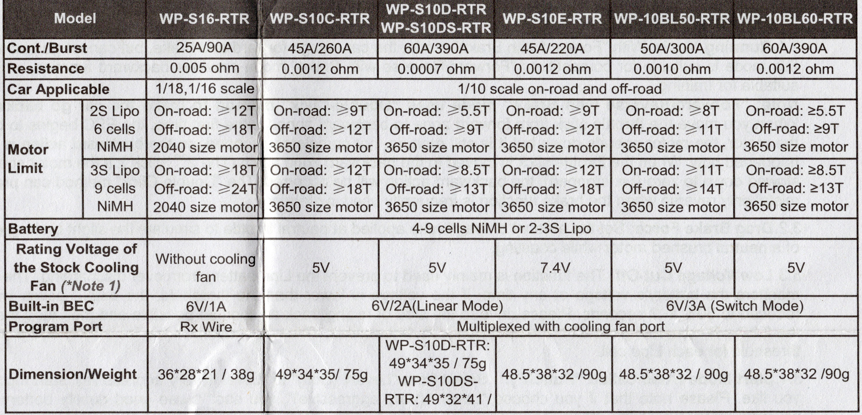
【SPECIFICATIONS】
Model
WP-S10C-RTR
WP-S16-RTR
Cont./Burst
25A/90A
45A/260A
0.005 ohm
Resistance
0.0012 ohm
1/18,1/16 scale
Car Applicable
On-road: ≥12T
On-road: ≥9T
2S Lipo
6 cells
Off-road: ≥18T
Off-road: ≥12T
NiMH
Motor
2040 size motor
3650 size motor
On-road: ≥18T
On-road: ≥12T
Limit
3S Lipo
9 cells
Off-road: ≥24T
Off-road: ≥18T
NiMH
2040 size motor
3650 size motor
Battery
4-9 cells NiMH or 2-3S Lipo
5V*
Rating Voltage of
Without cooling
the Stock Cooling
fan
* The stock 5V cooling fan only works with 2S Lipo or 4-6 cells NiMH.
Fan (*Note 1)
When using 3S Lipo or 7-9 cells NiMH, the stock 5V cooling fan MUST
Built-in BEC
6V/1A
Program Port
Rx Wire
Dimension/Weight
36*28*21 / 38g
49*34*35/ 75g
* Note1: Please remove the cooling fan when running the ESC in water. For more information about the 12V
cooling fan, please refer to the brief
introduction on page 3.
【BEGIN TO USE THE NEW ESC】
1. Connect the ESC, motor, receiver,
battery and servo according to the
following diagram
«+» and «-» wires of the ESC are
connected with the battery pack, and #A,
#B and #C are connected with the motor
wires. The «SET» button is used for
programming the ESC.
The control cable of the ESC (trio wires
with black, red and white color) is
connected with the throttle channel of the
receiver (Usually CH2).
1The #A, #B, #C wires of the ESC can be
connected with the motor wires freely
(without any order). If the motor runs in
HW-SM601ENG-20140903 Page — 1 —
WP-S10D-RTR
WP-S10DS-RTR
WP-10BL50-RTR
WP-S10E-RTR
WP-10BL60-RTR
50A/300A
60A/390A
45A/220A
0.0010 ohm
0.0007 ohm
0.0012 ohm
1/10 scale on-road and off-road
On-road: ≥8T
On-road: ≥5.5T
On-road: ≥9T
Off-road: ≥11T
Off-road: ≥9T
Off-road: ≥12T
3650 size motor
3650 size motor
3650 size motor
On-road: ≥11T
On-road: ≥8.5T
On-road: ≥12T
Off-road: ≥14T
Off-road: ≥13T
Off-road: ≥18T
3650 size motor
3650 size motor
3650 size motor
WP-S10D-RTR: 5V*
7.4V
WP-S10DS-RTR: 5V*
7.4V
WP-10BL60-RTR:7.4V
be replaced by 7.4V or 12V cololing fan.
6V/2A
Multiplexed with cooling fan port
WP-S10D-RTR:
49*34*35 / 75g
WP-S10DS-RTR:
48.5*38*32 / 90g
48.5*38*32 /90g
49*32*41 / 75g
WP-10BL60-RTR:
48.5*38*32 / 90g
User Manual of Water-Proof Brushless Speed Controller (RTR Version)
the opposite direction, please swap any two wire connections.
Note: You can use the transmitter to set the throttle channel to the»Reverse» direction, and then the motor
will run oppositely. Please calibrate the throttle range again after changing the direction of throttle
channel.
2. Throttle Range Setting (Throttle Range Calibration)
In order to make the ESC match the throttle range, you must calibrate it when you begin to use a new ESC, or a
new transmitter, or after changing the settings of the neutral position of throttle channel, ATV or EPA parameters,
otherwise the ESC cannot work properly.
There are 3 points need to be set, they are the top point of «forward»,» backward» and the neutral point.
The following pictures show how to set the throttle range with a Futaba
A) Switch off the ESC, turn on the
transmitter, set the direction of throttle
channel to «REV», set the «EPA/ATV»
value of throttle channel to «100%», and
disable the «ABS» brake function of
your transmitter.
(*Note2)
B) Hold the «SET» key and then switch on
the ESC, when the red LED begins to
flash, release the key immediately.
(Please check the picture on the right side)
C) Set the THREE points according to the
steps shown in the picture on the right
side.
1) Neutral point
2) End point of forward direction
3) End point of backward direction
D) When the process of calibration is
finished, the motor can be started after
3 seconds.
Note2: If you don’t release the «SET» key after the
red LED begins to flash, the ESC will enter the
program mode, in such a case, please switch off
the ESC and re-calibrate the throttle range again
from step A to step D.
3. The LED Status in Normal Running
a)
When the throttle stick is in the neutral range, neither the Red LED nor the Green LED lights up.
b)
When the car moves forward, the Red LED solidly lights; the Green LED also lights up when the throttle stick is
at the top position (100% throttle).
c)
When the car brakes, the Red LED solidly lights; the Green LED also lights up when the throttle stick is at the
bottom position and the maximum brake force is set to 100%.
d)
When the car reverses, the Red LED solidly lights.
【ALERT TONES】
1.
Input voltage abnormal alert tone: The ESC begins to check the input voltage when power on, if it is out of the
normal range, such an alert tone will be emitted: «beep-beep-, beep-beep-, beep-beep-» (There is 1 second
time interval between every «beep-beep-» tone).
2.
Throttle signal abnormal alert tone: When the ESC can’t detect the normal throttle signal, such an alert tone
will be emitted: «beep-, beep-, beep-» (There is 2 seconds time interval between every «beep-» tone).
【PROTECTION FUNCTION】
1.
Low voltage cut-off protection: If the voltage of a Lipo battery pack is lower than the threshold for 2 seconds,
the ESC will cut off the output power. Please note that the ESC cannot be restarted if the voltage of each Lipo
cell is lower than 3.5V.
For NiMH battery packs, if the voltage of the whole NiMH battery pack is higher than 9.0V but lower than 12V,
it will be considered as a 3S Lipo; If it is lower than 9.0V, it will be considered as a 2S Lipo. For example, if the
NiMH battery pack is 8.0V, and the threshold is set to 2.6V/Cell, it is considered as a 2S Lipo, and the
low-voltage cut-off threshold for this NiMH battery pack is 2.6*2=5.2V.
TM
transmitter.
2.
Over-heat protection: When the temperature of the ESC is over a factory preset threshold for 5 seconds, the
ESC will cut off the output power. You can disable the over-heat protection function for competition race.
3.
Throttle signal loss protection: The ESC will cut off the output power if the throttle signal is lost for 0.2 second.
【PROGRAM THE ESC】
1. Program Method
Note:
In the program process, the motor will emit «Beep» tone when the LED is flashing.
th
programmable item is represented by 5 short Beeps (that is, «BBBBB»).
The 5
For the options of each programmable item, we use a long time flash and long «Beep—» tone to represent
number «5», so it is easy to identify the options with big numbers.
For example, if the LED flashes as the following:
«A long time flash» (Motor sounds «B—«) = The option 5
«A long time flash + a short time flash» (Motor sounds «B—B») = The option 6
«A long time flash + 2 short times flash» (Motor sounds «B—BB») = The option 7
«A long time flash + 3 short times flash» (Motor sounds «B—BBB») = The option 8
HW-SM601ENG-20140903 Page — 2 —
| Параметры | Регуляторы скорости бесколлекторные |
Бесколлекторный регулятор скорости с вентилятором охлаждения WP-10BL50 на 50А и влагозащитой для автомоделей 10 масштаба.
Поддерживает 2-х и 3-х баночные Li-Po аккумуляторы на 7.4-11.1V
ВЕС: 6/3А
Таблица настройки регулятора HSP Racing:
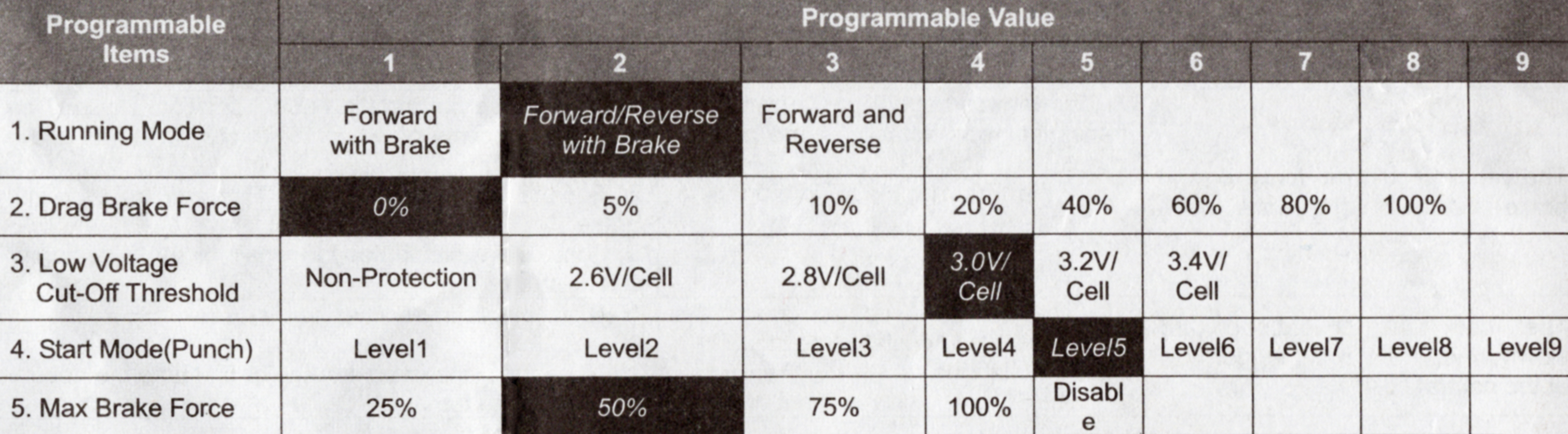
Таблица настройки регулятора BSD Racing:
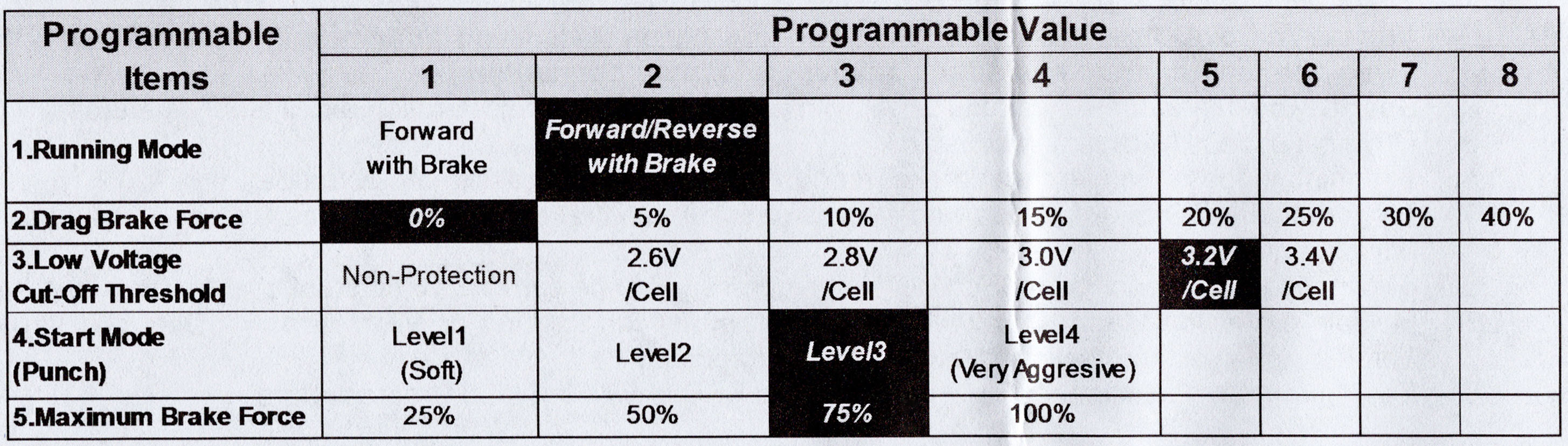
Таблица настройки регулятора Remo Hobby:

Таблица подбора моторов и аккумуляторов:
|
Detail Specifications: 1411/1411717-wp10bl50rtr.pdf file (17 Apr 2023) |
Accompanying Data:
Hobbywing WP-10BL50-RTR Controller PDF Operation & User’s Manual (Updated: Monday 17th of April 2023 06:21:34 PM)
Rating: 4.9 (rated by 90 users)
Compatible devices: XERUN-SCT PRO, FLYFUN 40A V5, EZRUN MAX10 SCT, XR10 STOCK SPEC, Platinum HV-200A-OPTO, HW-SM805DUL, QuicRun WP Crawler Brushed, Platinum 60A V4.
Recommended Documentation:
Text Version of Operation & User’s Manual
(Ocr-Read Summary of Contents, UPD: 17 April 2023)
-
1, User Manual of Water-Proof Brushless Speed Controller (RTR Version) HW-SM601ENG-…
-
2, User Manual of Water-Proof Brushless Speed Controller (RTR Version) HW-SM601ENG-20140903…
-
3, Hobbywing WP-10BL50-RTR User Manual of Water-Proof Brushless Speed Controller (RTR Version) HW-SM601ENG-20140903 Page …
Recommended Instructions:
A3100-16 DC EI, MONTE CARLO 1998, C9650dn, D-E226CK Primary, PowerConnect J-8208, AS-1725


-
www.deltaww.comAS Series Module ManualAS Series Module Manual2020/04/28Industrial Automation HeadquartersDelta Electronics, Inc. Taoyuan Technology CenterNo.18, Xinglong Rd., Taoyuan City, Taoyuan County 33068, TaiwanTEL: 886-3-362-6301 / FAX: 886-3-371-6301AsiaDelta Electronics (Jiangsu) Ltd.Wujiang Plant 31688 Jiangxing East Road, Wujiang Economic Development ZoneWujiang Cit …
AS Series 632
-
74 319 0172 0G2533xxde Installationsanleitung itIstruzioni di montaggio en Installation Instructions esInstrucciones de Montaje fr Instructions d’installation plInstrukcja montażu nl Installatievoorschriften csMontážní list OCI611… de Deutsch Montage Festlegen des Montageortes • In trockenem Raum • Einbaumöglichkeiten: − Kompaktstation − Schaltschrank …
OCI611 Series 20
-
F-35-60October 20181FEATURES• Safe start with DETECT-A-FLAME® flame sensing technology• Custom pre-purge and inter-purge timings*• Single or three trials for ignition•System diagnostic LED• Flame current test points• Local or remote flame sensing•Automatic reset**• Alarm output (normally closed contact)APPLICATIONS• Commercial cooking• Gas furnaces•Boiler …
35-60 Series 7
-
LC880 Experiment Controller User Guide Documentation for the LC880™ Controller and Trigger™ Control Software v. 5.0 Trigger software ©1996—2002 LabSmith. This manual ©2002 LabSmith. No part of this document may be reproduced or distributed without the consent of LabSmith. …
LC880 37
Additional Information:
Popular Right Now:
Operating Impressions, Questions and Answers:

User Manual of Water-Proof Brushless Speed Controller (RTR Version) HW-SM601ENG-20140903 Page — 1 —
USER MANUAL
WATER-PROOF
SENSORLESS BRUSHLESS
SPEED CONTROLLER
( RTR VERSION )
【DECLARATION】
Thanks for purchasing our electronic speed controller (ESC). The power system for RC model can be very
dangerous, so please read this manual carefully. In that we have no control over the correct use,
installation, application, or maintenance of our products, no liability shall be assumed nor accepted for
any damages, losses or costs resulting from the use of the product.
【FEATURES】
1. Water-proof and dust-proof. The ESC can work under water for a short time.
(Please remove the cooling fan when running car in water, and after running, please make the ESC
clean and then dry it to avoid the oxidation to copper connectors)
2. Specially designed for RC car and truck, with excellent start-up, acceleration and linearity features.
3. Drive sensorless brushless motors.
4. 2 running modes (“Forward with brake” mode, “Forward/Backward with brake” mode).
5. Proportional ABS brake function with 4 steps of maximum brake force adjustment, 8 steps of drag-brake force
adjustment.
6. 4 start modes (“Punch”) from “Soft” to “Very aggressive” to be suitable for different chassis, tires and tracks.
7. Multiple protection features: Low voltage cut-off protection for Lipo or NiMH battery / Over-heat protection /
Throttle signal loss protection / Motor blocked protection.
8. Easily programmed with the “SET” button on the ESC or with the LED Program Card.
【SPECIFICATIONS】
WP-S16-RTR WP-10BL50-RTR WP-S10E-RTR
0.005 ohm
0.0010 ohm 0.0012 ohm
36*28*21 / 38g 48.5*38*32 / 90g 48.5*38*32 /90g
WP-S10D-RTR
WP-S10DS-RTR
WP-10BL60-RTR
1/10 scale on-road and off-road
On-road: ≥9T
Off-road: ≥12T
3650 size motor
On-road: ≥5.5T
Off-road: ≥9T
3650 size motor
On-road: ≥9T
Off-road: ≥12T
3650 size motor
4-9 cells NiMH or 2-3S Lipo
Rating Voltage of
the Stock Cooling
Fan (*Note 1)
On-road: ≥12T
Off-road: ≥18T
2040 size motor
On-road: ≥18T
Off-road: ≥24T
2040 size motor
On-road: ≥12T
Off-road: ≥18T
3650 size motor
WP-S10D-RTR: 5V*
WP-S10DS-RTR: 5V*
WP-10BL60-RTR:7.4V
On-road: ≥8T
Off-road: ≥11T
3650 size motor
On-road: ≥11T
Off-road: ≥14T
3650 size motor
* The stock 5V cooling fan only works with 2S Lipo or 4-6 cells NiMH.
When using 3S Lipo or 7-9 cells NiMH, the stock 5V cooling fan MUST
be replaced by 7.4V or 12V cololing fan.
Multiplexed with cooling fan port
On-road: ≥12T
Off-road: ≥18T
3650 size motor
On-road: ≥8.5T
Off-road: ≥13T
3650 size motor
WP-S10D-RTR:
49*34*35 / 75g
WP-S10DS-RTR:
49*32*41 / 75g
WP-10BL60-RTR:
48.5*38*32 / 90g
* Note1: Please remove the cooling fan when running the ESC in water. For more information about the 12V
cooling fan, please refer to the brief
introduction on page 3.
【BEGIN TO USE THE NEW ESC】
1. Connect the ESC, motor, receiver,
battery and servo according to the
following diagram
“+” and “—” wires of the ESC are
connected with the battery pack, and #A,
#B and #C are connected with the motor
wires. The “SET” button is used for
programming the ESC.
The control cable of the ESC (trio wires
with black, red and white color) is
connected with the throttle channel of the
receiver (Usually CH2).
1The #A, #B, #C wires of the ESC can be
connected with the motor wires freely
(without any order). If the motor runs in