1 Port ADSL2+Router
User Manual
i
Contents
1. Introduction ……………………………………………………………………………………………………………………………………………… 1
1.1 Package List …………………………………………………………………………………………………………………………………….. 1
1.2 Safety Cautions ………………………………………………………………………………………………………………………………… 1
1.3 LED and Interface Description…………………………………………………………………………………………………………….. 2
1.4 System Requirements ………………………………………………………………………………………………………………………… 3
1.5 Feature ……………………………………………………………………………………………………………………………………………. 3
1.6 FCC Compliance ………………………………………………………………………………………………………………………………. 4
1.7 Supporting Protocols …………………………………………………………………………………………………………………………. 4
2. Hardware Installation …………………………………………………………………………………………………………………………………. 5
3. Introducing Web Configuration ……………………………………………………………………………………………………………………. 7
3.1 How to access Router ………………………………………………………………………………………………………………………… 7
3.2 Status ……………………………………………………………………………………………………………………………………………… 8
3.2.1 System …………………………………………………………………………………………………………………………………… 8
3.2.2 LAN ……………………………………………………………………………………………………………………………………… 9
3.2.3 WAN…………………………………………………………………………………………………………………………………… 10
3.2.4 Statistic………………………………………………………………………………………………………………………………… 10
3.2.4.1 Traffic Statistic……………………………………………………………………………………………………………………. 10
3.2.4.2 DSL Statistic………………………………………………………………………………………………………………………. 11
3.2.5 ARP Table ……………………………………………………………………………………………………………………………. 12
3.3 Wizard ………………………………………………………………………………………………………………………………………….. 12
3.3.1 Wizard…………………………………………………………………………………………………………………………………. 12
3.4 LAN……………………………………………………………………………………………………………………………………………… 20
3.4.1 LAN Settings ………………………………………………………………………………………………………………………… 20
3.4.2 DHCP Settings………………………………………………………………………………………………………………………. 21
3.5 WAN ……………………………………………………………………………………………………………………………………………. 25
3.5.1 WAN Interface………………………………………………………………………………………………………………………. 26
3.5.2 ATM Settings ……………………………………………………………………………………………………………………….. 28
3.5.3 ADSL Settings………………………………………………………………………………………………………………………. 29
3.6 Advance ………………………………………………………………………………………………………………………………………… 30
3.6.1 DNS ……………………………………………………………………………………………………………………………………. 30
3.6.1.1 DNS Server………………………………………………………………………………………………………………………… 30
3.6.1.2 DDNS……………………………………………………………………………………………………………………………….. 31
3.6.2 Firewall ……………………………………………………………………………………………………………………………….. 32 ii
3.6.2.1 IPPort Filter ………………………………………………………………………………………………………………………. 32
3.6.2.2 MAC Filter ………………………………………………………………………………………………………………………… 33
3.6.2.3 URL Blocking…………………………………………………………………………………………………………………….. 34
3.6.3 Virtual Server ……………………………………………………………………………………………………………………….. 35
3.6.3.1 Services …………………………………………………………………………………………………………………………….. 35
3.6.3.2 DMZ Settings……………………………………………………………………………………………………………………… 36
3.6.4 Routing………………………………………………………………………………………………………………………………… 37
3.6.4.1 RIP …………………………………………………………………………………………………………………………………… 37
3.6.4.2 Static Route………………………………………………………………………………………………………………………… 38
3.6.5 IP QoS …………………………………………………………………………………………………………………………………. 39
3.6.6 Other …………………………………………………………………………………………………………………………………… 39
3.6.6.1 IGMP Proxy……………………………………………………………………………………………………………………….. 40
3.6.6.2 UPNP………………………………………………………………………………………………………………………………… 40
3.6.6.3 Bridge……………………………………………………………………………………………………………………………….. 41
3.6.6.4 IP PassThrough …………………………………………………………………………………………………………………… 42
3.7 Admin …………………………………………………………………………………………………………………………………………… 42
3.7.1 Remote Access………………………………………………………………………………………………………………………. 42
3.7.2 Commit/Reboot……………………………………………………………………………………………………………………… 43
3.7.3 Password………………………………………………………………………………………………………………………………. 43
3.7.4 Backup/Restore……………………………………………………………………………………………………………………… 44
3.7.5 Upgrade Fireware…………………………………………………………………………………………………………………… 45
3.7.6 Time Zone ……………………………………………………………………………………………………………………………. 45
3.7.7 SNMP………………………………………………………………………………………………………………………………….. 46
3.7.8 TR069………………………………………………………………………………………………………………………………….. 47
3.7.9 ACL ……………………………………………………………………………………………………………………………………. 48
3.8 Diagnostic ……………………………………………………………………………………………………………………………………… 49
3.8.1 Ping …………………………………………………………………………………………………………………………………….. 49
3.8.2 ATM Loopback……………………………………………………………………………………………………………………… 50
3.8.3 ADSL ………………………………………………………………………………………………………………………………….. 50
3.8.4 Diagnostic…………………………………………………………………………………………………………………………….. 51
APPENDIX B: Abbreviation ………………………………………………………………………………………………………………….. 51 iii
1. Introduction
The ADSL access device supports multiple line modes. It provides one 10/100Base-T Ethernet interface at the user end. Utilizing the high-speed ADSL connection, the device provide users with broadband connectivity to the Internet or the Intranet for high-end users as net bars, office users, etc. can provide a downlink speed up to 24 Mbit/s and uplink speed up to 1 Mbit/s.
1.1 Package List
l One single port router l One external splitter l One power adapter l Two pieces of telephone lines(RJ-11,more than 1m) l One piece of Ethernet cable(RJ-45, more than 1.5m) l One copy of User’s Manual l A centificate of quality l One copy of driver and utility software CD(optional)
1.2 Safety Cautions
Follow these announcements below to pretect the device from risks and damage caused by fire or electric power.
4 Use volume labels to mark the type of power.
4 Use the power adapter packed within the device package.
4 Pay attention to the power load of the outlet or prolonged lines. An overburden power outlet or damaged lines and plugs may cause electric shock or fire accident. Check the power cords regularly. If you find any damage, replace it at once.
4 Proper space left for heat radiation is necessary to avoid any damage caused by overheating to the device. The long and thin holes on the Access Point are designed for heat radiation to make sure the device works normally. Don’t cover these heat radiant holes.
4 Do not put this device close to a place where a heat source exits or high temperature occurs. Avoid the device from direct sunshine.
4 Do not put this device close to a place where is over damp or watery. Do not spill any fluid on this device.
4 Do not connect this device to any PC or electronic product, unless our customer engineer or your broadband provider instructs you to do this, because any wrong connection may cause any power or fire risk.
4 Do not place this device on an unstable surface or support.
1
1.3 LED and Interface Description
Front panel
Fig 1.3-1 Front panel
LED
POWER
Link
Data
Ethernet
Color Status
Green
Descriptions
Green/Red
Green
OFF
GREEN
RED
RED
BLINK
OFF
BLINK
ON
Green
No power
Device init OK
Device init
Fireware upgrade
Initial self-test failed
Device is detecting itself
Initial self-test of the unit is OK and ready
OFF Internet connection failed
BLINK Internet data transiting
ON Internet connection OK
OFF No LAN link
BLINK LAN data transiting
ON LAN link established and active
Rear panel
Items
DSL
Fig 1.3-2 Rear panel
Usage
Line RJ-11 port
2
Items Usage
Reset
Resets to factory defaults. To restore factory defaults, keep the device powered on and push a paper clip in to the hole.
Press down the button over 5 seconds and then release.
Ethernet Ethernet RJ-45 port
PWR
Power On/Off.
Power connector. DC 10 Voltage/1000mA,female pole is positive.
1.4 System Requirements
Make sure first that you have prepared these following items to guarantee the ROUTER can work normally.
4 Services subscriptions
4 An 10BaseT/100BaseT Ethernet card installed on your PC
4 HUB or Switch. (Attached to several PCs through one of Ethernet interfaces on the device)
4 Operation system: Windows 98SE, Windows 2000, Windows ME, or Windows XP
4 Internet Explorer V5.0 or higher, or Netscape V4.0 or higher, or firefox 1.5 or higher.
1.5 Feature
4 Supports various line modes
4 Supports external PPPoE dial-up access
4 Supports internal PPPoE/PPPoA dial-up access
4 Supports leased line mode
4 Supports ZIPB (Zero Installation PPP Bridge Mode)
4 Supports 1483B/1483R/MER access
4 Supports multiple PVCs(eight at most) and these PVCs can be isolated from each other
4 Support a single PVC with multiple sessions
4 Support multiple PVCs with multiple sessions
4 Supports the binding of the ports and the PVCs
4 Supports the 802.1Q and 802.1P protocol
4 Supports DHCP server
4 Supports NAT/NAPT
4 Supports static route
4 Supports firmware upgrade:WEB/tftp/ftp
4 Supports reset to factory default:reset, WEB
4 Supports DNS relay
4 Supports Virtual server
4 Supports DMZ functions
4 Supports two-grade passwords and usernames
4 Supports WEB interface
4 Supports telnet CLI
4 Supports System status display
3
4 Supports PPP session PAP/CHAP
4 Supports IP filter function
4 Supports remote access control
4 Supports line connection status test
4 Supports remote management(Telnet; HTTP)
4 Supports configuration file backup and restoration function
4 Ethernet supported such as Crossover Detection & Auto-Correction and polarity correction
4 Supports UPnP
1.6 FCC Compliance
This equipment has been tested and found to comply with the limits for Class digital devices pursuant to part 15 of the FCC Rules. These limits are designed to provide reasonable protection against harmful interference when the equipment is operated in a commercial environment.
This equipment generates, uses, and can radiate radio frequency energy and, if not installed and used in accordance with the instruction manual, may cause harmful interference to radio communication.
Operation of this equipment in residential area is likely to cause harmful interference in which case the user will be required to correct the interference at this own expense.
The user should not modify or change this equipment without written approval from company name.
Modification could void authority to use this equipment.
For the safety reason, people should not work in a situation which RF Exposure limits be exceeded. To prevent the situation happening, people who work with the antenna should be aware of the following rules:
1. Install the antenna in a location where a distance of 20cm from the antenna may be maintained.
2. While installing the antenna in the location, please do not turn on the power of wireless card.
3. While the device is working, please do not contact the antenna.
1.7 Supporting Protocols
ITU G.992.1 (G.DMT) Annex A
4 ITU G.992.2 (G.LITE)
4 ANSI T1.413 Issue 2
4 ITU G.992.3 (ADSL2)
4 ITU G.992.5 (ADSL2+)
4
2. Hardware Installation
1、Refer to the figure below: Connect the DSL port of the device and the ROUTER port of the splitter with a telephone cable; connect the phone to the Phone port of the splitter through a cable; connect the incoming line to the Line port of the splitter.
The splitter has three ports:
LINE: Connects to a wall phone jack (RJ-11 jack)
ROUTER: Connects to the DSL jack of the device
PHONE: Connects to a telephone set
2、Connect the LAN port of the device to the network card of the PC via an Ethernet line (MDI/MDIX).
Note: Use twisted-pair cables to connect with the HUB/Switch.
3、Plug the power adapter to the wall outlet and then connect the other end of it to the PWR port of the device.
Connection 1: Fig. 2-1 displays the application diagram for the connection of the Router, PC, splitter and telephone set。
Fig 2-1 Connection Diagram(Without connecting telephone sets before the splitter)
Connection 2:As illustrated in the following figure, the splitter is installed close to the device.
5
Fig 2-2 Connection Diagram(Connecting a telephone set before the splitter) l It is recommended to follow the Connection 1 in an actual connection! l Note: When Connection 2 is used, the filter must be installed close to the telephone lines. (See Fig.
2-2. Do not use the splitter instead of the filter).
Installing a telephone directly before the splitter may lead to a failure of connection between the device and the device of LAN side, or cannot access into the Internet, or slow the connection speed if you really need to add a telephone set before the splitter, you have to add a MicroFilter before connecting to a telephone set.
Do not connect several telephones before the splitter. Moreover, do not connect several telephones with
MicroFilters.
6
3. Introducing Web Configuration
3.1 How to access Router
The following introductions are prepared for the first time users, it is a detail “How-To” user guide.
1、 Open IE browser,then enter http://192.168.1.1
in address bar.
2、 You are required to enter user name and password. See the Fig 3.2-1. l The super user name and password is admin/admin l The common user name and password is user/user
Fig 3.1-1
3、 If you enter as super user, the below screen will be displayed when you enter successfully.
7
Fig 3.1-2
After you enter router as super user, you can check, config and modify all the options. You can use the system diagnostic function also.
If you enter as common user, you can check the status of ROUTER, but can’t change the most of options.
3.2 Status
Click Status in the menu to open the sub-menu which contains 5 items: System, LAN, WAN, Statistic and
ARP Table.
3.2.1 System
Click System in the sub-menu to open the screen of Fig 3.2.1. In this page, you can view the current status and some basic settings of this router, for example, Software Version, DSL mode, Upstream Speed,
Downstream Speed, Uptime and so on.
8
Fig 3.2.1
3.2.2 LAN
Click LAN in the sub-menu to open the screen of Fig 3.2.2. In this page, you can view the LAN IP, DHCP
Server status, MAC Address and DHCP Client Table. If you want to config the LAN network, refer to chapter 3.4.1 “LAN Settings”.
Fig 3.2.2
9
3.2.3 WAN
Click WAN in the sub-menu to open the screen of Fig 3.2.3. In this page, you can view basic status of WAN,
Default Gateway, DNS Server, ect. . If you want to config the WAN network, refer to chapter 3.5.1 “WAN
Interface”.
Fig 3.2.3
3.2.4 Statistic
Click Statistic in the sub-menu to open the menu in the left bar, whick contains two items:Traffic Statistic and DSL Statistic.
3.2.4.1 Traffic Statistic
Click Traffic Statistic in the left bar to open the screen of Fig 3.2.4.1. In this page, you can view the statistics of each network port.
10
Fig 3.2.4.1
3.2.4.2 DSL Statistic
Click DSL Statistic in the left bar to open the screen of Fig 3.2.4.2. In this page, you can view the
ADSL line statistics, downstream rate, upstream rate, ect. .
Fig 3.2.4.2
11
3.2.5 ARP Table
Click ARP Table in the sub-menu to open the screen of Fig 3.2.5. In this page, you can view the talbe which shows a list of learned MAC addresses.
Fig 3.2.5
3.3 Wizard
Click Wizard in the menu to open the sub-menu which contains one item: Wizard.
3.3.1 Wizard
Wizard enables speedy and accurate configuration of your Internet connection and other important parameters. The following sections describe these various configuration parameters. Whether you configure these parameters or use the default ones, click ‘Next’ to enable your Internet connection.
When subscribing to a broadband service, you should be aware of the method by which you are connected to the Internet. Your physical WAN device can be either Ethernet, DSL, or both. Technical information regarding the properties of your Internet connection should be provided by your Internet Service Provider
(ISP). For example, your ISP should inform you whether you are connected to the Internet using a static or dynamic IP address, or what protocols, such as PPPOA or PPPoE, you will be using to communicate over the Internet.
Click Wizard in the sub-menu to open the screen of Fig 3.3.1-1. In this page, you can config the VPI/VCI number.
12
Fig 3.3.1-1
Be sure to use the correct Virtual Path Identifier(VPI) and Virtual Channel Identifier(VCI) numbers assigned to you. The valid range for VPI is 0 to 255 and for VCI is 1 to 65535.
Then press Next, the Fig 3.3.1-2 screen will appear. In this page, you can select the WAN Connect Type and the encapsulation method.
Fig 3.3.1-2
13
The following table describes the fields in this screen.
Label
WAN Connection Type
Encapsulation Mode
< Back
Next >
Description
Select the WAN Connection Type here, you can select PPPoA, PPPoE,
1483 MER, 1483 Routed or 1483 Bridged.
Select the method of encapsulation used by your ISP from the drop-down list box. Choises are LLC/SNAP or VC-Mux.
Click < Back to return to the previous screen
Click Next > to go to the next screen
If you select PPPoA or PPPoE in WAN Connection Type, click Next, the screen of Fig 3.3.1-3 appears as shown next.
Label
Obtain an IP address automatically
Use the following IP address
WAN IP Address
Enable NAT
Fig 3.3.1-3
The following table describes the fields of this screen.
Description
The dynamic IP is not fixed; your ISP assigns you the different one each time.
A static IP is a fixed IP that your ISP gives you.
< Back
Next >
Input the IP address of the WAN interface provided by your ISP
Select it to enable the NAT functions of the MODEM. If you are not to enable NAT and intend the user of the MODEM to access the Internet normally, you must add a route on the uplink equipment; otherwise the access to the Internet will fail. Normally, it is required to enable NAT.
Click < Back to return to the previous screen
Click Next > to go to the next screen
Then click Next, the screen of Fig3.3.1-4 appears as shown next.
14
Fig
3.3.1-4
The following table describes the fields of this screen.
Label
PPP Username
PPP Password
PPP Connection Type
< Back
Next >
Description
The username and password apply to PPPoE and PPPoA encapsulation only. Make sure that you have entered the correct username and password.
Choices are Continuous, Connect on Demand and Manual.
Click < Back to return to the previous screen
Click Next > to go to the next screen
Then click Next, the screen of Fig3.3.1-5 appears as shown next.
15
Fig
3.3.1-5
The following table describes the fields of this screen.
Label Description
LAN IP
Enable DHCP Server
Start IP
End IP
Enter the IP address of your ROUTER in dotted decimal notation, for example, 192.168.1.1(factory default)
LAN Netmask
Enable Secondary IP
Type the subnet mask of LAN IP.
Select this check box to enable the secondary LAN IP
Secondary LAN IP Enter the secondary IP address of your ROUTER in dotted decimal notation, for example, 192.168.100.1(factory default)
Secondary LAN Netmask Type the subnet mask of the secondary LAN IP
Select this check box to enable the DHCP Server
This field specifies the first of the contiguous addresses in the IP address pool.
This field specifies the last of the contiguous addresses in the IP address pool.
< Back
Next >
Click < Back to return to the previous screen
Click Next > to go to the next screen
If you finish the settings of this page, click Next, the screen appears as shown next.
16
Fig 3.3.1-7
If you select 1483 MER in Fig 3.3.1-2, the screen appears as shown next.
Fig 3.3.1-8
17
The following table describes the fields of this screen.
Label
Obtain an IP address automatically
Use the following IP address
WAN IP Address
WAN Subnet Mask
Default Gateway
Obtain DNS server addresses automatically
Use the following DNS server addresses
Primary DNS server
Secondary DNS server
Enable NAT
< Back
Next >
Description
The MODEM will obtain a (WAN) IP address automatically and at this time it will enable DHCP Client functions. The WAN IP address is obtained from the uplink equipment like BAS and the uplink equipment is required to enable the DHCP Server functions.
If you want to input the WAN ip address by yourself. Check this entry and then input related data in the field.
Input the IP address of the WAN interface provided by your ISP
Input the subnet mask concerned to the IP address of the WAN interface provided by your ISP.
You can input the IP address of the default gateway by yourself, click this entry and then input related data in the fields.
To obtain the IP address of the DNS server assigned by the uplink equipment such as BAS.
If you want to input the IP address of the DNS server by yourself, click this entry and then input related data in the fields.
Input the IP address of the primary DNS server here.
Input the IP address of the secondary DNS server provided by your ISP here.
Select it to enable the NAT functions of the MODEM. If you are not to enable NAT and intend the user of the MODEM to access the Internet normally, you must add a route on the uplink equipment; otherwise the access to the Internet will fail. Normally, it is required to enable NAT.
Click < Back to return to the previous screen
Click Next > to go to the next screen
If you finish the settings of this page, click Next, the screen of Fig 3.3.1-6 appears. The settings of this screen, see above paragraphs.
If you select 1483 Routed in Fig 3.3.1-2, the screen of Fig 3.3.1-9 appears as shown next.
18
Label
None
Obtain an IP address automatically
Use the following IP address
WAN IP Address
WAN Subnet Mask
Fig 3.3.1-9
The following table describes the fields of this screen.
Description
The dynamic IP is not fixed; your ISP assigns you the different one each time.
A static IP is a fixed IP that your ISP gives you.
Obtain DNS server addresses automatically
Use the following DNS server addresses
Primary DNS server
Secondary DNS server
Enable NAT
< Back
Next >
Input the IP address of the WAN interface provided by your ISP
Input the subnet mask concerned to the IP address of the WAN interface provided by your ISP.
To obtain the IP address of the DNS server assigned by the uplink equipment such as BAS.
If you want to input the IP address of the DNS server by yourself, click this entry and then input related data in the fields.
Input the IP address of the primary DNS server here.
Input the IP address of the secondary DNS server provided by your ISP here.
Select it to enable the NAT functions of the MODEM. If you are not to enable NAT and intend the user of the MODEM to access the Internet normally, you must add a route on the uplink equipment; otherwise the access to the Internet will fail. Normally, it is required to enable NAT.
Click < Back to return to the previous screen
Click Next > to go to the next screen
19
3.4 LAN
Click LAN in the menu to open the sub-menu which contains 2 items: LAN Settings and DHCP Settings.
You can use the LAN configuration to define an IP address for the DSL Router and configure the DHCP server.
3.4.1 LAN Settings
On this screen you can change the device’s IP address. The preset IP address is 192.168.1.1. This is the
Private IP address of the DSL Router. This is the address under which the device can be reached in the local network. It can be freely assigned from the block of available addresses.
Click LAN Settings in the sub-menu to open the screen of Fig 3.4.1. In this page you can config the LAN network.
Fig 3.4.1
The following table describes the fields of this screen.
Label
IP Address
Subnet Mask
Description
Input the IP of Local area network interface here.
We recommend that you use an address from a block that is reserved for private use. This address block is 192.168.1.1- 192.168.255.254
20
Secondary IP
Apply Changes
Select this checkbox to enable the secondary LAN IP. The two LAN IP must be in the different network.
Click this button to save the settings of this page.
3.4.2 DHCP Settings
DHCP(Dynamic Host Configuration Protocol) allows the individual client(computers) to obain the TCP/IP configuration at start-up from the centralize DHCP server. You can configure this router as a DHCP server or disable it. DHCP server can assign IP address, an IP default gateway and DNS server to DHCP clients.
This router can also act as a surrogate DHCP server(DHCP Proxy) where it relays IP address assignment from a actual real DHCP server to clients.
If the DHCP was disabled, the screen of Fig 3.4.2-1 appears. You can enable/disable DHCP Server or
DHCP Proxy.
Fig 3.4.2-1
If you set to DHCP Proxy, the screen of Fig 3.4.2-2 appears.
21
Fig 3.4.2-2
The following table describes the fields of this screen.
Label
DHCP Proxy
DHCP Server Address
Apply Changes
Description
If set to DHCP Proxy, your ROUTER acts a surrogate DHCP Server and relays the DHCP requests and reponses between the remote server and the client.
Enter the IP address of the actual, remote DHCP server in this field.
Click this button to save the changes of this page.
If you set to DHCP Server, the screen of Fig3.4.2-3 appears as shown next.
22
Fig 3.4.2-3
The following table describes the fields in this screen.
Label
DHCP Server
IP Pool Range
Show Client
Max Lease Time
Domain Name
Gateway Address
MAC-Base Assignment
Description
If set to DHCP Server, your ROUTER can assign IP addresses, an IP default gateway and DNS Servers to Windows95, Windows NT and other systems that support the DHCP client.
This field specifies the first and the last of contiguous IP address of the IP address pool.
Click this button, the screen of Fig 3.5.2-4 appears, which shows the assigned IP address of the clients.
The Lease time determines the period for which the PCs retain the IP addresses assigned to them without changing them.
Input the domain name here if you know. If you leave this blank, the domain name obtained by DHCP from the ISP is used. While you must enter host name(System Name) on each individual computer, the domain name can be assigned from this router via DHCP server.
Enter the IP default gateway of the IP address pool.
Click this button, the screen of Fig3.5.2-5 appears. This function allows you assign IP addresses on the LAN to specific individual computers based on their MAC address.
23
Apply Changes Click this button to save the changes of this page.
Click Show Client, the following window appears. In this window, you can view the IP address assigned to each DHCP client.
Fig 3.4.2-4
The following table describes the fields in this screen.
Label
IP Address
MAC Address
Time Expired(s)
Description
This field displays the IP address relative to the MAC address.
This field displays the MAC(Media Access Control) address of the computer.
Every Ethernet device has a unique MAC address. The MAC address is assigned at the factory and consists of six pairs of hexadecimal character, for example, 00-A0-C5-00-02-12.
Here shows the lease time. The Lease time determines the period for which the PCs retain the IP addresses assigned to them without changing them.
Click this button to refresh the Active DHCP Client Table.
Click this button to close this window.
Refresh
Close
Click MAC-Base Assignment button, the below window appears. In this page, you can assign IP addresses on the LAN to specific individual computers based on their MAC address.
24
Fig 3.4.2-5
The following table describes the fields of this screen.
Label
Host MAC Address
Assigned IP Address
Assign IP
Modify Assigned IP
Delete Assigned IP
Close
MAC-Base Assignment
Table
Description
Type the MAC address of a computer on your LAN
This field specifics the IP of the IP address pool.
Click this button after entered Host MAC Address and Assigned IP
Address, a row will be added in MAC-Base Assignment Table.
Select a row in MAC-Base Assignment Table, the MAC address and IP address will appears Host MAC Address and Assigned IP Address.
After modified the MAC Address and IP Address, click this button to save the changes.
Select a row in MAC-Base Assignment Table, then click this button, this row will be deleted.
Click this button to close this window.
This table shows the assigned IP address based on the MAC address.
3.5 WAN
Click WAN Interface in the menu to open the sub-menu which contains 3 items: WAN Interface、ATM
Settings and ADSL Settings.
25
3.5.1 WAN Interface
Click WAN Interface in the sub-menu to open the screen of Fig 3.5.1-1. In this page, you can configure
WAN Interface of your router.
Label
VPI
VCI
Encapsulation
Channel Mode
Admin Status
Enable NAPT
PPP Settings
Login Name
Password
Connection Type
Fig 3.5.1-1
Description
(Virtual Path Identifier) The virtual path between two points in an ATM network, and its valid value is from 0 to 255
The virtual channel between two points in an ATM network, ranging from
32 to 65535 (1 to 31 are reserved for known protocols)
Choices are LLC and VC-Mux.
There are five choices: 1483 Bridged, 1483 MER, PPPoE, PPPoA and
1483 Routed.
If select Disable, this PVC will be unusable.
Select it to enable the NAPT functions of the MODEM. If you are not to enable NAPT and intend the user of the MODEM to access the Internet normally, you must add a route on the uplink equipment; otherwise the access to the Internet will fail. Normally, it is required to enable NAPT.
The correct user name that your ISP has provided to you.
The correct password that your ISP has provided to you
The choices are Continuous, Connect on Demand and Manual.
26
Idle Time(min)
WAN IP Settings
Type
Local IP Address
Remote IP Address
Subnet Mask
Unnumbered
Default Route
Add
Modify
Delete Selected
If select Connect on Demand, you need to input the idle timeout time.
Within the preset minutes, if the MODEM doesn’t detect the flow of the user continuously, the MODEM will automatically disconnect the PPPOE connection.
The choices are Fixed IP and Use DHCP. If set Fixed IP, you should enter the Local IP Address, Remote IP Address and Subnet Mask. If set
Use DHCP, your MODEM will be a DHCP client, the WAN IP will be assigned by the remote DHCP server.
This is the IP of WAN interface which is provided by your ISP.
This is the gateway IP which is provided by your ISP.
This is the Subnet Mask of the Local IP Address.
Select this checkbox to enable IP Unnumbered function.
After configuring the parameters of this page, click this button then a new
PVC will be added into Current ATM VC Table.
Select a PVC in the Current ATM VC Table, then modify the parameters of this PVC. When you finish, click this button to apply the change of this
PVC.
Select a PVC in the Current ATM VC Table, then click this button to delete this PVC.
Click this button, the following screens will appear. In these pages, you can modify the PVCs’ parameters.
If the PVC uses PPPoE mode, click , the Fig 3.5.1-2 will appear. In this page, you can configure this
PPPoE PVC’s parameters.
27
Fig 3.5.1-2
3.5.2 ATM Settings
Click ATM Setting, the screen of Fig 3.5.1-3 will appear. In this page, you can configure the parameters of the ATM for your ADSL router, include QoS type, PCR, CDVT, SCR and MBS.
28
Fig 3.5.1-3
3.5.3 ADSL Settings
Click ADSL Interface in the sub-menu to open the screen of Fig 3.5.2. In this page, you can select the DSL modulation. Mostly, the user just need to remain this factory default setting. Our modem support these modulations: G.Dmt, G.lite, T1.413, ADSL2, ADSL2+, AnnexL and AnnexM. The router will negotiate the modulation mode with the DSLAM.
29
Fig 3.5.2
3.6 Advance
Click Advance in the menu to open the sub-menu which contains 6 items: DNS, Firewall, Virtual Server,
Routing, IP QOS, and Others.
3.6.1 DNS
Click DNS in the sub-menu to open the menu in the left bar, whick contains two items:DNS Server and DDNS.
3.6.1.1 DNS Server
Short for Domain Name System (or Service or Server), an Internet service that translates domain names into
IP addresses. Because domain names are alphabetic, they’re easier to remember. The Internet however, is really based on IP addresses. Every time you use a domain name, therefore, a DNS service must translate the name into the corresponding IP address. For example, the domain name www.example.com might translate to 198.105.232.4.
The DNS system is, in fact, its own network. If one DNS server doesn’t know how to translate a particular domain name, it asks another one, and so on, until the correct IP address is returned.
30
Click DNS Server in the left bar to open the screen of Fig 3.6.1.1.
Fig 3.6.1.1
Label Description
Attain DNS Automatically When this checkbox is selected, this router will accept the first received
DNS assignment from one of the PPPoA, PPPoE or MER enabled PVC(s) during the connection establishment.
Set DNS Manually When this checkbox is selected, please enter the primary and optional secondary DNS server IP addresses.
Apply Changes
Reset Selected
Click this button to save the settings of this page.
Click this button to begin configuring this screen afresh.
3.6.1.2 DDNS
Click DDNS in the left pane to open the screen of Fig 3.6.1.2.
31
Fig 3.6.1.2
3.6.2 Firewall
Click Firewall in the sub-menu to open the menu in the left bar, whick contains three items:IPPort Fileter,
MAC Filter and URL Blocking.
3.6.2.1 IPPort Filter
Click IPPort Filter in the left bar to open the screen of Fig 3.6.2.1. Entries in this table are used to restrict certain types of data packets through the Gateway. Use of such filters can be helpful in securing or restricting your local network.
Click the button Apply Changes to save the settings of this page.
Click the button Add to add a new rule of the IPPort Filter.
32
Fig 3.6.2.1
3.6.2.2 MAC Filter
Click MAC Filter in the left bar to open the screen of Fig 3.6.2.2. Entries in this table are used to restrict certain types of data packets from your local network to Internet through the Gateway. Use of such filters can be helpful in securing or restricting your local network.
Click the button Apply Changes to save the settings of this page.
Click the button Add to add a new rule of the MAC Filter.
33
Fig 3.6.2.2
3.6.2.3 URL Blocking
Click URL Blocking in the left bar to open the screen of Fig 3.6.2.3. This page is used to configure the
Blocked FQDN(Such as tw.yahoo.com) and filtered keyword. Here you can add/delete FQDN and filtered keyword.
34
Fig 3.6.2.3
3.6.3 Virtual Server
Click Virtual Server in the sub-menu to open the menu in the left bar,whick contains two items:Services and DMZ Settings.
3.6.3.1 Services
Click Services in the left pane to open the screen of Fig 3.6.3.1. This page is used to enable the servers in the local network.
Click the button Add to add a virtual server.
35
Fig 3.6.3.1
3.6.3.2 DMZ Settings
Click DMZ Settings in the left bar to open the screen of Fig 3.6.3.2. A Demilitarized Zone is used to provide Internet services without sacrificing unauthorized access to its local private network. Typically, the
DMZ host contains devices accessible to Internet traffic, such as Web (HTTP ) servers, FTP servers, SMTP
(e-mail) servers and DNS servers.
Select the checkbox Enable DMZ to enable this function. Then input a IP Address of the DMZ host.
Click the button Apply Changes to save the settings of this page.
36
Fig 3.6.3.2
3.6.4 Routing
Click Routing in the sub-menu to open the menu in the left bar, whick contains two items:RIP and Static
Route.
3.6.4.1 RIP
Click RIP in the left bar to open the screen of Fig 3.6.4.1. Enable the RIP if you are using this device as a
RIP-enabled router to communicate with others using the Routing Information Protocol. This page is used to select the interfaces on your deviceis that use RIP, and the version of the protocol used.
37
Fig 3.6.4.1
3.6.4.2 Static Route
Click Static Route in the left bar to open the screen of Fig 3.6.4.2-1. This page is used to configure the routing information. Here you can add/delete IP routes.
Fig 3.6.4.2-1
Click the button Show Routes, the below window will appear. The table shows a list of destination routes commonly accessed by your network.
Fig 3.6.4.2-2
38
3.6.5 IP QoS
Click IP QoS in the sub-menu to open the screen of Fig 3.6.5. Entries in this table are used to assign the precedence for each incoming packet based on physical LAN port, TCP/UDP port number, and source/destination IP address/subnet masks.
Click the button Apply Changes to save the settings of this page.
Fig 3.6.5
3.6.6 Other
Click Others in the sub-menu to open the menu in the left bar,whick contains four items:IGMP Proxy,
UPNP, Bridge and IP PassThrough.
39
3.6.6.1 IGMP Proxy
Click IGMP Proxy in the left bar to open the screen of Fig 3.6.6.1. IGMP proxy enables the system to issue
IGMP host messages on behalf of hosts that the system discovered through standard IGMP interfaces. The system acts as a proxy for its hosts after you enable it.
Click Apply Changes to save the settings of this page.
Fig 3.6.6.1
3.6.6.2 UPNP
Click UPNP in the left bar to open the screen of Fig 3.6.6.2. This page is used to configure UPnP. The system acts as a daemon after you enable it.
Click Apply Changes to save the settings of this page.
40
Fig 3.6.6.2
3.6.6.3 Bridge
Click Bridge in the left bar to open the screen of Fig 3.6.6.3-1. This page is used to configure the bridge parameters. Here you can change the settings or view some information on the bridge and its attached ports.
Fig 3.6.6.3-1
Click Show MACs button in Fig 3.6.6.3-1, the below window will appear. This table shows a list of learned MAC addresses for this bridge.
Fig 3.6.6.3-2
41
3.6.6.4 IP PassThrough
Click IP PassThrough in the left bar to open the screen of Fig 3.6.6.4. The IP PassThrough has the other name ZIPB or IP Extension. In this page, you can enable and configure IP PassThrough function.
Fig 3.6.6.4
3.7 Admin
Click Admin in the menu to open the sub-menu which contains 9 items: Remote Access, Commit/Reboot,
Password, Backup/Restore, Upgrade Fireware, Time Zone, SNMP ,TR069 and ACL.
3.7.1 Remote Access
Click Remote Access in the sub-menu to open the screen of Fig 3.7.1. In this page, you can enable or disable the services which will be used by remote host. For example, if TELNET service is enabled and port is 23, the remote host can access this router by telnet through port 23.
42
Fig 3.7.1
3.7.2 Commit/Reboot
Click Commit/Reboot in the sub-menu to open the screen of Fig 3.7.2. In this page, you can set the router reboot to default settings or set the router save the current settings then reboot.
Label
Restore to Factory
Default Setting
Save Current Setting
System Reboot
Fig 3.7.2
Description
Select this checkbox to reset router to default settings.
Select this checkbox to save the current settings and reboot router.
Click this button to reboot the router according to the above option.
3.7.3 Password
Click Password in the sub-menu to open the screen of Fig 3.7.3. In this page, you can change the password of the user, include admin and user. The super user name and password are admin/admin as default, and the
The common user name and password are user/user.
43
Label
User Name
Old Password
New Password
Confirmed Password
Apply Changes
Reset
Fig 3.7.3
Description
Select the user name in the drop-down list box. The choices are admin and user.
After selected the user name, input the old password of the user here.
Input the new password what you want to set of the user.
Input the new password again.
Click this button to save the settings of this page.
Click this button to begin configuring the password afresh.
3.7.4 Backup/Restore
Click Backup/Restore in the sub-menu to open the screen of Fig 3.7.4. In this page, you can backup the current settings to a file and restore the settings from the file which was saved previously.
IMPORTANT! Do not turn off your router or press the Reset button while these procedures are in progress.
Fig 3.7.4
44
Label
Save Settings to File
Load Settings from File
Upload
Description
Click the Save button, then select the path and save the configuration file of your router.
Click the Browse button to select the configuration file.
Selected the configuration file of router, click Upload button to begin restore the router configuration.
3.7.5 Upgrade Fireware
Click Upgrade Fireware in the sub-menu to open the screen of Fig 3.7.5. In this page, you can upgrade the fireware of this router.
IMPORTANT! Do not turn off your router or press the Reset button while this procedure is in progress.
Label
Select File
Upload
Reset
Fig 3.7.5
Description
Click the Browse button to select the Fireware file.
Selected the Fireware file, click Upload button to begin upgrading the
Fireware.
Click this button to begin selecting the Fireware file afresh.
3.7.6 Time Zone
Click Time Zone in the sub-menu to open the screen of Fig 3.7.6. In this page, you can set the system time manually or get the system time from the time server.
45
Label
Refresh
Time Mode
Enable SNTP Client
Update
SNTP Server
Time Zone
Apply Changes
Fig 3.7.6
Description
Click this button to refresh the system shown in the page.
If select Time Server, the router will get the system time from the time server. If select Manual, you should configure the system time manually.
If select this checkbox, you can choose the correct SNTP Server which you want.
Choose the SNTP Server here.
Select the Time Zone of in which area you are.
Click this button to save the settings of this page.
3.7.7 SNMP
Click SNMP in the sub-menu to open the screen of Fig 3.7.7. In this page, you can set the SNMP parameters.
46
Fig 3.7.7
Label Description
Trap IP Address Input the Trap Host’s IP here. The trap information will be sent to this host.
Community name(read-only)
The network administrators must use this password to read the information of this router.
Community name(write-only)
The network administrators must use this password to configure the information of this router.
Apply Changes
Reset
Click this button to save the settings of this page.
Click this button to begin configuring this screen afresh.
3.7.8 TR069
Click TR069 in the sub-menu to open the screen of Fig 3.7.8. In this page, you can configure the TR-069
CPE.
47
Fig 3.7.8
3.7.9 ACL
Click ACL in the sub-menu to open the screen of Fig 3.7.9. In this page, you can configure the IP Address for Access Control List. If ACL enabled, only the effective IP in ACL can access ADSL Router.
Step 1: If you want to enable ACL, please choose «Enable» then press «Apply Changes»;
Step 2: Config Access Control List;
Note: If you check «Enable» in ACL Capability, please make sure that your host IP is in ACL List before it takes effect
48
Fig 3.7.9
3.8 Diagnostic
Click Diagnostic in the menu to open the sub-menu which contains 4 items: Ping, ATM Loopback, ADSL and Diagnostic.
3.8.1 Ping
Click Ping in the sub-menu to open the screen of Fig 3.8.1.
Label
Host Address
Go!
Fig 3.8.1
Description
Enter the IP Address here.
Click this button to begin to Ping the Host Address.
49
3.8.2 ATM Loopback
Click ATM Loopback in the sub-menu to open the screen of Fig 3.8.2. In this page, you can use VCC loopback function to check the connectivity of the VCC.
Fig 3.8.2
Go!:Click this button to begin testing.
3.8.3 ADSL
Click ADSL in the sub-menu to open the screen of Fig 3.8.3. This page is used for ADSL Tone Diagnostics.
Fig 3.8.3
50
Start:Click this button to begin ADSL Tone Diagnostics.
3.8.4 Diagnostic
Click Diagnostic in the sub-menu to open the screen of Fig 3.8.4.
This page is used for testing your DSL connection.
Fig 3.8.4
Run Diagnostic Test:Click this button to begin testing.
APPENDIX A: Abbreviation
ADSL Asymmetric Digital Subscriber Line
ATM Asynchronous Transfer Mode
ATU C ATU at the central office end (i.e., network operator)
ATU R ATU at the remote terminal end (i.e., CP)
BER Bit Error Ratio
CO Central office
CPE Customer Premises Equipment
CRC Cyclic Redundancy Check
DC Direct Current
DSL Digital Subscriber Line
HEC Header Error Control
IDFT Inverse Discrete Fourier Transform
LOF Loss-of-frame defect
LOS Loss-of-signal defect
MIB Management Information Base
51
Modem (MOdulator, DEModulator)
NMS Network Management System
OAM Operations, Administration and Maintenance
POTS Plain old telephone service; one of the services using the voiceband; sometimes used as a descriptor for all voiceband services
PSTN Public Switched Telephone Network
PVC Persist Virtual Circuit
QAM Quadrature Amplitude Modulation
SNR Signal to Noise Ratio
TP Twisted Pair
VPN Virtual Private Network
52
Электроника

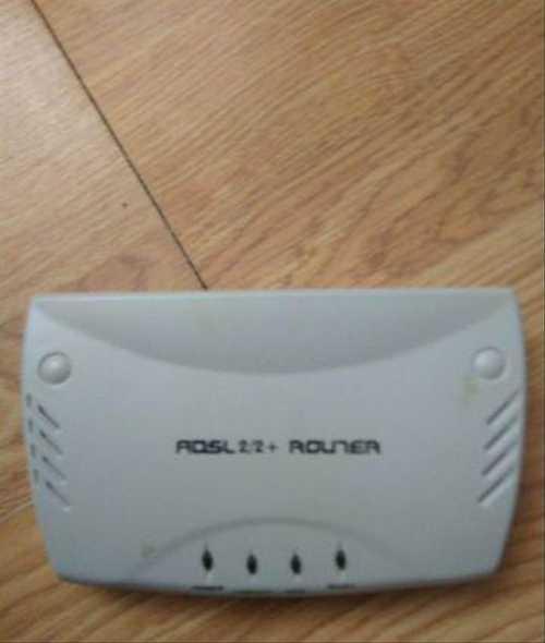
ADSL Модем X825 Annex B ADSL 2|2+ Router в новом состоянии и полном комплекте.
Мы нашли это объявление 5 лет назад
Нажмите Следить и система автоматически будет уведомлять Вас о новых предложениях со всех досок объявлений
| Вид электроники | Комьютерные аксессуары и комплектующие |
Адрес (Кликните по адресу для показа карты)
Санкт-Петербург, 2 линия, метро Озерки
Еще объявления
Продается абсолютно новый ADSL-модем (роутер) CJSC NEC X825 Port ADSL 2/2+. Полный комплект: роутер, блок питания, LAN-кабель, RJ-11 (2 шт.), ADSL-splitter, диск. Все запечатанное.
Комьютерные аксессуары и комплектующие

Модем в рабочем состоянии.
Комьютерные аксессуары и комплектующие

Внимание! Festima.Ru является поисковиком по объявлениям с популярных площадок.
Мы не производим реализацию товара, не храним изображения и персональные данные.
Все изображения принадлежат их авторам
Отказ от ответственности
adsl модем x825
Комьютерные аксессуары и комплектующие
Много лет лежал в коробке, не знаю, рабочий или нет. На фото всё, что к нему есть.
Комьютерные аксессуары и комплектующие

На чтение 10 мин Просмотров 9.2к.

Сергей Сакадынский
Работал в сфере IT-консалтинга, занимался созданием и администрированием интернет-ресурсов. 10 лет опыта работы по проектированию и обслуживанию компьютерных сетей.
Задать вопрос
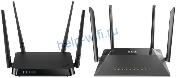
В этой статье мы будем разбираться с техническими параметрами и настройкой роутера D-Link DIR 825. Это двухдиапазонный гигабитный беспроводной маршрутизатор с USB-портом в среднем ценовом сегменте. Выпускается в нескольких модификациях, которые незначительно отличаются друг от друга.
Содержание
- Особенности версий и технические характеристики
- Подключение
- Вход в настройки роутера
- Автоматическая настройка
- Ручная настройка
- Подключение USB модема
- Подключение и параметры Wi-Fi
- Настройка IP TV
- Смена пароля
- Режим повторителя
- Обновление прошивки
- Сброс настроек
Особенности версий и технические характеристики
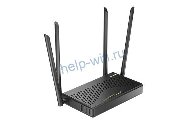
По характеристикам D-Link DIR 825 AC 1200 – современный роутер, рассчитанный на работу на частотах 2,4 и 5 ГГц. Скорость передачи данных достигает 300 и 867 Мбит/сек соответственно. Маршрутизатор оснащен четырьмя несъёмными антеннами с коэффициентом усиления 5 дБи. Режим MU-MIMO 2×2 позволяет работать одновременно с несколькими подключенными устройствами. Сетевые порты (4 LAN и 1 WAN) работают на скорости 1 Гбит/сек. Такой роутер позволит комфортно работать с любым провайдером, предоставляющим высокоскоростное подключение к интернету.
DIR 825 оснащён USB-портом 2.0 с поддержкой 3G/4G модемов, принтеров и носителей информации.
На передней панели размещены десять индикаторов, позволяющих отслеживать работу роутера.
- Питание – сообщает, что роутер включен.
- Интернет – показывает наличие или отсутствие соединения с провайдером.
- Четыре индикатора LAN-портов информируют о состоянии подключений по кабелю.
- Два индикатора Wi-Fi – 2,4G и 5G – показывают активность беспроводного подключения.
- WPS сообщает о работе одноименного режима.
- Индикатор USB показывает, что к порту подключено внешнее устройство.
Сзади расположены кнопки.
- POWER – кнопка включения и выключения питания.
- WI-FI – отключает и включает вещание беспроводной сети.
- Кнопка WPS – для установки беспарольного беспроводного соединения.
- RESET – отвечает за сброс настроек.
DIR 825 выпускается в нескольких версиях. В настоящее время в продаже доступны четыре.
DIR 825/R2 и DIR 825/R4 идентичны как внешне, так и в том, что касается внутренней начинки. За исключением встроенной флеш-памяти – у R4 её больше. Других отличий я не нашёл.

Модель DIR-825/L1отличается дизайном, отсутствием кнопки отключения Wi-Fi и индикатора WPS.
Все три модели оснащены процессором с частотой 1 ГГц и 128 мегабайтами оперативной памяти.
Модель DIR-825/GF (RU) оснащена процессором 900 мегагерц и 256 мегабайтами оперативки. Но главное отличие – оптический SFP-порт. Этот роутер предназначен для работы как с Ethernet, так и с оптоволоконными линиями.
Порты, их количество и скорость такие же, как и у остальных моделей.
Старые модели R1, E1A, 825ACG1, 825АС могут продаваться и использоваться, но с производства они уже сняты.
Подключение и настройка всех версий идентичны, поэтому инструкция по настройке роутеров D-Link DIR 825 будет общей.
Подключение
Здесь всё, как обычно. Чтобы подключить роутер D-Link DIR 825, выполняем следующие действия.
Кабель провайдера вставляем в порт WAN. Блок питания подсоединяем к разъёму на задней панели и включаем в сеть. Должны загореться индикаторы питания, Wi-Fi и интернет. Если роутер не подаёт признаков жизни, проверьте, в каком положении находится кнопка POWER.

Для подключения к роутеру по кабелю соедините сетевую карту своего ПК с любым портом LAN патч-кордом, который прилагается в комплекте к роутеру. Для сетевой карты должен быть установлен параметр «Получать IP-адрес автоматически».

Если вы будете настраивать роутер по Wi-Fi, подключитесь к одной из сетей DIR-825 или DIR-825-5G. Ключ доступа указан на наклейке на нижней панели маршрутизатора.
Вход в настройки роутера
Запустите любой браузер на вашем компьютере, введите в адресной строке IP 192.168.0.1 и нажмите клавишу Enter. Если вы настраиваете DIR 825 в первый раз, появится окно с предложением запустить автоматическую настройку.

Нажмите кнопку «Начать».
Автоматическая настройка
Мастер настройки сразу же предложит установить пароль для доступа в веб-интерфейс, имя беспроводной сети и ключ доступа к ней.

После того, как вы это сделаете, запустится автоматическая установка. Если этого не произошло, в меню слева откройте «Начало» и нажмите Click’n Connect. Так это выглядит в AIR-интерфейсе.

В старом интерфейсе всё точно так же.

Вам будет предложено подключить Ethernet-кабель к WAN-порту. Вероятно, вы это уже сделали. Если не сделали, то самое время устранить эту недоработку.

Дальше я буду показывать этапы быстрой настройки на примере нового интерфейса. В старом всё работает точнго так же, только в другом дизайне.
На следующем шаге нужно выбрать провайдера из списка или указать пункт «Вручную».

Затем выбираем тип подключения из списка.

Большинство провайдеров используют динамический IP. С ним всё просто. Нужно подтвердить выбор, и интернет подключится сразу. Для изменения дополнительных параметров нажмите «Подробно» внизу страницы.

Здесь нас интересует параметр «МАС-адрес». Возможно, его придётся клонировать с компьютера или ввести вручную. Всё зависит от требований вашего провайдера.

Если же у вас какой-то другой тип подключения, выберите его и укажите нужные параметры. Понадобятся имя пользователя, пароль, возможно, адрес сервера или IP-адрес. Вся информация предоставляется вашим провайдером.

После того, как указана вся информация, жмите «Далее», проверьте настройки и кликните по кнопке «Применить». Появится сообщение о том, что подключение установлено. Можно переходить к следующему шагу.
Мастер настройки предложит включить Яндекс.DNS.

Тут можно ничего не менять. Жмите кнопку «Далее». Выберите режим работы. Вариантов всего два. В вашем случае это, конечно же, точка доступа.

Поочерёдно настройте вашу сеть в режиме 2,4 и 5 ГГц. Сохраните настройки.

Далее будет предложено настроить IPTV. Этот шаг можно пропустить. В последнем окне нажмите кнопку «Применить». На этом базовая настройка DIR 825 завершена.
Ручная настройка
Если нужно выполнить настройку роутера вручную, снова войдите в веб-интерфейс, используя пароль, который вы придумали в самом начале. В AIR-интерфейсе вы сразу попадёте в меню. В старой прошивке внизу экрана жмите кнопку «Расширенные настройки».

Для изменения параметров интернет-соединения открываем меню «Сеть» — WAN.


Для добавления подключения жмите кнопку «Добавить» и укажите тип подключения и другие данные.

Сведения, необходимые для настройки PPPoE, PPPTP или L2TP соединения, уточняйте у вашего провайдера.
Подключение USB модема
Для настройки подключения к интернету через мобильную сеть на вкладке WAN выберите тип подключения 3G и провайдера из списка.

Данные здесь подставляются автоматически с СИМ-карты. Если же по каким-то причинам этого не произошло, уточните их у оператора.
Если ваша карта защищена PIN-кодом, внизу страницы вы увидите вот такое сообщение:

Кликните по ссылке «ввести PIN (или PUK) код» и укажите ключ разблокировки. После завершения настройки нажмите кнопку «Применить».
Подключение и параметры Wi-Fi
Чтобы настроить Wi-Fi на D-Link DIR 825, перейдите в пункт меню Wi-Fi – «Основные настройки» и выберите диапазон вещания, который будете настраивать.

Тип шифрования и ключ сети устанавливается в пункте «Настройка безопасности».

Параметры задаются для каждой сети отдельно.
МАС-фильтр позволяет заблокировать или, наоборот, разрешить доступ к вашей сети определённым устройствам. В разделе «Список Wi-Fi клиентов» отображаются подключенные в данный момент пользователи. В разделе WPS можно отключить или включить эту функцию для каждого диапазона.
Настройка IP TV
Если вы пропустили этот шаг на этапе быстрой настройки, при необходимости можно задать нужные параметры вручную. В основном, всё сводится к назначению функций порту Ethernet.
В старой версии прошивки на главном экране есть пункт IP-телевидение – Мастер настройки IPTV.

В интерфейсе AIR откройте пункт меню «Начало» — «Мастер настройки IPTV».

Здесь нужно выбрать из четырёх портов LAN тот, который будет использоваться для подключения ТВ-приставки.

В большинстве случаев, больше ничего делать не нужно.
Если же ваш провайдер требует указать дополнительные параметры для IPTV, сделать это можно в пункте меню «Дополнительно» — VLAN. Сначала выбираем существующий порт и удаляем его, нажав кнопку «Удалить» внизу. Затем жмём кнопку «Добавить» и выполняем настройку.

Идентификатор VLAN и другие данные нужно узнать у провайдера.
Смена пароля
Пароль доступа в веб-интерфейс из соображений безопасности рекомендуется менять регулярно. При этом желательно использовать сложные пароли, состоящие из букв в разном регистре, цифр и символов.
Сделать это можно в меню «Система» — «Пароль администратора».

Выполняется эта операция просто: дважды введите новый пароль и нажмите кнопку «Применить».
Режим повторителя
Для расширения зоны действия беспроводной сети на DIR 825 предусмотрен режим повторителя или усилителя. Этот режим называется «Клиент».
Для подключения к другой сети и ретрансляции её сигнала откройте меню Wi-Fi — «Клиент».

Поставьте галочку «Включить» и «Вещать» в одном или обоих диапазонах. Нажмите кнопку «поиск сетей» на нужной частоте. Отобразится список доступных сетей. Выберите нужную, кликните по ней и введите ключ доступа. Сохраните изменения.
Роутер подключится к Wi-Fi сети другого маршрутизатора и будет её ретранслировать.
Обновление прошивки
Вариантов обновления программного обеспечения два – автоматический и ручной. По умолчанию роутер проверяет наличие новой версии и сообщает об этом пользователю.
Для обновления в автоматическом режиме перейдите в раздел «Система» – «Обновление ПО».

Здесь нажмите кнопку «Проверить обновления». Если доступна новая прошивка, появится сообщение с предложением запустить обновление. Жмите ОК и ждите завершения процесса.
При этом роутер нельзя выключать и отключать от интернета.
Бывает, что по какой-то причине автоматическое обновление невозможно. Тогда прошивку для D-Link DIR 825 нужно скачать с сайта производителя и выполнить обновление вручную.
Найдите на сайте вашу модель устройства. Важно, чтобы она полностью совпадала. Выберите из списка нужную версию и скачайте на ваш компьютер.

После этого войдите в веб-интерфейс роутера и откройте «Система» — «Обновление ПО». В верхней части окна в разделе «Локальное обновление» через кнопку «Обзор» укажите путь к файлу прошивки и нажмите кнопку «Обновить».
Сброс настроек
Сбросить настройки роутера D-Link DIR 825 AC к заводским может потребоваться, если в его работе начались сбои, устройство часто зависает, обрывается подключение или вы что-то изменили в параметрах, после чего интернет пропал. Сбросить настройки можно двумя способами
Первый через веб-интерфейс устройства. Идём в пункт меню «Система» — «Конфигурация». Здесь, кстати, можно сделать резервную копию ваших параметров, чтобы можно было быстро восстановить работоспособность роутера. Но делать это нужно заранее. Когда начались проблемы, поможет только сброс.

Нажимаем кнопку «Заводские настройки», подтверждаем выбор и ждём завершения процесса. Роутер перезагрузится. Теперь его придётся настраивать с нуля.
Второй способ аппаратный. Им придётся воспользоваться, если вы забыли и хотите сбросить пароль на роутере D-Link DIR 825.
На задней панели роутера есть кнопка RESET. Её нужно зажать и удерживать около десяти секунд. Питание роутера должно быть включено. Индикаторы на передней панели мигнут и начнётся перезагрузка. Устройство запустится с заводскими настройками.
-

-
September 1 2007, 02:41
Вопрос по модему
Сегодня оформил Авангард. Выдали какой-то noname LAN-модем
По документам называется XAVI, но на нем это не написано. Модель X825. Написано CJSC NEC NEVA COMMUNICATION SYSTEM. 1 Port ADSL 2/ 2+ Router. Даже написано, что драйверов не требуется…
Нормальный? Лучше, чем USB Dlink DSL-200 будет? Этот все же LAN…
Очень многие провайдеры на сегодняшний день работают по технологии ADSL. Поэтому для осуществления подключения к оборудованию такого типа необходимо наличие специальных устройств – ADSL-модемов. Единственное неудобство такого соединения заключается в том, что подключать к данному модему обычно можно только один ПК, через многожильный кабель связи.
Выходом из сложившейся ситуации может стать приобретение Wi-Fi-роутера, способного работать в связке с модемом такого типа. Также существуют модели роутеров, который совмещают в себе маршрутизатор и ADSL-модем.
При выборе роутера необходимо точно знать, что он поддерживает совместную работу с модемом АДСЛ. Проще всего настроить совместную работу модема такого типа и роутера D-Link DIR 320.

Когда осуществляется настройка ADSL-модема в режиме роутера, необходимо должным образом настроить сам модем. Он также должен «уметь» кооперироваться с оборудованием Wi-Fi.

Один из самых простых в настройке модемов такого типа – ZyXelP-660RT2 .
Видео: Установка и настройка Wi-Fi роутера
Подготовка модема
Для успешной настройки связки ADSL-модем – Wi-Fi-роутер необходимо правильно подготовить к работе сам модем. Рассматриваемая модель должна быть переведена в режим «мост». В настройках этот режим называется «Bridge». Данный режим позволяет модему устанавливать соединение с провайдером – поставщиком услуг интернет – и после этого как бы самоудаляться, просто пропуская весь трафик через себя. Фактически, устройство будет выступать в качестве переходника между всемирной сетью и роутером. Настройка выполняется следующим образом:
- в адресной строке любого браузера на ПК вводится комбинация цифр – 192.168.1.1

;
- в открывшемся окне будет необходимо ввести пароль 1234 (он установлен по умолчанию);
- в следующем окне необходимо выбрать тип внешнего вида страницы настройки. Следует установить галочку напротив «gotoadvancedsetup»;
- далее необходимо посетить меню Network->WAN. При нажатии на закладку «InternetConnection» можно увидеть поле под названием «Mode». Следует установить там режим «Bridge» (мост);
- обязательно нужно уделить внимание полю «Encapsulation», перевести модем в режим RFC 1483;
- в поле «VPI/VCI» и «Multiplex» значения различаются в зависимости от оператора.


После окончания настройки самого модема настраивается сам ПК. Так как в режиме моста модем устанавливает соединение лишь физически. Для авторизации пользователя необходимо создать отдельное соединение на компьютере, к которому он подключен.
Подготовка ПК
Настройка модема окончена, необходимо подключить его к компьютеру под управлением какой-либо версии операционной системы Windows. Так как настройка работы в этой среде максимально проста. Когда физически ADSL-модем к компьютеру подключен, необходимо выполнить следующие действия:
- установить драйвера для модема (если это требуется);
- создать PPPoE соединение.
Создание соединения данного типа осуществляется следующим образом:
- необходимо зайти в «Панель управления»-> «Управление сетевыми подключениями». В открывшемся окне находим значок под названием «Установка подключения или сети»;
- после этого операционной системой будет запущен «мастер подключения к интернету». Откроется окно, в котором необходимо будет выбрать «Все равно создать новое подключение»;
- откроется следующее окно, в нем операционная система предложит два варианта: «нет, создать новое подключение» и «Да, выбрать существующее подключение». Следует поставить галочку на первом пункте;
- в новом окне также будут присутствовать два пункта: «Высокоскоростное подключение PPPoE», «Коммутируемое». Останавливаемся на втором пункте;
- в следующем окне необходимо ввести логин и пароль для подключения. Эти данные должны быть предоставлены провайдером;
- далее операционная система оповестит о том, что подключение проверить не удалось. На выбор будут три пункта: «повторить попытку», «установить причину», «все равно создать это подключение». Следует выбрать последний, после чего можно смело закрывать мастер настройки подключений.


Когда настройка уже выполнена, можно подключать Wi-Fi-роутер и начинать работу.
Существуют роутеры, которые могут работать с подключением ADSL напрямую, без посредника в виде специального модема. Конечно же, цена такого устройства на порядок выше, чем обычного роутера. Например, Zyxel Keenetic DSL обойдется пользователю в 2400 руб.

Для подключения понадобятся некоторые данные, которые должны предоставляться провайдером:
- IP-адрес, если он является статическим;
- логин и пароль для подключения к линии;
- тип инкапсуляции (LLC или VC);
- данные по VPI.
Подключение компьютера и роутера Keenetic DSL к сети может быть выполнено как в автоматическом режиме, при помощи специальной программы, так и в ручном режиме. Если возможность автоматической настройки исключена, то настройка в ручном режиме выполняется следующим образом:
- необходимо подключиться к WEB-конфигуратору. В окне следует найти меню «интернет»->ADSL и кликнуть мышью по ADSL;
- после выполнения предыдущего пункта откроется окно, в котором необходимо будет ввести все данные по подключению в ручном режиме.
Сделать это необходимо в соответствии с требованиями провайдера. Когда все необходимые параметры введены, можно нажать кнопку «Сохранить»;
- в разделе «интернет» следует выполнить настройку раздела «PPPoE/VPN». Необходимо нажать кнопку «Добавить соединение». После этого установить галочки в пунктах «Включить», «Использовать для выхода в интернет». В разделе «Тип» выбирается «PPPoE». «Подключаться через»-> «ADSL-соединение»;
- вводится имя пользователя и пароль. Если IP-адрес провайдером присваивается статический – необходимо указать его в графе «Настройка параметров IP», в противном случае выбрать автоматический режим.


На данном этапе настройка ADSL-роутера завершается.
Как настроить роутер через ADSL-модем
Когда необходимо настроить работу роутера через ADSL-модем, реализуется схема следующего вида:
- настройка модема заключается лишь в его подключении к интернету и переходе в режим «Мост». После этого выполняются действия, позволяющие сделать сеть доступной через интерфейс Wi-Fi (для роутера P-330W):
- используется WEB-конфигуратор для установки режима «Gateway». В пункте под названием «WAN AccessType» установить значение PPPoE;
- используется WEB-конфигуратор для установки режима «Gateway». В пункте под названием «WAN AccessType» установить значение PPPoE;
- после выполнения пункта первого достаточно просто указать имя пользователя и пароль, которые предоставляет провайдер для подключения к интернету;


Режимы работы ADS- модема
ADSL-модемы могут работать всего в двух режимах:
- режим роутера;
- режим моста.
Настройка ADSL модема в режиме роутера заключается в изменении режима через WEB-интерфейс. Данный режим превращает устройство связи в самостоятельный маленький сервер. Его работа включает в себя хранение данных об авторизации, различные параметры, необходимые при соединении.
Также в данном режиме модем самостоятельно поддерживает соединение, а при обрыве связи без посторонней помощи переподключается. Особенностью данного режима является то, что в модеме имеется функция фаервола.
Когда модем переключен в режим моста, он представляет собой просто промежуточное устройство между самой сетью и сетевой картой персонального компьютера. Параметры соединения и данные авторизованных пользователей хранятся на самом ПК.
Видео: настройка параметров ADSL модема
Настройка Wi-Fi
Настройка Wi-Fi большинства роутеров ограничивается постановкой галочки напротив «Enabled» или «Disabled». Также необходимо как-либо назвать сеть, созданную роутером и выбрать режим защиты (обычно это WPA2).

Настройка ADSL модема и роутера, а также оборудования, совмещающего в себе функции этих устройств – процесс довольно простой. Важно лишь внимательно изучить спецификацию аппаратов и способы их подключения.
Wi-Fi сегодня является одной из самых часто используемых технологий, применяемых для выхода в интернет. Но многие операторы работают с ADSL-технологией, а стоимость интернет-центра (совмещающего в себе роутер и ADSL-модем) довольно велика. Поэтому тема настройки и использования связки ADSL-модем->ПК-> Wi-Fi-роутер чрезвычайно актуальна.