По языку
По категории продукции
Введите название модели или ключевые слова
Yamaha RX-V357 Owner’s manual
Бренд:
Yamaha
Категория:
AV receivers
Размер:
805 KB
Страниц:
59
Язык(и):
Чешский, Датский, Немецкий, Английский, Испанский, Финский, Французский, Венгерский, Индонезийский, Итальянский, Корейский, Голландский, no, Польский, Португальский, Румынский, Русский, Шведский, Турецкий, Вьетнамский, zh
Открыть в новой вкладке
Страница скачивания руководства по обслуживанию Yamaha RX-V357
Размер: 0,83 MB
Добавлено: 2013-02-21 15:17:03
Количество страниц: 59
Скачивание руководства по обслуживанию Yamaha RX-V357 должно начаться в течении нескольких секунд. Если загрузка не началась автоматически в течение 10 секунд, нажмите на Прямая ссылка. Если у Вас остаются проблемы со скачиванием инструкции Yamaha RX-V357, свяжитесь с нами, используя формуляр для сообщения об ошибках.;
Rx-v357, High sound quality, Surround realism

Powerful 525W (105W x 5 DIN) 5.1-Channel Surround Sound with
Quad-Field CINEMA DSP and Many Other Exclusive Yamaha
Features for a Thoroughly Enjoyable Home Cinema Experience.
5.1-Channel Digital Home Cinema Receiver
is also available
P R O L O G I C
High Sound Quality
192kHz/24-bit D/A Converters for All Channels
5.1-Channel, 525W Powerful Surround Sound (105W x 5 DIN)
Night Listening Mode and SILENT CINEMA
Dolby Digital/Matrix 6.1 and DTS/Matrix 6.1 Compatibility
plus Dolby Pro Logic II Decoding
Quad-Field and Tri-Field CINEMA DSP and
14 Surround Programmes
5-Band Centre Graphic Equalizer
2 Component Video Inputs and 3 Digital inputs

- Языки: Русский
- Тип: PDF
- Размер: 1.17 MB
- Описание: Ресивер
На NoDevice можно скачать инструкцию по эксплуатации для Yamaha RX-V359. Руководство пользователя необходимо для ознакомления с правилами установки и эксплуатации Yamaha RX-V359. Инструкции по использованию помогут правильно настроить Yamaha RX-V359, исправить ошибки и выявить неполадки.

YAMAHA ELECTRONICS CORPORATION, USA 6660 ORANGETHORPE AVE., BUENA PARK, CALIF. 90620, U.S.A.
YAMAHA CANADA MUSIC LTD. 135 MILNER AVE., SCARBOROUGH, ONTARIO M1S 3R1, CANADA
YAMAHA ELECTRONIK EUROPA G.m.b.H. SIEMENSSTR. 22-34, 25462 RELLINGEN BEI HAMBURG, GERMANY
YAMAHA ELECTRONIQUE FRANCE S.A. RUE AMBROISE CROIZAT BP70 CROISSY-BEAUBOURG 77312 MARNE-LA-VALLEE CEDEX02, FRANCE
YAMAHA ELECTRONICS (UK) LTD. YAMAHA HOUSE, 200 RICKMANSWORTH ROAD WATFORD, HERTS WD18 7GQ, ENGLAND
YAMAHA SCANDINAVIA A.B. J A WETTERGRENS GATA 1, BOX 30053, 400 43 VÄSTRA FRÖLUNDA, SWEDEN
YAMAHA MUSIC AUSTRALIA PTY, LTD. 17-33 MARKET ST., SOUTH MELBOURNE, 3205 VIC., AUSTRALIA
Printed in China
WE59660
©2005 All rights reserved.
OWNER’S MANUAL
MODE D’EMPLOI
BEDIENUNGSANLEITUNG
BRUKSANVISNING
GEBRUIKSAANWIJZING
ИНСТРУКЦИЯ ПО ЭКСПЛУАТАЦИИ
RX-V357
G
AV Receiver
Ampli-tuner audio-vidéo
R X-V357

1To assure the finest performance, please read this
manual carefully. Keep it in a safe place for future
reference.
2 Install this sound system in a well ventilated, cool,
dry, clean place – away from direct sunlight, heat
sources, vibration, dust, moisture, and/or cold.
Allow ventilation space of at least 30 cm on the top,
20 cm on the left and right, and 20 cm on the back
of this unit.
3 Locate this unit away from other electrical
appliances, motors, or transformers to avoid
humming sounds.
4
Do not expose this unit to sudden temperature
changes from cold to hot, and do not locate this unit
in a environment with high humidity (i.e. a room with
a humidifier) to prevent condensation inside this unit,
which may cause an electrical shock, fire, damage to
this unit, and/or personal injury.
5Avoid installing this unit where foreign object may
fall onto this unit and/or this unit may be exposed
to liquid dripping or splashing. On the top of this
unit, do not place:
– Other components, as they may cause damage
and/or discoloration on the surface of this unit.
–
Burning objects (i.e. candles), as they may cause
fire, damage to this unit, and/or personal injury.
– Containers with liquid in them, as they may fall
and liquid may cause electrical shock to the
user and/or damage to this unit.
6 Do not cover this unit with a newspaper, tablecloth,
curtain, etc. in order not to obstruct heat radiation.
If the temperature inside this unit rises, it may
cause fire, damage to this unit, and/or personal
injury.
7 Do not plug in this unit to a wall outlet until all
connections are complete.
8 Do not operate this unit upside-down. It may
overheat, possibly causing damage.
9 Do not use force on switches, knobs and/or cords.
10 When disconnecting the power cord from the wall
outlet, grasp the plug; do not pull the cord.
11 Do not clean this unit with chemical solvents; this
might damage the finish. Use a clean, dry cloth.
12 Only voltage specified on this unit must be used.
Using this unit with a higher voltage than specified
is dangerous and may cause fire, damage to this
unit, and/or personal injury. YAMAHA will not be
held responsible for any damage resulting from use
of this unit with a voltage other than specified.
13
To prevent damage by lightning, disconnect the power
cord from the wall outlet during an electrical storm.
14 Do not attempt to modify or fix this unit. Contact
qualified YAMAHA service personnel when any
service is needed. The cabinet should never be
opened for any reasons.
CAUTION: READ THIS BEFORE OPERATING YOUR UNIT.
15 When not planning to use this unit for long periods
of time (i.e. vacation), disconnect the AC power
plug from the wall outlet.
16 Be sure to read the “TROUBLESHOOTING” section
on common operating errors before concluding that
this unit is faulty.
17 Before moving this unit, press STANDBY/ON to set
this unit in standby mode, and disconnect the AC
power plug from the wall outlet.
This unit is not disconnected from the AC power
source as long as it is connected to the wall outlet,
even if this unit itself is turned off. This state is called
standby mode. In this state, this unit is designed to
consume a very small quantity of power.
WARNING
TO REDUCE THE RISK OF FIRE OR ELECTRIC
SHOCK, DO NOT EXPOSE THIS UNIT TO RAIN
OR MOISTURE.

1
INTRODUCTION
PREPARATION
BASIC
OPERATION
ADVANCED
OPERATION
ADDITIONAL
INFORMATION
English
CONTENTS
INTRODUCTION
FEATURES…………………………………………………….2
GETTING STARTED……………………………………..3
Supplied accessories…………………………………………..3
Installing batteries in the remote control ……………….3
CONTROLS AND FUNCTIONS ……………………. 4
Front panel ……………………………………………………….4
Remote control ………………………………………………….6
Front panel display …………………………………………….8
PREPARATION
CONNECTIONS …………………………………………….9
Before connecting components ……………………………9
Connecting video components …………………………..10
Connecting audio components …………………………..12
Connecting the antennas …………………………………..13
Connecting an external decoder …………………………14
Connecting the speakers ……………………………………15
Connecting the power supply cord……………………..18
Turning on the power ……………………………………….18
BASIC SYSTEM SETTINGS ………………………..19
Using the basic menu ……………………………………….19
Setting the unit to match your speaker system ……..21
SP LEVEL (Setting speaker output levels) ………….21
BASIC OPERATION
PLAYBACK ………………………………………………….22
Input modes and indications………………………………24
Selecting a sound field program …………………………25
DIGITAL SOUND FIELD PROCESSING
(DSP) ……………………………………………………….. 28
Understanding sound fields ……………………………….28
HiFi DSP programs ………………………………………….28
CINEMA DSP ……………………………………………….29
Sound design of CINEMA DSP …………………………29
CINEMA DSP Programs …………………………………..29
Sound field effects ……………………………………………31
TUNING……………………………………………………….32
Presetting stations…………………………………………….33
Selecting preset stations ……………………………………35
RECEIVING RADIO DATA SYSTEM …………. 36
Description of Radio Data System data ………………36
Changing the Radio Data System mode………………36
PTY SEEK function …………………………………………37
EON function ………………………………………………….37
SLEEP TIMER …………………………………………….. 38
RECORDING ……………………………………………….39
ADVANCED OPERATION
SET MENU …………………………………………………..40
Set menu list ……………………………………………………40
Adjusting the items on the set menu ………………….. 40
SOUND 1 SPEAKER SET
(speaker mode settings)…………………………………41
SOUND 2 SP DISTANCE (speaker distance) …….. 43
SOUND 3 LFE LEVEL ……………………………………43
SOUND 4 D. RANGE (dynamic range) ……………..43
SOUND 5 CENTER GEQ
(center graphic equalizer) ……………………………..44
SOUND 6 HP TONE CTRL
(headphone tone control) ……………………………… 44
INPUT 1 I/O ASSIGN
(input/output assignment) ……………………………..44
INPUT 2 INPUT MODE (initial input mode)………44
OPTION 1 DISPLAY SET ………………………………..45
OPTION 2 MEM. GUARD (memory guard) ………45
OPTION 3 AUDIO MUTE ……………………………….45
ADVANCED SETUP MENU ………………………… 46
SETTING THE SPEAKER LEVELS…………….47
Adjusting the speaker levels during playback………47
Using the test tone ……………………………………………47
ADDITIONAL INFORMATION
EDITING SOUND FIELD PARAMETERS ….. 48
Changing parameter settings ……………………………..48
Sound field parameter descriptions …………………….49
TROUBLESHOOTING ………………………………..50
RESETTING THE FACTORY PRESETS ……..53
GLOSSARY ………………………………………………….54
SPECIFICATIONS ……………………………………….56

2
Manufactured under license from Dolby Laboratories.
“Dolby”, “Pro Logic”, and the double-D symbol are
trademarks of Dolby Laboratories.
“SILENT CINEMA” is a trademark of YAMAHA
CORPORATION.
FEATURES
“DTS” and “DTS Digital Surround” are registered
trademarks of Digital Theater Systems, Inc.
Built-in 5-channel power amplifier
◆ Minimum RMS output power
(0.9% THD, 1 kHz, 6 Ω)
Front: 100 W + 100 W
Center: 100 W
Surround: 100 W + 100 W
Sound field features
◆ Dolby Pro Logic/Dolby Pro Logic II decoder
◆ Dolby Digital/Dolby Digital + Matrix 6.1 Decoder
◆ DTS/DTS + Matrix 6.1 Decoder
◆ CINEMA DSP: Combination of YAMAHA DSP
technology and Dolby Pro Logic, Dolby Digital or
DTS
◆ Virtual CINEMA DSP
◆ SILENT CINEMA ™
Sophisticated AM/FM Tuner
◆ 40-Station random access preset tuning
◆ Automatic preset tuning
◆ Preset station shifting capability (Preset editing)
■ About this manual
• y indicates a tip for your operation.
• Some operations can be performed by using either the buttons on the main unit or on the remote control. In cases
when the button names differ between the main unit and the remote control, the button name on the remote control is
given in parentheses.
•This manual is printed prior to production. Design and specifications are subject to change in part for the reason of
the improvement in operativity ability, and others. In this case, the product has priority.
Other features
◆ 192 kHz/24-bit D/A converter
◆ Set menu for optimizing this unit for your Audio/
Video system
◆ Test tone generator for easier speaker balance
adjustment
◆ 6-channel external decoder input
◆ Optical and coaxial digital audio signal jacks
◆ Sleep timer
3
INTRODUCTION
English
1
2
4
3
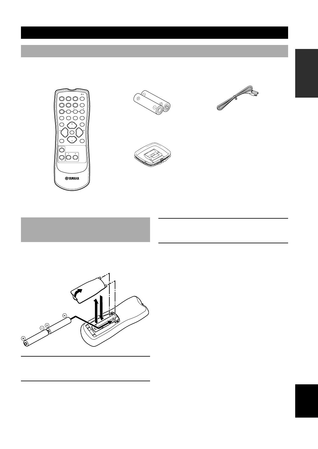
AM loop antenna
Indoor FM antenna
Batteries (2)
(AA, R06, UM-3)
Remote control
GETTING STARTED
Supplied accessories
Please check that you received all of the following parts.
Installing batteries in the remote
control
Insert the batteries in the correct direction by aligning the
+ and – marks on the batteries with the polarity markings
(+ and –) inside the battery compartment.
1 Press the tab of the battery compartment
cover and pull it in the direction of the arrow
to open the cover.
2 Remove the cover.
TEST
PROG PROG
STEREO
LEVEL
SET MENU
TUNER
CD MD/CD-R V-AUX 6CH IN
q
/DTS 6.1/5.1
NIGHT SLEEP
DVD D-TV/CBL VCR
PRESETA/B/C/D/E
MUTE
VOLUME
VOLUME
POWER
3 Insert the two batteries supplied (AA, R06,
UM-3) according to the polarity markings on
the inside of the battery compartment.
4 Put the cover back into place.
■ Notes on batteries
• Change all of the batteries if you notice a decrease in
the operating range of the remote control.
• Do not use old batteries together with new ones.
• Do not use different types of batteries (such as alkaline
and manganese batteries) together. Read the packaging
carefully as these different types of batteries may have
the same shape and color.
• If the batteries have leaked, dispose of them
immediately. Avoid touching the leaked material or
letting it come into contact with clothing, etc. Clean the
battery compartment thoroughly before installing new
batteries.
• Do not throw away batteries with general house waste;
dispose of them correctly in accordance with your local
regulations.
4
VOLUME
AUTO/MAN’L MONOMAN’L/AUTO FMSET MENUNEXTEDIT
EFFECT
MEMORY
FM/AM
PRESET/TUNING
A/B/C/D/E
l PROGRAM h
BASS/TREBLE
l
PRESET/TUNING
h
TUNING MODE
INPUT MODE
TONE CONTROL
STEREO
SPEAKERS
A/B/OFF
PHONES
SILENT CINEMA
STANDBY
/ON
6CH INPUT
l INPUT h
21347 856 9
ouyrwqeti
0
FREQ/TEXT EON
MODE
PTY SEEK
START
asdp
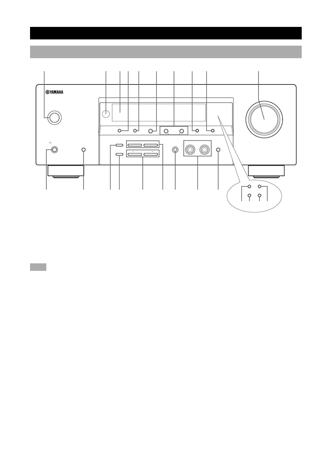
CONTROLS AND FUNCTIONS
Front panel
1 STANDBY/ON
Turns on this unit or sets it to the standby mode. When
you turn on this unit, you will hear a click and there will
be a 4 to 5-second delay before this unit can reproduce
sound.
Note
• In standby mode, this unit consumes a small amount of power
in order to receive infrared-signals from the remote control.
2 Remote control sensor
Receives signals from the remote control.
3 Front panel display
Shows information about the operational status of the
unit.
4 PRESET/TUNING
Switches the function of PRESET/TUNING l / h
between selecting a preset station number and tuning (the
colon (:) turns on or off).
(EDIT)
This button is also used to exchange the assignment of
two preset stations with each other.
5 FM/AM
Switches the reception band between FM and AM.
6 A/B/C/D/E
Selects preset station groups A to E when the unit is in
tuner mode.
(NEXT)
Selects the set menu mode when the unit is not in tuner
mode.
7 PRESET/TUNING l / h
Select preset station numbers 1 to 8 when a colon (:) is
displayed in the front panel display.
Select the tuning frequency when a colon (:) is not
displayed in tuner mode.
(SET MENU –/+)
Adjust settings on the set menu when the unit is not in
tuner mode.
8 MEMORY (MAN’L/AUTO FM)
Stores a station in the memory.
9 TUNING MODE (AUTO/MAN’L MONO)
Switches the tuning mode between automatic and manual.

5
INTRODUCTION
English
0 VOLUME
Controls the output level of all audio channels.
This does not affect the OUT (REC) level.
q
PHONES (SILENT CINEMA)
Allows you to enjoy DSP effects when listening with
headphones.
w SPEAKERS A/B/OFF
Selects the set of front speakers connected to the A or B
terminals. To turn off the speakers, press the button
repeatedly and select OFF.
e STEREO (EFFECT)
Switches between normal stereo and DSP effect
reproduction. When you select STEREO, the unit mixes
down all Dolby Digital and DTS signals (except the LFE
channel) as well as those 2-channel signals without effect
sounds to the front left and right speakers.
r TONE CONTROL
Switches between Bass (low-frequency response) control
mode and Treble (high-frequency response) control mode.
t BASS/TREBLE –/+
Increase or decrease low/high-frequency response when
the unit is in Bass/Treble control mode. The sound
changes 2dB each time you press one of these buttons.
Control range: –10 to +10 dB
y PROGRAM l / h
Use to select sound field programs.
u INPUT MODE
Sets the priority for the types of input signals (AUTO,
DTS, ANALOG) received when one component is
connected to two types of input jacks. You cannot set
priority for an audio sources if you have selected 6CH
INPUT as the input source.
i INPUT l / h
Selects the input source you want to listen to or watch.
o 6CH INPUT
Selects the audio source connected to the 6CH INPUT
jacks. This selection takes priority over sources selected
with INPUT (or the input selector buttons on the remote
control).
CONTROLS AND FUNCTIONS
p FREQ/TEXT
Press this button when the unit is receiving an Radio Data
System station, to cycle the display mode among PS
mode, PTY mode, RT mode, CT mode (if the station
offers those Radio Data System data service) and/or
frequency display mode in turn.
a PTY SEEK MODE
Press this button to set the unit in the PTY SEEK mode.
s PTY SEEK START
Press this button to begin searching for a station after the
desired program type has been selected in the PTY SEEK
mode.
d EON
Press this button to select a radio program type (NEWS,
INFO, AFFAIRS, SPORT) to tune in automatically.
6
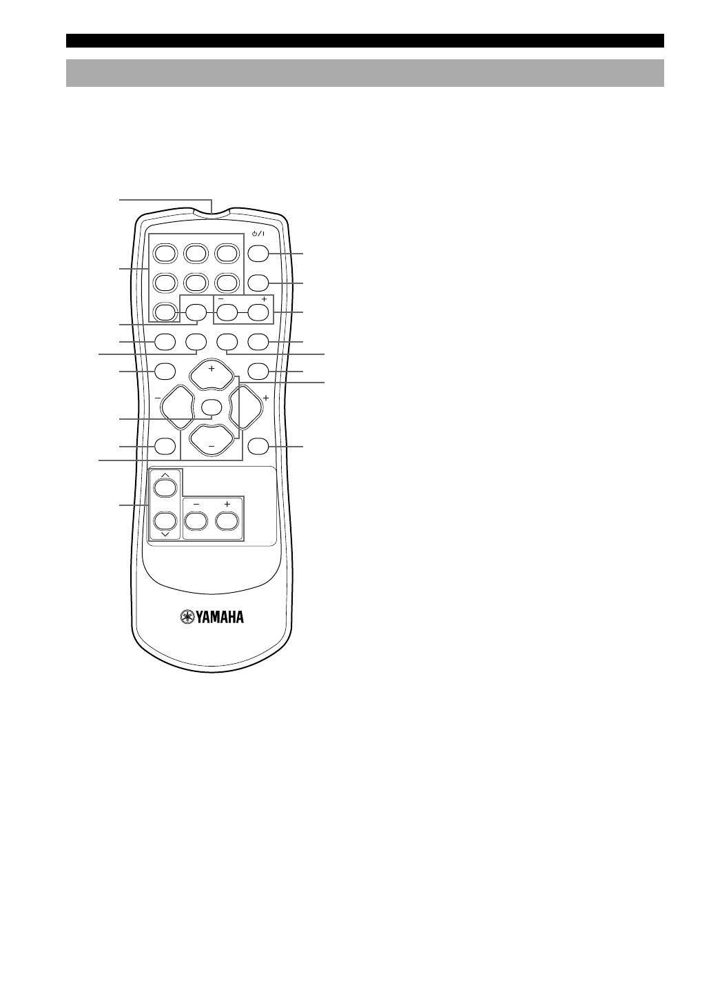
Remote control
1 Infrared emitter
Outputs infrared control signals. Aim this emitter at the
component you want to operate.
2 Input selector buttons
Select the input source.
3 A/B/C/D/E
Selects preset station groups A to E when the unit is in
tuner mode.
4 q/DTS
Selects the built-in Dolby Digital, DTS, Dolby Pro Logic,
or Pro Logic II decoder.
5 6.1/5.1
Switches on or off the Dolby Digital + Matrix 6.1 or
DTS + Matrix 6.1 decoder.
6 TEST
Outputs the test tone to adjust the speaker levels.
7 MUTE
Mutes the sound. Press again to restore the audio output
to the previous volume level.
8 LEVEL
Selects the effect speaker channel to adjust.
9 PROG –/+
Use to select sound filed programs.
0 Multi control section
Use to select and adjust sound field program parameters
or SET MENU items.
q POWER
Turns the unit on, or sets it in standby mode.
w 6CH IN
Selects the audio source connected to the 6CH IN jacks.
e PRESET –/+
Select preset station numbers 1 to 8.
CONTROLS AND FUNCTIONS
This section describes the controls and functions of the
remote control.
TEST
PROG PROG
STEREO
LEVEL
SET MENU
TUNER
CD MD/CD-R V-AUX 6CH IN
q
/DTS 6.1/5.1
NIGHT SLEEP
DVD D-TV/CBL VCR
PRESETA/B/C/D/E
MUTE
VOLUME
VOLUME
POWER
q
w
e
y
i
r
t
1
2
4
6
5
3
9
8
0
u
7
7
INTRODUCTION
English
VOLUME
FREQ/TEXT EON
MODE
PTY SEEK
START
AUTO/MAN’L MONOMAN’L/AUTO FMSET MENUNEXTEDIT
EFFECT
MEMORY
FM/AM
PRESET/TUNING
A/B/C/D/E
l PROGRAM h
BASS/TREBLE
l
PRESET/TUNING
h
TUNING MODE
INPUT MODE
TONE CONTROL
STEREO
SPEAKERS
A/B/OFF
PHONES
SILENT CINEMA
STANDBY
/ON
6CH INPUT
l INPUT h
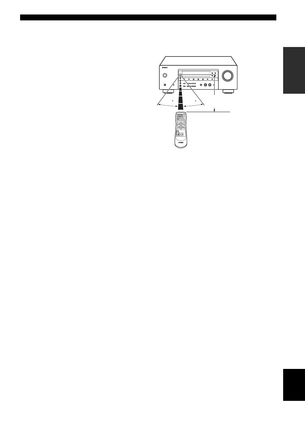
30 30
■ Using the remote control
The remote control transmits a directional infrared beam.
Be sure to aim the remote control directly at the remote
control sensor on the main unit during operation.
■ Handling the remote control
• Do not spill water or other liquids on the remote
control.
• Do not drop the remote control.
• Do not leave or store the remote control in the
following types of conditions:
– high humidity such as near a bath
– high temperature such as near a heater or stove
–extremely low temperature
– dusty places
CONTROLS AND FUNCTIONS
Approximately 6 m
r SLEEP
Sets the sleep timer.
t NIGHT
Sets the unit in night listening mode.
y STEREO
Switches between normal stereo and DSP effect
reproduction. When you select STEREO the unit mixes
down all Dolby Digital and DTS signals (except the LFE
channel) as well as those 2-channel signals without effect
sounds, to the front left and right speakers.
u VOLUME +/–
Increases or decreases the volume level.
i SET MENU
Selects the set menu mode.
8
V-AUX
VCR
DTV/CBL
DVD
MD/CD-R
TUNER
CD
MATRIX
DIGITAL
PCM
PL
PL
SILENT CINEMA
DSP
HiFi
NIGHT
VIRTUAL
A B
SP
STEREO
VOLUME
MUTE
MEMORY
TUNED
L
C
R
SL
LFE
SB
SR
~~~~~~~~~~~~~~
dB
dB
ft
CTRTPTYPS
HOLD AUTOPTY
EON
SLEEP
13
45
8
7
62
90qw yurt ieop
a
s
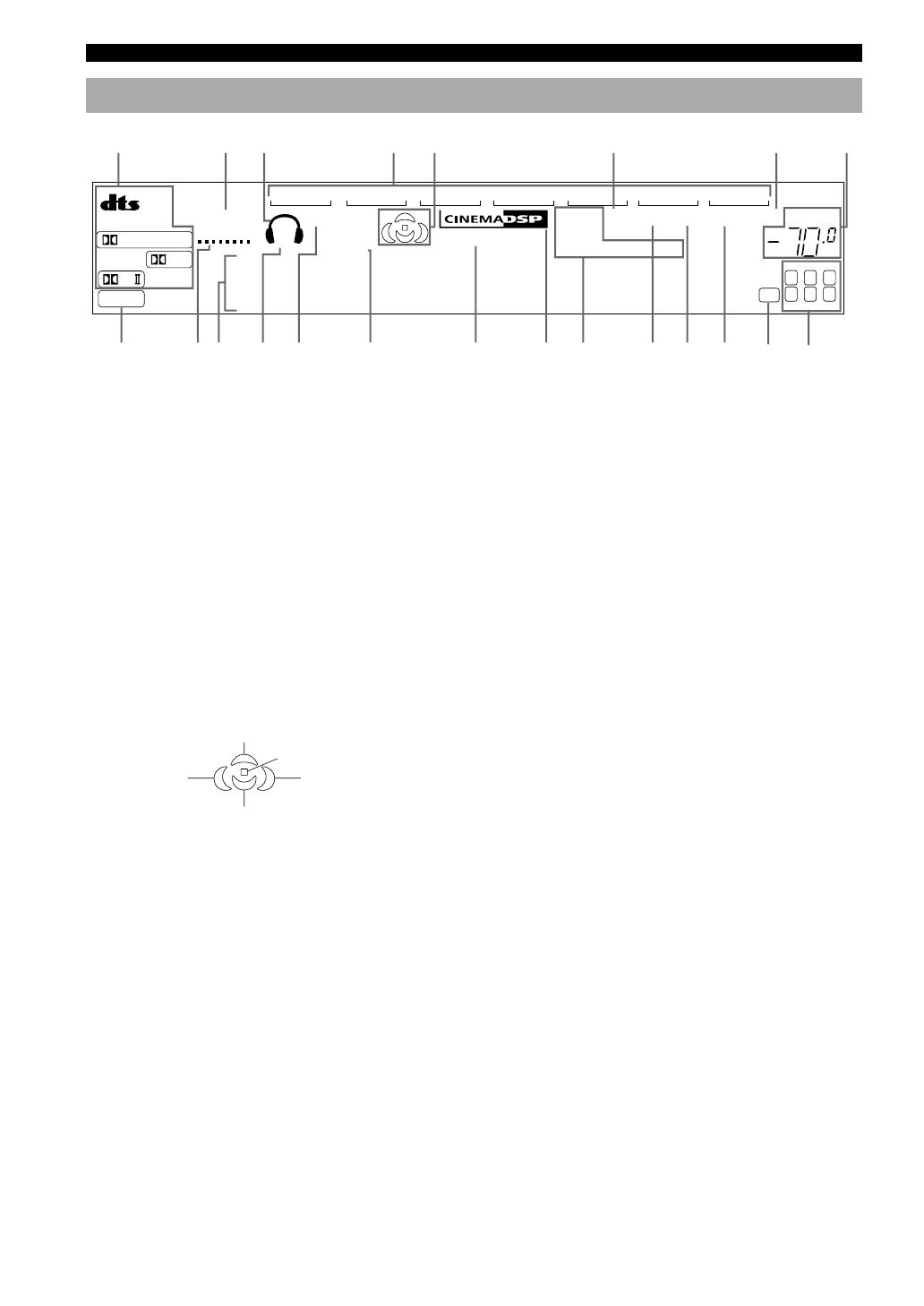
1 Decoder indicators
When any of this unit’s decoders function, the respective
indicator lights up.
2 SILENT CINEMA indicator
Lights up when headphones are connected and a sound
field program is selected (see page 27).
3 Headphones indicator
Lights up when headphones are connected to the
headphone jack.
4 Input source indicator
Highlights the current input source with a cursor.
5 Sound field indicator
Light to indicate the active DSP sound fields.
6 AUTO indicator
Shows that this unit is in the automatic tuning mode.
7 MUTE indicator
Flashes while the MUTE function is on.
8 VOLUME level indicator
Indicates the volume level.
9 PCM indicator
Lights up when this unit is reproducing PCM (pulse code
modulation) digital audio signals.
0 VIRTUAL indicator
Lights up when using Virtual CINEMA DSP.
q Multi-information display
Shows the current sound field program name and other
information when adjusting or changing settings.
w SP A B indicator
Lights up to indicate which set of front speakers is
selected.
e NIGHT indicator
Lights up when the unit is set to night listening mode.
r SLEEP indicator
Lights up while the sleep timer is on.
t HiFi DSP indicator
Lights up when you select a HiFi DSP sound field
program.
y CINEMA DSP indicator
Lights up when you select a CINEMA DSP sound field
program.
u Radio Data System indicators
The name(s) of the Radio Data System data offered by the
currently received Radio Data System station light(s) up.
EON lights up when an Radio Data System station that
offers the EON data service is being received.
PTY HOLD lights up while searching for stations in the
PTY SEEK mode.
i TUNED indicator
Lights up when this unit is tuned to a radio station.
o STEREO indicator
Lights up when the unit is receiving a strong signal from
an FM stereo broadcast while the “AUTO” indicator is lit.
p MEMORY indicator
Flashes to show a station can be stored.
a LFE indicator
Lights up when the input signal contains an LFE signal.
s Input channel indicators
The indicators for the appropriate sound channels light up
when a digital signal from a source is played back.
Front panel display
CONTROLS AND FUNCTIONS
Presence DSP sound field
Listening position
Right surround
DSP sound field
Surround back DSP sound field
Left surround
DSP sound field
9
PREPARATION
English
DIGITAL
INPUT
6CH INPUT AUDIO VIDEO SPEAKERS
AUDIO OUTPUT
L
DVD
R
LR
FRONT
SURROUND
SUB
WOOFER
CD
DTV
/CBL
COAXIAL
OPTICAL
CD
IN
(PLAY)
MD
/CD-R
OUT
(REC)
DTV
/CBL
V-AUX
IN
VCR
OUT
SUB
WOOFER
MONITOR
OUT
DVD
3
2
1
L
FRONT
A
B
R
L
SURROUND
R
L
FRONT
CENTER
R
TUNER
AM
ANT
FM
ANT
GND
75
Ω
UNBAL.
COMPONENT VIDEO
P
R
DVD
MONITOR
OUT
DTV
/CBL
P
B
Y
CENTER
CLASS 2 WIRING
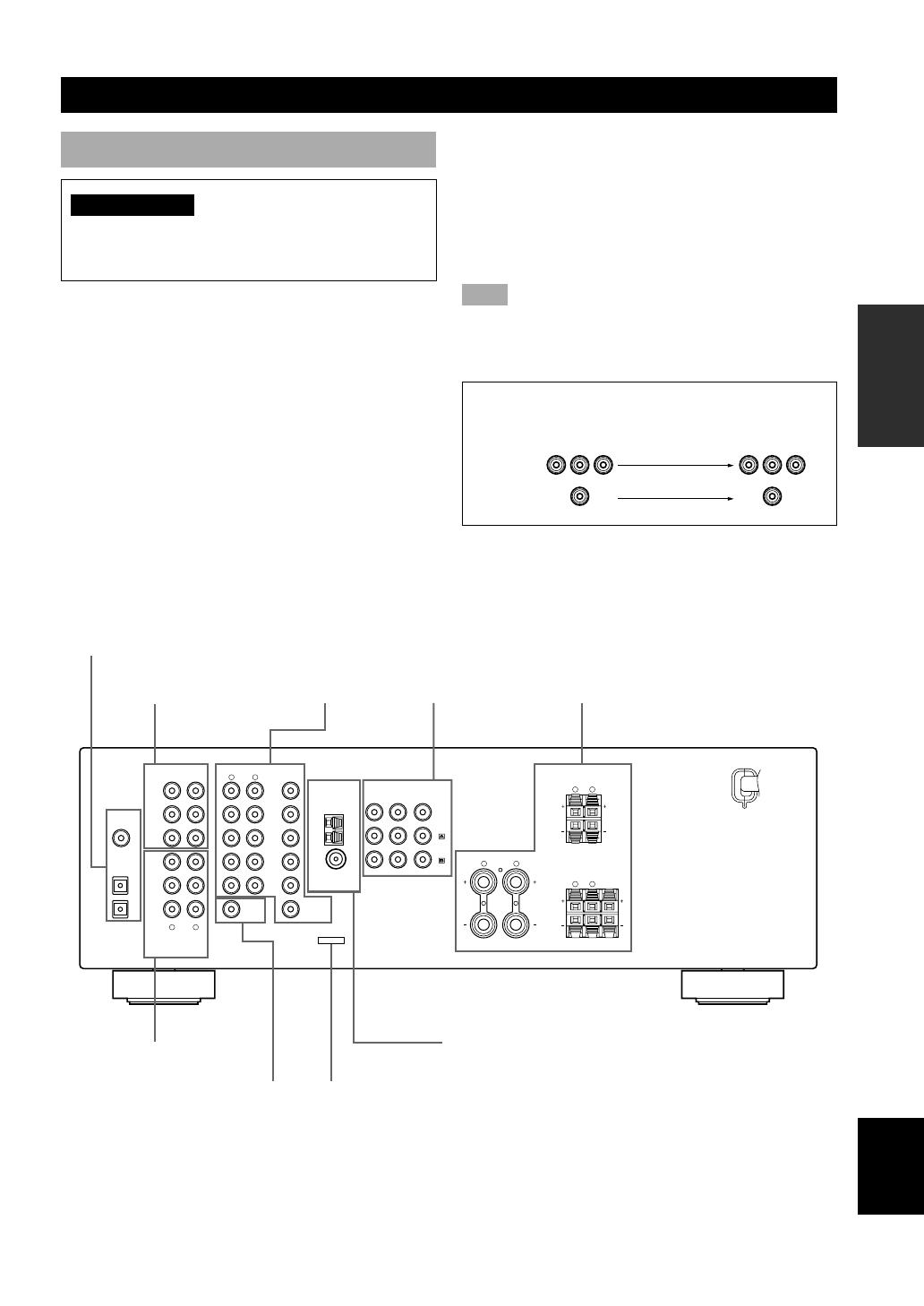
CONNECTIONS
Audio component jacks
(page 12)
DIGITAL INPUT jacks
(pages 9 – 12)
Antenna input terminals
(page 13)
Speaker terminals
(page 17)
Video component
jacks (page 10)
6CH INPUT jacks
(page 14)
SUBWOOFER OUTPUT
jack (page 17)
This jack is reserved for factory use.
Do not connect any equipment to this jack.
Before connecting components
CAUTION
Do not connect this unit or other components to the
mains power until all connections between the
components have been completed.
• Be sure to connect the left channel (L), right channel
(R), “+” (red) and “–” (black) properly. Some
components require different connection methods and
have different jack names. Refer to the operation
instructions for each component you wish to connect to
this unit.
• After you have completed all connections, check them
again to make sure they are correct.
• The jack names correspond to the names on the input
selector.
■ Connecting to digital jacks
This unit has digital jacks for direct transmission of
digital signals through either a coaxial or fiber optic
cable. You can use the digital jacks to input PCM, Dolby
Digital and DTS bitstreams. Use digital connections if
you wish to enjoy the multi-channel sound track of DVD
material, etc. with DSP effects. Both digital input jacks
are acceptable for 96 kHz sampling digital signals.
Note
• The OPTICAL jack on this unit conform to the EIA standard.
If you use a fiber optic cable that does not conform to EIA
standard, this unit may not function properly.
Signal flow inside this unit
Input
Output
(MONITOR OUT)
VIDEO
COMPONENT
VIDEO
COMPONENT
VIDEO jacks
(page 11)
10
DIGITAL
INPUT
6CH INPUT
AUDIO OUTPUT
AUDIO VIDEO
L
DVD
R
LR
FRONT
SURROUND
SUB
WOOFER
CENTER
CD
DTV
/CBL
COAXIAL
OPTICAL
CD
IN
(PLAY)
MD
/CD-R
OUT
(REC)
DTV
/CBL
V-AUX
IN
VCR
OUT
SUB
WOOFER
MONITOR
OUT
DVD
3
2
1
TUNER
AM
ANT
FM
ANT
GND
75
Ω
UNBAL.
COMPONE
PB
Y
VIDEO
INPUT
AUDIO
OUTPUT
LR
AUDIO
INPUT
LR
O
OPTICAL
OUTPUT
VIDEO
OUTPUT
AUDIO
OUTPUT
L
V
R
V V
AUDIO
OUTPUT
L R
VIDEO
OUTPUT
V
O
OPTICAL
OUTPUT
AUDIO
OUTPUT
L R
VIDEO
OUTPUT
V
V
VIDEO
INPUT
VIDEO
OUTPUT
O
L
R
V
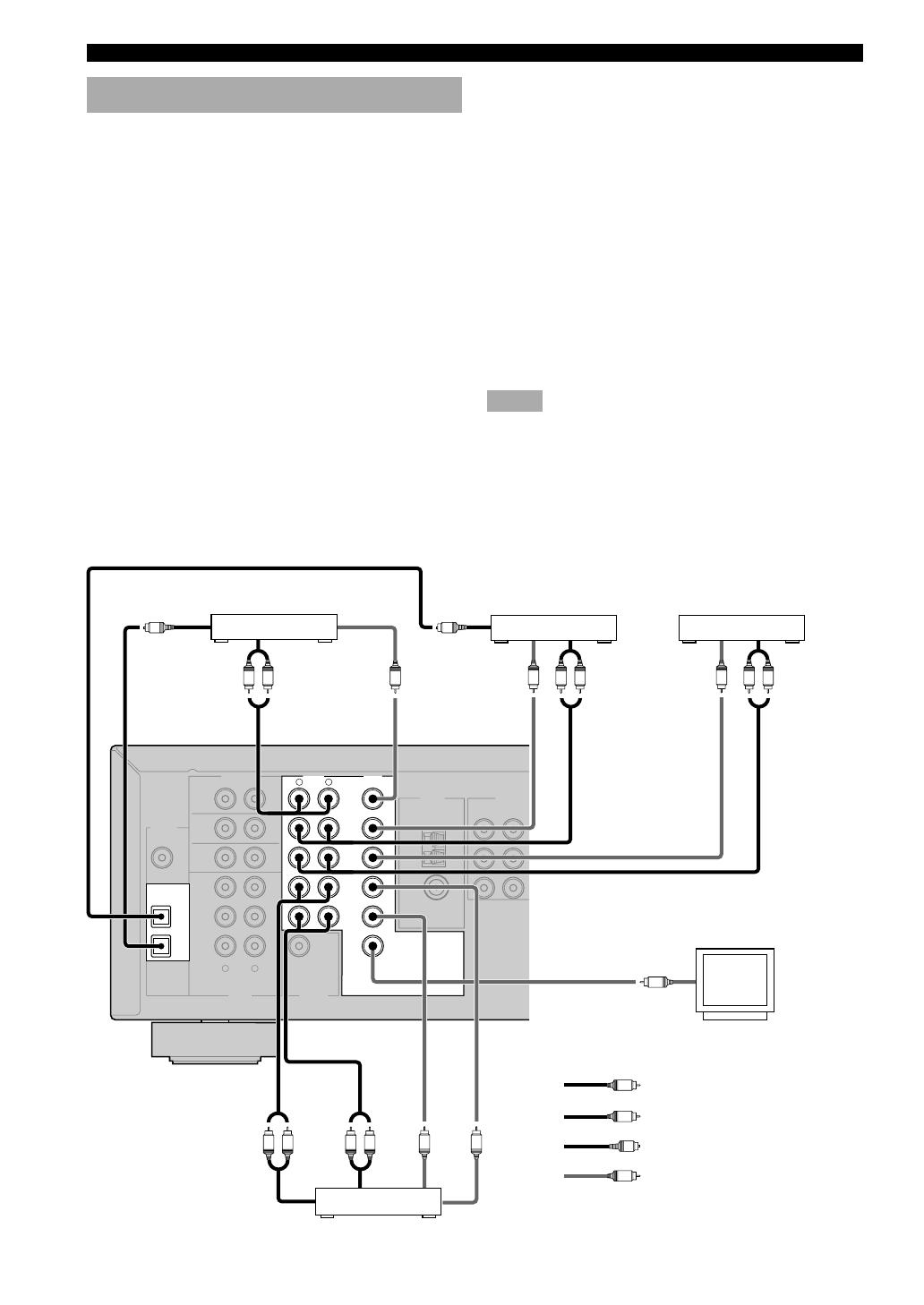
Connecting video components
■ Connecting a video monitor
Connect the video input jack on your video monitor to the
MONITOR OUT VIDEO jack.
■ Connecting a DVD player/digital TV/cable
TV
Connect the optical digital audio signal output jack on
your component to the DIGITAL INPUT jack and
connect the video signal output jack on the component to
the VIDEO jack on this unit.
y
• Use the AUDIO jacks on this unit for a video component
which does not have optical digital output jack. However,
multi-channel reproduction cannot be obtained with audio
signals input from the AUDIO jacks. If you wish to enjoy the
surround sound, use q/DTS on the remote control (see page
26).
•You can also connect a video monitor, DVD player, digital TV,
and cable TV to this unit using the COMPONENT VIDEO
connections (see page 11).
■ Connecting another video component
Connect the video signal output jack on your component
to the VIDEO jack on this unit.
Connect the audio signal output jacks on the component
to the AUDIO jacks on this unit.
■ Connecting a recording component
Connect the audio signal input jacks on your video
component to the AUDIO OUT jacks on this unit. Then
connect the video signal input jack on the video
component to the VIDEO OUT jack on this unit for
picture recording.
Connect the audio signal output jacks on your component
to the AUDIO IN jacks on this unit. Then connect the
video signal output jack on the component to the VIDEO
IN jack on this unit to play a source from your recording
component.
Notes
• Once you have connected a recording component to this unit,
keep its power turned on while using this unit. If the power is
off, this unit may distort the sound from other components.
• If you connect your video monitor to this unit using a VIDEO
connection, connect your video source components such as a
DVD player or digital TV to this unit using the VIDEO
connections.
Video monitor
DVD player
TV/digital TV/
cable TV
CONNECTIONS
Another video
component
indicates right analog cables
indicates left analog cables
VCR
indicates optical cables
indicates video cables
11
PREPARATION
English
COMPONENT VIDEO
PR
DVD
MONITOR
OUT
DTV
/CBL
PB
Y
COMPONENT
VIDEO
Y
P
B
P
R
Y
P
B
P
R
Y
P
B
P
R
Y
P
B
P
R
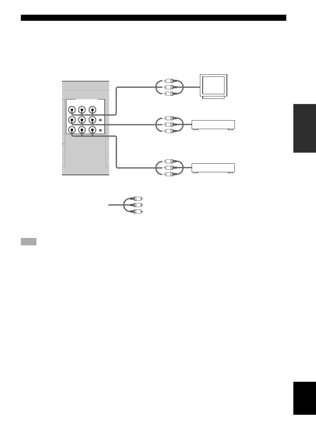
■ COMPONENT VIDEO jacks
You can enjoy high-quality pictures by connecting your
video monitor and video source components to this unit
using COMPONENT VIDEO connections.
Note
• If you connect your video monitor to this unit using a
COMPONENT VIDEO connection, connect your video
source components such as a DVD player or digital TV to this
unit using COMPONENT VIDEO connections.
indicates component video cables
DVD player
Digital TV/cable TV
Video monitor
CONNECTIONS
12
6CH INPUT AUDIO VIDEO
OUTPUT
DIGITAL
INPUT
AUDIO
L
DVD
R
LR
FRONT
SURROUND
SUB
WOOFER
CENTER
CD
DTV
/CBL
COAXIAL
OPTICAL
CD
IN
(PLAY)
MD
/CD-R
OUT
(REC)
DTV
/CBL
V-AUX
IN
VCR
OUT
SUB
WOOFER
MONITOR
OUT
DVD
2
3
1
TUNER
AM
ANT
FM
ANT
GND
75
Ω
UNBAL.
C
L
R
AUDIO
INPUT
L
R
AUDIO
OUTPUT
L
R
COAXIAL
OUTPUT
C
AUDIO
OUTPUT
L
R
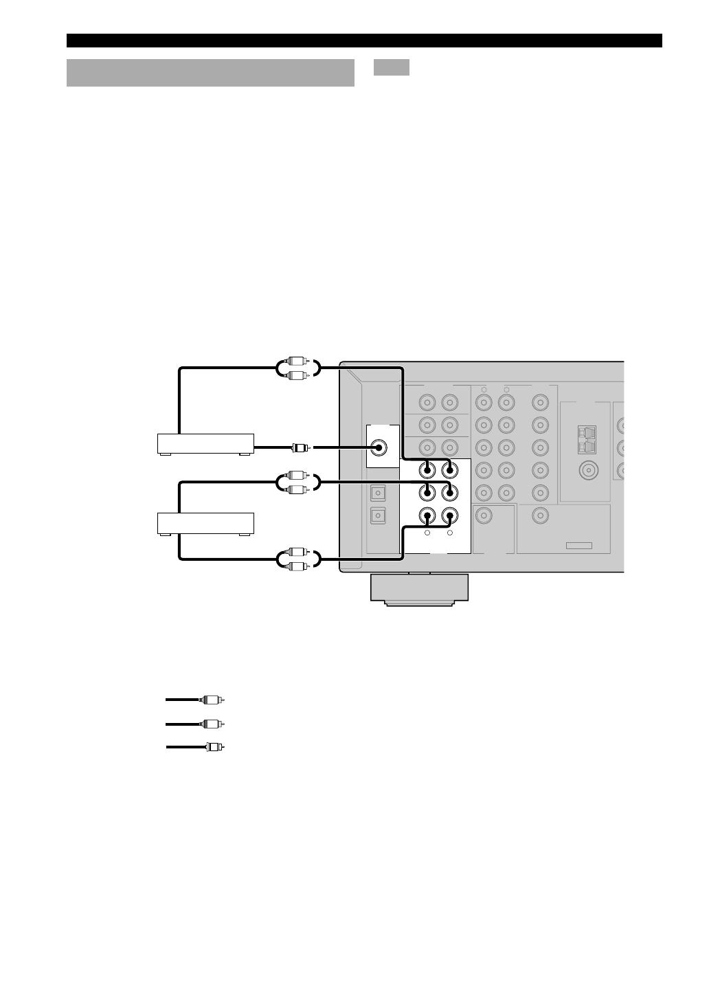
Connecting audio components
■ Connecting a CD player
Connect the coaxial digital output jack on your CD player
to the DIGITAL INPUT CD jack on this unit.
y
• Use the AUDIO jacks on this unit to connect to a CD player
that does not have a COAXIAL DIGITAL OUTPUT jack, or
to record from CD players.
■ Connecting a CD recorder or MD
recorder
Connect the input jacks on your CD recorder or MD
recorder to the MD/CD-R OUT (REC) jacks.
Connect the output jacks on your CD recorder or MD
recorder to the MD/CD-R IN (PLAY) jacks to play a
source from your recording component.
CD player
CD recorder or
MD recorder
CONNECTIONS
Note
• Once you have connected a recording component to this unit,
keep its power turned on while using this unit. If the power is
off, this unit may distort the sound from other components.
indicates right analog cables
indicates left analog cables
indicates coaxial cables
13
PREPARATION
English
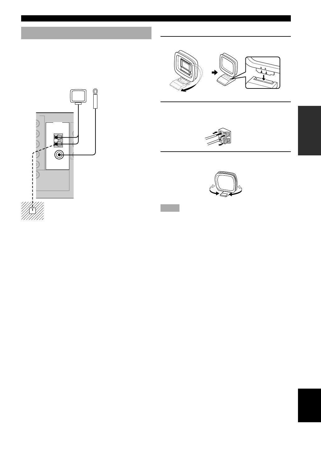
■ Connecting the AM loop antenna
1 Set up the AM loop antenna.
2 Press and hold the tab to insert the AM loop
antenna lead wires into the AM ANT and
GND terminals.
3 Orient the AM loop antenna for the best
reception.
Notes
•The AM loop antenna should be placed away from this unit.
•The AM loop antenna should always be connected, even if an
outdoor AM antenna is connected to this unit.
•A properly installed outdoor antenna provides clearer
reception than an indoor one. If you experience poor reception
quality, an outdoor antenna may improve the quality. Consult
the nearest authorized YAMAHA dealer or service center
about the outdoor antennas.
Ground (GND terminal)
For maximum safety and minimum
interference, connect the antenna GND
terminal to a good earth ground. A good
earth ground is a metal stake driven into
moist earth.
Indoor FM
antenna
(included)
AM loop antenna
(included)
Connecting the antennas
Both AM and FM indoor antennas are included with this
unit. In general, these antennas should provide sufficient
signal strength.
Connect each antenna correctly to the designated
terminals.
CONNECTIONS
TUNER
AM
ANT
FM
ANT
GND
75
Ω
UNBAL.
EO
MONITOR
OUT
14
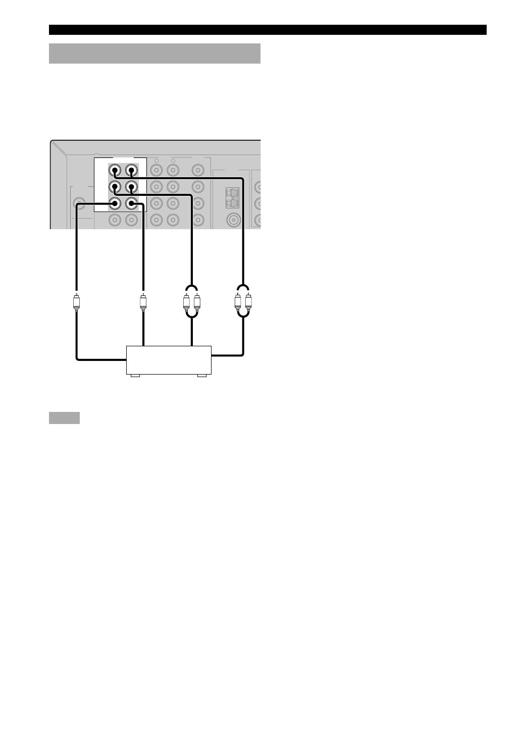
Connecting an external decoder
This unit is equipped with 6 additional input jacks
(FRONT left and right, CENTER, SURROUND left and
right and SUBWOOFER) for discrete multi-channel input
from a component equipped with a multi-channel decoder
and 6 channel output jacks such as a DVD/Super Audio
CD player.
Notes
• When you select 6CH INPUT as the input source, this unit
automatically turns off the digital sound field processor, and
you cannot select sound field programs.
• When headphones are used, only front L/R channels are
output.
DIGITAL
INPUT
AUDIO VIDEO
6CH INPUT
L
DVD
R
FRONT
SURROUND
SUB
WOOFER
CENTER
CD
DTV
COAXIAL
OPTICAL
CD
DTV
/CBL
V-AUX
IN
3
TUNER
AM
ANT
FM
ANT
GND
L R
LR
SUBWOOFER FRONT
CENTER SURROUND
SUBWOOFER
CENTER SURROUND
CONNECTIONS
DVD/Super Audio CD player
15
PREPARATION
English
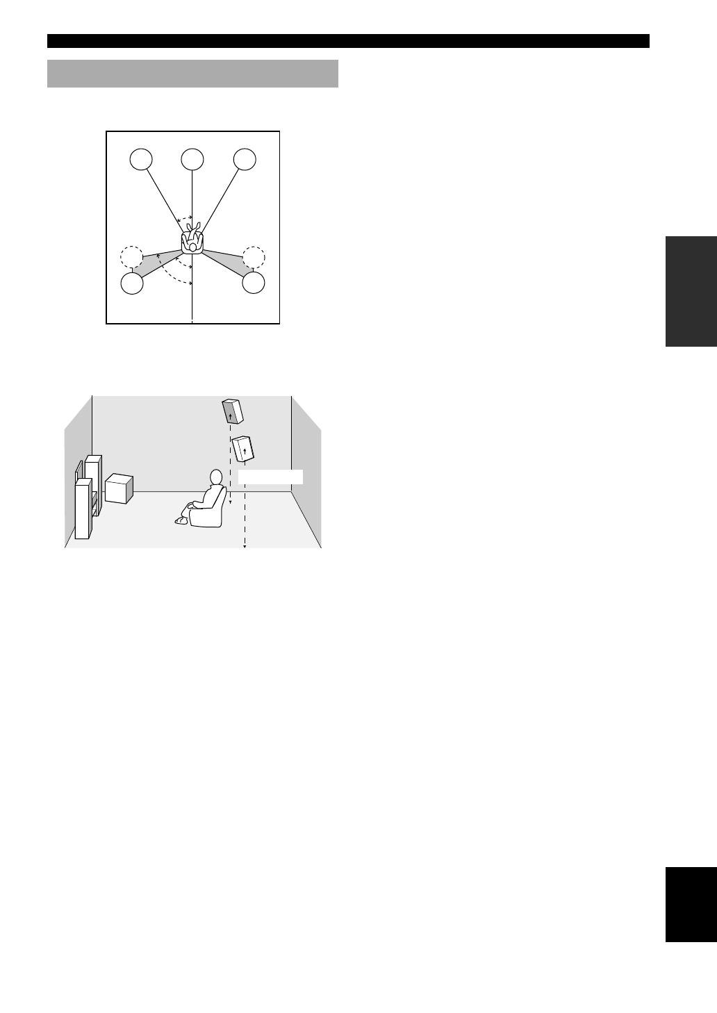
Connecting the speakers
■ Speaker placement
60˚
30˚
FL
FR
C
SL
SR
SR
80˚
SL
The speaker layout above shows the standard ITU-R
speaker setting. You can use it to enjoy CINEMA DSP,
multi-channel audio sources.
1.8 m
Front speakers (FR and FL)
The front speakers are used for the main source sound
plus effect sounds. Place these speakers an equal distance
from the ideal listening position. The distance of each
speaker from each side of the video monitor should be the
same.
Center speaker (C)
The center speaker is for the center channel sounds
(dialog, vocals, etc.). If for some reason it is not practical
to use a center speaker, you can do without it.
Best results, however, are obtained with the full system.
Align the front face of the center speaker with the front
face of your video monitor. Place the speaker centrally
between the front speakers and as close to the monitor as
possible, such as directly over or under it.
Surround speakers (SR and SL)
The surround speakers are used for effect and surround
sounds. Place these speakers behind your listening
position, facing slightly inwards, about 1.8 m above the
floor.
CONNECTIONS
Subwoofer (SWFR)
The use of a subwoofer, such as the YAMAHA Active
Servo Processing Subwoofer System, is effective not only
for reinforcing bass frequencies from any or all channels,
but also for high fidelity reproduction of the LFE
(low-frequency effect) channel included in Dolby Digital
and DTS software. The position of the subwoofer is not
so critical, because low bass sounds are not highly
directional. But it is better to place the subwoofer near the
front speakers. Turn it slightly toward the center of the
room to reduce wall reflections.
16
CONNECTIONS
■ Speaker connections
Be sure to connect the left channel (L), right channel (R), “+” (red) and “–” (black) properly. If the connections are
faulty, no sound will be heard from the speakers, and if the polarity of the speaker connections is incorrect, the sound
will be unnatural and lack bass.
CAUTION
• Use speakers with the specified impedance shown on the rear panel of this unit.
• Before connecting the speakers, make sure that the power of this unit is off.
• Do not let the bare speaker wires touch each other or do not let them touch any metal part of this unit. This could
damage this unit and/or speakers.
• Use magnetically shielded speakers. If this type of speakers still creates the interference with the monitor, place
the speakers away from the monitor.
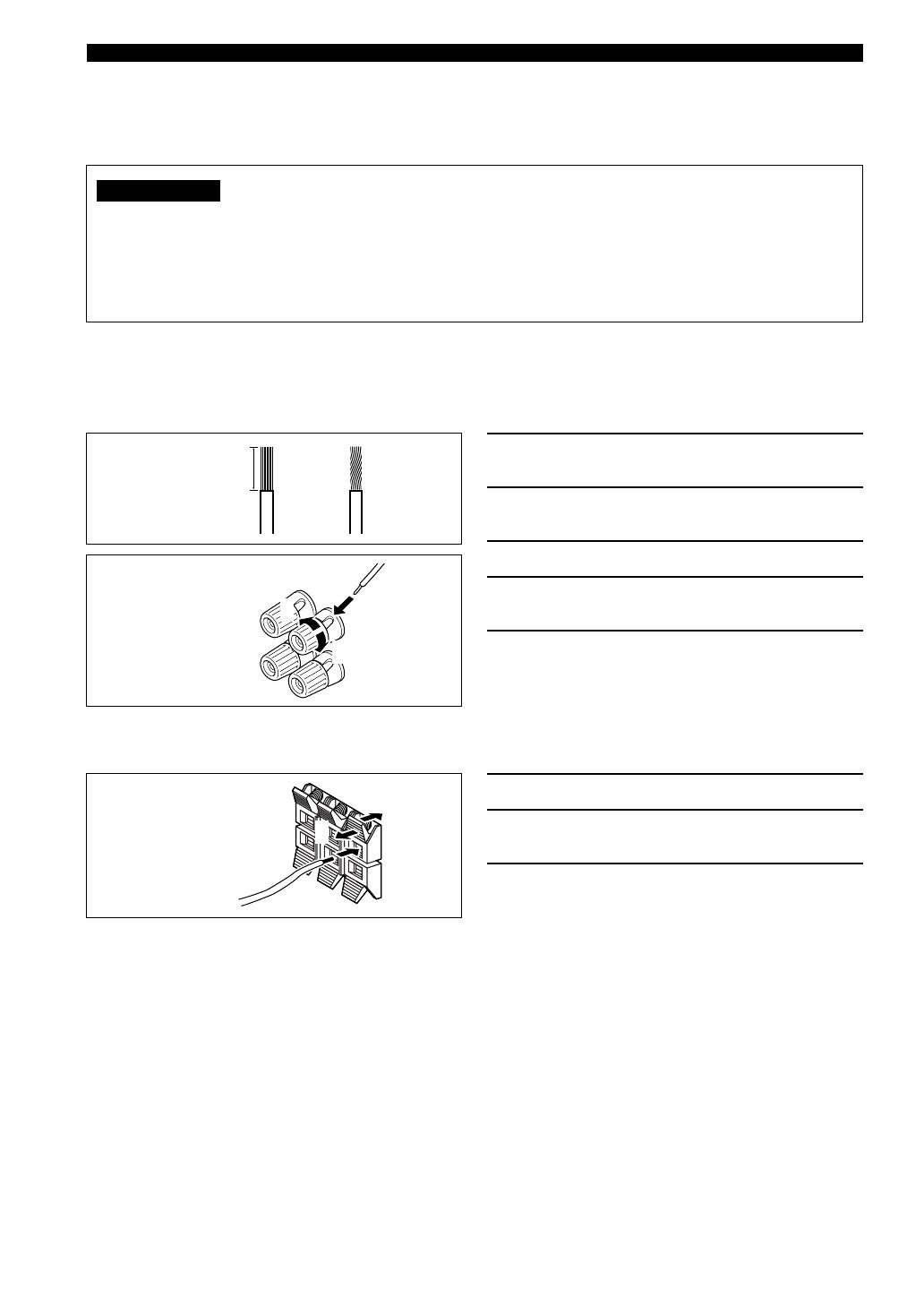
Connecting to the FRONT A SPEAKERS terminals
A speaker cord is actually a pair of insulated cables running side by side. One cable is colored or shaped differently,
perhaps with a stripe, groove or ridges. Connect the striped (grooved, etc.) cable to the “+” (red) terminals on this unit
and your speaker. Connect the plain cable to the “–” (black) terminals.
Connecting to the FRONT B, CENTER and SURROUND SPEAKERS terminals
1 Remove approximately 10 mm of insulation
from the end of each of the speaker cables.
2 Twist the exposed wires of the cable
together to prevent short circuits.
3 Loosen the head of the screw.
4 Insert one bare wire into the hole in the side
of each terminal.
5 Tighten the head of the screw to secure the
wire.
1 Press and open the tab.
2 Insert one bare wire into the hole of each
terminal.
3 Release the tab to secure the wire.
10 mm
12
Red: positive (+)
Black: negative (–)
3
4
5
3
1
2
Red: positive (+)
Black: negative (–)
17
PREPARATION
English
Subwoofer with
built-in amplifier
Surround speaker
Center
speaker
Right
Front B speaker
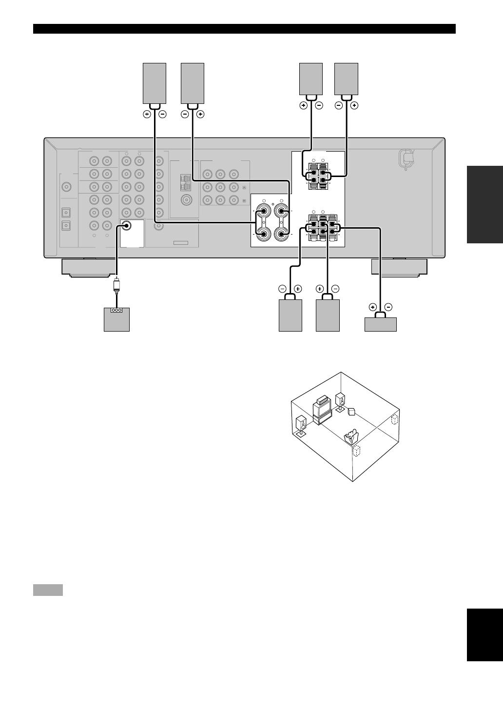
SUBWOOFER jack
When using a subwoofer with built-in amplifier, including the YAMAHA Active Servo Processing Subwoofer System,
connect the input jack of the subwoofer system to this jack. This unit will direct low bass signals distributed from the
front, center and/or surround channels to this jack in accordance with your SPEAKER SET selections. The LFE (low-
frequency effect) signals generated when Dolby Digital or DTS is decoded are also directed to this jack in accordance
with your SPEAKER SET selections.
Notes
•The cut-off frequency of the SUBWOOFER jack is 90 Hz.
• If you do not use a subwoofer, allocate the signals to the front left and right speakers by changing the setting of “SOUND 1
SPEAKER SET” item “1D BASS” on the set menu to FRONT.
• Use the control on the subwoofer to adjust its volume level. You can also adjust the volume level by using this unit’s remote control
(see “SETTING THE SPEAKER LEVELS” on page 47).
Right Left
Front A speaker
Right Left Left
FRONT SPEAKERS terminals
You can connect up to two speaker systems to these
terminals. When using only one speaker system, connect
it to either of the FRONT A or the FRONT B terminals.
SURROUND SPEAKERS terminals
A surround speaker system can be connected to these
terminals.
CENTER SPEAKER terminals
A center speaker can be connected to these terminals.
CONNECTIONS
The diagram shows the speaker layout in the listening
room.
DIGITAL
INPUT
6CH INPUT AUDIO VIDEO SPEAKERS
AUDIO OUTPUT
L
DVD
R
LR
FRONT
SURROUND
SUB
WOOFER
CENTER
CD
DTV
/CBL
COAXIAL
OPTICAL
CD
IN
(PLAY)
MD
/CD-R
OUT
(REC)
DTV
/CBL
V-AUX
IN
VCR
OUT
SUB
WOOFER
MONITOR
OUT
DVD
3
2
1
L
FRONT
A
B
R
L
SURROUND
R
L
FRONT
CENTER
R
CLASS 2 WIRING
TUNER
AM
ANT
FM
ANT
GND
75Ω
UNBAL.
COMPONENT VIDEO
PR
DVD
MONITOR
OUT
DTV
/CBL
PB
Y
3
65
21
4
18
L
RROUND
)
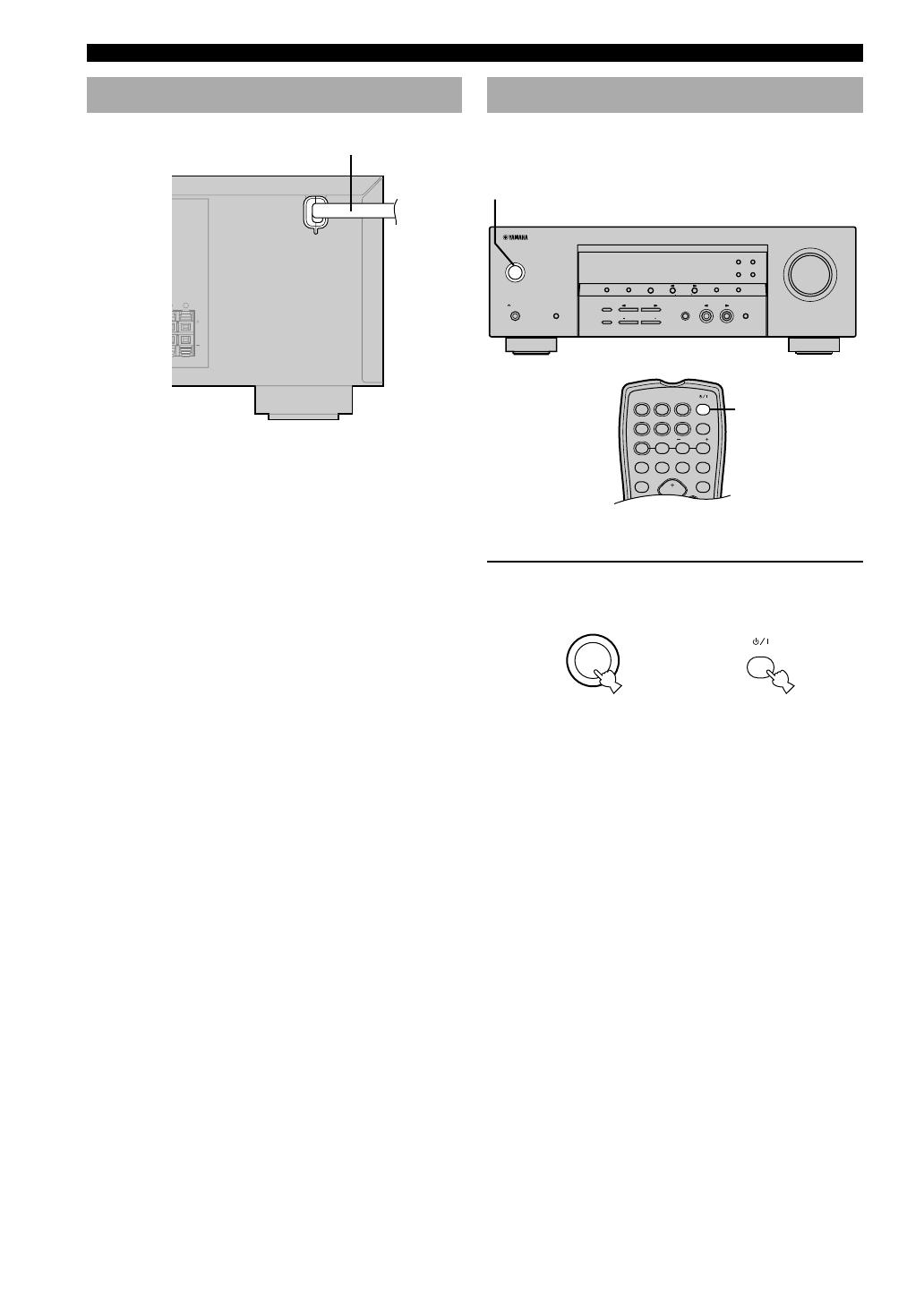
Turning on the power
When all connections are complete, turn on the power of
this unit.
1 Press STANDBY/ON (or POWER on the
remote control) to turn on the power of this
unit.
The level of the volume, and then the current sound
field program name appear on the front panel
display.
or
Remote control
Front panel
PRESET/TUNING
EDIT
FM/AM A/B/C/D/E
NEXT
PRESET/TUNING
INPUT MODE 6CH INPUT
SET MENU
MEMORY
MAN’L/AUTO FM
TUNING MODE
AUTO/MAN’L MONO
FREQ/TEXT EON
PTY SEEK
MODE START
VOLUME
STEREO PROGRAM INPUT
EFFECT
TONE CONTROL
BASS/TREBLE
STANDBY
/ON
PHONES
SILENT CINEMA
SPEAKERS
A/B/OFF
1
TEST
PROG PROG
STEREO
TUNER
CD MD/CD-R V-AUX 6CH IN
q
/DTS 6.1/5.1
NIGHT SLEEP
DVD D-TV/CBL VCR
PRESETA/B/C/D/E
VOLUME
POWER
STANDBY
/ON
POWER
Connecting the power supply cord
■ Connecting the AC power cord
Plug the power cord into an AC wall outlet.
CONNECTIONS
Power cord
Основные и самые важные характеристики модели собраны из надежных источников и по характеристикам можно найти похожие модели.
| Общие характеристики | ||
| Тип | AV-ресивер, 5.1 | |
| Количество каналов | 5 | |
| Схемотехника | полупроводниковый | |
| Параметры усилителя | ||
| Мощность фронтальных каналов | 110 Вт (6 Ом, 1000 Гц, 10%), 100 Вт (6 Ом, 1000 Гц, 0.7%), 105 Вт (6 Ом) | |
| Мощность фронтальных каналов (многоканальный режим) | 110 Вт | |
| Мощность центрального канала | 110 Вт | |
| Мощность тыловых каналов | 110 Вт | |
| Воспроизводимый диапазон частот | 10 — 100000 Гц ( 0/-3 дБ) | |
| Коэффициент гармоник | 0.06 % (1 кГц, 50 Вт, 6 Ом) | в режиме FM моно: 0.50 %, в режиме FM стерео: 0.50 % |
| Отношение сигнал/шум | 100 дБ | в режиме FM моно: 73 дБ, в режиме FM стерео: 70 дБ |
| Регулировки | ||
| Регулировка тембра | есть | |
| Эквалайзер | есть | |
| Цифровая обработка звука | ||
| DSP | есть | |
| Частота дискретизации аудио ЦАП | 192 кГц | |
| Разрядность аудио ЦАП | 24 бит | |
| Количество предустановок DSP | 14 | |
| Интерфейсы | ||
| Входы | композитный x4, компонентный x2, коаксиальный x1, оптический x2, 5.1CH x1, линейный x6 | |
| Выходы | сабвуфер x1, композитный x2, компонентный x1, наушники x1, линейный x2 | |
| Разъемы на передней панели | наушники | |
| Разъем для подключения наушников | 6.3 мм | |
| Разъемы для акустики | пружинные защелки | |
| Максимальная частота видеосигнала | 60 МГц | |
| Функции | ||
| Подключение дополнительных комплектов акустики | есть | |
| Декодеры | ||
| Dolby Digital | есть | |
| Dolby Pro Logic | есть | |
| Dolby Pro Logic II | есть | |
| DTS | есть | |
| DTS ES Matrix 6.1 | есть | |
| Тюнер | ||
| Тип тюнера | цифровой | |
| Режимы | AM/FM | |
| Количество станций | общее: 40 | |
| Диапазон частот AM | 530 — 1710 кГц | |
| Диапазон частот FM | 87.5 — 108 МГц | |
| Чувствительность | в режиме FM моно: 20.2 дБф | |
| Отношение сигнал/шум | 100 дБ | в режиме FM моно: 73 дБ, в режиме FM стерео: 70 дБ |
| Коэффициент гармоник | 0.06 % (1 кГц, 50 Вт, 6 Ом) | в режиме FM моно: 0.50 %, в режиме FM стерео: 0.50 % |
| Функции | автоматическая настройка, ручная настройка, RDS | |
| Питание | ||
| Блок питания | встроенный | |
| Потребляемая мощность в режиме ожидания | 0.5 Вт | |
| Конструкция | ||
| Дисплей | есть | |
| Цветовое оформление | черный, серебристый | |
| Размеры (ШхВхГ) | 435x151x315 мм | |
| Вес | 9 кг | |
| Дополнительная информация | ||
| Пульт ДУ | есть, управление другими компонентами, с режимом обучения | |
| Рекомендованные акустические системы | Yamaha NS-P440, Yamaha NS-P270 | |
| Особенности | винтовые разъемы для акустики в зоне «А» у передних колонок |