Материал из BikesWiki — энциклопедия японских мотоциклов
Перейти к: навигация, поиск

Yamaha XJR 1300
Ниже представлены прямые ссылки на скачку сервисной документации.
Для Yamaha XJR 1300
- Каталог запчастей (микрофиши) для Yamaha XJR 1300 (2002)
- Руководство пользователя (Owners Manual) для Yamaha XJR 1300 (2002, на русском)
- Руководство пользователя (Owners Manual) для Yamaha XJR 1300 (2007-2009)
- Сервисный мануал (Service Manual) для Yamaha XJR 1300 (1999)
- Руководство по ремонту и обслуживанию (Haynes Repair&Service Manual) для Yamaha XJR 1200-1300 (1995-2003)
- Сервисный мануал (Service Manual) для Yamaha XJR 1300 (2007)
Обзор модели
- Yamaha XJR 1300
Источник — «https://bikeswiki.ru/index.php?title=Yamaha_XJR1300:_мануалы&oldid=10066»
Категория:
- Сервисная документация
![]()
4-я Красноармейская, 2А
Санкт-Петербург, 190005
Email: info@lenmoto.ru
Телефон: +7 (921) 930-81-18
Телефон: +7 (911) 928-08-06
Компания ЛенМото
Запчасти, аксессуары, экипировка, тюнинг для мотоциклов, скутеров, квадроциклов, снегоходов, багги, гидроциклов, катеров и лодочных моторов.
Подпишитесь на наши новости
Подписаться
-
Page 1
2007 XJR1300(W) SERVICE MANUAL 5WM-28197-E0… -
Page 3
EAS20040 XJR1300(W) 2007 SERVICE MANUAL ©2007 by Yamaha Motor Co., Ltd. First edition, February 2007 All rights reserved. Any reproduction or unauthorized use without the written permission of Yamaha Motor Co., Ltd. is expressly prohibited. -
Page 4
EAS20070 NOTICE This manual was produced by the Yamaha Motor Company, Ltd. primarily for use by Yamaha dealers and their qualified mechanics. It is not possible to include all the knowledge of a mechanic in one man- ual. Therefore, anyone who uses this book to perform maintenance and repairs on Yamaha vehicles should have a basic understanding of mechanics and the techniques to repair these types of vehicles. -
Page 5
EAS20090 HOW TO USE THIS MANUAL This manual is intended as a handy, easy-to-read reference book for the mechanic. Comprehensive explanations of all installation, removal, disassembly, assembly, repair and check procedures are laid out with the individual steps in sequential order. The manual is divided into chapters and each chapter is divided into sections. -
Page 6: Symbols
EAS20100 1. Serviceable with engine mounted SYMBOLS 2. Filling fluid The following symbols are used in this manual 3. Lubricant for easier understanding. 4. Special tool NOTE: 5. Tightening torque The following symbols are not relevant to every 6. Wear limit, clearance vehicle.
-
Page 7: Table Of Contents
EAS20110 TABLE OF CONTENTS GENERAL INFORMATION SPECIFICATIONS PERIODIC CHECKS AND ADJUSTMENTS CHASSIS ENGINE FUEL SYSTEM ELECTRICAL SYSTEM TROUBLESHOOTING…
-
Page 9: General Information
GENERAL INFORMATION IDENTIFICATION ………………1-1 VEHICLE IDENTIFICATION NUMBER ……….. 1-1 MODEL LABEL………………1-1 FEATURES………………..1-2 OUTLINE OF THE FI SYSTEM …………… 1-2 FI SYSTEM………………..1-3 IMMOBILIZER SYSTEM …………….. 1-4 INSTRUMENT FUNCTION …………..1-5 IMPORTANT INFORMATION …………… 1-8 PREPARATION FOR REMOVAL AND DISASSEMBLY……1-8 REPLACEMENT PARTS……………..
-
Page 10: Identification
IDENTIFICATION EAS20130 IDENTIFICATION EAS20140 VEHICLE IDENTIFICATION NUMBER The vehicle identification number “1” is stamped into the right side of the steering head pipe. EAS20150 MODEL LABEL The model label “1” is affixed to the frame. This information will be needed to order spare parts.
-
Page 11: Features
FEATURES EAS20170 FEATURES EAS5UXB014 OUTLINE OF THE FI SYSTEM The main function of a fuel supply system is to provide fuel to the combustion chamber at the optimum air-fuel ratio in accordance with the engine operating conditions and the atmospheric temperature. In the conventional carburetor system, the air-fuel ratio of the mixture that is supplied to the combustion chamber is created by the volume of the intake air and the fuel that is metered by the jet used in the respective carburetor.
-
Page 12: Fi System
FEATURES EAS5UXB016 FI SYSTEM The fuel pump delivers fuel to the fuel injector via the fuel filter. The pressure regulator is installed in the fuel rail, and maintains the fuel pressure that is applied to the fuel injector at 387 – 397 kPa (3.87 –…
-
Page 13: Immobilizer System
FEATURES EAS5UXB016 IMMOBILIZER SYSTEM To help prevent theft, the XJR1300 is equipped with an “immobilizer system” that electronically pre- vents engine starting. The key has a built-in microchip transponder that disables illegal duplicate keys by dual checking of code between key and immobilizer unit and between immobilizer unit and ECU, thereby improving se- curity.
-
Page 14: Instrument Function
FEATURES Odometer and trip meter modes EAS5UXB003 INSTRUMENT FUNCTION Multi-function display EWA5UXB001 WARNING Be sure to stop the motorcycle before mak- ing any setting change to the multi-function display. 1. Odometer/Trip meter/Fuel trip meter Pushing the “SELECT” button switches the dis- play between the odometer mode “ODO”…
-
Page 15
FEATURES Fuel meter Self-diagnosis devices 1. Error code display 1. Fuel level warning indicator 2. Fuel meter This model is equipped with a self-diagnosis de- vice for various electrical circuits. The fuel meter indicates the amount of fuel in the If any of those circuits are defective, the engine fuel tank. -
Page 16
FEATURES ECA5UXB016 CAUTION: If the multi-function display indicates an er- ror code, the vehicle should be checked as soon as possible in order to avoid engine damage. -
Page 17: Important Information
Oil bearings liberally when installing, if appropri- EAS20200 ate. REPLACEMENT PARTS Use only genuine Yamaha parts for all replace- ments. Use oil and grease recommended by Yamaha for all lubrication jobs. Other brands may be similar in function and appearance, but…
-
Page 18: Circlips
IMPORTANT INFORMATION ECA13300 CAUTION: Do not spin the bearing with compressed air because this will damage the bearing surfac- 1. Bearings EAS20240 CIRCLIPS Before reassembly, check all circlips carefully and replace damaged or distorted circlips. Al- ways replace piston pin clips after one use. When installing a circlip “1”, make sure the sharp-edged corner “2”…
-
Page 19: Checking The Connections
CHECKING THE CONNECTIONS EAS20250 CHECKING THE CONNECTIONS Pocket tester 90890-03112 Check the leads, couplers, and connectors for Analog pocket tester stains, rust, moisture, etc. YU-03112-C 1. Disconnect: Lead NOTE: Coupler If there is no continuity, clean the terminals. Connector When checking the wire harness, perform 2.
-
Page 20: Special Tools
SPECIAL TOOLS EAS20260 SPECIAL TOOLS The following special tools are necessary for complete and accurate tune-up and assembly. Use only the appropriate special tools as this will help prevent damage caused by the use of inappropriate tools or improvised techniques. Special tools, part numbers or both may differ depending on the country. When placing an order, refer to the list provided below to avoid any mistakes.
-
Page 21
SPECIAL TOOLS Reference Tool name/Tool No. Illustration pages Pocket tester 1-10, 5-31, 90890-03112 5-35, 6-8, 7-83, 7-85, 7-86, Analog pocket tester 7-90, 7-91, YU-03112-C 7-93, 7-94, 7-95, 7-96, 7-97, 7-98, 7-99 Timing light 3-11 90890-03141 Inductive clamp timing light YU-03141 Digital circuit tester 6-8, 6-10 90890-03174… -
Page 22
5-20 90890-04101 Valve lapping tool YM-A8998 Tappet adjusting tool 90890-04110 Valve adjustment tool YM-33966 Ignition checker 7-92 90890-06754 Opama pet-4000 spark checker YM-34487 Yamaha bond No. 1215 (Three Bond 5-63 No.1215®) 90890-85505 Digital tachometer 3-7, 3-9, 3-11 90890-06760 YU-39951-B 1-13… -
Page 23: Specifications
SPECIFICATIONS GENERAL SPECIFICATIONS …………..2-1 ENGINE SPECIFICATIONS …………….2-2 CHASSIS SPECIFICATIONS ……………. 2-9 ELECTRICAL SPECIFICATIONS …………..2-12 TIGHTENING TORQUE…………….. 2-15 GENERAL TIGHTENING TORQUE SPECIFICATIONS ……2-15 ENGINE ………………..2-15 CHASSIS ………………..2-18 LUBRICATION POINTS AND LUBRICANT TYPES ……..2-21 ENGINE ………………..2-21 CHASSIS ………………..
-
Page 24: General Specifications
GENERAL SPECIFICATIONS EAS20280 GENERAL SPECIFICATIONS Model Model 5WMG (EUR) 5WMJ (OCE) Dimensions Overall length 2175 mm (85.6 in) Overall width 765 mm (30.1 in) Overall height 1115 mm (43.9 in) Seat height 795 mm (31.3 in) Wheelbase 1500 mm (59.1 in) Ground clearance 125 mm (4.92 in) Minimum turning radius…
-
Page 25: Engine Specifications
ENGINE SPECIFICATIONS EAS20290 ENGINE SPECIFICATIONS Engine Engine type Air cooled 4-stroke, DOHC Displacement 1251.0 cm Cylinder arrangement Forward-inclined parallel 4-cylinder Bore × stroke 79.0 × 63.8 mm (3.11 × 2.51 in) Compression ratio 9.70 :1 Standard compression pressure (at sea level) 1050 kPa/400 r/min (149.3 psi/400 r/min) (10.5 kgf/cm /400 r/min)
-
Page 26
ENGINE SPECIFICATIONS Volume 33.90–34.70 cm (2.07–2.12 cu.in) Warpage limit 0.20 mm (0.0079 in) Camshaft Drive system Chain drive (center) Camshaft cap inside diameter 25.000–25.021 mm (0.9843–0.9851 in) Camshaft journal diameter 24.967–24.980 mm (0.9830–0.9835 in) Camshaft-journal-to-camshaft-cap clearance 0.020–0.054 mm (0.0008–0.0021 in) Camshaft lobe dimensions Intake A 35.849–35.949 mm (1.4114–1.4153 in) -
Page 27
ENGINE SPECIFICATIONS Valve seat width C (intake) 0.90–1.10 mm (0.0354–0.0433 in) Valve seat width C (exhaust) 0.90–1.10 mm (0.0354–0.0433 in) Valve margin thickness D (intake) 0.80–1.20 mm (0.0315–0.0472 in) Valve margin thickness D (exhaust) 0.80–1.20 mm (0.0315–0.0472 in) Valve stem diameter (intake) 5.475–5.490 mm (0.2156–0.2161 in) Limit 5.445 mm (0.2144 in) -
Page 28
ENGINE SPECIFICATIONS kgf) Installed compression spring force (exhaust) 61.70–72.50 N (13.87–16.30 lbf) (6.29–7.39 kgf) 2.5 °/1.7 mm (2.5 °/0.067 in) Spring tilt (intake) 2.5 °/1.7 mm (2.5 °/0.067 in) Spring tilt (exhaust) Winding direction (intake) Clockwise Winding direction (exhaust) Clockwise Outer spring Free length (intake) 41.10 mm (1.62 in) -
Page 29
ENGINE SPECIFICATIONS Piston Piston-to-cylinder clearance 0.015–0.040 mm (0.0006–0.0016 in) Limit 0.15 mm (0.0059 in) Diameter D 78.970–78.985 mm (3.1090–3.1096 in) Height H 5.0 mm (0.20 in) Offset 1.00 mm (0.0394 in) Offset direction Intake side Piston pin bore inside diameter 18.004–18.015 mm (0.7088–0.7093 in) Limit 18.045 mm (0.7104 in) -
Page 30
ENGINE SPECIFICATIONS Dimensions (B × T) 1.20 × 3.00 mm (0.05 × 0.12 in) End gap (installed) 0.35–0.50 mm (0.0138–0.0197 in) Limit 0.75 mm (0.0295 in) Ring side clearance 0.030–0.070 mm (0.0012–0.0028 in) Limit 0.100 mm (0.0039 in) Oil ring Dimensions (B ×… -
Page 31
ENGINE SPECIFICATIONS Transmission Transmission type Constant mesh 5-speed Primary reduction system Spur gear Primary reduction ratio 98/56 (1.750) Secondary reduction system Chain drive Secondary reduction ratio 38/17 (2.235) Operation Left foot operation Gear ratio 40/14 (2.857) 36/18 (2.000) 33/21 (1.571) 31/24 (1.292) 29/26 (1.115) Main axle runout limit… -
Page 32: Chassis Specifications
CHASSIS SPECIFICATIONS EAS20300 CHASSIS SPECIFICATIONS Chassis Frame type Double cradle 25.30 ° Caster angle Trail 100.0 mm (3.94 in) Front wheel Wheel type Cast wheel Rim size 17M/C x MT3.50 Rim material Aluminum Wheel travel 130.0 mm (5.12 in) Radial wheel runout limit 1.0 mm (0.04 in) Lateral wheel runout limit 0.5 mm (0.02 in)
-
Page 33
CHASSIS SPECIFICATIONS Brake disc deflection limit 0.10 mm (0.0039 in) Brake pad lining thickness (inner) 5.5 mm (0.22 in) Limit 0.5 mm (0.02 in) Brake pad lining thickness (outer) 5.5 mm (0.22 in) Limit 0.5 mm (0.02 in) Master cylinder inside diameter 15.00 mm (0.59 in) Caliper cylinder inside diameter 30.23 mm (1.19 in) -
Page 34
CHASSIS SPECIFICATIONS Maximum Compression damping adjusting positions Minimum Standard Maximum Rear suspension Type Swingarm Spring/shock absorber type Coil spring/gas-oil damper Rear shock absorber assembly travel 91.0 mm (3.58 in) Spring free length 205.0 mm (8.07 in) Installed length 186.0 mm (7.32 in) Optional spring available Enclosed gas/air pressure (STD) 1200 kPa (170.7 psi) (12.0 kgf/cm… -
Page 35: Electrical Specifications
ELECTRICAL SPECIFICATIONS EAS20310 ELECTRICAL SPECIFICATIONS Ignition system Ignition system Transistorized coil ignition (digital) Advancer type Digital 5.0 °/1070 r/min Ignition timing (B.T.D.C.) Engine control unit Model/manufacturer TBDF55/DENSO Transistorized coil ignition 248–372 Ω Crankshaft position sensor resistance Ignition coil Model/manufacturer 83R/MORIC Minimum ignition spark gap 6.0 mm (0.24 in) 1.92–2.88 Ω…
-
Page 36
ELECTRICAL SPECIFICATIONS 12 V, 1.7 W × 2 Turn signal indicator light 12 V, 1.7 W × 1 Oil level warning light 12 V, 1.7 W × 1 High beam indicator light 12 V, 1.7 W × 1 Engine trouble warning light Immobilizer system indicator light Electric starting system System type… -
Page 37
ELECTRICAL SPECIFICATIONS Fuel injection system fuse 15.0 A Backup fuse 7.5 A Spare fuse 15.0 A Spare fuse 7.5 A 2-14… -
Page 38: Tightening Torque
TIGHTENING TORQUE EAS20320 TIGHTENING TORQUE EAS20330 GENERAL TIGHTENING TORQUE SPECIFICATIONS This chart specifies tightening torques for stan- dard fasteners with a standard ISO thread pitch. Tightening torque specifications for special com- ponents or assemblies are provided for each chapter of this manual. To avoid warpage, tight- en multi-fastener assemblies in a crisscross pat- A.
-
Page 39
TIGHTENING TORQUE Thread Item Q’ty Tightening torque Remarks size Timing chain guide stopper 2 bolt 10 Nm (1.0 m•kg, 7.2 ft•lb) OIL pump asembly screw 7 Nm (0.7 m•kg, 5.1 ft•lb) Oil pump bolt 10 Nm (1.0 m•kg, 7.2 ft•lb) Oil strainer housing bolt 10 Nm (1.0 m•kg, 7.2 ft•lb) Oil filter bolt… -
Page 40
TIGHTENING TORQUE Thread Item Q’ty Tightening torque Remarks size Cover 2 screw 3 Nm (0.3 m•kg, 2.2 ft•lb) Cover 1 bolt 10 Nm (1.0 m•kg, 7.2 ft•lb) Clutch cover bolt 10 Nm (1.0 m•kg, 7.2 ft•lb) Cover screw 4 Nm (0.4 m•kg, 2.9 ft•lb) Crankcase bolt 12 Nm (1.2 m•kg, 8.7 ft•lb) Crankcase bolt… -
Page 41: Chassis
TIGHTENING TORQUE Thread Item Q’ty Tightening torque Remarks size Speed sensor screw 10 Nm (1.0 m•kg, 7.2 ft•lb) Fuel rail screw 5 Nm (0.5 m•kg, 3.6 ft•lb) Pressure regulator 4 Nm (0.4 m•kg, 2.9 ft•lb) EAS20350 CHASSIS Thread Item Q’ty Tightening torque Remarks size…
-
Page 42
TIGHTENING TORQUE Thread Item Q’ty Tightening torque Remarks size Damper rod assembly 23 Nm (2.3 m•kg, 17 ft•lb) Rear shock absorber lower bolt 23 Nm (2.3 m•kg, 17 ft•lb) Rear shock absorber upper bolt 30 Nm (3.0 m•kg, 22 ft•lb) Seal guard bolt 7 Nm (0.7 m•kg, 5.1 ft•lb) Chain case bolt… -
Page 43
TIGHTENING TORQUE Thread Item Q’ty Tightening torque Remarks size Front brake caliper bolt 40 Nm (4.0 m•kg, 29 ft•lb) Front brake disc bolt 18 Nm (1.8 m•kg, 13 ft•lb) Front caliper bleed screw 6 Nm (0.6 m•kg, 4.3 ft•lb) Front brake hose union bolt 30 Nm (3.0 m•kg, 22 ft•lb) Tension bar bolt and nut 23 Nm (2.3 m•kg, 17 ft•lb) -
Page 44: Lubrication Points And Lubricant Types
LUBRICATION POINTS AND LUBRICANT TYPES EAS20360 LUBRICATION POINTS AND LUBRICANT TYPES EAS20370 ENGINE Lubrication point Lubricant Oil seal lips All O-ring Bearings Crankshaft big end Crankshaft journals Con rod bolt Piston surfaces Piston pins Valve stems (intake and exhaust) Valve stem ends (intake and exhaust) Valve lifter surfaces Camshaft lobes and camshaft journals Oil pump rotors (inner and outer) and oil pump shaft…
-
Page 45: Chassis
LUBRICATION POINTS AND LUBRICANT TYPES Lubrication point Lubricant Push rod Yamaha bond No. 1215 Crankcase mating surface (Three Bond No. 1215®) Yamaha bond No. 1215 Cylinder head cover gasket (Three Bond No. 1215®) Cylinder head plug Yamaha bond No. 1215 Breather grommet (Three Bond No.
-
Page 46
LUBRICATION POINTS AND LUBRICANT TYPES Lubrication point Lubricant Swingarm head pipe bearing Swingarm head pipe left/right thrust cover oil seal lip Engine bracket bearing Crankcase rear end left side bearing 2-23… -
Page 47
LUBRICATION POINTS AND LUBRICANT TYPES 2-24… -
Page 48: Lubrication Diagrams
LUBRICATION DIAGRAMS EAS28860 LUBRICATION DIAGRAMS 2-25…
-
Page 49
LUBRICATION DIAGRAMS 1. Relief valve 2. Bypass valve 3. Oil filter element 4. Oil pump 5. Camshaft (intake) 6. Camshaft (exhaust) 7. Oil strainer housing 8. Oil strainer 2-26… -
Page 50
LUBRICATION DIAGRAMS 2-27… -
Page 51
LUBRICATION DIAGRAMS 1. Drive axle 2. Push rod 3. Main axle 4. Camshaft 5. Crankshaft 2-28… -
Page 52
LUBRICATION DIAGRAMS 2-29… -
Page 53
LUBRICATION DIAGRAMS 1. Nozzle 2. Bypass valve 3. Oil filter element 4. Relief valve 2-30… -
Page 54: Cable Routing
CABLE ROUTING EAS20430 CABLE ROUTING 2-31…
-
Page 55
CABLE ROUTING K. Apply protective film to the frame side. (Left 1. Clutch hose side only) 2. Gusset L. Fasten the seat lock cable to the seat rail with a 3. Protector band. Face the band clasp downwards and the 4. -
Page 56
CABLE ROUTING 2-33… -
Page 57
CABLE ROUTING I. Route the fuel tank drain hose and fuel tank 1. Reservoir tank breather hose (total of 2 hoses) through the 2. Speed sensor lead engine cable guide. 3. Starter motor cable J. Fasten together with a band, the generator 4. -
Page 58
CABLE ROUTING 2-35… -
Page 59
CABLE ROUTING I. Route the sub harness past the front side of the 1. Throttle cable starting circuit cutoff relay. 2. Ignition coil #1, #4 J. Fasten the wire harness to the seat rail immedi- 3. Horn (right side) ately to the back of the seat rail side cover 4. -
Page 60
CABLE ROUTING 2-37… -
Page 61
CABLE ROUTING 1. Meter leads 2. Handle crown 3. Left handlebar switch lead 4. Clutch hose 5. Left front flasher lead 6. Immobilizer unit lead 7. Left main switch lead 8. Atmospheric temperature sensor lead 9. Wire harness 10. Right front flasher lead 11. -
Page 62
CABLE ROUTING 2-39… -
Page 63
CABLE ROUTING 1. Sub-wire harness 2. Vacuum hose 3. Fuel injector coupler 4. Fuel hoses 5. Throttle body (12P) coupler 6. Wire harness 7. Intake air pressure sensor 8. Sub-throttle motor lead 9. Engine temperature sensor lead 10. ISC motor lead 11. -
Page 64
CABLE ROUTING 2-41… -
Page 65
CABLE ROUTING 1. Vacuum hose 1 2. Vacuum hose 2 3. Fuel hose 1 4. Fuel hose 2 5. Engine temperature sensor 6. ISC motor 7. Sub-throttle position sensor 8. Sub-throttle motor 9. Joint 10. Plug 11. Intake air pressure sensor 12. -
Page 66
CABLE ROUTING 2-43… -
Page 67
CABLE ROUTING 1. Breather assembly 2. Fuel return hose 3. Breather hose 1 4. Clip 5. Fuel hoses 6. Pressure regulator 7. Breather hose 2 8. Vacuum hose 9. Air induction system hose A. Direct the claw of the clip upwards on the left of the vehicle. -
Page 68
CABLE ROUTING 2-45… -
Page 69
CABLE ROUTING 1. Fuel pump Comp. 2. Clamp 3. Pipe 2 4. Pipe 4 5. Rollover valve 6. Fuel hoses 7. Pipe 5 8. Clamp 9. Pipe 3 10. Plug 11. Fuel hose 2 12. Fuel hose 1 13. Frame 14. -
Page 70
CABLE ROUTING 2-47… -
Page 71: Periodic Checks And Adjustments
PERIODIC CHECKS AND ADJUSTMENTS PERIODIC MAINTENANCE …………….3-1 INTRODUCTION ………………3-1 GENERAL MAINTENANCE AND LUBRICATION CHART ….. 3-1 ENGINE ………………….3-4 ADJUSTING THE VALVE CLEARANCE ……….3-4 SYNCHRONIZING THE THROTTLE BODIES……..3-6 ADJUSTING THE EXHAUST GAS VOLUME ……… 3-8 CHECKING THE ENGINE IDLING SPEED ……….3-9 ADJUSTING THE THROTTLE CABLE FREE PLAY ……
-
Page 72
LUBRICATING THE REAR SUSPENSION……….3-32 ELECTRICAL SYSTEM…………….. 3-33 CHECKING AND CHARGING THE BATTERY ……..3-33 CHECKING THE FUSES ……………. 3-33 REPLACING THE HEADLIGHT BULB………… 3-33 ADJUSTING THE HEADLIGHT BEAM ……….. 3-33… -
Page 73: Periodic Maintenance
The annual checks must be performed every year, except if a kilometer-based maintenance is performed instead. From 50000 km, repeat the maintenance intervals starting from 10000 km. Items marked with an asterisk should be performed by a Yamaha dealer as they require special tools, data and technical skills. ODOMETER READING (× 1000 km)
-
Page 74
PERIODIC MAINTENANCE ODOMETER READING (× 1000 km) ANNUA ITEM CHECK OR MAINTENANCE JOB CHECK Check chain slack, alignment and condition. Drive chain Adjust and lubricate chain with Every 1000 km and after washing the vehicle or riding in the rain a special O-ring chain lubri- cant thoroughly. -
Page 75
PERIODIC MAINTENANCE EAS36771 NOTE: Air filter This model’s air filter is equipped with a disposable oil-coated paper element, which must not be cleaned with compressed air to avoid damaging it. The air filter element needs to be replaced more frequently when riding in unusually wet or dusty areas. -
Page 76: Engine
ENGINE EAS20470 ENGINE EAS20490 ADJUSTING THE VALVE CLEARANCE The following procedure applies to all of the valves. NOTE: Valve clearance adjustment should be made on a cold engine, at room temperature. When the valve clearance is to be measured or adjusted, the piston must be at top dead center 2.
-
Page 77
ENGINE Cylinder #2 180° Cylinder #4 360° Cylinder #3 540° LLLLLLLLLLLLLLLLLLLLLLLLLLLLLLLL 3. Adjust: Valve clearance MMMMMMMMMMMMMMMMMMMMMMMMMMMMMMMM NOTE: a. Align the intake and exhaust valve lifter slots If the valve clearance is incorrect, record the with each other. measured reading. b. Install the tappet adjusting tool “1” between Measure the valve clearance in the following the camshaft and the valve lifter “2”. -
Page 78: Synchronizing The Throttle Bodies
ENGINE f. Round off the original valve pad number ac- cording to the following table. Last digit Available valve pads 0 or 2 EXAMPLE: When the valve pad installed was 248 (thick- ness 2.48 mm) d. Remove the valve pad “4” from the valve lift- Applied number = 250 er.
-
Page 79
ENGINE 1. Stand the vehicle on a level surface. Engine idling speed NOTE: 970–1170 r/min Place the vehicle on the center stand. 7. Adjust: 2. Remove: SYNCHRONIZING THE THROTTLE BOD- FUEL TANK Refer to “FUEL TANK” on page 6-1. Vacuum hose “1” MMMMMMMMMMMMMMMMMMMMMMMMMMMMMMMM a. -
Page 80: Adjusting The Exhaust Gas Volume
ENGINE Refer to “ADJUSTING THE THROTTLE CA- BLE FREE PLAY” on page 3-9. Throttle cable free play 3.0–5.0 mm (0.12–0.20 in) 11.Install: FUEL TANK Refer to “FUEL TANK” on page 6-1. EAS20600 ADJUSTING THE EXHAUST GAS VOLUME NOTE: NOTE: The selected cylinder number appears on the Be sure to set the CO density level to standard, clock LCD.
-
Page 81: Checking The Engine Idling Speed
ENGINE EAS20590 CHECKING THE ENGINE IDLING SPEED NOTE: Prior to checking the engine idling speed, the throttle body synchronization should be adjusted properly, the air filter element should be clean, and the engine should have adequate compres- sion. 1. Start the engine and let it warm up until it reaches specified oil temperature.
-
Page 82: Checking The Spark Plugs
ENGINE Manufacturer/model NGK/DPR8EA-9 LLLLLLLLLLLLLLLLLLLLLLLLLLLLLLLL MMMMMMMMMMMMMMMMMMMMMMMMMMMMMMMM 4. Check: Handlebar side Electrode “1” a. Loosen the locknut “1”. Damage/wear → Replace the spark plug. b. Turn the adjusting nut “2” in direction “a” or Insulator “2” “b” until the specified throttle cable free play Abnormal color →…
-
Page 83: Checking The Ignition Timing
ENGINE 8. Connect: Spark plug Spark plug cap EAS20700 CHECKING THE IGNITION TIMING NOTE: Prior to checking the ignition timing, check the wiring connections of the entire ignition system. Make sure all connections are tight and free of corrosion. NOTE: 1.
-
Page 84: Checking The Engine Oil Level
ENGINE c. If the compression pressure is above the Compression gauge maximum specification, check the cylinder 90890-03081 head, valve surfaces and piston crown for Engine compression tester carbon deposits. YU-33223 Carbon deposits → Eliminate. Extension d. If the compression pressure is below the min- 90890-04082 imum specification, pour a teaspoonful of en- gine oil into the spark plug bore and measure…
-
Page 85: Changing The Engine Oil
ENGINE ECA13360 CAUTION: Engine oil also lubricates the clutch and the wrong oil types or additives could cause clutch slippage. Therefore, do not add any chemical additives or use engine oils with a grade of CD or higher and do not use oils labeled “ENERGY CONSERVING II”.
-
Page 86: Measuring The Engine Oil Pressure
ENGINE d. Install the new oil filter element, oil filter ele- 8. Install: ment cover and union bolt. O-ring Engine oil filler cap NOTE: Align the projection on the oil filter case with 9. Start the engine, warm it up for several min- utes, and then turn it off.
-
Page 87: Adjusting The Clutch Lever
ENGINE Engine oil pressure Possible causes Leaking oil pas- sage Faulty oil filter Above specification Oil viscosity too high 7. Remove: Pressure gauge Oil pressure adapter 5. Install: 8. Install: Oil pressure gauge “1” Main gallery bolt Adapter “2” Main gallery bolt 12 Nm (1.2 m•kg, 8.7 ft•lb) Pressure gauge 90890-03153…
-
Page 88: Bleeding The Hydraulic Clutch System
ENGINE NOTE: Place the vehicle on a suitable stand. the system was disassembled, a clutch hose was loosened or removed, 2. Check: the clutch fluid level is very low, Clutch fluid level clutch operation is faulty. Below the minimum level mark “a” → Add the NOTE: recommended clutch fluid to the proper level.
-
Page 89: Replacing The Air Filter Element
ENGINE h. Tighten the bleed screw and then release the Side cover (right) clutch lever. Refer to “GENERAL CHASSIS” on page 4-1. i. Repeat steps (e) to (h) until all of the air bub- bles have disappeared from the clutch fluid in the plastic hose.
-
Page 90: Checking The Crankcase Breather Hose
ENGINE Cracks/damage → Replace. 1. Check: Loose connection → Connect properly. Exhaust pipe Muffler ECA14940 CAUTION: Cracks/damage → Replace. Make sure the fuel tank breather hose is Gasket Exhaust gas leaks → Replace. routed correctly. 2. Check: Tightening torque Exhaust pipe nut “1” 25 Nm (2.5 m•kg, 18 ft•lb) Exhaust pipe bolt “2”…
-
Page 91: Adjusting The Exup Cables
ENGINE MMMMMMMMMMMMMMMMMMMMMMMMMMMMMMMM a. Turn the main switch to “ON”. b. Check the EXUP pully position. c. Remove right side cover d. Loosen both locknuts “1”. e. Turn both adjusting bolts “2” to adjust free play in EXUP cable. Direction “a” Increase EXUP cable free play Direction “b”…
-
Page 92: Chassis
CHASSIS EAS21140 CHASSIS Brake pedal position 40.0 mm (1.57 in) EAS21160 ADJUSTING THE FRONT BRAKE 1. Adjust: Brake lever position (distance “a” from the throttle grip to the brake lever) NOTE: While pushing the clutch lever forward, turn the adjusting dial “1” until the clutch lever is in the desired position.
-
Page 93: Checking The Brake Fluid Level
CHASSIS system. Air in the brake system will consid- tion, leading to poor brake performance. erably reduce braking performance and When refilling, be careful that water does could result in loss of control and possibly not enter the brake fluid reservoir. Water an accident.
-
Page 94: Checking The Front Brake Hoses
CHASSIS 2. Check: EAS21280 CHECKING THE FRONT BRAKE HOSES Brake hose clamp The following procedure applies to all of the Loose → Tighten the clamp bolt. brake hoses and brake hose clamps. 3. Hold the vehicle upright and apply the brake 1.
-
Page 95: Bleeding The Hydraulic Brake System
CHASSIS LLLLLLLLLLLLLLLLLLLLLLLLLLLLLLLL EAS21350 BLEEDING THE HYDRAULIC BRAKE SYSTEM EWA13100 WARNING Bleed the hydraulic brake system whenever: the system is disassembled. a brake hose is loosened, disconnected or A. Front replaced. B. Rear the brake fluid level is very low. brake operation is faulty. d.
-
Page 96: Adjusting The Shift Pedal
CHASSIS EAS21390 ADJUSTING THE DRIVE CHAIN SLACK LLLLLLLLLLLLLLLLLLLLLLLLLLLLLLLL NOTE: The drive chain slack must be checked at the EAS21380 tightest point on the chain. ADJUSTING THE SHIFT PEDAL NOTE: ECA13550 CAUTION: The shift pedal position is determined by the in- A drive chain that is too tight will overload stalled shift rod length “a”.
-
Page 97: Lubricating The Drive Chain
CHASSIS EAS21510 Direction “a” CHECKING AND ADJUSTING THE Drive chain is tightened. STEERING HEAD Direction “b” 1. Stand the vehicle on a level surface. Drive chain is loosened. EWA13120 WARNING Securely support the vehicle so that there is no danger of it falling over. NOTE: Place the vehicle on a suitable stand so that the front wheel is elevated.
-
Page 98: Checking The Front Fork
CHASSIS NOTE: Set the torque wrench at a right angle to the steering nut wrench. Steering nut wrench 90890-01403 Spanner wrench YU-33975 Lower ring nut (initial tightening torque) 52 Nm (5.2 m•kg, 38 ft•lb) LLLLLLLLLLLLLLLLLLLLLLLLLLLLLLLL 5. Install: Upper bracket Refer to “STEERING HEAD” on page 4-50. Handlebar Refer to “HANDLEBAR”…
-
Page 99: Adjusting The Front Forks
CHASSIS EAS21580 ADJUSTING THE FRONT FORKS The following procedure applies to both of the front fork legs. EWA13150 WARNING Always adjust both front fork legs evenly. Uneven adjustment can result in poor han- dling and loss of stability. Securely support the motorcycle so that there is no danger of it falling over.
-
Page 100: Adjusting The Rear Shock Absorber Assembly
CHASSIS there is no danger of it falling over. Always adjust both rear shock absorber as- LLLLLLLLLLLLLLLLLLLLLLLLLLLLLLLL semblies evenly. Uneven adjustment can Compression damping result in poor handling and loss of stability. ECA13590 Spring preload CAUTION: ECA13590 Never go beyond the maximum or minimum CAUTION: adjustment positions.
-
Page 101
CHASSIS Rebound damping Minimum (soft) 36 click(s) out* Standard 10 click(s) out* Maximum (hard) 1 click(s) out* *With the adjusting knob fully turned d. Tighten the bleed screw. Lock screw 0.1 Nm (0.01 m•kg, 0.07 ft•lb) ECA5UXB004 CAUTION: Do not strike to insert with unreasonable force a flat head screwdriver in the spring seat adjustment hole. -
Page 102: Checking The Tires
CHASSIS Tire air pressure (measured on cold tires) Loading condition 0–90 kg (0–198 lb) Front 250 kPa (36 psi) (2.50 kgf/cm (2.50 bar) Rear 250 kPa (36 psi) (2.50 kgf/cm (2.50 bar) Loading condition 90–205 kg (198–452 lb) Front LLLLLLLLLLLLLLLLLLLLLLLLLLLLLLLL 250 kPa (36 psi) (2.50 kgf/cm (2.50 bar) EAS21660…
-
Page 103
Ltd. for this model. The front and rear tires should always be by the same manufacturer and of the same design. No guarantee con- cerning handling characteristics can be giv- en if a tire combination other than one approved by Yamaha is used on this vehicle. 3-31… -
Page 104: Checking The Wheels
CHASSIS EAS21670 EAS21710 CHECKING THE WHEELS LUBRICATING THE PEDAL The following procedure applies to both of the Lubricate the pivoting point and metal-to-metal wheels. moving parts of the pedal. 1. Check: Recommended lubricant Wheel Lithium-soap-based grease Damage/out-of-round → Replace. EWA13260 EAS21720 WARNING LUBRICATING THE SIDESTAND…
-
Page 105: Electrical System
ELECTRICAL SYSTEM EAS21750 ELECTRICAL SYSTEM EAS21760 CHECKING AND CHARGING THE BATTERY Refer to “ELECTRICAL COMPONENTS” on page 7-79. EAS21770 CHECKING THE FUSES Refer to “ELECTRICAL COMPONENTS” on page 7-79. 4. Install: EAS21780 REPLACING THE HEADLIGHT BULB Headlight bulb 1. Disconnect: Secure the new headlight bulb with the head- Headlight unit “1”…
-
Page 106
ELECTRICAL SYSTEM LLLLLLLLLLLLLLLLLLLLLLLLLLLLLLLL 2. Adjust: Headlight beam (horizontally) MMMMMMMMMMMMMMMMMMMMMMMMMMMMMMMM a. Turn the adjusting screw “2” in direction “a” or “b”. Direction “a” Headlight beam moves to the right. Direction “b” Headlight beam moves to the left. LLLLLLLLLLLLLLLLLLLLLLLLLLLLLLLL 3-34… -
Page 107
CHASSIS GENERAL CHASSIS………………4-1 FRONT WHEEL………………… 4-2 REMOVING THE FRONT WHEEL…………4-4 DISASSEMBLING THE FRONT WHEEL ……….4-4 CHECKING THE FRONT WHEEL …………4-4 ASSEMBLING THE FRONT WHEEL …………4-5 ADJUSTING THE FRONT WHEEL STATIC BALANCE ……4-5 INSTALLING THE FRONT WHEEL (DISC) ……….4-6 REAR WHEEL ……………….. -
Page 108
HANDLEBAR ………………..4-38 REMOVING THE HANDLEBAR ………….. 4-39 CHECKING THE HANDLEBAR ………….. 4-39 INSTALLING THE HANDLEBAR …………4-39 FRONT FORK………………..4-41 REMOVING THE FRONT FORK LEGS ……….4-44 DISASSEMBLING THE FRONT FORK LEGS ……..4-44 CHECKING THE FRONT FORK LEGS ……….4-45 ASSEMBLING THE FRONT FORK LEGS ………. -
Page 109
GENERAL CHASSIS EAS21830 GENERAL CHASSIS Removing the passenger seat and side cover 30 Nm (3.0 m kg, 22 ft • • Order Job/Parts to remove Q’ty Remarks Seat Side cover (left/right) Grab bar Rear fender cover For installation, reverse the removal proce- dure. -
Page 110
FRONT WHEEL EAS21870 FRONT WHEEL Removing the front wheel and brake discs 72 Nm (7.2 m kg, 52 ft • • 20 Nm (2.0 m kg, 15 ft • • 18 Nm (1.8 m kg, 13 ft • • 40 Nm (4.0 m kg, 29 ft •… -
Page 111
FRONT WHEEL Disassembling the front wheel Order Job/Parts to remove Q’ty Remarks Oil seal Bearing Spacer Oil seal Bearing For assembly, reverse the disassembly pro- cedure. -
Page 112: Front Wheel
FRONT WHEEL EAS21900 NOTE: REMOVING THE FRONT WHEEL To prevent damaging the wheel, place a rag “2” 1. Stand the vehicle on a level surface. between the screwdriver and the wheel surface. EWA13120 WARNING Securely support the vehicle so that there is no danger of it falling over.
-
Page 113: Assembling The Front Wheel
FRONT WHEEL Radial wheel runout limit 1.0 mm (0.04 in) Lateral wheel runout limit 0.5 mm (0.02 in) LLLLLLLLLLLLLLLLLLLLLLLLLLLLLLLL EAS21970 ADJUSTING THE FRONT WHEEL STATIC BALANCE 4. Check: NOTE: Wheel bearings Front wheel turns roughly or is loose → Re- After replacing the tire, wheel or both, the front wheel static balance should be adjusted.
-
Page 114: Installing The Front Wheel (Disc)
FRONT WHEEL LLLLLLLLLLLLLLLLLLLLLLLLLLLLLLLL 4. Check: Front wheel static balance MMMMMMMMMMMMMMMMMMMMMMMMMMMMMMMM a. Turn the front wheel and make sure it stays at each position shown. f. Repeat steps (d) through (f) several times un- til all the marks come to rest at the same spot. g.
-
Page 115
FRONT WHEEL 3. Install: Right brake caliper Left brake caliper Brake caliper bolt 40 Nm (4.0 m•kg, 29 ft•lb) EWA13530 WARNING Proper brake hose routing is essential to in- sure safe vehicle operation. Refer to “CA- BLE ROUTING” on page 2-31. -
Page 116: Rear Wheel
REAR WHEEL EAS22020 REAR WHEEL Removing the rear wheel 150 Nm (15.0 m kg, 109 ft • • Order Job/Parts to remove Q’ty Remarks Chain adjuster Washers Left chain puller Wheel axle Right chain puller Rear wheel assembly Spacer (left) Spacer (right) For installation, reverse the removal proce- dure.
-
Page 117
REAR WHEEL Removing the brake disc and rear wheel sprocket 23 Nm (2.3 m kg, 17 ft • • 69 Nm (6.9 m kg, 50 ft • • Order Job/Parts to remove Q’ty Remarks Brake disc Rear wheel sprocket Rear wheel drive hub Rear wheel drive hub damper Oil seal Bearing… -
Page 118
REAR WHEEL Disassembling the rear wheel Order Job/Parts to remove Q’ty Remarks Oil seal Bearing Spacer Bearing For assembly, reverse the disassembly pro- cedure. 4-10… -
Page 119: Removing The Rear Wheel (Disc)
REAR WHEEL EAS22040 EAS22080 REMOVING THE REAR WHEEL (DISC) DISASSEMBLING THE REAR WHEEL 1. Stand the vehicle on a level surface. 1. Remove: EWA13120 Oil seals WARNING Wheel bearings Securely support the vehicle so that there is Refer to “DISASSEMBLING THE FRONT no danger of it falling over.
-
Page 120: Assembling The Rear Wheel
REAR WHEEL ter, and knock in the bearing. ECA5UXB005 CAUTION: Do not tap in the bearing at an angle. NOTE: Knock in the bearing so that dimension “a” is 7 mm, as in the illustration. a. Tooth face b. Correct 1.
-
Page 121
REAR WHEEL Wheel axle nut 150 Nm (15.0 m•kg, 109 ft•lb) 3. Adjust: Drive chain slack Refer to “ADJUSTING THE DRIVE CHAIN SLACK” on page 3-24. Drive chain slack 20.0–30.0 mm (0.79–1.18 in) 4-13… -
Page 122: Front Brake
FRONT BRAKE EAS22210 FRONT BRAKE Removing the front brake pads Order Job/Parts to remove Q’ty Remarks Clip Pad pin Pad support Brake pad/Brake pad shim For installation, reverse the removal proce- dure. 4-14…
-
Page 123
FRONT BRAKE Removing the front brake master cylinder 10 Nm (1.0 m kg, 7.2 ft • • 30 Nm (3.0 m kg, 22 ft • • Order Job/Parts to remove Q’ty Remarks Refer to “BLEEDING THE HYDRAULIC Drain the brake fluid BRAKE SYSTEM”… -
Page 124
FRONT BRAKE Disassembling the front brake master cylinder Order Job/Parts to remove Q’ty Remarks Master cylinder boots Circlip Master cylinder kit Spring For assembly, reverse the disassembly pro- cedure. 4-16… -
Page 125
FRONT BRAKE Removing the front brake caliper 40 Nm (4.0 m kg, 29 ft • • 30 Nm (3.0 m kg, 22 ft • • Order Job/Parts to remove Q’ty Remarks Refer to “BLEEDING THE HYDRAULIC Drain the brake fluid BRAKE SYSTEM”… -
Page 126
FRONT BRAKE Disassembling the front brake caliper 6 Nm (0.6 m kg, 4.3 ft ¥ ¥ Order Job/Parts to remove Q’ty Remarks Clip Pad pin Pad support Brake pad/Brake pad shim Brake caliper piston Brake caliper dust seal Brake caliper piston seal Bleed screw For assembly, reverse the disassembly pro- cedure. -
Page 127: Introduction
FRONT BRAKE EAS22220 INTRODUCTION EWA14100 WARNING Disc brake components rarely require disas- sembly. Therefore, always follow these pre- ventive measures: Never disassemble brake components un- less absolutely necessary. If any connection on the hydraulic brake system is disconnected, the entire brake system must be disassembled, drained, cleaned, properly filled, and bled after reas- sembly.
-
Page 128: Replacing The Front Brake Pads
FRONT BRAKE 5. Adjust: Brake disc deflection MMMMMMMMMMMMMMMMMMMMMMMMMMMMMMMM a. Remove the brake disc. b. Rotate the brake disc by one bolt hole. c. Install the brake disc “1”. NOTE: Tighten the brake disc bolts in stages and in a crisscross pattern. Brake disc bolt 2.
-
Page 129: Removing The Front Brake Calipers
FRONT BRAKE 6. Check: Brake lever operation Soft or spongy feeling → Bleed the brake system. Refer to “BLEEDING THE HYDRAULIC BRAKE SYSTEM” on page 3-23. EAS22300 REMOVING THE FRONT BRAKE CALIPERS The following procedure applies to both of the brake caliper.
-
Page 130: Checking The Front Brake Caliper
FRONT BRAKE a piece of wood “a”. replace the dust seals and piston seals. b. Blow compressed air into the brake hose joint opening “b” to force out the left side piston from the brake caliper. EWA5UXB002 WARNING Never try to pry out the brake caliper piston. 2.
-
Page 131: Installing The Front Brake Calipers
FRONT BRAKE 2. Install: Brake caliper Brake hose holder Brake caliper bolt 40 Nm (4.0 m•kg, 29 ft•lb) Refer to “REPLACING THE FRONT BRAKE PADS” on page 4-20. 3. Add the recommended brake fluid to the proper level. Brake master cylinder reservoir 3.
-
Page 132: Removing The Front Brake Master Cylinder
FRONT BRAKE (brake master cylinder body) Obstruction→Blow out with compressed air. 6. Check: Brake lever operation Soft or spongy feeling → Bleed the brake 2. Check: system. Brake master cylinder kit “1” Damage/scratches/wear → Replace. Refer to “BLEEDING THE HYDRAULIC BRAKE SYSTEM”…
-
Page 133: Assembling The Front Brake Master Cylinder
FRONT BRAKE First, tighten the upper bolt, then the lower bolt. EAS22520 ASSEMBLING THE FRONT BRAKE MASTER 2. Install: CYLINDER Copper washers EWA13520 Brake hose WARNING Union bolt Before installation, all internal brake com- ponents should be cleaned and lubricated Brake hose union bolt with clean or new brake fluid.
-
Page 134
FRONT BRAKE vapor lock. ECA13540 CAUTION: Brake fluid may damage painted surfaces and plastic parts. Therefore, always clean up any spilt brake fluid immediately. 4. Bleed: Brake system Refer to “BLEEDING THE HYDRAULIC BRAKE SYSTEM” on page 3-23. 5. Check: Brake fluid level Below the minimum level mark “a”… -
Page 135: Rear Brake
REAR BRAKE EAS22550 REAR BRAKE Removing the rear brake pads 40 Nm (4.0 m kg, 29 ft • • 6 Nm (0.6 m kg, 4.3 ft • • Order Job/Parts to remove Q’ty Remarks Rear brake caliper Clip Pad pin Pad support Brake pad Brake caliper shim…
-
Page 136
REAR BRAKE Removing the rear brake master cylinder 30 Nm (3.0 m kg, 22 ft • • 30 Nm (3.0 m kg, 22 ft • • 23 Nm (2.3 m kg, 17 ft • • Order Job/Parts to remove Q’ty Remarks Refer to “BLEEDING THE HYDRAULIC Drain the brake fluid… -
Page 137
REAR BRAKE Disassembling the rear brake master cylinder Order Job/Parts to remove Q’ty Remarks Brake master cylinder boots Circlip Brake master cylinder kit Spring For assembly, reverse the disassembly pro- cedure. 4-29… -
Page 138
REAR BRAKE Removing the rear brake caliper 30 Nm (3.0 m kg, 22 ft • • 40 Nm (4.0 m kg, 29 ft • • Order Job/Parts to remove Q’ty Remarks Refer to “BLEEDING THE HYDRAULIC Drain the brake fluid BRAKE SYSTEM”… -
Page 139
REAR BRAKE Disassembling the rear brake caliper 6 Nm (0.6 m kg, 4.3 ft • • Order Job/Parts to remove Q’ty Remarks Clip Pad pin Pad support Brake pad/Brake pad shim Brake caliper piston Brake caliper dust seal Brake caliper piston seal Bleed screw For assembly, reverse the disassembly pro- cedure. -
Page 140: Introduction
REAR BRAKE EAS22560 INTRODUCTION Brake disc thickness limit 4.5 mm (0.18 in) EWA14100 WARNING Disc brake components rarely require disas- 5. Adjust: Brake disc deflection sembly. Therefore, always follow these pre- ventive measures: Refer to “CHECKING THE FRONT BRAKE DISC” on page 4-19. Never disassemble brake components un- less absolutely necessary.
-
Page 141: Removing The Rear Brake Caliper
REAR BRAKE 4. Install: 6. Check: Brake pad shims Brake pedal operation Soft or spongy feeling → Bleed the brake (onto the brake pads) Brake pads system. Pad support Refer to “BLEEDING THE HYDRAULIC BRAKE SYSTEM” on page 3-23. NOTE: Always install new brake pads, brake pad shims, EAS22590 and a brake pad spring as a set.
-
Page 142: Checking The Rear Brake Caliper
REAR BRAKE MMMMMMMMMMMMMMMMMMMMMMMMMMMMMMMM EWA13610 WARNING a. Secure the right side brake caliper piston with Whenever a brake caliper is disassembled, a waste cloth. replace the brake caliper piston/dust seals. b. Blow compressed air into the brake hose joint opening to force out the left side piston from EAS22650 the brake caliper.
-
Page 143: Removing The Rear Brake Master Cylinder
REAR BRAKE the brake fluid and could cause vapor lock. Brake hose union bolt ECA13540 30 Nm (3.0 m•kg, 22 ft•lb) CAUTION: Brake fluid may damage painted surfaces EWA13530 WARNING and plastic parts. Therefore, always clean up Proper brake hose routing is essential to in- any spilt brake fluid immediately.
-
Page 144: Checking The Rear Brake Master Cylinder
REAR BRAKE Cracks/damage/wear → Replace. container under the master cylinder and the end of the brake hose. EAS22710 CHECKING THE REAR BRAKE MASTER CYLINDER 1. Check: Brake master cylinder “1” Damage/scratches/wear → Replace. Brake fluid delivery passages “2” (brake master cylinder body) Obstruction→Blow out with compressed air.
-
Page 145
REAR BRAKE sure safe vehicle operation. Refer to “CA- and plastic parts. Therefore, always clean up BLE ROUTING” on page 2-31. any spilt brake fluid immediately. ECA14160 3. Bleed: CAUTION: Brake system When installing the brake hose onto the Refer to “BLEEDING THE HYDRAULIC brake master cylinder, make sure the brake BRAKE SYSTEM”… -
Page 146: Handlebar
HANDLEBAR EAS22840 HANDLEBAR Removing the handlebar 10 Nm (1.0 m kg, 7.2 ft 10 Nm (1.0 m kg, 7.2 ft • • • • 26 Nm (2.6 m kg, 19 ft • • 26 Nm (2.6 m kg, 19 ft •…
-
Page 147: Removing The Handlebar
HANDLEBAR EAS22860 REMOVING THE HANDLEBAR 1. Stand the vehicle on a level surface. EWA13120 WARNING Securely support the vehicle so that there is no danger of it falling over. 2. Remove: Handlebar grip “1” NOTE: Blow compressed air between the handlebar EAS22930 and the handlebar grip, and gradually push the INSTALLING THE HANDLEBAR…
-
Page 148
HANDLEBAR 3. Install: 6. Install: Handlebar grip Left handlebar switch “1” MMMMMMMMMMMMMMMMMMMMMMMMMMMMMMMM NOTE: a. Apply a thin coat of rubber adhesive onto the Align the projection on the left handlebar switch left end of the handlebar. with the hole “a” on the handlebar. b. -
Page 149: Front Fork
FRONT FORK EAS22950 FRONT FORK Removing the front fork legs 30 Nm (3.0 m kg, 22 ft • • 23 Nm (2.3 m kg, 17 ft • • 23 Nm (2.3 m kg, 17 ft • • 7 Nm (0.7 m kg, 5.1 ft •…
-
Page 150
FRONT FORK Disassembling the front fork legs 23 Nm (2.3 m kg, 17 ft • • 20 Nm (2.0 m kg, 15 ft • • 23 Nm (2.3 m kg, 17 ft • • Order Job/Parts to remove Q’ty Remarks Cap bolt O-ring Valve stem lock nut… -
Page 151
FRONT FORK Disassembling the front fork legs 23 Nm (2.3 m kg, 17 ft • • 20 Nm (2.0 m kg, 15 ft • • 23 Nm (2.3 m kg, 17 ft • • Order Job/Parts to remove Q’ty Remarks For assembly, reverse the disassembly pro- cedure. -
Page 152: Removing The Front Fork Legs
FRONT FORK Nut “1” EAS22960 REMOVING THE FRONT FORK LEGS Spring guide “2” The following procedure applies to both of the Push rod “3” front fork legs. Spacer “4” 1. Stand the vehicle on a level surface. Front fork spring EWA13120 WARNING Securely support the vehicle so that there is…
-
Page 153: Checking The Front Fork Legs
FRONT FORK Damper rod assembly Tapered spindle “3” Spring “4” NOTE: Damper rod assembly “5” While holding the damper rod with the damper rod holder “2”, loosen the damper rod assembly bolt. Damper rod holder 90890-01513 EAS23010 CHECKING THE FRONT FORK LEGS The following procedure applies to both of the front fork legs.
-
Page 154: Assembling The Front Fork Legs
FRONT FORK NOTE: When assembling the front fork leg, be sure to replace the following parts: Slide metal Piston metal Oil seal Dust seal Before assembling the front fork leg, make sure all of the components are clean. 1. Install: 3.
-
Page 155
FRONT FORK 5. Install: 4. Install: Stopper ring Slide metal “1” Dust seal “1” Oil seal washer “2” (with the fork seal driver “2” and attachment Oil seal “3” “3”) (with the fork seal driver “4” and attachment “5”) Frok seal driver weight 90890-01367 Frok seal driver weight Replacement hammer… -
Page 156
FRONT FORK 8. Fill the fork oil with the specified amount of minutes until the oil has settled and the air the recommended. bubbles have dispersed. Front fork leg ECA5UXB007 CAUTION: Recommended oil Be sure to fill to the top of the inner tube with Suspension oil 01 or equivalent fork oil and remove air. -
Page 157: Installing The Front Fork Legs
FRONT FORK Refer to “ADJUSTING THE FRONT FORKS” bracket pinch bolts. on page 3-27. NOTE: c. Measure the distance from the adjuster “5” Check that the top end of the inner tube is level bottom end to the adjuster “6” bottom end. with the upper bracket’s top end.
-
Page 158: Steering Head
STEERING HEAD EAS23090 STEERING HEAD Remove headlight and meters 7 Nm (0.7 m kg, 5.1 ft • • 7 Nm (0.7 m kg, 5.1 ft • • 10 Nm (1.0 m kg, 7.2 ft • • 10 Nm (1.0 m kg, 7.2 ft •…
-
Page 159
STEERING HEAD Removing the lower bracket 110 Nm (11.0 m kg, 80 ft • • 52 Nm (5.2 m kg, 38 ft • • Return fully 18 Nm (1.8 m kg, 13 ft • • 40 Nm (4.0 m kg, 29 ft •… -
Page 160: Removing The Lower Bracket
STEERING HEAD 3. Replace: EAS23100 REMOVING THE LOWER BRACKET Bearings 1. Stand the vehicle on a level surface. Bearing races EWA13120 MMMMMMMMMMMMMMMMMMMMMMMMMMMMMMMM WARNING a. Remove the bearing races from the steering Securely support the vehicle so that there is head pipe with a long rod “1” and hammer. no danger of it falling over.
-
Page 161
STEERING HEAD Lower bearing Bearing races Recommended lubricant Lithium-soap-based grease 2. Install: Lower ring nut “1” Rubber washer “2” Upper ring nut “3” Lock washer “4” Refer to “CHECKING AND ADJUSTING THE STEERING HEAD” on page 3-25. 3. Install: Upper bracket Steering stem nut Steering stem nut 110 Nm (11.0 m•kg, 80 ft•lb) -
Page 162: Rear Shock Absorber Assembly
REAR SHOCK ABSORBER ASSEMBLY EAS23160 REAR SHOCK ABSORBER ASSEMBLY Removing the rear shock absorber assembly 23 Nm (2.3 m kg, 17 ft • • 23 Nm (2.3 m kg, 17 ft • • 30 Nm (3.0 m kg, 22 ft •…
-
Page 163: Handling The Rear Shock Absorber And Gas Cylinder
REAR SHOCK ABSORBER ASSEMBLY EAS23170 EAS23220 HANDLING THE REAR SHOCK ABSORBER REMOVING THE REAR SHOCK ABSORBER AND GAS CYLINDER ASSEMBLY EWA13750 1. Stand the vehicle on a level surface. WARNING EWA13120 WARNING This rear shock absorber and gas cylinder contain highly compressed nitrogen gas. Securely support the vehicle so that there is Before handling the rear shock absorber or no danger of it falling over.
-
Page 164: Installing The Rear Shock Absorber Assembly
REAR SHOCK ABSORBER ASSEMBLY EAS23320 INSTALLING THE REAR SHOCK ABSORBER ASSEMBLY 1. Install: Rear shock absorber assembly NOTE: With the rear shock absorber assembly, tighten in the order: left/right lower bolts, then upper bolts. Rear shock absorber assembly lower bolt 30 Nm (3.0 m•kg, 22 ft•lb) Rear shock absorber assembly upper bolt…
-
Page 165: Swingarm
SWINGARM EAS23330 SWINGARM Removing the swingarm 23 Nm (2.3 m kg, 17 ft • • 10 Nm (1.0 m kg, 7.2 ft • • 7 Nm (0.7 m kg, 5 ft • • 125 Nm (12.5 m kg, 90 ft •…
-
Page 166: Removing The Swingarm
SWINGARM EAS23340 REMOVING THE SWINGARM 1. Stand the vehicle on a level surface. EWA13120 WARNING Securely support the vehicle so that there is no danger of it falling over. NOTE: Place the vehicle the suitable stand so that the rear wheel is elevated. 2.
-
Page 167
SWINGARM Spacers Oil seals Thrust cover Swingarm Pivot shaft 3. Install: Rear shock absorber assembly Rear wheel Refer to “REAR SHOCK ABSORBER AS- SEMBLY” on page 4-54 and “REAR WHEEL” on page 4-8. 4. Adjust: Drive chain slack Refer to “ADJUSTING THE DRIVE CHAIN SLACK”… -
Page 168: Chain Drive
CHAIN DRIVE EAS23400 CHAIN DRIVE Removing the drive chain 85 Nm (8.5 m kg, 62 ft • • Order Job/Parts to remove Q’ty Remarks Loosen Drive sprocket nut Refer to “ENGINE REMOVAL” on page 5-1. Refer to “REAR SHOCK ABSORBER Rear shock absorber ASSEMBLY”…
-
Page 169: Removing The Drive Chain
CHAIN DRIVE EAS23410 REMOVING THE DRIVE CHAIN 1. Stand the vehicle on a level surface. EWA13120 WARNING Securely support the vehicle so that there is no danger of it falling over. NOTE: Place the vehicle on a suitable stand so that the rear wheel is elevated.
-
Page 170: Checking The Drive Sprocket
CHAIN DRIVE c. Remove the drive chain from the kerosene Drive chain and completely dry it. Recommended lubricant ECA5C11003 Engine oil or chain lubricant CAUTION: suitable for O-ring chains This vehicle has a drive chain with small rub- ber O-rings “1” between the drive chain side EAS23460 plates.
-
Page 171
ENGINE ENGINE REMOVAL ………………5-1 INSTALLING THE ENGINE…………..5-4 CAMSHAFTS………………..5-5 REMOVING THE CAMSHAFTS………….. 5-7 CHECKING THE CAMSHAFTS ………….. 5-7 CHECKING THE TIMING CHAIN AND CAMSHAFT SPROCKET..5-9 CHECKING THE TIMING CHAIN GUIDES ……….5-9 CHECKING THE TIMING CHAIN TENSIONER……..5-9 INSTALLING THE CAMSHAFTS ………… -
Page 172
CHECKING THE CLUTCH BOSS …………5-46 CHECKING THE PRESSURE PLATE ………… 5-46 CHECKING THE CLUTCH PUSH RODS ……….5-46 INSTALLING THE CLUTCH …………..5-46 DISASSEMBLING THE CLUTCH MASTER CYLINDER ……5-48 CHECKING THE CLUTCH MASTER CYLINDER……..5-48 ASSEMBLING THE CLUTCH MASTER CYLINDER ……5-48 INSTALLING THE CLUTCH MASTER CYLINDER……… -
Page 173
INSTALLING THE CRANKSHAFT …………5-76 TRANSMISSION……………….. 5-77 CHECKING THE SHIFT FORKS…………. 5-81 CHECKING THE SHIFT FORKS…………. 5-81 CHECKING THE TRANSMISSION …………5-81 INSTALLING THE SHIFT FORKS AND SHIFT DRUM ……5-82 INSTALLING THE TRANSMISSION …………5-82… -
Page 174: Engine Removal
ENGINE REMOVAL EAS23710 ENGINE REMOVAL Removing the exhaust pipe 10 Nm (1.0 m kg, 7.2 ft • • 12 Nm (1.2 m kg, 8.7 ft • • 20 Nm (2.0 m kg, 15 ft • • 20 Nm (2.0 m kg, 15 ft •…
-
Page 175
ENGINE REMOVAL Removing the starter motor, generator and drive chain 10 Nm (1.0 m kg, 7.2 ft • • 85 Nm (8.5 m kg, 62 ft • • 10 Nm (1.0 m kg, 7.2 ft • • 25 Nm (2.5 m kg, 18 ft •… -
Page 176
ENGINE REMOVAL Removing the engine 48 Nm (4.8 m kg, 35 ft • • 48 Nm (4.8 m kg, 35 ft • • 88 Nm (8.8 m kg, 64 ft • • 88 Nm (8.8 m kg, 64 ft • •… -
Page 177: Installing The Engine
ENGINE REMOVAL 3. Install: EAS23720 INSTALLING THE ENGINE Shift arm “1” 1. Install: Engine bracket bolt (rear upper) “1” Shift arm mounting bolt 10 Nm (1.0 m•kg, 7.2 ft•lb) Engine bracket bolt (rear upper) “2” Engine mounting nut (rear upper) “3” NOTE: Engine bracket bolt (front) “4”…
-
Page 178
CAMSHAFTS EAS23760 CAMSHAFTS Removing the cylinder head cover 10 Nm (1.0 m kg, 7.2 ft • • 10 Nm (1.0 m kg, 7.2 ft • • Order Job/Parts to remove Q’ty Remarks Refer to “AIR INDUCTION SYSTEM” on Air induction system page 6-13. -
Page 179: Camshafts
CAMSHAFTS Removing the camshafts 12 Nm (1.2 m kg, 8.7 ft • • 20 Nm (2.0 m kg, 15 ft • • 18 Nm (1.8 m kg, 13 ft • • 10 Nm (1.0 m kg, 7.2 ft • • 20 Nm (2.0 m kg, 15 ft •…
-
Page 180: Removing The Camshafts
CAMSHAFTS EAS23810 REMOVING THE CAMSHAFTS 1. Remove: Timing plate cover 2. Align: “T” mark on timing plate (align with crankshaft position sensor station- ary pointer) MMMMMMMMMMMMMMMMMMMMMMMMMMMMMMMM a. Turn the crankshaft clockwise. b. When piston #1 is at TDC on the compres- 6.
-
Page 181
CAMSHAFTS Camshaft lobe dimension limit Intake A 35.849–35.949 mm (1.4114–1.4153 in) Limit 35.749 mm (1.4074 in) Intake B 28.010–28.110 mm (1.1023–1.1067 in) Limit 27.910 mm (1.0988 in) 4. Measure: Exhaust A Camshaft-journal-to-camshaft-cap clearance 35.950–36.050 mm Out of specification → Measure the camshaft (1.4154–1.4193 in) Limit journal diameter. -
Page 182: Checking The Timing Chain And Camshaft Sprocket
CAMSHAFTS a. Tooth face b. Correct LLLLLLLLLLLLLLLLLLLLLLLLLLLLLLLL 1. Timing chain roller 5. Measure: 2. Camshaft sprockets Camshaft journal diameter “a” Out of specification → Replace the camshaft. EAS23950 CHECKING THE TIMING CHAIN GUIDES Within specification → Replace the cylinder 1. Check: head and the camshaft caps as a set.
-
Page 183
CAMSHAFTS d. Install the camshaft caps “3”. 2. Install: Intake camshaft NOTE: Make sure each camshaft cap is installed in its Exhaust camshaft original place. Refer to the identification marks MMMMMMMMMMMMMMMMMMMMMMMMMMMMMMMM as follows: a. Turn the crankshaft clockwise. “I”:Intake b. When piston #1 is at TDC on the compres- “E”:Exhaust sion stroke, align the “T”… -
Page 184
CAMSHAFTS Camshaft cap bolt 12 Nm (1.2 m•kg, 8.7 ft•lb) NOTE: Tighten the camshaft cap bolts in a crisscross pattern, working from the inside out. LLLLLLLLLLLLLLLLLLLLLLLLLLLLLLLL 3. Install: Timing chain guide (exhaust side) 4. Install: LLLLLLLLLLLLLLLLLLLLLLLLLLLLLLLL Timing chain tensioner 5. Turn: Timing chain tensioner gasket Crankshaft MMMMMMMMMMMMMMMMMMMMMMMMMMMMMMMM… -
Page 185
CAMSHAFTS Refer to “ADJUSTING THE VALVE CLEAR- ANCE” on page 3-4. 10.Install: Timing plate cover 5-12… -
Page 186: Cylinder Head
CYLINDER HEAD EAS24100 CYLINDER HEAD Removing the cylinder head 35 Nm (3.5 m kg, 25 ft 10 Nm (1.0 m kg, 7.2 ft • • • • 10 Nm (1.0 m kg, 7.2 ft • • 10 Nm (1.0 m kg, 7.2 ft •…
-
Page 187: Removing The Cylinder Head
CYLINDER HEAD Damage/scratches → Replace. EAS24120 REMOVING THE CYLINDER HEAD 3. Measure: 1. Remove: Cylinder head warpage Cylinder head nuts Out of specification → Resurface the cylinder NOTE: head Loosen the nuts in the proper sequence as shown. Warpage limit 0.20 mm (0.0079 in) Loosen each nut 1/2 of a turn at a time.
-
Page 188
CYLINDER HEAD 2. Install: Cylinder head NOTE: Pass the timing chain through the timing chain cavity. 3. Tighten: Cylinder head nuts Cylinder head nuts 35 Nm (3.5 m•kg, 25 ft•lb) NOTE: Lubricate the cylinder head nuts with engine oil. Tighten the cylinder head nuts in the proper tightening sequence as shown and torque them in two stages. -
Page 189: Valves And Valve Springs
VALVES AND VALVE SPRINGS EAS24270 VALVES AND VALVE SPRINGS Removing the valves and valve springs 1 2 3 Order Job/Parts to remove Q’ty Remarks Cylinder head Refer to “CYLINDER HEAD” on page 5-13. Valve pad Valve lifter Valve cotter Valve spring retainer Valve spring (inner) Valve spring (outer) Intake valve…
-
Page 190: Removing The Valves
VALVES AND VALVE SPRINGS EAS24280 REMOVING THE VALVES The following procedure applies to all of the valves and related components. NOTE: Before removing the internal parts of the cylin- der head (e.g., valves, valve springs, valve seats), make sure the valves properly seal. 1.
-
Page 191: Checking The Valves And Valve Guides
VALVES AND VALVE SPRINGS so that it can be reinstalled in its original place. 2. Replace: Valve guide NOTE: EAS24290 To ease valve guide removal and installation, CHECKING THE VALVES AND VALVE and to maintain the correct fit, heat the cylinder GUIDES head to 100°C in an oven.
-
Page 192: Checking The Valve Seats
VALVES AND VALVE SPRINGS Valve stem end Mushroom shape or diameter larger than the body of the valve stem → Replace the valve. 5. Measure: Valve margin thickness “a” Out of specification → Replace the valve. Valve margin thickness “a” 0.8 mm–1.2 mm (0.0315–0.0472 in) c.
-
Page 193
VALVES AND VALVE SPRINGS 2. Check: NOTE: Valve seat After replacing the cylinder head or replacing the Pitting/wear → Replace the cylinder head. valve and valve guide, the valve seat and valve 3. Measure: face should be lapped. Valve seat width “a” MMMMMMMMMMMMMMMMMMMMMMMMMMMMMMMM Out of specification →… -
Page 194: Checking The Valve Springs
VALVES AND VALVE SPRINGS 1. Measure: Valve spring free length “a” Out of specification → Replace the valve spring. Valve spring free length Inner Free length (intake) 39.65 mm (1.56 in) Free length (exhaust) 39.65 mm (1.56 in) Outer e. Apply a fine lapping compound to the valve Free length (intake) face and repeat the above steps.
-
Page 195: Checking The Valve Lifters
VALVES AND VALVE SPRINGS b. Installed length EAS24340 INSTALLING THE VALVES 3. Measure: The following procedure applies to all of the Valve spring tilt “a” valves and related components. Out of specification → Replace the valve 1. Deburr: spring. Valve stem end (with an oil stone) Spring tilt limit Inner…
-
Page 196
VALVES AND VALVE SPRINGS NOTE: Recommended lubricant Make sure each valve is installed in its original Molybdenum disulfide oil place. Install the valve spring with the larger pitch “a” facing up. 7. Install: Valve pad Valve lifter a. Larger pitch NOTE: b. -
Page 197: Cylinder And Piston
CYLINDER AND PISTON EAS24370 CYLINDER AND PISTON Removing the cylinder and piston 20 Nm (2.0 m kg, 15 ft • • Order Job/Parts to remove Q’ty Remarks Cylinder head Refer to “CYLINDER HEAD” on page 5-13. Cylinder Dowel pin Cylinder gasket Piston pin clip Piston pin Piston…
-
Page 198: Removing The Piston
CYLINDER AND PISTON Vertical scratches → Rebore or replace the EAS24380 REMOVING THE PISTON cylinder, and replace the piston and piston 1. Remove: rings as a set. Piston pin clips “1” 2. Measure: Piston pin “2” Piston-to-cylinder clearance Piston “3” MMMMMMMMMMMMMMMMMMMMMMMMMMMMMMMM ECA13810 a.
-
Page 199: Checking The Piston Rings
CYLINDER AND PISTON piston ring side clearance Top ring Ring side clearance 0.045–0.080 mm (0.0018–0.0032 Limit 0.100 mm (0.0039 in) 2nd ring Ring side clearance 0.030–0.070 mm (0.0012–0.0028 b. 5 mm (0.20 in) from the bottom edge of the piston Limit 0.100 mm (0.0039 in) Piston diameter “D”…
-
Page 200: Checking The Piston Pin
CYLINDER AND PISTON piston ring end gap Top ring End gap (installed) 0.20–0.35 mm (0.0079–0.0138 in) Limit 0.60 mm (0.0236 in) 2nd ring End gap (installed) 0.35–0.50 mm (0.0138–0.0197 in) Limit 0.75 mm (0.0295 in) 4. Calculate: Oil ring Piston-pin-to-piston-pin-bore clearance End gap (installed) Out of specification →…
-
Page 201
CYLINDER AND PISTON A. Exhaust side B. Intake side 3. Install: Cylinder gasket “1” Dowel pins “2” 2. Install: Piston “1” Piston pin “2” Piston pin clips “3” NOTE: Apply engine oil the piston pin. Make sure the arrow mark “a” on the piston points towards the exhaust side of the engine. -
Page 202
CYLINDER AND PISTON 4. Lubricate: Piston Piston rings Cylinder (Apply recommended lubricant) Recommended lubricant Engine oil 5. Offset: Piston ring end gap a. Top ring b. Lower oil ring rail c. Upper oil ring rail d. 2nd ring A. Forward 6. -
Page 203: Generator
GENERATOR EAS24480 GENERATOR Generator Disassembly 7 Nm (0.7 m kg, 5 ft • • 25 Nm (2.5 m kg, 18 ft • • Order Job/Parts to remove Q’ty Remarks “ENGINE REMOVAL” on page Refer to Generator End cover Brush holder Regulator Rectifier cover Rectifier…
-
Page 204: Checking The Generator
GENERATOR EAS5UXB004 CHECKING THE GENERATOR Brush use limit 4.7mm (0.19 in) 1. Remove: Brush spring force End cover 5.10–5.69 N (18.36–20.48 oz) 2. Measure: (520–580 gf) Stator coil resistance Out of specification → Replace the stator coil. MMMMMMMMMMMMMMMMMMMMMMMMMMMMMMMM Stator coil resistance a.
-
Page 205
GENERATOR b. Measure the stator coil resistances. LLLLLLLLLLLLLLLLLLLLLLLLLLLLLLLL 5-32… -
Page 206: Timing Plate
TIMING PLATE EAS5UXB001 TIMING PLATE Removing the timing plate 45 Nm (4.5 m kg, 33 ft • • 4 Nm (0.4 m kg, 2.9 ft • • 7 Nm (0.7 m kg, 5.1 ft • • Order Job/Parts to remove Q’ty Remarks “GENERAL CHASSIS”…
-
Page 207: Electric Starter
ELECTRIC STARTER EAS24780 ELECTRIC STARTER Disassembling the starter motor Order Job/Parts to remove Q’ty Remarks Starter motor Refer to “ENGINE REMOVAL” on page 5-1. Front bracket Washer kit Rear bracket Washer kit Brush holder/Brush1 Armature coil Stator assembly For assembly, reverse the disassembly pro- cedure.
-
Page 208: Checking The Starter Motor
ELECTRIC STARTER EAS24790 MMMMMMMMMMMMMMMMMMMMMMMMMMMMMMMM CHECKING THE STARTER MOTOR a. Measure the resistance “1” and mica “2” re- 1. Check: sistance with the pocket tester. Commutator Dirt → Clean with 600 grit sandpaper. Pocket tester 2. Measure: 90890-03112 Analog pocket tester Commutator diameter “a”…
-
Page 209: Assembling The Starter Motor
ELECTRIC STARTER Brush spring force 7.65–10.01 N (27.54–36.03 oz) (780–1021 gf) EAS24810 INSTALLING THE STARTER MOTOR 1. Install: Starter motor Starter motor bolts 7. Check: Gear teeth Starter motor Damage/wear → Replace the gear. 10 Nm (1.0 m•kg, 7.2 ft•lb) EAS24800 2.
-
Page 210: Clutch
CLUTCH EAS25060 CLUTCH Removing the crankcase cover 10 Nm (1.0 m kg, 7.2 ft • • Order Job/Parts to remove Q’ty Remarks Drain the engine oil. Refer to “ENGINE” on page 3-4. Crankcase cover (right) Crankcase cover gasket (right) Dowel pin For installation, reverse the removal proce- dure.
-
Page 211
CLUTCH Removing the clutch 70 Nm (7.0 m kg, 51 ft • • 8 Nm (0.8 m kg, 5.8 ft • • Order Job/Parts to remove Q’ty Remarks Pressure plate 2 Clutch spring Clutch spring seat Pressure plate 1 Short clutch push rod Ball Long clutch push rod O-ring… -
Page 212
CLUTCH Removing the clutch 70 Nm (7.0 m kg, 51 ft • • 8 Nm (0.8 m kg, 5.8 ft • • Order Job/Parts to remove Q’ty Remarks Thrust plate Spacer Bearing Primary driven gear For installation, reverse the removal proce- dure. -
Page 213
CLUTCH Removing the clutch master cylinder 10 Nm (1.0 m kg, 7.2 ft • • 30 Nm (3.0 m kg, 22 ft • • Order Job/Parts to remove Q’ty Remarks Drain the clutch fluid Refer to “ENGINE” on page 3-4. Clutch lever Clutch switch lead Clutch switch… -
Page 214
CLUTCH Disassembling the clutch master cylinder Order Job/Parts to remove Q’ty Remarks Master cylinder boot Circlip Master cylinder kit Spring For assembly, reverse the disassembly pro- cedure. 5-41… -
Page 215
CLUTCH Removing the clutch release cylinder 30 Nm (3.0 m kg, 22 ft • • 10 Nm (1.0 m kg, 7.2 ft • • Order Job/Parts to remove Q’ty Remarks Drain the clutch fluid Refer to “ENGINE” on page 3-4. Clutch release cylinder bolt (long)/(short) Clutch hose union bolt Copper washer… -
Page 216
CLUTCH Disassembling the clutch release cylinder Order Job/Parts to remove Q’ty Remarks Clutch release cylinder Piston seals Clutch release cylinder piston Piston seals Spring For assembly, reverse the disassembly pro- cedure. 5-43… -
Page 217: Removing The Clutch
CLUTCH EAS25070 REMOVING THE CLUTCH 1. Straighten the lock washer tab. 2. Loosen: Clutch boss nut “1” NOTE: While holding the clutch boss “3” with the uni- versal clutch holder “2”, loosen the clutch boss nut. There is a built-in damper between the clutch boss “3”…
-
Page 218: Checking The Clutch Plates
CLUTCH Damage → Replace. 2. Check: Clutch spring seat Damage → Replace. 3. Measure: Clutch spring free height Out of specification → Replace the clutch spring plate. Clutch spring height 6.78 mm (0.27 in) Limit 6.40 mm (0.25 in) A. Friction plate 1 (narrow) B.
-
Page 219: Checking The Clutch Boss
CLUTCH EAS25160 CHECKING THE CLUTCH BOSS Long clutch push rod bending limit 1. Check: 0.3 mm (0.0118 in) Clutch boss splines Damage/pitting/wear → Replace the clutch boss. NOTE: Pitting on the clutch boss spline will cause errat- ic clutch operation. EAS25250 INSTALLING THE CLUTCH 1.
-
Page 220
CLUTCH 3. Install: NOTE: Friction plate 1 (narrow) “1” Insert the rounded end of the long clutch push Spring seat plate “2” rod into the clutch boss first. Spring “3” Clutch plate “4” Wire circlip “5” NOTE: Install spring “3” as shown in the illustration. 7. -
Page 221: Disassembling The Clutch Master Cylinder
CLUTCH Recommended clutch component replacement schedule Every two years and Clutch fluid whenever the clutch is dis- assembled 1. Check: Clutch master cylinder body “1” Cracks/damage → Replace the clutch mas- ter cylinder. Clutch fluid delivery passage “2” (clutch master cylinder body) Obstruction →…
-
Page 222: Installing The Clutch Master Cylinder
CLUTCH with clean or new clutch fluid. Clutch hose union bolt Never use solvents on internal clutch com- 30 Nm (3.0 m•kg, 22 ft•lb) ponents as they will cause the piston seals to swell and distort. EWA13360 Whenever a clutch master cylinder is dis- WARNING assembled, replace the piston seals.
-
Page 223: Disassembling The Clutch Release Cylinder
CLUTCH is already in the system. Mixing clutch flu- ids may result in a harmful chemical reac- tion, leading to poor clutch performance. When refilling, be careful that water does not enter the clutch fluid reservoir. Water will significantly lower the boiling point of the clutch fluid and could cause vapor lock.
-
Page 224: Assembling The Clutch Release Cylinder
CLUTCH Clutch hose union bolt 30 Nm (3.0 m•kg, 22 ft•lb) EWA13360 WARNING Proper clutch hose routing is essential to in- sure safe motorcycle operation. Refer to “CABLE ROUTING” on page 2-31. EAS25340 ASSEMBLING THE CLUTCH RELEASE CYLINDER EWA5UXB007 WARNING Before installation, all internal clutch com- ponents must be cleaned and lubricated with clean or new clutch fluid.
-
Page 225
CLUTCH 3. Bleed: Clutch system Refer to “BLEEDING THE HYDRAULIC CLUTCH SYSTEM” on page 3-16. 4. Check: Clutch fluid level Below the minimum level mark “a” → Add the recommended clutch fluid to the proper level. Refer to “CHECKING THE CLUTCH FLUID LEVEL”… -
Page 226: Oil Pump
OIL PUMP EAS24910 OIL PUMP Removing the oil pump 4 Nm (0.4 m kg, 2.9 ft • • 10 Nm (1.0 m kg, 7.2 ft • • Order Job/Parts to remove Q’ty Remarks Clutch Refer to “CLUTCH” on page 5-37. Oil pump drive gear Collar Washer…
-
Page 227
OIL PUMP Disassembling the oil pump 7 Nm (0.7 m kg, 5.2 ft • • Order Job/Parts to remove Q’ty Remarks Rotor housing Inner rotor Outer rotor Dowel pin Dowel pin Housing Inner rotor Outer rotor Dowel pin Pump shaft Pump cover For installation, reverse the removal proce- dure. -
Page 228: Disassembling The Oil Pump
OIL PUMP EAS24950 DISASSEMBLING THE OIL PUMP 1. Remove: Screw Oil pump drive gear “1” Oil pump driven gear “2” Oil pump housing “3” Oil pump housing cover “4” EAS24960 CHECKING THE OIL PUMP 1. Check: 1. Inner rotor Oil pump drive gear “1” 2.
-
Page 229: Installing The Oil Pump
OIL PUMP Recommended lubricant Engine oil 2. Install: Oil pump shaft “1” (to the oil pump cover “2”) Pin “3” Inner rotor “4” Outer rotor “5” Pin “6” Oil pump housing “7” Oil pump cover screw 7 Nm (0.7 m•kg, 5.1 ft•lb) NOTE: When installing the inner rotor, align the pin “3”…
-
Page 230: Shift Shaft
SHIFT SHAFT EAS25410 SHIFT SHAFT Removing the shift shaft and stopper lever 10 Nm (1.0 m kg, 7.2 ft • • Order Job/Parts to remove Q’ty Remarks Oil pump Refer to “OIL PUMP” on page 5-53. Drive sprocket cover Refer to “ENGINE REMOVAL” on page 5-1. Circlip Plate washer Shift shaft…
-
Page 231: Checking The Shift Shaft
SHIFT SHAFT EAS25420 CHECKING THE SHIFT SHAFT 1. Check: Shift shaft “1” Shift shaft lever Bends/damage/wear → Replace. Shift shaft lever spring Damage/wear → Replace. EAS25430 CHECKING THE STOPPER LEVER 1. Check: Stopper lever “1” 2. Install: Bends/damage → Replace. Washer “1”…
-
Page 232: Oil Pan
OIL PAN EAS5UXB002 OIL PAN REMOVING THE OIL PAN 10 Nm (1.0 m kg, 7.2 ft • • 10 Nm (1.0 m kg, 7.2 ft • • Order Job/Parts to remove Q’ty Remarks “ENGINE REMOVAL” on page Refer to Engine Oil level switch/O-ring Oil pan Dowel pin…
-
Page 233: Removing The Oil Pan
OIL PAN “a” facing forward. EAS5UXB005 REMOVING THE OIL PAN 1. Remove: Oil level switch Oil pan Gasket Dowel pins EAS24970 CHECKING THE RELIEF VALVE 1. Check: Relief valve body “1” Relief valve “2” Spring “3” 2. Install: Cover “4” Oil strainer “1”…
-
Page 234: Crankcase
CRANKCASE EAS25540 CRANKCASE Separating the crankcase 12 Nm (1.2 m kg, 8.7 ft • • 35 Nm (3.5 m kg, 25 ft • • 24 Nm (2.4 m kg, 17 ft • • 35 Nm (3.5 m kg, 25 ft •…
-
Page 235: Disassembling The Crankcase
Obstruction → Blow out with compressed air. EAS25650 ASSEMBLING THE CRANKCASE 1. Lubricate: Crankshaft journal bearings (with the recommended lubricant) Recommended lubricant Engine oil 2. Apply: Yamaha bond No. 1215 (Three Bond No. 1215®) (onto the crankcase mating surfaces) 5-62…
-
Page 236
CRANKCASE Yamaha bond No. 1215 (Three Bond No.1215®) 90890-85505 NOTE: Apply a thin, even layer of Yamaha Bond 1215 to the upper crankcase No application required “1”(slanted line sec- tion) Apply all around the top and bottom case tight- ening bolts (star mark “a”) “2”… -
Page 237
CRANKCASE M10×50mm bolt “16”, “17” M6 ×110mm bolt “18” M6 ×95mm bolt “19”, “ 21” M6 ×40mm bolt “20”, “ 23” M6 ×50mm bolt “22”, “ 26” M6 ×65mm bolt “25”, “ 37” M6 ×30mm bolt “27” M8×55mm bolt “28”, “30” M6 ×125mm bolt “24”… -
Page 238: Starter Clutch
STARTER CLUTCH EAS24550 STARTER CLUTCH Removing the starter clutch 10 Nm (1.0 m kg, 7.2 ft • • 10 Nm (1.0 m kg, 7.2 ft • • Order Job/Parts to remove Q’ty Remarks Separate Crankcase Refer to “CRANKCASE” on page 5-61. Bearing housing O-ring Oil seal…
-
Page 239: Checking The Starter Clutch
STARTER CLUTCH EAS24570 CHECKING THE STARTER CLUTCH 1. Check: Starter clutch rollers “1” Damage/wear → Replace. Starter clutch gear “2” Starter clutch drive gear “3” Starter clutch idle gear “4” Burrs/chips/roughness/wear → Replace the defective part(s). LLLLLLLLLLLLLLLLLLLLLLLLLLLLLLLL EAS24580 CHECKING THE STARTER CLUTCH SHAFT 1.
-
Page 240
STARTER CLUTCH 5-67… -
Page 241: Crankshaft Assembly
CRANKSHAFT ASSEMBLY EAS25970 CRANKSHAFT ASSEMBLY Removing the crankshaft assembly Order Job/Parts to remove Q’ty Remarks Refer to “STARTER CLUTCH” on page Starter clutch 5-65. Crankshaft assembly Oil seal (left) Cover Timing chain HY-VO chain Crankshaft plane bearing Upper guide For installation, reverse the removal proce- dure.
-
Page 242
CRANKSHAFT ASSEMBLY Removing the connecting rod 36 Nm (3.6 m kg, 26 ft • • Order Job/Parts to remove Q’ty Remarks Connecting bolt Connecting rod Connecting rod cap Connecting rod bearing For installation, reverse the removal proce- dure. 5-69… -
Page 243: Removing The Crankshaft Assembly
CRANKSHAFT ASSEMBLY EAS25980 REMOVING THE CRANKSHAFT ASSEMBLY 1. Remove: Crankshaft assembly “1” Crankshaft journal upper bearings (from the upper crankcase) NOTE: Identify the position of each crankshaft journal lower bearing so that it can be reinstalled in its original place. 2.
-
Page 244
CRANKSHAFT ASSEMBLY Crankcase bolt “1”–“15”, “28”, “30”(M8) 24 Nm (2.4 m•kg, 17 ft•lb) Crankcase bolt “16”17“, ”32“, ”34“(M10) 35 Nm (3.5 m•kg, 25 ft•lb) Crankcase bolt “18”–“27”, “29”, “31” “35”–“37” (M6) 12 Nm (1.2 m•kg, 8.7 ft•lb) NOTE: d. Put a piece of Plastigauge® “2” on each Tighten the bolts in the tightening sequence crankshaft journal. -
Page 245
CRANKSHAFT ASSEMBLY of the bearings. 16 1412 11 13 15 17 283032 33 34 35 36 A. Upper crankcase B. Lower crankcase g. Remove the lower crankcase and the crank- shaft journal lower bearings. h. Measure the compressed Plastigauge® width “e” on each crankshaft journal. If the crankshaft-journal-to-crankshaft-jour- nal-bearing clearance is out of specification, select replacement crankshaft journal bear-… -
Page 246
CRANKSHAFT ASSEMBLY 4. Measure: d. Assemble the connecting rod halves. Crankshaft pin-to-big end bearing clearance NOTE: Out of specification → Replace the big end Do not move the connecting rod and crank- bearings. shaft until the clearance measurement has been completed. Crankshaft pin-to-big end bearing Lubricate the bolt threads and nut seats with clearance… -
Page 247: Checking The Hy-Vo Chain
CRANKSHAFT ASSEMBLY Bearing color code Blue Black Brown EAS26110 CHECKING THE HY-VO CHAIN 1. Check: HY-VO chain “1” Damage/stiffness → Replace the HY-VO LLLLLLLLLLLLLLLLLLLLLLLLLLLLLLLL chain and sprockets as a set. 5. Select: Big end bearings (P –P NOTE: The numbers “A” stamped into the crankshaft web and the numbers “1”…
-
Page 248: Installing The Crankshaft Journal Bearing
CRANKSHAFT ASSEMBLY 4. Align: Bolt heads “1” (with the connecting rod caps) NOTE: Align the projections “a” on the big end bear- ings with the notches “b” in the connecting rod and connecting rod cap. 5. Tighten: Be sure to reinstall each big end bearing in its Connecting rod nuts original place.
-
Page 249: Installing The Crankshaft
CRANKSHAFT ASSEMBLY crankcase, fasten it with a wire. EAS26200 INSTALLING THE CRANKSHAFT 1. Install: Crankshaft journal upper bearings (into the upper crankcase) NOTE: Align the projections “a” on the crankshaft jour- nal upper bearings with the notches “b” in the upper crankcase.
-
Page 250: Transmission
TRANSMISSION EAS26240 TRANSMISSION REMOVING THE TRANSMISSION Order Job/Parts to remove Q’ty Remarks Separate Crankcase Refer to “CRANKCASE” on page 5-61. Main axle assembly Oil seal Bearing Drive axle assembly Collar O-ring Oil seal Circlip Bearing For installation, reverse the removal proce- dure.
-
Page 251
TRANSMISSION Removing the shift drum assembly Order Job/Parts to remove Q’ty Remarks Shift fork guide bar Shift fork 1 (L) Shift fork 2 (C) Shift fork 3 (R) Stopper plate Shift cam For installation, reverse the removal proce- dure. 5-78… -
Page 252
TRANSMISSION Disassembling the transmission Order Job/Parts to remove Q’ty Remarks Plate washer 1st wheel gear/Collar Plate washer 4th wheel gear Circlip Plate washer 3rd wheel gear/Collar Plate washer 5th wheel gear Circlip Plate washer 2nd wheel gear/Collar Drive axle 2nd Pinion gear 5th Pinion gear/Collar Plate washer 3rd Pinion gear… -
Page 253
TRANSMISSION Disassembling the transmission Order Job/Parts to remove Q’ty Remarks For installation, reverse the removal proce- dure. 5-80… -
Page 254: Checking The Shift Forks
TRANSMISSION EAS26260 CHECKING THE SHIFT FORKS The following procedure applies to checks and adjustments of all shift fork related parts. 1. Check: Shift fork cam follower “1” Shift fork pawl “2” Bends/damage/scoring/wear → Replace the shift fork. EAS26300 CHECKING THE TRANSMISSION 1.
-
Page 255: Installing The Shift Forks And Shift Drum
TRANSMISSION 4. Check: EAS26350 INSTALLING THE TRANSMISSION Transmission gear engagement 1. Install: (each pinion gear to its respective wheel Main axle assembly “1” gear) Rough operation → Reassemble the trans- Drive axle assembly “2” mission axle assemblies. 5. Check: Transmission gear movement Rough movement →…
-
Page 256
TRANSMISSION 2. Check: Transmission gear movement Rough movement → Repair. NOTE: Oil each gear, shaft, and bearing thoroughly. 5-83… -
Page 257
FUEL SYSTEM FUEL TANK………………..6-1 REMOVING THE FUEL TANK …………..6-2 REMOVING THE FUEL PUMP …………… 6-2 CHECKING THE FUEL PUMP BODY…………. 6-2 INSTALLING THE FUEL PUMP ………….. 6-2 INSTALLING THE FUEL TANK…………… 6-2 THROTTLE BODIES ………………6-4 CHECKING THE INJECTORS …………..6-7 CHECKING THE THROTTLE BODIES ……….. -
Page 258: Fuel Tank
FUEL TANK EAS26620 FUEL TANK Removing the fuel tank 19 Nm (1.9 m kg, 14 ft • • 4 Nm (0.4 m kg, 2.9 ft • • Order Job/Parts to remove Q’ty Remarks Refer to “GENERAL CHASSIS” on page Seat/side cover (right/left) 4-1.
-
Page 259: Removing The Fuel Tank
FUEL TANK Contaminants → Clean the fuel pump pas- EAS26630 REMOVING THE FUEL TANK sage. 1. Extract the fuel in the fuel tank through the Rust/scratches/wear→Replace fuel fuel tank cap with a pump. pump assembly. 2. Remove: Fuel return hose EAS26710 INSTALLING THE FUEL PUMP Fuel hose…
-
Page 260
FUEL TANK fuel hose end in the direction of the arrow. -
Page 261: Throttle Bodies
THROTTLE BODIES EAS26970 THROTTLE BODIES Removing the throttle bodies 4 Nm (0.4 m kg, 2.9 ft • • 7 Nm (0.7 m kg, 5.1 ft • • 4 Nm (0.4 m kg, 2.9 ft • • 3 Nm (0.3 m kg, 2.2 ft •…
-
Page 262
THROTTLE BODIES Removing the throttle bodies 4 Nm (0.4 m kg, 2.9 ft • • 7 Nm (0.7 m kg, 5.1 ft • • 4 Nm (0.4 m kg, 2.9 ft • • 3 Nm (0.3 m kg, 2.2 ft •… -
Page 263
THROTTLE BODIES Removing the fuel hoses and injectors 4 Nm (0.4 m kg, 2.9 ft • • 5 Nm (0.5 m kg, 3.6 ft • • 5 Nm (0.5 m kg, 3.6 ft • • Order Job/Parts to remove Q’ty Remarks Fuel return hose Fuel hose 1/fuel hose 2… -
Page 264: Checking The Injectors
THROTTLE BODIES EAS26980 CHECKING THE INJECTORS 1. Check: Injectors Damage → Replace. EAS26990 CHECKING THE THROTTLE BODIES 1. Check: Throttle bodies Rust/scratches/wear→Replace the throttle body assembly. d. Connect the pressure gauge “3” and adapter 2. Check: “4” to the fuel injection pipe. Fuel passages Contaminants →…
-
Page 265: Adjusting The Throttle Position Sensor
THROTTLE BODIES Vacuum pressure increase → → → → Fuel pressure too low. Vacuum pressure decrease → → → → Fuel pressure too high. Faulty → Replace the pressure regulator. LLLLLLLLLLLLLLLLLLLLLLLLLLLLLLLL EAS27020 ADJUSTING THE THROTTLE POSITION g. After adjusting the throttle position sensor an- SENSOR gle, tighten the throttle position sensor bolt.
-
Page 266
THROTTLE BODIES d. Check the sub-throttle position sensor overall resistance . Out of specification → Replace the sub-throt- tle position sensor. Resistance 4.0–6.0 kΩ e. Connect the pocket tester (Ω × 1k) to the throttle position sensor as shown. Tester positive lead → → → → c. -
Page 267: Checking The Sub-Throttle Servo Motor
THROTTLE BODIES Sub-throttle position sensor out- put voltage 0.91–1.01 V i. Loosen the sub-throttle position sensor bolt. j. Adjust the sub-throttle position sensor angle so that the output voltage is within the speci- fied range. k. After adjusting the sub-throttle position sen- sor angle, tighten the sub-throttle position sensor bolt.
-
Page 268: Fuel Supply System Air Bleeding
THROTTLE BODIES sub-throttle servo motor. b. Execute diagnostic mode, and make a visual inspection of sub-throttle valve operation (Code No. 56). Operate the sub-throttle valve in the full open direction for five seconds, stop for two seconds, and operate in the full close direction for five seconds.
-
Page 269
THROTTLE BODIES 6-12… -
Page 270: Air Induction System
AIR INDUCTION SYSTEM EAS27040 AIR INDUCTION SYSTEM 6-13…
-
Page 271
AIR INDUCTION SYSTEM 1. Air filter case 2. Air induction system hose (Air filter case—Air cut-off valve) 3. Air cut-off valve 4. Air induction system hose (Air cut-off valve—Cyl- inder head) 5. Exhaust port 6-14… -
Page 272
AIR INDUCTION SYSTEM Removing the air cut-off valve assembly and hoses 10 Nm (1.0 m kg, 7.2 ft • • 4 Nm (0.4 m kg, 2.9 ft • • Order Job/Parts to remove Q’ty Remarks Fuel tank Refer to “FUEL TANK” on page 6-1. Spark plug cap Air induction system solenoid coupler Disconnect. -
Page 273: Checking The Air Induction System
AIR INDUCTION SYSTEM EAS27060 EAS27070 CHECKING THE AIR INDUCTION SYSTEM INSTALLING THE AIR INDUCTION SYSTEM Air induction system 1. Install: The air induction system burns unburned ex- Reed valves haust gases by injecting fresh air (secondary air) Reed valve stoppers into the exhaust port, reducing the emission of 2.
-
Page 274
AIR INDUCTION SYSTEM 6-17… -
Page 275
ELECTRICAL SYSTEM IGNITION SYSTEM ………………7-1 CIRCUIT DIAGRAM …………….7-1 TROUBLE SHOOTING …………….7-3 ELECTRIC STARTING SYSTEM …………..7-5 CIRCUIT DIAGRAM …………….7-5 STARTING CIRCUIT CUT-OFF SYSTEM OPERATION ……7-7 TROUBLE SHOOTING …………….7-9 CHARGING SYSTEM………………7-11 CIRCUIT DIAGRAM …………….7-11 TROUBLE SHOOTING ……………. -
Page 276
CHECKING AND CHARGING THE BATTERY ……..7-87 CHECKING THE RELAYS …………..7-90 CHECKING THE TURN SIGNAL RELAY ……….7-90 CHECKING THE DIODE …………….. 7-91 CHECKING THE IGNITION SPARK GAP……….7-92 CHECKING THE SPARK PLUG CAPS……….. 7-93 CHECKING THE IGNITION COIL …………7-93 CHECKING THE CRANKSHAFT POSITION SENSOR…… -
Page 278: Ignition System
IGNITION SYSTEM EAS27090 IGNITION SYSTEM EAS27110 CIRCUIT DIAGRAM…
-
Page 279
IGNITION SYSTEM 2. Main switch 3. Ignition fuse 4. Main fuse 7. Battery 13. Engine stop switch 15. Relay unit 16. Neutral switch 17. Sidestand switch 19. Ignition coil 1 20. Ignition coil 2 29. Crankshaft position sensor 30. Lean angle sensor 38. -
Page 280: Trouble Shooting
IGNITION SYSTEM EAS27140 TROUBLE SHOOTING The ignition system fails to operate. (no spark or intermittent spark). NOTE: Before troubleshooting, remove the following part(s): 1.Seat 2.Fuel tank 3.Headlight unit 4.Left side cover 1. Check the fuse (Main fuse, Ignition fuse) NG→ Replace the fuse(s).
-
Page 281
IGNITION SYSTEM 10.Check the sidestand switch. Refer to NG→ Replace the sidestand switch. “CHECKING THE SWITCHES” on page 7-81 OK↓ 11.Check the clutch switch. Refer to NG→ Replace the clutch switch. “CHECKING THE SWITCHES” on page 7-81 OK↓ 12.Check the relay unit (starting circuit Replace the relay unit (starting circuit cut-off cut-off relay). -
Page 282: Electric Starting System
ELECTRIC STARTING SYSTEM EAS27160 ELECTRIC STARTING SYSTEM EAS27170 CIRCUIT DIAGRAM…
-
Page 283
ELECTRIC STARTING SYSTEM 2. Main switch 3. Ignition fuse 4. Main fuse 7. Battery 8. Starter relay 9. Starter motor 13. Engine stop switch 14. Start switch 15. Relay unit 16. Neutral switch 17. Sidestand switch 65. Clutch switch… -
Page 284: Starting Circuit Cut-Off System Operation
ELECTRIC STARTING SYSTEM EAS27180 STARTING CIRCUIT CUT-OFF SYSTEM OPERATION If the engine stop switch is set to “ ” and the main switch is set to “ON” (both switches are closed), the starter motor can only operate if at least one of the following conditions is met: The transmission is in neutral (the neutral switch is closed).
-
Page 285
ELECTRIC STARTING SYSTEM a. WHEN THE TRANSMISSION IS IN NEUTRAL b. WHEN THE SIDESTAND IS UP AND THE CLUTCH LEVER IS PULLED TO THE HANDLEBAR 1. Battery 2. Main 3. Main switch 4. Ignition 5. Engine stop switch 6. Starting circuit cut-off relay 7. -
Page 286: Trouble Shooting
ELECTRIC STARTING SYSTEM EAS27190 TROUBLE SHOOTING The starter motor fails to turn. NOTE: Before troubleshooting, remove the following part(s): 1.Seat 2.Fuel tank 3.Headlight unit 1. Check the fuse (Main fuse, Ignition fuse) NG→ Replace the fuse(s). Refer to “CHECKING THE FUSES” on page 7-86 OK↓…
-
Page 287
ELECTRIC STARTING SYSTEM OK↓ 11.Check the clutch switch. Refer to NG→ Replace the clutch switch. “CHECKING THE SWITCHES” on page 7-81 OK↓ 12.Check the start switch. Refer to NG→ Replace the right handlebar switch. “CHECKING THE SWITCHES” on page 7-81 OK↓… -
Page 288: Charging System
CHARGING SYSTEM EAS27200 CHARGING SYSTEM EAS27210 CIRCUIT DIAGRAM 7-11…
-
Page 289
CHARGING SYSTEM 1. Generator 2. Main switch 4. Main fuse 7. Battery 7-12… -
Page 290: Trouble Shooting
CHARGING SYSTEM EAS27230 TROUBLE SHOOTING The battery is not being charged. NOTE: Before troubleshooting, remove the following part(s): 1.Seat 2.Fuel tank 3.Headlight unit 1. Check the fuse (Main fuse) NG→ Replace the fuse. Refer to “CHECKING THE FUSES” on page 7-86 OK↓…
-
Page 291
CHARGING SYSTEM 7-14… -
Page 292: Lighting System
LIGHTING SYSTEM EAS27240 LIGHTING SYSTEM EAS27250 CIRCUIT DIAGRAM 7-15…
-
Page 293
LIGHTING SYSTEM 2. Main switch 3. Ignition fuse 4. Main fuse 7. Battery 38. ECU 41. Meter light 44. Multi-function display 50. High beam indicator 53. Tail/brake light 54. Licence light 60. Pass switch 61. Dimmer switch 68. Headlight relay 69. -
Page 294: Trouble Shooting
LIGHTING SYSTEM EAS27260 TROUBLE SHOOTING Any of the following fail to light: Headlight, high beam indicator light, taillight, license plate light or meter light. NOTE: Before troubleshooting, remove the following part(s): 1.Seat 2.Fuel tank 3.Headlight unit 1. Check the each bulbs and bulb sockets condition.
-
Page 295
LIGHTING SYSTEM 7-18… -
Page 296: Signaling System
SIGNALING SYSTEM EAS27270 SIGNALING SYSTEM EAS27280 CIRCUIT DIAGRAM 7-19…
-
Page 297
SIGNALING SYSTEM 2. Main switch 3. Ignition fuse 4. Main fuse 7. Battery 12. Front brake switch 15. Relay unit 16. Neutral switch 18. Fuel pump 31. Speed sensor 38. ECU 42. Speedometer 43. Tachometer 44. Multi-function display 45. Oil level warning light 47. -
Page 298: Trouble Shooting
SIGNALING SYSTEM EAS27290 TROUBLE SHOOTING Any of the following fail to light: Flasher light, brake light and indicator light. The horn fails to sound. NOTE: Before troubleshooting, remove the following part(s): 1.Seat 2.Fuel tank 3.Headlight unit 1. Check the fuse (Main, ignition, signal, taillight) NG→…
-
Page 299
SIGNALING SYSTEM The tail/brake light fails to come on. 1. Check the brake light switch. Refer to NG→ Replace the brake light switch “CHECKING THE SWITCHES” on page 7-81 OK↓ 2. Check the entire signaling system’s Properly connect or repair the signaling sys- wiring. -
Page 300
SIGNALING SYSTEM The neutral indicator light fails to come on. 1. Check the neutral indicator light bulb Replace the neutral indicator light bulb, socket and socket. NG→ Refer to “CHECKING THE BULBS or both. AND BULB SOCKETS” on page 7-85 OK↓… -
Page 301
SIGNALING SYSTEM The speedometer fails to operate. 1. Check the speed sensor. Refer to NG→ Replace the speed sensor. “CHECKING THE SPEED SENSOR” on page 7-96 OK↓ 2. Check the entire signaling system’s Properly connect or repair the signaling sys- wiring. -
Page 302: Fuel Injection System
FUEL INJECTION SYSTEM EAS27330 FUEL INJECTION SYSTEM EAS27340 CIRCUIT DIAGRAM 7-25…
-
Page 303
FUEL INJECTION SYSTEM 2. Main switch 3. Ignition fuse 4. Main fuse 5. Backup fuse 6. EFI fuse 7. Battery 13. Engine stop switch 14. Start switch 15. Relay unit 16. Neutral switch 17. Sidestand switch 18. Fuel pump 19. Ignition coil 1 20. -
Page 304: Ecu Self-Diagnostic Function
FUEL INJECTION SYSTEM EAS27350 ECU SELF-DIAGNOSTIC FUNCTION The ECU is equipped with a self-diagnostic function in order to ensure that the fuel injection system is operating normally. If this function detects a malfunction in the system, it immediately operates the en- gine under substitute characteristics and illuminates the engine trouble warning light to alert the rider that a malfunction has occurred in the system.
-
Page 305: Fail-Safe Actions (Substitute Characteristics Operation Control)
FUEL INJECTION SYSTEM EAS27390 FAIL-SAFE ACTIONS (SUBSTITUTE CHARACTERISTICS OPERATION CONTROL) If the ECU detects an abnormal signal from a sensor while the vehicle is being driven, the ECU illumi- nates the engine trouble warning light and provides the engine with alternate operating instructions that are appropriate for the type of malfunction.
-
Page 306
FUEL INJECTION SYSTEM Fault Able / Able / code Item Symptom unable to unable to start drive Intake air pres- sure sensor 2 Intake air pressure sensor-open or short circuit is Able Able (open or detected. short-circuit) Intake air pres- Intake air pressure sensor-pipe system malfunction sure sensor 2 Able… -
Page 307
FUEL INJECTION SYSTEM Fault Able / Able / code Item Symptom unable to unable to start drive Impos- Impos- Fuel system sible, sible, voltage Voltage supplied to the fuel injector and fuel pump dependi dependi (monitor volt- is not normal. ng on ng on age) -
Page 308
FUEL INJECTION SYSTEM Fault Able / Able / code Item Symptom unable to unable to start drive ECU internal malfunction Non-registered data has been received from the Er-4 *Able *Able (input signal meter. error) *If multiple malfunctions have been detected for the ECU or immobilizer unit, you may not be able to start or drive the vehicle. -
Page 309: Troubleshooting Method
FUEL INJECTION SYSTEM The engine operation is not normal but the EAS27400 TROUBLESHOOTING METHOD engine trouble warning light does not come The engine operation is not normal and the 1. Check the operation of following sensors and engine trouble warning light comes on. actuators in the Diagnostic mode.
-
Page 310
FUEL INJECTION SYSTEM NOTE: The diagnostic monitoring code number ap- pears on the clock LCD (01–70). To decrease the selected diagnostic monitor- ing code number, press the RESET button. Press the RESET button for 1 second or longer to automatically decrease the diagnostic mon- itoring code numbers. -
Page 311
FUEL INJECTION SYSTEM Diagnostic monitoring code table Fault Diagnostic code Symptom Probable cause of malfunction code No. Open circuit in wire harness. Defective crankshaft position sensor. No normal signals are Faulty timing plate. received from the crank- — Malfunction in ECU. shaft position sensor. -
Page 312
FUEL INJECTION SYSTEM Fault Diagnostic code Symptom Probable cause of malfunction code No. Open circuit in wire harness. No normal signal is Defective O sensor. received from the O sen- — Malfunction in ECU. sor. Improperly installed O sensor. Open or short circuit in wire harness. Intake air pressure sensor Defective intake vacuum sensor 2. -
Page 313
FUEL INJECTION SYSTEM Fault Diagnostic code Symptom Probable cause of malfunction code No. Open circuit in wire harness. No normal signals are received from the speed Defective speed sensor. sensor. Malfunction in ECU. Open circuit in wire harness. Open or short circuit is detected in the neutral Defective neutral switch. -
Page 314
FUEL INJECTION SYSTEM Sensor operation table Switch the meter display from the regular mode to the diagnostic mode. To switch the display, refer to “DIAGNOSTIC MONITORING MODE”. Diagnostic Item Meter display Checking method code No. Throttle angle Fully closed position 15–18 Check with throttle fully closed. -
Page 315
FUEL INJECTION SYSTEM Diagnostic Item Meter display Checking method code No. EEPROM fault cylinder dis- — play No history History exists 01–04 (display defective cyl- inder number) (If more than one cylinder is defective, the display alternates every two sec- onds to show all the detected cylinder num- bers. -
Page 316
FUEL INJECTION SYSTEM Diagnostic Item Meter display Checking method code No. Malfunction history code — re-display No malfunction code Malfunction code exists Fault detection code 24 (If code numbers more than one are detected, the display alternates every two seconds to show all the detected code numbers. -
Page 317
FUEL INJECTION SYSTEM Diagnostic Item Actuation Checking method code No. Actuates the air induction system solenoid five times at one-second intervals. Illuminates the engine trou- Check the operating sound Air induction system sole- ble warning light light. of the air induction system noid (Light OFF: Air induction sys- solenoid five times. -
Page 318: Troubleshooting Details
FUEL INJECTION SYSTEM EAS27480 TROUBLESHOOTING DETAILS This section describes the measures per fault code number displayed on the meter. Carry out check and maintenance on items or components that could be a cause of malfunction in accordance with the order. When the check and maintenance of malfunctioned part is completed, restore the meter display ac- cording to the “Reinstatement method”.
-
Page 319
FUEL INJECTION SYSTEM Fault code No. Symptom Intake air pressure sensor 1 open or short circuit detected. Diagnostic code No. Intake air pressure sensor 1 Reinstatement Order Item/components and probable cause Check or maintenance job method When error code Nos. 13 and 14 are displayed simultaneously, first check and repair No.13. -
Page 320
FUEL INJECTION SYSTEM Intake air pressure sensor 1hose system malfunction (clogged Fault code No. Symptom or detached hose). Diagnostic code No. Intake air pressure sensor 1 Reinstatement Order Item/components and probable cause Check or maintenance job method When error code Nos. 13 and 14 are displayed simultaneously, first check and repair No.13. -
Page 321
FUEL INJECTION SYSTEM Fault code No. Symptom Throttle position sensor-open or short circuit detected. Diagnostic code No. Throttle position sensor Reinstatement Order Item/components and probable cause Check or maintenance job method When error code Nos. 15 and 16 are displayed simultaneously, first check and repair No.15. -
Page 322
FUEL INJECTION SYSTEM Fault code No. Symptom Stuck throttle position sensor detected. Diagnostic code No. Throttle position sensor Reinstatement Order Item/components and probable cause Check or maintenance job method When error code Nos. 15 and 16 are displayed simultaneously, first check and repair No.15. -
Page 323
FUEL INJECTION SYSTEM Fault code No. Symptom EXUP servo motor is stuck. Diagnostic code No. EXUP servo motor Reinstatement Order Item/components and probable cause Check or maintenance job method When error code Nos. 17 and 18 are displayed simultaneously, first check and repair No.17. -
Page 324
FUEL INJECTION SYSTEM Open circuit is detected in the input line from the sidestand Fault code No. Symptom switch to the ECU. Diagnostic code No. Sidestand switch Reinstatement Order Item/components and probable cause Check or maintenance job method Connections. Execute the diagnostic monitor- If the transmis- Main wire harness ECU coupler sion is in gear,… -
Page 325
FUEL INJECTION SYSTEM Fault code No. Symptom Intake air temperature sensor-open or short circuit detected. Diagnostic code No. Intake air temperature sensor Reinstatement Order Item/components and probable cause Check or maintenance job method When error code Nos. 22 and 37 are displayed simultaneously, first check and repair No.22. -
Page 326
FUEL INJECTION SYSTEM Fault code No. Symptom sensor open or short circuit detected. Diagnostic code No. — — Reinstatement Order Item/components and probable cause Check or maintenance job method Installed condition of O sensor. Check for looseness or pinch- Engine starts and races after ing. -
Page 327
FUEL INJECTION SYSTEM Fault code No. Symptom Intake air pressure sensor 2 open or short circuit detected. Diagnostic code No. Intake air pressure sensor 2 Reinstatement Order Item/components and probable cause Check or maintenance job method When error code Nos. 25 and 37 are displayed simultaneously, first check and repair No.25. -
Page 328
FUEL INJECTION SYSTEM Intake air pressure sensor 2 hose system malfunction (clogged Fault code No. Symptom or detached hose). Diagnostic code No. Intake air pressure sensor 2 Reinstatement Order Item/components and probable cause Check or maintenance job method When error code Nos. 26 and 37 are displayed simultaneously, first check and repair No.26. -
Page 329
FUEL INJECTION SYSTEM Fault code No. Symptom Engine temperature sensor-open or short circuit detected. Diagnostic code No. Engine temperature sensor Reinstatement Order Item/components and probable cause Check or maintenance job method When error code Nos. 28 and 37 are displayed simultaneously, first check and repair No.28. -
Page 330
FUEL INJECTION SYSTEM Malfunction detected in the primary lead of the ignition coil (#1 Fault code No. Symptom and #4). Diagnostic code No. Ignition coil (#1 and #4) Reinstatement Order Item/components and probable cause Check or maintenance job method Connection. Check the coupler for any pins Starting the Ignition coil (#1/#4) primary lead… -
Page 331
FUEL INJECTION SYSTEM Fault code No. Symptom Engine speed is high when the engine is idling. Diagnostic code No. ISC (idle speed control) valve Reinstatement Order Item/components and probable cause Check or maintenance job method When error code Nos. 15 and 37 are displayed simultaneously, first check and repair No.15. -
Page 332
FUEL INJECTION SYSTEM Fault code No. Symptom Engine speed is high when the engine is idling. Diagnostic code No. ISC (idle speed control) valve Reinstatement Order Item/components and probable cause Check or maintenance job method EFI fuse Check the EFI fuse. Starting the “CHECKING THE FUS- Refer to… -
Page 333
FUEL INJECTION SYSTEM Fault code No. Symptom Injector-open circuit detected 36/37/38/ Diagnostic code No. Injector #1/#2/#3/#4 Reinstatement Order Item/components and probable cause Check or maintenance job method Connections. Check the coupler for any pins Start the Fuel injector coupler engine. that may have pulled out. -
Page 334
FUEL INJECTION SYSTEM A. No normal signals are received from the speed sensor. Fault code No. Symptom B. Open or short circuit is detected in the neutral switch. Speed sensor Diagnostic code No. Neutral switch Reinstatement Order Item/components and probable cause Check or maintenance job method Installed condition of speed sensor… -
Page 335
FUEL INJECTION SYSTEM A. No normal signals are received from the speed sensor. Fault code No. Symptom B. Open or short circuit is detected in the neutral switch. Speed sensor Diagnostic code No. Neutral switch Reinstatement Order Item/components and probable cause Check or maintenance job method Installed condition of neutral switch… -
Page 336
FUEL INJECTION SYSTEM Fault code No. Symptom Supplied power to the fuel injector and fuel pump is not normal. Diagnostic code No. Fuel system voltage Reinstatement Order Item/components and probable cause Check or maintenance job method Connections. Check the coupler for any pins Starting the Starting circuit cut-off relay coupler engine and… -
Page 337
FUEL INJECTION SYSTEM Fault code No. Symptom Power supply to the ECU is not normal. Diagnostic code No. — — Reinstatement Order Item/components and probable cause Check or maintenance job method Connections. Check the coupler for any pins Starting the Wire harness ECU coupler engine and that may have pulled out. -
Page 338
FUEL INJECTION SYSTEM Fault code No. Symptom Sub-throttle position sensor-open or short circuit detected. Diagnostic code No. Sub-throttle servo motor Reinstatement Order Item/components and probable cause Check or maintenance job method When error code Nos. 47 and 48 are displayed simultaneously, first check and repair No.47. -
Page 339
FUEL INJECTION SYSTEM Fault code No. Symptom Sub-throttle servo motor is stuck. Diagnostic code No. Sub-throttle servo motor Reinstatement Order Item/components and probable cause Check or maintenance job method When error code Nos. 47 and 48 are displayed simultaneously, first check and repair No.47. -
Page 340
FUEL INJECTION SYSTEM Fault code No. Er-1 Symptom No signals are received from the ECU. Diagnostic code No. — — Reinstatement Order Item/components and probable cause Check or maintenance job method Connections. Check the coupler for any pins Reinstated Wire harness ECU coupler automatically that may have pulled out. -
Page 341
FUEL INJECTION SYSTEM Fault code No. Er-3 Symptom Data from the ECU cannot be received correctly. Diagnostic code No. — — Reinstatement Order Item/components and probable cause Check or maintenance job method Connections. Check the coupler for any pins Reinstated Wire harness ECU coupler automatically that may have pulled out. -
Page 342: Fuel Pump System
FUEL PUMP SYSTEM EAS27580 FUEL PUMP SYSTEM EAS27590 CIRCUIT DIAGRAM 7-65…
-
Page 343
FUEL PUMP SYSTEM 2. Main switch 3. Ignition fuse 4. Main fuse 5. EFI fuse 7. Battery 13. Engine stop switch 15. Relay unit 18. Fuel pump 38. ECU 7-66… -
Page 344: Trouble Shooting
FUEL PUMP SYSTEM EAS27600 TROUBLE SHOOTING The fuel pump fails to operate. NOTE: Before troubleshooting, remove the following part(s): 1.Seat 2.Side cover (right) 3.Headlight unit 1. Check the fuse (Main fuse, ignition fuse, EFI fuse) NG→ Replace the fuse(s). Refer to “CHECKING THE FUSES”…
-
Page 345
FUEL PUMP SYSTEM 7-68… -
Page 346: Immobilizer System
IMMOBILIZER SYSTEM EAS27640 IMMOBILIZER SYSTEM EAS27650 CIRCUIT DIAGRAM 7-69…
-
Page 347
IMMOBILIZER SYSTEM 2. Main switch 3. Ignition fuse 4. Main fuse 5. Backup fuse 7. Battery 38. ECU 40. Immobilizer system warning light 44. Multi-function display 71. Immobilizer unit 7-70… -
Page 348: General Information
IMMOBILIZER SYSTEM EAS27671 GENERAL INFORMATION This vehicle is equipped with an immobilizer system to help prevent theft by re-registering codes in the standard keys. This system consists of the following: a code re-registering key (with a red bow) two standard keys (with a black bow) that can be re-registered with new codes a transponder (installed in the red key bow) an immobilizer unit the ECU…
-
Page 349
IMMOBILIZER SYSTEM Parts to be replaced Main switch/ Key registration immobilizer unit Accessory requirement Standard lock* and Main Immobilize switch r unit √ Standard key is lost New standard key All keys have been Code re-registering √ √ √ √ lost (including code key and standard re-registering key) -
Page 350
IMMOBILIZER SYSTEM Standby mode: d. LED goes off a. Main switch “ON”. e. Standby mode ON b. Main switch “OFF”. f. Standby mode OFF c. LED lights Standard key registration: Standard key registration is required when a standard key is lost and needs to be replaced, or when the code re-registering key is re-registered after the immobilizer unit or ECU are replaced. -
Page 351
IMMOBILIZER SYSTEM Standard key registration h. Standard key (2nd) a. Main switch “ON”. i. Registration mode b. Main switch “OFF”. c. LED lights A. Standard key (2nd) registration com- d. LED goes off plete e. Within 5 seconds B. When the 2nd standard key registration f. -
Page 352: Trouble Shooting
IMMOBILIZER SYSTEM EAS27701 TROUBLE SHOOTING When the main switch is turned “ON”, the immobilizer system light goes on or flashes. 1. Check the fuse (Main, ignition and back up) NG→ Replace the fuse. Refer to “CHECKING THE FUSES” on page 7-86 OK↓…
-
Page 353: Self-Diagnosis Fault Code Indication
IMMOBILIZER SYSTEM EAS27721 SELF-DIAGNOSIS FAULT CODE INDICATION When a system failure occurrs, the error code number is indicated in the LCD display of meter and the immobilizer system indicator light blinks at the same time. The pattern of blinking also shows the error code.
-
Page 354
IMMOBILIZER SYSTEM Fault Part Symptom Cause Action code IMMOBILIZER Key code registra- Same standard key was Register another UNIT tion malfunction. attempted to be regis- standard key. tered two consecutive times. Undefinition code is Noise interference or Check the wire received. -
Page 355
IMMOBILIZER SYSTEM 7-78… -
Page 356: Electrical Components
ELECTRICAL COMPONENTS EAS27970 ELECTRICAL COMPONENTS EAS5UXB011 7-79…
-
Page 357
ELECTRICAL COMPONENTS 1. Main switch 2. Fuel pump 3. Headlight relay 4. Starting circuit cut-off relay 5. Starter relay 6. ECU 7. Negative battery lead 8. Battery 9. Turn signal relay 10. Neutral switch 11. Neutral switch lead 12. Sidestand switch 13. -
Page 358: Checking The Switches
ELECTRICAL COMPONENTS EAS27980 CHECKING THE SWITCHES B/ Y L/ Y L / B Br/W R / Y B / Y L / Y R/W L/W G/Y (Br) (Br) 7-81…
-
Page 359
ELECTRICAL COMPONENTS 1. Main switch 2. Front brake switch 3. Engine stop switch 4. Starter switch 5. Rear brake switch 6. Fuse 7. Clutch switch 8. Horn switch 9. Dimmer switch 10. Pass switch 11. Turn signal switch 12. Hazard switch 13. -
Page 360
ELECTRICAL COMPONENTS Check each switch for continuity with the pocket tester. If the continuity reading is incorrect, check the wiring connections and if necessary, replace the switch. ECA14370 CAUTION: Never insert the tester probes into the coupler terminal slots “a”. Always insert the probes from the opposite end of the coupler, taking care not to loosen or damage the leads. -
Page 361
ELECTRICAL COMPONENTS Br R 7-84… -
Page 362
ELECTRICAL COMPONENTS Checking the condition of the bulbs EAS27990 CHECKING THE BULBS AND BULB The following procedure applies to all of the SOCKETS bulbs. NOTE: 1. Remove: Do not check any of the lights that use LEDs. Bulb EWA13320 Check each bulb and bulb socket for damage or WARNING wear, proper connections, and also for continu- Since the headlight bulb gets extremely hot,… -
Page 363: Checking The Fuses
ELECTRICAL COMPONENTS check the continuity. NOTE: Set the pocket tester selector to “Ω × 1”. Pocket tester 90890-03112 Analog pocket tester YU-03112-C b. If the pocket tester indicates “∞”, replace the fuse. Checking the condition of the bulb sockets The following procedure applies to all of the bulb sockets.
-
Page 364: Checking And Charging The Battery
ELECTRICAL COMPONENTS 4. Install: to check the charge state of the battery by mea- SEAT suring the specific gravity of the electrolyte. Refer to “GENERAL CHASSIS” on page 4-1. Therefore, the charge of the battery has to be checked by measuring the voltage at the battery EAS28030 terminals.
-
Page 365
ELECTRICAL COMPONENTS be done with the battery mounted on the vehicle, disconnect the negative battery lead from the battery terminal.) To reduce the chance of sparks, do not plug in the battery charger until the battery charger leads are connected to the battery. Before removing the battery charger lead clips from the battery terminals, be sure to turn off the battery charger. -
Page 366
ELECTRICAL COMPONENTS NOTE: NOTE: Set the charging voltage at 16–17 V.If the setting If the current is lower than the standard charging is lower, charging will be insufficient. If too high, current written on the battery, This type of bat- the battery will be over-charged. -
Page 367: Checking The Relays
ELECTRICAL COMPONENTS EAS28040 CHECKING THE RELAYS Result Continuity (between “3” and Check each switch for continuity with the pocket “4”) tester. If the continuity reading is incorrect, re- place the relay. Relay unit (fuel pump) Pocket tester 90890-03112 Analog pocket tester YU-03112-C 1.
-
Page 368: Checking The Diode
ELECTRICAL COMPONENTS Flasher relay input voltage DC 12V MMMMMMMMMMMMMMMMMMMMMMMMMMMMMMMM a. Connect the pocket tester (DC 20 V) to the Br/W flasher relay terminal. Pocket tester 90890-03112 Analog pocket tester YU-03112-C b. Set the main switch to “ON”. c. Measure flasher relay applied voltage. Positive tester probe →…
-
Page 369: Checking The Ignition Spark Gap
ELECTRICAL COMPONENTS MMMMMMMMMMMMMMMMMMMMMMMMMMMMMMMM Continuity a. Disconnect the starting circuit cut-off relay Positive tester lead → Sky blue from the wire harness. “1” Negative tester lead → Sky blue/ b. Connect the pocket tester (Ω × 1) to the relay White “2” unit coupler as shown.
-
Page 370: Checking The Spark Plug Caps
ELECTRICAL COMPONENTS c. Measure the spark plug cap resistance. LLLLLLLLLLLLLLLLLLLLLLLLLLLLLLLL EAS28100 CHECKING THE IGNITION COIL The following checking procedure applies to all of the ignition coils. 1. Check: Primary coil resistance Out of specification → Replace. 1. Ignition checker Primary coil resistance 2.
-
Page 371: Checking The Crankshaft Position Sensor
ELECTRICAL COMPONENTS tion coil. Positive tester probe → b. Connect the pocket tester (Ω × 1k) to the ig- Gray “1” nition coil as shown. Negative tester probe → Black “2” Pocket tester 90890-03112 Analog pocket tester YU-03112-C Negative tester probe → High tension code “1”…
-
Page 372: Checking The Horn
ELECTRICAL COMPONENTS 2. Check: Horn sound Faulty sound → Adjust or replace. MMMMMMMMMMMMMMMMMMMMMMMMMMMMMMMM a. Connect a battery (12 V) to the horn. b. Turn the adjusting screw in direction “a” or “b” until the specified horn sound is obtained. c. Turn the lean angle sensor to 65°. d.
-
Page 373: Checking The Engine Temperature Sensor
ELECTRICAL COMPONENTS b. Measure the oil level gauge resistance. LLLLLLLLLLLLLLLLLLLLLLLLLLLLLLLL EAS28210 CHECKING THE ENGINE TEMPERATURE SENSOR 1. Remove: Engine temperature sensor (From intake manifold) EWA14140 b. Immerse the engine temperature sensor in a WARNING container filled with coolant “2”. Handle the engine temperature sensor with NOTE: special care.
-
Page 374: Checking The Throttle Position Sensor
ELECTRICAL COMPONENTS Positive tester probe → White/Yellow “1” Negative tester probe → B/L Y Black/blue “2” L W/Y b. Check the throttle position sensor resistance. Out of specification → Replace the throttle position sensor. Resistance 4.0–6.0 kΩ b. Set the main switch to “ON”. c.
-
Page 375: Checking The Ai System Solenoid
ELECTRICAL COMPONENTS Br/B Br/B R/W c. Measure the AI system solenoid resistance. b. Move the fuel sender float to the empty “3” and full “4” positions. LLLLLLLLLLLLLLLLLLLLLLLLLLLLLLLL EAS28410 CHECKING INTAKE AIR PRESSURE SENSORS 1 AND 2 1. Check: Intake air pressure sensor output voltage Out of specification →…
-
Page 376: Checking The Intake Air Temperature Sensor
ELECTRICAL COMPONENTS Pocket tester 90890-03112 Analog pocket tester YU-03112-C L P/W B/L Positive tester probe → Brown/white “1” Negative tester probe → Black/blue “2” L Gy/W B/L Br/W B/L A. Intake air pressure sensor 1 B. Intake air pressure sensor 2 b.
-
Page 377: Troubleshooting
TROUBLESHOOTING TROUBLESHOOTING………………. 8-1 GENERAL INFORMATION …………..8-1 STARTING FAILURES …………….8-1 INCORRECT ENGINE IDLING SPEED ……….8-1 POOR MEDIUM-AND-HIGH-SPEED PERFORMANCE ……8-2 FAULTY GEAR SHIFTING …………..8-2 SHIFT PEDAL DOES NOT MOVE …………8-2 JUMPS OUT OF GEAR…………….8-2 FAULTY CLUTCH ………………. 8-2 OVERHEATING ………………
-
Page 378: Troubleshooting
TROUBLESHOOTING Discharged battery EAS28450 TROUBLESHOOTING Faulty battery 2. Fuses EAS28460 GENERAL INFORMATION Blown, damaged or incorrect fuse Improperly installed fuse NOTE: The following guide for troubleshooting does not 3. Spark plug cover all the possible causes of trouble. It should Incorrect spark plug gap Incorrect spark plug heat range be helpful, however, as a guide to basic trouble-…
-
Page 379: Poor Medium-And-High-Speed Performance
TROUBLESHOOTING Discharged battery Shift forks Faulty battery Worn shift fork 2. Spark plug Shift drum Incorrect spark plug gap Incorrect axial play Incorrect spark plug heat range Worn shift drum groove Fouled spark plug Transmission Worn or damaged electrode Worn gear dog Insulator damage EAS28570 Faulty spark plug cap…
-
Page 380: Poor Braking Performance
TROUBLESHOOTING 2. Air filter Incorrect connection Clogged air filter element Improperly grounded circuit Chassis Poor switch contacts (main switch) 1. Brake Burnt-out headlight bulb Dragging brake Headlight bulb burnt out Electrical system Wrong headlight bulb 1. Spark plug Faulty battery Incorrect spark plug gap Faulty rectifier/regulator Incorrect spark plug heat range…
-
Page 381
EAS28740 49.Left turn signal indicator light EAS28750 XJR1300(W) 2007 COLOR CODE 50.High beam indicator WIRING DIAGRAM Black 51.Oil level switch 1.Generator 52.Rear brake switch Brown 2.Main switch 53.Tail/brake light Chocolate 3.Ignition fuse 54.Licence light Dark green 4.Main fuse 55.Front left turn signal light Green 56.Front right turn signal light 5.Backup fuse… -
Page 384
YAMAHA MOTOR CO., LTD. 2500 SHINGAI IWATA SHIZUOKA JAPAN… -
Page 385
XJR1300(W) 2007 SCHEMA ELETTRICO XJR1300(W) 2007 XJR1300(W) 2007 DIAGRAMA ELÉCTRICO DE LA WIRING DIAGRAM SCHÉMA DE CÂBLAGE SCHALTPLAN XJR1300(W) 2007 XJR1300(W) 2007… -
Page 386
XJR1300(W) 2007 SCHEMA ELETTRICO XJR1300(W) 2007 XJR1300(W) 2007 DIAGRAMA ELÉCTRICO DE LA WIRING DIAGRAM SCHÉMA DE CÂBLAGE SCHALTPLAN XJR1300(W) 2007 XJR1300(W) 2007…

-
Contents
-
Table of Contents
-
Troubleshooting
-
Bookmarks
Quick Links
Chapters
-
Gen Info General Information Chapter 1.
9 -
Spec Chapter 2. Specifications
19 -
Chk Adj Periodic Inspection Chapter 3. and Adjustment
57 -
Eng Chapter 4. Engine Overhaul
109 -
Carb Chapter 5. Carburetors
201 -
Chas Chapter 6. Chassis
213 -
Elec Chapter 7. Electrical
283 -
Trbl Shtg Chapter 8. Troubleshooting
329
Related Manuals for Yamaha XJR1300(L) 99
Summary of Contents for Yamaha XJR1300(L) 99
-
Page 3
EAS00000 XJR1300(L) ’99 SERVICE MANUAL 1998 by Yamaha Motor Co., Ltd. 1st Edition, August 1998 All rights reserved. Any reprinting or unauthorized use without the written permission of Yamaha Motor Co., Ltd. is expressly prohibited. -
Page 4
EAS00002 NOTICE This manual was written by the Yamaha Motor Company primarily for use by Yamaha dealers and their qualified mechanics. It is not possible to put an entire mechanic’s education into one manual, so it is assumed that persons using this book to perform maintenance and repairs on Yamaha motorcycle has a basic understanding of the mechanical concepts and procedures inherent in motorcycle repair technology. -
Page 5: How To Use This Manual
EAS00007 HOW TO USE THIS MANUAL This manual is intended as a handy, easy-to-read reference book for the mechanic. Comprehensive explanations of all installation, removal, disassembly, assembly, repair and check procedures are laid out with the individual steps in sequential order. 1 The manual is divided into chapters.
-
Page 6
EAS00009 SYMBOLS SPEC The following symbols are not relevant to every INFO vehicle. Symbols 1 to 8 indicate the subject of each chapter. 1 General information 2 Specifications 3 Periodic checks and adjustments 4 Engine 5 Carburetor(-s) CHAS CARB 6 Chassis 7 Electrical system 8 Troubleshooting TRBL… -
Page 7
EAS00013 INDEX GENERAL INFORMATION INFO SPECIFICATIONS SPEC PERIODIC INSPECTION AND ADJUSTMENTS ENGINE OVERHAUL CARBURETORS CARB CHASSIS CHAS ELECTRICAL ELEC TROUBLESHOOTING TRBL SHTG… -
Page 9: Table Of Contents
INFO CHAPTER 1. GENERAL INFORMATION MOTORCYCLE IDENTIFICATION ……. VEHICLE IDENTIFICATION NUMBER .
-
Page 10
INFO… -
Page 11: Chapter 1. General Information
MOTORCYCLE IDENTIFICATION INFO EAS00014 GENERAL INFORMATION MOTORCYCLE IDENTIFICATION EAS00017 VEHICLE IDENTIFICATION NUMBER (For E) The vehicle identification number 1 is stamped into the right side of the steering head. EAS00018 MODEL CODE The model code label 1 is affixed to the frame. This information will be needed to order spare parts.
-
Page 12: Important Information
5. Keep all parts away from any source of fire. EAS00021 REPLACEMENT PARTS Use only genuine Yamaha parts for all replace- ments. Use oil and grease recommended by Yamaha for all lubrication jobs. Other brands may be similar in function and appearance, but inferior in quality.
-
Page 13: Lock Washers/Plates And Cotter Pins
IMPORTANT INFORMATION INFO EAS00023 LOCK WASHERS/PLATES AND COTTER PINS After removal, replace all lock washers/plates 1 and cotter pins. After the bolt or nut has been tightened to specification, bend the lock washer tabs and the cotter pin ends along a flat of the bolt or nut.
-
Page 14: Checking Of The Connections
CHECKING THE CONNECTIONS INFO EAS00026 CHECKING THE CONNECTIONS Check the leads, couplers, and connectors for stains, rust, moisture, etc. 1. Disconnect: S lead S coupler S connector 2. Check: S lead S coupler S connector Moisture ! Dry with an air blower. Rust/stains ! Connect and disconnect sev- eral times.
-
Page 15: Special Tools
SPECIAL TOOLS INFO EB104000 SPECIAL TOOLS The following special tools are necessary for complete and accurate tune-up and assembly. Use only the appropriate special tools as this will help prevent damage caused by the use of inappropri- ate tools or improvised techniques. When placing an order, refer to the list provided below to avoid any mistakes.
-
Page 16
SPECIAL TOOLS INFO Tool No. Tool name/Function Illustration 90890-03113 Engine tachometer This tool is used to check engine speed. 90890-03141 Timing light This tool is used to check the ignition tim- ing. 90890-03158 Carburetor angle driver This tool is used to turn the pilot screw when adjusting the engine idling speed. -
Page 17
SPECIAL TOOLS INFO Tool No. Tool name/Function Illustration 90890-06754 gnition checker This tool is used to check the ignition sys- tem components. 90890-85505 Yamaha bond No. 1215 This bond is used to seal two mating sur- faces (e.g., crankcase mating surfaces). -
Page 18
INFO… -
Page 19: Specifications
SPEC CHAPTER 2. SPECIFICATIONS GENERAL SPECIFICATIONS ……..MAINTENANCE SPECIFICATIONS .
-
Page 20
SPEC… -
Page 21: Chapter 2. Specifications
SPEC GENERAL SPECIFICATIONS SPECIFICATIONS GENERAL SPECIFICATIONS Model XJR1300(L) Model code: 5EA2/5EA3/5EA4 Dimensions: Overall length 2175 mm (GB) (D) (NL) (B) (F) (E) (P) (I) (GR) (SF) (AUS) 2250 mm (N) (SF) (G) (A) Overall width 775 mm Overall height 1115 mm Seat height 775 mm Wheelbase…
-
Page 22
SPEC GENERAL SPECIFICATIONS Model XJR1300(L) Carburetor: Type/quantity BS36/4 Manufacturer MIKUNI Spark plug: Type quantity DPR8EA-9/X24EPR-U9 Manufacturer NGK/DENSO 0.8 X 0.9 mm Spark plug gap Clutch type: Wet, multiple-disc Transmission: Primary reduction system Spur gear Primary reduction ratio 98/56 (1.750) Secondary reduction system Chain drive Secondary reduction ratio 38/17 (2.235) -
Page 23
SPEC GENERAL SPECIFICATIONS Model XJR1300(L) Brake: Front brake type Dual disc brake operation Right hand operation Rear brake type Single disc brake operation Right foot operation Suspension: Front suspension Telescopic fork Rear suspension Swingarm Shock absorber: Front shock absorber Coil spring/Oil Damper Rear shock absorber Coil spring/Gas-oil damper Wheel travel:… -
Page 24: Maintenance Specifications
SPEC MAINTENANCE SPECIFICATIONS MAINTENANCE SPECIFICATIONS ENGINE Model Standard Limit Cylinder head: Warp limit 0.1 mm Cylinder: 79.00 X 79.01 mm Bore size Taper limit 0.05 mm Out of round limit 0.05 mm Wear limit 79.1 mm Camshaft: Drive method Chain drive (Center) 25.000 X 25.021 mm Cam cap inside diameter 24.967 X 24.980 mm…
-
Page 25
SPEC MAINTENANCE SPECIFICATIONS Model Standard Limit Cam chain: Cam chain type/No. of links 79RH2015/156 Cam chain adjustment method Automatic Valve, valve seat, valve guide: 0.11 X 0.15 mm Valve clearance (cold) 0.16 X 0.20 mm Valve dimensions: Head Dia. Face Width Seat Width Margin Thickness 28.9 X 29.1 mm… -
Page 26
SPEC MAINTENANCE SPECIFICATIONS Model Standard Limit Valve spring: Inner spring Free length 39.65 mm 37.5 mm 39.65 mm 37.5 mm Set length (valve closed) 32.8 mm 32.8 mm 61.7 X 72.5 N (6.29 X 7.39 kg) Compressed pressure (installed) 61.7 X 72.5 N (6.29 X 7.39 kg) Tilt limit 2.5_/1.7 mm 2.5_/1.7 mm… -
Page 27
SPEC MAINTENANCE SPECIFICATIONS Model Standard Limit Piston rings: Top ring: Type Barrel Dimensions (B 1.00 3.05 mm 0.20 X 0.35 mm End gap (installed) 0.6 mm 0.045 X 0.080 mm Side clearance (installed) 0.1 mm 2nd ring: Type Taper Dimensions (B 3.0 mm 0.35 X 0.50 mm End gap (installed) -
Page 28
SPEC MAINTENANCE SPECIFICATIONS Model Standard Limit Clutch: 2.9 X 3.1 mm Friction plate thickness 2.8 mm Quantity 8 pcs 1.9 X 2.1 mm Clutch plate thickness 0.1 mm <Warp limit> Quantity 7 pcs Clutch spring height 6 mm Quantity 1 pc 0 X 0.2 mm Clutch housing thrust clearance 0.004 X 0.048 mm… -
Page 29
SPEC MAINTENANCE SPECIFICATIONS Model Standard Limit Lubrication system: Oil filter type Paper type Oil pump type Trochoid type 0.12 X 0.17 mm Tip clearance 0.2 mm 0.03 X 0.08 mm Housing and rotor clearance 0.15 mm 0.03 X 0.08 mm Side clearance 0.15 mm 180 X 220 kPa… -
Page 30
SPEC MAINTENANCE SPECIFICATIONS Tightening torques Tightening Thread torque Part to be tightened Part name Q’ty Remarks size size mSkg Camshaft cap Bolt Oil gallery bolt Screw Spark plug – 1.25 Cylinder head Cap nut 1.25 Cylinder head cover Bolt Cylinder Stud bolt 1.25 Cylinder… -
Page 31
SPEC MAINTENANCE SPECIFICATIONS Tightening Thread torque Part to be tightened Part name Q’ty Remarks size size mSkg Crankcase Bolt 1.25 Crankcase Bolt 1.25 Main gallery Plug Oil buffle plate Bolt Stopper plate Bolt Bearing housing Screw HY-VO chain guide Bolt Clutch boss Clutch pressure plate Bolt… -
Page 32
SPEC MAINTENANCE SPECIFICATIONS Tightening sequence Cylinder head Crankcase 2-12… -
Page 33
SPEC MAINTENANCE SPECIFICATIONS Model XJR1300(L) Lubrication chart: Pressure feed Splashed Ex. camshaft Lifter Timing chain area Generator IN. camshaft Lifter shaft Piston, Cylinder Clutch Transmission Connecting rod bearing Crankshaft bearings Main gallery Oil filter Oil cooler Relief valve Oil pump Oil pan / Oil strainer 2-13… -
Page 34: Chassis
SPEC MAINTENANCE SPECIFICATIONS CHASSIS Model Standard Limit Steering system: Steering bearing type Angular bearing Front suspension: Front fork travel 130 mm Fork spring free length 407.3 mm 395 mm Fitting length 363.3 mm Collar length 150 mm Spring rate (K1) 4.9 N/mm (0.5 kg/mm) (K2) 8.8 N/mm (0.9 kg/mm)
-
Page 35
SPEC MAINTENANCE SPECIFICATIONS Model Standard Limit Front disc brake: Type Dual Disc outside diameter thickness 5 mm Disc deflection limit 0.2 mm Pad thickness 5.5 mm 0.5 mm Master cylinder inside diameter 14 mm Caliper cylinder inside diameter 30.2 mm and 27 mm Brake fluid type DOT #4 Rear disc brake:… -
Page 36
SPEC MAINTENANCE SPECIFICATIONS Tightening torques Tightening torque Part to be tightened Part name Thread size Q’ty Remarks Nm mSkg Handle crown and inner tube Bolt 1.25 Handle crown and steering stem 11.0 Handle crown and handlebar holder 1.25 (lower) Upper handlebar holder Bolt 1.25 Lower bracket and inner tube… -
Page 37
SPEC MAINTENANCE SPECIFICATIONS Tightening torque Part to be tightened Part name Thread size Q’ty Remarks Nm mSkg Hook Screw Helmet holder Bolt Tail light bracket Bolt 1.25 Side stand Bolt 1.25 Side stand 1.25 Side stand switch Screw Footrest bracket Bolt 1.25 Rear footrest bracket… -
Page 38: Electrical
Advanced timing (B.T.D.C.) 50_ /5000 r/min Advancer type TPS & Electrical type T.C.I.: 248 X 372 Ω/W/R-W/G Pickup coil resistance/color T.C.I. unit model/manufacturer 5EA20/YAMAHA Ignition coil: Model/manufacturer 83R/YAMAHA Minimum spark gap 6 mm 1.9 X 2.9 Ω Primary winding resistance 9.5 X 14.3 kΩ…
-
Page 39
SPEC MAINTENANCE SPECIFICATIONS Model Standard Limit Mica undercut 0.7 mm Starter relay: Model/manufacturer MS5E-491/JIDECO Amperage rating 100 A 4.2 X 4.6 Ω Coil winding resistance Horn: Type Plane type Quantity 2 pcs Model/manufacturer YF12/NIKKO Maximum amperage Flasher relay: Type Full transistor type Model/manufacturer FE246BH/DENSO Self cancelling device… -
Page 40: General Torque Specifications
CONVERSION TABLE/ SPEC GENERAL TORQUE SPECIFICATIONS EAS00028 EAS00029 CONVERSION TABLE GENERAL TIGHTENING TORQUES All specification data in this manual are listed in This chart specifies tightening torques for stan- SI and METRIC UNITS. dard fasteners with a standard ISO thread pitch. Use this table to convert METRIC unit data to Tightening torque specifications for special IMPERIAL unit data.
-
Page 41: Lubrication Point And Grade Of Lubricant
Starter clutch (outer/roller) Crankcase cover (push rod hole) Primary drive gear/damper Transmission gear (wheel/pinion) Shift cam Shift fork/guide bar Shift shaft assembly Crankcase mating surfaces Yamaha bond No. 1215 Blind plug and oil seal (crankcase main gallery) Yamaha bond No. 1215 2-21…
-
Page 42: Chassis
SPEC LUBRICATION POINT AND GRADE OF LUBRICANT CHASSIS Lubrication Point Symbol Steering bearing (upper/lower) and bearing cover lip Front wheel oil seal (left/right) Rear wheel oil seal (left/right) Clutch hub fitting area Rear brake pedal shaft Shift pedal Centerstand sliding surface Sidestand sliding surface Tube guide (throttle grip) inner surface Brake lever bolt, sliding surface…
-
Page 43: Lubrication Diagrams
SPEC LUBRICATION DIAGRAMS LUBRICATION DIAGRAMS Camshaft (intake) Camshaft (exhaust) Main gallery Oil strainer Oil pump Main axle Crankshaft 2-23…
-
Page 44
SPEC LUBRICATION DIAGRAMS Oil cooler Starter clutch Main axle Drive axle Oil pump Oil pan Relief valve Main gallery 2-24… -
Page 45
SPEC LUBRICATION DIAGRAMS Camshaft Crankshaft Oil pump Oil filter 2-25… -
Page 46: Cable Routing
SPEC CABLE ROUTING CABLE ROUTING Starter motor cable Throttle position sensor A Fasten the wireharness to the Battery negative (–) lead Ignition coil lead (#2, 3) seat rail with a plastic band. Make Battery negative (–) lead con- Throttle cable sure that the end of band down nector Engine ground lead…
-
Page 47
SPEC CABLE ROUTING D Route the wireharness and start- F Fasten the wireharness to the I Fasten the high tension cables er motor cable in front of the res- frame with a plastic band. Make and throttle cables with a plastic ervoir tank bracket and the bat- sure that the end of band down clamp. -
Page 48
SPEC CABLE ROUTING L Route the wireharness and start- er motor cable behind the side cover bracket and fasten them with a plastic band at front of the bracket. M Align the white paint marks of the fuel tank drain hose, fuel tank breather hose and air filter case drain hose. -
Page 49
SPEC CABLE ROUTING Clutch hose A Insert the plastic band through E Fasten the high tension cables Starter cable the hole of plastic panel and then (#1, 2) with a plastic clamp. Posi- Air filter case drain hose fasten the clutch hose with it. tion the clamp at 50 –… -
Page 50
SPEC CABLE ROUTING H Fasten the seat lock cable to the K Fasten the sidestand switch lead N Route the speedometer cable seat real with a plastic band. with steel clamp on the frame through the guide. Make sure that the end of band and then route it between the O Touch the brake pipe to the bra- down ward. -
Page 51
SPEC CABLE ROUTING Throttle cables Starter relay Taillight lead Ignition coil (#2, 3) Seat lock cable Starter cable Throttle position sensor Seat lock Neutral switch connector Battery positive (+) lead A Position the horn (high) to right Pickup coil connector Fuse box side. -
Page 52
SPEC CABLE ROUTING E Connect the fuel sender connec- G Fasten the battery positive (+) J Position the seat lock cable in- tor, neutral switch connector, lead and battery positive (+) lead side under the seat lock bracket. pickup coil connector and side- connector on the groove of the K Fasten the wireharness to the stand switch connector above… -
Page 53
SPEC CABLE ROUTING N Fasten the wireharness, taillight lead and rear turn signal light leads (left and right) with steel clamp on the frame make sure that the end of clamp forward. O Route the rear turn signal light leads (left and right) through the each holes of the rear fender. -
Page 54
SPEC CABLE ROUTING Meter leads A Route the throttle cables through D Route the handlebar switch lead Main switch lead the guide on the headlight stay. (left) and front turn signal light Starter cable B Route the meter leads, main lead (left) into the left under hole Handlebar switch lead (left) switch lead into the upper hole of… -
Page 55
SPEC CABLE ROUTING H Touch the brake pipe to the stop- per. I Route the handlebar switch lead (right) and front turn signal light lead (right) into the right under hole of the headlight stay. J Fasten the handlebar switch lead (right) and front brake hose with a plastic band. -
Page 56
SPEC… -
Page 57
CHAPTER 3. PERIODIC INSPECTION AND ADJUSTMENT INTRODUCTION ……….PERIODIC MAINTENANCE/LUBRICATION INTERVALS . -
Page 58
LUBRICATING THE SIDE STAND ……3-40 LUBRICATING THE CENTERSTAND ……3-40 LUBRICATING THE REAR SUSPENSION . -
Page 59: Chapter 3. Periodic Inspection And Adjustment
INTRODUCTION/ PERIODIC MAINTENANCE/LUBRICATION INTERVALS PERIODIC INSPECTION AND ADJUSTMENT INTRODUCTION This chapter includes all information necessary to perform recommended inspections and adjust- ments. These preventive maintenance procedures, if followed, will ensure more reliable vehicle opera- tion and a longer service life. The need for costly overhaul work will be greatly reduced. This informa- tion applies to vehicles already in service as well as new vehicles that are being prepared for sale.
-
Page 60
PERIODIC MAINTENANCE/LUBRICATION INTERVALS It is recommended that these items be serviced by a Yamaha dealer. **: Molybdenum disulfide grease. ***: Lithium soap base grease. NOTE: Brake fluid replacement: 1. When disassembling the master cylinder, caliper cylinder or clutch release cylinder, replace the brake fluid. -
Page 61: Seat Side Cover And Fuel Tank
SEAT, SIDE COVER AND FUEL TANK SEAT, SIDE COVER AND FUEL TANK 30 Nm (3.0 mSkg) 19 Nm (1.9 mSkg) Order Job/Part Q’ty Remarks Removing the seat, side cover and Remove the parts in the order listed. fuel tank Seat Side cover (left) Side cover (right) NOTE:…
-
Page 62: Engine
ADJUSTING THE VALVE CLEARANCE ENGINE ADJUSTING THE VALVE CLEARANCE the following procedure applies to all of the valves. NOTE: S Valve clearance adjustment should be made on a cold engine, at room temperature. S When the valve clearance is to be measured or adjusted, the piston must be at top dead center (TDC) on the compression stroke.
-
Page 63
ADJUSTING THE VALVE CLEARANCE a. Turn the crankshaft counterclockwise. b. When piston #1 is at TDC on the compres- sion stroke, align the TDC mark a on the timing plate with the mark b on the pickup coil base plate. NOTE: TDC on the compression stroke can be found when the camshaft lobes are turned away from… -
Page 64
ADJUSTING THE VALVE CLEARANCE 5. Adjust: S Valve clearance a. Align the intake and exhaust valve lifter slots with each other. b. Slowly turn the crankshaft until the cam lifted at maximum. c. Install the tappet adjusting tool 1 as shown. Tappet adjusting tool: P/N 90890-04110 NOTE:… -
Page 65
ADJUSTING THE VALVE CLEARANCE INTAKE INSTALLED PAD NUMBER MEASURED 200 205 210 215 220 225 230 235 240 245 250 255 260 265 270 275 280 285 290 295 300 305 310 315 320 CLEARANCE 0.00 X 0.05 200 205 210 215 220 225 230 235 240 245 250 255 260 265 270 275 280 285 290 295 300 305 310 0.06 X 0.10 200 205 210 215 220 225 230 235 240 245 250 255 260 265 270 275 280 285 290 295 300 305 310 315 0.11 X 0.15… -
Page 66
ADJUSTING THE VALVE CLEARANCE EXAMPLE: Original valve pad number = 248 (thickness = 2.48 mm (0.098 in)) Rounded value = 250 h. Locate the rounded number of the original valve pad and the measured valve clearance in the valve pad selection table. The point where the column and row inter- sect is the new valve pad number. -
Page 67: Synchronizing The Carburetor
SYNCHRONIZING THE CARBURETORS EAS00050 SYNCHRONIZING THE CARBURETORS NOTE: Prior to synchronizing the carburetors, the valve clearance and the engine idling speed should be properly adjusted and the ignition timing should be checked. 1. Stand the motorcycle on a level surface. NOTE: Place the motorcycle on a suitable stand.
-
Page 68: Adjusting The Idling Speed
SYNCHRONIZING THE CARBURETORS ADJUSTING THE ENGINE IDLING SPEED b. Synchronize carburetor #4 to carburetor #3 by turning the synchronizing screw 2 in ei- ther direction until both gauges read the same. c. Synchronize carburetor #2 to carburetor #3 by turning the synchronizing screw 3 in ei- ther direction until both gauges read the same.
-
Page 69: Adjusting The Throttle Cable Free Play
ADJUSTING THE ENGINE IDLING SPEED ADJUSTING THE THROTTLE CABLE FREE PLAY Engine tachometer 90890-03113 3. Measure: S engine idling speed Out of specification ! Adjust. Engine idling speed 1,000 X 1,100 r/min 4. Adjust: S engine idling speed a. Turn the pilot screw 1 in or out until it is light- ly seated.
-
Page 70
ADJUSTING THE THROTTLE CABLE FREE PLAY 2. Remove: S seat S fuel tank Refer to “SEAT, SIDE COVER AND FUEL TANK”. 3. Adjust: S throttle cable free play NOTE: When the motorcycle is accelerating, the acceler- ator cable 1 is pulled. Carburetor side a. -
Page 71: Checking The Spark Plugs
CHECKING THE SPARK PLUGS CHECKING THE IGNITION TIMING EAS00059 CHECKING THE SPARK PLUGS The following procedure applies to all of the spark plugs. 1. Disconnect: S spark plug cap 2. Remove: S spark plug CAUTION: Before removing the spark plugs, blow away any dirt accumulated in the spark plug wells with compressed air to prevent it from fal- ling into the cylinders.
-
Page 72: Measuring The Compression Pressure
CHECKING THE IGNITION TIMING MEASURING THE COMPRESSION PRESSURE 2. Install: S timing light 1 S engine tachometer 2 (to the spark plug lead of cyl. #1) Timing light 90890-03141 Engine tachometer 90890-03113 3. Check: S ignition timing a. Start the engine, warm it up for several min- utes, and then let it run at the specified en- gine idling speed.
-
Page 73
MEASURING THE COMPRESSION PRESSURE 3. Disconnect: S spark plug cap 4. Remove: S spark plug CAUTION: Before removing the spark plugs, use com- pressed air to blow away any dirt accumu- lated in the spark plug wells to prevent it from falling into the cylinders. -
Page 74: Checking The Engine Oil Level
MEASURING THE COMPRESSION PRESSURE/ CHECKING THE ENGINE OIL LEVEL a. Turn the main switch to “ON”. b. With the throttle wide open, crank the engine until the reading on the compression gauge stabilizes. WARNING To prevent sparking, ground all spark plug leads before cranking the engine.
-
Page 75: Checking The Engine Oil
CHECKING THE ENGINE OIL LEVEL/ CHANGING THE ENGINE OIL CAUTION: S Engine oil also lubricates the clutch and the wrong oil types or additives could cause clutch slippage. Therefore, do not add any chemical additives or use engine oils with a grade of CD a or higher and do not use oils labeled “ENERGY CONSERV- ING II”…
-
Page 76: Measuring The Engine Oil Pressure
CHANGING THE ENGINE OIL/ MEASURING THE ENGINE OIL PRESSURE Quantity Total amount 4.2 L Without oil filter element re- placement With oil filter element replace- ment 3.35 L 9. Install: S engine oil filler cap 10. Start the engine, warm it up for several min- utes, and then turn it off.
-
Page 77: Adjusting The Clutch Lever
MEASURING THE ENGINE OIL PRESSURE/ ADJUSTING THE CLUTCH LEVER Engine oil pressure 80 kPa (0.8 kg/cm , 0.8 bar) Engine speed Approx. 1000 r/min Engine oil temperature 70 X 80_C (158 X 176_F) Out of specification ! Adjust. Engine oil pressure Possible causes Faulty oil pump Clogged oil filter Below specification…
-
Page 78: Checking The Clutch Fluid Level
CHECKING THE CLUTCH FLUID LEVEL/ BLEEDING THE HYDRAULIC CLUTCH SYSTEM EAS00083 CHECKING THE CLUTCH FLUID LEVEL 1. Stand the motorcycle on a level surface. NOTE: Place the motorcycle on a suitable stand. 2. Check: S clutch fluid level Below the minimum level mark a ! Add the recommended clutch fluid to the proper lev- Recommended clutch fluid Brake fluid DOT 4…
-
Page 79
BLEEDING THE HYDRAULIC CLUTCH SYSTEM NOTE: S Be careful not to spill any clutch fluid or allow the clutch master cylinder reservoir to over- flow. S When bleeding the hydraulic clutch system, make sure that there is always enough clutch fluid before applying the clutch lever. -
Page 80: Cleaning The Air Filter Element
CLEANING THE AIR FILTER ELEMENT EAS00087 CLEANING THE AIR FILTER ELEMENT 1. Remove: S side cover (right) Refer to “SEAT, SIDE COVER AND FUEL TANK”. S air filter case cover 1 2. Remove: S air filter element 2 3. Clean: S air filter element 1 Apply compressed air to the inner surface of the air filter element.
-
Page 81: Checking The Carburetor Joints And Intake Manifolds
CHECKING THE CARBURETOR JOINTS AND INTAKE MANIFOLDS/ CHECKING THE FUEL AND VACUUM HOSES EAS00095 CHECKING THE CARBURETOR JOINTS AND INTAKE MANIFOLDS The following procedure applies to all of the car- buretor joints and intake manifolds. 1. Remove: S seat S side cover S fuel tank Refer to “SEAT, SIDE COVER AND FUEL TANK”.
-
Page 82: Checking The Crankcase Breather Hose
CHECKING THE CRANKCASE BREATHER HOSE/ CHECKING THE EXHAUST SYSTEM EAS00098 CHECKING THE CRANKCASE BREATHER HOSE EAS00100 1. Check: S crankcase breather hose 1 Cracks/damage ! Replace. Loose connection ! Connect properly. CAUTION: Make sure that the crankcase breather hose is routed correctly. EAS00099 CHECKING THE EXHAUST SYSTEM The following procedure applies to all of the ex-…
-
Page 83: Chassis
ADJUSTING THE FRONT BRAKE/ ADJUSTING THE REAR BRAKE EAS00107 CHASSIS ADJUSTING THE FRONT BRAKE 1. Adjust: S brake lever position (distance a from the throttle grip to the brake lever) a. While pushing the brake lever forward, turn the adjusting dial 1 until the brake lever is in the desired position.
-
Page 84: Checking The Brake Fluid Level
ADJUSTING THE REAR BRAKE/ CHECKING THE BRAKE FLUID LEVEL EAS00110 c. Tighten the locknut 1 to specification. Locknut 18 Nm (1.8 mSkg) WARNING A soft or spongy feeling in the brake pedal can indicate the presence of air in the brake system.
-
Page 85: Checking The Brake Pads
CHECKING THE BRAKE FLUID LEVEL / CHECKING THE BRAKE PADS/ ADJUSTING THE REAR BRAKE LIGHT SWITCH S When refilling, be careful that water does not enter the reservoir. Water will signifi- cantly lower the boiling point of the brake fluid and could cause vapor lock. CAUTION: Brake fluid may damage painted surfaces and plastic parts.
-
Page 86: Bleeding The Hydraulic Brake System
BLEEDING THE HYDRAULIC BRAKE SYSTEM EAS00134 BLEEDING THE HYDRAULIC BRAKE SYS- WARNING Bleed the hydraulic brake system whenev- S the system was disassembled, S a brake hose was loosened or removed, S the brake fluid level is very low, S brake operation is faulty. NOTE: S Be careful not to spill any brake fluid or allow the brake master cylinder reservoir or brake…
-
Page 87: Adjusting The Shift Pedal
BLEEDING THE HYDRAULIC BRAKE SYSTEM / ADJUSTING THE SHIFT PEDAL/ ADJUSTING THE DRIVE CHAIN SLACK Bleed screw 6 Nm (0.6 mSkg) k. Fill the reservoir to the proper level. Refer to “CHECKING THE BRAKE FLUID LEVEL”. WARNING After bleeding the hydraulic brake system, check the brake operation.
-
Page 88: Adjusting The Drive Chain Slack
ADJUSTING THE DRIVE CHAIN SLACK 1. Stand the motorcycle on a level surface. WARNING Securely support the motorcycle so that there is no danger of it falling over. NOTE: Place the motorcycle on a suitable stand so that the rear wheel is elevated. 2.
-
Page 89: Lubricating The Drive Chain
ADJUSTING THE DRIVE CHAIN SLACK/ LUBRICATING THE DRIVE CHAIN CAUTION: Do not loosen the wheel axle nut after tight- ening it to the specified torque. If the groove in the wheel axle nut is not aligned with the cotter pin hole in the wheel axle, tighten the nut further until they are aligned.
-
Page 90: Checking And Adjusting The Steering Head
CHECKING AND ADJUSTING THE STEERING HEAD EAS00146 CHECKING AND ADJUSTING THE STEER- ING HEAD 1. Stand the motorcycle on a level surface. WARNING Securely support the motorcycle so that there is no danger of it falling over. NOTE: Place the motorcycle on a suitable stand so that the front wheel is elevated.
-
Page 91
CHECKING AND ADJUSTING THE STEERING HEAD 8. Remove: S upper handleber holder 1 S handleber 2 –0.2po 9. Remove: S handle crown 1 10. Adjust: S steering head a. Remove the lock washer 1 , the upper ring nut 2 , and the rubber washer 3 . b. -
Page 92: Checking The Front Fork
CHECKING AND ADJUSTING THE STEERING HEAD/ CHECKING THE FRONT FORK e. Install the rubber washer 3 . f. Install the upper ring nut 2 . g. Finger tighten the upper ring nut 2 , then align the slots of both ring nuts. If necessary, hold the lower ring nut and tighten the upper ring nut until their slots are aligned.
-
Page 93: Adjusting The Front Fork Legs
ADJUSTING THE FRONT FORK LEGS ADJUSTING THE FRONT FORK LEGS The following procedure applies to both of the front fork legs. WARNING S Always adjust both front fork legs evenly. Uneven adjustment can result in poor han- dling and loss of stability. S Securely support the motorcycle so that there is no danger of it falling over.
-
Page 94: Adjusting The Rear Shock Absorber Assemblies
ADJUSTING THE REAR SHOCK ABSORBER ASSEMBLIES EAS00161 ADJUSTING THE REAR SHOCK ABSORB- ER ASSEMBLIES The following procedure applies to both of the rear shock absorber assemblies. WARNING S Securely support the motorcycle so that there is no danger of it falling over. S Always adjust both rear shock absorber assemblies evenly.
-
Page 95
CHECKING THE TIRES EAS00162 CHECKING THE TIRES The following procedure applies to both of the tires. 1. Measure: S tire pressure Out of specification ! Regulate. WARNING S The tire pressure should only be checked and regulated when the tire temperature equals the ambient air temperature. -
Page 96: Checking The Tires
Ltd. for this model. The front and rear tires should always be by the same manufactur- er and of the same design. No guarantee concerning handling characteristics can be given if a tire combination other than one approved by Yamaha is used on this motorcycle. 3-38…
-
Page 97: Checking The Wheels
CHECKING THE TIRES/CHECKING THE WHEELS Front tire Manufacturer Size Type MICHELIN 120 / 70ZR17 MACADAM 90X DUNLOP 120 / 70ZR17 D207F BRIDGESTONE 120 / 70ZR17 BT57F Rear tire Manufacturer Size Type MICHELIN 180/ 55ZR17 MACADAM 90X DUNLOP 180 / 55ZR17 D207 BRIDGESTONE 180 / 55ZR17 BT57R…
-
Page 98: Checking And Lubricating The Cables
CHECKING ANDLUBRICATING THE CABLES/LUBRICATING THE LEVERS AND PEDALS LUBRICATING THE SIDE STAND/LUBRICATING THE CENTERSTAND LUBRICATING THE REAR SUSPENSION EAS00170 CHECKING AND LUBRICATING THE CABLES The following procedure applies to all of the cable sheaths and cables. WARNING Damaged cable sheaths may cause the cable to corrode and interfere with its move- ment.
-
Page 99
CHECKING AND CHARGING THE BATTERY EAS00178 ELECTRICAL SYSTEM CHECKING AND CHARGING THE BATTERY WARNING Batteries generate explosive hydrogen gas and contain electrolyte which is made of poisonous and highly caustic sulfuric acid. Therefore, always follow these preventive measures: S Wear protective eye gear when handling or working near batteries. -
Page 100
CHECKING AND CHARGING THE BATTERY NOTE: Since MF batteries are sealed, it is not possible to check the charge state of the battery by mea- suring the specific gravity of the electrolyte. Therefore, the charge of the battery has to be checked by measuring the voltage at the battery terminals. -
Page 101
CHECKING AND CHARGING THE BATTERY WARNING Do not quick charge a battery. CAUTION: S Make sure that the battery vent is free of ob- structions. S Never remove the MF battery sealing caps. S Do not use a high-rate battery charger. They force a high-amperage current into the battery quickly and can cause battery overheating and battery plate damage. -
Page 102
CHECKING AND CHARGING THE BATTERY Charging method using a variable-voltage charger Charger Measure the open-circuit NOTE: Ammeter voltage prior to charging. Leave the battery unused for more than 30 minutes before measuring its open- circuit voltage. Connect a charger and am- NOTE: meter to the battery and Set the charging voltage to 16 X 17 V. -
Page 103
CHECKING AND CHARGING THE BATTERY Charging method using a constant-voltage charger Measure the open-circuit NOTE: voltage prior to charging. Leave the battery unused for more than 30 minutes before measuring its open- circuit voltage. Connect a charger and am- meter to the battery and start charging. -
Page 104
CHECKING AND CHARGING THE BATTERY/ CHECKING THE FUSES 6. Check: S battery vent Obstruction ! Clean. Damage ! Replace. 7. Install: S battery 8. Connect: S battery leads (to the battery terminals) CAUTION: First, connect the positive lead 1 , then the negative lead 2 . -
Page 105
CHECKING THE FUSES Pocket tester 90890-03112 b. If the pocket tester indicates “ ”, replace the fuse. 3. Replace: S blown fuse a. Turn off the ignition. b. Install a new fuse of the correct amperage rating. c. Turn on the switches to verify if the electrical circuit is operational. -
Page 106
REPLACING THE HEADLIGHT BULB EAS00182 REPLACING THE HEADLIGHT BULB 1. Remove: S headlight unit 1 2. Disconnect: S headlight lead 1 S auxiliary light lead 2 3. Remove: S cover 3 4. Remove: S headlight bulb holder 1 5. Remove: S headlight bulb 2 WARNING Since the headlight bulb gets extremely hot,… -
Page 107
REPLACING THE HEADLIGHT BULB/ ADJUSTING THE HEADLIGHT BEAM 7. Install: S headlight bulb holder 8. Install: S cover 9. Connect: S auxiliary light lead S headlight lead 10. Install: S headlight unit EAS00184 ADJUSTING THE HEADLIGHT BEAM 1. Adjust: S headlight beam (vertically) a. -
Page 109
CHAPTER 4. ENGINE OVERHAUL ENGINE …………LEADS, HOSES AND EXHAUST PIPES . -
Page 110
CHECKING THE PRESSURE PLATE ……4-37 CHECKING THE CLUTCH PUSH RODS ….. . . 4-38 INSTALLING THE CLUTCH . -
Page 111
CHECKING THE BEARINGS AND OIL SEALS ….4-79 CHECKING THE CIRCLIPS AND WASHERS ….4-79 INSTALLING THE CONNECTING RODS . -
Page 113: Engine
ENGINE EAS0018 ENGINE OVERHAULE ENGINE LEADS, HOSES AND EXHAUST PIPES 12 Nm (1.2 mSkg) 10 Nm (1.0 mSkg) 20 Nm (2.0 mSkg) 10 Nm (1.0 mSkg) 20 Nm (2.0 mSkg) 25 Nm (2.5 mSkg) 25 Nm (2.5 mSkg) 20 Nm (2.0 mSkg) Order Job/Part Q’ty…
-
Page 114
ENGINE 12 Nm (1.2 mSkg) 10 Nm (1.0 mSkg) 20 Nm (2.0 mSkg) 10 Nm (1.0 mSkg) 20 Nm (2.0 mSkg) 25 Nm (2.5 mSkg) 25 Nm (2.5 mSkg) 20 Nm (2.0 mSkg) Order Job/Part Q’ty Remarks O-ring NOTE: Ground lead Disconnect ground lead. -
Page 115: Leads And Drive Sprocet
ENGINE EAS00190 LEADS AND DRIVE SPROCKET 10 Nm (1.0 mSkg) 85 Nm (8.5 mSkg) 10 Nm (1.0 mSkg) 25 Nm (2.5 mSkg) 10.Nm (1.0 mSkg) Order Job/Part Q’ty Remarks Removing the leads and drive Remove the parts in the order listed. sprocket NOTE: Starter motor lead…
-
Page 116
ENGINE 10 Nm (1.0 mSkg) 85 Nm (8.5 mSkg) 10 Nm (1.0 mSkg) 25 Nm (2.5 mSkg) 10.Nm (1.0 mSkg) Order Job/Part Q’ty Remarks Lock washer Drive sprocket Drive chain For installation, reverse the removal procedure. -
Page 117: Engine
ENGINE ENGINE 48 Nm (4.8 mSkg) 88 Nm (8.8 mSkg) 64 Nm (6.4 mSkg) 28 Nm (2.8 mSkg) 30 Nm (3.0 mSkg) 55 Nm (5.5 mSkg) 64 Nm (6.4 mSkg) 26 Nm (2.6 mSkg) Order Job/Part Q’ty Remarks Removing the engine Remove the parts in the order listed.
-
Page 118: Installing The Engine
ENGINE EAS00192 INSTALLING THE ENGINE 1. Tighten the bolts in the following order. Bolt 1 : 88 Nm (8.8 mSkg) Bolt 2 : 48 Nm (4.8 mSkg) Bolt 3 : 55 Nm (5.5 mSkg) Bolt 4 : 30 Nm (3.0 mSkg) Bolt 5 : 64 Nm (6.4 mSkg) Nut 6 :…
-
Page 119: Camshaft
CAMSHAFT CAMSHAFT CYLINDER HEAD COVER 10 Nm (1.0 mSkg) 10 Nm (1.0 mSkg) Order Job/Part Q’ty Remarks Removing the cylinder head covers Remove the parts in the order listed. Seat, fuel tank Refer to “SEAT, SIDE COVER AND FUEL TANK”. Bolts Air duct (left/right) Plug cap…
-
Page 120: Camshafts
CAMSHAFTS EAS00196 CAMSHAFTS 12 Nm (1.2 mSkg) 20 Nm (2.0 mSkg) 18 Nm (1.8 mSkg) 10 Nm (1.0 mSkg) 20 Nm (2.0 mSkg) Order Job/Part Q’ty Remarks Removing the camshafts Remove the parts in the order listed. Spark plugs Timing plate cover/Gasket Timing chain guide (top side) Timing chain tensioner assembly Timing chain guide (exhaust side)
-
Page 121: Removing The Camshafts
CAMSHAFTS EAS00199 REMOVING THE CAMSHAFTS 1. Align: S “T” mark on the timing plate (with the stationary pointer on the pickup coil base plate) a. Turn the crankshaft counterclockwise. b. When piston #1 is at TDC on the compres- sion stroke, align the “T” mark a with the pickup coil mark b .
-
Page 122: Checking The Camshafts
CAMSHAFTS EAS000204 CHECKING THE CAMSHAFTS 1. Check: S camshaft lobes Blue discoloration/pitting/scratches ! Re- place the camshaft. 2. Measure: S camshaft lobe dimensions a and b Out of specification ! Replace the cam- shaft. Camshaft lobe dimension limit Intake/exhaust a Wear limit <28.15 mm> b Wear limit <35.85 mm>…
-
Page 123: Checking The Camshaft Sprockets And Timing Chain Guides
CAMSHAFTS 5. Measure: S camshaft journal diameter a Out of specification ! Replace the cam- shaft. Within specification ! Replace the cylinder head and the camshaft caps as a set. Camshaft journal diameter 24.967 X 24.980 mm EAS00208 CHECKING THE CAMSHAFT SPROCKETS, AND TIMING CHAIN GUIDES The following procedure applies to all of the camshafts sprockets and timing chain guides.
-
Page 124: Installing The Camshafts
CAMSHAFTS INSTALLING THE CAMSHAFTS 1. Install: S camshaft sprockets NOTE: S Be sure to set the sprockets in the specified position as shown in the figure. S Temporarily tighten the bolts in this stage. A Exhaust side B Intake side 2.
-
Page 125
CAMSHAFTS CAMSHAFTS d. Check if the punched marks c on both cam- shafts are inside the holes of camshaft caps d . If they are not in the position, repeat the above steps. e. Tighten the bolts (camshaft cap) in a criss- cross pattern from the inside outwards. -
Page 126
CAMSHAFTS a. Turn the crankshaft counterclockwise sever- al times until the TDC mark on the timing plate is aligned with the stationary pointer. b. Check if both the camshaft timing punch marks a are aligning with the camshaft cap hole b . 5. -
Page 127: Cylinder Head
CYLINDER HEAD EAS00221 CYLINDER HEAD 35 Nm (3.5 mSkg) 10 Nm (1.0 mSkg) 10 Nm (1.0 mSkg) 10 Nm (1.0 mSkg) Order Job/Part Q’ty Remarks Removing the cylinder head Remove the parts in the order listed. NOTE: Remove the engine mount (front) and move the engine to front side.
-
Page 128: Removing The Cylinder Head
CYLINDER HEAD EAS00223 REMOVING THE CYLINDER HEAD 1. Remove: S cylinder head nuts 1 X NOTE: S Loosen the nuts in the proper sequence as shown. S Loosen each nut 1/2 of a turn at a time. After all of the nuts are fully loosened, remove them. EAS00228 CHECKING THE CYLINDER HEAD The following procedure applies to all of the cyl-…
-
Page 129: Installing The Cylinder Head
CYLINDER HEAD NOTE: To ensure an even surface, rotate the cylinder head several times. EAS00232 INSTALLING THE CYLINDER HEAD 1. Install: S gasket (New) 1 S dowel pins 2 2. Install: S cylinder head S washers S copper washers S cylinder head nuts NOTE: S Apply engine oil onto the threads of the cylin- der head nuts.
-
Page 130: Valves And Valve Springs
VALVES AND VALVE SPRINGS EAS00236 VALVES AND VALVE SPRINGS Order Job/Part Q’ty Remarks Removing the valves and valve Remove the parts in the order listed. springs Camshaft Refer to “CAMSHAFTS”. Cylinder head Refer to “CYLINDER HEAD”. Valve pads Valve lifters Valve cotters Upper springs seats Valve springs (outer)
-
Page 131: Removing The Valves
VALVES AND VALVE SPRINGS EAS00237 REMOVING THE VALVES The following procedure applies to all of the valves and related components. NOTE: Before removing the internal parts of the cylin- der head (e.g., valves, valve springs, valve seats), make sure that the valves properly seal. 1.
-
Page 132: Checking The Valves And Valve Guides
VALVES AND VALVE SPRINGS 4. Remove: S upper spring seat 1 S valve springs 2 S oil seal 3 S lower spring seat 4 S valve 5 NOTE: Identify the position of each part very carefully so that it can be reinstalled in its original place. EAS00239 CHECKING THE VALVES AND VALVE GUIDES The following procedure applies to all of the…
-
Page 133
VALVES AND VALVE SPRINGS a. Remove the valve guide with a valve guide remover 1 . b. Install the new valve guide with a valve guide installer 2 and valve guide remover 1 . c. After installing the valve guide, bore the valve guide with a valve guide reamer 3 to obtain the proper valve-stem to valve-guide clearance. -
Page 134: Checking The Valve Seats
VALVES AND VALVE SPRINGS EAS00240 CHECKING THE VALVE SEATS The following procedure applies to all of the valves and valve seats. 1. Eliminate: S carbon deposits (from the valve face and valve seat) 2. Check: S valve seat Pitting/wear ! Replace the cylinder head. 3.
-
Page 135: Checking The Valve Springs
VALVES AND VALVE SPRINGS d. Turn the valve until the valve face and valve seat are evenly polished, then clean off all of the lapping compound. NOTE: For the best lapping results, lightly tap the valve seat while rotating the valve back and forth be- tween your hand.
-
Page 136: Checking The Valve Lifters
VALVES AND VALVE SPRINGS Valve spring free length (intake and exhaust) Inner spring <Limit> 39.65 mm <37.5 mm> Outer spring <Limit> 41.1 mm <39 mm> 2. Measure: S compressed spring force a Out of specification ! Replace the valve spring. b Installed length Compressed spring force Intake and exhaust inner spring…
-
Page 137
VALVES AND VALVE SPRINGS Recommended lubricant Molybdenum disulfide oil 2. Install: S valve 1 S lower spring seat 2 S oil seal 3 S valve springs 4 S upper spring seat 5 (into the cylinder head) NOTE: Install the valve spring with the larger pitch a facing up. -
Page 138: Cylinders And Pistons
CYLINDERS AND PISTONS EAS00252 CYLINDERS AND PISTONS 20 Nm (2.0 mSkg) Order Job/Part Q’ty Remarks Removing the cylinders and pistons Remove the parts in the order listed. Cylinder head Refer to “CYLINDER HEAD”. Cylinder block Dowel pins Gasket Refer to “REMOVING/INSTALLING THE Piston pin clips CYLINDERS AND PISTONS”.
-
Page 139: Removing The Cylinders And Pistons
CYLINDERS AND PISTONS EAS00254 REMOVING THE CYLINDERS AND PISTONS The following procedure applies to all of the cyl- inders and pistons. 1. Remove: S piston pin clip 1 S piston pin 2 S piston 3 CAUTION: Do not use a hammer to drive the piston pin out.
-
Page 140
CYLINDERS AND PISTONS a. Measure cylinder bore “C” with the cylinder bore gauge. 1 20 mm from the top of the cylinder NOTE: Measure cylinder bore “C” by taking side-to- side and front-to-back measurements of the cyl- inder. Then, find the average of the measure- ments. -
Page 141: Checking The Piston Rings
CYLINDERS AND PISTONS EAS00263 CHECKING THE PISTON RINGS 1. Measure: S piston ring side clearance Out of specification ! Replace the piston and piston rings as a set. NOTE: Before measuring the piston ring side clear- ance, eliminate any carbon deposits from the piston ring grooves and piston rings.
-
Page 142: Installing The Pistons And Cylinders
CYLINDERS AND PISTONS EAS00270 INSTALLING THE PISTONS AND CYLIN- DERS The following procedure applies to all of the pis- tons and cylinders. 1. Install: S top ring 1 S 2nd ring 2 S lower oil ring rail 3 S upper oil ring rail 4 S oil ring expander 5 NOTE: S Be sure to install the piston rings so that the…
-
Page 143
CYLINDERS AND PISTONS 3. Install: S gasket (New) 1 S dowel pins 2 4. Lubricate: S piston S piston rings S cylinder (with the recommended lubricant) Recommended lubricant Engine oil 5. Offset: S piston ring end gaps a Top ring b Lower oil ring rail c Upper oil ring rail d 2nd ring… -
Page 144: Clutch
CLUTCH EAS00273 CLUTCH CLUTCH COVER 10 Nm (1.0 mSkg) Order Job/Part Q’ty Remarks Removing the clutch cover. Remove the parts in the order listed. Engine oil Drain Clutch cover Gasket Dowel pins For installation, reverse the removal procedure. 4-32…
-
Page 145: Clutch
CLUTCH EAS00274 CLUTCH 70 Nm (7.0 mSkg) 8 Nm (0.8 mSkg) Order Job/Part Q’ty Remarks Removing the clutch Remove the parts in the order listed. Pressure plate Clutch spring Spring housing Pressure plate Clutch push rod (short) Ball Refer to “INSTALLING THE CLUTCH”. Clutch push rod (long) O-ring Friction plates…
-
Page 146
CLUTCH 70 Nm (7.0 mSkg) 8 Nm (0.8 mSkg) Order Job/Part Q’ty Remarks Clutch boss Stopper ring Clutch plate Clutch spring plate Clutch spring plate seat Refer to “REMOVING/INSTALLING Friction plates (narrow) THE CLUTCH”. Thrust washer Spacer Bearing Clutch housing For installation, reverse the removal procedure. -
Page 147: Removing The Clutch
CLUTCH EAS00275 REMOVING THE CLUTCH 1. Straighten the lock washer tab. 2. Loosen: S clutch boss nut 1 NOTE: While holding the clutch boss 2 with the univer- sal clutch holder, loosen the clutch boss nut. Universal clutch holder 3 90890-04086 3.
-
Page 148: Checking The Clutch Plates
CLUTCH EAS00281 CHECKING THE CLUTCH PLATES The following procedure applies to all of the clutch plates. 1. Check: S clutch plate Damage ! Replace the clutch plates as a set. 2. Measure: S clutch plate warpage (with a surface plate and thickness gauge Out of specification ! Replace the clutch plates as a set.
-
Page 149: Checking The Clutch Housing
CLUTCH EAS00284 CHECKING THE CLUTCH HOUSING 1. Check: S Clutch housing dogs Damage/pitting/wear ! Deburr the clutch housing dogs or replace the clutch housing. NOTE: Pitting on the clutch housing dogs will cause er- ratic clutch operation. 2. Check: S bearing Damage/wear ! Replace the clutch hous- ing.
-
Page 150: Installing The Clutch
CLUTCH EAS00288 CHECKING THE CLUTCH PUSH RODS 1. Check: S O-ring 1 S short clutch push rod 2 S long clutch push rod 3 S ball 4 S bearing 5 Cracks/damage/wear ! Replace the de- fective part(-s). 2. Measure: S long clutch push rod bending limit Out of specification ! Replace the long clutch push rod.
-
Page 151
CLUTCH 3. Tighten: S clutch boss nut 1 NOTE: While holding the clutch boss with the universal clutch holder 2 , tighten the clutch boss nut. Universal clutch holder 90890-04086 Clutch boss nut 70 Nm (7.0 mSkg) 4. Bend the lock washer tab along a flat side of the nut. -
Page 152
CLUTCH 7. Install: S Friction plates (narrow type) 1 S Clutch plates 2 S Stopper ring 3 S Friction plates (wide type) 4 a. Install the friction plate of narrow contact face 1 and one of the clutch plate to the clutch boss. -
Page 153: Clutch Master Cylinder
CLUTCH EAS00305 CLUTCH MASTER CYLINDER 10 Nm (1.0 mSkg) 30 Nm (3.0 mSkg) Order Job/Part Q’ty Remarks Removing the clutch master Remove the parts in the order listed. cylinder NOTE: Clutch lever Clutch switch lead Before removing the clutch master cylin- Clutch switch der, drain the clutch fluid from the entire clutch system.
-
Page 154
CLUTCH Order Job/Part Q’ty Remarks Disassembling the clutch master Disassembly the parts in the order listed. cylinder Master cylinder boot Circlip Master cylinder kit Spring For assembly, reverse the disassembly procedure. 4-42… -
Page 155: Checking The Clutch Master Cylinder
CLUTCH EAS00307 CAUTION: Clutch components rarely require disas- sembly. Therefore, always follow these preventive measures: S Never disassemble clutch components un- less absolutely necessary. S If any connection on the hydraulic clutch system is disconnected, the entire clutch system must be disassembled, drained, cleaned, properly filled, and bled after reassembly.
-
Page 156: Assembling The Clutch Master Cylinder
CLUTCH 2. Check: S clutch master cylinder 1 S clutch master cylinder kit 2 Rust/scratches/wear ! Replace the clutch master cylinder and clutch master cylinder kit as a set. S clutch hose 3 Cracks/damage/wear ! Replace. EAS00309 ASSEMBLING THE CLUTCH MASTER CYL- INDER WARNING S Before installation, all internal clutch com-…
-
Page 157
CLUTCH Union bolt 30 Nm (3.0 mSkg) 3. Install: S clutch lever 1 NOTE: Lubricate the clutch lever pivot bolt with lithium soap base grease. 4. Fill: S clutch master cylinder reservoir (with the specified amount of the recom- mended clutch fluid) Recommended clutch fluid Brake fluid DOT 4 WARNING… -
Page 158
CLUTCH 6. Check: S clutch fluid level Below the minimum level mark a ! Add the recommended clutch fluid to the proper lev- Refer to “CHECKING THE CLUTCH FLUID LEVEL” in chapter 3. 7. Check: S clutch lever operation Soft or spongy feeling ! Bleed the clutch system. -
Page 159: Clutch Release Cylinder
CLUTCH EAS00311 CLUTCH RELEASE CYLINDER 30 Nm (3.0 mSkg) 10 Nm (1.0 mSkg) Order Job/Part Q’ty Remarks Removing the clutch release Remove the parts in the order listed. cylinder Refer to “INSTALLING THE CLUTCH RELEASE CYLINDER”. Bolt NOTE: Before removing the clutch releace cylin- der, drain the clutch fluid from the entire clutch system.
-
Page 160
CLUTCH Order Job/Part Q’ty Remarks Disassembling the clutch release Disassembly the parts in the order listed. cylinder Clutch release cylinder Piston seal Refer to “DISASSEMBLING THE Clutch release cylinder piston CLUTCH RELEASE CYLINDER”. Piston seal Spring For assembly, reverse the disassembly procedure. -
Page 161: Disassembling The Clutch Release Cylinder
CLUTCH EAS00313 DISASSEMBLING THE CLUTCH RELEASE CYLINDER 1. Remove: S piston seal 1 S clutch release cylinder piston 2 S spring 3 S piston seal 4 a. Blow compressed air into the clutch hose joint opening a to force out the piston from the clutch release cylinder.
-
Page 162: Installing The Clutch Release Cylinder
CLUTCH EAS00315 INSTALLING THE CLUTCH RELEASE CYL- INDER 1. Check: S copper washers (New) S clutch hose 1 S union bolt 2 WARNING Proper clutch hose routing is essential to in- sure safe motorcycle operation. Refer to “CABLE ROUTING”. Union bolt 30 Nm (3.0 mSkg) 2.
-
Page 163
CLUTCH NOTE: In order to ensure a correct reading of the clutch fluid level, make sure that the top of the reser- voir is horizontal. 3. Bleed: S clutch system Refer to “BLEEDING THE HYDRAULIC CLUTCH SYSTEM” in chapter 3. 4. -
Page 164: Oil Pump
OIL PUMP OIL PUMP 4 Nm (0.4 mSkg) 10 Nm (1.0 mSkg) Order Job/Part Q’ty Remarks Removing the oil pump. Remove the parts in the order listed. Clutch Refer to “INSTALLING THE CLUTCH”. Oil pump drive gear Collar Washer Oil buffer plate Circlip Oil pump driven gear Washer…
-
Page 165
OIL PUMP Order Job/Part Q’ty Remarks Disassembling the oil pump Disassembly the parts in the order listed. Oil pump housing Inner rotor Outer rotor Dowel pin Refer to “ASSEMBLING THE OIL Oil pump housing PUMP”. Inner rotor Outer rotor Oil pump shaft Oil pump cover For assembly, reverse the disassembly procedure. -
Page 166: Checking The Oil Pump
OIL PUMP EAS00364 CHECKING THE OIL PUMP 1. Check: S oil pump drive gear 1 S oil pump driven gear 2 S oil pump housing 3 S oil pump housing cover 4 Cracks/damage/wear ! Replace the de- fective part(-s). 2. Measure: S inner-rotor to outer-rotor tip clearance A S outer-rotor to oil-pump-housing clearance B S oil-pump-housing to inner-rotor and outer-…
-
Page 167: Assembling The Oil Pump
OIL PUMP EAS00375 ASSEMBLING THE OIL PUMP 1. Lubricate: S inner rotor S outer rotor S oil pump shaft (with the recommended lubricant) Recommended lubricant Engine oil 2. Install: S oil pump shaft 1 (to the oil pump cover 2 ) S pin 3 S inner rotor 4 S outer rotor 5…
-
Page 168: Shift Shaft
SHIFT SHAFT EAS00327 SHIFT SHAFT 10 Nm (1.0 mSkg) Order Job/Part Q’ty Remarks Removing the shift shaft and Remove the parts in the order listed. stopper lever Oil pump Refer to “OIL PUMP”. Drive sprocket cover Refer to “ENGINE”. Circlip Washer Shift shaft Washer…
-
Page 169: Checking The Shift Shaft
SHIFT SHAFT EAS00328 CHECKING THE SHIFT SHAFT 1. Check: S shift shaft 1 Bends/damage/wear ! Replace. S shift lever spring Damage/wear ! Replace. EAS00330 CHECKING THE STOPPER LEVER 1. Check: S stopper lever 1 Bends/damage ! Replace. Roller turns roughly ! Replace the stopper lever.
-
Page 170
SHIFT SHAFT NOTE: S Lubricate the oil seal lips with lithium soap base grease. S Hook the end of the shift lever spring onto the shift lever spring stopper 4 . 4-58… -
Page 171: Timing Plate And Pickup Coil
TIMING PLATE AND PICKUP COIL TIMING PLATE AND PICKUP COIL 45 Nm (4.5 mSkg) 4 Nm (0.4 mSkg) 7 Nm (0.7 mSkg) Order Job/Part Q’ty Remarks Removing the timing plate and Remove the parts in the order listed. pickup coil Seat, side cover, fuel tank Pickup coil read Timing plate cover…
-
Page 172: Oil Pan
OIL PAN OIL PAN 10 Nm(1.0 mSkg) 10 Nm(1.0 mSkg) Order Job/Part Q’ty Remarks Removing the oil pan Remove the parts in the order listed. Engine Refer to “ENGINE”. Oil level switch/O-ring Oil pan Refer to “REMOVING/INSTALLING Dowel pin THE OIL PAN”. Gasket Relief valve/O-ring Relief valve/O-ring…
-
Page 173: Removing The Oil Pan
OIL PAN EAS00362 REMOVING THE OIL PAN 1. Remove: S oil level switch 1 S oil pan 2 S gasket S dowel pins NOTE: Loosen each bolt 1/4 of a turn at a time, in stages and in a crisscross pattern. After all of the bolts are fully loosened, remove them.
-
Page 174: Installing The Oil Strainer
OIL PAN EAS00378 INSTALLING THE OIL STRAINER 1. Install: S oil strainer housing 1 Oil strainer housing bolt 10 Nm (1.0 mSkg) LOCTITE NOTE: The arrow a on the oil strainer housing must point towards the front of the engine. 2.
-
Page 175: Crankcase
CRANKCASE CRANKCASE 35 Nm (3.5 mSkg) 12Nm (1.2 mSkg) 24 Nm (2.4 mSkg) 10 Nm (1.0 mSkg) 35 Nm (3.5 mSkg) 12Nm (1.2 mSkg) 10Nm (1.0 mSkg) Order Job/Part Q’ty Remarks Removing the oil pan Remove the parts in the order listed. Engine Refer to “ENGINE”.
-
Page 176
CRANKCASE 35 Nm (3.5 mSkg) 12 Nm (1.2 mSkg) 24 Nm (2.4 mSkg) 10 Nm (1.0 mSkg) 35 Nm (3.5 mSkg) 12 Nm (1.2 mSkg) 10 Nm (1.0 mSkg) Order Job/Part Q’ty Remarks Bearing cover Crankcase (lower) Refer to “DISASSEMBLING/ASSEM- BLING THE CRANKCASE”. -
Page 177: Disassembling The Crankcase
CRANKCASE EAS00384 DISASSEMBLING THE CRANKCASE 1. Remove: S crankcase bolts NOTE: S Loosen each bolt 1/4 of a turn at a time, in stages and in a crisscross pattern. After all of the bolts are fully loosened, remove them. S Loosen the bolts in decreasing numerical or- der (refer to the numbers in the illustration).
-
Page 178: Checking The Crankcase
Recommended lubricant Engine oil 2. Apply: S sealant (onto the crankcase mating surfaces) Yamaha bond No. 1215 90890-85505 NOTE: Do not allow any sealant to come into contact with the oil gallery or crankshaft journal bear- ings. Do not apply sealant to within 2 X 3 mm of the crankshaft journal bearings.
-
Page 179
CRANKCASE 5. Set the shift drum assembly and transmis- sion gears in the neutral position. 6. Install: S lower crankcase 1 (onto the upper crankcase 2 ) CAUTION: Before tightening the crankcase bolts, make sure that the transmission gears shift cor- rectly when the shift drum assembly is turned by hand. -
Page 180: Starter Clutch
STARTER CLUTCH EAS00342 STARTER CLUTCH 7 Nm (0.7 mSkg) 10 Nm (1.0 mSkg) Order Job/Part Q’ty Remarks Removing the starter clutch Remove the parts in the order listed. Crankcase Refer to “CRANKCASE”. Bearing housing O-ring Oil seal Nozzle Generator shaft Bearing Starter clutch drive gear Refer to “INSTALLING THE STARTER…
-
Page 181
STARTER CLUTCH 7 Nm (0.7 mSkg) 10 Nm (1.0 mSkg) Order Job/Part Q’ty Remarks Idle gear shaft Starter clutch idle gear Bearing For installation, reverse the removal pro- cedure. 4-69… -
Page 182: Checking The Starter Clutch
STARTER CLUTCH EAS00350 CHECKINHG THE STARTER CLUTCH 1. Check: S starter clutch rollers 1 Damage/wear ! Replace. 2. Check: S starter clutch idle gear 2 S starter clutch drive gear 3 S starter clutch gear 4 Burrs/chips/roughness/wear Replace the defective part(-s). 3.
-
Page 183: Checking The Generator Shaft
STARTER CLUTCH EAS00352 CHECKING THE GENERATOR SHAFT 1. Check: S generator shaft 1 S generator shaft splines 2 Damage/wear ! Replace the generator shaft. S oil passages 3 Dirt/obstruction ! Wash the generator shaft and then blow out the oil passages with com- pressed air.
-
Page 184: Crankshaft
CRANKSHAFT EAS00381 CRANKSHAFT CRANKSHAFT Order Job/Part Q’ty Remarks Removing the crankshaft assembly Remove the parts in the order listed. Crankcase Refer to “CRANKCASE”. Starter clutch Refer to “STARTER CLUTCH”. Crankshaft Oil seal Refer to “INSTALLING THE Cover CRANKSHAFT ASSEMBLY”. Timing chain HY-VO chain Crankshaft journal bearings Refer to “REMOVING/INSTALLING THE…
-
Page 185: Crankshaft
CRANKSHAFT CONNECTING ROD 36 Nm (3.6 mSkg) Order Job/Part Q’ty Remarks Removing the connecting rod. Remove the parts in the order listed Refer to ”INSTALLING THE Connecting rod bolt CONNEECTING RODS.” Coonecting rod Refer to ”REMOVING/INSTALLING THE Connecting rod cap CONNECTING RODS.”…
-
Page 186: Removing The Crankshaft Assembly
CRANKSHAFT EAS00387 REMOVING THE CRANKSHAFT ASSEMBLY 1. Remove: S crankshaft assembly 1 S crankshaft journal upper bearings (from the upper crankcase) NOTE: Identify the position of each crankshaft journal upper bearing so that it can be reinstalled in its original place. EAS00391 REMOVING THE CONNECTING RODS 1.
-
Page 187
CRANKSHAFT a. Clean the crankshaft journal bearings, crankshaft journals, and bearing portions of the crankcase. b. Place the upper crankcase upside down on a bench. c. Install the crankshaft journal upper bearings 1 and the crankshaft into the upper crank- case. -
Page 188
CRANKSHAFT g. Remove the lower crankcase and the crank- shaft journal lower bearings. h. Measure the compressed Plastigauge width 1 on each crankshaft journal. If the clearance is out of specification, select replacement crankshaft journal bearings. 4. Select: S Crankshaft journal bearings (J For example, if the crankcase “J ”… -
Page 189
CRANKSHAFT CAUTION: Do not interchange the big end bearings and connecting rods. To obtain the correct crank- shaft-pin-to-big-end-bearing clearance and prevent engine damage, the big end bear- ings must be installed in their original posi- tions. a. Clean the big end bearings, crankshaft pins, and bearing portions of the connecting rods. -
Page 190
CRANKSHAFT Refer to “INSTALLING THE CONNECTING RODS”. Connecting rod nut 36 Nm (3.6 mSkg) f. Remove the connecting rod and big end bearings. Refer to “REMOVING THE CONNECTING RODS”. g. Measure the compressed Plastigauge width 1 on the crankshaft pin. If the clearance is out of specification, select replacement big end bearings. -
Page 191: Checking The Timing Chain
CRANKSHAFT CHECKING THE TIMING CHAIN 1. Check: S timing chain 1 Damage/stiffness ! Replace the timing chain and camshaft sprockets as a set. 2. Check S timing chain guide (intake side) Damage/wear ! Replace. EAS00400 CHECKING THE HY-VO CHAIN 1. Check: S HY-VO chain 1 Damage/stiffness ! Replace the HY-VO chain and sprockets as a set.
-
Page 192
CRANKSHAFT Recommended lubricant Engine oil 3. Install: S big end bearings 1 S connecting rods 2 S connecting rod caps 3 (onto the crankshaft pins) NOTE: S Align the projections on the big end bearings with the notches in the connecting rods and connecting rod caps. -
Page 193: Installing The Crankshaft
CRANKSHAFT EAS00407 INSTALLING THE CRANKSHAFT 1. Install: S crankshaft journal upper bearings (into the upper crankcase) NOTE: S Align the projections a on the crankshaft jour- nal upper bearings with the notches b in the crankcase. S Be sure to install each crankshaft journal up- per bearing in its original place.
-
Page 194: Transmission
TRANSMISSION EAS00419 TRANSMISSION Order Job/Part Q’ty Remarks Removing the transmission, shift Remove the parts in the order listed. drum assembly, and shift forks. Crankcase Refer to “CRANKCASE”. Main axle assembly Oil seal Refer to “INSTALLING THE TRANSMIS- Bearing SION”. Drive axle assembly Collar O-ring Oil seal…
-
Page 195
TRANSMISSION Order Job/Part Q’ty Remarks Disassembling the transmission Disassembly the parts in the order listed. Washer 1st wheel gear/Collar Washer 4th wheel gear Circlip Washer 3rd wheel gear/collar Washer 5th wheel gear Circlip Washer 2nd wheel gear/collar Drive axle 4-83… -
Page 196
TRANSMISSION Order Job/Part Q’ty Remarks 2nd pinion gear 5th pinion gear/collar Washer 3rd pinion gear Circlip Washer 4th pinion gear Main axle (1st pinion gear) For assembly, reverse the disassembly procedure. 4-84… -
Page 197: Shift Cam And Shift Fork
TRANSMISSION SHIFT CAM AND SHIFT FORK Order Job/Part Q’ty Remarks Removing the shift cam and shift Remove the parts in the order listed. fork. Refer to ”CRANKCASE” Crankcase Shif fork quide bar Shift fork (L) Refer to ”INSTALLING THE Shift fork (C) TRANSMISSION Shift fork (R) Stopper plate…
-
Page 198: Checking The Shift Fork
TRANSMISSION EAS00421 CHECKING THE SHIFT FORKS The following procedure applies to all of the shift forks and related components. 1. Check: S shift fork cam follower 1 S shift fork pawl 2 Bends/damage/scoring/wear ! Replace the shift fork. 2. Check: S shift fork guide bar Roll the shift fork guide bar on a flat surface.
-
Page 199: Installing The Shift Forks And Shift Drum Assembly
TRANSMISSION 2. Measure: S drive axle runout (with a centering device and dial gauge 1 ) Out of specification ! Replace the drive axle. Drive axle runout limit 0.06 mm 3. Check: S transmission gears Blue discoloration/pitting/wear ! Replace the defective gear(-s). S transmission gear dogs Cracks/damage/rounded edges ! Replace the defective gear(-s).
-
Page 200: Installing The Transmission
TRANSMISSION EAS00429 INSTALLING THE TRANSMISSION 1. Install: S main axle assembly 1 S drive axle assembly 2 NOTE: S Make sure that the drive axle bearing circlips 3 are inserted into the grooves 4 in the upper crankcase. S The drive axle bearing pin 5 must face to- wards the rear of the crankcase and the main axle bearing pin 6 must face towards the front of the crankcase.
-
Page 201
CARB CHAPTER 5. CARBURETORS CARBURETORS ……….CHECKING THE CARBURETORS . -
Page 202
CARB… -
Page 203: Chapter 5. Carburetors
CARB CARBURETORS EAS00481 CARBURETORS CARBURETORS Order Job/Part Q’ty Remarks Removing the carburetors Remove the parts in the order listed. Seat, fuel tank Refer to “SEAT, SIDE COVER AND FUEL TANK” in Chapter 3. Battery negative lead Battery positive lead Battery Carburetor joint screws Loosen Air filter joint screws…
-
Page 204
CARB CARBURETORS Order Job/Part Q’ty Remarks Disassembling the carburetor Disassembly the parts in the order listed. Starter shaft/Starter levers NOTE: Upper bracket The following procedure applies to all of the carburetors. Lower bracket Throttle stop screw set Carburetors Throttle cable bracket Starter plunger set Vacuum chamber cover Piston valve spring… -
Page 205
CARB CARBURETORS EAS00484 Order Job/Part Q’ty Remarks Float chamber Float chamber gasket Float pin Float Refer to “ASSEMBLING THE CARBURE- Needle valve ass’y TORS”. Pilot jet Main jet Needle jet For assembly, reverse the disassembly procedure. -
Page 206: Checking The Carburetors
CARB CARBURETORS EAS00486 CHECKING THE CARBURETORS The following procedure applies to all of the car- buretors. 1. Check: S carburetor body S float chamber S jet housing Cracks/damage ! Replace. 2. Check: S fuel passages Obstruction ! Clean. a. Wash the carburetor in a petroleum-based solvent.
-
Page 207: Assembling The Carburetors
CARB CARBURETORS 10. Check: S jet needle kit 1 S needle jet 2 S main jet 3 S pilot jet 4 S pilot screw 5 Bends/damage/wear ! Replace. Obstruction ! Clean. Blow out the jets with compressed air. 11. Check: S piston valve movement Insert the piston valve into the carburetor body and move it up and down.
-
Page 208
CARB CARBURETORS EAS00489 2. Measure: S float height a Out of specification ! Adjust. Float height 21.3 X 23.3 mm a. Hold the carburetor upside down. b. Measure the distance from the mating sur- face of the float chamber (with the gasket re- moved) to the top of the float. -
Page 209: Installing The Carburetors
CARB CARBURETORS EAS00493 INSTALLING THE CARBURETORS 1. Adjust: S carburetor synchronization Refer to “SYNCHRONIZING THE CARBU- RETORS” in chapter 3. 2. Adjust: S engine idling speed Engine idling speed 1,000 X 1,100 r/min Refer to “ADJUSTING THE ENGINE IDLING SPEED” in chapter 3. 3.
-
Page 210: Checking And Adjusting The Throttle Position Sensor
CARB CARBURETORS a. Remove the carburetor assembly. b. Check the needle valve seat and needle valve. c. If either is worn, replace them as a set. d. If both are fine, adjust the float level by slight- ly bending the float tang 1 . e.
-
Page 211
CARB CARBURETORS Out of specification ! Replace the throttle position sensor. Throttle position sensor resistance 0 to 4 X 6 kΩ at 20_C (68_F) (Yellow – Black/Blue) 2. Adjust: S throttle position sensor angle a. Turn the main switch to “ON”. b. -
Page 212: Checking The Fuel Cock
CARB CARBURETORS EAS00505 CHECKING THE FUEL COCK 1. Check: S fuel cock Cracks/damage/wear ! Replace. EAS00506 CHECKING THE FUEL COCK OPERATION NOTE: After installing the fuel cock, check its opera- tion. 1. Check that the fuel cock lever is positioned to “ON”…
-
Page 213
CHAS CHAPTER 6. CHASSIS FRONT WHEEL AND BRAKE DISCS ……REMOVING THE FRONT WHEEL . -
Page 214
CHAS FRONT FORK ……….6-41 REMOVING THE FRONT FORK LEGS . -
Page 215: Chapter 6. Chassis
CHAS FRONT WHEEL AND BRAKE DISCS EAS00514 CHASSIS FRONT WHEEL AND BRAKE DISCS 73 Nm (7.3 mSkg) 19 Nm (1.9 mSkg) 40 Nm (4.0 mSkg) 20 Nm (2.0 mSkg) Order Job/Part Q’ty Remarks Removing the front wheel and brake Remove the parts in the order listed. discs NOTE: Place the motorcycle on a suitable stand…
-
Page 216
CHAS FRONT WHEEL AND BRAKE DISCS EAS00518 Order Job/Part Q’ty Remarks Disassembling the front wheel. Disassembly the parts in the order listed. Oil seal Bearing Spacer Bearing For assembly, reverse the disassembly procedure. -
Page 217: Removing The Front Wheel
CHAS FRONT WHEEL AND BRAKE DISCS EAS00521 REMOVING THE FRONT WHEEL 1. Stand the motorcycle on a level surface. WARNING Securely support the motorcycle so that there is no danger of it falling over. NOTE: Place the motorcycle on a suitable stand so that the front wheel is elevated.
-
Page 218: Checking The Brake Discs
CHAS FRONT WHEEL AND BRAKE DISCS Front wheel radial runout limit 1.0 mm Front wheel lateral runout limit 0.5 mm 4. Check: S wheel bearings Front wheel turns roughly or is loose ! Re- place the wheel bearings. S oil seals Damage/wear ! Replace.
-
Page 219
CHAS FRONT WHEEL AND BRAKE DISCS Brake disc deflection limit (maximum) Front: 0.2 mm Rear: 0.15 mm a. Place the motorcycle on a suitable stand so that the wheel is elevated. b. Before measuring the front brake disc deflection, turn the handlebar to the left or right to ensure that the front wheel is station- ary. -
Page 220: Installing The Front Wheel
CHAS FRONT WHEEL AND BRAKE DISCS EAS00544 INSTALLING THE FRONT WHEEL The following procedure applies to both brake discs. 1. Lubricate: S wheel axle S oil seal lips Recommended lubricant Lithium soap base grease 2. Install: S brake disc 1 NOTE: S Apply LOCTITE 648 to the threads of the…
-
Page 221: Adjusting The Front Wheel Static Balance
CHAS FRONT WHEEL AND BRAKE DISCS 6. Install: S brake caliper Brake caliper bolt 40 Nm (4.0 mSkg) WARNING Make sure that the brake hose is routed properly. EAS00549 ADJUSTING THE FRONT WHEEL STATIC BALANCE NOTE: S After replacing the tire, wheel or both, the front wheel static balance should be adjusted.
-
Page 222
CHAS FRONT WHEEL AND BRAKE DISCS 3. Adjust: S front wheel static balance a. Install a balancing weight 1 onto the rim ex- actly opposite the heavy spot “X”. NOTE: Start with the lightest weight. b. Turn the front wheel 90_ so that the heavy spot is positioned as shown. -
Page 223: Rear Wheel, Brake Disc And Rear Wheel Sprocket
REAR WHEEL, BRAKE DISC AND CHAS REAR WHEEL SPROCKET EAS00550 REAR WHEEL, BRAKE DISC AND REAR WHEEL SPROCKET REAR WHEEL 150 Nm (15.0 mSkg) Order Job/Part Q’ty Remarks Removing the rear wheel Remove the parts in the order listed. NOTE: Place the motorcycle on a suitable stand so that the rear wheel is elevated.
-
Page 224: Brake Disc And Rear Wheel Sprocket
REAR WHEEL, BRAKE DISC AND CHAS REAR WHEEL SPROCKET BRAKE DISC AND REAR WHEEL SPROCKET 20 Nm (2.0 mSkg) 60 Nm (6.0 mSkg) Order Job/Part Q’ty Remarks Removing the brake disc and rear Remove the parts in the order listed. wheel sprocket Collar Brake disc…
-
Page 225: Removing The Rear Wheel
REAR WHEEL, BRAKE DISC AND CHAS REAR WHEEL SPROCKET EAS00561 REMOVING THE REAR WHEEL 1. Stand the motorcycle on a level surface. WARNING Securely support the motorcycle so that there is no danger of it falling over. NOTE: Place the motorcycle on a suitable stand so that the rear wheel is elevated.
-
Page 226: Checking The Rear Wheel Drive Hub
REAR WHEEL, BRAKE DISC AND CHAS REAR WHEEL SPROCKET EAS00567 CHECKING THE REAR WHEEL DRIVE HUB 1. Check: S rear wheel drive hub Cracks/damage ! Replace. S rear wheel dive hub dampers Damage/wear ! Replace. EAS00568 CHECKING AND REPLACING THE REAR WHEEL SPROCKET 1.
-
Page 227: Installing The Rear Wheel
REAR WHEEL, BRAKE DISC AND CHAS REAR WHEEL SPROCKET EAS00572 INSTALLING THE REAR WHEEL 1. Lubricate: S wheel axle S wheel bearings S oil seal lips Recommended lubricant Lithium soap base grease 2. Tighten: S wheel axle nut Wheel axle nut 150 Nm (15.0 mSkg) EAS00575 ADJUSTING THE REAR WHEEL STATIC…
-
Page 228: Front And Rear Brakes
CHAS FRONT AND REAR BRAKES EAS00577 FRONT AND REAR BRAKES FRONT BRAKE PADS Order Job/Part Q’ty Remarks Removing the front brake pads Remove the parts in the order listed. Clip Pad pin Refer to “REPLACING THE FRONT Pad support BRAKE PADS”. Brake pad For installation, reverse the removal procedure.
-
Page 229: Rear Brake Pads
CHAS FRONT AND REAR BRAKES EAS00578 REAR BRAKE PADS 40 Nm (4.0 mSkg) Order Job/Part Q’ty Remarks Removing the rear brake pads Remove the parts in the order listed. Caliper Cover Clip Refer to “REPLACING THE REAR Pad pin BRAKE PADS”. Pad spring Brake pad Caliper shim…
-
Page 230: Replacing The Front Brake Pads
CHAS FRONT AND REAR BRAKES EAS00579 CAUTION: Disc brake components rarely require dis- assembly. Therefore, always follow these preventive measures: S Never disassemble brake components un- less absolutely necessary. S If any connection on the hydraulic brake system is disconnected, the entire brake system must be disassembled, drained, cleaned, properly filled, and bled after reassembly.
-
Page 231
CHAS FRONT AND REAR BRAKES 3. Remove: S brake pads 7 4. Measure: S brake pad wear limit a Out of specification ! Replace the brake pads as a set. Brake pad wear limit 0.5 mm 5. Install: S brake pads S brake pad spring NOTE: Always install new brake pads, and a brake pad… -
Page 232: Replacing The Rear Brake Pads
CHAS FRONT AND REAR BRAKES 6. Install: S brake pad pins S brake pad clips S brake caliper Brake caliper bolt 40 Nm (4.0 mSkg) 7. Check: S brake fluid level Below the minimum level mark a ! Add the recommended brake fluid to the proper level.
-
Page 233
CHAS FRONT AND REAR BRAKES 5. Install: S brake pad shims (onto the brake pads) S brake pads S brake pad spring NOTE: Always install new brake pads, brake pad shims, and a brake pad spring as a set. a. Connect a clear plastic hose 1 tightly to the bleed screw 2 . -
Page 234: Front Brake Master Cylinder
CHAS FRONT AND REAR BRAKES EAS00586 FRONT BRAKE MASTER CYLINDER 10 Nm (1.0 mSkg) 30 Nm (3.0 mSkg) Order Job/Part Q’ty Remarks Removing the front brake master cylinder Brake fluid Remove the parts in the order listed. Drain Brake lever Brake switch lead Front brake switch Union bolt…
-
Page 235: Disassembling The Front Brake Master Cylinder
CHAS FRONT AND REAR BRAKES Order Job/Part Q’ty Remarks Disassembling the front brake Disassembly the parts in the order listed. master cylinder Master cylinder boot Circlip Master cylinder kit Spring For assembly, reverse the disassembly procedure. 6-21…
-
Page 236
CHAS FRONT AND REAR BRAKES EAS00586 REAR BRAKE MASTER CYLINDER 30 Nm (3.0 mSkg) 28 Nm (2.8 mSkg) 23 Nm (2.3 mSkg) Order Job/Part Q’ty Remarks Removing the rear brake master Remove the parts in the order listed. cylinder Brake fluid Drain Bolts Brake pedal… -
Page 237: Disassembling The Rear Brake Master Cylinder
CHAS FRONT AND REAR BRAKES Order Job/Part Q’ty Remarks Disassembling the rear brake Disassembly the parts in the order listed. master cylinder Master cylinder boot Circlip Master cylinder kit Spring For assembly, reverse the disassembly procedure. 6-23…
-
Page 238
CHAS FRONT AND REAR BRAKES EAS00588 DISASSEMBLING THE FRONT BRAKE MAS- TER CYLINDER NOTE: Before disassembling the front brake master cylinder, drain the brake fluid from the entire brake system. 1. Remove: S rear view mirror (right) S brake lever 1 2. -
Page 239: Checking The Front And Rear Brake Master Cylinders
CHAS FRONT AND REAR BRAKES EAS00592 CHECKING THE FRONT AND REAR BRAKE MASTER CYLINDERS The following procedure applies to the both of the brake master cylinders. 1. Check: S brake master cylinder 1 Damage/scratches/wear ! Replace. S brake fluid delivery passages 2 (brake master cylinder body) Obstruction ! Blow out with compressed air.
-
Page 240
CHAS FRONT AND REAR BRAKES EAS00598 ASSEMBLING INSTALLING FRONT BRAKE MASTER CYLINDER WARNING S Before installation, all internal brake com- ponents should be cleaned and lubricated with clean or new brake fluid. S Never use solvents on internal brake com- ponents. -
Page 241
CHAS FRONT AND REAR BRAKES 3. Fill: S brake master cylinder reservoir (with the specified amount of the recom- mended brake fluid) Recommended brake fluid DOT 4 WARNING S Use only the designated brake fluid. Other brake fluids may cause the rubber seals to deteriorate, causing leakage and poor brake performance. -
Page 242: Assembling The Rear Brake Master Cylinder
CHAS FRONT AND REAR BRAKES EAS00610 ASSEMBLING THE REAR BRAKE MASTER CYLINDER 1. Install: S copper washers (New) 1 S brake hose 2 Union bolt 3 30 Nm (3.0 mSkg) WARNING Proper brake hose routing is essential to in- sure safe motorcycle operation. Refer to “CABLE ROUTING”.
-
Page 243
CHAS FRONT AND REAR BRAKES 3. Bleed: S brake system Refer to “BLEEDING THE HYDRAULIC BRAKE SYSTEM” in chapter 3. 4. Check: S brake fluid level Below the minimum level mark a ! Add the recommended brake fluid to the proper level. Refer to “CHECKING THE BRAKE FLUID LEVEL”… -
Page 244: Front Brake Caliper
CHAS FRONT AND REAR BRAKES EAS00613 FRONT BRAKE CALIPER 7 Nm (0.7 mSkg) 40 Nm (4.0 mSkg) 30 Nm (3.0 mSkg) Order Job/Part Q’ty Remarks Removing the front brake calipers Remove the parts in the order listed. Brake fluid Drain Union bolts Refer to “DISASSEMBLING/ Copper washers…
-
Page 245
CHAS FRONT AND REAR BRAKES 6 Nm (0.6 mSkg) Order Job/Part Q’ty Remarks Disassembling the front brake cali- Disassembly the parts in the order listed. pers. The following procedure applies to both of the front brake calipers. Clips Pad pin Pad spring Brake pads/shims Caliper pistons… -
Page 246: Rear Brake Caliper
CHAS FRONT AND REAR BRAKES ESA00616 REAR BRAKE CALIPER 40 Nm (4.0 mSkg) 30 Nm (3.0 mSkg) Order Job/Part Q’ty Remarks Removing the rear brake caliper Remove the parts in the order listed. Brake fluid Drain Union bolt Refer to “DISASSEMBLING/ Copper washers ASSEMBLING AND INSTALLING THE Brake hose…
-
Page 247
CHAS FRONT AND REAR BRAKES 6 Nm (0.6 mSkg) Order Job/Part Q’ty Remarks Disassembling the rear brake caliper Disassembly the parts in the order listed. Cover Clips Pad pins Pad support Brake pads/shims Caliper pistons Refer to “DISASSEMBLING THE REAR Dust seals BRAKE CALIPER.”… -
Page 248: Disassembling The Front Brake Calipers
CHAS FRONT AND REAR BRAKES EAS00625 DISASSEMBLING THE FRONT BRAKE CAL- IPERS The following procedure applies to both of the brake calipers. NOTE: Before disassembling either brake caliper, drain the brake fluid from the entire brake system. 1. Remove: S union bolt 1 S copper washers 2 S brake hose NOTE:…
-
Page 249: Disassembling The Rear Brake Caliper
CHAS FRONT AND REAR BRAKES EAS00629 DISASSEMBLING THE REAR BRAKE CAL- IPER NOTE: Before disassembling the brake caliper, drain the brake fluid from the entire brake system. 1. Remove: S union bolt 1 S copper washers 2 S brake hose 3 NOTE: Put the end of the brake hose into a container and pump out the brake fluid carefully.
-
Page 250: Checking The Front And Rear Brake Calipers
CHAS FRONT AND REAR BRAKES EAS00633 CHECKING THE FRONT AND REAR BRAKE CALIPERS Recommended brake component replacement schedule Brake pads If necessary Piston seals Every two years Brake hoses Every two years Every two years and Brake fluid whenever the brake is disassembled.
-
Page 251
CHAS FRONT AND REAR BRAKES S Never use solvents on internal brake com- ponents as they will cause the piston seals to swell and distort. S Whenever a brake caliper is disassembled, replace the brake caliper piston seals. Recommended brake fluid DOT 4 1. -
Page 252
CHAS FRONT AND REAR BRAKES Recommended brake fluid DOT 4 WARNING S Use only the designated brake fluid. Other brake fluids may cause the rubber seals to deteriorate, causing leakage and poor brake performance. S Refill with the same type of brake fluid that is already in the system. -
Page 253: Assembling And Installing The Rear Brake Caliper
CHAS FRONT AND REAR BRAKES EAS00642 ASSEMBLING AND INSTALLING THE REAR BRAKE CALIPER WARNING S Before installation, all internal brake com- ponents should be cleaned and lubricated with clean or new brake fluid. S Never use solvents on internal brake com- ponents as they will cause the piston seals to swell and distort.
-
Page 254
CHAS FRONT AND REAR BRAKES 4. Fill: S brake fluid reservoir (with the specified amount of the recom- mended brake fluid) Recommended brake fluid DOT 4 WARNING S Use only the designated brake fluid. Other brake fluids may cause the rubber seals to deteriorate, causing leakage and poor brake performance. -
Page 255: Front Fork
CHAS FRONT FORK EAS00647 FRONT FORK 30 Nm (3.0 mSkg) 23 Nm (2.3 mSkg) 23 Nm (2.3 mSkg) 7 Nm (0.7 mSkg) Order Job/Part Q’ty Remarks Removing the front fork Remove the parts in the order listed. Front wheel Refer to “FRONT WHEEL AND BRAKE Brake calipers DISCS”.
-
Page 256
CHAS FRONT FORK 23 Nm (2.3 mSkg) 23 Nm (2.3 mSkg) Order Job/Part Q’ty Remarks Disassembling the front fork Disassembly the parts in the order listed. Cap bolts O-rings Plates Spacers Spring seats Fork springs Refer to “DISASSEMBLING/ Dust seals ASSEMBLING THE FRONT FORK LEGS”. -
Page 257
CHAS FRONT FORK 23 Nm (2.3 mSkg) 23 Nm (2.3 mSkg) Order Job/Part Q’ty Remarks Inner tubes Inner tube bushings Oil flow stoppers Refer to “DISASSEMBLING/ Damper rods ASSEMBLING THE FRONT FORK Damper rod springs LEGS”. Outer tubes For assembly, reverse the disassembly procedure. -
Page 258: Removing The Front Fork Legs
CHAS FRONT FORK EAS00649 REMOVING THE FRONT FORK LEGS The following procedure applies to both of the front fork legs. 1. Stand the motorcycle on a level surface. WARNING Securely support the motorcycle so that there is no danger of it falling over. NOTE: Place the motorcycle on a suitable stand so that the front wheel is elevated.
-
Page 259
CHAS FRONT FORK 4. Remove: S dust seal 1 S oil seal clip 2 (with a flat-head screwdriver) CAUTION: Do not scratch the inner tube. 5. Remove: S damper rod bolt 1 NOTE: While holding the damper rod with the damper rod holder 2 and T-handle 3 , loosen the damper rod bolt. -
Page 260: Checking The Front Fork Legs
CHAS FRONT FORK EAS00657 CHECKING THE FRONT FORK LEGS The following procedure applies to both of the front fork legs. 1. Check: S inner tube 1 S outer tube 2 Bends/damage/scratches ! Replace. WARNING Do not attempt to straighten a bent inner tube as this may dangerously weaken it.
-
Page 261: Assembling The Front Fork Legs
Be careful not to damage the inner tube. 2. Lubricate: S inner tube’s outer surface Recommended lubricant Yamaha fork and shock oil 10W or equivalent 3. Tighten: S damper rod bolt 1 Damper rod bolt 30 Nm (3.0 mSkg)
-
Page 262
CHAS FRONT FORK 4. Install: S outer tube bushing 1 S seal spacer 2 S oil seal 3 (with the fork seal driver weight 4 and adapter 5 ) Fork seal driver weight 90890-01367 Adapter 90890-01374 CAUTION: Make sure that the numbered side of the oil seal faces up. -
Page 263
CHAS FRONT FORK 7. Fully compress the front fork leg. 8. Fill: S front fork leg (with the specified amount of the recom- mended fork oil) Quantity (each front fork leg) 538 cm Recommended oil Fork oil 10w or equivalent CAUTION: S Be sure to use the recommended fork oil. -
Page 264: Installing The Front Fork Legs
CHAS FRONT FORK NOTE: S Install the fork spring with its smaller pitch up- ward. S Before installing the cap bolt, apply grease to the O-ring. S Temporarily tighten the cap bolt. EAS00662 INSTALLING THE FRONT FORK LEGS The following procedure applies to both of the front fork legs.
-
Page 265: Handlebar
CHAS HANDLEBAR EAS00664 HANDLEBAR 10 Nm (1.0 mSkg) 10 Nm (1.0 mSkg) 26 Nm (2.6 mSkg) 26 Nm (2.6 mSkg) 23 Nm (2.3 mSkg) Order Job/Part Q’ty Remarks Removing the handlebar Remove the parts in the order listed. Master cylinder bracket Master cylinder (front brake) Throttle cable housing Refer to “REMOVING/INSTALLING THE…
-
Page 266
CHAS HANDLEBAR 10 Nm (1.0 mSkg) 10 Nm (1.0 mSkg) 26 Nm (2.6 mSkg) 26 Nm (2.6 mSkg) 23 Nm (2.3 mSkg) Order Job/Part Q’ty Remarks Handlebar grip Refer to “REMOVING THE HANDLEBAR”. Collar Upper handlebar holders Refer to “INSTALLING THE Handlebar HANDLEBAR”. -
Page 267: Removing The Handlebar
CHAS HANDLEBAR EAS00666 REMOVING THE HANDLEBAR 1. Stand the motorcycle on a level surface. WARNING Securely support the motorcycle so that there is no danger of it falling over. 2. Remove: S throttle cable housing 1 NOTE: While removing the throttle cable housing, pull back the rubber cover 2 .
-
Page 268: Installing The Handlebar
CHAS HANDLEBAR 3. Install: S handlebar grip a. Apply a light coat of rubber adhesive onto the left end of the handlebar. b. Slide the handlebar grip over the left end of the handlebar. c. Wipe off any excess rubber adhesive with a clean rag.
-
Page 269
CHAS THE HANDLEBAR 3. Install: S handlebar grip 1 S left grip end 2 NOTE: There should be 1 X 3 mm of clearance a be- tween the handlebar grip and the left grip end. 4. Install: S left handlebar switch 1 NOTE: Align the pin on the left handlebar switch with the hole a in the handlebar. -
Page 270
CHAS THE HANDLEBAR NOTE: S Align the pin on the right handlebar switch with the hole a in the handlebar. S There should be 1 X 3 mm of clearance b be- tween the throttle grip and the right grip end. 8. -
Page 271: Steering Head
CHAS STEERING HEAD EAS00676 STEERING HEAD LOWER BRACKET 110 Nm (11.0 mSkg) 52 Nm (5.2 mSkg) 18 Nm (1.8 mSkg) 40 Nm (4.0 mSkg) Order Job/Part Q’ty Remarks Removing the lower bracket Remove the parts in the order listed. Front wheel Refer to “FRONT WHEEL AND BRAKE DISCS”.
-
Page 272
CHAS STEERING HEAD 110 Nm (11.0 mSkg) 52 Nm (5.2 mSkg) 18 Nm (1.8 mSkg) 40 Nm (4.0 mSkg) Order Job/Part Q’ty Remarks Bearing Dust seal Lower handlebar holders For installation, reverse the removal procedure. 6-58… -
Page 273: Removing The Lower Bracket
CHAS STEERING HEAD EAS00679 REMOVING THE LOWER BRACKET 1. Stand the motorcycle on a level surface. WARNING Securely support the motorcycle so that there is no danger of it falling over. 2. Remove: S upper ring nut 1 S lower ring nut 2 NOTE: Hold the lower ring nut with the exhaust and steering nut wrench, then remove the upper ring…
-
Page 274: Installing The Steering Head
CHAS STEERING HEAD a. Remove the bearing races from the steering head pipe with a long rod 1 and hammer. b. Remove the bearing race from the lower bracket with a floor chisel 2 and hammer. c. Install a new dust seal and new bearing races.
-
Page 275: Rear Shock Absorber, Swingarm And Drive Chain
REAR SHOCK ABSORBER, CHAS SWINGARM AND DRIVE CHAIN REAR SHOCK ABSORBER, SWINGARM AND DRIVE CHAIN 23 Nm (2.3 mSkg) 7 Nm (0.7 mSkg) 23 Nm (2.3 mSkg) 125 Nm (12.5 mSkg) 30 Nm (3.0 mSkg) 7 Nm (0.7 mSkg) Order Job/Part Q’ty Remarks…
-
Page 276
REAR SHOCK ABSORBER, CHAS SWINGARM AND DRIVE CHAIN 23 Nm (2.3 mSkg) 7 Nm (0.7 mSkg) 23 Nm (2.3 mSkg) 125 Nm (12.5 mSkg) 30 Nm (3.0 mSkg) 7 Nm (0.7 mSkg) Order Job/Part Q’ty Remarks Bearings Drive chain For installation, reverse the removal procedure. -
Page 277: Handling The Rear Shock Absorber And Gas Cylinder
REAR SHOCK ABSORBER, CHAS SWINGARMAND DRIVE CHAIN EAS00687 HANDLING THE REAR SHOCK ABSORBER AND GAS CYLINDER WARNING This rear shock absorber and gas cylinder contain highly compressed nitrogen gas. Before handling the rear shock absorber or gas cylinder, read and make sure you under- stand following information.
-
Page 278: Removing The Swingarm
REAR SHOCK ABSORBER, CHAS SWINGARMAND DRIVE CHAIN EAS00703 REMOVING THE SWINGARM 1. Stand the motorcycle on a level surface. WARNING Securely support the motorcycle so that there is no danger of it falling over. NOTE: Place the motorcycle on a suitable stand so that the rear wheel is elevated.
-
Page 279: Checking The Rear Shock Absorber Assembly And Gas Cylinder
REAR SHOCK ABSORBER, CHAS SWINGARM AND DRIVE CHAIN EAS00696 CHECKING THE REAR SHOCK ABSORBER ASSEMBLY AND GAS CYLINDER 1. Check: S rear shock absorber rod 1 Bends/damage ! Replace the rear shock absorber assembly. S rear shock absorber Gas leaks/oil leaks ! Replace the rear shock absorber assembly.
-
Page 280: Checking The Drive Chain
REAR SHOCK ABSORBER, CHAS SWINGARM AND DRIVE CHAIN 4. Check: S dust covers 1 S washers 2 Damage/Wear ! Replace. S bearings 3 Damage/Pitting ! Replace. S bush 4 Damage/Scratches ! Replace. EAS00709 CHECKING THE DRIVE CHAIN 1. Measure: S ten-link section a of the drive chain Out of specification ! Replace the drive chain.
-
Page 281
REAR SHOCK ABSORBER, CHAS SWINGARM AND DRIVE CHAIN 4. Check: S O-rings 1 Damage ! Replace the drive chain. S drive chain rollers 2 Damage/wear ! Replace the drive chain. S drive chain side plates 3 Damage/wear ! Replace the drive chain. Cracks ! Replace the drive chain and make sure that the battery breather hose is proper- ly routed away from the drive chain and be-… -
Page 282
CHAS… -
Page 283
ELEC CHAPTER 7. ELECTRICAL ELECTRICAL COMPONENTS ……..SWITCHES . -
Page 284
ELEC… -
Page 285: Chapter 7. Electrical
ELEC ELECTRICAL COMPONENTS EAS00729 ELECTRICAL ELECTRICAL COMPONENTS Main switch Rear brake switch Fuel sender Oil level switch Starter relay Horns Starting circuit cutoff relay Ignition coils Battery Oil level relay Flasher relay Ignitior unit Neutral switch Sidestand switch…
-
Page 286: Switches
ELEC SWITCHES EAS0010 SWITCHES CHECKING SWITCH CONTINUITY Check each switch for continuity with the pocket tester. If the continuity reading is incorrect, check the wiring connections and if necessary, replace the switch. CAUTION: Never insert the tester probes into the cou- pler terminal slots 1 .
-
Page 287: Checking The Switches
ELEC CHECKING THE SWITCHES EAS00731 CHECKING THE SWITCHES Check each switch for damage or wear, proper connections, and also for continuity between the termi- nals. Refer to “CHECKING SWITCH CONTINUITY”. Damage/wear ! Repair or replace the switch. Improperly connected ! Properly connect. Incorrect continuity reading ! Replace the switch.
-
Page 288
ELEC CHECKING THE SWITCHES Horn switch Start switch Clutch switch Lights switch (for Europe) Dimmer switch Rear brake switch Pass switch Fuse Turn signal switch Side stand switch Main switch Neutral switch Front brake switch Oil level switch Engine stop switch : for Europe : for AUS… -
Page 289: Checking The Bulbs And Bulb Sockets
ELEC CHECKING THE BULBS AND BULB SOCKETS EAS00732 CHECKING BULBS BULB SOCKETS Check each bulb and bulb socket for damage or wear, proper connections, and also for continu- ity between the terminals. Damage/wear ! Repair or replace the bulb, bulb socket or both. Improperly connected ! Properly connect.
-
Page 290
ELEC CHECKING THE BULBS AND BULB SOCKETS WARNING Since the headlight bulb gets extremely hot, keep flammable products and your hands away from the bulb until it has cooled down. CAUTION: S Be sure to hold the socket firmly when re- moving the bulb. -
Page 291: Checking The Condition Of The Bulb Sockets
ELEC CHECKING THE BULBS AND BULB SOCKETS CHECKING THE CONDITION OF THE BULB SOCKETS The following procedure applies to all of the bulb sockets. 1. Check: S bulb socket (for continuity) (with the pocket tester) No continuity ! Replace. Pocket tester 90890-03112 NOTE: Check each bulb socket for continuity in the…
-
Page 292: Ignition System
ELEC IGNITION SYSTEM EAS00735 IGNITION SYSTEM CIRCUIT DIAGRAM…
-
Page 293: Troubleshooting
ELEC IGNITION SYSTEM EAS00737 EAS00739 TROUBLESHOOTING 2. Battery S Check the condition of the battery. The ignition system fails to operate (no Refer to “CHECKING AND CHARGING THE spark or intermittent spark). BATTERY” in chapter 3. Check: Min. open-circuit voltage 1.
-
Page 294
ELEC IGNITION SYSTEM EAS00743 Spark plug cap resistance 4. Ignition spark gap 10 kΩ at 20_C The following procedure applies to all of the S Is the spark plug cap OK? spark plugs. S Disconnect the spark plug cap from the spark plug. -
Page 295
ELEC IGNITION SYSTEM EAS00749 8. Main switch S Check the main switch for continuity. Refer to “CHECKING THE SWITCHES”. S Is the main switch OK? Replace the main switch. Secondary coil resistance 9.5 X 14.3 kΩ at 20_C S Is the ignition coil OK? EAS00750 9. -
Page 296
ELEC IGNITION SYSTEM EAS00754 13. Wiring S Check the entire ignition system’s wiring. Refer to “CIRCUIT DIAGRAM”. S Is the ignition system’s wiring properly con- nected and without defects? Properly connect or Replace the ignitor repair the ignition unit. system’s wiring. 7-12… -
Page 297: Electric Starting System
ELEC ELECTRIC STARTING SYSTEM EAS00755 ELECTRIC STARTING SYSTEM CIRCUIT DIAGRAM 7-13…
-
Page 298: Starting Circuit Cutoff System Operation
ELEC ELECTRIC STARTING SYSTEM EAS00756 STARTING CIRCUIT CUTOFF SYSTEM OPERATION If the engine stop switch is set to “ ” and the main switch is set to “ON” (both switches are closed), the starter motor can only operate if at least one of the following conditions is met: S The transmission is in neutral (the neutral switch is closed).
-
Page 299: Troubleshooting
ELEC ELECTRIC STARTING SYSTEM EAS00757 EAS00739 TROUBLESHOOTING 2. Battery S Check the condition of the battery. The starter motor fails to turn. Refer to “CHECKING AND CHARGING THE BATTERY” in chapter 3. Check: 1. main and ignition fuses Open-circuit voltage 2.
-
Page 300
ELEC ELECTRIC STARTING SYSTEM EAS00759 EAS00760 4. Starting circuit cutoff relay 5. Diode S Disconnect the relay unit from the coupler. S Disconnect the starting circuit cutoff relay S Connect the pocket tester (Ω 1) and bat- from the coupler. S Connect the pocket tester (Ω… -
Page 301
ELEC ELECTRIC STARTING SYSTEM EAS00761 EAS00750 6. Starter relay 8. Engine stop switch S Disconnect the starter relay from the coupler. S Check the engine stop switch for continuity. S Connect the pocket tester (Ω 1) and bat- Refer to “CHECKING THE SWITCHES”. S Is the engine stop switch OK? tery (12 V) to the starter relay coupler as shown. -
Page 302
ELEC ELECTRIC STARTING SYSTEM EAS00764 12. Start switch S Check the start switch for continuity. Refer to “CHECKING THE SWITCHES”. S Is the start switch OK? Replace the right handlebar switch. EAS00766 13. Wiring S Check the entire starting system’s wiring. Refer to “CIRCUIT DIAGRAM”. -
Page 303: Starter Motor
ELEC ELECTRIC STARTING SYSTEM STARTER MOTOR 10 Nm (1.0 mSkg) Order Job/Part Q’ty Remarks Removing the starter motor Remove the parts in the order listed. Starter motor lead Starter motor assembly For installation, reverse the removal procedure. Disassembling the starter motor Disassembly the pats in the order listed.
-
Page 304
ELEC ELECTRIC STARTING SYSTEM EAS00769 Checking The Starter Motor 1. Check: S commutator Dirt ! Clean with 600 grit sandpaper. 2. Measure: S commutator diameter a Out of specification ! Replace the starter motor. Min. commutator diameter 27 mm 3. Measure: S mica undercut a Out of specification ! Scrape the mica to the proper measurement with a hacksaw blade… -
Page 305
ELEC ELECTRIC STARTING SYSTEM 5. Measure: S brush length a Out of specification ! Replace the brushes as a set. Min. brush length 5 mm 6. Measure: S brush spring force Out of specification ! Replace the brush springs as a set. Brush spring force 7.65 X 10.01 N (0.780 X 1.021 kg) 7. -
Page 306: Charging System
ELEC CHARGING SYSTEM EB804000 CHARGING SYSTEM CIRCUIT DIAGRAM Generator Main fuse Battery Main switch 7-22…
-
Page 307: Troubleshooting
ELEC CHARGING SYSTEM EAS00774 EAS00739 TROUBLESHOOTING 2. Battery S Check the condition of the battery. The battery is not being charged. Refer to “CHECKING AND CHARGING THE BATTERY” in chapter 3. Check: 1. main fuse Open-circuit voltage 2. battery 12.8 V or more at 20_C 3.
-
Page 308
ELEC CHARGING SYSTEM EAS00777 5. Brush check NOTE: S Remove the brush holder Make sure that the battery is fully charged. S Is the charging voltage within specification? The charging circuit is OK. EAS00776 4. Stator coil assembly resistances S Check the brush spring. S Remove the generator cover. -
Page 309
ELEC CHARGING SYSTEM EAS00778 6. Field coil resistance S Connect the pocket tester (Ω 1) to the rotor as shown. S Measure the field coil resistance. Field coil resistance 2.8 X 3.0 Ω at 20_C S Is the field coil OK? Replace the field coil. -
Page 310: A.c. Generator
ELEC CHARGING SYSTEM A.C. GENERATOR 7 Nm (0.7 mSkg) 25 Nm (2.5 mSkg) Order Job/Part Q’ty Remarks Disassembling the A.C. Generator Disassembly the parts in the order list. Cover Brush holder Regulator Rectifier cover Rectifier Rear cover Rotor assembly Bearing cover Bearing Bearing Stator assembly…
-
Page 311: Lighting System
ELEC LIGHTING SYSTEM EAS00780 LIGHTING SYSTEM CIRCUIT DIAGRAM 7-27…
-
Page 312: Troubleshooting
ELEC LIGHTING SYSTEM EAS00781 EAS00739 TROUBLESHOOTING 2. Battery S Check the condition of the battery. Any of the following fail to light: head- Refer to “CHECKING AND CHARGING THE light, high beam indicator light, taillight, BATTERY” in chapter 3. auxiliary light (for Europe) or meter light. Open-circuit voltage Check: 12.8 V or more at 20_C…
-
Page 313: Checking The Lighting System
ELEC LIGHTING SYSTEM EAS00784 EAS00788 CHECKING THE LIGHTING SYSTEM 5. Dimmer switch 1. The headlight and the high beam indicator S Check the dimmer switch for continuity. light fail to come on. Refer to “CHECKING THE SWITCHES”. S Is the dimmer switch OK? 1.
-
Page 314
ELEC LIGHTING SYSTEM Headlight 2. Voltage Tester positive probe ! S Connect the pocket tester (20 V) to the meter yellow or green assembly coupler (wire harness side) as Tester negative probe ! black shown. High beam indicator light Tester positive probe ! yellow Tester positive probe ! blue Tester negative probe ! black Tester negative probe ! black… -
Page 315
ELEC LIGHTING SYSTEM 2. Voltage 2. Voltage S Connect the pocket tester (DC 20 V) to the S Connect the pocket tester (DC 20 V) to the tail/brake light coupler (wire harness side) as auxiliary light couplers (wire harness side) as shown. -
Page 316: Signaling System
ELEC SIGNALING SYSTEM EAS00793 SIGNALING SYSTEM CIRCUIT DIAGRAM 7-32…
-
Page 317: Troubleshooting
ELEC SIGNALING SYSTEM EB806010 EAS00739 TROUBLESHOOTING 2. Battery S Any of the following fail to light: turn sig- S Check the condition of the battery. nal light, brake light or an indicator light. Refer to “CHECKING THE BATTERY” in S The horn fails to sound. chapter 3.
-
Page 318: Checking The Signaling System
ELEC SIGNALING SYSTEM EAS00796 3. Horn CHECKING THE SIGNALING SYSTEM 1. The horn fails to sound. S Disconnect the black connector at the horn terminal. 1. Horn switch S Connect a jumper lead to the horn terminal S Check the horn switch for continuity. and ground the jumper lead.
-
Page 319
ELEC SIGNALING SYSTEM EAS00797 S Set the main switch to “ON”. 2. A tail/brake light fails to come on. S Pull in the brake lever or push down on the 1. Tail/brake light bulb and socket brake pedal. S Measure the voltage (12 V) of yellow at the S Check the tail/brake light bulb and socket for tail/brake light coupler (wire harness side). -
Page 320
ELEC SIGNALING SYSTEM Tester positive probe ! brown/white 2. Turn signal switch Tester negative probe ! ground S Check the turn signal for continuity. Refer to “CHECKING THE SWITCHES”. S Is the turn signal switch OK? Replace the left han- dlebar switch. -
Page 321
ELEC SIGNALING SYSTEM EAS00760 S Set the main switch to “ON”. 3. Diode S Set the turn signal switch to “ ” or “ ”. S Disconnect the starting circuit cutoff relay S Measure the voltage (12 V) of chocolate from the coupler. -
Page 322
ELEC SIGNALING SYSTEM 4. Voltage 2. Oil level switch S Connect the pocket tester (DC 20 V) to the S Drain the engine oil and remove the oil level meter assembly coupler (wire harness side) switch from the oil pan. S Check the oil level switch for continuity. -
Page 323
ELEC SIGNALING SYSTEM S Set the main switch to “ON”. 4. Starting circuit cutoff relay S Measure the voltage (12 V) of brown S Disconnect the relay unit from the coupler. black/red at the meter assembly coupler. S Connect the pocket tester (Ω 1) to the relay S Is the voltage within specification? unit terminals as shown. -
Page 324
ELEC SIGNALING SYSTEM S Check that the fuel level gauge needle move to 2. Voltage “F” to “E”. Connect the pocket tester (DC 20 V) to the me- NOTE: ter assembly coupler (wire harness side) as Before reading the fuel level gauge, leave the shown. -
Page 325: Self-Diagnosis
ELEC SELF-DIAGNOSIS EAS00834 SELF-DIAGNOSIS The XJR1300 (L) features a self-diagnosing system for the following circuit(-s): S throttle position sensor S ignition circuit If any of these circuits are defective, their respective condition codes will be displayed on the tachome- ter when the main switch is set to “ON” (irrespective of whether the engine is running or not). The engine is not operated condition code at 2,000 r/min.
-
Page 326
ELEC SELF-DIAGNOSIS EAS00835 1. Wire harness TROUBLESHOOTING S Check the wire harness for continuity. The tachometer starts to display the Refer to “CIRCUIT DIAGRAM”. self-diagnosis sequence. S Is the wire harness OK? Check: 1. throttle position sensor 2. ignition circuit NOTE: Repair or replace the S Before troubleshooting, remove the following… -
Page 327
ELEC SELF-DIAGNOSIS EAS00749 2. Ignition circuit 3. Main switch CIRCUIT DIAGRAM S Check the main switch for continuity. Refer to “CHECKING THE SWITCHES”. S Is the main switch OK? Replace the main switch. EB812400 4. Wire harness S Check the ire harness for continuity. Refer to “CIRCUIT DIAGRAM”. -
Page 328
ELEC SELF-DIAGNOSIS NOTE: When you switch the “–” and “+” leads of the digital pocket tester the readings in the above chart will be reversed. S Are the tester readings correct? Replace the ignitor Replace the relay unit. unit. 7-44… -
Page 329: Troubleshooting
TRBL SHTG CHAPTER 8. TROUBLESHOOTING STARTING PROBLEMS ……..ENGINE .
-
Page 330
TRBL SHTG… -
Page 331: Starting Problems
TRBL STARTING PROBLEMS SHTG EAS00844 TROUBLESHOOTING NOTE: The following guide for troubleshooting does not cover all the possible causes of trouble. It should be helpful, however, as a guide to basic troubleshooting. Refer to the relative procedure in this manual for checks, adjustments, and replacement of parts.
-
Page 332: Incorrect Engine Idling Speed
INCORRECT ENGINE IDLING SPEED/POOR MEDIUM AND- TRBL HIGH-SPEED PERFORMANCE/FAULTY GEAR SHIFTING SHTG EAS00846 INCORRECT ENGINE IDLING SPEED ENGINE ELECTRICAL SYSTEMS Cylinders and cylinder head Battery S Incorrect valve clearance S Faulty battery S Damaged valve train components S Discharged battery Air filter Spark plugs S Clogged air filter element…
-
Page 333: Faulty Clutch
TRBL FAULTY CLUTCH/OVERHEATING SHTG EAS00852 FAULTY CLUTCH CLUTCH SLIPS CLUTCH DRAGS Clutch Clutch S Improperly assembled clutch S Unevenly tensioned clutch springs S Improperly assembled clutch master cylinder S Warped pressure plate S Improperly assembled clutch release cylinder S Bent clutch plate S Loose or fatigued clutch spring S Swollen friction plate S Loose union bolt…
-
Page 334: Poor Braking Performance
POOR BRAKING PERFORMANCE/FAULTY FRONT FORK TRBL LEGS/UNSTABLE HANDLING SHTG EAS00857 POOR BRAKING PERFORMANCE S Worn brake pad S Loose union bolt S Worn brake disc S Damaged brake hose S Air in hydraulic brake system S Oil or grease on the brake disc S Leaking brake fluid S Oil or grease on the brake pad S Faulty brake caliper piston seal…
-
Page 335: Faulty Lighting And Signaling System
TRBL FAULTY LIGHTING AND SIGNALING SYSTEMS SHTG EAS00866 FAULTY LIGHTING AND SIGNALING SYSTEMS HEADLIGHT DOES NOT LIGHT TURN SIGNAL BLINKS SLOWLY S Wrong headlight bulb S Faulty turn signal relay S Too many electrical accessories S Faulty main switch S Hard charging S Faulty turn signal switch S Incorrect connection S Wrong turn signal bulb…
-
Page 336
TRBL SHTG… -
Page 337
XJR1300’99 WIRING DIAGRAM for EUR AC generator Fuse (main) Battery Starter relay Main switch Fuse (ignition) Starter motor Starting circuit cut-off relay Ignitor unit Ignition coil Spark plug Pickup coil TPS (throttle position sensor) Neutral switch Sidestand switch Oil level relay Start switch Engine stop switch Front brake switch… -
Page 338
XJR1300L WIRING DIAGRAM for AUS AC generator Fuse (main) Battery Starter relay Main switch Fuse (ignition) Starter motor Starting circuit cut-off relay Ignitor unit Ignition coil Spark plug Pickup coil TPS (throttle position sensor) Neutral switch Sidestand switch Oil level relay Start switch Engine stop switch Front brake switch…
(скачивание инструкции бесплатно)
Формат файла: PDF
Доступность: Бесплатно как и все руководства на сайте. Без регистрации и SMS.
Дополнительно: Чтение инструкции онлайн

Страница:
(1 из 346)
навигация

1

2

3

4

5

6

7

8

9

10

11

12

13

14

15

16

17

18

19

20

21

22

23

24

25

26

27

28

29

30

31

32

33

34

35

36

37

38

39

40

41

42

43

44

45

46

47

48

49

50

51

52

53

54

55

56

57

58

59

60

61

62

63

64

65

66

67

68

69

70

71

72

73

74

75

76

77

78

79

80

81

82

83

84

85

86

87

88

89

90

91

92

93

94

95

96

97

98

99

100

101

102

103

104

105

106

107

108

109

110

111

112

113

114

115

116

117

118

119

120

121

122

123

124

125

126

127

128

129

130

131

132

133

134

135

136

137

138

139

140

141

142

143

144

145

146

147

148

149

150

151

152

153

154

155

156

157

158

159

160

161

162

163

164

165

166

167

168

169

170

171

172

173

174

175

176

177

178

179

180

181

182

183

184

185

186

187

188

189

190

191

192

193

194

195

196

197

198

199

200

201

202

203

204

205

206

207

208

209

210

211

212

213

214

215

216

217

218

219

220

221

222

223

224

225

226

227

228

229

230

231

232

233

234

235

236

237

238

239

240

241

242

243

244

245

246

247

248

249

250

251

252

253

254

255

256

257

258

259

260

261

262

263

264

265

266

267

268

269

270

271

272

273

274

275

276

277

278

279

280

281

282

283

284

285

286

287

288

289

290

291

292

293

294

295

296

297

298

299

300

301

302

303

304

305

306

307

308

309

310

311

312

313

314

315

316

317

318

319

320

321

322

323

324

325

326

327

328

329

330

331

332

333

334

335

336

337

338

339

340

341

342

343

344

345

346
Оглавление инструкции
Document Outline
- TABLE OF CONTENTS
- GENERAL INFORMATION
- SPECIFICATIONS
- PERIODIC INSPECTION AND ADJUSTMENT
- ENGINE OVERHAUL
- CARBURETORS
- CHASSIS
- ELECTRICAL
- TROUBLESHOOTING
- WIRING DIAGRAM for EUR
- WIRING DIAGRAM for AUS
- RETURN (Model List)
- RETURN (Manual List)
Инструкции и руководства похожие на YAMAHA XJR1300 (L) (1999)
Другие инструкции и руководства из категории Мотоцикл
© 2023 manuals-help.ru, Все права защищены
Сервисный мануал на Русском языке.
Руководство по ремонту и обслуживанию мотоцикла YAMAHA XJR 1200 1300 (1995-2006) полностью на Русском языке, содержит инструкции по разборке и сборке всех узлов мотоцикла, процедуры настройки и поиска неисправностей, электросхемы.
Все этапы настройки, регулировки, ремонта мотоцикла сопровождаются схематическими изображениями и фотографиями отдельных узлов мотоцикла. Благодаря подробной инструкции, Вы с лёгкостью сможете провести диагностику своего мотоцикла, своевременно выявить неисправность и устранить её. При этом Вы сэкономите кучу денег и сбережёте свои нервы.
Переведённые на Русский язык сервисные мануалы для мотоциклов. Продаются, высылаются по почте в виде книги. Работа авторская и выполнена вручную. В электронном виде мануалы не распространяются! Количество переведённых сервис мануалов постепенно увеличивается.
")
Оформи заказ прямо сейчас
И получи ПОДАРОК
количество подарков ограничено
БЕСПЛАТНАЯ ДОСТАВКА
Наш сайт http://manualmoto.ru/index.php
Наша группа Вконтакте https://vk.com/manualmoto
Наши видеообзоры мануалов на ютуб https://vk.cc/8C4Zg8
Я Вконтакте https://vk.com/volos01
Я в Одноклассниках https://ok.ru/y.shbmoto
Инстаграмм https://www.instagram.com/manualmoto.ru
Комментарии:
 ВКонтакте
Андрей Вдовин
О нашей книге.

«Огромное спасибо!!! Мануал просто огонь!!! В нем я нашёл даже больше чем ожидал. Женя, ты сверхчеловек!!!!!»
Сергей Игнатов
О нашей книге.

«Женя, спасибо, книга блеск я счастлив как «слон»»
Димыч Дубов
О нашей книге.

«. . . Особенно понравились плакаты, хорошая шпаргалка в гараже. Рекомендую.«

XJR1300
5WM-28199-R0

EAU03338
ВВЕДЕНИЕ
Добро пожаловать в мир мотоциклов Ямаха !
Как владелец мотоцикла XJR1300, Вы получили возможность воспользоваться огромным опытом и новейшими технологиями фирмы Ямаха в области разработки и изготовления высококачественных изделий, благодаря которым Ямаха имеет репутацию надежной фирмы.
Пожалуйста, найдите время внимательно прочитать это Руководство, чтобы полностью использовать возможности вашего мотоцикла модели XJR1300. Это Руководство для владельца не только предоставит Вам инструкции по эксплуатации, осмотрам и уходу за Вашим мотоциклом, но и научит Вас, как избежать неприятностей или травм для Вас и для окружающих.
Кроме того, советы, приведенные в этом Руководстве, помогут Вам всегда содержать мото-
цикл в наилучшем состоянии. Если у Вас возникают какие-либо вопросы, пожалуйста, не стес-
няйтесь обращаться к Вашему дилеру фирмы Ямаха.
Сотрудники фирмы Ямаха желают Вам много безопасных и приятных путешествий. Итак, пом-
ните о безопасности !
EAU00005
ВАЖНАЯ ИНФОРМАЦИЯ В ЭТОМ РУКОВОДСТВЕ
Особо важная информация в этом Руководстве обозначается следующим образом:
Q
Значок, относящийся к безопасности, означает : ВНИМАНИЕ ! БУДЬТЕ ОС-
ТОРОЖНЫ ! ЭТО КАСАЕТСЯ ВАШЕЙ БЕЗОПАСНОСТИ !
Пренебрежение инструкциями под заголовками ПРЕДУПРЕЖДЕНИЕ может
вести к серьезным травмам или к гибели водителя мотоцикла, окружающих или лиц, производящих осмотр или ремонт мотоцикла.
Заголовок ОСТОРОЖНО обозначает специальные меры предосторожности, которые необходимо принимать для предупреждения повреждения мотоцик-
ëà.
ПРИМЕЧАНИЕ : Под заголовком ПРИМЕЧАНИЕ содержится информация, облегчающая или
поясняющая выполнение операций.
ПРИМЕЧАНИЕ :
8Это Руководство следует считать неотъемлемой частью мотоцикла и долж-
но оставаться с ним, даже если в последствии он будет продан.
8Фирма Ямаха постоянно внедряет усовершенствования в конструкцию мото-
цикла и повышает качество своих изделий. Поэтому, хотя это Руководство и
содержит самую последнюю информацию об изделии, имеющуюся на момент его издания, Ваш мотоцикл может незначительно отличаться от приведенных
в Руководстве описаний. Если у Вас возникают какие-либо вопросы, касающие-
ся этого Руководства, пожалуйста, обращайтесь к Вашему дилеру фирмы Яма-
õà.

ВАЖНАЯ ИНФОРМАЦИЯ ОБ ЭТОМ РУКОВОДСТВЕ
EW000002
ПОЖАЛУЙСТА, ВНИМАТЕЛЬНО ПРОЧИТАЙТЕ ЭТО РУКОВОДСТВО ДО КОНЦА ПРЕЖДЕ, ЧЕМ ПРИСТУПИТЬ К ЭКСПЛУАТАЦИИ ЭТОГО МОТОЦИКЛА.
ВАЖНАЯ ИНФОРМАЦИЯ ОБ ЭТОМ РУКОВОДСТВЕ
EAU04229
XJR1300
РУКОВОДСТВО ДЛЯ ВЛАДЕЛЬЦА
© 2002 авторские права принадлежат
фирме Yamaha Motor Co., Ltd.
1-е издание, Июль 2002 г. Все права защищены.
Любая перепечатка или несанкцио-
нированное использование без письменного разрешения фирмы
Yamaha Motor Co., Ltd. строго запреще-
íû.
Отпечатано в Японии.

1 БЕЗОПАСНОСТЬ ПРЕЖДЕ ВСЕГО
2ОПИСАНИЕ
3ФУНКЦИИ ПРИБОРА И ОРГАНОВ УПРАВЛЕНИЯ
4ПРОВЕРКИ ПЕРЕД ЭКСПЛУАТАЦИЕЙ
5ЭКСПЛУАТАЦИЯ И ВАЖНЫЕ СОВЕТЫ ПО УПРАВ-
ЛЕНИЮ МОТОЦИКЛОМ
6ПЕРИОДИЧЕСКИЕ ТЕХНИЧЕСКИЕ ОБСЛУЖИВА-
НИЯ И МЕЛКИЙ РЕМОНТ
7УХОД ЗА МОТОЦИКЛОМ И ЕГО ХРАНЕНИЕ
8ТЕХНИЧЕСКИЕ ДАННЫЕ
9ИНФОРМАЦИЯ ДЛЯ ВЛАДЕЛЬЦА
АЛФАВИТНЫЙ УКАЗАТЕЛЬ

QБЕЗОПАСНОСТЬ ПРЕЖДЕ ВСЕГО
|
БЕЗОПАСНОСТЬ ПРЕЖДЕ ВСЕГО ……………………………………………….. |
1-1 |
1

EAU00021
QБЕЗОПАСНОСТЬ ПРЕЖДЕ ВСЕГО
Мотоцикл является замечательным транспортным средством, способным дать Вам ни с чем не сравнимое ощущение мощности и свободы. Однако, он также налагает и определенные ограничения, кото-
рым Вы должны подчиняться, поскольку даже самые лучшие мотоциклы подчиняются законам физи-
1êè.
Регулярный уход и техническое обслуживание очень важны для сохранения достоинств и работоспо-
собности Вашего мотоцикла. Более того, что справедливо для мотоцикла, то также справедливо и для водителя: высокая работоспособность зависит от хорошей формы. Езда на мотоцикле под воздей-
ствием лекарств, наркотиков и алкоголя, конечно абсолютно исключена. Водитель мотоцикла — го-
раздо в большей степени, чем водитель автомобиля — всегда должен быть в наилучшей интеллектуальной и физической форме. Под воздействием даже незначительной дозы алкоголя появляется тен-
денция к неоправданному риску.
Защитная одежда также важна для водителя мотоцикла, как и ремни безопасности для водителя
автомобиля и его пассажиров. Всегда надевайте полный мотоциклетный костюм (изготовленный из
кожи или из износостойких синтетических материалов с защитными вставками), прочные ботинки,
мотоциклетные перчатки и хорошо подогнанный шлем.
Однако, оптимальная защитная одежда не должна провоцировать безрассудство. Хотя полностью закрытый шлем и костюм создают ощущение абсолютной безопасности и защищенности, мотоцик-
лист всегда остается уязвимым. Водители, у которых отсутствует критический самоконтроль, склон-
ны к риску высоких скоростей и к надежде на удачу. Это особенно опасно в сырую погоду. Хороший мотоциклист всегда ездит безопасно, предсказуемо и ответственно — избегая любых опасностей, вклю-
чая те, которые представляют окружающие.
Приятных Вам поездок !
1-1
![]()
|
ОПИСАНИЕ |
|
|
Вид слева ………………………………………………………………………………………….. |
2-1 |
|
Вид справа………………………………………………………………………………………… |
2-2 |
|
Органы управления и приборы …………………………………………………….. |
2-3 |
2

ОПИСАНИЕ
Вид слева
2
|
1. |
Бачок гидравлического привода сцепления |
(ñòð. 6-24) |
|
2. |
Топливный краник |
(ñòð. 3-11) |
|
3. |
Кольцо регулировки предварительного натяга пружины узла амортизатора |
(ñòð. 3-16) |
|
4. |
Держатели багажного ремня |
(ñòð. 3-17) |
|
5. |
Держатель шлема / Замок сиденья |
(ñòð. 3-13/ñòð. 3-12) |
|
6. |
Упорный винт дроссельной заслонки |
(ñòð. 6-14) |
|
7. |
Педаль переключателя передач |
(ñòð. 3-7) |
|
8. |
Фильтрующий элемент масляного фильтра двигателя |
(ñòð. 6-9) |
|
9. |
Пробка отверстия для слива масла из двигателя |
(6-8) |
2-1

ОПИСАНИЕ
Вид справа
2
|
10. |
Стоп-сигнал / Задний габаритный фонарь |
(ñòð. 6-35) |
|
|
11. |
Держатели багажного ремня |
(ñòð. 3-17) |
|
|
12. |
Кольцо регулировки предварительного натяга пружины узла амортизатора |
(ñòð. 3-16) |
|
|
13. |
Комплект инструментов владельца |
(ñòð. 6-1) |
|
|
14. |
Бачок с тормозной жидкостью заднего тормоза |
(ñòð. 6-23) |
|
|
15. |
Плавкие предохранители, аккумуляторная батарея |
(ñòð. 6-32, 6-33) |
|
|
16. |
Фильтрующий элемент воздушного фильтра |
(ñòð. 6-11) |
|
|
17. |
Топливный бак |
(ñòð. 3-9) |
|
|
18. |
Бачок с тормозной жидкостью заднего тормоза |
(ñòð. 6-23) |
|
|
19. |
Болт регулировки предварительного натяга пружины передней вилки |
(3-15) |
|
|
20. |
Ôàðà |
(ñòð. 6-34) |
|
|
21. |
Крышка маслоналивного отверстия двиагтеля |
(ñòð. 6-8) |
|
|
22. |
Смотровое окно для проверки уровня масла в двигателе (стр. 6-8) |
||
|
23. |
Педаль тормоза |
2-2 |
(ñòð. 3-8) |

ОПИСАНИЕ
Органы управления и приборы
2
|
1. |
Рычаг сцепления |
(ñòð. 3-6) |
|
2. |
Выключатели на левой рукоятке |
(ñòð. 3-5) |
|
3. |
Рычажок пускового устройства (воздушной заслонки) |
(ñòð. 3-12) |
|
4. |
Узел спидометра |
(ñòð. 3-3) |
|
5. |
Указатель уровня топлива |
(ñòð. 3-4) |
|
6. |
Тахометр |
(ñòð. 3-4) |
|
7. |
Выключатели на правой рукоятке |
(ñòð. 3-6) |
|
8. |
Рычаг тормоза |
(ñòð. 3-8) |
|
9. |
Рукоятка дроссельной заслонки (стр. 6-13) |
|
|
10. Главный переключатель / Замок руля |
(ñòð. 3-1) |
2-3

ФУНКЦИИ ПРИБОРОВ И ОРГАНОВ УПРАВЛЕНИЯ
|
…………………………………………….Главный выключатель/Замок руля |
3-1 |
|||
|
Индикатор и сигнальные лампы …………………………………………………. |
3-2 |
|||
|
Узел спидометра …………………………………………………………………………….. |
3-3 |
|||
|
Тахометр …………………………………………………………………………………………… |
3-4 |
|||
|
Указатель уровня топлива ………………………………………………………….. |
3-4 |
|||
|
Противоугонная сигнализация (дополнительная)………………… |
3-4 |
|||
|
Выключатели на рукоятках …………………………………………………………. |
3-5 |
|||
|
Рычаг сцепления ……………………………………………………………………………. |
3-6 |
3 |
||
|
Педаль переключателя передач ………………………………………………… |
3-7 |
|||
|
Рычаг тормоза ………………………………………………………………………………… |
3-8 |
|||
|
Педаль тормоза………………………………………………………………………………. |
3-8 |
|||
|
Крышка топливного бака ……………………………………………………………… |
3-9 |
|||
|
Топливо …………………………………………………………………………………………… |
3-10 |
|||
|
Шланг сапуна топливного бака ………………………………………………….. |
3-11 |
|||
|
Топливный краник …………………………………………………………………………. |
3-11 |
|||
|
Рычажок пускового устройства (воздушной заслонки) ………. |
3-12 |
|||
|
Сиденье…………………………………………………………………………………………… |
3-12 |
|||
|
Держатель шлема ………………………………………………………………………… |
3-13 |
|||
|
Багажный отсек…………………………………………………………………………….. |
3-14 |
|||
|
Регулировка передней вилки …………………………………………………….. |
3-14 |
|||
|
Регулировка амортизаторов ……………………………………………………… |
3-16 |
|||
|
Держатели багажного ремня …………………………………………………….. |
3-18 |
|||
|
Боковая подставка ………………………………………………………………………. |
3-18 |
|||
|
Система блокировки зажигания ………………………………………………. |
3-19 |
|||

ФУНКЦИИ ПРИБОРОВ И ОРГАНОВ УПРАВЛЕНИЯ
3
EAU00029
Главный выключатель/Замок руля
Главный выключатели/Замок руля выполняет функции управления зажиганием и световыми
приборами и используется для запирания руля. Описание разных положений приведено ниже.
EAU00036
ВКЛЮЧЕНО
На все электрические системы подается питание и можно произвести запуск двигателя.
Ключ нельзя вынуть.
EAU00038
ВЫКЛЮЧЕНО
Все электрические системы выключены. Ключ можно вынуть.
EAU00041
Положение “LOCK” (“ЗАПЕРТО”)
Руль заперт, все электрические системы выключены. Ключ можно вынуть.
Как запереть руль
1.Поверните руль полностью направо или налево.
2.Установите ключ в положение “OFF”, нажмите на него и поверните его в нажатом состоянии в положение “LOCK” (“ЗАПЕРТО”) .
3.Выньте ключ.
3-1
1.Нажать
2.Повернуть
Как отпереть руль Вставив ключ в главный пере-
ключатель, нажмите на него и, удерживая нажатым, поверните его в положение “OFF”.
EW000016
Никогда не поворачивайте ключ в положение “OFF” (“ВЫКЛЮЧЕ- НО”) или “LOCK” (“ЗАПЕРТО”) во время движения мотоцикла, т. к. при этом электрическая системы выключается, а это может вести к потере управления и к несчастному случаю. Мотоцикл должен быть остановлен прежде, чем установить ключ в положение“ВЫКЛЮЧЕНО” или“ЗАПЕРТ”.
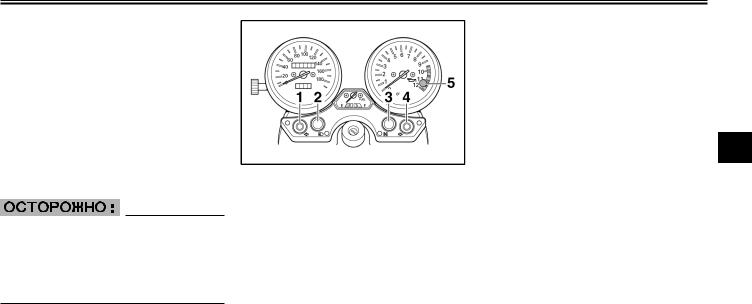
ФУНКЦИИ ПРИБОРОВ И ОРГАНОВ УПРАВЛЕНИЯ
EAU04356
“.“ (Парковка)
Руль заперт, задний и передний габаритные фонари горят, и аварийную сигнализацию можно включить, но все остальный электрические системы выклю- чены. Ключ можно вынуть.
Руль необходимо запереть перед тем, как установить ключ в положение “.“.
ECA00043
Не используйте положение“СТОЯНКА” в течение длительного времени, т. к. это может вызвать разрядку аккумуляторной батареи.
1.Индикатор левого поворота “4“
2.Индикатор дальнего света фары “&“
3.Индикатор нейтрали “N”
4.Индикатор правого поворота “6“
5.Предупредительная лампа уровня масла “7“
EAU03034
Индикатор и сигнальные лампы
EAU04121
Сигнальные лампы “4“ и “6“ указателя поворотов
При переводе переключателя указателя поворотов вправо или влево соответствующая сигнальная лампа начинает мигать.
EAU00063
Сигнальная лампа дальнего света “&“
Эта лампа горит, когда в фаре включена лампа дальнего света.
EAU00061
Сигнальная лампа нейтрали “N”
Когда коробка передач находится в нейтрали, эта сигнальная лампа горит.
EAU03201
Предупреждающий световой сигнал уровня масла “7“
Эта предупреждающая лампа го- 3 рит, когда уровень масла в двигателе слишком низкий. Электрические цепи этой лампы можно проверить следующим образом:
1.Установите переключатель остановки двигателя в положение “#“ и переведите ключ
в положение “ON” (“ВКЛЮЧЕ- НО”).
2.Установите коробку передач на нейтраль или нажмите на рычаг сцепления.
3.Нажмите на выключатель стартера. Если при нажатии на выключатель стартера сигнальная лампа не загорается, обращайтесь к дилеру фирмы Ямаха по поводу про-
верки электрических цепей.
3-2
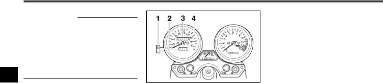
ФУНКЦИИ ПРИБОРОВ И ОРГАНОВ УПРАВЛЕНИЯ
ПРИМЕЧАНИЕ :
Даже если уровень масла достаточный, предупреждающая лампа может мерцать при езде по склону или при резких ускорениях или замедлениях, но это не свидетельствует о неисправно-
3 ñòè.
формация поможет Вам планировать будущие остановки для заправки.
1.Ручка сброса счетчика дальности поездки
2.Счетчик дальности поездки
3.Одометр
4.Спидометр
EAU00097
Узел спидометра
Узел спидометра содержит спидометр, одометр и счетчик дальности поездки. Спидометр
показывает скорость движения. Одометр показывает общий пробег мотоцикла. Счетчик дальности поездки показывает расстояние, пройденное с момента последнего сброса на нуль при помощи ручки сброса. Счетчик дальности в сочетании с указателем уровня топлива можно использовать для оценки расстоя-
ния, которое можно проехать с полным баком топлива. Эта ин-
3-3
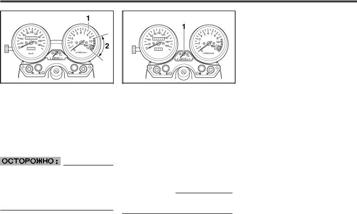
ФУНКЦИИ ПРИБОРОВ И ОРГАНОВ УПРАВЛЕНИЯ
1.Тахометр
2.Красный сектор тахометра
EAU00101
Тахометр
Электрический тахометр позволяет водителю контролировать частоту вращения двигателя и поддерживать оптимальный уровень мощности.
EC000003
Не позволяйте двигателю работать с оборотами, указанными в красном секторе тахометра.
Красный сектор : 9.500 об/мин и выше.
1. Указатель уровня топлива
EAU00110
Указатель уровня топлива
Указатель уровня топлива показывает количество топлива в баке. По мере понижения уровня топлива стрелка перемещается в сторону буквы “Е” (“Пус-
той”). Когда стрелка доходит до буквы “Е”, в баке остается примерно 4,5 литра топлива. В такой ситуации долейте топливо как можно скорее.
ПРИМЕЧАНИЕ :
Не допускайте полного опорожнения топливного бака.
|
EAU00109 |
||
|
Противоугонная сигнализа- |
||
|
ция (дополнительная) |
||
|
Этот мотоцикл можно оборудо- |
||
|
вать дополнительной противо- |
||
|
угонной сигнализацией у диле- |
||
|
ра фирмы “Ямаха”. Дополнитель- |
||
|
ную информацию можно полу- |
||
|
3 |
||
|
чить у дилера фирмы “Ямаха”. |
||
3-4
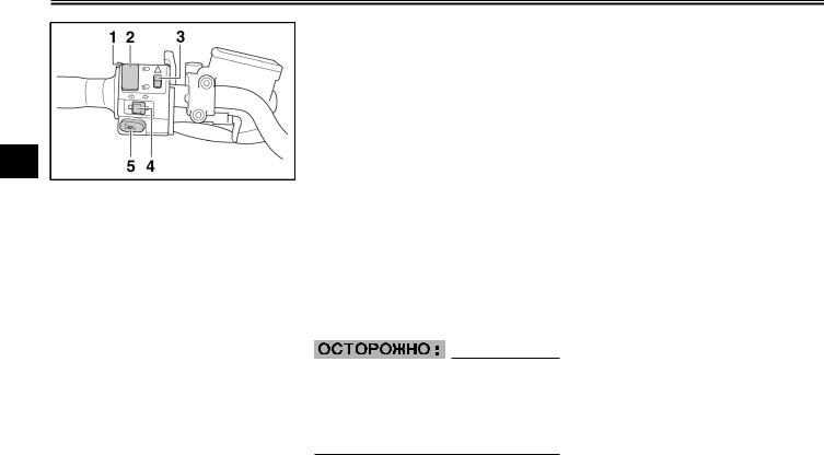
ФУНКЦИИ ПРИБОРОВ И ОРГАНОВ УПРАВЛЕНИЯ
3
1.Выключатель “PASS” (“ОБГОН”)
2.Переключатель света фары “&/ %“
3.Выключатель аварийной сигнализации “0“
4.Переключатель указателя поворотов “4/
6“
5.Выключатель звукового сигнала “*“
EAU00118
Выключатели на рукоятках
EAU00120
Выключатель “PASS” (“ОБГОН”)
Нажмите на этот выключатель для кратковременного включе- ния света фары.
EAU03888
Переключатель света фары “&/
%“
Установите этот переключа- тель в положение “&“ для включения дальнего света и в положение “% “ для включения ближнего света.
EAU03826
Выключатель аварийной сигнализации “0“
Когда ключ находится в положении “ON” (“ВКЛЮЧЕНО”) или в положении “Р” (“СТОЯНКА”) используйте этот выключатель для включения аварийной сигнализации (одновременного мигания всех указателей поворотов).
Аварийная сигнализация используется в аварийных ситуациях или для предупреждения других водителей в случае остановки мотоцикла в местах, где он может создавать помеху для движения.
EC000006
Не используйте аварийную сигнализацию в течение длительного времени, т. к. это может вызвать разрядку аккумуляторной батареи.
EAU03889
Переключатель указателя поворотов “4/6“
Для индикации правого поворота переведите переключатель в положение “6“. Для индикации левого поворота переведите переключатель в положение “4“. При отпускании переключатель возвращается в центральное положение. Для отмены подачи сигнала поворота нажмите на переключатель после того, как он вернется в центральное положение.
EAU00129
Выключатель звукового сигнала “*“
Нажмите на этот выключатель для подачи звукового сигнала.
3-5
![]()
ФУНКЦИИ ПРИБОРОВ И ОРГАНОВ УПРАВЛЕНИЯ
1.Выключатель остановки двигателя “#/$“
2.Переключатель световых приборов“:/ /
/
8“
3.Выключатель стартера “,“
EAU03890
Выключатель остановки двигателя “#/$“
Перед запуском двигателя установите этот выключатель в по-
ложение “#“. Устанавливайте этот выключатель в положение “$“ в аварийных ситуациях, например, при опрокидывании мотоцикла или при заедании троса дроссельной заслонки.
EAU03898
Переключатель световых приборов “:/ /8“
/8“
Устанавливайте этот переклю- чатель в положение “ “ для включения дополнительного фонаря, освещения приборов и
заднего габаритного фонаря. Устанавливайте переключатель в положение “:“ для того, чтобы включить также и свет фары. Устанавливайте переключатель в положение “8“ для того, чтобы выключить все осветительные приборы.
EAU00143
Выключатель стартера “,“
Нажмите на этот выключатель для проворачивания коленчатого вала двигателя стартером.
EC000005
Прочитайте инструкции по запуску на стр. 5-1 прежде, чем запускать двигатель.
3
1. Рычаг сцепления
EAU00153
Рычаг сцепления
Рычаг сцепления расположен на левой рукоятке руля. Для того, чтобы выключить сцепление, прижмите рычаг к рукоятке. Для того, чтобы включить сцепле-
ние, отпустите рычаг. Для обеспечения плавной работы сцепления прижимать рычаг следует быстро, а отпускать его медленно.
3-6

ФУНКЦИИ ПРИБОРОВ И ОРГАНОВ УПРАВЛЕНИЯ
3
1.Шкала регулировки положения рычага сцепления
2.Значок стрелки
Рычаг сцепления оборудован шкалой регулировки его положения. Для того, чтобы отрегулировать положение рычага сцеп-
ления, вращайте шкалу регулировки, оттягивая рычаг от рукоятки. Следите за тем, чтобы соответствующее обозначение было совмещено со значком стрелки на рычаге сцепления.
Рычаг сцепления оборудован выключателем, который является частью системы блокировки зажигания. (Описание системы блокировки зажигания приведено на стр. 3-19.)
1. Педаль переключателя передач
EAU00157
Педаль переключателя передач
Педаль переключателя передач расположена с левой стороны двигателя и используется в со- четании с рычагом сцепления
для переключения 6-ступенча- той коробки передач с шестернями постоянного зацепления, используемой на этом мотоцикле.
3-7
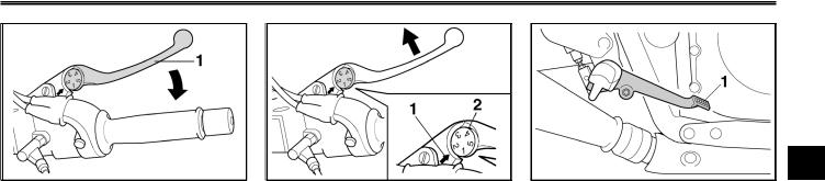
ФУНКЦИИ ПРИБОРОВ И ОРГАНОВ УПРАВЛЕНИЯ
1. Рычаг тормоза
EAU00161
Рычаг тормоза
Рычаг тормоза расположен на правой рукоятке руля. Для вклю- чения переднего тормоза прижмите рычаг тормоза к рукоятке.
1.Значок стрелки
2.Шкала регулировки положения рычага тормоза
Рычаг тормоза оборудован шкалой регулировки положения. Для того, чтобы отрегулировать расстояние между рычагом тормоза и рукояткой руля, оттягивая
рычаг от рукоятки, вращайте
шкалу регулировки. Следите за тем, чтобы соответствующая по-
зиция регулировочной шкалы
находилась напротив значка
стрелки на рычаге тормоза.
3
1. Педаль тормоза
EAU00162
Педаль тормоза
Педаль тормоза расположена на правой стороне мотоцикла. Для того, чтобы включить задний тормоз нажмите на педаль тормоза.
3-8
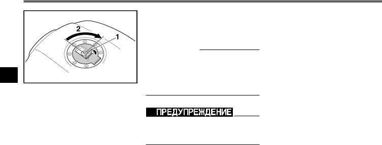
ФУНКЦИИ ПРИБОРОВ И ОРГАНОВ УПРАВЛЕНИЯ
3
1.Флажок замка крышки топливного бака
2.Отпирание
EAU02935
Крышка топливного бака
Как открыть крышку топливного бака
Откиньте флажок замка крышки топливного бака, вставьте ключ в замок и поверните ключ по ча- совой стрелке на 1/4 оборота. Замок отпирается и крышку топливного бака можно открыть.
Как закрыть крышку топливного бака
1.Установите крышку топливного бака на место, вставив ключ в ее замок.
2.Поверните ключ против часовой стрелки в его исходное положение, после чего опустите флажок замка.
ПРИМЕЧАНИЕ :
Крышку топливного бака нельзя закрыть, не вставив ключ в ее замок. Кроме того, ключ нельзя вынуть, если крышка не закрыта полностью и не заперта.
EWA00025
Перед каждой поездкой проверяйте, надежно ли закрыта крышка топливного бака.
3-9
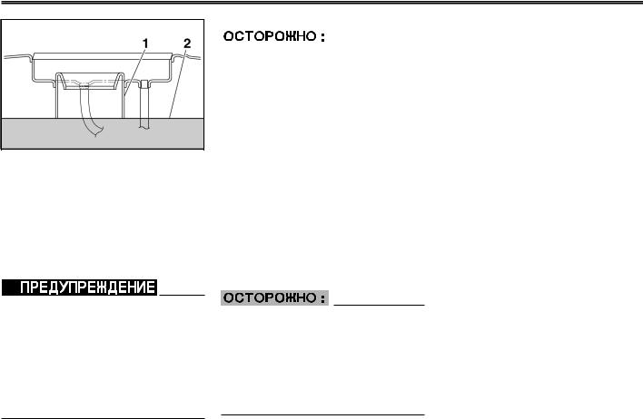
ФУНКЦИИ ПРИБОРОВ И ОРГАНОВ УПРАВЛЕНИЯ
1.Наливная горловина топливного бака
2.Уровень топлива
EAU03753
Топливо
Проверьте, достаточное ли количество топлива в баке. Заполняйте топливный бак до нижней кромки наливной горловины, как показано на рисунке.
EW000130
8Не допускайте переполнения топливного бака, иначе топливо может начать выливаться при расширении в результате нагрева.
8Не допускайте попадания топлива на горячий двигатель.
|
EAU00185 |
Конструкция двигателя Вашего |
|||||
|
мотоцикла “Ямаха” рассчитана |
||||||
|
Немедленно вытирайте проли- |
на использование обычного не- |
|||||
|
тое топливо чистой сухой мяг- |
этилированного бензина с ис- |
|||||
|
кой тканью, поскольку топливо |
следовательским октановым |
|||||
|
может повредить окрашенные |
числом не ниже 91. Если возни- |
|||||
|
поверхности или пластмассовые |
кает детонация (или металли- |
|||||
|
детали. |
ческие стуки), испольуйте бен- |
|||||
|
3 |
||||||
|
зин другой марки или высокока- |
||||||
|
EAU04284 |
||||||
|
чественное неэтилированное |
||||||
|
Рекомендуемое топливо |
||||||
|
топливо. Использование неэти- |
||||||
|
ТОЛЬКО ОБЫЧНЫЙ НЕЭТИ- |
||||||
|
лированного топлива увеличива- |
||||||
|
ЛИРОВАННЫЙ БЕНЗИН |
||||||
|
ет срок службы свечей зажига- |
||||||
|
Емкость топливного бака : |
||||||
|
ния и снижает расходы на техни- |
||||||
|
Общее количество : |
||||||
|
ческое обслуживание. |
||||||
|
21,0 литров |
||||||
|
Резервное количество : |
||||||
|
4,5 литра |
||||||
ECA00104
Используйте только неэтилированный бензин. Использование этилированного бензина ведет к серьезным повреждениям таких деталей двигателя, как клапаны и поршневые кольца, а также выпускной системы мотоцикла.
3-10
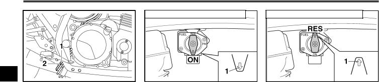
ФУНКЦИИ ПРИБОРОВ И ОРГАНОВ УПРАВЛЕНИЯ
3
1.Шланг сапуна топливного бака
2.Исходное положение (белая метка)
EAU02955
Шланг сапуна топливного бака
Перед поездкой на мотоцикле: 8 Проверьте соединения
шланга сапуна топливного
áàêà.
8Проверьте, нет ли на шланге сапуна трещин и повреждений, и замените его, если он поврежден.
8Проверьте, не засорен ли конец шланга, и очистьте его, если необходимо.
|
ON: Нормальное положение |
RES: Резервное положение |
1.Значок стрелки показывает на положение “ON” (“ОТКРЫТ”).
EAU00207
Топливный краник
Топливный краник служит для подачи топлива в карбюраторы, а также для фильтрации топлива.
Положения рычажка топливного краника показано на рисунках, а их описания приведены ниже.
ON
При установке рычажка краника
âэто положение топливо поступает в карбюратор, когда работает двигатель. При запуске двигателя и при езде устанавливайте рычажок топливного краника
âэто положение.
3-11
1.Значок стрелки показывает на положение “RES” (“РЕЗЕРВ”).
RES
Это обозначает “Резерв”. При установке рычажка топливного краника в это положение можно использовать резервный запас топлива. Если во время движе-
ния закончилось топливо, быстро переведите рычажок топливного краника в это положение, иначе двигатель может заглохнуть и придется заполнять карбюратор топливом (см. раздел “PRI” (“ЗАЛИВКА”)). После перевода краника в положение “RES” (“РЕЗЕРВ”), заправьте мотоцикл как можно скорее и не забудьте
перевести рычажок краника обратно в положение “ON” (“ОТКРЫТ”) !

ФУНКЦИИ ПРИБОРОВ И ОРГАНОВ УПРАВЛЕНИЯ
PRI Положение заливки 
1.Значок стрелки показывает на положение “PRI” (“ЗАЛИВКА”).
PRI
Это обозначает “Заливка”. При установке рычажка топливного краника в это положение происходит “заливка” бензина в двигатель. Если двигатель израсхо-
довал весь запас топлива, переведите рычажок топливного краника в это положение. При этом топливо поступает непосредственно в карбюратор, что облег- чает запуск. После запуска двигателя обязательно переведите рычажок топливного краника в положение “ON” (“ОТКРЫТ”) (или в положение “RES” (“РЕЗЕРВ”), если Вы еще не заправили мотоцикл).
1.Рычажок пускового устройства (воздушной заслонки) “ “
“
EAU03839
Рычажок пускового устройства (воздушной заслонки) “

 “
“
Для запуска холодного двигателя требуется более богатая воз- душно-топливная смесь, что
обеспечивается пусковым устройством (воздушной заслонкой).
Переведите рычажок в положение aдля использования пускового устройства (воздушной заслонки).
Переведите рычажок в положение b для возврата пускового устройства (воздушной заслонки) в исходное положение.
3
1. Отпирание
EAU04406
Сиденье
Как снять сиденье
1.Вставьте ключ в замок сиденья и поверните его, как показано на рисунке.
2.Снимите сиденье.
3-12
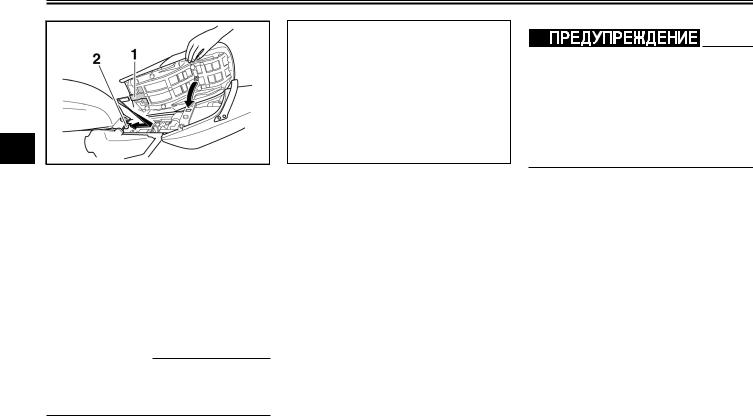
ФУНКЦИИ ПРИБОРОВ И ОРГАНОВ УПРАВЛЕНИЯ
3
1.Выступ
2.Держатель сиденья
Как установить сиденье
1.Вставьте выступ на передней части сиденья в держатель сиденья, как показано на рисунке.
2.Нажмите на заднюю часть сиденья до фиксации.
3.Выньте ключ.
ПРИМЕЧАНИЕ :
Проверяйте перед каждой поездкой, надежно ли закреплено сиденье.
1. Отпирание
EAU04291
Держатель шлема
Для того, чтобы открыть держатель шлема, вставьте ключ в замок сиденья и поверните его, как показано на рисунке.
Для того, чтобы запереть держатель шлема, поверните ключ в исходное положение и выньте его.
EW000030
Никогда не ездите на мотоцикле со шлемом, закрепленном на держателе, поскольку шлем может зацепиться за какое-нибудь препятствие, что ведет к потере управления, а возможно и к не- счастному случаю.
3-13

ФУНКЦИИ ПРИБОРОВ И ОРГАНОВ УПРАВЛЕНИЯ
1.Запорная скоба U-LOCK
2.Ремешок (2 шт.)
3.Замок запорной скобы U-LOCK
EAU04292
Багажный отсек
В этом багажном отсеке предусмотрено крепление для оригинальной запорной скобы U-LOCK
фирмы “Ямаха”. (Другие замки могут не подходить.) Укладывая запорную скобу U-LOCK в багажный отсек, надежно закрепляйте ее ремешками. Когда скоба не находится в багажнм отсеке, обязательно застегивайте ремешки, чтобы не потерять их.
При хранении “Руководства для владельца” и других документов в багажном отсеке обязательно укладывайте их в пластиковый пакет, чтобы они не намокли. При мытье мотоцикла следите за тем, чтобы вода не попадала в багажный отсек.
EAU00285
Регулировка передней вилки
Эта вилка оборудована болтами регулировки предварительного натяга пружин.
EW000035
Всегда устанавливайте одинаковый натяг обеих пружин, в против- 3 ном случае может ухудшиться управляемость мотоцикла и нарушиться его устойчивость.
3-14
ФУНКЦИИ ПРИБОРОВ И ОРГАНОВ УПРАВЛЕНИЯ
3
1.Болт регулировки предварительного натяга пружины
Отрегулируйте предварительный натяг пружин следующим образом:
Для того, чтобы увеличить предварительный натяг пружин и та-
ким образом увеличить жесткость подвески, поворачивайте болты на обеих стойках вилки в направлении a. Для уменьшения предварительного натяга пружин, а значит и для уменьшения жесткости подвески, поворачи- вайте болты на обеих стойках вилки в направлении b.
1.Текущее положение
2.Болт колпака передней вилки
ПРИМЕЧАНИЕ :
Совмещайте соответствующую канавку на механизме ргулировки с верхней плоскостью болта колпака передней вилки.
|
Установка |
|
|
Минимальная |
7 |
|
(мягкая) |
|
|
Стандартная |
5 |
|
Максимальная |
1 |
|
(жесткая) |
3-15
![]()
ФУНКЦИИ ПРИБОРОВ И ОРГАНОВ УПРАВЛЕНИЯ
EAU04407
Регулировка амортизаторов
Каждый из амортизаторов оборудован кольцом регулировки предварительного натяга пружины.
EC000015
Ни в коем случае не поворачивайте регулировочный механизм за пределы максимальной или минимальной установки.
EW000040
Оба амортизатора должны быть отрегулированы одинаково, в
противном случае возможно нарушение управляемости и потеря устойчивости мотоцикла.
1.Верхнее кольцо
2.Нижнее кольцо (кольцо регулировки предварительного натяга пружины)
При помощи специальных клю- чей, входящих в комплект инструментов владельца, отрегулируйте предварительный натяг пружин следующим образом:
Для того, чтобы увеличить предварительный натяг пружины и, следовательно, сделать подвеску более жесткой, удерживайте верхнее кольцо на месте и вращайте нижнее кольцо (регулировочное) на обоих амортизаторах в направлении, показанном на рисунке a.
3
1.Верхнее кольцо
2.Нижнее кольцо (кольцо регулировки предварительного натяга пружины)
Для того, чтобы уменьшить предварительный натяг пружины и, следовательно, сделать подвеску более мягкой, удерживайте верхнее кольцо на месте и вращайте нижнее кольцо (регулировочное) на обоих амортизаторах в направлении, показанном на рисунке b.
3-16

ФУНКЦИИ ПРИБОРОВ И ОРГАНОВ УПРАВЛЕНИЯ
Установка
|
Минимальный (мяг- |
Средний |
Максимальный |
|
|
кая) / Стандартный |
(жесткая) |
||
3
EAU00316
В этих амортизаторах находится газообразный азот под очень высоким давлением. Для того, чтобы правильно обращаться с ними, прочитайте и усвойте следующую информацию. Фирма-из- готовитель не несет ответственности за повреждение имущества или за травмы людей, которые могут произойти в результате неправильного обращения.
8Не переделывайте и не пытайтесь открывать газовые баллоны.
8Не подвергайте амортизаторы воздействию открытого пламени или других источ- ников тепла, поскольку в результате теплового расширения газа они могут взорваться.
8Не допускайте никаких деформаций или повреждений газовых баллонов, поскольку это снижает эффектив-
ность демпфирования.
8Всегда поручайте техниче- ское обслуживание амортизаторов дилеру фирмы “Ямаха”.
3-17

ФУНКЦИИ ПРИБОРОВ И ОРГАНОВ УПРАВЛЕНИЯ
1. Держатель багажного ремня (4 шт.)
EAU04276
Держатели багажного ремня
Имеется четыре держателя для багажных ремней, два из которых можно развернуть наружу для облегчения доступа.
EAU00330
Боковая подставка
Боковая подставка расположена на левой стороне рамы. Поднимайте боковую подставку или опускайте ее ногой, удерживая мотоцикл в вертикальном положении.
ПРИМЕЧАНИЕ :
Установленный на подножке выключатель является частью системы блокировки зажигания, который выключает зажигание в некоторых ситуациях. (Описание работы системы блокировки цепей зажигания приведено ниже.)
EW000044
На мотоцикле нельзя ездить с опущенной или с не полностью поднятой боковой подставкой (если она не фиксируется в поднятом положении), в противном случае подставка может касаться земли, что отвлекает водите- 3 ля и может вести к потере управления. Система блокировки зажигания фирмы Ямаха предназначена для облегчения водителю выполнения его обязанности поднимать боковую подставку перед началом движения. Поэтому регулярно проверяйте эту систему, как указано ниже, и обращайтесь к дилеру фирмы Ямаха по поводу ее ремонта, если она не работает должным образом.
3-18

ФУНКЦИИ ПРИБОРОВ И ОРГАНОВ УПРАВЛЕНИЯ
EAU03741
Система блокировки зажигания
Система блокировки зажигания (в которую входят выключатель на боковой подставке, выключа- тель на сцеплении и выключа- тель на нейтрали) выполняет
3 следующие функции :
8Она предотвращает запуск двигателя при включенной передаче и поднятой боковой подставке, но с отпущенным рычагом сцепления.
8Она предотвращает запуск двигателя при включенной передаче и нажатом рычаге
сцепления, но с опущенной боковой подставкой.
8Она вызывает остановку двигателя, когда при вклю- ченной передаче боковая подставка опускается.
Периодически проверяйте работу системы блокировки зажигания, выполняя указанные ниже операции.
EW000046
8При проведении этой проверки мотоцикл должен быть установлен на центральную подставку.
8При обнаружении любых неисправностей обращайтесь к дилеру фирмы Ямаха по поводу проверки этой системы прежде, чем продолжить эксплуатацию мотоцикла.
3-19
 Loading…
Мотоциклы Yamaha XJR1300 2003 — инструкция пользователя по применению, эксплуатации и установке на русском языке. Мы надеемся, она поможет вам решить возникшие у вас вопросы при эксплуатации техники.
Вы можете скачать инструкцию к Yamaha XJR1300 2003 по ссылке ниже, если не хотите ждать загрузки. Если остались вопросы, задайте их в комментариях после инструкции.
«Загружаем инструкцию», означает, что нужно подождать пока файл загрузится и можно будет его читать онлайн. Некоторые инструкции очень большие и время их появления зависит от вашей скорости интернета.
Полезные видео
Остались вопросы?
Не нашли свой ответ в руководстве или возникли другие проблемы? Задайте свой вопрос в форме ниже с подробным описанием вашей ситуации, чтобы другие люди и специалисты смогли дать на него ответ. Если вы знаете как решить проблему другого человека, пожалуйста, подскажите ему


Часто задаваемые вопросы

Как посмотреть инструкцию к Yamaha XJR1300 2003?
Необходимо подождать полной загрузки инструкции в сером окне на данной странице или скачать кликнув по специальной кнопке.
Руководство на русском языке?
Все наши руководства представлены на русском языке или схематично, поэтому вы без труда сможете разобраться с вашей моделью
Как можно распечатать инструкцию?
Скачайте ее по специальной кнопке над формой чтения на ваше устройства и отправьте на печать.