- Manuals
- Brands
- YAMAHA Manuals
- Scooter
- MAJESTY YP250
Manuals and User Guides for YAMAHA MAJESTY YP250. We have 5 YAMAHA MAJESTY YP250 manuals available for free PDF download: Service Manual, Owner’s Manual

YAMAHA MAJESTY YP250 Service Manual (267 pages)
Motorcycle YP250 4UC-AE1
Brand: YAMAHA
|
Category: Scooter
|
Size: 5.42 MB
Table of Contents
-
Table of Contents
9
-
How to Use this Manual
5
-
Periodic Inspection and
6
-
Chapter 1 General Information Scooter Identification
11
-
Engine Serial Number
11
-
Frame Serial Number
11
-
Model Label
11
-
VEHICLE IDENTIFICATION NUMBER (for E)
11
-
Features
12
-
Oil Indicator Light
12
-
Auto Choke System
13
-
Ignition Circuit Cut-Off System
13
-
-
Important Information
14
-
Preparation for Removal Procedures
14
-
Replacement Parts
14
-
Gaskets, Oil Seals and O-Rings
14
-
Lock Washers/Plates and Cotter Pins
15
-
Bearings and Oil Seals
15
-
Circlips
15
-
Checking of Connections
16
-
How to Use the Conversion Table
17
-
-
Special Tools
18
-
-
Table of Contents
21
-
Chapter 2. Specifications
23
-
General Specifications
23
-
Maintenance Specifications
26
-
Engine
26
-
Chassis
32
-
Electrical
36
-
-
General Torque Specifications
38
-
Lubrication Point and Grade of Lubricant
39
-
Engine
39
-
Chassis
40
-
-
Cable Routing
41
-
-
Table of Contents
49
-
Chapter 3
51
-
Introduction
51
-
Periodic Inspection and Adjustment
51
-
Periodic Maintenance/Lubrication Intervals
51
-
Cover and Panel
53
-
Side Panel and Seat
53
-
Tail Cover and Fuel Tank
54
-
Footrest Board and Lower Cover
56
-
Cowling
57
-
Handle Cover, Meter Assembly and Legshield
58
-
-
Engine
59
-
Valve Clearance Adjustment
59
-
Idling Speed Adjustment
60
-
Throttle Cable Adjustment
61
-
Spark Plug Inspection
62
-
Ignition Timing Check
63
-
Compression Pressure Measurement
64
-
Engine Oil Level Inspection
65
-
Recommended Engine Oil
66
-
Engine Oil Replacement
66
-
Engine Oil Pressure Inspection
67
-
Transmission Oil Replacement
68
-
Exhaust System Inspection
69
-
Air Filter Cleaning
69
-
Crankcase Filter Cleaning
70
-
Coolant Level Inspection
71
-
Coolant Replacement
72
-
Cooling System Inspection
75
-
-
Chassis
76
-
Front Brake Adjustment
76
-
Brake Fluid Level Inspection
77
-
Brake Pad Inspection
78
-
Air Bleeding (Hydraulic Brake System)
78
-
Rear Brake Adjustment
79
-
Brake Shoe Inspection
80
-
Steering Head Inspection
80
-
Front Fork Inspection
82
-
Swingarm Inspection
83
-
Rear Shock Absorber Inspection
83
-
Rear Shock Absorber Adjustment
83
-
Tire Inspection
84
-
Wheel Inspection
86
-
-
Electrical
87
-
Battery Inspection
87
-
Fuse Inspection
92
-
Headlight Beam Adjustment
93
-
-
-
Insp Adj
95
-
Chapter 4. Engine
97
-
Engine Overhaul
97
-
Wireharness and Cable
97
-
Hoses, Air Filter Case, Engine Mounting Bolt and Engine
99
-
Engine Remounting
100
-
-
Cylinder Head
101
-
Cylinder Head Removal
103
-
Cylinder Head Inspection
103
-
Cylinder Head Installation
104
-
-
Camshaft and Rocker Arms
107
-
Camshaft Inspection
108
-
Camshaft and Rocker Arm Installation
109
-
-
Valves and Valve Springs
111
-
Valves and Valve Springs Removal
112
-
Valves and Valve Springs Inspection
112
-
Valve Seat Inspection
114
-
Valves and Valve Springs Installation
115
-
-
Cylinder and Piston
117
-
Piston and Pistonrings Removal
118
-
Cylinder Inspection
118
-
Piston and Piston Pin Inspection
119
-
Piston Rings Inspection
120
-
Piston Rings, Piston and Cylinder Installation
121
-
Crankcase Filter Cover and Crankcase Cover (Left)
123
-
Secondary Sheave
126
-
Primary Sheave Removal
127
-
Secondary Sheave and V Belt Removal
127
-
Secondary Sheave Disassembly
128
-
Clutch Inspection
128
-
Belt Inspection
129
-
Weight Inspection
129
-
Secondary Sheave Inspection
129
-
Primary Sheave Assembly
130
-
Secondary Sheave Installation
130
-
-
A.C. Magneto and Starter Clutch
133
-
Magneto Cover and Stator Coil
133
-
Magneto and Starter Clutch
135
-
Starter Drive Gear Inspection
136
-
-
Oil Pump
138
-
Oil Pump Inspection
139
-
-
Transmission
140
-
Crankcase and Crankshaft
142
-
Crankshaft Removal
144
-
Crankshaft Inspection
144
-
-
-
Table of Contents
147
-
Chapter 5
149
-
Cooling System Radiator
149
-
Inspection
150
-
Water Pump
151
-
Inspection
153
-
Water Pump Installation
153
-
-
Thermostat
155
-
Inspection
156
-
Installation
156
-
-
-
Table of Contents
157
-
Carburetion
159
-
Carburetor Disassembly
160
-
Chapter 6
160
-
Assembly
162
-
Fuel Level Adjustment
163
-
Auto Choke Inspection
164
-
Fuel Pump Inspection
165
-
-
Table of Contents
167
-
Chapter 7. Chassis
169
-
Front Wheel and Brake Disc
169
-
Front Wheel Disassembly
170
-
Front Wheel Disassembly
171
-
Front Wheel Inspection
171
-
Brake Disc Inspection
172
-
Front Wheel Assembly
172
-
Front Wheel Installation
173
-
Wheel Static Balance Adjustment
174
-
-
Rear Wheel and Rear Brake
176
-
Rear Wheel Inspection
178
-
Rear Brake Inspection
178
-
Rear Brake Installation
179
-
-
Front Brake
180
-
Brake Pad
180
-
Brake Pad Replacement
181
-
Master Cylinder
182
-
Master Cylinder Disassembly
183
-
Master Cylinder Inspection
184
-
Master Cylinder Assembly
184
-
Caliper
187
-
Caliper Disassembly
188
-
Brake Caliper Disassembly
189
-
Caliper Inspection
189
-
Brake Caliper Assembly
190
-
-
Front Fork
191
-
Front Fork Disassembly
192
-
Front Fork Removal
193
-
Front Fork Disassembly
193
-
Front Fork Inspection
194
-
Front Fork Assembly
194
-
Front Fork Installation
197
-
-
Handlebar
198
-
Handlebar Removal
200
-
Handlebar Inspection
200
-
Handlebar Installation
200
-
-
Steering
202
-
Steering Removal
204
-
Inspection
204
-
Steering Installation
205
-
-
Rear Shock Absorber and Swingarm
206
-
-
Table of Contents
207
-
Chapter 8. Electrical Electrical Components
209
-
Circuit Diagram
210
-
Checking Switches
212
-
Checking Steps
212
-
Switch Connection as Shown in this Manual
212
-
Switch Position and Terminal Connection
213
-
-
Ignition System
214
-
Circuit Diagram
214
-
Troubleshooting
215
-
-
Charging System
219
-
Circuit Diagram
219
-
Troubleshooting
220
-
-
Electric Starting System
223
-
Circuit Diagram
223
-
Troubleshooting
224
-
Starter Motor
227
-
-
Lighting System
230
-
Circuit Diagram
230
-
Troubleshooting
231
-
-
Signal System
236
-
Circuit Diagram
236
-
Troubleshooting
237
-
Signal System Check
239
-
Checking of Connections
243
-
-
Cooling System
245
-
Circuit Diagram
245
-
Troubleshooting
246
-
Special Tools
246
-
-
Auto Choke System
252
-
Circuit Diagram
252
-
-
-
Troubleshooting
257
-
Chapter 9. Troubleshooting
259
-
Starting Failure/Hard Starting
259
-
Fuel System
259
-
Compression System
259
-
Ignition System
260
-
-
Poor Idle Speed Performance
260
-
Poor Medium and High Speed Performance
261
-
Poor Speed Performance
261
-
Poor Speed Performance
262
-
-
Faulty Clutch
262
-
When Engine Is Run, Scooter Does Not Run
262
-
Poor Starting Performance
262
-
-
Overheating or over Cooling
263
-
Overheating
263
-
Over Cooling
263
-
-
Faulty Brake
264
-
Poor Braking Effect
264
-
-
Front Fork Malfunction
264
-
Oil Leakage
264
-
Malfunction
264
-
-
Instable Handling
265
-
Starter Motor Does Not Operate
265
-
Faulty Signal and Lighting System
266
-
Headlight Dark
266
-
Bulb Burnt out
266
-
Flasher Does Not Blink
266
-
Flasher Keeps on
266
-
Flasher Blinks Slower
266
-
Flasher Blinks Quicker
266
-
Horn Does Not Sound
266
-
-
Advertisement
YAMAHA MAJESTY YP250 Owner’s Manual (114 pages)
Brand: YAMAHA
|
Category: Scooter
|
Size: 2.06 MB
Table of Contents
-
Table of Contents
6
-
Give Safety the Right of Way
8
-
Description
12
-
Left View
13
-
Right View
14
-
Controls and Instruments
15
-
-
-
Instrument and Control Functions
16
-
Instrument and Control Functions
17
-
Indicator Lights
18
-
Speedometer
19
-
Tachometer
19
-
Fuel Gauge
20
-
Coolant Temperature Gauge
21
-
Multi-Function Display
21
-
Anti-Theft Alarm (Optional)
25
-
Handlebar Switches
26
-
Front Brake Lever
28
-
Rear Brake Lever
29
-
Fuel Tank Cap
29
-
Fuel
30
-
Catalytic Converter
31
-
Rider Seat
32
-
Adjusting the Rider Seat
33
-
Storage Compartments
33
-
Adjusting the Shock Absorber Assemblies
35
-
Sidestand
36
-
Ignition Circuit Cut-Off System
37
-
-
Main Switch/Steering Lock
17
-
Pre-Operation Checks
40
-
Pre-Operation Check List
41
-
-
-
Operation and Important Riding Points
44
-
Operation and Important Riding Points
45
-
Starting the Engine
45
-
Starting off
46
-
Acceleration and Deceleration
47
-
Braking
47
-
Engine Break-In
48
-
Tips for Reducing Fuel Consumption
48
-
Parking
49
-
-
Periodic Maintenance and Minor Repair
50
-
Owner’s Tool Kit
51
-
Periodic Maintenance and Lubrication Chart
53
-
Removing and Installing the Cowlings and Panel
56
-
Checking the Spark Plug
62
-
Engine Oil
64
-
Final Transmission Oil
68
-
Coolant
69
-
Air Filter and V-Belt Case Air Filter Elements
71
-
Adjusting the Throttle Cable Free Play
73
-
Adjusting the Valve Clearance
73
-
Air Flow Louver
73
-
Tires
74
-
Cast Wheels
76
-
Adjusting the Front and Rear Brake Lever Free Play
77
-
Checking the Front and Rear Brake Pads
78
-
Checking the Brake Fluid Level
79
-
Changing the Brake Fluid
80
-
Checking and Lubricating the Cables
80
-
Checking and Lubricating the Centerstand and Sidestand
81
-
Checking and Lubricating the Throttle Grip and Cable
81
-
Lubricating the Front and Rear Brake Levers
81
-
Checking the Front Fork
82
-
Checking the Steering
83
-
Checking the Wheel Bearings
83
-
Battery
84
-
To Store the Battery
85
-
-
Removing the Battery Cover
84
-
Replacing the Fuses
86
-
Replacing a Headlight Bulb
87
-
Replacing a Front Turn Signal Light Bulb
89
-
Replacing a Rear Turn Signal Light Bulb
90
-
Replacing a Tail/Brake Light Bulb
90
-
Replacing the License Plate Light Bulb
91
-
Troubleshooting
92
-
Troubleshooting Charts
93
-
Scooter Care and Storage
96
-
Specifications
102
-
Specifications
103
-
Conversion Table
107
-
-
Consumer Information
108
-
Consumer Information
109
-
Identification Numbers
109
-
Key Identification Number
109
-
Vehicle Identification Number
109
-
Model Label
110
-
-

Yamaha MAJESTY YP250 Owner’s Manual (116 pages)
Brand: Yamaha
|
Category: Scooter
|
Size: 2.08 MB
Table of Contents
-
Table of Contents
7
-
Give Safety the Right of Way
9
-
Description
13
-
-
Instrument and Control Functions
17
-
Main Switch/Steering Lock
18
-
Indicator Lights
19
-
Speedometer
20
-
Tachometer
20
-
Fuel Gauge
21
-
Coolant Temperature Gauge
22
-
Multi-Function Display
22
-
Anti-Theft Alarm (Optional)
26
-
Handlebar Switches
27
-
Front Brake Lever
29
-
Fuel Tank Cap
30
-
Rear Brake Lever
30
-
Fuel
31
-
Catalytic Converter
32
-
Rider Seat
33
-
Adjusting the Rider Seat
34
-
Storage Compartments
34
-
Adjusting the Shock Absorber Assemblies
36
-
Sidestand
37
-
Ignition Circuit Cut-Off System
38
-
Pre-Operation Checks
41
-
-
Operation and Important Riding Points
45
-
Starting the Engine
46
-
Starting off
47
-
Acceleration and Deceleration
48
-
Braking
48
-
Engine Break-In
49
-
Tips for Reducing Fuel Consumption
49
-
Parking
50
-
-
Periodic Maintenance and Minor Repair
51
-
Owner’s Tool Kit
52
-
Periodic Maintenance and Lubrication Chart
54
-
Removing and Installing the Cowlings and Panel
57
-
Checking the Spark Plug
63
-
Engine Oil
65
-
Final Transmission Oil
69
-
Coolant
70
-
Air Filter and V-Belt Case Air Filter Elements
72
-
Adjusting the Throttle Cable Free Play
74
-
Adjusting the Valve Clearance
74
-
Air Flow Louver
74
-
Tires
75
-
Cast Wheels
77
-
Adjusting the Front and Rear Brake Lever Free Play
78
-
Checking the Front and Rear Brake Pads
79
-
Checking the Brake Fluid Level
80
-
Changing the Brake Fluid
81
-
Checking and Lubricating the Cables
81
-
Checking and Lubricating the Centerstand and Sidestand
82
-
Checking and Lubricating the Throttle Grip and Cable
82
-
Lubricating the Front and Rear Brake Levers
82
-
Checking the Front Fork
83
-
Checking the Steering
84
-
Checking the Wheel Bearings
84
-
Battery
85
-
To Store the Battery
86
-
-
Removing the Battery Cover
85
-
Replacing the Fuses
87
-
Replacing a Headlight Bulb
88
-
Replacing a Front Turn Signal Light Bulb
90
-
Replacing a Rear Turn Signal Light Bulb
91
-
Replacing a Tail/Brake Light Bulb
91
-
Replacing the License Plate Light Bulb
92
-
Troubleshooting
93
-
Troubleshooting Charts
94
-
Scooter Care and Storage
97
-
Specifications
103
-
Specifications
104
-
Conversion Table
108
-
-
Consumer Information
109
-
Advertisement
YAMAHA MAJESTY YP250 Owner’s Manual (98 pages)
Brand: YAMAHA
|
Category: Scooter
|
Size: 2.09 MB
Table of Contents
-
Table of Contents
7
-
Give Safety the Right of Way
9
-
Description
13
-
Description
16
-
-
Instrument and Control Functions
17
-
Main Switch/Steering Lock
18
-
Indicator Lights
19
-
Oil Change Indicator Light Circuit Check
20
-
Diagnosis Device
21
-
Speedometer
21
-
Antitheft Alarm (Optional)
22
-
Coolant Temperature Gauge
22
-
Fuel Gauge
22
-
Digital Clock
23
-
Handlebar Switches
23
-
Headlight Beam Variation
25
-
Front Brake Lever
26
-
Fuel Tank Cap
27
-
Rear Brake Lever
27
-
Fuel
28
-
Catalyzer
29
-
Rider Seat
29
-
Rider Seat Adjustment
30
-
Storage Compartments
31
-
Rear Shock Absorber Adjustment
32
-
Carrier (Optional)
33
-
Sidestand
33
-
Sidestand Switch Operation Check
34
-
Pre-Operation Checks
35
-
Pre-Operation Check List
36
-
-
-
Operation and Important Riding Points
37
-
Starting a Cold Engine
38
-
Acceleration
39
-
Braking
39
-
Starting off
39
-
Engine Break-In
40
-
Tips for Reducing Fuel Consumption
40
-
Parking
41
-
-
Periodic Maintenance and Minor Repair
43
-
Periodic Maintenance and Minor Repair
44
-
Tool Kit
44
-
Periodic Maintenance and Lubrication
46
-
Panel a
49
-
Panel Removal and Installation
49
-
Panel B
51
-
Panel C
51
-
Spark Plug
53
-
Engine Oil
54
-
Final Gear Oil Replacement
57
-
Coolant
58
-
Tires
61
-
Air Flow Louver
61
-
-
Brake Lever Free Play Adjustment
63
-
Wheels
63
-
Checking the Front and Rear Brake Pads
64
-
Inspecting the Brake Fluid Level
65
-
Brake Fluid Replacement
66
-
Brake Lever Lubrication
66
-
Cable Inspection and Lubrication
66
-
Center and Sidestand Lubrication
67
-
Front Fork Inspection
67
-
Steering Inspection
68
-
Wheel Bearings
68
-
Battery
69
-
Battery Cover Removal
69
-
Fuse Replacement
70
-
Battery Storage
70
-
-
Headlight Bulb Replacement
71
-
Front Turn Signal Light Bulb Replacement
73
-
Tail/Brake Light Bulb Replacement
73
-
Rear Turn Signal Light Bulb Replacement
74
-
License Light Bulb Replacement
75
-
Troubleshooting
76
-
Troubleshooting Chart
77
-
Engine Overheating
78
-
-
Scooter Care and Storage
79
-
Specifications
85
-
Specifications
86
-
How to Use the Conversion Table
90
-
-
Consumer Information
91
-
Consumer Information
92
-
Identification Number Records
92
-
Key Identification Number
92
-
Vehicle Identification Number
92
-
Model Label
93
-
-
Yamaha MAJESTY YP250 Owner’s Manual (106 pages)
Brand: Yamaha
|
Category: Motorcycle
|
Size: 1.73 MB
Table of Contents
-
Table of Contents
6
-
Give Safety the Right of Way
8
-
Description
12
-
-
Instrument and Control Functions
16
-
Main Switch/Steering Lock
17
-
Indicator Lights
18
-
Self-Diagnosis Device
19
-
Speedometer Unit
19
-
Anti-Theft Alarm (Optional)
20
-
Coolant Temperature Gauge
20
-
Fuel Gauge
20
-
Clock
21
-
Handlebar Switches
21
-
Front Brake Lever
24
-
Rear Brake Lever
24
-
Fuel Tank Cap
25
-
Catalytic Converter
26
-
Fuel
26
-
Rider Seat
27
-
Adjusting the Rider Seat
28
-
Storage Compartments
28
-
Adjusting the Shock Absorber Assemblies
30
-
Ignition Circuit Cut-Off System
31
-
Sidestand
31
-
Pre-Operation Checks
34
-
-
Operation and Important Riding Points
38
-
Starting the Engine
39
-
Starting off
40
-
Acceleration and Deceleration
41
-
Braking
41
-
Engine Break-In
42
-
Tips for Reducing Fuel Consumption
42
-
Parking
43
-
-
Periodic Maintenance and Minor Repair
44
-
Owner’s Tool Kit
45
-
Periodic Maintenance and Lubrication Chart
47
-
Removing and Installing Cowlings and Panel
50
-
Checking the Spark Plug
56
-
Engine Oil
58
-
Final Gear Oil
61
-
Coolant
62
-
Air Filter and V-Belt Case Air Filter Elements
64
-
Air Flow Louver
66
-
Tires
67
-
Adjusting the Front and Rear Brake Lever Free Play
69
-
Wheels
69
-
Checking the Front and Rear Brake Pads
70
-
Checking the Brake Fluid Level
71
-
Changing the Brake Fluid
72
-
Checking and Lubricating the Cables
72
-
Lubricating the Front and Rear Brake Levers
72
-
Checking and Lubricating the Centerstand and Sidestand
73
-
Checking the Front Fork
73
-
Checking the Steering
74
-
Battery
75
-
Checking the Wheel Bearings
75
-
Removing the Battery Cover
75
-
Replacing the Fuses
77
-
Replacing a Headlight Bulb
78
-
Replacing a Front Turn Signal Light Bulb
79
-
Replacing a Rear Turn Signal Light Bulb
80
-
Replacing a Tail/Brake Light Bulb
81
-
Replacing the License Plate Light Bulb
81
-
Troubleshooting
82
-
Troubleshooting Charts
83
-
Scooter Care and Storage
86
-
Specifications
92
-
Consumer Information
98
-
Advertisement
Related Products
-
YAMAHA XMAX YP250R
-
YAMAHA XMAX YP250RA
-
YAMAHA MAJESTY YP250A
-
Yamaha YP250R 2005
-
Yamaha MAJESTY YP250A ABS
-
Yamaha YP250 98
-
Yamaha YP250J 98
-
Yamaha YP250R 2014
-
Yamaha YP250RA 2014
-
YAMAHA YP125RA Business Edition
YAMAHA Categories
Motorcycle
Musical Instrument
Electronic Keyboard
Receiver
Amplifier
More YAMAHA Manuals
-
Contents
-
Table of Contents
-
Troubleshooting
-
Bookmarks
Quick Links
Chapters
-
Table of Contents
9 -
Table of Contents
21 -
Table of Contents
49 -
Insp Adj
95 -
Table of Contents
147 -
Table of Contents
157 -
Table of Contents
167 -
Table of Contents
207 -
Troubleshooting
257
Troubleshooting
-
TROUBLESHOOTING
215 -
TROUBLESHOOTING
220 -
TROUBLESHOOTING
224 -
TROUBLESHOOTING
231 -
TROUBLESHOOTING
237 -
TROUBLESHOOTING
246 -
TROUBLESHOOTING
257 -
CHAPTER 9. TROUBLESHOOTING
259
Related Manuals for Yamaha YP250
Summary of Contents for Yamaha YP250
-
Page 3
EB000000 YP250 SERVICE MANUAL 1996 by Yamaha Motor Co., Ltd. 1st Edition, January 1996 All rights reserved. Any reprinting or unauthorized use without the written permission of Yamaha Motor Co., Ltd. is expressly prohibited. -
Page 4
It is not possible to include all the knowledge of a mechanic in one manual, so it is assumed that anyone who uses this book to perform maintenance and repairs on Yamaha scooter has a basic understanding of the mechanical ideas and the procedures of scooter repair. Re- pairs attempted by anyone without this knowledge are likely to render the scooter unsafe and unfit for use. -
Page 5: How To Use This Manual
YP002000 HOW TO USE THIS MANUAL MANUAL ORGANIZATION This manual consists of chapters for the main categories of subjects. (See “Illustrated symbols”) 1st title 1 : This is the title of the chapter with its symbol on the upper right corner of each page. 2nd title 2 : This title indicates the section of the chapter and only appears on the first page of each section.
-
Page 6: Periodic Inspection And
EB003000 ILLUSTRATED SYMBOLS Illustrated symbols 1 to 9 are designed as thumb tabs to indicate the chapter’s number and content. 1 General information 2 Specifications 3 Periodic inspection and adjustment 4 Engine 5 Cooling system 6 Carburetion 7 Chassis 8 Electrical 9 Troubleshooting Illustrated symbols are used to identify…
-
Page 7
INDEX GENERAL INFORMATION INFO SPECIFICATIONS SPEC PERIODIC INSPECTION AND INSP ADJUSTMENT ENGINE OVERHAUL COOLING SYSTEM COOL CARBURETION CARB CHASSIS CHAS ELECTRICAL ELEC TROUBLESHOOTING TRBL SHTG… -
Page 9: Table Of Contents
CHAPTER 1 GENERAL INFORMATION SCOOTER IDENTIFICATION ……..VEHICLE IDENTIFICATION NUMBER (for E) .
-
Page 11: General Information Scooter Identification
SCOOTER IDENTIFICATION INFO YP100000 GENERAL INFORMATION SCOOTER IDENTIFICATION YP100010 VEHICLE IDENTIFICATION NUMBER (for E) The vehicle identification number 1 is stamped into the right side of the frame. NOTE: The vehicle identification number is used to identify your scooter and may be used to regis- ter your scooter with the licensing authority in your country.
-
Page 12: Features
FEATURES INFO FEATURES OIL INDICATOR LIGHT S Function Pulses (travel distance signals) from the speedometer are counted and cause the oil indicator light to come on at 1,000 km for the first time and thereafter every 3,000 km. In this way, this light indicates the time for oil change.
-
Page 13: Auto Choke System
FEATURES INFO AUTO-CHOKE SYSTEM This system is the parallel connection of the ignitor unit circuit and the thermo switch as shown, detect- ing the engine temperature, and facilitates the restarting with the warm engine. S Circuit diagram Igniter unit Main switch Thermo Fuse Ignition…
-
Page 14: Important Information
6. Keep all parts away from any source of fire. EB101010 REPLACEMENT PARTS 1. Use only genuine Yamaha parts for all re- placements. Use oil and grease recom- mended by Yamaha for all lubrication jobs. Other brands may be similar in function and appearance, but inferior in quality.
-
Page 15: Lock Washers/Plates And Cotter Pins
IMPORTANT INFORMATION INFO EB101030 LOCK WASHERS/PLATES AND COTTER PINS 1. Replace all lock washers/plates and cotter pins after removal. Bend lock tabs along the bolt or nut flats after the bolt or nut has been tightened to specification. EB101040 BEARINGS AND OIL SEALS Install bearings and oil seals so that the manufacturer’s marks or numbers are visible.
-
Page 16: Checking Of Connections
IMPORTANT INFORMATION INFO EB801000 CHECKING OF CONNECTIONS Dealing with stains, rust, moisture, etc. on the connector. 1. Disconnect: S Connector 2. Dry each terminal with an air blower. 3. Connect and disconnect the connector two or three. 4. Pull the lead to check that it will not come off.
-
Page 17: How To Use The Conversion Table
HOW TO USE THE CONVERSION TABLE INFO EB201000 HOW TO USE THE CONVERSION TABLE All specification data in this manual are listed in SI and METRIC UNITS. Use this table to convert METRIC unit data to IMPERIAL unit data. METRIC MULTIPLIER **mm 0.03937…
-
Page 18: Special Tools
SPECIAL TOOLS INFO EB102000 SPECIAL TOOLS The following special tools are necessary for complete and accurate tune-up and assembly. Use only the appropriate special tools; this will help prevent damage caused by the use of inappropri- ate tools or improvised techniques. When placing an order, refer to the list provided below to avoid any mistakes.
-
Page 19
SPECIAL TOOLS INFO Tool No. Tool name/Usage Illustration 90890-01362 Flywheel puller This tool is used for removing the rotor. 90890-01367 Fork seal driver weight -01368 Fork seal driver attachment (ø33) This tool is used when installing the fork seal. 90890-01384 Oil seal guide This tool is used for protecting the oil seal lip when installing the secondary… -
Page 20
Mechanical seal installer These tools are used for installing mechanical seal. 90890-06754 Ignition checker This instrument is necessary for checking the ignition system components. 90890-85505 Yamaha bond No. 1215 This sealant (bond) is used for crankcase mating surface, etc. 1-10… -
Page 21
CHAPTER 2. SPECIFICATIONS GENERAL SPECIFICATIONS ……..MAINTENANCE SPECIFICATIONS . -
Page 23: Chapter 2. Specifications
SPEC GENERAL SPECIFICATIONS SPECIFICATIONS GENERAL SPECIFICATIONS Model YP250 Model code: 4UC 1 (except for CH, A) 4UD1 (for CH, A) Dimensions: Overall length 2,110 mm Overall width ,750 mm Overall height 1,330 mm Seat height ,700 mm Wheelbase 1,500 mm…
-
Page 24
SPEC GENERAL SPECIFICATIONS Model YP250 Carburetor: Type/quantity Y28V-1A/1 Manufacturer TEIKEI Spark plug: Type DR8EA Manufacturer 0.6 X 0.7 mm Spark plug gap Clutch type: Dry, centrifugal automatic Transmission: Primary reduction system Helical gear Primary reduction ratio 40/15 (2.666) Secondary reduction sytem… -
Page 25
SPEC GENERAL SPECIFICATIONS Model YP250 Brake: Front brake type Single disc brake operation Right hand operation Rear brake type Drum brake operation Left hand operation Suspension: Front suspension Telescopic fork Rear suspension Unit swing Shock absorber: Front shock absorber Coil spring/Oil damper… -
Page 26: Maintenance Specifications
SPEC MAINTENANCE SPECIFICATIONS MAINTENANCE SPECIFICATIONS ENGINE Item Standard Limit Cylinder head: Warp limit 0.03 mm Cylinder: 69.000 X 69.005 mm Bore size 69.1 mm Out of round limit 0.03 mm Camshaft: Cam dimensions 36.545 X 36.645 mm Intake “A” 36.45 mm 30.021 X 30.121 mm “B”…
-
Page 27
SPEC MAINTENANCE SPECIFICATIONS Item Standard Limit 0.010 X 0.037 mm Stem-to-guide clearance 0.08 mm 0.025 X 0.052 mm 0.1 mm Stem runout limit 0.01 mm 0.9 X 1.1 mm Valve seat width 1.6 mm 0.9 X 1.1 mm 1.6 mm Valve spring: Free length (Inner) IN/EX… -
Page 28
SPEC MAINTENANCE SPECIFICATIONS Item Standard Limit Automatic centrifugal clutch: Clutch shoe thickness 3.0 mm 2.0 mm Clutch housing inside diameter 135 mm 135.5 mm Clutch shoe spring free length 28.1 mm Weight outside diameter 20 mm 19.5 mm 2,100 X 2,700 r/min Clutch –… -
Page 29
SPEC MAINTENANCE SPECIFICATIONS Item Standard Limit Radiator: Type Cooling fin with electric fan Width/height/thickness 140/238/24 mm 110 X 140 kPa (1.1 X 1.4 kg/cm Radiator cap opening pressure 1.1 X 1.4 bar) Radiator capacity 1.4 L Reservoir tank capacity 0.35 L Thermostatic valve: Type/manufacturer 4HC/NIHON THERMOSTAT… -
Page 30
SPEC MAINTENANCE SPECIFICATIONS TIGHTENING TORQUES ENGINE Tightening Thread torque Part to be tightened Part name Q’ty Remarks size size mSkg Oil check bolt — Exhaust pipe stud bolt — Spark plug — Cam sprocket cover Bolt Cylinder head and cylinder Cylinder head and cylinder Bolt (Cam chain side) -
Page 31
SPEC MAINTENANCE SPECIFICATIONS Tightening Thread torque Part to be tightened Part name Q’ty Remarks size size mSkg Cover (oil pump) Bolt Timing check plug Plug One way clutch — Clutch housing Bolt Grease stopper (Primary sheave) — Primary fixed sheave —… -
Page 32: Chassis
SPEC MAINTENANCE SPECIFICATIONS CHASSIS Item Standard Limit Steering system: Steering bearing type Ball bearing Front suspension: Front fork travel 100 mm Fork spring free length 265.8 mm 263.5 mm Spring rate (K1) 5.7 N/mm (0.57 kg/mm) 0 X 100 mm Stroke (K1) Oil capacity…
-
Page 33
SPEC MAINTENANCE SPECIFICATIONS Item Standard Limit Rear drum brake: Type Leading, trailing Drum inside diameter 160 mm 161 mm Shoe thickness 4 mm 2 mm Brake lever: 2 X 5 mm Brake lever free play (front at lever side) 10 X 20 mm Brake lever free play (rear) 3 X 5 mm Throttle cable free play… -
Page 34
SPEC MAINTENANCE SPECIFICATIONS TIGHTENING TORQUES CHASSIS Tightening torque Part to be tightened Thread size Remarks mSkg Frame and engine bracket 1.25 Engine bracket, compression rod and engine 1.25 Compression rod and frame 1.25 Sidestand (bolt and frame) 1.25 Sidestand (bolt and nut) 1.25 Rear footrest bracket Swingarm… -
Page 35
SPEC MAINTENANCE SPECIFICATIONS NOTE: 1. First, tighten the ring nut (lower) approximately 38 Nm (3.8 mSkg) by using the torque wrench, then loosen the ring nut 1/4 turn. 2. Second, tighten the ring nut (lower) approximately 22 Nm (2.2 mSkg) by using the torque wrench, then finger tighten the ring nut (center). -
Page 36: Electrical
SPEC MAINTENANCE SPECIFICATIONS ELECTRICAL Item Standard limit Ignition timing: Ignition timing (B.T.D.C.) 10_ at 1,500 r/min Advanced timing (B.T.D.C.) 32_ at 5,000 r/min Advanced type Electrical type T.C.I.: 168 X 252 Pickup coil resistance/color at 20_C/ Yellow – Black T.C.I. unit model/manufacturer J4T069/MITSUBISHI Ignition coil: Model/manufacturer…
-
Page 37
SPEC MAINTENANCE SPECIFICATIONS Item Standard limit Starter relay: Model/manufacturer 4FL/JIDECO Amperage rating 100 A 4.2 X 4.6 Coil winding resistance at 20_C Horn: Model/manufacturer YF-12/NIKKO Maximum amperage 2.5 A Flasher relay: Type Full transistor type Model/manufacturer 4MY/NIPPONDENSO 75 X 95 cycle/min Flasher frequency Fuel gage: Model/manufacturer… -
Page 38: General Torque Specifications
SPEC GENERAL TORQUE SPECIFICATIONS GENERAL TORQUE SPECIFICATIONS This chart specifies torque for standard fasten- General torque ers with standard I.S.O. pitch threads. Torque specifications (Nut) (Nut) (Bolt) (Bolt) specifications for special components or as- mSkg semblies are included in the applicable sections 10 mm 6 mm of this book.
-
Page 39: Lubrication Point And Grade Of Lubricant
Idle gear 1 thrust surfaces Shaft 1 Idle gear 2 thrust surfaces Idle gear 2 inner surface Main axle thrust surfaces Crankcase mating surfaces Yamaha bond No. 1215 Crankcase breather plug Stator grommet Yamaha bond No. 1215 Suction pipe 2-17…
-
Page 40: Chassis
SPEC LUBRICATION POINT AND GRADE OF LUBRICANT CHASSIS Lubrication Point Symbol Front wheel oil seal lips (left/right) Swingarm oil seal lips (left/right) Steering head pipe bearing (upper/lower) Steering head pipe dust seal lips (upper/lower) Tube guide (throttle grip) inner surface Brake cable (brake lever) Brake lever and lever holder bolt sliding surface Sidestand sliding surface…
-
Page 41: Cable Routing
SPEC CABLE ROUTING CABLE ROUTING Rectifier regulator Battery negative (–) lead B Pass the seat lock cable Fuel sender Flasher relay through the protection pipe. Fuse (fan) Reservoir tank C Clamp the mainharness and Roll over valve Breather hose radiator over flow hose Ignition coil Air filter together to the frame.
-
Page 42
SPEC CABLE ROUTING E Pass the overflow hose from J Keep the clamping clearance the reservoir tank through the over 5 mm. clamp inside the frame. (Bend the metal clamp to keep F Clamp the mainharness, battery the clearance between the (+) lead and (–) lead to clamp metal clamp and link over of the frame. -
Page 43
SPEC CABLE ROUTING Seat lock A Clamp the mainharness and H Clamp the mainharness, A.C. Air filter case sidestand switch lead magneto lead, starter motor Breather hose together the frame. lead and engine earth lead Fuel hose B Clamp the sidestand switch together inside the frame. -
Page 44
SPEC CABLE ROUTING Front flasher light (right) Brake hose stopper D Do not interfere each other Front flasher light (left) Marking after installing the handlebar Handlebar switch (right) lead upper cover. Front brake switch lead A Clamp the speedometer lead E Pass the handlebar switch Seat lock cable the stay 1. -
Page 45
SPEC CABLE ROUTING G Pass the brake hose through the hose holder and clamp. H Clamp the headlight lead and horn lead from mainharness to the stay 1. I Install the brake hose with its marking facing to the stopper side. -
Page 46
SPEC CABLE ROUTING Fuel overflow hose (filler neck) hose through the “U” clamp H Band the throttle cable to the Throttle cable 1 (nut white) on the holder. frame, noting the band Throttle cable 2 (nut black) C Put the lock of the band to the direction. -
Page 47
SPEC CABLE ROUTING Steering head pipe downtube, noting the band I Pass the brake cable through Brake cable 2 direction. (view B) the guide ring. Mainharness D Band the brake cable 2 to the J Pass the brake cable 2 through Downtube frame at the upper part of the the guide on the frame. -
Page 48
SPEC… -
Page 49
CHAPTER 3. PERIODIC INSPECTION AND ADJUSTMENT INTRODUCTION ……….PERIODIC MAINTENANCE/LUBRICATION INTERVALS . -
Page 51: Periodic Inspection And Adjustment
INTRODUCTION / INSP PERIODIC MAINTENANCE/LUBRICATION INTERVALS EB300000 PERIODIC INSPECTIONS AND ADJUSTMENTS INTRODUCTION This chapter includes all information necessary to perform recommended inspections and adjust- ments. These preventive maintenance procedures, if followed, will ensure more reliable vehicle opera- tion and a longer service life. The need for costly overhaul work will be greatly reduced. This informa- tion applies to vehicles already in service as well as to new vehicles that are being prepared for sale.
-
Page 52
— Items marked with an asterisk (*) require special tools data and technical skills for servicing. Take the scooter to a Yamaha dealer. NOTE: S The air filter needs more frequent service if you are riding in unusually wet or dusty areas. -
Page 53: Cover And Panel
INSP COVER AND PANEL COVER AND PANEL SIDE PANEL AND SEAT Order Job name/Part name Q’ty Remarks Side panel and seat removal Remove the parts in order. Rear panel Side panel (left) Side panel (right) Rivet Front panel NOTE: Clip Damper assembly Install the damper assembly to the body with its rod side backward and labels up-…
-
Page 54: Tail Cover And Fuel Tank
INSP COVER AND PANEL TAIL COVER AND FUEL TANK 10 Nm (1.0 mSkg) 7 Nm (0.7 mSkg) 7 Nm (0.7 mSkg) Order Job name/Part name Q’ty Remarks Tail cover and fuel tank removal Remove the parts in order. Grab bar Seat lock bracket Tail cover Screw…
-
Page 55
INSP COVER AND PANEL 10 Nm (1.0 mSkg) 7 Nm (0.7 mSkg) 7 Nm (0.7 mSkg) Order Job name/Part name Q’ty Remarks Vacuum hose Bracket Fuel tank Fuel tank Reverse the removal procedure for installation. -
Page 56: Footrest Board And Lower Cover
INSP COVER AND PANEL FOOTREST BOARD AND LOWER COVER 7 Nm (0.7 mSkg) Order Job name/Part name Q’ty Remarks Footrest board and lower cover Remove the parts in order. removal Mat (footrest board) (left/right) Cover 2 Battery negative (-) lead Battery positive (+) lead Battery Flasher relay…
-
Page 57: Cowling
INSP COVER AND PANEL COWLING 7 Nm (0.7 mSkg) 7 Nm (0.7 mSkg) Order Job name/Part name Q’ty Remarks Cowling removal Remove the parts in order. Upper cover Wind screen Inner panel Cowling body Coupler (headlight lead) NOTE: Coupler (front flasher light lead (left)) Disconnect the couplers.
-
Page 58: Handle Cover, Meter Assembly And Legshield
INSP COVER AND PANEL HANDLE COVER, METER ASSEMBLY AND LEGSHIELD Order Job name/Part name Q’ty Remarks Handle cover, meter assembly and Remove the parts in order. legshield removal NOTE: Handle cover Coupler (meter lead) Disconnect the couplers. Meter cable Meter assembly Main switch cover Cover Legshield…
-
Page 59: Engine
INSP VALVE CLEARANCE ADJUSTMENT YP303004 ENGINE VALVE CLEARANCE ADJUSTMENT NOTE: Valve clearance adjustment should be made with the engine cool, at room temperature. When the valve clearance is to be measured or adjusted, the piston must be at Top Dead Cen- ter (T.D.C.) on the compression stroke.
-
Page 60: Idling Speed Adjustment
VALVE CLEARANCE ADJUSTMENT/ INSP IDLING SPEED ADJUSTMENT 6. Adjust: D Valve clearance ***************************************************** Adjustment steps: D Loosen the locknut 1 . D Turn the adjuster 3 in or out with the valve adjusting tool 2 until specified clearance is obtained. Turning in ! Valve clearance is decreased.
-
Page 61: Throttle Cable Adjustment
IDLING SPEED ADJUSTMENT/ INSP THROTTLE CABLE ADJUSTMENT 3. Check: D Engine idling speed Out of specification ! Adjust. Engine idling speed: 1,450 X 1,550 r/min 4. Adjust: D Engine idle speed ***************************************************** Adjustment steps: D Turn the pilot screw 1 until it is lightly seated. D Turn the pilot screw out by the specified num- ber of turns.
-
Page 62: Spark Plug Inspection
THROTTLE CABLE ADJUSTMENT/ INSP SPARK PLUG INSPECTION D Loosen the locknut 1 on the throttle cable. D Turn the adjuster 2 in or out until specified free play is obtained. Turning in ! Free play is increased. Turning out ! Free play is decreased. D Tighten the locknut.
-
Page 63: Ignition Timing Check
SPARK PLUG INSPECTION/ INSP IGNITION TIMING CHECK Spark plug gap: 0.6 X 0.7 mm 6. Install: D Spark plug 18 Nm (1.8 mSkg) NOTE: Before installing a spark plug, clean the gasket surface and plug surface. YP303052 IGNITION TIMING CHECK NOTE: Prior to checking the ignition timing, check all electrical connections related to the ignition…
-
Page 64: Compression Pressure Measurement
IGNITION TIMING CHECK/ INSP COMPRESSION PRESSURE MEASUREMENT NOTE: Ignition timing is not adjustable. 3. Install: D Timing check plug YP303060 COMPRESSION PRESSURE MEASUREMENT NOTE: Insufficient compression pressure will result in performance loss. 1. Remove: D Side panels Refer to “COVER AND PANEL” section. 2.
-
Page 65: Engine Oil Level Inspection
COMPRESSION PRESSURE MEASUREMENT/ INSP ENGINE OIL REPLACEMENT Compression pressure (With oil applied into cylinder) Diagnosis Reading Higher than Worn or damaged pistons without oil Possible defective ring(s), valves, Same as without oil cylinder head gasket or piston ! Repair. Compression pressure (at sea level): Standard: 1,400 kPa (14 kg/cm , 14 bar)
-
Page 66: Recommended Engine Oil
ENGINE OIL LEVEL INSPECTION/ INSP ENGINE OIL REPLACEMENT RECOMMENDED ENGINE OIL Refer to the chart for selection of the oils suited to the atomosperic temperature. API STANDARD: API SE or higher grade CAUTION: D Do not put in any chemical sdditives or use oils with a grade of CD a or higher.
-
Page 67: Engine Oil Pressure Inspection
ENGINE OIL REPLACEMENT/ INSP ENGINE OIL PRESSURE INSPECTION 5. Fill: D Crankcase Oil quantity: 1.4L 6. Check: D Engine oil level Refer to “ENGINE OIL LEVEL INSPEC- TION” section. 7. Reset: D Engine oil warning circuit ***************************************************** Resetting steps: D Turn the main switch to on. D Push and hold in the reset button for 2 to 5 seconds.
-
Page 68: Transmission Oil Replacement
ENGINE OIL PRESSURE INSPECTION/ INSP TRANSMISSION OIL REPLACEMENT D Start the engine after solving the problem(s), and recheck the oil pressure. D Tighten the oil check bolt to specification. 10 Nm (1.0 mSkg) CAUTION: D Start the engine and check the oil pres- sure with the oil check bolt loosened.
-
Page 69: Exhaust System Inspection
TRANSMISSION OIL REPLACEMENT/ INSP EXHAUST SYSTEM INSPECTION/AIR FILTER CLEANING 7. Install: D Oil filler cap 1 D O-ring 2 8. Start the engine for several minutes to warm it up and check for the oil leakage. YP***** EXHAUST SYSTEM INSPECTION 1.
-
Page 70: Crankcase Filter Cleaning
AIR FILTER CLEANING/ INSP CRANKCASE FILTER CLEANING 3. Inspect: D Air filter element Damaged ! Replace. 4. Clean: D Air filter element 1 Use solvent to clean the element NOTE: After cleaning, remove the remaining solvent by squeezing the element. CAUTION: Do not twist the element when squeezing the element.
-
Page 71: Coolant Level Inspection
CRANKCASE FILTER CLEANING/ INSP COOLANT LEVEL INSPECTION CAUTION: This element is a dry type. Be careful not to stain with grease or water. 3. Clean: D Crankcase filter element 1 Blow out the dust in the element from the outer surface using compressed air. 4.
-
Page 72: Coolant Replacement
INSP COOLANT REPLACEMENT YP303180 COOLANT REPLACEMENT 1. Remove: D Side panels D Fuel tank Refer to the “COVERS AND PANEL” section. 2. Remove: D Hose 1 (reservoir tank) Drain the reservoir tank of its coolant. 3. Remove: D Drain bolt 1 D Radiator cap Open the front trunk, remove the cover, slowly loosen to remove the radiator cap…
-
Page 73
INSP COOLANT REPLACEMENT 5. Install: D Gasket 1 D Drain bolt 2 10 Nm (1.0 mSkg) 6. Loosen: D Screw 1 (carburetor bleed) 7. Connect: D Hose (reservoir tank) 8. Fill: D Radiator (to specified level 1 ) Fill the coolant slowly, until the coolant comes out from the carburetor drain pipe. -
Page 74
INSP COOLANT REPLACEMENT D If coolant splashes in your eyes: thoroughly wash your eyes with water and consult a doctor. D If coolant splashes on your clothes: quickly wash it away with water and then with soap and water. D If coolant is swallowed: quickly make the person who has swal- lowed it vomit and then take him to a doc- tor. -
Page 75: Cooling System Inspection
INSP COOLING SYSTEM INSPECTION YP303190 COOLING SYSTEM INSPECTION 1. Inspect: D Radiator 1 D Filler hose (radiator) 2 D Outlet hose (radiator) 3 D Pipe D Outlet hose (radiator) 4 Cracks/Damage ! Replace. Refer to “COOLING SYSTEM” section in chapter 5. 3-25…
-
Page 76: Chassis
INSP FRONT BRAKE ADJUSTMENT EB304002 CHASSIS FRONT BRAKE ADJUSTMENT 1. Check: D Brake lever free play a Out of specification ! Adjust. Free play (brake lever): 2 X 5 mm (at brake lever end) 2. Adjust: D Brake lever free play ***************************************************** Adjustment steps: D Loosen the locknut 2 .
-
Page 77: Brake Fluid Level Inspection
INSP BRAKE FLUID LEVEL INSPECTION YP304020 BRAKE FLUID LEVEL INSPECTION 1. Stand the scooter on a level surface. NOTE: Make sure the scooter is upright when inspect- ing the brake fluid level. 2. Stand the scooter on its centerstand. 3. Inspect: D Brake fluid level Brake fluid level is below the “LOWER”…
-
Page 78: Brake Pad Inspection
BRAKE PAD INSPECTION/ INSP AIR BLEEDING (HYDRAULIC BRAKE SYSTEM) YP304030 BRAKE PAD INSPECTION 1. Operate the brake lever. 2. Inspect: D Brake pad (front) Wear indicators 1 almost touch the brake disc ! Replace the brake pads as a set. Refer to “FRONT AND REAR BRAKE”…
-
Page 79: Rear Brake Adjustment
AIR BLEEDING (HYDRAULIC BRAKE SYSTEM)/ INSP REAR BRAKE ADJUSTMENT NOTE: When bleeding the brake system, make sure that there is always enough brake fluid in the brake fluid reservoir before applying the brake lever. Ignoring this precaution could allow air to enter the brake system, considerably lengthen- ing the bleeding procedure.
-
Page 80: Brake Shoe Inspection
REAR BRAKE ADJUSTMENT/ INSP BRAKE SHOE INSPECTION/STEERING HEAD INSPECTION D Tighten the locknut (s). Rear wheel side: D Turn the adjuster 3 in or out until the speci- fied free play is obtained. Turning in ! Free play is decreased. Turning out ! Free play is increased.
-
Page 81
INSP STEERING HEAD INSPECTION 5. Remove: D Handlebar lower holder D Woodruff key Refer to “STEERING” section in chapter 6. Adjust: D Steering head ***************************************************** Adjustment steps: D Remove the ring nut (upper) 1 , lock washer 2 , the ring nut (center) 3 and the rubber washer. -
Page 82: Front Fork Inspection
STEERING HEAD INSPECTION/ INSP FRONT FORK INSPECTION D Install the lock washer 1 . NOTE: Make sure the lock washer tabs sit correctly in the ring nut slots. D Hold the ring nut (under and center), using the exhaust and ring nut wrench, and tighten the ring nut (upper) using the ring nut wrench.
-
Page 83: Swingarm Inspection
SWINGARM INSPECTION/ REAR SHOCK ABSORBER INSPECTION/ INSP REAR SHOCK ABSORBER ADJUSTMENT YP***** SWINGARM INSPECTION Securely support the scooter so there is no danger of it falling over. 1. Place the scooter on the level place. 2. Check: D Operation Grasp the end of the swingarm and gent- ly rock the swingarm assembly back and forth.
-
Page 84: Tire Inspection
REAR SHOCK ABSORBER ADJUSTMENT/ INSP TIRE INSPECTION ***************************************************** Adjustment steps: D Turn the adjuster ring in or out. ! Spring preload is Turning toward increased. ! Spring preload is Turning toward decreased. Hard Standard Soft Adjusting position: CAUTION: D Never turn the adjuster beyond the maximum or minimum setting.
-
Page 85
Co., Ltd. for this model. No guarantee concerning handling characteristics can be given if a tire combination other than one approved by Yamaha is used on this scooter. The front and rear tires should always be by the same manufacturer and of the same design. -
Page 86: Wheel Inspection
INSP TIRE INSPECTION/WHEEL INSPECTION FRONT: Manufacture Size Type 110 / 90-12 64J MB61 CHENG SHIN 110 / 90-12 64J C922 REAR: Manufacture Size Type 130 / 70-12 62L MB61 CHENG SHIN 130 / 70-12 62L C940 After mounting a tire, ride conservatively for a while to give the tire time to seat itself properly in the rim.
-
Page 87: Electrical
INSP BATTERY INSPECTION YP305000 ELECTRICAL BATTERY INSPECTION NOTE: Since the MF battery is a sealed type battery, it is not possible to measure the specific gravity of the electrolyte in order to check the charge state of the battery. Therefore the charge of the bat- tery has to be checked by measuring the volt- age at the battery terminals.
-
Page 88
INSP BATTERY INSPECTION D Batteries generate explosive hydrogen gas. Always follow the following preven- tive measures: D Charge batteries in a well-ventilated area. D Keep batteries away from fire, sparks or open flames (e.g., welding equipment, lighted cigarettes, etc.) D DO NOT SMOKE when charging or han- dling batteries. -
Page 89
INSP BATTERY INSPECTION D Check the condition of the battery using the Ambient charts. temperature 20_C (68_F) Example: Open-circuit voltage = 12.0 V Charging time = 6.5 hours Charge condition of the battery = 20 X 30% ***************************************************** 5. Charging method for MF batteries Condition of charge in battery (%) CAUTION: Charging… -
Page 90
INSP BATTERY INSPECTION Charging method using a variable-current (voltage) type charger Measure the open-circuit NOTE: Charger voltage prior to charging. Voltage should be measured 30 min- AMP meter utes after the machine is stopped. Connect a charger and NOTE: AMP meter to the battery, Set the changing voltage at 16 X 17 V. -
Page 91
INSP BATTERY INSPECTION Charging method using a constant-voltage type charger Measure the open-circuit NOTE: voltage prior to charging. Voltage should be measured 30 min- utes after the machine is stopped. Connect a charger and AMP meter to the battery, and start charging. Make sure the current is higher than the standard charging current written on… -
Page 92: Fuse Inspection
INSP BATTERY INSPECTION/FUSE INSPECTION 6. Inspect: D Battery terminals Dirty terminal ! Clean with wire brush. Poor connection ! Correct. NOTE: After cleaning the terminals, grease them light- 7. Install: D Battery 8. Connect: D Battery leads CAUTION: Connect the positive lead first and then connect the negative lead.
-
Page 93: Headlight Beam Adjustment
INSP FUSE INSPECTION/HEADLIGHT BEAM ADJUSTMENT 3. Replace: D Blown fuse ***************************************************** Replacement steps: D Turn off the main switch. D Install a new fuse with the proper current rat- ing. D Turn on switches to verify operation of related electrical devices. D If the fuse blows again immediately, check the electrical circuit.
-
Page 94
INSP… -
Page 95
CHAPTER 4. ENGINE ENGINE OVERHAUL ……… . . WIREHARNESS AND CABLE . -
Page 96
OIL PUMP ……….. . 4-42 OIL PUMP INSPECTION . -
Page 97: Chapter 4. Engine
ENGINE REMOVAL EB400000 ENGINE OVERHAUL ENGINE REMOVAL WIREHARNESS, CABLE 10 Nm (1.0 mSkg) 7 Nm (0.7 mSkg) Order Job name/Part name Q’ty Remarks Wireharness and cables Remove the parts in order. removal Side panel Refer to “COVER AND PANEL” Footrest board section in CHAPTER 3.
-
Page 98
ENGINE REMOVAL 10 Nm (1.0 mSkg) 7 Nm (0.7 mSkg) Order Job name/Part name Q’ty Remarks Compression spring Cable holder Cable holder Reverse the removal procedure for installation. -
Page 99: Hoses, Air Filter Case, Engine Mounting Bolt And Engine
ENGINE REMOVAL HOSES, AIR FILTER CASE, ENGINE MOUNTING BOLT AND ENGINE 7 Nm (0.7 mSkg) 32 Nm (3.2 mSkg) 19 Nm (1.9 mSkg) 64 Nm (6.4 mSkg) Order Job name/Part name Q’ty Remarks Hoses, air filter, engine mounting Remove the parts in order. bolt and engine removal Vacuum hose Crankcase breather hose…
-
Page 100: Engine Remounting
ENGINE REMOVAL YP****** ENGINE REMOUNTING When remounting the engine, reverse the re- moval procedure in job instruction chart. Note the following points: 1. Install: S Engine 1 S Plane washer 2 S Rod 3 NOTE: Temporarily install the rod and engine, and then tighten the bolts and nuts to specifications.
-
Page 101: Cylinder Head
CYLINDER HEAD CYLINDER HEAD 22 Nm (2.2 mSkg) 10 Nm (1.0 mSkg) 60 Nm (6.0 mSkg) 8 Nm (0.8 mSkg) 10 Nm (1.0 mSkg) 10 Nm (1.0 mSkg) Order Job name/Part name Q’ty Remarks Cylinder head removal Remove the parts in the order. Drain the coolant.
-
Page 102
CYLINDER HEAD 10 Nm (1.0 mSkg) 22 Nm (2.2 mSkg) 60 Nm (6.0 mSkg) 8 Nm (0.8 mSkg) 10 Nm (1.0 mSkg) 10 Nm (1.0 mSkg) Order Job name/Part name Q’ty Remarks Crankcase filter cover/seal/element 1/1/1 Plug/O-ring Cam sprocket cover/O-ring Valve cover (intake side)/O-ring Valve cover (exhaust side)/O-ring Timing chain tensioner assembly… -
Page 103: Cylinder Head Removal
CYLINDER HEAD YP401030 CYLINDER HEAD REMOVAL 1. Align: S “I” mark a on the rotor (with stationary pointer b on the crank case cover) NOTE: Turn the primary sheave counterclockwise with a wrench and align the “I” mark c with the cylin- der head match mark d when the piston is at TDC on the compression stroke.
-
Page 104: Cylinder Head Installation
CYLINDER HEAD 2. Inspect: S Cylinder head Scratches/damage ! Replace. 3. Measure: S Cylinder head warpage Out of specification ! Resurface. Cylinder head warpage: Less than 0.03 mm ***************************************************** Warpage measurement and resurfacement steps: D Place a straightedge and a feeler gauge across the cylinder head.
-
Page 105
CYLINDER HEAD 3. Install: S Cam sprocket 1 S Timing chain 2 ***************************************************** Installing steps: D Turn the primary sheave counterclockwise until the TDC mark a matches the stationary pointer b . D Align the “I” mark c on the cam sprocket with the stationary pointer d on the cylinder head. -
Page 106
CYLINDER HEAD 5. Install: S Timing chain tensioner ***************************************************** Installation steps: D Remove the tensioner cap bolt 1 and springs 2 . D Release the timing chain tensioner one-way cam 3 and push the tensioner rod 4 all the way in. D Install the tensioner with a new gasket 5 onto the cylinder. -
Page 107: Camshaft And Rocker Arms
CAMSHAFT AND ROCKER ARMS CAMSHAFT AND ROCKER ARMS 14 Nm (1.4 mSkg) 8 Nm (0.8 mSkg) 14 Nm (1.4 mSkg) Order Job name/Part name Q’ty Remarks Camshaft and rocker arms Remove the parts in order. removal Cylinder head Refer to “CYLINDER HEAD” section. Lock washer Plate Rocker arm shaft (intake)
-
Page 108: Camshaft Inspection
CAMSHAFT AND ROCKER ARMS YP****** ROCKER ARM AND ROCKER ARM SHAFT REMOVAL 1. Remove: S Rocker arm shaft (intake) S Rocker arm shaft (exhaust) NOTE: Attach a rocker arm shaft puller bolt 1 and weight 2 to the rocker arm shaft and slide out the shaft.
-
Page 109: Camshaft And Rocker Arm Installation
CAMSHAFT AND ROCKER ARMS YP402060 ROCKER ARMS ROCKER SHAFTS INSPECTION 1. Inspect: S Cam lobe contact surface 1 S Adjuster surface 2 Wear/Pitting/Scratches/Blue discolor- ation ! Replace. ***************************************************** Inspection steps: D Inspect the two contact areas on the rocker arms for signs of unusual wear. D Rocker arm shaft hole.
-
Page 110
CAMSHAFT AND ROCKER ARMS 2. Install: S Plate 1 S Look washer 2 S Bolt 3 8 Nm (0.8 mSkg) NOTE: Bend the lock washer tabs along the bolt 3 flats. 3. Apply: S Molybdenum disulfide oil (onto the rocker arm and rocker arm shaft) Molybdenum disulfide oil 4. -
Page 111: Valves And Valve Springs
VALVES AND VALVE SPRINGS VALVES AND VALVE SPRINGS Order Job name/Part name Q’ty Remarks Valves and valve springs removal Remove the parts in order. Cylinder head Refer to “CYLINDER HEAD” section. Rocker arm, rocker arm shaft Refer to “ROCKER ARM SHAFT AND ROCKER ARMS”…
-
Page 112: Valves And Valve Springs Removal
VALVES AND VALVE SPRINGS YP401150 VALVES AND VALVE SPRINGS REMOVAL 1. Remove: S Valve cotters 1 NOTE: Attach a valve spring compressor and attach- ment 2 between the valve spring retainer and cylinder head to remove the valve cotters. CAUTION: Do not compress so much as to avoid dam- age to the valve spring.
-
Page 113
VALVES AND VALVE SPRINGS YP402030 4. Measure: S Spring tilt Out of specification ! Replace. Spring tilt limit: 1.7 mm (2.5_) 5. Inspect: S Spring contact face Wear/Pitting/Scratches ! Replace. 6. Measure: S Valve guide inside diameter Out of specification ! Replace. Valve guide inside diameter: Intake: 6.000 X 6.012 mm… -
Page 114: Valve Seat Inspection
VALVES AND VALVE SPRINGS 3. Measure: S Valve seat width a Out of specification ! Reface the valve seat. Valve seat width: Intake: 0.9 X 1.1 mm <Limit: 1.6 mm> Exhaust: 0.9 X 1.1 mm <Limit: 1.6 mm> ***************************************************** Measurement steps: D Apply Mechanic’s blueing dye (Dykem) 1 to the valve face.
-
Page 115: Valves And Valve Springs Installation
VALVES AND VALVE SPRINGS D Turn the valve until the valve face and valve seat are evenly polished, then clean off all compound. NOTE: For best lapping results, lightly tap the valve seat while rotating the valve back and forth be- tween your hand.
-
Page 116
VALVES AND VALVE SPRINGS 4. Install: S Valve cotters 1 NOTE: Install the valve cotters while compressing the valve spring with a valve spring compressor and attachment 2 . Valve spring compressor: 90890-04019 Attachment: 90890-04108 5. Secure the valve cotters onto the valve stem by tapping lightly with a piece of wood. -
Page 117: Cylinder And Piston
CYLINDER AND PISTON CYLINDER AND PISTON Order Job name/Part name Q’ty Remarks Cylinder and piston removal Remove the parts in order. Cylinder head Refer to “CYLINDER HEAD” section. Joint O-ring Timing chain guide (exhaust side) Cylinder Refer to “PISTON RINGS, PISTON AND CYLINDER INSTALLATION”…
-
Page 118: Piston And Pistonrings Removal
CYLINDER AND PISTON YP****** PISTON AND PISTON RINGS REMOVAL 1. Remove: S Piston pin circlip 1 S Piston pin 2 S Piston 3 NOTE: Before removing the piston pin circlip, cover the crankcase opening with a clean towel or rag to prevent the circlip from falling into the crank- case cavity.
-
Page 119: Piston And Piston Pin Inspection
CYLINDER AND PISTON YP****** PISTON AND PISTON PIN INSPECTION 1. Measure: S Piston skirt diameter Out of specification ! Replace. a 5.0 mm from the piston bottom edge Piston skirt diameter: 68.965 X 68.980 mm Oversize (2) 69.5 mm Oversize (4) 70.0 mm 2.
-
Page 120: Piston Rings Inspection
CYLINDER AND PISTON YP402111 PISTON RINGS INSPECTION 1. Measure: S Side clearance Out of specification ! Replace the piston and the piston rings as a set. NOTE: Eliminate the carbon deposits from the piston ring grooves and rings before measuring the side clearance.
-
Page 121: Piston Rings, Piston And Cylinder Installation
CYLINDER AND PISTON EB404184 PISTON RINGS, PISTON AND CYLINDER INSTALLATION 1. Install: S Top ring 1 S 2nd ring 2 S Side rails (oil ring) 3 S Expander spacer (oil ring) 4 NOTE: D Make sure to install the piston rings so that the manufactuer’s marks or numbers are lo- cated on the upper side of the rings.
-
Page 122
CYLINDER AND PISTON 4. Position: S Piston rings NOTE: Offset the piston ring end gaps as shown. a Top ring end b Oil ring end (lower) c Oil ring end (upper) d 2nd ring end 5. Lubricate: S Piston outer surface S Piston ring S Cylinder inner surface Engine oil… -
Page 123: Crankcase Filter Cover And Crankcase Cover (Left)
V-BELT, CLUTCH AND SECONDARY/PRIMARY SHEAVE V-BELT, CLUTCH AND SECONDARY/PRIMARY SHEAVE CRANKCASE FILTER COVER AND CRANKCASE COVER (LEFT) 7 Nm (0.7 mSkg) 10 Nm (1.0 mSkg) 7 Nm (0.7 mSkg) Order Job name/Part name Q’ty Remarks Crankcase filter cover and Remove the parts in order. crankcase cover (left)removal Side panel Refer to “COVER AND PANEL”…
-
Page 124
V-BELT, CLUTCH AND SECONDARY/PRIMARY SHEAVE V-BELT, CLUTCH AND SECONDARY/PRIMARY SHEAVE *Shell BT grease No. 3 (90890-69927) 60 Nm (6.0 mSkg) 3 Nm (0.3 mSkg) 60 Nm (6.0 mSkg) Order Job name/Part name Q’ty Remarks V-belt, clutch and secondary/ Remove the parts in order. primary sheave removal Nut/Plain washer Refer to “PRIMARY SHEAVE… -
Page 125
V-BELT, CLUTCH AND SECONDARY/PRIMARY SHEAVE *Shell BT grease No. 3 (90890-69927) 60 Nm (6.0 mSkg) 3 Nm (0.3 mSkg) 60 Nm (6.0 mSkg) Order Job name/Part name Q’ty Remarks Weight Refer to “PRIMARY SHEAVE Slider ASSEMBLY” section. Spacer Oil seal Reverse the removal procedure for installation. -
Page 126: Secondary Sheave
V-BELT, CLUTCH AND SECONDARY/PRIMARY SHEAVE SECONDARY SHEAVE **Apply BEL-RAY assembly lube 90 Nm (9.0 mSkg) Order Job name/Part name Q’ty Remarks Secondary sheave disassembly Disassemble the parts in order. Refer to “SECONDARY SHEAVE Clutch carrier DISASSEMBLY” section. Clutch shoe spring Refer to “SECONDARY SHEAVE Compression spring INSTALLATION”…
-
Page 127: Primary Sheave Removal
V-BELT, CLUTCH AND SECONDARY/PRIMARY SHEAVE YP****** PRIMARY SHEAVE REMOVAL 1. Remove: S Nut 1 (primary sheave) S Plate washer S Primary fixed sheave 2 NOTE: Loosen the nut (primary fixed sheave) while holding the primary fixed sheave with the rotor holder 3 .
-
Page 128: Secondary Sheave Disassembly
V-BELT, CLUTCH AND SECONDARY/PRIMARY SHEAVE 3. Remove: S Clutch assembly 1 S V-belt 2 NOTE: Remove the V-belt from the primary sheave side with clutch assembly. YP****** SECONDARY SHEAVE DISASSEMBLY 1. Remove: S Nut 1 (secondary sheave) NOTE: Loosen the nut 1 while attaching the clutch spring compressor 2 and clutch spring holder arm 3 and release the compressed spring after removing the nut.
-
Page 129: Belt Inspection
V-BELT, CLUTCH AND SECONDARY/PRIMARY SHEAVE YP****** V-BELT INSPECTION 1. Inspect: S V-belt 1 Cracks/Wear/Scaling/Chipping ! Re- place. Oil/Grease ! Check primary sheave and secondary sheave. 2. Measure: S V-belt width 2 Out of specification ! Replace V-belt width: 22.6 mm <Limit: 21.0 mm>…
-
Page 130: Primary Sheave Assembly
V-BELT, CLUTCH AND SECONDARY/PRIMARY SHEAVE YP****** PRIMARY SHEAVE ASSEMBLY 1. Clean: S Primary sliding sheave face 1 S Primary fixed sheave face 2 S Collar 3 S Weight 4 S Primary sliding sheave cam face 5 NOTE: Remove any excess grease. 2.
-
Page 131
V-BELT, CLUTCH AND SECONDARY/PRIMARY SHEAVE 3. Install: S Guide pin 1 4. Apply: S BEL-RAY assembly lube (to the guide pin sliding groove 1 , and and oil seal 2 5. Install: S Secondary sheave complete 1 S Compression spring S Clutch carrier 2 NOTE: Temporarily tighten the nut 5 while attaching… -
Page 132
V-BELT, CLUTCH AND SECONDARY/PRIMARY SHEAVE 7. Install: S Nut 1 (clutch carrier) 90 Nm (9.0 mSkg) NOTE: Tighten the nut (clutch carrier), using the lock- nut wrench 3 while holding the clutch carrier with the rotor holder 2 . Rotor holder: 90890-01235 Locknut wrench: 90890-01348… -
Page 133: A.c. Magneto And Starter Clutch
A.C. MAGNETO AND STARTER CLUTCH A.C. MAGNETO AND STARTER CLUTCH MAGNETO COVER AND STARTOR COIL 7 Nm (0.7 mSkg) 20 Nm (2.0 mSkg) 7 Nm (0.7 mSkg) 10 Nm (1.0 mSkg) Order Job name/Part name Q’ty Remarks Magneto cover and startor coil Remove the parts in order.
-
Page 134
A.C. MAGNETO AND STARTER CLUTCH A.C. MAGNETO AND STARTER CLUTCH 10 Nm (1.0 mSkg) 80 Nm (8.0 mSkg) Order Job name/Part name Q’ty Remarks A.C. magneto and starter clutch Remove the parts in order. removal Rotor Refer to “A.C. MAGNETO ROTOR REMOVAL/INSTALLATION”… -
Page 135: Magneto And Starter Clutch
A.C. MAGNETO AND STARTER CLUTCH YP401081 A.C. MAGNETO ROTOR REMOVAL 1. Remove: S Nut 1 (rotor) S Plain washer 2 NOTE: D Loosen the nut (rotor) 1 while holding the ro- tor with a sheave holder 3 . D Do not allow the sheave holder to touch the projection on the rotor.
-
Page 136: Starter Drive Gear Inspection
A.C. MAGNETO AND STARTER CLUTCH YP402163 STARTER DRIVE GEAR INSPECTION 1. Inspect: S Starter idle gear teeth S Starter drive gear teeth S Starter wheel gear teeth Burrs/chips/roughness/wear place. 2. Check: S Starter clutch operation Push the dowel pins to the arrow direction. Unsmooth operation ! Replace.
-
Page 137
A.C. MAGNETO AND STARTER CLUTCH 3. Tighten: S Nut (rotor) 1 80 Nm (8.0 mSkg) NOTE: Tighten the nut (rotor) 1 while holding the mag- neto rotor 2 with a sheave holder 3 . Sheave holder: 90890-01701 4-41… -
Page 138: Oil Pump
OIL PUMP OIL PUMP 7 Nm (0.7 mSkg) 12 Nm (1.2 mSkg) Order Job name/Part name Q’ty Remarks Oil pump removal Remove the parts in order. Refer to the “A.C. MAGNETO AND A.C. magneto STARTER CLUTCH” section. Cover Pump driven gear Dowel pin Oil pump assembly Gasket…
-
Page 139: Oil Pump Inspection
OIL PUMP EB402140 OIL PUMP INSPECTION 1. Inspect: S Drive gear (oil pump) S Driven gear (oil pump) 1 S Pump housing S Pump housing cover Wear/cracks/damage! Replace 2. Measure: S Tip clearance A (between the inner rotor 1 and the outer rotor 2 ) S Side clearance B (between the outer rotor 2 and the pump…
-
Page 140: Transmission
TRANSMISSION TRANSMISSION 16 Nm (1.6 mSkg) Order Job name/Part name Q’ty Remarks Transmission removal Remove the parts in order. Rear wheel Refer to “REAR WHEEL/REAR BRAKE” section in CHAPTER 7. Refer to “V-BELT, CLUTCH, Crankcase cover (left) SECONDARY/PRIMARY SHEAVE” section. Drain the transmission oil.
-
Page 141
TRANSMISSION 16 Nm (1.6 mSkg) Order Job name/Part name Q’ty Remarks Drive axle Main axle Primary driven gear Plain washer Reverse the removal procedure for installation. 4-45… -
Page 142: Crankcase And Crankshaft
CRANKCASE AND CRANKSHAFT CRANKCASE AND CRANKSHAFT 10 Nm (1.0 mSkg) 10 Nm (1.0 mSkg) Order Job name/Part name Q’ty Remarks Crankcase and crankshaft Remove the parts in the order. removal Engine removal Refer to “ENGINE REMOVAL” section. Cylinder head Refer to “CYLINDER HEAD” section. Cylinder, piston Refer to “CYLINDER AND PISTON”…
-
Page 143
CRANKCASE AND CRANKSHAFT 10 Nm (1.0 mSkg) 10 Nm (1.0 mSkg) Order Job name/Part name Q’ty Remarks Timing chain guide (intake) Crankcase (right) Refer to “CRANKSHAFT INSTALLATION” section. Dowel pin Crankshaft assembly Refer to “CRANKSHAFT REMOVAL/ INSTALLATION” section. Timing chain Crankcase (left) Oil seal Reverse the removal procedure for… -
Page 144: Crankshaft Removal
CRANKCASE AND CRANKSHAFT YP****** CRANKSHAFT REMOVAL 1. Remove: S Crankshaft assembly S Timing chain 1 NOTE: D Before removing the crankshaft assembly, remove the timing chain from the crank shaft sprocket. D If the timing chain hooks to the crankshaft sprocket, the crankshaft cannot be removed.
-
Page 145
1. Clean all the gasket mating surface and crankcase mating surface thoroughly. 2. Apply: S Sealant (onto the crankcase mating surfaces) Yamaha bond No. 1215 NOTE: DO NOT ALLOW any sealant to come in con- tact with the oil gallery. 3. Install:… -
Page 147
CHAPTER 5. COOLING SYSTEM RADIATOR ……….. . INSPECTION . -
Page 149: Cooling System Radiator
COOL RADIATOR YP500000 COOLING SYSTEM RADIATOR 23 Nm (2.3 mSkg) Order Job name/Part name Q’ty Remarks Radiator removal Remove the parts in order. Drain the coolant. Refer to “COOLANT REPLACEMENT” section in CHAPTER 3. Fuel tank Refer to “COVER AND PANEL” Footrest board, under cover section in CHAPTER 3.
-
Page 150: Inspection
COOL RADIATOR YP500030 INSPECTION 1. Inspect: D Radiator 1 Obstruction ! Blow out with com- pressed air through the rear of the radia- tor. Flattened fins ! Repair or replace. If flattened over the 20 % of radiator fin, repair or replace the radiator. CAUTION: Use only specified adhesive to repair the ra- diator.
-
Page 151: Water Pump
COOL WATER PUMP WATER PUMP Oil pump side 10 Nm (1.0 mSkg) 10 Nm (1.0 mSkg) 10 Nm (1.0 mSkg) Order Job name/Part name Q’ty Remarks Water pump removal Remove the parts in order. Drain the coolant. Refer to “COOLANT REPLACEMENT” section in CHAPTER 3.
-
Page 152
COOL WATER PUMP Oil pump side 10 Nm (1.0 mSkg) 10 Nm (1.0 mSkg) 10 Nm (1.0 mSkg) Order Job name/Part name Q’ty Remarks Impeller shaft Refer to “WATER PUMP O-ring INSTALLATION” section. O-ring Reverse the removal procedure for installation. -
Page 153: Inspection
1. Install: D Mechanical seal 1 ***************************************************** Installation steps: D Apply the Yamaha bond 1215 to the outside of the mechanical seal. D Install the mechanical seal by using the me- chanical seal installer 2 and middle shaft bearing driver 3 .
-
Page 154
COOL WATER PUMP 2. Install: D Mechanical seal 1 Apply coolant to the outside of the me- chanical seal before installing. NOTE: Do not smear any oils grease on to the ring side of the mechanical seal. 3. Inspect: D Mechanical seal, slip ring side 1 Inspect the slip ring side of the mechani- cal seal and the impeller 2 for level installation. -
Page 155: Thermostat
COOL THERMOSTAT THERMOSTAT 10 Nm (1.0 mSkg) Order Job name/Part name Q’ty Remarks Thermostat removal Remove the parts in order. Drain the coolant Refer to “COOLANT REPLACEMENT” section in CHAPTER 3. Side panel Refer to “COVER AND PANEL” Fuel tank section in CHAPTER 3.
-
Page 156: Inspection
COOL THERMOSTAT EB502010 INSPECTION 1. Inspect: D Thermostatic valve Valve does not open at 80.5 X 83.5_C ! Replace. ***************************************************** Inspection steps: D Suspend the thermostatic valve in a vessel. D Place a reliable thermometer in water. D Observe the thermometer, while continually stirring the water.
-
Page 157
CHAPTER 6. CARBURETION CARBURETION ……….CARBURETOR DISASSEMBLY . -
Page 159: Carburetion
CARB CARBURETOR EB600000 CARBURETION CARBURETOR 10 Nm (1.0 mSkg) Order Job name/Part name Q’ty Remarks Carburetor removal Remove the parts in order. Side panel Refer to “COVER AND PANEL” Fuel tank section in CHAPTER 3. Drain the coolant Refer to “COOLANT REPLACEMENT” section in CHAPTER 3.
-
Page 160: Carburetor Disassembly
CARB CARBURETOR CARBURETOR DISASSEMBLY Order Job name/Part name Q’ty Remarks Carburetor disassembly Disassemble the parts in order. Auto choke unit Throttle stop screw set Pilot screw set Cover/Diaphragm spring Piston valve Jet needle ass’y Coasting enricher Refer to “CARBURETOR ASSEMBLY” Accererating pump Float chamber section.
-
Page 161
CARB CARBURETOR Order Job name/Part name Q’ty Remarks Float Needle valve Refer to “CARBURETOR ASSEMBLY” Main jet section. Pilot jet Main nozzle Reverse the disassembly procedure for assembly. -
Page 162: Assembly
CARB CARBURETOR YP600041 ASSEMBLY Reverse the “DISASSEMBLY” procedure. Note the following points. CAUTION: D Before assembling, wash all parts in clean petroleum based solvent. D Always use a new gasket. 1. Install: D Main nozzle 1 D Main jet 2 D Pilot jet 3 2.
-
Page 163: Fuel Level Adjustment
CARB CARBURETOR Float height (F.H.): 27 mm Out of specification ! Replace. ***************************************************** 5. Install: D Diaphragm 1 NOTE: Align the tab a on the diaphragm with the slot b on the carburetor body. 6. Install: D Compression spring 1 D Cover 2 YP600060 FUEL LEVEL ADJUSTMENT…
-
Page 164: Auto Choke Inspection
CARB CARBURETOR D Put a garage jack under the engine to ensure that the carburetors are positioned vertically. D Connect the fuel level gauge 1 to the drain pipe 2 . Fuel level gauge: 90890-01312 D Loosen the drain screw 3 . D Hold the gauge vertically next to the float chamber line.
-
Page 165: Fuel Pump Inspection
CARB CARBURETOR YP****** FUEL PUMP INSPECTION 1. Remove: D Side panels Refer to “COVER AND PANEL” section in CHAPTER 3. 2. Inspect: D Fuel pump ***************************************************** Inspection steps: D Place the receptacle under the fuel pipe end. D Start engine, and inspect gasoline to flow out from fuel pipe 1 .
-
Page 166
CARB… -
Page 167
CHAPTER 7. CHASSIS FRONT WHEEL AND BRAKE DISC ……FRONT WHEEL AND BRAKE DISC . -
Page 169: Chapter 7. Chassis
CHAS FRONT WHEEL AND BRAKE DISC CHASSIS FRONT WHEEL AND BRAKE DISC FRONT WHEEL AND BRAKE DISC 70 Nm (7.0 mSkg) 23 Nm (2.3 mSkg) Order Job name/Part name Q’ty Remarks Front wheel and brake disc Remove the parts in order. removal Securely support the scooter so there is no danger of it falling over.
-
Page 170: Front Wheel Disassembly
CHAS FRONT WHEEL AND BRAKE DISC FRONT WHEEL DISASSEMBLY Order Job name/Part name Q’ty Remarks Front wheel disassembly Remove the parts in order. Oil seal Refer to “FRONT WHEEL Bearing DISASSEMBLY /ASSEMBLY” section. Spacer Bearing Reverse the removal procedure for installation.
-
Page 171: Front Wheel Disassembly
CHAS FRONT WHEEL AND BRAKE DISC YP****** FRONT WHEEL DISASSEMBLY 1. Remove: S Bearing 1 S Spacer Remove the bearing using a general bear- ing puller 2 . CAUTION: Handle the wheel with care not to damage the brake disc. If the brake disc is damaged, replace.
-
Page 172: Brake Disc Inspection
CHAS FRONT WHEEL AND BRAKE DISC 5. Inspect: S Collar Grooved wear ! Replace the collar and the oil seal as a set. YP****** BRAKE DISC INSPECTION 1. Measure: S Brake disc deflection Maximum deflection: 0.15 mm Out of specification ! Replace. 2.
-
Page 173: Front Wheel Installation
CHAS FRONT WHEEL AND BRAKE DISC 2. Install: S Brake disc 1 23 Nm (2.3 mSkg) NOTE: Tighten the bolts (brake disc) in stage using a crisscross pattern. EB700030 FRONT WHEEL INSTALLATION Reverse the “REMOVAL” procedure. Note the following points. 1.
-
Page 174: Wheel Static Balance Adjustment
CHAS FRONT WHEEL AND BRAKE DISC YP700040 WHEEL STATIC BALANCE ADJUSTMENT NOTE: D After replacing the tire and/or rim, the wheel static balance should be adjusted. D Adjust the front wheel static balance with the brake disc installed. 1. Remove: S Balancing weight 2.
-
Page 175
CHAS FRONT WHEEL AND BRAKE DISC 5. Check: S Wheel static balance ***************************************************** Checking steps: D Turn the wheel so that it comes to each point as shown. D Check that the wheel is at rest at each point. If not, readjust the front wheel static balance. *****************************************************… -
Page 176: Rear Wheel And Rear Brake
CHAS REAR WHEEL AND REAR BRAKE REAR WHEEL AND REAR BRAKE 10 Nm (1.0 mSkg) Order Job name/Part name Q’ty Remarks Rear wheel and rear brake removal Remove the part in order. Swingarm Refer to “REAR SHOCK ABSORBER AND SWINGARM” section. Adjuster Brake cable Compression spring…
-
Page 177
CHAS REAR WHEEL AND REAR BRAKE 10 Nm (1.0 mSkg) Order Job name/Part name Q’ty Remarks Camshaft shim Camshaft seal Reverse the removal procedure for installation. -
Page 178: Rear Wheel Inspection
CHAS REAR WHEEL AND REAR BRAKE EB701020 REAR WHEEL INSPECTION 1. Inspect: S Rear wheel axle S Rear wheel S Rear wheel bearings S Oil seals Refer to “FRONT WHEEL”. 2. Measure: S Rear wheel runout Refer to “FRONT WHEEL”. EB701021 REAR BRAKE INSPECTION 1.
-
Page 179: Rear Brake Installation
CHAS REAR WHEEL AND REAR BRAKE 4. Inspect: S Brake drum inner surface S Oil/scratches ! Repair. S Oil Use a rag soaked in lacquer thinner or sol- vent. S Scratches Use an emery cloth (lightly and evenly polishing) 5. Inspect: S Camshaft face.
-
Page 180: Front Brake
CHAS FRONT BRAKE FRONT BRAKE BRAKE PAD 23 Nm (2.3 mSkg) Order Job name/Part name Q’ty Remarks Brake pad removal Remove the parts in order. Caliper support bolt Refer to “BRAKE PAD Brake pad REPLACEMENT” section. Pad support Reverse the removal procedure for installation.
-
Page 181: Brake Pad Replacement
CHAS FRONT BRAKE YP702010 BRAKE PAD REPLACEMENT NOTE: It is not necessary to disassemble the brake cal- iper and brake hose to replace the brake pads. 1. Remove: S Bolt (caliper support bolt) 1 Move the direction brake caliper to the ar- row mark.
-
Page 182: Master Cylinder
CHAS FRONT BRAKE MASTER CYLINDER 10 Nm (1.0 mSkg) 10 Nm (1.0 mSkg) 26 Nm (2.6 mSkg) Order Job name/Part name Q’ty Remarks Master cylinder removal Remove the parts in order. Drain the brake fluid Refer to “BRAKE FLUID REPLACE- MENT”…
-
Page 183: Master Cylinder Disassembly
CHAS FRONT BRAKE MASTER CYLINDER DISASSEMBLY Order Job name/Part name Q’ty Remarks Master cylinder disassembly Remove the parts in order. Master cylinder boot Circlip Refer to “MASTER CYLINDER Master cylinder assembly ASSEMBLY” section. Spring Reverse the disassembly procedure for assembly. 7-15…
-
Page 184: Master Cylinder Inspection
CHAS FRONT BRAKE YP702040 MASTER CYLINDER INSPECTION 1. Inspect: S Master cylinder 1 Wear/scratches ! Replace the master cylinder assembly. S Master cylinder cup 2 S Cracks/damage ! Replace. 2. Inspect: S Master cylinder S Scratches/wear/damage ! Replace the master cylinder assembly. 3.
-
Page 185
CHAS FRONT BRAKE 2. Install: S Spring 1 Install the spring with its smaller diameter to the master cylinder piston. S Master cylinder kit 2 3. Install: S Circlip 1 Install the circlip securely into the master cylinder groove. S Master cylinder boot 2 YP****** MASTER CYLINDER INSTALLATION 1. -
Page 186
CHAS FRONT BRAKE 3. Air bleed: S Brake system Refer to “AIR BLEEDING” section in CHAPTER 3. D Use only designated quality brake fluid: Otherwise, the rubber seals may deterio- rate, causing leakage and poor brake per- formance. D Refill with the same type of brake fluid: mixing fluids may result in a harmful chemical reaction and lead to poor perfor- mance. -
Page 187: Caliper
CHAS FRONT BRAKE CALIPER 26 Nm (2.6 mSkg) 23 Nm (2.3 mSkg) Order Job name/Part name Q’ty Remarks Caliper removal Remove the parts in order. Drain the brake fluid Refer to “BRAKE FLUID REPLACE- Brake hose holder MENT” section in CHAPTER 3. Union bolt Plain washer Refer to “CALIPER INSTALLATION”…
-
Page 188: Caliper Disassembly
CHAS FRONT BRAKE CALIPER DISASSEMBLY 6 Nm (0.6 mSkg) Order Job name/Part name Q’ty Remarks Caliper disassembly Remove the parts in order. Brake pad Pad support Caliper piston Refer to “BRAKE CALIPER DIS- Dust seal ASSEMBLY /ASSEMBLY” section. Piston seal Bleed screw/Cap Reverse the disassembly procedure for assembly.
-
Page 189: Brake Caliper Disassembly
CHAS FRONT BRAKE YP702020 BRAKE CALIPER DISASSEMBLY NOTE: Before disassembling either brake caliper, drain the brake fluid from the brake hose, mas- ter cylinder, brake caliper and reservoir tank. 1. Remove: S Brake caliper piston ***************************************************** Removal steps: S Blow compressed air into the hose joint opening to force out the caliper piston from the brake caliper body.
-
Page 190: Brake Caliper Assembly
CHAS FRONT BRAKE EB702050 BRAKE CALIPER ASSEMBLY D All internal brake components should be cleaned and lubricated with new brake fluid only before installation. Recommended brake fluid: DOT #4 D Replace the caliper piston seals whenev- er a brake caliper is disassembled. 1.
-
Page 191: Front Fork
CHAS FRONT FORK FRONT FORK FRONT FORK 45 Nm (4.5 mSkg) 23 Nm (2.3 mSkg) 23 Nm (2.3 mS kg) 49 Nm (4.9 mSkg) Order Job name/Part name Q’ty Remarks Front fork removal Remove the parts in order. Front wheel Refer to “FRONT WHEEL”…
-
Page 192: Front Fork Disassembly
CHAS FRONT FORK FRONT FORK DISASSEMBLY 45 Nm (4.5 mSkg) 23 Nm (2.3 mSkg) Order Job name/Part name Q’ty Remarks Front fork disassembly Remove the parts in order. Cap bolt Refer to “FRONT FORK REMOVAL/ INSTALLATION” section. O-ring Fork spring Refer to “FRONT FORK ASSEMBLY”…
-
Page 193: Front Fork Removal
CHAS FRONT FORK YP****** FRONT FORK REMOVAL D Securely support the scooter so there is no danger of it falling over. D Stand the scooter on a level surface. D Stand the scooter on its centerstand. 1. Loosen: S Bolt (lower bracket upper) 1 NOTE: Loosen only the upper bolt.
-
Page 194: Front Fork Inspection
CHAS FRONT FORK 2. Remove: S Inner tube S Oil lock pice 3. Remove: S Oil seal 1 CAUTION: Never reuse the oil seal. 2 Rag YP703030 FRONT FORK INSPECTION 1. Inspect: S Inner tube bending Inner tube bending limit: 0.2 mm Scratches/bends/damage ! Replace.
-
Page 195
CHAS FRONT FORK 2. Install: S Inner tube 1 Into outer tube 2 . 3. Install: S Plain washer 1 S Bolt (damper rod) 2 4. Tighten: S Bolt (damper rod) 1 23 Nm (2.3 mSkg) NOTE: Tighten damper rod bolt 1 while holding the damper rod with a T-handle 2 and a damper rod holder 3 . -
Page 196
CHAS FRONT FORK 7. Inspect: S Inner tube operation Unsmooth operation ! Disassembly and recheck. 8. Fill: S Fork oil Oil quantity: 0.142 L Recommended oil: Fork oil 15 WT or equivalent 9. After filling up, slowly pump the fork up and down to distribute the fork oil. -
Page 197: Front Fork Installation
CHAS FRONT FORK EB703050 FRONT FORK INSTALLATION Reverse the “REMOVAL“ procedure. Note the following points. 1. Install: S Front fork 1 Temporary tighten the pinch bolts. NOTE: Pull up the inner tube until its end flushes the top of the under bracket 2 , then temporarily tighten the bolt (under bracket lower) 3 .
-
Page 198: Handlebar
CHAS HANDLEBAR HANDLEBAR 23 Nm (2.3 mSkg) 10 Nm (1.0 mSkg) Order Job name/Part name Q’ty Remarks Handlebar removal Remove the parts in order. Handlebar upper cover Refer to ”COVER AND PANEL” section in CHAPTER 3. Rear view mirror (right) Left-thread screw.
-
Page 199
CHAS HANDLEBAR 23 Nm (2.3 mSkg) 10 Nm (1.0 mSkg) Order Job name/Part name Q’ty Remarks Handlebar switch (left) Refer to “HANDLEBAR Grip end (left) INSTALLATION” section. Grip Refer to “HANDLEBAR REMOVAL” section. Upper handlebar holder Refer to “HANDLEBAR Handlebar INSTALLATION”… -
Page 200: Handlebar Removal
CHAS HANDLEBAR YP****** HANDLEBAR REMOVAL 1. Remove: S Grip (Left) ***************************************************** Removal steps: D Remove the grip end (left). D Blow with compressed air between the han- dlebar and adhesive side of the grip to re- move. ***************************************************** YP704020 HANDLEBAR INSPECTION 1.
-
Page 201
CHAS HANDLEBAR 4. Install: S Handlebar switch (left) 1 NOTE: Align the handlebar switch mating surface with the punched mark a on the handlebar. 5. Install: S Lever holder (left) 1 NOTE: Align the lever holder mating surface with the punched mark a on the handlebar. -
Page 202: Steering
CHAS STEERING STEERING 139 Nm (13.9 mSkg) 1st step: 38 Nm (3.8 mSkg) 2nd step: Loosen the ring nut 1 / 4 turn. 3rd step: 22 Nm (2.2 mSkg) 75 Nm (7.5 mSkg) Order Job name/Part name Q’ty Remarks Steering removal Remove the parts in order.
-
Page 203
CHAS STEERING 139 Nm (13.9 mSkg) 1st step: 38 Nm (3.8 mSkg) 2nd step: Loosen the ring nut 1 / 4 turn. 3rd step: 22 Nm (2.2 mSkg) 75 Nm (7.5 mSkg) Order Job name/Part name Q’ty Remarks Ball bearing Ball bearing Refer to “STEERING Ball race 1… -
Page 204: Steering Removal
CHAS STEERING YP704010 STEERING REMOVAL D Securely support the scooter so that there is no danger of it falling over. D Stand the scooter on a level surface. 1. Remove: S Handlebar lower holder 1 S Woodruff key 2 NOTE: Remove the handlebar lower holder by loosen- ing the ring nut (upper) 3 gradually.
-
Page 205: Steering Installation
CHAS STEERING ***************************************************** Bearing race replacement steps: D Remove the bearing races on the head pipe using long rod 1 and the hammer as shown. D Remove the bearing race on the under brack- et using the floor chisel 2 and the hammer as shown.
-
Page 206: Rear Shock Absorber And Swingarm
CHAS REAR SHOCK ABSORBER AND SWINGARM REAR SHOCK ABSORBER AND SWINGARM 40 Nm (4.0 mSkg) 19 Nm (1.9 mSkg) 7 Nm (0.7 mSkg) 135 Nm (13.5 mSkg) 20 Nm (2.0 mSkg) 23 Nm (2.3 mSkg) 20 Nm (2.0 mSkg) 53 Nm (5.3 mSkg) Order Job name/Part name Q’ty…
-
Page 207
CHAPTER 8. ELECTRICAL ELECTRICAL COMPONENTS ……..CIRCUIT DIAGRAM . -
Page 209: Chapter 8. Electrical Electrical Components
ELEC ELECTRICAL COMPONENTS EB800000 ELECTRICAL ELECTRICAL COMPONENTS 1 Main switch 8 Thermo unit 2 Ignition coil 9 Ignitor unit 3 Spark plug cap Sidestand switch 4 Fuel sender Battery 5 Rectifier/ Regulator Starter relay 6 Starting circuit cut-off relay Flasher relay 7 Wireharness Horn…
-
Page 210: Circuit Diagram
ELEC CIRCUIT DIAGRAM CIRCUIT DIAGRAM…
-
Page 211
ELEC CIRCUIT DIAGRAM 1 A.C. magneto Turn switch 2 Rectifier regulator Horn switch 3 Main switch Dimmer switch 4 Battery Pass switch 5 Main fuse Handlebar switches (left) 6 Starter relay Tail / Brake light 7 Starter motor Licence light 8 Thermo switch (auto choke) Rear flasher lights 9 Auto choke… -
Page 212: Checking Switches
ELEC CHECKING SWITCHES YP-N CHECKING SWITCHES CHECKING STEPS Using pocket tester, check switches for continu- ity between their terminals to determine wheth- er they are correctly connected. Repalce the switch component if any of the combinations does not produce the correct reading.
-
Page 213: Switch Position And Terminal Connection
ELEC CHECKING SWITCHES YP****** SWITCH POSITION AND TERMINAL CONNECTION Before checking a switch refer to the checking switches as shown in the left page and check for the correct terminal connections (closed circuit) according to the color combinations shown in the chart.
-
Page 214: Ignition System
ELEC IGNITION SYSTEM EB802000 IGNITION SYSTEM CIRCUIT DIAGRAM 3 Main switch 4 Battery 5 Main fuse Ignitor unit Ignition coil Spark plug Pickup coil Sidestand switch Engine stop switch…
-
Page 215: Troubleshooting
ELEC IGNITION SYSTEM YP802010 TROUBLESHOOTING IF THE IGNITION SYSTEM FAILS TO OPERATE. (NO SPARK OR INTERMITTENT SPARK) Procedure Check: 1. Fuse (Main) 7. Pickup coil resistance 2. Battery 8. Main switch 3. Spark plug 9. Engine stop switch 4. Ignition spark gap 10.
-
Page 216
ELEC IGNITION SYSTEM YP****** 4. Ignition spark gap S Disconnect the spark plug cap from the spark plug. S Connect the ignition checker as shown. Spark plug S Turn the main switch to “ON”. S Check the ignition spark gap S Check the spark by pushing the starter MEETS SPECIFICATION switch, and increase the spark gap until a… -
Page 217
ELEC IGNITION SYSTEM YP****** Tester (+) lead ! 6. Ignition coil resistance Red/White Terminal S Disconnect the ignition coil connector from Tester (–) lead ! the wireharness. Orange Terminal S Connect the pocket tester ( 1) to the ignition coil. S Check if the primary coil has the specified re- sistance. -
Page 218
ELEC IGNITION SYSTEM YP****** 7. Pickup coil resistance S Disconnect the pickup coil coupler from the wireharness. S Connect the pocket tester ( 100) to the pickup coil coupler. Tester (+) lead ! Yellow Terminal Tester (–) lead ! Blue Terminal OUT OF SPECIFICATION S Check the pickup coil has the specified re- sistance. -
Page 219: Charging System
ELEC CHARGING SYSTEM YP804000 CHARGING SYSTEM CIRCUIT DIAGRAM 1 A.C. magneto 2 Rectifier regulator 4 Battery 5 Main fuse 8-11…
-
Page 220: Troubleshooting
ELEC CHARGING SYSTEM YP804010 TROUBLESHOOTING IF THE BATTERY IS NOT CHARGED Procedure Check: 1. Fuse (Main) 4. Stator coil resistance 2. Battery 5. Wiring system (entire charging system) 3. Charging voltage NOTE: D Remove the following parts before trouble- shooting. 1) Side panels 2) Tail cover D Use the special tools specified in the trouble-…
-
Page 221
ELEC CHARGING SYSTEM YP****** 3. Charging voltage S Connect the engine tachometer to the spark plug lead S Connect the pocket tester (DC20 V) to the battery. Tester (+) lead ! Battery (+) terminal Tester (–) lead ! Battery (–) terminal S Measure the battery terminal voltage. -
Page 222
ELEC CHARGING SYSTEM YP****** 4. Starter coil resistance S Remove the A.C. magneto coupler from wireharness. S Connect the pocket tester ( 1) to the sta- tor coil. Tester (+) lead ! white terminal Tester (–) lead ! White terminal OUT OF SPECIFICATION S Measure the stator coil resistance. -
Page 223: Electric Starting System
ELEC ELECTRIC STARTING SYSTEM EB80300 ELECTRIC STARTING SYSTEM CIRCUIT DIAGRAM 3 Main switch 4 Battery 5 Main fuse 6 Starter relay 7 Starter motor Sidestand switch Starting circuit cut-off relay Starter switch Engine stop switch Rear brake switch Front brake switch 8-15…
-
Page 224: Troubleshooting
ELEC ELECTRICAL STARTING SYSTEM YP803020 TROUBLESHOOTING IF THE STARTER MOTOR FAILS TO OPERATE. Procedure Check: 1. Fuse (Main) 7. Engine stop switch 2. Battery 8. Sidestand switch 3. Starter motor 9. Front/Rear brake switch 4. Starter relay 10. Starter switch 5.
-
Page 225
ELEC ELECTRICAL STARTING SYSTEM YP****** 3. Starter motor DOES NOT MOVE S Connect the battery positive terminal and starter motor cable using a jumper lead. S Check the starter motor operation. Repair or replace the starter motor. A wire used as a jumper lead must have the equivalent capacity as that of the battery MOVES lead or more, otherwise it may burn. -
Page 226
ELEC ELECTRICAL STARTING SYSTEM NO CONTINUITY YP****** 6. Main switch Refer to “CHECKING SWITCHES” section. Replace the main switch. CONTINUITY NO CONTINUITY YP****** 7. Engine stop switch Refer to “CHECKING SWITCHES” section. Replace the right handlebar switch. CONTINUITY NO CONTINUITY YP****** 8. -
Page 227: Starter Motor
ELEC ELECTRICAL STARTING SYSTEM STARTER MOTOR 7 Nm (0.7 mSkg) 7 Nm (0.7 mSkg) 10 Nm (1.0 mSkg) 5 Nm (0.5 mSkg) Order Job name/Part name Q’ty Remarks Starter motor removal Remove the parts in order. Air cleaner case Refer to “ENGINE REMOVAL AND INSTALLATION”…
-
Page 228
ELEC ELECTRICAL STARTING SYSTEM YP803034 Inspection and repair 1. Inspect: S Commutator Dirt ! Clean it with #600 grit sandpaper. 2. Measure: S Commutator diameter a Commutator wear limit: 27 mm Out of specification ! Replace the starter motor 3. Measure: S Mica undercut a Mica undercut: 0.7 mm… -
Page 229
ELEC ELECTRICAL STARTING SYSTEM Brush spring force: 570 X 920 g 7. Inspect: S Bearing S Oil seal Wear/damage ! Repalce. YP****** Assembly Reverse the “Removal” procedure. Note the following points. 1. Install: S Brush holder 1 NOTE: Align the projection a on the brush seat with the slot b on the housing. -
Page 230: Lighting System
ELEC LIGHTING SYSTEM EB804000 LIGHTING SYSTEM CIRCUIT DIAGRAM 3 Main switch 4 Battery 5 Main fuse Lights switch Dimmer switch Pass switch Tail / Brake light Licence light Head light Auxiliary light Meter lights 8-22…
-
Page 231: Troubleshooting
ELEC LIGHTING SYSTEM YP805010 TROUBLESHOOTING IF THE HEADLIGHT, HIGH BEAM INDICATOR LIGHT, TAILLIGHT, MARKER LIGHT AND/OR METER LIGHT FAIL TO COME ON. Procedure Check: 1. Fuse (Main) 4. Lights switch 2. Battery 5. Dimmer switch and pass switch 3. Main switch 6.
-
Page 232
ELEC LIGHTING SYSTEM NO CONTINUITY YP****** 5. Dimmer switch/Pass switch Refer to “CHECKING SWITCHES” section. Replace the left handlebar switch. YP****** 6. Wiring connection POOR CONNECTIONS S Check the connections of the entire lighting system. Refer to “WIRING DIAGRAM”. Correct. Check the condition of each of the lighting system’s circuits. -
Page 233
ELEC LIGHTING SYSTEM S Turn the main switch to on. OUT OF SPECIFICATION S Turn the light switch to on position. S Turn the dimmer switch to low beam or high beam. S Pass switch to push in. The wiring circuit from the main switch to S Check for voltage (12 V) on the lead at bulb bulb socket connector is faulty. -
Page 234
ELEC LIGHTING SYSTEM YP805022 3. The taillight fails to come on. NO CONTINUITY 1. Bulb and bulb socket Refer to “CHECKING SWITCHES” section. Replace the bulb and/or bulb socket. CONTINUITY 2. Voltage S Connect the pocket tester (DC20 V) to the bulb socket connector. -
Page 235
ELEC LIGHTING SYSTEM YP805023 4. If the auxiliary light fails to come on. NO CONTINUITY 1. Bulb and bulb socket Refer to “CHECKING SWITCHES” section. Replace the bulb and/or bulb socket. CONTINUITY 2. Voltage S Connect the pocket tester (DC20 V) to the bulb socket connector. -
Page 236: Signal System
ELEC SIGNAL SYSTEM EB806000 SIGNAL SYSTEM CIRCUIT DIAGRAM 3 Main switch Turn indicator lights 4 Battery Fuel gauge 5 Main fuse Fuel sender Rear brake switch Front brake switch Flasher relay Horn Turn switch Horn switch Tail / Brake light Rear flasher lights Front flasher lights 8-28…
-
Page 237: Troubleshooting
ELEC SIGNAL SYSTEM YP806010 TROUBLESHOOTING IF THE FLASHER LIGHT, BRAKE LIGHT AND/OR INDICATOR LIGHT FAIL TO COME ON. IF THE HORN FAILS TO SOUND. Procedure Check: 1. Fuse (Main) 3. Main switch 2. Battery 4. Wiring connection (entire signal system) NOTE: D Remove the following parts before trouble- shooting.
-
Page 238
ELEC SIGNAL SYSTEM YP****** 4. Wireharness POOR CONNECTION S Check the connections of the entire signal system. Refer to “CIRCUIT SYSTEM WIRING DIA- Correct. GRAM” section. CONTINUITY Check condition of each of the signal sys- tem’s circuits. Refer to “SIGNAL SYSTEM CHECK” section. 8-30… -
Page 239: Signal System Check
ELEC SIGNAL SYSTEM YP806020 SIGNAL SYSTEM CHECK 1. If the horn fails to sound. NO CONTINUITY 1. HORN switch Refer to “CHECKING SWITCHES” section. Replace the left handlebar switch. CONTINUITY 2. Voltage S Connect the pocket tester (DC20 V) to the horn lead.
-
Page 240
ELEC SIGNAL SYSTEM YP806022 2. If the brake light fails to come on: NO CONTINUITY 1. Bulb and bulb socket Refer to “CHECKING SWITCHES” section. Replace the bulb and/or bulb socket. CONTINUITY NO CONTINUITY 2. Brake switch (Front/Rear) Refer to “CHECKING SWITCHES” section. Replace brake switch. -
Page 241
ELEC SIGNAL SYSTEM YP806023 3. If the flasher light and/or turn indicator light fails to blink. NO CONTINUITY 1. Bulb and bulb socket Refer to “CHECKING SWITCHES” section. Replace the bulb and/or bulb socket. CONTINUITY NO CONTINUITY 2. Turn switch Refer to “CHECKING SWITCHES”… -
Page 242
ELEC SIGNAL SYSTEM 5. Voltage S Connect the pocket tester (DC20 V) to the bulb socket connector. At flasher light (left) Tester (+) lead ! Chocolate lead Tester (–) lead ! Black terminal At flasher light (right) Tester (+) lead ! Dark green lead Tester (–) lead ! Black terminal S Turn the main switch to on. -
Page 243: Checking Of Connections
ELEC SIGNAL SYSTEM YP806027 4. If the fuel gauge fails to operate. 1. Fuel sender S Remove the fuel sender from the fuel tank. S Disconnect the fuel sender coupler from the wireharness. Connect the pocket tester ( 10) to the fuel sender coupler lead.
-
Page 244
ELEC SIGNAL SYSTEM 3. Fuel gauge S Connect the fuel sender to wireharness. NOTE: S Move the float to “UP” or “DOWN” Before reading the meter, stay put the float for more than three minutes respectively at “UP” or “DOWN”. S Turn the main switch to “ON”. -
Page 245: Cooling System
ELEC COOLING SYSTEM YP80700 COOLING SYSTEM CIRCUIT DIAGRAM 3 Main switch 4 Battery 5 Main fuse Fuse (fan) Thermo switch Fan motor Thermo meter Thermo unit 8-37…
-
Page 246: Troubleshooting
ELEC COOLING SYSTEM YP****** TROUBLESHOOTING IF THE FAN MOTOR FAILS TO TURN. Procedure Check: 1. Fuse (Main, Fan) 4. Fan motor (inspection 2) 2. Battery 5. Thermo switch 3. Fan motor (inspection 1) 6. Wiring connection (entire cooling system) NOTE: D Remove the following parts before trouble- shooting.
-
Page 247
ELEC COOLING SYSTEM YP****** 4. Fan motor (inspection 1) S Disconnect the fan motor couplers. SCconnect the battery as shown. Battery (+) lead ! Blue terminal Battery (–) lead ! Black terminal DOES NOT MOVE S Check the fan motor operation. Replace fan motor. -
Page 248
ELEC COOLING SYSTEM S Handle the thermo switch with special care. Never subject it to strong shocks or allow it to be dropped. Should it be dropped, it must be replaced. S Do not touch the thermo switch to the bottom of the heated vessel. -
Page 249
ELEC COOLING SYSTEM YP807010 TROUBLESHOOTING IF THE WATER TEMPERATURE METER FAILS TO MOVE, WHEN ENGINE IS WARM Procedure Check: 1. Fuse (Main, Fan) 4. Thermo unit 2. Battery 5. Voltage 3. Main switch 6. Wiring connection (entire cooling system) NOTE: D Remove the following parts before trouble- shooting. -
Page 250
ELEC COOLING SYSTEM YP****** 4. Thermo unit S Drain the coolant, and remove the thermo unit from the radiator. D Handle the thermo unit with special care. S Immerse the thermo unit in the cool- Never subject it to strong shocks or al- low it to be dropped. -
Page 251
ELEC COOLING SYSTEM YP****** 6. Wiring connection POOR CONNECTION S Check the connections of the entire cooling system. Refer to “CIRCUIT DIAGRAM” section. Correct. CORRECT Replace the temperature gauge. 8-43… -
Page 252: Auto Choke System
ELEC AUTO CHOKE SYSTEM YP****** AUTO CHOKE SYSTEM CIRCUIT DIAGRAM 3 Main switch 4 Battery 5 Main fuse 8 Thermo switch (auto choke) 9 Auto choke Ignitor unit Engine stop switch 8-44…
-
Page 253
ELEC AUTO CHOKE SYSTEM YP****** TROUBLESHOOTING IF THE AUTO CHOKE FAILS TO OPERATE. Procedure Check: 1. Fuse (Main) 5. Thermo switch 2. Battery 6. Auto choke unit resistance 3. Main switch 7. Voltage 4. Engine stop switch 8. Wiring connection (entire auto choke system) NOTE: D Remove the following parts before trouble-… -
Page 254
ELEC AUTO CHOKE SYSTEM YP****** 5. Thermo switch S Disconnect the thermo switch from the ra- diator. S Connect the pocket tester ( 1) to the thermo switch S Immerse the thermo switch in the coolant S Check the thermo switch for continuity. NOTE: Note temperatures while heating the water with the temperature gauge… -
Page 255
ELEC AUTO CHOKE SYSTEM YP****** 6. Auto choke unit resistance S Disconnect the auto choke unit coupler from the wireharness. S Connect the pocket tester ( 1) to the auto choke unit coupler lead. Tester (+) lead ! Black terminal OUT OF SPECIFICATION Tester (–) lead ! Black terminal Auto choke unit resistance:… -
Page 256
ELEC… -
Page 257: Troubleshooting
CHAPTER 9. TROUBLESHOOTING STARTING FAILURE/HARD STARTING ……FUEL SYSTEM ……….COMPRESSION SYSTEM .
-
Page 259: Chapter 9. Troubleshooting
TRBL STARTING FAILURE/HARD STARTING SHTG EB90000 TROUBLESHOOTING NOTE: The following troubleshooting does not cover all the possible causes of trouble. It should be helpful, however, as a guide to troubleshooting. Refer to the relative procedure in this manual for inspection, adjustment and replacement of parts.
-
Page 260: Ignition System
TRBL POOR IDLE SPEED PERFORMANCE SHTG IGNITION SYSTEM Battery Ignition system D Improperly charged battery D Faulty ignitor unit D Faulty battery D Faulty pick up coil D Broken magneto woodruff key Fuse D Burnt out, improper connection Switch D Faulty main switch Spark plug D Improper plug gap D Faulty “ENGINE STOP”…
-
Page 261: Poor Medium And High Speed Performance
TRBL POOR MEDIUM AND HIGH SPEED PERFORMANCE SHTG EB902000 POOR MEDIUM AND HIGH SPEED PERFORMANCE POOR MEDIUM AND HIGH SPEED PERFORMANCE Refer to “STARTING FAILURE/HARD STARTING” section. (Fuel system, electrical system, compres- sion system and valve train) Carburetor Air cleaner D Improperly adjusted fuel level D Clogged air cleaner element D Clogged main nozzle…
-
Page 262: Poor Speed Performance
TRBL FAULTY CLUTCH SHTG YP****** FAULTY CLUTCH WHEN ENGINE IS RUN, SCOOTER DOES NOT RUN V belt POOR SPEED PERFORMANCE D Worn/bent/slipping V belt Cam, slider D Worn D Worn/damaged D Oily V belt Compression spring Roller weight D Damage D Worn/improper operation Gears Primary/secondary sheave…
-
Page 263: Overheating Or Over Cooling
TRBL OVERHEATING OR OVER COOLING SHTG YP905000 OVERHEATING OR OVER COOLING OVERHEATING OVER COOLING Ignition system Cooling system D Improper spark plug gap D Faulty cooling fan D Improper spark plug heat range D Faulty thermostat DFaulty ignitor unit D Faulty thermo switch Fuel system D Improper carburetor setting D Improper fuel level adjustment…
-
Page 264: Faulty Brake
TRBL FAULTY BRAKE/FRONT FORK MALFUNCTION SHTG YP906000 YP907000 FAULTY BRAKE FRONT FORK MALFUNCTION POOR BRAKING EFFECT OIL LEAKAGE D Bent, damaged or rusty inner tube Front brake D Worn brake pad D Damaged or cracked outer tube D Worn brake disc D Damaged oil seal lip D Air in brake fluid D Loose hexagon bolt…
-
Page 265: Instable Handling
INSTABLE HANDLING/ TRBL STARTER MOTOR DOES NOT OPERATE SHTG YP908000 YP****** INSTABLE HANDLING STARTER MOTOR DOES NOT INSTABLE HANDLING OPERATE Handlebars STARTER MOTOR DOES NOT OPERATE D Loose handlebar tightening bolt Battery D Insufficient battery capacity Steering D Loose or overtightening steering nut D Faulty battery D Bent under bracket Fuse…
-
Page 266: Faulty Signal And Lighting System
TRBL FAULTY SIGNAL AND LIGHTING SYSTEM SHTG YP909000 FAULTY SIGNAL AND LIGHTING SYSTEM HEADLIGHT DARK FLASHER BLINKS SLOWER D Improper bulb D Faulty flasher relay D Too many electric accesories D Insufficient battery capacity D Hard charging (nearly discharged) D Faulty rectifier/regulator D Improper bulb D Faulty battery D Faulty main and/or turn switch…
-
Page 267
YP250 WIRING DIAGRAM 1. A.C. magneto 2. Rectifier / regulator 3. Main switch 4. Main fuse 5. Battery 6. Starter relay 7 Starter motor 8 Thermo switch (auto choke) 9. Auto choke 10. Ignitor unit 11. Ignition coil 12. Spark plug 13.
![]()
5SJ-28199-E1


EAU04576
INTRODUCTION
Welcome to the Yamaha world of motorcycling!
As the owner of the YP250A, you are benefiting from Yamaha’s vast experience and newest technology regarding the design and manufacture of high-quality products, which have earned Yamaha a reputation for dependability.
Please take the time to read this manual thoroughly, so as to enjoy all advantages of your YP250A. The owner’s manual does not only instruct you in how to operate, inspect and maintain your scooter, but also in how to safeguard yourself and others from trouble and injury.
In addition, the many tips given in this manual will help keep your scooter in the best possible condition. If you have any further questions, do not hesitate to contact your Yamaha dealer.
The Yamaha team wishes you many safe and pleasant rides. So, remember to put safety first!

EAU00005
IMPORTANT MANUAL INFORMATION
Particularly important information is distinguished in this manual by the following notations:
Q
The Safety Alert Symbol means ATTENTION! BECOME ALERT! YOUR SAFETY IS INVOLVED!
wFailure to follow WARNING instructions could result in severe injury or death to the scooter operator, a bystander, or a person inspecting or repairing the
scooter.
|
cC |
A CAUTION indicates special precautions that must be taken to avoid damage |
|
|
to the scooter. |
||
|
NOTE: |
A NOTE provides key information to make procedures easier or clearer. |
|
NOTE:
8This manual should be considered a permanent part of this scooter and should remain with it even if the scooter is subsequently sold.
8Yamaha continually seeks advancements in product design and quality. Therefore, while this manual contains the most current product information available at the time of printing, there may be minor discrepancies between your scooter and this manual. If you have any questions concerning this manual, please consult your Yamaha dealer.

IMPORTANT MANUAL INFORMATION
EW000002
w
PLEASE READ THIS MANUAL CAREFULLY AND COMPLETELY BEFORE OPERATING THIS SCOOTER.

EAU04229
YP250A
OWNER’S MANUAL ©2002 by Yamaha Motor Co., Ltd.
1st edition, June 2002 All rights reserved.
Any reprinting or unauthorized use without the written permission of Yamaha Motor Co., Ltd.
is expressly prohibited. Printed in Japan.

EAU00009
TABLE OF CONTENTS
|
1 |
GIVE SAFETY THE RIGHT OF WAY |
1 |
|
|
2 |
DESCRIPTION |
2 |
|
|
3 |
INSTRUMENT AND CONTROL FUNCTIONS |
3 |
|
|
4 |
PRE-OPERATION CHECKS |
4 |
|
|
5 |
OPERATION AND IMPORTANT RIDING POINTS |
5 |
|
|
6 |
PERIODIC MAINTENANCE AND MINOR REPAIR |
6 |
|
|
7 |
SCOOTER CARE AND STORAGE |
7 |
|
|
8 |
SPECIFICATIONS |
8 |
|
|
9 |
CONSUMER INFORMATION |
9 |
|
INDEX


 GIVE SAFETY THE RIGHT OF WAY
|
GIVE SAFETY THE RIGHT OF WAY |
1-1 |
||
|
1 |
|||
|
Further safe-riding points |
1-2 |
||

EAU00021
QGIVE SAFETY THE RIGHT OF WAY
Scooters are fascinating vehicles, which can give you an unsurpassed feeling of power and freedom. However, they also impose certain limits, which you must accept; even the best scooter does not
ignore the laws of physics.
1
Regular care and maintenance are essential for preserving value and operating condition of your scooter. Moreover, what is true for the scooter is also true for the rider: good performance depends on being in good shape. Riding under the influence of medication, drugs and alcohol is, of course, out of the question. Scooter riders—more than car drivers—must always be at their mental and physical best. Under the influence of even small amounts of alcohol, there is a tendency to take dangerous risks.
Protective clothing is as essential for the scooter rider as seat belts are for car drivers and passengers. Always wear a complete motorcycle suit (whether made of leather or tear-resistant synthetic materials with protectors), sturdy boots, motorcycle gloves and a properly fitting helmet. Optimum protective wear, however, should not encourage carelessness. Although full-coverage helmets and suits, in particular, create an illusion of total safety and protection, motorcyclists will always be vulnerable. Riders who lack critical self-control run the risk of going too fast and are apt to take chances. This is even more dangerous in wet weather. The good motorcyclist rides safely, predictably and defensive- ly—avoiding all dangers, including those caused by others.
Enjoy your ride!
1-1
![]()
QGIVE SAFETY THE RIGHT OF WAY
EAU03099
Further safe-riding points
Safe-ridingpoints
8 Be sure to signal clearly when making turns.
8 Braking can be extremely difficult on a wet road. Avoid hard braking, because the scooter could 1 slide. Apply the brakes slowly when stopping on a wet surface.
8Slow down as you approach a corner or turn. Once you have completed a turn, accelerate slowly.
8Be careful when passing parked cars. A driver might not see you and open a door in your path.
8Railroad crossings, streetcar rails, iron plates on road construction sites, and manhole covers become extremely slippery when wet. Slow down and cross them with caution. Keep the scooter upright, otherwise it could slide out from under you.
8The brake pads could get wet when you wash the scooter. After washing the scooter, check the brakes before riding.
8Always wear a helmet, gloves, trousers (tapered around the cuff and ankle so they do not flap), and a bright colored jacket.
8Do not carry too much luggage on the scooter. An overloaded scooter is unstable.
1-2


DESCRIPTION
|
Left view ……………………………………………………………………………….. |
2-1 |
|
Right view ……………………………………………………………………………… |
2-2 |
|
Controls and instruments …………………………………………………………. |
2-3 |
2
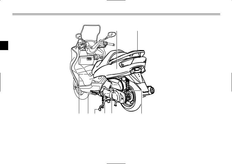
EAU00026
DESCRIPTION
Partlocations
Left view
1 2
2
|
8 |
7 |
6 |
5 |
4 |
3 |
|
1. |
Rear storage compartment |
(page 3-20) |
5. |
V-belt case air filter element |
(page 6-22) |
|
2. |
Grab bar |
(page 5-2) |
6. |
Centerstand |
(page 6-31) |
|
3. |
Shock absorber spring preload |
7. |
Sidestand |
(page 3-22, 6-31) |
|
|
adjusting ring |
(page 3-21) |
8. |
Fuel tank cap |
(page 3-15) |
|
|
4. |
Air filter element |
(page 6-21) |
2-1

DESCRIPTION
12
|
18 |
17 |
16 |
15 14 |
13 |
||||||||||||
|
9. |
Passenger seat |
14. |
Battery |
(page 6-34) |
||||||||||||
|
10. |
Rider seat |
(page 3-18) |
15. |
Fuse box |
(page 6-36) |
|||||||||||
|
11. |
Air flow louver |
(page 6-23) |
16. |
Coolant reservoir cap |
(page 6-20) |
|||||||||||
|
12. |
Headlight |
(page 6-37) |
17. |
Coolant level check window |
(page 6-19) |
|||||||||||
|
13. |
Radiator |
18. |
Engine oil filler cap |
(page 6-15) |
2-2

DESCRIPTION
Controls and instruments
|
1 |
2 |
3 4 |
5 |
6 |
7 |
8 |
9 |
10 |
2
|
13 |
12 |
11 |
|||||||
|
1. |
Rear brake lever |
(page 3-12) |
8. |
Fuel gauge |
(page 3-5) |
||||
|
2. |
Left handlebar switches |
(page 3-10) |
9. |
Right handlebar switches |
(page 3-11) |
||||
|
3. |
Front storage compartment A |
(page 3-19) |
10. |
Front brake lever |
(page 3-11) |
||||
|
4. |
Coolant temperature gauge |
(page 3-5) |
11. |
Throttle grip |
(page 6-23, 6-31) |
||||
|
5. |
Tachometer |
(page 3-4) |
12. |
Front storage compartment B |
(page 3-20) |
||||
|
6. |
Speedometer |
(page 3-4) |
13. |
Main switch/steering lock |
(page 3-1) |
||||
|
7. |
Multi-function display |
(page 3-5) |
2-3

INSTRUMENT AND CONTROL FUNCTIONS
|
………………………………………………………….Main switch/steering lock |
3-1 |
||
|
Indicator and warning lights ……………………………………………………… |
3-2 |
||
|
Speedometer …………………………………………………………………………. |
3-4 |
||
|
Tachometer …………………………………………………………………………… |
3-4 |
||
|
Fuel gauge …………………………………………………………………………….. |
3-5 |
||
|
Coolant temperature gauge ……………………………………………………… |
3-5 |
3 |
|
|
Multi-function display |
3-5 |
||
|
Anti-theft alarm (optional) ………………………………………………………. |
3-10 |
||
|
Handlebar switches ………………………………………………………………. |
3-10 |
||
|
Front brake lever ………………………………………………………………….. |
3-11 |
||
|
Rear brake lever …………………………………………………………………… |
3-12 |
||
|
ABS ……………………………………………………………………………………. |
3-13 |
||
|
Fuel tank cap ……………………………………………………………………….. |
3-15 |
||
|
Fuel …………………………………………………………………………………….. |
3-16 |
||
|
Catalytic converter ………………………………………………………………… |
3-17 |
||
|
Rider seat ……………………………………………………………………………. |
3-18 |
||
|
Adjusting the rider seat ………………………………………………………….. |
3-18 |
||
|
Storage compartments ………………………………………………………….. |
3-19 |
||
|
Adjusting the shock absorber assemblies ………………………………… |
3-21 |
||
|
Sidestand …………………………………………………………………………….. |
3-22 |
||
|
Ignition circuit cut-off system ………………………………………………….. |
3-22 |
||

INSTRUMENT AND CONTROL FUNCTIONS
|
OFF |
ON |
|||
|
OPEN |
||||
|
PUSH |
||||
|
LOCK |
N |
|||
|
PUSH |
TO |
|||
|
P |
||||
|
I |
I |
|||
|
N |
||||
|
3 |
IG |
|||
EAU00029
Main switch/steering lock
Mainswitch/steeringlock
The main switch/steering lock controls the ignition and lighting systems, and is used to lock the steering. The various positions are described below.
EAU04580
ON
All electrical circuits are supplied with power; the meter lighting, taillight, license plate light and auxiliary light come on, and the engine can be started. The key cannot be removed.
NOTE:
The headlight comes on automatically when the engine is started and stays on until the key is turned to “OFF” or the sidestand is moved down.
EAU00038
OFF
All electrical systems are off. The key can be removed.
EAU00040
LOCK
The steering is locked, and all electrical systems are off. The key can be removed.
EAU00027
To lock the steering
1.Turn the handlebars all the way to the left.
2.Push the key in from the “OFF” position, and then turn it to “LOCK” while still pushing it.
3.Remove the key.
To unlock the steering
Push the key in, and then turn it to “OFF” while still pushing it.
EW000016
w
Never turn the key to “OFF” or “LOCK” while the scooter is moving, otherwise the electrical systems will be switched off, which may result in loss of control or an accident. Make sure that the scooter is stopped before turning the key to “OFF” or “LOCK”.
3-1
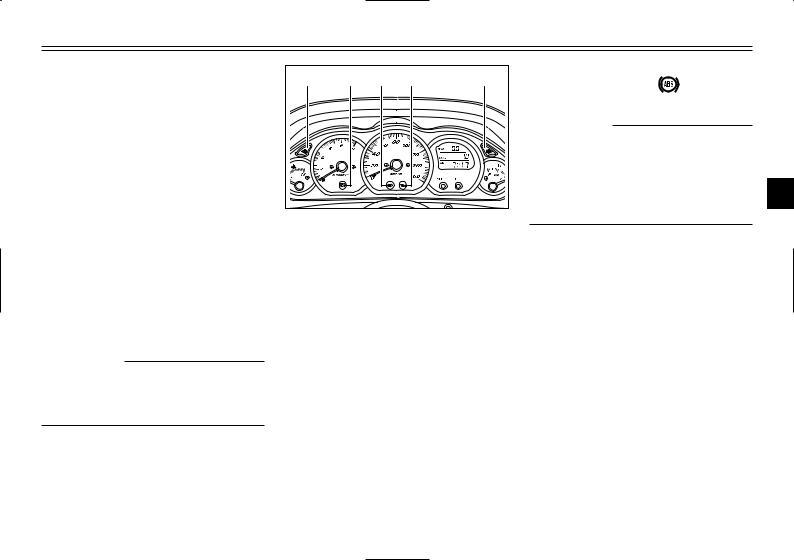
INSTRUMENT AND CONTROL FUNCTIONS
EAU03733
. (Parking)
The steering is locked, and the taillight, license light and auxiliary light are on, but all other electrical systems are off. The key can be removed.
To turn the main switch to “.”:
1.Turn the key to “LOCK”.
2.Slightly turn the key counterclockwise until it stops.
3.While still turning the key counterclockwise, push it in until it snaps into place.
ECA00043
cC
Do not use the parking position for an extended length of time, otherwise the battery may discharge.
|
1 |
2 |
3 |
4 |
5 |
1.Left turn signal indicator light “4”
2.ABS warning light “  ”
”
3.High beam indicator light “&”
4.Oil change indicator light “7”
5.Right turn signal indicator light “6”
EAU03034
Indicator and warning lights
Indicatorandwarninglights
EAU04121
Turn signal indicator lights “4” and “6”
Turnsignalindicatorlights
The corresponding indicator light flashes when the turn signal switch is pushed to the left or right.
EAU04901
|
ABS warning light “ |
” |
|
ABSwarninglight |
|
|
ECA00019 |
|
|
cC |
If the ABS warning light comes on or flashes while riding, the ABS may be defective. If this occurs,
have a Yamaha dealer check the 3 electrical circuit.
See page 3-13 for an explanation of the ABS.
The electrical circuit of the warning light can be checked by setting the engine stop switch to “#” and turning the key to “ON”.
The warning light should come on for a few seconds, and then go off. If the warning light does not come on or remains on, have a Yamaha dealer check the electrical circuit.
3-2

INSTRUMENT AND CONTROL FUNCTIONS
EWA00069
w
When the ABS warning light comes on or flashes while riding, the brake system reverts to conventional braking. Therefore, be careful not to cause the wheel to
3lock during emergency braking.
NOTE:
The ABS warning light may come on while pushing the start switch and while accelerating the engine with the scooter on its centerstand, but this does not indicate a malfunction.
EAU00063
High beam indicator light “&”
Highbeamindicatorlight
This indicator light comes on when the high beam of the headlight is switched on.
EAU03734
Oil change indicator light “7”
Oilchangeindicatorlight
This indicator light comes on at the initial 1,000 km and every 3,000 km thereafter to indicate that the engine oil should be changed.
If the engine oil is changed before the oil change indicator comes on (i.e. before the periodic oil change interval has been reached), the indicator light must be reset after the oil change for the next periodic oil change to be indicated at the correct time. (See page 6-17 for the resetting procedure.)
The electrical circuit of the indicator light can be checked according to the following procedure.
1.Set the engine stop switch to “#” and turn the key to “ON”.
2.Check that the indicator comes on for a few seconds and then goes off.
3.If the indicator light does not come on, have a Yamaha dealer check the electrical circuit.
NOTE:
The oil change indicator light may flash when the engine is revved with the scooter on the centerstand, but this does not indicate a malfunction.
3-3
![]()
INSTRUMENT AND CONTROL FUNCTIONS
|
1 |
1 |
||
|
1. |
Speedometer |
1. |
Tachometer |
|
ECA00134 |
||
|
cC |
||
|
8 |
Do not operate the engine |
|
|
above 8,500 r/min. |
||
|
8 |
This scooter is equipped with |
|
|
an engine speed limiter, which |
||
|
prevents the engine speed |
||
|
from exceeding approximately |
3 |
|
|
9,000 r/min. |
EAU04581
Speedometer
Speedometer
The speedometer shows the riding speed.
When the key is turned to “ON”, the speedometer needle will move to 160 km/h and back to zero in order to test the electrical circuit.
EAU04582
Tachometer
Tachometer
The electric tachometer allows the rider to monitor the engine speed and keep it within the ideal power range.
When the key is turned to “ON”, the tachometer needle will move to the 10,000 r/min and back to zero r/min in order to test the electrical circuit.
3-4

INSTRUMENT AND CONTROL FUNCTIONS
1
3
1. Fuel gauge
EAU00110
Fuel gauge
Fuelgauge
The fuel gauge indicates the amount of fuel in the fuel tank. The needle moves towards “E” (Empty) as the fuel level decreases. When the needle reaches “E”, approximately 2 L of fuel remain in the fuel tank. If this occurs, refuel as soon as possible.
NOTE:
Do not allow the fuel tank to empty itself completely.
2
1
1.Coolant temperature gauge
2.Red mark
EAU03124
Coolant temperature gauge
Coolanttemperaturegauge
This gauge indicates the coolant temperature when the main switch is on. The engine operating temperature will vary with changes in weather and engine load. If the needle points to the red mark, stop your scooter and let the engine cool. (See page 6-44 for details.)
EC000002
cC
Do not operate the engine if it is overheated.
1.Tripmeter
2.Odometer, fuel tripmeter
3.Clock, outside temperature and voltage display
EAU04906
Multi-function display
Display,multi-function
The multi-function display is equipped with the following:
8a tripmeter (which shows the distance traveled since it was last set to zero)
8a fuel tripmeter (which shows the distance traveled when the fuel
level reaches approximately 2.0 L)
8an odometer (which shows the total distance traveled)
8a clock
8an outside temperature display
3-5

INSTRUMENT AND CONTROL FUNCTIONS
1.“SELECT” button
2.“RESET” button
8a voltage display (which shows the battery voltage)
NOTE:
8When the key is turned to “ON”, all segments of the display come on for a few seconds. During this time, the multi-function display is performing a self-test.
8Be sure to turn the key to “ON” before using the “SELECT” and “RESET” buttons.
|
NOTE: |
||||||||
|
8 |
The tripmeter reset mode auto- |
|||||||
|
matically cancels after five sec- |
||||||||
|
onds. To return to the reset |
||||||||
|
mode, push the “SELECT” but- |
||||||||
|
ton again until “Trip” begins |
||||||||
|
flashing. |
||||||||
|
3 |
||||||||
|
8 |
To cancel the tripmeter reset |
|||||||
|
mode, push the “SELECT” but- |
||||||||
|
Tripmeter “Trip” |
ton. |
|||||||
|
8 |
If the tripmeter indicates “–––– ”, |
|||||||
|
To reset the tripmeter: |
have a Yamaha dealer check or |
|||||||
|
1. Push the “SELECT” button until |
repair the multi-function display |
|||||||
|
the voltage display appears, then |
as it may be faulty. |
|||||||
|
push the “SELECT” button one |
||||||||
|
more time and “Trip” starts flash- |
||||||||
|
ing. |
2.Push the “RESET” button for at least one second to reset the tripmeter to zero.
3-6
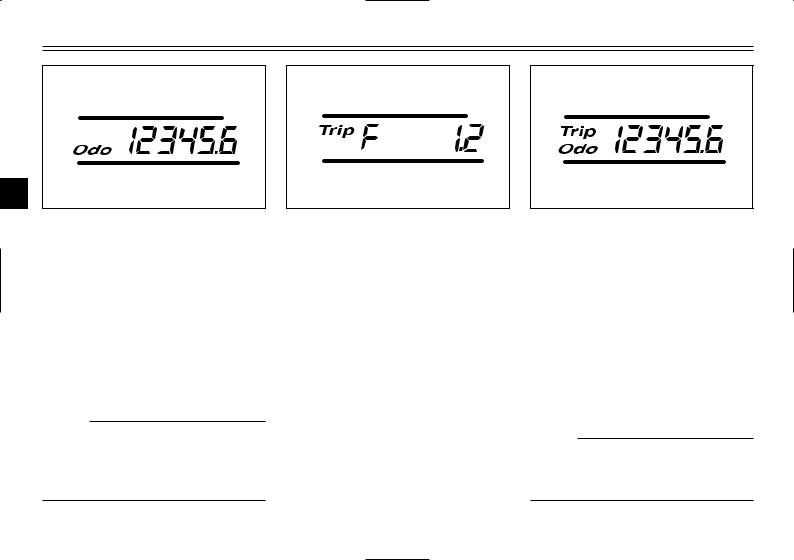
INSTRUMENT AND CONTROL FUNCTIONS
3
Odometer “Odo”
The odometer has two functions.
8It shows the total distance traveled.
8It automatically changes to the fuel tripmeter mode “Trip F” when the fuel level reaches approximately 2.0 L. (See “Fuel tripmeter” for details.)
NOTE:
If the odometer indicates “–––––– ”, have a Yamaha dealer check or repair the multi-function display as it may be faulty.
Fuel tripmeter “Trip F”
When the fuel level reaches approximately 2.0 L, the odometer display automatically changes to the fuel tripmeter mode “Trip F” and starts counting the distance traveled from that point. After refueling and traveling 5 km, the odometer display returns to “Odo”.
To return to the odometer mode before refueling, push the “SELECT” button until “Trip F” begins flashing (“Trip F” will only flash for five seconds). While “Trip F” is flashing, push the “RESET” button for at least one second and the display will return to the odometer mode. From that time, both “Trip” and “Odo” are displayed until you refuel and travel 5 km.
NOTE:
The display cannot be changed back to “Trip F” after pushing the “RESET” button.
3-7

INSTRUMENT AND CONTROL FUNCTIONS
3
|
Clock |
3. When the hour digits start flash- |
4. |
Push the “SELECT” button, and |
|
|
To set the clock |
ing, push the “RESET” button to |
the minute digits will start flash- |
||
|
1. |
Push the “SELECT” button until |
set the hours. |
ing. |
|
|
the clock is displayed. |
5. |
Push the “RESET” button to set |
||
|
2. |
Push the “SELECT” button and |
the minutes. |
||
|
“RESET” button together for at |
6. |
Push the “SELECT” button and |
||
|
least two seconds. |
then release it to start the clock. |
3-8
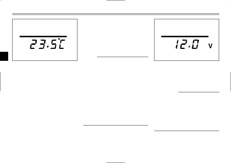
INSTRUMENT AND CONTROL FUNCTIONS
3
Outside temperature display
This display shows the outside temperature from -10.0 °C to 50.0 °C in 0.5 °C increments.
8When the outside temperature falls below -10.0 °C, “–– °C ” is displayed.
8When the outside temperature climbs above 50.0 °C, “50.0” flashes.
NOTE:
8If “–– °C” is displayed or “50.0” flashes while the outside temperature is between -10.0 °C and 50.0 °C, there is a problem with the electrical circuit. Have a Yamaha dealer check or repair the electric circuit.
8The accuracy of the temperature reading may be affected when riding slowly (approximately under 20 km/h) or when stopped at traffic signals, railroad crossings, etc.
Voltage display
This display shows the battery voltage.
ECA00135
cC
If the voltage display indicates “LO” or “HI”, there may be trouble with the battery charging circuit or the battery may be faulty. If “LO” or “HI” appears in the display, have a Yamaha dealer check or repair the scooter.
3-9

INSTRUMENT AND CONTROL FUNCTIONS
EAU00109
Anti-theft alarm (optional)
Anti-theftalarm(optional)
This scooter can be equipped with an optional anti-theft alarm by a Yamaha dealer. Contact a Yamaha dealer for more information.
1.Pass switch “PASS”
2.Dimmer switch “&/%”
3.Turn signal switch “4/6”
4.Horn switch “*”
EAU00118
Handlebar switches
Handlebarswitches
EAU00120
Pass switch “PASS”
Passswitch
Press this switch to flash the headlight.
EAU03888
Dimmer switch “&/%”
Dimmerswitch
Set this switch to “&” for the high beam and to “%” for the low beam.
|
EAU03889 |
|
|
Turn signal switch “4/6” |
|
|
Turnsignalswitch |
|
|
To signal a right-hand turn, push this |
|
|
switch to “6”. To signal a left-hand |
|
|
turn, push this switch to “4”. When |
|
|
released, the switch returns to the |
|
|
center position. To cancel the turn |
|
|
signal lights, push the switch in after |
3 |
|
it has returned to the center position. |
|
EAU00129
Horn switch “*”
Hornswitch
Press this switch to sound the horn.
3-10

INSTRUMENT AND CONTROL FUNCTIONS
1
1.Engine stop switch “#/$”
2.Start switch “,”
EAU03890
Engine stop switch “#/$”
Enginestopswitch
Set this switch to “#” before starting the engine. Set this switch to “$” to stop the engine in case of an emergency, such as when the scooter overturns or when the throttle cable is stuck.
EAU03801
Start switch “,”
Startswitch
With the sidestand up, push this switch while applying the front or rear brake to crank the engine with the starter.
EC000005
cC
See page 5-1 for starting instructions prior to starting the engine.
1
1. Front brake lever
EAU03882
Front brake lever
Brakelever,front
The front brake lever is located on the right handlebar grip. To apply the front brake, pull this lever toward the handlebar grip.
3-11

INSTRUMENT AND CONTROL FUNCTIONS
1
3
1. Rear brake lever
EAU00163
Rear brake lever
Brakelever,rear
The rear brake lever is located on the left handlebar grip. To apply the rear brake, pull this lever toward the handlebar grip.
3-12

INSTRUMENT AND CONTROL FUNCTIONS
EAU03631
ABS
ABS
The Yamaha ABS (Anti-lock Brake System) features a dual electronic control system, which acts on the front and rear brakes independently. The ABS securely controls wheel
3lockup during emergency braking on changing road surfaces and under various weather conditions, thereby maximizing tire adhesion and performance while providing a smooth braking action. The ABS is monitored by an ECU (Electronic Control Unit), which will have recourse to manual braking if a malfunction occurs.
8The ABS performs best on long braking distances.
8On certain (rough or gravel) roads, the braking distance may be longer with than without the ABS. Therefore, always keep a sufficient distance to the vehicle ahead to match the riding speed.
8When the ABS is activated, the brakes are operated in the usual way. A pulsating action may be felt at the brake levers, but this does not indicate a malfunction.
8This ABS has a test mode which allows the owner to experience the pulsating at the brake levers when the ABS is operating. However, special tools are required, so please consult your Yamaha dealer when performing this test.
3-13
![]()
|
INSTRUMENT AND CONTROL FUNCTIONS |
|||||||
|
ABS components |
1. |
Front brake hose |
|||||
|
2. |
Rear brake hose |
||||||
|
3. |
ABS warning light |
||||||
|
1 |
2 |
4. Fail-safe relay |
|||||
|
5. ECU (Electronic Control Unit) |
|||||||
|
3 |
4 |
5 |
6. |
Stop relay |
|||
|
7. |
Hydraulic Unit (HU) |
||||||
|
6 |
8. |
Front brake hose |
3 |
||||
|
9. Front wheel sensor rotor |
|||||||
|
10.Front wheel sensor |
|||||||
|
7 |
11.Fuse boxes |
||||||
|
15 |
12.ABS test coupler |
||||||
|
13.Rear brake hose |
|||||||
|
8 |
|||||||
|
14.Rear wheel sensor rotor |
|||||||
|
15.Rear wheel sensor |
|||||||
|
9 |
|||||||
|
14 |
|||||||
|
13 |
|||||||
|
12 |
10 |
||||||
|
11 |
|||||||
|
3-14 |

INSTRUMENT AND CONTROL FUNCTIONS
1.Lid
2.Lever
EAU03090
Fuel tank cap
Fueltankcap
To open the fuel tank cap
1.Open the lid by sliding the lever forward, and then pull the lever up.
1.Fuel tank cap
2.Insert the key into the lock and turn it clockwise. The lock will be released and the fuel tank cap can be removed.
1. Match marks
To install the fuel tank cap
1.Align the match marks, insert the fuel tank cap into the tank opening, and then push down on the cap.
2.Turn the key counterclockwise to the original position, and then remove it.
3.Close the lid.
EWA00028
w
Be sure that the fuel tank cap is properly installed and locked before riding the scooter.
3-15

INSTRUMENT AND CONTROL FUNCTIONS
1.Filler tube
2.Fuel level
EAU03753
Fuel
Fuel
Make sure that there is sufficient fuel in the tank. Fill the fuel tank to the bottom of the filler tube as shown.
EW000130
w
8Do not overfill the fuel tank, otherwise it may overflow when the fuel warms up and expands.
8Avoid spilling fuel on the hot engine.
EAU00185
cC
Immediately wipe off spilled fuel with a clean, dry, soft cloth, since fuel may deteriorate painted surfaces or plastic parts.
EAU04284
Recommended fuel: REGULAR UNLEADED GASOLINE ONLY
Fuel tank capacity: Total amount:
12 L
3
ECA00104
cC
Use only unleaded gasoline. The use of leaded gasoline will cause severe damage to internal engine parts, such as the valves and piston rings, as well as to the exhaust system.
3-16

INSTRUMENT AND CONTROL FUNCTIONS
Your Yamaha engine has been designed to use regular unleaded gasoline with a research octane number of 91 or higher. If knocking (or pinging) occurs, use a gasoline of a different brand or premium unleaded fuel. Use of unleaded fuel will extend
3spark plug life and reduce maintenance costs.
EAU03098
Catalytic converter
Catalyticconverter
This scooter is equipped with a catalytic converter in the muffler.
EW000128
w
The exhaust system is hot after operation. Make sure that the exhaust system has cooled down before doing any maintenance work.
EC000114
cC
The following precautions must be observed to prevent a fire hazard or other damages.
8Use only unleaded gasoline. The use of leaded gasoline will cause unrepairable damage to the catalytic converter.
8Never park the scooter near possible fire hazards such as grass or other materials that easily burn.
8Do not allow the engine to idle too long.
3-17

INSTRUMENT AND CONTROL FUNCTIONS
a
ON
OFF
OPEN
PUSH
LOCK
|
PUSH |
TO |
||
|
P |
|||
|
I |
I |
||
|
N |
|||
|
IG |
|
a. Open. |
1. Rider seat |
1. Rider seat |
|
|
EAU03091 |
3. Fold the rider seat up. |
EAU03096* |
|
|
Rider seat |
Adjusting the rider seat |
||
Riderseat,adjusting
Riderseat
To open the rider seat
1.Place the scooter on the centerstand.
2.Insert the key into the main switch, and then turn it counterclockwise.
NOTE:
Do not push inward when turning the key.
To close the rider seat
1.Fold the rider seat down, and then push it down to lock it in place.
2.Remove the key from the main switch if the scooter will be left unattended.
NOTE:
Make sure that the seat is properly secured before riding.
The rider seat can be adjusted as follows to change the riding position.
1. Open the rider seat.
3-18
 Loading…
Download Service manual of Yamaha MAJESTY YP250 Motorcycle, Scooter for Free or View it Online on All-Guides.com.

1

2

3

4

5

6

7

8

9

10

11

12

13

14

15

16

17

18

19

20

21

22

23

24

25

26

27

28

29

30

31

32

33

34

35

36

37

38

39

40

41

42

43

44

45

46

47

48

49

50

51

52

53

54

55

56

57

58

59

60

61

62

63

64

65

66

67

68

69

70

71

72

73

74

75

76

77

78

79

80

81

82

83

84

85

86

87

88

89

90

91

92

93

94

95

96

97

98

99

100

101

102

103

104

105

106

107

108

109

110

111

112

113

114

115

116

117

118

119

120

121

122

123

124

125

126

127

128

129

130

131

132

133

134

135

136

137

138

139

140

141

142

143

144

145

146

147

148

149

150

151

152

153

154

155

156

157

158

159

160

161

162

163

164

165

166

167

168

169

170

171

172

173

174

175

176

177

178

179

180

181

182

183

184

185

186

187

188

189

190

191

192

193

194

195

196

197

198

199

200

201

202

203

204

205

206

207

208

209

210

211

212

213

214

215

216

217

218

219

220

221

222

223

224

225

226

227

228

229

230

231

232

233

234

235

236

237

238

239

240

241

242

243

244

245

246

247

248

249

250

251

252

253

254

255

256

257

258

259

260

261

262

263

264

265

266

267

/Factory service manual for Yamaha YP250 ATV (quad). Serves equally well for the Linhai 250cc Bighorn of same vintage as they are identical. This manual is more accurate than the Linhai document


EB000000
YP250SERVICE MANUAL
1996 by Yamaha Motor Co., Ltd.1st Edition, January 1996
All rights reserved. Any reprinting orunauthorized use without the writtenpermission of Yamaha Motor Co., Ltd.
is expressly prohibited.

NOTE:
CAUTION:
EB001000
NOTICEThis manual was produced by the Yamaha Motor Company primarily for use by Yamaha dealers andtheir qualified mechanics. It is not possible to include all the knowledge of a mechanic in one manual,so it is assumed that anyone who uses this book to perform maintenance and repairs on Yamahascooter has a basic understanding of the mechanical ideas and the procedures of scooter repair. Re-pairs attempted by anyone without this knowledge are likely to render the scooter unsafe and unfit foruse.
Yamaha Motor Company, Ltd. is continually striving to improve all its models. Modifications and signifi-cant changes in specifications or procedures will be forwarded to all authorized Yamaha dealers andwill appear in future editions of this manual where applicable.
Designs and specifications are subject to change without notice.
IMPORTANT INFORMATIONParticularly important information is distinguished in this manual by the following notations.
The Safety Alert Symbol means ATTENTION! BECOME ALERT! YOURSAFETY IS INVOLVED!
Failure to follow WARNING instructions could result in severe injury or death tothe scooter operator, a bystander or a person inspecting or repairing the scoot-er.
A CAUTION indicates special precautions that must be taken to avoid damageto the scooter.
NOTE: A NOTE provides key information to make procedures easier or clearer.

12 4 3
5
6
7
6
8
YP002000
HOW TO USE THIS MANUALMANUAL ORGANIZATIONThis manual consists of chapters for the main categories of subjects. (See “Illustrated symbols”)
1st title 1 : This is the title of the chapter with its symbol on the upper right corner of each page.
2nd title 2 : This title indicates the section of the chapter and only appears on the first page of eachsection. It is located in the upper left corner of the page.
3rd title 3 : This title indicates a sub-section that is followed by step-by-step procedures accompa-nied by corresponding illustrations.
EXPLODED DIAGRAMSTo heps identify parts and clarify procedure steps, there are exploded diagrams at start of each remov-al and disassembly section.
1. An easy-to-see exploded diagram 4 is provided for disassembly and assembly jobs.2. Numbers 5 are given in the order of jobs in the exploded diagram. A number that is enclosed by a
circle indicates a disassembly step.3. An explanation of jobs and notes is presented in an easy-to-read way by the use of symbol marks
6 . The meanings of the symbol marks are given on the next page.4. A job instruction chart 7 accompanies the exploded diagram, providing the order of jobs, names
of parts, notes in jobs, etc.5. For jobs requiring more information, the step-by-step format supplements 8 are given in addition
to the exploded diagram and the job instruction chart.

1
3
5
7
9
11
13
15
18
2
4
8
10
12
14
16
6
21
24 25
17
19 20
22 23
EB003000
ILLUSTRATED SYMBOLSIllustrated symbols 1 to 9 are designed asthumb tabs to indicate the chapter’s numberand content.
1 General information2 Specifications3 Periodic inspection and adjustment4 Engine5 Cooling system6 Carburetion7 Chassis8 Electrical9 Troubleshooting
Illustrated symbols 10 to 17 are used to identifythe specifications appearing in the text.
10 Possible to maintain with engine mounted11 Filling fluid12 Lubricant13 Special tool14 Tightening15 Wear limit, clearance16 Engine speed17 Ω, V, A
Illustrated symbols 18 to 23 in the exploded dia-grams indicate the types of lubricants and lu-brication points.
18 Apply engine oil19 Apply gear oil20 Apply molybdenum disulfide oil21 Apply wheel bearing grease22 Apply lightweight lithium-soap base grease23 Apply molybdenum disulfide grease
Illustrated symbols 24 to 25 in the exploded dia-grams indicate the where to apply locking agent24 and when to install new parts 25 .
24 Apply locking agent (LOCTITE )25 Use new one

GENERAL INFORMATION
SPECIFICATIONS
PERIODIC INSPECTION AND ADJUSTMENT
ENGINE OVERHAUL
COOLING SYSTEM
CARBURETION
CHASSIS
ELECTRICAL
TROUBLESHOOTING
GENINFO 1SPEC 2INSPADJ 3ENG 4
COOL 5CARB 6CHAS 7ELEC 8TRBLSHTG 9
INDEX


CHAPTER 1GENERAL INFORMATION
SCOOTER IDENTIFICATION 1-1. . . . . . . . . . . . . . . . . . . . . . . . . . . . . . . . . . . . VEHICLE IDENTIFICATION NUMBER (for E) 1-1. . . . . . . . . . . . . . . . . . . FRAME SERIAL NUMBER 1-1. . . . . . . . . . . . . . . . . . . . . . . . . . . . . . . . . . . ENGINE SERIAL NUMBER 1-1. . . . . . . . . . . . . . . . . . . . . . . . . . . . . . . . . . MODEL LABEL 1-1. . . . . . . . . . . . . . . . . . . . . . . . . . . . . . . . . . . . . . . . . . . . .
FEATURES 1-2. . . . . . . . . . . . . . . . . . . . . . . . . . . . . . . . . . . . . . . . . . . . . . . . . . . OIL INDICATOR LIGHT 1-2. . . . . . . . . . . . . . . . . . . . . . . . . . . . . . . . . . . . . . AUTO CHOKE SYSTEM 1-3. . . . . . . . . . . . . . . . . . . . . . . . . . . . . . . . . . . . . IGNITION CIRCUIT CUT-OFF SYSTEM 1-3. . . . . . . . . . . . . . . . . . . . . . .
IMPORTANT INFORMATION 1-4. . . . . . . . . . . . . . . . . . . . . . . . . . . . . . . . . . . . PREPARATION FOR REMOVAL PROCEDURES 1-4. . . . . . . . . . . . . . . REPLACEMENT PARTS 1-4. . . . . . . . . . . . . . . . . . . . . . . . . . . . . . . . . . . . . GASKETS, OIL SEALS, AND O-RINGS 1-4. . . . . . . . . . . . . . . . . . . . . . . . LOCK WASHERS/PLATES AND COTTER PINS 1-5. . . . . . . . . . . . . . . . BEARINGS AND OIL SEALS 1-5. . . . . . . . . . . . . . . . . . . . . . . . . . . . . . . . . CIRCLIPS 1-5. . . . . . . . . . . . . . . . . . . . . . . . . . . . . . . . . . . . . . . . . . . . . . . . . . CHECKING OF CONNECTIONS 1-6. . . . . . . . . . . . . . . . . . . . . . . . . . . . . . HOW TO USE THE CONVERSION TABLE 1-7. . . . . . . . . . . . . . . . . . . . .
SPECIAL TOOLS 1-8. . . . . . . . . . . . . . . . . . . . . . . . . . . . . . . . . . . . . . . . . . . . . .


1-1
SCOOTER IDENTIFICATIONGENINFO
NOTE:
NOTE:
YP100000
GENERAL INFORMATIONSCOOTER IDENTIFICATION
YP100010
VEHICLE IDENTIFICATION NUMBER (for E)The vehicle identification number 1 is stampedinto the right side of the frame.
The vehicle identification number is used toidentify your scooter and may be used to regis-ter your scooter with the licensing authority inyour country.
YP100020
FRAME SERIAL NUMBER (except for E)The frame serial number 1 is stamped into theright side of the frame.
EB100030
ENGINE SERIAL NUMBERThe engine serial number 1 is stamped into thecrankcase.
Designs and specifications are subject tochange without notice.
MODEL LABELThe model label 1 is affixed under the seat.This information will be needed to order spareparts.

1-2
FEATURESGENINFO
Engine stopswitchMain
switch
Oil indicator light
Fuse
Battery Meter
Reset button
Ignitor unit
C.P.U
Oil indicator lightReset button
NOTE:
FEATURESOIL INDICATOR LIGHTFunctionPulses (travel distance signals) from the speedometer are counted and cause the oil indicator light tocome on at 1,000 km for the first time and thereafter every 3,000 km. In this way, this light indicates thetime for oil change.
Circuit diagram
Resetting procedureTravel distance can be reset if the reset button is held down for 2 to 5 seconds with the main switch“ON”.
1) If the “resetting” is done while the oil light is on, the oil indicator light goes off for resetting con-firmation.
2) If the “resetting” is done while the oil light is off, the oil indicator light comes on for 1.4 secondsfor resetting confirmation.
Failure diagnosis1) Checking oil indicator light for breakage
This oil indicator light is kept on for 1.4 seconds immediately after the main switch is turned on,thereby checking the bulb for breakage.
2) In case of meter pulse failureIf travel distance signals are not detected during running, the oil indicator light flashes and gives awarning of meter signal failure.
This circuit may be activated if the engine is accelerated without load with the mainestand put up.
Battery tending to discharge.If the starting motor is run with the battery tending to discharge, the oil indicator light may come on (for1.4 seconds), but this is noting abnormal.In this case recharge or replace battery.
This light comes on if battery charging becomes poor, thereby causing the engine to runas low as about 200 rpm against 600 rpm or so,

1-3
FEATURESGENINFO
Main switch
Fuse
Battery
Thermoswitch
Auto-choke
Igniter unit
C.P.UIgnition
Main switch Engine stop switch
Brakeswitch
Fuse
Starter relayRelay
Ignitor unit
BatteryStartermotor
Startswitch
Brake lightSidestandswitch
AUTO-CHOKE SYSTEMThis system is the parallel connection of the ignitor unit circuit and the thermo switch as shown, detect-ing the engine temperature, and facilitates the restarting with the warm engine.Circuit diagram
Auto-choke operation
Engine conditionStart with thecold engine
Crank with thecold engine
Crank with thewarm engine
Restart with thewarm engine
Thermo switch OFF OFF ON ON
Ignitor unit circuit OFF ON ON OFF
Auto-choke Activates Activates Not activate Not activate
IGNITION CIRCUIT CUT-OFF SYSTEMA sidestand circuit is added to the existing electric starting circuit, thereby controlling the starter motoroperation and the ignition system of the igniter unit.Circuit diagram
Operating mode
Sidestand switchOperation of brake
lightOperation of starter
motorOperation of igniter
unit control
OFF ON Not operated Misfire(Sidestand in use) OFF Not operated Misfire
ON ON Operated Ignited(Sidestand folded in) OFF Not operated Ignited (ridden)

1-4
IMPORTANT INFORMATIONGENINFO
EB101000
IMPORTANT INFORMATIONPREPARATION FOR REMOVAL PROCE-DURES
1. Remove all dirt, mud, dust and foreign ma-terial before removal and disassembly.
2. Use proper tools and cleaning equipment.3. Refer to the “SPECIAL TOOLS” section.
4. When disassembling the machine, alwayskeep mated parts together. This includesgears, cylinders, pistons and other partsthat have been “mated” through normalwear. Mated parts must always be reusedor replaced as an assembly.
5. During machine disassembly, clean allparts and place them in trays in the order ofdisassembly. This will speed up assemblyand allow for the correct installation of allparts.
6. Keep all parts away from any source of fire.
EB101010
REPLACEMENT PARTS1. Use only genuine Yamaha parts for all re-
placements. Use oil and grease recom-mended by Yamaha for all lubrication jobs.Other brands may be similar in function andappearance, but inferior in quality.
EB101020
GASKETS, OIL SEALS AND O-RINGS1. Replace all gaskets, seals and O-rings
when overhauling the engine. All gasketsurfaces, oil seal lips and O-rings must becleaned.
2. Properly oil all mating parts and bearingsduring reassembly. Apply grease to the oilseal lips.

1-5
IMPORTANT INFORMATIONGENINFO
OR
CAUTION:
EB101030
LOCK WASHERS/PLATES AND COTTER PINS
1. Replace all lock washers/plates and cotterpins after removal. Bend lock tabs along thebolt or nut flats after the bolt or nut has beentightened to specification.
EB101040
BEARINGS AND OIL SEALSInstall bearings and oil seals so that themanufacturer’s marks or numbers are visible.When installing oil seals, apply a light coating oflightweight lithium base grease to the seal lips.Oil bearings liberally when installing, if appropri-ate.
1 Oil seal
Do not use compressed air to spin the bearingsdry. This will damage the bearing surfaces.
1 Bearing
EB101050
CIRCLIPS1. Check all circlips carefully before reas-
sembly. Always replace piston pin clips af-ter one use. Replace distorted circlips.When installing a circlip 1 , make sure thatthe sharp-edged corner 2 is positioned op-posite the thrust 3 it receives. See section-al view.
4 Shaft

1-6
IMPORTANT INFORMATIONGENINFO
NOTE:
NOTE:
EB801000
CHECKING OF CONNECTIONSDealing with stains, rust, moisture, etc. on theconnector.
1. Disconnect:Connector
2. Dry each terminal with an air blower.
3. Connect and disconnect the connector twoor three.
4. Pull the lead to check that it will not comeoff.
5. If the terminal comes off, bend up the pin 1and reinsert the terminal into the connector.
6. Connect:Connector
The two connectors “click” together.
7. Check for continuity with a tester.
If there is no continuity, clean the terminals. Be sure to perform the steps 1 to 7 listed
above when checking the wireharness. For a field remedy, use a contact revitalizer
available on the market. Use the tester on the connector as shown.

1-7
HOW TO USE THE CONVERSION TABLEGENINFO
EB201000
HOW TO USE THE CONVERSION TABLEAll specification data in this manual are listed in SI and METRIC UNITS.Use this table to convert METRIC unit data to IMPERIAL unit data.Ex.
METRIC MULTIPLIER IMP**mm 0.03937 = ** in2 mm 0.03937 = 0.08 in
CONVERSION TABLE
METRIC TO IMP
Known Multiplier Result
Torque
mkgmkgcmkgcmkg
7.23386.7940.07230.8679
ftlbinlbftlbinlb
Weightkgg
2.2050.03527
lboz
Distance
km/hrkmmmcmmm
0.62140.62143.2811.0940.39370.03937
mphmiftydinin
Volume/Capacity
cc (cm3)cc (cm3)lit (liter)lit (liter)
0.035270.061020.87990.2199
oz (IMP liq.)cuinqt (IMP liq.)gal (IMP liq.)
Miscella-neous
kg/mmkg/cm2
Centigrade
55.99714.22349/5(C) + 32
lb/ inpsi (lb/ in2)Fahrenheit (F)

1-8
SPECIAL TOOLSGENINFO
EB102000
SPECIAL TOOLSThe following special tools are necessary for complete and accurate tune-up and assembly.Use only the appropriate special tools; this will help prevent damage caused by the use of inappropri-ate tools or improvised techniques.When placing an order, refer to the list provided below to avoid any mistakes.
Tool No. Tool name/Usage Illustration
90890-01084-01085
WeightRocker arm shaft puller bolt
These tools are used when removingor installing the rocker arm shafts.
90890-01235 Rotor holding tool
This tool is used to remove theflywheel magneto.
90890-01268 Ringnut wrench
This tool is used to loosen and tightenthe exhaust and steering ringnut.
90890-01311 Valve adjusting tool
This tool is necessary for adjustingvalve clearance.
90890-01312 Fuel level gauge
This gauge is used to measure the fuellevel in the float chamber.
90890-01325-01352
Radiator cap testerAdaptor
These tools are used for checking thecooling system.
90890-01326-04084
T-handleDamper rod holder
These tool are used for holding thedamper rod holder when removing orinstalling the damper rod holder.
90890-01337-01464
Clutch spring compressorClutch spring holder arm
These tools are used for removing thenut with holding the compression spring.
90890-01348 Locknut wrench
This tool is used when removing orinstalling the secondary sheave nut.

1-9
SPECIAL TOOLSGENINFO
Tool No. Tool name/Usage Illustration
90890-01362 Flywheel puller
This tool is used for removing therotor.
90890-01367-01368
Fork seal driver weightFork seal driver attachment (ø33)
This tool is used when installing thefork seal.
90890-01384 Oil seal guide
This tool is used for protecting the oilseal lip when installing the secondarysliding sheave.
90890-01403 Ring nut wrench
This tool is used to loosen and tightenthe steering ring nut.
90890-01701 Sheave holder
This tool is used for holding thesecondary sheave.
90890-01996 Cylinder cup installer set
This tool is used for installing thecylinder cup to the master cylinderpiston.
90890-03079 Thickness gauge
This tool is used to measure the valveclearance.
90890-03081 Compression gauge
These tools are used to measure theengine compression.
90890-03112 Pocket tester
These instruments are invaluable forchecking the electrical system.
90890-03113 Engine tachometer
This tool is needed for detectingengine rpm.

1-10
SPECIAL TOOLSGENINFO
Tool No. Tool name/Usage Illustration
90890-03141 Timing light
This tool is needed for detectingignition timing.
90890-04101 Valve lapper
This tool is used for removing andinstalling the lifter and for lapping thevalve.
90890-04019-04108
Valve spring compressorAttachment
These tools are used when removingor installing the valve and the valvespring.
90890-04058-04078
Middle shaft bearing driverMechanical seal installer
These tools are used for installingmechanical seal.
90890-06754 Ignition checker
This instrument is necessary for checkingthe ignition system components.
90890-85505 Yamaha bond No. 1215
This sealant (bond) is used for crankcasemating surface, etc.

CHAPTER 2.SPECIFICATIONS
GENERAL SPECIFICATIONS 2-1. . . . . . . . . . . . . . . . . . . . . . . . . . . . . . . . . . . MAINTENANCE SPECIFICATIONS 2-4. . . . . . . . . . . . . . . . . . . . . . . . . . . . . .
ENGINE 2-4. . . . . . . . . . . . . . . . . . . . . . . . . . . . . . . . . . . . . . . . . . . . . . . . . . . CHASSIS 2-10. . . . . . . . . . . . . . . . . . . . . . . . . . . . . . . . . . . . . . . . . . . . . . . . . . ELECTRICAL 2-14. . . . . . . . . . . . . . . . . . . . . . . . . . . . . . . . . . . . . . . . . . . . . .
GENERAL TORQUE SPECIFICATIONS 2-16. . . . . . . . . . . . . . . . . . . . . . . . . . LUBRICATION POINTS AND GRADE OF LUBRICANT 2-17. . . . . . . . . . . .
ENGINE 2-17. . . . . . . . . . . . . . . . . . . . . . . . . . . . . . . . . . . . . . . . . . . . . . . . . . . CHASSIS 2-18. . . . . . . . . . . . . . . . . . . . . . . . . . . . . . . . . . . . . . . . . . . . . . . . . .
CABLE ROUTING 2-19. . . . . . . . . . . . . . . . . . . . . . . . . . . . . . . . . . . . . . . . . . . . .


2-1
GENERAL SPECIFICATIONS SPEC
SPECIFICATIONSGENERAL SPECIFICATIONS
Model YP250
Model code: 4UC 1 (except for CH, A)4UD1 (for CH, A)
Dimensions:Overall lengthOverall widthOverall heightSeat heightWheelbaseMinimum ground clearanceMinimum turning radius
2,110 mm,750 mm
1,330 mm,700 mm
1,500 mm,115 mm
2,600 mm
Basic weight:With oil and full fuel tank 158 kg
Engine:Engine typeCylinder arrangementDisplacementBore strokeCompression ratioCompression pressure (STD)Starting systemLubrication system:
Liquid-cooled 4-stroke, SOHCForward-inclined single cylinder0.249L (249 cm3)69.0 66.8 mm10 : 11,400 kPa (14 kg/cm2, 14 bar) at 500 r/minElectric starterWet sump
Oil type or grade:
Engine oilAPI STANDERD:SE or higher grade
Periodic oil changeTotal amount
Transmission oilTotal amount
1.2 L1.4 L
0.25 L
Radiator capacityTotal amount (including all routes) 1.4 L
Air filter: Carburetor sideCrankcase side
Wet type elementDry type element
Fuel:TypeFuel tank capacity
Regular unleaded gasoline11 L

2-2
GENERAL SPECIFICATIONS SPEC
Model YP250
Carburetor:Type/quantityManufacturer
Y28V-1A/1TEIKEI
Spark plug:TypeManufacturerSpark plug gap
DR8EANGK0.6 0.7 mm
Clutch type: Dry, centrifugal automatic
Transmission:Primary reduction systemPrimary reduction ratioSecondary reduction sytemSecondary reduction ratioTransmission typeOperationSingle speed automatic
Helical gear40/15 (2.666)Sper gear37/16 (2.312)Single speed automatic (V-belt type)Centrifugal automatic type2.20 0.88:1
Chassis:Frame typeCaster angleTrail
Steel tube underbone28103 mm
Tire:TypeSize front
rearManufacturer front
rearType front
rear
Tubeless110/90-12 64J130/70-12 62LIRC/CHENG SHINIRC/CHENG SHINMB61/C922MB61/C940
Tire pressure (cold tire):Maximum load-except motorcycleLoading condition A*
front rear
Loading condition B*front
rearHigh-speed riding
front rear
197 kg0 90 kg175 kPa (1.75 kg/cm2, 1.75 bar)200 kPa (2.0 kg/cm2, 2.0 bar)90 205 kg200 kPa (2.0 kg/cm2, 2.0 bar)225 kPa (2.25 kg/cm2, 2.25 bar)
200 kPa (2.0 kg/cm2, 2.0 bar)250 kPa (2.5 kg/cm2, 2.5 bar)
*Load is the total weight of cargo, rider, passenger, and accessories.

2-3
GENERAL SPECIFICATIONS SPEC
Model YP250
Brake:Front brake type
operationRear brake type
operation
Single disc brakeRight hand operationDrum brakeLeft hand operation
Suspension:Front suspensionRear suspension
Telescopic forkUnit swing
Shock absorber:Front shock absorberRear shock absorber
Coil spring/Oil damperCoil spring/Oil damper
Wheel travel:Front wheel travelRear wheel travel
85 mm90 mm
Electrical:Ignition systemGenerator systemBattery typeBattery capacity
T.C.I. (Digital)A.C. magnetoGT7B-512 V 6 AH
Headlight type: Quartz bulb (Halogen)
Bulb wattage quantity:HeadlightMarker lightTail /brake lightFlasher lightMeter lightHigh beam indicator lightOil indicator lightTurn indicator light
License light
12V 60 W/55 W 112V 4 W 112V 5 W/21 W 112V 21W 412V 1.7W 412V 3.4 W 112V 1.7 W 112V 3.4 W 212V 5 W 1

2-4
MAINTENANCE SPECIFICATIONS SPEC
Face Width Seat Width Margin Thickness
MAINTENANCE SPECIFICATIONSENGINE
Item Standard Limit
Cylinder head:Warp limit 0.03 mm
Cylinder:Bore sizeOut of round limit
69.000 69.005 mm
69.1 mm0.03 mm
Camshaft:Cam dimensionsIntake “A”
“B” “C”
Exhaust “A”“B”
“C”Camshaft runout limit
36.545 36.645 mm30.021 30.121 mm6.524 mm36.547 36.647 mm30.067 30.167 mm6.48 mm
36.45 mm29.92 mm
36.45 mm29.97 mm
0.03 mm
Cam chain:Cam chain type/No. of links DID SCA-0404A SDH/104
Rocker arm/rocker armshaft:Rocker arm inside diameterRocker shaft outside diameterRocker arm-to-rocker armshaftclearance
12.000 12.018 mm11.981 11.991 mm
0.009 0.012 mm
12.03 mm11.995 mm
Valve, valve seat, valve guide:Valve clearance (cold) IN
EX0.08 0.12 mm0.16 0.20 mm
Valve dimensions
“A” head diameter INEX
“B” face width INEX
“C” seat width INEX
“D” margin thickness INEX
Stem outside diameter INEX
Guide inside diameter INEX
33.9 34.1 mm28.4 28.6 mm3.394 3.960 mm3.394 3.960 mm0.9 1.1 mm0.9 1.1 mm0.8 1.2 mm0.8 1.2 mm5.975 5.990 mm5.960 5.975 mm6.000 6.012 mm6.000 6.012 mm
5.94 mm5.92 mm6.05 mm6.05 mm

2-5
MAINTENANCE SPECIFICATIONS SPEC
Item Standard Limit
Stem-to-guide clearance INEX
Stem runout limitValve seat width IN
EX
0.010 0.037 mm0.025 0.052 mm
0.9 1.1 mm0.9 1.1 mm
0.08 mm0.1 mm0.01 mm1.6 mm1.6 mm
Valve spring:Free length (Inner) IN/EXFree length (Outer) IN/EXSet length (valve closed) (Inner) IN/EXSet length (valve closed) (Outer) IN/EXCompressed pressure (Inner) IN/EX
(Outer) IN/EXTilt limit (Inner) IN/EXTilt limit (Outer) IN/EX
38.1 mm36.93 mm30.1 mm31.6 mm7.8 9.0 kg37.22 42.83 kg
36.1 mm35.0 mm
2.5/1.7 mm2.5/1.7 mm
Piston:Piston to cylinderclearancePiston size “D”Measuring point “H”Piston pin boreinside diameterPiston pin outside diameter
0.02 0.04 mm
68.965 68.980 mm5 mm17.004 17.015 mm
16.991 17.000 mm
0.15 mm
17.045 mm
16.975 mm
Piston rings:Top ring:TypeEnd gap (installed)Side clearance (installed)
2nd ring:TypeEnd gap (installed)Side clearance
Oil ring:End gap (installed)
Barrel0.15 0.30 mm0.04 0.08 mm
Taper0.30 0.45 mm0.03 0.07 mm
0.2 0.7 mm
0.45 mm0.12 mm
0.7 mm0.12 mm
Crankshaft:
Crank width “A”Runout limit “C”Big end side clearance “D”
59.95 60.00 mm0.03 mm0.35 0.85 mm

2-6
MAINTENANCE SPECIFICATIONS SPEC
Item Standard Limit
Automatic centrifugal clutch:Clutch shoe thicknessClutch housing inside diameterClutch shoe spring free lengthWeight outside diameterClutch – in revolutionClutch – stall revolution
3.0 mm135 mm28.1 mm20 mm2,100 2,700 r/min3,700 4,700 r/min
2.0 mm135.5 mm
19.5 mm
V-belt:V-belt width 22.6 mm 21.0 mm
Carburetor:TypeI.D. markVentuly outside diameterMain jet (M.J)Main air jet (M.A.J)Jet needle (J.N)Throttle valve size (Th.V)Pilot air jet (P.A.J.1)Needle jet (N.J)Pilot outlet (P.O)Pilot jet (P.J)Bypass (B.P)Pilot screw (P.S)Valve seat size (V.S)Starter jet 1 (G.S.1)Starter jet 2 (G.S.2)Float height (F.H)Engine idle speedIntake vacuum
Oil temperatureCooling water temperature
Y28V-1B-14UC 00 [4UD 00 (CH, A)]ø28#130ø0.95D32-3/511ø1.2ø2.585ø0.8#440.7 417/81.4ø0.45ø0.527 mm1,450 1,550 r/min220 260 mmHg65 75C80C
Fuel pump:TypeModel/manufacturer
Vaccum type4HC/MIKUNI
Oil pump:TypeTip clearanceSide clearanceHousing and rotor clearance
Trochoid type0.1 0.34 mm0.013 0.036 mm0.04 0.09 mm
0.4 mm0.15 mm0.15 mm

2-7
MAINTENANCE SPECIFICATIONS SPEC
Item Standard Limit
Radiator:TypeWidth/height/ thicknessRadiator cap opening pressure
Radiator capacityReservoir tank capacity
Cooling fin with electric fan140/238/24 mm110 140 kPa (1.1 1.4 kg/cm2,1.1 1.4 bar)1.4 L0.35 L
Thermostatic valve:Type/manufacturerValve opening temperatureValve full open temperatureValve full open lift
4HC/NIHON THERMOSTAT80.5 83.5C95C3 mm
Item Size
Bearings and oil seals:Big end bearingCrankshaft bearing (left)Crankshaft bearing (right)Crankshaft oil seal (left)Crankshaft oil seal (right)Water pump bearingWater pump oil sealMain axle bearing (left)Main axle bearing (right)Drive axle bearing (left)Drive axle bearing (right)Drive axle oil sealCamshaft bearing (left)Camshaft bearing (right)Primary drive gear bearing (left)Primary drive gear bearing (right)Primary drive gear oil seal
32 40 20 (needle bearing)630663/28SD-30-45-5S7-14-27-66000S-10-21-515NQ281515NQ281563036272SD8-32-52-760056202Z62056302SD8-32-52-7

2-8
MAINTENANCE SPECIFICATIONS SPEC
TIGHTENING TORQUESENGINE
Part to be tightened Part nameThread
sizeQ’ty
Tighteningtorque Remarksg
sizey
Nm mkg
Oil check boltExhaust pipe stud boltSpark plugCam sprocket coverCylinder head and cylinderCylinder head and cylinder(Cam chain side)Valve coverRotorValve adjuster locknutCam shaft bearing stopperCam sprocketCam chain tensioner(Body)(Plug)
Guide stopper 2Water pump housing coverHose jointThermostatic valve coverFiller neck supportingOil pump Oil pump coverDrain plugCarburetor jointCarburetor joint and carburetorAir filter assemblyAir filter coverFuel pumpExhaust pipe assemblyMufflerMuffler and exhaust pipeProtector (Muffler)Protector (Exhaust pipe)Crankcase (left and right)Drain boltOil fillerTransmission case coverCrankcase cover (left)Crankcase filter coverCrankcase cover protectorMagnet cover
———
BoltNutBolt
BoltNutNutBoltBolt
BoltBoltBoltBolt—
BoltBolt
ScrewBoltBoltBoltNutBolt
Screw—
NutBoltBolt
ScrewScrewBoltBoltBoltBoltBolt—
Bolt—
M6M8M12M6M8M6
M6M16M6M6M10
M6M8M6M6M6M6M5M6M3M35M6M6M6M5M6M8M10M8M6M6M6M8M14M8M6M6M6M6
121242
51221
2113221211222522313291161132
10
71318102210
1080148
60
108
10107
10571
32101071
10205320101010223
161077
10
0.71.31.81.02.21.0
1.08.01.40.86.0
1.00.81.01.00.71.00.50.70.13.21.01.00.70.11.02.05.32.01.01.01.02.20.31.61.00.70.71.0

2-9
MAINTENANCE SPECIFICATIONS SPEC
Part to be tightened Part nameThread
sizeQ’ty
Tighteningtorque Remarksg
sizey
Nm mkg
Cover (oil pump)Timing check plugOne way clutchClutch housingGrease stopper (Primary sheave)Primary fixed sheaveClutch carrier assemblyStatorPick up coilStarter motorThermo switchThermo unit
BoltPlug—
Bolt—————
Bolt——
M6M16M8M14M4M14M36M5M5M6M16
Pt 1/8
213141132221
128
30603
609077
10238
1.20.83.06.00.36.09.00.70.71.02.30.8

2-10
MAINTENANCE SPECIFICATIONS SPEC
CHASSIS
Item Standard Limit
Steering system:Steering bearing type Ball bearing
Front suspension:Front fork travelFork spring free lengthSpring rate (K1)Stroke (K1)Oil capacityOil levelOil gradeInner tube vend limit
100 mm265.8 mm5.7 N/mm (0.57 kg/mm)0 100 mm0.142 L (142 cm3)80 mmFork oil 15 WT or equivalent
263.5 mm
0.2 mm
Rear suspension:Shock absorber strokeSpring free lengthFitting lengthSpring rate (K1)
(K2)(K3)
Stroke (K1)(K2)(K3)
106 mm265 mm317 mm7.7 N/mm (0.77 kg/mm)10.9 N/mm (1.09 kg/mm)17.6 N/mm (1.76 kg/mm)0 40 mm40 75 mm75 106 mm
260 mm
Front wheel:TypeRim sizeRim materialRim runout limit radialRim runout limit lateral
Cast wheelMT2.75 12Aluminum
2 mm2 mm
Rear wheel:TypeRim sizeRim materialRim runout limit radialRim runout limit lateral
Cast wheelMT3.50 12Aluminum
2 mm2 mm
Front disc brake:TypeDisc outside diameter thicknessPad thicknessMaster cylinder inside diameterCaliper cylinder outside diameterBrake fluid type
Single245 4 mm5.4 mm12.7 mm25.4 + 30.1 mmDOT #4
0.8 mm

2-11
MAINTENANCE SPECIFICATIONS SPEC
Item Standard Limit
Rear drum brake:TypeDrum inside diameterShoe thickness
Leading, trailing160 mm4 mm
161 mm2 mm
Brake lever:Brake lever free play (front at lever side)Brake lever free play (rear)Throttle cable free play
2 5 mm10 20 mm3 5 mm
Item Size
Bearings and oil seals:Front wheel bearing (left)Front wheel bearing (right)Front wheel oil seal (left)Meter gear oil seal (right)Rear wheel bearing (left)Rear wheel oil seal (inner)Rear wheel oil seal (outer)
6302RS6302RSSD-22-42-7-1SDD-47-58-76302RSSDO-28-35-4DD-26-42-8

2-12
MAINTENANCE SPECIFICATIONS SPEC
TIGHTENING TORQUESCHASSIS
Part to be tightened Thread sizeTightening
torque RemarksNm mkg
Frame and engine bracketEngine bracket, compression rod and engineCompression rod and frameSidestand (bolt and frame)Sidestand (bolt and nut)Rear footrest bracketSwingarmRear shock absorber and frameRear shock absorber and engineSteering ring nutHandle holder and steering shaftHandle upper holder and lower holderBrake hose and master cylinderFuel tank
(font)(rear)
Fuel cockFuel senderFilterRoll over valveBoxHandle seatSheet lock assemblyPlastic parts & coverCowling staySide cover 1Cowling bodyFootrest boardHeadlight assemblyTail light assemblyFront wheel axle and nutRear wheel axle and nutRear brake cam leverRear pivot pinFront brake caliper and front forkBrake disc and hubBrake hose and caliperBrake caliper and bleed screwWindscreen
M12 1.25M10 1.25M10 1.25M10 1.25M10 1.25M 6 1.0M 8 1.25M10 1.25M 8 1.25M25 1.0M20 1.5M 8 1.25M10 1.25
M 6 1.0M 6 1.0M 6 1.0M 5 0.8M 6 1.0M 5 0.8M 6 1.0M 6 1.0M 6 1.0M 5 1.0M 8 1.25M 6 1.0M 6 1.0M 6 1.0M 6 1.0M 6 1.0M14 1.5M14 1.5M 6 1.0M10 1.25M10 1.25M 8 1.25M10 1.25M 7 1.0M 5 1.0
59326440407
23401922
1392326
10773747
1072
1677777
7013510324923266
0.4
5.93.26.44.04.00.72.34.01.92.2
13.92.32.6
1.00.70.70.30.70.40.71.00.70.21.60.70.70.70.70.77.0
13.51.03.24.92.32.60.6
0.04
See “NOTE”

2-13
MAINTENANCE SPECIFICATIONS SPEC
NOTE:1. First, tighten the ring nut (lower) approximately 38 Nm (3.8 mkg) by using the torque wrench, then
loosen the ring nut 1/4 turn.2. Second, tighten the ring nut (lower) approximately 22 Nm (2.2 mkg) by using the torque wrench,
then finger tighten the ring nut (center). Align the slots both ring nut and install the lock washer.3. Final, hold the ring nuts (lower and center) and tighten the ring nut (upper) 75 Nm (7.5 mkg) by
using the torque wrench.

2-14
MAINTENANCE SPECIFICATIONS SPEC
ELECTRICAL
Item Standard limit
Ignition timing:Ignition timing (B.T.D.C.)Advanced timing (B.T.D.C.)Advanced type
10 at 1,500 r/min32 at 5,000 r/minElectrical type
T.C.I.:Pickup coil resistance/color
T.C.I. unit model/manufacturer
168 252 Ω at 20C/Yellow – BlackJ4T069/MITSUBISHI
Ignition coil:Model/manufacturerMinimum spark gapPrimary winding resistanceSecondary winding resistance
F6T507/MITSUBISHI6 mm3.6 4.8 Ω at 20C10.7 14.5 kΩ at 20C
Spark plug cap:TypeResistance
Resin type5 kΩ
Charging system:TypeModel/manufacturerNormal outputStator coil resistance/color
A.C. magneto4HC/MITSUBISHI14 V 16 A at 5,000 r/min0.8 1.0 Ω at 20C/White – White
Rectifire/regulator:Model/manufacturerNo load regulated voltageCapacityWithstand voltage
SH640D-12/SHINDENGEN14.7 V20 A200 V
Battery:Specific gravity 1.310
Electric starter system:TypeStarter motor:Model/manufacturer / ID numberOperation voltageOutputArmature coil resistanceBrush overall lengthBrash quantitySpring forceCommutator diameterMica undercut (depth)
Constant mesh type
SM-13/MITSUBA/SM-1345412 V0.65 kW0.0012 0.0022 Ω at 20C12.5 mm2 pcs.570 920 g28 mm0.7 mm
4 mm
570 g27 mm

2-15
MAINTENANCE SPECIFICATIONS SPEC
Item Standard limit
Starter relay:Model/manufacturerAmperage ratingCoil winding resistance
4FL/JIDECO100 A4.2 4.6 Ω at 20C
Horn:Model/manufacturerMaximum amperage
YF-12/NIKKO2.5 A
Flasher relay:TypeModel/manufacturerFlasher frequency
Full transistor type4MY/NIPPONDENSO75 95 cycle/min
Fuel gage:Model/manufacturerSender unit resistance – fullSender unit resistance – empty
4HC/NIPPON SEIKI4 10 Ω90 100 Ω
Starting circuit cut-off relay:Model/manufacturerCoil winding resistance
4HC/MATSUSHITA72 88 Ω
Electric fan motor:Model/manufacturer 4HC/MITSUBA
Thermo switch (electric fan):Model/manufacturer 3LN/NIHON THERMOSTAT
Thermo switch (auto choke):Model/manufacturer 4HC/NIHON THERMOSTAT
Thermo unit:Model/manufacturer 2YK/NIPPON SEIKI
Circuit breaker:TypeMAINFANReserve
Fuse20 A 1 pc.3 A 1 pc.20 A 1 pc.3 A 1 pc.

2-16
GENERAL TORQUE SPECIFICATIONS SPEC
GENERAL TORQUE SPECIFICATIONSThis chart specifies torque for standard fasten-ers with standard I.S.O. pitch threads. Torquespecifications for special components or as-semblies are included in the applicable sectionsof this book. To avoid warpage, tighten multi-fastener assemblies in a crisscross fashion, inprogressive stages, until full torque is reached.Unless otherwise specified, torque specifica-tions call for clean, dry threads. Componentsshould be at room temperature.
A: Distance across flatsB: Outside thread diameter
A(Nut)
B(Bolt)
General torquespecifications
(Nut) (Bolt)Nm mkg
10 mm 6 mm 6 0.6
12 mm 8 mm 15 1.5
14 mm 10 mm 30 3.0
17 mm 12 mm 55 5.5
19 mm 14 mm 85 8.5
22 mm 16 mm 130 13.0

2-17
LUBRICATION POINT AND GRADE OF LUBRICANT SPEC
LUBRICATION POINT AND GRADE OF LUBRICANTENGINE
Lubrication Point Symbol
Oil seal lips
O-ring (Except V-belt drive unit)
Cylinder head tightening nut mounting surface
Crankshaft pin outside
Connecting rod big end thrust surface
Rotary filter inner surface
Drive gear inner surface
Cam chain outside sprocket inner surface
Piston pin
Piston outside and ring groove
Camshaft cam profile
Valve stem (IN, EX)
Valve stem end (lN, EX)
Rocker shaft
Valve rocker arm inner surface
Shaft
Shaft (Oil pump assembly)
Gasket (Oil pump assembly)
Holder
Idle gear 1 thrust surfaces
Shaft 1
Idle gear 2 thrust surfaces
Idle gear 2 inner surface
Main axle thrust surfaces
Crankcase mating surfaces Yamaha bond No. 1215
Crankcase breather plug
Stator grommet Yamaha bond No. 1215
Suction pipe

2-18
LUBRICATION POINT AND GRADE OF LUBRICANT SPEC
CHASSIS
Lubrication Point Symbol
Front wheel oil seal lips (left /right)
Swingarm oil seal lips (left /right)
Steering head pipe bearing (upper/ lower)
Steering head pipe dust seal lips (upper/ lower)
Tube guide (throttle grip) inner surface
Brake cable (brake lever)
Brake lever and lever holder bolt sliding surface
Sidestand sliding surface
Centerstand sliding surface and mounting bolt
Centerstand stopper pivot shaft
Brake cam pivot shaft and cam surface

2-19
CABLE ROUTING SPEC
1 Rectifier regulator2 Fuel sender3 Fuse (fan)4 Roll over valve5 Ignition coil6 Seat lock cable7 Handlebar switch 3 lead
(right)8 Front brake switch lead9 Brake hose10 Speedometer cable11 Radiator overflow hose12 Starter relay/Fuse (main)13 Battery14 Battery positive (+) lead
15 Battery negative (–) lead16 Flasher relay17 Reservoir tank18 Breather hose19 Air filter20 Mainharness21 Link (engine bracket)22 A.C. magneto lead23 Starter motor lead24 Engine earth lead25 Mudguard
A Clamp the fuel sender lead and auto choke lead to the frame.
B Pass the seat lock cable through the protection pipe.
C Clamp the mainharness andradiator over flow hose together to the frame.
D Install the brake hose to the brake caliper with its markingfacing to the tire side.
CABLE ROUTING

2-20
E Pass the overflow hose fromthe reservoir tank through theclamp inside the frame.
F Clamp the mainharness, battery(+) lead and (–) lead to clampof the frame.
G Clamp the fuel sender lead tothe pipe.
H The mainharness connectingto the taillight assembly to the frame.
I Connect the taillight assembly lead to the mainharness over the mudguard.
CABLE ROUTING SPEC
J Keep the clamping clearanceover 5 mm.(Bend the metal clamp to keepthe clearance between themetal clamp and link over 5 mm.)
K Install the meter cable with its sheaved side facing to the meter gear.
L Separate the thermo switch lead and ather lead forward inside the frame.

2-21
CABLE ROUTING SPEC
1 Seat lock2 Air filter case3 Breather hose4 Fuel hose5 Vacuum hose6 Sidestand switch lead7 Thermo switch lead8 Fan motor lead ,9 Breather hose10 Overflow hose (fuel tank)11 Relay12 Auto choke lead13 A.C. magneto lead14 Starter motor lead15 Engine earth lead16 Protector (pipe)17 Seat lock cable
A Clamp the mainharness andsidestand switch lead together the frame.
B Clamp the sidestand switch lead.
C Install the positive (+) leadbetween the battery and thestarter relay to the starter relayalong the chassis.
D Clamp the seat lock cable tothe the frame.
E Clamp the thermo switch leadand fan motor lead the frame.
F Clamp the overflow hose to the metal clamp on the frame.
G Put the coupler of the A.C.magneto lead and the autochoke lead along the framepipe after connection.
H Clamp the mainharness, A.C.magneto lead, starter motor lead and engine earth leadtogether inside the frame.
I Clamp the A.C. magneto lead,starter motor lead and engineearth lead to the link.
J Pass the breather hosethrough the hole of the airfilter case.

2-22
CABLE ROUTING SPEC
1 Front flasher light (right)2 Front flasher light (left)3 Handlebar switch (right) lead4 Front brake switch lead5 Seat lock cable6 Throttle cable7 Brake hose8 Handlebar switch (left) lead9 Rear brake switch lead10 Handlebar under cover11 Brake cable 212 Speedometer cable13 Stay 114 Horn
15 Brake hose stopper16 Marking
A Clamp the speedometer leadthe stay 1.
B Pass the speedometer cableand the brake hose throughthe clamps on the frame.(Front : Speedometer cableRear : Brake hose)
C Pass the handlebar switch(right) lead and front brakeswitch lead through the plastic“U” clamp.
D Do not interfere each other after installing the handlebarupper cover.
E Pass the handlebar switch(left) lead and rear brakeswitch lead on the left of thespeedometer cable, thenconnect to the mainharness.
F Hook the left and right frontflasher light leads on the pipeof stay 1. (Put the leads downinside of the cowling bodyafter connection.)

2-23
CABLE ROUTING SPEC
G Pass the brake hose through the hose holder and clamp.
H Clamp the headlight lead andhorn lead from mainharnessto the stay 1.
I Install the brake hose with itsmarking facing to the stopperside.

2-24
CABLE ROUTING SPEC
1 Fuel overflow hose (filler neck)2 Throttle cable 1 (nut white)3 Throttle cable 2 (nut black)4 Air vent hose (carburetor)5 Coolant drain hose
(carburetor)6 Fuel drain hose (carburetor)7 Fuel overflow hose (fuel tank)
A Pass the brake cable 2 thoughthe holder and clamp to thecrankcase.
B Pass the air vent hose, coolantdrain hose, and fuel drain
hose through the “U” clampon the holder.
C Put the lock of the band to thecenter from the line “a”.
D Pass the drain hose throughthe clamp (spring hook).
E Pass the overflow hoses fromthe filler neck and the fuel tankthrough the clamp.
F Pass the brake cable 2 throughthe guide ring.
G Pass the overflow hose fromthe tank through the clamp inside the frame pipe.
H Band the throttle cable to theframe, noting the banddirection.

2-25
CABLE ROUTING SPEC
1 Steering head pipe2 Brake cable 23 Mainharness4 Downtube5 Throttle cable6 Radiator7 Stay 1
A Pass the brake cable 2 thoughthe clamp on the handlebarholder.
B Band the brake cable 2 to thesteering head pipe, noting theband direction. (view A)
C Band the throttle cable and theright mainharness to the
downtube, noting the banddirection. (view B)
D Band the brake cable 2 to theframe at the upper part of theradiator, noting the banddirection. (view C)
E Band the brake cable 2 at theleft front of the steering headpipe and set the rest of theband to the left.
F Set the lock of the band in thisrange.
G Clamp the brake cable in frontof the pipe.
H Put the rest of the band end tothe side.
I Pass the brake cable throughthe guide ring.
J Pass the brake cable 2 throughthe guide on the frame.
K Clamp the brake cable 2 to theframe.(Up and down)Align the locating mark of thebrake cable 2 with the underclamp.

SPEC

CHAPTER 3.PERIODIC INSPECTION AND ADJUSTMENT
INTRODUCTION 3-1. . . . . . . . . . . . . . . . . . . . . . . . . . . . . . . . . . . . . . . . . . . . . . . PERIODIC MAINTENANCE/LUBRICATION INTERVALS 3-1. . . . . . . . . . .
COVER AND PANEL 3-3. . . . . . . . . . . . . . . . . . . . . . . . . . . . . . . . . . . . . . . . TAIL COVER AND FUEL TANK 3-4. . . . . . . . . . . . . . . . . . . . . . . . . . . . . . . FOOTREST BOARD AND LOWER COVER 3-6. . . . . . . . . . . . . . . . . . . . COWLING 3-7. . . . . . . . . . . . . . . . . . . . . . . . . . . . . . . . . . . . . . . . . . . . . . . . . HANDLE COVER, METER ASSEMBLY AND LEGSHIELD 3-8. . . . . . .
ENGINE 3-9. . . . . . . . . . . . . . . . . . . . . . . . . . . . . . . . . . . . . . . . . . . . . . . . . . . . . . VALVE CLEARANCE ADJUSTMENT 3-9. . . . . . . . . . . . . . . . . . . . . . . . . . IDLING SPEED ADJUSTMENT 3-10. . . . . . . . . . . . . . . . . . . . . . . . . . . . . . . THROTTLE CABLE ADJUSTMENT 3-11. . . . . . . . . . . . . . . . . . . . . . . . . . . SPARK PLUG INSPECTION 3-12. . . . . . . . . . . . . . . . . . . . . . . . . . . . . . . . . IGNITION TIMING CHECK 3-13. . . . . . . . . . . . . . . . . . . . . . . . . . . . . . . . . . . COMPRESSION PRESSURE MEASUREMENT 3-14. . . . . . . . . . . . . . . . ENGINE OIL LEVEL INSPECTION 3-15. . . . . . . . . . . . . . . . . . . . . . . . . . . . RECOMMENDED ENGINE OIL 3-16. . . . . . . . . . . . . . . . . . . . . . . . . . . . . . . ENGINE OIL REPLACEMENT 3-16. . . . . . . . . . . . . . . . . . . . . . . . . . . . . . . . ENGINE OIL PRESSURE INSPECTION 3-17. . . . . . . . . . . . . . . . . . . . . . . TRANSMISSION OIL REPLACEMENT 3-18. . . . . . . . . . . . . . . . . . . . . . . . EXHAUST SYSTEM INSPECTION 3-19. . . . . . . . . . . . . . . . . . . . . . . . . . . . AIR FILTER CLEANING 3-19. . . . . . . . . . . . . . . . . . . . . . . . . . . . . . . . . . . . . CRANKCASE FILTER CLEANING 3-20. . . . . . . . . . . . . . . . . . . . . . . . . . . . COOLANT LEVEL INSPECTION 3-21. . . . . . . . . . . . . . . . . . . . . . . . . . . . . . COOLANT REPLACEMENT 3-21. . . . . . . . . . . . . . . . . . . . . . . . . . . . . . . . . . COOLING SYSTEM INSPECTION 3-25. . . . . . . . . . . . . . . . . . . . . . . . . . . .
CHASSIS 3-26. . . . . . . . . . . . . . . . . . . . . . . . . . . . . . . . . . . . . . . . . . . . . . . . . . . . . FRONT BRAKE ADJUSTMENT 3-26. . . . . . . . . . . . . . . . . . . . . . . . . . . . . . . BRAKE FLUID LEVEL INSPECTION 3-27. . . . . . . . . . . . . . . . . . . . . . . . . . BRAKE PAD INSPECTION 3-28. . . . . . . . . . . . . . . . . . . . . . . . . . . . . . . . . . . AIR BLEEDING (HYDRAULIC BRAKE SYSTEM) 3-28. . . . . . . . . . . . . . . REAR BRAKE ADJUSTMENT 3-29. . . . . . . . . . . . . . . . . . . . . . . . . . . . . . . . BRAKE SHOE INSPECTION 3-30. . . . . . . . . . . . . . . . . . . . . . . . . . . . . . . . . STEERING HEAD INSPECTION 3-30. . . . . . . . . . . . . . . . . . . . . . . . . . . . . . FRONT FORK INSPECTION 3-32. . . . . . . . . . . . . . . . . . . . . . . . . . . . . . . . . SWINGARM INSPECTION 3-33. . . . . . . . . . . . . . . . . . . . . . . . . . . . . . . . . . . REAR SHOCK ABSORBER INSPECTION 3-33. . . . . . . . . . . . . . . . . . . . . REAR SHOCK ABSORBER ADJUSTMENT 3-33. . . . . . . . . . . . . . . . . . . . TIRE INSPECTION 3-34. . . . . . . . . . . . . . . . . . . . . . . . . . . . . . . . . . . . . . . . . WHEEL INSPECTION 3-36. . . . . . . . . . . . . . . . . . . . . . . . . . . . . . . . . . . . . . .
ELECTRICAL 3-37. . . . . . . . . . . . . . . . . . . . . . . . . . . . . . . . . . . . . . . . . . . . . . . . . BATTERY INSPECTION 3-37. . . . . . . . . . . . . . . . . . . . . . . . . . . . . . . . . . . . . FUSE INSPECTION 3-42. . . . . . . . . . . . . . . . . . . . . . . . . . . . . . . . . . . . . . . . . HEADLIGHT BEAM ADJUSTMENT 3-43. . . . . . . . . . . . . . . . . . . . . . . . . . .


3-1
INTRODUCTION /PERIODIC MAINTENANCE/LUBRICATION INTERVALS
INSPADJ
EB300000
PERIODIC INSPECTIONS AND ADJUSTMENTSINTRODUCTIONThis chapter includes all information necessary to perform recommended inspections and adjust-ments. These preventive maintenance procedures, if followed, will ensure more reliable vehicle opera-tion and a longer service life. The need for costly overhaul work will be greatly reduced. This informa-tion applies to vehicles already in service as well as to new vehicles that are being prepared for sale. Allservice technicians should be familiar with this entire chapter.YP301000
PERIODIC MAINTENANCE/LUBRICATION INTERVALS
BREAK-IN EVERY
NO. ITEM ROUTINE TYPE1,000 km
6,000 kmor
6 months
12,000 kmor
12 months
1 * Valve clearance Check and adjust valve clearance
when engine is coled— Every 12,000 km
2 Spark plug Check condition. Adjust gap and clean.
Refer toSPARK PLUGINSPECTION
3 * Fuel line Check fuel hose and vacuum pipe
for cracks or damage.—
4 * Idle speed Check and adjust engine idle
speed. Adjust throttle cable free play.
—
5 * Engine oil Replace. Refer to ENGINEOIL INSPECTION Replace Replace every 3,000 km.
6 Oil strainer Clean with solvent. — Clean Clean every 3,000 km.
7 Transmission oil Replace. Same asengine oil Replace Replace every 10,000 km.
8 Air filter Clean with solvent and dampen
with oil.Same asengine oil
9 Crankcase filter Clean with compressed air —
10 Cooling system
Check hose for cracks or damage.Replace if necessary.
—
10 Cooling system
Replace coolant. Ethylene glycolantifreeze Replace every 24 months.
11 *Frontbrake system
Adjust free play. Check and replace if necessary. Replace brake fluid every
24,000km or 24 months.
Brake fluid;DOT 4
12 *Rearbrake system
Adjust lever free play. Check and replace shoes
if necessary.—
13 * Control cables Apply oil lightly. Same asengine oil
14 Brake laver pivot Apply oil lightly. Same asengine oil

3-2
PERIODIC MAINTENANCE/LUBRICATION INTERVALSINSPADJ
NOTE:
BREAK-IN EVERY
NO. ITEM ROUTINE TYPE1,000 km
6,000 kmor
6 months
12,000 kmor
12 month
15Centerstand andsidestand pivot
Check operation and lubricate.Same asengine oil
16 * Sidestand switch Check and clean or replace if necessary.
—
17 * Front fork Check operation and for
oil leakage.—
18 *Steeringbearings
Check bearing assemblyfor looseness.
—
19 * Wheel bearings Check bearing for smooth rotation —
Items marked with an asterisk (*) require special tools data and technical skills for servicing. Take thescooter to a Yamaha dealer.
The air filter needs more frequent service if you are riding in unusually wet or dusty areas.Brake fluid replacement:
1. Replace the brake fluid after disassembling the master cylinder or caliper cylinder.Check the brake fluid level and add fluid as required.
2. Replace the master cylinder and caliper cylinder oil seals every two years.3. Replace the brake hoses every four years, or if cracked or damaged.

3-3
Order Job name/Part name Q’ty Remarks
1234567
8
Side panel and seat removalRear panelSide panel (left)Side panel (right)RivetFront panelClipDamper assembly
Seat
1112121
1
Remove the parts in order.
Install the damper assembly to the bodywith its rod side backward and labels up-ward.
Reverse the removal procedure forinstallation.
NOTE:
COVER AND PANELINSPADJ
COVER AND PANELSIDE PANEL AND SEAT

3-4
Order Job name/Part name Q’ty Remarks
123456789
1011
Tail cover and fuel tank removalGrab barSeat lock bracketScrewTail coverFuel tank capFuel overflow hoseCoverFuel tank coverCoupler (fuel sender lead)
Fuel overflow hoseFuel hose
112111111
11
Remove the parts in order.
Tail cover
Fuel tank
Disconnect the couplers.NOTE:
10 Nm (1.0 mkg)
7 Nm (0.7 mkg)
7 Nm (0.7 mkg)
COVER AND PANELINSPADJ
TAIL COVER AND FUEL TANK

3-5
COVER AND PANELINSPADJ
Order Job name/Part name Q’ty Remarks
121314
Vacuum hoseBracketFuel tank
111
Reverse the removal procedure forinstallation.
Fuel tank
10 Nm (1.0 mkg)
7 Nm (0.7 mkg)
7 Nm (0.7 mkg)

3-6
Order Job name/Part name Q’ty Remarks
123456789
10111213
Footrest board and lower coverremovalMat (footrest board) (left /right)Cover 2Battery negative (-) leadBattery positive (+) leadBatteryFlasher relayStarter relayReservoir tankFootrestLidBoxLower coverFootrest board
1/1111111121111
Remove the parts in order.
Reverse the removal procedure forinstallation.
7 Nm (0.7 mkg)
COVER AND PANELINSPADJ
FOOTREST BOARD AND LOWER COVER

3-7
Order Job name/Part name Q’ty Remarks
1234567
Cowling removalUpper coverWind screenInner panelCowling bodyCoupler (headlight lead)Coupler (front flasher light lead (left))Coupler (front flasher light lead (right))
111111
Remove the parts in order.
Reverse the removal procedure forinstallation.
Disconnect the couplers.NOTE:
7 Nm (0.7 mkg) 7 Nm (0.7 mkg)
COVER AND PANELINSPADJ
COWLING

3-8
Order Job name/Part name Q’ty Remarks
1234567
Handle cover, meter assembly andlegshield removalHandle coverCoupler (meter lead)Meter cableMeter assemblyMain switch coverCoverLegshield
1112121
Remove the parts in order.
Disconnect the couplers.
Reverse the removal procedure forinstallation.
NOTE:
COVER AND PANELINSPADJ
HANDLE COVER, METER ASSEMBLY AND LEGSHIELD

3-9
VALVE CLEARANCE ADJUSTMENTINSPADJ
NOTE:
*****************************************************
*****************************************************
YP303004
ENGINEVALVE CLEARANCE ADJUSTMENT
Valve clearance adjustment should be madewith the engine cool, at room temperature.When the valve clearance is to be measured oradjusted, the piston must be at Top Dead Cen-ter (T.D.C.) on the compression stroke.
1. Remove: Side panels Tail cover Fuel tank
Refer to “COVER AND PANEL” section.2. Remove:
Crankcase filter cover 1 Crankcase filter cover seal Crankcase filter element 2
3. Remove: Spark plug Valve cover (intake side) Valve cover (exhaust side)
4. Remove: Timing check plug
5. Measure: Valve clearance
Out of specification Adjust.
Valve clearance (cold):Intake valve 0.08 0.12 mmExhaust valve 0.16 0.20 mm
Measurement steps: Rotate the primary fixed sheave counter-
clockwise to align the slit a on the rotor withthe stationary pointer b on the crankcover 1when the piston is Top Dead Center (TDC).
Measure the valve clearance by using a feel-er gauge.Out of specification Adjust clearance.

3-10
VALVE CLEARANCE ADJUSTMENT/IDLING SPEED ADJUSTMENT
INSPADJ
*****************************************************
*****************************************************
14 Nm (1.4 mkg)
10 Nm (1.0 mkg)
10 Nm (1.0 mkg)
18 Nm (1.8 mkg)
7 Nm (0.7 mkg)
6. Adjust: Valve clearance
Adjustment steps: Loosen the locknut 1 . Turn the adjuster 3 in or out with the valve
adjusting tool 2 until specified clearance isobtained.
Turning in Valve clearance isdecreased.
Turning out Valve clearance isincreased.
Valve adjusting tool:90890-01311
Hold the adjuster to prevent it from movingand tighten the locknut.
Measure the valve clearance. If the clearance is incorrect, repeat above
steps until specified clearance is obtained.
7. Install: Valve cover (intake side) 1 O-ring 2
8. Install: Valve cover (exhaust side)
O-ring Spark plug Timing check window screw Crankcase filter element Crankcase filter cover seal Crankcase filter cover
YP303022
IDLING SPEED ADJUSTMENT1. Start the engine and let it warm up for sev-
eral minutes.2. Attach:
Inductive tachometer to the spark pluglead.
Inductive tachometer:90890-03113

3-11
IDLING SPEED ADJUSTMENT/THROTTLE CABLE ADJUSTMENT
INSPADJ
*****************************************************
*****************************************************
NOTE:
*************************************
NOTE:
3. Check: Engine idling speed
Out of specification Adjust.
Engine idling speed:1,450 1,550 r/min
4. Adjust: Engine idle speed
Adjustment steps: Turn the pilot screw 1 until it is lightly seated. Turn the pilot screw out by the specified num-
ber of turns.
Pilot screw:1-7/8 turns out
Turn the throttle stop screw 2 in or out untilthe specified idling speed is obtained.
Turning in Idling speed is increased.
Turning out Idling speed is decreased.
5. Adjust: Throttle cable free play
Refer to “THROTTLE CABLE FREEPLAY ADJUSTMENT” section.
YP303032
THROTTLE CABLE ADJUSTMENT
Prior to adjusting the throttle cable free play, theengine idling speed should be adjusted.
1. Check: Throttle cable free play a
Out of specification Adjust.
Free play (throttle cable):3 5 mm at throttle grip flange
2. Adjust: Throttle cable free play
Adjustment steps:
Never accelerate the throttle when stopping theengine.

3-12
THROTTLE CABLE ADJUSTMENT/SPARK PLUG INSPECTION
INSPADJ
*****************************************************
CAUTION:
Loosen the locknut 1 on the throttle cable. Turn the adjuster 2 in or out until specified
free play is obtained.
Turning in Free play is increased.
Turning out Free play is decreased.
Tighten the locknut.
After adjusting, turn the handlebar to theright and to the left to ensure that this doesnot cause the engine idling speed tochange.
EB303040
SPARK PLUG INSPECTION1. Remove:
Spark plug cap Spark plug
Before removing the spark plug, use com-pressed air to blow away any dirt accumu-lated in the spark plug wells to prevent itfrom falling into the cylinder.
1. Check: Spark plug type
Incorrect Replace.
Standard spark plug:DR8EA (NGK)
2. Inspect: Electrode 1
Wear/damage Replace. Insulator 2
Abnormal color Replace.Normal color is a medium-to-light tan col-or.
2. Clean: Spark plug
(with spark plug cleaner or wire brush)3. Measure:
Spark plug gap a
(with a wire gauge)Out of specification Adjust gap.

3-13
SPARK PLUG INSPECTION/IGNITION TIMING CHECK
INSPADJ
18 Nm (1.8 mkg)
NOTE:
NOTE:
*****************************************************
*****************************************************
Spark plug gap:0.6 0.7 mm
6. Install: Spark plug
Before installing a spark plug, clean the gasketsurface and plug surface.
YP303052
IGNITION TIMING CHECK
Prior to checking the ignition timing, check allelectrical connections related to the ignitionsystem. Make sure all connections are tight andfree of corrosion and that all ground connec-tions are tight.
1. Remove: Timing check plug
2. Attach: Timing light 1
Engine tachometer 2(to the spark plug lead)
Timing light:90890-03141
Engine tachometer:90890-03113
3. Check: Ignition timing
Checking steps: Start the engine and let it warm up for several
minutes. Let the engine run at the specifiedspeed.
Engine idling speed:1,450 1,550 r/min
Visually check the stationary pointer a toverify it is within the required firing range bindicated on the flywheel.Incorrect firing range Check the ignitionsystem.

3-14
IGNITION TIMING CHECK/COMPRESSION PRESSURE MEASUREMENT
INSPADJ
NOTE:
NOTE:
CAUTION:
Ignition timing is not adjustable.
3. Install: Timing check plug
YP303060
COMPRESSION PRESSUREMEASUREMENT
Insufficient compression pressure will result inperformance loss.
1. Remove: Side panels
Refer to “COVER AND PANEL” section.2. Check:
Valve clearanceOut of specification Adjust.Refer to “VALVE CLEARANCE AD-JUSTMENT” section.
3. Start the engine and let it warm up for sev-eral minutes.
4. Turn off the engine.5. Remove:
Spark plug
Before removing the spark plug, use com-pressed air to blow away any dirt accumu-lated in the spark plug well to prevent it fromfalling into the cylinder.
6. Attach: Compression gauge 1
Compression gauge:90890-03081
7. Measure: Compression pressure
If it exceeds the maximum pressure al-lowed Inspect the cylinder head, valvesurfaces and piston crown for carbon de-posits.If it is below the minimum pressure Squirt a few drops of oil into the affectedcylinder and measure again.
Follow the table below.

3-15
COMPRESSION PRESSURE MEASUREMENT/ENGINE OIL REPLACEMENT
INSPADJ
*****************************************************
*****************************************************
18 Nm (1.8 mkg)
NOTE:
Compression pressurep p(With oil applied into cylinder)
Reading Diagnosis
Higher thanwithout oil
Worn or damaged pistons
Same aswithout oil
Possible defective ring(s),valves,cylinder head gasket orpiston Repair.
Compression pressure (at sea level):Standard:
1,400 kPa (14 kg/cm 2, 14 bar)Minimum:
1,120 kPa (11.2 kg/cm 2, 11.2 bar)
Measurement steps: Crank the engine with the throttle wideopen
until the reading on the compression gaugestabilizes.
Before cranking the engine, ground allspark plug leads to prevent sparking.
8. Install: Spark plug
9. Install: Side panels
Refer to “COVER AND PANEL” section.YP303070
ENGINE OIL LEVEL INSPECTION1. Stand the scooter on a level surface.
Make sure the scooter is upright when inspect-ing the oil level.
2. Start the engine and let it warm up for a fewminutes.
3. Turn off the engine.4. Inspect:
Engine oil levelOil level should be between maximum 1and minimum 2 marks.Oil level is below the minimum mark Add oil up to the proper level.

3-16
ENGINE OIL LEVEL INSPECTION/ENGINE OIL REPLACEMENT
INSPADJ
CAUTION:
NOTE:
32 Nm (3.2 mkg)
NOTE:
RECOMMENDED ENGINE OILRefer to the chart for selection of the oils suitedto the atomosperic temperature.
API STANDARD:API SE or higher grade
Do not put in any chemical sdditives oruse oils with a grade of CD a or higher.
Be sure not to use oils labeled “ENERGYCONSERVING II” b or higher. Engine oilalso lubricates the clutch and additivescould cause clutch slippage.
Be sure no foreign material enters thecrankcase.
5. Start the engine and let it warm up for a fewminutes.
6. Turn off the engine.
Wait a few minutes until the oil settles before in-specting the oil level.
YP*****
ENGINE OIL REPLACEMENT1. Start the engine and let it warm up for sev-
eral minutes.2. Turn off the engine and place an oil pan un-
der the engine.3. Remove:
Oil filler plug Drain plug 1 Compression spring 2 Oil strainer 3 O-ring
Drain the crankcase of its oil.4. Install:
O-ring 1 Compression spring 2 Oil strainer 3 Drain plug 4 Oil filler plug
Check the O-ring (drain plug). If damaged, re-place it with a new one.

3-17
ENGINE OIL REPLACEMENT/ENGINE OIL PRESSURE INSPECTION
INSPADJ
*************************************
*****************************************************
NOTE:
*****************************************************
5. Fill: Crankcase
Oil quantity:1.4L
6. Check: Engine oil level
Refer to “ENGINE OIL LEVEL INSPEC-TION” section.
7. Reset: Engine oil warning circuit
Resetting steps:
Turn the main switch to on. Push and hold in the reset button for 2 to 5
seconds. Release the reset button 1 and the oil in-
dicator light will go off.
If the oil is changed before the oil indicator lightcomes on (i.e. before the 3,000 km oil changeinterval is reached), be sure to reset the oil indi-cator light after changing the oil, so that it willcome on at the correct time to indicate the next3,000 km oil replacement.To reset the oil indicator light before it comes on:Release the reset button and the oil indicatorlight will come on for 1.4 seconds.
YP*****
ENGINE OIL PRESSURE INSPECTION1. Remove:
Side panelsRefer to the “COVER AND PANEL” sec-tion.
2. Inspect: Oil pressure
Inspection steps: Slightly loosen the oil check bolt 1 . Start the engine and keep it idling until the oil
begins to seep from the oil check bolt.If no oil comes out after one minute, turn theengine off so it will not seize.
Check oil passages and oil pump for damageor leakage.

3-18
ENGINE OIL PRESSURE INSPECTION/TRANSMISSION OIL REPLACEMENT
INSPADJ
10 Nm (1.0 mkg)
CAUTION:
*****************************************************
NOTE:
NOTE:
22 Nm (2.2 mkg)
CAUTION:
Start the engine after solving the problem(s),and recheck the oil pressure.
Tighten the oil check bolt to specification.
Start the engine and check the oil pres-sure with the oil check bolt loosened.
Do not apply at high speeds more thanspecified when checking the pressure.
Wipe any spilled oil off the engine.
YP******
TRANSMISSION OIL REPLACEMENT
Make sure the scooter is upright when replacingthe oil.
1. Stand the scooter on a level surface.2. Start the engine for several minutes to
warm it up and then stop.3. Place an oil pan under the crankcase.4. Remove:
Oil filler cap Drain bolt 1
Drain the oil.5. Tighten:
Drain bolt 6. Fill:
Crankcase
Recommended oil:SAE 10W30 motor oil
Oil quantity:0.25 L
Wipe any spilled oil off the tire or the wheel.

3-19
TRANSMISSION OIL REPLACEMENT/EXHAUST SYSTEM INSPECTION/AIR FILTER CLEANING
INSPADJ
20 Nm (2.0 mkg)
53 Nm (5.3 mkg)
20 Nm (2.0 mkg)
CAUTION:
7. Install: Oil filler cap 1 O-ring 2
8. Start the engine for several minutes towarm it up and check for the oil leakage.
YP*****
EXHAUST SYSTEM INSPECTION1. Remove:
Side panelsRefer to “COVER AND PANEL” section.
2. Inspect: Nut 1 (exhaust pipe)
Loose/Damage Tighten/replace. Gasket (exhaust pipe)
Exhaust gas leaks Tighten/replace.3. Inspect:
Bolt 2 (muffler) Connecting bolt 3 (muffler)
Loose/Damage Tighten/replace.
YP303123
AIR FILTER CLEANING1. Remove:
Side panels Air filter case cover
Refer to “COVER AND PANEL” section.2. Remove:
Air filter element 1
Never operate the engine without the air fil-ter element installed. Unfiltered air willcause rapid wear of engine parts and maydamage the engine. Operating the enginewithout the filter element will also affect thecarburetor tuning, leading to poor engineperformance and possible overheating.

3-20
AIR FILTER CLEANING/CRANKCASE FILTER CLEANING
INSPADJ
NOTE:
CAUTION:
7 Nm (0.7 mkg)
NOTE:
3. Inspect: Air filter element
Damaged Replace.4. Clean:
Air filter element 1Use solvent to clean the element
After cleaning, remove the remaining solvent bysqueezing the element.
Do not twist the element when squeezingthe element.
5. Apply the recommended oil to the entiresurface of the filter and squeeze out the ex-cess oil. The element should be wet but notdripping.
Recommended oil:Engine oil
Never use low flash point solvents such asgasoline to clean the air filter element. Suchsolvents may cause a fire or an explosion.
6. Install: Air filter element Air filter case cover Side panels
Refer to “ENGINE REMOVAL” section inchapter 4.
YP******
CRANKCASE FILTER CLEANING1. Remove:
Crankcase filter cover 1 Crankcase filter cover seal Crankcase filter element 2
When installing the element in its case, besureits sealing surface matches the sealing surfaceof the case so there is no air leak.
2. Inspect: Crankcase filter element
Damaged Replace.

3-21
CRANKCASE FILTER CLEANING/COOLANT LEVEL INSPECTION
INSPADJ
CAUTION:
7 Nm (0.7 mkg)
NOTE:
CAUTION:
NOTE:
This element is a dry type.Be careful not to stain with grease or water.
3. Clean: Crankcase filter element 1
Blow out the dust in the element from theouter surface using compressed air.
4. Install: Crankcase filter element Crankcase filter cover seal Crankcase filter cover
YP303170
COOLANT LEVEL INSPECTION
Make sure the scooter is upright when inspect-ing the coolant level.
1. Stand the scooter on a level surface.2. Stand the scooter on its centerstand.3. Inspect:
Coolant levelCoolant level should be between themaximum a and minimum b marksCoolant level is below the “LOWER” levelline Add soft water (tap water) up tothe proper level.
Hard water or salt water is harmful to engineparts. Use only distilled water if soft water isnot available. If you use tap water, make sureit is soft water.
4. Start the engine and let it warm up for sev-eral minutes.
5. Turn off the engine and inspect the coolantlevel again.
Wait a few minutes until the coolant settles be-fore inspecting the coolant level.

3-22
COOLANT REPLACEMENTINSPADJ
NOTE:
YP303180
COOLANT REPLACEMENT1. Remove:
Side panels Fuel tank
Refer to the “COVERS AND PANEL”section.
2. Remove: Hose 1 (reservoir tank)
Drain the reservoir tank of its coolant.3. Remove:
Drain bolt 1 Radiator cap
Open the front trunk, remove the cover,slowly loosen to remove the radiator capand drain the coolant.
Do not remove the radiator cap when the en-gine and radiator are hot. Scalding hot fluidand steam may be blown out under pres-sure, which could cause serious injury.When the engine has cooled, open the radia-tor cap as follows:Place a thick rag or a towel over the radiatorcap. Slowly rotate the cap counterclockwisetoward the detent. This allows any residualpressure to escape. When the hissing soundhas stopped, press down on the cap whileturning counterclockwise and remove it.
Remove the radiator cap after removing thedrain bolt.
Place the scooter upright on a level surfacewhen draining the coolant completely.
4. Clean: Radiator
Fill soft water into the filler neck support1 (reservoir tank).

3-23
COOLANT REPLACEMENTINSPADJ
10 Nm (1.0 mkg)
*****************************************************
5. Install: Gasket 1 Drain bolt 2
6. Loosen: Screw 1 (carburetor bleed)
7. Connect: Hose (reservoir tank)
8. Fill: Radiator
(to specified level 1 )Fill the coolant slowly, until the coolantcomes out from the carburetor drainpipe.
Reservoir tank(to maximum level a )
Recommended coolant:High quality ethylene glycolanti-freeze containingcorrosion inhibitors foraluminium engine.
Coolant 2 and water 3 (softwater):
Mixed ratio: 50%/50%Total amount:
1.4 LReservoir tank capacity:
0.35 L
Handling notes for coolant:Coolant is potentially harmful and should behandled with special care.

3-24
COOLANT REPLACEMENTINSPADJ
*****************************************************
CAUTION:
NOTE:
If coolant splashes in your eyes:thoroughly wash your eyes with waterand consult a doctor.
If coolant splashes on your clothes:quickly wash it away with water and thenwith soap and water.
If coolant is swallowed:quickly make the person who has swal-lowed it vomit and then take him to a doc-tor.
Hard water or salt water is harmful to en-gine parts. Use only distilled water if softwater is not available.
If you use tap water, make sure it is softwater.
Do not use water containing impurities oroil.
Take care that no coolant splashes ontopainted surfaces. If it does, wash themstraightaway with water.
Do not mix different types of ethylene gly-col antifreeze containing corrosion inhib-itors for aluminum engines.
9. Tighten: Screw (carburetor bleed)
Fill the coolant slowly to the specified lev-el.
10. Install: Radiator cap
11. Start the engine and let it warm up for sev-eral minutes.
12. Stop the engine and inspect the level.Refer to “COOLANT LEVEL INSPECTION”section.
Wait a few minutes until the coolant settles be-fore inspecting the coolant level.
13. Install: Fuel tank Side panels
Refer to “COVER AND PANEL” section.

3-25
COOLING SYSTEM INSPECTIONINSPADJ
YP303190
COOLING SYSTEM INSPECTION1. Inspect:
Radiator 1 Filler hose (radiator) 2 Outlet hose (radiator) 3 Pipe Outlet hose (radiator) 4
Cracks/Damage Replace.Refer to “COOLING SYSTEM” section inchapter 5.

3-26
FRONT BRAKE ADJUSTMENTINSPADJ
***************************************************
*****************************************************
CAUTION:
EB304002
CHASSISFRONT BRAKE ADJUSTMENT
1. Check: Brake lever free play a
Out of specification Adjust.
Free play (brake lever):2 5 mm (at brake lever end)
2. Adjust: Brake lever free play
Adjustment steps: Loosen the locknut 2 . Turn the adjuster 3 in or out until the speci-
fied free play is obtained.
Turning in Free play is decreased.
Turning out Free play is increased.
Tighten the locknut.
Make sure that there is no brake drag afteradjusting the front brake lever free play.
A soft or spongy feeling in the brake levercan indicate the presence of air in the brakesystem. This air must be removed by bleed-ing the brake system before the motorcycleis operated. Air in the brake system will con-siderably reduce braking performance andcould result in loss of control and possiblyan accident. Inspect and bleed the brakesystem if necessary.

3-27
BRAKE FLUID LEVEL INSPECTIONINSPADJ
NOTE:
NOTE:
CAUTION:
YP304020
BRAKE FLUID LEVEL INSPECTION1. Stand the scooter on a level surface.
Make sure the scooter is upright when inspect-ing the brake fluid level.
2. Stand the scooter on its centerstand.3. Inspect:
Brake fluid levelBrake fluid level is below the “LOWER”level line a Fill to proper level.
Recommended brake fluid:DOT#4
For a correct reading of the brake fluid level,make sure the top of the handlebar brakefluid reservoir is horizontal.
If DOT#4 is not available, DOT#3 can beused.
Brake fluid may corrode painted surfaces orplastic parts. Always clean up any split fluid im-mediately.
Use only the designated brake fluid. Otherfluids may deteriorate the rubber seals,causing leakage and poor brake perfor-mance.
Refill with the same type of fluid. Mixingfluids may result in a harmful chemicalreaction leading to poor brake perfor-mance.
Be careful that water does not enter thebrake fluid reservoir during refilling. Wa-ter will significantly lower the boilingpoint of the fluid and may cause vaporlock.

3-28
BRAKE PAD INSPECTION/AIR BLEEDING (HYDRAULIC BRAKE SYSTEM)
INSPADJ
*****************************************************
YP304030
BRAKE PAD INSPECTION1. Operate the brake lever.2. Inspect:
Brake pad (front)Wear indicators 1 almost touch thebrake disc Replace the brake pads asa set.Refer to “FRONT AND REAR BRAKE” inCHAPTER 7.
YP304070
AIR BLEEDING(HYDRAULIC BRAKE SYSTEM)
Bleed the brake system whenever: The system is disassembled A brake hose is loosened or removed The brake fluid level is very low Brake operation is faultyLoss of braking performance may occur ifthe brake system is not properly bled.
1. Bleed: Brake system
Air bleeding steps:a. Fill the reservoir with the proper brake fluid.b. Install the diaphragm. Be careful not to spill
any fluid or allow the reservoir to overflow.c. Connect a clear plastic hose 1 tightly to the
caliper bleed screw 2 .d. Place the other end of the hose into a con-
tainer.e. Slowly apply the brake lever several times.f. Pull the lever in. Hold the lever in position.g. Loosen the bleed screw and allow the lever
to travel towards its limit.h. Tighten the bleed screw when the lever limit
has been reached, then release the lever.i. Repeat steps (e) to (h) until all air bubbles
have disappeared from the brake fluid.

3-29
AIR BLEEDING (HYDRAULIC BRAKE SYSTEM)/REAR BRAKE ADJUSTMENT
INSPADJ
NOTE:
6 Nm (0.6 mkg)
NOTE:
*****************************************************
*****************************************************
When bleeding the brake system, make surethat there is always enough brake fluid in thebrake fluid reservoir before applying the brakelever. Ignoring this precaution could allow air toenter the brake system, considerably lengthen-ing the bleeding procedure.
j. Tighten the bleed screw. Bleed screw
If bleeding is difficult, it may be necessary to letthe brake fluid settle for a few hours. Repeat thebleeding procedure when the tiny bubbles in thebrake system have disappeared.
k. Fill the brake fluid reservoir to the properlevel.
Refer to “BRAKE FLUID LEVEL IN-SPECTION”.
Check brake operation after bleeding the brakesystem.
YP******
REAR BRAKE ADJUSTMENT1. Check:
Brake lever free play 1 (rear)Out of specification Adjust.
Free play:10 20 mm
2. Adjust: Brake lever free play
Adjustment steps:Handlebar side: Loosen the locknut (s) 1 . Turn the adjuster (s) 2 in or out until the spe-
cified free play is obtained.
Turning in Free play is increased.
Turning out Free play is decreased.

3-30
REAR BRAKE ADJUSTMENT/BRAKE SHOE INSPECTION/STEERING HEAD INSPECTION
INSPADJ
CAUTION:
*****************************************************
NOTE:
Tighten the locknut (s).Rear wheel side: Turn the adjuster 3 in or out until the speci-
fied free play is obtained.
Turning in Free play is decreased.
Turning out Free play is increased.
Make sure that the brake does not drag afteradjusting it.
YP304040
BRAKE SHOE INSPECTION1. Operate the brake lever.2. Inspect:
Brake shoesWear indicator 1 reaches the wear limitline 2 Replace the brake shoes as aset.Refer to “REAR WHEEL” in CHAPTER6.
YP304130
STEERING HEAD INSPECTION
Securely support the scooter so that there is nodanger of it falling over.
1. Stand the scooter on a level surface.
Stand the scooter on its centerstand.
2. Elevate the front wheel by placing a suit-able stand under the engine.
3. Check: Steering assembly bearings
Grasp the bottom of the lower front forktubes and gently rock the fork assembly.Looseness Adjust the steering head.
4. Remove: Handlebar cover
Refer to “COVER AND PANEL” section. Handlebar
Refer to “HANDLEBAR” section in chap-ter 7.

3-31
STEERING HEAD INSPECTIONINSPADJ
*****************************************************
38 Nm (3.8 mkg)
NOTE:
22 Nm (2.2 mkg)
5. Remove: Handlebar lower holder Woodruff key
Refer to “STEERING” section in chapter7.
6. Adjust: Steering head
Adjustment steps: Remove the ring nut (upper) 1 , lock washer
2 , the ring nut (center) 3 and the rubberwasher.
Loosen the ring nut 4 (lower). Tighten the ring nut (lower) using the ring nut
wrench 5 .
Set the torque wrench at right angles to the ringnut wrench.
Ring nut wrench:90890-01403
Loosen the ring nut (lower) 4 completely,then tighten it to specification.
Do not overtighten.
Check the steering head for looseness orbinding by turning it all the way in both direc-tions. If it binds, remove the steering stem as-sembly and inspect the steering bearings.Refer to “STEERING HEAD” in CHAPTER 7.
Install the rubber washer. Install the ring nut (center) 2 . Finger tighten the ring nut (center), then align
the slots of both ring nuts. If necessary, holdthe ring nut (lower) 1 and tighten the ring nut(center) 2 until their slots are aligned.

3-32
STEERING HEAD INSPECTION/FRONT FORK INSPECTION
INSPADJ
NOTE:
75 Nm (7.5 mkg)
*****************************************************
Install the lock washer 1 .
Make sure the lock washer tabs sit correctly inthe ring nut slots.
Hold the ring nut (under and center), usingthe exhaust and ring nut wrench, and tightenthe ring nut (upper) using the ring nut wrench.
Exhaust and ring nut wrench:90890-01268
8. Install: Woodruff key Handlebar lower holder
Refer to “STEERING” section in CHAP-TER 7.
HandlebarRefer to “HANDLEBER” section inCHAPTER 7.
9. Install: Handlebar cover
Refer to “COVER AND PANEL” section.YP304140
FRONT FORK INSPECTION
Securely support the scooter so that there is nodanger of it falling over.
1. Stand the scooter on a level surface.2. Check:
Inner tubeScratches/damage Replace.
Oil sealExcessive oil leakage Replace.Hold the scooter upright and apply thefront brake.
3. Check: Operation
Push down hard on the handlebars sev-eral times.Unsmooth operation Repair.Refer to “FRONT FORK” in CHAPTER 7.

3-33
SWINGARM INSPECTION/REAR SHOCK ABSORBER INSPECTION/
REAR SHOCK ABSORBER ADJUSTMENTINSPADJ
40 Nm (4.0 mkg)
16 Nm (1.6 mkg)
NOTE:
YP*****
SWINGARM INSPECTION
Securely support the scooter so there is nodanger of it falling over.
1. Place the scooter on the level place.2. Check:
OperationGrasp the end of the swingarm and gent-ly rock the swingarm assembly back andforth.Unsmooth operation Repair.Refer to “REAR SHOCK ABSORBERAND SWINGARM” section in CHAPTER7.
YP******
REAR SHOCK ABSORBER INSPECTION1. Remove:
Side panel Fuel tank Box
Refer to “COVER AND PANEL” section.2. Check:
Rear shock absorber mountLooseness Tighten.Bolt (upper) 1Bolt (lower) 2Refer to “REAR SHOCK ABSORBERAND SWINGARM” section in chapter 7.
YP304160
REAR SHOCK ABSORBER ADJUSTMENT
Always adjust each rear shock absorberpreload to the same setting. Uneven ad-justment can cause poor handling andloss of stability.
Securely support the scooter so there isno danger of it falling over.
1. Adjust: Spring preload
Turn the adjuster ring 1 to direction a
or b .
Use the special wrench included in the owner’stool kit to adjust the spring preload.

3-34
REAR SHOCK ABSORBER ADJUSTMENT/TIRE INSPECTION
INSPADJ
*****************************************************
b
a
CAUTION:
*****************************************************
Adjustment steps: Turn the adjuster ring in or out.
Turning toward Spring preload isincreased.
Turning toward Spring preload isdecreased.
Hard Standard Soft
Adjustingposition:
5 4 3 2 1
Never turn the adjuster beyond the maximumor minimum setting.
Always adjust each shock absorber to thesame setting.
EB304171
TIRE INSPECTION1. Measure:
Tire inflation pressureOut of specification Adjust.
Tire inflation pressure should only bechecked and adjusted when the tire tem-perature equals the ambient air tempera-ture. Tire inflation pressure and suspen-sion must be adjusted according to thetotal weight of the cargo, rider, passengerand accessories (fairing, saddlebags, etc.if approved for this model), and accordingto whether the scooter will be operated athigh speed or not.NEVER OVERLOAD THE SCOOTER.
Operation of an overloaded scooter couldcause tire damage, accident or injury.

3-35
TIRE INSPECTIONINSPADJ
Basic weight: With oil and full fuel tank
158 kg
Maximum load* 197 kg
Cold tire pressure Front Rear
Up to 90 kg load* 175 kPa(1.75 kg/cm 2, 1.75 bar)
200 kPa(2.0 kg / cm 2, 2.0 bar)
90 kg maximum. load*
200 kPa(2.0 kg / cm 2, 2.0 bar)
225 kPa(2.25 kg/cm 2, 2.25 bar)
High speedriding
200 kPa(2.0 kg / cm 2, 2.0 bar)
250 kPa(2.50 kg/cm 2, 2.50 bar)
*Load is the total weight of the cargo, rider,passenger and accessories.2. Inspect:
Tire surfacesWear/damage Replace.
Minimum tire tread depth(front and rear):
1.6 mm
1 Tread depth2 Side wall3 Wear indicator
It is dangerous to ride with a worn-out tire.When the tire tread begins to show signsof wear, replace the tire immediately.
Do not use tubeless tires on a wheel de-signed for tube type tires only. Tire failureand personal injury may result from sud-den deflation.
Tube type wheel Tube type tire onlyTubeless type wheel Tube type or
tubeless tire.
Be sure to install the correct tube whenusing tube type tires.
After extensive tests, the tires listed be-low have been approved by Yamaha Mo-tor Co., Ltd. for this model. No guaranteeconcerning handling characteristics canbe given if a tire combination other thanone approved by Yamaha is used on thisscooter. The front and rear tires shouldalways be by the same manufacturer andof the same design.

3-36
TIRE INSPECTION/WHEEL INSPECTIONINSPADJ
NOTE:
FRONT:
Manufacture Size Type
IRC 110/90-12 64J MB61
CHENG SHIN 110/90-12 64J C922
REAR:
Manufacture Size Type
IRC 130/70-12 62L MB61
CHENG SHIN 130/70-12 62L C940
After mounting a tire, ride conservatively fora while to give the tire time to seat itselfproperly in the rim. Failure to do so couldlead to an accident with possible injury tothe rider or damage to the scooter.
2. After a tire repair or replacement, besure totighten the valve stem locknut 1 to specifi-cation.
EB304180
WHEEL INSPECTION1. Inspect:
WheelsDamage/Bends Replace.
Always balance the wheel when a tire or wheelhas been changed or replaced.
Never attempt to make any repairs to thewheel.

3-37
BATTERY INSPECTIONINSPADJ
NOTE:
CAUTION:
YP305000
ELECTRICALBATTERY INSPECTION
Since the MF battery is a sealed type battery, itis not possible to measure the specific gravity ofthe electrolyte in order to check the charge stateof the battery. Therefore the charge of the bat-tery has to be checked by measuring the volt-age at the battery terminals.
CHARGING METHOD This is a sealed type battery. Never re-
move the sealing caps. If the sealing capshave been removed, the balance will notbe maintained and battery performancewill deteriorate.
Charging time, charging current andcharging voltage for the MF battery aredifferent from those of batterie of generaltype.
The MF battery should be charged as ex-plained in “CHARGING METHOD”. if thebattery is overcharged, the electrolytelevel will drop considerably. Therefore,take special care when charging the bat-tery.
Battery electrolyte is dangerous; it containssulfuric acid which is poisonous and highlycaustic. Always follow these preventive mea-
sures: Avoid bodily contact with electrolyte as it
can cause severe burns or permanent eyeinjury.
Wear protective eye gear when handlingor working near batteries.
Antidote (EXTERNAL): SKIN-Flush with water. EYES-Flush with water for 15 minutes and
get immediate medical attention.Antidote (INTERNAL): Drink large quantities of water or milk fol-
lowed with milk of magnesia, beaten eggor vegetable oil. Get immediate medicalattention.

3-38
Volt meter
Relationship between open-circuit voltage and charging time at 20C(68F)
*This varies depending on the temperature, the state ofcharge in battery plates and the electrolyte level.
Charging timeHours
Ope
n-ci
rcui
t vol
tage
BATTERY INSPECTIONINSPADJ
CAUTION:
*****************************************************
NOTE:
Batteries generate explosive hydrogengas. Always follow the following preven-tive measures:
Charge batteries in a well-ventilated area. Keep batteries away from fire, sparks or
open flames (e.g., welding equipment,lighted cigarettes, etc.)
DO NOT SMOKE when charging or han-dling batteries.
KEEP BATTERIES AND ELECTROLYTE OUTOF REACH OF CHILDREN.
1. Remove: Mat (right) Cover (battery case)
Refer to “COVER AND PANEL” section.2. Disconnect:
Battery leads
Disconnect the negative lead 1 first andthen disconnect the positive lead 2 .
3. Remove: Battery
4. Check: Battery condition
Battery condition checking steps: Connect a digital voltmeter to the battery ter-
minals.
Tester (+) lead Battery (+) terminalTester (-) lead Battery (-) terminal
The charge state of an MF battery can bechecked by measuring the open-circuit voltage(i.e. the voltage when the positive terminal isdisconnected).
Open circuit voltage Charging time
12.8 V or more No charging is neces-sary.

3-39
BATTERY INSPECTIONINSPADJ
Ope
n-ci
rcui
t vol
tage
(V
)
Condition of charge in battery (%)
Ambienttemperature20C (68F)
Ope
n-ci
rcui
t vol
tage
(V
)
Charging Ambient temperature20C (68F)
Check the Open-circuit voltageTime (Minutes)
*****************************************************
CAUTION:
Check the condition of the battery using thecharts.
Example:Open-circuit voltage = 12.0 VCharging time = 6.5 hoursCharge condition of the battery = 20 30%
5. Charging method for MF batteries
If it is impossible to set the standardcharging current, be careful not to over-charge.
When charging the battery, be sure to re-move it from the motorcycle. (If charginghas to be done with the battery mountedon the motorcycle, be sure to disconnectthe wire at the negative terminal.)
Never remove the sealing caps of an MFbattery.
Make sure that the charging clips are infull contact with the terminal and that theyare not shorted together. (A corroded clipon the charger may cause the battery togenerate heat in the contact area. A weakclip spring may cause sparks.)
Before removing the clips from the bat-tery terminals, be sure to turn off the char-ger’s power switch.
The open-circuit voltage variation for theMF battery after charging is shown below.As shown in the figure, the open-circuitvoltage stabilizes about 30 minutes aftercharging has been completed.
Therefore, wait 30 minutes after chargingis completed before measuring the open-circuit voltage.

3-40
Measure the open-circuitvoltage prior to charging.
Connect a charger andAMP meter to the battery,and start charging.
Make sure the current ishigher than the standardcharging current written onthe battery.
By turning the charging voltageadjust dial, set the chargingvoltage at 20 25 V.
Adjust the voltage so that cur-rent is at standard charginglevel.
Monitor the amperage for 3 5 minutes to check if the stan-dard charging current isreached.
Set the timer according to thecharging time suitable for theopen-circuit voltage. Refer tothe “Battery condition check-ing steps” section.
If current does notexceed standardcharging currentafter 5 minutes, re-place the battery.
In case that charging requires more than 5 hours, it is advisable tocheck the charging current after a lapse of 5 hours. If there is anychange in the amperage, readjust the voltage to obtain the standardcharging current.
Measure the battery open-circuit voltage after having left the batteryunused for more than 30 minutes.12.8 V or more-Charging is complete.12.7 V or less-Recharging is required.Under 12.0 V-Replace the battery.
NO
YES
NO
NOTE:Voltage should be measured 30 min-utes after the machine is stopped.
NOTE:Set the changing voltage at 16 17 V.(If the setting is lower, charging will beinsufficient. If too high, the battery willbe over-charged.)
ChargerAMP meter
YES
BATTERY INSPECTIONINSPADJ
Charging method using a variable-current (voltage) type charger

3-41
Measure the open-circuitvoltage prior to charging.
Connect a charger andAMP meter to the battery,and start charging.
NOTE:Voltage should be measured 30 min-utes after the machine is stopped.
Make sure the current ishigher than the standardcharging current written onthe battery.
Charge the battery until the battery’scharging voltage is 15 volts.
This type of battery charger cannotcharge the MF battery. A variable volt-age charger is recommended.
Check the open-circuit voltage afterhaving left the battery for 30 minutesafter charging.12.8 V or more-Charging is com-plete.12.7 V or less-Recharging is neces-sary.Under 12 V-Replace the battery.
NOTE:Set the charging time at 20 hours (maxi-mum).
YES NO
Charging method using a constant-current type chargerThis type charger cannot charge the MF battery.
Voltmeter
Charger
AMP meter
BATTERY INSPECTIONINSPADJ
Charging method using a constant-voltage type charger

3-42
BATTERY INSPECTION/FUSE INSPECTIONINSPADJ
NOTE:
CAUTION:
CAUTION:
*****************************************************
*****************************************************
NOTE:
6. Inspect: Battery terminals
Dirty terminal Clean with wire brush.Poor connection Correct.
After cleaning the terminals, grease them light-ly.
7. Install: Battery
8. Connect: Battery leads
Connect the positive lead first and then connectthe negative lead.
9. Install: Cover (battery case) Mat (right)
Refer to “COVER AND PANEL” section.YP305010
FUSE INSPECTION
Always turn off the main switch when checkingor replacing the fuse. Otherwise, a short circuitmay occur.
1. Remove: Mat (right) Cover (battery case)
Refer to “COVER AND PANEL” section.2. Inspect:
Fuse
Inspection steps: Connect the Pocket tester to the fuse and
check it for continuity.
Set the tester selector to “Ω 1” position.
Pocket tester:90890-03112
If the tester is indicated at ∞. Replace thefuse.

3-43
FUSE INSPECTION/HEADLIGHT BEAM ADJUSTMENTINSPADJ
*****************************************************
*****************************************************
3. Replace: Blown fuse
Replacement steps: Turn off the main switch. Install a new fuse with the proper current rat-
ing. Turn on switches to verify operation of related
electrical devices. If the fuse blows again immediately, check
the electrical circuit.
Never use a fuse with a rating other than thatspecified. Never use other materials in placeof a fuse. An improper fuse may cause ex-tensive damage to the electrical system,malfunction of lighting and ignition systemsand could possibly cause a fire.
4. Install: Side panel Panels
Refer to “COVER AND PANEL” section.
EB305022
HEADLIGHT BEAM ADJUSTMENT1. Adjust
Headlight beam (vertical)Turn the adjuster 1 in or out.
Turning in Headlight beam moves lower.
Turning out Headlight beam moveshigher.
2. Adjust: Headlight beam (horizontal)
Turn the adjuster 2 in or out.
Turning in Headlight beam movesright.
Turning out headlight beam movesleft.

INSPADJ

CHAPTER 4.ENGINE
ENGINE OVERHAUL 4-1. . . . . . . . . . . . . . . . . . . . . . . . . . . . . . . . . . . . . . . . . . . WIREHARNESS AND CABLE 4-1. . . . . . . . . . . . . . . . . . . . . . . . . . . . . . . . HOSES, AIR FILTER CASE, ENGINE MOUNTING BOLTAND ENGINE 4-3. . . . . . . . . . . . . . . . . . . . . . . . . . . . . . . . . . . . . . . . . . . . . . ENGINE REMOUNTING 4-4. . . . . . . . . . . . . . . . . . . . . . . . . . . . . . . . . . . . .
CYLINDER HEAD 4-5. . . . . . . . . . . . . . . . . . . . . . . . . . . . . . . . . . . . . . . . . . . . . . CYLINDER HEAD REMOVAL 4-7. . . . . . . . . . . . . . . . . . . . . . . . . . . . . . . . CYLINDER HEAD INSPECTION 4-7. . . . . . . . . . . . . . . . . . . . . . . . . . . . . . CYLINDER HEAD INSTALLATION 4-8. . . . . . . . . . . . . . . . . . . . . . . . . . . .
CAMSHAFT AND ROCKER ARMS 4-11. . . . . . . . . . . . . . . . . . . . . . . . . . . . . . CAMSHAFT AND ROCKER ARM SHAFT REMOVAL 4-12. . . . . . . . . . . . CAMSHAFT INSPECTION 4-12. . . . . . . . . . . . . . . . . . . . . . . . . . . . . . . . . . . CAMSHAFT AND ROCKER ARM SHAFT INSPECTION 4-13. . . . . . . . . CAMSHAFT AND ROCKER ARM INSTALLATION 4-13. . . . . . . . . . . . . .
VALVES AND VALVE SPRINGS 4-15. . . . . . . . . . . . . . . . . . . . . . . . . . . . . . . . . VALVES AND VALVE SPRINGS REMOVAL 4-16. . . . . . . . . . . . . . . . . . . . VALVES AND VALVE SPRINGS INSPECTION 4-16. . . . . . . . . . . . . . . . . VALVE SEAT INSPECTION 4-17. . . . . . . . . . . . . . . . . . . . . . . . . . . . . . . . . . VALVES AND VALVE SPRINGS INSTALLATION 4-19. . . . . . . . . . . . . . . .
CYLINDER AND PISTON 4-21. . . . . . . . . . . . . . . . . . . . . . . . . . . . . . . . . . . . . . . PISTON AND PISTONRINGS REMOVAL 4-22. . . . . . . . . . . . . . . . . . . . . . CYLINDER INSPECTION 4-22. . . . . . . . . . . . . . . . . . . . . . . . . . . . . . . . . . . . PISTON AND PISTON PIN INSPECTION 4-23. . . . . . . . . . . . . . . . . . . . . . PISTON RINGS INSPECTION 4-24. . . . . . . . . . . . . . . . . . . . . . . . . . . . . . . . PISTON RINGS, PISTON AND CYLINDER INSTALLATION 4-25. . . . . .
V BELT, CLUTCH AND SECONDARY/PRIMARY SHEAVE 4-27. . . . . . . . . CRANKCASE FILTER COVER AND CRANKCASE
COVER (LEFT) 4-27. . . . . . . . . . . . . . . . . . . . . . . . . . . . . . . . . . . . . . . . . . . V BELT, CLUTCH AND SECONDARY/PRIMARY SHEAVE 4-28. . . . . . . SECONDARY SHEAVE 4-30. . . . . . . . . . . . . . . . . . . . . . . . . . . . . . . . . . . . . . PRIMARY SHEAVE REMOVAL 4-31. . . . . . . . . . . . . . . . . . . . . . . . . . . . . . . SECONDARY SHEAVE AND V BELT REMOVAL 4-31. . . . . . . . . . . . . . . SECONDARY SHEAVE DISASSEMBLY 4-32. . . . . . . . . . . . . . . . . . . . . . . CLUTCH INSPECTION 4-32. . . . . . . . . . . . . . . . . . . . . . . . . . . . . . . . . . . . . . V BELT INSPECTION 4-33. . . . . . . . . . . . . . . . . . . . . . . . . . . . . . . . . . . . . . . WEIGHT INSPECTION 4-33. . . . . . . . . . . . . . . . . . . . . . . . . . . . . . . . . . . . . . SECONDARY SHEAVE INSPECTION 4-33. . . . . . . . . . . . . . . . . . . . . . . . . PRIMARY SHEAVE ASSEMBLY 4-34. . . . . . . . . . . . . . . . . . . . . . . . . . . . . . SECONDARY SHEAVE INSTALLATION 4-34. . . . . . . . . . . . . . . . . . . . . . .
A.C. MAGNETO AND STARTER CLUTCH 4-37. . . . . . . . . . . . . . . . . . . . . . . . MAGNETO COVER AND STATOR COIL 4-37. . . . . . . . . . . . . . . . . . . . . . . A.C. MAGNETO AND STARTER CLUTCH 4-38. . . . . . . . . . . . . . . . . . . . . A.C. MAGNETO AND ROTER REMOVAL 4-39. . . . . . . . . . . . . . . . . . . . . . STARTER DRIVE GEAR INSPECTION 4-40. . . . . . . . . . . . . . . . . . . . . . . . A.C. MAGNETO AND ROTER INSTALLATION 4-40. . . . . . . . . . . . . . . . .

OIL PUMP 4-42. . . . . . . . . . . . . . . . . . . . . . . . . . . . . . . . . . . . . . . . . . . . . . . . . . . . OIL PUMP INSPECTION 4-43. . . . . . . . . . . . . . . . . . . . . . . . . . . . . . . . . . . .
TRANSMISSION 4-44. . . . . . . . . . . . . . . . . . . . . . . . . . . . . . . . . . . . . . . . . . . . . . . CRANKCASE AND CRANKSHAFT 4-46. . . . . . . . . . . . . . . . . . . . . . . . . . . . . .
CRANKSHAFT REMOVAL 4-48. . . . . . . . . . . . . . . . . . . . . . . . . . . . . . . . . . . CRANKSHAFT INSPECTION 4-48. . . . . . . . . . . . . . . . . . . . . . . . . . . . . . . . CRANKSHAFT INSTALLATION 4-49. . . . . . . . . . . . . . . . . . . . . . . . . . . . . . .

4-1
ENGINE REMOVAL ENG
Order Job name/Part name Q’ty Remarks
1234567
Wireharness and cablesremovalSide panelFootrest boardFuel tankDrain the coolant.
Carburetor
Spark plug capThermo unit leadStartor coil /Pick up coil leadStarting motor leadEarth leadAdjusterBrake cable
11
1/11111
Remove the parts in order.
Refer to “COVER AND PANEL” section in CHAPTER 3.
Refer to “COOLANT REPLACEMENT”section in CHAPTER 3.
Refer to “CARBURETOR” section inCHAPTER 6.
7 Nm (0.7 mkg)10 Nm (1.0 mkg)
EB400000
ENGINE OVERHAULENGINE REMOVALWIREHARNESS, CABLE

4-2
ENGINE REMOVAL ENG
Order Job name/Part name Q’ty Remarks
89
1011
PinCompression springCable holderCable holder
1111
Reverse the removal procedure for installation.
7 Nm (0.7 mkg)10 Nm (1.0 mkg)

4-3
ENGINE REMOVAL ENG
Order Job name/Part name Q’ty Remarks
123456789
10
Hoses, air filter, engine mountingbolt and engine removalVacuum hoseCrankcase breather hoseInlet hose (water pump)Outlet hose (cylinder head)Air filter case assemblyBoltSelf locknut/Plane washerBoltBolt /Plane washer/Rod assemblyEngine
111112
1/11
1/2/11
Remove the parts in order.
(Rear shock absorber – lower)
Refer to “ENGINE REMOUNTING”section.
Reverse the removal procedure for installation.
32 Nm (3.2 mkg)
19 Nm (1.9 mkg)
7 Nm (0.7 mkg)
64 Nm (6.4 mkg)
HOSES, AIR FILTER CASE, ENGINE MOUNTING BOLT AND ENGINE

4-4
ENGINE REMOVAL ENG
NOTE:
64 Nm (6.4 mkg)
32 Nm (3.2 mkg)
YP******
ENGINE REMOUNTINGWhen remounting the engine, reverse the re-moval procedure in job instruction chart.Note the following points:
1. Install:Engine 1Plane washer 2Rod 3
Temporarily install the rod and engine, and thentighten the bolts and nuts to specifications.
2. Tighten:Bolt 1Self locknut (engine and swingarm) 2

4-5
CYLINDER HEAD ENG
Order Job name/Part name Q’ty Remarks
123456789
Cylinder head removalDrain the coolant.Side panelFootrest boardFuel tankCarburetorThermo unit leadPlug capCrankcase breather hoseOutlet hose (cylinder head)Vacuum hoseBreather hose (crankcase)Carburetor jointJointO-ring
112111112
Remove the parts in the order.
Refer to “CARBURETOR” section in CHAPTER 6.
Refer to the “COVER AND PANELS” section in CHAPTER 3.
10 Nm (1.0 mkg)22 Nm (2.2 mkg)
60 Nm (6.0 mkg)
8 Nm (0.8 mkg)
10 Nm (1.0 mkg)
10 Nm (1.0 mkg)
CYLINDER HEAD

4-6
Order Job name/Part name Q’ty Remarks
101112131415161718192021
Crankcase filter cover/seal/elementPlug/O-ringCam sprocket cover/O-ringValve cover (intake side)/O-ringValve cover (exhaust side)/O-ringTiming chain tensioner assemblyTiming chain tensioner gasketBreather plateCam sprocket/Timing chainCylinder headCylinder head gasketDowel pin
1/1/11/11/11/11/1111
1/1112
Reverse the removal procedure for installation.
Refer to “CYLINDER HEAD REMOVAL AND INSTALLATION” section.
22 Nm (2.2 mkg) 10 Nm (1.0 mkg)
60 Nm (6.0 mkg)
10 Nm (1.0 mkg)
8 Nm (0.8 mkg)
10 Nm (1.0 mkg)
CYLINDER HEAD ENG

4-7
CYLINDER HEAD ENG
NOTE:
NOTE:
NOTE:
NOTE:
YP401030
CYLINDER HEAD REMOVAL1. Align:
“I” mark a on the rotor(with stationary pointer b on the crankcase cover)
Turn the primary sheave counterclockwise witha wrench and align the “I” mark c with the cylin-der head match mark d when the piston is atTDC on the compression stroke.
2. Loosen:Bolt 1
3. Remove:Timing chain tensioner assemblyTiming chain tensioner gasket
4. Remove:Breather plate 2Cam sprocket 3Timing chain 4
Fasten a safety wire to the timing chain toprevent it from falling into the crankcase.
Remove the bolt 1 while holding the rotormounting bolt with a wrench.
5. Remove:Cylinder head
Loosen the nuts in their proper loosening se-quence.
Start by loosening each nut 1/2 turn until allare loose.
YP402000
CYLINDER HEAD INSPECTION1. Eliminate:
Carbon deposits(from combustion chambers)Use a rounded scraper.
Do not use a sharp instrument to avoid damag-ing or scratching: Spark plug threads Valve seats

4-8
CYLINDER HEAD ENG
*****************************************************
*****************************************************
NOTE:
NOTE:
22 Nm (2.2 mkg)
10 Nm (1.0 mkg)
2. Inspect:Cylinder headScratches/damage Replace.
3. Measure:Cylinder head warpageOut of specification Resurface.
Cylinder head warpage:Less than 0.03 mm
Warpage measurement and resurfacementsteps: Place a straightedge and a feeler gauge
across the cylinder head. Measure the warpage.
If the warpage is out of specification, resur-face the cylinder head.
Place a 400 600 grit wet abrasive paper onthe surface plate, and resurface the head us-ing a figure-eight sanding pattern.
Rotate the cylinder head several times for aneven resurfacement.
YP404190
CYLINDER HEAD INSTALLATION1. Install:
Gasket (cylinder head) Dowel pinsCylinder head
Apply engine oil onto the nut threads. Tighten the nuts in a crisscross pattern.
2. Tighten:Nuts (cylinder head) Bolts (cylinder)

4-9
CYLINDER HEAD ENG
*****************************************************
*****************************************************
NOTE:
CAUTION:
3. Install:Cam sprocket 1Timing chain 2
Installing steps: Turn the primary sheave counterclockwise
until the TDC mark a matches the stationarypointer b .
Align the “I” mark c on the cam sprocket withthe stationary pointer d on the cylinderhead.
Fit the timing chain onto cam sprocket andinstall the cam sprocket on the camshaft.
When installing the cam sprocket, keep thetiming chain as tense as possible on the ex-haust side.
Align the match mark c on the cam sprocketwith the stationary pointer d on the cylinderhead.
Align the pin on the camshaft with the slot inthe cam sprocket.
Do not turn the crankshaft during installa-tion of the camshaft. Damage or impropervalve timing will result.
While holding the camshaft, temporarilytighten the bolts.
Remove the safety wire from the timingchain.
4. Install:Breather plate 1Plane washer 2

4-10
CYLINDER HEAD ENG
*****************************************************
*****************************************************
10 Nm (1.0 mkg)
8 Nm (0.8 mkg)
60 Nm (6.0 mkg)
5. Install:Timing chain tensioner
Installation steps: Remove the tensioner cap bolt 1 and
springs 2 . Release the timing chain tensioner one-way
cam 3 and push the tensioner rod 4 all theway in.
Install the tensioner with a new gasket 5onto the cylinder.
Install the springs 2 and cap bolt 1 . Tighten the bolt (with gasket) to the specified
torque.Bolt (chain tensioner) Cap bolt (timing chain tensioner)
6. Tighten:Bolt (cam sprocket)
7. Check:Valve timingOut of alignment Adjust.Refer to the above steps 3 5.
8. Check:Valve clearanceOut of specification Adjust.Refer to the “VALVE CLEARANCE AD-JUSTMENT” section in CHAPTER 3.

4-11
CAMSHAFT AND ROCKER ARMS ENG
Order Job name/Part name Q’ty Remarks
123456789
Camshaft and rocker armsremovalCylinder headLock washerPlateRocker arm shaft (intake)Rocker arm shaft (exhaust)Rocker armCamshaftLocknutAdjusterO-ring
111121221
Remove the parts in order.
Refer to “CYLINDER HEAD” section.
Refer to “ROCKER ARM AND ROCKER SHAFT REMOVAL AND INSTALLATION” section.
Refer to “CAMSHAFT INSTALLATION”section.
Reverse the removal procedure for installation.
14 Nm (1.4 mkg)
14 Nm (1.4 mkg)
8 Nm (0.8 mkg)
CAMSHAFT AND ROCKER ARMS

4-12
CAMSHAFT AND ROCKER ARMS ENG
NOTE:
YP******
ROCKER ARM AND ROCKER ARM SHAFTREMOVAL
1. Remove:Rocker arm shaft (intake)Rocker arm shaft (exhaust)
Attach a rocker arm shaft puller bolt 1 andweight 2 to the rocker arm shaft and slide outthe shaft.
Rocker arm shaft puller bolt:90890-01085
Weight:90890-01084
YP402052
CAMSHAFT INSPECTION1. Inspect:
Cam lobesPitting/Scratches/Blue discoloration Replace.
2. Measure:Cam lobes length a and b .Out of specification Replace.
Cam lobes length:Intake:
a 36.545 36.645 mm<Limit: 36.45 mm>
b 30.021 30.121 mm<Limit: 29.92 mm>
Exhaust:a 36.547 36.647 mm
<Limit: 36.45 mm>b 30.067 30.167 mm
<Limit: 29.17 mm>
3. Inspect:Camshaft oil passageStuffed Blow out oil passage with com-pressed the air.

4-13
CAMSHAFT AND ROCKER ARMS ENG
*****************************************************
*****************************************************
YP402060
ROCKER ARMS AND ROCKER ARMSHAFTS INSPECTION
1. Inspect:Cam lobe contact surface 1Adjuster surface 2Wear/Pitting/Scratches/Blue discolor-ation Replace.
Inspection steps: Inspect the two contact areas on the rocker
arms for signs of unusual wear. Rocker arm shaft hole. Cam-lobe contact surface.
Excessive wear Replace. Inspect the surface condition of the rocker
arm shafts.Pitting/scratches/blue discoloration Re-place or check lubrication.
Measure the inside diameter a of the rockerarm holes.Out of specification Replace.
Inside diameter (rocker arm):12.000 12.018 mm<Limit: 12.030 mm>
Measure the outside diameter b of the rockerarm shafts.Out of specification Replace.
Outside diameter(rocker arm shaft):
11.981 11.991 mm<Limit: 11.995 mm>
YP******
CAMSHAFT AND ROCKER ARM INSTALLATION
1. Lubricate:Camshaft 1
Camshaft:Molybdenum disulfide oil
Camshaft bearing:Engine oil

4-14
CAMSHAFT AND ROCKER ARMS ENG
8 Nm (0.8 mkg)
NOTE:
NOTE:
NOTE:
CAUTION:
2. Install:Plate 1Look washer 2 Bolt 3
Bend the lock washer tabs along the bolt 3flats.
3. Apply:Molybdenum disulfide oil(onto the rocker arm and rocker arm shaft)
Molybdenum disulfide oil
4. Install:Rocker arm 1Rocker arm shaft 2 (exhaust)
Exhaust:Install the rocker arm shaft (exhaust) complete-ly pushed in.
5. Install:Rocker arm 1Rocker arm shaft 2 (intake)
Intake:Insert the guide shaft (8 mm) 3 into the studbolt hole on the cylinder head to the rocker armshaft (intake).
Do not confuse the installation direction ofrocker arm shaft. Be sure to install thethreaded part facing outward.

4-15
VALVES AND VALVE SPRINGS ENG
Order Job name/Part name Q’ty Remarks
1
2345678
Valves and valve springs removalCylinder headRocker arm, rocker arm shaft
Valve cotters
Spring retainerValve spring (inner)Valve spring (outer)Valve (intake)Valve (exhaust)Valve guideSpring seat
4
2221122
Remove the parts in order.Refer to “CYLINDER HEAD” section.Refer to “ROCKER ARM SHAFT ANDROCKER ARMS” section.
Refer to “VALVES AND VALVE SPRINGSREMOVAL/INSTALLATION” section
Refer to “VALVES AND VALVE SPRINGS INSTALLATION” section
Reverse the removal procedure for installation.
VALVES AND VALVE SPRINGS

4-16
VALVES AND VALVE SPRINGS ENG
NOTE:
CAUTION:
YP401150
VALVES AND VALVE SPRINGS REMOVAL1. Remove:
Valve cotters 1
Attach a valve spring compressor and attach-ment 2 between the valve spring retainer andcylinder head to remove the valve cotters.
Do not compress so much as to avoid dam-age to the valve spring.
Valve spring compressor:90890-04019
Attachment:90890-04108
YP******
VALVES AND VALVE SPRINGS INSPECTION1. Measure:
Valve stem diameterOut of specification Replace.
Valve stem diameter:Intake:
5.975 5.990 mm<Limit: 5.94 mm>
Exhaust:5.960 5.975 mm<Limit: 5.92 mm>
YP402010
2. Measure:Runout (valve stem)Out of specification Replace.
Runout limit:0.01 mm
YP402030
3. Measure:Free length (valve spring)Out of specification Replace.
Valve spring free length:Inner spring:
38.1 mm<Limit: 36.1 mm>
Outer spring:36.93 mm<Limit: 35.0 mm>

4-17
VALVES AND VALVE SPRINGS ENG
YP402030
4. Measure:Spring tiltOut of specification Replace.
Spring tilt limit:1.7 mm (2.5)
5. Inspect:Spring contact faceWear/Pitting/Scratches Replace.
6. Measure:Valve guide inside diameterOut of specification Replace.
Valve guide inside diameter:Intake:
6.000 6.012 mm<Limit: 6.05 mm>
Exhaust:6.000 6.012 mm<Limit: 6.05 mm>
YP402010
7. Measure:
Stem-to-guide clearance =Valve guide inside diameter –Valve stem diameter
Out of specification Replace the valveguide.
Stem-to-guide clearance limit:Intake:
0.08 mmExhaust:
0.10 mmEB402020
VALVE SEATS INSPECTION1. Eliminate:
Carbon deposits(from the valve face and valve seat)
2. Inspect:Valve seatsPitting/wear Reface the valve seat.

4-18
VALVES AND VALVE SPRINGS ENG
*****************************************************
*****************************************************
NOTE:
*****************************************************
CAUTION:
3. Measure:Valve seat width aOut of specification Reface the valveseat.
Valve seat width:Intake:
0.9 1.1 mm<Limit: 1.6 mm>
Exhaust:0.9 1.1 mm<Limit: 1.6 mm>
Measurement steps: Apply Mechanic’s blueing dye (Dykem) 1 to
the valve face. Install the valve into the cylinder head. Press the valve through the valve guide and
onto the valve seat to make a clear pattern. Measure the valve seat width. Where the
valve seat and valve face made contact,blueing will have been removed.
If the valve seat is too wide, too narrow, or theseat is not centered, the valve seat must bereplaced.
EB402020
4. Lap:Valve faceValve seat
After replacing the valve seat, valve and valveguide, the valve seat and valve face should belapped.
Lapping steps: Apply a coarse lapping compound a to the
valve face.
Do not let compound enter the gap betweenthe valve stem and the guide.
Apply molybdenum disulfide oil to the valvestem.
Install the valve into the cylinder head.

4-19
VALVES AND VALVE SPRINGS ENG
NOTE:
NOTE:
*****************************************************
NOTE:
Turn the valve until the valve face and valveseat are evenly polished, then clean off allcompound.
For best lapping results, lightly tap the valveseat while rotating the valve back and forth be-tween your hand.
Apply a fine lapping compound to the valveface and repeat the above steps.
Make sure to clean off all compound from thevalve face and valve seat after every lappingoperation.
Apply Mechanic’s blueing dye (Dykem) b tothe valve face.
Install the valve into the cylinder head. Press the valve through the valve guide and
onto the valve seat to make a clear pattern. Measure the valve seat width c again.
EB404032
VALVES AND VALVE SPRINGS INSTALLATION
1. Deburr:Valve stem endUse an oil stone to smooth the stem end.
2. Apply:Molybdenum disulfide oil(onto the valve stem 3 and oil seal 2 )
Molybdenum disulfide oil
3. Install:Valve spring seat 1Valve stem seal 2 Valve 3(into the cylinder head)
Valve spring (inner) 4Valve spring (outer) 5Spring retainer 6
Install the valve spring with the larger pitch afacing upwards.
b Smaller pitch

4-20
VALVES AND VALVE SPRINGS ENG
NOTE:
CAUTION:
4. Install:Valve cotters 1
Install the valve cotters while compressing thevalve spring with a valve spring compressor andattachment 2 .
Valve spring compressor:90890-04019
Attachment:90890-04108
5. Secure the valve cotters onto the valvestem by tapping lightly with a piece of wood.
Do not hit so much as to damage the valve.

4-21
Order Job name/Part name Q’ty Remarks
1234
56789
101112
Cylinder and piston removalCylinder headJointO-ringTiming chain guide (exhaust side)Cylinder
Dowel pinCylinder gasketPiston pin circlipPiston pinPistonPiston ring (top)Piston ring (2nd)Side rail /Spacer
1211
2121111
2/1
Remove the parts in order.Refer to “CYLINDER HEAD” section.
Refer to “PISTON RINGS, PISTON AND CYLINDER INSTALLATION” section.
Refer to “PISTON AND PISTON RINGS REMOVAL” section.
Reverse the removal procedure for installation.
Refer to “PISTON RINGS, PISTON AND CYLINDER INSTALLATION” section.
CYLINDER AND PISTON ENG
CYLINDER AND PISTON

4-22
CYLINDER AND PISTON ENG
NOTE:
NOTE:
NOTE:
YP******
PISTON AND PISTON RINGS REMOVAL1. Remove:
Piston pin circlip 1Piston pin 2Piston 3
Before removing the piston pin circlip, cover thecrankcase opening with a clean towel or rag toprevent the circlip from falling into the crank-case cavity.
2. Remove:Top ring2nd ringOil ring
When removing the piston ring, open the endgap of the ring by fingers, and push up the otherside of the ring.
YP402100
CYLINDER INSPECTION1. Measure:
Cylinder boreOut of specification Rebore or replace
Measure the cylinder bore with a cylinderbore gauge.
Measure the cylinder bore in parallel to and atright angles to the crankshaft. Then, find theaverage of the measurements.
Cylinder bore:69.000 69.005 mm<Limit: 69.1 mm><Defferance limit between A, Band C: 0.03 mm>
2. Measure:WarpageOut of specification Replace.
Cylinder warpage limit:0.03 mm

4-23
CYLINDER AND PISTON ENG
YP******
PISTON AND PISTON PIN INSPECTION1. Measure:
Piston skirt diameterOut of specification Replace.
a 5.0 mm from the piston bottom edge
Piston skirt diameter:68.965 68.980 mm
Oversize (2)69.5 mm
Oversize (4)70.0 mm
2. Calculate:Piston-to-cylinder clearance
Piston-to-cylinder clearance =Cylinder bore – Piston skirt diameter
Refer to “CYLINDER” section for cylinderbore measurement.Out of specification Replace the pistonand piston rings as a set.
Piston-to-cylinder clearance:0.02 X 0.04 mm
3. Measure:Piston pin bore diameterOut of specification Replace.
Piston pin bore diameter:17.004 17.015 mm<Limit: 17.045 mm>
4. Measure:Piston pin outside diameterOut of specification Replace.
Piston pin outside diameter:16.991 17.000 mm<Limit: 16.975 mm>
5. Inspect:Piston pinBlue discoloration/groove Clean or re-place.

4-24
CYLINDER AND PISTON ENG
NOTE:
NOTE:
NOTE:
YP402111
PISTON RINGS INSPECTION1. Measure:
Side clearanceOut of specification Replace the pistonand the piston rings as a set.
Eliminate the carbon deposits from the pistonring grooves and rings before measuring theside clearance.
Side clearance (piston ring):Top ring:
0.04 0.08 mm<Limit: 0.12 mm>
2nd ring:0.03 0.07 mm<Limit: 0.12 mm>
2. Position:Piston ring(into the cylinder)
Push the ring with the piston crown so that thering will be at a right angle to the cylinder bore.
a 5.0 mm3. Measure:
End gapOut of specification Replace.
You cannot measure the end gap on the expan-der spacer of the oil ring. If the oil ring rails showexcessive gap, replace all three rings.
End gap:Top ring:
0.15 0.30 mm<Limit: 0.45 mm>
2nd ring:0.30 0.45 mm<Limit: 0.70 mm>
Oil ring:0.20 0.70 mm

4-25
CYLINDER AND PISTON ENG
NOTE:
NOTE:
EB404184
PISTON RINGS, PISTON AND CYLINDERINSTALLATION
1. Install:Top ring 12nd ring 2Side rails (oil ring) 3Expander spacer (oil ring) 4
Make sure to install the piston rings so thatthe manufactuer’s marks or numbers are lo-cated on the upper side of the rings.
Lubricate pistons and piston rings liberallywith engine oil.
2. Install:Piston 1Piston pin 2Piston pin clip 3
Apply engine oil onto the piston pins. The “” mark a on the piston must face the
exhaust side of the cylinder. Before installing the piston pin clip, cover the
crankcase opening with a clean rag to pre-vent the piston pin clip from falling into thecrankcase.
Make sure to install each piston in its respec-tive cylinder.
3. Install:Gasket (cylinder) Dowel pins

4-26
CYLINDER AND PISTON ENG
NOTE:
NOTE:
4. Position:Piston rings
Offset the piston ring end gaps as shown.
a Top ring endb Oil ring end (lower)c Oil ring end (upper)d 2nd ring end
5. Lubricate:Piston outer surfacePiston ringCylinder inner surface
Engine oil
6. Install:Cylinder
Install the cylinder with one hand while com-pressing the piston rings with the other hand.
Pass the timing chain and timing chain guide(exhaust side) through the timing chain cav-ity.

4-27
Order Job name/Part name Q’ty Remarks
123456
Crankcase filter cover andcrankcase cover (left)removalSide panel
Crankcase filter coverCrankcase filter cover sealCrankcase filter elementCrankcase cover protectorCrankcase cover (left)Crankcase cover gasket
111111
Remove the parts in order.
Refer to “COVER AND PANEL” section in CHAPTER 3.
Reverse the removal procedure for installation.
7 Nm (0.7 mkg)
7 Nm (0.7 mkg)
10 Nm (1.0 mkg)
V-BELT, CLUTCH ANDSECONDARY/PRIMARY SHEAVE ENG
V-BELT, CLUTCH AND SECONDARY/PRIMARY SHEAVECRANKCASE FILTER COVER AND CRANKCASE COVER (LEFT)

4-28
V-BELT, CLUTCH ANDSECONDARY/PRIMARY SHEAVE ENG
Order Job name/Part name Q’ty Remarks
123456789
V-belt, clutch and secondary/primary sheave removalNut/Plain washerPrimary fixed sheaveNutClutch housingClutch assemblyV-beltPrimary sliding sheaveCollarPrimary sheave cap
1/111111111
Remove the parts in order.
Refer to “PRIMARY SHEAVE REMOVAL” section.Refer to “SECONDARY SHEAVE ANDV-BELT REMOVAL” section.Refer to “SECONDARY SHEAVE INSTALLATION” section.
Refer to “PRIMARY SHEAVE ASSEMBLY” section.
60 Nm (6.0 mkg)
60 Nm (6.0 mkg)
3 Nm (0.3 mkg)
V-BELT, CLUTCH AND SECONDARY/PRIMARY SHEAVE
*Shell BT grease No. 3 (90890-69927)

4-29
Order Job name/Part name Q’ty Remarks
1011121314
CamWeightSliderSpacerOil seal
18441
Refer to “PRIMARY SHEAVE ASSEMBLY” section.
Reverse the removal procedure for installation.
60 Nm (6.0 mkg)
60 Nm (6.0 mkg)
3 Nm (0.3 mkg)
V-BELT, CLUTCH ANDSECONDARY/PRIMARY SHEAVE ENG
*Shell BT grease No. 3 (90890-69927)

4-30
V-BELT, CLUTCH ANDSECONDARY/PRIMARY SHEAVE ENG
Order Job name/Part name Q’ty Remarks
123456789
10
Secondary sheave disassemblyNutClutch carrierClutch shoe springCompression springSpring seatGuide pinSecondary sliding sheaveO-ringOil sealSecondary fixed sheave
1131141221
Disassemble the parts in order.
Refer to “SECONDARY SHEAVE DISASSEMBLY” section.Refer to “SECONDARY SHEAVE INSTALLATION” section.
Refer to “SECONDARY SHEAVE INSTALLATION” section.
Reverse the disassembly procedure for assembly.
90 Nm (9.0 mkg)
SECONDARY SHEAVE
**Apply BEL-RAY assembly lube

4-31
V-BELT, CLUTCH ANDSECONDARY/PRIMARY SHEAVE ENG
NOTE:
NOTE:
CAUTION:
NOTE:
YP******
PRIMARY SHEAVE REMOVAL1. Remove:
Nut 1 (primary sheave)Plate washerPrimary fixed sheave 2
Loosen the nut (primary fixed sheave) whileholding the primary fixed sheave with the rotorholder 3 .
Rotor holder:90890-01235
YP******
SECONDARY SHEAVE AND V-BELT REMOVAL
1. Remove:Nut 1 (secondary sheave)Clutch housing 2
Loosen the nut (secondary sheave) while hold-ing the clutch housing with the sheave holder3 .
Sheave holder:90890-01701
2. Remove:Nut 1 (clutch carrier)
Do not remove the nut (clutch carrier) yet.
Loosen the nut (clutch carrier) one turn usingthe locknut wrench 3 while holding the clutchcarrier with the rotor holder 2 .
Rotor holder:90890-01235
Locknut wrench:90890-01348

4-32
V-BELT, CLUTCH ANDSECONDARY/PRIMARY SHEAVE ENG
NOTE:
NOTE:
CAUTION:
NOTE:
3. Remove:Clutch assembly 1V-belt 2
Remove the V-belt from the primary sheaveside with clutch assembly.
YP******
SECONDARY SHEAVE DISASSEMBLY1. Remove:
Nut 1 (secondary sheave)
Loosen the nut 1 while attaching the clutchspring compressor 2 and clutch spring holderarm 3 and release the compressed spring afterremoving the nut.
Use the spacer 4 (ø 30 mm, thickness: 2 3 mm).
Clutch spring holder:90890-01337
Clutch spring holder arm:90890-01464
YP******
CLUTCH INSPECTION1. Measure:
Clutch shoe thicknessScratches Glaze using coarse sandpa-per.Wear/Damage Replace
Clutch shoe thickness:3.0 mm<Limit: 2.0 mm>
After using the sandpaper, clean off the pol-ished particles.
Inspect the other clutch shoes. Replace the all three as a set.

4-33
V-BELT, CLUTCH ANDSECONDARY/PRIMARY SHEAVE ENG
YP******
V-BELT INSPECTION1. Inspect:
V-belt 1Cracks/Wear/Scaling/Chipping Re-place.Oil /Grease Check primary sheave andsecondary sheave.
2. Measure:V-belt width 2Out of specification Replace
V-belt width:22.6 mm<Limit: 21.0 mm>
YP******
WEIGHT INSPECTION1. Inspect:
Weight minimum outside diameterCracks/Wear/Scaling/Chipping Re-place.Out of specification Replace.
Weight out side diameter:20.0 mm<Limit: 19.5 mm>
SECONDARY SHEAVE INSPECTION1. Inspect:
Secondary fixed sheave smooth opera-tion
Secondary sliding sheave smooth opera-tionScratches/Damage Replace as a set.
2. Inspect:Torque cam groove 1Wear/Damage Replace.
3. Inspect:Guide pin 2Wear/Damage Replace.

4-34
V-BELT, CLUTCH ANDSECONDARY/PRIMARY SHEAVE ENG
NOTE:
NOTE:
3 Nm (0.3 mkg)
NOTE:
YP******
PRIMARY SHEAVE ASSEMBLY1. Clean:
Primary sliding sheave face 1Primary fixed sheave face 2Collar 3Weight 4Primary sliding sheave cam face 5
Remove any excess grease.
2. Install:Weight 1Collar 2
Apply Shell BT grease No. 3 (90890-69927)to the all of the outside of the weight andinstall.
Apply Shell BT grease No. 3 (90890-69927)to the inside of the collar.
3. Install:Spacer 1Slider 2Cam 3Primary sliding sheave cap.
SECONDARY SHEAVE INSTALLATION1. Apply:
BEL-RAY assembly lube
(to the secondary sliding sheave 1 innersurface, grease nipple groove, and oilseals)
BEL-RAY assembly lube
(to the bearings, oil seals and inner sur-face of the secondary fixed sheave 2 )
2. Install:Secondary sliding sheave 1
Install the secondary sliding sheave 1 usingthe oil seal guide 2 to the secondary fixedsheave 3 .
Oil seal guide:90890-01384

4-35
V-BELT, CLUTCH ANDSECONDARY/PRIMARY SHEAVE ENG
NOTE:
CAUTION:
NOTE:
CAUTION:
3. Install:Guide pin 1
4. Apply:BEL-RAY assembly lube
(to the guide pin sliding groove 1 , andand oil seal 2 )
5. Install:Secondary sheave complete 1Compression springClutch carrier 2
Temporarily tighten the nut 5 while attachingthe clutch spring holder 3 and clutch springholder arm 4 and compress the spring.
Use the spacer 6 (ø 30 mm, thickness: 2 3 mm).
Clutch spring holder:90890-01337
Clutch spring holder arm:90890-01464
6. Install:V-belt 1Clutch assembly 2
Install the V-belt with the clutch assembly to theprimary sheave side.
Never smear grease to the V-belt, secondarysheave and clutch.

4-36
V-BELT, CLUTCH ANDSECONDARY/PRIMARY SHEAVE ENG
90 Nm (9.0 mkg)
NOTE:
NOTE:
NOTE:
7. Install:Nut 1 (clutch carrier)
Tighten the nut (clutch carrier), using the lock-nut wrench 3 while holding the clutch carrierwith the rotor holder 2 .
Rotor holder:90890-01235
Locknut wrench:90890-01348
8. Install:Clutch housing 1Nut 2 (clutch housing)
Tighten the nut (clutch housing), using thesheave holder 3 .
Sheave holder:90890-01701
9. Set:V-belt 1
Move the V-belt to minimum diameter of the pri-mary sheave 1 , maximum diameter of the sec-ondary sheave 2 and make the V-belt tense.

4-37
Order Job name/Part name Q’ty Remarks
12345678
Magneto cover and startor coilremovalDrain the engine oil.
Side panels
Couplers (A.C. magneto lead)Exhaust pipeExhaust pipe gasketMagneto coverGasket (magneto cover)Dowel pinsStartor coilPick up coil
21121211
Remove the parts in order.
NOTE:
Refer to “ENGINE OIL REPLACEMENT”section in CHAPTER 3.Refer to “COVER AND PANEL” sectionin CHAPTER 3.
Disconnect the couplers.
Reverse the removal procedure for installation.
7 Nm (0.7 mkg)
20 Nm (2.0 mkg)
7 Nm (0.7 mkg)
10 Nm (1.0 mkg)
A.C. MAGNETO AND STARTER CLUTCH ENG
A.C. MAGNETO AND STARTER CLUTCHMAGNETO COVER AND STARTOR COIL

4-38
A.C. MAGNETO AND STARTER CLUTCH ENG
Order Job name/Part name Q’ty Remarks
1
23456
A.C. magneto and starter clutchremovalRotor
Shaft (idle gear)Idler gearStarter one way clutch assemblyWoodruff keyStarter wheel gear
1
11111
Remove the parts in order.
Refer to “A.C. MAGNETO ROTOR REMOVAL/INSTALLATION” section.
Refer to “ROTOR INSTALLATION” section.
Reverse the removal procedure for installation.
10 Nm (1.0 mkg) 80 Nm (8.0 mkg)
A.C. MAGNETO AND STARTER CLUTCH

4-39
A.C. MAGNETO AND STARTER CLUTCH ENG
NOTE:
NOTE:
CAUTION:
YP401081
A.C. MAGNETO ROTOR REMOVAL1. Remove:
Nut 1 (rotor)Plain washer 2
Loosen the nut (rotor) 1 while holding the ro-tor with a sheave holder 3 .
Do not allow the sheave holder to touch theprojection on the rotor.
Sheave holder:90890-01701
2. Remove:Rotor 1Woodruff key
Remove the rotor 2 using the flywheel pull-er.
Center the flywheel puller over the rotor.Make sure after installing the holding boltsthat the clearance between the flywheel pull-er and the rotor is the same everywhere. Ifnecessary, one holding bolt maybe turnedout slightly to adjust the flywheel puller’sposition.
Cover the crankshaft end with the boxwrench for protection.
Flywheel puller:90890-01362

4-40
A.C. MAGNETO AND STARTER CLUTCH ENG
*****************************************************
*****************************************************
NOTE:
NOTE:
YP402163
STARTER DRIVE GEAR INSPECTION1. Inspect:
Starter idle gear teethStarter drive gear teethStarter wheel gear teethBurrs/chips/roughness/wear Re-place.
2. Check:Starter clutch operationPush the dowel pins to the arrow direction.Unsmooth operation Replace.
Checking steps: Hold the starter clutch. When turning the starter wheel gear clock-
wise A , the starter clutch and the starterwheel gear should be engaged.
If not, the starter clutch is faulty. Replace it. When turning the starter wheel gear counter-
clockwise, B , it should turn freely. If not, the starter clutch is faulty. Replace it.
YP404131
A.C. MAGNETO ROTOR INSTALLATION1. Install:
Starter wheel gear 1Woodruff key 2
Install the starter wheel gear 1 , then install thewoodruff key 2 .
2. Install:Plain washerRotor 1
Clean the tapered portion of the crankshaftand the rotor hub.
When installing the magneto rotor, makesure the woodruff key is properly seated inthe key way of the crankshaft.

4-41
A.C. MAGNETO AND STARTER CLUTCH ENG
80 Nm (8.0 mkg)
NOTE:
3. Tighten:Nut (rotor) 1
Tighten the nut (rotor) 1 while holding the mag-neto rotor 2 with a sheave holder 3 .
Sheave holder:90890-01701

4-42
OIL PUMP ENG
Order Job name/Part name Q’ty Remarks
12345678
Oil pump removalA.C. magneto
CoverPump driven gearDowel pinOil pump assemblyGasketImpeller shaft gearDowel pinShaft
11111111
Remove the parts in order.Refer to the “A.C. MAGNETO AND STARTER CLUTCH” section.
Reverse the removal procedure for installation.
7 Nm (0.7 mkg)
12 Nm (1.2 mkg)
OIL PUMP

4-43
OIL PUMP ENG
EB402140
OIL PUMP INSPECTION1. Inspect:
Drive gear (oil pump)Driven gear (oil pump) 1Pump housingPump housing coverWear/cracks/damage Replace
2. Measure:Tip clearance A(between the inner rotor 1 and the outerrotor 2 )
Side clearance B(between the outer rotor 2 and the pumphousing 3 )Out of specification Replace the oilpump assembly.
Housing and rotor clearance C(between the pump housing 3 and the ro-tors 1 2 )Out of specification Replace the oilpump assembly.
Tip clearance A :0.100.34 mm <Limit: 0.40 mm>
Side clearance B :0.0130.036 mm<Limit: 0.15 mm>
Housing and rotor clearance C :0.040.09 mm <Limit: 0.15 mm>

4-44
TRANSMISSION ENG
Order Job name/Part name Q’ty Remarks
1234567
Transmission removalRear wheel
Crankcase cover (left)
Drain the transmission oil.
Transmission case coverGasket (transmission case cover)Dowel pinPrimary drive gearPlain washerPlain washer1st wheel gear
1121111
Remove the parts in order.Refer to “REAR WHEEL/REAR BRAKE”section in CHAPTER 7.Refer to “V-BELT, CLUTCH, SECONDARY/PRIMARY SHEAVE” section.
Refer to “TRANSMISSION OIL REPLACEMENT” section in CHAPTER 3.
16 Nm (1.6 mkg)
TRANSMISSION

4-45
Order Job name/Part name Q’ty Remarks
89
1011
Drive axleMain axlePrimary driven gearPlain washer
1111
Reverse the removal procedure for installation.
16 Nm (1.6 mkg)
TRANSMISSION ENG

4-46
CRANKCASE AND CRANKSHAFT ENG
Order Job name/Part name Q’ty Remarks
12
Crankcase and crankshaftremovalEngine removalCylinder headCylinder, piston
V-belt, clutch, secondary/primarysheaveA.C. magneto, starter clutch
Oil pumpWater pump
Rear wheel
BoltO-ring
11
Remove the parts in the order.
Refer to “ENGINE REMOVAL” section.Refer to “CYLINDER HEAD” section.Refer to “CYLINDER AND PISTON” sec-tion.
Refer to “V-BELT, CLUTCH AND SEC-ONDARY/PRIMARY SHEAVE” section.Refer to “A.C. MAGNETO AND STARTER CLUTCH” section.Refer to “OIL PUMP” section.Refer to “WATER PUMP” section inCHAPTER 5.Refer to “REAR WHEEL AND REARBRAKE” section in CHAPTER 7.
10 Nm (1.0 mkg)
10 Nm (1.0 mkg)
CRANKCASE AND CRANKSHAFT

4-47
Order Job name/Part name Q’ty Remarks
34
56789
Timing chain guide (intake)Crankcase (right)
Dowel pinCrankshaft assemblyTiming chainCrankcase (left)Oil seal
11
21111
Refer to “CRANKSHAFT INSTALLATION” section.
Refer to “CRANKSHAFT REMOVAL/INSTALLATION” section.
Reverse the removal procedure for installation.
10 Nm (1.0 mkg)
10 Nm (1.0 mkg)
CRANKCASE AND CRANKSHAFT ENG

4-48
CRANKCASE AND CRANKSHAFT ENG
NOTE:
NOTE:
YP******
CRANKSHAFT REMOVAL1. Remove:
Crankshaft assemblyTiming chain 1
Before removing the crankshaft assembly,remove the timing chain from the crank shaftsprocket.
If the timing chain hooks to the crankshaftsprocket, the crankshaft cannot be removed.
YP******
CRANKSHAFT INSPECTION1. Measure:
Crankshaft runoutOut of specification Replace crankshaftand/or bearing.
Measure the crankshaft runout with the crank-shaft assembly turning slowly.
Runout limit:0.03 mm
2. Measure:Big end side clearanceOut of specification Replace big endbearing, crank pin and/or connecting rod.
Big end side clearance:0.35 0.85 mm
3. Measure:Crank widthOut of specification Replace crank-shaft.
Crank width:59.95 60.00 mm

4-49
CRANKCASE AND CRANKSHAFT ENG
NOTE:
NOTE:
4. Inspect:Crankshaft sprocket 1Wear/Damage Replace crankshaft.
Bearing 2Wear/Crack/Damage Replace crank-shaft.
Pump drive gear 3Wear/Damage Replace crankshaft.
5. Inspect:Crankshaft journalClogged Blow out the journal with com-pressed air.
YP404073
CRANKCASE INSTALLATION1. Clean all the gasket mating surface and
crankcase mating surface thoroughly.2. Apply:
Sealant(onto the crankcase mating surfaces)
Yamaha bond No. 1215
DO NOT ALLOW any sealant to come in con-tact with the oil gallery.
3. Install:Dowel pinsTiming chain 1
Install the timing chain not to be seen throughthe the crankshaft hole a on the crankcase(left) 2 .

ENG

CHAPTER 5.COOLING SYSTEM
RADIATOR 5-1. . . . . . . . . . . . . . . . . . . . . . . . . . . . . . . . . . . . . . . . . . . . . . . . . . . . INSPECTION 5-2. . . . . . . . . . . . . . . . . . . . . . . . . . . . . . . . . . . . . . . . . . . . . . .
WATER PUMP 5-3. . . . . . . . . . . . . . . . . . . . . . . . . . . . . . . . . . . . . . . . . . . . . . . . . INSPECTION 5-5. . . . . . . . . . . . . . . . . . . . . . . . . . . . . . . . . . . . . . . . . . . . . . . WATER PUMP INSTALLATION 5-5. . . . . . . . . . . . . . . . . . . . . . . . . . . . . . .
THERMOSTAT 5-7. . . . . . . . . . . . . . . . . . . . . . . . . . . . . . . . . . . . . . . . . . . . . . . . INSPECTION 5-8. . . . . . . . . . . . . . . . . . . . . . . . . . . . . . . . . . . . . . . . . . . . . . . INSTALLATION 5-8. . . . . . . . . . . . . . . . . . . . . . . . . . . . . . . . . . . . . . . . . . . . .


5-1
Order Job name/Part name Q’ty Remarks
123456
Radiator removalDrain the coolant.
Fuel tankFootrest board, under coverCowling body, leg shieldFan motor leadsThermo switch leadsFiller hose (radiator)Outlet hose (radiator)Inlet hose (radiator)Radiator
121111
Remove the parts in order.Refer to “COOLANT REPLACEMENT”section in CHAPTER 3.
Refer to “COVER AND PANEL” section in CHAPTER 3.
Reverse the removal procedure for installation.
23 Nm (2.3 mkg)
RADIATOR COOL
YP500000
COOLING SYSTEMRADIATOR

5-2
RADIATOR COOL
CAUTION:
*****************************************************
*****************************************************
YP500030
INSPECTION1. Inspect:
Radiator 1Obstruction Blow out with com-pressed air through the rear of the radia-tor.Flattened fins Repair or replace.If flattened over the 20 % of radiator fin,repair or replace the radiator.
Use only specified adhesive to repair the ra-diator.
2. Inspect: Radiator hoses Radiator pipes
Cracks/damage Replace.3. Measure:
Radiator cap opening pressure Radiator cap opens at a pressure below
the specified pressure Replace.
Radiator cap opening pressure:110140 kPa(1.11.4 kg/cm 2, 1.11.4 bar)
Measurement steps: Attach the radiator cap tester 1 and adapter
2 to the radiator cap 3 .
Radiator cap tester:90890-01325
Adapter:90890-01352
Apply the specified pressure for 10 seconds,and make sure there is no pressure drop.
4. Inspect: Fan motor assembly
Damage Replace.Malfunction Check and repair.Refer to “COOLING SYSTEM” in CHAP-TER 8.
5. Inspect: Pipes
Cracks/damage Replace.

5-3
Order Job name/Part name Q’ty Remarks
123
45678
Water pump removalDrain the coolant.
Impeller shaft gearDowel pin/plain washerShaft
Inlet hose (water pump)HolderHousing coverHousing cover gasketWater pump housing
11/11
11111
Remove the parts in order.Refer to “COOLANT REPLACEMENT”section in CHAPTER 3.Refer to “A.C. MAGNETO AND STARTER CLUTCH” section in CHAPTER 4.
Refer to “WATER PUMP INSTALLATION” section.
A.C. magneto
10 Nm (1.0 mkg)
10 Nm (1.0 mkg)
10 Nm (1.0 mkg)
Oil pump side
WATER PUMP COOL
WATER PUMP

5-4
Order Job name/Part name Q’ty Remarks
91011
Impeller shaftO-ringO-ring
111
Refer to “WATER PUMP INSTALLATION” section.
Reverse the removal procedure for installation.
10 Nm (1.0 mkg)
10 Nm (1.0 mkg)
10 Nm (1.0 mkg)
Oil pump side
WATER PUMP COOL

5-5
WATER PUMP COOL
NOTE:
*****************************************************
*****************************************************
YP******
It is not necessary to disassemble the waterpump, unless there is no abnormality such asexcessive change in coolant temperatureand/or level, discoloration of coolant, ormilky transmission oil.
If necessary, replace water pump as an as-sembly.
YP******
INSPECTION1. Inspect:
Impeller shaftWear/damage Replace.Fur deposits Clean.
2. Inspect: Impeller shaft gear
Wear/damage Replace.
3. Inspect: Mechanical seal 1
Damage/worn/wear Replace.YP******
WATER PUMP INSTALLATION1. Install:
Mechanical seal 1
Installation steps: Apply the Yamaha bond 1215 to the outside
of the mechanical seal. Install the mechanical seal by using the me-
chanical seal installer 2 and middle shaftbearing driver 3 .
Mechanical seal installer:90890-04078
Middle shaft bearing driver:90890-04058

5-6
WATER PUMP COOL
NOTE:
*****************************************************
*****************************************************
NOTE:
10 Nm (1.0 mkg)
2. Install: Mechanical seal 1
Apply coolant to the outside of the me-chanical seal before installing.
Do not smear any oils grease on to the ring sideof the mechanical seal.
3. Inspect: Mechanical seal, slip ring side 1
Inspect the slip ring side of the mechani-cal seal and the impeller 2 for levelinstallation.Incorrect level Reinstall.
4. Install: Impeller shaft 1 Circlip 2
Installation steps: Apply a small amount of grease to the impel-
ler shaft tip. Install the impeller shaft while turning it.
Use care so that the oil seal lip is not dam-aged or the spring does not slip off its posi-tion.
After installing the impeller shaft, check it forsmooth rotation.
5. Install: O-ring 1
6. Install: Water pump housing Housing cover
7. Install: Shaft 1
Align the slot on the impeller shaft withthe projection on the shaft when instal-ling.

5-7
Order Job name/Part name Q’ty Remarks
123456
Thermostat removalDrain the coolant
Side panelFuel tankClipOutlet hose (carburetor)Hose clampOutlet hose (thermostat)Thermostatic coverThermostatic valve
111111
Remove the parts in order.Refer to “COOLANT REPLACEMENT”section in CHAPTER 3.
Refer to “COVER AND PANEL” section in CHAPTER 3.
10 Nm (1.0 mkg)
Reverse the removal procedure for installation.
Refer to “THERMOSTAT INSTALLATION” section.
THERMOSTAT COOL
THERMOSTAT

5-8
3mm
95C82”1.5C
THERMOSTAT COOL
*****************************************************
*****************************************************
NOTE:
EB502010
INSPECTION1. Inspect:
Thermostatic valveValve does not open at 80.5 83.5C Replace.
Inspection steps:
Suspend the thermostatic valve in a vessel. Place a reliable thermometer in water. Observe the thermometer, while continually
stirring the water.
1 Thermostatic valve
2 Vessel
3 Thermometer
4 Water
A CLOSE
B OPEN
The thermostatic valve is sealed and its settingrequires specialized work. If its accuracy is indoubt, replace it. A faulty unit could cause seri-ous overheating or over-cooling.
2. Inspect: Thermostatic cover
Cracks/damage Replace.YP******
INSTALLATION1. Install:
Thermostatic valve 1 Thermostatic cover

CHAPTER 6.CARBURETION
CARBURETION 6-1. . . . . . . . . . . . . . . . . . . . . . . . . . . . . . . . . . . . . . . . . . . . . . . CARBURETOR DISASSEMBLY 6-2. . . . . . . . . . . . . . . . . . . . . . . . . . . . . . ASSEMBLY 6-4. . . . . . . . . . . . . . . . . . . . . . . . . . . . . . . . . . . . . . . . . . . . . . . . FUEL LEVEL ADJUSTMENT 6-5. . . . . . . . . . . . . . . . . . . . . . . . . . . . . . . . . AUTO CHOKE INSPECTION 6-6. . . . . . . . . . . . . . . . . . . . . . . . . . . . . . . . . FUEL PUMP INSPECTION 6-7. . . . . . . . . . . . . . . . . . . . . . . . . . . . . . . . . . .


6-1
Do not bend the air filter joint clampwhen installing the carburetor.
Order Job name/Part name Q’ty Remarks
12345
67
Carburetor removalSide panelFuel tankDrain the coolant
Auto choke lead couplerInlet/Outlet hose (carburetor)Fuel hoseThrottle cableAir filter joint
NutCarburetor ass’y
11/1121
21
Remove the parts in order.
Reverse the removal procedure for installation.
Refer to “COOLANT REPLACEMENT”section in CHAPTER 3.
Refer to “COVER AND PANEL” section in CHAPTER 3.
CAUTION:
10 Nm (1.0 mkg)
CARBURETOR CARB
EB600000
CARBURETIONCARBURETOR

6-2
Refer to “CARBURETOR ASSEMBLY” section.Refer to “CARBURETOR ASSEMBLY” section.
Order Job name/Part name Q’ty Remarks
Carburetor disassemblyAuto choke unitThrottle stop screw setPilot screw setCover/Diaphragm springPiston valveJet needle ass’yCoasting enricherAccererating pumpFloat chamberFloat pin
111
1/1111111
Disassemble the parts in order.12345678910
CARBURETOR CARB
CARBURETOR DISASSEMBLY

6-3
Order Job name/Part name Q’ty Remarks
FloatNeedle valveMain jetPilot jetMain nozzle
11111
Refer to “CARBURETOR ASSEMBLY”section.
Reverse the disassembly procedure for assembly.
11
12
13
14
15
CARBURETOR CARB

6-4
CARBURETOR CARB
CAUTION:
*****************************************************
NOTE:
YP600041
ASSEMBLYReverse the “DISASSEMBLY” procedure.Note the following points.
Before assembling, wash all parts inclean petroleum based solvent.
Always use a new gasket.
1. Install: Main nozzle 1 Main jet 2 Pilot jet 3
2. Install: Valve seat 1 Float 2 Needle valve 3 Float pin 4
3. Inspect: Float height a
Inspection and adjustment steps: Hold the carburetor in an upside down posi-
tion. Measure the distance from the mating sur-
face of the float chamber (gasket removed) tothe top of the float.
If the float height is not within specification,inspect the valve seat and valve needle.
If either is worn, replace them both. If both are fine, adjust the float height by
bending the float tang 5 on the float. Check the float height again.
The float arm should be resting on the valveneedle without compressing it.

6-5
CARBURETOR CARB
*****************************************************
NOTE:
*****************************************************
Float height (F.H.):27 mm
Out of specification Replace.
5. Install: Diaphragm 1
Align the tab a on the diaphragm with the slotb on the carburetor body.
6. Install: Compression spring 1 Cover 2
YP600060
FUEL LEVEL ADJUSTMENT
Gasoline (fuel) and its vapors are highlyflammable and explosive. Keep away fromsparks, cigarettes, flames or other sourcesof ignition.
1. Measure: Fuel level a
Out of specification Adjust.
Fuel level:56 mm below the float chamber line
Measurement and adjustment steps: Place the scooter on a level surface.

6-6
CARBURETOR CARB
*****************************************************
*****************************************************
*****************************************************
Put a garage jack under the engine to ensurethat the carburetors are positioned vertically.
Connect the fuel level gauge 1 to the drainpipe 2 .
Fuel level gauge:90890-01312
Loosen the drain screw 3 . Hold the gauge vertically next to the float
chamber line. Measure the fuel level a with the gauge. If the fuel level is incorrect, adjust the fuel lev-
el. Remove the carburetor. Inspect the valve seat and needle valve. If either is worn, replace them both. If both are fine, adjust float level by bending
the float tang 4 slightly. Install the carburetor. Recheck the fuel level.
YP******
AUTO CHOKE INSPECTION(Ambient temperature lower than 45 C)
1. Remove: Carburetor
2. Inspect: Autochoke unit
Connect ø 3.3 mm pipe 2 to the starter1 , and blow it with the mouth etc.Possible Good condition.Impossible Replace auto choke unit.
3. Inspect: Auto choke unit (with battery)
Inspection and adjustment steps: Connect auto choke unit leads to the 12 V
battery for 5 minutes.Black terminal 12 V battery (+) 1Black terminal 12 V battery (–) 2
Connect ø 3.3 mm pipe 4 to the starter 3 ,and blow it with the mouth etc.Possible Replace auto choke unit.Impossible Good condition.

6-7
CARBURETOR CARB
*****************************************************
*****************************************************
YP******
FUEL PUMP INSPECTION1. Remove:
Side panelsRefer to “COVER AND PANEL” sectionin CHAPTER 3.
2. Inspect: Fuel pump
Inspection steps: Place the receptacle under the fuel pipe end. Start engine, and inspect gasoline to flow out
from fuel pipe 1 .Engine is running:
Gasoline flows out Good.Engine is stopping:
Gasoline does not flow out Good.
Gasoline (fuel) and its vapors are highlyflammable and explosive. Keep awayfrom sparks, cigarettes, flames or othersources of ignition.
Failure to check for fuel leakage may re-sult in fire or explosion.
3. Install: Side panels
Refer to “COVER AND PANEL” sectionin CHAPTER 3.

CARB

CHAPTER 7.CHASSIS
FRONT WHEEL AND BRAKE DISC 7-1. . . . . . . . . . . . . . . . . . . . . . . . . . . . . FRONT WHEEL AND BRAKE DISC 7-1. . . . . . . . . . . . . . . . . . . . . . . . . . . FRONT WHEEL DISASSEMBLY 7-2. . . . . . . . . . . . . . . . . . . . . . . . . . . . . . FRONT WHEEL DISASSEMBLY 7-3. . . . . . . . . . . . . . . . . . . . . . . . . . . . . . FRONT WHEEL INSPECTION 7-3. . . . . . . . . . . . . . . . . . . . . . . . . . . . . . . BRAKE DISC INSPECTION 7-4. . . . . . . . . . . . . . . . . . . . . . . . . . . . . . . . . . FRONT WHEEL ASSEMBLY 7-4. . . . . . . . . . . . . . . . . . . . . . . . . . . . . . . . . FRONT WHEEL INSTALLATION 7-5. . . . . . . . . . . . . . . . . . . . . . . . . . . . . . WHEEL STATIC BALANCE ADJUSTMENT 7-6. . . . . . . . . . . . . . . . . . . .
REAR WHEEL AND REAR BRAKE 7-8. . . . . . . . . . . . . . . . . . . . . . . . . . . . . . REAR WHEEL INSPECTION 7-10. . . . . . . . . . . . . . . . . . . . . . . . . . . . . . . . . REAR BRAKE INSPECTION 7-10. . . . . . . . . . . . . . . . . . . . . . . . . . . . . . . . . REAR BRAKE INSTALLATION 7-11. . . . . . . . . . . . . . . . . . . . . . . . . . . . . . .
FRONT BRAKE 7-12. . . . . . . . . . . . . . . . . . . . . . . . . . . . . . . . . . . . . . . . . . . . . . . BRAKE PAD 7-12. . . . . . . . . . . . . . . . . . . . . . . . . . . . . . . . . . . . . . . . . . . . . . . BRAKE PAD REPLACEMENT 7-13. . . . . . . . . . . . . . . . . . . . . . . . . . . . . . . . MASTER CYLINDER 7-14. . . . . . . . . . . . . . . . . . . . . . . . . . . . . . . . . . . . . . . . MASTER CYLINDER DISASSEMBLY 7-15. . . . . . . . . . . . . . . . . . . . . . . . . MASTER CYLINDER INSPECTION 7-16. . . . . . . . . . . . . . . . . . . . . . . . . . . MASTER CYLINDER ASSEMBLY 7-16. . . . . . . . . . . . . . . . . . . . . . . . . . . . . MASTER CYLINDER INSTALLATION 7-17. . . . . . . . . . . . . . . . . . . . . . . . . CALIPER 7-19. . . . . . . . . . . . . . . . . . . . . . . . . . . . . . . . . . . . . . . . . . . . . . . . . . CALIPER DISASSEMBLY 7-20. . . . . . . . . . . . . . . . . . . . . . . . . . . . . . . . . . . . BRAKE CALIPER DISASSEMBLY 7-21. . . . . . . . . . . . . . . . . . . . . . . . . . . . CALIPER INSPECTION 7-21. . . . . . . . . . . . . . . . . . . . . . . . . . . . . . . . . . . . . BRAKE CALIPER ASSEMBLY 7-22. . . . . . . . . . . . . . . . . . . . . . . . . . . . . . . . CALIPER INSTALLATION 7-22. . . . . . . . . . . . . . . . . . . . . . . . . . . . . . . . . . . .
FRONT FORK 7-23. . . . . . . . . . . . . . . . . . . . . . . . . . . . . . . . . . . . . . . . . . . . . . . . . FRONT FORK 7-23. . . . . . . . . . . . . . . . . . . . . . . . . . . . . . . . . . . . . . . . . . . . . . FRONT FORK DISASSEMBLY 7-24. . . . . . . . . . . . . . . . . . . . . . . . . . . . . . . FRONT FORK REMOVAL 7-25. . . . . . . . . . . . . . . . . . . . . . . . . . . . . . . . . . . . FRONT FORK DISASSEMBLY 7-25. . . . . . . . . . . . . . . . . . . . . . . . . . . . . . . FRONT FORK INSPECTION 7-26. . . . . . . . . . . . . . . . . . . . . . . . . . . . . . . . . FRONT FORK ASSEMBLY 7-26. . . . . . . . . . . . . . . . . . . . . . . . . . . . . . . . . . . FRONT FORK INSTALLATION 7-29. . . . . . . . . . . . . . . . . . . . . . . . . . . . . . .
HANDLEBAR 7-30. . . . . . . . . . . . . . . . . . . . . . . . . . . . . . . . . . . . . . . . . . . . . . . . . HANDLEBAR REMOVAL 7-32. . . . . . . . . . . . . . . . . . . . . . . . . . . . . . . . . . . . HANDLEBAR INSPECTION 7-32. . . . . . . . . . . . . . . . . . . . . . . . . . . . . . . . . . HANDLEBAR INSTALLATION 7-32. . . . . . . . . . . . . . . . . . . . . . . . . . . . . . . .
STEERING 7-34. . . . . . . . . . . . . . . . . . . . . . . . . . . . . . . . . . . . . . . . . . . . . . . . . . . . STEERING REMOVAL 7-36. . . . . . . . . . . . . . . . . . . . . . . . . . . . . . . . . . . . . . INSPECTION 7-36. . . . . . . . . . . . . . . . . . . . . . . . . . . . . . . . . . . . . . . . . . . . . . . STEERING INSTALLATION 7-37. . . . . . . . . . . . . . . . . . . . . . . . . . . . . . . . . .
REAR SHOCK ABSORBER AND SWING ARM 7-38. . . . . . . . . . . . . . . . . . .


7-1
Order Job name/Part name Q’ty Remarks
1234567
Front wheel and brake discremoval
Speedometer cableAxle nutWheel axleFront wheel assemblyGear unit assemblyCollarBrake disc
1111111
Remove the parts in order.
Securely support the scooter so thereis no danger of it falling over .
Refer to “FRONT WHEEL ASSEMBLY”section.Reverse the removal procedure forinstallation.
Refer to “FRONT WHEELINSTALLATION” section.
70 Nm (7.0 mkg)
23 Nm (2.3 mkg)
FRONT WHEEL AND BRAKE DISC CHAS
CHASSISFRONT WHEEL AND BRAKE DISCFRONT WHEEL AND BRAKE DISC

7-2
1234
Order Job name/Part name Q’ty Remarks
Front wheel disassemblyOil sealBearingSpacerBearing
1111
Remove the parts in order.
Reverse the removal procedure forinstallation.
Refer to “FRONT WHEELDISASSEMBLY /ASSEMBLY” section.
FRONT WHEEL AND BRAKE DISC CHAS
FRONT WHEEL DISASSEMBLY

7-3
FRONT WHEEL AND BRAKE DISC CHAS
CAUTION:
YP******
FRONT WHEEL DISASSEMBLY1. Remove:
Bearing 1SpacerRemove the bearing using a general bear-ing puller 2 .
Handle the wheel with care not to damagethe brake disc. If the brake disc is damaged,replace.
YP700020
FRONT WHEEL INSPECTION1. Inspect:
Front wheel axle(by rolling it on a flat surface)Bends Replace.
Do not attempt to straighten a bent axle.
Wheel axle bending limit:0.25 mm
2. Inspect:Front tireWear/damage Replace:Refer to “TIRE INSPECTION” in CHAP-TER 3.
Front wheelRefer to “WHEEL INSPECTION” inCHAPTER 3.
3. Measure:Front wheel runoutOver the specified limits Replace.
Front wheel runout limits:Radial 1 : 2.0 mmLateral 2 : 2.0 mm
4. Inspect:Front wheel bearingsBearings allow free play in the wheel hubor the wheel does not turn smoothly Re-place.
Oil sealsWear/damage Replace.

7-4
FRONT WHEEL AND BRAKE DISC CHAS
NOTE:
CAUTION:
5. Inspect:CollarGrooved wear Replace the collar andthe oil seal as a set.
YP******
BRAKE DISC INSPECTION1. Measure:
Brake disc deflection
Maximum deflection:0.15 mm
Out of specification Replace.
2. Measure:Brake disc thickness
Brake disc thickness:4.0 mm
Minimum thickness:3.5 mm
Out of specification Replace.YP******
FRONT WHEEL ASSEMBLY1. Install:
Bearing 1Spacer 2Bearing 3Oil seal 4
Apply the lithium soap base grease on thebearing and oil seal lip when installing.
Use a socket that matches the outside diam-eter of the race of the bearing.
Always use a new oil seal. Install the oil seal with its manufacturer’s
marks or numbers facing outward.
Do not strike the inner race of balls of thebearing. Contact should be made only withthe outer race.

7-5
FRONT WHEEL AND BRAKE DISC CHAS
23 Nm (2.3 mkg)
NOTE:
NOTE:
NOTE:
CAUTION:
2. Install:Brake disc 1
Tighten the bolts (brake disc) in stage using acrisscross pattern.
EB700030
FRONT WHEEL INSTALLATIONReverse the “REMOVAL” procedure.Note the following points.
1. Lubricate:Front wheel axleBearingsOil seal (lips)Drive/driven gear (speedometer)
Recommended lubricant:Lithium soap base grease
2. Install:Speedometer gear unit 1
Make sure that the wheel hub and thespeedometer gear unit are installed with thethree projections 2 meshed into the three slots3 .
3. Install:Front wheel
Make sure that the slot in the speedometer gearunit fits over the stopper on the front fork outertube.
4. Tighten:Front wheel axleAxle nut (front wheel axle) 1
Before tightening the axle nut, stroke thefront fork several times to check for properfork operation.
Make sure that the brake hose is routedproperly.

7-6
FRONT WHEEL AND BRAKE DISC CHAS
NOTE:
*****************************************************
*****************************************************
*****************************************************
*****************************************************
NOTE:
YP700040
WHEEL STATIC BALANCE ADJUSTMENT
After replacing the tire and/or rim, the wheelstatic balance should be adjusted.
Adjust the front wheel static balance with thebrake disc installed.
1. Remove:Balancing weight
2. Set:Wheel(on a suitable stand)
3. Find:Heavy spot
Procedure:a. Spin the wheel and wait for it to rest.b. Put an “X1” mark on the wheel’s bottom
spot.c. Turn the wheel so that the “X1” mark is 90
up.d. Release the wheel and wait for it to rest.
Put an “X2” mark on the wheel’s bottomspot.
e. Repeat the above b., c., and d. severaltimes until all marks come to the same spot.
f. This spot is the wheel’s heavy spot “X”.
4. Adjust:Wheel static balance
Adjusting steps: Install a balancing weight 1 on the rim exact-
ly opposite to the heavy spot “X”.
Start with the smallest weight.
Turn the wheel so that the heavy spot is 90up.
Check that the heavy spot is at rest there. Ifnot, try another weight until the wheel is bal-anced.

7-7
FRONT WHEEL AND BRAKE DISC CHAS
*****************************************************
*****************************************************
5. Check:Wheel static balance
Checking steps: Turn the wheel so that it comes to each point
as shown. Check that the wheel is at rest at each point.
If not, readjust the front wheel static balance.

7-8
Order Job name/Part name Q’ty Remarks
123456789
1011
Rear wheel and rear brake removalSwingarm
AdjusterBrake cableCompression springPinRear wheel assemblyBrake liningTension springPlate washerCamshaft leverIndicator plateCamshaft
11111221111
Remove the part in order.Refer to “REAR SHOCK ABSORBERAND SWINGARM” section.
Refer to “REAR BRAKEINSTALLATION” section.
10 Nm (1.0 mkg)
REAR WHEEL AND REAR BRAKE CHAS
REAR WHEEL AND REAR BRAKE

7-9
REAR WHEEL AND REAR BRAKE CHAS
Order Job name/Part name Q’ty Remarks
1213
Camshaft shimCamshaft seal
11
Reverse the removal procedure forinstallation.
10 Nm (1.0 mkg)

7-10
REAR WHEEL AND REAR BRAKE CHAS
NOTE:
NOTE:
EB701020
REAR WHEEL INSPECTION1. Inspect:
Rear wheel axleRear wheelRear wheel bearingsOil sealsRefer to “FRONT WHEEL”.
2. Measure:Rear wheel runoutRefer to “FRONT WHEEL”.
EB701021
REAR BRAKE INSPECTION1. Inspect:
Brake lining surfaceGlazed areas Polish.Use coarse sand paper.
After polishing, wipe the polished particles witha cloth.
2. Measure:Brake lining thickness
Brake lining thickness a :Standard:
4 mmLimit:
2 mm
Out of specification Replace.Measuring points
Replace the brake shoes as a set if either isworn to the limit.
3. Measure:Brake drum inside diameter a
Out of specification Replace the wheel.
Brake drum inside diameter:Standard:
160 mmLimit:
161 mm

7-11
REAR WHEEL AND REAR BRAKE CHAS
*****************************************************
*****************************************************
4. Inspect:Brake drum inner surfaceOil/scratches Repair.OilUse a rag soaked in lacquer thinner or sol-vent.
ScratchesUse an emery cloth(lightly and evenly polishing)
5. Inspect:Camshaft face.Wear Replace.
When inspecting the brake lining, do notspill oil or grease on the brake lining.
YP******
REAR BRAKE INSTALLATION1. Install:
Camshaft 1 Indicator plate 2
Installation steps: Set the camshaft with its punched mark a
facing the direction as shown. Align the projection b on the indicator plate
with th camshaft notch and install. Check the proper position of the brake shoe.
2. Install:Camshaft lever 1Install the camshaft lever with its slit andthe indicator plate at right angle as shown.

7-12
FRONT BRAKE CHAS
Order Job name/Part name Q’ty Remarks
123
Brake pad removalCaliper support boltBrake padPad support
121
Remove the parts in order.
Refer to “BRAKE PADREPLACEMENT” section.
Reverse the removal procedure forinstallation.
23 Nm (2.3 mkg)
FRONT BRAKEBRAKE PAD

7-13
FRONT BRAKE CHAS
NOTE:
NOTE:
CAUTION:
23 Nm (2.3 mkg)
YP702010
BRAKE PAD REPLACEMENT
It is not necessary to disassemble the brake cal-iper and brake hose to replace the brake pads.
1. Remove:Bolt (caliper support bolt) 1Move the direction brake caliper to the ar-row mark.
2. Remove:Brake pads
Install new brake pad springs when the brakepads have to be replaced.
Replace the brake pads as a set if either isfound to be worn to the wear limit.
3. Push the caliper piston into the brake cali-per by finger.
When pushing the caliper piston into thebrake caliper, brake fluid level in reservoirtank is increasing higher.
4. Install:Brake pad 1Install the brake pad, and move the brakecaliper to the allow mark direction.
5. Install:Bolt (caliper support bolt)
6. Inspect:Brake fluid levelRefer to “BRAKE FLUID LEVEL INSPEC-TION” section in CHAPTER 3.
7. Check:Brake lever operationSoft spongy feeling Bleed the brakesystem.Refer to “AIR BLEEDING (HYDRAULICBRAKE SYSTEM)”in CHAPTER 3.

7-14
Order Job name/Part name Q’ty Remarks
12345678
Master cylinder removalDrain the brake fluid
Rear view mirror (right)Brake lever/compression springBrake switchUnion boltPlain washerBrake hoseMaster cylinder bracketMaster cylinder
11/1112111
Remove the parts in order.Refer to “BRAKE FLUID REPLACE-MENT” section in CHAPTER 3.
Refer to “MASTER CYLINDERINSTALLATION” section.
Reverse the removal procedure forinstallation.
10 Nm (1.0 mkg)
10 Nm (1.0 mkg)
26 Nm (2.6 mkg)
FRONT BRAKE CHAS
MASTER CYLINDER

7-15
Order Job name/Part name Q’ty Remarks
1234
Master cylinder disassemblyMaster cylinder bootCirclipMaster cylinder assemblySpring
1111
Remove the parts in order.
Refer to “MASTER CYLINDERASSEMBLY” section.
Reverse the disassembly procedurefor assembly.
FRONT BRAKE CHAS
MASTER CYLINDER DISASSEMBLY

7-16
FRONT BRAKE CHAS
YP702040
MASTER CYLINDER INSPECTION1. Inspect:
Master cylinder 1Wear/scratches Replace the mastercylinder assembly.
Master cylinder cup 2Cracks/damage Replace.
2. Inspect:Master cylinderScratches/wear/damage Replace themaster cylinder assembly.
3. Inspect:DiaphragmWear/damage Replace.
YP******
MASTER CYLINDER ASSEMBLY
All internal brake components should becleaned and lubricated with new brakefluid only before installation.
Recommended brake fluid:DOT #4
Replace the piston seals and dust sealswhenever a master cylinder is disas-sembled.
1. Install:Cylinder cup 1Master cylinder piston 2Install cylinder cup 1 by using cylindercup installer 3 .
Cylinder cup installer set:90890-01996

7-17
FRONT BRAKE CHAS
10 Nm (1.0 mkg)
CAUTION:
26 Nm (2.6 mkg)
CAUTION:
2. Install:Spring 1Install the spring with its smaller diameterto the master cylinder piston.
Master cylinder kit 2
3. Install:Circlip 1Install the circlip securely into the mastercylinder groove.
Master cylinder boot 2
YP******
MASTER CYLINDER INSTALLATION1. Install:
Master cylinder 1Master cylinder bracket 2
Align the end of the master cylinder with thepunch mark on the handlebar, then installthe master cylinder bracket 2 with the “UP”mark facing upward.
2. Install:Plain washer 1Brake hose 2Plain washer 3Union bolt 4
Align the plain washer notch and master cyl-inder edge a for assembly.

7-18
FRONT BRAKE CHAS
3. Air bleed:Brake systemRefer to “AIR BLEEDING” section inCHAPTER 3.
Use only designated quality brake fluid:Otherwise, the rubber seals may deterio-rate, causing leakage and poor brake per-formance.
Refill with the same type of brake fluid:mixing fluids may result in a harmfulchemical reaction and lead to poor perfor-mance.
Be careful that water does not enter thesignificantly lower the boiling point of thefluid may result in vapor lock.
4. Inspect:Brake operation

7-19
Order Job name/Part name Q’ty Remarks
123456
Caliper removalDrain the brake fluidBrake hose holderUnion boltPlain washerBrake hoseCaliper support boltCaliper assembly
112111
Remove the parts in order.Refer to “BRAKE FLUID REPLACE-MENT” section in CHAPTER 3.
Refer to “CALIPER INSTALLATION”section.
Reverse the removal procedure forinstallation.
26 Nm (2.6 mkg)
23 Nm (2.3 mkg)
FRONT BRAKE CHAS
CALIPER

7-20
Order Job name/Part name Q’ty Remarks
123456
Caliper disassemblyBrake padPad supportCaliper pistonDust sealPiston sealBleed screw/Cap
21222
1/1
Remove the parts in order.
Refer to “BRAKE CALIPER DIS-ASSEMBLY /ASSEMBLY” section.
Reverse the disassembly procedurefor assembly.
6 Nm (0.6 mkg)
FRONT BRAKE CHAS
CALIPER DISASSEMBLY

7-21
FRONT BRAKE CHAS
NOTE:
*****************************************************
*****************************************************
CAUTION:
CAUTION:
YP702020
BRAKE CALIPER DISASSEMBLY
Before disassembling either brake caliper,drain the brake fluid from the brake hose, mas-ter cylinder, brake caliper and reservoir tank.
1. Remove:Brake caliper piston
Removal steps:Blow compressed air into the hose jointopening to force out the caliper pistonfrom the brake caliper body.
Never try to pry out the caliper piston. Cover the caliper piston with a rag. Be
careful not to get injured when the pistonis expelled from the master cylinder.
Carefully remove the caliper piston to pre-vent damage.
2. Remove:Dust seal 1Piston seal 2When removing, push the seals by yourfinger.
Do not use a sharp instrument. Removeseals by your finger.
Do not re-use removed parts.
YP******
CALIPER INSPECTION1. Inspect:
Caliper cylinder 1Caliper piston 2Scratches, wear Replace caliper as-sembly.

7-22
FRONT BRAKE CHAS
CAUTION:
23 Nm (2.3 mkg)
26 Nm (2.6 m kg)
CAUTION:
EB702050
BRAKE CALIPER ASSEMBLY
All internal brake components should becleaned and lubricated with new brakefluid only before installation.
Recommended brake fluid:DOT #4
Replace the caliper piston seals whenev-er a brake caliper is disassembled.
1. Install:Piston seals 1Dust seal 2
2. Install:Caliper piston 1Apply brake fluid to the outer surface andinstall.
Do not force. Use care to prevent damage on caliper
piston.
YP******
CALIPER INSTALLATION1. Install:
Caliper 1Caliper support bolt 2Brake hose 3Plain washer 4Union bolt 5
When installing the brake hose to the cali-per, lightly touch the brake hose with thestopper a on the caliper.

7-23
Order Job name/Part name Q’ty Remarks
1234567
Front fork removalFront wheelCaliper assemblyFront fenderInner fenderBolt (under bracket upper)Cap bolt /O-ringBolt (under bracket lower)Front fork (left /right)
1112
2/22
1/1
Remove the parts in order.Refer to “FRONT WHEEL” section.
Refer to “FRONT FORK REMOVAL/INSTALLATION” section.
Reverse the removal procedure forinstallation.
45 Nm (4.5 mkg)23 Nm (2.3 mkg)
23 Nm (2.3 m kg)
49 Nm (4.9 mkg)
FRONT FORK CHAS
FRONT FORKFRONT FORK

7-24
FRONT FORK CHAS
Order Job name/Part name Q’ty Remarks
1
2345678910
11
Front fork disassemblyCap bolt
O-ringFork springDust sealRetaining clipOil sealBolt (Damper rod)/GasketInner tubeOil lock pieceDamper rodRebound spring
1
11111
1/11111
Remove the parts in order.Refer to “FRONT FORK REMOVAL/INSTALLATION” section.
Refer to “FRONT FORK ASSEMBLY”section.
Refer to “FRONT FORK DISASSEM-BLY/ASSEMBLY” section.
Refer to “FRONT FORK ASSEMBLY”section.
Reverse the disassembly procedurefor assembly.
45 Nm (4.5 mkg)
23 Nm (2.3 mkg)
FRONT FORK DISASSEMBLY

7-25
FRONT FORK CHAS
NOTE:
NOTE:
YP******
FRONT FORK REMOVAL
Securely support the scooter so there isno danger of it falling over.
Stand the scooter on a level surface. Stand the scooter on its centerstand.
1. Loosen:Bolt (lower bracket upper) 1
Loosen only the upper bolt.
2. Remove:Cap bolt 1
Use 17 mm width hexagonal wrench for remov-ing.
3. Loosen the bolt (under bracket lower) to re-move the front forks.
Support the front fork before loosening thepinch bolts.
YP703020
FRONT FORK DISASSEMBLY1. Remove:
Bolt (damper rod) 1Loosen the bolt (damper rod) 1 whileholding the damper rod with T-handle 2and holder 3 .
Damper rod holder:90890-04084
T-handle90890-01326

7-26
FRONT FORK CHAS
CAUTION:
2. Remove: Inner tubeOil lock pice
3. Remove:Oil seal 1
Never reuse the oil seal.
2 Rag
YP703030
FRONT FORK INSPECTION1. Inspect:
Inner tube bending
Inner tube bending limit:0.2 mm
Scratches/bends/damage Replace.
Do not attempt to straighten a bent innertube as this may dangerously weaken thetube.
2. Measure:Fork spring a
Front fork spring free length:268.5 mm
<Wear limit>263.5 mm
Over the specified limit Replace.YP******
FRONT FORK ASSEMBLYReverse the “DISASSEMBLY” procedure.Note the following points.
1. Install:Damper rod 1Rebound springOil lock piece 2 Inner tube 3

7-27
FRONT FORK CHAS
23 Nm (2.3 mkg)
NOTE:
NOTE:
CAUTION:
2. Install: Inner tube 1Into outer tube 2 .
3. Install:Plain washer 1Bolt (damper rod) 2
4. Tighten:Bolt (damper rod) 1
Tighten damper rod bolt 1 while holding thedamper rod with a T-handle 2 and a damperrod holder 3 .
Damper rod holder:90890-04084
T-handle90890-01326
6. Install:Oil seal 1Retaining clipDust sealUse the fork seal driver weight 3 and theattachment 2 .
Before installing the oil seal 1 , apply lithiumsoap base grease onto the oil seal lips.
Adjust the retaining clip so that it fits into theouter tube groove.
Make sure that the oil seal numbered sidefaces upward.
Fork seal driver weight:90890-01367
Attachment:90890-01374

7-28
FRONT FORK CHAS
NOTE:
NOTE:
7. Inspect: Inner tube operationUnsmooth operation Disassembly andrecheck.
8. Fill:Fork oil
Oil quantity:0.142 L
Recommended oil:Fork oil 15 WT or equivalent
9. After filling up, slowly pump the fork up anddown to distribute the fork oil.
10. Measure:Oil level aOut of specification Adjust.
Oil level:80 mm
(from the top of the inner tubefully compressed and withoutthe fork spring)
Hold the fork in an upright position.
11. Install:Front fork spring 1
Install the fork spring with its smaller pitch up-ward.
Before installing the cap bolt, apply grease tothe O-ring.
Temporarily tighten the cap bolt.

7-29
FRONT FORK CHAS
NOTE:
45 Nm (4.5 mkg)
23 Nm (2.3 mkg)
EB703050
FRONT FORK INSTALLATIONReverse the “REMOVAL“ procedure.Note the following points.
1. Install:Front fork 1Temporary tighten the pinch bolts.
Pull up the inner tube until its end flushes the topof the under bracket 2 , then temporarily tightenthe bolt (under bracket lower) 3 .
2. Tighten:Cap bolts 1Pinch bolts (under bracket upper/ lower)

7-30
HANDLEBAR CHAS
Order Job name/Part name Q’ty Remarks
123456789
10
Handlebar removalHandlebar upper cover
Rear view mirror (right)Rear view mirror (left)Master cylinder bracketMaster cylinderGrip end (right)Handlebar switch (right)Throttle cableGrip assemblyBrake cableLever holder (left)
1111112111
Remove the parts in order.Refer to ”COVER AND PANEL” sectionin CHAPTER 3.Left-thread screw.
Refer to “HANDLEBARINSTALLATION” section.
Refer to “HANDLEBARINSTALLATION” section.
10 Nm (1.0 mkg)
23 Nm (2.3 mkg)
HANDLEBAR

7-31
HANDLEBAR CHAS
Order Job name/Part name Q’ty Remarks
111213
1415
Handlebar switch (left)Grip end (left)Grip
Upper handlebar holderHandlebar
111
21
Refer to “HANDLEBARINSTALLATION” section.
Refer to “HANDLEBAR REMOVAL”section.
Refer to “HANDLEBARINSTALLATION” section.
Reverse the removal procedure forinstallation.
10 Nm (1.0 mkg)
23 Nm (2.3 mkg)

7-32
HANDLEBAR CHAS
*****************************************************
*****************************************************
NOTE:
23 Nm (2.3 mkg)
NOTE:
NOTE:
YP******
HANDLEBAR REMOVAL1. Remove:
Grip (Left)
Removal steps: Remove the grip end (left). Blow with compressed air between the han-
dlebar and adhesive side of the grip to re-move.
YP704020
HANDLEBAR INSPECTION1. Inspect:
HandlebarBends/Cracks/Damage Replace.
Do not attempt to straighten a bent handle-bar as this may dangerously weaken thehandlebar.
YP******
HANDLEBAR INSTALLATION1. Install:
Handlebar 1
Apply a light coat of lithium soap base greaseonto the handlebar right end.
Align the match marks a on the handlebarwith the lower handlebar holder upper sur-face.
2. Install:Upper handlebar holder 1
The upper handlebar holders should beinstalled with the arrow marks a facing forwarda .
3. Install:Grip 1Grip end (Left) 2
Provide a clearance a of 2.5 mm between thehandlebar grip and handlebar grip end.

7-33
HANDLEBAR CHAS
NOTE:
NOTE:
NOTE:
*****************************************************
*****************************************************
4. Install:Handlebar switch (left) 1
Align the handlebar switch mating surface withthe punched mark a on the handlebar.
5. Install:Lever holder (left) 1
Align the lever holder mating surface with thepunched mark a on the handlebar.
6. Install:Throttle cable 1Grip assembly 2
Apply a light coat of lithium soap base greaseonto the inside of the grip assembly and install itto the handlebar.
7. Install:Grip end (right) 1Handlebar switch (right) 2
Installation steps: Align the handlebar switch (right) mating sur-
face and punched mark a on the handlebar. Provide a clearance b of 2.5 mm between
the grip assembly 3 and handlebar grip.Otherwise, the grip may not move.
Check the throttle grip for smooth opera-tion.

7-34
Order Job name/Part name Q’ty Remarks
123456789
1011
Steering removalHandlebar upper cover
Front forkHandlebarNutHandlebar lower holderWoodruff keyRing nut (upper)Lock washerRing nut (center)Rubber washerRing nut (lower)Ball race coverBall race 1Lower bracket
11111111111
Remove the parts in order.Refer to “FRONT WHEEL, BRAKEDISC” section.Refer to “FRONT FORK” section.Refer to “HANDLEBAR” section.
Refer to “STEERING REMOVAL/INSTALLATION” section.
139 Nm (13.9 mkg)
75 Nm (7.5 mkg)
1st step:38 Nm (3.8 mkg)
2nd step:Loosen the ring nut 1 / 4turn.
3rd step:22 Nm (2.2 mkg)
STEERING CHAS
STEERING

7-35
STEERING CHAS
Order Job name/Part name Q’ty Remarks
12131415
Ball bearingBall bearingBall race 1Ball race 2
221911
Refer to “STEERINGINSTALLATION” section.
Reverse the removal procedure forinstallation.
139 Nm (13.9 mkg)
75 Nm (7.5 mkg)
1st step:38 Nm (3.8 mkg)
2nd step:Loosen the ring nut 1 / 4turn.
3rd step:22 Nm (2.2 mkg)

7-36
STEERING CHAS
NOTE:
NOTE:
YP704010
STEERING REMOVAL
Securely support the scooter so thatthere is no danger of it falling over.
Stand the scooter on a level surface.
1. Remove:Handlebar lower holder 1Woodruff key 2
Remove the handlebar lower holder by loosen-ing the ring nut (upper) 3 gradually.
2. Remove:Ring nut (upper)Lock washer 1Ring nut (center) 2Rubber washer
3. Remove:Ring nut (lower) 1
Hold the lower bracket by hand, then remove byusing the exhaust ring and steering nut wrench2 .
Exhaust and steering nut wrench:90890-01268
Securely support the steering shaft so that thereis no danger of it falling down.
INSPECTION1. Wash the bearing and bearing races with a
solvent.2. Inspect:
BearingsBearing racesPitting/Damage Replace.

7-37
STEERING CHAS
*****************************************************
*****************************************************
NOTE:
CAUTION:
139 Nm (13.9 mkg)
NOTE:
Bearing race replacement steps: Remove the bearing races on the head pipe
using long rod 1 and the hammer as shown. Remove the bearing race on the under brack-
et using the floor chisel 2 and the hammeras shown.
Install the new dust seal and races.
Always replace bearings and races as a set. Replace the dust seal whenever a steering
head disassembled.
If the bearing race is fitted not squarely, thehead pipe could be damaged.
EB704030
STEERING INSTALLATIONReverse the “REMOVAL” procedure.Note the following points.
1. Lubricate:Bearings (upper and lower)Bearing races
Recommended lubricant:Lithium-soap base grease
2. Install:Ring nut (lower)Rubber washerRing nut (center)Lock washerRing nut (upper)Refer to “STEERING HEAD INSPEC-TION” section in CHAPTER 3.
3. Install:Woodruff key 1Handlebar lower bracket 2
Align the woodruff key to key groove mark a onthe handlebar lower holder.

7-38
Order Job name/Part name Q’ty Remarks
123
456789
Rear shock absorber andswingarm removalSide panels
BoxNutMuffler assembly
Axle nutRear shock absorberSwingarmCollarOil sealBearing
121
111111
Remove the parts in order.
Refer to “COVER AND PANEL” sectionin CHAPTER 3.
Loosen.
Remove with the rear brake applied.
Reverse the removal procedure forinstallation.
NOTE:
NOTE:
40 Nm (4.0 mkg)
19 Nm (1.9 mkg)
135 Nm (13.5 mkg)
7 Nm (0.7 mkg)
20 Nm (2.0 mkg)
23 Nm (2.3 mkg)
20 Nm (2.0 mkg)
53 Nm (5.3 mkg)
REAR SHOCK ABSORBER AND SWINGARM CHAS
REAR SHOCK ABSORBER AND SWINGARM

CHAPTER 8.ELECTRICAL
ELECTRICAL COMPONENTS 8-1. . . . . . . . . . . . . . . . . . . . . . . . . . . . . . . . . . CIRCUIT DIAGRAM 8-2. . . . . . . . . . . . . . . . . . . . . . . . . . . . . . . . . . . . . . . . .
CHECKING SWITCHES 8-4. . . . . . . . . . . . . . . . . . . . . . . . . . . . . . . . . . . . . . . . CHECKING STEPS 8-4. . . . . . . . . . . . . . . . . . . . . . . . . . . . . . . . . . . . . . . . . SWITCH CONNECTION AS SHOWN IN THIS MANUAL 8-4. . . . . . . . . SWITCH POSITION AND TERMINAL CONNECTION 8-5. . . . . . . . . . .
IGNITION SYSTEM 8-6. . . . . . . . . . . . . . . . . . . . . . . . . . . . . . . . . . . . . . . . . . . . CIRCUIT DIAGRAM 8-6. . . . . . . . . . . . . . . . . . . . . . . . . . . . . . . . . . . . . . . . . TROUBLESHOOTING 8-7. . . . . . . . . . . . . . . . . . . . . . . . . . . . . . . . . . . . . . .
CHARGING SYSTEM 8-11. . . . . . . . . . . . . . . . . . . . . . . . . . . . . . . . . . . . . . . . . . CIRCUIT DIAGRAM 8-11. . . . . . . . . . . . . . . . . . . . . . . . . . . . . . . . . . . . . . . . . TROUBLE SHOOTING 8-12. . . . . . . . . . . . . . . . . . . . . . . . . . . . . . . . . . . . . .
ELECTRIC STARTING SYSTEM 8-15. . . . . . . . . . . . . . . . . . . . . . . . . . . . . . . . . CIRCUIT DIAGRAM 8-15. . . . . . . . . . . . . . . . . . . . . . . . . . . . . . . . . . . . . . . . . TROUBLE SHOOTING 8-16. . . . . . . . . . . . . . . . . . . . . . . . . . . . . . . . . . . . . . STARTER MOTOR 8-19. . . . . . . . . . . . . . . . . . . . . . . . . . . . . . . . . . . . . . . . . .
LIGHTING SYSTEM 8-22. . . . . . . . . . . . . . . . . . . . . . . . . . . . . . . . . . . . . . . . . . . . CIRCUIT DIAGRAM 8-22. . . . . . . . . . . . . . . . . . . . . . . . . . . . . . . . . . . . . . . . . TROUBLESHOOTING 8-23. . . . . . . . . . . . . . . . . . . . . . . . . . . . . . . . . . . . . . .
SIGNAL SYSTEM 8-28. . . . . . . . . . . . . . . . . . . . . . . . . . . . . . . . . . . . . . . . . . . . . . CIRCUIT DIAGRAM 8-28. . . . . . . . . . . . . . . . . . . . . . . . . . . . . . . . . . . . . . . . . TROUBLESHOOTING 8-29. . . . . . . . . . . . . . . . . . . . . . . . . . . . . . . . . . . . . . . SIGNAL SYSTEM CHECK 8-31. . . . . . . . . . . . . . . . . . . . . . . . . . . . . . . . . . .
COOLING SYSTEM 8-37. . . . . . . . . . . . . . . . . . . . . . . . . . . . . . . . . . . . . . . . . . . . CIRCUIT DIAGRAM 8-37. . . . . . . . . . . . . . . . . . . . . . . . . . . . . . . . . . . . . . . . . TROUBLESHOOTING 8-38. . . . . . . . . . . . . . . . . . . . . . . . . . . . . . . . . . . . . . .
AUTO CHOKE SYSTEM 8-44. . . . . . . . . . . . . . . . . . . . . . . . . . . . . . . . . . . . . . . . CIRCUIT DIAGRAM 8-44. . . . . . . . . . . . . . . . . . . . . . . . . . . . . . . . . . . . . . . . . TROUBLESHOOTING 8-45. . . . . . . . . . . . . . . . . . . . . . . . . . . . . . . . . . . . . . .


8-1
ELECTRICAL COMPONENTS ELEC
1 Main switch2 Ignition coil3 Spark plug cap4 Fuel sender5 Rectifier /Regulator6 Starting circuit cut-off relay7 Wireharness
8 Thermo unit9 Ignitor unit10 Sidestand switch11 Battery12 Starter relay13 Flasher relay14 Horn
EB800000
ELECTRICALELECTRICAL COMPONENTS

8-2
CIRCUIT DIAGRAM ELEC
CIRCUIT DIAGRAM

8-3
CIRCUIT DIAGRAM ELEC
1 A.C. magneto2 Rectifier regulator3 Main switch4 Battery5 Main fuse6 Starter relay7 Starter motor8 Thermo switch (auto choke)9 Auto choke10 Ignitor unit11 Ignition coil12 Spark plug13 Pickup coil14 Sidestand switch15 Starting circuit cut-off relay16 Lights switch17 Starter switch18 Engine stop switch19 Handlebar switches (right)20 Fuse (fan)21 Thermo switch22 Fan motor23 Rear brake switch24 Front brake switch25 Flasher relay26 Horn
27 Turn switch28 Horn switch29 Dimmer switch30 Pass switch31 Handlebar switches (left)32 Tail /Brake light33 Licence light34 Rear flasher lights35 Front flasher lights36 Head light37 Auxiliary light38 Turn indicator lights39 High beam indicator light40 Meter lights41 Oil indicator light42 Reset switch43 Fuel gauge44 Read switch45 Clock46 Thermometer47 Speedometer48 Meter assembly49 Fuel sender50 Thermo unit
NOTE: Starter switch is closed while the button (switch) is pushed. Sidestand switch is closed while the side stand is upped. Brake switch is closed while the brake is applied.
COLOR CODE
B Black Y Yellow R/B Red/Black
Br Brown W White R/Y Red/Yellow
Ch Chocolate B/R Black/Red R/W Red/White
Dg Dark green Br/W Brown/White Y/R Yellow/White
G Green G/R Green/Red W/G White/Green
L Blue G/Y Green/Yellow
O Orange L/B Blue/Black
Sb Sky blue L/Y Blue/Yellow
P Pink L/W Blue/White
R Red L/R Blue/Red

8-4
CHECKING SWITCHES ELEC
NOTE:
YP-N
CHECKING SWITCHESCHECKING STEPSUsing pocket tester, check switches for continu-ity between their terminals to determine wheth-er they are correctly connected.Repalce the switch component if any of thecombinations does not produce the correctreading.
Pocket tester:90890-03112
Turn the switch to the “ON”, “OFF” positionsseveral times.
Adjust the pocket tester to correct “0” positionbefore checking switches.
Set the pocket tester selector to “ 1” Ω.
SWITCH CONNECTION AS SHOWN IN THIS MANUALThis manual contains connection charts, likethe one shown on the left, showing the terminalconnections of switches (e.g. the main switch,handlebar switch, brake switch, lighting switchetc.)
The column on the extreme left indicates the dif-ferent switch positions, the top line indicates thecolors of the leads connected to the terminalson the switch.
“ ” indicates terminals between whichthere is continuity, i.e. a closed circuit, in the giv-en switch position.
In this chart:“Br and R” have continuity with the switch in the“ON” position.

8-5
Before checking a switch refer to the checkingswitches as shown in the left page and check forthe correct terminal connections (closed circuit)according to the color combinations shown inthe chart.Poor connection, fault Repair or replace.
* Indicates coupler positions.
CHECKING SWITCHES ELEC
YP******
SWITCH POSITION AND TERMINAL CONNECTION

8-6
IGNITION SYSTEM ELEC
3 Main switch4 Battery5 Main fuse10 Ignitor unit11 Ignition coil12 Spark plug13 Pickup coil14 Sidestand switch18 Engine stop switch
EB802000
IGNITION SYSTEMCIRCUIT DIAGRAM

8-7
IGNITION SYSTEM ELEC
NOTE:
YP******
1. Fuse
Refer to “CHECKING SWITCHES” section inCHAPTER 8. Replace the fuse.
NO CONTINUITY
CONTINUITYYP******
2. Battery
Check the battery condition.Refer to “BATTERY INSPECTION” sectionin CHAPTER 3.
Clean battery terminals.Recharge or replace the battery.
INCORRECT
CORRECTYP******
3. Spark plug
Check the spark plug condition.Check the spark plug type.Check the spark plug gap.Refer to “SPARK PLUG INSPECTION” sec-tion in CHAPTER 3.
Repair or replace the spark plug
OUT OF SPECIFICATION
Standard spark plug:DR8EA/NGK
Spark plug gap:0.6 0.7 mm
YP802010
TROUBLESHOOTING
IF THE IGNITION SYSTEMFAILS TO OPERATE.
(NO SPARK OR INTERMITTENT SPARK)
ProcedureCheck:
1. Fuse (Main)2. Battery3. Spark plug4. Ignition spark gap5. Spark plug cap resistance6. Ignition coil
Remove the following parts before trouble-shooting.1) Footrest board2) Cowling body
Use the special tools specified in the troubleshooting section.
Ignition checker90890-06754
Pocket tester:90890-03112
7. Pickup coil resistance8. Main switch9. Engine stop switch
10. Sidestand switch11. Wiring connection
(entire ignition system)

8-8
IGNITION SYSTEM ELEC
YP******
4. Ignition spark gap
Disconnect the spark plug cap from thespark plug.
Connect the ignition checker as shown. Spark plug
Turn the main switch to “ON”.Check the ignition spark gap .Check the spark by pushing the starterswitch, and increase the spark gap until amisfire occurs.
MEETS SPECIFICATION
YP******
5. Spark plug cap resistance
Remove the spark plug cap.Connect the pocket tester (Ω 1 k) to thespark plug cap.
When removing the spark plug cap, do notpull the spark plug cap from high tensioncord.
Remove Turning counterclockwise.Connect Turning clockwise.Check the high tension cord when connect-ing the spark plug cap.
When connecting the spark plug cap, cutthe high tension cord about 5 mm.
CORRECT Replace the spark plug cap.
OUT OF SPECIFICATION
Tester (+) lead Spark plug side
Tester (–) lead High tension cord side
Minimum spark gap:6 mm (0.24 in)
The ignition system is not faulty.
OUT OF SPECIFI-CATION OR NOSPARK
NOTE:
Spark plug cap resistance:5 kΩ (20C)
12
a
1
2

8-9
IGNITION SYSTEM ELEC
YP******
6. Ignition coil resistance
Disconnect the ignition coil connector fromthe wireharness.
Connect the pocket tester (Ω 1) to theignition coil.
Check if the primary coil has the specified re-sistance.
Connect the pocket tester (Ω 1 k) to theignition coil.
Check the secondary has the specified re-sistance.
BOTH MEETSPECIFICATION
Replace the ignition coil.
OUT OF SPECIFICATION
Tester (+) lead Red/White Terminal
Tester (–) lead Orange Terminal
Secondary coil resistance:10.7 14.5 kΩ (20C)
1
2
Primary coil resistance:3.6 4.8 Ω (20C)
Tester (+) lead Spark plug lead
Tester (–) lead Red/White Terminal
1
2

8-10
IGNITION SYSTEM ELEC
YP******
7. Pickup coil resistance
Disconnect the pickup coil coupler from thewireharness.
Connect the pocket tester (Ω 100) to thepickup coil coupler.
Pickup coil resistance:168 252 Ω (20C)
YP******
8. Main switch
Refer to “CHECKING SWITCHES” section inthe CHAPTER 8.
NO CONTINUITY
Replace the main switch.
Tester (+) lead Yellow Terminal
Tester (–) lead Blue Terminal
1
2
Check the pickup coil has the specified re-sistance.
MEETSSPECIFICATION
Replace the pickup coil.
OUT OF SPECIFICATION
CONTINUITY
YP******
9. Engine stop switch
Refer to “CHECKING SWITCHES” section.
NO CONTINUITY
Replace the right handlebar switch.
CONTINUITYYP******
10. Sidestand switch
Refer to “CHECKING SWITCHES” section.
NO CONTINUITY
Replace the sidestand switch.
CORRECTYP******
11. Wiring connection
Check the connection of the entire ignitionsystem.Refer to “CIRCUIT DIAGRAM”.
POOR CONNECTIONS
Correct.
CORRECT
Replace the ignitor unit.

8-11
CHARGING SYSTEM ELEC
1 A.C. magneto2 Rectifier regulator4 Battery5 Main fuse
YP804000
CHARGING SYSTEMCIRCUIT DIAGRAM

8-12
CHARGING SYSTEM ELEC
NOTE:
YP******
1. Fuse
Refer to “CHECKING SWITCHES” section.Replace the fuse.
NO CONTINUITY
CONTINUITYYP******
2. Battery
Check the battery condition.Refer to “BATTERY INSPECTION” sectionin CHAPTER 3.
Clean battery terminals.Recharge or replace the battery.
INCORRECT
CORRECT
YP804010
TROUBLESHOOTING
IF THE BATTERY IS NOT CHARGED
ProcedureCheck:
1. Fuse (Main)2. Battery3. Charging voltage
Remove the following parts before trouble-shooting.1) Side panels2) Tail cover
Use the special tools specified in the trouble-shooting section.
Engine tachometer90890-03113
Pocket tester:90890-03112
4. Stator coil resistance5. Wiring system (entire charging system)

8-13
YP******
3. Charging voltage
Connect the engine tachometer to the sparkplug lead .
Connect the pocket tester (DC20 V) to thebattery.
Measure the battery terminal voltage.Start the engine and accelerate to about5,000 r/min.
Check the terminal voltage.
OUT OF SPECIFICATION
The charging circuit is not faulty.Replace the battery.
MEETS SPECIFICATION
Tester (+) lead Battery (+) terminal
Tester (–) lead Battery (–) terminal
NOTE:
Charging voltage =measured voltage – terminalvoltage:
0.2 2.5 V up
1
1
2
Use a fully charged battery.
CHARGING SYSTEM ELEC

8-14
CHARGING SYSTEM ELEC
YP******
4. Starter coil resistance
Remove the A.C. magneto coupler fromwireharness.
Connect the pocket tester (Ω 1) to the sta-tor coil.
Measure the stator coil resistance.
Replace the stator coil.
OUT OF SPECIFICATION
Tester (+) lead white terminalTester (–) lead White terminal
Stator coil resistance:0.8 1.0 Ω (20C)
MEETS SPECIFICATION
YP******
5. Wiring connection
Check the entire charging system for connec-tions.Refer to “CIRCUIT DIAGRAM” section.
POOR CONNECTION
CORRECT
Correct.
Replace the rectifier/regulator.

8-15
ELECTRIC STARTING SYSTEM ELEC
3 Main switch4 Battery5 Main fuse6 Starter relay7 Starter motor14 Sidestand switch15 Starting circuit cut-off relay17 Starter switch18 Engine stop switch23 Rear brake switch24 Front brake switch
EB80300
ELECTRIC STARTING SYSTEMCIRCUIT DIAGRAM

8-16
ELECTRICAL STARTING SYSTEM ELEC
NOTE:
YP******
1. Fuse
Refer to “CHECKING SWITCHES” section inCHAPTER 8. Replace the fuse.
NO CONTINUITY
CONTINUITYYP******
2. Battery
Check the battery condition.Refer to “BATTERY INSPECTION” sectionin CHAPTER 3.
Clean the battery terminals.Recharge or replace battery.
INCORRECT
CORRECT
YP803020
TROUBLESHOOTING
IF THE STARTER MOTOR FAILS TOOPERATE.
ProcedureCheck:
1. Fuse (Main)2. Battery3. Starter motor4. Starter relay5. Starting circuit cut-off relay6. Main switch
Remove the following parts before trouble-shooting.1) Side panels2) Tail cover3) Box
Use the special tools specified in the trouble-shooting section.
Pocket tester: 90890-03112
7. Engine stop switch8. Sidestand switch9. Front/Rear brake switch
10. Starter switch11. Wiring connection (entire starting system)

8-17
ELECTRICAL STARTING SYSTEM ELEC
YP******
3. Starter motor
Connect the battery positive terminal andstarter motor cable using a jumper lead.
Check the starter motor operation.
CONTINUITY
Repair or replace the starter motor.
DOES NOT MOVE
YP******
4. Starter relay
Disconnect the relay unit coupler from thewireharness.
Connect the pocket tester (Ω 1) and bat-tery (12 V) to the relay unit coupler terminals.
Battery (+) lead Green/Yellow terminal
Battery (–) lead Blue/White terminal
1
2
MOVES
A wire used as a jumper lead must have theequivalent capacity as that of the batterylead or more, otherwise it may burn.This check is likely to produce sparks, so besure that no flammable gas or fluid is in thevicinity.
Check the starter relay for continuity.
Tester (+) lead terminalTester (–) lead terminal
34
Replace the starter relay.
NO CONTINUITY
CONTINUITYYP******
5. Starting circuit cut-off relay
Disconnect the starting circuit cut-off relaycoupler from the wireharness.
Connect the the pocket tester (Ω 1) andbattery (12 V) to the starting circuit cut-offrelay coupler terminals.
Battery (+) lead terminalBattery (–) lead terminal
24
Check the starting circuit cut-off relay forcontinuity.
Tester (+) lead terminalTester (–) lead terminal
13 Replace the starting circuit cut-off relay.
NO CONTINUITY

8-18
YP******
6. Main switch
Refer to “CHECKING SWITCHES” section.
NO CONTINUITY
Replace the main switch.
CONTINUITY
YP******
7. Engine stop switch
Refer to “CHECKING SWITCHES” section.
NO CONTINUITY
Replace the right handlebar switch.
CONTINUITYYP******
8. Sidestand switch
Refer to “CHECKING SWITCHES” section.
NO CONTINUITY
Replace the sidestand switch.
CORRECTYP******
9. Front/Rear brake switch
Refer to “CHECKING SWITCHES” section inCHAPTER 8.
NO CONTINUITY
Replace the brake switch.
CORRECT
YP******
10. Starter switch
Refer to “CHECKING SWITCHES” section.
NO CONTINUITY
Replace the right handlebar switch.CORRECT
YP******
11. Wiring connection
Check the connections of the entire startingsystem.Refer to “CIRCUIT DIAGRAM”.
POOR CONNECTION
Correct.
ELECTRICAL STARTING SYSTEM ELEC

8-19
ELECTRICAL STARTING SYSTEM ELEC
Order Job name/Part name Q’ty Remarks
1
Starter motor removalAir cleaner case
Starter motor 1
Remove the parts in order.Refer to “ENGINE REMOVAL ANDINSTALLATION” section in CHAPTER 4.
Reverse the removal procedure for instal-lation.
7 Nm (0.7 mkg)
7 Nm (0.7 mkg)
10 Nm (1.0 mkg)
5 Nm (0.5 mkg)
123456789
Starter motor disassemblyFront bracketRingShimsRear bracketRingShimsBrush holder setArmature ass’yStator ass’y
111111111
Disassembly the parts in order.
Refer to “Starter motor assembly”
Reverse the disassembly procedure forassembly.
STARTER MOTOR

8-20
ELECTRICAL STARTING SYSTEM ELEC
NOTE:
Goodcondition
Bad condition
AB
YP803034
Inspection and repair1. Inspect:
CommutatorDirt Clean it with #600 grit sandpaper.
2. Measure:Commutator diameter a
Commutator wear limit: 27 mm
Out of specification Replace the startermotor
3. Measure:Mica undercut a
Mica undercut: 0.7 mm
Out of specification Scrape the mica tothe proper value (a hacksaw blade can beground to fit).
The mica insulation of the commutator must beundercut to ensure proper operation of commu-tator.
4. Inspect:Armature coil resistances(installation/continuity)Defects Replace the starter motor.If commutator is dirty, clean it with sandpa-per.
: Continuity: No continuityBad condition Replace.
5. Measure:Brush length aOut of specification Replace.
Brush length wear limit: 4.0 mm
6. Measure:Brush spring forceFatigue/out of specification Replace asa set.

8-21
ELECTRICAL STARTING SYSTEM ELEC
NOTE:
5 Nm (0.5 mkg)
NOTE:
Brush spring force: 570 920 g
7. Inspect:BearingOil sealWear/damage Repalce.
YP******
AssemblyReverse the “Removal” procedure.Note the following points.
1. Install:Brush holder 1
Align the projection a on the brush seat withthe slot b on the housing.
2. Install:Shims 1Armature coil 2
3. Install:Ring 1 Stator ass’y 2Shims 3Front bracket 4
Apply molybdenum grease lightly on to thebearings of the starter motor.
Align the match marks on the yoke with thematch marks on the brackets.

8-22
3 Main switch4 Battery5 Main fuse16 Lights switch29 Dimmer switch30 Pass switch32 Tail /Brake light33 Licence light36 Head light39 Auxiliary light40 Meter lights
LIGHTING SYSTEM ELEC
EB804000
LIGHTING SYSTEMCIRCUIT DIAGRAM

8-23
LIGHTING SYSTEM ELEC
NOTE:
YP******
1. Fuse
Refer to “CHECKING SWITCHES” section.Repalce the fuse.
NO CONTINUITY
CONTINUITY
YP******
2. Battery
Check the battery condition.Refer to “BATTERY INSPECTION” sectionin CHAPTER 3.
Clean battery terminals.Recharge or replace battery.
INCORRECT
CORRECTYP******
3. Main switch
Refer to “CHECKING SWITCHES” section.Replace the main switch.
NO CONTINUITY
CONTINUITYYP******
4. Lights switch
Refer to “CHECKING SWITCHES” section.
Replace the right handlebar switch.
NO CONTINUITY
CONTINUITY
YP805010
TROUBLESHOOTING
IF THE HEADLIGHT, HIGH BEAMINDICATOR LIGHT, TAILLIGHT,
MARKER LIGHT AND/OR METER LIGHTFAIL TO COME ON.
ProcedureCheck:
1. Fuse (Main)2. Battery3. Main switch
Remove the following parts before trouble-shooting.1) Tail cover2) Cowling body
Use the special tools specified in the trouble-shooting section.
Pocket tester: 90890-03112
4. Lights switch5. Dimmer switch and pass switch6. Wiring connection (entire lighting system)

8-24
YP******
5. Dimmer switch/Pass switch
Refer to “CHECKING SWITCHES” section.Replace the left handlebar switch.
NO CONTINUITY
YP******
6. Wiring connection
Check the connections of the entire lightingsystem.Refer to “WIRING DIAGRAM”. Correct.
POOR CONNECTIONS
Check the condition of each of the lightingsystem’s circuits.Refer to “LIGHTING SYSTEM CHECK”
LIGHTING SYSTEM ELEC
1. Bulb and bulb socket
Refer to “CHECKING SWITCHES” section.
Replace the bulb and/or bulb socket.
NO CONTINUITY
2. Voltage
Connect the pocket tester (DC20 V) to theheadlight and high beam indicator light cou-plers.
When the dimmer switch is on low beam.When dimmer switch is on high beam orthe Pass switch is pushed.
Headlight:Tester (+) lead Green or YellowleadTester negative (–) lead Blacklead
High beam indicator light:Tester (+) lead Yellow leadTester (–) lead Black lead
4
CONTINUITY
A
B
1
3
2
5
YP805020
LIGHTING SYSTEM CHECK1. If the headlight and the high beam indicator light fail to come on.

8-25
LIGHTING SYSTEM ELEC
YP805021
1. Bulb and bulb socket
Refer to “CHECKING SWITCHES” section.Replace the bulb and/or bulb socket.
NO CONTINUITY
2. Voltage
Connect the pocket tester (DC20 V) to thebulb socket coupler.
Tester (+) lead Blue terminal
Tester (–) lead Black terminal
Turn the main switch to on.Turn the lights switch to on or pilot position.Check the voltage (12 V) of the leads on thebulb socket connector.
CONTINUITY
1
Turn the main switch to on.Turn the light switch to on position.Turn the dimmer switch to low beam or highbeam.
Pass switch to push in.Check for voltage (12 V) on the lead at bulbsocket connectors.
This circuit is not faulty.
MEETSSPECIFICATION
The wiring circuit from the main switch tobulb socket connector is faulty. Repair.
OUT OF SPECIFICATION
2. If the meter light fails to come on.
2
MEETSSPECIFICATION
This circuit is not faulty.
The wiring circuit from main switch to bulbsocket is faulty. Repair.
OUT OF SPECIFICATION

8-26
LIGHTING SYSTEM ELEC
1. Bulb and bulb socket
Refer to “CHECKING SWITCHES” section.Replace the bulb and/or bulb socket.
NO CONTINUITY
2. Voltage
Connect the pocket tester (DC20 V) to thebulb socket connector.
Tester (+) lead Blue terminal
Tester (–) lead Black terminal
Turn the main switch to on.Turn the lights switch to on or pilot position.Check the voltage (12 V) on the bulb socketconnector.
CONTINUITY
1
2
MEETSSPECIFICATION
This circuit is not faulty.
The wiring circuit from main switch to bulbconnector is faulty. Repair.
OUT OF SPECIFICATION
YP805022
3. The taillight fails to come on.

8-27
LIGHTING SYSTEM ELEC
1. Bulb and bulb socket
Refer to “CHECKING SWITCHES” section.Replace the bulb and/or bulb socket.
NO CONTINUITY
2. Voltage
Connect the pocket tester (DC20 V) to thebulb socket connector.
Tester (+) lead Blue terminalTester (–) lead Black terminal
Turn the main switch to on.Turn the lights switch to on or pilot position.Check the voltage (12 V) on the bulb socketconnector.
CONTINUITY
12
MEETSSPECIFICATION
This circuit is not faulty.
The wiring circuit from main switch to bulbconnector is faulty. Repair.
OUT OF SPECIFICATION
YP805023
4. If the auxiliary light fails to come on.

8-28
SIGNAL SYSTEM ELEC
3 Main switch4 Battery5 Main fuse23 Rear brake switch24 Front brake switch25 Flasher relay26 Horn27 Turn switch28 Horn switch33 Tail /Brake light34 Rear flasher lights35 Front flasher lights
38 Turn indicator lights43 Fuel gauge49 Fuel sender
EB806000
SIGNAL SYSTEMCIRCUIT DIAGRAM

8-29
SIGNAL SYSTEM ELEC
NOTE:
YP******
1. Fuse
Refer to “CHECKING SWITCHES” section.Replace the fuse.
NO CONTINUITY
CONTINUITY
YP******
2. Battery
Check the battery condition.Refer to “BATTERY INSPECTION” sectionin CHAPTER 3.
Clean battery terminals.Recharge or replace battery.
INCORRECT
CORRECTYP******
3. Main switch
Refer to “CHECKING SWITCHES” section.Replace the main switch.
NO CONTINUITY
CONTINUITY
YP806010
TROUBLESHOOTING
IF THE FLASHER LIGHT, BRAKE
LIGHT AND/OR INDICATOR LIGHT
FAIL TO COME ON.
IF THE HORN FAILS TO SOUND.
ProcedureCheck:
1. Fuse (Main)2. Battery
Remove the following parts before trouble-shooting.1) Cowling body2) Side panels
Use the special tools in the troubleshootingsection.
Pocket tester: 90890-03112
3. Main switch4. Wiring connection (entire signal system)

8-30
SIGNAL SYSTEM ELEC
YP******
4. Wireharness
Check the connections of the entire signalsystem.Refer to “CIRCUIT SYSTEM WIRING DIA-GRAM” section. Correct.
POOR CONNECTION
Check condition of each of the signal sys-tem’s circuits.Refer to “SIGNAL SYSTEM CHECK” section.
CONTINUITY

8-31
SIGNAL SYSTEM ELEC
1. HORN switch
Refer to “CHECKING SWITCHES” section.
CONTINUITY
Replace the left handlebar switch.
NO CONTINUITY
2. Voltage
Connect the pocket tester (DC20 V) to thehorn lead.
Tester (+) lead Brown terminal .Tester (–) lead Frame ground
1
MEETSSPECIFICATION
Turn the main switch to on.Check for voltage (12 V) on the “Brown” leadat the horn terminal.
The wiring circuit from the main switch to thehorn is faulty. Repair.
OUT OF SPECIFICATION
3. Horn
Connect the pocket tester (DC20 V) to thehorn at the “Pink” terminal.
Tester (+) lead Pink terminal.Tester (–) lead Frame ground
1
Turn the main switch to on.Check for voltage on the “Pink” lead to frameground.
Replace the horn.
NO CONTINUITY
CONTINUITY
Adjust or replace horn.
YP806020
SIGNAL SYSTEM CHECK1. If the horn fails to sound.

8-32
1. Bulb and bulb socket
Refer to “CHECKING SWITCHES” section.Replace the bulb and/or bulb socket.
NO CONTINUITY
3. Voltage
Connect the pocket tester (DC20 V) to thebulb socket connector.
Tester (+) lead Blue terminalTester (–) lead Black terminal
Turn the main switch to on.The brake lever is pulled in.Check for voltage (12 V) of the “Yellow” leadon the bulb socket connector.
CONTINUITY
12
MEETSSPECIFICATION
This circuit is not faulty.
OUT OF SPECIFICATION
2. Brake switch (Front/Rear)
Refer to “CHECKING SWITCHES” section.Replace brake switch.
NO CONTINUITY
CONTINUITY
4. Wiring connection
Wiring circuit from the main switch to thebulb socket connector is faulty. Repair.Refer to “SIGNAL SYSTEM WIRING DIA-GRAM”.
SIGNAL SYSTEM ELEC
YP806022
2. If the brake light fails to come on:

8-33
1. Bulb and bulb socket
Refer to “CHECKING SWITCHES” section.
MEETSSPECIFICATION
Replace the bulb and/or bulb socket.
NO CONTINUITY
3. Voltage
Connect the pocket tester (DC20 V) to theflasher relay coupler.
Tester (+) lead Brown terminal .Tester (–) lead Frame ground
1
MEETS SPECIFICATION
Turn the main switch to on.Check for voltage (12 V) of the “Brown”
lead at the flasher relay terminal.
The wiring circuit from main switch to flasherrelay connector is faulty. Repair.
OUT OF SPECIFICATION
4. Voltage
Connect the pocket tester (DC20 V) to theflasher relay coupler.
Tester (+) lead Brown/White terminal .
Tester (–) lead Frame ground1
Turn the main switch to on.Check for voltage (12 V) on the “Brown/White” lead at the flasher relay terminal.
The flasher relay is faulty. Replace.
OUT OF SPECIFICATION
CONTINUITY
2. Turn switch
Refer to “CHECKING SWITCHES” section.Replace the left handlebar switch.
NO CONTINUITY
CONTINUITY
1
SIGNAL SYSTEM ELEC
YP806023
3. If the flasher light and/or turn indicator lightfails to blink.

8-34
6. Wiring connection
Wiring circuit from the turn switch to bulbsocket connector is fault. Repair.Refer to “CIRCUIT DIAGRAM”.
5. Voltage
Connect the pocket tester (DC20 V) to thebulb socket connector.
At flasher light (left)Tester (+) lead Chocolate leadTester (–) lead Black terminal
Turn the main switch to on.Turn the turn switch to left or right.Check for voltage (12 V) on the “Chocolate”lead and “Dark green” at the flasher light ter-minal.
13
MEETSSPECIFICATION
This circuit is not faulty.
OUT OF SPECIFICATION
At flasher light (right)Tester (+) lead Dark green leadTester (–) lead Black terminal
23
SIGNAL SYSTEM ELEC

8-35
SIGNAL SYSTEM ELEC
Float positionSpecificatedresistance
UP 4 10 Ω90 100 ΩDOWN
1. Fuel sender
Remove the fuel sender from the fuel tank.Disconnect the fuel sender coupler from thewireharness.Connect the pocket tester (Ω 10) to thefuel sender coupler lead.
2. Voltage
Connect the pocket tester (DC20 V) to thefuel gauge coupler.
Tester (+) lead Green terminalTester (–) lead Black terminal
1
3
Check the fuel sender for specificated resis-tance.
Replace the fuel sender.
OUT OF SPECIFICATION
Turn the main switch to “ON”.Check for voltage (12 V) of the “Brown” leadon the fuel sender lead.
OUT OF SPECIFICATION
Check the connection of the entire signalsystem.Refer to “CHECKING OF CONNECTIONS”.Refer to “CIRCUIT DIAGRAM”.
MEETSSPECIFICATION
4
BOTH MEETSPECIFICATION
Tester (+) lead Brown terminal
Tester (–) lead Frame ground
1
2
YP806027
4. If the fuel gauge fails to operate.

8-36
Float “UP” “F”“E”Float “DOWN”
3. Fuel gauge
Connect the fuel sender to wireharness.Move the float to “UP” or “DOWN” .
1
Turn the main switch to “ON”.Check the fuel gauge needle moves “F” or“E”.
Replace the fuel gauge.
DOES NOT MOVE
2
MOVES
Float position Needle moves
This circuit is not faulty.
NOTE:Before reading the meter, stay put the float formore than three minutes respectively at “UP”or “DOWN”.
1 2
SIGNAL SYSTEM ELEC

8-37
3 Main switch4 Battery5 Main fuse20 Fuse (fan)21 Thermo switch22 Fan motor46 Thermo meter50 Thermo unit
COOLING SYSTEM ELEC
YP80700
COOLING SYSTEMCIRCUIT DIAGRAM

8-38
COOLING SYSTEM ELEC
NOTE:
YP******
1. Fuse
Refer to “CHECKING SWITCHES” section.Replace the fuse.
NO CONTINUITY
CONTINUITY
YP******
2. Battery
Check the battery condition.Refer to “BATTERY INSPECTION” sectionin CHAPTER 3.
Clean battery terminals.Recharge or replace battery.
INCORRET
CORRECTYP******
3. Main switch
Refer to “CHECKING SWITCHES” section.Replace the main switch.
NO CONTINUITY
CONTINUITY
YP******
TROUBLESHOOTING
IF THE FAN MOTOR FAILS TO TURN.
ProcedureCheck:
1. Fuse (Main, Fan)2. Battery3. Fan motor (inspection 1)
Remove the following parts before trouble-shooting.1) Side panels2) Footrest board3) Under cover4) Drain the cooling water
Use the special tools specified in the trouble-shooting section.
Pocket tester:90890-03112
4. Fan motor (inspection 2)5. Thermo switch6. Wiring connection (entire cooling system)

8-39
COOLING SYSTEM ELEC
4. Fan motor (inspection 1)
Disconnect the fan motor couplers.Cconnect the battery as shown.
Battery (+) lead Blue terminalBattery (–) lead Black terminal
1
MOVES
Check the fan motor operation.
Replace fan motor.
DOES NOT MOVE
5. Fan motor (inspection 2)
Turn the main switch to on.Remove the thermo switch lead from thermoswitch.
Connect jumper lead to thermo switchleads.
Turn the main switch to on.
The wiring circuit from battery to fan motor isfaulty. Repair.
DOES NOT MOVE
YP******
YP******
2
1
6. Thermo switch
Remove the thermo switch from the radiator.Connect the pocket tester (Ω 1) to thethermo switch .
Immerse the thermo switch in the water.
Check the thermo switch for continuity.
Measure temperatures while heating thecoolant with the temperature gauge .
YP807012
MOVES
NOTE:
1
2
3

8-40
COOLING SYSTEM ELEC
Handle the thermo switch with specialcare.Never subject it to strong shocks or allowit to be dropped. Should it be dropped, itmust be replaced.
Do not touch the thermo switch to thebottom of the heated vessel.
7. Wiring connection
Check the connection of the entire coolingsystem.Refer to “CIRCUIT DIAGRAM” section.
Replace the thermo switch.
OUT OF SPECIFICATION
Thermo switch “ON”.Thermo switch “OFF”.
AB
CORRECT
Correct.
POOR CONNECTION
More than 98C 1053C

8-41
COOLING SYSTEM ELEC
NOTE:
YP******
1. Fuse
Refer to “CHECKING SWITCHES” section.Replace the fuse.
NO CONTINUITY
CONTINUITY
YP******
2. Battery
Check the battery condition.Refer to “BATTERY INSPECTION” sectionin CHAPTER 3.
Clean battery terminals.Recharge or replace battery.
INCORRET
CORRECTYP******
3. Main switch
Refer to “CHECKING SWITCHES” section.Replace the main switch.
NO CONTINUITY
CONTINUITY
YP807010
TROUBLESHOOTING
IF THE WATER TEMPERATUREMETER FAILS TO MOVE,WHEN ENGINE IS WARM
ProcedureCheck:
1. Fuse (Main, Fan)2. Battery3. Main switch
Remove the following parts before trouble-shooting.1) Fuel tank2) Cowling body
Use the special tools specified in the trouble-shooting section.
Pocket tester: 90890-03112
4. Thermo unit5. Voltage6. Wiring connection (entire cooling system)

8-42
Handle the thermo unit with special care.Never subject it to strong shocks or al-low it to be dropped. Should it bedropped, it must be replaced.
Do not touch the thermo unit to the bot-tom of the heated vessel.
80C 47.5 56.8 Ω26.2 29.3 Ω100C
4. Thermo unit
Drain the coolant, and remove the thermounit from the radiator.
Immerse the thermo unit in the cool-ant .
Thermometer
Replace the thermo unit.
OUT OF SPECIFICATION
MEETSSPECIFICATION
Coolant temperature Resistance
YP******
CORRECT
5. Voltage
Connect the pocket tester (DC20 V) to thetemperature gauge coupler.
YP******
Tester (+) lead Green/Red terminalTester (–) lead Frame ground
1
1
23
Turn the main switch to on.Check for voltage (12 V) on the temperaturegauge lead.
The wiring circuit from main switch to tem-perature gauge is faulty. Repair.
OUT OF SPECIFICATION
COOLING SYSTEM ELEC

8-43
YP******
6. Wiring connection
Check the connections of the entire coolingsystem.Refer to “CIRCUIT DIAGRAM” section.
Correct.
POOR CONNECTION
Replace the temperature gauge.
CORRECT
COOLING SYSTEM ELEC

8-44
3 Main switch4 Battery5 Main fuse8 Thermo switch (auto choke)9 Auto choke10 Ignitor unit18 Engine stop switch
AUTO CHOKE SYSTEM ELEC
YP******
AUTO CHOKE SYSTEMCIRCUIT DIAGRAM

8-45
AUTO CHOKE SYSTEM ELEC
NOTE:
YP******
1. Fuse
Refer to “CHECKING SWITCHES” section.Repalce the fuse.
NO CONTINUITY
CONTINUITY
YP******
2. Battery
Check the battery condition.Refer to “BATTERY INSPECTION” sectionin CHAPTER 3.
Clean battery terminals.Recharge or replace battery.
INCORRECT
CORRECTYP******
3. Main switch
Refer to “CHECKING SWITCHES” section.Replace the main switch.
NO CONTINUITY
CONTINUITYYP******
4. Engine stop switch
Refer to “CHECKING SWITCHES” section.
Replace the right handlebar switch.
NO CONTINUITY
CONTINUITY
YP******
TROUBLESHOOTING
IF THE AUTO CHOKE FAILSTO OPERATE.
ProcedureCheck:
1. Fuse (Main)2. Battery3. Main switch4. Engine stop switch
Remove the following parts before trouble-shooting.1) Fuel tank2) Footrest board3) Cowling body
Use the special tools specified in the trouble-shooting section.
Pocket tester: 90890-03112
5. Thermo switch6. Auto choke unit resistance7. Voltage8. Wiring connection
(entire auto choke system)

8-46
AUTO CHOKE SYSTEM ELEC
Disconnect the thermo switch from the ra-diator.
Connect the pocket tester (Ω 1) to thethermo switch .
Immerse the thermo switch in the coolant.
Check the thermo switch for continuity.
Note temperatures while heating the waterwith the temperature gauge .
Handle the thermo switch with specialcare.Never subject it to strong shocks or allowit to be dropped. Should it be dropped, itmust be replaced.
Do not touch the thermo switch to bot-tom of the heated vessel.
Replace the thermo switch.
OUT OF SPECIFICATION
Thermo switch on.Thermo switch off.
AB
CORRECT
5. Thermo switch
NOTE:
2
1
3
More than 68C 753C
YP******

8-47
YP******
6. Auto choke unit resistance
Disconnect the auto choke unit coupler fromthe wireharness.
Connect the pocket tester (Ω 1) to theauto choke unit coupler lead.
Auto choke unit resistance:16 24 Ω (20C)
Tester (+) lead Black terminalTester (–) lead Black terminal
12
Replace the auto choke unit.
OUT OF SPECIFICATION
YP******
8. Wiring connection
Check the connection of the entire autochoke system.Refer to “CIRCUIT DIAGRAM” section.
POOR CONNECTION
Correct.
YP******
7. Voltage (temperature under 68C)
Connect the pocket teser (DC20 V) to the ig-nitor unit.
Tester (+) lead Yellow/Red terminal (1 terminal)
Tester (–) lead Frame ground1
Replace the ignitor unit.
OUT OF SPECIFICATIONTurn the main switch to on, and start the en-gine.
Check for voltage (12 V) on “Yellow/Red”terminal at the ignitor unit.
MEETSSPECIFICATION
MEETSSPECIFICATION
AUTO CHOKE SYSTEM ELEC

ELEC

CHAPTER 9.TROUBLESHOOTING
STARTING FAILURE/HARD STARTING 9-1. . . . . . . . . . . . . . . . . . . . . . . . . . FUEL SYSTEM 9-1. . . . . . . . . . . . . . . . . . . . . . . . . . . . . . . . . . . . . . . . . . . . . COMPRESSION SYSTEM 9-1. . . . . . . . . . . . . . . . . . . . . . . . . . . . . . . . . . . IGNITION SYSTEM 9-2. . . . . . . . . . . . . . . . . . . . . . . . . . . . . . . . . . . . . . . . .
POOR IDLE SPEED PERFORMANCE 9-2. . . . . . . . . . . . . . . . . . . . . . . . . . . POOR IDLE SPEED PERFORMANCE 9-2. . . . . . . . . . . . . . . . . . . . . . . .
POOR MEDIUM AND HIGH SPEED PERFORMANCE 9-3. . . . . . . . . . . . . POOR MEDIUM AND HIGH SPEED PERFORMANCE 9-3. . . . . . . . . .
POOR SPEED PERFORMANCE 9-3. . . . . . . . . . . . . . . . . . . . . . . . . . . . . . . . . POOR SPEED PERFORMANCE 9-3. . . . . . . . . . . . . . . . . . . . . . . . . . . . .
FAULTY CLUTCH 9-4. . . . . . . . . . . . . . . . . . . . . . . . . . . . . . . . . . . . . . . . . . . . . . WHEN ENGINE IS RUN, SCOOTER DOES NOT RUN 9-4. . . . . . . . . . POOR SPEED PERFORMANCE 9-4. . . . . . . . . . . . . . . . . . . . . . . . . . . . . POOR STARTING PERFORMANCE 9-4. . . . . . . . . . . . . . . . . . . . . . . . . .
OVERHEATING OR OVER COOLING 9-5. . . . . . . . . . . . . . . . . . . . . . . . . . . . OVERHEATING 9-5. . . . . . . . . . . . . . . . . . . . . . . . . . . . . . . . . . . . . . . . . . . . OVER COOLING 9-5. . . . . . . . . . . . . . . . . . . . . . . . . . . . . . . . . . . . . . . . . . .
FAULTY BRAKE 9-6. . . . . . . . . . . . . . . . . . . . . . . . . . . . . . . . . . . . . . . . . . . . . . . POOR BRAKING EFFECT 9-6. . . . . . . . . . . . . . . . . . . . . . . . . . . . . . . . . . .
FRONT FORK MALFUNCTION 9-6. . . . . . . . . . . . . . . . . . . . . . . . . . . . . . . . . . OIL LEAKAGE 9-6. . . . . . . . . . . . . . . . . . . . . . . . . . . . . . . . . . . . . . . . . . . . . . MALFUNCTION 9-6. . . . . . . . . . . . . . . . . . . . . . . . . . . . . . . . . . . . . . . . . . . .
INSTABLE HANDLING 9-7. . . . . . . . . . . . . . . . . . . . . . . . . . . . . . . . . . . . . . . . . INSTABLE HANDLING 9-7. . . . . . . . . . . . . . . . . . . . . . . . . . . . . . . . . . . . . .
STARTER MOTOR DOES NOT OPERATE 9-7. . . . . . . . . . . . . . . . . . . . . . . . STARTER MOTOR DOES NOT OPERATE 9-7. . . . . . . . . . . . . . . . . . . . .
FAULTY SIGNAL AND LIGHTING SYSTEM 9-8. . . . . . . . . . . . . . . . . . . . . . HEADLIGHT DARK 9-8. . . . . . . . . . . . . . . . . . . . . . . . . . . . . . . . . . . . . . . . . BULB BURNT OUT 9-8. . . . . . . . . . . . . . . . . . . . . . . . . . . . . . . . . . . . . . . . . FLASHER DOES NOT BLINK 9-8. . . . . . . . . . . . . . . . . . . . . . . . . . . . . . . . FLASHER KEEPS ON 9-8. . . . . . . . . . . . . . . . . . . . . . . . . . . . . . . . . . . . . . . FLASHER BLINKS SLOWER 9-8. . . . . . . . . . . . . . . . . . . . . . . . . . . . . . . . . FLASHER BLINKS QUICKER 9-8. . . . . . . . . . . . . . . . . . . . . . . . . . . . . . . . HORN DOES NOT SOUND 9-8. . . . . . . . . . . . . . . . . . . . . . . . . . . . . . . . . .
WIRING DIAGRAM


9-1
STARTING FAILURE/HARD STARTINGTRBLSHTG
NOTE:
EB90000
TROUBLESHOOTING
The following troubleshooting does not cover all the possible causes of trouble. It should be helpful,however, as a guide to troubleshooting. Refer to the relative procedure in this manual for inspection,adjustment and replacement of parts.
YP90000
STARTING FAILURE/HARD STARTINGFUEL SYSTEMFuel tank Empty Clogged fuel tank cap breather hole Deteriorated fuel or fuel containing water or
foreign materialFuel pump Clogged fuel hose Clogged fuel pump Broken vacuum hose or improperly hose set-
tingCarburetor Deteriorated fuel or fuel containing water or
foreign material Clogged pilot jet Clogged air passage Improperly set pilot air screw Clogged pilot air passage Improperly sealed valve seat Improperly adjusted fuel level Clogged starter jet Clogged emulsion (heated water) tube Sucked-in air
Auto choke Starter plunger malfunction Wax malfunction P.T.C. thermister malfunction Ignitor unit malfunction Thermo switch malfunctionAir cleaner Clogged air cleaner element Improper air cleaner setting
COMPRESSION SYSTEMCylinder and cylinder head Loose spark plug Loose cylinder head Broken cylilnder head gasket Broken cylinder gasket Worn, damaged or seized cylinderPiston and piston ring Worn piston Worn, fatigued or broken piston ring Seized piston ring Seized or damaged piston
Valve system Improperly adjusted valve clearance Improperly sealed valve Improperly contacted valve and valve seat Improper valve timing Broken valve spring Seized valve

9-2
POOR IDLE SPEED PERFORMANCETRBLSHTG
IGNITION SYSTEMBattery Improperly charged battery Faulty batteryFuse Burnt out, improper connectionSpark plug Improper plug gap Worn electrodes Wire between terminals broken Improper heat range Worn electrodes Faulty spark plug capIgnition coil Broken or shorted primary/secondary coil Faulty high tension cord Broken ignitin coil body
Ignition system Faulty ignitor unit Faulty pick up coil Broken magneto woodruff keySwitch Faulty main switch Faulty “ENGINE STOP” switch Faulty front and/or rear brake switch Faulty sidestand switchWiring Loose battery terminal Loose coupler connection Improperly grounded Broken wireharness
YP901000
POOR IDLE SPEED PERFORMANCEPOOR IDLE SPEED PERFORMANCECarburetor Loose or clogged pilot jet Damaged carburetor joint Improperly tightened carburetor joint clamp
hose Improperly adjusted idle speed
(Pilot screw), (Throttle stop screw), (CO test) Improperly adjusted throttle cable Flooded carburetorAuto choke Faulty starter plunger Improper wax operation Faulty ignitor unit Faulty P.T.C. thermister
Air cleaner Clogged air cleaner elementIgnition system Faulty spark plug Faulty high tension cord Faulty ignitor unit Faulty pick up coil Faulty ignition coilValve system Improperly adjusted valve clearance

9-3
POOR MEDIUM AND HIGH SPEED PERFORMANCETRBLSHTG
EB902000
POOR MEDIUM AND HIGH SPEED PERFORMANCEPOOR MEDIUM AND HIGH SPEED PERFORMANCERefer to “STARTING FAILURE/HARD STARTING” section. (Fuel system, electrical system, compres-sion system and valve train)Carburetor Improperly adjusted fuel level Clogged main nozzle Clogged or loose pilot jet
Air cleaner Clogged air cleaner element
YP******
POOR SPEED PERFORMANCEPOOR SPEED PERFORMANCEIgnition system Dirty spark plug Improper heat range Faulty ignitor unit Faulty pick up coilFuel system Clogged fuel tank cap breather hole Clogged air cleaner element Clooged jet Improperly adjusted fuel level Improper carburetor air vent hose setting
Compression system Worn cylinder Worn or seized piston ring Cylinder head gasket broken Cylinder gasket broken Carbon deposit build-up Improperly adjusted valve clearance Improperly contacted valve and valve seat Faulty valve timingClutch Refer to “CLUTCH SLIPPING/DRAGGING”
sectionEngine oil Improper oil level (low or over oil level) Improper quality (Low oil viscosity) Deterioration Clogged oil passageBrakes Dragging brake

9-4
FAULTY CLUTCHTRBLSHTG
YP******
FAULTY CLUTCHWHEN ENGINE IS RUN, SCOOTER DOES NOT RUNV belt Worn/bent/slippingCam, slider Worn/damagedCompression spring DamageGears DamageYP904000
CLUTCH SLIPPINGClutch weight spring Worn/looseClutch shoe Worn/damagedPrimary sliding sheave SeizedYP******
POOR STARTING PERFORMANCEV belt Slipping/oily V beltPrimary sliding sheave Improper operation DamageCompression spring Worn/looseSecondary sliding sheave Improper operation Worn guide pin groove Worn guide pinClutch shoe Worn/bent
POOR SPEED PERFORMANCEV belt Worn Oily V beltRoller weight Worn/improper operationPrimary/secondary sheave Worn

9-5
OVERHEATING OR OVER COOLINGTRBLSHTG
YP905000
OVERHEATING OR OVER COOLINGOVERHEATINGIgnition system Improper spark plug gap Improper spark plug heat rangeFaulty ignitor unitFuel system Improper carburetor setting Improper fuel level adjustment Clogged air cleaner elementCompression system Heavy carbon deposit build-up Improperly adjusted valve timing Improperly adjusted valve clearanceEngine oil Incorrect engine oil level Improper engine oil quality (High viscosity) Low engine oil qualityBrakes Dragging brakeCooling system Inoperative fan motor Faulty thermostat Faulty thermo switch Incorrect coolant level (low coolant level) Faulty radiator (Clogged, damage) Faulty radiator cap Impeller shaft gear malfunction (bent dowel
pin, gear) Damaged impeller shaft Disconnected fan motor connector
OVER COOLINGCooling system Faulty cooling fan Faulty thermostat Faulty thermo switch

9-6
FAULTY BRAKE/FRONT FORK MALFUNCTIONTRBLSHTG
YP906000
FAULTY BRAKEPOOR BRAKING EFFECTFront brake Worn brake pad Worn brake disc Air in brake fluid Leaking brake fluid Faulty master cylinder kit Faulty caliper seal kit Loose union bolt Broken brake hose Oily or greasy brake pad Oily or greasy brake discRear brake Improper brake lever adjustment Worn brake shoe Improper brake shoe contact Worn camshaft Worn brake drum Mud or water into brake drum inside Oily or greasy brake lining Faulty brake cable Broken or fatigued tension spring Faulty camshaft, cam lever
YP907000
FRONT FORK MALFUNCTIONOIL LEAKAGE Bent, damaged or rusty inner tube Damaged or cracked outer tube Damaged oil seal lip Loose hexagon bolt Damage cap bolt O-ringMALFUNCTION Bent inner tube Deformed outer tube Damaged fork spring Bent cylinder complete Improper oil viscosity (High viscosity) Improper oil level

9-7
INSTABLE HANDLING/STARTER MOTOR DOES NOT OPERATE
TRBLSHTG
YP908000
INSTABLE HANDLINGINSTABLE HANDLINGHandlebars Loose handlebar tightening boltSteering Loose or overtightening steering nut Bent under bracket Damaged bearing or ball raceFront forks Uneven oil levels on both sides Broken front fork spring Twisted front forksWheels Incorrect wheel balance Deformed wheel rim Unevenly worn tires Incorrect tire pressure Loose bearing Bent or loose wheel axleFrame Twisted Damaged head pipe bearingsRear arm Faulty bearings Bent rear armRear shock absorber Fatigued spring Improperly adjusted spring preload Oil leakageCowling Damage Improper mounting
YP******
STARTER MOTOR DOES NOTOPERATESTARTER MOTOR DOES NOT OPERATEBattery Insufficient battery capacity Faulty batteryFuse Burnt out, improper connectionSwitch Faulty main switch Faulty sidestand switch Faulty front and/or rear brake switch Faulty starting circuit cut-off relay Faulty starter relayWireharness Loose battery terminal Loosely connected coupler Improperly grounded Broken wireharnessStarter motor Worn brush Faulty commutator Broken armature coilEngine Seized engine

9-8
FAULTY SIGNAL AND LIGHTING SYSTEMTRBLSHTG
YP909000
FAULTY SIGNAL AND LIGHTING SYSTEMHEADLIGHT DARK Improper bulb Too many electric accesories Hard charging Faulty rectifier/regulator Faulty battery Improperly connected coupler, connector,
wireharness Improperly grounded Faulty main switch or Lights (dimmer) switch Bulb life expiredBULB BURNT OUT Improper bulb Faulty battery Faulty rectifier/regulator Improperly grounded Faulty main switch Bulb life expiredFLASHER DOES NOT BLILNK Improperly grounded Insufficient battery capacity Faulty fuse Faulty turn switch Faulty flasher relay Broken wireharness, incorrect coupler con-
nection Bulb burnt outFLASHER KEEPS ON Faulty flasher relay Insufficient battery capacity
(nearly discharged) Bulb burnt out (front or rear)
FLASHER BLINKS SLOWER Faulty flasher relay Insufficient battery capacity
(nearly discharged) Improper bulb Faulty main and/or turn switchFLASHER BLINKS QUICKER Improper bulb Faulty flasher relayHORN DOES NOT SOUND Faulty battery Faulty fuse Faulty main and/or horn switch Improper horn adjustment Faulty horn (burnt coil, connector) Broken wireharness

1. A.C. magneto2. Rectifier / regulator3. Main switch4. Main fuse5. Battery6. Starter relay7 Starter motor8 Thermo switch (auto choke)9. Auto choke
10. Ignitor unit11. Ignition coil12. Spark plug13. Pickup coil14. Sidestand switch15. Starting circuit cut-off relay16. Lights switch17. Starter switch18. Engine stop switch19. Handlebar switches (right)20. Fuse (fan)21. Thermo switch22. Fan motor23. Rear brake switch24. Front brake switch25. Flasher relay26. Horn27. Turn switch28. Horn switch29. Dimmer switch30. Pass switch31. Handlebar switches (left)32. Tail /Brake light33. Licence light34. Rear flasher lights35. Front flasher lights36. Head light37. Auxiliary light38. Turn indicator lights39. High beam indicator light40. Meter lights41. Cil indicator light42. Reset switch43. Fuel gauge44. Read switch45. Clock46. Thermometer47. Speedometer48. Meter assembly49. Fuel sender50. Thermo unit
COLOR CODEB Black. . . . . . . . Br Brown. . . . . . . Ch Chocolate. . . . . . Dg Dark green. . . . . . G Green. . . . . . . L Blue. . . . . . . . O Orange. . . . . . . Sb Sky blue. . . . . . . P Pink. . . . . . . . R Red. . . . . . . . Y Yellow. . . . . . . . W White. . . . . . . B /R Black /Red. . . . . .
Br /W Brown/White. . . . . G/R Green/Red. . . . . G/Y Green/Yellow. . . . . . L /B Blue/Black. . . . . . L /Y Blue/Yellow. . . . . . L /W Blue/White. . . . . L /R Blue/Red. . . . . . R/B Red/Black. . . . . . R/Y Red/ Yellow. . . . . . R/W Red/White. . . . . Y /W Yellow/White. . . . . W/G White/Green. . . . .
YP250 WIRING DIAGRAM