-
Contents
-
Table of Contents
-
Troubleshooting
-
Bookmarks
Quick Links
YASKAWA’s VS−616G5 is a user−friendly inverter provided with vector control for
standard models in addition to V/f control. This instruction manual describes
installation, maintenance and inspection, troubleshooting, and specifications of the
VS−616G5. Read this instruction manual thoroughly before operation.
S Some drawings in this manual are shown with the protective cover or shields removed, in order to
describe detail with more clarity. Make sure all covers and shields are replaced before operating
this product.
S This manual may be modified when necessary because of improvement of the product, modifica-
tion, or changes in specifications.
Such modifications are denoted by a revised manual No.
S To order a copy of this manual, if your copy has been damaged or lost, contact your YASKAWA
representative.
S YASKAWA is not responsible for any modification of the product made by the user, since that will
void your guarantee.
2
PREFACE
YASKAWA ELECTRIC CORPORATION
General Precautions
Summary of Contents for YASKAWA VS?616G5
![]()
YASKAWA
VARISPEED-616G5
INSTRUCTION MANUAL
MULTI-FUNCTION ALL-DIGITAL TYPE (VS-616G5)
MODEL: CIMR-G5A  SPEC: F
200V CLASS 0.4 to 75kW (1.2 to 110kVA)
400V CLASS 0.4 to 300kW (1.4 to 460kVA)
Upon receipt of the product and prior to initial operation, read these instructions thoroughly, and retain for future reference.
|
YASKAWA |
MANUAL NO. TOE-S616-10.30 |

Preface
Preface
The VARISPEED-616G5 Series of general-purpose Inverters provides V/f control and vector control as standard features along with user-friendly operation.
This manual is designed to ensure correct and suitable application of VARISPEED-616G5-series Inverters. Read this manual before attempting to install, operate, maintain, or inspect an Inverter and keep it in a safe, convenient location for future reference. Be sure you understand all precautions and safety information before attempting application.
i

Safety Information
The following conventions are used to indicate precautions in this manual. Failure to heed precautions provided in this manual can result in serious or possibly even fatal injury or damage to the products or to related equipment and systems.
! WARNING Indicates precautions that, if not heeded, could possibly result in loss of life or serious injury.
! CAUTION Indicates precautions that, if not heeded, could result in relatively serious or minor injury, damage to the product, or faulty operation.
The warning symbols for ISO and JIS standards are different, as shown below.
|
ISO |
JIS |
||
The ISO symbol is used in this manual.
Both of these symbols appear on warning labels on Yaskawaproducts. Pleaseabide by thesewarning labelsregardless of which symbol is used.
Yaskawa, 1998
All rights reserved. No part of this publication may be reproduced, stored in a retrieval system, or transmitted, in any form, or by any means, mechanical, electronic, photocopying, recording, or otherwise, without the prior written permission of Yaskawa. No patent liability is assumed with respect to the use of the information contained herein. Moreover, because Yaskawa is constantly striving to improve its high-quality products, the information contained in this manual is subject to change without notice. Every precaution has been taken in the preparation of this manual. Nevertheless, Yaskawa assumes no responsibility for errors or omissions. Neither is any liability assumed for damages resulting from the use of the information contained in this publication.
ii

Visual Aids
Visual Aids
The following aids are used to indicate certain types of information for easier reference.
|
AEXAMPLE« |
Indicates application examples. |
|
INFO |
Indicates supplemental information. |
|
IMPORTANT |
Indicates important information that should be memorized. |
iii

General Precautions
DThe diagrams in this manual may be indicated without covers or safety shields to show details. Be sure to restore covers or shields before operating the Units and run the Units according to the instructions described in this manual.
DAny illustrations, photographs, or examples used in this manual are provided as examples only and may not apply to all products to which this manual is applicable.
DThe products and specifications described in this manual or the content and presentation of the manual may be changed without notice to improve the product and/or the manual.
DWhen ordering a new copy of the manual due to damage or loss, contact your Yaskawa representatives or the nearest Yaskawa sales office and provide the manual number shown on the front cover.
DIf nameplates become warn or damaged, order new ones from your Yaskawa representatives or the nearest Yaskawa sales office.
iv

Safety Precautions
Safety Precautions
J Confirmations upon Delivery
|
CAUTION |
||
|
Page |
||
|
D Never install an Inverter that is damaged or missing components. |
2 — 2 |
|
|
Doing so can result in injury. |
||
|
J Installation |
||
|
CAUTION |
||
|
Page |
||
|
D Always hold the case when carrying the Inverter. |
2 — 6 |
|
|
If the Inverter is held by the front cover, themain body of theInverter may fall, possibly result- |
||
|
ing in injury. |
||
|
D Attach the Inverter to a metal or other noncombustible material. |
2 — 6 |
|
|
Fire can result if the Inverter is attached to a combustible material. |
||
|
D Install a cooling fan or other cooling device when installing more than one Inverter in |
2 — 6 |
|
|
the same enclosure so that the temperature of the air entering the Inverters is below |
||
|
45_C. |
||
|
Overheating can result in fires or other accidents. |
||
|
J Wiring |
||
|
WARNING |
||
|
Page |
||
|
D Always turn OFF the input power supply before wiring terminals. |
3 — 2 |
|
|
Otherwise, an electric shock or fire can occur. |
||
|
D Wiring must be performed by an authorized person qualified in electrical work. |
3 — 2 |
|
|
Otherwise, an electric shock or fire can occur. |
||
|
D Be sure to ground the ground terminal. |
3 — 2 |
|
|
(200 V class: Ground to 100 Ω or less, 400 V class: Ground to 10 Ω or less) |
||
|
Otherwise, an electric shock or fire can occur. |
||
|
D Always check the operation of any emergency stop circuits after they are wired. |
3 — 2 |
|
|
Otherwise, there is the possibility of injury. (Wiring is the responsibility of the user.) |
||
|
D Never touch the output terminals directly with your hands or allow the output lines to |
3 — 2 |
|
|
come into contact with the Inverter case. Never short the output circuits. |
||
|
Otherwise, electric shock or grounding can occur. |
||
|
CAUTION |
||
|
Page |
||
|
D Check to be sure that the voltage of the main AC power supply satisfies the rated |
3 — 2 |
|
|
voltage of the Inverter. |
||
|
Injury or fire can occur if the voltage is not correct. |
||
|
D Do not perform voltage withstand tests on the Inverter. |
3 — 2 |
|
|
Otherwise, semiconductor elements and other devices can be damaged. |
||
|
D Connect braking resistors, Braking Resistor Units, and Braking Units as shown in the |
3 — 2 |
|
|
I/O wiring examples. |
||
|
Otherwise, a fire can occur. |
||
|
D Tighten all terminal screws to the specified tightening torque. |
3 — 2 |
|
|
Otherwise, a fire may occur. |
||
v

|
CAUTION |
||
|
Page |
||
|
D Do not connect AC power to output terminals U, V, and W. |
3 — 2 |
|
|
The interior parts of the Inverter will be damaged if voltage is applied to the output terminals. |
||
|
D Do not connect phase-advancing capacitors or LC/RC noise filters to the output cir- |
3 — 2 |
|
|
cuits. |
||
|
The Inverter can be damaged or internal parts burnt if these devices are connected. |
||
|
D Do not connect electromagnetic switches or contactors to the output circuits. |
3 — 2 |
|
|
If a load is connected while the Inverter is operating, surge current will cause the overcurrent |
||
|
protection circuit inside the Inverter to operate. |
||
|
J Setting User Constants |
||
|
CAUTION |
||
|
Page |
||
|
D Disconnect the load (machine, device) from the motor before autotuning. |
4 — 30 |
|
|
The motor may turn, possibly resulting in injury or damage to equipment. Also, motor |
||
|
constants cannot be correctly set with the motor attached to a load. |
||
|
J Trial Operation |
||
|
WARNING |
||
|
Page |
||
|
D Check to be sure that the front cover is attached before turning ON the power supply. |
5 — 2 |
|
|
Do not remove the front cover during operation. |
||
|
An electric shock may occur. |
||
|
D Do not come close to the machine when the fault reset function is used. If the alarmed |
5 — 2 |
|
|
is cleared, the machine may start moving suddenly. |
||
|
Also, design the machine so that human safety is ensured even when it is restarted. |
||
|
Injury may occur. |
||
|
D Provide a separate emergency stop switch; the Digital Operator STOP Key is valid |
5 — 2 |
|
|
only when its function is set. |
||
|
Injury may occur. |
||
|
D Reset alarms only after confirming that the RUN signal is OFF. If an alarm is reset with |
5 — 2 |
|
|
the RUN signal turned ON, the machine may suddenly start. |
||
|
Injury may occur. |
||
|
CAUTION |
||
|
Page |
||
|
D Don’t touch the radiation fins (heat sink), braking resistor, or Braking Resistor Unit. |
5 — 2 |
|
|
These can become very hot. |
||
|
Otherwise, a burn injury may occur. |
||
|
D Be sure that the motor and machine is within the applicable ranges before starting |
5 — 2 |
|
|
operation. |
||
|
Otherwise, an injury may occur. |
||
|
D Provide a separate holding brake if necessary. |
5 — 2 |
|
|
Always construct the external sequence to confirm that the holding brake is activated |
||
|
in the event of an emergency, a power failure, or an abnormality in the inverter occur- |
||
|
ing. |
||
|
Failure to observe this caution can result in personal injury. |
||
|
D If using with an elevator, take safety measures on the machine’s side to prevent the |
5 — 2 |
|
|
elevator from dropping. |
||
|
Failure to observe this caution can result in personal injury. |
||
vi
Safety Precautions
|
CAUTION |
||
|
D Don’t check signals while the Inverter is running. |
5 — 2 |
|
|
Otherwise, the equipment may be damaged. |
||
|
D Be careful when changing Inverter settings. The Inverter is factory set to suitable set- |
5 — 2 |
|
|
tings. |
||
|
Otherwise, the equipment may be damaged. You must, however, you must set the power sup- |
||
|
ply voltage jumper for 400 V class Inverters of 18.5 kW or higher (see 5.2.4). |
||
|
J Maintenance and Inspection |
||
|
WARNING |
||
|
Page |
||
|
D Do not touch the Inverter terminals. Some of the terminals carry high voltages and |
10— 2 |
|
|
are extremely dangerous. |
||
|
Doing so can result in electric shock. |
||
|
D Always have the protective cover in place when power is being supplied to the Invert- |
10— 2 |
|
|
er. When attaching the cover, always turn OFF power to the Inverter through the |
||
|
MCCB. |
||
|
Doing so can result in electric shock. |
||
|
D After turning OFF the main circuit power supply, wait until the CHARGE indicator light |
10— 2 |
|
|
goes out before performing maintenance or inspections. |
||
|
The capacitor will remain charged and is dangerous. |
||
|
D Maintenance, inspection, and replacement of parts must be performed only by au- |
10— 2 |
|
|
thorized personnel. |
||
|
Remove all metal objects, such as watches and rings, before starting work. Always |
||
|
use grounded tools. |
||
|
Failure to heed these warning can result in electric shock. |
||
|
CAUTION |
||
|
Page |
||
|
D A CMOS IC is used in the control board. Handle the control board and CMOS IC care- |
10— 2 |
|
|
fully. |
||
|
The CMOS IC can be destroyed by static electricity if touched directly. |
||
|
D Do not change the wiring, or remove connectors or the Digital Operator, during op- |
10— 2 |
|
|
eration. |
||
|
Doing so can result in personal injury. |
||
|
J Other |
||
|
WARNING |
||
|
D Do not attempt to modify or alter the Inverter. |
||
|
Doing so can result in electric shock or injury. |
||
CAUTION
DDo not subject the Inverter to halogen gases, such as fluorine, chlorine, bromine, and iodine, at any time even during transportation or installation.
Otherwise, the Inverter can be damaged or interior parts burnt.
vii
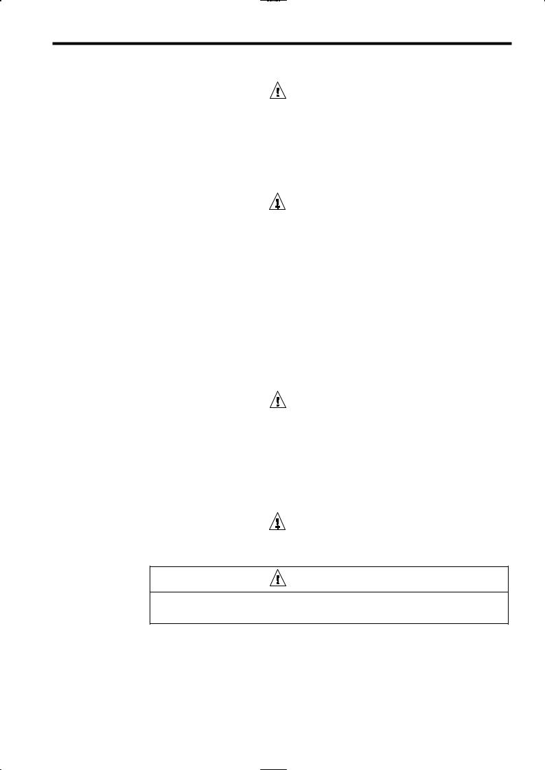
Warning Label Contents and Position
There is a warning label on the Inverter in the position shown in the following illustration. Always heed the warnings given on this label.
Warning label position
Illustration shows the CIMR-G5A23P7
Warning Label Contents
viii
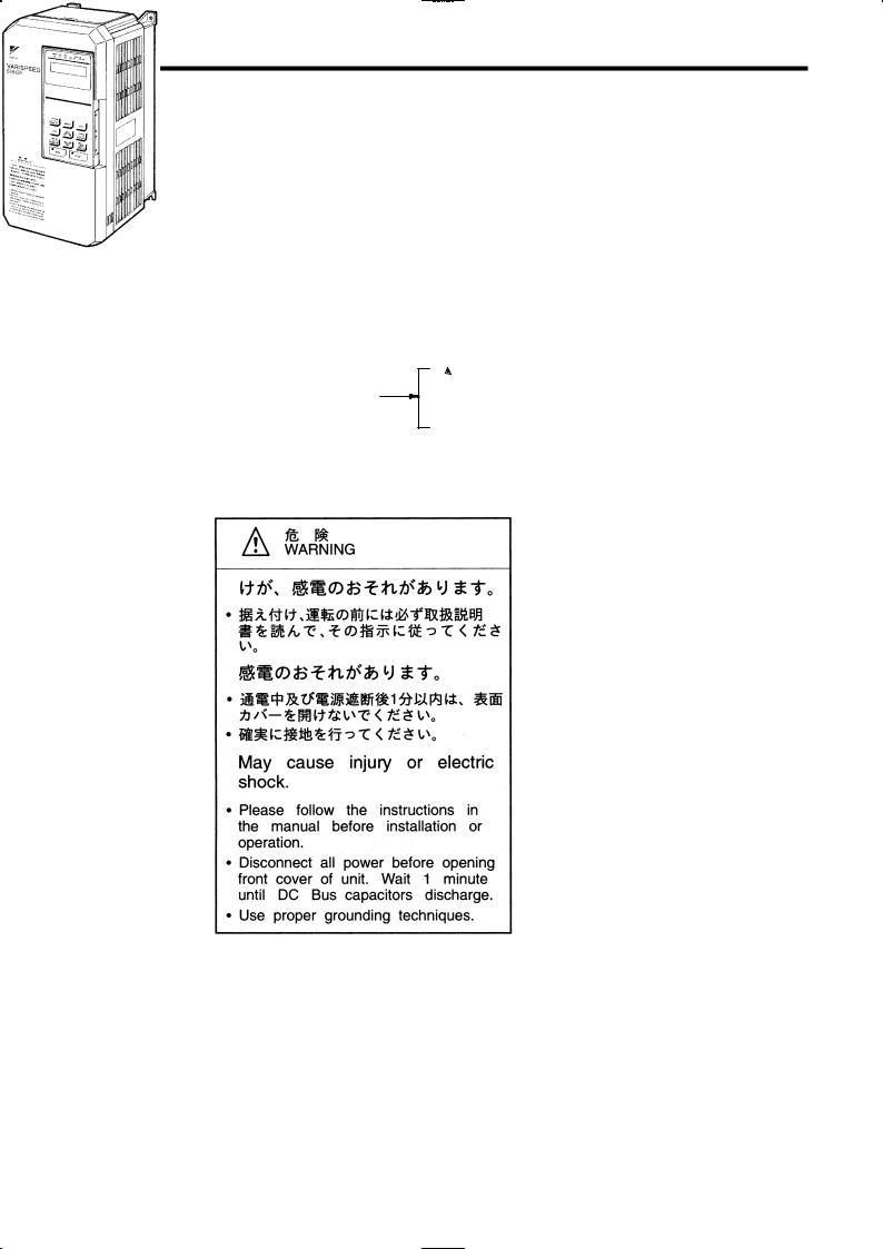
How to Change the Digital Operator Display from Japanese to English
How to Change the Digital Operator Display from Japanese to E
If the Digital Operator displays messages in Japanese, change to the English mode using the following steps.
(This manual provides descriptions for the English mode.)
ix
![]()
Warranty Information
J Free Warranty Period and Scope
Warranty Period
This product is warranted for twelve months after being delivered to Yaskawa’s customer or if applicable eighteen months from the date of shipment from Yaskawa’s factory whichever comes first.
Scope of Warranty Inspections
Periodic inspections must be conducted by the customer. However, upon request, Yaskawa or one of Yaskawa’s Service Centers can inspect the product for a fee. In this case, if after conferring with the customer, a Yaskawa product is found to be defective due to Yaskawa workmanship or materials and the defect occurs during the warranty period, then this fee will be waived and the problem remedied free of charge.
Repairs
If a Yaskawa product is found to be defective due to Yaskawa workmanship or materials and the defect occurs during the warranty period, Yaskawa will provide a replacement, repair the defective product, and provide shipping to and from the site free of charge.
However, if the Yaskawa Authorized Service Center determines that the problem with a Yaskawa product is not due to defects in Yaskawa’s workmanship or materials, then the customer will be responsible for the cost of any necessary repairs. Some problems that are outside the scope of this warranty are:
DProblems due to improper maintenance or handling, carelessness, or other reasons where the customer is determined to be responsible.
DProblems due to additions or modifications made to a Yaskawa product without Yaskawa’s understanding.
DProblems due to the use of a Yaskawa product under conditions that do not meet the recommended specifications.
D Problems caused by natural disaster or fire.
D Or other problems not due to defects in Yaskawa workmanship or materials.
Warranty service is only applicable within Japan.
However, after−sales service is available for customers outside of Japan for a reasonable fee. Contact your local Yaskawa representative for more information.
JExceptions
Any inconvenience to the customer or damage to non−Yaskawa products due to Yaskawa’s defective products whether within or outside the warranty period are NOT covered by this warranty.
x
Before Reading This Manual
J Restrictions
DThe Varispeed F7 was not designed or manufactured for use in devices or systems that may directly affect or threaten human lives or health.
DCustomers who intend to use the product described in this manual for devices or systems relating to transportation, health care, space aviation, atomic or electric power, or underwater use must contact their Yaskawa representatives or the nearest Yaskawa sales office beforehand.
DThis product has been manufactured under strict quality−control guidelines. However, if this product is to be installed in any location where failure of this product could involve or result in a life−and−death situation or loss of human life or in a facility where failure may cause a serious accident or physical injury, safety devices must be installed to minimize the likelihood of any accident.
Before Reading This Manual
This manual explains both the conventional VS-616G5 Inverters and the G5-series Inverters for SPEC:F.
The shaded sections or those specified as being for SPEC:F apply only to G5-series Inverters for SPEC:F ( Inverters with revised version letters of F or later.)
Be certain to check the specification on the Inverter nameplate.
Example of Inverter Nameplate
Version code
MODEL : CIMR−G5A20P4 SPEC: 20P41F
|
INPUT : AC 3PH |
200-220 V |
50Hz |
|
200-230 V |
60Hz |
|
|
OUTPUT: AC 3PH |
0-230 V 1.2kVA 3.2 A |
LOT NO : MASS : 3.0kg
SER NO :
|
YASKAWA ELECTRIC CORPORATION |
JAPAN |
xi

CONTENTS
11 Introduction
12 Handling Inverters
13 Wiring
14 Setting User Constants
15 Trial Operation
16 Basic Operation
17 Advanced Operation
18 User Constants
|
19 |
Troubleshooting |
9 |
|
10 |
Maintenance and Inspection |
10 |
11Specifications
12Appendix
xiii

Table of Contents
|
Table of Contents |
|||||
|
Safety Information . . . . . . . . . . . . . . . . . . . . . . . . . . . . . . . . . . . . . . . . . . . . . . . . . . |
ii |
||||
|
Visual Aids . . . . . . . . . . . . . . . . . . . . . . . . . . . . . . . . . . . . . . . . . . . . . . . . . . . . . . . . |
iii |
||||
|
General Precautions . . . . . . . . . . . . . . . . . . . . . . . . . . . . . . . . . . . . . . . . . . . . . . . . |
iv |
||||
|
Safety Precautions . . . . . . . . . . . . . . . . . . . . . . . . . . . . . . . . . . . . . . . . . . . . . . . . . |
v |
||||
|
Warning Label Contents and Position . . . . . . . . . . . . . . . . . . . . . . . . . . . . . . . . . |
viii |
||||
|
How to Change the Digital Operator Display from Japanese to English . . . . |
ix |
||||
|
Warranty Information . . . . . . . . . . . . . . . . . . . . . . . . . . . . . . . . . . . . . . . . . . . . . . . |
x |
||||
|
Before Reading This Manual . . . . . . . . . . . . . . . . . . . . . . . . . . . . . . . . . . . . . . . . . |
xi |
||||
|
1 |
Introduction. . . . . . . . . . . . . . . . . . . . . . . . . . . . . . . . . . . . . . . . |
1 |
— |
1 |
|
|
1.1 |
Outline and Functions . . . . . . . . . . . . . . . . . . . . . . . . . . . . . . . . . . . . . . . . |
1 — 2 |
|||
|
1.1.1 |
VS-616G5 Inverter Models . . . . . . . . . . . . . . . . . . . . . . . . . . . . . . . . . . . . . . . . . . . . |
1 — 2 |
|||
|
1.1.2 |
Outline of Control Methods . . . . . . . . . . . . . . . . . . . . . . . . . . . . . . . . . . . . . . . . . . . . |
1 — 4 |
|||
|
1.1.3 |
Functions . . . . . . . . . . . . . . . . . . . . . . . . . . . . . . . . . . . . . . . . . . . . . . . . . . . . . . . . . . . |
1 — 4 |
|||
|
1.2 |
Nomenclature . . . . . . . . . . . . . . . . . . . . . . . . . . . . . . . . . . . . . . . . . . . . . . . |
1 — 7 |
|||
|
1.2.1 VS-616G5 Components . . . . . . . . . . . . . . . . . . . . . . . . . . . . . . . . . . . . . . . . . . . . . . . |
1 — 7 |
||||
|
1.2.2 |
Digital Operator Components . . . . . . . . . . . . . . . . . . . . . . . . . . . . . . . . . . . . . . . . . . |
1 — 8 |
|||
|
2 |
Handling Inverters. . . . . . . . . . . . . . . . . . . . . . . . . . . . . . . . . . |
2 |
— |
1 |
|
|
2.1 |
Confirmations upon Delivery . . . . . . . . . . . . . . . . . . . . . . . . . . . . . . . . . . |
2 — 2 |
|||
|
2.1.1 |
Nameplate Information . . . . . . . . . . . . . . . . . . . . . . . . . . . . . . . . . . . . . . . . . . . . . . . . |
2 — 2 |
|||
|
2.2 |
Exterior and Mounting Dimensions . . . . . . . . . . . . . . . . . . . . . . . . . . . . . |
2 — 4 |
|||
|
2.3 |
Checking and Controlling the Installation Site . . . . . . . . . . . . . . . . . . . |
2 — 6 |
|||
|
2.3.1 |
Installation Site . . . . . . . . . . . . . . . . . . . . . . . . . . . . . . . . . . . . . . . . . . . . . . . . . . . . . . |
2 — 6 |
|||
|
2.3.2 |
Controlling the Ambient Temperature . . . . . . . . . . . . . . . . . . . . . . . . . . . . . . . . . . . |
2 — 6 |
|||
|
2.3.3 |
Protecting the Inverter from Foreign Matter . . . . . . . . . . . . . . . . . . . . . . . . . . . . . . |
2 — 6 |
|||
|
2.4 |
Installation Orientation and Space . . . . . . . . . . . . . . . . . . . . . . . . . . . . . |
2 — 7 |
|||
|
2.5 |
Removing/Attaching the Digital Operator and Front Cover . . . . . . . . |
2 — 8 |
|||
|
2.5.1 |
Inverters of 15 kW or Less . . . . . . . . . . . . . . . . . . . . . . . . . . . . . . . . . . . . . . . . . . . . |
2 — 8 |
|||
|
2.5.2 |
Inverters of 18.5 kW or Higher . . . . . . . . . . . . . . . . . . . . . . . . . . . . . . . . . . . . . . . . . |
2 — 9 |
|||
|
3 |
Wiring . . . . . . . . . . . . . . . . . . . . . . . . . . . . . . . . . . . . . . . . . . . . . |
3 |
— |
1 |
|
|
3.1 |
Connections to Peripheral Devices . . . . . . . . . . . . . . . . . . . . . . . . . . . . |
3 — 3 |
|||
|
3.2 |
Connection Diagram . . . . . . . . . . . . . . . . . . . . . . . . . . . . . . . . . . . . . . . . . |
3 — 4 |
|||
|
3.3 |
Terminal Block Configuration . . . . . . . . . . . . . . . . . . . . . . . . . . . . . . . . . . |
3 — 5 |
|||
|
3.4 |
Wiring Main Circuit Terminals . . . . . . . . . . . . . . . . . . . . . . . . . . . . . . . . . |
3 — 6 |
|||
|
3.4.1 |
Applicable Wire Sizes and Closed-loop Connectors . . . . . . . . . . . . . . . . . . . . . . . |
3 — 6 |
|||
|
3.4.2 |
Main Circuit Terminal Functions . . . . . . . . . . . . . . . . . . . . . . . . . . . . . . . . . . . . . . . . |
3 — 9 |
|||
|
3.4.3 |
Main Circuit Configurations . . . . . . . . . . . . . . . . . . . . . . . . . . . . . . . . . . . . . . . . . . . . |
3 — 10 |
|||
|
3.4.4 |
Standard Connection Diagrams . . . . . . . . . . . . . . . . . . . . . . . . . . . . . . . . . . . . . . . . |
3 — 12 |
|||
|
3.4.5 |
Wiring the Main Circuits . . . . . . . . . . . . . . . . . . . . . . . . . . . . . . . . . . . . . . . . . . . . . . . |
3 — 13 |
xv

|
3.5 |
Wiring Control Circuit Terminals . . . . . . . . . . . . . . . . . . . . . . . . . . . . . . . |
3 — 20 |
|
|
3.5.1 |
Wire Sizes and Closed-loop Connectors . . . . . . . . . . . . . . . . . . . . . . . . . . . . . . . . |
3 — 20 |
|
|
3.5.2 |
Control Circuit Terminal Functions . . . . . . . . . . . . . . . . . . . . . . . . . . . . . . . . . . . . . . |
3 — 21 |
|
|
3.5.3 |
Control Circuit Terminal Connections (All Models) . . . . . . . . . . . . . . . . . . . . . . . . |
3 — 22 |
|
|
3.5.4 |
Control Circuit Wiring Precautions . . . . . . . . . . . . . . . . . . . . . . . . . . . . . . . . . . . . . . |
3 — 23 |
|
|
3.6 |
Wiring Check . . . . . . . . . . . . . . . . . . . . . . . . . . . . . . . . . . . . . . . . . . . . . . . |
3 — 23 |
|
|
3.7 |
Installing and Wiring PG Speed Control Cards . . . . . . . . . . . . . . . . . . |
3 — 24 |
|
|
3.7.1 |
Installing a PG Speed Control Card . . . . . . . . . . . . . . . . . . . . . . . . . . . . . . . . . . . . . |
3 — 24 |
|
|
3.7.2 |
PG Speed Control Card Terminal Blocks . . . . . . . . . . . . . . . . . . . . . . . . . . . . . . . . |
3 — 25 |
|
|
3.7.3 |
Wiring a PG Speed Control Card . . . . . . . . . . . . . . . . . . . . . . . . . . . . . . . . . . . . . . . |
3 — 27 |
|
|
3.7.4 |
Wiring PG Speed Control Card Terminal Blocks . . . . . . . . . . . . . . . . . . . . . . . . . . |
3 — 31 |
|
|
3.7.5 |
Selecting the Number of PG (Encoder) Pulses . . . . . . . . . . . . . . . . . . . . . . . . . . . |
3 — 33 |
|
4 |
Setting |
User |
Constants. . . . . . . . . . . . . . . . . . . . . . . . . . . . . . |
4 |
— |
1 |
|
|
4.1 |
Using the Digital Operator . . . . . . . . . . . . . . . . . . . . . . . . . . . . . . . . . . . . |
4 — 2 |
|||||
|
4.2 |
Modes. . |
. . . . . . . . |
. . . . . . . . . . . . . . . . . . . . . . . . . . . . . . . . . . . . . . . . . . . |
4 — |
5 |
||
|
4.2.1 |
Inverter Modes . . |
. . . . . . . . . . . . . . . . . . . . . . . . . . . . . . . . . . . . . . . . . . . . . . . . . . . . |
4 — 5 |
||||
|
4.2.2 |
Switching Modes . |
. . . . . . . . . . . . . . . . . . . . . . . . . . . . . . . . . . . . . . . . . . . . . . . . . . . . |
4 — 6 |
||||
|
4.2.3 |
User |
Constant |
Access Levels. . . . . . . . . . . . . . . . . . . . . . . . . . . . . . . . . . . . . . . . . . |
4 |
— |
7 |
|
|
4.2.4 |
Operation Mode . |
. . . . . . . . . . . . . . . . . . . . . . . . . . . . . . . . . . . . . . . . . . . . . . . . . . . . |
4 — 12 |
||||
|
4.2.5 |
Initialize Mode . . . |
. . . . . . . . . . . . . . . . . . . . . . . . . . . . . . . . . . . . . . . . . . . . . . . . . . . . |
4 — 20 |
||||
|
4.2.6 Programming Mode . . . . . . . . . . . . . . . . . . . . . . . . . . . . . . . . . . . . . . . . . . . . . . . . . . |
4 — 27 |
||||||
|
4.2.7 |
Autotuning Mode . |
. . . . . . . . . . . . . . . . . . . . . . . . . . . . . . . . . . . . . . . . . . . . . . . . . . . . |
4 — 31 |
||||
|
4.2.8 |
Modified Constants Mode . . . . . . . . . . . . . . . . . . . . . . . . . . . . . . . . . . . . . . . . . . . . . |
4 — 33 |
|
5 |
Trial Operation. . . . . . . . . . . . . . . . . . . . . . . . . . . . . . . . . . . . . . |
5 |
— |
1 |
|
|
5.1 |
Procedure . . . . . . . . . . . . . . . . . . . . . . . . . . . . . . . . . . . . . . . . . . . . . . . . . . |
5 — 3 |
|||
|
5.2 |
Trial Operation Procedures . . . . . . . . . . . . . . . . . . . . . . . . . . . . . . . . . . . |
5 — 4 |
|||
|
5.2.1 Power ON . . . . . . . . . . . . . . . . . . . . . . . . . . . . . . . . . . . . . . . . . . . . . . . . . . . . . . . . . . . |
5 — 4 |
||||
|
5.2.2 |
Checking the Display Status. . . . . . . . . . . . . . . . . . . . . . . . . . . . . . . . . . . . . . . . . . . |
5 |
— |
4 |
|
|
5.2.3 |
Initializing Constants . . . . . . . . . . . . . . . . . . . . . . . . . . . . . . . . . . . . . . . . . . . . . . . . . |
5 — 4 |
|||
|
5.2.4 |
Setting Input Voltage . . . . . . . . . . . . . . . . . . . . . . . . . . . . . . . . . . . . . . . . . . . . . . . . . |
5 — 5 |
|||
|
5.2.5 |
Autotuning . . . . . . . . . . . . . . . . . . . . . . . . . . . . . . . . . . . . . . . . . . . . . . . . . . . . . . . . . . |
5 — 6 |
|||
|
5.2.6 |
No-load Operation . . . . . . . . . . . . . . . . . . . . . . . . . . . . . . . . . . . . . . . . . . . . . . . . . . . |
5 — 9 |
|||
|
5.2.7 |
Loaded Operation . . . . . . . . . . . . . . . . . . . . . . . . . . . . . . . . . . . . . . . . . . . . . . . . . . . . |
5 — 10 |
|
6 |
Basic Operation. . . . . . . . . . . . . . . . . . . . . . . . . . . . . . . . . . . . |
6 — 1 |
|
|
6.1 Common Settings . . . . . . . . . . . . . . . . . . . . . . . . . . . . . . . . . . . . . . . . . . . |
6 — 2 |
||
|
6.1.1 |
Setting the Access Level and Control Method: A1-01, A1-02 . . . . . . . . . . . . . . . |
6 — 2 |
|
|
6.1.2 |
Frequency Reference Settings: b1-01, H3-01, H3-08, H3-09 . . . . . . . . . . . . . . . |
6 — 4 |
|
|
6.1.3 |
Frequency Reference from Digital Operator: b1-01, o1-03, d1-01 to d1-09 . . . |
6 — 7 |
|
|
6.1.4 |
Run Source and Sequence Input Responsiveness: b1-02, b1-06, b1-07 . . . . . |
6 — 9 |
|
|
6.1.5 |
Acceleration/Deceleration Times: C1-01 through C1-08, C1-09, C1-10, C1-11 |
6 — 10 |
|
|
6.1.6 |
Prohibiting Reverse Operation: b1-04 . . . . . . . . . . . . . . . . . . . . . . . . . . . . . . . . . . . |
6 — 11 |
|
|
6.1.7 |
Selecting the Stopping Method: b1-03 . . . . . . . . . . . . . . . . . . . . . . . . . . . . . . . . . . |
6 — 12 |
|
|
6.1.8 |
Multi-function Input Settings: H1-01 through H1-06 . . . . . . . . . . . . . . . . . . . . . . . |
6 — 13 |
|
|
6.2 |
Open-loop Vector Control . . . . . . . . . . . . . . . . . . . . . . . . . . . . . . . . . . . . . |
6 — 18 |
|
|
6.2.1 |
Autotuning . . . . . . . . . . . . . . . . . . . . . . . . . . . . . . . . . . . . . . . . . . . . . . . . . . . . . . . . . . |
6 — 18 |
|
|
6.2.2 |
Autotuning Faults . . . . . . . . . . . . . . . . . . . . . . . . . . . . . . . . . . . . . . . . . . . . . . . . . . . . |
6 — 19 |
|
|
6.3 |
V/f Control . . . . . . . . . . . . . . . . . . . . . . . . . . . . . . . . . . . . . . . . . . . . . . . . . . |
6 — 21 |
|
|
6.3.1 |
Setting the Motor Constants: E1-01, E1-02, E2-01 . . . . . . . . . . . . . . . . . . . . . . . . |
6 — 21 |
|
|
6.3.2 |
V/f Pattern Selection: E1-03 . . . . . . . . . . . . . . . . . . . . . . . . . . . . . . . . . . . . . . . . . . . |
6 — 22 |
xvi

Table of Contents
|
6.4 Flux Vector Control . . . . . . . . . . . . . . . . . . . . . . . . . . . . . . . . . . . . . . . . . . |
6 — 28 |
|
|
6.4.1 |
PG Speed Control Card Settings . . . . . . . . . . . . . . . . . . . . . . . . . . . . . . . . . . . . . . . |
6 — 28 |
|
6.4.2 |
Setting the Zero-speed Operation Constants . . . . . . . . . . . . . . . . . . . . . . . . . . . . . |
6 — 31 |
|
6.4.3 |
Autotuning . . . . . . . . . . . . . . . . . . . . . . . . . . . . . . . . . . . . . . . . . . . . . . . . . . . . . . . . . . |
6 — 33 |
|
6.4.4 |
Speed Control (ASR) Structure . . . . . . . . . . . . . . . . . . . . . . . . . . . . . . . . . . . . . . . . |
6 — 36 |
|
6.4.5 |
Speed Control (ASR) Gain . . . . . . . . . . . . . . . . . . . . . . . . . . . . . . . . . . . . . . . . . . . . |
6 — 38 |
|
6.5 V/f Control with PG . . . . . . . . . . . . . . . . . . . . . . . . . . . . . . . . . . . . . . . . . . |
6 — 40 |
|
|
6.5.1 |
Motor Constants: E1-01, E1-02, E2-01, E2-04. . . . . . . . . . . . . . . . . . . . . . . . . . |
6 — 40 |
|
6.5.2 |
V/f Pattern Selection: E1-03 . . . . . . . . . . . . . . . . . . . . . . . . . . . . . . . . . . . . . . . . . . . |
6 — 41 |
|
6.5.3 |
PG Speed Control Card Settings . . . . . . . . . . . . . . . . . . . . . . . . . . . . . . . . . . . . . . . |
6 — 42 |
|
6.5.4 |
Speed Control (ASR) Structure . . . . . . . . . . . . . . . . . . . . . . . . . . . . . . . . . . . . . . . . |
6 — 44 |
|
6.5.5 |
Adjusting Speed Control (ASR) Gain . . . . . . . . . . . . . . . . . . . . . . . . . . . . . . . . . . . . |
6 — 45 |
|
7 |
Advanced Operation. . . . . . . . . . . . . . . . . . . . . . . . . . . . . . . . |
7 — 1 |
|
|
7.1 |
Open-loop Vector Control . . . . . . . . . . . . . . . . . . . . . . . . . . . . . . . . . . . . . |
7 — 2 |
|
|
7.1.1 |
Torque Limit Function . . . . . . . . . . . . . . . . . . . . . . . . . . . . . . . . . . . . . . . . . . . . . . . . . |
7 — 4 |
|
|
7.1.2 |
Adjusting Speed Feedback . . . . . . . . . . . . . . . . . . . . . . . . . . . . . . . . . . . . . . . . . . . . |
7 — 5 |
|
|
7.1.3 |
Setting/Adjusting Motor Constants . . . . . . . . . . . . . . . . . . . . . . . . . . . . . . . . . . . . . . |
7 — 6 |
|
|
7.1.4 |
Operation Selection when Output Voltage Saturated . . . . . . . . . . . . . . . . . . . . . . |
7 — 8 |
|
|
7.1.5 |
Starting Torque Compensation Function (for SPEC:F) . . . . . . . . . . . . . . . . . . . . . |
7 — 9 |
|
|
7.2 |
V/f Control without PG . . . . . . . . . . . . . . . . . . . . . . . . . . . . . . . . . . . . . . . |
7 — 11 |
|
|
7.2.1 |
Energy-saving Control Function . . . . . . . . . . . . . . . . . . . . . . . . . . . . . . . . . . . . . . . . |
7 — 13 |
|
|
7.2.2 |
Hunting-prevention Function . . . . . . . . . . . . . . . . . . . . . . . . . . . . . . . . . . . . . . . . . . . |
7 — 13 |
|
|
7.2.3 |
Setting Motor Constants . . . . . . . . . . . . . . . . . . . . . . . . . . . . . . . . . . . . . . . . . . . . . . |
7 — 14 |
|
|
7.3 |
Flux Vector Control . . . . . . . . . . . . . . . . . . . . . . . . . . . . . . . . . . . . . . . . . . |
7 — 16 |
|
|
7.3.1 |
Droop Control Function . . . . . . . . . . . . . . . . . . . . . . . . . . . . . . . . . . . . . . . . . . . . . . . |
7 — 18 |
|
|
7.3.2 |
Zero-servo Function . . . . . . . . . . . . . . . . . . . . . . . . . . . . . . . . . . . . . . . . . . . . . . . . . . |
7 — 19 |
|
|
7.3.3 |
Torque Control . . . . . . . . . . . . . . . . . . . . . . . . . . . . . . . . . . . . . . . . . . . . . . . . . . . . . . . |
7 — 21 |
|
|
7.3.4 |
Speed/Torque Control Switching Function . . . . . . . . . . . . . . . . . . . . . . . . . . . . . . . |
7 — 27 |
|
|
7.3.5 |
Torque Limit Function . . . . . . . . . . . . . . . . . . . . . . . . . . . . . . . . . . . . . . . . . . . . . . . . . |
7 — 30 |
|
|
7.3.6 |
Setting/Adjusting Motor Constants . . . . . . . . . . . . . . . . . . . . . . . . . . . . . . . . . . . . . . |
7 — 31 |
|
|
7.3.7 |
Operation Selection when Output Voltage Saturated . . . . . . . . . . . . . . . . . . . . . . |
7 — 34 |
|
|
7.4 |
V/f Control with PG . . . . . . . . . . . . . . . . . . . . . . . . . . . . . . . . . . . . . . . . . . |
7 — 36 |
|
|
7.4.1 Energy-saving Control Function . . . . . . . . . . . . . . . . . . . . . . . . . . . . . . . . . . . . . . . . |
7 — 38 |
||
|
7.4.2 Hunting-prevention Function . . . . . . . . . . . . . . . . . . . . . . . . . . . . . . . . . . . . . . . . . . . |
7 — 38 |
||
|
7.4.3 Setting Motor Constants . . . . . . . . . . . . . . . . . . . . . . . . . . . . . . . . . . . . . . . . . . . . . . . |
7 — 39 |
||
|
7.5 Common Functions . . . . . . . . . . . . . . . . . . . . . . . . . . . . . . . . . . . . . . . . . . |
7 — 41 |
||
|
7.5.1 |
Application Constants: b . . . . . . . . . . . . . . . . . . . . . . . . . . . . . . . . . . . . . . . . . . . . . . |
7 — 43 |
|
|
7.5.2 |
Tuning Constants: C . . . . . . . . . . . . . . . . . . . . . . . . . . . . . . . . . . . . . . . . . . . . . . . . . . |
7 — 52 |
|
|
7.5.3 |
Reference Constants: d . . . . . . . . . . . . . . . . . . . . . . . . . . . . . . . . . . . . . . . . . . . . . . . |
7 — 57 |
|
|
7.5.4 |
Option Constants: F . . . . . . . . . . . . . . . . . . . . . . . . . . . . . . . . . . . . . . . . . . . . . . . . . . |
7 — 59 |
|
|
7.5.5 |
External Terminal Functions: H . . . . . . . . . . . . . . . . . . . . . . . . . . . . . . . . . . . . . . . . . |
7 — 64 |
|
|
7.5.6 |
Protective Functions: L . . . . . . . . . . . . . . . . . . . . . . . . . . . . . . . . . . . . . . . . . . . . . . . |
7 — 84 |
|
|
7.5.7 |
Operator Constants: o . . . . . . . . . . . . . . . . . . . . . . . . . . . . . . . . . . . . . . . . . . . . . . . . |
7 — 97 |
|
8 |
User Constants. . . . . . . . . . . . . . . . . . . . . . . . . . . . . . . . . . . . . |
8 — 1 |
|
|
8.1 |
Initialize Mode Constants . . . . . . . . . . . . . . . . . . . . . . . . . . . . . . . . . . . . . |
8 — 3 |
|
|
8.2 |
Programming Mode Constants . . . . . . . . . . . . . . . . . . . . . . . . . . . . . . . . |
8 — 5 |
|
|
8.2.1 |
Application Constants: b . . . . . . . . . . . . . . . . . . . . . . . . . . . . . . . . . . . . . . . . . . . . . . |
8 — 5 |
|
|
8.2.2 |
Autotuning Constants: C . . . . . . . . . . . . . . . . . . . . . . . . . . . . . . . . . . . . . . . . . . . . . . |
8 — 11 |
|
|
8.2.3 |
Reference Constants: d . . . . . . . . . . . . . . . . . . . . . . . . . . . . . . . . . . . . . . . . . . . . . . . |
8 — 17 |
|
|
8.2.4 |
Motor Constant Constants: E . . . . . . . . . . . . . . . . . . . . . . . . . . . . . . . . . . . . . . . . . . |
8 — 20 |
|
|
8.2.5 |
Options Constants: F . . . . . . . . . . . . . . . . . . . . . . . . . . . . . . . . . . . . . . . . . . . . . . . . . |
8 — 24 |
xvii

|
8.2.6 |
Terminal Constants: H . . . . . . . . . . . . . . . . . . . . . . . . . . . . . . . . . . . . . . . . . . . . . . . . |
8 — 28 |
||
|
8.2.7 |
Protection Constants: L . . . . . . . . . . . . . . . . . . . . . . . . . . . . . . . . . . . . . . . . . . . . . . . |
8 — 35 |
||
|
8.2.8 |
Operator Constants: o . . . . . . . . . . . . . . . . . . . . . . . . . . . . . . . . . . . . . . . . . . . . . . . . |
8 — 43 |
||
|
8.2.9 |
Factory Settings that Change with the Control Method (A1-02) . . . . . . . . . . . . . |
8 — 45 |
||
|
8.2.10 |
Factory Settings that Change with the Inverter Capacity (o2-04) . . . . . . . . . . . |
8 — 47 |
||
|
9 |
Troubleshooting. . . . . . . . . . . . . . . . . . . . . . . . . . . . . . . . . . . . |
9 — |
1 |
|
|
9.1 |
Protective and Diagnostic Functions . . . . . . . . . . . . . . . . . . . . . . . . . . . |
9 — 2 |
||
|
9.1.1 |
Fault Detection . . . . . . . . . . . . . . . . . . . . . . . . . . . . . . . . . . . . . . . . . . . . . . . . . . . . . . |
9 — 2 |
||
|
9.1.2 |
Minor Fault Detection . . . . . . . . . . . . . . . . . . . . . . . . . . . . . . . . . . . . . . . . . . . . . . . . . |
9 — 6 |
||
|
9.1.3 |
Operation Errors . . . . . . . . . . . . . . . . . . . . . . . . . . . . . . . . . . . . . . . . . . . . . . . . . . . . . |
9 — 8 |
||
|
9.2 |
Troubleshooting . . . . . . . . . . . . . . . . . . . . . . . . . . . . . . . . . . . . . . . . . . . . . |
9 — 9 |
||
|
9.2.1 |
If Constant Constants Cannot Be Set . . . . . . . . . . . . . . . . . . . . . . . . . . . . . . . . . . . |
9 — 9 |
||
|
9.2.2 |
If the Motor Does Not Operate . . . . . . . . . . . . . . . . . . . . . . . . . . . . . . . . . . . . . . . . . |
9 — 9 |
||
|
9.2.3 |
If the Direction of the Motor Rotation is Reversed . . . . . . . . . . . . . . . . . . . . . . . . . |
9 — 11 |
||
|
9.2.4 |
If the Motor Does Not Put Out Torque or If Acceleration is Slow . . . . . . . . . . . . . |
9 — 11 |
||
|
9.2.5 |
If the Motor Does Not Operate According to Reference . . . . . . . . . . . . . . . . . . . . |
9 — 11 |
||
|
9.2.6 |
If the Slip Compensation Function Has Low Speed Precision . . . . . . . . . . . . . . . |
9 — 11 |
||
|
9.2.7 |
If There is Low Speed Control Accuracy at High-speed Rotation in Open-loop |
|||
|
Vector Control Mode . . . . . . . . . . . . . . . . . . . . . . . . . . . . . . . . . . . . . . . . . . . . . . . . |
9 — 11 |
|||
|
9.2.8 |
If Motor Deceleration is Slow . . . . . . . . . . . . . . . . . . . . . . . . . . . . . . . . . . . . . . . . . . |
9 — 12 |
||
|
9.2.9 |
If the Motor Overheats . . . . . . . . . . . . . . . . . . . . . . . . . . . . . . . . . . . . . . . . . . . . . . . . |
9 — 12 |
||
|
9.2.10 |
If There is Noise When the Inverter is Started or From an AM Radio . . . . . . . |
9 — 13 |
||
|
9.2.11 |
If the Ground Fault Interrupter Operates When the Inverter is Run . . . . . . . . . |
9 — 13 |
||
|
9.2.12 |
If There is Mechanical Oscillation . . . . . . . . . . . . . . . . . . . . . . . . . . . . . . . . . . . . . |
9 — 13 |
||
|
9.2.13 |
If the Motor Rotates Even When Inverter Output is Stopped . . . . . . . . . . . . . . . |
9 — 14 |
||
|
9.2.14 |
If 0 V is Detected When the Fan is Started, or Fan Stalls . . . . . . . . . . . . . . . . . |
9 — 14 |
||
|
9.2.15 |
If Output Frequency Does Not Rise to Frequency Reference . . . . . . . . . . . . . . |
9 — 14 |
||
|
10 |
Maintenance and Inspection. . . . . . . . . . . . . . . . . . . . . . . . . |
10 |
— 1 |
10.1 Maintenance and Inspection . . . . . . . . . . . . . . . . . . . . . . . . . . . . . . . . . 10 — 3
10.1.1 Daily Inspection . . . . . . . . . . . . . . . . . . . . . . . . . . . . . . . . . . . . . . . . . . . . . . . . . . . . 10 — 3
10.1.2 Periodic Inspection . . . . . . . . . . . . . . . . . . . . . . . . . . . . . . . . . . . . . . . . . . . . . . . . . . 10 — 3
10.1.3 Periodic Maintenance of Parts . . . . . . . . . . . . . . . . . . . . . . . . . . . . . . . . . . . . . . . . 10 — 3
11 Specifications. . . . . . . . . . . . . . . . . . . . . . . . . . . . . . . . . . . . . . 11 — 1
11.1 Standard Inverter Specifications . . . . . . . . . . . . . . . . . . . . . . . . . . . . . . 11 — 2 11.2 Specifications of Options and Peripheral Devices . . . . . . . . . . . . . . . 11 — 5
12 Appendix. . . . . . . . . . . . . . . . . . . . . . . . . . . . . . . . . . . . . . . . . . . 12 — 1
|
12.1 Inverter Application Precautions . . . . . . . . . . . . . . . . . . . . . . . . . . . . . . |
12 — 2 |
|
|
12.1.1 |
Selection . . . . . . . . . . . . . . . . . . . . . . . . . . . . . . . . . . . . . . . . . . . . . . . . . . . . . . . . . . |
12 — 2 |
|
12.1.2 |
Installation . . . . . . . . . . . . . . . . . . . . . . . . . . . . . . . . . . . . . . . . . . . . . . . . . . . . . . . . |
12 — 2 |
|
12.1.3 |
Settings . . . . . . . . . . . . . . . . . . . . . . . . . . . . . . . . . . . . . . . . . . . . . . . . . . . . . . . . . . . |
12 — 3 |
|
12.1.4 |
Handling . . . . . . . . . . . . . . . . . . . . . . . . . . . . . . . . . . . . . . . . . . . . . . . . . . . . . . . . . . |
12 — 3 |
|
12.2 Motor Application Precautions . . . . . . . . . . . . . . . . . . . . . . . . . . . . . . . |
12 — 4 |
|
|
12.2.1 Using the Inverter for an Existing Standard Motor . . . . . . . . . . . . . . . . . . . . . . . |
12 — 4 |
|
|
12.2.2 |
Using the Inverter for Special Motors . . . . . . . . . . . . . . . . . . . . . . . . . . . . . . . . . |
12 — 5 |
|
12.2.3 |
Power Transmission Mechanism (Speed Reducers, Belts, and Chains) . . . . |
12 — 5 |
|
12.3 Peripheral Device Application Precautions . . . . . . . . . . . . . . . . . . . . . |
12 — 6 |
xviii

Table of Contents
|
12.4 Wiring Examples . . . . . . . . . . . . . . . . . . . . . . . . . . . . . . . . . . . . . . . . . . . |
12 — 8 |
|
12.4.1 Using a Braking Resistor Unit . . . . . . . . . . . . . . . . . . . . . . . . . . . . . . . . . . . . . . . . . |
12 — 8 |
|
12.4.2 Using a Braking Unit and Braking Resistor Unit . . . . . . . . . . . . . . . . . . . . . . . . . . |
12 — 8 |
|
12.4.3 Using Braking Units in Parallel . . . . . . . . . . . . . . . . . . . . . . . . . . . . . . . . . . . . . . . . |
12 — 11 |
|
12.4.4 Using a Braking Unit and Three Braking Resistor Units in Parallel . . . . . . . . . . |
12 — 12 |
|
12.4.5 Using a JVOP-95-j, -96-j VS Operator . . . . . . . . . . . . . . . . . . . . . . . . . . . . . . . |
12 — 13 |
|
12.4.6 Using an Open-collector Transistor for Operation Signals . . . . . . . . . . . . . . . . . |
12 — 14 |
|
12.4.7 Using Open-collector, Contact Outputs . . . . . . . . . . . . . . . . . . . . . . . . . . . . . . . . . |
12 — 14 |
12.5 User Constants . . . . . . . . . . . . . . . . . . . . . . . . . . . . . . . . . . . . . . . . . . . . 12 — 15
12.6 Function Block Diagram . . . . . . . . . . . . . . . . . . . . . . . . . . . . . . . . . . . . . 12 — 20
INDEX
xix

1
1
Introduction
This chapter provides an overview of the VS-616G5 Inverter and describes its functions and components.
|
1.1 Outline and Functions . . . . . . . . . . . . . . . . . . |
1 — 2 |
|
|
1.1.1 |
VS-616G5 Inverter Models . . . . . . . . . . . . . . . . . . . . |
1 — 2 |
|
1.1.2 |
Outline of Control Methods . . . . . . . . . . . . . . . . . . . |
1 — 4 |
|
1.1.3 |
Functions . . . . . . . . . . . . . . . . . . . . . . . . . . . . . . . . . . |
1 — 4 |
|
1.2 Nomenclature . . . . . . . . . . . . . . . . . . . . . . . . . |
1 — 7 |
|
|
1.2.1 |
VS-616G5 Components . . . . . . . . . . . . . . . . . . . . . . |
1 — 7 |
|
1.2.2 |
Digital Operator Components . . . . . . . . . . . . . . . . . |
1 — 8 |
1 — 1

Introduction
1.1.1VS-616G5 Inverter Models
1.1Outline and Functions
The VS-616G5 Inverters provides full-current vector control based on advanced control logic. An autotuning function is included for easy vector control.
The Digital Operator provides a liquid crystal display that is 2 lines by 16 characters in size. User constant settings and monitor items are easily read in interactive operations in either Japanese or English. (The display language can be changed by setting a user constant.)
|
1 |
1.1.1 VS-616G5 Inverter Models |
|
|
VS-616G5 Inverters are available in 200 and 400 V class models. These are listed in the following table. |
||
|
A total of 37 models is available for motor capacities of 0.4 to 300 kW. |
|
Table 1.1 |
VS-616G5 Inverter Models |
||||
|
VS-616G5 |
Inverter Specifications |
||||
|
Maximum |
(Specify all required standards when ordering.) |
||||
|
Voltage |
|||||
|
Applicable |
Open Chassis Type |
Enclosed Wall-mounted |
|||
|
Class |
Motor Out- |
Output Ca- |
Model Number |
Type |
|
|
put [kW] |
pacity [kVA] |
(IEC IP 00) |
(IEC IP 20, NEMA 1) |
||
|
CIMR-G5Ajjjjjj |
CIMR-G5Ajjjjjj |
||||
|
0.4 |
1.2 |
CIMR-G5A20P4 |
20P41j * |
||
|
0.75 |
2.3 |
CIMR-G5A20P7 |
20P71j * |
||
|
1.5 |
3.0 |
CIMR-G5A21P5 |
21P51j * |
||
|
2.2 |
4.2 |
CIMR-G5A22P2 |
Remove the top and bottom |
22P21j * |
|
|
covers from the models |
|||||
|
3.7 |
6.7 |
CIMR-G5A23P7 |
23P71j * |
||
|
listed at the right. |
|||||
|
5.5 |
9.5 |
CIMR-G5A25P5 |
* |
25P51j * |
|
|
7.5 |
13 |
CIMR-G5A27P5 |
27P51j * |
||
|
200 V class |
11 |
19 |
CIMR-G5A2011 |
20111j * |
|
|
15 |
24 |
CIMR-G5A2015 |
20151j * |
||
|
18.5 |
30 |
CIMR-G5A2018 |
20180j * |
20181j ‡ |
|
|
22 |
37 |
CIMR-G5A2022 |
20220j * |
20221j ‡ |
|
|
30 |
50 |
CIMR-G5A2030 |
20300j † |
20301j ‡ |
|
|
37 |
61 |
CIMR-G5A2037 |
20370j † |
20371j ‡ |
|
|
45 |
70 |
CIMR-G5A2045 |
20450j † |
20451j ‡ |
|
|
55 |
85 |
CIMR-G5A2055 |
20550j † |
20551j ‡ |
|
|
75 |
110 |
CIMR-G5A2075 |
20750j ‡ |
20751j ‡ |
|
1 — 2
![]()
1.1 Outline and Functions
|
VS-616G5 |
Inverter Specifications |
||||||||
|
Maximum |
(Specify all required standards when ordering.) |
||||||||
|
Voltage |
|||||||||
|
Applicable |
Open Chassis Type |
Enclosed Wall-mounted |
|||||||
|
Class |
Motor Out- |
Output Ca- |
|||||||
|
Model Number |
Type |
||||||||
|
put [kW] |
(IEC IP 00) |
||||||||
|
pacity [kVA] |
(IEC IP 20, NEMA 1) |
||||||||
|
CIMR-G5Ajjjjjj |
|||||||||
|
CIMR-G5Ajjjjjj |
|||||||||
|
0.4 |
1.4 |
CIMR-G5A40P4 |
40P41j * |
||||||
|
0.75 |
2.6 |
CIMR-G5A40P7 |
40P71j * |
||||||
|
1.5 |
3.7 |
CIMR-G5A41P5 |
41P51j * |
||||||
|
1 |
|||||||||
|
2.2 |
4.7 |
CIMR-G5A42P2 |
Remove the top and bottom |
42P21j * |
|||||
|
covers from the models |
|||||||||
|
3.7 |
6.1 |
CIMR-G5A43P7 |
43P71j * |
||||||
|
listed at the right. |
|||||||||
|
5.5 |
11 |
CIMR-G5A45P5 |
* |
45P51j * |
|||||
|
7.5 |
14 |
CIMR-G5A47P5 |
47P51j * |
||||||
|
11 |
21 |
CIMR-G5A4011 |
40111j * |
||||||
|
15 |
26 |
CIMR-G5A4015 |
40151j * |
||||||
|
18.5 |
31 |
CIMR-G5A4018 |
40180j * |
40181j ‡ |
|||||
|
400 V class |
22 |
37 |
CIMR-G5A4022 |
40220j * |
40221j ‡ |
||||
|
30 |
50 |
CIMR-G5A4030 |
40300j * |
40301j ‡ |
|||||
|
37 |
61 |
CIMR-G5A4037 |
40370j * |
40371j ‡ |
|||||
|
45 |
73 |
CIMR-G5A4045 |
40450j * |
40451j ‡ |
|||||
|
55 |
98 |
CIMR-G5A4055 |
40550j † |
40551j ‡ |
|||||
|
75 |
130 |
CIMR-G5A4075 |
40750j † |
40751j ‡ |
|||||
|
110 |
170 |
CIMR-G5A4110 |
41100j † |
41101j ‡ |
|||||
|
160 |
230 |
CIMR-G5A4160 |
41600j † |
41601j ‡ |
|||||
|
185 |
260 |
CIMR-G5A4185 |
41850j ‡ |
||||||
|
220 |
340 |
CIMR-G5A4220 |
42200j ‡ |
||||||
|
300 |
460 |
CIMR-G5A4300 |
43000j ‡ |
||||||
|
*: Immediate delivery |
†: Available from factory |
‡: Manufactured upon order |
1 — 3

Introduction
1.1.2Outline of Control Methods
1.1.2Outline of Control Methods
|
The VS-616G5 uses four control methods. |
||||
|
D Open-loop vector control (factory setting) |
||||
|
D |
Flux vector control |
|||
|
D V/f control without PG |
||||
|
D V/f control with PG feedback |
||||
|
PG stands for pulse generator (encoder). |
||||
|
Vector control is a method for removing interference with magnetic flux and torque, and controlling torque |
||||
|
1 |
||||
|
according to references. |
||||
|
Current vector control independently controls magnetic flux current and torque current by simultaneously |
||||
|
controlling the motor primary current and phases. This ensures smooth rotation, high torque, and accurate |
||||
|
speed/torque control at low speeds. |
||||
|
Vector control can be replaced by the conventional V/f control system. If the motor constants required for |
||||
|
vector control are not known, the motor constants can be automatically set with autotuning. |
||||
|
The control methods are effective for the following applications: |
||||
|
D |
Open-loop vector control: |
General variable-speed drive. |
||
|
D |
Flux vector control: |
Simple servodrive, high-precision speed control/torque control. |
||
|
D |
V/f control without PG: |
Conventional Inverter control mode. Used for multi-drive operation |
||
|
(connecting multiple motors to one Inverter). |
D V/f control with PG feedback: Simple speed feedback control. (For applications with the PG connected to the machine shaft rather than the motor shaft.)
The control characteristics for each mode are shown in Table 1.2.
|
Table 1.2 |
Control Method Characteristics |
||||
|
Characteristic |
Vector Control |
V/f Control |
|||
|
Open-loop |
Flux Vector |
Without PG |
With PG feedback |
||
|
Speed Control |
1:100 |
1:1000 |
1:40 |
1:40 |
|
|
Range |
|||||
|
Speed Control |
±0.2 % |
±0.02 % |
±2 to 3 % |
±0.03 % |
|
|
Precision |
|||||
|
Initial Drive |
150% at 1 Hz |
150% at 0 r/min |
150% at 3 Hz |
||
1.1.3 Functions
J Autotuning
Autotuning is effective for vector control. It solves problems in applicable motor restrictions and difficult constant settings. The motor constants are automatically set by entering a value from the motor’s rating nameplate.
Autotuning allows flux vector control to operate accurately with virtually any normal AC induction motor, regardless of the supplier.
Always autotune the motor separately before operating using vector control. Refer to 5.2.5 Autotuning and
6.4.3 Autotuning for details.
J Torque Control
Torque control is effective for flux vector control with PG. Torque is controlled by taking multi-function analog input signals as torque references. Torque control accuracy is ±5%. Switching is possible between torque control and speed control.
J V/f Pattern Settings
V/f pattern settings are effective for V/f control. Select a V/f pattern according to the application from among the 15 preset V/f patterns. Custom V/f patterns can also be set.
J Frequency References
The following five types of frequency references can be used to control the output frequency of the Inverter.
D Numeric input from the Digital Operator
D Voltage input within a range from 0 to 10 V
DVoltage input within a range from 0 to ±10 V (with negative voltages, rotation is in the opposite direction from the run command.)
1 — 4

1.1 Outline and Functions
D Current input within a range from 4 to 20 mA D Input from Option Card
Any of the above frequency references can be used by setting a constant.
A maximum of nine frequency references can be registered with the Inverter. With remote multi-step speed reference inputs, the Inverter can operate in multi-step speed operation with a maximum of nine speed steps.
J PID Control
|
The Inverter has a PID control function for easy follow-up control. Follow-up control is a control method |
|||
|
in which the Inverter varies the output frequency to match the feedback value from the sensor for a set |
1 |
||
|
target value. |
|||
|
Follow-up control can be applied to a variety of control operations, such as those listed below, depending |
|||
|
on the contents detected by the sensor. |
|||
|
D |
Speed Control: |
With a speed sensor, such as a tacho-generator, the Inverter regulates the rotat- |
|
|
ing speed of the motor regardless of the load of the motor or synchronizes the |
|||
|
rotating speed of the motor with that of another motor. |
|||
|
D |
Pressure Control: |
With a pressure sensor, the Inverter performs constant pressure control. |
|
|
D |
Flow-rate Control: |
By sensing the flow rate of a fluid, the Inverter performs precise flow-rate |
|
|
control. |
|||
|
D |
Temperature Control: With a temperature sensor, the Inverter performs temperature control by fan |
||
|
speed. |
J Zero-servo Control
Zero-servo control is effective with flux vector control. Even at a motor speed of zero (r/min), a torque of 150% of the motor’s rated torque can be generated and the average servomotor holding power (stopping power) can be obtained.
J Speed Control By Feedback
Speed control using feedback is effective with a PG. An optional PG Speed Control Card be used to enable feedback control for speeds, thereby improving speed control accuracy.
J Dwell Function
By holding the output frequency for a constant time during acceleration and deceleration, acceleration and deceleration can be performed without stepping out even when driving a motor with a large startup load.
J Low Noise
The output transistor of the Inverter is an IGBT (insulated gate bipolar transistor). Using sine-wave PWM with a high-frequency carrier, the motor does not generate metallic noise.
J Monitor Function
The following items can be monitored with the Digital Operator: Frequency reference, output frequency, output current, motor speed, output voltage reference, main-circuit DC voltage, output power, torque reference, status of input terminals, status of output terminals, operating status, total operating time, software number, speed deviation value, PID feedback value, fault status, fault history, etc.
All types of data can be monitored even with multi-function analog output.
J Multilingual Digital Operator (SPEC:F)
The Digital Operator can display in seven languages (Japanese, English, German, French, Italian, Spanish, and Portuguese). The Digital Operator’s liquid crystal display provides a 16-character x 2-line display area.
Easy-to-read displays in each language allow the advanced functions of the Inverter to be set in interactive operations to input constants, monitoring items, etc. Change the constant setting to select the display language.
J Harmonic Countermeasures (0.4 to 160 kW Models)
The VS-616G5 Inverters up to 160 kW support DC reactors to easily handle high-frequency control guidelines.
D DC reactors (optional) can be connected to 0.4 to 15 kW models. D Models from 18.5 to 160 kW have a built-in DC reactor.
D An optional AC reactor can be connected to Inverters from 185 to 300 kW.
1 — 5
Introduction
1.1.3 Functions
J User Constant Structure and Three Access Levels
The VS-616G5 has a number of user constants for setting various functions. These user constants are classified into a hierarchy to make them easier to use.
The levels are as follows from top to bottom: Modes, Groups, Functions, and Constants. The access levels for the user constants are shown in Table 1.3.
|
Table 1.3 |
Access Levels for User Constants |
||||
|
Level |
Contents |
||||
|
Mode |
Classified according to operation |
||||
|
1 |
|||||
|
Operation: |
For operating the Inverter. (All kinds of monitoring are possible.) |
||||
|
Initialize: |
For selecting the language displayed at the Digital Operator, set- |
||||
|
ting access levels, initialization, and the control modes. |
|||||
|
Programming: |
For setting user constants for operation. |
||||
|
Autotuning: |
For automatic calculation or setting motor constants. (Only under |
||||
|
the vector control mode.) |
|||||
|
Modified constants: |
For referencing or changing user constants after shipping. |
||||
|
Groups |
Classified by application. |
||||
|
Functions |
Classified by function. (See user constants.) |
||||
|
Constants |
Individual user constant settings. |
||||
The VS-616G5 allows the following three access levels to be set in order to further simplify setting user constants. (An access level is a range of user constants that can be referenced or set.)
|
Quick-Start |
Reads/sets user constants required for trial operation. [Factory setting] |
|
Basic |
Reads/sets user constants that are commonly used. |
|
Advanced |
Reads/sets all the user constants that can be used. |
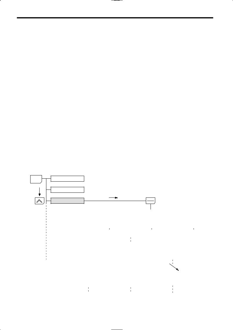
In general, press the DATA/ENTER Key to move from an upper to a lower level. This varies somewhat, however, according to the access level, as shown in Fig. 1.1. For the Quick-Start access level, which has few user constants that can be set, pressing the DATA/ENTER Key jumps directly to the user constant level; whereas for the Advanced access level, which has many user constants, pressing the DATA/ENTER Key first leads to the Group level.
|
MENU |
Operation mode |
|
Initialize mode |
|
|
Programming mode |
|
[Basic] |
||||||||||||||||||||||
|
[Advanced] |
[Quick-Start] |
|||||||||||||||||||||
|
Displays group level. |
Displays function level. |
Displays constant level. |
||||||||||||||||||||
|
Application |
b1 Sequence |
b1-01 |
Reference source |
|||||||||||||||||||
|
b1-02 |
Run source |
|||||||||||||||||||||
|
Constant to be changed |
b1-03 |
Stopping method |
||||||||||||||||||||
|
Tuning |
C1 Accel/Decel |
C1-01 Accel Time 1 |
||||||||||||||||||||
|
Reference |
C2 S-curve Acc/Dec |
C1-02 Decel Time 1 |
||||||||||||||||||||
|
[Mode] |
[Groups] |
[Functions] |
[Constants] |
|||||||||||||||||||
|
Fig 1.1 |
Access Level Structure |
1 — 6
1.2 Nomenclature
1.2 Nomenclature
This section provides the names of VS-616G5 components, and the components and functions of the Digital Operator.
1.2.1 VS-616G5 Components
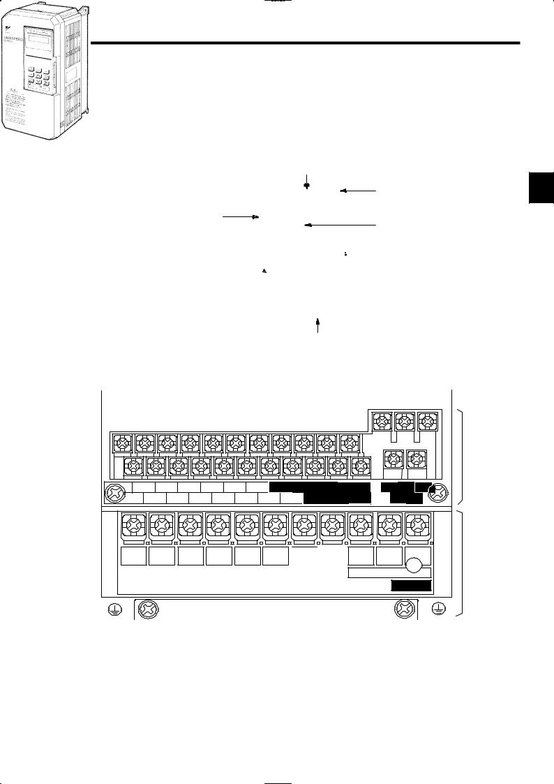
The appearance of Inverter and the names of its components are shown in Figure 1.2.
|
Protective cover (top) |
|
|
Mounting hole |
1 |
Front cover
Digital Operator
JVOP-130
 Die-cast case
|
Protective cover (bottom) |
||||||
|
Fig 1.2 |
Appearance of VS-616G5,Model |
CIMR-G5A20P4 |
(200 |
V, |
0.4 |
kW) |
|
A 200 V |
Class Inverter with 0.4 kW Output |
is shown below |
with |
the |
front |
cover removed. |
Control circuit terminals
|
11 12(G) |
13 |
14 |
15 |
16 |
17 |
25 |
26 |
27 |
33 |
||
|
1 |
2 |
3 |
4 |
5 |
6 |
7 |
8 |
21 |
22 |
23 |
|
R |
S |
T |
© |
¨1 |
¨2 |
B1 |
B2 |
|
|
L1 |
L2 |
L3 |
||||||
|
Power input |
Braking Resistor |
|
U |
V |
W/T3 |
|
|
T1 |
T2 |
Main circuit |
|
|
Motor output |
|||
|
terminals |
|||
|
CHARGE |
Fig 1.3 Terminal Arrangement
1 — 7
Introduction
1.2.2Digital Operator Components
1.2.2Digital Operator Components
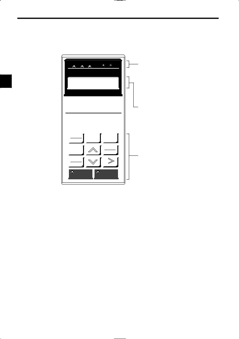
This section describes the component names and functions of the Digital Operator. The component names and functions are shown in Figure 1.4 and key functions are described in Table 1.4.
|
DRIVE FWD REV |
REMOTE |
||
|
SEQ |
REF |
||
|
1 |
Frequency Ref |
||
|
U1−01 = |
00.00 HZ |
DIGITAL OPERATOR
JVOP−130
Operation Mode Indicators
|
DRIVE: |
Lit when in operation mode. |
|
FWD: |
Lit when there is a forward reference input. |
|
REV: |
Lit when there is a reverse reference input. |
|
SEQ: |
Lit when an operation reference from the |
|
control circuit terminal is enabled. |
|
|
REF: |
Lit when the frequency reference from con- |
|
trol circuit terminals 13 and 14 is enabled. |
Data Display
LOCAL
MENU ESC
REMOTE
|
JOG |
DATA |
|
|
ENTER |
||
|
FWD |
||
|
REV |
RESET |
|
|
RUN |
STOP |
Two-line LCD that displays data for monitoring, user constants, and set values with 16 characters per line.
Keys
Execute operations such as setting user constants, monitoring, jogging, and autotuning.
Fig 1.4 Digital Operator Component Names and Functions
1 — 8
1.2 Nomenclature
|
Table 1.4 |
Key Functions |
||||||||||
|
Key |
Name |
Function |
|||||||||
|
Switches between (LOCAL) operation via the Digital Operator |
|||||||||||
|
LOCAL |
LOCAL/REMOTE Key |
and control circuit terminal (REMOTE) operation. |
|||||||||
|
REMOTE |
This key can be enabled or disabled by setting a user constant |
||||||||||
|
(o2-01). |
|||||||||||
|
MENU |
MENU Key |
Displays menus. |
|||||||||
|
Returns to the status before the DATA/ENTER Key was |
|||||||||||
|
ESC |
ESC Key |
1 |
|||||||||
|
pressed. |
|||||||||||
|
JOG |
JOG Key |
Enables jog operation when the VS-616G5 is being operated |
|||||||||
|
from the Digital Operator. |
|||||||||||
|
FWD |
FWD/REV Key |
Selects the rotation direction of the motor when the VS-616G5 |
|||||||||
|
REV |
is being operated from the Digital Operator. |
||||||||||
|
RESET Key |
Sets the number of digits for user constant settings. |
||||||||||
|
RESET |
Also acts as the reset key when a fault has occurred. |
||||||||||
|
Increment Key |
Selects menu items, groups, functions, and user constant |
||||||||||
|
names, and increments set values. |
|||||||||||
|
Decrement Key |
Selects menu items, groups, functions, and user constant |
||||||||||
|
names, and decrements set values. |
|||||||||||
|
DATA |
DATA/ENTER Key |
Enters menu items, functions, constants, and set values after |
|||||||||
|
ENTER |
they are set. |
||||||||||
|
RUN |
RUN Key |
Starts the VS-616G5 operation when the VS-616G5 is in opera- |
|||||||||
|
tion with the Digital Operator. |
|||||||||||
|
Stops VS-616G5 operation. |
|||||||||||
|
STOP |
STOP Key |
This key can be enabled or disabled by setting a user constant |
|||||||||
|
(o2-02) when operating from the control circuit terminal. |
|||||||||||
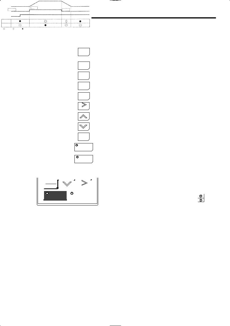
Note Except in diagrams, keys are referred to using the key names listed in the above table.
|
Inverter output frequency |
|||||||||||||||||||
|
RESET |
STOP |
RUN |
STOP |
||||||||||||||||
|
Frequency setting |
|||||||||||||||||||
|
STOP |
RUN |
||||||||||||||||||
|
STOP |
: |
: |
|||||||||||||||||
|
: |
|||||||||||||||||||
|
Lit |
Blinking |
Not lit |
The RUN and STOP indicators light and blink to indicate operating status.
During DB (initial excitation), RUN blinks and STOP is turned ON.
Fig 1.5 RUN and STOP Indicators
1 — 9

2
Handling Inverters |
2 |
This chapter describes the checks required upon receiving a VS-616G5 Inverter and describes installation methods.
|
2.1 |
Confirmations upon Delivery . . . . . . . . . . . . |
2 — 2 |
|
|
2.1.1 |
Nameplate Information . . . . . . . . . . . . . . . . . . . . . . . |
2 — 2 |
|
|
2.2 |
Exterior and Mounting Dimensions . . . . . . . |
2 — 4 |
|
|
2.3 |
Checking and Controlling the |
||
|
Installation Site . . . . . . . . . . . . . . . . . . . . . . . |
2 — 6 |
||
|
2.3.1 |
Installation Site . . . . . . . . . . . . . . . . . . . . . . . . . . . . . . |
2 — 6 |
|
|
2.3.2 |
Controlling the Ambient Temperature . . . . . . . . . . . |
2 — 6 |
|
|
2.3.3 |
Protecting the Inverter from Foreign Matter . . . . . . |
2 — 6 |
|
|
2.4 |
Installation Orientation and Space . . . . . . . |
2 — 7 |
|
|
2.5 |
Removing/Attaching the Digital Operator |
||
|
and Front Cover . . . . . . . . . . . . . . . . . . . . . . |
2 — 8 |
||
|
2.5.1 |
Inverters of 15 kW or Less . . . . . . . . . . . . . . . . . . . . |
2 — 8 |
|
|
2.5.2 |
Inverters of 18.5 kW or Higher . . . . . . . . . . . . . . . . . |
2 — 9 |
2 — 1
Handling Inverters
2.1.1Nameplate Information
2.1Confirmations upon Delivery
CAUTION
DNever install an Inverter that is damaged or missing components.
Doing so can result in injury.
Check the following items as soon as the Inverter is delivered.
|
Table 2.1 |
Checks |
|||
|
Item |
Method |
|||
|
Has the correct model of Inverter been |
Check the model number on the nameplate on the side of the Inverter (See |
|||
|
delivered? |
2.1.1). |
|||
|
2 |
||||
|
Is the Inverter damaged in any way? |
Inspect the entire exterior of the Inverter to see if there are any scratches or |
|||
|
other damage resulting from shipping. |
||||
|
Are any screws or other components |
Use a screwdriver or other tools to check for tightness. |
|||
|
loose? |
||||
If you find any irregularities in the above items, contact the agency from which you purchased the Inverter or your Yaskawa representative immediately.
2.1.1 Nameplate Information
J Example Nameplate
Standard domestic (Japan) Inverter: 3-phase, 200 VAC, 0.4 kW, IEC IP20 and NEMA 1 standards
|
Model number |
MODEL |
: CIMR-G5A20P4 |
SPEC: 20P41F |
Inverter specifications |
|
|
Input specifications |
INPUT |
: AC 3PH |
200-220 V |
50Hz |
|
|
Output specifications |
200-230 V |
60Hz |
|||
|
OUTPUT: AC 3PH |
0-230 |
V 1.2kVA 3.2 A |
|||
|
Lot number |
LOT NO : |
MASS : 3.0kg |
Mass |
||
|
Serial number |
SER NO : |
|
YASKAWA ELECTRIC CORPORATION |
JAPAN |
J Inverter Model Numbers
CIMR — G5 A 2 0P4
Inverter
VS-616G5
|
No. |
Specification |
||
|
A |
Standard domestic model |
||
|
V |
UL/C-UL model |
||
|
No. |
Voltage Class |
||
|
2 |
AC input, 3-phase, 200 V |
||
|
4 |
AC input, 3-phase, 400 V |
||
|
D |
DC input, 3-phase, 200 V |
||
|
E |
DC input, 3-phase, 400 V |
|
No. |
Max. Motor Capacity |
|
|
0P4 |
0.4 kW |
|
|
0P7 |
0.75 kW |
|
|
to |
to |
|
|
075 |
75 kW |
“P” indicates the decimal point.
2 — 2

2.1 Confirmations upon Delivery
J Inverter Specifications
|
No. |
Voltage Class |
|
|
2 |
AC input, 3-phase, 200 V |
|
|
4 |
AC input, 3-phase, 400 V |
|
|
D |
DC input, 3-phase, 200 V |
|
|
E |
DC input, 3-phase, 400 V |
|
|
No. |
Max. Motor Capacity |
|
|
0P4 |
0.4 kW |
|
|
0P7 |
0.75 kW |
|
|
to |
to |
|
|
075 |
75 kW |
“P” indicates the decimal point.
2 0P4 1 F
Version (Enter the specifications form number when special specifications are required.)
|
No. |
Protective Structure |
|
0 |
Open chassis (IEC IP00) |
|
1 |
Enclosed wall-mounted (IEC IP20, NEMA 1) |
2
DOpen Chassis Type (IEC IP00)
Protected so that parts of the human body cannot reach electrically charged parts from the front when the Inverter is mounted in a control panel.
DEnclosed Wall-mounted Type (IEC IP20, NEMA 1)
The Inverter is structured so that the Inverter is shielded from the exterior, and can thus be mounted to the interior wall of a standard building (not necessarily enclosed in a control panel). The protective structure conforms to the standards of NEMA 1 in the USA.
2 — 3
![]()
2
Handling Inverters
2.2 Exterior and Mounting Dimensions
J 200 V/400 V Class Inverters of 15 kW and Lower
The following diagram shows a 200 V class, 1.5 kW Inverter.
Remove the top and bottom covers when mounting 200 V/400 V class Inverters of 15 kW or lower in a control panel.
H1
H
|
W1 |
H2 |
D |
|
|
W |
|||
|
4-d |
J 200 V/400 V Class Inverters of 18.5 kW and Higher
The following diagram shows a 200 V class, 18.5 kW Inverter.
H 1
H
|
W1 |
H2 |
|
|
D |
||
|
W |
4-d |
|
J Mounting Dimensions for 400 V Class Inverters of 185 to 300 kW
|
W4 |
||||||||||||
|
Max. Applicable Motor |
||||||||||||
|
W5 W6 |
W1 |
W2 |
W3 |
W4 |
W5 |
W6 |
||||||
|
Capacity |
||||||||||||
|
[kW] |
||||||||||||
|
185, 220 |
750 |
440 |
310 |
850 |
285 |
565 |
||||||
|
300 |
750 |
440 |
310 |
873 |
298 |
575 |
||||||
W2 W3
W1
2 — 4

2.2 Exterior and Mounting Dimensions
|
Table |
2.2 |
VS-616G5 |
External |
Dimensions (mm) and Approx. Masses (kg) |
||||||||||||||||||
|
Max. Ap- |
Open Chassis (IP00) |
Enclosed Wall-mounted (NEMA1) |
||||||||||||||||||||
|
Volt- |
plicable |
DC |
||||||||||||||||||||
|
age |
Motor Out- |
W |
H |
D |
W1 |
H1 |
H2 |
Approx. |
W |
H |
D |
W1 |
H1 |
H2 |
Approx. |
Mounting |
Reac- |
|||||
|
class |
put |
Holes |
tor*1 |
|||||||||||||||||||
|
Mass |
Mass |
|||||||||||||||||||||
|
[kW] |
d *1 |
|||||||||||||||||||||
|
0.4 |
||||||||||||||||||||||
|
0.75 |
140 |
280 |
160 |
126 |
266 |
7.0 |
3 |
140 |
280 |
160 |
126 |
266 |
7.0 |
3 |
M5 |
|||||||
|
1.5 |
||||||||||||||||||||||
|
2.2 |
140 |
280 |
180 |
126 |
266 |
7.0 |
4.5 |
140 |
280 |
180 |
126 |
266 |
7.0 |
4.5 |
M5 |
|||||||
|
Op- |
||||||||||||||||||||||
|
3.7 |
||||||||||||||||||||||
|
tion |
||||||||||||||||||||||
|
5.5 |
200 |
300 |
205 |
186 |
285 |
8.0 |
5.5 |
200 |
300 |
205 |
186 |
285 |
8.0 |
5.5 |
M6 |
|||||||
|
7.5 |
6 |
6 |
2 |
|||||||||||||||||||
|
200 V |
11 |
250 |
380 |
225 |
236 |
365 |
7.5 |
11 |
250 |
380 |
225 |
236 |
365 |
7.5 |
11 |
M6 |
||||||
|
class |
15 |
400 |
27.5 |
|||||||||||||||||||
|
18.5 |
325 |
450 |
285 |
275 |
435 |
7.5 |
28 |
330 |
610 |
285 |
275 |
435 |
87.5 |
32 |
M6 |
|||||||
|
22 |
675 |
152.5 |
||||||||||||||||||||
|
30 |
425 |
675 |
350 |
320 |
650 |
12.5 |
61 |
430 |
985 |
350 |
320 |
650 |
212.5 |
67 |
M10 |
|||||||
|
Built- |
||||||||||||||||||||||
|
37 |
62 |
68 |
||||||||||||||||||||
|
in |
||||||||||||||||||||||
|
45 |
475 |
800 |
350 |
370 |
775 |
12.5 |
80 |
480 |
1110 |
350 |
370 |
775 |
212.5 |
87 |
M10 |
|||||||
|
55 |
||||||||||||||||||||||
|
75 |
575 |
925 |
400 |
445 |
895 |
15.0 |
135 |
580 |
1290 |
400 |
445 |
895 |
270 |
145 |
M12 |
|||||||
|
0.4 |
140 |
280 |
160 |
126 |
266 |
7.0 |
3 |
140 |
280 |
160 |
126 |
266 |
7.0 |
3 |
M5 |
|||||||
|
0.75 |
||||||||||||||||||||||
|
1.5 |
4 |
4 |
||||||||||||||||||||
|
2.2 |
140 |
280 |
180 |
126 |
266 |
7.0 |
4.5 |
140 |
280 |
180 |
126 |
266 |
7.0 |
4.5 |
M5 |
|||||||
|
Op- |
||||||||||||||||||||||
|
3.7 |
||||||||||||||||||||||
|
tion |
||||||||||||||||||||||
|
5.5 |
200 |
300 |
205 |
186 |
285 |
8.0 |
6 |
200 |
300 |
205 |
186 |
285 |
8.0 |
6 |
M6 |
|||||||
|
7.5 |
||||||||||||||||||||||
|
11 |
250 |
380 |
225 |
236 |
365 |
7.5 |
11 |
250 |
380 |
225 |
236 |
365 |
7.5 |
11 |
M6 |
|||||||
|
15 |
||||||||||||||||||||||
|
18.5 |
325 |
450 |
285 |
275 |
435 |
7.5 |
29 |
330 |
610 |
285 |
275 |
435 |
87.5 |
32 |
M6 |
|||||||
|
400 V |
||||||||||||||||||||||
|
22 |
31 |
34 |
||||||||||||||||||||
|
class |
||||||||||||||||||||||
|
30 |
785 |
87.5 |
||||||||||||||||||||
|
37 |
325 |
625 |
285 |
275 |
610 |
7.5 |
44 |
330 |
285 |
275 |
610 |
48 |
M6 |
|||||||||
|
Built- |
||||||||||||||||||||||
|
45 |
850 |
152.5 |
||||||||||||||||||||
|
in |
||||||||||||||||||||||
|
55 |
455 |
820 |
350 |
350 |
795 |
12.5 |
81 |
460 |
1130 |
350 |
350 |
795 |
212.5 |
87 |
M10 |
|||||||
|
75 |
82 |
88 |
||||||||||||||||||||
|
110 |
575 |
925 |
375 |
445 |
895 |
15.0 |
135 |
580 |
1290 |
375 |
445 |
895 |
270 |
145 |
M12 |
|||||||
|
160 |
400 |
145 |
400 |
155 |
||||||||||||||||||
|
185 |
950 |
1450 |
435 |
*2 |
1400 |
25 |
360 |
|||||||||||||||
|
220 |
M12 |
|||||||||||||||||||||
|
300 |
960 |
1600 |
455 |
*2 |
1550 |
25 |
420 |
* 1. Same for open chassis and enclosed wall-mounted types.
|
* 2. |
See page 2 — 4 for mounting dimensions. |
|
Note |
An attachment is required to mount the cooling fins (fin section) on the outside of the control panel for 200 V/400 V class |
|
Inverters of 15 kW or less. Please contact your Yaskawa representative for details. Dimensional drawings for models with |
|
|
externally mounted cooling fins and other special requirements are also available from your Yaskawa representative. |
2 — 5

Handling Inverters
2.3.1Installation Site
2.3Checking and Controlling the Installation Site
CAUTION
DAlways hold the case when carrying the Inverter.
If the Inverter is held by the front cover, the main body of the Inverter may fall, possibly resulting in injury.
DAttach the Inverter to a metal or other noncombustible material.
Fire can result if the Inverter is attached to a combustible material.
DInstall a cooling fan or other cooling device when installing more than one Inverter in the same enclosure so that the temperature of the air entering the Inverters is below 45_C.
Overheating can result in fires or other accidents.
|
Install the VS-616G5 in the installation site described below and maintain optimum conditions. |
|||||
|
2 |
|||||
2.3.1 Installation Site |
|||||
|
Install the Inverter under the following conditions. |
|||||
|
Type |
Ambient Operating Temperature |
Humidity |
|||
|
Enclosed wall- |
−10 to 40_C |
90% RH or less (no condensation) |
|||
|
mounted |
|||||
|
Open chassis |
−10 to 45_C |
90% RH or less (no condensation) |
|||
Protection covers are attached to the top and bottom of the Inverter. Be sure to remove the protection covers before installing a 200 or 400 V Class Inverter with an output of 15 kW or less in a panel.
DInstall the Inverter in a clean location free from oil mist and dust. It can be installed in a totally enclosed panel that is completely shielded from floating dust.
DWhen installing or operating the Inverter, always take special care so that metal powder, oil, water, or other foreign matter does not get into the Inverter.
D Do not install the Inverter on combustible material, such as wood.
D Install the Inverter in a location free from radioactive materials and combustible materials.
D Install the Inverter in a location free from harmful gasses and liquids.
D Install the Inverter in a location without excessive oscillation.
D Install the Inverter in a location free from chlorides.
DInstall the Inverter in a location not in direct sunlight.
2.3.2Controlling the Ambient Temperature
To enhance the reliability of operation, the Inverter should be installed in an environment free from extreme temperature increases. If the Inverter is installed in an enclosed environment, such as a box, use a cooling fan or air conditioner to maintain the internal air temperature below 45°C.
2.3.3 Protecting the Inverter from Foreign Matter
Place a cover over the Inverter during installation to shield it from metal power produced by drilling.
Always remove the cover from the Inverter after completing installation. Otherwise, ventilation will be reduced, causing the Inverter to overheat.
2 — 6

2.4 Installation Orientation and Space
2.4 Installation Orientation and Space
Install the Inverter on a vertical surface so as not to reduce the cooling effect. When installing the Inverter, always provide the following installation space to allow normal heat dissipation.
 50 mm min.
30 mm min. 30 mm min.
 50 mm min.
(a) Horizontal Space
Air
120 mm min.
2
120 mm min.
Air
(b) Vertical Space
Fig 2.1 VS-616G5 Installation Orientation and Space
IMPORTANT S The same space is required horizontally and vertically for both open chassis (IP00) and enclosed wall-mounted (IP20, NEMA 1) Inverters.
S Always remove the protection covers before installing a 200 or 400 V Class Inverter with an output of 15 kW or less in a panel.
S Always provide enough space for suspension eye bolts and the main circuit lines when installing a 200 or 400 V Class Inverter with an output of 30 kW or more in a panel.
2 — 7

Handling Inverters
2.5.1Inverters of 15 kW or Less
2.5Removing/Attaching the Digital Operator and Front Cover
Remove the front cover to wire the terminals.
For models of 15 kW or less (both 200 V and 400 V class), do not remove or mount the front cover without first removing the Digital Operator; otherwise, the Digital Operator may malfunction due to imperfect contact. Use the following procedures to remove or attach the front cover.
2.5.1 Inverters of 15 kW or Less
J Removing the Digital Operator
Press the lever on the side of the Digital Operator in the direction of arrow 1 to unlock the Digital Operator and lift the Digital Operator in the direction of arrow 2 to remove the Digital Operator as shown in the following illustration.
|
2 |
2 |
|
|
Front cover |
||
|
Digital |
||
|
Operator |
1 |
Fig 2.2 Removing the Digital Operator
J Removing the Front Cover
Press the left and right sides of the front cover in the directions of arrows 1 and lift the bottom of the cover in the direction of arrow 2 to remove the front cover as shown in the following illustration.
Front cover 
1
 2
2
1
Fig 2.3 Removing the Front Cover
J Mounting the Front Cover
After wiring the terminals, mount the front cover to the Inverter by performing in reverse order to the steps to remove the front cover.
1.Do not mount the front cover with the Digital Operator attached to the front cover; otherwise, Digital Operator may malfunction due to imperfect contact.
2.Insert the tab of the upper part of the front cover into the groove of the Inverter and press the lower part of the front cover onto the Inverter until the front cover snaps shut.
2 — 8

2.5 Removing/Attaching the Digital Operator and Front Cover
JMounting the Digital Operator
1.Hook the Digital Operator at A (two locations) on the front cover in the direction of arrow 1 as shown in the following illustration.
2.Press the Digital Operator in the direction of arrow 2 until it snaps in place at B (two locations).
Digital
Operator
2
1
2
B
Fig 2.4 Mounting the Digital Operator
IMPORTANT 1. Do not remove or attach the Digital Operator or mount or remove the front cover using methods other than those described above, otherwise the Inverter may break or malfunction due to imperfect contact.
2.Never attach the front cover to the Inverter with the Digital Operator attached to the front cover. Imperfect contact can result.
Always attach the front cover to the Inverter by itself first, and then attach the Digital Operator to the front cover.
2.5.2 Inverters of 18.5 kW or Higher
The front cover can be removed without removing the Digital Operator from the Inverter provided that the Inverter has an output of 18.5 kW or higher.
Loosen the four screws of the front cover and move the front cover slightly upwards to remove the front cover.
2 — 9

3
Wiring
3
This chapter describes wiring terminals, main circuit terminal connections, main circuit terminal wiring specifications, control circuit terminals, and control circuit wiring specifications.
|
3.1 |
Connections to Peripheral Devices . . . . . . |
3 — 3 |
|
|
3.2 |
Connection Diagram . . . . . . . . . . . . . . . . . . . |
3 — 4 |
|
|
3.3 |
Terminal Block Configuration . . . . . . . . . . . . |
3 — 5 |
|
|
3.4 |
Wiring Main Circuit Terminals . . . . . . . . . . . |
3 — 6 |
|
|
3.4.1 |
Applicable Wire Sizes and Closed-loop |
||
|
Connectors . . . . . . . . . . . . . . . . . . . . . . . . . . . . . . . |
3 — 6 |
||
|
3.4.2 |
Main Circuit Terminal Functions . . . . . . . . . . . . . . . |
3 — 9 |
|
|
3.4.3 |
Main Circuit Configurations . . . . . . . . . . . . . . . . . . . |
3 — 10 |
|
|
3.4.4 |
Standard Connection Diagrams . . . . . . . . . . . . . . . |
3 — 12 |
|
|
3.4.5 |
Wiring the Main Circuits . . . . . . . . . . . . . . . . . . . . . . |
3 — 13 |
|
|
3.5 |
Wiring Control Circuit Terminals . . . . . . . . . |
3 — 20 |
|
|
3.5.1 |
Wire Sizes and Closed-loop Connectors . . . . . . . . |
3 — 20 |
|
|
3.5.2 |
Control Circuit Terminal Functions . . . . . . . . . . . . . |
3 — 21 |
|
|
3.5.3 |
Control Circuit Terminal Connections (All Models) |
3 — 22 |
|
|
3.5.4 |
Control Circuit Wiring Precautions . . . . . . . . . . . . . |
3 — 23 |
|
|
3.6 |
Wiring Check . . . . . . . . . . . . . . . . . . . . . . . . . |
3 — 23 |
|
|
3.7 |
Installing and Wiring PG Speed Control |
||
|
Cards . . . . . . . . . . . . . . . . . . . . . . . . . . . . . . . |
3 — 24 |
||
|
3.7.1 |
Installing a PG Speed Control Card . . . . . . . . . . . . |
3 — 24 |
|
|
3.7.2 |
PG Speed Control Card Terminal Blocks . . . . . . . . |
3 — 25 |
|
|
3.7.3 |
Wiring a PG Speed Control Card . . . . . . . . . . . . . . |
3 — 27 |
|
|
3.7.4 |
Wiring PG Speed Control Card Terminal Blocks . |
3 — 31 |
|
|
3.7.5 |
Selecting the Number of PG (Encoder) Pulses . . . |
3 — 33 |
3 — 1

 WARNING
DAlways turn OFF the input power supply before wiring terminals.
Otherwise, an electric shock or fire can occur.
DWiring must be performed by an authorized person qualified in electrical work.
Otherwise, an electric shock or fire can occur.
DBe sure to ground the ground terminal.
(200 V class: Ground to 100 Ω or less, 400 V class: Ground to 10 Ω or less) Otherwise, an electric shock or fire can occur.
DAlways check the operation of any emergency stop circuits after they are wired.
Otherwise, there is the possibility of injury. (Wiring is the responsibility of the user.)
DNever touch the output terminals directly with your hands or allow the output lines to come into contact with the Inverter case. Never short the output circuits.
Otherwise, electrical shock or grounding can occur.
CAUTION
DCheck to be sure that the voltage of the main AC power supply satisfies the rated voltage of the Inverter.
Injury or fire can occur if the voltage is not correct.
DDo not perform voltage withstand tests on the Inverter.
Otherwise, semiconductor elements and other devices can be damaged.
DConnect braking resistors, Braking Resistor Units, and Braking Units as shown in the I/O wiring examples.
Otherwise, a fire can occur.
DTighten all terminal screws to the specified tightening torque.
Otherwise, a fire may occur.
DDo not connect AC power to output terminals U, V, and W.
The interior parts of the Inverter will be damaged if voltage is applied to the output terminals.
DDo not connect phase-advancing capacitors or LC/RC noise filters to the output circuits.
The Inverter can be damaged or internal parts burnt if these devices are connected.
DDo not connect electromagnetic switches or contactors to the output circuits.
If a load is connected while the Inverter is operating, surge current will cause the overcurrent protection circuit inside the Inverter to operate.
3 — 2

3.1 Connections to Peripheral Devices
3.1 Connections to Peripheral Devices
Examples of connections between the VS-616G5 and typical peripheral devices areFigureshown3.1. Usein this illustration to gain an understanding of the overall equipment configuration.
Power supply
Molded-case circuit breaker or ground fault interrupter
Magnetic contactor
AC reactor for power factor improvement
Input noise filter
VS-616G5
Ground
Ground
3
DC reactor for power factor improvement
Output noise filter
Motor
Fig 3.1 Example Connections to Peripheral Devices
3 — 3

Wiring
3.2 Connection Diagram
|
The connection diagram of the VS-616G5 |
is |
shownFigure in3.2. |
||||||||||||
|
When using the Digital Operator, the motor can be operated by wiring only the main circuits. |
||||||||||||||
|
DC reactor to improve input |
Braking Resistor Unit (Optional) |
|||||||||||||
|
power factor (optional) |
||||||||||||||
|
Short-circuit bar |
||||||||||||||
|
MCCB |
© ¨ 1 ¨ 2 B1 |
B2 |
||||||||||||
|
3-phase power |
R |
R (L1) |
U (T1) |
Motor |
||||||||||
|
S |
S (L2) |
|||||||||||||
|
200 to 230 V |
V (T2) |
IM |
||||||||||||
|
50/60 Hz |
T |
T (L3) |
W (T3) |
|||||||||||
|
VS-616G5 |
||||||||||||||
|
Forward Run/Stop |
Forward run command |
|||||||||||||
|
Reverse Run/Stop |
(Ground to 100 Ω max.) |
|||||||||||||
|
(forward when closed) |
||||||||||||||
|
Reverse run command |
||||||||||||||
|
3 |
||||||||||||||
|
External fault |
(reverse when closed) |
23 |
||||||||||||
|
3 |
||||||||||||||
|
Analog |
||||||||||||||
|
Fault reset |
+ |
|||||||||||||
|
4 |
monitor 2 |
Multi-function analog output |
||||||||||||
|
Multi-step speed setting 1 |
AM |
−10 to 10 V |
||||||||||||
|
Factory- |
(Master/auxiliary switch) |
5 |
Multi-function |
contact |
(Default: Output current |
|||||||||
|
− 5 V/Inverter rated current) |
||||||||||||||
|
preset |
Multi-step speed setting 2 |
|||||||||||||
|
inputs |
||||||||||||||
|
functions |
||||||||||||||
|
6 |
||||||||||||||
|
Jog frequency reference |
||||||||||||||
|
21 |
||||||||||||||
|
7 |
Multi-function analog output |
|||||||||||||
|
Analog |
||||||||||||||
|
External baseblock command |
−10 to10 V |
|||||||||||||
|
monitor 1 |
22 |
|||||||||||||
|
8 |
− FM + (Default: Output frequency |
|||||||||||||
|
0 to 10 V/100% frequency) |
||||||||||||||
|
11 |
Sequence common |
(12) |
||||||||||||
|
(Insulated from 0 V |
||||||||||||||
|
terminal) |
||||||||||||||
|
2 kΩ |
12 Shield wire connection terminal |
18 |
||||||||||||
|
15 Frequency setting power |
||||
|
0 to 10 V |
15 V, 20 mA |
|||
|
13 Master speed reference |
||||
|
2 kΩ |
||||
|
External |
−10 to 10 V (20 kΩ) |
|||
|
frequency |
4 to 20 mA P |
(Default: 0 to 10 V/100%) |
||
|
references |
14 Master speed reference |
|||
|
P |
4 to 20 mA (250 Ω) |
|||
|
0 to 10 V |
||||
|
16 Multi-function analog input |
||||
|
0 V |
P |
(−10 to 10 V (20 kΩ) |
||
|
17 (Default: Auxiliary frequency |
||||
reference
0 to 10 V/100%)
0 V
19Fault contact output 250 VAC, 1 A max.
30 VDC, 1 A max.
20
9 Multi-function contact output
250 VAC, 1 A max.
1030 VDC, 1 A max. (Default: Running signal)
|
33 |
25 |
Open collector 1 |
||
|
Frequency setting |
||||
|
(Default: Zero speed |
||||
|
power: |
||||
|
signal) |
||||
|
−15 V, 20 mA |
||||
|
26 |
Open collector 2 |
Multi-function |
||
|
(Default: Speed agree |
open-collector |
|||
|
signal) |
output |
|||
|
27 |
48 V , 50 mA |
|
Multi-function output |
max. |
|
common |
* Shield
Fig 3.2 Connection Diagram (Model CIMR-G5A27P5 Shown Above)
3 — 4
![]()
3.3 Terminal Block Configuration
|
IMPORTANT |
1. |
Control circuit terminals 1 to 33 are not arranged in order of terminal numbers; they are arranged as shown |
|||||||||||||||||||||||||||||
|
below. Be sure to wire them correctly. |
|||||||||||||||||||||||||||||||
|
11 |
12(G) |
13 |
14 |
15 |
16 |
17 |
25 |
26 |
27 |
33 |
18 |
19 |
20 |
||||||||||||||||||
|
1 |
2 |
3 |
4 |
5 |
6 |
7 |
8 |
21 |
22 |
23 |
9 |
10 |
|||||||||||||||||||
|
2. |
Do not use control circuit terminals 13 and 14 at the same time. |
||||||||||||||||||||||||||||||
|
(The two signals will be added inside the Inverter if they are input at the same time.) |
3.The maximum output current capacity of the +15 V/−15 V output from control circuit terminals 15 and 33 is 20 mA.
4.The multi-function analog output is a dedicated meter output for a frequency meter, ammeter, etc. Do not use this output for feedback control or for any other control purpose.
Use one of the optional Analog Monitor Cards (AO-08 or AO-012) for analog outputs to the control system.
5.Disable the stall prevention during deceleration (set constant L3-04 to 0) when using a Braking Resistor Unit. If this user constant is not changed to disable stall prevention, the system may not stop during deceleration.
|
6. Enable protection for the internal DB resistor (model ERF) (set constant L8-01 to 1) when using an inter- |
3 |
|
nal braking resistor. The braking resistor will not be protected unless this setting is changed to enable |
|
|
protection. |
|
7.DC reactors to improve the input power factor can be connected as an option only to Inverters for 15 kW or less. Remove the short bar from between ¨1 and ¨2 when connecting a DC reactor.
8.There is no DC power supply input terminals for 200 V class Inverters of 30 to 75 kW and 400 V class Inverters of 55 to 160 kW, and DC power cannot be input to these Inverters.
3.3Terminal Block Configuration
The terminal block for a 200 V classwithInverteran output of 0.4 kW is shownFigure in3.3.
Control circuit terminals
|
11 12(G) |
13 |
14 |
15 |
16 |
17 |
25 |
26 |
27 |
33 |
||
|
1 |
2 |
3 |
4 |
5 |
6 |
7 |
8 |
21 |
22 |
23 |
|
R |
S |
T |
© |
¨1 |
¨2 |
B1 |
B2 |
U |
V |
W/T3 |
|
L1 |
L2 |
L3 |
T1 |
T2 |
||||||
|
Main circuit |
||||||||||
|
Power input |
Braking resistor |
Motor output |
||||||||
|
terminals |
||||||||||
|
CHARGE |
Fig 3.3 Terminal Arrangement
3 — 5

Wiring
3.4.1Applicable Wire Sizes and Closed-loop Connectors
3.4Wiring Main Circuit Terminals
3.4.1 Applicable Wire Sizes and Closed-loop Connectors
Select the appropriate wires and crimp terminalsTablefrom3 .1 to Table 3 . 3 . Refer to instruction manual
TOE-C726-2j for wire sizes for Braking Resistor Units and Braking Units.
|
Table 3.1 |
200 V Class |
Wire |
Sizes |
||||
|
Circuit |
VS-616G5 Model |
Terminal Symbol |
Termi- |
Wire Thickness |
Wire Type |
||
|
CIMR- |
nal |
(see note) |
|||||
|
Screws |
mm2 |
||||||
|
G5A20P4 |
R, S, T, © , ¨ 1 , ¨ 2, B1, B2, U, V, W |
M4 |
2 to 5.5 |
||||
|
G5A20P7 |
R, S, T, © , ¨ 1 , ¨ 2, B1, B2, U, V, W |
M4 |
2 to 5.5 |
||||
|
G5A21P5 |
R, S, T, © , ¨ 1 , ¨ 2, B1, B2, U, V, W |
M4 |
2 to 5.5 |
||||
|
3.5 to 5.5 |
|||||||
|
G5A22P2 |
R, S, T, © , ¨ 1 , ¨ 2, B1, B2, U, V, W |
M4 |
3.5 to 5.5 |
||||
|
3 |
G5A23P7 |
R, S, T, © , ¨ 1 , ¨ 2, B1, B2, U, V, W |
M4 |
5.5 |
|||
|
G5A25P5 |
R, S, T, © , ¨ 1 , ¨ 2, B1, B2, U, V, W |
M5 |
8 |
||||
|
5.5 to 8 |
|||||||
|
G5A27P5 |
R, S, T, © , ¨ 1 , ¨ 2, B1, B2, U, V, W |
M5 |
8 |
||||
|
5.5 to 8 |
|||||||
|
G5A2011 |
R, S, T, © , ¨ 1 , ¨ 2, ¨ 3, U, V, W |
M6 |
22 |
||||
|
8 |
|||||||
|
G5A2015 |
R, S, T, © , ¨ 1 , ¨ 2, ¨ 3, U, V, W |
M8 |
30 |
||||
|
M6 |
8 |
||||||
|
R, S, T, © , ¨ 1 , ¨ 2, ¨ 3, U, V, W |
M8 |
30 |
|||||
|
G5A2018 |
14 |
||||||
|
r , |
M4 |
0.5 to 5.5 |
|||||
|
Main |
R, S, T, © , ¨ 1 , ¨ 2, ¨ 3, U, V, W |
M8 |
38 |
Power cables, e.g., 600 V vinyl pow- |
|||
|
G5A2022 |
14 |
||||||
|
Circuits |
er cables |
||||||
|
r , |
M4 |
0.5 to 5.5 |
|||||
|
R, S, T, U, V, W |
M10 |
38 to 100 |
|||||
|
G5A2030 |
© , ¨ 3 |
M8 |
|||||
|
M8 |
22 |
||||||
|
r , |
M4 |
0.5 to 5.5 |
|||||
|
R, S, T, U, V, W |
M10 |
38 to 100 |
|||||
|
G5A2037 |
© , ¨ 3 |
M8 |
|||||
|
M8 |
22 |
||||||
|
r , |
M4 |
0.5 to 5.5 |
|||||
|
R, S, T, U, V, W |
M10 |
60 to 100 |
|||||
|
G5A2045 |
© , ¨ 3 |
M8 |
|||||
|
M8 |
22 |
||||||
|
r , |
M4 |
0.5 to 5.5 |
|||||
|
R, S, T, U, V, W |
M10 |
100 |
|||||
|
G5A2055 |
© , ¨ 3 |
M8 |
|||||
|
M8 |
30 |
||||||
|
r , |
M4 |
0.5 to 5.5 |
|||||
|
R, S, T, U, V, W |
M12 |
100 to 200 |
|||||
|
G5A2075 |
© , ¨ 3 |
M8 |
|||||
|
M8 |
50 |
||||||
|
r , |
M4 |
0.5 to 5.5 |
|||||
|
Control |
All models |
1 to 33 |
M3.5 |
0.5 to 2 |
Shielded twisted-pair wires |
||
|
Circuits |
|||||||
|
Note The wire thickness is set for copper wires at 75°C. |
3 — 6

3.4 Wiring Main Circuit Terminals
|
Table |
3.2 |
400 |
V Class |
Wire |
Sizes |
||||
|
Circuit |
VS-616G5 Model |
Terminal Symbol |
Termi- |
Wire Thickness |
Wire Type |
||||
|
nal |
(see note) |
||||||||
|
CIMR- |
|||||||||
|
Screws |
mm2 |
||||||||
|
G5A40P4 |
R, S, T, © , ¨ 1 , ¨ 2, B1, B2, U, V, W |
M4 |
2 to 5.5 |
||||||
|
G5A40P7 |
R, S, T, © , ¨ 1 , ¨ 2, B1, B2, U, V,W |
M4 |
2 to 5.5 |
||||||
|
G5A41P5 |
R, S, T, © , ¨ 1 , ¨ 2, B1, B2, U, V,W |
M4 |
2 to 5.5 |
||||||
|
G5A42P2 |
R, S, T, © , ¨ 1 , ¨ 2, B1, B2, U, V,W |
M4 |
2 to 5.5 |
||||||
|
G5A43P7 |
R, S, T, © , ¨ 1 , ¨ 2, B1, B2, U, V,W |
M4 |
2 to 5.5 |
||||||
|
3.5 to 5.5 |
|||||||||
|
G5A45P5 |
R, S, T, © , ¨ 1 , ¨ 2, B1, B2, U, V,W |
M4 |
3.5 to 5.5 |
||||||
|
G5A47P5 |
R, S, T, © , ¨ 1 , ¨ 2, B1, B2, U, V, W |
M5 |
5.5 |
||||||
|
G5A4011 |
R, S, T, © , ¨ 1 , ¨ 2, B1, B2, U, V, W |
M5 |
8 to 14 |
||||||
|
M6 |
8 |
3 |
|||||||
|
G5A4015 |
R, S, T, © , ¨ 1 , ¨ 2, B1, B2, U, V, W |
M5 |
8 to 14 |
||||||
|
M6 |
8 |
||||||||
|
R, S, T, © , ¨ 1 , ¨ 2, ¨ 3, U, V, W |
M6 |
14 |
|||||||
|
G5A4018 |
M8 |
8 |
|||||||
|
r , |
M4 |
0.5 to 5.5 |
|||||||
|
R, S, T, © , ¨ 1 , ¨ 2, ¨ 3, U, V, W |
M6 |
22 |
|||||||
|
G5A4022 |
M8 |
8 |
|||||||
|
r , |
M4 |
0.5 to 5.5 |
|||||||
|
R, S, T, © , ¨ 1 , ¨ 2, ¨ 3, U, V, W |
M8 |
22 |
|||||||
|
G5A4030 |
8 |
||||||||
|
r , |
M4 |
0.5 to 5.5 |
|||||||
|
R, S, T, © , ¨ 1 , ¨ 2, ¨ 3, U, V, W |
M8 |
30 |
|||||||
|
G5A4037 |
14 |
||||||||
|
Main |
Power cables, e.g., 600 V vinyl pow- |
||||||||
|
r , |
M4 |
0.5 to 5.5 |
|||||||
|
Circuits |
R, S, T, © , ¨ 1 , ¨ 2, ¨ 3, U, V, W |
50 |
er cables |
||||||
|
M8 |
|||||||||
|
G5A4045 |
14 |
||||||||
|
r , |
M4 |
0.5 to 5.5 |
|||||||
|
R, S, T, U, V, W |
M10 |
38 to 100 |
|||||||
|
G5A4055 |
© , ¨ 3 |
M8 |
|||||||
|
M8 |
22 |
||||||||
|
r , 200, |
400 |
M4 |
0.5 to 5.5 |
||||||
|
R, S, T, U, V, W |
M10 |
38 to 100 |
|||||||
|
G5A4075 |
© , ¨ 3 |
M8 |
|||||||
|
M8 |
22 |
||||||||
|
r , 200, |
400 |
M4 |
0.5 to 5.5 |
||||||
|
R, S, T, U, V, W |
M10 |
60 to 100 |
|||||||
|
G5A4110 |
© , ¨ 3 |
M8 |
|||||||
|
M8 |
30 |
||||||||
|
r , 200, |
400 |
M4 |
0.5 to 5.5 |
||||||
|
R, S, T, U, V, W |
M12 |
100 to 200 |
|||||||
|
G5A4160 |
© , ¨ 3 |
M8 |
|||||||
|
M8 |
50 |
||||||||
|
r , 200, |
400 |
M4 |
0.5 to 5.5 |
||||||
|
R, S, T, © , ¨ 1 , ¨ 3, U, V, W |
M16 |
250 to 325 |
|||||||
|
G5A4185 |
M8 |
50 |
|||||||
|
r , 200, |
400 |
M4 |
0.5 to 5.5 |
||||||
|
R, S, T, © , ¨ 1 , ¨ 3, U, V, W |
M16 |
325 or 200×2P |
|||||||
|
G5A4220 |
M8 |
60 |
|||||||
|
r , 200, |
400 |
M4 |
0.5 to 5.5 |
||||||
|
R, S, T, © , ¨ 1 , ¨ 3, U, V, W |
M16 |
250 × 2P or 325 |
|||||||
|
× 2P |
|||||||||
|
G5A4300 |
|||||||||
|
M8 |
60 |
||||||||
|
r , 200, |
400 |
M4 |
0.5 to 5.5 |
||||||
|
Control |
All models |
1 to 33 |
M3.5 |
0.5 to 2 |
Shielded twisted-pair wires |
||||
|
Circuits |
|||||||||
Note The wire thickness is set for copper wires at 75°C.
3 — 7

Wiring
3.4.1 Applicable Wire Sizes and Closed-loop Connectors
|
Table 3.3 |
Closed-loop Connector Sizes (JIS |
C 2805) (For 200 V/400 V Classes) |
|||||||||
|
Wire Thickness mm2 |
Terminal Screws |
Size |
|||||||||
|
0.5 |
M3.5 |
1.25 to 3.5 |
|||||||||
|
M4 |
1.25 to 4 |
||||||||||
|
0.75 |
M3.5 |
1.25 to 3.5 |
|||||||||
|
M4 |
1.25 to 4 |
||||||||||
|
1.25 |
M3.5 |
1.25 to 3.5 |
|||||||||
|
M4 |
1.25 to 4 |
||||||||||
|
M3.5 |
2 to 3.5 |
||||||||||
|
M4 |
2 to 4 |
||||||||||
|
2 |
M5 |
2 to 5 |
|||||||||
|
M6 |
2 to 6 |
||||||||||
|
M8 |
2 to 8 |
||||||||||
|
M4 |
5.5 to 4 |
||||||||||
|
3 |
|||||||||||
|
3.5/5.5 |
M5 |
5.5 to 5 |
|||||||||
|
M6 |
5.5 to 6 |
||||||||||
|
M8 |
5.5 to 8 |
||||||||||
|
M5 |
8 to 5 |
||||||||||
|
8 |
M6 |
8 to 6 |
|||||||||
|
M8 |
8 to 8 |
||||||||||
|
14 |
M6 |
14 to 6 |
|||||||||
|
M8 |
14 to 8 |
||||||||||
|
22 |
M6 |
22 to 6 |
|||||||||
|
M8 |
22 to 8 |
||||||||||
|
30/38 |
M8 |
38 to 8 |
|||||||||
|
50/60 |
M8 |
60 to 8 |
|||||||||
|
M10 |
60 to 10 |
||||||||||
|
80 |
M10 |
80 to 10 |
|||||||||
|
100 |
100 to 10 |
||||||||||
|
100 |
100 to 12 |
||||||||||
|
150 |
M12 |
150 to 12 |
|||||||||
|
200 |
200 to 12 |
||||||||||
|
325 |
M12 × 2 |
325 to 12 |
|||||||||
|
M16 |
325 to 16 |
||||||||||
|
IMPORTANT |
Determine the wire size for the main circuit so that line voltage drop is within 2% of the rated voltage. |
||||||||||
|
Line voltage drop is calculated as follows: |
(If there is the possibility of excessive voltage drop, use a larger wire suitable to the required length.) Line voltage drop (V) = 3 x wire resistance (Ω/km) x wire length (m) x current (A) x 10−3
3 — 8

3.4 Wiring Main Circuit Terminals
3.4.2 Main Circuit Terminal Functions
|
Main circuit |
terminal functions |
are summarized according to terminal symbolsTable 3.4inand Table |
||||||
|
3.5. Wire the terminals correctly for the desired |
purposes. |
|||||||
|
Table 3.4 |
200 V Class Main Circuit Terminal Functions |
|||||||
|
Purpose |
Terminal Symbol |
Model: CIMR-G5A |
||||||
|
Main circuit power input |
R (L1), S (L2), T (L3) |
20P4 to 2075 |
||||||
|
Inverter outputs |
U (T1), V (T2), W (T3) |
20P4 to 2075, D030 to D075 (all models) |
||||||
|
DC power input |
¨ 1 −© |
20P4 to 2022, D030 to D075 |
||||||
|
Braking Resistor Unit connec- |
B1, B2 |
20P4 to 27P5 |
||||||
|
tion |
||||||||
|
DC reactor connection |
¨ 1 −¨ 2 |
20P4 to 2015 |
||||||
|
Braking Unit connection |
¨ 3 −© (see note 2) |
2011 to 2075, D030 to D075 |
||||||
|
Cooling fan power input |
r, |
2018 to 2022 |
||||||
|
Cooling fan power input |
r, |
2030 to 2075, D030 to D075 |
||||||
|
(control power input) |
3 |
|||||||
|
Ground |
20P4 to 2075, D030 to D075 (all models) |
Note 1.Models CIMR-G5A2030 to 2075 do not support DC power input.
2.When using this terminal as an input for DC power supply, special considerations are required. Be sure to consult our sales representative.
|
Table 3.5 |
400 V Class Main Circuit Terminal Functions |
|||||
|
Purpose |
Terminal Symbol |
Model: CIMR-G5A |
||||
|
Main circuit power input |
R (L1), S (L2), T (L3) |
40P4 to 4300 |
||||
|
Inverter outputs |
U (T1), V (T2), W (T3) |
40P4 to 4300, E055 to E160 (all models) |
||||
|
DC power input |
¨ 1 −© |
40P4 to 4045, 4185 to 4300, E055 to E160 |
||||
|
Braking Resistor Unit con- |
B1, B2 |
40P4 to 4015 |
||||
|
nection |
||||||
|
DC reactor connection |
¨ 1 −¨ 2 |
40P4 to 4015 |
||||
|
Braking Unit connection |
¨ 3 −© (see note 2) |
4018 to 4300, E055 to E160 |
||||
|
Cooling fan power input |
r, |
4018 to 4045 |
||||
|
Cooling fan power input |
r − 200: 200 to 230 VAC input |
4055 to 4300, E055 to E160 |
||||
|
(control power input) |
r − 400: 380 to 460 VAC input |
|||||
|
Ground |
40P4 to 4300, E055 to E160 (all models) |
|||||
Note 1.Models CIMR-G5A4055 to 4160 do not support DC power input.
2.When using this terminal as an input for DC power supply, special considerations are required. Be sure to consult our sales representative.
3 — 9

Wiring
3.4.3Main Circuit Configurations
3.4.3Main Circuit Configurations
The main circuit configurations are shownFigurein 3.4 and Figure.5. 3
J 200 V Class
CIMR-G5A20P4 to 21P5 (0.4 to 1.5 kW)
|
*1 |
¨1 |
B1 |
B2 |
|
(DCL |
¨2 |
||
|
R(L1) |
U(T1) |
||
|
option) |
|||
|
+ |
V(T2) |
||
|
*2 |
S(L2) |
||
|
T(L3) |
W(T3) |
||
|
© |
|
Power |
Control |
|
supply |
circuits |
|
(RCC) |
CIMR-G5A22P2 to 27P5 (2.2 to 7.5 kW)
|
*1 |
¨1 |
B1 |
B2 |
|
|
(DCL |
¨2 |
|||
|
R(L1) |
U(T1) |
|||
|
option) |
||||
|
+ |
||||
|
*2 |
S(L2) |
V(T2) |
||
|
T(L3) |
W(T3) |
|||
|
© |
||||
|
Power |
Control |
|||
|
supply |
circuits |
|||
|
(RCC) |
Fin cooling fan |
|||
3
CIMR-G5A2011 to 2015 (11, 15 kW)
|
*1 ¨1 |
¨3 |
||||
|
¨2 |
|||||
|
(DCL |
R(L1) |
U(T1) |
|||
|
option) |
|||||
|
S(L2) |
V(T2) |
||||
|
*2 |
+ |
||||
|
T(L3) |
W(T3) |
||||
|
© |
|
Power |
Control |
|
|
supply |
||
|
circuits |
||
|
(RCC) |
||
|
Fin cooling fan |
||
CIMR-G5A2018 to 2022 (18.5, 22 kW)
|
¨1 |
¨3 |
|||
|
*1 ¨2 |
||||
|
R |
U |
|||
|
*3 |
S |
+ |
V |
|
|
T |
W |
|||
©
rPower supply
|
Fin cool- |
(RCC) |
Control |
|
ing fan |
Internal |
circuits |
|
cooling fan |
CIMR-G5A2030 to 2075 (30 to 75 kW)
|
¨3 |
||||
|
R |
U |
|||
|
*1 |
S |
+ |
V |
|
|
T |
W |
|||
|
© |
||||
|
r |
Power |
|||
|
supply |
||||
|
(RCC) |
Control |
|||
|
Fin cooling fan |
Internal |
circuits |
||
|
cooling fan |
||||
CIMR-G5AD030 to D075 (30 to 75 kW)
¨3
¨1
U
W
©
|
Power sup- |
Control |
||||||||
|
ply (RCC) |
circuits |
||||||||
*1 Prewired at the factory.
*2 Remove the short-circuit bar from between ¨1 and ¨2 when connecting a DC reactor to Inverters of 15 kW or less.
*3 Prewired at the factory. When supplying power to the main circuits from the DC power supply, remove the wiring from R-r and S-  .
.
Fig 3.4 200 V Class Inverter Main Circuit Configurations
3 — 10

3.4 Wiring Main Circuit Terminals
J 400 V Class
CIMR-G5A40P4 to 41P5 (0.4 to 1.5 kW)
|
*1 ¨1 |
B1 |
B2 |
|||
|
¨2 |
|||||
|
(DCL |
R(L1) |
U(T1) |
|||
|
option) |
|||||
|
S(L2) |
+ |
V(T2) |
|||
|
*2 |
|||||
|
T(L3) |
W(T3) |
||||
|
© |
|
Power |
Control |
|
supply |
circuits |
|
(RCC) |
CIMR-G5A42P2 to 43P7 (2.2 to 3.7 kW)
|
*1 |
¨1 |
B1 |
B2 |
||
|
(DCL |
¨2 |
U(T1) |
|||
|
R(L1) |
|||||
|
option) |
|||||
|
S(L2) |
+ |
V(T2) |
|||
|
*2 |
|||||
|
T(L3) |
W(T3) |
|
© |
|||
|
Power |
Control |
||
|
supply |
|||
|
circuits |
|||
|
(RCC) |
|||
|
Fin cooling fan |
CIMR-G5A45P5 to 43P7 (5.5 to 3.7 kW)
|
*1 |
¨1 |
B1 |
B2 |
||
|
(DCL |
¨2 |
U(T1) |
|||
|
R(L1) |
|||||
|
option) |
|||||
|
S(L2) |
+ |
V(T2) |
|||
|
*2 |
|||||
|
T(L3) |
W(T3) |
|
© |
|||
|
Power |
Control |
||
|
supply |
|||
|
circuits |
|||
|
(RCC) |
|||
|
Fin cooling fan |
CIMR-G5A4018 to 4045 (18.5 to 45 kW)
|
¨1 |
¨3 |
|||
|
*1 |
U |
3 |
||
|
R |
||||
|
¨2 |
||||
|
*3 |
S |
+ |
V |
|
|
T |
W |
|||
|
© |
||
|
r |
Control |
|
|
Fin cooling fan Power |
circuits |
|
|
supply |
Internal |
|
|
(RCC) |
||
|
cooling fan |
||
CIMR-G5A4055 to 4160 (55 to 160 kW)
|
¨3 |
|||
|
R |
U |
||
|
*1 |
S |
+ |
V |
|
T |
W |
||
|
© |
|||
|
r |
Power |
||
|
200 |
|||
|
supply |
|||
|
400 |
(RCC) |
Control |
|
|
Fin cooling fan |
Internal |
circuits |
|
|
cooling fan |
CIMR-G5A4185 to 4300 (185 to 300 kW)
|
¨1 |
¨3 |
||
|
R |
U |
||
|
*3 |
S |
+ |
V |
|
T |
W |
||
|
© |
|||
|
r |
Power |
||
|
200 |
|||
|
supply |
Control |
||
|
400 |
(RCC) |
||
|
Fin cooling fan |
circuits |
||
CIMR-G5AE055 to E160 (55 to 160 kW)


 ¨3
¨3
¨1
U
W 
|
© |
Control |
|
|
circuits |
||
|
Power sup- |
ply (RCC)
|
r |
Fin cool- |
|
200 400 |
|
|
ing fan |
*1 Prewired at the factory.
*2 Remove the short-circuit bar from between ¨1 and ¨2 when connecting a DC reactor to Inverters of 15 kW or less.
*3 Prewired at the factory. When supplying power to the main circuits from the DC power supply, remove the wiring from R-r and S-  .
.
Fig 3.5 400 V Class Inverter Main Circuit Configurations
3 — 11

Wiring
3.4.4 Standard Connection Diagrams
3.4.4 Standard Connection Diagrams
|
CIMR-G5A20P4 to 27P5, 40P4 to 4015 |
CIMR-G5A2011, 2015 |
|
Braking Resistor |
|||||
|
DC reactor |
DC reactor |
Unit (optional) |
|||
|
Braking Resistor |
Braking Unit |
||||
|
(optional) |
(optional) |
||||
|
Unit (optional) |
(optional) |
||||
|
© ¨1 ¨2 B1 B2 |
¨1 ¨2 ¨3 © |
||||
|
R |
U |
R |
U |
||
|
S |
V |
IM |
S |
V |
IM |
|
T |
W |
T |
W |
||
|
3-phase 200 VAC |
3-phase 200 VAC |
||||
|
(400 VAC) |
Be sure to remove the short-circuit bar before connecting a DC reactor.
Be sure to remove the short-circuit bar before connecting a DC reactor.
|
3 |
CIMR-G5A2018, 2022, 4018 to 4045 |
CIMR-G5A2030 to 2075 |
||||
|
Braking Resistor |
Braking Resistor |
|||||
|
Unit (optional) |
Unit (optional) |
|||||
|
Braking Unit |
Braking Unit |
|||||
|
(optional) |
(optional) |
|||||
|
¨1 ¨2 ¨3 |
© |
¨3 |
© |
|||
|
R |
U |
R |
U |
|||
|
S |
V |
IM |
S |
V |
IM |
|
|
T |
W |
T |
W |
|
3-phase 200 VAC |
r |
3-phase 200 VAC |
r |
*1 |
|
(400 VAC) |
||||
|
*2 |
*2 |
|||
|
The DC reactor is built in. |
The DC reactor is built in. |
|
CIMR-G5A4055 to 4160 |
CIMR-G5A4185 to 4300 |
Braking Resistor

 Unit (optional)
Braking Resistor Unit (optional)
Braking Unit (optional)
|
R |
¨3 |
© |
R ¨1 |
¨3 |
© |
|||||
|
S |
U |
S |
U |
|||||||
|
T |
V |
IM |
T |
V |
IM |
|||||
|
3-phase 400 VAC |
r |
*1 |
W |
3-phase 400 VAC |
r |
*1 |
W |
|||
|
200 |
200 |
|||||||||
|
400 *2 |
400 *2 |
The DC reactor is built in.
*1 Input the control circuit power supply from r− for 200 V class Inverters of 30 to 75 kW (B2030 to B2075) and from r- 400 for 400 V class Inverters of 55 to 300 kW (B4055 to B4300). (For other models, the control power supply is supplied internally from the main circuit DC power supply.)
* 2 The r−R, ( 400)-S terminals are short-circuited for shipping. Remove the short wiring from the 2018, 2022, 4018 to 4045 and 4185 to 4300 when supplying power to the main circuits from the DC power supply.
Fig 3.6 Main Circuit Terminal Connections
3 — 12

3.4 Wiring Main Circuit Terminals
3.4.5 Wiring the Main Circuits
This section describes wiring connections for the main circuit inputs and outputs.
J Wiring Main Circuit Inputs
Installing a Molded-case Circuit Breaker
Always connect the power input terminals (R, S, and T) and power supply via a molded-case circuit breaker (MCCB) suitable for the Inverter.
D Choose an MCCB with a capacity of 1.5 to 2 times the Inverter’s rated current.
DFor the MCCB’s time characteristics, be sure to consider the Inverter’s overload protection (one minute at 150% of the rated output current).
DIf the same MCCB is to be used for more than one Inverter, or other devices, set up a sequence so that the power supply will be turned OFF by a fault output,Figureas shown3.7. in
|
Power |
MCCB |
VS-616G5 |
|||
|
MC |
|||||
|
200 V class: 3-phase, |
supply |
R |
|||
|
200 to 230 VAC, |
S |
||||
|
3 |
|||||
|
50/60 Hz |
|||||
|
400 V class: 3-phase, |
T |
||||
|
380 to 460 VAC, |
|||||
|
50/60 Hz |
* |
MC |
19 |
||
|
ON |
SA |
Fault output |
|||
|
OFF |
(NC) |
||||
|
MC |
20 |
||||
* For 400 V class Inverters, connect a 400/200 V transformer.
Fig 3.7 MCCB Installation
Installing a Ground Fault Interrupter
Inverter outputs use high-speed switching, so high-frequency leakage current is generated. Therefore, at the Inverter primary side, use a ground fault interrupter that detects only the leakage current in the frequency range that is hazardous to humans and excludes high-frequency leakage current.
DFor the special-purpose ground fault interrupter for Inverters, choose a ground fault interrupter with a sensitivity amperage of at least 30 mA per Inverter.
DWhen using a general ground fault interrupter, choose a ground fault interrupter with a sensitivity amperage of 200 mA or more per Inverter and with an operating time of 0.1 s or more.
Installing a Magnetic Contactor
If the power supply for the main circuit is to be shut off during a sequence, a magnetic contactor can be used instead of a molded-case circuit breaker.
When a magnetic contactor is installed on the primary side of the main circuit to forcibly stop the Inverter, however, the regenerative braking does not work and the Inverter will coast to a stop.
DThe Inverter can be started and stopped by opening and closing the magnetic contactor on the primary side. Frequently opening and closing the magnetic contactor, however, may cause the Inverter to break down.
DWhen the Inverter is operated with the Digital Operator, automatic operation cannot be performed after recovery from a power interruption.
DIf the Braking Resistor Unit is used, program the sequence so that the magnetic contactor is turned OFF by the contact of the Unit’s thermal overload relay.
Connecting Input Power Supply to the Terminal Block
Input power supply can be connected to any terminal R, S or T on the terminal block; the phase sequence of input power supply is irrelevant to the phase sequence.
3 — 13

Wiring
3.4.5 Wiring the Main Circuits
Installing an AC Reactor or DC Reactor
If the Inverter is connected to a large-capacity power transformer (600 kW or more) or the phase advancing capacitor is switched, an excessive peak current may flow through the input power circuit, causing the converter unit to break down.
To prevent this, install an optional AC Reactor on the input side of the Inverter or a DC reactor to the DC reactor connection terminals.
This also improves the power factor on the power supply side.
Installing a Surge Absorber
Always use a surge absorber or diode for inductive loads near the Inverter. These inductive loads include magnetic contactors, electromagnetic relays, solenoid valves, solenoids, and magnetic brakes.
Wiring the Power Terminals of Inverters with 18.5 to 300 kW Outputs
DFor 200 V class Inverters of 18.5 to 75 kW or 400 V class Inverters of 18.5 to 45 kW, connect the r and  terminals to the R and S terminals respectively. (These are shorted by a short-circuit bar for shipping.)
DFor 400 V class, 55 to 300 kW, connect the r and  400 terminals to the R and S terminals respectively. (These are shorted by a short-circuit bar for shipping.)
|
3 |
Installing a Noise Filter on Power Supply Side |
|
Install a noise filter to eliminate noise transmitted between the power line and the Inverter. |
|
|
D Wiring Example 1 |
|
Power
supply MCCB
Noise
filter VS-616G5
MCCB
Other controllers
IM
Use a special-purpose noise filter for Inverters.
Fig 3.8 Correct Power supply Noise Filter Installation
D Wiring Example 2
|
Power |
MCCB |
|
|
supply |
||
|
MCCB |
Generalpurpose noise filter
Power MCCB supply
Generalpurpose noise filter
MCCB
VS-616G5
Other controllers
VS-616G5
Other controllers
IM
IM
Do not use general-purpose noise filters. No gen- eral-purpose noise filter can effectively suppress noise generated from the Inverter.
Fig 3.9 Incorrect Power supply Noise Filter Installation
3 — 14
 Loading…
Preface
Preface
The VARISPEED-616G5 Series of general-purpose Inverters provides V/f control and vector con-
trol as standard features along with user-friendly operation.
This manual is designed to ensure correct and suitable application of VARISPEED-616G5-series
Inverters. Read this manual before attempting to install, operate, maintain, or inspect an Inverter and
keep it in a safe, convenient location for future reference. Before you understand all precautions and
safety information before attempting application.
i
|
Detail Specifications: 2221/2221611-varispeed616g5.pdf file (23 Jan 2023) |
Accompanying Data:
YASKAWA VARISPEED-616G5 Industrial Equipment, Inverter PDF Instructions Manual (Updated: Monday 23rd of January 2023 11:41:24 AM)
Rating: 4.5 (rated by 64 users)
Compatible devices: A1000 -, CDBR, E7 Drive, DX200, L1000V, GPD 505/P5, GPD-506V, CIMR-R5U23P71A.
Recommended Documentation:
Text Version of Instructions Manual
(Ocr-Read Summary of Contents, UPD: 23 January 2023)
Recommended Instructions:
IZZI, 9000189697, SP46L3H, Inverter NN-T990SA, T208M-PRINTER, Compaq S700


-
InstructionLeafletI.L.41-971.2HABBPowerT&DCompanyinc.RelayDivisionCoralSprings,FL33065AllllTypeHCBPilotWireRelaySystemEffectiveApril1987SupersedesI.L.41-972.2GdatedJanuary1977DenoteschangesincepreviousissueCAUTION:service,makesurethatallmovingpartsoperatefreely,inspectthecontactstoseethattheyarecleanandcloseproperly,andoperatetherelaytocheckthesettingsandelectricalconnections.tionsinthefronto …
HCB 24
-
239MOTOR PROTECTION RELAYInstruction ManualFirmware Revision: 2.6x239PC Software: 2.6x or newerManual P/N: 1601-0060-D9Copyright © 2002 GE MultilinGE Multilin215 Anderson Avenue, Markham, Ontario Canada L6E 1B3Tel: (905) 294-6222 Fax: (905) 201-2098Internet: http://www.GEindustrial.com/multilinManufactured under anISO9002 Registered system.gGE Power ManagementTRIPALARMAUXILIARYSERVICEPI …
239 158
-
828743A2.CDRT60 Transformer Protection SystemUR Series Instruction ManualT60 Revision: 5.7xManual P/N: 1601-0090-U3 (GEK-113531B)Copyright © 2010 GE MultilinGE Multilin215 Anderson Avenue, Markham, OntarioCanada L6E 1B3Tel: (905) 294-6222 Fax: (905) 201-2098Internet: http://www.GEmultilin.comgGE Industrial SystemsTitle PageIISO9001:2000GEMULTILINREGISTEREDGE Multilin …
T60 628