CA11E
User’s
HANDY CAL
Manual
(Voltage/Current Calibrator)
Thank you for purchasing the CA11E HANDY CAL. Prior to using, read this User’s Manual carefully to
fully and properly utilize all of the features of this instrument. Also, refer as needed to IM CA11E-02-E,
an additional User’s Manual for this instrument.
1. Safety Precautions
When operating the instrument, strictly observe the precautions below to ensure its correct and safe
operation. If used other than as instructed in this manual, Yokogawa Meters & Instruments Corporation
is not liable for any damage that may result.
The following safety symbols are used on the instrument and in the manual:
Danger! Handle with care.
This symbol indicates that the operator must refer to an explanation in the User’s Manual in
order to avoid risk of injury or death of personnel or damage to the instrument.
WARNING
Indicates a hazard that may result in the loss of life or serious injury of the user unless the
described instruction is abided by.
CAUTION
Indicates a hazard that may result in an injury to the user and/or physical damage to the
product or other equipment unless the described instruction is abided by.
NOTE
Indicates information that is essential for handling the instrument or, should be
noted in order to familiarize yourself with the instrument’s operating procedures and/or functions.
Damage to the instrument, personal injury or even death may result from electrical shock or
other factors. To avoid this, follow the precautions below:
Use where gases may be present
Do not operate the instrument in a location where flammable or explosive gas/vapor present. It is
extremely hazardous to operate the instrument in such an atmosphere.
External connection
If necessary to touch a circuit to make an external connection, turn off the power to that circuit,
ensure there is no voltage, then perform the connection. When replacing the batteries, disconnect the
lead cables in advance.
Disassembly
Do not disassemble or remodel the instrument yourself. This needs to be done by our service
personnel.
2. Names and Functions of Parts
Front View
<9> AC Adapter
connection jack
<1> Display unit
<3> POWER key
<2> Output value
setting keys
<4> OUTPUT
ON/OFF key
<5> Range selection
rotary switch
<6> MEASURE
(measurement)/
SOURCE
(generation)
selection switch
<7> Voltage input
<8> Voltage output/
terminals
current input and
output terminals
<1> Display unit
a. MEASURE
Lights up when MEASURE (measurement) is
selected using the selection switch <6>.
b. SOURCE
Lights up when SOURCE (generation) is selected
using the selection switch <6>.
c. CAL
Lights up in the calibration mode.
d. 0/FS
Lights up or blinks when offset or full-scale adjustment is performed in the calibration mode.
e.
—
+
This mark indicates the battery’s status. When lit, it indicates the batteries will soon need
replacing. When blinking, it indicates that they must be replaced (see Section 3, «Replacing the
Batteries»).
f. Main Seven Segment
Displays a measured value or an output value.
g. Sub Seven Segment
«SP» appears here when the sweep function (see Section 7, «Other Features») is selected in
SOURCE mode (signal generation). It also displays the lower two digits of a measured or an
output value in the calibration mode.
h. Displays the unit of the range selected.
i. OFF
In SOURCE mode (signal generation), it lights up when the output is turned off or when the
protective circuit is activated.
In MEASURE mode (measurement), it lights up only when the protective circuit is activated.
j. ON
It lights up when the output is turned on in SOURCE mode (signal generation).
<2> Output value setting keys
Sets an output value SOURCE mode (signal generation). The [ ]/[ ] keys are provided under the
lower four digits, whose values are increased or decreased in increments of 1. Carry of the digit is
applied to increasing the value (pressing the [ ] key) when it is 9. Borrow of the digit is applied to
decreasing the value (pressing the [ ] key) when it is 0.
For the 4-20 mA and 1-5 V ranges, see Subsection 5.2, «Generating DC current or DC voltage.»
<3> POWER key
Turns on/off the power supply. For more information, see Section 4, «Turning the Power On/Off.
<4> OUTPUT ON/OFF key
Turns the output on/off in SOURCE mode (signal generation). In MEASURE mode (measurement),
it returns measurement operation to normal status after the protective circuit is activated.
<5> Range selection rotary switch
Selects a range for SOURCE mode (signal generation) or MEASURE mode (measurement). Note
that the 4-20 mA and 1-5 V ranges are step output ranges in signal generation and are the same
as the 20 mA and 10 V ranges in measurement, respectively. For invalid ranges, terminal-to-
terminal connection becomes open, causing «-nC-» and «OFF» to appear on the display unit.
IM CA11E-01E
2nd Edition Aug. 2009 (KP)
WARNING
Rear View
Side View
(with the rear cover removed)
ON
<10> DIP switches
1 2 3 4
<11> Battery holder
Red
<12> Lead cables
Black
j
e
i
h
a
+ —
MEASURE
b
FS
SOURCE ON OFF
CAL
0
f
c
d
Yokogawa Meters & Instruments Corporation
-1-
International Sales Dept.
Tachihi Bld. No.2, 6-1-3, Sakaecho, Tachikawa-shi,Tokyo 190-8586 Japan
Phone: 81-42-534-1413, Facsimile: 81-42-534-1426
YOKOGAWA CORPORATION OF AMERICA (U.S.A.)
Phone: 1-800-888-6400 Facsimile: 1-770-254-0928
YOKOGAWA EUROPE B. V. (THE NETHERLANDS)
Euroweg 2, 3825 HD, Amersfoort, THE NETHERLANDS
Phone: 31-88-4641000 Facsimile: 31-88-4641111
YOKOGAWA AMERICA DO SUL LTDA. (BRAZIL)
Phone: 55-11-5681-2400 Facsimile: 55-11-5681-4434
YOKOGAWA ENGINEERING ASIA PTE. LTD. (SINGAPORE)
Phone: 65-6241-9933 Facsimile: 65-6241-2606
YOKOGAWA MEASURING INSTRUMENTS KOREA CORPORATION (KOREA)
Phone: 82-2-551-0660 to -0664 Facsimile: 82-2-551-0665
YOKOGAWA AUSTRALIA PTY. LTD. (AUSTRALIA)
Phone: 61-2-8870-1100 Facsimile: 61-2-8870-1111
YOKOGAWA INDIA LTD. (INDIA)
Phone: 91-80-4158-6000 Facsimile: 91-80-2852-1441
YOKOGAWA SHANGHAI TRADING CO., LTD. (CHINA)
Phone: 86-21-6239-6363 Facsimile: 86-21-6880-4987
YOKOGAWA MIDDLE EAST B. S. C (C) (BAHRAIN)
Phone: 973-17-358100 Facsimile: 973-17-336100
YOKOGAWA ELECTRIC CIS LTD. (RUSSIAN FEDERATION)
Phone: 7-495-737-7868 Facsimile: 7-495-737-7869
Notice regarding the Manual
<1> The information contained in this User’s Manual is subject to change without notice.
<2> Every effort has been made to ensure that the information contained herein is accurate.
However, should any concerns, errors, or omissions come to your attention, or if you have any
comments, please contact us.
<6> MEASURE (measurement) / SOURCE (generation) selection switch
Selects MEASURE (measurement) or SOURCE (generation).
<7> Voltage input terminals
Used to measure a voltage range.
<8> Voltage output/current input and output terminals
Used for SOURCE mode (signal generation) in the voltage range, and for MEASURE mode
(measurement) and SOURCE mode (signal generation) in the current range.
<9> AC Adapter connection jack
Used to connect an AC adapter (optional).
<10> DIP switches
See Section 7, «Other Features.»
<11> Battery holder
Contains four AA-size batteries. See Section 3, «Replacing the Batteries.»
<12> Lead cables for measurement or generation
Used to connect the instrument to the device under measurement/generation.
3. Replacing Batteries
When the
mark is blinking on the display unit, the batteries are exhausted. Replace them
+
—
according to the following procedure:
<1> Check that the power is turned off (disconnect the lead cables).
<2> Slide off the cover at the back of the instrument.
<3> Replace all four batteries with new ones. Insert them according to the polarity directions
shown inside the holder.
<4> After replacing the batteries, return the cover to the original position.
Connecting the AC Power (optional)
Before connecting the AC power
Strictly observe the following warnings to avoid electrical shock or damage to the instrument.
Do not use any AC adapter other than the dedicated AC adapter from Yokogawa.
Before connecting the power cord, check that the supply voltage matches the rated
voltage of the instrument.
Before connecting the power cord, check that the instrument’s power key is OFF.
Connection procedure:
<1> Check that the [POWER] key of the instrument is off.
<2> Connect the AC adapter (optional) to the instrument’s AC adapter connection jack. (Note that
unless the AC adapter is connected to the power outlet, the power cannot be turned on).
4. Turning the Power On/Off
Operating the POWER Key
When the instrument’s power is off, pressing and holding the [POWER] key for more than 1 second
causes the power to be turned on. Pressing the key again causes it to be turned off.
g
When the power is turned on, the instrument starts a self-test and displays «CA11E.» Then the
features selected using the range selection rotary switch and the MEASURE/SOURCE selection
switch start functioning.
• For battery-driven operations, disconnect the AC adapter from the instrument.
Automatic Power Off
In the factory setting, all indications start blinking if the instrument has not been operated for about
9.5 minutes. Then, if the instrument is not operated for another 30 seconds, it automatically turns
off. To disable this automatic power off feature, see Section 7, «Other Features.»
If you wish to keep the instrument turned on after the indications start blinking, press the [POWER]
key (or any other key). This causes the blinking to return to normal lighting, without changing the
previous settings.
5. SOURCE (generation)
5.1 Connecting the Output Terminals
<1> Insert the plugs of the supplied lead cables into the output terminals of the instrument.
<2> Connect the clips on the other ends of the cables to the input terminals of the device under
generation.
OUTPUT V/mA
Hi
Lo
Hi
—
+
Do not apply any voltages to the output terminals except for the 20 mA SINK range. If
voltage is applied mistakenly, the internal circuit may be damaged.
As the instrument is calibrated without the voltage drop of the lead cables, error due to
the resistance of the lead cables (approx. 0.1 Ω for go and return) must be considered for
load current measurement.
5.2 Generating DC Current or DC Voltage
The instrument generates voltage or current at a specified value through the output terminals. In valid
ranges, terminal-to-terminal connection opens, and the display unit indicates «-nC-» and «OFF.»
IM3E-2009.2
WARNING
CAUTION
IM CA11E-01E <1>
User’s
CA11E
HANDY CAL
Manual
In addition to this User’s Manual, there is another manual for the instrument,
IM CA11E-01-E, which provides instructions for its safe use and explains its
functions. Refer to it as needed.
8. Calibration Procedure
■ Calibration Procedure
To maintain a high level of accuracy, it is recommended that the CA11E HANDY CAL be calibrated
annually. The “Selecting the Standards” section below presents calibration methods using the
recommended standards.
■ Selecting the Standards
Source feature
Items to be
calibrated
DCV
20 mA Digital multimeter 20 mA(4-20 mA) Max.24 mA
20 mASINK
Measurement feature
Items to be
calibrated
DCV
Names of
standards
Digital multimeter
Digital multimeter,
standard DC
voltage generator
Names of
standards
Standard DC
voltage generator
(Voltage/Current Calibrator)
Range
100 mV
1000 mV
10 V
30 V
20 mASINK
Range
100 mV
1000 mV
10 V(1-5 V)
30 V
Measuring
range
Max.110 mV
Max.1.1 V
Max.11 V
Max.33 V
0.01 to 24 mA
5 to 28 V
Generated
value
100 mV
1 V
10 V
30 V
Accuracy Remarks
⫾(0.005%+5 µV)
⫾(0.005%+20 µV)
⫾(0.005%+200 µV)
⫾(0.005%+2 mV)
⫾(0.001%+0.8 µV)
Accuracy Remarks
⫾(0.01%/100 mV)
⫾(0.01%/1 V)
⫾(0.01%/10 V)
⫾(0.02%/30 V)
IM CA11E-02E
1st Edition Apr. 2006 (KP)
Model 7561
(Yokogawa)
or equivalent
Model 2552
(Yokogawa)
or equivalent
-2-
Yokogawa Meters & Instruments Corporation
International Sales Dept.
Tachihi Bld. No.2, 6-1-3, Sakaecho, Tachikawa-shi,Tokyo 190-8586 Japan
Phone: 81-42-534-1413, Facsimile: 81-42-534-1426
YOKOGAWA CORPORATION OF AMERICA (U.S.A.)
Phone: 1-770-253-7000 Facsimile: 1-770-251-2088
YOKOGAWA EUROPE B. V. (THE NETHERLANDS)
Phone: 31-334-64-1611 Facsimile: 31-334-64-1610
YOKOGAWA ENGINEERING ASIA PTE. LTD. (SINGAPORE)
Phone: 65-6241-9933 Facsimile: 65-6241-2606
YOKOGAWA AMERICA DO SUL S. A. (BRAZIL)
Phone: 55-11-5681-2400 Facsimile: 55-11-5681-1274
YOKOGAWA MEASURING INSTRUMENTS KOREA CORPORATION (KOREA)
Phone: 82-2-551-0660 to -0664 Facsimile: 82-2-551-0665
YOKOGAWA AUSTRALIA PTY. LTD. (AUSTRALIA)
Phone: 61-2-9805-0699 Facsimile: 61-2-9888-1844
YOKOGAWA INDIA LTD. (INDIA)
Phone: 91-80-4158-6000 Facsimile: 91-80-2852-1441
YOKOGAWA SHANGHAI TRADING CO., LTD. (CHINA)
Phone: 86-21-6880-8107 Facsimile: 86-21-6880-4987
YOKOGAWA MIDDLE EAST E. C. (BAHRAIN)
Phone: 973-358100 Facsimile: 973-336100
LTD. YOKOGAWA ELECTRIC (RUSSIAN FEDERATION)
Phone: 7-095-737-7868 Facsimile: 7-095-737-7869
IM3E-2006.2
■ Notice regarding the Manual
<1> The information contained in this User’s Manual is subject to change without notice.
<2> Every effort has been made to ensure that the information contained herein is accurate.
However, should any concerns, errors, or omissions come to your attention, or if you
have any comments, please contact us.
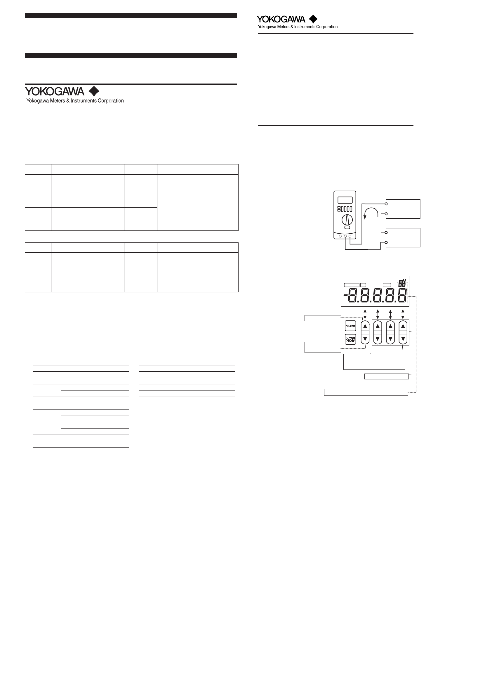
■ Calibration Precautions
• Connection for 20 mA SINK calibration
Connect the CA11E calibrator to the standard as shown below:
CA11E
H
DMM
current range
L
SINK
Lo
Hi
+
Constant-voltage
power supply
(Vo: 5-28V)
—
■ Assignment of Keys for Calibration
When the CA11E calibrator is in the calibration mode, keys are assigned as specified here.
20 mA
Standard DC
current generator
20 mA(4-20 mA) 20 mA ⫾0.02%/20 mA
■ Environmental Conditions for Calibration
Ambient temperature: 23 ⫾ 1°C
Relative humidity: 45 to 75% R.H
Warm-up: Warm-up time as specified for the standard
■ Calibration Points
• The calibration points are as specified in the following tables.
• It is possible to independently select the necessary range to be recalibrated.
• Always calibrate the zero (0) point and full scale (FS) as a pair for generation.
Source: Measurement:
Calibration points Standard Value
100 mV
1 V
10 V
30 V
20 mA
20 mA
SINK
*1: Make adjustments to CA11E according to the
reading of the standard (CA11E output Value)
as specified in the table.
00 mV
FS 100 mV
00 m V
FS 1000 mV
00 V
FS 10 V
00 V
FS 30 V
00 V
FS 20 mA
0.1 0.1 mA
FS 20 mA
Standard Value
*1
Calibration points
100 mV FS 100 mV
1 V FS 1 V
10 V FS 10 V
30 V FS 30 V
20 mA FS 20 mA
*2: Set the Value to the standard as specified in
the table.
■ Calibrating the Generation Feature
Operation procedure:
<1> Warm up the standard.
<2> Before turning on the power of the CA11E calibrator, connect it to the standard.
<3> Turn on the power of the instrument.
<4> Simultaneously press and hold the [▲1] and [▼4] keys (shown in the figure in the “Assign-
ment of Keys for Calibration” section below) for about 2 seconds to enter the calibration
mode.
<5> Select the generation range to calibrate using the MEASURE/SOURCE selection switch
and range selection rotary switch. The display unit shows “CAL,” “SOURCE,” “ON,” “0,” and
the lower limit.
<6> Read the output value of the CA11E using the standard (digital multimeter), and using the
[▲] and [▼] adjustment keys adjust the CA11E so that the output value is set to the offset
value. Then press the [▼1] input determination (ENTER) key to fix the setting.
After fixing the setting, the display unit reading changes to “CAL,” “SOURCE,” “ON,” “FS,”
and a full scale of the range.
<7> Read the output value of the CA11E using the standard (digital multimeter), and using the
[▲] and [▼] adjustment keys adjust the CA11E so that the output value is set to the full
scale value. Then press and hold the [▼1] input determination (ENTER) key for about 1
second to fix the setting.
After fixing the setting, the display unit shows “0 FS” blinking. Re-press and hold the [▼1]
input determination (ENTER) key for about 1 second to write the calibration coefficients to
the EEPROM of the instrument. (This overwrites the previous calibration coefficients.)
When this is complete, the instrument returns to the status in Step 5.
<8> Repeat Steps 5 to 7 for each range to be calibrated.
SOURCE
ON
Input cancellation key
Input determination
(ENTER) key
Mode switching (calibration or normal)
(Press and hold two keys
*2
Digit to be adjusted by the [▲4/▼4] adjustment keys
simultaneously for 2 seconds.)
Adjustment keys (six keys)
CAL
0
1234
■ Calibrating the Measurement Feature
Operation procedure:
<1> Warm up the standard.
<2> Before turning on the power of the CA11E calibrator, connect it to the standard.
<3> Turn on the power of the instrument.
<4> Simultaneously press and hold the [▲1] and [▼4] keys (shown in the figure in the “Assign-
ment of Keys for Calibration” section below) for about 2 seconds to enter the calibration
mode.
<5> Select the measurement range to calibrate using the MEASURE/SOURCE selection switch
and range selection rotary switch.
«CAL” and “MEASURE” appear and “FS” blinks on the display unit.
(If a value nearly equivalent to full scale has been input, a measured value and “FS”
appear.)
<6> Set up the standard in order to input the full scale value to the instrument. Wait until the
reading stabilizes, then press and hold the [▼1] input determination (ENTER) key for about
1 second to fix the setting.
<7> After fixing the setting, “0” and “FS” indications on the display unit start blinking. Re-press
and hold the [▼1] input determination (ENTER) key for about 1 second to write the calibration coefficients to the EEPROM of the instrument. (This overwrites the previous calibration
coefficients.)
<8> Repeat Steps 5 to 7 for each range to be calibrated.
To return to the previous step:
<9> To return to the previous step without fixing the setting, press the [▲1] input cancellation
key. Note that this is possible only before writing to the EEPROM.
To return to the normal operation mode:
<10>Simultaneously press and hold the [▲1] and [▼4] keys (shown in the figure in the “Assign-
ment of Keys for Calibration” section below) for about 2 seconds, or press the [POWER] key
to turn off the power once and then press it again to turn it back on.
IM CA11E-02E <1>
Normal setting:
<1> Switch the MEASURE/SOURCE selection switch to «SOURCE» (generation). This causes the
display unit to show «SOURCE» and «OFF.»
<2> Select the range to be generated using the range selection rotary switch.
The display unit shows an initial value and unit for each range.
<3> Press the [ ]/[ ] keys under the lower four digits to set an output value (5th digit: changes by
carry and borrow of the value from the 4th digit).
<4> Press the [OUTPUT ON/OFF] key to output a signal.
The display unit shows «ON.»
To stop the output, press the [OUTPUT ON/OFF] key again. This causes «OFF» to appear on
the display unit and the terminals to open.
Allowable load
The instrument should be used according to the maximum output and the maximum load range
(See Section 9, «Specifications»).
Current SINK (absorb) is only possible in the 20 mA SINK range.
1-5 V step output range
In the 1-5 V range, the [ ]/[ ] keys for the most significant digit can be used to step up or down by
1 V. For the lower three digits, these keys are used to increase or decrease the value of each digit
in increments of 1.
4-20 mA step output range
Use the range selection rotary switch to select 4-20 mA.
5-digit resolution
Set Dip Switch 3 to «OFF.»
Use the [ ]/[ ] keys under the upper one digit to change the value in increments of 4
mA: 4←→8←→12←→16←→20 mA.
For the lower three digits, these keys are used to increase or decrease the value of each
digit in increments of 1.
4-digit resolution
Set Dip Switch 3 to «ON.»
Use the [ ]/[ ] keys under the upper two digit to change the value in increments of 4
mA: 4←→8←→12←→16←→20 mA.
For the lower two digits, these keys are used to increase or decrease the value of each
digit in increments of 1.
For more information, see Subsection 7.2, «Switching Display Resolution.»
24 V (20 mA) range
In the 24 V output (20 mA measurement) range, the instrument can be used as a source of
constant voltage (24 V) to conduct a loop test of a transmitter.
Select «24 V (20 mA)» and SOURCE using the respective switches.
Press the [OUTPUT ON/OFF] key to set the output to «ON» (for 24 V DC output).
The display unit shows the current measurement and «SOURCE» (for 20 mA measurement).
20 mA SINK range
The instrument can absorb (SINK) a current with a specified value sent from an external voltage
generator (distributor) to the «Hi» terminal of the instrument. As the instrument serves as a two-wire
transmitter, it can be used for a loop test.
Select «20 mA SINK» and SOURCE using the respective switches.
Press the [OUTPUT ON/OFF] key to set the output to «ON.»
The display unit shows the set value (SINK) and «SOURCE.»
Uses an external power supply for 20 mA SINK in the range of 5-28 V.
The polarity of applied voltage should be as shown in the figures below. Be careful not to apply
voltage in the opposite direction.
24 V (20 mA) range
Two-wire transmitter
Transformer
+
4-20mA
—
Distributor
CA11E
Lo Hi
24V DC
Output limiter
If a load current in the voltage range or a load voltage in the current range exceeds the maximum
value specified in the specifications, the protective limiter is activated, turning off the output signal.
To recover from this condition, correct the load to normal status and press the [OUTPUT ON/OFF]
key to turn on output.
Sweep function
This function increases or decreases the output level to the preset level as a constant rate by
setting DIP switch 1 to ON. For more information, see Subsection 7.1, «Sweep Function.»
6. Measurement
When connecting the device under measurement, turn off the power of the device.
Connecting/disconnecting the lead cables for measurement without turning off the power
of the device under measurement may be extremely dangerous.
Special care should be taken to avoid connecting a current circuit to the voltage input
terminals or a voltage circuit to the current input terminals. Inadvertent connection may
not only cause damage to the circuit or device under measurement and the instrument,
but may also be dangerous to personnel.
Always use the lead cables supplied with the instrument.
Maximum allowable voltage between all input/output terminals and ground is 30 V DC.
Any voltage exceeding this level may not only damage the instrument, but also cause
injury to personnel. Never attempt to apply such voltage.
Do not apply voltage exceeding the maximum allowable input voltage to the voltage input
terminals. This may damage the instrument.
Maximum input voltage: 30 V DC
Do not apply current exceeding the maximum allowable input current to the current input
terminals. If current exceeding this level is applied, built-in fuses for protecting the
current input circuit will burn out. If a fuse burns out, contact us for repair.
Maximum input current: 24 mA
6.1 Connecting Procedure
<1> Insert the plugs of the supplied lead cables into the terminals of the CA11E as shown in figure
«a» below for voltage or in figure «b» below for current.
<2> Connect the clips on the other ends to the input terminals of the device under measurement.
a. Connection of the
voltage input terminals
INPUT V
Hi
Lo
Hi
+
—
20 mA SINK range
Two-wire transmitter
Transformer
+
4-20mA
—
Distributor
CA11E
Lo Hi
WARNING
CAUTION
b. Connection of the
current input terminals
INPUT mA
Hi
Lo
Hi
—
+
6.2 Measuring DC Voltage and DC Current
<1> Switch the MEASURE/SOURCE selection switch to MEASURE (measurement).
MEASURE lights up on the display unit.
<2> Select the range to be measured using the range selection rotary switch.
• The display unit shows the measurement results and unit. Indication of the measurement results
will be updated approximately every second.
• If an input signal is over range or not measurable, the display unit shows «—-.»
• For invalid ranges, terminal-to-terminal connection becomes open, causing the display unit to
show «-nC-» and «OFF.»
Input limiter
If voltage is applied to the current input terminals or excessive current is applied to them, the
internal protective circuit is activated, opening the terminal-to-terminal connection and causing the
display unit to show «OFF.»
In this case, check that the connection is correct and press the [INPUT ON] key (= [OUTPUT ON/
OFF] key). This causes the OFF indication to disappear and measurement to resume.
7. Other Features
The following features are available depending on the settings of the DIP switches, which can be
accessed by removing the cover from the back of the instrument.
DIP switches
ON
1: Sweep function
2: Sweep time (OFF: 16 sec. / ON: 32 sec.)
3: Current display resolution (OFF: 5 digits / ON: 4 digits)
4: Disable automatic power off
1
2
3
4
7.1 Sweep Function
By setting DIP switch 1 to ON, the output level can be increased or decreased to the preset level at
a constant rate. This function cannot be used in the 24 V (20 mA) range.
Output status transition diagram
Set value
High impedance
Lower range limit
Sweep status
(A)
(B)
(C)
Operation of
↑
OUTPUT
(↑)
ON/OFF key
Operation procedure
<1> Turn on DIP switch 1.
<2> Use DIP switch 2 to select sweeping time (16 or 32 seconds)
<3> Set the MEASURE/SOURCE selection switch to SOURCE. The display unit shows
«SOURCE,» «OFF,» «SP,» and lower limit (initial value).
<4> Use the [ ]/[ ] keys to preset the upper limit for output in the same way as for normal
signal generation (Status A above).
<5> Press the [OUTPUT ON/OFF] key.
(B) The display unit shows «ON» and a lower limit (initial value) for 2 seconds, and the
instrument outputs that value.
(C) Then the reading on the display unit and the output level automatically increase to
the upper limit set in Step <4> at the constant sweep time rate set in Step <2>.
The display unit shows the «ON» light blinking.
In this case, if you press the [OUTPUT ON/OFF] key again, the reading and the
output level will start decreasing from that value at a constant rate. The output status
changes to Status E (shown by dotted-lines in the figure).
(D) When the reading and the output level reach the set values, they remain at these
levels until the [OUTPUT ON/OFF] key is pressed.
The display unit’s «ON» light comes on.
In this case, if you press the [OUTPUT ON/OFF] key, the reading and the output
level start decreasing from that value at a constant rate. The output status changes
to Status E.
(E) Then the reading and the output level automatically decrease to the set lower limits
at the constant sweep time rate set in Step <1>.
The display unit shows the «OFF» light blinking.
In this case, if you press the [OUTPUT ON/OFF] key again, the reading and the
output level start increasing from that value at a constant rate.
The output status changes to Status C (shown by dotted-lines in the figure).
(F) Then the reading and the output level reach the lower limits and remain at these
levels for 3 seconds. The display unit’s «ON» light comes on.
<6> Return to Step <4>.
Canceling the sweep function
<7> Open the cover at the back of the instrument and set DIP switch 1 to off.
7.2 Switching Display Resolution
By changing the setting of DIP switch 3, the display resolution (5 digit/4 digit) can be selected.
The available ranges are as follows:
SOURCE:
20 mA, 4-20 mA, 24 V (20 mA), 20 mA SINK
MEASURE: 20 mA, (4-20 mA)
<Example 4-20 mA ranges>
5-digit range
7.3 Disabling Automatic Power Off
According to the factory setting of the instrument, it automatically turns itself off if not operated for
about 10 minutes. By setting DIP switch 4 to «ON,» this function can be disabled.
However, when the instrument is battery-driven, it is generally recommended that this switch be
set to «OFF» in order to prevent the batteries from being exhausted.
(D)
(E)
(F)
(A)
↑
(↑)
4-digit range
IM CA11E-01E <2>
|
Detail Specifications: 1687/1687366-ca11e_handy_cal.pdf file (29 Nov 2022) |
Accompanying Data:
YOKOGAWA CA11E HANDY CAL Test Equipment PDF Operation & User’s Manual (Updated: Tuesday 29th of November 2022 06:22:56 AM)
Rating: 4.6 (rated by 72 users)
Compatible devices: 701985 Series, CA320, CA150, DLM4038, MY10-01, CA500, DLM2000 Series, 720930.
Recommended Documentation:
Text Version of Operation & User’s Manual
(Ocr-Read Summary of Contents, UPD: 29 November 2022)
-
1, YOKOGAWA CA11E HANDY CAL IM CA11E-02E <Page 1> ■ Calibration the Generation Feature Operation procedure: <1> Warm up the standard. <2> Before turning on the power of the CA11E calibrator, connect it to the standard. <3> Turn on the power of the instrument. <4> Simultaneously press and hold the keys (shown in the gure in the “Assignment of Keys for Calibrat…
-
2, IM CA11E-02E <Page 2> 10. How to Use the Carrying Case and Rubber Boot ■ Carrying case (B9108NK) The carrying case (B9108NK) may be used as follows: (1) Undo the fasteners on the top and sides of the case cover to open it. (2) With the fastener on the logo-side of the case centered, lift the cover and pivot it to the side and under the case itself. (3) R…
Recommended Instructions:
PASSPORT 300 PRO, 9116LP, ESL 988, SR6850HW4M, UL 127


-
1 INSTRUMENTS _______________________________________________________________________________________ Portable test kits based on the Palintest Pooltest 25 Photometer are available in a variety of formats including the Palintest Pooltest 25 MiniLab which contains the equipment and reagents for pool testing in a moulded plastic work-tray. …
Pooltest 25 Professional Plus 14
-
OMHACM415250OPERATINGMANUALforACLOADBANKtypeHACM415250Xissue1SerialNo.M372051 …
HACM415250X 14
-
BuzzerFuseAuto shut offGroundingACDouble InsulationRelative MeasurementWarningDCDiodeRange600mV 0.1mV0.001V0.01V0.1V1V6V60V600V1000VResolution Accuracy±(0.5%+4)±(0.5%+2)±(0.7%+10)Range600Ω 0.1Ω0.001kΩ0.01kΩ0.1kΩ0.001MΩ0.01MΩ6kΩ60kΩ600kΩ6MΩ60MΩResolutionAccuracy±(0.8%+5)±(0.8%+3)±(1.0%+25) Operating ManualI. General Introduction This brand new UT890C+/D …
UT890D 2
Additional Information:
Operating Impressions, Questions and Answers:
YOKOGAWA CA11E (01) PDF MANUAL
Click here to download YOKOGAWA CA11E (01) PDF MANUAL
YOKOGAWA CA11E (01) PDF MANUAL
FREE ENGLISH PDF
OPERATING INSTRUCTIONS
USER GUIDE – USER MANUAL
OWNER GUIDE – OWNER MANUAL
REFERENCE GUIDE – REFERENCE MANUAL
INSTRUCTION GUIDE – INSTRUCTION MANUAL
Your overall rating
Title of your review
Your review
Your name
Your email
This review is based on my own experience and is my genuine opinion.
YOKOGAWA CA11E (01) PDF MANUAL
YOKOGAWA CA11E (01) PDF MANUAL
Leave a comment, question, review or page error below. Account not required.
This site uses Akismet to reduce spam. Learn how your comment data is processed.