инструкцияMSI Z370-A Pro

1
Unpacking
Unpacking
Thank you for buying the MSI
®
Z370-A PRO motherboard. Check to make sure your
motherboard box contains the following items. If something is missing, contact your
dealer as soon as possible.
SATA Cable x2
Drivers & Utilities
Disc
Motherboard User
Guide
I/O Shield
Motherboard
Посмотреть инструкция для MSI Z370-A Pro бесплатно. Руководство относится к категории материнские платы, 5 человек(а) дали ему среднюю оценку 8.7. Руководство доступно на следующих языках: английский. У вас есть вопрос о MSI Z370-A Pro или вам нужна помощь? Задайте свой вопрос здесь
- Unpacking
- Safety Information
- Quick Start
- Specifications
- Block Diagram
- Rear I/O Panel
- Overview of Components
- BIOS Setup
- Software Description
- RAID Configuration
- Intel® Optane™ Memory Configuration
- Troubleshooting
- Regulatory Notices
- CPU_FAN1,SYS_FAN1~4, PUMP_FAN1: Fan Connectors
- CPU_PWR1, ATX_PWR1: Power Connectors
- CPU Socket
- DIMM Slots
- JAUD1: Front Audio Connector
- JBAT1: Clear CMOS (Reset BIOS) Jumper
- JCI1: Chassis Intrusion Connector
- JCOM1: Serial Port Connector
- JFP1, JFP2: Front Panel Connectors
- JLPT1: Parallel Port Connector
- JTBT1: Thunderbolt Add-on Card Connector
- JTPM1: TPM Module Connector
- JUSB1~2: USB 2.0 Connectors
- JUSB3~4: USB 3.1 Gen1 Connectors
- M2_1: M.2 Slot (Key M)
- PCI_E1~6: PCIe Expansion Slots
- SATA1~6: SATA 6Gb/s Connectors
Главная
| MSI | |
| Z370-A Pro | 7B48-001R | |
| материнская плата | |
| 4719072540395, 0824142152942 | |
| английский | |
| Руководство пользователя (PDF) |
Память
| Поддерживаемые типы памяти | DDR4-SDRAM |
| Тип слотов памяти | DIMM |
| Количество слотов памяти | 4 |
| Каналы памяти | Dual-channel |
| Error-correcting code (ECC) | Нет |
| без функции коррекции ошибок | Да |
| Поддерживаемые частоты памяти | 2133,4000 MHz |
| Максимальная внутренняя память | 64 GB |
| Небуферизованная память | Да |
Контроллеры хранения данных
| Поддерживаемые типы накопителей | HDD & SSD |
| Поддерживаемые интерфейсы носителя | M.2, SATA III |
| Уровни RAID | 0, 1,5, 10 |
Особые свойства процессора
| экстремальный профиль памяти Intel | Да |
| Intel® Optane™ Memory Ready | Да |
Свойства
| Поддерживаемые операционные системы Windows | Да |
| Мониторинг состояния ПК | CPU, FAN, Power supply, Temperature, Voltage |
| Тип охлаждения | Пассивный |
| Комплектующие для | ПК |
| Семейство чипсета материнской платы | Intel |
| Чипсет материнской платы | — |
| Формат материнской платы | ATX |
| Выходные звуковые каналы | 7.1 канала |
| Аудио чип | Realtek ALC892 |
| Тип источника питания | ATX |
Графический адаптер
| Семейство графического адаптера | Intel |
| Поддержка выделеной видео карты | Да |
| Поддержка технологии параллельной обработки | 2-Way CrossFireX |
Процессор
| Производитель процессора | Intel |
| Совместимые серии процессоров | Intel Celeron, Intel Pentium |
| Сокет процессора | LGA 1151 (разъем H4) |
| Максимальное число процессоров для SMP | 1 |
| Поддерживаемые сокеты процессоров | LGA 1151 (разъем H4) |
Внутренние порты
| Число коннекторов SATA | 6 |
| Разъем вентилятора центрального процессора | Да |
| Разъем питания ATX (24-конт.) | Да |
| Количество параллельных разъемов ATA (PATA) | 0 |
| Количество разъемов SATA II | 0 |
| Количество разъемов SATA III | 6 |
| Разъемы USB 3.2 Gen 1 (3.1 Gen 1) | 2 |
| Разъемы USB 2.0 | 2 |
| Разъемы USB 3.2 Gen 2 (3.1 Gen 2) | 0 |
| Разъем Chassis intrusion | Да |
| Количество разъемов вентилятора корпуса | 4 |
| EPS разъем питания (8-конт) | Да |
| TPM коннектор | Да |
| Аудиоразъем передней панели | Да |
| Коннекторы последовательного порта | 1 |
| разъемы Thunderbolt | 1 |
| Разъем передней панели | Да |
BIOS
Сеть
| Подключение Ethernet | Да |
| Тип Ethernet интерфейса | Гигабитный Ethernet |
| Контроллер LAN | Realtek RTL8111H |
Вес и размеры
| Глубина | — mm |
| Высота | 305 mm |
| Ширина | 244 mm |
Содержимое упаковки
| Поставляемые кабели | SATA |
| Драйвера в комплекте | Да |
Прочие свойства
| Краткое руководство по установке | Да |
| Последовательный порт через внутренний разъем | Да |
| параллельный порт через внутренний разъем | Да |
Слоты расширения
| Слоты PCI Express x1 (поколение 3.x) | 4 |
| Слоты PCI Express x16 (поколение 3.x) | 2 |
| Количество M.2 (M) слотов | 1 |
Порты на задней панели
| Количество портов PS/2 | 1 |
| Количество портов VGA (D-Sub) | 1 |
| Количество портов DVI-D | 1 |
| Количество HDMI портов | 0 |
| Порты FireWire | 0 |
| Количество портов DisplayPort | 1 |
| Линейные выходы наушников | 1 |
| Линейный вход микрофона | Да |
| Количество портов eSATA | 0 |
| Количество портов Ethernet LAN ( RJ-45) | 1 |
| Количество портов USB 2.0 | 2 |
| Количество портов USB 3.2 Gen 1 (3.1 Gen 1) Type-A | 4 |
| Количество портов USB 3.2 Gen 1 (3.1 Gen 1) Type-С | 0 |
| Количество портов USB 3.2 Gen 2 (3.1 Gen 2) Type-A | 0 |
| Количество портов USB 3.2 Gen 2 (3.1 Gen 2) Type-С | 0 |
показать больше
Не можете найти ответ на свой вопрос в руководстве? Вы можете найти ответ на свой вопрос ниже, в разделе часто задаваемых вопросов о MSI Z370-A Pro.
Какая высота MSI Z370-A Pro?
Какая ширина MSI Z370-A Pro?
Какая толщина MSI Z370-A Pro?
Инструкция MSI Z370-A Pro доступно в русский?
Не нашли свой вопрос? Задайте свой вопрос здесь
- Manuals
- Brands
- MSI Manuals
- Motherboard
- Z370-A PRO
- User manual
-
Contents
-
Table of Contents
-
Troubleshooting
-
Bookmarks
Quick Links
Unpacking
Thank you for buying the MSI
Z370-A PRO
motherboard. Check to make sure your
®
motherboard box contains the following items. If something is missing, contact your
dealer as soon as possible.
Drivers & Utilities
Motherboard User
Disc
Guide
Motherboard
I/O Shield
SATA Cable x2
1
Unpacking
Related Manuals for MSI Z370-A PRO
Summary of Contents for MSI Z370-A PRO
-
Page 1: Unpacking
Unpacking Thank you for buying the MSI Z370-A PRO motherboard. Check to make sure your ® motherboard box contains the following items. If something is missing, contact your dealer as soon as possible. Drivers & Utilities Motherboard User Disc Guide…
-
Page 2: Safety Information
Safety Information y The components included in this package are prone to damage from electrostatic discharge (ESD). Please adhere to the following instructions to ensure successful computer assembly. y Ensure that all components are securely connected. Loose connections may cause the computer to not recognize a component or fail to start.
-
Page 3: Quick Start
Quick Start Preparing Tools and Components Intel LGA 1151 CPU ® CPU Fan Thermal Paste DDR4 Memory Power Supply Unit Chassis SATA Hard Disk Drive Graphics Card SATA DVD Drive A Package of Screws Phillips Screwdriver Quick Start…
-
Page 4: Installing A Processor
Installing a Processor http://youtu.be/bf5La099urI Quick Start…
-
Page 5: Installing Ddr4 Memory
Installing DDR4 memory http://youtu.be/T03aDrJPyQs DIMMB2 DIMMB2 DIMMB1 DIMMA2 DIMMA2 DIMMA2 DIMMA1 Quick Start…
-
Page 6: Connecting The Front Panel Header
Connecting the Front Panel Header http://youtu.be/DPELIdVNZUI HDD LED + Power LED + HDD LED — Power LED — Reset Switch Power Switch Reset Switch Power Switch JFP1 Reserved No Pin JFP1 HDD LED — HDD LED HDD LED + POWER LED — POWER LED POWER LED + Quick Start…
-
Page 7: Installing The Motherboard
Installing the Motherboard Quick Start…
-
Page 8: Installing Sata Drives
Installing SATA Drives http://youtu.be/RZsMpqxythc Quick Start…
-
Page 9: Installing A Graphics Card
Installing a Graphics Card http://youtu.be/mG0GZpr9w_A Quick Start…
-
Page 10: Connecting Peripheral Devices
Connecting Peripheral Devices Quick Start…
-
Page 11: Connecting The Power Connectors
Connecting the Power Connectors http://youtu.be/gkDYyR_83I4 ATX_PWR1 CPU_PWR1 Quick Start…
-
Page 12: Power On
Power On Quick Start…
-
Page 13: Table Of Contents
Contents Unpacking ………………….1 Safety Information ………………..2 Quick Start ………………….3 Preparing Tools and Components …………….3 Installing a Processor ………………… 4 Installing DDR4 memory ………………5 Connecting the Front Panel Header …………… 6 Installing the Motherboard ………………7 Installing SATA Drives…………………
-
Page 14
Installing Utilities ………………..63 APP MANAGER ………………… 64 LIVE UPDATE 6 …………………. 65 COMMAND CENTER ………………… 67 X-BOOST ………………….. 71 MYSTICLIGHT ………………….73 MSI SMART TOOL ………………..75 RAMDISK………………….. 77 NETWORK GENIE ………………..78 Intel Extreme Tuning Utility …………….80 ®… -
Page 15: Specifications
Supports Intel Extreme Memory Profile (XMP) ® *Please refer to www.msi.com for more information on compatible memory. y 1x PCIe 3.0 x16 slot (PCI_E1, supports x16 mode) Expansion Slots y 1x PCIe 3.0 x16 slot (PCI_E4, supports x4 mode) y 4x PCIe 3.0 x1 slots…
-
Page 16
Continued from previous page Intel Z370 Chipset ® RAID y Supports RAID 0, RAID 1, RAID 5 and RAID 10 for SATA storage devices y Intel Z370 Chipset ® ƒ 8x USB 3.1 Gen1 (SuperSpeed USB) ports (4 Type-A ports on the back panel, 4 ports available through the internal USB connectors) ƒ… -
Page 17
Continued from previous page y 1x 24-pin ATX main power connector y 1x 8-pin ATX 12V power connector y 6x SATA 6Gb/s connectors y 2x USB 3.1 Gen1 connectors (supports additional 4 USB 3.1 Gen1 ports) y 2x USB 2.0 connectors (supports additional 4 USB 2.0 ports) y 1x 4-pin CPU fan connector y 1x 4-pin water pump fan connector… -
Page 18
Continued from previous page y Drivers y APP MANAGER y SUPER CHARGER y COMMAND CENTER y LIVE UPDATE 6 y MSI SMART TOOL y RAMDISK Software y DPC Latency Tuner y FAST BOOT y X-BOOST y MYSTIC LIGHT y NETWORK GENIE… -
Page 19
Continued from previous page y Audio ƒ Audio Boost y Network ƒ Realtek LAN with Network Genie y Storage ƒ Turbo M.2 y Fan ƒ Pump Fan ƒ Smart Fan Control y LED ƒ Mystic Light ƒ Mystic light SYNC ƒ… -
Page 20: Block Diagram
Block Diagram DVI-D DisplayPort 2 Channel DDR4 Memory PCI Express Bus DMI 3.0 PCIe x1 slot PCIe x1 slot 1 x M.2 PCIe x1 slot PCIe x1 slot 6 x SATA 6Gb/s Z370 8 x USB 3.1 Gen1 6 x USB 2.0 LPC Bus NV6795 Realtek…
-
Page 21: Rear I/O Panel
Rear I/O Panel Audio Ports PS/2 Port USB 3.1 Gen1 DisplayPort USB 2.0 USB 3.1 Gen1 DVI-D LAN Port LED Status Table Link/ Activity LED Speed LED Status Description Status Description No link 10 Mbps connection Yellow Linked Green 100 Mbps connection Blinking Data activity Orange…
-
Page 22: Realtek Hd Audio Manager
Realtek HD Audio Manager After installing the Realtek HD Audio driver, the Realtek HD Audio Manager icon will appear in the system tray. Double click on the icon to launch. Device Selection Advanced Settings Jack Status Application Enhancement Main Volume Connector Strings Profiles…
-
Page 23
Audio jacks to headphone and microphone diagram Audio jacks to stereo speakers diagram AUDIO INPUT Audio jacks to 7.1-channel speakers diagram AUDIO INPUT Front Center/ Subwoofer Side Rear Rear I/O Panel… -
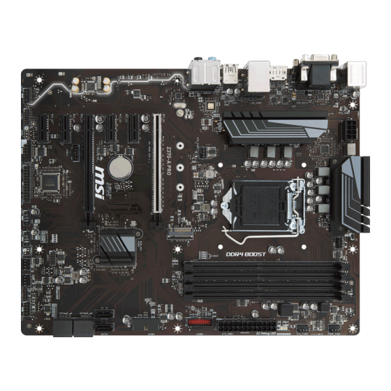
Page 24: Overview Of Components
Overview of Components DIMMA1 SYS_FAN4 DIMMA2 CPU_FAN1 CPU_PWR1 DIMMB1 DIMMB2 CPU Socket PUMP_FAN1 SYS_FAN2 EZ Debug LED ATX_PWR1 JUSB3 JBAT1 M2_1 PCI_E1 JUSB4 PCI_E2 SATA2 PCI_E3 SATA1 PCI_E4 SATA▼3▲4 JTBT1 PCI_E5 SATA▼5▲6 PCI_E6 JCI1 JAUD1 JFP1 JTPM1 JFP2 SYS_FAN3 JCOM1 SYS_FAN1 JLPT1 JUSB1…
-
Page 25
Component Contents Port Name Port Type Page CPU_FAN1,SYS_FAN1~4, PUMP_FAN1 Fan Connectors CPU_PWR1, ATX_PWR1 Power Connectors CPU Socket LGA1151 CPU Socket DIMMA1/ A2/ B1/ B2 DIMM Slots JAUD1 Front Audio Connector Clear CMOS (Reset BIOS) JBAT1 Jumper JCI1 Chassis Intrusion Connector JCOM1 Serial Port Connector JFP1, JFP2… -
Page 26: Cpu Socket
Always unplug the power cord from the power outlet before installing or removing the CPU. Please retain the CPU protective cap after installing the processor. MSI will deal with Return Merchandise Authorization (RMA) requests if only the motherboard comes with the protective cap on the CPU socket.
-
Page 27: Dimm Slots
DIMM Slots DIMMA1 DIMMB1 Channel A Channel B DIMMA2 DIMMB2 Memory module installation recommendation DIMMB2 DIMMB2 DIMMB1 DIMMA2 DIMMA2 DIMMA2 DIMMA1 Important Always insert memory modules in the DIMMA2 slot first. Due to chipset resource usage, the available capacity of memory will be a little less than the amount of installed.
-
Page 28: Pci_E1~6: Pcie Expansion Slots
If you install a large and heavy graphics card, you need to use a tool such as MSI Gaming Series Graphics Card Bolster to support its weight and to prevent deformation of the slot. Overview of Components…
-
Page 29: M2_1: M.2 Slot (Key M)
M2_1: M.2 Slot (Key M) Important Intel Optane Memory Ready. ® Video Demonstration Watch the video to learn how to Install M.2 module. http://youtu.be/JCTFABytrYA Installing M.2 module 1. Remove the screw from the base screw. 2. Remove the base screw. 3.
-
Page 30: Sata1~6: Sata 6Gb/S Connectors
SATA1~6: SATA 6Gb/s Connectors These connectors are SATA 6Gb/s interface ports. Each connector can connect to one SATA device. SATA2 SATA1 SATA4 SATA3 SATA6 SATA5 Important The SATA1 port will be unavailable when an M.2 SATA SSD module has been installed in the M.2 slot.
-
Page 31: Cpu_Pwr1, Atx_Pwr1: Power Connectors
CPU_PWR1, ATX_PWR1: Power Connectors These connectors allow you to connect an ATX power supply. CPU_PWR1 Ground +12V Ground +12V Ground +12V Ground +12V +3.3V +3.3V +3.3V -12V Ground Ground PS-ON# Ground Ground Ground ATX_PWR1 Ground Ground PWR OK 5VSB +12V +12V +3.3V Ground…
-
Page 32: Jusb1~2: Usb 2.0 Connectors
JUSB1~2: USB 2.0 Connectors These connectors allow you to connect USB 2.0 ports on the front panel. USB0- USB1- USB0+ USB1+ Ground Ground No Pin Important Note that the VCC and Ground pins must be connected correctly to avoid possible damage.
-
Page 33
However, when you boot the computer into Windows ® you will need to install the MSI SUPER CHARGER application to turn ON/OFF the ®… -
Page 34: Cpu_Fan1,Sys_Fan1~4, Pump_Fan1: Fan Connectors
CPU_FAN1,SYS_FAN1~4, PUMP_FAN1: Fan Connectors Fan connectors can be classified as PWM (Pulse Width Modulation) Mode or DC Mode. PWM Mode fan connectors provide constant 12V output and adjust fan speed with speed control signal. DC Mode fan connectors control fan speed by changing voltage. When you plug a 3-pin (Non-PWM) fan to a fan connector in PWM mode, the fan speed will always maintain at 100%, which might create a lot of noise.
-
Page 35: Jaud1: Front Audio Connector
JAUD1: Front Audio Connector This connector allows you to connect audio jacks on the front panel. MIC L Ground MIC R Head Phone R MIC Detection SENSE_SEND No Pin Head Phone L Head Phone Detection JCI1: Chassis Intrusion Connector This connector allows you to connect the chassis intrusion switch cable. Normal Trigger the chassis intrusion event…
-
Page 36: Jtpm1: Tpm Module Connector
JTPM1: TPM Module Connector This connector is for TPM (Trusted Platform Module). Please refer to the TPM security platform manual for more details and usages. LPC Clock 3V Standby power LPC Reset 3.3V Power LPC address & data pin0 Serial IRQ LPC address &…
-
Page 37: Jbat1: Clear Cmos (Reset Bios) Jumper
JBAT1: Clear CMOS (Reset BIOS) Jumper There is CMOS memory onboard that is external powered from a battery located on the motherboard to save system configuration data. If you want to clear the system configuration, set the jumper to clear the CMOS memory. Keep Data Clear CMOS/ Reset BIOS…
-
Page 38: Ez Debug Led
EZ Debug LED These LEDs indicate the status of key components during booting process. When an error is occurred, the corresponding LED stays lit until the problem is solved. CPU — indicates CPU is not detected or fail. DRAM — indicates DRAM is not detected or fail. VGA — indicates GPU is not detected or fail.
-
Page 39: Bios Setup
Press Delete key, when the Press DEL key to enter Setup Menu, F11 to enter Boot Menu message appears on the screen during the boot process. y Use MSI FAST BOOT application. Click on GO2BIOS button and choose OK. The system will reboot and enter BIOS setup directly.
-
Page 40: Resetting Bios
Updating BIOS Updating BIOS with M-FLASH Before updating: Please download the latest BIOS file that matches your motherboard model from MSI website. And then save the BIOS file into the USB flash drive. Updating BIOS: 1. Press Del key to enter the BIOS Setup during POST.
-
Page 41: Ez Mode
EZ Mode At EZ mode, it provides the basic system information and allows you to configure the basic setting. To configure the advanced BIOS settings, please enter the Advanced Mode by pressing the Setup Mode switch or F7 function key. XMP switch Setup Mode switch Screenshot…
-
Page 42
y Information display — click on the CPU, Memory, Storage, Fan Info and Help buttons on left side to display related information. y Function buttons — enable or disable the LAN Option ROM, M.2/ Optane Genie, HD audio controller, AHCI, RAID, CPU Fan Fail Warning Control and BIOS Log Review by clicking on their respective button. -
Page 43: Advanced Mode
Advanced Mode Press Setup Mode switch or F7 function key can switch between EZ Mode and Advanced Mode in BIOS setup. XMP switch Setup Mode switch Screenshot Search Language System information OC GENIE 4 switch Boot device priority bar BIOS menu BIOS menu selection selection…
-
Page 44: Settings
SETTINGS System Status f System Date Sets the system date. Use tab key to switch between date elements. The format is <day> <month> <date> <year>. <day> Day of the week, from Sun to Sat, determined by BIOS. Read-only. <month> The month from Jan. through Dec. <date>…
-
Page 45
fPEG X — Max Link Speed [Auto] Sets PCI Express protocol of PCIe x16 slots for matching different installed devices. [Auto] This item will be configured automatically by BIOS. [Gen1] Enables PCIe Gen1 support only. [Gen2] Enables PCIe Gen2 support only. [Gen3] Enables PCIe Gen3 support only. -
Page 46
fIpv6 PXE Support [Enabled] When Enabled, the system UEFI network stack will support Ipv6 protocol. This item will appear when Network Stack is enabled. [Enabled] Enables the Ipv6 PXE boot support. [Disabled] Disables the Ipv6 PXE boot support. fSATA Mode [AHCI Mode] Sets the operation mode of the onboard SATA controller. -
Page 47
fUSB Controller [Enabled] Enables or disables all USB controller. fXHCI Hand-off [Diasbled] Enables or disables XHCI hand-off support for the operating system without XHCI hand-off feature. fLegacy USB Support [Enabled] Sets Legacy USB function support. [Auto] The system will automatically detect if any USB device is connected and enable the legacy USB support. -
Page 48
Disables this function. fMSI Fast Boot [Disabled] MSI Fast Boot is the fastest way to boot the system. It will disable more devices to speed up system boot time which is faster than the boot time of Fast Boot. [Enabled] Enables the MSI Fast Boot function to speed up booting time. -
Page 49
fInternal GOP Configuration Manages the onboard Graphics Output Protocol (GOP). Press Enter to enter the sub-menu. This sub-menu will appear when Windows 10 WHQL Support is enabled. fSecure Boot Sets the Windows secure boot to prevent the unauthorized accessing. Press Enter to enter the sub-menu. -
Page 50: Boot
fResume by USB Device [Disabled] Enables or disables the system wake up by USB devices. [Enabled] Enables the system to be awakened from sleep state when activity of USB device is detected. [Disabled] Disables this function. fResume From S3/S4/S5 by PS/2 Mouse [Disabled] Enables or disables the system wake up by PS/2 mouse.
-
Page 51: Security
f Info Block effect [Unlock] Sets the state of Help information block. [Unlock] Sliding effect. [Lock] Fix the Help information block on the screen. f AUTO CLR_CMOS [Disabled] Enables or disables the CMOS data to be resumed automatically when the booting process hang-up over 5 seconds.
-
Page 52: Save & Exit
Important When selecting the Administrator / User Password items, a password box will appear on the screen. Type the password then press <Enter>. The password typed now will replace any previous set password from CMOS memory. You will be prompted to confirm the password.
-
Page 53
Important Overclocking your PC manually is only recommended for advanced users. Overclocking is not guaranteed, and if done improperly, it could void your warranty or severely damage your hardware. If you are unfamiliar with overclocking, we advise you to use OC GENIE 4 function for easy overclocking. -
Page 54
f CPU Ratio Mode [Dynamic Mode]* Selects the CPU Ratio operating mode. This item will appear when you set the CPU ratio manually. [Fixed Mode] Fixes the CPU ratio. [Dynamic Mode] CPU ratio will be changed dynamically according to the CPU loading. -
Page 55
f CPU Base Clock Apply Mode [Auto]* Sets the applying mode for adjusted CPU base clock. [Auto] This setting will be configured automatically by BIOS. [Next Boot] CPU will run the adjusted CPU base clock at next boot. [Immediate] CPU runs the adjusted CPU base clock immediately. [During Boot] CPU will run the adjusted CPU base clock during boot. -
Page 56
fCPU GT Loadline Calibration Control [Auto] The voltage of the GPU embeeded in CPU will decrease proportionally according to GPU loading. Higher load-line calibration could get higher voltage and good overclocking performance, but increase the temperature of the CPU and VRM. f CPU Core/ GT Voltage Mode [Auto]* Selects the control mode for CPU Core/ GT voltages. -
Page 57
f CPU Features Press Enter to enter the sub-menu. fHyper-Threading [Enabled] Intel Hyper-Threading technology treats the multi cores inside the processor as multi logical processors that can execute instructions simultaneously. In this way, the system performance is highly improved. This item appears when the installed CPU supports this technology. -
Page 58
fIntel Adaptive Thermal Monitor [Enabled] Enables or disables the Intel adaptive thermal monitor function to protect the CPU from overheating. [Enabled] Throttles down the CPU core clock speed when the CPU is over the adaptive temperature. [Disabled] Disables this function. fIntel C-State [Auto] Enables or disables the Intel C-state. -
Page 59
fLong Duration Power Limit (W) [Auto] Sets the long duration TDP power limit for CPU in Turbo Boost mode. fLong Duration Maintained (s) [Auto] Sets the maintaining time for Long duration power Limit(W). fShort Duration Power Limit (W) [Auto] Sets the short duration TDP power limit for CPU in Turbo Boost mode. fCPU Current Limit (A) [Auto] Sets maximum current limit of CPU package in Turbo Boost mode. -
Page 60: M-Flash
M-FLASH provides the way to update BIOS with a USB flash drive. Please down-load the latest BIOS file that matches your motherboard model from MSI website, save the BIOS file into your USB flash drive. And then follow the steps below to update BIOS.
-
Page 61: Oc Profile
OC PROFILE f Overclocking Profile 1/ 2/ 3/ 4/ 5/ 6 Overclocking Profile 1/ 2/ 3/ 4/ 5/ 6 management. Press <Enter> to enter the sub- menu. fSet Name for Overclocking Profile 1/ 2/ 3/ 4/ 5/ 6 Name the current overclocking profile. fSave Overclocking Profile 1/ 2/ 3/ 4/ 5/ 6 Save the current overclocking profile.
-
Page 62: Hardware Monitor
HARDWARE MONITOR Temperature & Speed Fan Manage Setting Buttons Voltage display f Temperature & Speed Shows the current CPU temperature, system temperature and fans’ speeds. f Fan Manage ƒ PWM — allows you to select the PWM mode for fan operation. ƒ…
-
Page 63: Software Description
Software Description Please download and update the latest utilities and drivers at www.msi.com Installing Windows ® 1. Power on the computer. 2. Insert the Windows 10 disc into your optical drive. ® 3. Press the Restart button on the computer case.
-
Page 64: App Manager
Motherboard Information — shows the model name of motherboard. y Total Install/ Update — click on this tab to update/ install all the applications. Important Please note that, once you uninstall the APP MANAGER, all the MSI applications and software will be uninstalled simultaneously. Software Description…
-
Page 65: Live Update 6
LIVE UPDATE 6 LIVE UPDATE 6 is an application for the MSI system to scan and download the latest ® drivers, BIOS and utilities. With LIVE UPDATE 6, you don’ t need to search the drivers on websites, and don’ t need to know the models of motherboard and graphics cards.
-
Page 66
1. Select the Live Update tab. 2. Choose Automatic scan, system will automatically scan all the items and search for the latest update files. Or you can choose Manual scan and select the items you wish to scan. 3. Click the Scan button at the bottom. It may take several moments to complete the process. -
Page 67: Command Center
COMMAND CENTER COMMAND CENTER is an user-friendly software and exclusively developed by MSI, helping users to adjust system settings and monitor status under OS. With the help of COMMAND CENTER, making it possible to achieve easier and efficient monitoring process and adjustments than that under BIOS. In addition, the COMMAND CENTER can be a server for mobile remote control application.
-
Page 68
CPU Fan CPU Fan control panel provides Smart mode and Manual Mode. You can switch the control mode by clicking the Smart Mode and Manual Mode buttons on the top of the CPU Fan control panel. y Manual Mode — allows you to manually control the CPU fan speed by percentage. -
Page 69
OC GENIE 4 OC GENIE 4 provides a specified CPU frequency for overclocking the CPU. Option Buttons — Advanced When click the Advanced button, The Voltage, Fan and DRAM icons will appear. y Voltage — allows you to adjust advanced voltage values of CPU and chipset. y Fan — allows you to control the system fans speed. -
Page 70
7. Find the IP address on the SoftAP Management Setting area, and enter the IP address on your MSI COMMAND CENTER APP to link your system. ® 8. Press Refresh on the MSI COMMAND CENTER APP to verify that monitoring and ® OC functions are working properly. -
Page 71: X-Boost
X-BOOST The MSI X-BOOST allows you to select the system performance mode to meet your current system environment or support faster storage access speed for your external storage or memory cards. Easy In Easy page, you can select one system performance mode to meet the current system environment.
-
Page 72
OPTANE BOOST — supports faster access speed of Intel Optane memory (require a reboot). Important Please note that you can only select one mode at a time from Easy or Advance page as MSI X-BOOST function. The improved transfer rate/ access speed will vary with the USB/ storage device. Software Description… -
Page 73: Mysticlight
MYSTICLIGHT MYSTICLIGHT is an application allows you to control LED lights of MSI products. Main Screen The Main screen is used to configure what devices need to be synchronized and LED light effect options. Sync Devices ON/ OFF All LED…
-
Page 74
Motherboard Screen The motherboard screen is used to configure the LED light effect of the motherboard. Sync All Return Button Motherboard ON/ OFF All LED Name Profile Live Preview LED Area Light Effect Apply Button Options Save Button Note: The motherboard picture and name may vary according to different models. y Return Button — returns to the main screen. -
Page 75: Msi Smart Tool
MSI SMART TOOL MSI SMART TOOL is a convenient tool that can help you to create your Windows installation USB flash drive with USB 3.0 drivers, and it can also create a software RAID. Main menu After installing and activating MSI SMART TOOL, it will display a main menu for you to choose Win7 Smart Tool or Software RAID.
-
Page 76
SOFTWARE RAID This utility allows you to create a software RAID in Windows system. To create a software RAID: 1. Use checkboxs to select the disks you want included in your RAID. 2. Choose Speed Up or Backup for RAID type. y Speed Up = RAID0 y Backup = RAID1 3. -
Page 77: Ramdisk
RAMDISK RAMDISK creates a virtual RAM drive using the available memory in your computer, the performance of the RAMDISK is faster than an SSD and hard drive. RAMDISK allows you to store any temporary information on it. Furthermore, using the RAMDISK will extend your SSD’…
-
Page 78: Network Genie
Exit — exits NETWORK GENIE. In case no icon is shown on the system tray, it is possible to activate NETWORK GENIE manually by clicking Start > Programs > MSI > NETWORK GENIE > NETWORK GENIE. NETWORK GENIE Control Panel y Mode — allows you to quickly change bandwidth priorities for different applications.
-
Page 79
1. Go to Application tab. 2. Click L to assign the low network priority to the application, and H to hight. You can also click the Lock icon to block an application network connection. 3. Click the Save button to store your settings. Configuring Network Speed There are two parts in the Advanced tab, one is Internet Speed, and another is Delay/ Sensitivity Settings. -
Page 80: Intel ® Extreme Tuning Utility
Intel Extreme Tuning Utility ® Intel Extreme Tuning Utility (Intel XTU) is a simple overclocking software for you to ® tune, test and monitor your system. Tuning Controls Views Settings Help System Navigation Table System System Monitors Graphs y Views Settings Help ƒ…
-
Page 81: Cpu-Z
CPU-Z CPU-Z is an utility that gathers information on some of the main devices of your system. y CPU Tab — shows processor name, code name, package, specification, instructions sets, core speed and cache levels. y Caches Tab — shows extended information related to the cache capabilities. y Mainboard Tab — shows motherboard manufacturer, model name, chipset, BIOS version and graphic interface.
-
Page 82: Raid Configuration
RAID Configuration Below are the different types of a RAID. RAID 0 breaks the data into blocks which are written to separate hard drives. Spreading the hard drive I/O load across independent channels greatly improves I/O performance. RAID 1 provides data redundancy by mirroring data between the hard drives and provides enhanced read performance.
-
Page 83
Creating s RAID Volume 1. Select option Create RAID Volume and press Enter key. The following screen appears. CREATE VOLUME MENU Name : Volume0 RAID Level : RAID1(Mirror) Disks : Select Disks Strip Size : N / A Capacity : XXX.X GB Sync : N / A… -
Page 84
Removing a RAID Volume Here you can delete the RAID volume, but please be noted that all data on RAID drives will be lost. Important If your system currently boots to RAID and you delete the RAID volume in the IRST Option ROM, your system will become unbootable. -
Page 85: Degraded Raid Array
Important You will lose all data on the RAID drives and any internal RAID structures when you perform this operation. Possible reasons to Reset Disks to Non-RAID could include issues such as incompatible RAID configurations or a failed volume or failed disk. Recovery Volume Options Select option Recovery Volume Options from the main menu screen and press Enter to change recovery volume mode.
-
Page 86
2. Reconnect the hard drive. 3. Reboot to Windows ; the rebuild will occur automatically. ® Failed Hard Drive Member 1. Power off. 2. Replace the failed hard drive with a new one that is of equal or greater capacity. 3. -
Page 87: Intel ® Optane™ Memory Configuration
Optane™ memory can accelerate the Windows 10 64bit operating system. This ® section describes how to install and remove the Intel Optane™ memory. ® System Requirements y Intel Optane™ memory ready MSI motherboards ® ® y Supported 7th Gen, or later, Intel Core™ — i Processor ®…
-
Page 88
5. Enable Intel Optane™ Memory. ® ˜ Enable Intel Optane™ Memory via the Intel Optane™ memory application ® ® (auto-launches upon reboot). ˜ Click Yes in the dialog. ˜ Reboot System. WARNING Once you enable Intel Optane™ memory, in order to prevent seriously damage your ®… -
Page 89: Removing The Intel ® Optane™ Memory
Removing the Intel Optane™ memory ® If you no longer want to use Intel Optane™ memory, you have to disable the Intel ® ® Optane™ memory before removing the Intel Optane™ memory module to avoid ® operating system damage. Please follow the steps below to remove the Intel Optane™…
-
Page 90: Troubleshooting
® Optane Memory and switch BIOS setting from RAID/ Optane mode back to AHCI mode, that may cause operating system damage. MSI has developed a software assistance for this problem. You can disable Intel Optane™ Memory and switch back to AHCI ®…
-
Page 91: Troubleshooting
Troubleshooting Lost BIOS password Before sending the motherboard for RMA repair, try to go over troubleshooting y Clear the CMOS, but that will cause guide first to see if your got similar you to lose all customized settings in the symptoms as mentioned below.
-
Page 92: Regulatory Notices
EMC Directive 2014/30/EU; RoHS Directive 2011/65/EU. Compliance with these directives is assessed using applicable European Harmonized Standards. The point of contact for regulatory matters is MSI, MSI-NL Eindhoven 5706 5692 ER Son. B급 기기 (가정용 방송통신기자재) 이 기기는 가정용(B급) 전자파적합기기로서 주…
-
Page 93
MSI will comply with the product take entregar a una empresa autorizada para la recogida de back requirements at the end of life of MSI-branded estos residuos. -
Page 94
MSI si adeguerà a tale Direttiva ritirando tutti i prodotti marchiati MSI che sono stati venduti all’interno dell’Unione Europea alla fine del loro ciclo di vita. -
Page 95
Alternatively, please try the following help resources for further guidance. y Visit the MSI website for technical guide, BIOS updates, driver updates, and other information: http://www.msi.com y Register your product at: http://register.msi.com…
-
Contents
-
Table of Contents
-
Bookmarks
Quick Links
Quick Start
Thank you for purchasing the MSI
Z370-A PRO
motherboard. This
®
Quick Start section provides demonstration diagrams about how to
install your computer. Some of the installations also provide video
demonstrations. Please link to the URL to watch it with the web
browser on your phone or tablet. You may have even link to the URL
by scanning the QR code.
Kurzanleitung
Danke, dass Sie das MSI
Z370-A PRO
Motherboard gewählt
®
haben. Dieser Abschnitt der Kurzanleitung bietet eine Demo zur
Installation Ihres Computers. Manche Installationen bieten auch
die Videodemonstrationen. Klicken Sie auf die URL, um diese
Videoanleitung mit Ihrem Browser auf Ihrem Handy oder Table
anzusehen. Oder scannen Sie auch den QR Code mit Ihrem Handy,
um die URL zu öffnen.
Présentation rapide
Merci d’ avoir choisi la carte mère MSI
Z370-A
PRO. Ce manuel
®
fournit une rapide présentation avec des illustrations explicatives
qui vous aideront à assembler votre ordinateur. Des tutoriels vidéo
sont disponibles pour certaines étapes. Cliquez sur le lien fourni
pour regarder la vidéo sur votre téléphone ou votre tablette. Vous
pouvez également accéder au lien en scannant le QR code qui lui est
associé.
Быстрый старт
Благодарим вас за покупку материнской платы MSI
Z370-A
®
PRO. В этом разделе представлена информация, которая
поможет вам при сборке комьютера. Для некоторых
этапов сборки имеются видеоинструкции. Для просмотра
видео, необходимо открыть соответствующую ссылку в
веб-браузере на вашем телефоне или планшете. Вы также
можете выполнить переход по ссылке, путем сканирования
QR-кода.
I
Quick Start
Chapters
Summary of Contents for MSI Z370-A PRO
Table of Contents for MSI Z370-A PRO:
-
55 BIOS Setup f CPU Base Clock Apply Mode [Auto]* Sets the applying mode for adjusted CPU base clock. [Auto] This setting will be configured automatically by BIOS. [Next Boot] CPU will run the adjusted CPU base clock at next boot. [Immediate] CPU runs the adjusted CPU base clock immediately. [During Boot] CPU will run the adjusted CPU base clock during boot. f Extreme Memory Profile (X.M.P.) [Disabled] X.M.P. (E
-
41 BIOS Setup EZ Mode At EZ mode, it provides the basic system information and allows you to configure the basic setting. To configure the advanced BIOS settings, please enter the Advanced Mode by pressing the Setup Mode switch or F7 function key. Information display XMP switch System information Boot device priority bar Function buttons Language SearchScreenshotSetup Mode switch M-Flash Favorites Hardware Monitor OC GENIE 4 switch y OC GENIE 4 switch — click on it to toggle the OC GENIE 4 for
-
52 BIOS Setup Important When selecting the Administrator / User Password items, a password box will appear on the screen. Type the password then press <Enter>. The password typed now will replace any previous set password from CMOS memory. You will be prompted to confirm the password. You may also press <Esc> to abort the selection. To clear a set password, press <Enter> when you are prompted to
-
10 Quick Start Connecting Peripheral Devices
-
92 Regulatory Notices FCC Compliance Statement Note: This equipment has been tested and found to comply with the limits for a Class B digital device, pursuant to part 15 of the FCC Rules. These limits are designed to provide reasonable protection against harmful interference in a residential installation. This equipment generates, uses and can radiate radio frequency energy and, if not installed and used in accordance with the instructions, may cause harmful interference to radio communications. Ho
-
73 Software Description MYSTICLIGHT MYSTICLIGHT is an application allows you to control LED lights of MSI products. Main Screen The Main screen is used to configure what devices need to be synchronized and LED light effect options. Light Effect Options ON/ OFF All LED Sync Profile Device Setting Sync Devices Live Preview Apply Button Save Button y ON/OFF All LED — allows you to turn ON/ OFF all LED lights of sync devices. y Sync Devices — allows you to select devices to sync by clicking the device’s icon
-
23 Rear I/O Panel Audio jacks to headphone and microphone diagram Audio jacks to stereo speakers diagram Audio jacks to 7.1-channel speakers diagram AUDIO INPUT Rear Front Side Center/ Subwoofer AUDIO INPUT
-
88 Intel® Optane™ Memory Configuration 5. Enable Intel ® Optane™ Memory. Enable Intel ® Optane™ Memory via the Intel ® Optane™ memory application (auto-launches upon reboot). Click Yes in the dialog. Reboot System. WARNING Once you enable Intel ® Optane™ memory, in order to prevent seriously damage your operating system, please follow the cautions listed below. y DO NOT set the SATA mode
-
64 Software Description APP MANAGER APP MANAGER is a handy management application for integration of MSI applications and software interface. Providing easy shortcut entrance and real-time update information of all the MSI software and applications. APP list Total Install/ Update Motherboard Information y APP list — shows all the applications and software be supported by this motherboard. An icon represents a entrance to the application. Co
-
32 Overview of Components JUSB3~4: USB 3.1 Gen1 Connectors These connectors allow you to connect USB 3.1 Gen1 ports on the front panel. 1 10 11 20 1 Power 11 USB2.0+ 2 USB3_RX_DN 12 USB2.0- 3 USB3_RX_DP 13 Ground 4 Ground 14 USB3_TX_C_DP 5 USB3_TX_C_DN 15 USB3_TX_C_DN 6 USB3_TX_C_DP 16 Ground 7 Ground 17 USB3_RX_DP 8 USB2.0- 18 USB3_RX_DN 9 USB2.0+ 19 Power 10 NC 20 No Pin Important Note that the Power and Ground pins must be connected correctly to avoid possible damage. JUSB1~2: USB 2.0 Connectors These connectors allow you to connect USB 2.0 ports on the front
-
31 Overview of Components 24 131 12 ATX_PWR1 1 +3.3V 13 +3.3V 2 +3.3V 14 -12V 3 Ground 15 Ground 4 +5V 16 PS-ON# 5 Ground 17 Ground 6 +5V 18 Ground 7 Ground 19 Ground 8 PWR OK 20 Res 9 5VSB 21 +5V 10 +12V 22 +5V 11 +12V 23 +5V 12 +3.3V 24 Ground 5 4 1 8 CPU_PWR1 1 Ground 5 +12V 2 Ground 6 +12V 3 Ground 7 +12V 4 Ground 8 +12V Important Make sure that all the power cables are securely connected to a proper ATX power supply to ensure stable operation of the motherboard. CPU_PWR1, ATX_P
-
68 Software Description CPU Fan CPU Fan control panel provides Smart mode and Manual Mode. You can switch the control mode by clicking the Smart Mode and Manual Mode buttons on the top of the CPU Fan control panel. y Manual Mode — allows you to manually control the CPU fan speed by percentage. y Smart Mode — a linear fan speed control feature. The control panel contains 4 dots allows you to drag and adjust the Smart Speed
-
28 Overview of Components BAT1 PCI_E1~6: PCIe Expansion Slots PCI_E1: PCIe 3.0 x16 (CPU lanes) PCI_E2: PCIe 3.0 x1 (PCH lanes) PCI_E3: PCIe 3.0 x1 (PCH anes) PCI_E4: PCIe 3.0 x4 (PCH lanes) PCI_E5: PCIe 3.0 x1 (PCH lanes) PCI_E6: PCIe 3.0 x1 (PCH lanes) Multiple graphics cards installation recommendation x16 x16 x4 Important y For a single PCIe x16 expansion card installation with optimum performance, using the PCI_E1 slot is recommended. y When adding or removing expansion cards, always turn off the power supply and unplug the power supply pow
-
50 BIOS Setup fResume by USB Device [Disabled] Enables or disables the system wake up by USB devices. [Enabled] Enables the system to be awakened from sleep state when activity of USB device is detected. [Disabled] Disables this function. fResume From S3/S4/S5 by PS/2 Mouse [Disabled] Enables or disables the system wake up by PS/2 mouse. [Enabled] Enables the system to be awakened from S3/ S4/ S5 state when activity of PS/2 mouse is detected. [Disabled] Disables this function. fResum
Questions, Opinions and Exploitation Impressions:
You can ask a question, express your opinion or share our experience of MSI Z370-A PRO device using right now.