Руководство по эксплуатации холодильно-обогревательных установок ZANOTTI серии SFZ – UFZ – ZERO.
Холодильно-обогревательное оборудование предназначено только для поддержания температурного режима перевозимой продукции, а не для охлаждения.
Нормальная работа рефрижераторного оборудования возможно только в том случае, если оно установлено на изотермический фургон с коэффициентом теплопередачи через стенки, потолок, пол и двери изотермического фургона не более 0,4 Вт/м2Х°С, изотермический фургон герметичен, не происходит теплообмена с окружающим воздухом через двери и (или) другие уплотнения или тепловые мосты. Температурные режимы внутри фургона, при работе оборудования, выдерживаются при температуре наружного воздуха не более 30°С, при отсутствии воздействия солнечного или любого другого излучения (нагрева) на фургон, и только при соответствии объёма и термоизоляции фургона мощности выбранного оборудования.
SFZ – UFZ – ZERO.
Скачать.
Поделиться ссылкой:
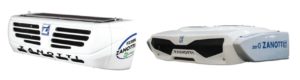
Компания «ZANOTTI S.p.A.» благодаря многолетнему опыту сегодня стала синонимом неоспоримого качества, надежности и безопасности в области производства холодильного оборудования для пищевой промышленности. Основная деятельность компании направлена на оптимизацию использования «холода» в процессе замораживания и хранения продукции агропродовольственного сектора, во время сушки и созревания колбасных изделий и сыров, при консервации зерновых холодом в силосных башнях и хладообеспечении рефрижераторного транспорта.
Инструкция по изменению параметров электронной панели управления типа ZANOTTI Electronic (CAREL IR32)
Инструкция по изменению параметров электронной панели управления DB»O»
Инструкция по изменению параметров электронной панели управления SB (для машин у которых сер.номер заканчивается на “I”)
Инструкция по изменению параметров электронной панели управления GM/GS
Описание работы POWERFROST EWPK 2000 ZANOTTI
Инструкция по изменению параметров электронной панели управления AS-AC-SB-TP SP»C»-SP»O»-DB»O»
Устройство программирующее циклы оттайки — Модель 13102/24
Системы управления и контроля уровня масла для холодильных систем и тепловых насосов (EN 378-1)
Монитор напряжения фирмы «EMIREL»
Инструкция по изменению параметров электронной панели управления регулятора CAREL32
Тел.: +7 (495) 410-96-90, многоканальный
E-mail: coldholod@bk.ru
Москва и московская область
Время работы: пн-вс 7:00-23:00
Прием заявок: круглосуточно
- Manuals
- Brands
- Zanotti Manuals
- Refrigerator
- DFZ
- Use and maintenance instructions
-
Contents
-
Table of Contents
-
Troubleshooting
-
Bookmarks
Quick Links
DFZ
DFZ
MANUALE USO E MANUTENZIONE
MANUALE USO E MANUTENZIONE
USE
AND MAINTENANCE INSTRUCTIONS
USE
AND MAINTENANCE INSTRUCTIONS
INSTRUCTIONS D’UTILISA
TION ET D’ENTRETIEN
INSTRUCTIONS D’UTILISA
TION ET D’ENTRETIEN
BEDIENUNGS- UND W
ARTUNGSANLEITUNG
BEDIENUNGS- UND W
ARTUNGSANLEITUNG
MANUAL
DE USO
Y
MANTENIMIENT
O
MANUAL
DE USO
Y
MANTENIMIENT
O
Related Manuals for Zanotti DFZ
Summary of Contents for Zanotti DFZ
-
Page 1
MANUALE USO E MANUTENZIONE MANUALE USO E MANUTENZIONE AND MAINTENANCE INSTRUCTIONS AND MAINTENANCE INSTRUCTIONS INSTRUCTIONS D’UTILISA TION ET D’ENTRETIEN INSTRUCTIONS D’UTILISA TION ET D’ENTRETIEN BEDIENUNGS- UND W ARTUNGSANLEITUNG BEDIENUNGS- UND W ARTUNGSANLEITUNG MANUAL DE USO MANTENIMIENT MANUAL DE USO MANTENIMIENT… -
Page 3
To carry out the instructions more easily, open the cover flap containing the key for the various functions… -
Page 4
ENGLISH… -
Page 5: Table Of Contents
TABLE OF CONTENTS pag. Preliminary information Important safety warnings Warranty How to order spare parts Disposing of the packing Disposing of the machine 1. Description of the machine 1.1 Available models 1.2 Main technical specifications 2. Rating plate 3. Description of the central control unit 3.1 Description of the display (keys) 4.
-
Page 6
Time and display contrast programming 4.8.1 Continuous operation 4.8.2 Disabling Diesel operation 4.8.3 Keyboard block 4.8.4 Print or record data Alarms 5. Goods loading procedure 5.1 Storage and stacking 5.2 Mobile partitions 5.3 Tips on the temperatures of carried goods 5.4 Recommendations on how to best use your refrigerator unit 6. -
Page 7: Preliminary Information
Preliminary information Thank you for choosing one of the models of DFZ ZANOTTI refrigeration units. This manual is addressed to the operators of DFZ ZANOTTI refrigeration units. Inside you will find the necessary information to use and service the products correctly, safety tips, warranty terms as well as suggestions on the best way of transporting your goods.
-
Page 8
Safety Tips By drilling the walls of the unit or the isothermal cold room, you could damage the electric wires or the refrigeration piping. Should such action be strictly nec- essary, great care should be taken to avoid any damage. Touching turning fans and moving belts can cause irreparable damage or injury. -
Page 9: Warranty
Engine The PERKINS engines fitted on all DFZ ZANOTTI refrigeration units are designed to keep pollution caused by exhaust gas at a minimum level. However, we strongly recommend to avoid starting the engine in a confined area, as the exhaust gas is toxic. The symptoms caused by carbon monoxide produced by fuel combustion are the following: –…
-
Page 10: How To Order Spare Parts
How to order spare parts When ordering spare parts, always include the serial number shown on the machine’s rating plate. Disposing of the packing Dispose of all wooden, plastic and polystyrene packing in compliance with the laws in force in the Country where the equipment is used. Disposing of the machine Should the machine be scrapped, its components must not be scattered in the environment.
-
Page 11: Description Of The Machine
1. Description of the machine The DFZ refrigeration units are made up of the following main components: 1. a condensing unit installed outside the isothermal box; 2. an evaporating unit installed inside the isothermal box; 3. an electronic central control unit located in the driver’s cab of the vehicle.
-
Page 12
DFZ 430 P. on road P. rmains Refrigeration power Amb. t. 30°C Cold room t. 0°C 6098W 4951W Amb. t. 30°C Cold room t. -20°C 3724W 3014W Road/mains compressor 170 cm Road engine Perkins 676 cm Condenser fan No. 1 helical-type belt-driven fan… -
Page 13
DFZ 465 P. on road P. rmains Refrigeration power Amb. t. 30°C Cold room t. 0°C 9500W 7848W Amb. t. 30°C Cold room t. -20°C 5400W 3555W Road/mains compressor 230 cm Road engine Perkins 954 cm Condenser fan No. 1 helical-type belt-driven fan… -
Page 14
DFZ 465U (Cubic Evaporator) P. on road P. rmains Refrigeration power Amb. t. 30°C Cold room t. 0°C 10908W 6090W Amb. t. 30°C Cold room t. -20°C 6636W 3868W Road/mains compressor 235 cm Road engine Perkins 957 cm Condenser fan No. -
Page 15
DFZ 465U (Flat Evaporator) P. on road P. rmains Refrigeration power Amb. t. 30°C Cold room t. 0°C 9739W 5561W Amb. t. 30°C Cold room t. -20°C 5630W 3098W Road/mains compressor 235 cm Road engine Perkins 954 cm Condenser fan No. -
Page 16: Rating Plate
2. Rating plate The DFZ ZANOTTI units are identified by plates located on the right side of the condensing circuit. They contain all the information to be communicated to the technicians in case of servicing, i.e.: – model – serial number –…
-
Page 17: Description Of The Central Control Unit
3. Description of the central control unit The DFZ ZANOTTI refrigeration units are equipped with a microprocessor-based electronic controller (driver’s cabin control) which manages operation in a fully automatic way. In particular, the electronic controller supervises the operations for turning the diesel engine and electric motor on and off depending on the set temperature.
-
Page 18: Operation
4. Operation 4.1 Before operating the unit 1. Check the belts. In fact, their tension must be perfect in order to prevent them from slipping if they are too slack (as this would generate heat and would therefore shorten the life of the belts) or the bearings from wearing out too fast if the belts are too tight.
-
Page 19: Setting The Unit At Work
4.2 Setting the unit at work Press push-button 1 to turn on the driver’s cabin control. The mask shown in f i g . 2 will appear after a few seconds. This mask shows: • TA1: Cold room temperature • SP1: operating set point •…
-
Page 20: Turning On The Refrigeration Unit
If two cold rooms are present, the mask will appear: To program the set point of the second cold room SP2, proceed as follows: — Press key : the cursor will start blinking under the present SP1 set point value. — Press the key until the value relating to SP2 is highlighted.
-
Page 21: Defrost
WARNING If the plug is connected before the diesel engine is stopped using the button ( f i g . 2 ), the diesel engine will turn off and the electric motor will come on after approximately 5 minutes. Similarly, if power is interrupted during electric standby, automatic startup of the diesel engine will take place after 5 minutes.
-
Page 22: Displaying The Temperature Chart
In this mask, you can see for how many hours the oil and oil filter have been used, as well as the total working hours of the diesel engine and electric motor. When the oil or oil filter have been used for over a limit number of hours, the sym- will be displayed on the main mask;…
-
Page 23
USER’S HANDBOOK UPDATE The cabin command has a slightly different graphic display and several new functions. The main window is as shown in the figure below: In this window three indications can be seen at the top left: which indicates the automatic function (start/stop); the snow-flake which indicates turning on of cold;… -
Page 24: Time And Display Contrast Programming
4.8 Time and display contrast programming Starting from the main mask and pressing key first and then key , you will access the mask below. By pressing key you can access the clock programming mask: press key to highlight the day, press the key to go from one term to another, press the UP/DOWN key to set the new value.
-
Page 25: Continuous Operation
4.8.1 Continuous operation This function allows the start/stop function of the Diesel motor to be cut-out and kept in motion in a continuous way; to activate this function starting from the main window press the key , the following window appears: then press the key , instead of will appear on the display indicating…
-
Page 26: Keyboard Block
4.8.3 Keyboard block To prevent unwanted interventions the keyboard blocking function has been introduced; activate it starting from the main window, press the key then the key , in this way the following window is accessed: now press the key , to go to the following window where entering the password will automatically bring up the following window which will be the only one that can be displayed and the on/off key will be the…
-
Page 27: Print Or Record Data
To unblock the keyboard press the MENU key and re-enter the password in the following window 4.8.4 Print or record data In the following window, reached by pressing and the key starting from the main window is the key which when pressed accesses the window where the following con be entered: From: the data printing start date To: the end of printing date…
-
Page 28
Example: From: 10/04/01 To: 12/04/01 Evp: 1 Res: 10 min Sta: 12:00 (noon) Sto. 14:00 (2 p.m.) Prn: PRINTER With the data thus entered press the key to print all the data from 10/04/01 to 12/04/01 recorded from 12 noon to 2 p.m. every 10 minutes. Whenever using download on PC, the Hyperterminal present in the windows accessories must be accessed. -
Page 29: Alarms
4.9 Alarms Every time an alarm occurs, the icon starts blinking and the buzzer goes off. To silence the buzzer, just press any key. To see the alarm mask, press key ; in this way, you will access the mask below where you will see the different alarm codes.
-
Page 30: Gb Gb
Alarm code Description Type Water temperature alarm Automatic reset Oil pressure alarm Manual reset Thermal relay alarm Manual reset Pressure switch alarm Automatic reset Low battery level alarm Automatic reset Damaged room sensor alarm Manual reset Damaged defrost sensor alarm Warning only Starting failure/damaged alternator Manual reset…
-
Page 31
A04 Pressure switch alarm This alarm occurs when either the high or low pressure switch trips. The high pressure switch may trip due to poor cleaning of the condenser or loosened con- denser fan belts. The low pressure switch may trip due to refrigerant leaks. By tripping it causes the machine to stop until the alarm itself disappears. -
Page 32
A11 Oil level alarm (optional) It is a warning alarm which has no consequences on the operation of the machine. A12 Air filter alarm This alarm occurs if the air filter cartridge is clogged. Replace the cartridge. It is a warning alarm which has no consequences on the operation of the machine. A13 Oil filter alarm (optional) It is a warning alarm which has no consequences on the operation of the machine. -
Page 33: Goods Loading Procedure
Avoid positioning the goods leaning on the cold room walls. In fact, the walls fil- ter heat from the environment, which is most damaging to this type of goods. The DFZ ZANOTTI refrigeration units are designed to keep the goods at their loading temperature.
-
Page 34: Tips On The Temperatures Of Carried Goods
• 0/15 cm (4/6 in) is the minimum clearance between the cargo and the walls of the cold room. • When parking, leave your vehicle in the shade and make sure that the DFZ ZANOTTI refrigeration unit does not remain idle for a long time.
-
Page 35: Using The Unit Safely
6. Using the unit safely The DFZ ZANOTTI units are built to keep the operators safe. The use of protec- tion gloves is, in any case, fundamentally important during controls, repairs, and maintenance for every action which the operator must carry out inside the unit,…
-
Page 36: Routine Maintenance
7. Routine maintenance MAINTENANCE INTERVALS 50 hours 1000 hours Action or 15 days or 10 months • Check the concentration of coolant • Check the trapezoidal belts for tension and wear • Check and adjust the engine RPM • Check that all screws and nuts are well tightened •…
-
Page 37
Important • Carry out the following maintenance operations after one year: — renovating refrigerant, — checking and adjusting valve clearances, — checking that the cylinder heads are well tightened, — checking that the injectors are in good working condition. BELTS Properly tensioned belts allow a good transmission and wear out less. -
Page 38: Troubleshooting Guide
• The isothermal cold room might be damaged or have leaks. Should you find any other faults, check the alarm pages on the keyboard locat- ed on the vehicle’s dashboard. In case of further problems, contact the nearest ZANOTTI dealer.
-
Page 39: A.t.p. Europe» Regulation
9. Abstract of the “A.T.P. Europe” regulation (march 1974) Authorization for vehicles used to carry perishable foodstuffs. Prior to the begin- ning of its operation, the refrigerated vehicle must be authorized by the Departmental Veterinary Service. CHARACTERISTICS OF VEHICLES USED TO CARRY PERISHABLE FOOD- STUFFS REFRIGERATED VEHICLE.
-
Page 40
SYMBOLS, ITEMS AND IDENTIFICATION PLATES TO BE AFFIXED ON REFRIGERATED VEHICLES. Refrigeration plate: this wording must be followed by the identification items according to the following list: • Class A standard refrigerated vehicle • Class A reinforced refrigerated vehicle • Class B reinforced refrigerated vehicle •… -
Page 41: Wiring Diagram Key
Wiring diagram key Alternator Diesel fuel pump relay Room sensor Oil pressure switch relay Radiator sensor KPR-1-2 Crankcase heating relay Glow plugs Timer for cooling fan delay Heaters on condensate Phase sequencer drain pipes KYAV High speed solenoid valve relay Automatic switch Defrost solenoid valve relay Electronic control unit…
-
Page 42
Timbro officina autorizzata ZANOTTI Date — Date — Datum — Fecha Seal of the ZANOTTI authorized repair shop — Tampon du centre agréé ZANOTTI Stempel der autorisierten ZANOTTI-Werkstatt — Sello del taller autorizado ZANOTTI Ore funzionamento Hours of operation — Heures de fonctionnement — Betriebsstunden — Horas de funcionamiento N. -
Page 43
Timbro officina autorizzata ZANOTTI Date — Date — Datum — Fecha Seal of the ZANOTTI authorized repair shop — Tampon du centre agréé ZANOTTI Stempel der autorisierten ZANOTTI-Werkstatt — Sello del taller autorizado ZANOTTI Ore funzionamento Hours of operation — Heures de fonctionnement — Betriebsstunden — Horas de funcionamiento N. -
Page 44
ZANOTTI S.p.A. — 46020 PEGOGNAGA (Mantova) — Italy Via Martin L. King, n 30 — Tel. (0376) 5551- Telefax (0376) 536554 E-mail: info@zanotti.com — Internet: http://www.zanotti.com…
-
Инструкция на моноблоки Zanotti серии GM
Вложения:
константерм нравится это.
-
Инструкция на моноблоки Zanotti серии AS UNIBLOCK
Вложения:
-
C_AS.pdf
- Размер файла:
- 177,4 КБ
- Просмотров:
- 657
-
-
Инструкция на моноблоки Zanotti серии BX UNIBLOCK
Вложения:
-
C_BX.pdf
- Размер файла:
- 361,2 КБ
- Просмотров:
- 399
-
-
Инструкция на моноблоки Zanotti серии RS UNIBLOCK
Вложения:
-
C_RS.pdf
- Размер файла:
- 609,3 КБ
- Просмотров:
- 274
-
-
Инструкция на моноблоки Zanotti серии SB UNIBLOCK
Вложения:
-
C_SB.pdf
- Размер файла:
- 704,7 КБ
- Просмотров:
- 342
-
-
Инструкция на электронные панели управления Zanotti AS-AC-SB-TP
Вложения:
-
Инструкция на электронные панели управления IWP750LX Zanotti GM-GS-AS-TP
Вложения:
-
Инструкция на электронные панели управления CAREL IR32 Zanotti AZ-SZ
Вложения:
-
Инструкция на электронные панели управления Zanotti SB new
Вложения:
-
Инструкция на электронные панели управления POWERFROST EWPK 2000 Zanotti
Вложения:
-
компрессора установленные в Zanotti MGM-BGM
Вложения:
константерм нравится это.
-
электрические схемы Zanotti SB-GM-AS-GS-SPO-DBO-DBS-CUO-CUS-RCV-RDV
Вложения:
константерм нравится это.
-
таймер оттайки модель 13102/24 для Zanotti
Вложения:
-
Привет всем, помогите пожалуйста со средне температурной сплит системой zanotti mgs212112g. Проблема с температурой зависает на 12 градусах и гонит до минус 25
Поделиться этой страницей
- Manuals
- Brands
- Zanotti Manuals