
Quick Start Guide
www.zyxel.com
GS1920 Series
Intelligent Layer 2 GbE Switch
Version 4.10
Edition 3, 05/2014
Copyright © 2014 ZyXEL Communications Corporation
User’s Guide
Default Login Details
LAN IP Address
http://192.168.1.1
User Name
admin
Password
1234
-
Инструкции по эксплуатации
1

ZyXEL GS1920-24HP инструкция по эксплуатации
(381 страница)
- Языки:Английский
-
Тип:
PDF -
Размер:
10.35 MB -
Описание:
Интеллектуальный коммутатор Gigabit Ethernet с 24 разъемами RJ-45 и 4 SFP-слотами совмещенными с разъемами RJ-45
Просмотр
На NoDevice можно скачать инструкцию по эксплуатации для ZyXEL GS1920-24HP. Руководство пользователя необходимо для ознакомления с правилами установки и эксплуатации ZyXEL GS1920-24HP. Инструкции по использованию помогут правильно настроить ZyXEL GS1920-24HP, исправить ошибки и выявить неполадки.
-
Contents
-
Table of Contents
-
Troubleshooting
-
Bookmarks
Quick Links
GS1920 Series
Intelligent Layer 2 GbE Switch
Version 4.30
Edition 1, 10/2015
Quick Start Guide
User’s Guide
Default Login Details
LAN IP Address
User Name
Password
www.zyxel.com
http://192.168.1.1
admin
1234
Copyright © 2015 ZyXEL Communications Corporation
Related Manuals for ZyXEL Communications GS1920 Series
Summary of Contents for ZyXEL Communications GS1920 Series
-
Page 1
GS1920 Series Intelligent Layer 2 GbE Switch Version 4.30 Edition 1, 10/2015 Quick Start Guide User’s Guide Default Login Details LAN IP Address http://192.168.1.1 User Name admin Password 1234 www.zyxel.com Copyright © 2015 ZyXEL Communications Corporation… -
Page 2
Related Documentation • Web Configurator Online Help Click the help icon in any screen for help in configuring that screen and supplementary information. • More Information Go to support.zyxel.com to find other information on the Switch. GS1920 Series User’s Guide… -
Page 3: Table Of Contents
AAA ………………………….209 IP Source Guard ………………………220 Loop Guard ……………………….245 Layer 2 Protocol Tunneling ……………………249 PPPoE …………………………253 Error Disable ……………………….261 Private VLAN ……………………….268 Green Ethernet ……………………….270 Link Layer Discovery Protocol (LLDP) ………………..272 Static Route ……………………….297 Differentiated Services ……………………..300 GS1920 Series User’s Guide…
-
Page 4
ARP Setup ……………………….316 Maintenance ……………………….320 Access Control ……………………….329 Diagnostic ………………………..347 System Log ……………………….350 Syslog Setup ……………………….351 Cluster Management ……………………..354 MAC Table ………………………..360 ARP Table ………………………..363 Path MTU Table ……………………….365 Configure Clone ……………………….366 IPv6 Neighbor Table ……………………..369 Troubleshooting ……………………….371 GS1920 Series User’s Guide… -
Page 5: Table Of Contents
3.1.1 Gigabit Ethernet Ports ………………….26 3.1.2 Mini-GBIC Slots ……………………27 3.1.3 LED Mode (only available for GS1920-48HP) ……………..29 3.2 Rear Panel ……………………….29 3.2.1 Power Connector ……………………29 3.3 LEDs ………………………….30 3.4 Reset to Factory Defaults ……………………30 3.4.1 Side Panels ……………………..31 GS1920 Series User’s Guide…
-
Page 6
Status and ZON ………………………53 7.1 Overview ……………………….53 7.1.1 What You Can Do ……………………53 7.2 Status …………………………53 7.3 ZyXEL One Network (ZON) Utility Screen ………………55 7.4 ZON Neighbor Management Screen ………………..56 7.5 Port Status ……………………….57 7.5.1 Port Details ………………………59 GS1920 Series User’s Guide… -
Page 7
9.5 Configure VLAN Port Settings ………………….98 9.6 Subnet Based VLANs ……………………99 9.6.1 Configuring Subnet Based VLAN ………………100 9.7 Protocol Based VLANs ……………………102 9.7.1 Configuring Protocol Based VLAN ………………102 9.8 Voice VLAN ………………………..104 9.9 MAC Based VLAN ………………………105 GS1920 Series User’s Guide… -
Page 8
13.8.1 MSTP Port Configuration ………………..133 13.9 Multiple Spanning Tree Protocol Status ………………135 13.10 Technical Reference ……………………137 13.10.1 MSTP Network Example ………………..137 13.10.2 MST Region ……………………138 13.10.3 MST Instance ……………………139 13.10.4 Common and Internal Spanning Tree (CIST) …………..139 GS1920 Series User’s Guide… -
Page 9
18.1.2 What You Need to Know ………………….155 18.1.3 MAC Authentication ………………….156 18.2 Port Authentication Configuration ………………..157 18.3 Activate IEEE 802.1x Security ………………..157 18.3.1 Guest VLAN ……………………158 18.4 Activate MAC Authentication ………………….160 Chapter 19 Port Security ………………………..163 19.1 Port Security Overview …………………….163 GS1920 Series User’s Guide… -
Page 10
Multicast ……………………….184 24.1 Multicast Overview ……………………184 24.1.1 What You Can Do ……………………184 24.1.2 What You Need to Know ………………….184 24.2 Multicast Setup ……………………..188 24.3 IPv4 Multicast Status ……………………188 24.3.1 IGMP Snooping ……………………189 24.3.2 IGMP Snooping VLAN ………………….191 GS1920 Series User’s Guide… -
Page 11
26.6.2 DHCP Snooping VLAN Configure ………………231 26.6.3 DHCP Snooping VLAN Port Configure …………….232 26.7 ARP Inspection Status …………………….233 26.8 ARP Inspection VLAN Status ………………….234 26.9 ARP Inspection Log Status ………………….235 26.10 ARP Inspection Configure ………………….237 26.10.1 ARP Inspection Port Configure ………………238 GS1920 Series User’s Guide… -
Page 12
30.1.2 Error-Disable Recovery Overview ………………261 30.1.3 What You Can Do ……………………261 30.2 Error Disable Screen ……………………262 30.3 Error-Disable Status ……………………262 30.4 CPU Protection Configuration ………………….264 30.5 Error-Disable Detect Configuration ………………..266 30.6 Error-Disable Recovery Configuration ………………266 Chapter 31 Private VLAN ………………………..268 GS1920 Series User’s Guide… -
Page 13
35.1 Differentiated Services Overview ………………..300 35.1.1 What You Can Do ……………………300 35.1.2 What You Need to Know ………………….300 35.2 Activating DiffServ ……………………301 35.3 DSCP-to-IEEE 802.1p Priority Settings ………………302 35.3.1 Configuring DSCP Settings ………………..303 Chapter 36 DHCP…………………………304 36.1 DHCP Overview ……………………..304 GS1920 Series User’s Guide… -
Page 14
38.6 Tech-Support ……………………..325 38.7 Technical Reference ……………………326 38.7.1 FTP Command Line ………………….326 38.7.2 Filename Conventions ………………….327 38.7.3 FTP Command Line Procedure ………………327 38.7.4 GUI-based FTP Clients ………………….328 38.7.5 FTP Restrictions …………………….328 Chapter 39 Access Control ……………………..329 GS1920 Series User’s Guide… -
Page 15
43.2 Cluster Management Status ………………….355 43.3 Clustering Management Configuration ………………356 43.4 Technical Reference ……………………358 43.4.1 Cluster Member Switch Management …………….358 Chapter 44 MAC Table ……………………….360 44.1 MAC Table Overview ……………………360 44.1.1 What You Can Do ……………………360 GS1920 Series User’s Guide… -
Page 16
49.1 Power, Hardware Connections, and LEDs ………………371 49.2 Switch Access and Login ………………….372 49.3 Switch Configuration ……………………374 Appendix A Customer Support ………………….375 Appendix B Common Services ………………….381 Appendix C IPv6 ……………………..384 Appendix D Legal Information ………………….392 Index …………………………397 GS1920 Series User’s Guide… -
Page 17: User’s Guide
User’s Guide…
-
Page 18: Getting To Know Your Switch
H A PT ER Getting to Know Your Switch 1.1 Introduction This chapter introduces the main features and applications of the Switch. The GS1920 Series consist of the four following models: • GS1920-24 • GS1920-24HP • GS1920-48 • GS1920-48HP Referring to PoE model(s) in this User’s Guide only applies for GS1920-24HP and GS1920-48HP.
-
Page 19: Backbone Application
Switch. You can provide a super-fast uplink connection by using a Gigabit Ethernet/mini-GBIC port on the Switch. Moreover, the Switch eases supervision and maintenance by allowing network managers to centralize multiple servers at a single location. GS1920 Series User’s Guide…
-
Page 20: High Performance Switching Example
With VLAN, a station cannot directly talk to or hear from stations that are not in the same group(s) unless such traffic first goes through a router. For more information on VLANs, refer to Chapter 9 on page GS1920 Series User’s Guide…
-
Page 21: Ways To Manage The Switch
• Change the password. Use a password that’s not easy to guess and that consists of different types of characters, such as numbers and letters. • Write down the password and put it in a safe place. GS1920 Series User’s Guide…
-
Page 22
Switch to its factory default settings. If you backed up an earlier configuration file, you would not have to totally re-configure the Switch. You could simply restore your last configuration. See Section 3.4 on page 30 for how to reset the Switch. GS1920 Series User’s Guide… -
Page 23: Hardware Installation And Connection
• Four M5 flat head screws and a #2 Philips screwdriver. Failure to use the proper screws may damage the unit. 2.3.1.1 Precautions • Make sure the rack will safely support the combined weight of all the equipment it contains. GS1920 Series User’s Guide…
-
Page 24: Attaching The Mounting Brackets To The Switch
Position a mounting bracket (that is already attached to the Switch) on one side of the rack, lining up the two screw holes on the bracket with the screw holes on the side of the rack. GS1920 Series User’s Guide…
-
Page 25
Figure 6 Mounting the Switch on a Rack Using a #2 Philips screwdriver, install the M5 flat head screws through the mounting bracket holes into the rack. Repeat steps to attach the second mounting bracket on the other side of the rack. GS1920 Series User’s Guide… -
Page 26: Hardware Panels
An auto-negotiating port can detect and adjust to the optimum Ethernet speed (10/100/1000 Mbps) and duplex mode (full duplex or half duplex) of the connected device. An auto-crossover (auto-MDI/MDI-X) port automatically works with a straight-through or crossover Ethernet cable. GS1920 Series User’s Guide…
-
Page 27: Mini-Gbic Slots
To avoid possible eye injury, do not look into an operating fiber-optic module’s connectors. • Type: SFP connection interface • Connection speed: 1 Gigabit per second (Gbps) 3.1.2.1 Transceiver Installation Use the following steps to install a mini-GBIC transceiver (SFP module). GS1920 Series User’s Guide…
-
Page 28
Remove the fiber optic cables from the transceiver. Open the transceiver’s latch (latch styles vary). Pull the transceiver out of the slot. Figure 13 Removing the Fiber Optic Cables Figure 14 Opening the Transceiver’s Latch Example GS1920 Series User’s Guide… -
Page 29: Led Mode (Only Available For Gs1920-48Hp)
To connect power to the Switch, insert the female end of the power cord to the AC power receptacle on the rear panel. Connect the other end of the supplied power cord to a power outlet. Make sure that no objects obstruct the airflow of the fans (located on the side of the unit). GS1920 Series User’s Guide…
-
Page 30: Leds
This means that you will lose all configurations that you had previously and the default Switch IP address, user name and password will be reset to 192.168.1.1, admin and 1234 respectively. GS1920 Series User’s Guide…
-
Page 31: Side Panels
IP address of your computer to be in the same subnet as that of the default Switch IP address (192.168.1.1). 3.4.1 Side Panels The reset button is located at the side of the Switch as shown. Figure 20 Side Panel: GS1920-48 Figure 21 Side Panel: GS1920-24, GS1920-24HP, GS1920-48HP GS1920 Series User’s Guide…
-
Page 32: Technical Reference
Technical Reference…
-
Page 33: The Web Configurator
The login screen appears. The default username is admin and associated default password is 1234. The date and time display as shown if you have not configured a time server nor manually entered a time and date in the General Setup screen. GS1920 Series User’s Guide…
-
Page 34: The Status Screen
The following figure shows the navigating components of a web configurator screen. Figure 23 Web Configurator Home Screen for PoE model(s) (Status) A — Click the menu items to open submenu links, and then click on a submenu link to open the screen in the main window. GS1920 Series User’s Guide…
-
Page 35
G — Click this link to go to the ZON Neighbor Management screen where you can see and manage neighbor devices learned by the Switch. In the navigation panel, click a main link to reveal a list of submenu links. Table 4 Navigation Panel Sub-links Overview BASIC SETTING ADVANCED APPLICATION IP APPLICATION MANAGEMENT GS1920 Series User’s Guide… -
Page 36
This link takes you to screens where you can configure the Switch to group packets based on the specified criteria. Policy Rule This link takes you to a screen where you can configure the Switch to perform special treatment on the grouped packets. GS1920 Series User’s Guide… -
Page 37
This link takes you to a screen where you can view the MAC addresses – IP address resolution table. Path MTU Table This link takes you to a screen where you can view the path MTU aging time, index, destination address, MTU, and expire settings. GS1920 Series User’s Guide… -
Page 38: Change Your Password
Click the Save link in the upper right hand corner of the web configurator to save your configuration to nonvolatile memory. Nonvolatile memory refers to the Switch’s storage that remains even if the Switch’s power is turned off. Note: Use the Save link when you are done with a configuration session. GS1920 Series User’s Guide…
-
Page 39: Switch Lockout
When you see the message “Press any key to enter Debug Mode within 3 seconds…” press any key to enter debug mode. Type atlc after the “Enter Debug Mode” message. Wait for the “Starting XMODEM upload” message before activating XMODEM upload on your terminal. GS1920 Series User’s Guide…
-
Page 40: Logging Out Of The Web Configurator
Figure 25 Web Configurator: Logout Screen 4.8 Help The web configurator’s online help has descriptions of individual screens and some supplementary information. Click the Help link from a web configurator screen to view an online help description of that screen. GS1920 Series User’s Guide…
-
Page 41: Initial Setup Example
In this example, you want to configure port 1 as a member of VLAN 2. Figure 26 Initial Setup Network Example: VLAN Click Advanced Application > VLAN > VLAN Configuration in the navigation panel and click the Static VLAN Setup link. GS1920 Series User’s Guide…
-
Page 42: Setting Port Vid
VLAN group that the tag defines. In the example network, configure 2 as the port VID on port 1 so that any untagged frames received on that port get sent to VLAN 2. GS1920 Series User’s Guide…
-
Page 43: Configuring Switch Management Ip Address
The default management IP address of the Switch is 192.168.1.1. You can configure another IP address in a different subnet for management purposes. The following figure shows an example. Figure 28 Initial Setup Example: Management IP Address GS1920 Series User’s Guide…
-
Page 44
This is the same as the VLAN ID you configure in the Static VLAN screen. Click Add to save your changes back to the run- time memory. Settings in the run-time memory are lost when the Switch’s power is turned off. GS1920 Series User’s Guide… -
Page 45: Tutorials
1 and 100 DHCP Client (B) 1 and 100 DHCP Client (C) 1 and 100 Access the Switch through http://192.168.1.1 by default. Log into the Switch by entering the username (default: admin) and password (default: 1234). GS1920 Series User’s Guide…
-
Page 46
Go to Advanced Application > VLAN > VLAN Configuration > VLAN Port Setup, and set the PVID of the ports 5, 6 and 7 to 100. This tags untagged incoming frames on ports 5, 6 and 7 with the tag 100. Figure 31 Tutorial: Tag Untagged Frames GS1920 Series User’s Guide… -
Page 47
5 because the DHCP server is connected to port 5. Keep ports 6 and 7 Untrusted because they are connected to DHCP clients. Click Apply. Tutorial: Set the DHCP Server Port to Trusted Figure 33 GS1920 Series User’s Guide… -
Page 48: How To Use Dhcpv4 Relay On The Switch
In this example, you have configured your DHCP server (192.168.2.3) and want to have it assign a specific IP address (say 172.16.1.18) to DHCP client A based on the system name, VLAN ID and port number in the DHCP request. Client A connects to the Switch’s port 2 in VLAN 102. GS1920 Series User’s Guide…
-
Page 49: Creating A Vlan
Click Advanced Application > VLAN > VLAN Configuration > Static VLAN Setup. In the Static VLAN screen, select ACTIVE, enter a descriptive name (VLAN 102 for example) in the Name field and enter 102 in the VLAN Group ID field. GS1920 Series User’s Guide…
-
Page 50
Enter 102 in the PVID field for port 2 to add a tag to incoming untagged frames received on that port so that the frames are forwarded to the VLAN group that the tag defines. 10 Click Apply to save your changes back to the run-time memory. GS1920 Series User’s Guide… -
Page 51: Configuring Dhcpv4 Relay
Enter the DHCP server’s IP address (192.168.2.3 in this example) in the Remote DHCP Server 1 field. Select default1 or default2 in the Option 82 Profile field. Click Apply to save your changes back to the run-time memory. GS1920 Series User’s Guide…
-
Page 52: Troubleshooting
You configured the correct VLAN ID, port number and system name for DHCP relay on both the DHCP server and the Switch. You clicked the Save link on the Switch to have your settings take effect. GS1920 Series User’s Guide…
-
Page 53: Status And Zon
7.2 Status The Status screen displays when you log into the Switch or click Status at the top right corner of the web configurator. The Status screen displays general device information, system status, and its IP addresses. GS1920 Series User’s Guide…
-
Page 54
After it times out you have to log in with your password again. Detail Click this link to go to the Basic Setting > System Info screen to check other detailed information, such as system resource usage and the Switch temperature, fan speeds or voltage. GS1920 Series User’s Guide… -
Page 55: Zyxel One Network (Zon) Utility Screen
ZON Utility screen and you can perform tasks like basic configuration of the devices and batch firmware upgrade in it. You can download the ZON Utility at www.zyxel.com and install it on a PC. The following figure shows the ZON Utility screen. GS1920 Series User’s Guide…
-
Page 56: Zon Neighbor Management Screen
(turn the power off and then back on again), and reset to factory default settings in the Neighbor Management screen. For more information on LLDP, see (Section 33.1 on page 272). Click Status > Neighbor to see the following screen. Status > Neighbor Figure 44 GS1920 Series User’s Guide…
-
Page 57: Port Status
7.5 Port Status This screen displays a port statistical summary with links to each port showing statistical details. To view the port statistics, click Status in all web configurator screens and then the Port Status link GS1920 Series User’s Guide…
-
Page 58
This field shows the number of received frames on this port. Errors This field shows the number of received errors on this port. Tx KB/s This field shows the number of kilobytes per second transmitted on this port. GS1920 Series User’s Guide… -
Page 59: Port Details
Click a number in the Port column in the Port Status screen to display individual port statistics. Use this screen to check status and detailed performance data about an individual port on the Switch. Figure 46 Port Status > Port Details GS1920 Series User’s Guide…
-
Page 60
This is the number of times a late collision is detected, that is, after 512 bits of the packets have already been transmitted. Error Packet The following fields display detailed information about packets received that were in error. RX CRC This field shows the number of packets received with CRC (Cyclic Redundant Check) error(s). GS1920 Series User’s Guide… -
Page 61
1024 and 1518 octets in length. Giant This field shows the number of packets (including bad packets) received that were between 1519 octets and the maximum frame size. The maximum frame size varies depending on your switch model. GS1920 Series User’s Guide… -
Page 62: Basic Setting
90) to configure the default domain name server. 8.2 System Information In the navigation panel, click Basic Setting > System Info to display the screen as shown. Use this screen to view general system information. You can check the firmware version number. GS1920 Series User’s Guide…
-
Page 63
You may choose the temperature unit (Centigrade or Fahrenheit) in this field. Temperature BOARD, MAC and PHY refer to the location of the temperature sensors on the Switch printed circuit board. Current This shows the current temperature at this sensor. GS1920 Series User’s Guide… -
Page 64: General Setup
Error is displayed. 8.3 General Setup Use this screen to configure general settings such as the system name and time. Click Basic Setting > General Setup in the navigation panel to display the screen as shown. GS1920 Series User’s Guide…
-
Page 65
This field displays the date you open this menu. New Date (yyyy- Enter the new date in year, month and day format. The new date then appears in the mm-dd) Current Date field after you click Apply. GS1920 Series User’s Guide… -
Page 66: Introduction To Vlans
In traditional switched environments, all broadcast packets go to each and every individual port. With VLAN, all broadcasts are confined to a specific broadcast domain. Note: VLAN is unidirectional; it only governs outgoing traffic. GS1920 Series User’s Guide…
-
Page 67: Switch Setup
GARP Timer: Switches join VLANs by making a declaration. A declaration is made by issuing a Join message using GARP. Declarations are withdrawn by issuing a Leave message. A Leave All message terminates all registrations. GARP timers set declaration timeout values. See the chapter on VLAN setup for more background information. GS1920 Series User’s Guide…
-
Page 68: Ip Setup
8.6 IP Setup Use the IP Setup screen to configure the Switch IP address, default gateway device, and the management VLAN ID. The default gateway specifies the IP address of the default gateway (next hop) for outgoing traffic. GS1920 Series User’s Guide…
-
Page 69: Management Ip Addresses
Select this option if you don’t have a DHCP server or if you wish to assign static IP address information to the Switch. You need to fill in the following fields when you select this option. GS1920 Series User’s Guide…
-
Page 70: Port Setup
Click Cancel to clear the selected check boxes in the Delete column. 8.7 Port Setup Use this screen to configure Switch port settings. Click Basic Setting > Port Setup in the navigation panel to display the configuration screen. GS1920 Series User’s Guide…
-
Page 71
Enter a descriptive name that identifies this port. You can enter up to 64 alpha-numerical characters. Note: Due to space limitation, the port name may be truncated in some web configurator screens. Type This field displays the capacity that the port can support. GS1920 Series User’s Guide… -
Page 72: Poe Status
In the figure below, the IP camera and IP phone get their power directly from the Switch. Aside from minimizing the need for cables and wires, PoE removes the hassle of trying to find a nearby electric outlet to power up devices. GS1920 Series User’s Guide…
-
Page 73
Note: The POE (Power over Ethernet) devices that supply or receive power and their connected Ethernet cables must all be completely indoors. To view the current amount of power that PDs are receiving from the Switch, click Basic Setting > PoE Setup. Figure 53 Basic Setting > PoE Status GS1920 Series User’s Guide… -
Page 74: Poe Time Range Status
This field displays the maximum amount of power the PD could use from the Switch on this (mW) port. 8.8.1 PoE Time Range Status Use this screen to see whether PoE is scheduled to be enabled on a port. GS1920 Series User’s Guide…
-
Page 75: Poe Setup
Use this screen to set the priority levels, power-up mode and schedule for the Switch in distributing power to PDs. Click the PoE Setup link in the Basic Setting > PoE Status screen. The following screen opens. GS1920 Series User’s Guide…
-
Page 76
Note: Changes in this row are copied to all the ports as soon as you make them. Select this to provide power to a PD connected to the port. If left unchecked, the PD connected to the port cannot receive power from the Switch. GS1920 Series User’s Guide… -
Page 77: Interface Setup
Use this screen to set IPv6 interfaces on which you can configure an IPv6 address to access and manage the Switch. Click Basic Setting > Interface Setup in the navigation panel to display the configuration screen. GS1920 Series User’s Guide…
-
Page 78: Ipv6
Click Cancel to clear the check boxes. 8.10 IPv6 Use this screen to view the IPv6 interface status and configure Switch’s management IPv6 addresses. Click Basic Setting > IPv6 in the navigation panel to display the IPv6 status screen as shown next. GS1920 Series User’s Guide…
-
Page 79: Ipv6 Interface Status
This field displays whether the IPv6 interface is activated or not. 8.10.1 IPv6 Interface Status Use this screen to view a specific IPv6 interface status and detailed information. Click an interface index number in the Basic Setting > IPv6 screen. The following screen opens. GS1920 Series User’s Guide…
-
Page 80
This field displays the Switch’s link-local IP address and prefix generated by the interface. It Address also shows whether the IP address is preferred, which means it is a valid address and can be used as a sender or receiver address. GS1920 Series User’s Guide… -
Page 81
This field displays the address record when the Switch queries the DNS server to resolve domain names. Restart Click Click Here to send a new DHCP request to the DHCPv6 server and update the IPv6 DHCPv6 Client address and DNS information for this interface. GS1920 Series User’s Guide… -
Page 82: Ipv6 Configuration
Click the link to go to a screen where you can configure the Switch DHCP settings. Setup 8.10.3 IPv6 Global Setup Use this screen to configure the global IPv6 settings. Click the link next to IPv6 Global Setup in the IPv6 Configuration screen to display the screen as shown next. GS1920 Series User’s Guide…
-
Page 83: Ipv6 Interface Setup
Use this screen to turn on or off an IPv6 interface and enable stateless autoconfiguration on it. Click the link next to IPv6 Interface Setup in the IPv6 Configuration screen to display the screen as shown next. Figure 61 Basic Setting > IPv6 > IPv6 Configuration > IPv6 Interface Setup GS1920 Series User’s Guide…
-
Page 84: Ipv6 Link-Local Address Setup
Table 25 Basic Setting > IPv6 > IPv6 Configuration > IPv6 Link-Local Address Setup LABEL DESCRIPTION Interface Select the IPv6 interface you want to configure. Link-Local Manually configure a static IPv6 link-local address for the interface. Address GS1920 Series User’s Guide…
-
Page 85: Ipv6 Global Address Setup
Save link on the top navigation panel to save your changes to the nonvolatile memory when you are done configuring. Cancel Click Cancel to begin configuring this screen afresh. GS1920 Series User’s Guide…
-
Page 86: Ipv6 Neighbor Discovery Setup
Specify the number of consecutive neighbor solicitations (from 0 to 600) the Switch sends for this interface. Enter 0 to turn off DAD. NS Interval Specify the time interval (from 1000 to 3600000 milliseconds) at which neighbor solicitations are re-sent for this interface. GS1920 Series User’s Guide…
-
Page 87: Ipv6 Neighbor Setup
Click the link next to IPv6 Neighbor Setup in the IPv6 Configuration screen to display the screen as shown next. Figure 65 Basic Setting > IPv6 > IPv6 Configuration > IPv6 Neighbor Setup GS1920 Series User’s Guide…
-
Page 88: Dhcpv6 Client Setup
Use this screen to configure the Switch’s DHCP settings when it is acting as a DHCPv6 client. Click the link next to DHCPv6 Client Setup in the IPv6 Configuration screen to display the screen as shown next. GS1920 Series User’s Guide…
-
Page 89
This field displays whether the Switch obtains a list of domain names from the DHCP server. Information This field displays the time interval (in seconds) at which the Switch exchanges other Refresh configuration information with a DHCPv6 server again. Minimum GS1920 Series User’s Guide… -
Page 90: Dns
This field displays priority of the DNS server address. Server Address This field displays the IP address of the DNS server. Source This field displays whether the DNS server address is configured manually (Static) or obtained automatically using DHCP/DHCPv6 (Dynamic). GS1920 Series User’s Guide…
-
Page 91: Vlan
VLAN and provides the information that switches need to process the frame across the network. A tagged frame is four bytes longer than an untagged frame and contains two bytes of TPID (Tag Protocol Identifier, residing within the type/length field of the Ethernet frame) GS1920 Series User’s Guide…
-
Page 92: Forwarding Tagged And Untagged Frames
GVRP (GARP VLAN Registration Protocol) is a registration protocol that defines a way for switches to register necessary VLAN members on ports across the network. Enable this function to permit VLAN groups beyond the local Switch. GS1920 Series User’s Guide…
-
Page 93: Port Vlan Trunking
1 and 2 (VLAN groups that are unknown to those switches) to pass through their VLAN trunking port(s). Figure 68 Port VLAN Trunking 9.1.2.3 Select the VLAN Type Select a VLAN type in the Basic Setting > Switch Setup screen. GS1920 Series User’s Guide…
-
Page 94: Vlan Status
This is the number of VLANs that match the searching criteria and display in the list below. Search Results This field displays only when you use the Search button to look for certain VLANs. Index This is the VLAN index number. Click on an index number to view more VLAN details. GS1920 Series User’s Guide…
-
Page 95: Vlan Details
This field shows how this VLAN was added to the Switch. Dynamic: using GVRP Static: added as a permanent entry Voice: manually added as a Voice VLAN MVR: added via multicast VLAN registration MAC-based: manually added as MAC-based VLAN GS1920 Series User’s Guide…
-
Page 96: Vlan Configuration
Click Click Here to configure the MAC Based VLAN for the Switch. 9.4 Configure a Static VLAN Use this screen to configure a static VLAN for the Switch. Click the Static VLAN Setup link in the VLAN Configuration screen to display the screen as shown next. GS1920 Series User’s Guide…
-
Page 97
Select Fixed for the port to be a permanent member of this VLAN group. Select Forbidden if you want to prohibit the port from joining this VLAN group. Tagging Select TX Tagging if you want the port to tag all outgoing frames transmitted with this VLAN Group ID. GS1920 Series User’s Guide… -
Page 98: Configure Vlan Port Settings
Use the VLAN Port Setup screen to configure the static VLAN (IEEE 802.1Q) settings on a port. Click the VLAN Port Setup link in the VLAN Configuration screen. Figure 74 Advanced Application > VLAN > VLAN Configuration > VLAN Port Setup GS1920 Series User’s Guide…
-
Page 99: Subnet Based Vlans
IP subnet. For example, an ISP (Internet Services Provider) may divide different types of services it provides to customers into different IP subnets. Traffic for voice services is designated for IP subnet GS1920 Series User’s Guide…
-
Page 100: Configuring Subnet Based Vlan
Click the Subnet Based VLAN Setup link in the VLAN Configuration screen to display the configuration screen as shown. Note: Subnet based VLAN applies to un-tagged packets and is applicable only when you use IEEE 802.1Q tagged VLAN. GS1920 Series User’s Guide…
-
Page 101
Cancel Click Cancel to begin configuring this screen afresh. Index This is the index number identifying this subnet based VLAN. Click on any of these numbers to edit an existing subnet based VLAN. GS1920 Series User’s Guide… -
Page 102: Protocol Based Vlans
C. Figure 77 Protocol Based VLAN Application Example 9.7.1 Configuring Protocol Based VLAN Click the Protocol Based VLAN Setup link in the VLAN Configuration screen to display the configuration screen as shown. GS1920 Series User’s Guide…
-
Page 103
Port This field shows which port belongs to this protocol based VLAN. Name This field shows the name the protocol based VLAN. Ethernet-type This field shows which Ethernet protocol is part of this protocol based VLAN. GS1920 Series User’s Guide… -
Page 104: Voice Vlan
ID from the Organizationally Unique Identifiers (OUI). Click the Voice VLAN Setup link in the VLAN Configuration screen to display the configuration screen as shown. Figure 79 Advanced Application > VLAN > VLAN Configuration > Voice VLAN Setup GS1920 Series User’s Guide…
-
Page 105: Mac Based Vlan
This feature allows users to change ports without having to reconfigure the VLAN. You can assign priority to the MAC-based VLAN and define a MAC to VLAN mapping table by entering a specified GS1920 Series User’s Guide…
-
Page 106
Select an entry’s check box to select a specific entry. Otherwise, select the check box in the table heading row to select all entries. Delete Click Delete to remove the selected entry from the summary table. Cancel Click Cancel to clear the check boxes. GS1920 Series User’s Guide… -
Page 107: Port-Based Vlan Setup
9.10.1 Configure a Port-Based VLAN Select Port Based as the VLAN Type in the Basic Setting > Switch Setup screen and then click Advanced Application > VLAN from the navigation panel to display the next screen. GS1920 Series User’s Guide…
-
Page 108
Chapter 9 VLAN Figure 81 Advanced Application > VLAN: Port Based VLAN Setup (All Connected) GS1920 Series User’s Guide… -
Page 109
Chapter 9 VLAN Figure 82 Advanced Application > VLAN: Port Based VLAN Setup (Port Isolation) GS1920 Series User’s Guide… -
Page 110: Technical Reference
Select the protocol. Leave the default value IP. Type the VLAN ID of an existing VLAN. In our example we already created a static VLAN with an ID of 5. Type 5. Leave the priority set to 0 and click Add. GS1920 Series User’s Guide…
-
Page 111
To add more ports to this protocol based VLAN. Click the index number of the protocol based VLAN entry. Click 1. Change the value in the Port field to the next port you want to add. Click Add. GS1920 Series User’s Guide… -
Page 112: Static Mac Forward Setup
Switch. See Chapter 19 on page 163 for more information on port security. Click Advanced Application > Static MAC Forwarding in the navigation panel to display the configuration screen as shown. GS1920 Series User’s Guide…
-
Page 113
Select an entry’s check box to select a specific entry. Otherwise, select the check box in the table heading row to select all entries. Delete Click Delete to remove the selected entry from the summary table. Cancel Click Cancel to clear the check boxes. GS1920 Series User’s Guide… -
Page 114: Static Multicast Forward Setup
Figure 86 on page 115 shows frames being forwarded to devices connected to port 3. Figure 87 on page 115 shows frames being forwarded to ports 2 and 3 within VLAN group 4. Figure 85 No Static Multicast Forwarding GS1920 Series User’s Guide…
-
Page 115: Configuring Static Multicast Forwarding
Use this screen to configure rules to forward specific multicast frames, such as streaming or control frames, to specific port(s). Click Advanced Application > Static Multicast Forwarding to display the configuration screen as shown. Figure 88 Advanced Application > Static Multicast Forwarding GS1920 Series User’s Guide…
-
Page 116
Select an entry’s check box to select a specific entry. Otherwise, select the check box in the table heading row to select all entries. Delete Click Delete to remove the selected entry from the summary table. Cancel Click Cancel to clear the check boxes. GS1920 Series User’s Guide… -
Page 117: Filtering
12.2 Configure a Filtering Rule Use this screen to create rules for traffic going through the Switch. Click Advanced Application > Filtering in the navigation panel to display the screen as shown next. Figure 89 Advanced Application > Filtering GS1920 Series User’s Guide…
-
Page 118
Select an entry’s check box to select a specific entry. Otherwise, select the check box in the table heading row to select all entries. Delete Check the rule(s) that you want to remove and then click the Delete button. Cancel Click Cancel to clear the selected checkbox(es). GS1920 Series User’s Guide… -
Page 119: Spanning Tree Protocol
(R)STP detects and breaks network loops and provides backup links between switches, bridges or routers. It allows a switch to interact with other (R)STP -compliant switches in your network to ensure that only one path exists between any two stations on the network. GS1920 Series User’s Guide…
-
Page 120: Stp Terminology
Protocol Data Units) transmitted from the root bridge. If a bridge does not get a Hello BPDU after a predefined interval (Max Age), the bridge assumes that the link to the root bridge is down. This bridge then initiates negotiations with other bridges to reconfigure the network to re-establish a valid network topology. GS1920 Series User’s Guide…
-
Page 121: Stp Port States
Figure 90 MRSTP Network Example Multiple STP Multiple Spanning Tree Protocol (IEEE 802.1s) is backward compatible with STP/RSTP and addresses the limitations of existing spanning tree protocols (STP and RSTP) in networks to include the following features: GS1920 Series User’s Guide…
-
Page 122: Spanning Tree Protocol Status Screen
Use the Spanning Tree Configuration screen to activate one of the STP modes on the Switch. Click Configuration in the Advanced Application > Spanning Tree Protocol. Figure 92 Advanced Application > Spanning Tree Protocol > Configuration GS1920 Series User’s Guide…
-
Page 123: Configure Rapid Spanning Tree Protocol
Use this screen to configure RSTP settings, see Section 13.1 on page 119 for more information on RSTP. Click RSTP in the Advanced Application > Spanning Tree Protocol screen. Figure 93 Advanced Application > Spanning Tree Protocol > RSTP GS1920 Series User’s Guide…
-
Page 124
Priority decides which port should be disabled when more than one port forms a loop in a switch. Ports with a higher priority numeric value are disabled first. The allowed range is between 0 and 255 and the default value is 128. GS1920 Series User’s Guide… -
Page 125: Rapid Spanning Tree Protocol Status
(second) message. The root bridge determines Hello Time, Max Age and Forwarding Delay. Max Age (second) This is the maximum time (in seconds) the Switch can wait without receiving a configuration message before attempting to reconfigure. GS1920 Series User’s Guide…
-
Page 126: Configure Multiple Rapid Spanning Tree Protocol
LAN segament to which this port is connected, 13.6 Configure Multiple Rapid Spanning Tree Protocol To configure MRSTP, click MRSTP in the Advanced Application > Spanning Tree Protocol screen. See Section 13.1 on page 119 for more information on MRSTP. GS1920 Series User’s Guide…
-
Page 127
Bridge Priority determines the root bridge, which in turn determines Hello Time, Max Age and Forwarding Delay. Hello Time This is the time interval in seconds between BPDU (Bridge Protocol Data Units) configuration message generations by the root switch. The allowed range is 1 to 10 seconds. GS1920 Series User’s Guide… -
Page 128: Multiple Rapid Spanning Tree Protocol Status
Click Advanced Application > Spanning Tree Protocol in the navigation panel to display the status screen as shown next. See Section 13.1 on page 119 for more information on MRSTP. Note: This screen is only available after you activate MRSTP on the Switch. GS1920 Series User’s Guide…
-
Page 129
This is the number of times the spanning tree has been reconfigured. Times Time Since Last This is the time since the spanning tree was last reconfigured. Change Port This field displays the number of the port on the Switch. GS1920 Series User’s Guide… -
Page 130: Configure Multiple Spanning Tree Protocol
LAN segament to which this port is connected, 13.8 Configure Multiple Spanning Tree Protocol To configure MSTP, click MSTP in the Advanced Application > Spanning Tree Protocol screen. Multiple STP on page 121 for more information on MSTP. GS1920 Series User’s Guide…
-
Page 131
Spanning Tree Protocol > Configuration screen to enable MSTP on the Switch. Hello Time This is the time interval in seconds between BPDU (Bridge Protocol Data Units) configuration message generations by the root switch. The allowed range is 1 to 10 seconds. GS1920 Series User’s Guide… -
Page 132
Note: Changes in this row are copied to all the ports as soon as you make them. Active Select this check box to add this port to the MST instance. GS1920 Series User’s Guide… -
Page 133: Mstp Port Configuration
13.8.1 MSTP Port Configuration Click Advanced Application > Spanning Tree Protocol > MSTP > Port in the navigation panel to display the status screen as shown next. See Multiple STP on page 121 for more information on MSTP. GS1920 Series User’s Guide…
-
Page 134
Save link on the top navigation panel to save your changes to the non-volatile memory when you are done configuring. Cancel Click Cancel to begin configuring this screen afresh. GS1920 Series User’s Guide… -
Page 135: Multiple Spanning Tree Protocol Status
This ID is the same for Root and Our Bridge if the Switch is the root switch. Hello Time This is the time interval (in seconds) at which the root switch transmits a configuration (second) message. The root bridge determines Hello Time, Max Age and Forwarding Delay. GS1920 Series User’s Guide…
-
Page 136
BPDUs. • Learning — The port learns MAC addresses and processes BPDUs, but does not forward frames yet. • Forwarding — The port is operating normally. It learns MAC addresses, processes BPDUs and forwards received frames. GS1920 Series User’s Guide… -
Page 137: Technical Reference
The following figure shows a network example where two VLANs are configured on the two switches. If the switches are using STP or RSTP, the link for VLAN 2 will be blocked as STP and RSTP allow only one link in the network and block the redundant link. GS1920 Series User’s Guide…
-
Page 138: Mst Region
Devices that belong to the same MST region are configured to have the same MSTP configuration identification settings. These include the following parameters: • Name of the MST region • Revision level as the unique number for the MST region GS1920 Series User’s Guide…
-
Page 139: Mst Instance
MST instance are members of the CIST. In an MSTP-enabled network, there is only one CIST that runs between MST regions and single spanning tree devices. A network may contain multiple MST regions and other network segments running RSTP. Figure 103 MSTP and Legacy RSTP Network Example GS1920 Series User’s Guide…
-
Page 140: Bandwidth Control
(Section 14.2 on page 140) to limit the bandwidth for traffic going through the Switch. 14.2 Bandwidth Control Setup Click Advanced Application > Bandwidth Control in the navigation panel to bring up the screen as shown next. GS1920 Series User’s Guide…
-
Page 141
Save link on the top navigation panel to save your changes to the non-volatile memory when you are done configuring. Cancel Click Cancel to reset the fields. GS1920 Series User’s Guide… -
Page 142: Broadcast Storm Control
(DLF) packets the Switch receives per second on the ports. 15.2 Broadcast Storm Control Setup Click Advanced Application > Broadcast Storm Control in the navigation panel to display the screen as shown next. GS1920 Series User’s Guide…
-
Page 143
Save link on the top navigation panel to save your changes to the non-volatile memory when you are done configuring. Cancel Click Cancel to reset the fields. GS1920 Series User’s Guide… -
Page 144: Mirroring
16.2 Port Mirroring Setup Click Advanced Application > Mirroring in the navigation panel to display the Mirroring screen. Use this screen to select a monitor port and specify the traffic flow to be copied to the monitor port. GS1920 Series User’s Guide…
-
Page 145
Save link on the top navigation panel to save your changes to the non-volatile memory when you are done configuring. Cancel Click Cancel to reset the fields. GS1920 Series User’s Guide… -
Page 146: Link Aggregation
When you enable LACP link aggregation on a port, the port can automatically negotiate with the ports at the remote end of a link to establish trunk groups. LACP also allows port redundancy, that GS1920 Series User’s Guide…
-
Page 147: Link Aggregation Status
Click Advanced Application > Link Aggregation in the navigation panel. The Link Aggregation Status screen displays by default. See Section 17.1 on page 146 for more information. Port Priority and Port Number are 0 as it is the aggregator ID for the trunk group, not the individual port. GS1920 Series User’s Guide…
-
Page 148
Refer to Link Aggregation ID on page 147 for more information on this field. The ID displays only when there is a port belonging to this trunk group and LACP is also enabled for this group. GS1920 Series User’s Guide… -
Page 149: Link Aggregation Setting
LACP — if the ports are configured to join a trunk group via LACP. 17.3 Link Aggregation Setting Click Advanced Application > Link Aggregation > Link Aggregation Setting to display the screen shown next. See Section 17.1 on page 146 for more information on link aggregation. GS1920 Series User’s Guide…
-
Page 150
This is the only screen you need to configure to enable static link aggregation. Aggregation Setting Group ID The field identifies the link aggregation group, that is, one logical link containing multiple ports. Active Select this option to activate a trunk group. GS1920 Series User’s Guide… -
Page 151: Link Aggregation Control Protocol
17.3.1 Link Aggregation Control Protocol Click Advanced Application > Link Aggregation > Link Aggregation Setting > LACP to display the screen shown next. See Dynamic Link Aggregation on page 146 for more information on dynamic link aggregation. GS1920 Series User’s Guide…
-
Page 152
Table 62 Advanced Application > Link Aggregation > Link Aggregation Setting > LACP LABEL DESCRIPTION Link Note: Do not configure this screen unless you want to enable dynamic link aggregation. Aggregation Control Protocol Active Select this checkbox to enable Link Aggregation Control Protocol (LACP). GS1920 Series User’s Guide… -
Page 153: Technical Reference
Make your physical connections — make sure that the ports that you want to belong to the trunk group are connected to the same destination. The following figure shows ports 2-5 on switch A connected to switch B. GS1920 Series User’s Guide…
-
Page 154
Click Apply when you are done. Figure 111 Trunking Example — Configuration Screen Your trunk group 1 (T1) configuration is now complete. GS1920 Series User’s Guide… -
Page 155: Port Authentication
At the time of writing, IEEE 802.1x is not supported by all operating systems. See your operating system documentation. If your operating system does not support 802.1x, then you may need to install 802.1x client software. GS1920 Series User’s Guide…
-
Page 156: Mac Authentication
MAC address of the client connecting to a port on the Switch along with a password configured specifically for MAC authentication on the Switch. Figure 113 MAC Authentication Process New Connection Authentication Request Authentication Reply Session Granted/Denied GS1920 Series User’s Guide…
-
Page 157: Port Authentication Configuration
18.3 Activate IEEE 802.1x Security Use this screen to activate IEEE 802.1x security. In the Port Authentication screen click 802.1x to display the configuration screen as shown. Figure 115 Advanced Application > Port Authentication > 802.1x GS1920 Series User’s Guide…
-
Page 158: Guest Vlan
VLAN. That is, unauthenticated users can have access to limited network resources in the same guest VLAN, such as the Internet. The rights granted to the Guest VLAN depends on how the network administrator configures switches or routers with the guest network feature. GS1920 Series User’s Guide…
-
Page 159
Use this screen to enable and assign a guest VLAN to a port. In the Port Authentication > 802.1x screen click Guest Vlan to display the configuration screen as shown. Figure 117 Advanced Application > Port Authentication > 802.1x > Guest VLAN GS1920 Series User’s Guide… -
Page 160: Activate Mac Authentication
Cancel Click Cancel to begin configuring this screen afresh. 18.4 Activate MAC Authentication Use this screen to activate MAC authentication. In the Port Authentication screen click MAC Authentication to display the configuration screen as shown. GS1920 Series User’s Guide…
-
Page 161
Switch uses the Aging Time configured in the Switch Setup screen. Note: If the Aging Time in the Switch Setup screen is set to a lower value, then it supersedes this setting. See Section 8.5 on page Port This field displays a port number. GS1920 Series User’s Guide… -
Page 162
Save link on the top navigation panel to save your changes to the non-volatile memory when you are done configuring. Cancel Click Cancel to begin configuring this screen afresh. GS1920 Series User’s Guide… -
Page 163: Port Security
163) to enable port security and disable MAC address learning. You can also enable the port security feature on a port. 19.2 Port Security Setup Click Advanced Application > Port Security in the navigation panel to display the screen as shown. GS1920 Series User’s Guide…
-
Page 164
Use this row only if you want to make some settings the same for all ports. Use this row first to set the common settings and then make adjustments on a port-by-port basis. Note: Changes in this row are copied to all the ports as soon as you make them. GS1920 Series User’s Guide… -
Page 165
Save link on the top navigation panel to save your changes to the non-volatile memory when you are done configuring. Cancel Click Cancel to begin configuring this screen afresh. GS1920 Series User’s Guide… -
Page 166: Time Range
166) to view or define a schedule on the Switch. 20.2 Configuring Time Range Click Advanced Application > Time Range in the navigation panel to display the screen as shown. Figure 120 Advanced Application > Time Range GS1920 Series User’s Guide…
-
Page 167
Select an entry’s check box to select a specific entry. Otherwise, select the check box in the table heading row to select all entries. Delete Check the rule(s) that you want to remove and then click the Delete button. Cancel Click Cancel to clear the selected checkbox(es). GS1920 Series User’s Guide… -
Page 168: Classifier
Configure policy rules to define actions to be performed on a classified traffic flow (refer to Chapter 22 on page 177 to configure policy rules). 21.2 Classifier Status Use this screen to to view the classifiers configured on the Switch and how many times the traffic matches the rules. GS1920 Series User’s Guide…
-
Page 169: Classifier Configuration
(or policy) to act upon the traffic that matches the rules. To configure policy rules, refer to Chapter 22 on page 177. In the Classifier Status screen click Classifier Configuration to display the configuration screen as shown. GS1920 Series User’s Guide…
-
Page 170
Chapter 21 Classifier Figure 122 Advanced Application > Classifier > Classifier Configuration GS1920 Series User’s Guide… -
Page 171
For example, if you set the MAC address to 00:13:49:00:00:00 and the mask to ff:ff:ff:00:00:00, a packet with a MAC address of 00:13:49:12:34:56 matches this criteria. If you leave the Mask field blank, the Switch automatically sets the mask to ff:ff:ff:ff:ff:ff. GS1920 Series User’s Guide… -
Page 172
Save link on the top navigation panel to save your changes to the non-volatile memory when you are done configuring. Cancel Click Cancel to reset the fields back to your previous configuration. Clear Click Clear to set the above fields back to the factory defaults. GS1920 Series User’s Guide… -
Page 173: Viewing And Editing Classifier Configuration Summary
ETHERNET TYPE PROTOCOL NUMBER IP ETHII 0800 X.75 Internet 0801 NBS Internet 0802 ECMA Internet 0803 Chaosnet 0804 X.25 Level 3 0805 XNS Compat 0807 Banyan Systems 0BAD BBN Simnet 5208 IBM SNA 80D5 AppleTalk AARP 80F3 GS1920 Series User’s Guide…
-
Page 174: Classifier Global Setting
Use this screen to configure the match order and enable logging on the Switch. In the Classifier Configuration screen click Classifier Global Setting to display the configuration screen as shown. Figure 124 Advanced Application > Classifier > Classifier Configuration > Classifier Global Setting GS1920 Series User’s Guide…
-
Page 175: Classifier Example
The following screen shows an example where you configure a classifier that identifies all traffic from MAC address 00:50:ba:ad:4f:81 on port 2. After you have configured a classifier, you can configure a policy (in the Policy screen) to define action(s) on the classified traffic flow. GS1920 Series User’s Guide…
-
Page 176
Chapter 21 Classifier Figure 125 Classifier: Example GS1920 Series User’s Guide… -
Page 177: Policy Rule
22.2 Configuring Policy Rules You must first configure a classifier in the Classifier screen. Refer to Section 21.3 on page 169 more information. Click Advanced Applications > Policy Rule in the navigation panel to display the screen as shown. GS1920 Series User’s Guide…
-
Page 178
Type the number of an outgoing port. Priority Specify a priority level. Rate Limit You can configure the desired bandwidth available to a traffic flow. Traffic that exceeds the maximum bandwidth allocated (in cases where the network is congested) is dropped. GS1920 Series User’s Guide… -
Page 179
This field displays the name(s) of the classifier to which this policy applies. Select an entry’s check box to select a specific entry. Otherwise, select the check box in the table heading row to select all entries. GS1920 Series User’s Guide… -
Page 180: Policy Example
The figure below shows an example Policy screen where you configure a policy to limit bandwidth on a traffic flow classified using the Example classifier (refer to Section 21.5 on page 175). Figure 127 Policy Example GS1920 Series User’s Guide…
-
Page 181: Queuing Method
A queue is a given an amount of bandwidth irrespective of the incoming traffic on that port. This queue then moves to the back of the list. The next queue is given GS1920 Series User’s Guide…
-
Page 182: Configuring Queuing
Use this screen to set priorities for the queues of the Switch. This distributes bandwidth across the different traffic queues. Click Advanced Application > Queuing Method in the navigation panel. Figure 128 Advanced Application > Queuing Method GS1920 Series User’s Guide…
-
Page 183
Save link on the top navigation panel to save your changes to the non-volatile memory when you are done configuring. Cancel Click Cancel to begin configuring this screen afresh. GS1920 Series User’s Guide… -
Page 184: Multicast
IP addresses in the Class D range (224.0.0.0 to 239.255.255.255) are used for IP multicasting. Certain IP multicast numbers are reserved by IANA for special purposes (see the IANA website for more information). GS1920 Series User’s Guide…
-
Page 185
In the following MLD snooping-proxy example, all connected upstream ports (1 ~7) are treated as one interface. The connection between ports 8 and 9 is blocked by STP to break the loop. If there is GS1920 Series User’s Guide… -
Page 186
The following figure shows a network example. The subscriber VLAN (1, 2 and 3) information is hidden from the streaming media server, S. In addition, the multicast VLAN information is only visible to the Switch and S. GS1920 Series User’s Guide… -
Page 187
(in this case, an uplink port on the Switch). If there is another subscriber device connected to this port in the same subscriber VLAN, the receiving port will still be on the list of forwarding destination for the multicast traffic. Otherwise, the Switch removes the receiver port from the forwarding table. GS1920 Series User’s Guide… -
Page 188: Multicast Setup
Click Advanced Application > Multicast > IPv4 Multicast to display the screen as shown. This screen shows the IPv4 multicast group information. See Section 24.1 on page 184 for more information on multicasting. Figure 132 Advanced Application > Multicast > IPv4 Multicast GS1920 Series User’s Guide…
-
Page 189: Igmp Snooping
Click the IGMP Snooping link in the Advanced Application > Multicast > IPv4 Multicast screen to display the screen as shown. See Section 24.1 on page 184 for more information on multicasting. Figure 133 Advanced Application > Multicast > IPv4 Multicast > IGMP Snooping GS1920 Series User’s Guide…
-
Page 190
This defines how many seconds the Switch waits for an IGMP report before removing an IGMP snooping membership entry when an IGMP leave message is received on this port from a host. GS1920 Series User’s Guide… -
Page 191: Igmp Snooping Vlan
Click Advanced Application > Multicast > IPv4 Multicast in the navigation panel. Click the IGMP Snooping link and then the IGMP Snooping VLAN link to display the screen as shown. See IGMP Snooping and VLANs on page 185 for more information on IGMP Snooping VLAN. GS1920 Series User’s Guide…
-
Page 192
Save link on the top navigation panel to save your changes to the non-volatile memory when you are done configuring. Cancel Click Cancel to reset the fields to your previous configuration. Clear Click Clear to reset the fields to the factory defaults. GS1920 Series User’s Guide… -
Page 193: Igmp Filtering Profile
To configure additional rule(s) for a profile that you have already added, enter the profile name and specify a different IP multicast address range. Start Address Type the starting multicast IP address for a range of multicast IP addresses that you want to belong to the IGMP filter profile. GS1920 Series User’s Guide…
-
Page 194: Ipv6 Multicast Status
This field displays IP multicast group addresses. Group Timeout This field displays the time (in seconds) that elapses before the Switch removes a MLD group membership entry if it does not receive report messages from the port. GS1920 Series User’s Guide…
-
Page 195: Mld Snooping-Proxy
24.4.2 MLD Snooping-proxy VLAN Click the VLAN link in the Advanced Application > Multicast > IPv6 Multicast > MLD Snooping-proxy screen to display the screen as shown. See Section 24.1 on page 184 for more information on multicasting. GS1920 Series User’s Guide…
-
Page 196
This value should be exactly the same as what’s configured in the connected multicast router. This value is used to calculate the amount of time an MLD snooping membership entry (learned only on the upstream port) can remain in the forwarding table. GS1920 Series User’s Guide… -
Page 197: Mld Snooping-Proxy Vlan Port Role Setting
Click the Port Role Setting link in the Advanced Application > Multicast > IPv6 Multicast > MLD Snooping-proxy > VLAN screen to display the screen as shown. See Section 24.1 on page for more information on multicasting. GS1920 Series User’s Guide…
-
Page 198
Use this row only if you want to make some settings the same for all ports. Use this row first to set the common settings and then make adjustments on a port-by-port basis. Changes in this row are copied to all the ports as soon as you make them. GS1920 Series User’s Guide… -
Page 199: Mld Snooping-Proxy Filtering
24.4.4 MLD Snooping-proxy Filtering Use this screen to configure the Switch’s MLD filtering settings. Click the Filtering link in the Advanced Application > Multicast > IPv6 Multicast > MLD Snooping-proxy screen to display the screen as shown. GS1920 Series User’s Guide…
-
Page 200
Select the name of the MLD filtering profile to use for this port. Otherwise, select Default to prohibit the port from joining any multicast group. You can create MLD filtering profiles in the Multicast > IPv6 Multicast > MLD Snooping-proxy > Filtering > Filtering Profile screen. GS1920 Series User’s Guide… -
Page 201: Mld Snooping-Proxy Filtering Profile
Save link on the top navigation panel to save your changes to the non-volatile memory when you are done configuring. Clear Click Clear to reset the fields to the factory defaults. GS1920 Series User’s Guide…
-
Page 202: General Mvr Configuration
Note: You can create up to five multicast VLANs and up to 256 multicast rules on the Switch. Note: Your Switch automatically creates a static VLAN (with the same VID) when you create a multicast VLAN in this screen. GS1920 Series User’s Guide…
-
Page 203
Select Dynamic to send IGMP reports or MLD messages to all MVR source ports in the multicast VLAN. Select Compatible to set the Switch not to send IGMP reports or MLD messages. Port This field displays the port number on the Switch. GS1920 Series User’s Guide… -
Page 204: Mvr Group Configuration
Use this screen to configure MVR IP multicast group address(es). Click the Group Configuration link in the MVR screen. Note: A port can belong to more than one multicast VLAN. However, IP multicast group addresses in different multicast VLANs cannot overlap. GS1920 Series User’s Guide…
-
Page 205
Delete button. You can select the check box in the table heading row to select all profiles. To delete a rule(s) from a profile, select the rule(s) that you want to remove , then click the Delete button. GS1920 Series User’s Guide… -
Page 206: Mvr Configuration Example
Figure 144 MVR Configuration Example News: 224.1.4.10 ~ 224.1.4.50 Movie: 230.1.2.50 ~230.1.2.60 VLAN 1 Multicast VID 200 To configure the MVR settings on the Switch, create a multicast VLAN in the MVR screen and set the receiver and source ports. GS1920 Series User’s Guide…
-
Page 207
To set the Switch to forward the multicast group traffic to the subscribers, configure multicast group settings in the Group Configuration screen. The following figure shows an example where two IPv4 multicast groups (News and Movie) are configured for the multicast VLAN 200. GS1920 Series User’s Guide… -
Page 208
Chapter 24 Multicast Figure 146 MVR Group Configuration Example-1 EXAMPLE Figure 147 MVR Group Configuration Example-2 EXAMPLE GS1920 Series User’s Guide… -
Page 209: Aaa
Authorization is the process of determining what a user is allowed to do. Different user accounts may have higher or lower privilege levels associated with them. For example, user A may have the right to create new login accounts on the Switch but user B cannot. The Switch can authorize users GS1920 Series User’s Guide…
-
Page 210: Aaa Screens
Switch. First, configure your authentication server settings (RADIUS, TACACS+ or both) and then set up the authentication priority, activate authorization. Click Advanced Application > AAA in the navigation panel to display the screen as shown. Figure 149 Advanced Application > AAA GS1920 Series User’s Guide…
-
Page 211: Radius Server Setup
30 seconds, then the Switch waits for a response from the first RADIUS server for 15 seconds and then tries the second RADIUS server. Index This is a read-only number representing a RADIUS server entry. GS1920 Series User’s Guide…
-
Page 212: Tacacs+ Server Setup
Use this screen to configure your TACACS+ server settings. See RADIUS and TACACS+ on page 210 for more information on TACACS+ servers. Click on the TACACS+ Server Setup link in the AAA screen to view the screen as shown. GS1920 Series User’s Guide…
-
Page 213
TACACS+ server and the Switch. Delete Check this box if you want to remove an existing TACACS+ server entry from the Switch. This entry is deleted when you click Apply. GS1920 Series User’s Guide… -
Page 214: Aaa Setup
Click Cancel to begin configuring this screen afresh. 25.5 AAA Setup Use this screen to configure authentication, authorization and accounting settings on the Switch. Click on the AAA Setup link in the AAA screen to view the screen as shown. GS1920 Series User’s Guide…
-
Page 215
• Dot1x: Allow an IEEE 802.1x client to have different bandwidth limit or VLAN ID assigned via the external server. Active Select this to activate authorization for a specified event types. GS1920 Series User’s Guide… -
Page 216: Technical Reference
RFC 2865 standard specifies a method for sending vendor-specific information between a RADIUS server and a network access device (for example, the Switch). A company can create Vendor Specific Attributes (VSAs) to expand the functionality of a RADIUS server. GS1920 Series User’s Guide…
-
Page 217: Tunnel Protocol Attribute
You can configure tunnel protocol attributes on the RADIUS server (refer to your RADIUS server documentation) to assign a port on the Switch to a VLAN based on IEEE 802.1x authentication. The port VLAN settings are fixed and untagged. This will also set the port’s VID. The following table GS1920 Series User’s Guide…
-
Page 218: Supported Radius Attributes
— The format of the User-Name attribute is $enab#$, where # is the privilege level (1-14). User-Password NAS-Identifier NAS-IP-Address 25.6.3.2 Attributes Used to Login Users User-Name User-Password NAS-Identifier NAS-IP-Address 25.6.3.3 Attributes Used by the IEEE 802.1x Authentication User-Name NAS-Identifier NAS-IP-Address NAS-Port NAS-Port-Type GS1920 Series User’s Guide…
-
Page 219
Chapter 25 AAA — This value is set to Ethernet(15) on the Switch. Calling-Station-Id Frame-MTU EAP-Message State Message-Authenticator GS1920 Series User’s Guide… -
Page 220: Ip Source Guard
MAC address filters that were created because the Switch identified an unauthorized ARP packet. • Use the ARP Inspection VLAN Status screen (Section 26.8 on page 234) to look at various statistics about ARP packets in each VLAN. GS1920 Series User’s Guide…
-
Page 221: What You Need To Know
Table 96 Advanced Application > IP Source Guard LABEL DESCRIPTION IPv4 Source Click the link to open screens where you can view and manage static bindings, configure Guard Setup DHCP snooping or ARP inspection and look at various statistics. GS1920 Series User’s Guide…
-
Page 222: Ipv4 Source Guard Setup
If you try to create a static binding with the same MAC address and VLAN ID as an existing static binding, the new static binding replaces the original one. To open this screen, click Advanced Application > IP Source Guard > IPv4 Source Guard Setup > Static Binding. GS1920 Series User’s Guide…
-
Page 223
Click this to create the specified static binding or to update an existing one. Cancel Click this to reset the values above based on the last selected static binding or, if not applicable, to clear the fields above. GS1920 Series User’s Guide… -
Page 224: Dhcp Snooping
Click Cancel to clear the check boxes. 26.5 DHCP Snooping Use this screen to look at various statistics about the DHCP snooping database. To open this screen, click Advanced Application > IP Source Guard > IPv4 Source Guard Setup > DHCP Snooping. GS1920 Series User’s Guide…
-
Page 225
This section displays the current settings for the DHCP snooping database. You can configure them in the DHCP Snooping Configure screen. See Section 26.6 on page 227. Agent URL This field displays the location of the DHCP snooping database. GS1920 Series User’s Guide… -
Page 226
This field displays the number of times the Switch was unable to update the bindings in the DHCP snooping database. Database detail First successful This field displays the first time the Switch accessed the DHCP snooping database access for any reason. GS1920 Series User’s Guide… -
Page 227: Dhcp Snooping Configure
TFTP server so that they are still available after a restart. To open this screen, click Advanced Application > IP Source Guard > IPv4 Source Guard Setup > DHCP Snooping > Configure. GS1920 Series User’s Guide…
-
Page 228
Enter how long (10-65535 seconds) the Switch waits to update the DHCP snooping database the first time the current bindings change after an update. Once the next update is scheduled, additional changes in current bindings are automatically included in the next update. GS1920 Series User’s Guide… -
Page 229: Dhcp Snooping Port Configure
You can also specify the maximum number for DHCP packets that each port (trusted or untrusted) can receive each second. To open this screen, click Advanced Application > IP Source Guard > IPv4 Source Guard Setup > DHCP Snooping > Configure > Port. GS1920 Series User’s Guide…
-
Page 230
Use this row only if you want to make some settings the same for all ports. Use this row first to set the common settings and then make adjustments on a port-by-port basis. Note: Changes in this row are copied to all the ports as soon as you make them. GS1920 Series User’s Guide… -
Page 231: Dhcp Snooping Vlan Configure
Use this section to specify the VLANs you want to manage in the section below. Start VID Enter the lowest VLAN ID you want to manage in the section below. End VID Enter the highest VLAN ID you want to manage in the section below. GS1920 Series User’s Guide…
-
Page 232: Dhcp Snooping Vlan Port Configure
Advanced Application > IP Source Guard > IPv4 Source Guard Setup > DHCP Snooping > Configure > VLAN > Port. Figure 160 Advanced Application > IP Source Guard > IPv4 Source Guard Setup > DHCP Snooping > Configure > VLAN > Port GS1920 Series User’s Guide…
-
Page 233: Arp Inspection Status
MAC address filter to block traffic from the source MAC address and source VLAN ID of the unauthorized ARP packet. To open this screen, click Advanced Application > IP Source Guard > IPv4 Source Guard Setup > ARP Inspection. GS1920 Series User’s Guide…
-
Page 234: Arp Inspection Vlan Status
Use this screen to look at various statistics about ARP packets in each VLAN. To open this screen, click Advanced Application > IP Source Guard > IPv4 Source Guard Setup > ARP Inspection > VLAN Status. GS1920 Series User’s Guide…
-
Page 235: Arp Inspection Log Status
Use this screen to look at log messages that were generated by ARP packets and that have not been sent to the syslog server yet. To open this screen, click Advanced Application > IP Source Guard > IPv4 Source Guard Setup > ARP Inspection > Log Status. GS1920 Series User’s Guide…
-
Page 236
In the ARP Inspection VLAN Configure screen, you can configure the Switch to generate log messages when ARP packets are discarded or forwarded based on the VLAN ID of the ARP packet. See Section 26.10.2 on page 240. Time This field displays when the log message was generated. GS1920 Series User’s Guide… -
Page 237: Arp Inspection Configure
Click Clearing log status table in the ARP Inspection Log Status screen to clear the log and reset this counter. See Section 26.9 on page 235. GS1920 Series User’s Guide…
-
Page 238: Arp Inspection Port Configure
Switch receives ARP packets on each untrusted port. To open this screen, click Advanced Application > IP Source Guard > IPv4 Source Guard Setup > ARP Inspection > Configure > Port. GS1920 Series User’s Guide…
-
Page 239
• The rate at which ARP packets arrive is too high. You can specify the maximum rate at which ARP packets can arrive on untrusted ports. Limit These settings have no effect on trusted ports. GS1920 Series User’s Guide… -
Page 240: Arp Inspection Vlan Configure
This field displays the VLAN ID of each VLAN in the range specified above. If you configure the * VLAN, the settings are applied to all VLANs. Enabled Select Yes to enable ARP inspection on the VLAN. Select No to disable ARP inspection on the VLAN. GS1920 Series User’s Guide…
-
Page 241: Technical Reference
• The source MAC address and source IP address in the packet do not match any of the current bindings. • The packet is a RELEASE or DECLINE packet, and the source MAC address and source port do not match any of the current bindings. GS1920 Series User’s Guide…
-
Page 242
When the DHCP server responds, the Switch removes the information in the Agent Information field before forwarding the response to the original source. You can configure this setting for each source VLAN. This setting is independent of the DHCP relay settings (Chapter 36 on page 304). GS1920 Series User’s Guide… -
Page 243: Arp Inspection Overview
• They do not use the same space in memory that regular MAC address filters use. • They appear only in the ARP Inspection screens and commands, not in the MAC Address Filter screens and commands. GS1920 Series User’s Guide…
-
Page 244
ARP inspection so that the Switch has enough time to build the binding table. Enable ARP inspection on each VLAN. Configure trusted and untrusted ports, and specify the maximum number of ARP packets that each port can receive per second. GS1920 Series User’s Guide… -
Page 245: Loop Guard
If a switch (not in loop state) connects to a switch in loop state, then it will be affected by the switch in loop state in the following way: GS1920 Series User’s Guide…
-
Page 246
In this example, the probe packet is sent from port N and returns on another port. As long as loop guard is enabled on port N. The Switch will shut down port N if it detects that the probe packet has returned to the Switch. GS1920 Series User’s Guide… -
Page 247: Loop Guard Setup
Click Advanced Application > Loop Guard in the navigation panel to display the screen as shown. Note: The loop guard feature can not be enabled on the ports that have Spanning Tree Protocol (RSTP, MRSTP or MSTP) enabled. Figure 173 Advanced Application > Loop Guard GS1920 Series User’s Guide…
-
Page 248
Save link on the top navigation panel to save your changes to the non-volatile memory when you are done configuring. Cancel Click Cancel to begin configuring this screen afresh. GS1920 Series User’s Guide… -
Page 249: Layer 2 Protocol Tunneling
To emulate a point-to-point topology between two customer switches at different sites, such as A and B, you can enable protocol tunneling on edge switches 1 and 2 for PAgP (Port Aggregation Protocol), LACP or UDLD (UniDirectional Link Detection). GS1920 Series User’s Guide…
-
Page 250: Configuring Layer 2 Protocol Tunneling
Incoming encapsulated layer 2 protocol packets received on a tunnel port are decapsulated and sent to an access port. 28.2 Configuring Layer 2 Protocol Tunneling Click Advanced Application > Layer 2 Protocol Tunneling in the navigation panel to display the screen as shown. GS1920 Series User’s Guide…
-
Page 251
Note: Changes in this row are copied to all the ports as soon as you make them. Select this option to have the Switch tunnel CDP (Cisco Discovery Protocol) packets so that other Cisco devices can be discovered through the service provider’s network. GS1920 Series User’s Guide… -
Page 252
Save link on the top navigation panel to save your changes to the non-volatile memory when you are done configuring. Cancel Click Cancel to begin configuring this screen afresh. GS1920 Series User’s Guide… -
Page 253: Pppoe
Active Discovery Initialization) and PADR (PPPoE Active Discovery Request) packets from PPPoE clients. This tag is defined in RFC 2516 and has the following format for this feature. Table 112 PPPoE Intermediate Agent Vendor-specific Tag Format Tag_Type Tag_Len Value (0x0105) GS1920 Series User’s Guide…
-
Page 254
If you do not configure a Circuit ID string for a specific VLAN on a port or for a specific port, and disable the flexible Circuit ID syntax in the PPPoE > Intermediate Agent screen, the Switch automatically generates a Circuit ID string according to the default Circuit ID syntax which is GS1920 Series User’s Guide… -
Page 255: Pppoe Screen
Use this screen to configure the PPPoE Intermediate Agent on the Switch. Click Advanced Application > PPPoE in the navigation panel to display the screen as shown. Click Click Here to go to the Intermediate Agent screen. Figure 177 Advanced Application > PPPoE Intermediate Agent GS1920 Series User’s Guide…
-
Page 256: Pppoe Intermediate Agent
Select the variables that you want the Switch to generate and add in the Agent Circuit ID sub-option. The variable options include sp, sv, pv and spv which indicate combinations of slot-port, slot-VLAN, port-VLAN and slot-port-VLAN respectively. The Switch enters a zero into the PADI and PADR packets for the slot value. GS1920 Series User’s Guide…
-
Page 257: Pppoe Ia Per-Port
Note: The Switch will drop all PPPoE packets if you enable the PPPoE Intermediate Agent on the Switch and there are no trusted ports. Click the Port link in the Intermediate Agent screen to display the screen as shown. Figure 179 Advanced Application > PPPoE > Intermediate Agent > Port GS1920 Series User’s Guide…
-
Page 258: Pppoe Ia Per-Port Per-Vlan
29.3.2 PPPoE IA Per-Port Per-VLAN Use this screen to configure PPPoE IA settings that apply to a specific VLAN on a port. Click the VLAN link in the Intermediate Agent > Port screen to display the screen as shown. GS1920 Series User’s Guide…
-
Page 259: Pppoe Ia For Vlan
Use this screen to set whether the PPPoE Intermediate Agent is enabled on a VLAN and whether the Switch appends the Circuit ID and/or Remote ID to PPPoE discovery packets from a specific VLAN. Click the VLAN link in the Intermediate Agent screen to display the screen as shown. GS1920 Series User’s Guide…
-
Page 260
Save link on the top navigation panel to save your changes to the non-volatile memory when you are done configuring. Cancel Click Cancel to begin configuring this screen afresh. GS1920 Series User’s Guide… -
Page 261: Error Disable
• Use the Errdisable Recovery screen (Section 30.6 on page 266) to set the Switch to automatically undo an action after the error is gone. GS1920 Series User’s Guide…
-
Page 262: Error Disable Screen
Click the Click here link next to Errdisable Status in the Advanced Application > Errdisable screen to display the screen as shown. GS1920 Series User’s Guide…
-
Page 263
Switch to take the specified action. Active This field displays whether the control packets (ARP, BPDU, and/or IGMP) on the port is being detected or not. It also shows whether loop guard is enabled on the port. GS1920 Series User’s Guide… -
Page 264: Cpu Protection Configuration
Advanced Application > Errdisable screen to display the screen as shown. Note: After you configure this screen, make sure you also enable error detection for the specific control packets in the Advanced Application > Errdisable > Errdisable Detect screen. GS1920 Series User’s Guide…
-
Page 265
Save link on the top navigation panel to save your changes to the non-volatile memory when you are done configuring. Cancel Click Cancel to begin configuring this screen afresh. GS1920 Series User’s Guide… -
Page 266: Error-Disable Detect Configuration
Use this screen to configure the Switch to automatically undo an action after the error is gone. Click the Click Here link next to Errdisable Recovery in the Advanced Application > Errdisable screen to display the screen as shown. GS1920 Series User’s Guide…
-
Page 267
Save link on the top navigation panel to save your changes to the non-volatile memory when you are done configuring. Cancel Click Cancel to begin configuring this screen afresh. GS1920 Series User’s Guide… -
Page 268: Private Vlan
Note: Make sure you keep at least one port in the promiscuous port list for a VLAN with private VLAN enabled. Otherwise, this VLAN is blocked from the whole network. 31.2 Configuring Private VLAN Click Advanced Application > Private VLAN in the navigation panel to display the screen as shown. GS1920 Series User’s Guide…
-
Page 269
Select an entry’s check box to select a specific entry. Otherwise, select the check box in the table heading row to select all entries. Delete Check the rule(s) that you want to remove and then click the Delete button. Cancel Click Cancel to clear the check boxes. GS1920 Series User’s Guide… -
Page 270: Green Ethernet
32.2 Configuring Green Ethernet Click Advanced Application > Green Ethernet in the navigation panel to display the screen as shown. Note: EEE, Auto Power Down and Short Reach are not supported on an uplink port. GS1920 Series User’s Guide…
-
Page 271
Save link on the top navigation panel to save your changes to the non-volatile memory when you are done configuring. Cancel Click Cancel to begin configuring this screen afresh. GS1920 Series User’s Guide… -
Page 272: Link Layer Discovery Protocol (Lldp)
The optional TLVs are inserted between the Time To Live TLV and the End of LLDPDU TLV. The next figure demonstrates that the network devices Switches and Routers (S and R) transmit and receive device information via LLDPDU and the network manager can query the information using Simple Network Management Protocol (SNMP). GS1920 Series User’s Guide…
-
Page 273: Lldp-Med Overview
Since LLDPDU updates status and configuration information periodically, network managers may check the result of provision via remote status. The remote status is updated by receiving LLDP-MED TLVs from endpoint devices. GS1920 Series User’s Guide…
-
Page 274: Lldp Screens
Click here to show a screen with LLDP information from the neighboring devices. Status LLDP Click here to show a screen to configure LLDP parameters. Configuration LLDP-MED LLDP-MED Click here to show a screen to configure LLDP-MED (Link Layer Discovery Protocol for Configuration Media Endpoint Devices) parameters. GS1920 Series User’s Guide…
-
Page 275: Lldp Local Status
This screen displays a summary of LLDP status on this Switch. Click Advanced Application > LLDP > LLDP Local Status to display the screen as shown next. Figure 193 Advanced Application > LLDP > LLDP Local Status GS1920 Series User’s Guide…
-
Page 276: Lldp Local Port Status Detail
This screen displays detailed LLDP status for each port on this Switch. Click Advanced Application > LLDP > LLDP Local Status and then, click a port number, for example 1 in the local port column to display the screen as shown next. GS1920 Series User’s Guide…
-
Page 277
Chapter 33 Link Layer Discovery Protocol (LLDP) Figure 194 Advanced Application > LLDP > LLDP Local Status > LLDP Local Port Status Detail GS1920 Series User’s Guide… -
Page 278
Capabilities This field displays which LLDP-MED TLV are capable to transmit on the Switch. • Network Policy • Location Device Type This is the LLDP-MED device class. The ZyXEL Switch device type is: • Network Connectivity GS1920 Series User’s Guide… -
Page 279: Lldp Remote Status
This displays the system name of the remote device. Management This displays the management address of the remote device. It could be the MAC Address address or IP address. You can click on the IP address hyperlink directly. GS1920 Series User’s Guide…
-
Page 280: Lldp Remote Port Status Detail
Table 131 Advanced Application > LLDP > LLDP Remote Status > LLDP Remote Port Status Detail (Basic TLV) LABEL DESCRIPTION Local Port This displays the number of the Switch’s port to which the remote device is connected. Basic TLV GS1920 Series User’s Guide…
-
Page 281
System Capabilities Supported • System Capabilities Enabled Management This displays the following management address parameters of the remote device. Address TLV • Management Address Subtype • Management Address • Interface Number Subtype • Interface Number • Object Identifier GS1920 Series User’s Guide… -
Page 282
Table 132 Advanced Application > LLDP > LLDP Remote Status > LLDP Remote Port Status Detail (Dot1 and Dot3 TLV) LABEL DESCRIPTION Dot1 TLV Port VLAN ID This displays the VLAN ID of this port on the remote device. GS1920 Series User’s Guide… -
Page 283
• Port Class • MDI Supported • MDI Enabled • Pair Controlable • PSE Power Pairs • Power Class Max Frame This displays the maximum supported frame size in octets. Size TLV GS1920 Series User’s Guide… -
Page 284
Chapter 33 Link Layer Discovery Protocol (LLDP) Figure 198 Advanced Application > LLDP > LLDP Remote Status > LLDP Remote Port Status Detail (MED TLV) GS1920 Series User’s Guide… -
Page 285
This shows the location information of a caller by its: Identification • Coordinate-base LCI — latitude and longitude coordinates of the Location Configuration Information (LCI) • Civic LCI — IETF Geopriv Civic Address based Location Configuration Information • ELIN — (Emergency Location Identifier Number) GS1920 Series User’s Guide… -
Page 286: Lldp Configuration
Power Value — power requirement, in fractions of Watts, in current configuration 33.6 LLDP Configuration Use this screen to configure global LLDP settings on the Switch. Click Advanced Application > LLDP > LLDP Configuration (Click Here) to display the screen as shown next. GS1920 Series User’s Guide…
-
Page 287
Save link on the top navigation panel to save your changes to the non-volatile memory when you are done configuring. Cancel Click Cancel to begin configuring this screen afresh. Port This displays the Switch’s port number. * means all ports. GS1920 Series User’s Guide… -
Page 288: Lldp Configuration Basic Tlv Setting
Use this screen to configure Basic TLV settings. Click Advanced Application > LLDP > LLDP Configuration (Click Here) > Basic TLV Setting to display the screen as shown next. Figure 200 Advanced Application > LLDP > LLDP Configuration> Basic TLV Setting GS1920 Series User’s Guide…
-
Page 289: Lldp Configuration Org-Specific Tlv Setting
Click Cancel to begin configuring this screen afresh. 33.6.2 LLDP Configuration Org-specific TLV Setting Use this screen to configure organization-specific TLV settings. Click Advanced Application > LLDP > LLDP Configuration (Click Here) > Org-specific TLV Setting to display the screen as shown next. GS1920 Series User’s Guide…
-
Page 290
Configuration/Status TLVs on the port(s). All check boxes in this column are enabled by default. Max Frame Select the check box(es) to enable or disable the sending of IEEE 802.3 Max Frame Size Size TLVs on the port(s). GS1920 Series User’s Guide… -
Page 291: Lldp-Med Configuration
Cancel Click Cancel to begin configuring this screen afresh. 33.7 LLDP-MED Configuration Click Advanced Application > LLDP > LLDP-MED Configuration to display the screen as shown next. Figure 202 Advanced Application > LLDP > LLDP-MED Configuration GS1920 Series User’s Guide…
-
Page 292: Lldp-Med Network Policy
Click Cancel to begin configuring this screen afresh. 33.8 LLDP-MED Network Policy Click Advanced Application > LLDP > LLDP-MED Network Policy (Click Here) to display the screen as shown next. Figure 203 Advanced Application > LLDP > LLDP-MED Network Policy GS1920 Series User’s Guide…
-
Page 293: Lldp-Med Location
Check the rules that you want to remove, then click the Delete button. Cancel Click Cancel to clear the selected check boxes. 33.9 LLDP-MED Location Click Advanced Application > LLDP > LLDP-MED Location (Click Here) to display the screen as shown next. GS1920 Series User’s Guide…
-
Page 294
Enter the latitude information. The value should be from 0º to 90º. The negative value represents the South. • north • south Longitude Enter the longitude information. The value should be from 0º to 180º. The negative value represents the West. • west • east GS1920 Series User’s Guide… -
Page 295
Country, State, County, City, Street, Number, ZIP code and additional information. ELIN Number This field shows the Emergency Location Identification Number (ELIN), which is used to identify endpoint devices when they issue emergency call services. The valid length is form 10 to 25 characters. GS1920 Series User’s Guide… -
Page 296
Select an entry’s check box to select a specific entry. Otherwise, select the check box in the table heading row to select all entries. Delete Check the locations that you want to remove, then click the Delete button. Cancel Click Cancel to clear the selected check boxes. GS1920 Series User’s Guide… -
Page 297: Static Route
To enable IPv4 static route, configure the static route settings in the IP Application > Static Routing > IPv4 Static Route screen. 34.3 IPv4 Static Route Click IP Application > Static Routing > IPv4 Static Route in the navigation panel to display the screen as shown. GS1920 Series User’s Guide…
-
Page 298
This field displays the subnet mask for this destination. Gateway This field displays the IP address of the gateway. The gateway is an immediate neighbor of Address your Switch that will forward the packet to the destination. GS1920 Series User’s Guide… -
Page 299
Select an entry’s check box to select a specific entry. Otherwise, select the check box in the table heading row to select all entries. Delete Click Delete to remove the selected entry from the summary table. Cancel Click Cancel to clear the check boxes. GS1920 Series User’s Guide… -
Page 300: Differentiated Services
Figure 207 DiffServ: Differentiated Service Field DSCP (6 bits) CU (2 bits) DSCP is backward compatible with the three precedence bits in the ToS octet so that non-DiffServ compliant, ToS-enabled network device will not conflict with the DSCP mapping. GS1920 Series User’s Guide…
-
Page 301: Activating Diffserv
S — Silver B — Bronze 35.2 Activating DiffServ Activate DiffServ to apply marking rules or IEEE 802.1p priority mapping on the Switch. Click IP Application > DiffServ in the navigation panel to display the screen as shown. GS1920 Series User’s Guide…
-
Page 302: Dscp-To-Ieee 802.1P Priority Settings
35.3 DSCP-to-IEEE 802.1p Priority Settings You can configure the DSCP to IEEE 802.1p mapping to allow the Switch to prioritize all traffic based on the incoming DSCP value according to the DiffServ to IEEE 802.1p mapping table. GS1920 Series User’s Guide…
-
Page 303: Configuring Dscp Settings
Save link on the top navigation panel to save your changes to the non-volatile memory when you are done configuring. Cancel Click Cancel to begin configuring this screen afresh. GS1920 Series User’s Guide…
-
Page 304: Dhcp
• Global — The Switch forwards all DHCP requests to the same DHCP server. • VLAN — The Switch is configured on a VLAN by VLAN basis. The Switch can be configured to relay DHCP requests to different DHCP servers for clients in different VLAN. GS1920 Series User’s Guide…
-
Page 305: Dhcp Configuration
(such as the IP address and subnet mask) between a DHCP client and a DHCP server. Once the DHCP client obtains an IP address and can connect to the network, network information renewal is done between the DHCP client and the DHCP server without the help of the Switch. GS1920 Series User’s Guide…
-
Page 306: Dhcpv4 Relay Agent Information
There are two types of sub-option: “Agent Circuit ID Sub-option” and “Agent Remote ID Sub- option”. They have the following formats. Table 147 DHCP Relay Agent Circuit ID Sub-option Format SubOpt Code Length Value Slot ID, Port ID, VLAN ID, System Name or String (1 byte) (1 byte) GS1920 Series User’s Guide…
-
Page 307: Dhcpv4 Option 82 Profile
This is the system name you configure in the Basic Setting > General Setup screen. Select this option for the Switch to add the system name to the client DHCP requests that it relays to a DHCP server. GS1920 Series User’s Guide…
-
Page 308: Configuring Dhcpv4 Global Relay
Use this screen to configure global DHCPv4 relay. Click IP Application > DHCP > DHCPv4 in the navigation panel and click the Global link to display the screen as shown. Figure 214 IP Application > DHCP > DHCPv4 > Global GS1920 Series User’s Guide…
-
Page 309: Dhcpv4 Global Relay Port Configure
The Switch adds the Circuit ID sub-option and/or Remote ID sub-option specified in the profile to DHCP requests that it relays to a DHCP server. The profile you select here has priority over the one you select in the DHCP > DHCPv4 > Global screen. GS1920 Series User’s Guide…
-
Page 310: Global Dhcp Relay Configuration Example
(default1 in this example) to set the Switch to send additional information (such as the VLAN ID) together with the DHCP requests to the DHCP server. This allows the DHCP server to assign the appropriate IP address according to the VLAN ID. GS1920 Series User’s Guide…
-
Page 311: Configuring Dhcpv4 Vlan Settings
Select a pre-defined DHCP option 82 profile that the Switch applies to all ports in this VLAN. Profile The Switch adds the Circuit ID sub-option and/or Remote ID sub-option specified in the profile to DHCP requests that it relays to a DHCP server. GS1920 Series User’s Guide…
-
Page 312: Dhcpv4 Vlan Port Configure
Enter the number of port(s) to which you want to apply the specified DHCP option 82 profile. You can enter multiple ports separated by (no space) comma (,) or hyphen (-). For example, enter “3-5” for ports 3, 4, and 5. Enter “3,5,7” for ports 3, 5, and 7. GS1920 Series User’s Guide…
-
Page 313: Example: Dhcp Relay For Two Vlans
(VLAN 2) are sent to the other DHCP server with an IP address of 172.16.10.100. Figure 220 DHCP Relay for Two VLANs DHCP: 192.168.1.100 VLAN 1 VLAN 2 DHCP: 172.16.10.100 For the example network, configure the VLAN Setting screen as shown. GS1920 Series User’s Guide…
-
Page 314: Dhcpv6 Relay
The interface-ID should not change even after the relay agent restarts. Use this screen to configure DHCPv6 relay settings for a specific VLAN on the Switch. Click IP Application > DHCP > DHCPv6 in the navigation panel to display the screen as shown. GS1920 Series User’s Guide…
-
Page 315
Select an entry’s check box to select a specific entry. Otherwise, select the check box in the table heading row to select all entries. Delete Check the entry(ies) that you want to remove and then click the Delete button. Cancel Click Cancel to clear the selected check boxes. GS1920 Series User’s Guide… -
Page 316: Arp Setup
In the following example, the Switch does not have IP address and MAC address mapping information for hosts A and B in its ARP table, and host A wants to ping host B. Host A sends an GS1920 Series User’s Guide…
-
Page 317
In Gratuitous-ARP learning mode, the Switch updates its ARP table with either an ARP reply or a gratuitous ARP request. ARP-Request When the Switch is in ARP-Request learning mode, it updates the ARP table with both ARP replies, gratuitous ARP requests and ARP requests. GS1920 Series User’s Guide… -
Page 318: Arp Setup
Figure 223 IP Application > ARP Setup 37.2.1 ARP Learning Use this screen to configure each port’s ARP learning mode. Click the link next to ARP Learning in the IP Application > ARP Setup screen to display the screen as shown next. GS1920 Series User’s Guide…
-
Page 319
Save link on the top navigation panel to save your changes to the non-volatile memory when you are done configuring. Cancel Click Cancel to begin configuring this screen afresh. GS1920 Series User’s Guide… -
Page 320: Maintenance
324) to save your configurations for later use. 38.2 The Maintenance Screen Use this screen to manage firmware and your configuration files. Click Management > Maintenance in the navigation panel to open the following screen. Figure 225 Management > Maintenance GS1920 Series User’s Guide…
-
Page 321: Erase Running-Configuration
In the Maintenance screen, click the Click Here button next to Erase Running-Configuration to clear all Switch configuration information you configured and return to the factory defaults. Click OK to reset all Switch configurations to the factory defaults. Figure 226 Erase Running-Configuration: Confirmation GS1920 Series User’s Guide…
-
Page 322: Save Configuration
Switch. 38.3 Firmware Upgrade Use the following screen to upgrade your Switch to the latest firmware. The Switch supports dual firmware images, Firmware 1 and Firmware 2. Use this screen to specify which image is updated GS1920 Series User’s Guide…
-
Page 323
Config Boot Image Select which firmware (Firmware 1 or Firmware 2) should load, click Apply and reboot the Switch to see changes, you will also see changes in the Current Boot Image field above as well. GS1920 Series User’s Guide… -
Page 324: Restore A Configuration File
Backing up your Switch configurations allows you to create various “snap shots” of your device from which you may restore at a later date. Back up your current Switch configuration to a computer using the Backup Configuration screen. GS1920 Series User’s Guide…
-
Page 325: Tech-Support
Switch. The Tech Support menu eases your effort in obtaining reports. Click Management > Maintenance > Tech-Support to see the following screen. Figure 231 Management > Maintenance > Tech-Support GS1920 Series User’s Guide…
-
Page 326: Technical Reference
This section provides technical background information on the topics discussed in this chapter. 38.7.1 FTP Command Line This section shows some examples of uploading to or downloading files from the Switch using FTP commands. First, understand the filename conventions. GS1920 Series User’s Guide…
-
Page 327: Filename Conventions
Enter open, followed by a space and the IP address of your Switch. Press [ENTER] when prompted for a username. Enter your password as requested (the default is “1234”). Enter bin to set transfer mode to binary. GS1920 Series User’s Guide…
-
Page 328: Gui-Based Ftp Clients
• FTP service is disabled in the Service Access Control screen. • The IP address(es) in the Remote Management screen does not match the client IP address. If it does not match, the Switch will disconnect the FTP session immediately. GS1920 Series User’s Guide…
-
Page 329: Access Control
“trusted computers” from which an administrator may use a service to manage the Switch. 39.2 The Access Control Main Screen Use this screen to display the main screen. Click Management > Access Control in the navigation panel to display the main screen as shown. GS1920 Series User’s Guide…
-
Page 330: Configuring Snmp
Enter the Get Community string, which is the password for the incoming Get- and GetNext- requests from the management station. The Get Community string is only used by SNMP managers using SNMP version 2c or lower. GS1920 Series User’s Guide…
-
Page 331: Configuring Snmp Trap Group
Setting screen. Use the rest of the screen to select which traps the Switch sends to that SNMP manager. Type Select the categories of SNMP traps that the Switch is to send to the SNMP manager. GS1920 Series User’s Guide…
-
Page 332: Enabling/Disabling Sending Of Snmp Traps On A Port
The following table describes the labels in this screen. Table 163 Management > Access Control > SNMP > Trap Group > Port LABEL DESCRIPTION Option Select the trap type you want to configure here. Port This field displays a port number. GS1920 Series User’s Guide…
-
Page 333: Configuring Snmp User
User Information Note: Use the username and password of the login accounts you specify in this screen to create accounts on the SNMP v3 manager. Username Specify the username of a login account on the Switch. GS1920 Series User’s Guide…
-
Page 334
Group This field displays the SNMP group to which this user belongs. Select an entry’s check box to select a specific entry. Otherwise, select the check box in the table heading row to select all entries. GS1920 Series User’s Guide… -
Page 335: Setting Up Login Accounts
This is the default administrator account with the “admin” user name. You cannot change the default administrator user name. Only the administrator has read/write access. Old Password Type the existing system password (1234 is the default password when shipped). New Password Enter your new system password. GS1920 Series User’s Guide…
-
Page 336: Service Access Control
“trusted computer(s)” for each service in the Remote Management screen (discussed later). Click Access Control to go back to the main Access Control screen. Figure 238 Management > Access Control > Service Access Control GS1920 Series User’s Guide…
-
Page 337: Remote Management
Click Management > Access Control > Remote Management to view the screen as shown next. You can specify a group of one or more “trusted computers” from which an administrator may use a service to manage the Switch. Click Access Control to return to the Access Control screen. GS1920 Series User’s Guide…
-
Page 338: Technical Reference
Cancel Click Cancel to begin configuring this screen afresh. 39.7 Technical Reference This section provides technical background information on the topics discussed in this chapter. GS1920 Series User’s Guide…
-
Page 339: About Snmp
Used by the agent to inform the manager of some events. SNMP v3 and Security SNMP v3 enhances security for SNMP management. SNMP managers can be required to authenticate with agents before conducting SNMP management sessions. GS1920 Series User’s Guide…
-
Page 340: Supported Mibs
The trap is sent when entries in the remote database have any updates. Link Layer Discovery Protocol (LLDP), defined as IEEE 802.1ab, enables LAN devices that support LLDP to exchange their configured settings. This helps eliminate configuration mismatch issues. GS1920 Series User’s Guide…
-
Page 341: Introduction To Https
SSL client (the computer which requests the HTTPS connection with the Switch), whereas the SSL client only should authenticate itself when the SSL server requires it to do so. Authenticating client certificates is optional and if selected means the SSL-client must send the GS1920 Series User’s Guide…
-
Page 342
When you attempt to access the Switch HTTPS server, a Windows dialog box pops up asking if you trust the server certificate. You see the following Security Alert screen in Internet Explorer. Select Yes to proceed to the web configurator login screen; if you select No, then web configurator access is blocked. GS1920 Series User’s Guide… -
Page 343
Figure 243 Security Certificate Warning (Internet Explorer 7 or After you log in, you will see the red address bar with the message Certificate Error. Click on Certificate Error next to the address bar and click View certificates. GS1920 Series User’s Guide…
 -
Page 344
Mozilla Firefox Warning Messages When you attempt to access the Switch HTTPS server, a This Connection is Unstructed screen may display. If that is the case, click I Understand the Risks and then the Add Exception… button. GS1920 Series User’s Guide… -
Page 345
Chapter 39 Access Control Figure 246 Security Alert (Mozilla Firefox) Confirm the HTTPS server URL matches. Click Confirm Security Exception to proceed to the web configurator login screen. Figure 247 Security Alert (Mozilla Firefox) EXAMPLE GS1920 Series User’s Guide… -
Page 346
After you accept the certificate and enter the login username and password, the Switch main screen appears. The lock displayed in the bottom right of the browser status bar or next to the website address denotes a secure connection. Figure 248 Example: Lock Denoting a Secure Connection EXAMPLE GS1920 Series User’s Guide… -
Page 347: Diagnostic
Click Management > Diagnostic in the navigation panel to open this screen. Use this screen to ping IP addresses, run a traceroute, perform port tests or show the Switch’s location between devices. Figure 249 Management > Diagnostic GS1920 Series User’s Guide…
-
Page 348
Short: There is an short circuit detected between the wire-pair. Unknown: The Switch failed to run cable diagnostics on the cable connected this port. Unsupported: The port is a fiber port or it is not active. GS1920 Series User’s Guide… -
Page 349
Enter a time interval (in minutes) and click Blink to show the actual location of the Switch between several devices in a rack. The default time interval is 30 minutes. Click Stop to have the Switch terminate the blinking locater LED. GS1920 Series User’s Guide… -
Page 350: System Log
The summary table shows the time the log message was recorded and the reason the log message was generated. Click Refresh to update this screen. Click Clear to clear the whole log, regardless of what is currently displayed on the screen. Click Download to save the log to your computer. GS1920 Series User’s Guide…
-
Page 351: Syslog Setup
The syslog feature sends logs to an external syslog server. Use this screen to configure the device’s system logging settings and configure a list of external syslog servers. Click Management > Syslog in the navigation panel to display this screen. GS1920 Series User’s Guide…
-
Page 352
Enter the IP address of the syslog server. Log Level Select the severity level(s) of the logs that you want the device to send to this syslog server. The lower the number, the more critical the logs are. GS1920 Series User’s Guide… -
Page 353
Select an entry’s check box to select a specific entry. Otherwise, select the check box in the table heading row to select all entries. Delete Click Delete to remove the selected entry(ies). Cancel Click Cancel to begin configuring this screen afresh. GS1920 Series User’s Guide… -
Page 354: Cluster Management
The switches being managed by the cluster manager switch. In the following example, switch A in the basement is the cluster manager and the other switches on the upper floors of the building are cluster members. Figure 252 Clustering Application Example GS1920 Series User’s Guide…
-
Page 355: What You Can Do
Index column is a hyperlink leading to the cluster member switch’s web configurator (see Figure 255 on page 358). MacAddr This is the cluster member switch’s hardware MAC address. Name This is the cluster member switch’s System Name. GS1920 Series User’s Guide…
-
Page 356: Clustering Management Configuration
43.3 Clustering Management Configuration Use this screen to configure clustering management. Click Management > Cluster Management > Configuration to display the next screen. Figure 254 Management > Cluster Management > Configuration EXAMPLE GS1920 Series User’s Guide…
-
Page 357
Select an entry’s check box to select a specific entry. Otherwise, select the check box in the table heading row to select all entries. Remove Click the Remove button to remove the selected cluster member switch(es) from the cluster. Cancel Click Cancel to begin configuring this screen afresh. GS1920 Series User’s Guide… -
Page 358: Technical Reference
Figure 255 Cluster Management: Cluster Member Web Configurator Screen example example 43.4.1.1 Uploading Firmware to a Cluster Member Switch You can use FTP to upload firmware to a cluster member switch through the cluster manager switch as shown in the following example. GS1920 Series User’s Guide…
-
Page 359
430AAOA0.bin member switch. This is the cluster member switch’s firmware name as seen in the cluster fw-00-a0-c5-01-23-46 manager switch. This is the cluster member switch’s configuration file name as seen in the config-00-a0-c5-01-23-46 cluster manager switch. GS1920 Series User’s Guide… -
Page 360: Mac Table
Too much port flooding leads to network congestion. • If the Switch has already learned the port for this MAC address, but the destination port is the same as the port it came in on, then it filters the frame. GS1920 Series User’s Guide…
-
Page 361: Viewing The Mac Table
44.2 Viewing the MAC Table Use this screen to check whether the MAC address is dynamic or static. Click Management > MAC Table in the navigation panel to display the following screen. Figure 258 Management > MAC Table GS1920 Series User’s Guide…
-
Page 362
This is the VLAN group to which this frame belongs. Port This is the port where the above MAC address is forwarded. Type This shows whether the MAC address is dynamic (learned by the Switch) or static (manually entered in the Static MAC Forwarding screen). GS1920 Series User’s Guide… -
Page 363: Arp Table
MAC address that replied. 45.2 Viewing the ARP Table Use the ARP table to view IP-to-MAC address mapping(s) and remove specific dynamic ARP entries. Click Management > ARP Table in the navigation panel to open the following screen. GS1920 Series User’s Guide…
-
Page 364
This shows 0 for a static entry. Type This shows whether the IP address is dynamic (learned by the Switch) or static (manually configured in the Basic Setting > IP Setup or IP Application > ARP Setup > Static ARP screen). GS1920 Series User’s Guide… -
Page 365: Path Mtu Table
This field displays the maximum transmission unit of the links in the path. Expire This field displays how long (in minutes) an entry can still remain in the Path MTU table before it ages out and needs to be relearned. GS1920 Series User’s Guide…
-
Page 366: Configure Clone
This chapter shows you how you can copy the settings of one port onto other ports. 47.2 Configure Clone Cloning allows you to copy the basic and advanced settings from a source port to a destination port or ports. Click Management > Configure Clone to open the following screen. GS1920 Series User’s Guide…
-
Page 367
Chapter 47 Configure Clone Figure 261 Management > Configure Clone GS1920 Series User’s Guide… -
Page 368
Save link on the top navigation panel to save your changes to the non-volatile memory when you are done configuring. Cancel Click Cancel to begin configuring this screen afresh. GS1920 Series User’s Guide… -
Page 369: Ipv6 Neighbor Table
This field displays the IPv6 address of the Switch or a neighboring device. Address This field displays the MAC address of the IPv6 interface on which the IPv6 address is configured or the MAC address of the neighboring device. GS1920 Series User’s Guide…
-
Page 370
• dynamic (D): The IP address to MAC address can be successfully resolved using IPv6 Neighbor Discovery protocol. Is it similar as IPv4 ARP (Address Resolution protocol). • static (S): The interface address is statically configured. GS1920 Series User’s Guide… -
Page 371: Troubleshooting
Make sure you understand the normal behavior of the LED. See Section 3.3 on page Check the hardware connections. See Section 49.1 on page 371. Inspect your cables for damage. Contact the vendor to replace any damaged cables. GS1920 Series User’s Guide…
-
Page 372: Switch Access And Login
Reset the device to its factory defaults, and try to access the Switch with the default IP address. Section 3.4 on page 30. If the problem continues, contact the vendor, or try one of the advanced suggestions. GS1920 Series User’s Guide…
-
Page 373
Switch. To avoid unauthorized access, configure the secured client setting in the Management > Access Control > Remote Management screen. Computers not belonging to the secured client set cannot get permission to access the Switch. GS1920 Series User’s Guide… -
Page 374: Switch Configuration
Click Save at the top right corner of the web configurator to save the configuration permanently. See also Section 38.5 on page 324 for more information about how to save your configuration. GS1920 Series User’s Guide…
-
Page 375: Appendix A Customer Support
• Brief description of the problem and the steps you took to solve it. Corporate Headquarters (Worldwide) Taiwan • ZyXEL Communications Corporation • http://www.zyxel.com Asia China • ZyXEL Communications (Shanghai) Corp. ZyXEL Communications (Beijing) Corp. ZyXEL Communications (Tianjin) Corp. • http://www.zyxel.cn India • ZyXEL Technology India Pvt Ltd • http://www.zyxel.in Kazakhstan •…
-
Page 376
• ZyXEL Singapore Pte Ltd. • http://www.zyxel.com.sg Taiwan • ZyXEL Communications Corporation • http://www.zyxel.com Thailand • ZyXEL Thailand Co., Ltd • http://www.zyxel.co.th Vietnam • ZyXEL Communications Corporation-Vietnam Office • http://www.zyxel.com/vn/vi Europe Austria • ZyXEL Deutschland GmbH • http://www.zyxel.de Belarus • ZyXEL BY • http://www.zyxel.by… -
Page 377
Appendix A Customer Support Belgium • ZyXEL Communications B.V. • http://www.zyxel.com/be/nl/ Bulgaria • ZyXEL България • http://www.zyxel.com/bg/bg/ Czech Republic • ZyXEL Communications Czech s.r.o • http://www.zyxel.cz Denmark • ZyXEL Communications A/S • http://www.zyxel.dk Estonia • ZyXEL Estonia • http://www.zyxel.com/ee/et/ Finland •… -
Page 378
• ZyXEL Communications Poland • http://www.zyxel.pl Romania • ZyXEL Romania • http://www.zyxel.com/ro/ro Russia • ZyXEL Russia • http://www.zyxel.ru Slovakia • ZyXEL Communications Czech s.r.o. organizacna zlozka • http://www.zyxel.sk Spain • ZyXEL Spain • http://www.zyxel.es Sweden • ZyXEL Communications • http://www.zyxel.se Switzerland •… -
Page 379
Ecuador • ZyXEL Communication Corporation • http://www.zyxel.com/ec/es/ Middle East Israel • ZyXEL Communication Corporation • http://il.zyxel.com/homepage.shtml Middle East • ZyXEL Communication Corporation • http://www.zyxel.com/me/en North America • ZyXEL Communications, Inc. — North America Headquarters • http://www.us.zyxel.com/ GS1920 Series User’s Guide… -
Page 380
Appendix A Customer Support Oceania Australia • ZyXEL Communications Corporation • http://www.zyxel.com/au/en/ Africa South Africa • Nology (Pty) Ltd. • http://www.zyxel.co.za GS1920 Series User’s Guide… -
Page 381: Appendix B Common Services
File Transfer Program, a program to enable fast transfer of files, including large files that may not be possible by e-mail. H.323 1720 NetMeeting uses this protocol. HTTP Hyper Text Transfer Protocol — a client/server protocol for the world wide web. GS1920 Series User’s Guide…
-
Page 382
Simple Mail Transfer Protocol is the message- exchange standard for the Internet. SMTP enables you to move messages from one e-mail server to another. SNMP TCP/UDP Simple Network Management Program. SNMP-TRAPS TCP/UDP Traps for use with the SNMP (RFC:1215). GS1920 Series User’s Guide… -
Page 383
TFTP Trivial File Transfer Protocol is an Internet file transfer protocol similar to FTP, but uses the UDP (User Datagram Protocol) rather than TCP (Transmission Control Protocol). VDOLIVE 7000 Another videoconferencing solution. GS1920 Series User’s Guide… -
Page 384: Appendix C Ipv6
A link-local unicast address has a predefined prefix of fe80::/10. The link-local unicast address format is as follows. Table 187 Link-local Unicast Address Format 1111 1110 10 Interface ID 10 bits 54 bits 64 bits GS1920 Series User’s Guide…
-
Page 385: Loopback Address
The following table describes the multicast addresses which are reserved and can not be assigned to a multicast group. Table 189 Reserved Multicast Address MULTICAST ADDRESS FF00:0:0:0:0:0:0:0 FF01:0:0:0:0:0:0:0 FF02:0:0:0:0:0:0:0 FF03:0:0:0:0:0:0:0 FF04:0:0:0:0:0:0:0 FF05:0:0:0:0:0:0:0 FF06:0:0:0:0:0:0:0 FF07:0:0:0:0:0:0:0 FF08:0:0:0:0:0:0:0 FF09:0:0:0:0:0:0:0 GS1920 Series User’s Guide…
-
Page 386
(beginning with fe80). When the interface is connected to a network with a router and the Switch is set to automatically obtain an IPv6 network prefix from the router for the interface, it generates another address which GS1920 Series User’s Guide… -
Page 387
The DHCP relay agent can add the remote identification (remote-ID) option and the interface-ID option to the Relay-Forward DHCPv6 messages. The remote-ID option carries a user-defined string, In IPv6, all network interfaces can be associated with several addresses. GS1920 Series User’s Guide… -
Page 388
When the Switch needs to send a packet, it first consults the destination cache to determine the next hop. If there is no matching entry in the destination cache, the Switch uses the prefix list to GS1920 Series User’s Guide… -
Page 389
Install Dibbler and select the DHCPv6 client option on your computer. After the installation is complete, select Start > All Programs > Dibbler-DHCPv6 > Client Install as service. Select Start > Control Panel > Administrative Tools > Services. GS1920 Series User’s Guide… -
Page 390
To enable IPv6 in Windows 7: Select Control Panel > Network and Sharing Center > Local Area Connection. Select the Internet Protocol Version 6 (TCP/IPv6) checkbox to enable it. Click OK to save the change. GS1920 Series User’s Guide… -
Page 391
IPv4 Address… : 172.16.100.61 Subnet Mask … : 255.255.255.0 Default Gateway ..: fe80::213:49ff:feaa:7125%11 172.16.100.254 GS1920 Series User’s Guide… -
Page 392: Appendix D Legal Information
This publication is subject to change without notice. Trademarks ZyNOS (ZyXEL Network Operating System) and ZON (ZyXEL One Network)are registered trademarks of ZyXEL Communications, Inc. Other trademarks mentioned in this publication are used for identification purposes only and may be properties of their respective owners.
-
Page 393: Safety Warnings
• For PERMANENTLY CONNECTED EQUIPMENT, a readily accessible disconnect device shall be incorporated external to the equipment; • For PLUGGABLE EQUIPMENT, the socket-outlet shall be installed near the equipment and shall be easily accessible. GS1920 Series User’s Guide…
-
Page 394
återvinningsstation. Vid tiden för kasseringen bidrar du till en bättre miljö och mänsklig hälsa genom att göra dig av med den på ett återvinningsställe. GS1920 Series User’s Guide… -
Page 395
Appendix D Legal Information Environmental Product Declaration GS1920 Series User’s Guide… -
Page 396: Zyxel Limited Warranty
North American products. Trademarks ZyNOS (ZyXEL Network Operating System) and ZON (ZyXEL One Network)are registered trademarks of ZyXEL Communications, Inc. Other trademarks mentioned in this publication are used for identification purposes only and may be properties of their respective owners.
-
Page 397: Index
IEEE 802.1Q VLAN switched workgroup certifications how it works notices learning mode viewing overview setup CFI (Canonical Format Indicator) ARP (Address Resolution Protocol) changing the password ARP inspection 221, 243 Cisco Discovery Protocol, see CDP ARP-Reply CIST GS1920 Series User’s Guide…
-
Page 398
See port cloning DS field copyright DSCP network example CPU management port CPU protection service level current date DiffServ Code Points current time disclaimer customer support DNS (Domain Name System) Domain Name System DS (Differentiated Services) GS1920 Series User’s Guide… -
Page 399
HTTPS filtering database, MAC table certificates firmware implementation upgrade public keys, private keys 323, 358 flow control HTTPS example back pressure IEEE802.3x forwarding delay frames IEEE 802.1x tagged activate untagged port authentication GS1920 Series User’s Guide… -
Page 400
Link Aggregation Control Protocol (LACP) IPv6 interface Link Layer Discovery Protocol DHCPv6 client LLDP enable Basic TLV global address global settings global unicast address GS1920 Series User’s Guide… -
Page 401
MSTP how it works 119, 121 bridge ID sorting criteria configuration digest transfer type forwarding delay viewing Hello Time MAC-based VLAN hello time maintanence Max Age 132, 136 configuration backup maximum hops firmware revision level GS1920 Series User’s Guide… -
Page 402
PAGP ports password diagnostics 348, 349 administrator mirroring Path MTU speed/duplex Path MTU Discovery standby Per-Hop Behavior power voltage ping, test connection power connector power status PD priority PPPoE IA power management mode agent sub-options GS1920 Series User’s Guide… -
Page 403
Simple Network Management Protocol, see SNMP Small Form-factor Pluggable (SFP) queuing method SNMP 181, 183 agent and MIB authentication communities management model rack-mounting manager RADIUS advantages network components and tunnel protocol attribute object variables GS1920 Series User’s Guide… -
Page 404
392, 396 Max Age 124, 125, 128, 129 transceiver MultiSource Agreement (MSA) path cost 120, 125, 128 transceivers port priority 124, 128 installation port role 126, 130 removal port state 121, 126, 130 traps root port destination GS1920 Series User’s Guide… -
Page 405
ZON neighbor management introduction ZON Utility 66, 91 number of VLANs ZyNOS (ZyXEL Network Operating System) port number ZyXEL Discovery Protocol port settings port-based VLAN port-based, all connected port-based, isolation port-based, wizard GS1920 Series User’s Guide…
 After you log in, you will see the red address bar with the message Certificate Error. Click on Certificate Error next to the address bar and click View certificates. GS1920 Series User’s Guide…
 ![]()
-
Продукция
Безопасность
Сеть
Сервисы и лицензии
Устройства для дома
Истории внедрений
Узнайте, как мы помогаем ведущим брендам осваивать цифровое будущее.
Скачать

-
Решения
Новости
Nebula Just Connect — мощное, лёгкое и масштабируемое сетевое управление
Подробности
-
Поддержка
Поддержка
Форум
Общение с коллегами и специалистами Zyxel по различным вопросам и проблемам
Советы по безопасности
Проверка последней информации и доступных исправлений для уязвимостей в устройствах Zyxel
Обучение
Центр обучения
Исчерпывающие знания об установке, настройке и управлении продуктами Zyxel
-
Места продаж
Онлайн-покупки
Zyxel Circle
Управление лицензиями для партнеров (пока не доступен).


CIS (Русский)
Select Your Location
| GS1920-8HPv2 | GS1920-24v2 | GS1920-24HPv2 | GS1920-48v2 | GS1920-48HPv2 |
|---|
*1. Для подписки на профессиональную версию Nebula (Pro или Plus) необходимо приобрести соответствующую лицензию.
* Спецификация может быть изменена без предварительного уведомления.
Есть вопросы?
Мы всегда готовы помочь!
Контакты
В представленном списке руководства для конкретной модели Маршрутизатора илт коммутатора — ZyXEL GS1920-24HP. Вы можете скачать инструкции к себе на компьютер или просмотреть онлайн на страницах сайта бесплатно или распечатать.
В случае если инструкция на русском не полная или нужна дополнительная информация по этому устройству, если вам нужны
дополнительные файлы: драйвера, дополнительное руководство пользователя (производители зачастую для каждого
продукта делают несколько различных документов технической помощи и руководств), свежая версия прошивки, то
вы можете задать вопрос администраторам или всем пользователям сайта, все постараются оперативно отреагировать
на ваш запрос и как можно быстрее помочь. Ваше устройство имеет характеристики:Тип устройства: коммутатор (switch), Возможность установки в стойку: есть, Количество слотов для дополнительных интерфейсов: 4, Объем оперативной памяти: 128 Мб, Объем флеш-памяти: 16 Мб, Количество портов коммутатора: 24 x Ethernet 10/100/1000 Мбит/сек, полные характеристики смотрите в следующей вкладке.
Для многих товаров, для работы с ZyXEL GS1920-24HP могут понадобиться различные дополнительные файлы: драйвера, патчи, обновления, программы установки. Вы можете скачать онлайн эти файлы для конкретнй модели ZyXEL GS1920-24HP или добавить свои для бесплатного скачивания другим посетителями.
Если вы не нашли файлов и документов для этой модели то можете посмотреть интсрукции для похожих товаров и моделей, так как они зачастую отличаются небольшим изменениями и взаимодополняемы.
Обязательно напишите несколько слов о преобретенном вами товаре, чтобы каждый мог ознакомиться с вашим отзывом или вопросом. Проявляйте активность что как можно бльше людей смогли узнать мнение настоящих людей которые уже пользовались ZyXEL GS1920-24HP.
сампамапммпампмп
2018-01-20 00:15:02
мамамамммм
ываываыва
Пырвовл
2019-05-30 00:15:35
Анвоыл
Downlood
eqrwrwwr
2020-08-31 00:09:38
cscfcfcs
JUrka
2020-08-31 00:10:54
profit
Капекс
2020-09-09 14:32:14
Ааоимм
Основные и самые важные характеристики модели собраны из надежных источников и по характеристикам можно найти похожие модели.
| Общие характеристики | |
| Тип устройства | коммутатор (switch) |
| Возможность установки в стойку | есть |
| Количество слотов для дополнительных интерфейсов | 4 |
| Объем оперативной памяти | 128 Мб |
| Объем флеш-памяти | 16 Мб |
| LAN | |
| Количество портов коммутатора | 24 x Ethernet 10/100/1000 Мбит/сек |
| Поддержка работы в стеке | есть |
| Внутренняя пропускная способность | 56 Гбит/сек |
| Размер таблицы MAC адресов | 16384 |
| Управление | |
| Консольный порт | есть |
| Web-интерфейс | есть |
| Поддержка Telnet | есть |
| Поддержка SNMP | есть |
| Маршрутизатор | |
| Протоколы управления группами интернета | IGMP v1, IGMP v2, IGMP v3 |
| Дополнительно | |
| Поддержка IPv6 | есть |
| Поддержка стандартов | Auto MDI/MDIX, Power Over Ethernet, Jumbo Frame, IEEE 802.1p (Priority tags), IEEE 802.1q (VLAN), IEEE 802.1d (Spanning Tree), IEEE 802.1s (Multiple Spanning Tree), Link Aggregation Control Protocol (LACP) |
| Размеры (ШxВxГ) | 440 x 44 x 330 мм |
| Вес | 4.79 кг |
| Дополнительная информация | 4 совмещенные комбо-порты RJ45 1000Base-T/SFP (dual rate) 100/1000 слот, бюджет мощности для коммутаторов PoE 375 Вт |
Здесь представлен список самых частых и распространенных поломок и неисправностей у Маршрутизаторов и коммутаторов. Если у вас такая поломка то вам повезло, это типовая неисправность для ZyXEL GS1920-24HP и вы можете задать вопрос о том как ее устранить и вам быстро ответят или же прочитайте в вопросах и ответах ниже.
| Название поломки | Описание поломки | Действие |
|---|---|---|
| Сгорание Порта | ||
| Сгорел Блок Питания | ||
| Не Работают Sfp Порты | Комбо Порты Только Медные Работают,При Подключении Сфп Медь Тухнет А Оптика Невключается | |
| Горит Индикатор Alm | ||
| Не Работают Вентиляторы | Полная Тишина, Устройство Работает Без Вентиляции |
В нашей базе сейчас зарегестрированно 18 353 сервиса в 513 города России, Беларусии, Казахстана и Украины.
![]()
GS1920 Series
Intelligent Layer 2 GbE Switch
Version 4.10
Edition 3, 05/2014
Quick Start Guide
User’s Guide
Default Login Details
|
LAN IP Address |
http://192.168.1.1 |
|
User Name |
admin |
Passwordwww.zyxel.com 1234
Copyright © 2014 ZyXEL Communications Corporation

IMPORTANT!
READ CAREFULLY BEFORE USE.
KEEP THIS GUIDE FOR FUTURE REFERENCE.
This is a User’s Guide for a series of products. Not all products support all firmware features. Screenshots and graphics in this book may differ slightly from your product due to differences in your product firmware or your computer operating system. Every effort has been made to ensure that the information in this manual is accurate.
GS1920 Series User’s Guide
2

Contents Overview |
|
|
Contents Overview |
|
|
User’s Guide ……………………………………………………………………………………………………………………… |
17 |
|
Getting to Know Your Switch ……………………………………………………………………………………………………. |
18 |
|
Hardware Installation and Connection ………………………………………………………………………………………. |
23 |
|
Hardware Panels ……………………………………………………………………………………………………………………. |
26 |
|
Technical Reference ………………………………………………………………………………………………………….. |
32 |
|
The Web Configurator …………………………………………………………………………………………………………….. |
33 |
|
Initial Setup Example ……………………………………………………………………………………………………………… |
40 |
|
Tutorials ……………………………………………………………………………………………………………………………….. |
44 |
|
ZON Utility, ZON Neighbor Management and Port Status |
…………………………………………………………….52 |
|
Basic Setting ………………………………………………………………………………………………………………………… |
59 |
|
VLAN ……………………………………………………………………………………………………………………………………. |
85 |
|
Static MAC Forward Setup …………………………………………………………………………………………………….. |
105 |
|
Static Multicast Forward Setup ……………………………………………………………………………………………….. |
107 |
|
Filtering ……………………………………………………………………………………………………………………………. |
110 |
|
Spanning Tree Protocol …………………………………………………………………………………………………………. |
112 |
|
Bandwidth Control ………………………………………………………………………………………………………………… |
131 |
|
Broadcast Storm Control ……………………………………………………………………………………………………….. |
133 |
|
Mirroring ……………………………………………………………………………………………………………………………… |
135 |
|
Link Aggregation ………………………………………………………………………………………………………………….. |
137 |
|
Port Authentication ……………………………………………………………………………………………………………….. |
144 |
|
Port Security ………………………………………………………………………………………………………………………… |
150 |
|
Classifier …………………………………………………………………………………………………………………………….. |
153 |
|
Policy Rule …………………………………………………………………………………………………………………………. |
158 |
|
Queuing Method …………………………………………………………………………………………………………………… |
162 |
|
Multicast ……………………………………………………………………………………………………………………………… |
165 |
|
AAA ……………………………………………………………………………………………………………………………………. |
189 |
|
IP Source Guard ………………………………………………………………………………………………………………….. |
200 |
|
Loop Guard …………………………………………………………………………………………………………………………. |
223 |
|
Layer 2 Protocol Tunneling ……………………………………………………………………………………………………. |
227 |
|
PPPoE ………………………………………………………………………………………………………………………………… |
231 |
|
Error Disable ……………………………………………………………………………………………………………………….. |
240 |
|
Private VLAN ……………………………………………………………………………………………………………………….. |
246 |
|
Green Ethernet …………………………………………………………………………………………………………………….. |
248 |
|
Link Layer Discovery Protocol (LLDP) …………………………………………………………………………………….. |
250 |
|
Static Route ………………………………………………………………………………………………………………………… |
274 |
|
Differentiated Services ……………………………………………………………………………………………………….. |
277 |
|
DHCP ………………………………………………………………………………………………………………………………… |
281 |
GS1920 Series User’s Guide

|
Contents Overview |
|
|
ARP Setup ………………………………………………………………………………………………………………………….. |
295 |
|
Maintenance ………………………………………………………………………………………………………………………… |
299 |
|
Access Control …………………………………………………………………………………………………………………….. |
308 |
|
Diagnostic …………………………………………………………………………………………………………………………… |
326 |
|
Syslog ………………………………………………………………………………………………………………………………… |
328 |
|
Cluster Management …………………………………………………………………………………………………………….. |
331 |
|
MAC Table …………………………………………………………………………………………………………………………… |
337 |
|
ARP Table …………………………………………………………………………………………………………………………… |
340 |
|
Path MTU Table …………………………………………………………………………………………………………………… |
342 |
|
Configure Clone …………………………………………………………………………………………………………………… |
343 |
|
Neighbor Table …………………………………………………………………………………………………………………….. |
346 |
|
Troubleshooting …………………………………………………………………………………………………………………… |
348 |
GS1920 Series User’s Guide

Table of Contents |
||
|
Table of Contents |
||
|
Contents Overview ………………………………………………………………………………………………………………. |
3 |
|
|
Table of Contents ………………………………………………………………………………………………………………… |
5 |
|
|
Part I: User’s Guide …………………………………………………………………………….. |
17 |
|
|
Chapter |
1 |
|
|
Getting to Know Your Switch………………………………………………………………………………………………. |
18 |
|
|
1.1 |
Introduction ……………………………………………………………………………………………………………………… |
18 |
|
1.1.1 Backbone Application ……………………………………………………………………………………………….. |
19 |
|
|
1.1.2 Bridging Example …………………………………………………………………………………………………….. |
19 |
|
|
1.1.3 High Performance Switching Example ………………………………………………………………………… |
20 |
|
|
1.1.4 IEEE 802.1Q VLAN Application Examples …………………………………………………………………… |
20 |
|
|
1.2 |
Ways to Manage the Switch ……………………………………………………………………………………………….. |
21 |
|
1.3 |
Good Habits for Managing the Switch ………………………………………………………………………………….. |
21 |
|
Chapter |
2 |
|
|
Hardware Installation and Connection ………………………………………………………………………………… |
23 |
|
|
2.1 |
Installation Scenarios ………………………………………………………………………………………………………… |
23 |
|
2.2 |
Desktop Installation Procedure ………………………………………………………………………………………….. |
23 |
|
2.3 |
Mounting the Switch on a Rack ………………………………………………………………………………………….. |
23 |
|
2.3.1 Rack-mounted Installation Requirements …………………………………………………………………….. |
23 |
|
|
2.3.2 Attaching the Mounting Brackets to the Switch …………………………………………………………….. |
24 |
|
|
2.3.3 Mounting the Switch on a Rack ………………………………………………………………………………….. |
24 |
|
|
Chapter |
3 |
|
|
Hardware Panels………………………………………………………………………………………………………………… |
26 |
|
|
3.1 |
Front Panel ………………………………………………………………………………………………………………………. |
26 |
|
3.1.1 Gigabit Ethernet Ports ……………………………………………………………………………………………… |
26 |
|
|
3.1.2 Mini-GBIC Slots ……………………………………………………………………………………………………….. |
27 |
|
|
3.1.3 LED Mode (only available for GS1920-48HP) ………………………………………………………………. |
29 |
|
|
3.2 |
Rear Panel ………………………………………………………………………………………………………………………. |
29 |
|
3.2.1 Power Connector ……………………………………………………………………………………………………… |
29 |
|
|
3.3 |
LEDs …………………………………………………………………………………………………………………………….. |
30 |
|
3.4 |
Reset to Factory Defaults …………………………………………………………………………………………………… |
30 |
|
3.4.1 Side Panels …………………………………………………………………………………………………………….. |
31 |
GS1920 Series User’s Guide
5
|
Table of Contents |
||
|
Part II: Technical Reference…………………………………………………………………. |
32 |
|
|
Chapter |
4 |
|
|
The Web Configurator ………………………………………………………………………………………………………… |
33 |
|
|
4.1 |
Overview …………………………………………………………………………………………………………………………. |
33 |
|
4.2 |
System Login ………………………………………………………………………………………………………………… |
33 |
|
4.3 |
The Status Screen ………………………………………………………………………………………………………… |
34 |
|
4.3.1 Change Your Password ………………………………………………………………………………………….. |
37 |
|
|
4.4 |
Saving Your Configuration …………………………………………………………………………………………………. |
38 |
|
4.5 |
Switch Lockout ……………………………………………………………………………………………………………….. |
38 |
|
4.6 |
Resetting the Switch ………………………………………………………………………………………………………. |
39 |
|
4.7 |
Logging Out of the Web Configurator …………………………………………………………………………………. |
39 |
|
4.8 |
Help ……………………………………………………………………………………………………………………………….. |
39 |
|
Chapter |
5 |
|
|
Initial Setup Example………………………………………………………………………………………………………….. |
40 |
|
|
5.1 |
Overview …………………………………………………………………………………………………………………………. |
40 |
|
5.1.1 Creating a VLAN ………………………………………………………………………………………………………. |
40 |
|
|
5.1.2 Setting Port VID ……………………………………………………………………………………………………….. |
41 |
|
|
5.2 |
Configuring Switch Management IP Address ………………………………………………………………………… |
42 |
|
Chapter |
6 |
|
|
Tutorials…………………………………………………………………………………………………………………………….. |
44 |
|
|
6.1 |
Overview …………………………………………………………………………………………………………………………. |
44 |
|
6.2 |
How to Use DHCP Snooping on the Switch ………………………………………………………………………….. |
44 |
|
6.3 |
How to Use DHCP Relay on the Switch ……………………………………………………………………………….. |
48 |
|
6.3.1 DHCP Relay Tutorial Introduction ……………………………………………………………………………….. |
48 |
|
|
6.3.2 Creating a VLAN ………………………………………………………………………………………………………. |
48 |
|
|
6.3.3 Configuring DHCP Relay …………………………………………………………………………………………… |
50 |
|
|
6.3.4 Troubleshooting ……………………………………………………………………………………………………….. |
51 |
|
|
Chapter |
7 |
|
|
ZON Utility, ZON Neighbor Management and Port Status……………………………………………………… |
52 |
|
|
7.1 |
Overview …………………………………………………………………………………………………………………………. |
52 |
|
7.1.1 What You Can Do …………………………………………………………………………………………………….. |
52 |
|
|
7.2 |
ZyXEL One Network (ZON) Utility Screen ……………………………………………………………………………. |
52 |
|
7.3 |
Neighbor screen ……………………………………………………………………………………………………………….. |
53 |
|
7.4 |
Port Status Summary ……………………………………………………………………………………………………. |
54 |
|
7.4.1 Status: Port Details ………………………………………………………………………………………………. |
56 |
|
|
Chapter |
8 |
|
|
Basic Setting …………………………………………………………………………………………………………………….. |
59 |
|
|
8.1 |
Overview …………………………………………………………………………………………………………………………. |
59 |
|
GS1920 Series User’s Guide |
6

|
Table of Contents |
||
|
8.1.1 What You Can Do …………………………………………………………………………………………………….. |
59 |
|
|
8.2 |
System Information ………………………………………………………………………………………………………… |
59 |
|
8.3 |
General Setup ………………………………………………………………………………………………………………. |
61 |
|
8.4 |
Introduction to VLANs ………………………………………………………………………………………………………. |
63 |
|
8.5 |
Switch Setup Screen ………………………………………………………………………………………………………. |
64 |
|
8.6 |
IP Setup …………………………………………………………………………………………………………………………. |
65 |
|
8.6.1 Management IP Addresses ……………………………………………………………………………………….. |
65 |
|
|
8.7 |
Port Setup ………………………………………………………………………………………………………………………. |
67 |
|
8.8 |
PoE Status ……………………………………………………………………………………………………………………… |
69 |
|
8.8.1 PoE Setup ……………………………………………………………………………………………………………… |
71 |
|
|
8.9 |
Interface Setup …………………………………………………………………………………………………………………. |
72 |
|
8.10 IPv6 ………………………………………………………………………………………………………………………………. |
73 |
|
|
8.10.1 IPv6 Interface Status ………………………………………………………………………………………………. |
74 |
|
|
8.10.2 IPv6 Configuration ………………………………………………………………………………………………….. |
77 |
|
|
8.10.3 IPv6 Global Setup …………………………………………………………………………………………………… |
77 |
|
|
8.10.4 IPv6 Interface Setup ……………………………………………………………………………………………….. |
78 |
|
|
8.10.5 IPv6 Link-Local Address Setup ………………………………………………………………………………… |
79 |
|
|
8.10.6 IPv6 Global Address Setup ……………………………………………………………………………………… |
80 |
|
|
8.10.7 IPv6 Neighbor Discovery Setup ………………………………………………………………………………… |
81 |
|
|
8.10.8 IPv6 Neighbor Setup ………………………………………………………………………………………………. |
82 |
|
|
8.10.9 DHCPv6 Client Setup ……………………………………………………………………………………………… |
83 |
|
|
Chapter |
9 |
|
|
VLAN …………………………………………………………………………………………………………………………………. |
85 |
|
|
9.1 |
Overview …………………………………………………………………………………………………………………………. |
85 |
|
9.1.1 What You Can Do …………………………………………………………………………………………………….. |
85 |
|
|
9.1.2 What You Need to Know ……………………………………………………………………………………………. |
85 |
|
|
9.2 |
VLAN Status ……………………………………………………………………………………………………………………. |
88 |
|
9.2.1 VLAN Details ………………………………………………………………………………………………………….. |
89 |
|
|
9.3 |
VLAN Configuration ………………………………………………………………………………………………………….. |
90 |
|
9.4 |
Configure a Static VLAN ………………………………………………………………………………………………… |
90 |
|
9.5 |
Configure VLAN Port Settings …………………………………………………………………………………………. |
92 |
|
9.6 |
Subnet Based VLANs ………………………………………………………………………………………………………. |
93 |
|
9.6.1 Configuring Subnet Based VLAN ……………………………………………………………………………… |
94 |
|
|
9.7 |
Protocol Based VLANs ……………………………………………………………………………………………………… |
95 |
|
9.7.1 Configuring Protocol Based VLAN ……………………………………………………………………………. |
96 |
|
|
9.8 |
Port-based VLAN Setup ………………………………………………………………………………………………… |
97 |
|
9.8.1 Configure a Port-based VLAN …………………………………………………………………………………… |
98 |
|
|
9.9 |
Voice VLAN ……………………………………………………………………………………………………………………. |
100 |
|
9.10 MAC-based VLAN …………………………………………………………………………………………………………. |
102 |
|
|
9.11 Technical Reference ………………………………………………………………………………………………………. |
103 |
|
|
9.11.1 Create an IP-based VLAN Example ………………………………………………………………………… |
103 |
GS1920 Series User’s Guide
7

|
Table of Contents |
|||
|
Chapter |
10 |
||
|
Static MAC Forward Setup………………………………………………………………………………………………… |
105 |
||
|
10.1 |
Overview ……………………………………………………………………………………………………………………… |
105 |
|
|
10.1.1 What You Can Do …………………………………………………………………………………………………. |
105 |
||
|
10.2 |
Configuring Static MAC Forwarding …………………………………………………………………………….. |
105 |
|
|
Chapter |
11 |
||
|
Static Multicast Forward Setup …………………………………………………………………………………………. |
107 |
||
|
11.1 Static Multicast Forward Setup Overview …………………………………………………………………………. |
107 |
||
|
11.1.1 What You Can Do …………………………………………………………………………………………………. |
107 |
||
|
11.1.2 What You Need To Know ……………………………………………………………………………………….. |
107 |
||
|
11.2 Configuring Static Multicast Forwarding ……………………………………………………………………………. |
108 |
||
|
Chapter |
12 |
||
|
Filtering…………………………………………………………………………………………………………………………. |
110 |
||
|
12.1 |
Filtering Overview …………………………………………………………………………………………………………. |
110 |
|
|
12.1.1 What You Can Do …………………………………………………………………………………………………. |
110 |
||
|
12.2 |
Configure a Filtering Rule ……………………………………………………………………………………………… |
110 |
|
|
Chapter |
13 |
||
|
Spanning Tree Protocol…………………………………………………………………………………………………….. |
112 |
||
|
13.1 |
Spanning Tree Protocol Overview ……………………………………………………………………………………. |
112 |
|
|
13.1.1 What You Can Do …………………………………………………………………………………………………. |
112 |
||
|
13.1.2 What You Need to Know ………………………………………………………………………………………… |
112 |
||
|
13.2 |
Spanning Tree Protocol Status Screen …………………………………………………………………………….. |
115 |
|
|
13.3 |
Spanning Tree Configuration …………………………………………………………………………………………. |
115 |
|
|
13.4 |
Configure Rapid Spanning Tree Protocol ……………………………………………………………………….. |
116 |
|
|
13.5 |
Rapid Spanning Tree Protocol Status …………………………………………………………………………. |
118 |
|
|
13.6 |
Configure Multiple Rapid Spanning Tree Protocol …………………………………………………………… |
119 |
|
|
13.7 |
Multiple Rapid Spanning Tree Protocol Status ……………………………………………………………… |
121 |
|
|
13.8 |
Configure Multiple Spanning Tree Protocol …………………………………………………………………….. |
122 |
|
|
13.9 |
Multiple Spanning Tree Port Configuration ……………………………………………………………………….. |
125 |
|
|
13.10 Multiple Spanning Tree Protocol Status …………………………………………………………………….. |
126 |
||
|
13.11 Technical Reference …………………………………………………………………………………………………….. |
128 |
||
|
13.11.1 MSTP Network Example ………………………………………………………………………………………. |
128 |
||
|
13.11.2 MST Region ……………………………………………………………………………………………………….. |
129 |
||
|
13.11.3 MST Instance ……………………………………………………………………………………………………… |
130 |
||
|
13.11.4 Common and Internal Spanning Tree (CIST) ………………………………………………………….. |
130 |
||
|
Chapter |
14 |
||
|
Bandwidth Control……………………………………………………………………………………………………………. |
131 |
||
|
14.1 |
Overview …………………………………………………………………………………………………………………….. |
131 |
|
|
14.1.1 What You Can Do …………………………………………………………………………………………………. |
131 |
GS1920 Series User’s Guide
8

|
Table of Contents |
||
|
14.2 |
Bandwidth Control Setup ……………………………………………………………………………………………….. |
131 |
|
Chapter |
15 |
|
|
Broadcast Storm Control ………………………………………………………………………………………………….. |
133 |
|
|
15.1 |
Broadcast Storm Control Overview …………………………………………………………………………………. |
133 |
|
15.1.1 What You Can Do …………………………………………………………………………………………………. |
133 |
|
|
15.2 |
Broadcast Storm Control Setup ……………………………………………………………………………………….. |
133 |
|
Chapter |
16 |
|
|
Mirroring |
135 |
|
|
16.1 |
Mirroring Overview ……………………………………………………………………………………………………….. |
135 |
|
16.1.1 What You Can Do …………………………………………………………………………………………………. |
135 |
|
|
16.2 |
Port Mirroring Setup ………………………………………………………………………………………………………. |
135 |
|
Chapter |
17 |
|
|
Link Aggregation ……………………………………………………………………………………………………………… |
137 |
|
|
17.1 …………………………………………………………………………………………………………………….. |
Overview |
137 |
|
…………………………………………………………………………………………………. |
17.1.1 What You Can Do |
137 |
|
………………………………………………………………………………………… |
17.1.2 What You Need to Know |
137 |
|
17.2 …………………………………………………………………………………………………. |
Link Aggregation Status |
138 |
|
17.3 ………………………………………………………………………………………………. |
Link Aggregation Setting |
139 |
|
17.4 ………………………………………………………………………………… |
Link Aggregation Control Protocol |
141 |
|
17.5 ………………………………………………………………………………………………………. |
Technical Reference |
142 |
|
………………………………………………………………………………………… |
17.5.1 Static Trunking Example |
142 |
|
Chapter |
18 |
|
|
Port Authentication ………………………………………………………………………………………………………….. |
144 |
|
|
18.1 …………………………………………………………………………………………. |
Port Authentication Overview |
144 |
|
…………………………………………………………………………………………………. |
18.1.1 What You Can Do |
144 |
|
………………………………………………………………………………………… |
18.1.2 What You Need to Know |
144 |
|
18.2 ……………………………………………………………………………………. |
Port Authentication Configuration |
145 |
|
18.3 …………………………………………………………………………………….. |
Activate IEEE 802.1x Security |
145 |
|
………………………………………………………………………………………………………… |
18.3.1 Guest VLAN |
147 |
|
Chapter |
19 |
|
|
Port Security ……………………………………………………………………………………………………………………. |
150 |
|
|
19.1 ………………………………………………………………………………………………….. |
Port Security Overview |
150 |
|
…………………………………………………………………………………………………. |
19.1.1 What You Can Do |
150 |
|
19.2 ……………………………………………………………………………………………………….. |
Port Security Setup |
150 |
|
Chapter |
20 |
|
|
Classifier………………………………………………………………………………………………………………………….. |
153 |
|
|
20.1 ……………………………………………………………………………………………………………………… |
Overview |
153 |
GS1920 Series User’s Guide
9

Table of Contents
|
20.1.1 What You Can Do …………………………………………………………………………………………………. |
153 |
|
20.1.2 What You Need to Know ………………………………………………………………………………………… |
153 |
|
20.2 Configuring the Classifier ………………………………………………………………………………………………. |
153 |
|
20.2.1 Viewing and Editing Classifier Configuration ……………………………………………………………. |
155 |
|
20.3 Classifier Example ………………………………………………………………………………………………………… |
157 |
|
Chapter 21 |
||
|
Policy Rule ……………………………………………………………………………………………………………………… |
158 |
|
|
21.1 |
Policy Rules Overview ………………………………………………………………………………………………….. |
158 |
|
21.1.1 What You Can Do …………………………………………………………………………………………………. |
158 |
|
|
21.2 |
Configuring Policy Rules ………………………………………………………………………………………………… |
158 |
|
21.2.1 Viewing and Editing Policy Configuration ………………………………………………………………… |
161 |
|
|
21.3 |
Policy Example ……………………………………………………………………………………………………………… |
161 |
|
Chapter 22 |
||
|
Queuing Method ………………………………………………………………………………………………………………. |
162 |
|
|
22.1 |
Queuing Method Overview ……………………………………………………………………………………………… |
162 |
|
22.1.1 What You Can Do …………………………………………………………………………………………………. |
162 |
|
|
22.1.2 What You Need to Know ………………………………………………………………………………………… |
162 |
|
|
22.2 |
Configuring Queuing ……………………………………………………………………………………………………… |
163 |
|
Chapter 23 |
||
|
Multicast ………………………………………………………………………………………………………………………….. |
165 |
|
|
23.1 |
Multicast Overview ………………………………………………………………………………………………………… |
165 |
|
23.1.1 What You Can Do …………………………………………………………………………………………………. |
165 |
|
|
23.1.2 What You Need to Know ………………………………………………………………………………………… |
165 |
|
|
23.2 |
Multicast Setup ……………………………………………………………………………………………………………… |
169 |
|
23.3 |
IPv4 Multicast Status …………………………………………………………………………………………………….. |
169 |
|
23.3.1 IGMP Snooping …………………………………………………………………………………………………… |
170 |
|
|
23.4 IGMP Snooping VLAN ………………………………………………………………………………………………….. |
172 |
|
|
23.4.1 IGMP Filtering Profile …………………………………………………………………………………………… |
174 |
|
|
23.5 |
IPv6 Multicast Status ……………………………………………………………………………………………………… |
175 |
|
23.5.1 MLD Snooping-proxy …………………………………………………………………………………………….. |
176 |
|
|
23.5.2 MLD Snooping-proxy VLAN …………………………………………………………………………………… |
176 |
|
|
23.5.3 MLD Snooping-proxy VLAN Port Role Setting ………………………………………………………….. |
178 |
|
|
23.5.4 MLD Snooping-proxy VLAN Filtering ……………………………………………………………………….. |
180 |
|
|
23.5.5 MLD Snooping-proxy VLAN Filtering Profile …………………………………………………………….. |
182 |
|
|
23.6 |
General MVR Configuration …………………………………………………………………………………………… |
183 |
|
23.6.1 MVR Group Configuration …………………………………………………………………………………….. |
185 |
|
|
23.6.2 MVR Configuration Example ………………………………………………………………………………….. |
187 |
|
|
Chapter 24 |
||
|
AAA …………………………………………………………………………………………………………………………………. |
189 |
GS1920 Series User’s Guide
10
![]()
|
Table of Contents |
||
|
24.1 |
AAA Overview ………………………………………………………………………………………………………………. |
189 |
|
24.1.1 What You Can Do …………………………………………………………………………………………………. |
189 |
|
|
24.1.2 What You Need to Know ………………………………………………………………………………………… |
189 |
|
|
24.2 |
AAA Screens ………………………………………………………………………………………………………………… |
190 |
|
24.3 |
RADIUS Server Setup ………………………………………………………………………………………………… |
190 |
|
24.4 |
TACACS+ Server Setup ……………………………………………………………………………………………… |
192 |
|
24.5 |
AAA Setup …………………………………………………………………………………………………………………… |
194 |
|
24.6 |
Technical Reference ………………………………………………………………………………………………………. |
196 |
|
24.6.1 Vendor Specific Attribute ……………………………………………………………………………………….. |
196 |
|
|
24.6.2 Supported RADIUS Attributes ………………………………………………………………………………… |
198 |
|
|
24.6.3 Attributes Used for Authentication …………………………………………………………………………… |
198 |
|
|
Chapter 25 |
||
|
IP Source Guard……………………………………………………………………………………………………………….. |
200 |
|
|
25.1 |
Overview ……………………………………………………………………………………………………………………… |
200 |
|
25.1.1 What You Can Do …………………………………………………………………………………………………. |
200 |
|
|
25.1.2 What You Need to Know ………………………………………………………………………………………… |
201 |
|
|
25.2 |
IP Source Guard ………………………………………………………………………………………………………….. |
201 |
|
25.3 |
IP Source Guard Static Binding ………………………………………………………………………………………. |
202 |
|
25.4 DHCP Snooping …………………………………………………………………………………………………………… |
203 |
|
|
25.5 |
DHCP Snooping Configure ……………………………………………………………………………………………. |
206 |
|
25.5.1 DHCP Snooping Port Configure …………………………………………………………………………….. |
208 |
|
|
25.5.2 DHCP Snooping VLAN Configure ………………………………………………………………………….. |
210 |
|
|
25.5.3 DHCP Snooping VLAN Port Configure …………………………………………………………………….. |
210 |
|
|
25.6 |
ARP Inspection Status ………………………………………………………………………………………………….. |
212 |
|
25.7 |
ARP Inspection VLAN Status ………………………………………………………………………………………….. |
213 |
|
25.8 |
ARP Inspection Log Status …………………………………………………………………………………………….. |
213 |
|
25.9 |
ARP Inspection Configure ………………………………………………………………………………………………. |
215 |
|
25.9.1 ARP Inspection Port Configure ……………………………………………………………………………….. |
216 |
|
|
25.9.2 ARP Inspection VLAN Configure …………………………………………………………………………….. |
218 |
|
|
25.10 Technical Reference …………………………………………………………………………………………………….. |
219 |
|
|
25.10.1 DHCP Snooping Overview …………………………………………………………………………………… |
219 |
|
|
25.10.2 ARP Inspection Overview …………………………………………………………………………………….. |
221 |
|
|
Chapter 26 |
||
|
Loop Guard ……………………………………………………………………………………………………………………… |
223 |
|
|
26.1 |
Loop Guard Overview …………………………………………………………………………………………………… |
223 |
|
26.1.1 What You Can Do …………………………………………………………………………………………………. |
223 |
|
|
26.1.2 What You Need to Know ………………………………………………………………………………………… |
223 |
|
|
26.2 |
Loop Guard Setup …………………………………………………………………………………………………………. |
225 |
|
Chapter 27 |
||
|
Layer 2 Protocol Tunneling……………………………………………………………………………………………….. |
227 |
|
|
GS1920 Series User’s Guide |
11

|
Table of Contents |
||
|
27.1 |
Layer 2 Protocol Tunneling Overview ……………………………………………………………………………… |
227 |
|
27.1.1 What You Can Do …………………………………………………………………………………………………. |
227 |
|
|
27.1.2 What You Need to Know ………………………………………………………………………………………… |
227 |
|
|
27.2 |
Configuring Layer 2 Protocol Tunneling ……………………………………………………………………………. |
228 |
|
Chapter 28 |
||
|
PPPoE ……………………………………………………………………………………………………………………………… |
231 |
|
|
28.1 |
PPPoE Intermediate Agent Overview ………………………………………………………………………………. |
231 |
|
28.1.1 What You Can Do …………………………………………………………………………………………………. |
231 |
|
|
28.1.2 What You Need to Know ………………………………………………………………………………………… |
231 |
|
|
28.2 The PPPoE Screen ……………………………………………………………………………………………………….. |
234 |
|
|
28.3 |
PPPoE Intermediate Agent ……………………………………………………………………………………………. |
234 |
|
28.3.1 PPPoE IA Per-Port ………………………………………………………………………………………………. |
235 |
|
|
28.3.2 PPPoE IA Per-Port Per-VLAN ……………………………………………………………………………….. |
237 |
|
|
28.3.3 PPPoE IA for VLAN ……………………………………………………………………………………………… |
238 |
|
|
Chapter 29 |
||
|
Error Disable ……………………………………………………………………………………………………………………. |
240 |
|
|
29.1 |
Error Disable Overview ………………………………………………………………………………………………….. |
240 |
|
29.2 |
The Error Disable Screens Overview ……………………………………………………………………………….. |
240 |
|
29.3 |
Error-Disable Status ……………………………………………………………………………………………………… |
240 |
|
29.4 |
CPU Protection Configuration ………………………………………………………………………………………… |
242 |
|
29.5 |
Error-Disable Detect Configuration …………………………………………………………………………………. |
243 |
|
29.6 |
Error-Disable Recovery Configuration …………………………………………………………………………….. |
244 |
|
Chapter 30 |
||
|
Private VLAN ……………………………………………………………………………………………………………………. |
246 |
|
|
30.1 |
Private VLAN Overview …………………………………………………………………………………………………. |
246 |
|
30.2 |
Configuring Private VLAN ………………………………………………………………………………………………. |
246 |
|
Chapter 31 |
||
|
Green Ethernet…………………………………………………………………………………………………………………. |
248 |
|
|
31.1 |
Green Ethernet Overview ………………………………………………………………………………………………. |
248 |
|
31.2 |
Configuring Green Ethernet ……………………………………………………………………………………………. |
248 |
|
Chapter 32 |
||
|
Link Layer Discovery Protocol (LLDP) ………………………………………………………………………………. |
250 |
|
|
32.1 |
LLDP Overview …………………………………………………………………………………………………………….. |
250 |
|
32.2 LLDP-MED Overview …………………………………………………………………………………………………….. |
251 |
|
|
32.3 |
LLDP Screens ………………………………………………………………………………………………………………. |
252 |
|
32.4 |
LLDP Local Status ………………………………………………………………………………………………………… |
253 |
|
32.4.1 LLDP Local Port Status Detail ……………………………………………………………………………….. |
254 |
|
|
32.5 |
LLDP Remote Status …………………………………………………………………………………………………….. |
258 |
|
GS1920 Series User’s Guide |
12

|
Table of Contents |
||
|
32.5.1 LLDP Remote Port Status Detail ……………………………………………………………………………. |
259 |
|
|
32.6 |
LLDP Configuration ………………………………………………………………………………………………………. |
265 |
|
32.6.1 LLDP Configuration Basic TLV Setting ……………………………………………………………………. |
267 |
|
|
32.6.2 LLDP Configuraion Basic Org-specific TLV Setting …………………………………………………… |
268 |
|
|
32.7 |
LLDP-MED Configuration ………………………………………………………………………………………………. |
269 |
|
32.8 |
LLDP-MED Network Policy …………………………………………………………………………………………… |
270 |
|
32.9 |
LLDP-MED Location ……………………………………………………………………………………………………. |
271 |
|
Chapter 33 |
||
|
Static Route …………………………………………………………………………………………………………………….. |
274 |
|
|
33.1 |
Static Route Overview …………………………………………………………………………………………………… |
274 |
|
33.1.1 What You Can Do …………………………………………………………………………………………………. |
274 |
|
|
33.2 |
Static Routing ……………………………………………………………………………………………………………….. |
274 |
|
33.3 |
Configuring Static Routing ……………………………………………………………………………………………. |
274 |
|
Chapter 34 |
||
|
Differentiated Services…………………………………………………………………………………………………… |
277 |
|
|
34.1 |
Differentiated Services Overview ……………………………………………………………………………………. |
277 |
|
34.1.1 What You Can Do …………………………………………………………………………………………………. |
277 |
|
|
34.1.2 What You Need to Know ………………………………………………………………………………………… |
277 |
|
|
34.2 |
Activating DiffServ ………………………………………………………………………………………………………… |
278 |
|
34.3 |
DSCP-to-IEEE 802.1p Priority Settings ………………………………………………………………………….. |
279 |
|
34.3.1 Configuring DSCP Settings ……………………………………………………………………………………. |
280 |
|
|
Chapter 35 |
||
|
DHCP………………………………………………………………………………………………………………………………. |
281 |
|
|
35.1 DHCP Overview ……………………………………………………………………………………………………………. |
281 |
|
|
35.1.1 What You Can Do …………………………………………………………………………………………………. |
281 |
|
|
35.1.2 What You Need to Know ………………………………………………………………………………………… |
281 |
|
|
35.2 |
DHCP Configuration ………………………………………………………………………………………………………. |
282 |
|
35.3 |
DHCPv4 Status ……………………………………………………………………………………………………………. |
283 |
|
35.4 DHCPv4 Relay …………………………………………………………………………………………………………….. |
283 |
|
|
35.4.1 DHCPv4 Relay Agent Information …………………………………………………………………………… |
283 |
|
|
35.4.2 DHCPv4 Option 82 Profile ……………………………………………………………………………………… |
284 |
|
|
35.4.3 Configuring DHCPv4 Global Relay ………………………………………………………………………….. |
286 |
|
|
35.4.4 DHCPv4 Global Relay Port Configure …………………………………………………………………….. |
287 |
|
|
35.4.5 Global DHCP Relay Configuration Example …………………………………………………………….. |
288 |
|
|
35.5 |
Configuring DHCPv4 VLAN Settings …………………………………………………………………………….. |
289 |
|
35.5.1 DHCPv4 VLAN Port Configure ………………………………………………………………………………. |
291 |
|
|
35.5.2 Example: DHCP Relay for Two VLANs ……………………………………………………………………. |
292 |
|
|
35.6 DHCPv6 Relay ……………………………………………………………………………………………………………… |
293 |
|
|
Chapter 36 |
||
|
ARP Setup |
……………………………………………………………………………………………………………………….. |
295 |
|
GS1920 Series User’s Guide |
13

|
Table of Contents |
|||
|
36.1 |
ARP Overview ……………………………………………………………………………………………………………… |
295 |
|
|
36.1.1 What You Can Do …………………………………………………………………………………………………. |
295 |
||
|
36.1.2 What You Need to Know ………………………………………………………………………………………… |
295 |
||
|
36.2 ARP Setup …………………………………………………………………………………………………………………… |
297 |
||
|
36.2.1 ARP Learning ……………………………………………………………………………………………………… |
297 |
||
|
Chapter |
37 |
||
|
Maintenance …………………………………………………………………………………………………………………….. |
299 |
||
|
37.1 |
Overview ……………………………………………………………………………………………………………………… |
299 |
|
|
37.1.1 What You Can Do …………………………………………………………………………………………………. |
299 |
||
|
37.2 |
The Maintenance Screen ………………………………………………………………………………………………. |
299 |
|
|
37.2.1 Load Factory Default ……………………………………………………………………………………………. |
300 |
||
|
37.2.2 Save Configuration ……………………………………………………………………………………………….. |
300 |
||
|
37.2.3 Reboot System …………………………………………………………………………………………………….. |
301 |
||
|
37.3 |
Firmware Upgrade ……………………………………………………………………………………………………… |
301 |
|
|
37.4 |
Restore a Configuration File ………………………………………………………………………………………… |
302 |
|
|
37.5 |
Backup a Configuration File …………………………………………………………………………………………. |
303 |
|
|
37.6 |
Tech-Support ……………………………………………………………………………………………………………….. |
303 |
|
|
37.7 |
Technical Reference ………………………………………………………………………………………………………. |
305 |
|
|
37.7.1 FTP Command Line ……………………………………………………………………………………………… |
305 |
||
|
37.7.2 Filename Conventions ………………………………………………………………………………………….. |
305 |
||
|
37.7.3 FTP Command Line Procedure ………………………………………………………………………………. |
306 |
||
|
37.7.4 GUI-based FTP Clients ………………………………………………………………………………………….. |
306 |
||
|
37.7.5 FTP Restrictions ………………………………………………………………………………………………….. |
307 |
||
|
Chapter |
38 |
||
|
Access Control ………………………………………………………………………………………………………………… |
308 |
||
|
38.1 |
Access Control Overview ………………………………………………………………………………………………. |
308 |
|
|
38.1.1 What You Can Do …………………………………………………………………………………………………. |
308 |
||
|
38.2 |
The Access Control Main Screen …………………………………………………………………………………….. |
308 |
|
|
38.3 |
Configuring SNMP …………………………………………………………………………………………………….. |
309 |
|
|
38.3.1 Configuring SNMP Trap Group …………………………………………………………………………….. |
310 |
||
|
38.3.2 Enabling/Disabling Sending of SNMP Traps on a Port ……………………………………………….. |
311 |
||
|
38.3.3 Configuring SNMP User ……………………………………………………………………………………… |
312 |
||
|
38.4 |
Setting Up Login Accounts …………………………………………………………………………………………….. |
314 |
|
|
38.5 |
Service Port Access Control ………………………………………………………………………………………….. |
315 |
|
|
38.6 Remote Management ……………………………………………………………………………………………….. |
316 |
||
|
38.7 |
Technical Reference ………………………………………………………………………………………………………. |
318 |
|
|
38.7.1 About SNMP ……………………………………………………………………………………………………….. |
318 |
||
|
38.7.2 Introduction to HTTPS …………………………………………………………………………………………… |
320 |
||
|
Chapter |
39 |
||
|
Diagnostic |
……………………………………………………………………………………………………………………….. |
326 |
GS1920 Series User’s Guide
14

|
Table of Contents |
|||
|
39.1 |
Overview ……………………………………………………………………………………………………………………… |
326 |
|
|
39.2 |
Diagnostic …………………………………………………………………………………………………………………… |
326 |
|
|
Chapter |
40 |
||
|
Syslog ……………………………………………………………………………………………………………………………… |
328 |
||
|
40.1 |
Syslog Overview …………………………………………………………………………………………………………… |
328 |
|
|
40.1.1 What You Can Do …………………………………………………………………………………………………. |
328 |
||
|
40.2 |
Syslog Setup ………………………………………………………………………………………………………………… |
328 |
|
|
40.3 |
Syslog Server Setup …………………………………………………………………………………………………….. |
329 |
|
|
Chapter |
41 |
||
|
Cluster Management ………………………………………………………………………………………………………… |
331 |
||
|
41.1 |
Cluster Management Overview ……………………………………………………………………………………….. |
331 |
|
|
41.1.1 What You Can Do …………………………………………………………………………………………………. |
332 |
||
|
41.2 |
Cluster Management Status ……………………………………………………………………………………………. |
332 |
|
|
41.3 |
Clustering Management Configuration ……………………………………………………………………………. |
333 |
|
|
41.4 |
Technical Reference ………………………………………………………………………………………………………. |
335 |
|
|
41.4.1 Cluster Member Switch Management …………………………………………………………………….. |
335 |
||
|
Chapter |
42 |
||
|
MAC Table |
……………………………………………………………………………………………………………………….. |
337 |
|
|
42.1 |
MAC Table Overview …………………………………………………………………………………………………….. |
337 |
|
|
42.1.1 What You Can Do …………………………………………………………………………………………………. |
337 |
||
|
42.1.2 What You Need to Know ………………………………………………………………………………………… |
337 |
||
|
42.2 |
Viewing the MAC Table …………………………………………………………………………………………………. |
338 |
|
|
Chapter |
43 |
||
|
ARP Table ………………………………………………………………………………………………………………………… |
340 |
||
|
43.1 |
Overview ……………………………………………………………………………………………………………………… |
340 |
|
|
43.1.1 What You Can Do …………………………………………………………………………………………………. |
340 |
||
|
43.1.2 What You Need to Know ………………………………………………………………………………………… |
340 |
||
|
43.2 |
Viewing the ARP Table …………………………………………………………………………………………………… |
340 |
|
|
Chapter |
44 |
||
|
Path MTU Table ………………………………………………………………………………………………………………… |
342 |
||
|
44.1 |
Path MTU Overview ……………………………………………………………………………………………………… |
342 |
|
|
44.2 |
Viewing the Path MTU Table …………………………………………………………………………………………… |
342 |
|
|
Chapter |
45 |
||
|
Configure Clone……………………………………………………………………………………………………………….. |
343 |
||
|
45.1 |
Overview ……………………………………………………………………………………………………………………… |
343 |
|
|
45.2 |
Configure Clone …………………………………………………………………………………………………………… |
343 |
GS1920 Series User’s Guide
15

|
Table of Contents |
|||
|
Chapter |
46 |
||
|
Neighbor Table…………………………………………………………………………………………………………………. |
346 |
||
|
46.1 |
IPv6 Neighbor Table Overview ……………………………………………………………………………………….. |
346 |
|
|
46.2 |
Viewing the IPv6 Neighbor Table …………………………………………………………………………………….. |
346 |
|
|
Chapter |
47 |
||
|
Troubleshooting……………………………………………………………………………………………………………….. |
348 |
||
|
47.1 |
Power, Hardware Connections, and LEDs ………………………………………………………………………… |
348 |
|
|
47.2 |
Switch Access and Login ……………………………………………………………………………………………….. |
349 |
|
|
47.3 |
Switch Configuration ……………………………………………………………………………………………………… |
351 |
|
|
Appendix |
A Customer Support ………………………………………………………………………………………….. |
353 |
|
|
Appendix |
B Common Services ………………………………………………………………………………………….. |
359 |
|
|
Appendix |
C IPv6 ……………………………………………………………………………………………………………… |
362 |
|
|
Appendix |
D Legal Information …………………………………………………………………………………………… |
370 |
|
|
Index ………………………………………………………………………………………………………………………………. |
373 |
GS1920 Series User’s Guide
16

17

1
Getting to Know Your Switch
1.1 Introduction
This chapter introduces the main features and applications of the Switch. The GS1920 Series consist of the four following models:
•GS1920-24
•GS1920-24HP
•GS1920-48
•GS1920-48HP
Referring to PoE model(s) in this User’s Guide only applies for GS1920-24HP and GS1920-48HP.
The Switch is a layer-2 standalone Ethernet switch with additional layer-2, layer-3, and layer-4 features suitable for Ethernets.
With its built-in web configurator, including the ZyXEL One Network (ZON) Neighbor Management feature (Section 7.3 on page 53), viewing, managing and configuring the Switch and its neighboring devices is easy. The Switch can also be managed via third-party SNMP management.
In addition, ZyXEL offers a proprietary software program called ZyXEL One Network (ZON) Utility, it is a utility tool that assists you to set up and maintain network devices in a more simple and efficient way. You can download the ZON Utility at www.zyxel.com and install it on a PC. For more information on ZON Utility see (Section 7.2 on page 52).
The following table describes the port features of the Switch by model.
Table 1 Models and Port Features
|
SWITCH MODEL |
PORT FEATURES |
|
|
GS1920-24 and GS1920- |
• 24 10/100/1000 Mbps Ethernet ports |
|
|
24HP |
• 4 |
GbE dual personality interfaces |
|
GS1920-48 and GS1920- |
• 44 10/100/1000 Mbps Ethernet ports |
|
|
48HP |
• 4 |
GbE dual personality interfaces |
|
• 2 |
SFP interfaces |
|
The GS1920-48HP comes with a Power-over-Ethernet (PoE) feature. The GS1920-48HP supports the IEEE 802.3at High Power over Ethernet (PoE) standard and IEEE 802.3af PoE standard.
Key feature differences between Switch models are as follows. Other features are common to all models.
GS1920 Series User’s Guide
18
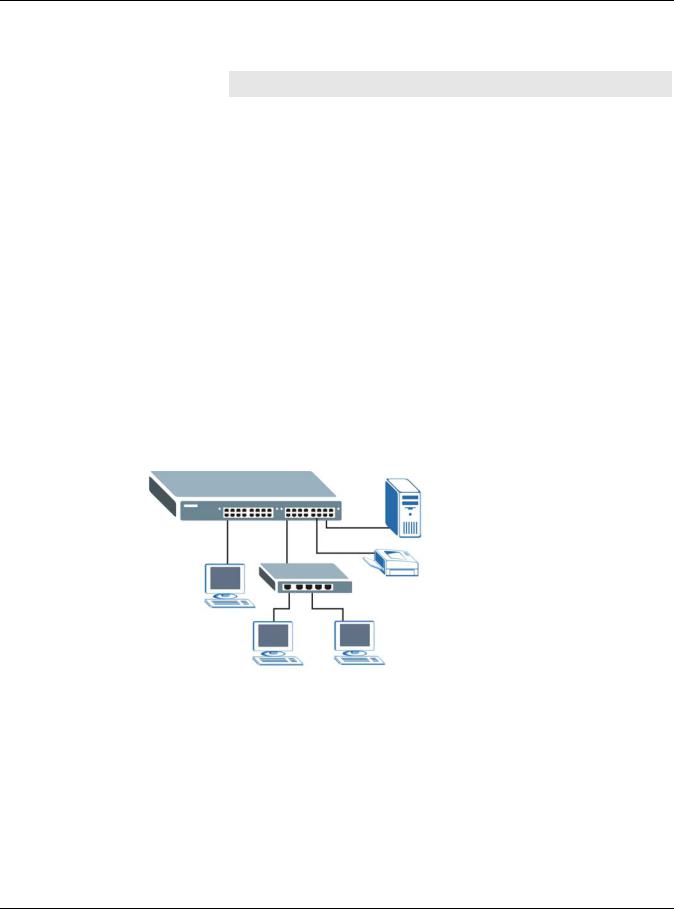
Chapter 1 Getting to Know Your Switch
The following table describes the PoE features of the Switch by model.
Table 2 Models and PoE Features
|
SWITCH MODEL |
POE FEATURES |
|
GS1920-24HP and |
IEEE 802.3af PoE |
|
GS1920-48HP |
|
|
GS1920-24HP and |
IEEE 802.3 at High Power over Ethernet (PoE) |
|
GS1920-48HP |
|
|
GS1920-24HP and |
Power management mode — Classification |
|
GS1920-48HP |
|
|
GS1920-24HP and |
Power management mode — Consumption |
|
GS1920-48HP |
|
This section shows a few examples of using the Switch in various network environments.
1.1.1 Backbone Application
The Switch is an ideal solution for small networks where rapid growth can be expected in the near future. The Switch can be used standalone for a group of heavy traffic users. You can connect computers and servers directly to the Switch’s port or connect other switches to the Switch.
In this example, all computers can share high-speed applications on the server. To expand the network, simply add more networking devices such as switches, routers, computers, print servers etc.
Figure 1 Backbone Application
1.1.2 Bridging Example
In this example, the Switch connects different company departments (RD and Sales) to the corporate backbone. It can alleviate bandwidth contention and eliminate server and network bottlenecks. All users that need high bandwidth can connect to high-speed department servers via the Switch. You can provide a super-fast uplink connection by using a Gigabit Ethernet/mini-GBIC port on the Switch.
Moreover, the Switch eases supervision and maintenance by allowing network managers to centralize multiple servers at a single location.
GS1920 Series User’s Guide
19
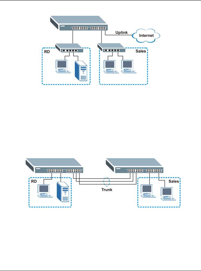
Chapter 1 Getting to Know Your Switch
Figure 2 Bridging Application
1.1.3 High Performance Switching Example
The Switch is ideal for connecting two networks that need high bandwidth. In the following example, use trunking to connect these two networks.
Switching to higher-speed LANs such as ATM (Asynchronous Transmission Mode) is not feasible for most people due to the expense of replacing all existing Ethernet cables and adapter cards, restructuring your network and complex maintenance. The Switch can provide the same bandwidth as ATM at much lower cost while still being able to use existing adapters and switches. Moreover, the current LAN structure can be retained as all ports can freely communicate with each other.
Figure 3 High Performance Switched Workgroup Application
1.1.4 IEEE 802.1Q VLAN Application Examples
A VLAN (Virtual Local Area Network) allows a physical network to be partitioned into multiple logical networks. Stations on a logical network belong to one group. A station can belong to more than one group. With VLAN, a station cannot directly talk to or hear from stations that are not in the same group(s) unless such traffic first goes through a router.
For more information on VLANs, refer to Chapter 9 on page 85.
GS1920 Series User’s Guide
20
![]()
Chapter 1 Getting to Know Your Switch
1.1.4.1 Tag-based VLAN Example
Ports in the same VLAN group share the same frame broadcast domain thus increase network performance through reduced broadcast traffic. VLAN groups can be modified at any time by adding, moving or changing ports without any re-cabling.
Shared resources such as a server can be used by all ports in the same VLAN as the server. In the following figure only ports that need access to the server need to be part of VLAN 1. Ports can belong to other VLAN groups too.
Figure 4 Shared Server Using VLAN Example
1.2 Ways to Manage the Switch
Use any of the following methods to manage the Switch.
•Web Configurator. This is recommended for everyday management of the Switch using a (supported) web browser. See Chapter 4 on page 33.
•FTP. Use FTP for firmware upgrades and configuration backup/restore. See Section 37.7.1 on page 305.
•SNMP. The Switch can be monitored by an SNMP manager. See Section 38.5 on page 315.
•Cluster Management. Cluster Management allows you to manage multiple switches through one switch, called the cluster manager. See Chapter 41 on page 331.
1.3Good Habits for Managing the Switch
Do the following things regularly to make the Switch more secure and to manage the Switch more effectively.
•Change the password. Use a password that’s not easy to guess and that consists of different types of characters, such as numbers and letters.
•Write down the password and put it in a safe place.
GS1920 Series User’s Guide
21

Chapter 1 Getting to Know Your Switch
•Back up the configuration (and make sure you know how to restore it). Restoring an earlier working configuration may be useful if the device becomes unstable or even crashes. If you forget your password, you will have to reset the Switch to its factory default settings. If you backed up an earlier configuration file, you would not have to totally re-configure the Switch. You could simply restore your last configuration. See Section 3.4 on page 30 for how to reset the Switch.
GS1920 Series User’s Guide
22

2
Hardware Installation and Connection
2.1 Installation Scenarios
This chapter shows you how to install and connect the Switch.
The Switch can be placed on a desktop or rack-mounted on a standard EIA rack. Use the rubber feet in a desktop installation and the brackets in a rack-mounted installation.
Note: For proper ventilation, allow at least 4 inches (10 cm) of clearance at the front and 3.4 inches (8 cm) at the back of the Switch. This is especially important for enclosed rack installations.
2.2 Desktop Installation Procedure
1Make sure the Switch is clean and dry.
2Set the Switch on a smooth, level surface strong enough to support the weight of the Switch and the connected cables. Make sure there is a power outlet nearby.
3Make sure there is enough clearance around the Switch to allow air circulation and the attachment of cables and the power cord.
2.3Mounting the Switch on a Rack
The Switch can be mounted on an EIA standard size, 19-inch rack or in a wiring closet with other equipment. Follow the steps below to mount your Switch on a standard EIA rack using a rackmounting kit.
2.3.1Rack-mounted Installation Requirements
•Two mounting brackets.
•Eight M3 flat head screws and a #2 Philips screwdriver.
•Four M5 flat head screws and a #2 Philips screwdriver.
Failure to use the proper screws may damage the unit.
2.3.1.1Precautions
•Make sure the rack will safely support the combined weight of all the equipment it contains.
GS1920 Series User’s Guide
23
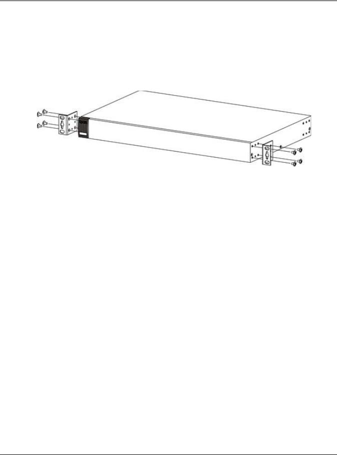
Chapter 2 Hardware Installation and Connection
•Make sure the position of the Switch does not make the rack unstable or top-heavy. Take all necessary precautions to anchor the rack securely before installing the unit.
2.3.2Attaching the Mounting Brackets to the Switch
1Position a mounting bracket on one side of the Switch, lining up the four screw holes on the bracket with the screw holes on the side of the Switch.
Figure 5 Attaching the Mounting Brackets
2Using a #2 Philips screwdriver, install the M3 flat head screws through the mounting bracket holes into the Switch.
3Repeat steps 1 and 2 to install the second mounting bracket on the other side of the Switch.
4You may now mount the Switch on a rack. Proceed to the next section.
2.3.3Mounting the Switch on a Rack
1Position a mounting bracket (that is already attached to the Switch) on one side of the rack, lining up the two screw holes on the bracket with the screw holes on the side of the rack.
GS1920 Series User’s Guide
24
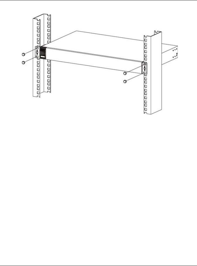
Chapter 2 Hardware Installation and Connection
Figure 6 Mounting the Switch on a Rack
2Using a #2 Philips screwdriver, install the M5 flat head screws through the mounting bracket holes into the rack.
3Repeat steps 1 and 2 to attach the second mounting bracket on the other side of the rack.
GS1920 Series User’s Guide
25
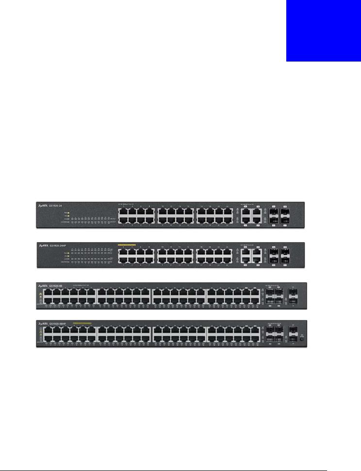
3
Hardware Panels
This chapter describes the front panel and rear panel of the Switch and shows you how to make the hardware connections.
3.1 Front Panel
The following figures show the front panels of the Switch. See Section 3.3 on page 30 for information on the LEDs.
Figure 7 Front Panel: GS1920-24
Figure 8 Front Panel: GS1920-24HP
Figure 9 Front Panel: GS1920-48
Figure 10 Front Panel: GS1920-48HP
3.1.1 Gigabit Ethernet Ports
The Switch has 1000Base-T auto-negotiating, auto-crossover Ethernet ports. In 10/100/1000 Mbps Gigabit, the speed can be 10 Mbps, 100 Mbps or 1000 Mbps and the duplex mode can be half duplex or full duplex.
An auto-negotiating port can detect and adjust to the optimum Ethernet speed (10/100/1000 Mbps) and duplex mode (full duplex or half duplex) of the connected device.
An auto-crossover (auto-MDI/MDI-X) port automatically works with a straight-through or crossover Ethernet cable.
GS1920 Series User’s Guide
26

Chapter 3 Hardware Panels
Four 1000Base-T Ethernet ports are paired with a mini-GBIC slot to create a dual personality interface. The Switch uses up to one connection for each mini-GBIC and 1000Base-T Ethernet pair. The mini-GBIC slots have priority over the Gigabit ports. This means that if a mini-GBIC slot and the corresponding GbE port are connected at the same time, the GbE port will be disabled.
Note: The dual personality ports change to fiber mode directly when inserting the fiber module.
When auto-negotiation is turned on, an Ethernet port negotiates with the peer automatically to determine the connection speed and duplex mode. If the peer Ethernet port does not support autonegotiation or turns off this feature, the Switch determines the connection speed by detecting the signal on the cable and using half duplex mode. When the Switch’s auto-negotiation is turned off, an Ethernet port uses the pre-configured speed and duplex mode when making a connection, thus requiring you to make sure that the settings of the peer Ethernet port are the same in order to connect.
3.1.1.1 Default Ethernet Negotiation Settings
The factory default negotiation settings for the Gigabit ports on the Switch are:
•Speed: Auto
•Duplex: Auto
•Flow control: Off
•Link Aggregation: Disabled
3.1.1.2Auto-crossover
All ports are auto-crossover, that is auto-MDIX ports (Media Dependent Interface Crossover), so you may use either a straight-through Ethernet cable or crossover Ethernet cable for all Gigabit port connections. Auto-crossover ports automatically sense whether they need to function as crossover or straight ports, so crossover cables can connect both computers and switches/hubs.
3.1.2 Mini-GBIC Slots
These are slots for mini-GBIC (Gigabit Interface Converter) transceivers. A transceiver is a single unit that houses a transmitter and a receiver. The Switch does not come with transceivers. You must use transceivers that comply with the Small Form-factor Pluggable (SFP) Transceiver MultiSource Agreement (MSA). See the SFF committee’s INF-8074i specification Rev 1.0 for details.
You can change transceivers while the Switch is operating. You can use different transceivers to connect to Ethernet switches with different types of fiber-optic or even copper cable connectors.
To avoid possible eye injury, do not look into an operating fiber-optic module’s connectors.
•Type: SFP connection interface
•Connection speed: 1 Gigabit per second (Gbps)
3.1.2.1Transceiver Installation
Use the following steps to install a mini-GBIC transceiver (SFP module).
GS1920 Series User’s Guide
27
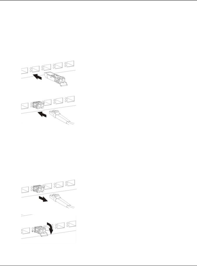
Chapter 3 Hardware Panels
1Insert the transceiver into the slot with the exposed section of PCB board facing down.
2Press the transceiver firmly until it clicks into place.
3The Switch automatically detects the installed transceiver. Check the LEDs to verify that it is functioning properly.
4Close the transceiver’s latch (latch styles vary).
5Connect the fiber optic cables to the transceiver. Figure 11 Transceiver Installation Example
Figure 12 Connecting the Fiber Optic Cables
3.1.2.2Transceiver Removal
Use the following steps to remove a mini-GBIC transceiver (SFP module).
1Remove the fiber optic cables from the transceiver.
2Open the transceiver’s latch (latch styles vary).
3Pull the transceiver out of the slot.
Figure 13 Removing the Fiber Optic Cables
Figure 14 Opening the Transceiver’s Latch Example
GS1920 Series User’s Guide
28

Chapter 3 Hardware Panels
Figure 15 Transceiver Removal Example
3.1.3 LED Mode (only available for GS1920-48HP)
After you push this button (see Section Figure 10 on page 26) to active PoE on the Switch, view the LEDs to ensure proper functioning of the Switch and as an aid in troubleshooting (see Section 3.3 on page 30).
3.2 Rear Panel
The following figures show the rear panels of the Switch.
Figure 16 Rear panel: GS1920-24
Figure 17 Rear Panel: GS1920-24HP
Figure 18 Rear Panel: GS1920-48
Figure 19 Rear Panel: GS1920-48HP
3.2.1 Power Connector
Note: Make sure you are using the correct power source as shown on the panel.
To connect power to the Switch, insert the female end of the power cord to the AC power receptacle on the rear panel. Connect the other end of the supplied power cord to a power outlet. Make sure that no objects obstruct the airflow of the fans (located on the side of the unit).
GS1920 Series User’s Guide
29

Chapter 3 Hardware Panels
3.3 LEDs
After you connect the power to the Switch, view the LEDs to ensure proper functioning of the Switch and as an aid in troubleshooting.
Table 3 LED Descriptions
|
LED |
COLOR |
STATUS |
DESCRIPTION |
|
|
PoE |
Green |
On |
Each Ethernet port’s LED is changed to act as a PoE LED by using the LED |
|
|
(GS1920-48HP |
MODE button on the front panel. |
|||
|
Off |
Each Ethernet port’s LED is changed back to act as a LNK/ACT LED by |
|||
|
only) |
||||
|
releasing the LED MODE button on the front panel. |
||||
|
PWR |
Green |
On |
The system is turned on. |
|
|
Off |
The system is off or has failed. |
|||
|
SYS |
Green |
On |
The system is on and functioning properly. |
|
|
Blinking |
The system is rebooting and performing self-diagnostic tests. |
|||
|
Off |
The power is off or the system is not ready/malfunctioning. |
|||
|
ALM |
Red |
On |
A hardware failure is detected. |
|
|
Off |
The system is functioning normally. |
|||
|
LOCATOR |
Blue |
Blinking |
Shows the actual location of the Switch between several devices in a rack. |
|
|
Ethernet Ports |
||||
|
1-24 (GS1920- |
Green |
Blinking |
The system is transmitting/receiving to/from a 10 Mbps or a 1000 Mbps |
|
|
24/24HP) and |
Ethernet network. |
|||
|
1-48 (GS1920- |
||||
|
On |
The link to a 10 Mbps or a 1000 Mbps Ethernet network is up. |
|||
|
48/48HP) |
||||
|
LNK/ACT |
Amber |
Blinking |
The system is transmitting/receiving to/from a 100 Mbps Ethernet |
|
|
network. |
||||
|
On |
The link to a 100 Mbps Ethernet network is up. |
|||
|
Off |
The link to an Ethernet network is down. |
|||
|
PoE |
Green |
On |
Power supplied to all PoE Ethernet ports meets the IEEE 802.3at |
|
|
(GS1920-24HP |
standard. |
|||
|
Amber |
On |
Power supplied to all PoE Ethernet ports meets the IEEE 802.3af standard. |
||
|
and GS1920- |
||||
|
48HP only) |
||||
|
Off |
There is no power supplied. |
|||
|
Mini-GBIC Slots |
||||
|
25-28 |
Green |
On |
The uplink port is linking at 1000 Mbps. |
|
|
(GS1920-24/ |
||||
|
Blinking |
The system activity is transmitting/receiving data 1000 Mbps. |
|||
|
24HP) and 45- |
||||
|
50 (GS1920- |
Amber |
On |
The uplink port is linking at 100 Mbps. |
|
|
48/48HP) |
||||
|
Blinking |
The system activity is transmitting/receiving data 100 Mbps. |
|||
|
SFP |
||||
|
Off |
There is no link or port, the uplink port is shut down. |
|||
3.4 Reset to Factory Defaults
If you forget your password or cannot access the Web Configurator, you will need to use the Reset button at the side of the device to reload the factory-default configuration file. This means that you will lose all configurations that you had previously and the default Switch IP address, user name and password will be reset to 192.168.1.1, admin and 1234 respectively.
GS1920 Series User’s Guide
30
![]()
Chapter 3 Hardware Panels
If you backed up an earlier configuration file as advised in Section 1.3 on page 21, you will not have to totally re-configure the Switch after resetting. You can simply restore your last configuration.
Follow the steps below to reset the Switch back to factory defaults.
1Make sure the SYS LED is steady green (not blinking). Use a pointed instrument such as a pin to access the Reset button on the side of the Switch as shown in Section 3.4.1 on page 31.
2Press the button for more than five seconds until the SYS LED begins to blink and then release it. Wait for the Switch to restart (the SYS LED will be steady green again). This takes up to two minutes.
Note: If you want to access the Switch web configurator again, you may need to change the IP address of your computer to be in the same subnet as that of the default Switch IP address (192.168.1.1).
3.4.1Side Panels
The reset button is located at the side of the Switch as shown.
Figure 20 Side Panel: GS1920-48
Figure 21 Side Panel: GS1920-24, GS1920-24HP, GS1920-48HP
GS1920 Series User’s Guide
31

PART II
Technical Reference
32

4
The Web Configurator
4.1 Overview
This section introduces the configuration and functions of the web configurator.
The web configurator is an HTML-based management interface that allows easy Switch setup and management via Internet browser. Use Internet Explorer 6.0 and later, Netscape Navigator 7.0 and later, Mozilla Firefox 3.0 and later versions. The recommended screen resolution is 1024 by 768 pixels.
In order to use the web configurator you need to allow:
•Web browser pop-up windows from your device. Web pop-up blocking is enabled by default in Windows XP SP (Service Pack) 2.
•JavaScript (enabled by default).
•Java permissions (enabled by default).
4.2System Login
1Start your web browser.
2Type “http://” and the IP address of the Switch (for example, the default management IP address is 192.168.1.1) in the Location or Address field. Press [ENTER].
3The login screen appears. The default username is admin and associated default password is 1234. The date and time display as shown if you have not configured a time server nor manually entered a time and date in the General Setup screen.
GS1920 Series User’s Guide
33

Chapter 4 The Web Configurator
Figure 22 Web Configurator: Login
4Click OK to view the first web configurator screen.
4.3The Status Screen
The Status screen is the first screen that displays when you access the web configurator.
This guide uses PoE model(s) screens as an example. The screens may very slightly for different models.
The following figure shows the navigating components of a web configurator screen.
Figure 23 Web Configurator Home Screen for PoE model(s) (Status)
B F C D
A
A — Click the menu items to open submenu links, and then click on a submenu link to open the screen in the main window.
B, C, D, E — These are quick links which allow you to perform certain tasks no matter which screen you are currently working in.
B — Click this link to save your configuration into the Switch’s nonvolatile memory. Nonvolatile memory is the configuration of your Switch that stays the same even if the Switch’s power is turned off.
C — Click this link to go to the status page of the Switch.
GS1920 Series User’s Guide
34

Chapter 4 The Web Configurator
D — Click this link to logout of the web configurator.
E — Click this link to display web help pages. The help pages provide descriptions for all of the configuration screens.
F — Click this link to go to the ZON Neighbor Management screen where you can see and manage neighbor devices learned by the Switch.
In the navigation panel, click a main link to reveal a list of submenu links.
Table 4 Navigation Panel Sub-links Overview
|
BASIC SETTING |
ADVANCED APPLICATION |
IP APPLICATION |
MANAGEMENT |
PoE model(s)
The following table describes the links in the navigation panel.
Table 5 Navigation Panel Links
|
LINK |
DESCRIPTION |
|
|
Basic Settings |
||
|
System Info |
This link takes you to a screen that displays general system information. |
|
|
General Setup |
This link takes you to a screen where you can configure general identification information |
|
|
about the Switch. |
||
|
Switch Setup |
This link takes you to a screen where you can set up global Switch parameters such as |
|
|
VLAN type, GARP and priority queues. |
||
|
IP Setup |
This link takes you to a screen where you can configure the IP address, subnet mask |
|
|
(necessary for Switch management) and DNS (domain name server) and set up to 64 IP |
||
|
routing domains. |
||
|
Port Setup |
This link takes you to a screen where you can configure settings for individual Switch ports. |
|
|
GS1920 Series User’s Guide |
35

|
Chapter 4 The Web Configurator |
||
|
Table 5 Navigation Panel Links (continued) |
||
|
LINK |
DESCRIPTION |
|
|
PoE Setup |
For PoE model(s) |
|
|
This link takes you to a screen where you can set priorities so that the Switch is able to |
||
|
reserve and allocate power to certain PDs. |
||
|
Interface Setup |
This link takes you to a screen where you can configure settings for individual interface |
|
|
type and ID. |
||
|
IPv6 |
This link takes you to a screen where you can view IPv6 status and configure IPv6 settings. |
|
|
Advanced Application |
||
|
VLAN |
This link takes you to screens where you can configure port-based or 802.1Q VLAN |
|
|
(depending on what you configured in the Switch Setup menu). You can also configure a |
||
|
protocol based VLAN or a subnet based VLAN in these screens. |
||
|
Static MAC |
This link takes you to a screen where you can configure static MAC addresses for a port. |
|
|
Forwarding |
These static MAC addresses do not age out. |
|
|
Static Multicast |
This link takes you to a screen where you can configure static multicast MAC addresses for |
|
|
Forwarding |
port(s). These static multicast MAC addresses do not age out. |
|
|
Filtering |
This link takes you to a screen to set up filtering rules. |
|
|
Spanning Tree |
This link takes you to screens where you can configure the RSTP/MRSTP/MSTP to prevent |
|
|
Protocol |
network loops. |
|
|
Bandwidth |
This link takes you to a screen where you can configure bandwidth limits on the Switch. |
|
|
Control |
||
|
Broadcast Storm |
This link takes you to a screen to set up broadcast filters. |
|
|
Control |
||
|
Mirroring |
This link takes you to screens where you can copy traffic from one port or ports to another |
|
|
port in order that you can examine the traffic from the first port without interference. |
||
|
Link Aggregation |
This link takes you to screens where you can logically aggregate physical links to form one |
|
|
logical, higher-bandwidth link. |
||
|
Port |
This link takes you to a screen where you can configure IEEE 802.1x port authentication for |
|
|
Authentication |
clients communicating via the Switch. |
|
|
Port Security |
This link takes you to screens where you can activate MAC address learning and set the |
|
|
maximum number of MAC addresses to learn on a port. |
||
|
Classifier |
This link takes you to a screen where you can configure the Switch to group packets based |
|
|
on the specified criteria. |
||
|
Policy Rule |
This link takes you to a screen where you can configure the Switch to perform special |
|
|
treatment on the grouped packets. |
||
|
Queuing Method |
This link takes you to a screen where you can configure queuing with associated queue |
|
|
weights for each port. |
||
|
Multicast |
This link takes you to screens where you can configure various multicast features, IGMP |
|
|
snooping and create multicast VLANs. |
AAAThis link takes you to a screen where you can configure authentication, authorization services via external servers. The external servers can be either RADIUS (Remote Authentication Dial-In User Service) or TACACS+ (Terminal Access Controller AccessControl System Plus).
|
IP Source Guard |
This link takes you to screens where you can configure filtering of unauthorized DHCP and |
|
|
ARP packets in your network. |
||
|
Loop Guard |
This link takes you to a screen where you can configure protection against network loops |
|
|
that occur on the edge of your network. |
||
|
Layer 2 Protocol |
This link takes you to a screen where you can configure L2PT (Layer 2 Protocol Tunneling) |
|
|
Tunneling |
settings on the Switch. |
|
|
PPPoE |
This link takes you to a screen where you can configure intermediate agent settings in |
|
|
port, VLAN, and PPPoE. |
||
|
GS1920 Series User’s Guide |
36

|
Chapter 4 The Web Configurator |
||
|
Table 5 Navigation Panel Links (continued) |
||
|
LINK |
DESCRIPTION |
|
|
Errdisable |
This link takes you to a screen where you can configure errdisable settings in CPU |
|
|
protection, errdisable detect, and errdisable recovery. |
||
|
Private VLAN |
This link takes you to a screen where you can configure private VLANs. |
|
|
Green Ethernet |
This link takes you to a screen where you can configure green Ethernet settings in EEE, |
|
|
auto power down, abd short reach for each port. |
||
|
LLDP |
This link takes you to a screen where you can configure LLDP settings. |
|
|
IP Application |
||
|
Static Routing |
This link takes you to a screen where you can configure static routes. A static route defines |
|
|
how the Switch should forward traffic by configuring the TCP/IP parameters manually. |
||
|
DiffServ |
This link takes you to screens where you can enable DiffServ, configure marking rules and |
|
|
set DSCP-to-IEEE802.1p mappings. |
||
|
DHCP |
This link takes you to screens where you can configure the DHCP settings. |
|
|
ARP Setup |
This link takes you to screens where you can configure the ARP learning settings for each |
|
|
port. |
||
|
Management |
||
|
Maintenance |
This link takes you to screens where you can perform firmware and configuration file |
|
|
maintenance as well as reboot the system. |
||
|
Access Control |
This link takes you to screens where you can change the system login password and |
|
|
configure SNMP and remote management. |
||
|
Diagnostic |
This link takes you to a screen where you can view system logs and test port(s). |
|
|
Syslog |
This link takes you to screens where you can setup system logs and a system log server. |
|
|
Cluster |
This link takes you to screens where you can configure clustering management and view its |
|
|
Management |
status. |
|
|
MAC Table |
This link takes you to a screen where you can view the MAC addresses (and types) of |
|
|
devices attached to what ports and VLAN IDs. |
||
|
ARP Table |
This link takes you to a screen where you can view the MAC addresses – IP address |
|
|
resolution table. |
||
|
Path MTU Table |
This link takes you to a screen where you can view the path MTU aging time, index, |
|
|
destination address, MTU, and expire settings. |
||
|
Configure Clone |
This link takes you to a screen where you can copy attributes of one port to other ports. |
|
|
Neighbor Table |
This link takes you to a screen where you can view the IPv6 neighbor table which includes |
|
|
index, interface, neighbor address, MAC address, status and type. |
||
4.3.1 Change Your Password
After you log in for the first time, it is recommended you change the default administrator password. Click Management > Access Control > Logins to display the next screen.
GS1920 Series User’s Guide
37

Chapter 4 The Web Configurator
Figure 24 Change Administrator Login Password
4.4 Saving Your Configuration
When you are done modifying the settings in a screen, click Apply to save your changes back to the run-time memory. Settings in the run-time memory are lost when the Switch’s power is turned off.
Click the Save link in the upper right hand corner of the web configurator to save your configuration to nonvolatile memory. Nonvolatile memory refers to the Switch’s storage that remains even if the Switch’s power is turned off.
Note: Use the Save link when you are done with a configuration session.
4.5 Switch Lockout
You could block yourself (and all others) from managing the Switch if you do one of the following:
1Delete the management VLAN (default is VLAN 1).
2Delete all port-based VLANs with the CPU port as a member. The “CPU port” is the management port of the Switch.
3Filter all traffic to the CPU port.
4Disable all ports.
GS1920 Series User’s Guide
38

Chapter 4 The Web Configurator
5Misconfigure the text configuration file.
6Forget the password and/or IP address.
7Prevent all services from accessing the Switch.
8Change a service port number but forget it.
Note: Be careful not to lock yourself and others out of the Switch.
4.6Resetting the Switch
If you lock yourself (and others) from the Switch or forget the administrator password, you will need to reset the Switch back to the factory defaults (see Section 3.4 on page 30).
4.7 Logging Out of the Web Configurator
Click Logout in a screen to exit the web configurator. You have to log in with your password again after you log out. This is recommended after you finish a management session for security reasons.
Figure 25 Web Configurator: Logout Screen
4.8 Help
The web configurator’s online help has descriptions of individual screens and some supplementary information.
Click the Help link from a web configurator screen to view an online help description of that screen.
GS1920 Series User’s Guide
39

5
Initial Setup Example
5.1 Overview
This chapter shows how to set up the Switch for an example network.
The following lists the configuration steps for the initial setup:
•Create a VLAN
•Set port VLAN ID
•Configure the Switch IP management address
5.1.1Creating a VLAN
VLANs confine broadcast frames to the VLAN group in which the port(s) belongs. You can do this with port-based VLAN or tagged static VLAN with fixed port members.
In this example, you want to configure port 1 as a member of VLAN 2.
Figure 26 Initial Setup Network Example: VLAN
1Click Advanced Application > VLAN > VLAN Configuration in the navigation panel and click the Static VLAN Setup link.
GS1920 Series User’s Guide
40
![]()
Chapter 5 Initial Setup Example
2In the Static VLAN screen, select ACTIVE, enter a descriptive name in the Name field and enter 2 in the VLAN Group ID field for the VLAN2 network.
Note: The VLAN Group ID field in this screen and the VID field in the IP Setup screen refer to the same VLAN ID.
3Since the VLAN2 network is connected to port 1 on the Switch, select Fixed to configure port 1 to be a permanent member of the VLAN only.
4To ensure that VLAN-unaware devices (such as computers and hubs) can receive frames properly, clear the TX Tagging check box to set the Switch to remove VLAN tags before sending.
5Click Add to save the settings to the run-time memory. Settings in the run-time memory are lost when the Switch’s power is turned off.
5.1.2Setting Port VID
Use PVID to add a tag to incoming untagged frames received on that port so that the frames are forwarded to the VLAN group that the tag defines.
In the example network, configure 2 as the port VID on port 1 so that any untagged frames received on that port get sent to VLAN 2.
GS1920 Series User’s Guide
41

Chapter 5 Initial Setup Example
Figure 27 Initial Setup Network Example: Port VID
1Click Advanced Applications > VLAN > VLAN Configuration in the navigation panel. Then click the VLAN Port Setup link.
2Enter 2 in the PVID field for port 2 and click Apply to save your changes back to the runtime memory. Settings in the run-time memory are lost when the Switch’s power is turned off.
5.2Configuring Switch Management IP Address
The default management IP address of the Switch is 192.168.1.1. You can configure another IP address in a different subnet for management purposes. The following figure shows an example.
Figure 28 Initial Setup Example: Management IP Address
1Connect your computer to any Ethernet port on the Switch. Make sure your computer is in the same subnet as the Switch.
2Open your web browser and enter 192.168.1.1 (the default IP address) in the address bar to access the web configurator. See Section 4.2 on page 33 for more information.
GS1920 Series User’s Guide
42

Chapter 5 Initial Setup Example
3Click Basic Setting > IP Setup in the navigation panel.
4Configure the related fields in the IP Setup screen.
5For the VLAN2 network, enter 192.168.2.1 as the IP address and 255.255.255.0 as the subnet mask.
6 In the VID field, enter the ID of the VLAN group to which you want this management IP address to belong. This is the same as the VLAN ID you configure in the Static VLAN screen.
7Click Add to save your changes back to the runtime memory. Settings in the run-time memory are lost when the Switch’s power is turned off.
GS1920 Series User’s Guide
43

6
Tutorials
6.1 Overview
This chapter provides some examples of using the web configurator to set up and use the Switch. The tutorials include:
•How to Use DHCP Snooping on the Switch
•How to Use DHCP Relay on the Switch
6.2How to Use DHCP Snooping on the Switch
You only want DHCP server A connected to port 5 to assign IP addresses to all devices in VLAN network (V). Create a VLAN containing ports 5, 6 and 7. Connect a computer M to the Switch for management.
Figure 29 Tutorial: DHCP Snooping Tutorial Overview
M
V

 C
C  B
B  A
A
Note: For related information about DHCP snooping, see Section 25.1 on page 200.
The settings in this tutorial are as the following.
Table 6 Tutorial: Settings in this Tutorial
|
HOST |
PORT CONNECTED |
VLAN |
PVID |
DHCP SNOOPING PORT TRUSTED |
|
DHCP Server (A) |
5 |
1 and 100 |
100 |
Yes |
|
DHCP Client (B) |
6 |
1 and 100 |
100 |
No |
|
DHCP Client (C) |
7 |
1 and 100 |
100 |
No |
1Access the Switch through http://192.168.1.1 by default. Log into the Switch by entering the username (default: admin) and password (default: 1234).
GS1920 Series User’s Guide
44

Chapter 6 Tutorials
2Go to Advanced Application > VLAN > VLAN Configuration > Static VLAN Setup, and create a VLAN with ID of 100. Add ports 5, 6 and 7 in the VLAN by selecting Fixed in the Control field as shown.
Deselect Tx Tagging because you don’t want outgoing traffic to contain this VLAN tag. Click Add.
Figure 30 Tutorial: Create a VLAN and Add Ports to It
3Go to Advanced Application > VLAN > VLAN Configuration > VLAN Port Setup, and set the PVID of the ports 5, 6 and 7 to 100. This tags untagged incoming frames on ports 5, 6 and 7 with the tag 100.
GS1920 Series User’s Guide
45

Chapter 6 Tutorials
|
Figure 31 |
Tutorial: Tag Untagged Frames |
4Go to Advanced Application > IP Source Guard > DHCP snooping > Configure, activate and specify VLAN 100 as the DHCP VLAN as shown. Click Apply.
Figure 32 Tutorial: Specify DHCP VLAN
5 Click the Port link at the top right corner.
GS1920 Series User’s Guide
46

Chapter 6 Tutorials
6The DHCP Snooping Port Configure screen appears. Select Trusted in the Server Trusted state field for port 5 because the DHCP server is connected to port 5. Keep ports 6 and 7 Untrusted because they are connected to DHCP clients. Click Apply.
Figure 33 Tutorial: Set the DHCP Server Port to Trusted
7Go to Advanced Application > IP Source Guard > DHCP snooping > Configure > VLAN, show VLAN 100 by entering 100 in the Start VID and End VID fields and click Apply. Then select Yes in the Enabled field of the VLAN 100 entry shown at the bottom section of the screen.
If you want to add more information in the DHCP request packets such as source VLAN ID or system name, you can also select the Option82 Profile field in the entry. See Section 25.10.1.3 on page 220.
Figure 34 Tutorial: Enable DHCP Snooping on this VLAN
8Click Save at the top right corner of the web configurator to save the configuration permanently.
9Connect your DHCP server to port 5 and a computer (as DHCP client) to either port 6 or 7. The computer should be able to get an IP address from the DHCP server. If you put the DHCP server on port 6 or 7, the computer will not able to get an IP address.
10To check if DHCP snooping works, go to Advanced Application > IP Source Guard, you should see an IP assignment with the type DHCP-Snooping as shown.
GS1920 Series User’s Guide
47

Chapter 6 Tutorials
Figure 35 Tutorial: Check the Binding If DHCP Snooping Works
6.3 How to Use DHCP Relay on the Switch
This tutorial describes how to configure your Switch to forward DHCP client requests to a specific DHCP server. The DHCP server can then assign a specific IP address based on the information in the DHCP requests.
6.3.1 DHCP Relay Tutorial Introduction
In this example, you have configured your DHCP server (192.168.2.3) and want to have it assign a specific IP address (say 172.16.1.18) to DHCP client A based on the system name, VLAN ID and port number in the DHCP request. Client A connects to the Switch’s port 2 in VLAN 102.
Figure 36 Tutorial: DHCP Relay Scenario
|
DHCP Server |
Port 2 |
|
192.168.2.3 |
|
|
PVID=102 |
A
VLAN 102
172.16.1.18
6.3.2 Creating a VLAN
Follow the steps below to configure port 2 as a member of VLAN 102.
1Access the web configurator through the Switch’s management port.
2Go to Basic Setting > Switch Setup and set the VLAN type to 802.1Q. Click Apply to save the settings to the run-time memory.
GS1920 Series User’s Guide
48

Chapter 6 Tutorials
Figure 37 Tutorial: Set VLAN Type to 802.1Q
3Click Advanced Application > VLAN > VLAN Configuration > Static VLAN Setup.
4In the Static VLAN screen, select ACTIVE, enter a descriptive name (VLAN 102 for example) in the Name field and enter 102 in the VLAN Group ID field.
5Select Fixed to configure port 2 to be a permanent member of this VLAN.
6Clear the TX Tagging check box to set the Switch to remove VLAN tags before sending.
7Click Add to save the settings to the run-time memory. Settings in the run-time memory are lost when the Switch’s power is turned off.
Figure 38 Tutorial: Create a Static VLAN
GS1920 Series User’s Guide
49

Chapter 6 Tutorials
8Click the VLAN Configuration link in the Static VLAN screen and then the VLAN Port Setup link in the VLAN Configuration screen.
Figure 39 Tutorial: Click the VLAN Port Setting Link
9Enter 102 in the PVID field for port 2 to add a tag to incoming untagged frames received on that port so that the frames are forwarded to the VLAN group that the tag defines.
10Click Apply to save your changes back to the run-time memory. Figure 40 Tutorial: Add Tag for Frames Received on Port 2
11Click the Save link in the upper right corner of the web configurator to save your configuration permanently.
6.3.3Configuring DHCP Relay
Follow the steps below to enable DHCP relay on the Switch and allow the Switch to add relay agent information (such as the VLAN ID) to DHCP requests.
1Click IP Application > DHCP > DHCPv4 and then the Global link to open the DHCP Relay screen.
2Select the Active check box.
3Enter the DHCP server’s IP address (192.168.2.3 in this example) in the Remote DHCP Server 1 field.
4Select default1 or default2 in the Option 82 Profile field.
GS1920 Series User’s Guide
50
 Loading…