Для ознакомления с инструкцией необходимо нажать на ссылку «ЗАГРУЗИТЬ», чтобы скачать pdf файл. Если есть кнопка «ПРОСМОТР», то можно просто посмотреть документ онлайн.
Для удобства, Вы можете сохранить данную страницу с файлом руководства по эксплуатации в свой список «избранное» прямо на сайте (доступно для зарегистрированных пользователей).
Смотрите инструкцию для похожих моделей:

Вы можете задать вопрос посетителям сайта по модели ZYXEL VMG3312-T20A. Если Вы являетесь её пользователем, то пожалуйста оставьте, по возможности развёрнутый отзыв:
-
Contents
-
Table of Contents
-
Troubleshooting
-
Bookmarks
Quick Links
User’s Guide
VMG3312-T20A
Wireless N VDSL2 Combo WAN Gateway with USB
Default Login Details
LAN IP Address
Login
Password
Copyright © 2017 Zyxel Communications Corporation
http://192.168.1.1
admin, user
1234, user
Version 5.30 Edition 1, 03/2017
Related Manuals for ZyXEL Communications VMG3312-T20A
Summary of Contents for ZyXEL Communications VMG3312-T20A
-
Page 1
User’s Guide VMG3312-T20A Wireless N VDSL2 Combo WAN Gateway with USB Default Login Details Version 5.30 Edition 1, 03/2017 LAN IP Address http://192.168.1.1 Login admin, user Password 1234, user Copyright © 2017 Zyxel Communications Corporation… -
Page 2: Related Documentation
Every effort has been made to ensure that the information in this manual is accurate. Related Documentation • Quick Start Guide The Quick Start Guide shows how to connect the managed device. • More Information Go to support.zyxel.com to find other information on the VMG VMG3312-T20A User’s Guide…
-
Page 3: Table Of Contents
Cellular Statistics ……………………..228 System …………………………230 User Account ……………………….231 Remote Management ……………………234 SNMP …………………………237 Time Settings ……………………….239 E-mail Notification ……………………..241 Logs Setting ……………………….243 Firmware Upgrade ……………………..246 Backup/Restore ……………………..248 Diagnostic ……………………….251 VMG3312-T20A User’s Guide…
-
Page 4
Contents Overview Troubleshooting ……………………..253 Appendices ………………………..259 VMG3312-T20A User’s Guide… -
Page 5: Table Of Contents
2.1.1 Accessing the Web Configurator ………………26 2.2 Web Configurator Layout ………………….28 2.2.1 Title Bar ……………………… 28 2.2.2 Main Window ……………………. 28 2.2.3 Navigation Panel ……………………29 Chapter 3 Quick Start ……………………….33 3.1 Overview ……………………….33 3.2 Quick Start Setup ……………………..33 VMG3312-T20A User’s Guide…
-
Page 6
6.1 Overview ……………………….70 6.1.1 What You Can Do in this Chapter ………………70 6.1.2 What You Need to Know ………………… 71 6.1.3 Before You Begin ……………………74 6.2 The Broadband Screen ……………………74 6.2.1 Add/Edit Internet Connection ………………… 75 VMG3312-T20A User’s Guide… -
Page 7
8.4 The UPnP Screen ……………………… 130 8.4.1 Turning On UPnP in Windows 7 Example …………….131 8.5 The Additional Subnet Screen ………………… 133 8.6 The STB Vendor ID Screen ………………….134 8.7 The Wake on LAN Screen ………………….134 VMG3312-T20A User’s Guide… -
Page 8
11.1.1 What You Can Do in this Chapter ………………. 163 11.1.2 What You Need To Know ………………..163 11.2 The Port Forwarding Screen ………………… 164 11.2.1 Add/Edit Port Forwarding ………………..166 11.3 The Applications Screen ………………….167 VMG3312-T20A User’s Guide… -
Page 9
14.1.3 Before You Begin ………………….. 189 14.2 The File Sharing Screen ………………….189 14.2.1 The Add New Share Screen ………………… 191 14.2.2 The Add New User Screen ………………..192 14.3 The Media Server Screen ………………….192 Chapter 15 Firewall …………………………193 VMG3312-T20A User’s Guide… -
Page 10
19.4 The Trusted CA Screen ………………….. 213 19.4.1 View Trusted CA Certificate ……………….. 214 19.4.2 Import Trusted CA Certificate ………………215 Chapter 20 Log …………………………216 20.1 Overview ……………………….. 216 20.1.1 What You Can Do in this Chapter ………………. 216 VMG3312-T20A User’s Guide… -
Page 11
Chapter 26 System………………………….230 26.1 Overview ……………………….. 230 26.2 The System Screen ……………………230 Chapter 27 User Account……………………….231 27.1 Overview ………………………. 231 27.2 The User Account Screen ………………….231 27.2.1 The User Account Add and Edit Screens …………… 232 VMG3312-T20A User’s Guide… -
Page 12
33.1 Overview ……………………….. 246 33.2 The Firmware Screen ……………………246 Chapter 34 Backup/Restore ……………………..248 34.1 Overview ……………………….. 248 34.2 The Backup/Restore Screen …………………. 248 34.3 The Reboot Screen ……………………250 Chapter 35 Diagnostic……………………….251 35.1 Overview ……………………….. 251 VMG3312-T20A User’s Guide… -
Page 13
36.6 UPnP ……………………….. 258 Part III: Appendices ………………259 Appendix A Customer Support ………………… 260 Appendix B Wireless LANs………………….. 266 Appendix C IPv6……………………..279 Appendix D Services ……………………287 Appendix E Legal Information ………………….. 291 Index …………………………299 VMG3312-T20A User’s Guide… -
Page 14: User’s Guide
User’s Guide…
-
Page 15: Introducing The Vmg
VMG to its factory default settings. If you backed up an earlier configuration file, you would not have to totally re-configure the VMG. You could simply restore your last configuration. VMG3312-T20A User’s Guide…
-
Page 16: Applications For The Vmg
Note: The ADSL and VDSL lines share the same WAN (layer-2) interfaces that you configure in the VMG. Refer to Section 6.2 on page 74 for the Network Setting > Broadband screen. Figure 1 VMG’s Internet Access Application: DSL VMG3312-T20A User’s Guide…
-
Page 17: Vmg’s Usb Support
To update the supported cellular USB dongle list, download the latest WWAN package from the Zyxel website and upload it to the VMG using the Maintenance > Firmware Upgrade screen. Figure 3 VMG’s Internet Access Application: Cellular WAN VMG3312-T20A User’s Guide…
-
Page 18: File Sharing
You can also use the VMG as a media server. This lets anyone on your network play video, music, and photos from a USB device (B) connected to the VMG’s USB port (without having to copy them to another computer). Figure 5 USB Media Server Application VMG3312-T20A User’s Guide…
-
Page 19: Wireless Access
Section 1.6.4 on page 23 for more information about how to set up a wireless network with WLAN and WPS buttons. Figure 6 Wireless Access Example 1.6 Hardware 1.6.1 Front Panel The following graphic displays the front panel of the VMG. VMG3312-T20A User’s Guide…
-
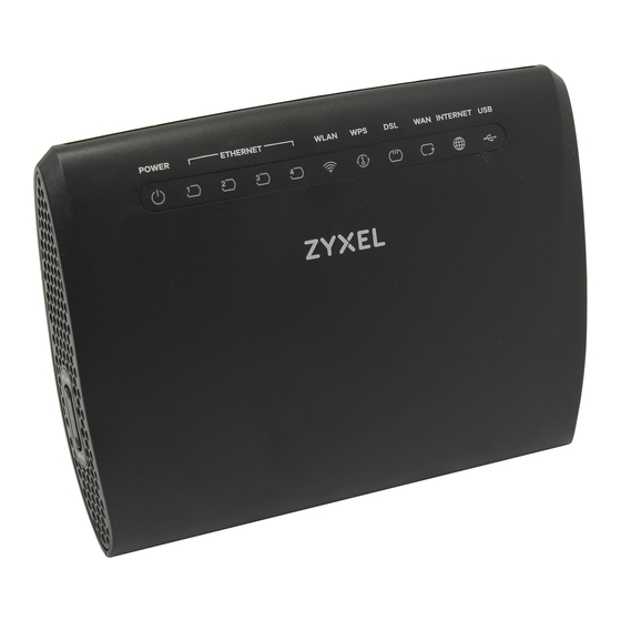
Page 20: Leds (Lights)
Chapter 1 Introducing the VMG Figure 7 VMG3312-T20A Front Panel 1.6.2 LEDs (Lights) The following graphic displays the labels of the LEDs. Figure 8 LEDs on the VMG None of the LEDs are on if the VMG is not receiving power.
-
Page 21: Side Panels
The VMG is sending/receiving data to/from the USB device connected to it. The VMG does not detect a USB connection through the USB slot. 1.6.3 Side Panels The following graphics display the side panels of the VMG. VMG3312-T20A User’s Guide…
-
Page 22
Chapter 1 Introducing the VMG Figure 9 VMG3312-T20A Side Panel Figure 10 VMG3312-T20A Side Panel The following table describes the items on the side panels.. Table 2 Side Panel Buttons LABEL DESCRIPTION WLAN Press the WLAN button for more than two seconds to enable the wireless function. -
Page 23: Using The Wi-Fi And Wps Buttons
To turn off the wireless network, press the WLAN button for more than two seconds. The WLAN LED turns off when the wireless network is off. 1.6.5 Rear Panel The following graphic displays the rear panel of the VMG. Figure 11 VMG3312-T20A Rear Panel VMG3312-T20A User’s Guide…
-
Page 24: The Reset Button
Make sure the screws are fastened well enough to hold the weight of the VMG with the connection cables. Align the holes on the back of the VMG with the screws on the wall. Hang the VMG on the screws. VMG3312-T20A User’s Guide…
-
Page 25
Chapter 1 Introducing the VMG Figure 12 Wall Mounting Example VMG3312-T20A User’s Guide… -
Page 26: The Web Configurator
1234 in the password screen and click Login. If you have changed the password, enter your password and click Login. Figure 13 Password Screen The following screen displays if you have not yet changed your password. Enter a new password, retype it to confirm and click Apply. VMG3312-T20A User’s Guide…
-
Page 27
After you finished or closed the Quick Start Wizard screen, the Network Map page appears. Figure 15 Network Map Click the right arrow icon to display the Status screen, where you can view the VMG’s interface and system information. VMG3312-T20A User’s Guide… -
Page 28: Web Configurator Layout
Quick Start: Click this icon to open screens where you can configure the VMG’s time zone Internet access, and wireless settings. Logout: Click this icon to log out of the web configurator. 2.2.2 Main Window The main window displays information and configuration fields. It is discussed in the rest of this document. VMG3312-T20A User’s Guide…
-
Page 29: Navigation Panel
Use this screen to forward DNS queries for certain domain names through a specific WAN interface to its DNS server(s). Policy Route Use this screen to configure policy routing on the VMG. Use this screen to configure Routing Information Protocol to exchange routing information with other routers. VMG3312-T20A User’s Guide…
-
Page 30
(such as parental control) is enforced. Certificates Local Certificates Use this screen to view a summary list of certificates and manage certificates and certification requests. Trusted CA Use this screen to view and manage the list of the trusted CAs. System Monitor VMG3312-T20A User’s Guide… -
Page 31
Use this screen to change your VMG’s log settings. Firmware Firmware Use this screen to upload firmware to your VMG. Upgrade Upgrade Backup Restore Backup/Restore Use this screen to backup and restore your VMG’s configuration (settings) or reset the factory default settings. VMG3312-T20A User’s Guide… -
Page 32
Use this screen to reboot the VMG without turning the power off. Diagnostic Ping&Traceroute Use this screen to identify problems with the DSL connection. You can &Nslookup use Ping, TraceRoute, or Nslookup to help you identify problems. VMG3312-T20A User’s Guide… -
Page 33: Quick Start
Select the time zone of your location. Click Next. Figure 17 Quick Start — Welcome Enter your Internet connection information in this screen. The screen and fields to enter may vary depending on your current connection type. Click Next. VMG3312-T20A User’s Guide…
-
Page 34
Turn the wireless LAN on or off. If you keep it on, record the security settings so you can configure your wireless clients to connect to the VMG. Click Save. Figure 19 Quick Start — Wireless Setting Your VMG saves your settings and attempts to connect to the Internet. Click Close to complete the setup. VMG3312-T20A User’s Guide… -
Page 35
Chapter 3 Quick Start Figure 20 Quick Start — Result Summary VMG3312-T20A User’s Guide… -
Page 36: Tutorials
Service Provider (ISP) to configure the VMG. Be sure to contact your service provider for any information you need to configure the Broadband screens. Click Network Setting > Broadband to open the following screen. Click Add New WAN Interface. VMG3312-T20A User’s Guide…
-
Page 37
Then select DNS as Static and enter the DNS server addresses provided to you, such as 192.168.5.2 (DNS server1)/192.168.5.1 (DNS server2). Leave the rest of the fields to the default settings. Click Apply to save your settings. VMG3312-T20A User’s Guide… -
Page 38
Chapter 4 Tutorials You should see a summary of your new DSL connection setup in the Broadband screen as follows. VMG3312-T20A User’s Guide… -
Page 39: Setting Up A Secure Wireless Network
802.11b/g/n Mixed Click Network Setting > Wireless to open the General screen. Select More Secure as the security level and WPA2-PSK as the security mode. Configure the screen using the provided parameters (see page 39). Click Apply. VMG3312-T20A User’s Guide…
-
Page 40
Thomas can now use the WPS feature to establish a wireless connection between his notebook and the VMG (see Section 4.3.2 on page 41). He can also use the notebook’s wireless client to search for the VMG (see Section 4.3.3 on page 44). VMG3312-T20A User’s Guide… -
Page 41: Using Wps
Both buttons have exactly the same function: you can use one or the other. Note: It doesn’t matter which button is pressed first. You must press the second button within two minutes of pressing the first one. VMG3312-T20A User’s Guide…
-
Page 42
Launch your wireless client’s configuration utility. Go to the WPS settings and select the PIN method to get a PIN number. Log into VMG’s web configurator and go to the Network Setting > Wireless > WPS screen. Enable the WPS function and click Apply. VMG3312-T20A User’s Guide… -
Page 43
This may take up to two minutes. The wireless client is then able to communicate with the VMG securely. The following figure shows you how to set up a wireless network and its security on a VMG and a wireless client by using PIN method. VMG3312-T20A User’s Guide… -
Page 44: Without Wps
4.4 Setting Up Multiple Wireless Groups Company A wants to create different wireless network groups for different types of users as shown in the following figure. Each group has its own SSID and security mode. VMG3312-T20A User’s Guide…
-
Page 45
Pre-Shared Key ForCompanyOnly 123456789 guest123 Click Network Setting > Wireless to open the General screen. Use this screen to set up the company’s general wireless network group. Configure the screen using the provided parameters and click Apply. VMG3312-T20A User’s Guide… -
Page 46
Chapter 4 Tutorials Click Network Setting > Wireless > Guest/More AP to open the following screen. Click the Edit icon to configure the second wireless network group. Configure the screen using the provided parameters and click Apply. VMG3312-T20A User’s Guide… -
Page 47
Chapter 4 Tutorials In the Guest/More AP screen, click the Edit icon to configure the third wireless network group.Configure the screen using the provided parameters and click Apply. VMG3312-T20A User’s Guide… -
Page 48: Using The File Sharing Feature
• Access the shared files of your USB device from a computer. 4.5.1 Set Up File Sharing To set up file sharing you need to connect your USB device, enable file sharing and set up your share(s). VMG3312-T20A User’s Guide…
-
Page 49
Click Add New Share in the File Sharing screen to add a new share. Select your USB device from the Volume drop-down list box. Click Browse to browse through all the files on your USB device. Select the folder that you want to add as a share. In this example, select BobShare. Click Apply. VMG3312-T20A User’s Guide… -
Page 50
For detailed information, please refer to the steps below. The Add Share Directory screen should look like the following. Click Apply to finish. This sets up the file sharing server. You can see the USB storage device listed in the table below. VMG3312-T20A User’s Guide… -
Page 51: Access Your Shared Files From A Computer
This section shows you how the media server feature works using the following media clients: • Microsoft (MS) Windows Media Player Media Server works with Windows 7. Make sure your computer is able to play media files (music, videos and pictures). VMG3312-T20A User’s Guide…
-
Page 52: Configuring The Vmg
4.6.2 Using Windows Media Player This section shows you how to play the media files on the USB storage device connected to your VMG using Windows Media Player. Windows 7 Open Windows Media Player. It should automatically detect the VMG. VMG3312-T20A User’s Guide…
-
Page 53
Music/Videos/Pictures/Recorded TV > Add > \192.168.1.1BobShare. (Select the folder containing the media you wish to upload to Windows Media Player.) In the right panel, you should see a list of files available in the USB storage device. VMG3312-T20A User’s Guide… -
Page 54: Using A Digital Media Adapter
Connect the DMA-2500 to an available LAN port in your VMG. Turn on the TV and wait for the DMA-2500 Home screen to appear. Using the remote control, go to MyMedia to open the following screen. Select the GPON Device as your media server. VMG3312-T20A User’s Guide…
-
Page 55: Configuring Static Route For Routing To Another Network
(192.168.1.x/24) and N2 (192.168.10.x/24). If you want to send traffic from computer A (in N1 network) to computer B (in N2 network), the traffic is sent to the VMG’s WAN default gateway by default. In this case, B will never receive the traffic. VMG3312-T20A User’s Guide…
-
Page 56
N2. In this case, the VMG routes traffic from A to R and then R routes the traffic to B. This tutorial uses the following example IP settings: Table 7 IP Settings in this Tutorial DEVICE / COMPUTER IP ADDRESS The VMG’s WAN 172.16.1.1 The VMG’s LAN 192.168.1.1 IP Type IPv4 Use Interface VDSL 192.168.1.34 VMG3312-T20A User’s Guide… -
Page 57
Gateway IP Address field. Select VDSL as the Use Interface. Click OK. Now B should be able to receive traffic from A. You may need to additionally configure B’s firewall settings to allow specific traffic to pass through. VMG3312-T20A User’s Guide… -
Page 58: Configuring Qos Queue And Class Setup
10,000 kbps (or leave this blank to have the VMG automatically determine this figure). Click Apply. Tutorial: Advanced > QoS Click Queue Setup > Edit to modify a queue. Enter or select the following values: • Name: E-mail • Interface: WAN VMG3312-T20A User’s Guide…
-
Page 59
• Weight: 8 Tutorial: Advanced > QoS > Queue Setup Click Classification Setup > Add new Classification to create a new class. Select Enable in the Active field and follow the settings as shown in the screen below. VMG3312-T20A User’s Guide… -
Page 60
This maps e-mail traffic coming from port 25 to the highest priority, which you have created in the previous screen (see the IP Protocol field). This also maps your computer’s IP address and MAC address to the E-mail queue (see the Source fields). VMG3312-T20A User’s Guide… -
Page 61: Access The Vmg Using Ddns
Then you will need to configure the same account and host name on the VMG later. 4.9.2 Configuring DDNS on Your VMG Configure the following settings in the Network Setting > DNS > Dynamic DNS screen. • Select Enable Dynamic DNS. • Select www.DynDNS.com as the service provider. VMG3312-T20A User’s Guide…
-
Page 62: Testing The Ddns Setting
Josephine’s computer connects wirelessly to the Internet through the VMG. Thomas decides to use the Security > MAC Filter screen to grant wireless network access to his computer but not to Josephine’s computer. VMG3312-T20A User’s Guide…
-
Page 63: Access Your Shared Files From A Computer
4.11 Access Your Shared Files From a Computer Here is how to use an FTP program to access a file storage device connected to the VMG’s USB port. Note: This example uses the FileZilla FTP program to browse your shared files. VMG3312-T20A User’s Guide…
-
Page 64
In FileZilla enter the IP address of the VMG (the default is 192.168.1.1), your account’s user name and password and port 21 and click Quickconnect. A screen asking for password authentication appears. File Sharing via Windows Explorer Once you log in the USB device displays in the folder. VMG3312-T20A User’s Guide… -
Page 65: Technical Reference
Technical Reference…
-
Page 66: Network Map And Status Screens
5.2 The Network Map Screen Use this screen to view the network connection status of the device and its clients. A warning message appears if there is a connection problem. Figure 21 Network Map: Icon View Mode VMG3312-T20A User’s Guide…
-
Page 67: The Status Screen
Figure 22 Network Map: List View Mode 5.3 The Status Screen Use this screen to view the status of the VMG. Click the right arrow icon in the Network Map (Connection Status) screen to open this screen. Figure 23 Status Screen VMG3312-T20A User’s Guide…
-
Page 68
This displays the type of security mode the wireless interface is using in the wireless LAN. 802.11 Mode This displays the type of 802.11 mode the wireless interface is using in the wireless LAN. This displays whether WPS is activated on the wireless interface. VMG3312-T20A User’s Guide… -
Page 69
For the WLAN interface, it displays the maximum transmission rate or N/A with WLAN disabled. For the cellular interface, this field displays signal strength bars when a cellular device is installed in a USB slot and N/A when no device is detected in the USB slot. VMG3312-T20A User’s Guide… -
Page 70: Broadband
CONNECTION DSL LINK TYPE MODE ENCAPSULATION CONNECTION SETTINGS ADSL/VDSL over Routing PPPoE PPP information, IPv4/IPv6 IP address, routing feature, DNS server, VLAN, and MTU IPoE IPv4/IPv6 IP address, routing feature, DNS server, VLAN, and MTU Bridge VLAN VMG3312-T20A User’s Guide…
-
Page 71: What You Need To Know
IPv6 address size to 128 bits (from the 32-bit IPv4 address) allows up to 3.4 x 10 IP addresses. The VMG can use IPv4/IPv6 dual stack to connect to IPv4 and IPv6 networks, and supports IPv6 rapid deployment (6RD). VMG3312-T20A User’s Guide…
-
Page 72
Border Relay router (BR in the figure) to connect to the native IPv6 Internet. The local network can also use IPv4 services. The VMG uses it’s configured IPv4 WAN IP to route IPv4 traffic to the IPv4 Internet. VMG3312-T20A User’s Guide… -
Page 73
Router (AFTR in the graphic) to connect to the IPv4 Internet. The local network can also use IPv6 services. The VMG uses it’s configured IPv6 WAN IP to route IPv6 traffic to the IPv6 Internet. Figure 26 Dual Stack Lite VMG3312-T20A User’s Guide… -
Page 74: Before You Begin
This shows whether Multicast Listener Discovery (MLD) is activated or not for this connection. MLD is not available when the connection uses the bridging service. Modify Click the Edit icon to configure the WAN connection. Click the Delete icon to remove the WAN connection. VMG3312-T20A User’s Guide…
-
Page 75: Add/Edit Internet Connection
Use Routing mode if your ISP give you one IP address only and you want multiple computers to share an Internet account. The following example screen displays when you select the ADSL over ATM connection type, Routing mode, and PPPoE encapsulation. The screen varies when you select other interface type, encapsulation, and IPv6/IPv4 mode. VMG3312-T20A User’s Guide…
-
Page 76
Table 11 Network Setting > Broadband > Add New WAN Interface/Edit (Routing Mode) LABEL DESCRIPTION General Active Select Enable or Disable to activate or deactivate the interface. Name Specify a descriptive name for this connection. Type Select whether it is an ADSL/VDSL over PTM or ADSL over ATM connection. VMG3312-T20A User’s Guide… -
Page 77
The valid range for the VPI is 0 to 255. Enter the VPI assigned to you. The valid range for the VCI is 32 to 65535 (0 to 31 is reserved for local management of ATM traffic). Enter the VCI assigned to you. VMG3312-T20A User’s Guide… -
Page 78
Select Obtain DNS Info Automically if you want the VMG to use the DNS server addresses assigned by your ISP. Select Use Following Static DNS Address if you want the VMG to use the DNS server addresses you configure manually. VMG3312-T20A User’s Guide… -
Page 79
IPv6 Address (This is available only when you select IPv4 IPv6 DualStack or IPv6 Only in the IPv4/IPv6 Mode field.) Obtain an IPv6 Select Obtain an IPv6 Address Automatically if you want to have the VMG use the IPv6 prefix Address from the connected router’s Router Advertisement (RA) to generate an IPv6 address. Automatically VMG3312-T20A User’s Guide… -
Page 80: Bridge Mode
Select Bridge as the encapsulation mode. The screen varies depending on the interface type you select. If you select ADSL/VDSL over PTM or Ethernet as the interface type, the following screen appears. VMG3312-T20A User’s Guide…
-
Page 81
Type the VLAN ID number (from 0 to 4094) for traffic through this connection. Click OK to save your changes. Cancel Click Cancel to exit this screen without saving. If you select ADSL over ATM as the interface type, the following screen appears. VMG3312-T20A User’s Guide… -
Page 82
VMG needs separate VCs. There is a binding between a VC and the type of the network protocol carried on the VC. This reduces payload overhead since there is no need to carry protocol information in each Protocol Data Unit (PDU) payload. VMG3312-T20A User’s Guide… -
Page 83: The Cellular Backup Screen
Internet access. You can have the VMG use the cellular WAN connection as a backup. Disconnect the DSL and Ethernet WAN ports to use the cellular dongle as your primary WAN connection. The VMG automatically uses a wired WAN connection when available. Figure 31 Internet Access Application: Cellular WAN VMG3312-T20A User’s Guide…
-
Page 84
Chapter 6 Broadband Use this screen to configure your cellular settings. Click Network Setting > Broadband > Cellular Backup. VMG3312-T20A User’s Guide… -
Page 85
Chapter 6 Broadband Note: The actual data rate you obtain varies depending on the cellular card you use, the signal strength to the service provider’s base station, and so on. Figure 32 Network Setting > Broadband > Cellular Backup VMG3312-T20A User’s Guide… -
Page 86
Select Nailed UP if you do not want the connection to time out. Select on Demand if you do not want the connection up all the time and specify an idle time- out in the Max Idle Timeout field. VMG3312-T20A User’s Guide… -
Page 87
Select Download to set a limit on the downstream traffic (from the ISP to the VMG). Select Upload to set a limit on the upstream traffic (from the VMG to the ISP). If you change the value after you configure and enable budget control, the VMG resets the statistics. VMG3312-T20A User’s Guide… -
Page 88
Enter the interval of how many minutes you want the VMG to e-mail you. Basic Click this to hide the advanced settings of cellular backup. Apply Click Apply to save your changes back to the VMG. Cancel Click Cancel to return to the previous configuration. VMG3312-T20A User’s Guide… -
Page 89: The Advanced Screen
8.832 2048 4.3125 14.5 2783 4.3125 14.5 2783 4.3125 14.5 17.664 4096 4.3125 14.5 3479 8.625 14.5 Click Network Setting > Broadband > Advanced to display the following screen. Figure 33 Network Setting > Broadband > Advanced VMG3312-T20A User’s Guide…
-
Page 90
100 Mbps in each direction. VDSL2 is defined in G.993.2. VDSL Profile VDSL2 profiles differ in the width of the frequency band used to transmit the broadband signal. Profiles that use a wider frequency band can deliver higher maximum speeds. VMG3312-T20A User’s Guide… -
Page 91: Technical Reference
One of the benefits of PPPoE is the ability to let you access one of multiple network services, a function known as dynamic service selection. This enables the service provider to easily create and offer new IP services for individuals. VMG3312-T20A User’s Guide…
-
Page 92: Traffic Shaping
SCR until cell rate averages to the SCR again. At this time, more cells (up to the MBS) can be sent at the PCR again. If the PCR, SCR or MBS is set to the default of «0», the system will assign a maximum value that correlates to your upstream line rate. VMG3312-T20A User’s Guide…
-
Page 93: Atm Traffic Classes
Unspecified Bit Rate (UBR) The Unspecified Bit Rate (UBR) ATM traffic class is for bursty data transfers. However, UBR doesn’t guarantee any bandwidth and only delivers traffic when the network has spare bandwidth. An example application is background file transfer. VMG3312-T20A User’s Guide…
-
Page 94: Ip Address Assignment
IP packets are transmitted in either one of two ways — Unicast (1 sender — 1 recipient) or Broadcast (1 sender — everybody on the network). Multicast delivers IP packets to a group of hosts on the network — not everybody and not just 1. VMG3312-T20A User’s Guide…
-
Page 95: Dns Server Address Assignment
(start from the left) in the address compose the network address. The prefix length is written as “/x” where x is a number. For example, 2001:db8:1a2b:15::1a2f:0/32 means that the first 32 bits (2001:db8) is the subnet prefix. VMG3312-T20A User’s Guide…
-
Page 96: Wireless
Finding Out More Section 7.9 on page 110 for advanced technical information on wireless networks. VMG3312-T20A User’s Guide…
-
Page 97: The General Screen
Apply to confirm. You must then change the wireless settings of your computer to match the VMG’s new settings. Click Network Setting > Wireless to open the General screen. Figure 35 Network Setting > Wireless > General VMG3312-T20A User’s Guide…
-
Page 98: No Security
Click Apply to save your changes. Cancel Click Cancel to restore your previously saved settings. 7.2.1 No Security Select No Security to allow wireless stations to communicate with the access points without any data encryption or authentication. VMG3312-T20A User’s Guide…
-
Page 99: Basic (Wep Encryption)
Your VMG allows you to configure up to four 64-bit or 128-bit WEP keys but only one key can be enabled at any one time. In order to configure and enable WEP encryption, click Network Setting > Wireless to display the General screen, then select Basic as the security level. Figure 37 Wireless > General: Basic (WEP) VMG3312-T20A User’s Guide…
-
Page 100: More Secure (Wpa(2)-Psk)
Click Network Setting > Wireless to display the General screen. Select More Secure as the security level. Note: WPA-PSK is not available if you enable WPS before you configure them. Figure 38 Wireless > General: More Secure: WPA2-PSK VMG3312-T20A User’s Guide…
-
Page 101: The Guest/More Ap Screen
The following table introduces the supported wireless networks.. Table 21 Supported Wireless Networks WIRELESS WHERE TO CONFIGURE NETWORKS Main/1 Network Setting > Wireless > General screen Guest/3 Network Setting > Wireless > Guest/More AP screen Figure 39 Network Setting > Wireless > Guest/More AP VMG3312-T20A User’s Guide…
-
Page 102: Edit Guest/More Ap
Click the Edit icon to configure the SSID profile. 7.3.1 Edit Guest/More AP Use this screen to edit an SSID profile. Click the Edit icon next to an SSID in the Guest/More AP screen. The following screen displays. VMG3312-T20A User’s Guide…
-
Page 103
Enter a descriptive name (up to 32 English keyboard characters) for the wireless LAN. Hide SSID Select this check box to hide the SSID in the outgoing beacon frame so a station cannot obtain the SSID through scanning using a site survey tool. VMG3312-T20A User’s Guide… -
Page 104: The Mac Authentication Screen
00:A0:C5:01:23:45. You need to know the MAC addresses of the devices to configure this screen. Use this screen to view your VMG’s MAC filter settings and add new MAC filter rules. Click Network Setting > Wireless > MAC Authentication. The screen appears as shown. VMG3312-T20A User’s Guide…
-
Page 105: The Wps Screen
WPS allows you to quickly set up a wireless network with strong security, without having to configure security settings manually. Set up each WPS connection between two devices. Both devices must support WPS. See Section 7.9.8.3 on page 118 for more information about WPS. VMG3312-T20A User’s Guide…
-
Page 106
PIN to the VMG. Method 3 Use this section to set up a WPS wireless network by entering the PIN of the VMG into the client. Select Enable and click Apply to activate WPS method 3 on the VMG. VMG3312-T20A User’s Guide… -
Page 107: The Wmm Screen
«wakes up». The VMG wakes up periodically to check for incoming data. Note: This works only if the wireless device to which the VMG is connected also supports this feature. Apply Click Apply to save your changes. Cancel Click Cancel to restore your previously saved settings. VMG3312-T20A User’s Guide…
-
Page 108: The Others Screen
VMG. The transmission rate of your VMG might be reduced. Select 802.11b/g/n Mixed to allow IEEE 802.11b, IEEE 802.11g or IEEE802.11n compliant WLAN devices to associate with the VMG. The transmission rate of your VMG might be reduced. VMG3312-T20A User’s Guide…
-
Page 109: The Channel Status Screen
Note: The Scan button only works when the VMG uses 20MHz for the wireless channel width. You can go to the General screen, click the more link, and Network Setting > Wireless > then change the channel width setting in the Bandwidth field. VMG3312-T20A User’s Guide…
-
Page 110: Technical Reference
• An “infrastructure” type of network has one or more access points and one or more wireless clients. The wireless clients connect to the access points. • An “ad-hoc” type of network is one in which there is no access point. Wireless clients connect to one another in order to exchange information. VMG3312-T20A User’s Guide…
-
Page 111
When you create a network, you must select a channel to use. Since the available unlicensed spectrum varies from one country to another, the number of available channels also varies. VMG3312-T20A User’s Guide… -
Page 112: Additional Wireless Terms
For example, if your mother owns a 1970 Dodge Challenger and her favorite movie is VMG3312-T20A User’s Guide…
-
Page 113
Some wireless devices, such as scanners, can detect wireless networks but cannot use wireless networks. These kinds of wireless devices might not have MAC addresses. Hexadecimal characters are 0, 1, 2, 3, 4, 5, 6, 7, 8, 9, A, B, C, D, E, and F. VMG3312-T20A User’s Guide… -
Page 114: Signal Problems
Problems with absorption occur when physical objects (such as thick walls) are between the two radios, muffling the signal. VMG3312-T20A User’s Guide…
-
Page 115: Bss
• You must use different keys for different BSSs. If two wireless devices have different BSSIDs (they are in different BSSs), but have the same keys, they may hear each other’s communications (but not communicate with each other). • MBSSID should not replace but rather be used in conjunction with 802.1x security. VMG3312-T20A User’s Guide…
-
Page 116: Preamble Type
(see the device’s User’s Guide for how to do this — for the VMG, see Section 7.6 on page 107). Press the button on one of the devices (it doesn’t matter which). For the VMG you must press the WPS button for more than five seconds. VMG3312-T20A User’s Guide…
-
Page 117
If you cannot connect, check the list of associated wireless clients in the AP’s configuration utility. If you see the wireless client in the list, WPS was successful. The following figure shows a WPS-enabled wireless client (installed in a notebook computer) connecting to the WPS-enabled AP via the PIN method. VMG3312-T20A User’s Guide… -
Page 118: How Wps Works
If the registrar is already part of a network, it sends the existing information. If not, it generates the SSID and WPA(2)-PSK randomly. The following figure shows a WPS-enabled client (installed in a notebook computer) connecting to a WPS-enabled access point. VMG3312-T20A User’s Guide…
-
Page 119: Example Wps Network Setup
It will be the registrar in all subsequent WPS connections in which it is involved. If you want a configured AP to act as an enrollee, you must reset it to its factory defaults. 7.9.8.4 Example WPS Network Setup This section shows how security settings are distributed in an example WPS setup. VMG3312-T20A User’s Guide…
-
Page 120
In step 3, you add another access point (AP2) to your network. AP2 is out of range of AP1, so you cannot use AP1 for the WPS handshake with the new access point. However, you know that Client 2 supports the registrar function, so you use it to perform the WPS handshake instead. VMG3312-T20A User’s Guide… -
Page 121: Limitations Of Wps
(if the device supports this feature). Then, you can enter the key into the non-WPS device and join the network as normal (the non-WPS device must also support WPA-PSK or WPA2-PSK). VMG3312-T20A User’s Guide…
-
Page 122
Check the MAC addresses of your wireless clients (usually printed on a label on the bottom of the device). If there is an unknown MAC address you can remove it or reset the AP. VMG3312-T20A User’s Guide… -
Page 123: Home Networking
• Use the Wake on LAN screen to remotely turn on a device on the network. (Section 8.7 on page 134). • Use the TFTP Server Name screen to set a TFTP server address which is passed to the clients using DHCP option 66. (Section 8.8 on page 135). VMG3312-T20A User’s Guide…
-
Page 124: What You Need To Know
UPnP devices and enable exchange of simple product and service descriptions. NAT traversal allows the following: • Dynamic port mapping • Learning public IP addresses VMG3312-T20A User’s Guide…
-
Page 125: Before You Begin
IP address of your VMG. Enter the IP subnet mask into the IP Subnet Mask field. Unless instructed otherwise it is best to leave this alone, the configurator will automatically compute a subnet mask based upon the IP address you entered. VMG3312-T20A User’s Guide…
-
Page 126
Chapter 8 Home Networking Click Apply to save your settings. Figure 53 Network Setting > Home Networking > LAN Setup VMG3312-T20A User’s Guide… -
Page 127
Select Enable to activate the IPv6 mode and configure IPv6 settings on the VMG. Link Local Address Type EUI64 Select this to have the VMG generate an interface ID for the LAN interface’s link-local address using the EUI-64 format. VMG3312-T20A User’s Guide… -
Page 128
IPv4 DNS Server First: The VMG forwards the requests to the IPv4 DNS server first and then the IPv6 DNS server. Then it sends clients the first DNS information it receives. Apply Click Apply to save your changes. Cancel Click Cancel to restore your previously saved settings. VMG3312-T20A User’s Guide… -
Page 129: The Static Dhcp Screen
Click the Delete icon to delete a static DHCP entry. A window displays asking you to confirm that you want to delete the selected entry. If you click Static DHCP Configuration in the Static DHCP screen or the Edit icon next to a static DHCP entry, the following screen displays. VMG3312-T20A User’s Guide…
-
Page 130: The Upnp Screen
IP address, convey its capabilities and learn about other devices on the network. In turn, a device can leave a network smoothly and automatically when it is no longer in use. page 124 for more information on UPnP. VMG3312-T20A User’s Guide…
-
Page 131: Turning On Upnp In Windows 7 Example
Activate UPnP on the VMG. Make sure the computer is connected to a LAN port of the VMG. Turn on your computer and the VMG. Click the start icon, Control Panel and then the Network and Sharing Center. VMG3312-T20A User’s Guide…
-
Page 132
Select Turn on network discovery and click Save Changes. Network discovery allows your computer to find other computers and devices on the network and other computers on the network to find your computer. This makes it easier to share files and printers. VMG3312-T20A User’s Guide… -
Page 133: The Additional Subnet Screen
Enter the public IP subnet mask provided by your ISP. Offer Public IP Select Enable to allow the VMG to provide public IP addresses by DHCP server. by DHCP Enable ARP Select Enable to activate the ARP (Address Resolution Protocol) proxy. Proxy VMG3312-T20A User’s Guide…
-
Page 134: The Stb Vendor Id Screen
You need to know the MAC address of the LAN device. It may be on a label on the device or in its documentation. Click Network Setting > Home Networking > Wake on LAN to open this screen. Figure 59 Network Setting > Home Networking > Wake on LAN VMG3312-T20A User’s Guide…
-
Page 135: The Tftp Server Name Screen
LANs, WANs and the VMG The actual physical connection determines whether the VMG ports are LAN or WAN ports. There are two separate IP networks, one inside the LAN network and the other outside the WAN network as shown next. VMG3312-T20A User’s Guide…
-
Page 136: Dhcp Setup
Please note that DNS proxy works only when the ISP uses the IPCP DNS server extensions. It does not mean you can leave the DNS servers out of the DHCP setup under all circumstances. If your ISP gives you explicit DNS servers, make sure that you enter their IP addresses in the DHCP Setup screen. VMG3312-T20A User’s Guide…
-
Page 137: Lan Tcp/Ip
Note: Regardless of your particular situation, do not create an arbitrary IP address; always follow the guidelines above. For more information on address assignment, please refer to RFC 1597, “Address Allocation for Private Internets” and RFC 1466, “Guidelines for Management of IP Address Space”. VMG3312-T20A User’s Guide…
-
Page 138: Routing
Figure 62 Example of Routing Topology 9.2 The Routing Screen Use this screen to view and configure the static route rules on the VMG. Click Network Setting > Routing > Static Route to open the following screen. VMG3312-T20A User’s Guide…
-
Page 139: Add/Edit Static Route
Use this screen to add or edit a static route. Click Add new static route in the Routing screen or the Edit icon next to the static route you want to edit. The screen shown next appears. Figure 64 Routing: Add/Edit VMG3312-T20A User’s Guide…
-
Page 140: The Dns Route Screen
A gray bulb signifies that this DNS route is not active. Domain Name This is the host name or domain name of the DNS route entry. WAN Interface This is the WAN connection through which the VMG forwards DNS requests for this domain name. VMG3312-T20A User’s Guide…
-
Page 141: The Dns Route Add Screen
Policy-based routing is applied to outgoing packets, prior to the normal routing. You can use source-based policy forwarding to direct traffic from different users through different connections or distribute traffic among multiple paths for load sharing. VMG3312-T20A User’s Guide…
-
Page 142
This is the WAN interface through which the traffic is routed. Modify Click the Edit icon to edit this policy. Click the Delete icon to remove a policy from the VMG. A window displays asking you to confirm that you want to delete the policy. VMG3312-T20A User’s Guide… -
Page 143: Add/Edit Policy Route
Broadband screens. WWAN means the wireless cellular interface. Click OK to save your changes. Cancel Click Cancel to exit this screen without saving. 9.5 RIP Routing Information Protocol (RIP, RFC 1058 and RFC 1389) allows a device to exchange routing information with other routers. VMG3312-T20A User’s Guide…
-
Page 144: The Rip Screen
Select the check box to set the VMG to not send the route information to the default gateway. Gateway Apply Click Apply to save your changes back to the VMG. Cancel Click Cancel to restore your previously saved settings. VMG3312-T20A User’s Guide…
-
Page 145: Quality Of Service (Qos)
• Use the Shaper Setup screen to limit outgoing traffic transmission rate on the selected interface (Section 10.6 on page 155). • Use the Policer Setup screen to control incoming traffic transmission rate and bursts ( Section 10.6 on page 155). VMG3312-T20A User’s Guide…
-
Page 146: What You Need To Know
(or queues). Your VMG uses the Token Bucket algorithm to allow a certain amount of large bursts while keeping a limit at the average rate. Traffic Rate Traffic Rate Time Time (Before Traffic Shaping) (After Traffic Shaping) VMG3312-T20A User’s Guide…
-
Page 147: The Quality Of Service General Screen
Click Network Setting > QoS > General to open the screen as shown next. Use this screen to enable or disable QoS and set the upstream bandwidth. See Section 10.1 on page 145 for more information. Figure 70 Network Settings > QoS > General VMG3312-T20A User’s Guide…
-
Page 148: The Queue Setup Screen
Cancel Click Cancel to restore your previously saved settings. 10.4 The Queue Setup Screen Click Network Setting > QoS > Queue Setup to open the screen as shown next. Use this screen to configure QoS queue assignment. VMG3312-T20A User’s Guide…
-
Page 149
This shows the maximum transmission rate allowed for traffic on this queue. Modify Click the Edit icon to edit the queue. Click the Delete icon to delete an existing queue. Note that subsequent rules move up by one when you take this action. VMG3312-T20A User’s Guide… -
Page 150: Editing A Qos Queue
VMG buffer to accept as many packets as it can until it is full. Once the buffer is full, new packets that arrive are dropped until there is space in the buffer again (packets are transmitted out of it). Rate Limit Specify the maximum transmission rate (in Kbps) allowed for traffic on this queue. VMG3312-T20A User’s Guide…
-
Page 151: The Classification Setup Screen
This is the name of the queue in which traffic of this classifier is put. Modify Click the Edit icon to edit the classifier. Click the Delete icon to delete an existing classifier. Note that subsequent rules move up by one when you take this action. VMG3312-T20A User’s Guide…
-
Page 152: Add/Edit Qos Class
Chapter 10 Quality of Service (QoS) 10.5.1 Add/Edit QoS Class Click Add New Classification in the Classification Setup screen or the Edit icon next to a classifier to open the following screen. Figure 74 Classification Setup: Add/Edit VMG3312-T20A User’s Guide…
-
Page 153
For example, if you set the MAC address to 00:13:49:00:00:00 and the mask to ff:ff:ff:00:00:00, a packet with a MAC address of 00:13:49:12:34:56 matches this criteria. Exclude Select this option to exclude the packets that match the specified criteria from this classifier. Others VMG3312-T20A User’s Guide… -
Page 154
If you select Remove, the VMG deletes the VLAN ID of the frames before forwarding them out. If you select Add, the VMG treat all matched traffic untagged and add a second VLAN ID. If you select Unchange, the VMG keep the VLAN ID in the packets. VMG3312-T20A User’s Guide… -
Page 155: The Qos Shaper Setup Screen
Rate Limit (kbps) This shows the average rate limit of traffic bursts for this shaper. Modify Click the Edit icon to edit the shaper. Click the Delete icon to delete an existing shaper. Note that subsequent rules move up by one when you take this action. VMG3312-T20A User’s Guide…
-
Page 156: Add/Edit A Qos Shaper
The following table describes the labels in this screen. Table 52 Network Setting > QoS > Policer Setup LABEL DESCRIPTION Add New Click this to create a new entry. Policer This is the index number of the entry. VMG3312-T20A User’s Guide…
-
Page 157: Add/Edit A Qos Policer
10.7.1 Add/Edit a QoS Policer Click Add New Policer in the Policer Setup screen or the Edit icon next to a policer to show the following screen. Figure 78 Policer Setup: Add/Edit VMG3312-T20A User’s Guide…
-
Page 158: Technical Reference
IEEE 802.1Q Tag The IEEE 802.1Q standard defines an explicit VLAN tag in the MAC header to identify the VLAN membership of a frame across bridges. A VLAN tag includes the 12-bit VLAN ID and 3-bit user priority. VMG3312-T20A User’s Guide…
-
Page 159
The DSCP value determines the forwarding behavior, the PHB (Per-Hop Behavior), that each packet gets across the DiffServ network. Based on the marking rule, different kinds of traffic can be marked for different kinds of forwarding. Resources can then be allocated according to the DSCP values and the configured policies. VMG3312-T20A User’s Guide… -
Page 160: Automatic Priority Queue Assignment
A larger transmission rate requires a big bucket size. For example, use a bucket size of 10 kbytes to get the transmission rate up to 10 Mbps. VMG3312-T20A User’s Guide…
-
Page 161
• A packet arrives. If the number of tokens in the PBS bucket is less than the size of the packet (in bytes), the packet is marked red and may be dropped regardless of the CBS bucket. No tokens are removed if the packet is dropped. VMG3312-T20A User’s Guide… -
Page 162
• If the PBS bucket has enough tokens, the VMG checks the CBS bucket. The packet is marked green and can be transmitted if the number of tokens in the CBS bucket is equal to or greater than the size of the packet (in bytes). Otherwise, the packet is marked yellow. VMG3312-T20A User’s Guide… -
Page 163: Network Address Translation (Nat)
IP address of a host when the packet is in the local network, while the global address refers to the IP address of the host when the same packet is traveling in the WAN side. VMG3312-T20A User’s Guide…
-
Page 164: The Port Forwarding Screen
(B in the example) and assign a default server IP address of 192.168.1.35 to a third (C in the example). You assign the LAN IP addresses and the ISP assigns the WAN IP address. The NAT network appears as a single host on the Internet. VMG3312-T20A User’s Guide…
-
Page 165
Port Protocol This shows the IP protocol supported by this virtual server, whether it is TCP, UDP, or TCP/UDP. Modify Click the Edit icon to edit this rule. Click the Delete icon to delete an existing rule. VMG3312-T20A User’s Guide… -
Page 166: Add/Edit Port Forwarding
To forward only one port, enter the port number in the Start Port field above and then enter it again in this field. To forward a series of ports, enter the last port number in a series that begins with the port number in the Start Port field above. VMG3312-T20A User’s Guide…
-
Page 167: The Applications Screen
Forwarded WAN Interface This field shows the WAN interface through which the service is forwarded. Server IP This field displays the destination IP address for the service. Address Modify Click the Delete icon to delete the rule. VMG3312-T20A User’s Guide…
-
Page 168: Add New Application
LAN computer’s IP address. Trigger port forwarding solves this problem by allowing computers on the LAN to dynamically take turns using the service. The VMG records the IP address of a LAN computer that sends traffic to the WAN to VMG3312-T20A User’s Guide…
-
Page 169
UDP (User Datagram Protocol) or two hours with TCP/IP (Transfer Control Protocol/Internet Protocol). Click Network Setting > NAT > Port Triggering to open the following screen. Use this screen to view your VMG’s trigger port settings. Figure 85 Network Setting > NAT > Port Triggering VMG3312-T20A User’s Guide… -
Page 170: Add/Edit Port Triggering Rule
11.4.1 Add/Edit Port Triggering Rule This screen lets you create new port triggering rules. Click Add new rule in the Port Triggering screen or click a rule’s Edit icon to open the following screen. Figure 86 Port Triggering: Add/Edit VMG3312-T20A User’s Guide…
-
Page 171: The Dmz Screen
Note: If you do not assign a Default Server Address, the VMG discards all packets received for ports that are not specified in the NAT Port Forwarding screen. Apply Click Apply to save your changes. Cancel Click Cancel to restore your previously saved settings. VMG3312-T20A User’s Guide…
-
Page 172: The Alg Screen
Ordering your rules is important because the VMG applies the rules in the order that you specify. When a rule matches the current packet, the VMG takes the corresponding action and the remaining rules are ignored. Click Network Setting > NAT > Address Mapping to display the following screen. VMG3312-T20A User’s Guide…
-
Page 173: Add/Edit Address Mapping Rule
11.7.1 Add/Edit Address Mapping Rule To add or edit an address mapping rule, click Add new rule or the rule’s edit icon in the Address Mapping screen to display the screen shown next. VMG3312-T20A User’s Guide…
-
Page 174: The Sessions Screen
Click Cancel to exit this screen without saving. 11.8 The Sessions Screen Use this screen to limit the number of concurrent NAT sessions a client can use. Click Network Setting > NAT > Sessions to display the following screen. VMG3312-T20A User’s Guide…
-
Page 175: Technical Reference
This refers to the packet address (source or destination) as the packet travels on the LAN. Global This refers to the packet address (source or destination) as the packet travels on the WAN. NAT never changes the IP address (either local or global) of an outside host. VMG3312-T20A User’s Guide…
-
Page 176: What Nat Does
Figure 92 How NAT Works 11.9.4 NAT Application The following figure illustrates a possible NAT application, where three inside LANs (logical LANs using IP alias) behind the VMG can communicate with three distinct WAN networks. VMG3312-T20A User’s Guide…
-
Page 177
SMTP (Simple Mail Transfer Protocol) DNS (Domain Name System) Finger HTTP (Hyper Text Transfer protocol or WWW, Web) POP3 (Post Office Protocol) NNTP (Network News Transport Protocol) SNMP (Simple Network Management Protocol) SNMP trap PPTP (Point-to-Point Tunneling Protocol) 1723 VMG3312-T20A User’s Guide… -
Page 178
You assign the LAN IP addresses and the ISP assigns the WAN IP address. The NAT network appears as a single host on the Internet. Figure 94 Multiple Servers Behind NAT Example IP Address assigned by ISP VMG3312-T20A User’s Guide… -
Page 179: Dynamic Dns Setup
Enabling the wildcard feature for your host causes *.yourhost.dyndns.org to be aliased to the same IP address as yourhost.dyndns.org. This feature is useful if you want to be able to use, for example, www.yourhost.dyndns.org and still reach your hostname. VMG3312-T20A User’s Guide…
-
Page 180: The Dns Entry Screen
You can manually add or edit the VMG’s DNS name and IP address entry. Click Add New DNS Entry in the DNS Entry screen or the Edit icon next to the entry you want to edit. The screen shown next appears. Figure 96 DNS Entry: Add/Edit VMG3312-T20A User’s Guide…
-
Page 181: The Dynamic Dns Screen
This shows Success if the account is correctly set up with the Dynamic DNS provider Authentication account. Result Last Updated Time This shows the last time the IP address the Dynamic DNS provider has associated with the hostname was updated. VMG3312-T20A User’s Guide…
-
Page 182
Table 71 Network Setting > DNS > > Dynamic DNS (continued) LABEL DESCRIPTION Current Dynamic This shows the IP address your Dynamic DNS provider has currently associated with the hostname. Apply Click Apply to save your changes. Cancel Click Cancel to exit this screen without saving. VMG3312-T20A User’s Guide… -
Page 183: Interface Grouping
In the following example, the client that sends packets with the DHCP Vendor ID option set to MSFT 5.0 (meaning it is a Windows 2000 DHCP client) is assigned the IP address 192.168.2.2 and uses the WAN VDSL_PoE/ppp0.1 interface. VMG3312-T20A User’s Guide…
-
Page 184: Interface Group Configuration
Click the Add New Interface Group button in the Interface Grouping screen to open the following screen. Use this screen to create a new interface group. Note: An interface can belong to only one group at a time. VMG3312-T20A User’s Guide…
-
Page 185
DHCP Vendor This shows the index number of the rule. Filter Criteria This shows the filtering criteria. The LAN interface on which the matched traffic is received will belong to this group automatically. VMG3312-T20A User’s Guide… -
Page 186: Interface Grouping Criteria
Enterprise Enter the vendor’s 32-bit enterprise number registered with the IANA (Internet Assigned Numbers Number Authority). Manufactur Specify the vendor’s OUI (Organization Unique Identifier). It is usually the first three bytes of the er OUI MAC address. VMG3312-T20A User’s Guide…
-
Page 187
Table 74 Interface Grouping Criteria (continued) LABEL DESCRIPTION Serial Enter the serial number of the device. Number Product Enter the product class of the device. Class Click OK to save your changes. Cancel Click Cancel to exit this screen without saving. VMG3312-T20A User’s Guide… -
Page 188: Usb Service
• Use the Media Server screen to enable or disable the sharing of media files (Section 14.3 on page 192). 14.1.2 What You Need To Know The following terms and concepts may help as you read this chapter. VMG3312-T20A User’s Guide…
-
Page 189: Before You Begin
Use this screen to set up file sharing through the VMG. The VMG’s LAN users can access the shared folder (or share) from the USB device inserted in the VMG. To access this screen, click Network Setting > USB Service > File Sharing. VMG3312-T20A User’s Guide…
-
Page 190
(folders) on your USB storage device. Share This field displays information about the share. Description Modify Click the Edit icon to change the settings of an existing share. Click the Delete icon to delete this share in the list. Account Management VMG3312-T20A User’s Guide… -
Page 191: The Add New Share Screen
Access Level Select Public if you want the share to be accessed by users connecting to the VMG. Otherwise, select Security. Apply Click Apply to save your changes. Cancel Click Back to return to the previous screen. VMG3312-T20A User’s Guide…
-
Page 192: The Add New User Screen
Media Library Enter the path clients use to access the media files on a USB storage device connected to the Path VMG. Apply Click Apply to save your changes. Cancel Click Cancel to restore your previously saved settings. VMG3312-T20A User’s Guide…
-
Page 193: Firewall
• Use the Access Control screen to view and configure incoming/outgoing filtering rules (Section 15.4 on page 197). • Use the DoS screen to activate protection against Denial of Service (DoS) attacks (Section 15.5 on page 199). VMG3312-T20A User’s Guide…
-
Page 194: What You Need To Know
Use this screen to set the security level of the firewall on the VMG. Firewall rules are grouped based on the direction of travel of packets to which they apply. Click Security > Firewall to display the General screen. VMG3312-T20A User’s Guide…
-
Page 195: The Protocol Screen
IANA (Internet Assigned Number Authority) website. See Appendix D on page 287 for some examples. Click Security > Firewall > Protocol to display the following screen. Figure 108 Security > Firewall > Protocol VMG3312-T20A User’s Guide…
-
Page 196: Add/Edit A Service
Select Other to be able to enter a protocol number. Protocol This field is displayed if you select Other as the protocol. Number Enter the protocol number of your customized port. Click OK to save your changes. Cancel Click Cancel to exit this screen without saving. VMG3312-T20A User’s Guide…
-
Page 197: The Access Control Screen
Click the Move To icon to change the order of the rule. Enter the number in the # field. 15.4.1 Add/Edit an ACL Rule Click Add new ACL rule or the Edit icon next to an existing ACL rule in the Access Control screen. The following screen displays. VMG3312-T20A User’s Guide…
-
Page 198
Select the service rule that defines your customized port from the drop-down list box. The specific service rule you add in the Security > Firewall > Protocol screen display in this list. If you want to configure a customized service, select Specific Service. VMG3312-T20A User’s Guide… -
Page 199: The Dos Screen
The following table describes the labels in this screen. Table 83 Security > Firewall > DoS LABEL DESCRIPTION DoS Protection Select Enable to enable protection against DoS attacks. Blocking Apply Click Apply to save your changes. Cancel Click Cancel to exit this screen without saving. VMG3312-T20A User’s Guide…
-
Page 200: Mac Filter
16.2 The MAC Filter Screen Use this screen to allow wireless and LAN clients access to the VMG. Click Security > MAC Filter. The screen appears as shown. Figure 113 Security > MAC Filter VMG3312-T20A User’s Guide…
-
Page 201
Enter the MAC addresses in a valid MAC address format, that is, six hexadecimal character pairs, for example, 12:34:56:78:9a:bc. Apply Click Apply to save your changes. Cancel Click Cancel to restore your previously saved settings. VMG3312-T20A User’s Guide… -
Page 202: Parental Control
This shows whether the website block is configured. If not, None will be shown. Blocked Modify Click the Edit icon to go to the screen where you can edit the rule. Click the Delete icon to delete an existing rule. VMG3312-T20A User’s Guide…
-
Page 203: Add/Edit A Parental Control Profile
Figure 115 Parental Control Rule: Add/Edit Rule The following table describes the fields in this screen. Table 86 Parental Control Rule: Add/Edit LABEL DESCRIPTION General Active Select to enable or disable this parental control rule. VMG3312-T20A User’s Guide…
-
Page 204
This shows the URL of web site or URL keyword to which the VMG blocks or allows access. Modify Click the Edit icon to go to the screen where you can edit the rule. Click the Delete icon to delete an existing rule. VMG3312-T20A User’s Guide… -
Page 205
Select the transport layer protocol used for the service. Choices are TCP, UDP, or TCP & UDP. Port Enter the port of the service. If you have chosen a pre-defined service in the Service Name field, this field will not be configurable. VMG3312-T20A User’s Guide… -
Page 206
Site/URL Enter a keyword and click OK to have the VMG block access to the website URLs that contain Keyword the keyword. Click OK to save your changes. Cancel Click Cancel to exit this screen without saving. VMG3312-T20A User’s Guide… -
Page 207: Scheduler Rule
18.2.1 Add/Edit a Schedule Click the Add New Rule button in the Scheduler Rule screen or click the Edit icon next to a schedule rule to open the following screen. Use this screen to configure a restricted access schedule. VMG3312-T20A User’s Guide…
-
Page 208
Enter the time period of each day, in 24-hour format, during which the rule will be enforced. Range Description Enter a description for this scheduler rule. Click OK to save your changes. Cancel Click Cancel to exit this screen without saving. VMG3312-T20A User’s Guide… -
Page 209: Certificates
19.3 The Local Certificates Screen Click Security > Certificates to open the Local Certificates screen. This is the VMG’s summary list of certificates and certification requests. Figure 121 Security > Certificates > Local Certificates VMG3312-T20A User’s Guide…
-
Page 210: Create Certificate Request
19.3.1 Create Certificate Request Click Security > Certificates > Local Certificates and then Create Certificate Request to open the following screen. Use this screen to have the VMG generate a certification request. VMG3312-T20A User’s Guide…
-
Page 211
After you click Apply to generate a request, you still need to get the certificate request signed by a Certificate Authority. If you already have, click the request’s Edit icon and then Load_Signed to import the signed certificate into the VMG. VMG3312-T20A User’s Guide… -
Page 212: Load Signed Certificate
After you create a certificate request and have it signed by a Certificate Authority, in the View Certificate screen click the certificate request’s Load_Signed button to import the signed certificate into the VMG. Note: You must remove any spaces from the certificate’s filename before you can import it. VMG3312-T20A User’s Guide…
-
Page 213: The Trusted Ca Screen
Figure 125 Security > Certificates > Trusted CA VMG3312-T20A User’s Guide…
-
Page 214: View Trusted Ca Certificate
19.4.1 View Trusted CA Certificate Click the View icon in the Trusted CA screen to open the following screen. Use this screen to view in- depth information about the certification authority’s certificate. Figure 126 Trusted CA: View VMG3312-T20A User’s Guide…
-
Page 215: Import Trusted Ca Certificate
Type in the location of the certificate you want to upload in this field or click Choose File to find Path Apply Click Apply to save your changes. Cancel Click Cancel to exit this screen without saving. VMG3312-T20A User’s Guide…
-
Page 216: Log
CODE SEVERITY Emergency: The system is unusable. Alert: Action must be taken immediately. Critical: The system condition is critical. Error: There is an error condition on the system. Warning: There is a warning condition on the system. VMG3312-T20A User’s Guide…
-
Page 217: The System Log Screen
This field states the reason for the log. 20.3 The Security Log Screen Use the Security Log screen to see the security-related logs for the categories that you select. Click System Monitor > Log > Security Log to open the following screen. VMG3312-T20A User’s Guide…
-
Page 218
This field displays the severity level of the log that the device is to send to this syslog server. Category This field displays the type of the log. Messages This field states the reason for the log. VMG3312-T20A User’s Guide… -
Page 219: Traffic Status
Table 100 System Monitor > Traffic Status > WAN LABEL DESCRIPTION Refresh Interval Select how often you want the VMG to update this screen. Connected This shows the name of the WAN interface that is currently connected. Interface Packets Sent VMG3312-T20A User’s Guide…
-
Page 220: The Lan Status Screen
The following table describes the fields in this screen. Table 101 System Monitor > Traffic Status > LAN LABEL DESCRIPTION Refresh Interval Select how often you want the VMG to update this screen. Interface This shows the LAN or WLAN interface. VMG3312-T20A User’s Guide…
-
Page 221: The Nat Status Screen
This displays what percentage of NAT sessions the VMG can support is currently being used by all connected hosts. You can also see the number of active NAT sessions and the maximum number of NAT sessions the VMG can support. VMG3312-T20A User’s Guide…
-
Page 222: Arp Table
MAC address, swaps the sender and target pairs, and unicasts the answer directly back to the requesting machine. ARP updates the ARP Table for future reference and then sends the packet to the MAC address that replied. VMG3312-T20A User’s Guide…
-
Page 223: Arp Table Screen
This is the learned IPv4 or IPv6 IP address of a device connected to a port. Address MAC Address This is the MAC address of the device with the listed IP address. Device This is the type of interface used by the device. VMG3312-T20A User’s Guide…
-
Page 224: Routing Table
This indicates the destination IPv4 address or IPv6 address and prefix of this route. Gateway This indicates the IPv4 address or IPv6 address of the gateway that helps forward this route’s traffic. Subnet Mask This indicates the destination subnet mask of the IPv4 route. VMG3312-T20A User’s Guide…
-
Page 225
VDSL WAN interface using IPoE or in bridge mode. nasx indicates an ADSL WAN interface using IPoE, IPoA or in bridge mode. nas10_x indicates an Ethernet WAN interface using IPoE or in bridge mode. ppp0 indicates a WAN interface using PPPoE or PPPoA. VMG3312-T20A User’s Guide… -
Page 226: Xdsl Statistics
SNR is the ratio between the received signal power and the received noise power. The signal- to-noise ratio margin is the maximum that the received noise power could increase with the system still being able to meet its transmission targets. VMG3312-T20A User’s Guide…
-
Page 227
This is the number of Severely Errored Seconds meaning the number of seconds containing 30% or more errored blocks or at least one defect. This is a subset of ES. VMG3312-T20A User’s Guide… -
Page 228: Cellular Statistics
To open this screen, click System Monitor > Cellular Statistics. The Cellular status is available on this screen only when you insert a compatible cellular dongle in a USB port on the VMG. Figure 136 System Monitor > Cellular Statistics VMG3312-T20A User’s Guide…
-
Page 229
The International Mobile Subscriber Identity or IMSI is a unique identification number associated with all cellular networks. This number is provisioned in the SIM card. VID/PID This field displays the USB Vendor ID and Product ID of the cellular card. VMG3312-T20A User’s Guide… -
Page 230: System
Type a hostname for your VMG. Enter a descriptive name of up to 16 alphanumeric characters, not including spaces, underscores, and dashes. Domain Name Type a Domain name for your host VMG. Apply Click Apply to save your changes. Cancel Click Cancel to abandon this screen without saving. VMG3312-T20A User’s Guide…
-
Page 231: User Account
Retry Times. Group This field displays whether this user has Administrator or User privleges. Modify Click the Edit icon to configure the entry. Click the Delete icon to remove the entry. VMG3312-T20A User’s Guide…
-
Page 232: The User Account Add And Edit Screens
Enter the length of inactive time before the VMG will automatically log the user out of the web configurator. Lock Period Enter the length of time a user must wait before attempting to log in again after a number if consecutive wrong passwords have been entered as defined in Retry Times. VMG3312-T20A User’s Guide…
-
Page 233
Table 109 Maintenance > User Account > Add/Edit (continued) (continued) LABEL DESCRIPTION Group Specify whether this user will have Administrator or User privleges. Click OK to save your changes. Cancel Click Cancel to exit this screen without saving. VMG3312-T20A User’s Guide… -
Page 234: Remote Management
WAN connections are up. service This is the service you may use to access the VMG. LAN/WLAN Select the Enable check box for the corresponding services that you want to allow access to the VMG from the LAN/WLAN. VMG3312-T20A User’s Guide…
-
Page 235: The Trust Domain Screen
Use this screen to configure a public IP address which is allowed to access the VMG. Click the Add Trust Domain button in the Maintenance > Remote MGMT > Turst Domain screen to open the following screen. VMG3312-T20A User’s Guide…
-
Page 236
Enter a public IPv4 IP address which is allowed to access the service on the VMG from the WAN. Click OK to save your changes back to the VMG. Cancel Click Cancel to exit this screen without saving. VMG3312-T20A User’s Guide… -
Page 237: Snmp
Examples of variables include such as number of packets received, node port status etc. A Management Information Base (MIB) is a collection of managed objects. SNMP allows a manager and agents to communicate for the purpose of accessing these objects. VMG3312-T20A User’s Guide…
-
Page 238
Enter the SNMP system contact. Trap Destination Type the IP address of the station to send your SNMP traps to. Apply Click this to save your changes back to the VMG. Cancel Click this to restore your previously saved settings. VMG3312-T20A User’s Guide… -
Page 239: Time Settings
30.2 The Time Screen To change your VMG’s time and date, click Maintenance > Time. The screen appears as shown. Use this screen to configure the VMG’s time based on your local time zone. Figure 145 Maintenance > Time VMG3312-T20A User’s Guide…
-
Page 240
2 in the Time field because Germany’s time zone is one hour ahead of GMT or UTC (GMT+1). Apply Click Apply to save your changes. Cancel Click Cancel to return to the previous configuration. VMG3312-T20A User’s Guide… -
Page 241: E-Mail Notification
Click this button to delete the selected entry(ies). 31.2.1 E-mail Notification Edit Click the Add New E-mail button in the E-mail Notification screen. Use this screen to configure the required information for sending e-mail via a mail server. VMG3312-T20A User’s Guide…
-
Page 242
Select STARTTLS to upgrade a plain text connection to a secure connection using SSL/TLS. Click this button to save your changes and return to the previous screen. Cancel Click this button to exit this screen without saving. VMG3312-T20A User’s Guide… -
Page 243: Logs Setting
You can configure where the VMG sends logs and which logs and/or immediate alerts the VMG records in the Logs Setting screen. 32.2 The Logs Setting Screen To change your VMG’s log settings, click Maintenance > Logs Setting. The screen appears as shown. Figure 148 Maintenance > Logs Setting VMG3312-T20A User’s Guide…
-
Page 244: Example E-Mail Log
• You may edit the subject title. • The date format here is Day-Month-Year. • The date format here is Month-Day-Year. The time format is Hour-Minute-Second. • «End of Log» message shows that a complete log has been sent. VMG3312-T20A User’s Guide…
-
Page 245
|<1,02> 127|Apr 7 00 |From:192.168.1.131 To:192.168.1.255 |match |forward | 10:05:17 |UDP src port:00520 dest port:00520 |<1,02> 128|Apr 7 00 |From:192.168.1.1 To:192.168.1.255 |match |forward | 10:05:30 |UDP src port:00520 dest port:00520 |<1,02> End of Firewall Log VMG3312-T20A User’s Guide… -
Page 246: Firmware Upgrade
VMG again. Table 118 Maintenance > Firmware Upgrade LABEL DESCRIPTION Upgrade Firmware Restore Click the check box to have the VMG automatically reset itself after the new firmware is Default uploaded. Settings After Firmware Upgrade VMG3312-T20A User’s Guide…
-
Page 247
After two minutes, log in again and check your new firmware version in the Status screen. If the upload was not successful, the following screen will appear. Click OK to go back to the Firmware Upgrade screen. Figure 153 Error Message VMG3312-T20A User’s Guide… -
Page 248: Backup/Restore
The backup configuration file will be useful in case you need to return to your previous settings. Click Backup to save the VMG’s current configuration to your computer. VMG3312-T20A User’s Guide…
-
Page 249: Restore Configuration
If the upload was not successful, the following screen will appear. Click OK to go back to the Configuration screen. Figure 156 Configuration Upload Error Reset to Factory Defaults Click the Reset button to clear all user-entered configuration information and return the VMG to its factory defaults. The following warning screen appears. VMG3312-T20A User’s Guide…
-
Page 250: The Reboot Screen
System restart allows you to reboot the VMG remotely without turning the power off. You may need to do this if the VMG hangs, for example. Click Maintenance > Reboot. Click Reboot to have the VMG reboot. This does not affect the VMG’s configuration. Figure 159 Maintenance > Reboot VMG3312-T20A User’s Guide…
-
Page 251: Diagnostic
If an MEP port does not respond to the source MEP, this may indicate a fault. Administrators can take further action to check and resume services from the fault according to the line connectivity status report. VMG3312-T20A User’s Guide…
-
Page 252: Ping & Traceroute & Nslookup
Click this to display the route path and transmission delays between the VMG to the IPv6 address that you entered. Nslookup Click this button to perform a DNS lookup on the IP address of a computer you enter. VMG3312-T20A User’s Guide…
-
Page 253: Chapter 36 Troubleshooting
Make sure you understand the normal behavior of the LED. See Section 1.6.2 on page Check the hardware connections. Inspect your cables for damage. Contact the vendor to replace any damaged cables. Turn the VMG off and on. VMG3312-T20A User’s Guide…
-
Page 254: Vmg Access And Login
If it is possible to log in from another interface, check the service control settings for HTTP and HTTPS (Maintenance > Remote MGMT). Reset the device to its factory defaults, and try to access the VMG with the default IP address. See Section 1.6.6 on page VMG3312-T20A User’s Guide…
-
Page 255: Internet Access
Ignore the suggestions about your browser. 36.3 Internet Access I cannot access the Internet. Check the hardware connections, and make sure the LEDs are behaving as expected. See the Quick Start Guide and Section 1.6.2 on page VMG3312-T20A User’s Guide…
-
Page 256
(Network Setting > Interface Grouping). If you set up a WAN connection using bridging service, make sure you turn off the DHCP feature in the LAN screen to have the clients get WAN IP addresses directly from your ISP’s DHCP server. VMG3312-T20A User’s Guide… -
Page 257: Wireless Internet Access
• Reduce wireless interference that may be caused by other wireless networks or surrounding wireless electronics such as cordless phones. • Place the AP where there are minimum obstacles (such as walls and ceilings) between the AP and the wireless client. VMG3312-T20A User’s Guide…
-
Page 258: Usb Device Connection
When using UPnP and the VMG reboots, my computer cannot detect UPnP and refresh My Network Places > Local Network. Disconnect the Ethernet cable from the VMG’s LAN port or from your computer. Re-connect the Ethernet cable. The Local Area Connection icon for UPnP disappears in the screen. Restart your computer. VMG3312-T20A User’s Guide…
-
Page 259: Part Iii: Appendices
Appendices Appendices contain general information. Some information may not apply to your device.
-
Page 260: Appendix A Customer Support
• Brief description of the problem and the steps you took to solve it. Corporate Headquarters (Worldwide) Taiwan • Zyxel Communications Corporation • http://www.zyxel.com Asia China • Zyxel Communications (Shanghai) Corp. Zyxel Communications (Beijing) Corp. Zyxel Communications (Tianjin) Corp. • http://www.zyxel.cn India • Zyxel Technology India Pvt Ltd • http://www.zyxel.in Kazakhstan •…
-
Page 261
• Zyxel Singapore Pte Ltd. • http://www.zyxel.com.sg Taiwan • Zyxel Communications Corporation • http://www.zyxel.com/tw/zh/ Thailand • Zyxel Thailand Co., Ltd • http://www.zyxel.co.th Vietnam • Zyxel Communications Corporation-Vietnam Office • http://www.zyxel.com/vn/vi Europe Austria • Zyxel Deutschland GmbH • http://www.zyxel.de Belarus • Zyxel BY • http://www.zyxel.by… -
Page 262
Appendix A Customer Support Belgium • Zyxel Communications B.V. • http://www.zyxel.com/be/nl/ • http://www.zyxel.com/be/fr/ Bulgaria • Zyxel България • http://www.zyxel.com/bg/bg/ Czech Republic • Zyxel Communications Czech s.r.o • http://www.zyxel.cz Denmark • Zyxel Communications A/S • http://www.zyxel.dk Estonia • Zyxel Estonia • http://www.zyxel.com/ee/et/ Finland •… -
Page 263
• Zyxel Communications Poland • http://www.zyxel.pl Romania • Zyxel Romania • http://www.zyxel.com/ro/ro Russia • Zyxel Russia • http://www.zyxel.ru Slovakia • Zyxel Communications Czech s.r.o. organizacna zlozka • http://www.zyxel.sk Spain • Zyxel Communications ES Ltd • http://www.zyxel.es Sweden • Zyxel Communications • http://www.zyxel.se Switzerland •… -
Page 264
Appendix A Customer Support • http://www.zyxel.ch/ Turkey • Zyxel Turkey A.S. • http://www.zyxel.com.tr • Zyxel Communications UK Ltd. • http://www.zyxel.co.uk Ukraine • Zyxel Ukraine • http://www.ua.zyxel.com Latin America Argentina • Zyxel Communication Corporation • http://www.zyxel.com/ec/es/ Brazil • Zyxel Communications Brasil Ltda. -
Page 265
Appendix A Customer Support North America • Zyxel Communications, Inc. — North America Headquarters • http://www.zyxel.com/us/en/ Oceania Australia • Zyxel Communications Corporation • http://www.zyxel.com/au/en/ Africa South Africa • Nology (Pty) Ltd. • http://www.zyxel.co.za VMG3312-T20A User’s Guide… -
Page 266: Appendix B Wireless Lans
Intra-BSS traffic is traffic between wireless clients in the BSS. When Intra-BSS is enabled, wireless client A and B can access the wired network and communicate with each other. When Intra-BSS is disabled, wireless client A and B can still access the wired network but cannot communicate with each other. VMG3312-T20A User’s Guide…
-
Page 267
An ESSID (ESS IDentification) uniquely identifies each ESS. All access points and their associated wireless clients within the same ESS must have the same ESSID in order to communicate. VMG3312-T20A User’s Guide… -
Page 268
(AP) or wireless gateway, but out-of-range of each other, so they cannot «hear» each other, that is they do not know if the channel is currently being used. Therefore, they are considered hidden from each other. VMG3312-T20A User’s Guide… -
Page 269: Fragmentation Threshold
AP will fragment the packet into smaller data frames. A large Fragmentation Threshold is recommended for networks not prone to interference while you should set a smaller threshold for busy networks or networks that are prone to interference. VMG3312-T20A User’s Guide…
-
Page 270
In June 2001, the IEEE 802.1x standard was designed to extend the features of IEEE 802.11 to support extended authentication as well as providing additional accounting and control features. It is supported by Windows XP and a number of network devices. Some advantages of IEEE 802.1x are: VMG3312-T20A User’s Guide… -
Page 271: Types Of Radius Messages
The following types of RADIUS messages are exchanged between the access point and the RADIUS server for user accounting: • Accounting-Request Sent by the access point requesting accounting. • Accounting-Response Sent by the RADIUS server to indicate that it has started or stopped accounting. VMG3312-T20A User’s Guide…
-
Page 272
Client authentication is then done by sending username and password through the secure connection, thus client identity is protected. For client authentication, EAP-TTLS supports EAP methods and legacy authentication methods such as PAP, CHAP, MS-CHAP and MS-CHAP v2. VMG3312-T20A User’s Guide… -
Page 273: Dynamic Wep Key Exchange
If both an AP and the wireless clients support WPA2 and you have an external RADIUS server, use WPA2 for stronger data encryption. If you don’t have an external RADIUS server, you should use WPA2-PSK (WPA2-Pre-Shared Key) that only requires a single (identical) password entered into each access point, VMG3312-T20A User’s Guide…
-
Page 274
(CCMP 4-way handshake) and shortens the time required to connect to a network. Other WPA2 authentication features that are different from WPA include key caching and pre-authentication. These two features are optional and may not be supported in all wireless devices. VMG3312-T20A User’s Guide… -
Page 275: Wireless Client Wpa Supplicants
The RADIUS server distributes the PMK to the AP. The AP then sets up a key hierarchy and management system, using the PMK to dynamically generate unique data encryption keys. The keys are used to encrypt every data packet that is wirelessly communicated between the AP and the wireless clients. VMG3312-T20A User’s Guide…
-
Page 276
The AP and wireless clients use the TKIP or AES encryption process, the PMK and information exchanged in a handshake to create temporal encryption keys. They use these keys to encrypt data exchanged between them. Figure 166 WPA(2)-PSK Authentication VMG3312-T20A User’s Guide… -
Page 277: Security Parameters Summary
For an indoor site, each 1 dB increase in antenna gain results in a range increase of approximately 2.5%. For an unobstructed outdoor site, each 1dB increase in gain results in a range increase of approximately VMG3312-T20A User’s Guide…
-
Page 278: Types Of Antennas For Wlan
For a single AP application, place omni-directional antennas as close to the center of the coverage area as possible. For directional antennas, point the antenna in the direction of the desired coverage area. VMG3312-T20A User’s Guide…
-
Page 279: Appendix C Ipv6
10 bits 54 bits 64 bits Global Address A global address uniquely identifies a device on the Internet. It is similar to a “public IP address” in IPv4. A global unicast address starts with a 2 or 3. VMG3312-T20A User’s Guide…
-
Page 280
The following table describes the multicast addresses which are reserved and can not be assigned to a multicast group. Table 127 Reserved Multicast Address MULTICAST ADDRESS FF00:0:0:0:0:0:0:0 FF01:0:0:0:0:0:0:0 FF02:0:0:0:0:0:0:0 FF03:0:0:0:0:0:0:0 FF04:0:0:0:0:0:0:0 FF05:0:0:0:0:0:0:0 FF06:0:0:0:0:0:0:0 FF07:0:0:0:0:0:0:0 FF08:0:0:0:0:0:0:0 FF09:0:0:0:0:0:0:0 FF0A:0:0:0:0:0:0:0 FF0B:0:0:0:0:0:0:0 FF0C:0:0:0:0:0:0:0 FF0D:0:0:0:0:0:0:0 VMG3312-T20A User’s Guide… -
Page 281
IA_NA before the lifetimes expire. After T1, the client sends the server (S1) (from which the addresses in the IA_NA were obtained) a Renew message. If the time T2 is reached and the server VMG3312-T20A User’s Guide… -
Page 282
A neighbor being “reachable” means it responds to a neighbor solicitation message (from the host) with a neighbor advertisement message. • Neighbor advertisement: A response from a node to announce its link-layer address. VMG3312-T20A User’s Guide… -
Page 283
Done message to the router or switch. The router or switch then sends a group-specific query to the port on which the Done message is received to determine if other devices connected to this port should remain in the group. VMG3312-T20A User’s Guide… -
Page 284
Install Dibbler and select the DHCPv6 client option on your computer. After the installation is complete, select Start > All Programs > Dibbler-DHCPv6 > Client Install as service. Select Start > Control Panel > Administrative Tools > Services. Double click Dibbler — a DHCPv6 client. VMG3312-T20A User’s Guide… -
Page 285
Windows 7 supports IPv6 by default. DHCPv6 is also enabled when you enable IPv6 on a Windows 7 computer. To enable IPv6 in Windows 7: Select Control Panel > Network and Sharing Center > Local Area Connection. Select the Internet Protocol Version 6 (TCP/IPv6) checkbox to enable it. Click OK to save the change. VMG3312-T20A User’s Guide… -
Page 286
IPv4 Address… : 172.16.100.61 Subnet Mask … : 255.255.255.0 Default Gateway ..: fe80::213:49ff:feaa:7125%11 172.16.100.254 VMG3312-T20A User’s Guide… -
Page 287: Appendix D Services
• If the Protocol is TCP, UDP, or TCP/UDP, this is the IP port number. • If the Protocol is USER, this is the IP protocol number. • Description: This is a brief explanation of the applications that use this service or the situations in which this service is used. VMG3312-T20A User’s Guide…
-
Page 288
Microsoft Networks’ messenger service uses this protocol. NetBIOS TCP/UDP The Network Basic Input/Output System is used for communication between computers in a LAN. TCP/UDP TCP/UDP TCP/UDP NEW-ICQ 5190 An Internet chat program. NEWS A protocol for news groups. VMG3312-T20A User’s Guide… -
Page 289
SSDP 1900 The Simple Service Discovery Protocol supports Universal Plug-and-Play (UPnP). TCP/UDP Secure Shell Remote Login Program. STRM WORKS 1558 Stream Works Protocol. SYSLOG Syslog allows you to send system logs to a UNIX server. VMG3312-T20A User’s Guide… -
Page 290
Internet and in UNIX environments. It operates over TCP/IP networks. Its primary function is to allow users to log into remote host systems. VDOLIVE 7000 A videoconferencing solution. The UDP port number is specified in the application. user- defined VMG3312-T20A User’s Guide… -
Page 291: Appendix E Legal Information
The contents of this publication may not be reproduced in any part or as a whole, transcribed, stored in a retrieval system, translated into any language, or transmitted in any form or by any means, electronic, mechanical, magnetic, optical, chemical, photocopying, manual, or otherwise, without the prior written permission of Zyxel Communications Corporation. Published by Zyxel Communications Corporation. All rights reserved.
-
Page 292
Käesolevaga kinnitab Zyxel seadme seadmed vastavust direktiivi 1999/5/EÜ põhinõuetele ja nimetatud direktiivist (Estonian) tulenevatele teistele asjakohastele sätetele. Ελληνικά ΜΕ ΤΗΝ ΠΑΡΟΥΣΑ Zyxel ∆ΗΛΩΝΕΙ ΟΤΙ εξοπλισμός ΣΥΜΜΟΡΦΩΝΕΤΑΙ ΠΡΟΣ ΤΙΣ ΟΥΣΙΩ∆ΕΙΣ ΑΠΑΙΤΗΣΕΙΣ ΚΑΙ ΤΙΣ ΛΟΙΠΕΣ ΣΧΕΤΙΚΕΣ (Greek) ∆ΙΑΤΑΞΕΙΣ ΤΗΣ Ο∆ΗΓΙΑΣ 1999/5/ΕC. VMG3312-T20A User’s Guide… -
Page 293: National Restrictions
This product meets the National Radio Interface and the requirements specified in the National Frequency Allocation Table for Italy. Unless this wireless LAN product is operating within the boundaries of the owner’s property, its use requires a “general authorization.” Please check http://www.sviluppoeconomico.gov.it/ for more details. VMG3312-T20A User’s Guide…
-
Page 294: Safety Warnings
— For permanently connected devices, a readily accessible disconnect device shall be incorporated external to the device; — For pluggable devices, the socket-outlet shall be installed near the device and shall be easily accessible. VMG3312-T20A User’s Guide…
-
Page 295
Symbolen innebär att enligt lokal lagstiftning ska produkten och/eller dess batteri kastas separat från hushållsavfallet. När den här produkten når slutet av sin livslängd ska du ta den till en återvinningsstation. Vid tiden för kasseringen bidrar du till en bättre miljö och mänsklig hälsa genom att göra dig av med den på ett återvinningsställe. VMG3312-T20A User’s Guide… -
Page 296
Appendix E Legal Information Environmental Product Declaration VMG3312-T20A User’s Guide… -
Page 297
Various symbols are used in this product to ensure correct usage, to prevent danger to the user and others, and to prevent property damage. The meaning of these symbols are described below. It is important that you read these descriptions thoroughly and fully understand the contents. VMG3312-T20A User’s Guide… -
Page 298: Zyxel Limited Warranty
This product contains in part some free software distributed under GPL license terms and/or GPL like licenses. Open source licenses are provided with the firmware package. You can download the latest firmware at www.zyxel.com. To obtain the source code covered under those Licenses, please contact support@zyxel.com.tw to get it. VMG3312-T20A User’s Guide…
-
Page 299: Index
Basic Service Set, See BSS channel, wireless LAN Basic Service Set, see BSS client list blinking LEDs configuration Broadband backup broadcast firewalls reset 115, 266 example restoring static route 139, 141, 180 Connectivity Check Messages, see CCMs contact information VMG3312-T20A User’s Guide…
-
Page 300
108, 112, 269 DS field 164, 177 DS, dee differentiated services DSCP dynamic DNS wildcard Dynamic Host Configuration Protocol, see DHCP General wireless LAN screen dynamic WEP key exchange DYNDNS wildcard hidden node HTTP EAP Authentication ECHO VMG3312-T20A User’s Guide… -
Page 301
Neighbor Discovery Protocol managing the device ping good habits prefix 72, 95, 279 Maximum Burst Size (MBS) prefix delegation MBSSID prefix length 72, 95, 279 unspecified address iTunes server media server activation iTunes server MTU (Multi-Tenant Unit) multicast VMG3312-T20A User’s Guide… -
Page 302
Per-Hop Behavior, see PHB RFC 3164 PIN, WPS router features Ping of Death Routing Information Protocol. See RIP Point-to-Point Tunneling Protocol, see PPTP RTS (Request To Send) threshold POP3 268, 269 RTS threshold port forwarding 108, 112 ports VMG3312-T20A User’s Guide… -
Page 303
139, 141, 180 Universal Plug and Play, see UPnP example upgrading firmware static VLAN UPnP status cautions firmware version NAT traversal USB features wireless LAN status indicators subnet mask 124, 137 Sustained Cell Rate (SCR) VMG3312-T20A User’s Guide… -
Page 304
96, 110 application example authentication 112, 113 116, 118 example example limitations channel encryption push button 23, 116 example fragmentation threshold 108, 112 limitations MAC address filter MBSSID preamble 109, 112 ZyXEL Family Safety page RADIUS server VMG3312-T20A User’s Guide…
Перед вами файл pdf, где представлена инструкция (руководство) на русском для ZYXEL VMG3312-T20A. Вы можете скачать ее либо изучить в онлайн режиме.
Подробные сведения об инструкции:

Скачать инструкцию к HARPER HDT2-1110
ЗАГРУЗИТЬ
Просмотр инструкции онлайн
![]()
User’s Guide
VMG/XMG Series
DSL Router
|
Default Login Details |
Version 5.13 Edition 2, 10/2018 |
|||||||||||||||||||||||
|
LAN IP Address |
http://192.168.1.1 |
|||||||||||||||||||||||
|
Login |
admin |
|||||||||||||||||||||||
|
Password |
See the device label |
|||||||||||||||||||||||
Copyright © 2018 Zyxel Communications Corporation

IMPORTANT!
READ CAREFULLY BEFORE USE.
KEEP THIS GUIDE FOR FUTURE REFERENCE.
This is a User’s Guide for a series of products. Not all products support all features. Screenshots and graphics in this book may differ slightly from what you see due to differences in your product firmware or your computer operating system. Every effort has been made to ensure that the information in this manual is accurate.
Related Documentation
•Quick Start Guide
The Quick Start Guide shows how to connect the managed device
•More Information
Go to support.zyxel.com to find other information on the Zyxel Device.
VMG/XMG Series User’s Guide
2

|
Contents Overview |
|
|
Contents Overview |
|
|
User’s Guide …………………………………………………………………………………………………………………….. |
16 |
|
Introducing the Zyxel Device ……………………………………………………………………………………………….. |
17 |
|
The Web Configurator …………………………………………………………………………………………………………. |
34 |
|
Quick Start …………………………………………………………………………………………………………………………… |
42 |
|
Tutorials ……………………………………………………………………………………………………………………………….. |
48 |
|
Technical Reference ………………………………………………………………………………………………………… |
80 |
|
Connection Status Screens ………………………………………………………………………………………………….. |
81 |
|
Broadband ………………………………………………………………………………………………………………………….. |
93 |
|
Wireless ………………………………………………………………………………………………………………………………. |
121 |
|
Home Networking ………………………………………………………………………………………………………………. |
151 |
|
Routing ………………………………………………………………………………………………………………………………. |
168 |
|
Quality of Service (QoS) …………………………………………………………………………………………………….. |
176 |
|
Network Address Translation (NAT) ……………………………………………………………………………………… |
195 |
|
Dynamic DNS Setup …………………………………………………………………………………………………………… |
213 |
|
IGMP/MLD …………………………………………………………………………………………………………………………. |
217 |
|
Vlan Group ………………………………………………………………………………………………………………………… |
220 |
|
Interface Grouping ……………………………………………………………………………………………………………. |
222 |
|
USB Service ………………………………………………………………………………………………………………………… |
227 |
|
Home Connectivity ……………………………………………………………………………………………………………. |
233 |
|
Firewall ………………………………………………………………………………………………………………………………. |
235 |
|
MAC Filter ………………………………………………………………………………………………………………………….. |
244 |
|
Parental Control ………………………………………………………………………………………………………………… |
246 |
|
Scheduler Rule …………………………………………………………………………………………………………………… |
252 |
|
Certificates ………………………………………………………………………………………………………………………… |
254 |
|
Voice …………………………………………………………………………………………………………………………………. |
261 |
|
Log ……………………………………………………………………………………………………………………………………. |
291 |
|
Traffic Status ……………………………………………………………………………………………………………………… |
294 |
|
VoIP Status ………………………………………………………………………………………………………………………… |
298 |
|
ARP Table ………………………………………………………………………………………………………………………….. |
301 |
|
Routing Table …………………………………………………………………………………………………………………….. |
303 |
|
Multicast Status …………………………………………………………………………………………………………………. |
305 |
|
xDSL Statistics ……………………………………………………………………………………………………………………… |
307 |
|
WLAN Station Status …………………………………………………………………………………………………………… |
309 |
|
Cellular Statistics ……………………………………………………………………………………………………………….. |
311 |
|
System ……………………………………………………………………………………………………………………………….. |
313 |
|
User Account …………………………………………………………………………………………………………………….. |
314 |
|
Remote Management ……………………………………………………………………………………………………….. |
317 |
|
VMG/XMG Series User’s Guide |
3

|
Contents Overview |
|
|
SNMP …………………………………………………………………………………………………………………………………. |
320 |
|
Time Settings ………………………………………………………………………………………………………………………. |
323 |
|
E-mail Notification ……………………………………………………………………………………………………………… |
325 |
|
Log Setting ………………………………………………………………………………………………………………………… |
327 |
|
Firmware Upgrade ……………………………………………………………………………………………………………… |
331 |
|
Backup Restore ………………………………………………………………………………………………………………….. |
334 |
|
Diagnostic …………………………………………………………………………………………………………………………. |
337 |
|
Troubleshooting …………………………………………………………………………………………………………………. |
343 |
|
Appendices ……………………………………………………………………………………………………………………. |
349 |
VMG/XMG Series User’s Guide
4

|
Table of Contents |
||
|
Table of Contents |
||
|
Contents Overview …………………………………………………………………………………………………………….. |
3 |
|
|
Table of Contents ………………………………………………………………………………………………………………… |
5 |
|
|
Part I: User’s Guide……………………………………………………………………………… |
16 |
|
|
Chapter 1 |
||
|
Introducing the Zyxel Device …………………………………………………………………………………………….. |
17 |
|
|
1.1 |
Overview ……………………………………………………………………………………………………………………….. |
17 |
|
1.1.1 Internet Access ………………………………………………………………………………………………………. |
18 |
|
|
1.1.2 G.fast …………………………………………………………………………………………………………………….. |
18 |
|
|
1.1.3 Ethernet WAN ………………………………………………………………………………………………………… |
19 |
|
|
1.1.4 Triple Play ………………………………………………………………………………………………………………. |
19 |
|
|
1.1.5 WAN Priority …………………………………………………………………………………………………………… |
20 |
|
|
1.1.6 Wireless Access ………………………………………………………………………………………………………. |
20 |
|
|
1.1.7 Zyxel Device’s USB Support …………………………………………………………………………………….. |
21 |
|
|
1.1.8 VoIP Features …………………………………………………………………………………………………………. |
22 |
|
|
1.2 Ways to Manage the Zyxel Device …………………………………………………………………………………. |
22 |
|
|
1.3 |
Good Habits for Managing the Zyxel Device ………………………………………………………………….. |
23 |
|
1.4 |
Hardware ……………………………………………………………………………………………………………………….. |
23 |
|
1.5 |
LEDs (Lights) ……………………………………………………………………………………………………………………. |
24 |
|
1.5.1 Using the WLAN and WPS Buttons …………………………………………………………………………… |
32 |
|
|
1.5.2 The RESET Button …………………………………………………………………………………………………….. |
33 |
|
|
Chapter 2 |
||
|
The Web Configurator………………………………………………………………………………………………………… |
34 |
|
|
2.1 |
Overview ……………………………………………………………………………………………………………………….. |
34 |
|
2.1.1 Accessing the Web Configurator …………………………………………………………………………… |
34 |
|
|
2.2 |
Web Configurator Layout ……………………………………………………………………………………………….. |
36 |
|
2.2.1 Settings Icon ………………………………………………………………………………………………………….. |
36 |
|
|
2.2.2 Widget Icon …………………………………………………………………………………………………………… |
41 |
|
|
Chapter 3 |
||
|
Quick Start ………………………………………………………………………………………………………………………… |
42 |
|
|
3.1 |
Overview ……………………………………………………………………………………………………………………….. |
42 |
|
3.2 |
Quick Start Setup ……………………………………………………………………………………………………………. |
42 |
|
3.3 |
Time Zone ………………………………………………………………………………………………………………………. |
42 |
|
3.4 |
Internet …………………………………………………………………………………………………………………………… |
43 |
|
VMG/XMG Series User’s Guide |
5

|
Table of Contents |
||
|
3.4.1 Internet Status ………………………………………………………………………………………………………… |
43 |
|
|
3.4.2 Successful Internet Connection ……………………………………………………………………………… |
44 |
|
|
3.4.3 Unsuccessful Internet Connection ………………………………………………………………………….. |
44 |
|
|
3.4.4 Incorrect Internet Information ………………………………………………………………………………… |
45 |
|
|
3.4.5 Encapsulation ………………………………………………………………………………………………………… |
45 |
|
|
3.4.6 Internet Information Input ………………………………………………………………………………………. |
46 |
|
|
3.5 |
Quick Start Setup-Wireless ………………………………………………………………………………………………. |
46 |
|
3.6 |
Quick Start Setup-Finish …………………………………………………………………………………………………… |
47 |
|
Chapter 4 |
||
|
Tutorials …………………………………………………………………………………………………………………………….. |
48 |
|
|
4.1 |
Overview ……………………………………………………………………………………………………………………….. |
48 |
|
4.2 |
Setting Up an ADSL PPPoE Connection …………………………………………………………………………… |
48 |
|
4.3 |
Setting Up a Secure Wireless Network ……………………………………………………………………………… |
51 |
|
4.3.1 Configuring the Wireless Network Settings ………………………………………………………………. |
51 |
|
|
4.3.2 Using WPS ………………………………………………………………………………………………………………. |
54 |
|
|
4.3.3 Without WPS …………………………………………………………………………………………………………… |
58 |
|
|
4.4 |
Setting Up Multiple Wireless Groups ………………………………………………………………………………… |
59 |
|
4.5 |
Using the File Sharing Feature …………………………………………………………………………………………. |
63 |
|
4.5.1 Set Up File Sharing ………………………………………………………………………………………………….. |
63 |
|
|
4.5.2 Access Your Shared Files From a Computer ……………………………………………………………. |
65 |
|
|
4.6 |
Using the Media Server Feature ………………………………………………………………………………………. |
65 |
|
4.6.1 Configuring the Zyxel Device …………………………………………………………………………………. |
66 |
|
|
4.6.2 Using Windows Media Player ………………………………………………………………………………….. |
66 |
|
|
4.6.3 Using a Digital Media Adapter ……………………………………………………………………………….. |
68 |
|
|
4.7 |
Configuring Static Route for Routing to Another Network ……………………………………………….. |
69 |
|
4.8 |
Configuring QoS Queue and Class Setup ……………………………………………………………………….. |
72 |
|
4.9 |
Access the Zyxel Device Using DDNS ………………………………………………………………………………. |
76 |
|
4.9.1 Registering a DDNS Account on www.dyndns.org ………………………………………………….. |
76 |
|
|
4.9.2 Configuring DDNS on Your Zyxel Device …………………………………………………………………. |
77 |
|
|
4.9.3 Testing the DDNS Setting ………………………………………………………………………………………… |
77 |
|
|
4.10 Configuring the MAC Address Filter ………………………………………………………………………………. |
78 |
|
|
4.11 Access Your Shared Files From a Computer ………………………………………………………………….. |
79 |
|
|
Part II: Technical Reference………………………………………………………………… |
80 |
|
|
Chapter 5 |
||
|
Connection Status Screens ………………………………………………………………………………………………… |
81 |
|
|
5.1 |
The Connection Status Screen ………………………………………………………………………………………… |
81 |
|
5.1.1 The Connectivity Screen ………………………………………………………………………………………… |
81 |
|
|
5.1.2 The System Info Screen …………………………………………………………………………………………… |
82 |
|
|
VMG/XMG Series User’s Guide |
6

|
Table of Contents |
||
|
5.1.3 The Wi-Fi Settings Screen ………………………………………………………………………………………… |
84 |
|
|
5.1.4 The Guest Wi-Fi Settings Screen ………………………………………………………………………………. |
86 |
|
|
5.1.5 The LAN Screen ……………………………………………………………………………………………………… |
88 |
|
|
5.1.6 The Parental Control Screen …………………………………………………………………………………… |
89 |
|
|
Chapter 6 |
||
|
Broadband………………………………………………………………………………………………………………………… |
93 |
|
|
6.1 |
Overview ……………………………………………………………………………………………………………………….. |
93 |
|
6.1.1 What You Can Do in this Chapter …………………………………………………………………………… |
93 |
|
|
6.1.2 What You Need to Know ……………………………………………………………………………………….. |
94 |
|
|
6.1.3 Before You Begin ……………………………………………………………………………………………………. |
97 |
|
|
6.2 The Broadband Screen ………………………………………………………………………………………………….. |
97 |
|
|
6.2.1 Add/Edit Internet Connection ………………………………………………………………………………… |
99 |
|
|
6.3 |
The Cellular Backup Screen …………………………………………………………………………………………. |
107 |
|
6.4 The Broadband Advanced Screen ………………………………………………………………………………. |
113 |
|
|
6.5 |
Technical Reference …………………………………………………………………………………………………….. |
115 |
|
Chapter 7 |
||
|
Wireless …………………………………………………………………………………………………………………………… |
121 |
|
|
7.1 |
Wireless Overview …………………………………………………………………………………………………………. |
121 |
|
7.1.1 What You Can Do in this Chapter …………………………………………………………………………. |
121 |
|
|
7.1.2 What You Need to Know ……………………………………………………………………………………… |
121 |
|
|
7.2 |
The Wireless General Settings Screen ……………………………………………………………………………. |
122 |
|
7.2.1 No Security …………………………………………………………………………………………………………… |
124 |
|
|
7.2.2 More Secure (WPA(2)-PSK) …………………………………………………………………………………… |
124 |
|
|
7.3 |
The Guest/More AP Screen ………………………………………………………………………………………….. |
125 |
|
7.3.1 The Edit Guest/More AP Screen ………………………………………………………………………….. |
126 |
|
|
7.4 |
The MAC Authentication Screen …………………………………………………………………………………. |
129 |
|
7.5 |
The WPS Screen …………………………………………………………………………………………………………… |
131 |
|
7.6 The WMM Screen …………………………………………………………………………………………………………. |
132 |
|
|
7.7 |
The Others Screen ……………………………………………………………………………………………………….. |
133 |
|
7.8 |
The Channel Status Screen ………………………………………………… |
136 |
|
7.9 |
The MESH Screen …………………………………………………………………………………………………………. |
136 |
|
7.10 Technical Reference …………………………………………………………………………………………………… |
138 |
|
|
7.10.1 Wireless Network Overview …………………………………………………………………………………. |
138 |
|
|
7.10.2 Additional Wireless Terms ……………………………………………………………………………………. |
140 |
|
|
7.10.3 Wireless Security Overview ………………………………………………………………………………….. |
140 |
|
|
7.10.4 Signal Problems ………………………………………………………………………………………………….. |
142 |
|
|
7.10.5 BSS ……………………………………………………………………………………………………………………… |
142 |
|
|
7.10.6 MBSSID ……………………………………………………………………………………………………………….. |
143 |
|
|
7.10.7 Preamble Type …………………………………………………………………………………………………… |
143 |
|
|
7.10.8 WiFi Protected Setup (WPS) ………………………………………………………………………………… |
144 |
|
|
VMG/XMG Series User’s Guide |
7

|
Table of Contents |
||
|
Chapter 8 |
||
|
Home Networking……………………………………………………………………………………………………………. |
151 |
|
|
8.1 Home Networking Overview …………………………………………………………………………………………. |
151 |
|
|
8.1.1 What You Can Do in this Chapter …………………………………………………………………………. |
151 |
|
|
8.1.2 What You Need To Know ……………………………………………………………………………………… |
152 |
|
|
8.1.3 Before You Begin ………………………………………………………………………………………………….. |
153 |
|
|
8.2 |
The LAN Setup Screen …………………………………………………………………………………………………. |
153 |
|
8.3 |
The LAN Static DHCP Screen ……………………………………………………………………………………….. |
157 |
|
8.4 |
The UPnP Screen …………………………………………………………………………………………………………. |
159 |
|
8.4.1 Turning On UPnP in Windows 7 Example ……………………………………………………………….. |
160 |
|
|
8.5 |
The LAN Additional Subnet Screen ………………………………………………………………………………. |
161 |
|
8.6 |
The STB Vendor ID Screen ……………………………………………………………………………………………. |
163 |
|
8.7 |
The Wake on LAN Screen ……………………………………………………………………………………………. |
163 |
|
8.8 |
The TFTP Server Name Screen ………………………………………………………………………………………. |
164 |
|
8.9 |
Technical Reference …………………………………………………………………………………………………….. |
165 |
|
8.9.1 LANs, WANs and the Zyxel Device ………………………………………………………………………… |
165 |
|
|
8.9.2 DHCP Setup …………………………………………………………………………………………………………. |
165 |
|
|
8.9.3 DNS Server Addresses …………………………………………………………………………………………… |
166 |
|
|
8.9.4 LAN TCP/IP …………………………………………………………………………………………………………… |
166 |
|
|
Chapter 9 |
||
|
Routing ……………………………………………………………………………………………………………………………. |
168 |
|
|
9.1 |
Overview ……………………………………………………………………………………………………………………… |
168 |
|
9.2 |
The Routing Screen ……………………………………………………………………………………………………… |
168 |
|
9.2.1 Add/Edit Static Route ………………………………………………………………………………………….. |
169 |
|
|
9.3 |
The DNS Route Screen …………………………………………………………………………………………………. |
171 |
|
9.3.1 The DNS Route Add Screen ………………………………………………………………………………….. |
171 |
|
|
9.4 |
The Policy Route Screen ………………………………………………………………………………………………. |
172 |
|
9.4.1 Add/Edit Policy Route ………………………………………………………………………………………….. |
173 |
|
|
9.5 |
The RIP Screen …………………………………………………………………………………………………………… |
174 |
|
Chapter 10 |
||
|
Quality of Service (QoS)…………………………………………………………………………………………………… |
176 |
|
|
10.1 QoS Overview …………………………………………………………………………………………………………….. |
176 |
|
|
10.1.1 What You Can Do in this Chapter ……………………………………………………………………….. |
176 |
|
|
10.2 What You Need to Know …………………………………………………………………………………………….. |
177 |
|
|
10.3 The Quality of Service General Screen ……………………………………………………………………….. |
178 |
|
|
10.4 The Queue Setup Screen ……………………………………………………………………………………………. |
180 |
|
|
10.4.1 Adding a QoS Queue …………………………………………………………………………………………. |
181 |
|
|
10.5 The QoS Classification Setup Screen …………………………………………………………………………… |
182 |
|
|
10.5.1 Add/Edit QoS Class …………………………………………………………………………………………….. |
183 |
|
|
10.6 The QoS Shaper Setup Screen ……………………………………………………………………………………. |
187 |
|
|
10.6.1 Add/Edit a QoS Shaper ………………………………………………………………………………………. |
188 |
|
|
VMG/XMG Series User’s Guide |
8

|
Table of Contents |
||
|
10.7 |
The QoS Policer Setup Screen …………………………………………………………………………………….. |
188 |
|
10.7.1 Add/Edit a QoS Policer ………………………………………………………………………………………. |
189 |
|
|
10.8 |
Technical Reference …………………………………………………………………………………………………… |
190 |
|
Chapter 11 |
||
|
Network Address Translation (NAT)…………………………………………………………………………………… |
195 |
|
|
11.1 NAT Overview …………………………………………………………………………………………………………….. |
195 |
|
|
11.1.1 What You Can Do in this Chapter ……………………………………………………………………….. |
195 |
|
|
11.1.2 What You Need To Know ……………………………………………………………………………………. |
195 |
|
|
11.2 |
The Port Forwarding Screen ……………………………………………………………………………………….. |
196 |
|
11.2.1 Add/Edit Port Forwarding ………………………………………………………………………………….. |
198 |
|
|
11.3 |
The Port Triggering Screen …………………………………………………………………………………………. |
200 |
|
11.3.1 Add/Edit Port Triggering Rule ………………………………………………………………………………. |
202 |
|
|
11.4 The DMZ Screen ………………………………………………………………………………………………………… |
204 |
|
|
11.5 The ALG Screen ………………………………………………………………………………………………………….. |
204 |
|
|
11.6 The Address Mapping Screen …………………………………………………………………………………….. |
205 |
|
|
11.6.1 Add/Edit Address Mapping Rule …………………………………………………………………………. |
206 |
|
|
11.7 |
The NAT Sessions Screen …………………………………………………………………………………………….. |
207 |
|
11.8 |
Technical Reference …………………………………………………………………………………………………… |
208 |
|
11.8.1 NAT Definitions ……………………………………………………………………………………………………. |
208 |
|
|
11.8.2 What NAT Does ………………………………………………………………………………………………….. |
209 |
|
|
11.8.3 How NAT Works …………………………………………………………………………………………………… |
210 |
|
|
11.8.4 NAT Application …………………………………………………………………………………………………. |
210 |
|
|
Chapter 12 |
||
|
Dynamic DNS Setup…………………………………………………………………………………………………………. |
213 |
|
|
12.1 DNS Overview …………………………………………………………………………………………………………….. |
213 |
|
|
12.1.1 What You Can Do in this Chapter ……………………………………………………………………….. |
213 |
|
|
12.1.2 What You Need To Know ……………………………………………………………………………………. |
213 |
|
|
12.2 |
The DNS Entry Screen ………………………………………………………………………………………………… |
214 |
|
12.2.1 Add/Edit DNS Entry …………………………………………………………………………………………….. |
214 |
|
|
12.3 The Dynamic DNS Screen …………………………………………………………………………………………… |
215 |
|
|
Chapter 13 |
||
|
IGMP/MLD |
……………………………………………………………………………………………………………………….. |
217 |
|
13.1 ……………………………………………………………………………………………………IGMP/MLD Overview |
217 |
|
|
13.1.1 …………………………………………………………………………………….What You Need To Know |
217 |
|
|
13.2 ………………………………………………………………………………………………. |
The IGMP/MLD Screen |
217 |
|
Chapter 14 |
||
|
Vlan Group ……………………………………………………………………………………………………………………… |
220 |
|
|
14.1 ……………………………………………………………………………………………………………………. |
Overview |
220 |
|
14.1.1 ………………………………………………………………………..What You Can Do in this Chapter |
220 |
|
|
VMG/XMG Series User’s Guide |
9

|
Table of Contents |
||
|
14.2 The Vlan Group Screen ………………………………………………………………………………………………. |
220 |
|
|
14.2.1 Add/Edit a VLAN Group ……………………………………………………………………………………… |
221 |
|
|
Chapter 15 |
||
|
Interface Grouping ………………………………………………………………………………………………………….. |
222 |
|
|
15.1 |
Interface Grouping Overview …………………………………………………………………………………….. |
222 |
|
15.1.1 What You Can Do in this Chapter ……………………………………………………………………….. |
222 |
|
|
15.2 |
The Interface Grouping Screen …………………………………………………………………………………… |
222 |
|
15.2.1 Interface Group Configuration ………………………………………………………………………….. |
224 |
|
|
15.2.2 Interface Grouping Criteria ……………………………………………………………………………….. |
225 |
|
|
Chapter 16 |
||
|
USB Service ……………………………………………………………………………………………………………………… |
227 |
|
|
16.1 |
USB Service Overview ………………………………………………………………………………………………… |
227 |
|
16.1.1 What You Can Do in this Chapter ……………………………………………………………………….. |
227 |
|
|
16.1.2 What You Need To Know …………………………………………………………………………………… |
227 |
|
|
16.1.3 Before You Begin ………………………………………………………………………………………………… |
228 |
|
|
16.2 |
The File Sharing Screen ……………………………………………………………………………………………….. |
228 |
|
16.2.1 The Add New Share Screen ………………………………………………………………………………… |
230 |
|
|
16.2.2 The Add New User Screen ………………………………………………………………………………….. |
231 |
|
|
16.3 |
The Media Server Screen ……………………………………………………………………………………………. |
231 |
|
Chapter 17 |
||
|
Home Connectivity………………………………………………………………………………………………………….. |
233 |
|
|
17.1 Home Connectivity Overview …………………………………………………………………………………….. |
233 |
|
|
17.2 The Home Connectivity Screen …………………………………………………………………………………… |
233 |
|
|
Chapter 18 |
||
|
Firewall ……………………………………………………………………………………………………………………………. |
235 |
|
|
18.1 |
Firewall Overview ……………………………………………………………………………………………………….. |
235 |
|
18.1.1 What You Can Do in this Chapter ……………………………………………………………………….. |
235 |
|
|
18.1.2 What You Need to Know ……………………………………………………………………………………. |
236 |
|
|
18.2 |
The Firewall Screen ……………………………………………………………………………………………………… |
236 |
|
18.3 |
The Protocol Screen …………………………………………………………………………………………………… |
237 |
|
18.3.1 Add New/Edit Protocol Entry ………………………………………………………………………………. |
238 |
|
|
18.4 |
The Access Control Screen ………………………………………………………………………………………… |
239 |
|
18.4.1 Add/Edit an ACL Rule ………………………………………………………………………………………… |
240 |
|
|
18.5 |
The DoS Screen ………………………………………………………………………………………………………….. |
242 |
|
Chapter 19 |
||
|
MAC Filter ……………………………………………………………………………………………………………………….. |
244 |
|
|
19.1 |
MAC Filter Overview …………………………………………………………………………………………………… |
244 |
|
19.2 |
The MAC Filter Screen …………………………………………………………………………………………………. |
244 |
|
VMG/XMG Series User’s Guide |
10
![]()
|
Table of Contents |
||
|
Chapter 20 |
||
|
Parental Control ………………………………………………………………………………………………………………. |
246 |
|
|
20.1 |
Parental Control Overview …………………………………………………………………………………………. |
246 |
|
20.2 |
The Parental Control Screen ……………………………………………………………………………………….. |
246 |
|
20.2.1 Add/Edit a Parental Control Profile ……………………………………………………………………. |
247 |
|
|
Chapter 21 |
||
|
Scheduler Rule ………………………………………………………………………………………………………………… |
252 |
|
|
21.1 |
Scheduler Rule Overview …………………………………………………………………………………………… |
252 |
|
21.2 |
The Scheduler Rule Screen ………………………………………………………………………………………….. |
252 |
|
21.2.1 Add/Edit a Schedule Rule …………………………………………………………………………………… |
252 |
|
|
Chapter 22 |
||
|
Certificates ……………………………………………………………………………………………………………………… |
254 |
|
|
22.1 |
Certificates Overview ………………………………………………………………………………………………… |
254 |
|
22.1.1 What You Can Do in this Chapter ……………………………………………………………………….. |
254 |
|
|
22.2 What You Need to Know …………………………………………………………………………………………….. |
254 |
|
|
22.3 |
The Local Certificates Screen ……………………………………………………………………………………… |
254 |
|
22.3.1 Create Certificate Request ……………………………………………………………………………….. |
255 |
|
|
22.3.2 View Certificate Request …………………………………………………………………………………… |
256 |
|
|
22.4 |
The Trusted CA Screen ……………………………………………………………………………………………….. |
257 |
|
22.4.1 View Trusted CA Certificate ………………………………………………………………………………. |
258 |
|
|
22.4.2 Import Trusted CA Certificate …………………………………………………………………………….. |
259 |
|
|
Chapter 23 |
||
|
Voice………………………………………………………………………………………………………………………………. |
261 |
|
|
23.1 |
Voice Overview …………………………………………………………………………………………………………. |
261 |
|
23.1.1 What You Can Do in this Chapter ……………………………………………………………………….. |
261 |
|
|
23.1.2 What You Need to Know About VoIP ………………………………………………………………….. |
261 |
|
|
23.2 |
Before You Begin ………………………………………………………………………………………………………… |
262 |
|
23.3 |
The SIP Account Screen ………………………………………………………………………………………………. |
262 |
|
23.3.1 The SIP Account Add/Edit Screen ……………………………………………………………………….. |
263 |
|
|
23.4 |
The SIP Service Provider Screen ………………………………………………………………………………….. |
267 |
|
23.4.1 The SIP Service Provider Add/Edit Screen ……………………………………………………………. |
268 |
|
|
23.5 The Phone Device Screen ………………………………………………………………………………………….. |
272 |
|
|
23.5.1 The Phone Device Edit Screen ……………………………………………………………………………. |
273 |
|
|
23.6 The Phone Region Screen ………………………………………………………………………………………….. |
274 |
|
|
23.7 |
The Call Rule Screen ………………………………………………………………………………………………….. |
275 |
|
23.8 |
The Call History Screen ……………………………………………………………………………………………….. |
276 |
|
23.9 The Call Summary Screen …………………………………………………………………………………………… |
277 |
|
|
23.10 Technical Reference …………………………………………………………………………………………………. |
278 |
|
|
23.10.1 Quality of Service (QoS) ……………………………………………………………………………………. |
286 |
|
|
23.10.2 Phone Services Overview ………………………………………………………………………………….. |
286 |
|
|
VMG/XMG Series User’s Guide |
11

|
Table of Contents |
||
|
Chapter 24 |
||
|
Log …………………………………………………………………………………………………………………………………. |
291 |
|
|
24.1 Log Overview ……………………………………………………………………………………………………………… |
291 |
|
|
24.1.1 What You Can Do in this Chapter ……………………………………………………………………….. |
291 |
|
|
24.1.2 What You Need To Know ……………………………………………………………………………………. |
291 |
|
|
24.2 |
The System Log Screen ………………………………………………………………………………………………. |
292 |
|
24.3 |
The Security Log Screen …………………………………………………………………………………………….. |
292 |
|
Chapter 25 |
||
|
Traffic Status ……………………………………………………………………………………………………………………. |
294 |
|
|
25.1 |
Traffic Status Overview ……………………………………………………………………………………………….. |
294 |
|
25.1.1 What You Can Do in this Chapter ……………………………………………………………………….. |
294 |
|
|
25.2 The WAN Status Screen ……………………………………………………………………………………………….. |
294 |
|
|
25.3 |
The LAN Status Screen ……………………………………………………………………………………………….. |
295 |
|
25.4 |
The NAT Status Screen ……………………………………………………. |
296 |
|
Chapter 26 |
||
|
VoIP Status ……………………………………………………………………………………………………………………… |
298 |
|
|
26.1 |
VoIP Status Overview …………………………………………………………………………………………………. |
298 |
|
Chapter 27 |
||
|
ARP Table………………………………………………………………………………………………………………………… |
301 |
|
|
27.1 ARP Table Overview ………………………………………………………………………………………………….. |
301 |
|
|
27.1.1 How ARP Works …………………………………………………………………………………………………… |
301 |
|
|
27.2 |
ARP Table Screen ……………………………………………………………………………………………………….. |
302 |
|
Chapter 28 |
||
|
Routing Table…………………………………………………………………………………………………………………… |
303 |
|
|
28.1 |
Routing Table Overview ……………………………………………………………………………………………. |
303 |
|
28.2 |
The Routing Table Screen ……………………………………………………………………………………………. |
303 |
|
Chapter 29 |
||
|
Multicast Status ………………………………………………………………………………………………………………. |
305 |
|
|
29.1 |
Multicast Status Overview ………………………………………………………………………………………….. |
305 |
|
29.2 |
The IGMP Status Screen ………………………………………………………………………………………………. |
305 |
|
29.3 |
The MLD Status Screen ……………………………………………………………………………………………….. |
306 |
|
Chapter 30 |
||
|
xDSL Statistics ………………………………………………………………………………………………………………….. |
307 |
|
|
30.1 xDSL Statistics Overview ……………………………………………………………………………………………… |
307 |
|
|
Chapter 31 |
||
|
WLAN Station Status …………………………………………………………………………………………………………. |
309 |
|
|
VMG/XMG Series User’s Guide |
12

|
Table of Contents |
||
|
31.1 |
WLAN Station Status Overview ……………………………………………………………………………………. |
309 |
|
Chapter 32 |
||
|
Cellular Statistics …………………………………………………………………………………………………………….. |
311 |
|
|
32.1 |
Cellular Statistics Overview …………………………………………………………………………………………. |
311 |
|
32.2 |
The Cellular Statistics Screen ……………………………………………………………………………………….. |
311 |
|
Chapter 33 |
||
|
System…………………………………………………………………………………………………………………………….. |
313 |
|
|
33.1 |
System Overview ……………………………………………………………………………………………………….. |
313 |
|
33.2 |
The System Screen ………………………………………………………………………………………………………. |
313 |
|
Chapter 34 |
||
|
User Account…………………………………………………………………………………………………………………… |
314 |
|
|
34.1 User Account Overview ……………………………………………………………………………………………… |
314 |
|
|
34.2 |
The User Account Screen ……………………………………………………………………………………………. |
314 |
|
34.2.1 The User Account Add/Edit Screen …………………………………………………………………….. |
315 |
|
|
Chapter 35 |
||
|
Remote Management ……………………………………………………………………………………………………… |
317 |
|
|
35.1 Remote Management Overview ………………………………………………………………………………… |
317 |
|
|
35.2 The MGMT Services Screen ………………………………………………………………………………………… |
317 |
|
|
35.3 |
The Trust Domain Screen …………………………………………………………………………………………….. |
318 |
|
35.4 The Add Trust Domain Screen ……………………………………………………………………………………… |
319 |
|
|
Chapter 36 |
||
|
SNMP ………………………………………………………………………………………………………………………………. |
320 |
|
|
36.1 SNMP Overview …………………………………………………………………………………………………………. |
320 |
|
|
36.2 The SNMP Screen ………………………………………………………………………………………………………… |
321 |
|
|
Chapter 37 |
||
|
Time Settings……………………………………………………………………………………………………………………. |
323 |
|
|
37.1 |
Time Settings Overview ……………………………………………………………………………………………….. |
323 |
|
37.2 |
The Time Screen …………………………………………………………………………………………………………. |
323 |
|
Chapter 38 |
||
|
E-mail Notification …………………………………………………………………………………………………………… |
325 |
|
|
38.1 |
E-mail Notification Overview ………………………………………………………………………………………. |
325 |
|
38.2 |
The Email Notification Screen ……………………………………………………………………………………… |
325 |
|
38.2.1 Email Notification Edit …………………………………………………………………………………………. |
326 |
|
|
Chapter 39 |
||
|
Log Setting |
……………………………………………………………………………………………………………………… |
327 |
|
VMG/XMG Series User’s Guide |
13

|
Table of Contents |
||
|
39.1 |
Logs Setting Overview ………………………………………………………………………………………………… |
327 |
|
39.2 |
The Log Settings Screen ………………………………………………………………………………………………. |
327 |
|
39.2.1 Example E-mail Log …………………………………………………………………………………………….. |
329 |
|
|
Chapter 40 |
||
|
Firmware Upgrade …………………………………………………………………………………………………………… |
331 |
|
|
40.1 Firmware Upgrade Overview ……………………………………………………………………………………… |
331 |
|
|
40.2 |
The Firmware Screen …………………………………………………………………………………………………… |
331 |
|
Chapter 41 |
||
|
Backup Restore ……………………………………………………………………………………………………………….. |
334 |
|
|
41.1 Backup Restore Overview ………………………………………………………………………………………….. |
334 |
|
|
41.2 |
The Backup Restore Screen ………………………………………………………………………………………… |
334 |
|
41.3 The Reboot Screen …………………………………………………………………………………………………….. |
336 |
|
|
Chapter 42 |
||
|
Diagnostic |
……………………………………………………………………………………………………………………….. |
337 |
|
42.1 ………………………………………………………………………………………………….. |
Diagnostic Overview |
337 |
|
42.1.1 ………………………………………………………………………..What You Can Do in this Chapter |
337 |
|
|
42.2 ……………………………………………………………………………………………..What You Need to Know |
337 |
|
|
42.3 ……………………………………………………………………………………Ping & TraceRoute & NsLookup |
338 |
|
|
42.4 …………………………………………………………………………………………. |
The 802.1ag (CFM) Screen |
339 |
|
42.5 …………………………………………………………………………………………The 802.3ah (OAM) Screen |
340 |
|
|
42.6 …………………………………………………………………………………………………The OAM Ping Screen |
341 |
|
|
Chapter 43 |
||
|
Troubleshooting……………………………………………………………………………………………………………….. |
343 |
|
|
43.1 …………………………………………………………………….Power, Hardware Connections, and LEDs |
343 |
|
|
43.2 …………………………………………………………………………………… |
Zyxel Device Access and Login |
344 |
|
43.3 …………………………………………………………………………………………………………… |
Internet Access |
345 |
|
43.4 ………………………………………………………………………………………………. |
Wireless Internet Access |
347 |
|
43.5 ………………………………………………………………………………………………USB Device Connection |
348 |
|
|
43.6 …………………………………………………………………………………………………………………………… |
UPnP |
348 |
|
Part III: Appendices ………………………………………………………………………….. |
349 |
|
|
Appendix A ………………………………………………………………………………………..Customer Support |
350 |
|
|
Appendix B …………………………………………………………………………………………………Wireless LANs |
356 |
|
|
Appendix C ………………………………………………………………………………………………………………IPv6 |
369 |
|
|
Appendix D ………………………………………………………………………………………………………..Services |
377 |
|
|
VMG/XMG Series User’s Guide |
14

|
Table of Contents |
|
|
Appendix E Legal Information |
…………………………………………………………………………………………. 381 |
|
Index ………………………………………………………………………………………………………………………………. |
389 |
VMG/XMG Series User’s Guide
15

16

CHAPTER 1
Introducing the Zyxel Device
1.1 Overview
The Zyxel Device is a wireless VDSL router and Gigabit Ethernet gateway.
Zyxel Device refers to these models as outlined below.
|
• |
VMG1312-B10D |
• |
XMG3927-B50A |
|
• |
VMG3312-T20A |
• |
VMG3927-Bx0A |
|
• |
VMG3625-T20A |
• |
VMG8823-Bx0B |
|
• |
VMG3925-B10B |
• |
VMG8825-Bx0A |
|
• |
VMG3925-B10C |
• |
VMG8924-B10D |
The following table describes the feature differences of the Zyxel Device by model.
Table 1 Zyxel Device Comparison Table
|
VMG1312-B10D |
VMG3312-T20A |
VMG3625-T20A |
VMG3925-B10B |
VMG3925-B10C |
|
|
Gigabit |
— |
V |
V |
V |
V |
|
Ethernet |
|||||
|
Ports |
|||||
|
2.4G |
V |
V |
V |
V |
V |
|
WLAN |
|||||
|
5G WLAN |
— |
— |
V |
V |
V |
|
G.fast |
— |
— |
— |
— |
— |
|
VoIP |
— |
— |
— |
— |
— |
|
Table 2 Zyxel Device Comparison Table |
|||||
|
XMG3927-B50A |
VMG3927-BX0A |
VMG8823-BX0B |
VMG8825-BX0A |
VMG8924-B10D |
|
|
Gigabit |
V |
V |
V |
V |
V |
|
Ethernet |
|||||
|
Ports |
|||||
|
2.4G |
V |
V |
V |
V |
V |
|
WLAN |
|||||
|
5G WLAN |
V |
V |
V |
V |
V |
|
G.fast |
V |
— |
— |
— |
— |
|
VoIP |
— |
— |
V |
V |
V |
VMG/XMG Series User’s Guide
17
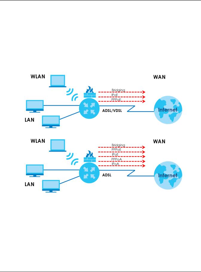
Chapter 1 Introducing the Zyxel Device
1.1.1 Internet Access
Your Zyxel Device provides shared Internet access by connecting the DSL port to the DSL or MODEM jack on a splitter or your telephone jack. You can have multiple WAN services over one ADSL or VDSL. The Zyxel Device cannot work in ADSL and VDSL mode at the same time.
Note: The ADSL and VDSL lines share the same WAN (layer-2) interfaces that you configure in the Zyxel Device. Refer to Section 6.2 on page 97 for the Network Setting > Broadband screen.
Computers can connect to the Zyxel Device’s LAN ports (or wirelessly).
Figure 1 Zyxel Device’s Internet Access Application
DSL
A
DSL
A
You can also configure IP filtering on the Zyxel Device for secure Internet access. When the IP filter is on, all incoming traffic from the Internet to your network is blocked by default unless it is initiated from your network. This means that probes from the outside to your network are not allowed, but you can safely browse the Internet and download files.
Only use firmware for your Zyxel Device’s specific model. Refer to the label on the bottom of your Zyxel Device.
1.1.2 G.fast
You can have gigabit Internet access by connecting the DSL port to the DSL or MODEM jack on a splitter or your telephone jack for G.fast.
VMG/XMG Series User’s Guide
18
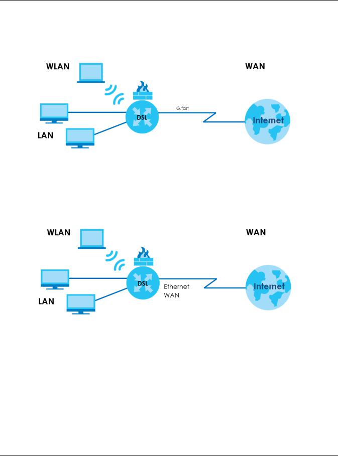
Chapter 1 Introducing the Zyxel Device
G.FAST is the acronym for Fast Access to Subscriber Terminals, and the letter G stands for the ITU-T G series of recommendations. G.fast is a technology providing gigabit speeds over traditional copper twisted-pair wires. G.fast applies Fiber-To-The-distribution point (FTTdp) structure, which reuses the deployed copper wire for the final meters.
Figure 2 Zyxel Device’s Internet Access Application: G.fast
1.1.3 Ethernet WAN
If you prefer not to use a DSL line and you have another broadband modem or router (such as ADSL) available, you can use the Ethernet WAN port and then connect it to the broadband modem or router. This way, you can access the Internet via an Ethernet connection and still use the QoS, Firewall and parental control functions on the Zyxel Device.
Figure 3 Zyxel Device’s Internet Access Application: Ethernet WAN
1.1.4 Triple Play
The ISP may provide “triple play” service to the Zyxel Device. This allows you to take advantage of “triple play” services such as Voice over IP telephony, and streaming video/audio media all at the same time, with no noticeable loss in bandwidth.
VMG/XMG Series User’s Guide
19
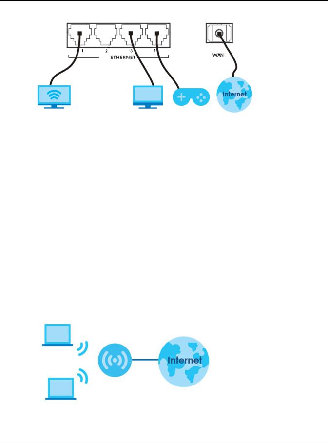
Chapter 1 Introducing the Zyxel Device
Figure 4 Triple Play Example
1.1.5 WAN Priority
The WAN connection priority is as follows:
1Ethernet WAN
2G.fast/DSL
3Cellular WAN (3G/4G)
See Section 1.1.7 on page 21 for more information about Cellular backup.
1.1.6Wireless Access
The Zyxel Device is a wireless Access Point (AP) for IEEE 802.11b/g/n/a/ac wireless clients, such as notebook computers, iPads, smartphones, etc. It allows them to connect to the Internet without having to rely on inconvenient Ethernet cables.
Your Zyxel Device supports Wi-Fi Protected Setup (WPS), which allows you to quickly set up a wireless network with strong security.
See Section 1.5.1 on page 32 for more information about how to set up a wireless network with WLAN and WPS buttons.
Figure 5 Wireless Access Example
VMG/XMG Series User’s Guide
20
![]()
Chapter 1 Introducing the Zyxel Device
1.1.7 Zyxel Device’s USB Support
The USB port of the Zyxel Device is used for cellular WAN backup, file-sharing, and media server.
Cellular WAN (3G/4G) Backup
Connect a supported cellular USB dongle with an active SIM card to the USB port. This adds a second WAN interface and allows the Zyxel Device to wirelessly access the Internet via a cellular network. The cellular WAN connection is a backup in case the DSL connection fails.
To set up a cellular connection, click Network > Broadband > Cellular Backup.
To update the supported cellular USB dongle list, download the latest WWAN package from the Zyxel website and upload it to the Zyxel Device using the Maintenance > Firmware Upgrade screen.
Figure 6 Internet Access Application: Cellular WAN
DSL
File Sharing
Use the built-in USB 3.0 port to share files on a USB memory stick or a USB hard drive (B). Use FTP to access the files on the USB device.
Figure 7 USB File Sharing Application
DSL
VMG/XMG Series User’s Guide
21
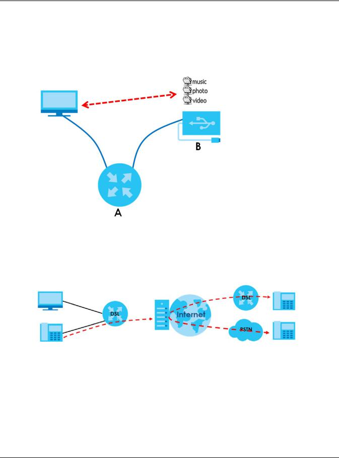
Chapter 1 Introducing the Zyxel Device
Media Server
You can also use the Zyxel Device as a media server. This lets anyone on your network play video, music, and photos from a USB device (B) connected to the Zyxel Device’s USB port (without having to copy them to another computer).
Figure 8 USB Media Server Application
DSL
1.1.8 VoIP Features
You can register up to 2 SIP (Session Initiation Protocol) accounts and use the Zyxel Device to make and receive VoIP telephone calls:
Figure 9 Zyxel Device’s VoIP Features
Calls via a VoIP service provider — the Zyxel Device sends your call to a VoIP service provider’s SIP server which forwards your calls to either VoIP or PSTN phones.
1.2 Ways to Manage the Zyxel Device
Use any of the following methods to manage the Zyxel Device.
•Web Configurator. This is recommended for everyday management of the Zyxel Device using a (supported) web browser.
•FTP. Use FTP for firmware upgrades and configuration backup/restore.
VMG/XMG Series User’s Guide
22

Chapter 1 Introducing the Zyxel Device
1.3 Good Habits for Managing the Zyxel Device
Do the following things regularly to make the Zyxel Device more secure and to manage the Zyxel Device more effectively.
•Change the password. Use a password that’s not easy to guess and that consists of different types of characters, such as numbers and letters.
•Write down the password and put it in a safe place.
•Back up the configuration (and make sure you know how to restore it). Restoring an earlier working configuration may be useful if the device becomes unstable or even crashes. If you forget your password, you will have to reset the Zyxel Device to its factory default settings. If you backed up an earlier configuration file, you would not have to totally re-configure the Zyxel Device. You could simply restore your last configuration.
1.4Hardware
Refer to the Zyxel Device’s Quick Start Guides to see the product drawings and how to make the hardware connections.
The following table describes the items on the panels.
Table 3 Panel Ports and Buttons
|
LABEL |
DESCRIPTION |
|
WLAN |
Press the WLAN button for more than one second to enable the wireless function. |
|
WPS |
Press the WPS button for more than one second to quickly set up a secure wireless connection |
|
between the device and a WPS-compatible client. |
|
|
USB |
The USB port is used for cellular WAN backup, file-sharing, media server, and print server. |
|
DSL |
Connect a RJ-11 cable to the DSL port for Internet access. |
|
PHONE1 ~ |
Connect analog phones to the phone ports to make phone calls. |
|
PHONE2 |
|
|
LAN1 ~ LAN4 |
Connect computers or other Ethernet devices to Ethernet ports for Internet access. |
|
WAN |
Connect an Ethernet cable to the Ethernet WAN port for Internet access. |
|
Power |
Connect the power cable can press the power button to start the device. |
|
Reset |
Press the button to return the Zyxel Device to the factory defaults. |
VMG/XMG Series User’s Guide
23

Chapter 1 Introducing the Zyxel Device
1.5 LEDs (Lights)
None of the LEDs are on if the Zyxel Device is not receiving power.
Table 4 VMG1312-B10D LED Descriptions
|
LED |
COLOR |
STATUS |
DESCRIPTION |
|
POWER |
Green |
On |
The Zyxel Device is receiving power and ready for use. |
|
Blinking |
The Zyxel Device is self-testing. |
||
|
Red |
On |
The Zyxel Device detected an error while self-testing, or there is a device |
|
|
malfunction. |
|||
|
Off |
The Zyxel Device is not receiving power. |
||
|
DSL |
Green |
On |
The DSL line is up. |
|
Blinking |
The Zyxel Device is initializing the DSL line. |
||
|
Off |
The DSL line is down. |
||
|
INTERNET |
Green |
On |
The Zyxel Device has an IP connection but no traffic. |
|
Your device has a WAN IP address (either static or assigned by a DHCP |
|||
|
server), PPP negotiation was successfully completed (if used) and the DSL |
|||
|
connection is up. |
|||
|
Blinking |
The Zyxel Device is sending or receiving IP traffic. |
||
|
Off |
There is no Internet connection or the gateway is in bridged mode. |
||
|
Red |
On |
The Zyxel Device attempted to make an IP connection but failed. Possible |
|
|
causes are no response from a DHCP server, no PPPoE response, PPPoE |
|||
|
authentication failed. |
|||
|
ETHERNET1~4 |
Green |
On |
The Zyxel Device has a successful 10/100 Mbps Ethernet connection with a |
|
device on the Local Area Network (LAN). |
|||
|
Blinking |
The Zyxel Device is sending or receiving data to/from the LAN at 10/100 |
||
|
Mbps. |
|||
|
Off |
The Zyxel Device does not have an Ethernet connection with the LAN. |
||
|
WLAN/WPS |
Green |
On |
The wireless network is activated. |
|
Blinking |
The Zyxel Device is communicating with wireless clients. |
||
|
Amber |
Blinking |
The Zyxel Device is setting up a WPS connection with a wireless client. |
|
|
Off |
The wireless network is not activated. |
||
|
USB |
Green |
On |
The Zyxel Device recognizes a USB connection through the USB slot. |
|
Blinking |
The Zyxel Device is sending/receiving data to/from the USB device |
||
|
connected to it. |
|||
|
Off |
The Zyxel Device does not detect a USB connection through the USB slot. |
||
|
Table 5 VMG3312-T20A LED Descriptions |
|||
|
LED |
COLOR |
STATUS |
DESCRIPTION |
|
POWER |
Green |
On |
The Zyxel Device is receiving power and ready for use. |
|
Blinking |
The Zyxel Device is self-testing. |
||
|
Red |
On |
The Zyxel Device detected an error while self-testing, or there is a device |
|
|
malfunction. |
|||
|
Off |
The Zyxel Device is not receiving power. |
||
VMG/XMG Series User’s Guide
24

Chapter 1 Introducing the Zyxel Device
Table 5 VMG3312-T20A LED Descriptions (continued)
|
LED |
COLOR |
STATUS |
DESCRIPTION |
|
ETHERNET1~4 |
Green |
On |
The Zyxel Device has a successful 10/100 Mbps Ethernet connection with a |
|
device on the Local Area Network (LAN). |
|||
|
Blinking |
The Zyxel Device is sending or receiving data to/from the LAN at 10/100 |
||
|
Mbps. |
|||
|
Off |
The Zyxel Device does not have an Ethernet connection with the LAN. |
||
|
WLAN |
Green |
On |
The wireless network is activated. |
|
Blinking |
The Zyxel Device is communicating with wireless clients. |
||
|
WPS |
Amber |
Blinking |
The Zyxel Device is setting up a WPS connection with a wireless client. |
|
Off |
The wireless network is not activated. |
||
|
DSL |
Green |
On |
The VDSL line is up. |
|
Blinking |
The Zyxel Device is initializing the VDSL line. |
||
|
Off |
The DSL line is down. |
||
|
Orange |
On |
The ADSL line is up. |
|
|
Slow |
The Zyxel Device is detecting carrier signals. |
||
|
Blinking |
|||
|
Fast |
The Zyxel Device is initializing the VDSL line. |
||
|
Blinking |
|||
|
WAN |
Green |
On |
The Zyxel Device has a successful 10/100/1000 Mbps Ethernet connection |
|
on the WAN. |
|||
|
Blinking |
The Zyxel Device is sending or receiving data to/from the WAN at 10/100/ |
||
|
1000 Mbps. |
|||
|
Off |
The Zyxel Device does not have an Ethernet connection with the WAN. |
||
|
INTERNET |
Green |
On |
The Zyxel Device has an IP connection but no traffic. |
|
Your device has a WAN IP address (either static or assigned by a DHCP |
|||
|
server). PPP negotiation was successfully completed (if used) and the DSL |
|||
|
connection is up. |
|||
|
Blinking |
The VMG is sending or receiving IP traffic. |
||
|
Off |
There is no Internet connection or the gateway is in bridged mode. |
||
|
Red |
On |
The VMG attempted to make an IP connection but failed. Possible causes |
|
|
are no response from a DHCP server, no PPPoE response, PPPoE |
|||
|
authentication failed. |
|||
|
USB |
Green |
On |
The Zyxel Device recognizes a USB connection through the USB slot. |
|
Blinking |
The Zyxel Device is sending/receiving data to/from the USB device |
||
|
connected to it. |
|||
|
Off |
The Zyxel Device does not detect a USB connection through the USB slot. |
||
|
Table 6 VMG3625-T20A LED Descriptions |
|||
|
LED |
COLOR |
STATUS |
DESCRIPTION |
|
POWER |
Green |
On |
The Zyxel Device is receiving power and ready for use. |
|
Blinking |
The Zyxel Device is self-testing. |
||
|
Red |
On |
The Zyxel Device detected an error while self-testing, or there is a device |
|
|
malfunction. |
|||
|
Blinking |
The Zyxel Device is upgrading firmware. |
||
|
Off |
The Zyxel Device is not receiving power. |
||
VMG/XMG Series User’s Guide
25

Chapter 1 Introducing the Zyxel Device
Table 6 VMG3625-T20A LED Descriptions (continued)
|
LED |
COLOR |
STATUS |
DESCRIPTION |
|
DSL |
Green |
On |
The VDSL line is up. |
|
Blinking |
The Zyxel Device is initializing the VDSL line. |
||
|
Off |
The DSL line is down. |
||
|
Orange |
On |
The ADSL line is up. |
|
|
Slow |
The Zyxel Device is detecting carrier signals. |
||
|
Blinking |
|||
|
Fast |
The Zyxel Device is initializing the ADSL line. |
||
|
Blinking |
|||
|
INTERNET |
Green |
On |
The Zyxel Device has an IP connection but no traffic. |
|
Your device has a WAN IP address (either static or assigned by a DHCP |
|||
|
server). PPP negotiation was successfully completed (if used) and the DSL |
|||
|
connection is up. |
|||
|
Blinking |
The VMG is sending or receiving IP traffic. |
||
|
Off |
There is no Internet connection or the gateway is in bridged mode. |
||
|
Red |
On |
The VMG attempted to make an IP connection but failed. Possible causes |
|
|
are no response from a DHCP server, no PPPoE response, PPPoE |
|||
|
authentication failed. |
|||
|
WAN |
Green |
On |
The Zyxel Device has a successful 10/100/1000 Mbps Ethernet connection |
|
on the WAN. |
|||
|
Blinking |
The Zyxel Device is sending or receiving data to/from the WAN at 10/100/ |
||
|
1000 Mbps. |
|||
|
Off |
The Zyxel Device does not have an Ethernet connection with the WAN. |
||
|
ETHERNET1~4 |
Green |
On |
The Zyxel Device has a successful 10/100/1000 Mbps Ethernet connection |
|
with a device on the Local Area Network (LAN). |
|||
|
Blinking |
The Zyxel Device is sending or receiving data to/from the LAN at 10/100 |
||
|
Mbps. |
|||
|
Off |
The Zyxel Device does not have an Ethernet connection with the LAN. |
||
|
WLAN |
Green |
On |
The wireless network is activated. |
|
Blinking |
The Zyxel Device is communicating with wireless clients. |
||
|
Off |
The wireless network is not activated or down. |
||
|
Orange |
Blinking |
The Zyxel Device is setting up a WPS connection with a 2.4 GHz or 5 GHz |
|
|
wireless client. |
|||
|
USB |
Green |
On |
The Zyxel Device recognizes a USB connection through the USB slot. |
|
Blinking |
The Zyxel Device is sending/receiving data to/from the USB device |
||
|
connected to it. |
|||
|
Off |
The Zyxel Device does not detect a USB connection through the USB slot. |
||
|
Table 7 VMG3925-B10B LED Descriptions |
|||
|
LED |
COLOR |
STATUS |
DESCRIPTION |
|
Power |
Green |
On |
The Zyxel Device is receiving power and ready for use. |
|
Blinking |
The Zyxel Device is self-testing. |
||
|
Red |
On |
The Zyxel Device detected an error while self-testing, or there is a device |
|
|
malfunction. |
|||
|
Off |
The Zyxel Device is not receiving power. |
||
VMG/XMG Series User’s Guide
26

Chapter 1 Introducing the Zyxel Device
Table 7 VMG3925-B10B LED Descriptions (continued)
|
LED |
COLOR |
STATUS |
DESCRIPTION |
|
DSL |
Green |
On |
The VDSL line is up. |
|
Blinking |
The Zyxel Device is initializing the VDSL line. |
||
|
Orange |
On |
The ADSL line is up. |
|
|
Blinking |
The Zyxel Device is initializing the ADSL line. |
||
|
Off |
The DSL line is down. |
||
|
Internet |
Green |
On |
The Zyxel Device has an IP connection but no traffic. |
|
Your device has a WAN IP address (either static or assigned by a DHCP |
|||
|
server), PPP negotiation was successfully completed (if used) and the DSL |
|||
|
connection is up. |
|||
|
Blinking |
The Zyxel Device is sending or receiving IP traffic. |
||
|
Off |
There is no Internet connection or the gateway is in bridged mode. |
||
|
Red |
On |
The Zyxel Device attempted to make an IP connection but failed. Possible |
|
|
causes are no response from a DHCP server, no PPPoE response, PPPoE |
|||
|
authentication failed. |
|||
|
Ethernet |
Green |
On |
The Zyxel Device has a successful 1000 Mbps Ethernet connection on the |
|
WAN |
WAN. |
||
|
Blinking |
The Zyxel Device is sending or receiving data to/from the WAN at 1000 |
||
|
Mbps. |
|||
|
Orange |
On |
The Zyxel Device has a successful 10/100 Mbps Ethernet connection on the |
|
|
WAN. |
|||
|
Blinking |
The Zyxel Device is sending or receiving data to/from the WAN at 10/100 |
||
|
Mbps. |
|||
|
Off |
There is no Ethernet connection on the WAN. |
||
|
LAN1~4 |
Green |
On |
The Zyxel Device has a successful 1000 Mbps Ethernet connection with a |
|
device on the Local Area Network (LAN). |
|||
|
Blinking |
The Zyxel Device is sending or receiving data to/from the LAN at 1000 Mbps. |
||
|
Off |
The Zyxel Device does not have an Ethernet connection with the LAN. |
||
|
2.4G WLAN/ |
Green |
On |
The 2.4 GHz wireless network is activated. |
|
WPS |
|||
|
Blinking |
The Zyxel Device is communicating with 2.4 GHz wireless clients. |
||
|
Amber |
Blinking |
The Zyxel Device is setting up a WPS connection with a 2.4 GHz wireless |
|
|
client. |
|||
|
Off |
The 2.4 GHz wireless network is not activated. |
||
|
5G WLAN/ |
Green |
On |
The 5 GHz wireless network is activated. |
|
WPS |
|||
|
Blinking |
The Zyxel Device is communicating with 5 GHz wireless clients. |
||
|
Amber |
Blinking |
The Zyxel Device is setting up a WPS connection with a 5 GHz wireless client. |
|
|
Off |
The 5 GHz wireless network is not activated. |
||
|
USB1 |
Green |
On |
The Zyxel Device recognizes a USB connection through the USB1 slot. |
|
Blinking |
The Zyxel Device is sending/receiving data to /from the USB device |
||
|
connected to it. |
|||
|
Off |
The Zyxel Device does not detect a USB connection through the USB1 slot. |
||
VMG/XMG Series User’s Guide
27

Chapter 1 Introducing the Zyxel Device
Table 8 VMG3925-B10C LED Descriptions
|
LED |
COLOR |
STATUS |
DESCRIPTION |
|
Power |
Green |
On |
The Zyxel Device is receiving power and ready for use. |
|
Blinking |
The Zyxel Device is self-testing. |
||
|
Red |
On |
The Zyxel Device detected an error while self-testing, or there is a device |
|
|
malfunction. |
|||
|
Blinking |
The Zyxel Device is uploading firmware. |
||
|
Off |
The Zyxel Device is not receiving power. |
||
|
DSL |
Green |
On |
The VDSL line is up. |
|
Blinking |
The Zyxel Device is looking for a VDSL line. |
||
|
(slow) |
|||
|
Blinking |
The Zyxel Device is initializing the VDSL line. |
||
|
(fast) |
|||
|
Amber |
On |
The ADSL line is up. |
|
|
Blinking |
The Zyxel Device is looking for an ADSL line. |
||
|
(slow) |
|||
|
Blinking |
The Zyxel Device is initializing the ADSL line. |
||
|
(fast) |
|||
|
Off |
The DSL line is down. |
||
|
Internet |
Green |
On |
The Zyxel Device has an IP connection but no traffic. |
|
Your device has a WAN IP address (either static or assigned by a DHCP |
|||
|
server), PPP negotiation was successfully completed (if used) and the DSL |
|||
|
connection is up. |
|||
|
Blinking |
The Zyxel Device is sending or receiving IP traffic. |
||
|
Off |
There is no Internet connection or the gateway is in bridged mode. |
||
|
Red |
On |
The Zyxel Device attempted to make an IP connection but failed. Possible |
|
|
causes are no response from a DHCP server, no PPPoE response, PPPoE |
|||
|
authentication failed. |
|||
|
WAN |
Green |
On |
The Zyxel Device has a successful 10/100/1000 Mbps Ethernet connection |
|
on the WAN. |
|||
|
Blinking |
The Zyxel Device is sending or receiving data to/from the WAN at 10/100/ |
||
|
1000 Mbps. |
|||
|
Off |
There is no Ethernet connection on the WAN. |
||
|
LAN1~4 |
Green |
On |
The Zyxel Device has a successful 10/100/1000 Mbps Ethernet connection |
|
with a device on the Local Area Network (LAN). |
|||
|
Blinking |
The Zyxel Device is sending or receiving data to/from the LAN at 10/100/ |
||
|
1000 Mbps. |
|||
|
Off |
The Zyxel Device does not have an Ethernet connection with the LAN. |
||
|
2.4G WLAN/ |
Green |
On |
The 2.4 GHz wireless network is activated. |
|
WPS |
|||
|
Blinking |
The Zyxel Device is communicating with 2.4 GHz wireless clients. |
||
|
Amber |
Blinking |
The Zyxel Device is setting up a WPS connection with a 2.4 GHz wireless |
|
|
client. |
|||
|
Off |
The 2.4 GHz wireless network is not activated. |
||
|
5G WLAN/ |
Green |
On |
The 5 GHz wireless network is activated. |
|
WPS |
|||
|
Blinking |
The Zyxel Device is communicating with 5 GHz wireless clients. |
||
|
Amber |
Blinking |
The Zyxel Device is setting up a WPS connection with a 5 GHz wireless client. |
|
|
Off |
The 5 GHz wireless network is not activated. |
||
VMG/XMG Series User’s Guide
28

Chapter 1 Introducing the Zyxel Device
Table 8 VMG3925-B10C LED Descriptions (continued)
|
LED |
COLOR |
STATUS |
DESCRIPTION |
|
|
USB |
Green |
On |
The Zyxel Device recognizes a USB connection through the USB1 slot. |
|
|
Blinking |
The Zyxel Device is sending/receiving data to /from the USB device |
|||
|
connected to it. |
||||
|
Off |
The Zyxel Device does not detect a USB connection through the USB1 slot. |
|||
|
Table 9 XMG3927-B50A/VMG3927-BX0A/VMG8825-BX0A LED Descriptions |
||||
|
LED |
COLOR |
STATUS |
DESCRIPTION |
|
|
POWER |
Blue |
On |
The Zyxel Device is receiving power and ready for use. |
|
|
Blinking |
The Zyxel Device is self-testing. |
|||
|
Red |
On |
The Zyxel Device detected an error while self-testing, or there is a device |
||
|
malfunction. |
||||
|
Blinking |
The Zyxel Device is uploading firmware. |
|||
|
Off |
The Zyxel Device is not receiving power. |
|||
|
WAN |
Blue |
On |
One of the following connections is up. |
|
|
• |
ADSL |
|||
|
• |
G.fast |
|||
|
• |
VDSL |
|||
|
• Ethernet connection on the WAN. |
||||
|
Blinking |
The ADSL/G.fast/VDSL link is down, and the Zyxel Device is looking for an |
|||
|
(slow) |
ADSL/G.fast/VDSL link. |
|||
|
Blinking |
The Zyxel Device is initializing the ADSL/G.fast/VDSL link. |
|||
|
(fast) |
||||
|
Off |
There is no Ethernet connection on the WAN. |
|||
|
INTERNET |
Blue |
On |
Your device has a WAN IP address (either static or assigned by a DHCP |
|
|
server), PPP negotiation was successfully completed (if used) and the DSL |
||||
|
connection is up. |
||||
|
Blinking |
The Zyxel Device is sending or receiving IP traffic. |
|||
|
Off |
There is no Internet connection or the gateway is in bridged mode. |
|||
|
Red |
On |
The Zyxel Device attempted to make an IP connection but failed. Possible |
||
|
causes are no response from a DHCP server, no PPPoE response, PPPoE |
||||
|
authentication failed. |
||||
|
ETHERNET1~4 |
Blue |
On |
The Zyxel Device has a successful 10/100/1000 Mbps Ethernet connection |
|
|
with a device on the Local Area Network (LAN). |
||||
|
Blinking |
The Zyxel Device is sending or receiving data to/from the LAN at 10/100/ |
|||
|
1000 Mbps. |
||||
|
Off |
The Zyxel Device does not have an Ethernet connection with the LAN. |
|||
|
2.4G WLAN/ |
Blue |
On |
The 2.4 GHz wireless network is activated. |
|
|
WPS |
||||
|
Blinking |
The Zyxel Device is communicating with 2.4 GHz wireless clients. |
|||
|
Amber |
Blinking |
The Zyxel Device is setting up a WPS connection with a 2.4 GHz wireless |
||
|
client. |
||||
|
Off |
The 2.4 GHz wireless network is not activated. |
|||
|
5G WLAN/ |
Blue |
On |
The 5 GHz wireless network is activated. |
|
|
WPS |
||||
|
Blinking |
The Zyxel Device is communicating with 5 GHz wireless clients. |
|||
|
Amber |
Blinking |
The Zyxel Device is setting up a WPS connection with a 5 GHz wireless client. |
||
|
Off |
The 5 GHz wireless network is not activated. |
|||
VMG/XMG Series User’s Guide
29

Chapter 1 Introducing the Zyxel Device
Table 10 VMG8823-BX0B LED Descriptions
|
LED |
COLOR |
STATUS |
DESCRIPTION |
|
Power |
Green |
On |
The Zyxel Device is receiving power and ready for use. |
|
Blinking |
The Zyxel Device is self-testing. |
||
|
Red |
On |
The Zyxel Device detected an error while self-testing, or there is a device |
|
|
malfunction. |
|||
|
Blinking |
The VMG is upgrading firmware. |
||
|
Off |
The Zyxel Device is not receiving power. |
||
|
DSL |
Green |
On |
The VDSL line is up. |
|
Slow |
The Zyxel Device is detecting carrier signals. |
||
|
Blinking |
|||
|
Fast |
The Zyxel Device is initializing the VDSL line. |
||
|
Blinking |
|||
|
Orange |
On |
The ADSL line is up. |
|
|
Slow |
The Zyxel Device is detecting carrier signals. |
||
|
Blinking |
|||
|
Fast |
The Zyxel Device is initializing the ADSL line. |
||
|
Blinking |
|||
|
Off |
The DSL line is down. |
||
|
Internet |
Green |
On |
The Zyxel Device has an IP connection but no traffic. |
|
Your device has a WAN IP address (either static or assigned by a DHCP |
|||
|
server), PPP negotiation was successfully completed (if used) and the DSL |
|||
|
connection is up. |
|||
|
Blinking |
The Zyxel Device is sending or receiving IP traffic. |
||
|
Off |
There is no Internet connection or the gateway is in bridged mode. |
||
|
Red |
On |
The Zyxel Device attempted to make an IP connection but failed. Possible |
|
|
causes are no response from a DHCP server, no PPPoE response, PPPoE |
|||
|
authentication failed. |
|||
|
WAN |
Green |
On |
The Zyxel Device has a successful 10/100/1000 Mbps Ethernet connection |
|
on the WAN. |
|||
|
Blinking |
The Zyxel Device is sending or receiving data to/from the WAN at 10/100/ |
||
|
1000 Mbps. |
|||
|
Off |
There is no Ethernet connection on the WAN. |
||
|
LAN1~4 |
Green |
On |
The Zyxel Device has a successful 10/100/1000 Mbps Ethernet connection |
|
with a device on the Local Area Network (LAN). |
|||
|
Blinking |
The Zyxel Device is sending or receiving data to/from the LAN at 10/100/ |
||
|
1000 Mbps. |
|||
|
Off |
The Zyxel Device does not have an Ethernet connection with the LAN. |
||
|
WLAN/WPS |
Green |
On |
The 2.4 GHz or 5 GHz wireless network is activated. |
|
Blinking |
The Zyxel Device is communicating with 2.4 GHz or 5 GHz wireless clients. |
||
|
Amber |
Blinking |
The Zyxel Device is setting up a WPS connection with a 2.4 GHz or 5 GHz |
|
|
wireless client. |
|||
|
Off |
The 2.4 GHz or 5 GHz wireless network is not activated. |
||
VMG/XMG Series User’s Guide
30
![]()
Chapter 1 Introducing the Zyxel Device
Table 10 VMG8823-BX0B LED Descriptions (continued)
|
LED |
COLOR |
STATUS |
DESCRIPTION |
|
Phone1, |
Green |
On |
A SIP account is registered for the phone port. |
|
Phone2 |
|||
|
Blinking |
A telephone connected to the phone port has its receiver off of the hook or |
||
|
there is an incoming call. |
|||
|
Orange |
On |
A SIP account is registered for the phone port and there is a voice message |
|
|
in the corresponding SIP account. |
|||
|
Blinking |
A telephone connected to the phone port has its receiver off of the hook |
||
|
and there is a voice message in the corresponding SIP account. |
|||
|
Off |
The phone port does not have a SIP account registered. |
||
|
USB |
Green |
On |
The Zyxel Device recognizes a USB connection through the USB slot. |
|
Blinking |
The Zyxel Device is sending/receiving data to /from the USB device |
||
|
connected to it. |
|||
|
Off |
The Zyxel Device does not detect a USB connection through the USB slot. |
||
|
Table 11 VMG8924-B10D LED Descriptions |
|||
|
LED |
COLOR |
STATUS |
DESCRIPTION |
|
Power |
Green |
On |
The Zyxel Device is receiving power and ready for use. |
|
Blinking |
The Zyxel Device is self-testing. |
||
|
Red |
On |
The Zyxel Device detected an error while self-testing, or there is a device |
|
|
malfunction. |
|||
|
Blinking |
The VMG is upgrading firmware. |
||
|
Off |
The Zyxel Device is not receiving power. |
||
|
DSL |
Green |
On |
The VDSL line is up. |
|
Slow |
The Zyxel Device is detecting carrier signals. |
||
|
Blinking |
|||
|
Fast |
The Zyxel Device is initializing the VDSL line. |
||
|
Blinking |
|||
|
Orange |
On |
The ADSL line is up. |
|
|
Slow |
The Zyxel Device is detecting carrier signals. |
||
|
Blinking |
|||
|
Fast |
The Zyxel Device is initializing the ADSL line. |
||
|
Blinking |
|||
|
Off |
The DSL line is down. |
||
|
Internet |
Green |
On |
The Zyxel Device has an IP connection but no traffic. |
|
Your device has a WAN IP address (either static or assigned by a DHCP |
|||
|
server), PPP negotiation was successfully completed (if used) and the DSL |
|||
|
connection is up. |
|||
|
Blinking |
The Zyxel Device is sending or receiving IP traffic. |
||
|
Off |
There is no Internet connection or the gateway is in bridged mode. |
||
|
Red |
On |
The Zyxel Device attempted to make an IP connection but failed. Possible |
|
|
causes are no response from a DHCP server, no PPPoE response, PPPoE |
|||
|
authentication failed. |
|||
|
WAN |
Green |
On |
The Zyxel Device has a successful 10/100/1000 Mbps Ethernet connection |
|
on the WAN. |
|||
|
Blinking |
The Zyxel Device is sending or receiving data to/from the WAN at 10/100/ |
||
|
1000 Mbps. |
|||
|
Off |
There is no Ethernet connection on the WAN. |
||
VMG/XMG Series User’s Guide
31

Chapter 1 Introducing the Zyxel Device
Table 11 VMG8924-B10D LED Descriptions (continued)
|
LED |
COLOR |
STATUS |
DESCRIPTION |
|
LAN1~4 |
Green |
On |
The Zyxel Device has a successful 10/100/1000 Mbps Ethernet connection |
|
with a device on the Local Area Network (LAN). |
|||
|
Blinking |
The Zyxel Device is sending or receiving data to/from the LAN at 10/100/ |
||
|
1000 Mbps. |
|||
|
Off |
The Zyxel Device does not have an Ethernet connection with the LAN. |
||
|
WLAN/WPS |
Green |
On |
The 2.4 GHz or 5 GHz wireless network is activated. |
|
Blinking |
The Zyxel Device is communicating with 2.4 GHz or 5 GHz wireless clients. |
||
|
Orange |
Blinking |
The Zyxel Device is setting up a WPS connection with a 2.4 GHz or 5 GHz |
|
|
wireless client. |
|||
|
Off |
The 2.4 GHz or 5 GHz wireless network is not activated. |
||
|
Phone1, |
Green |
On |
A SIP account is registered for the phone port. |
|
Phone2 |
|||
|
Blinking |
A telephone connected to the phone port has its receiver off of the hook or |
||
|
there is an incoming call. |
|||
|
Orange |
On |
A SIP account is registered for the phone port and there is a voice message |
|
|
in the corresponding SIP account. |
|||
|
Blinking |
A telephone connected to the phone port has its receiver off of the hook |
||
|
and there is a voice message in the corresponding SIP account. |
|||
|
Off |
The phone port does not have a SIP account registered. |
||
|
USB |
Green |
On |
The Zyxel Device recognizes a USB connection through the USB slot. |
|
Blinking |
The Zyxel Device is sending/receiving data to /from the USB device |
||
|
connected to it. |
|||
|
Off |
The Zyxel Device does not detect a USB connection through the USB slot. |
||
1.5.1 Using the WLAN and WPS Buttons
If the wireless network is turned off, press the WLAN button. Check the WLAN/WPS LED on the front panel to see if the wireless network is active.
You can also use the WPS button to quickly set up a secure wireless connection between the Zyxel Device and a WPS-compatible client by adding one device at a time.
To activate WPS:
1Make sure the POWER LED is on and not blinking.
2Press the WPS button and release it.
3Press the WPS button on another WPS-enabled device within range of the Zyxel Device. The WLAN/WPS LED flashes amber while the Zyxel Device sets up a WPS connection with the other wireless device.
4Once the connection is successfully made, the WLAN/WPS LED shines blue or green.
Note: If your Zyxel Device supports both 2.4 GHz and 5 GHz wireless networks, the connection to the 2.4 GHz wireless network has priority.
To turn off the wireless network, press the WLAN button. The WLAN/WPS LED turns off when the wireless network is off.
VMG/XMG Series User’s Guide
32

Chapter 1 Introducing the Zyxel Device
See the following table to see how long you need to press the WLAN and WPS buttons on the Zyxel Device.
Table 12 WLAN and WPA Buttons
|
MODEL |
WLAN BUTTON |
WPS BUTTON |
|
VMG1312-B10D |
One second |
Two seconds |
|
VMG3312-T20A |
More than two seconds |
More than five seconds |
|
VMG3625-T20A |
More than two seconds |
More than five seconds |
|
VMG3925-B10B |
Two seconds |
Two seconds |
|
VMG3925-B10C |
More than two seconds |
More than five seconds |
|
XMG3927-B50A |
More than one second |
More than one second |
|
VMG3927-Bx0A |
More than one second |
More than one second |
|
VMG8823-Bx0B |
More than two seconds |
More than five seconds |
|
VMG8825-Bx0A |
More than one second |
More than one second |
|
VMG8924-B10D |
More than two seconds |
More than five seconds |
1.5.2 The RESET Button
If you forget your password or cannot access the Web Configurator, you will need to use the RESET button to reload the factory-default configuration file. This means that you will lose all configurations that you had previously. The password will be reset to the factory default (see the device label), and the LAN IP address will be “192.168.1.1”.
1Make sure the POWER LED is on (not blinking).
2To set the device back to the factory default settings, press the RESET button or until the POWER LED begins to blink and then release it. When the POWER LED begins to blink, the defaults have been restored and the device restarts.
See the following table to see how long you need to press the RESET button on the Zyxel Device. Table 13 RESET Button
|
MODEL |
RESET BUTTON |
|
VMG1312-B10D |
One second |
|
VMG3312-T20A |
Five seconds |
|
VMG3625-T20A |
Five seconds |
|
VMG3925-B10B |
Ten seconds |
|
VMG3925-B10C |
More than five seconds |
|
XMG3927-B50A |
More than five seconds |
|
VMG3927-Bx0A |
More than five seconds |
|
VMG8823-Bx0B |
Five seconds |
|
VMG8825-Bx0A |
More than five seconds |
|
VMG8924-B10D |
Five seconds |
VMG/XMG Series User’s Guide
33

CHAPTER 2
The Web Configurator
2.1 Overview
The web configurator is an HTML-based management interface that allows easy Zyxel Device setup and management via Internet browser. Use Internet Explorer 8.0 and later versions or Mozilla Firefox 3 and later versions or Safari 2.0 and later versions. The recommended screen resolution is 1024 by 768 pixels.
In order to use the web configurator you need to allow:
•Web browser pop-up windows from your Zyxel Device. Web pop-up blocking is enabled by default in Windows XP SP (Service Pack) 2.
•JavaScript (enabled by default).
•Java permissions (enabled by default).
2.1.1Accessing the Web Configurator
1Make sure your Zyxel Device hardware is properly connected (refer to the Quick Start Guide).
2Launch your web browser. If the Zyxel Device does not automatically re-direct you to the login screen, go to http://192.168.1.1.
3A password screen displays. Select the language you prefer.
4To access the administrative web configurator and manage the Zyxel Device, type the default username admin and the randomly assigned default password (see the device label) in the password screen and click Login. If you have changed the password, enter your password and click Login.
Figure 10 Password Screen
VMG/XMG Series User’s Guide
34

Chapter 2 The Web Configurator
5The following screen displays when you log into the web configurator for the first time. Enter a new password, retype it to confirm, and click Change password. If you prefer to use the default password, click Skip.
Figure 11 Change Password Screen
6The Wizard screen displays when you log into the web configurator for the first time. Use the Wizard screens to configure the Zyxel Device’s time zone, basic Internet access, and wireless settings. See Chapter 3 on page 42 for more information about the Wizard screens.
7The Connection Status page appears. Use this screen to configure basic Internet access, wireless settings, and parental control settings.
Figure 12 Connection Status
VMG/XMG Series User’s Guide
35

Chapter 2 The Web Configurator
2.2 Web Configurator Layout
Figure 13 Screen Layout
A
C
B
As illustrated above, the main screen is divided into these parts:
•A — Settings Icon (Navigation Panel & Side Bar)
•B — Widget Icon
•C — Main Window
2.2.1Settings Icon
Click this icon ( ) to see the side bar and navigation panel.
2.2.1.1 Side Bar
The side bar provides some icons on the right hand side.
VMG/XMG Series User’s Guide
36

Chapter 2 The Web Configurator
The icons provide the following functions.
Table 14 Web Configurator Icons in the Title Bar
ICON DESCRIPTION
Wizard: Click this icon to open screens where you can configure the Zyxel Device’s time zone
Internet access, and wireless settings. See Chapter 3 on page 42 for more information about the
Wizard screens.
Theme: Click this icon to select a color that you prefer and apply it to the web configurator.Network Temporarily Disconnected
Language: Select the language you prefer.
Restart: Click this icon to reboot the Zyxel Device without turning the power off.
Logout: Click this icon to log out of the web configurator.
2.2.1.2 Navigation Panel
Use the menu items on the navigation panel to open screens to configure Zyxel Device features. The following tables describe each menu item.
Note: The menu items on the navigation panel vary among the models. See Section 1.1 on page 17 for more information about the feature differences of the Zyxel Device .
Table 15 Navigation Panel Summary
|
LINK |
TAB |
FUNCTION |
|
Connection Status |
Use this screen to configure basic Internet access, wireless settings, and |
|
|
parental control settings. This screen also shows the network status of the |
||
|
Zyxel Device and computers/devices connected to it. |
||
|
Network Setting |
||
|
Broadband |
Broadband |
Use this screen to view and configure ISP parameters, WAN IP address |
|
assignment, and other advanced properties. You can also add new |
||
|
WAN connections. |
||
|
Cellular Backup |
Use this screen to configure 3G WAN connection. |
|
|
Advanced |
Use this screen to enable or disable PTM over ADSL, Annex M/Annex J, |
|
|
and DSL PhyR functions. |
||
VMG/XMG Series User’s Guide
37

Chapter 2 The Web Configurator
Table 15 Navigation Panel Summary (continued)
|
LINK |
TAB |
FUNCTION |
|
Wireless |
General |
Use this screen to configure the wireless LAN settings and WLAN |
|
authentication/security settings. |
||
|
Guest/More AP |
Use this screen to configure multiple BSSs on the Zyxel Device. |
|
|
MAC |
Use this screen to block or allow wireless traffic from wireless devices of |
|
|
Authentication |
certain SSIDs and MAC addresses to the Zyxel Device. |
|
|
WPS |
Use this screen to configure and view your WPS (Wi-Fi Protected Setup) |
|
|
settings. |
||
|
WMM |
Use this screen to enable or disable Wi-Fi MultiMedia (WMM). |
|
|
Others |
Use this screen to configure advanced wireless settings. |
|
|
Channel Status |
Use this screen to scan wireless LAN channel noises and view the results. |
|
|
MESH |
Use this screen to enable or disable Zyxel Mesh (Multy Pro). |
|
|
Home |
LAN Setup |
Use this screen to configure LAN TCP/IP settings, and other advanced |
|
Networking |
properties. |
|
|
Static DHCP |
Use this screen to assign specific IP addresses to individual MAC |
|
|
addresses. |
||
|
UPnP |
Use this screen to turn UPnP and UPnP NAT-T on or off. |
|
|
Additional |
Use this screen to configure IP alias and public static IP. |
|
|
Subnet |
||
|
STB Vendor ID |
Use this screen to configure the Vendor IDs of the connected Set Top Box |
|
|
(STB) devices, which have the Zyxel Device automatically create static |
||
|
DHCP entries for the STB devices when they request IP addresses. |
||
|
Wake on LAN |
Use this screen to remotely turn on a device on the local network. |
|
|
TFTP Server Name |
Use DHCP option 66 to identify a TFTP server name. |
|
|
Routing |
Static Route |
Use this screen to view and set up static routes on the Zyxel Device. |
|
DNS Route |
Use this screen to forward DNS queries for certain domain names through |
|
|
a specific WAN interface to its DNS server(s). |
||
|
Policy Route |
Use this screen to configure policy routing on the Zyxel Device. |
|
|
RIP |
Use this screen to configure Routing Information Protocol to exchange |
|
|
routing information with other routers. |
||
|
QoS |
General |
Use this screen to enable QoS and traffic prioritizing. You can also |
|
configure the QoS rules and actions. |
||
|
Queue Setup |
Use this screen to configure QoS queues. |
|
|
Classification |
Use this screen to define a classifier. |
|
|
Setup |
||
|
Shaper Setup |
Use this screen to limit outgoing traffic rate on the selected interface. |
|
|
Policer Setup |
Use this screen to configure QoS policers. |
|
|
NAT |
Port Forwarding |
Use this screen to make your local servers visible to the outside world. |
|
Port Triggering |
Use this screen to change your Zyxel Device’s port triggering settings. |
|
|
DMZ |
Use this screen to configure a default server which receives packets from |
|
|
ports that are not specified in the Port Forwarding screen. |
||
|
ALG |
Use this screen to enable or disable SIP ALG. |
|
|
Address Mapping |
Use this screen to change your Zyxel Device’s address mapping settings. |
|
|
Sessions |
Use this screen to configure the maximum number of NAT sessions each |
|
|
client host is allowed to have through the Zyxel Device. |
||
VMG/XMG Series User’s Guide
38

Chapter 2 The Web Configurator
Table 15 Navigation Panel Summary (continued)
|
LINK |
TAB |
FUNCTION |
|
DNS |
DNS Entry |
Use this screen to view and configure DNS routes. |
|
Dynamic DNS |
Use this screen to allow a static hostname alias for a dynamic IP address. |
|
|
IGMP/MLD |
IGMP/MLD |
Use this screen to configure multicast settings (IGMP for IPv4 and MLD for |
|
IPv6 multicast groups) on the WAN. |
||
|
Vlan Group |
Vlan Group |
Use this screen to group and tag VLAN IDs to outgoing traffic from the |
|
specified interface. |
||
|
Interface |
Interface |
Use this screen to map a port to a PVC or bridge group. |
|
Grouping |
Grouping |
|
|
USB Service |
File Sharing |
Use this screen to enable file sharing via the Zyxel Device. |
|
Media Server |
Use this screen to use the Zyxel Device as a media server. |
|
|
Home |
Home |
Use this screen to enable or disable Wi-Fi auto-configuration. |
|
Connectivity |
Connectivity |
|
|
Security |
||
|
Firewall |
General |
Use this screen to configure the security level of your firewall. |
|
Protocol |
Use this screen to add Internet services and configure firewall rules. |
|
|
Access Control |
Use this screen to enable specific traffic directions for network services. |
|
|
Dos |
Use this screen to activate protection against Denial of Service (DoS) |
|
|
attacks. |
||
|
MAC Filter |
MAC Filter |
Use this screen to block or allow traffic from devices of certain MAC |
|
addresses to the Zyxel Device. |
||
|
Parental |
Parental Control |
Use this screen to block web sites with the specific URL. |
|
Control |
||
|
Scheduler Rule |
Scheduler Rule |
Use this screen to configure the days and times when a configured |
|
restriction (such as parental control) is enforced. |
||
|
Certificates |
Local Certificates |
Use this screen to view a summary list of certificates and manage |
|
certificates and certification requests. |
||
|
Trusted CA |
Use this screen to view and manage the list of the trusted CAs. |
|
|
VoIP |
||
|
SIP |
SIP Account |
Use this screen to set up information about your SIP account and |
|
configure audio settings such as volume levels for the phones |
||
|
connected to the Zyxel Device. |
||
|
SIP Service |
Use this screen to configure the SIP server information, QoS for VoIP calls, |
|
|
Provider |
the numbers for certain phone functions, and dialing plan. |
|
|
Phone |
Phone |
Use this screen to select your location and a call service mode. |
|
Region |
Use this screen to select your location and a call service mode. |
|
|
Call Rule |
Call Rule |
Use this screen to configure speed dial for SIP phone numbers that you |
|
call often. |
||
|
Call History |
Call History |
Use this screen to view a call history list. |
|
Call Summary |
Use this screen to view the summary of received, dialed and missed calls. |
|
|
System Monitor |
||
VMG/XMG Series User’s Guide
39

Chapter 2 The Web Configurator
Table 15 Navigation Panel Summary (continued)
|
LINK |
TAB |
FUNCTION |
||
|
Log |
System Log |
Use this screen to view the status of events that occurred to the Zyxel |
||
|
Device. You can export or e-mail the logs. |
||||
|
Security Log |
Use this screen to view all security related events. You can select level |
|||
|
and category of the security events in their proper drop-down list |
||||
|
window. |
||||
|
Levels include: |
||||
|
• |
Emergency |
|||
|
• |
Alert |
|||
|
• |
Critical |
|||
|
• |
Error |
|||
|
• |
Warning |
|||
|
• |
Notice |
|||
|
• |
Informational |
|||
|
• |
Debugging |
|||
|
Categories include: |
||||
|
• |
Account |
|||
|
• |
Attack |
|||
|
• |
Firewall |
|||
|
• |
MAC Filter |
|||
|
Traffic Status |
WAN |
Use this screen to view the status of all network traffic going through the |
||
|
WAN port of the Zyxel Device. |
||||
|
LAN |
Use this screen to view the status of all network traffic going through the |
|||
|
LAN ports of the Zyxel Device. |
||||
|
NAT |
Use this screen to view NAT statistics for connected hosts. |
|||
|
VoIP Status |
VoIP Status |
Use this screen to view VoIP registration, current call status and phone |
||
|
numbers for the phone ports. |
||||
|
ARP table |
ARP table |
Use this screen to view the ARP table. It displays the IP and MAC address |
||
|
of each DHCP connection. |
||||
|
Routing Table |
Routing Table |
Use this screen to view the routing table on the Zyxel Device. |
||
|
Multicast Status |
IGMP Status |
Use this screen to view the status of all IGMP settings on the Zyxel Device. |
||
|
MLD Status |
Use this screen to view the status of all MLD settings on the Zyxel Device. |
|||
|
xDSL Statistics |
xDSL Statistics |
Use this screen to view the VMG’s xDSL traffic statistics. |
||
|
WLAN Station |
WLAN Station |
Use this screen to view the wireless stations that are currently associated |
||
|
Status |
Status |
to the Zyxel Device. |
||
|
Cellular |
Cellular Statistics |
Use this screen to look at cellular Internet connection status. |
||
|
Statistics |
||||
|
GPON Status |
GPON Status |
Use this screen to view real-time SFP (Small Form Factor Pluggable) |
||
|
transceiver information and operating parameters on the SFP port. |
||||
|
Maintenance |
||||
|
System |
System |
Use this screen to set Device name and Domain name. |
||
|
User Account |
User Account |
Use this screen to change user password on the Zyxel Device. |
||
|
Remote |
MGMT Service |
Use this screen to enable specific traffic directions for network services. |
||
|
Management |
||||
|
Trust Domain |
Use this screen to view a list of public IP addresses which are allowed to |
|||
|
access the Zyxel Device through the services configured in the |
||||
|
Maintenance > Remote Management screen. |
||||
|
SNMP |
SNMP |
Use this screen to configure SNMP (Simple Network Management |
||
|
Protocol) settings. |
||||
|
Time |
Time |
Use this screen to change your Zyxel Device’s time and date. |
||
VMG/XMG Series User’s Guide
40
![]()
Chapter 2 The Web Configurator
Table 15 Navigation Panel Summary (continued)
|
LINK |
TAB |
FUNCTION |
|
|
|
Use this screen to configure up to two mail servers and sender addresses |
|
Notification |
Notification |
on the Zyxel Device. |
|
Log Setting |
Log Setting |
Use this screen to change your Zyxel Device’s log settings. |
|
Firmware |
Firmware |
Use this screen to upload firmware to your Zyxel Device. |
|
Upgrade |
Upgrade |
|
|
Backup/Restore |
Backup/Restore |
Use this screen to backup and restore your Zyxel Device’s configuration |
|
(settings) or reset the factory default settings. |
||
|
Reboot |
Reboot |
Use this screen to reboot the Zyxel Device without turning the power off. |
|
Diagnostic |
Ping&Traceroute |
Use this screen to identify problems with the DSL connection. You can |
|
&Nslookup |
use Ping, TraceRoute, or Nslookup to help you identify problems. |
|
|
802.1ag |
Use this screen to configure CFM (Connectivity Fault Management) MD |
|
|
(maintenance domain) and MA (maintenance association), perform |
||
|
connectivity tests and view test reports. |
||
|
802.3ah |
Use this screen to configure link OAM port parameters, |
|
|
OAM Ping |
Use this screen to view information to help you identify problems with the |
|
|
DSL connection. |
||
2.2.2 Widget Icon
|
Click this icon ( |
) to arrange the screen order. Select a block and hold it to move around. Click the |
||
|
Check icon ( |
) in the lower left corner to save the changes. |
||
VMG/XMG Series User’s Guide
41

CHAPTER 3
Quick Start
3.1 Overview
Use the Wizard screens to configure the Zyxel Device’s time zone, basic Internet access, and wireless settings.
Note: See the technical reference chapters (starting on Chapter 4 on page 48) for background information on the features in this chapter.
3.2 Quick Start Setup
You can click the Wizard icon in the side bar to open the Wizard screens. See Section 2.2.1.1 on page 36 for more information about side bar. After you click the Wizard icon, the following screen appears. Click Let’s Go to proceed with settings on time zone, basic Internet access, and wireless networks. It will take you a few minutes to complete the settings on the Wizard screens. You can also click Skip to leave the Wizard screens.
Figure 14 Wizard — Home
3.3 Time Zone
Select the time zone of your location. Click Next.
VMG/XMG Series User’s Guide
42

Chapter 3 Quick Start
Figure 15 Wizard — Time Zone
3.4 Internet
Connect an Ethernet cable, a DSL cable, or a USB dongle for Internet access. See Section 1.1.5 on page 20 for more information about WAN priority. The Zyxel Device will check the Internet status automatically, and determine your connection type. You can also click Skip to pass Internet settings in the Wizard.
Figure 16 Wizard — Internet
3.4.1 Internet Status
The Zyxel Device is checking the Internet status. Click Next.
VMG/XMG Series User’s Guide
43

Chapter 3 Quick Start
Figure 17 Wizard — Internet Check
3.4.2 Successful Internet Connection
The Zyxel Device has Internet access.
Figure 18 Wizard — Successful WAN Connection
3.4.3 Unsuccessful Internet Connection
The Zyxel Device didn’t detect a WAN connection. Connect an Ethernet cable, a DSL cable, or a USB dongle for Internet access if you haven’t connected any.
VMG/XMG Series User’s Guide
44

Chapter 3 Quick Start
Figure 19 Wizard — WAN Connection is Down
3.4.4 Incorrect Internet Information
The Internet connection information is incorrect. Click Next to configure the Internet settings.
Figure 20 Wizard — Incorrect Internet Information
3.4.5 Encapsulation
Select the encapsulation type your ISP uses.
VMG/XMG Series User’s Guide
45

Chapter 3 Quick Start
Figure 21 Wizard — Incorrect Internet Information
3.4.6 Internet Information Input
Enter your Internet connection information if you select PPPoE as the encapsulation method. Click Next.
Figure 22 Wizard — Internet Connection Information
3.5 Quick Start Setup-Wireless
Turn the wireless LAN on or off. If you keep it on, record the security settings so you can configure your wireless clients to connect to the Zyxel Device.
Click the Keep 2.4G and 5G the same check box to use the same SSID for 2.4GHz and 5GHz wireless networks. Otherwise, deselect the check box to have two different SSIDs for 2.4GHz and 5GHz wireless networks. The screen and fields to enter may vary when you select or deselect the check box. Note that you have to disable Zyxel MESH in the Network > Wireless > MESH screen to deselect the Keep 2.4G and 5G the same check box.
Click Done.
VMG/XMG Series User’s Guide
46

Chapter 3 Quick Start
Figure 23 Wizard — Wireless
3.6 Quick Start Setup-Finish
Your Zyxel Device saves your settings and attempts to connect to the Internet.
VMG/XMG Series User’s Guide
47

CHAPTER 4
Tutorials
4.1 Overview
This chapter shows you how to use the Zyxel Device’s various features.
•Setting Up an ADSL PPPoE Connection, see page 48
•Setting Up a Secure Wireless Network, see page 51
•Setting Up Multiple Wireless Groups, see page 59
•Using the File Sharing Feature, see page 63
•Using the Media Server Feature, see page 65
•Configuring Static Route for Routing to Another Network, see page 69
•Configuring QoS Queue and Class Setup, see page 72
•Access the Zyxel Device Using DDNS, see page 76
•Configuring the MAC Address Filter, see page 78
•Access Your Shared Files From a Computer, see page 79
4.2Setting Up an ADSL PPPoE Connection
This tutorial shows you how to set up an ADSL Internet connection using the Web Configurator.
If you connect to the Internet through an ADSL connection, use the information from your Internet Service Provider (ISP) to configure the Zyxel Device. Be sure to contact your service provider for any information you need to configure the Broadband screens.
1 Click Network Setting > Broadband to open the following screen. Click Add New WAN Interface.
VMG/XMG Series User’s Guide
48

Chapter 4 Tutorials
2 In this example, the DSL connection has the following information.
General
|
Name |
MyDSLConnection |
|
Type |
ADSL over ATM |
|
Connection Mode |
Routing |
|
Encapsulation |
PPPoE |
|
IPv6/IPv4 Mode |
IPv4 |
|
ATM PVC Configuration |
|
|
VPI/VCI |
36/48 |
|
Encapsulation Mode |
LLC/SNAP-Bridging |
|
Service Category |
UBR without PCR |
|
Account Information |
|
|
PPP User Name |
1234@DSL-Ex.com |
|
PPP Password |
ABCDEF! |
|
Static IP Address |
192.168.1.32 |
|
Gateway IP Address |
192.168.1.254 |
|
Others |
Authentication Method: AUTO |
|
PPPoE Passthrough: Disabled |
|
|
NAT: Enabled |
|
|
IGMP Multicast Proxy: Enabled |
|
|
Apply as Default Gateway: Enabled |
|
|
VLAN: Disabled |
|
3Enter the General and ATM PVC Configuration settings as provided above. Set the Type to ADSL over ATM.
Choose the Encapsulation specified by your DSL service provider. For this example, the service provider requires a username and password to establish Internet connection. Therefore, select PPPoE as the WAN encapsulation type.
Set the IPv4/IPv6 Mode to IPv4 Only.
4Enter the account information provided to you by your DSL service provider.
5Configure this rule as your default Internet connection by selecting the Apply as Default Gateway check box. Then select DNS as Static and enter the DNS server addresses provided to you, such as 192.168.5.2 (DNS server1)/192.168.5.1 (DNS server2).
6Leave the rest of the fields to the default settings.
7Click Apply to save your settings.
VMG/XMG Series User’s Guide
49

Chapter 4 Tutorials
8 You should see a summary of your new DSL connection setup in the Broadband screen as follows.
VMG/XMG Series User’s Guide
50
 Loading…
Информация о товаре носит справочный характер и не является публичной офертой. Характеристики, комплект поставки и внешний вид товара могут отличаться от указанных или быть изменены производителем без предварительного уведомления. Перед покупкой проверяйте информацию на официальном сайте производителя.
Если вы заметили ошибку или неточность в описании товара, пожалуйста, выделите часть текста с ошибкой и нажмите кнопку «Сообщить об ошибке».