- Manuals
- Brands
- Siemens Manuals
- Controller
- Simatic S7 Series
- Manual
-
Contents
-
Table of Contents
-
Bookmarks
Quick Links
Siemens
Simatic S7
Manuals and Guides
Presented By: Siemens Supply
For Product Needs Please Visit:
http://www.siemenssupply.com/
OR email:
sales@siemenssupply.com
OR call:
1-800-793-0630
Siemens S7 Manuals
Siemens Supply
www.siemenssupply.com
Related Manuals for Siemens Simatic S7 Series
Summary of Contents for Siemens Simatic S7 Series
-
Page 1
Siemens Simatic S7 Manuals and Guides Presented By: Siemens Supply For Product Needs Please Visit: http://www.siemenssupply.com/ OR email: sales@siemenssupply.com OR call: 1-800-793-0630 Siemens S7 Manuals Siemens Supply www.siemenssupply.com… -
Page 2: Table Of Contents
Table of Contents Introduction…………….2 PLCs………………4 Number.Systems……………8 Terminology…………….2 Basic.Requirements…………..8 S7-200.Micro.PLCs…………..20 Programming.a.PLC…………..33 Discrete.Inputs/Outputs…………4 Analog.Inputs.and.Outputs…………48 Timers………………5 Counters………………58 High-Speed.Instructions…………6 Specialized.Expansion.Modules……….65 Review.Answers…………..72 Final.Exam…………….74…
-
Page 3: Introduction
Introduction Welcome.to.another.course.in.the.STEP.series,.Siemens. Technical.Education.Program,.designed.to.prepare.our. distributors.to.sell.Siemens.Industry,.Inc..products.more. effectively..This.course.covers.Basics of PLCs.and.related. products.. Upon.completion.of.Basics of PLCs.you.should.be.able.to: •. Identify.the.major.components.of.a.PLC.and.describe. their.functions •. Convert.numbers.from.decimal.to.binary,.BCD,.and. hexadecimal •. Identify.typical.discrete.and.analog.inputs.and.outputs •. Identify.key.differences.of.the.various.S7-200.models •. Identify.the.types.of.expansion.modules.available.for. S7-200.PLCs •. Describe.the.types.or.programming.available.for.S7-200. PLCs •. Describe.the.operation.of.commonly.used.program. functions.such.as.timers.and.counters •. Identify.the.proper.manual.to.refer.to.for.programming.or. installation.of.an.S7-200.PLC This.knowledge.will.help.you.better.understand.customer. applications..In.addition,.you.will.be.better.able.to.describe. products.to.customers.and.determine.important.differences. between.products..You.should.complete.Basics of Electricity before.attempting.Basics of PLCs..An.understanding.of.many.
-
Page 4
Siemens.is.a.trademark.of.Siemens.AG..Product.names. mentioned.may.be.trademarks.or.registered.trademarks.of.their. respective.companies..Specifications.subject.to.change.without. notice. -
Page 5: Plcs
PLCs A.programmable logic controller (PLC),.also.referred.to.as. a.programmable controller,.is.the.name.given.to.a.type.of. computer.commonly.used.in.commercial.and.industrial.control. applications..PLCs.differ.from.office.computers.in.the.types.of. tasks.that.they.perform.and.the.hardware.and.software.they. require.to.perform.these.tasks..While.the.specific.applications. vary.widely,.all.PLCs.monitor.inputs.and.other.variable.values,. make.decisions.based.on.a.stored.program,.and.control. outputs.to.automate.a.process.or.machine..This.course.is. meant.to.supply.you.with.basic.information.on.the.functions. and.configurations.of.PLCs.with.emphasis.on.the.S7-200.PLC. family.. Motor Indicator Light SF/DI AG Pump Pushbutton Sensor Basic PLC Operation. The.basic.elements.of.a.PLC.include.input modules.or points,. a.central processing unit (CPU),.output modules.or.points,. and.a.programming device..The.type.of.input.modules.or. points.used.by.a.PLC.depends.upon.the.types.of.input.devices. used..Some.input.modules.or.points.respond.to.digital.inputs,. also.called.discrete.inputs,.which.are.either.on.or.off..Other.
-
Page 6
The.CPU.evaluates.the.status.of.inputs,.outputs,.and.other. variables.as.it.executes.a.stored.program..The.CPU.then.sends. signals.to.update.the.status.of.outputs.. Output.modules.convert.control.signals.from.the.CPU.into. digital.or.analog.values.that.can.be.used.to.control.various. output.devices. The.programming.device.is.used.to.enter.or.change.the.PLC’s. program.or.to.monitor.or.change.stored.values..Once.entered,. the.program.and.associated.variables.are.stored.in.the.CPU. In.addition.to.these.basic.elements,.a.PLC.system.may.also. incorporate.an.operator.interface.device.to.simplify.monitoring. of.the.machine.or.process. Central Processing Unit Input Output (CPU) Module Module Programming Operator Device Interface In.the.simple.example.shown.below,.pushbuttons.(sensors). connected.to.PLC.inputs.are.used.to.start.and.stop.a.motor. connected.to.a.PLC.output.through.a.motor.starter.(actuator).. No.programming.device.or.operator.interface.are.shown.in.this. simple.example. Motor Motor Starter Output SF/D IAG Inputs Start Stop Pushbutton Pushbutton… -
Page 7
24 VAC Start Stop Advantages of PLCs. PLCs.not.only.are.capable.of.performing.the.same.tasks.as. hard-wired.control,.but.are.also.capable.of.many.more.complex. applications..In.addition,.the.PLC.program.and.electronic. communication.lines.replace.much.of.the.interconnecting.wires. required.by.hard-wired.control..Therefore,.hard-wiring,.though. still.required.to.connect.field.devices,.is.less.intensive..This.also. makes.correcting.errors.and.modifying.the.application.easier.. Some.of.the.additional.advantages.of.PLCs.are.as.follows: •. Smaller.physical.size.than.hard-wire.solutions. •. Easier.and.faster.to.make.changes. •. PLCs.have.integrated.diagnostics.and.override.functions. •. Diagnostics.are.centrally.available. •. Applications.can.be.immediately.documented. •. Applications.can.be.duplicated.faster.and.less.expensively. Siemens Modular PLCs. Siemens.SIMATIC PLCs.are.the.foundation.upon.which.our. Totally Integrated Automation (TIA).concept.is.based.. Because.the.needs.of.end.users.and.machine.builders.vary. widely,.SIMATIC.PLCs.are.available.as.conventional.modular. controllers,.embedded.automation.products,.or.as.PC-based. controllers. -
Page 8
Modular SIMATIC controllers.are.optimized.for.control.tasks. and.can.be.adapted.to.meet.application.requirements.using. plug-in.modules.for.input/output.(I/O),.special.functions,.and. communications..Examples.of.products.in.this.category.include:. LOGO!,.S7-200,.and.S7-200.micro.automation.products,. S7-300.and.S7-400.modular.system.PLCs,.C7.combination. controller.and.panel,.and.ET.200.distributed.I/O.system.with. local.intelligence. SIMATIC S7-1200 SF/DIAG SIMATIC S7-1200 SIMATIC S7-200 LOGO! SIMATIC S7-400 SIMATIC S7-300 Other SIMATIC Controllers SIMATIC embedded automation products.are.available.in. a.microbox,.panel.PC,.or.multi-functional.PC-based.system.. All.products.utilize.rugged,.fan-free,.diskless.hardware. platforms.with.an.operating.system.optimized.for.each. platform..Examples.of.products.in.this.category.include:. Microbox.420-RTX,.Microbox.420-T,.Panel.PC.477-HMI/RTX,.and. WinAC.MP . SIMATIC PC-based controllers.are.available.as.software.that. can.run.on.standard.PC.systems.or.in.a.plug-in.card.(slot.PLC). for.increased.reliability..This.category.includes.WinAC.software. -
Page 9: Number.systems
Number Systems Because.a.PLC.is.a.computer,.it.stores.information.in.the.form. of.on.or.off.conditions.(.or.0),.referred.to.as.bits..Sometimes. bits.are.used.individually.and.sometimes.they.are.used. to.represent.numerical.values..Understanding.how.these. bits.can.be.used.to.represent.numerical.values.requires.an. understanding.of.the.binary number system. Decimal System. In.order.to.understand.the.binary.number.system,.it.is. first.useful.to.recall.some.of.the.basics.of.the.decimal number system..All.number.systems.have.the.same.three. characteristics:.digits,.base,.weight..For.example,.the.decimal. system.has.the.following.characteristics: Ten.digits. 0,.,.2,.3,.4,.5,.6,.7 ,.8,.9 Base. Weights. Powers.of.base.0.(,.0,.00,.000,..) Binary System. The.binary system.has.the.following.characteristics: Two.digits:. 0,. Base. Weights. Powers.of.base.2.(,.2,.4,.8,.6,..) The.binary.system.has.a.base.of.2.and.uses.only.two. characters,..and.0..Each.bit.is.associated.with.a.power.of.2. based.on.its.position.in.the.number..The.further.to.the.left,. the.higher.the.power.of.2..The.number.in.the.far.left-hand. column.is.referred.to.as.the.most significant bit.or.MSB.and. the.number.in.the.far.right-hand.column.is.referred.to.as.the.
-
Page 10
The.process.of.converting.a.binary.number.to.an.equal.decimal. value.is.as.simple.as.adding.the.equivalent.decimal.value. for.each.position.in.the.binary.number.where.a..is.shown.. Positions.with.a.0.do.not.add.to.the.number.value.. Decimal Value = 32 + 8 + 1 = 41 Bits, Bytes, and Words. Each.position.in.a.binary.number.is.called.a bit..The.number. of.bits.used.to.represent.numbers.varies.with.the.device.. However,.instructions.and.data.are.usually.grouped.in.bytes.and. eight.bits.make.up.one.byte..Two.bytes,.or.6.bits,.make.up.one. word. Byte Word Logic 0, Logic 1. While.PLCs.are.capable.of.sensing.and.generating.analog. values,.programmable.controllers.internally.use.signals.that.are. on.or.off..These.on.and.off.conditions.correspond.to.the.binary. values..and.0..For.example,.a.binary.0,.also.called.logic.0,.can. be.used.to.indicate.that.a.switch.is.off,.and.a.binary..(logic.). can.be.used.to.indicate.that.a.switch.is.on. Input 1 Logic 0 24 VDC Input 1 Logic 1… -
Page 11
BCD. While.it.is.necessary.for.PLCs.to.use.binary.values,.humans. often.need.to.see.values.represented.in.decimal..As.a.result,. some.input.and.output.devices.provide.a.decimal.display.where. each.decimal.digit.corresponds.to.four.PLC.binary.inputs.or. outputs..The.most.common.system.used.by.input.and.output. devices.of.this.type.is.referred.to.as.binary-coded decimal (BCD). One.example.of.a.BCD.device.is.a.type.of.four-digit. thumbwheel.switch..Each.thumbwheel.digit.controls.four. PLC.inputs..This.means.that.for.a.four-digit.thumbwheel,.6. inputs.are.required..Because.each.thumbwheel.digit.only. needs.to.represent.decimal.values.from.0.through.9,.only.ten. corresponding.binary.values.are.required.for.each.digit.. Decimal 0 0 0 0 0 0 0 1 0 0 1 0 0 0 1 1 0 1 0 0 0 1 0 1 0 1 1 0 0 1 1 1 0000… -
Page 12
Review 1. Identify.each.of.the.following.blocks.in.a.basic.PLC. system: b. ______________ a. ______ c. ______ d. _______ e. _______ 2.. The.base.of.the.binary.number.system.is.___.. 3.. The.base.of.the.hexadecimal.number.system.is.___. 4.. Convert.the.decimal.number.0.to.each.of.the.following. number.types: Binary. . ____________ BCD. ____________ Hexadecimal. ____________… -
Page 13: Terminology
Terminology Developing.an.understanding.of.PLCs.requires.learning. some.basic.terminology..This.section.provides.an.overview.of. commonly.used.PLC.terms,.beginning.with.the.terms.sensor. and.actuator. Sensors Sensors.are.devices.that.convert.a.physical.condition.into.an. electrical.signal.for.use.by.a.controller,.such.as.a.PLC..Sensors. are.connected.to.the.input.of.a.PLC..A.pushbutton.is.one. example.of.a.sensor.that.is.often.connected.to.a.PLC.input..An. electrical.signal.indicating.the.condition.(open.or.closed).of.the. pushbutton.contacts.is.sent.from.the.pushbutton.to.the.PLC. Actuators. Actuators.are.devices.that.convert.an.electrical.signal.from.a. controller,.such.as.a.PLC,.into.a.physical.condition..Actuators.are. connected.to.the.PLC.output..A.motor.starter.is.one.example.of. an.actuator.that.is.often.connected.to.a.PLC.output..Depending. on.the.status.of.the.PLC.output,.the.motor.starter.either. provides.power.to.the.motor.or.prevents.power.from.flowing.to. the.motor. Discrete Input Discrete Output Actuator Sensor Central Input Processing Output Point Point Unit (CPU) Pushbutton Motor Motor Starter Discrete Inputs and Outputs. Discrete inputs and outputs,.also.referred.to.as.digital inputs.and.outputs,.are.either.on.or.off..Pushbuttons,.toggle.
-
Page 14
Analog Inputs and Outputs. Analog inputs and outputs.are.continuous,.variable.signals.. Typical.analog.signals.vary.from.0.to.20.milliamps,.4.to. 20.milliamps,.or.0.to.0.volts.. In.the.following.example,.a.level.transmitter.monitors.the.level. of.liquid.in.a.storage.tank.and.sends.an.analog.signal.to.a.PLC. input..An.analog.output.from.the.PLC.sends.an.analog.signal.to. a.panel.meter.calibrated.to.show.the.level.of.liquid.in.the.tank.. Two.other.analog.outputs,.not.shown.here,.are.connected.to. current-to-pneumatic.transducers.that.control.air-operated.flow- control.valves..This.allows.the.PLC.to.automatically.control.the. flow.of.liquid.into.and.out.of.the.storage.tank. Panel Level Meter Transmitter Central Analog Processing Analog Input Output Unit (CPU) Storage Tank CPU. The.central processor unit (CPU).is.a.microprocessor.system. that.contains.the.system.memory.and.is.the.PLC’s.decision- making.unit..The.CPU.monitors.inputs,.outputs,.and.other. variables.and.makes.decisions.based.on.instructions.held.in.its. program.memory. -
Page 15
Ladder Logic Programming A.program.consists.of.instructions.that.accomplish.specific. tasks..The.degree.of.complexity.of.a.PLC.program.depends. upon.the.complexity.of.the.application,.the.number.and.type.of. input.and.output.devices,.and.the.types.of.instructions.used. Ladder logic (LAD).is.one.programming.language.used.with. PLCs..Ladder.logic.incorporates.programming.functions.that.are. graphically.displayed.to.resemble.symbols.used.in.hard-wired. control.diagrams.. The.left.vertical.line.of.a.ladder.logic.diagram.represents.the. power.or.energized.conductor..The.output.coil.instruction. represents.the.neutral.or.return.path.of.the.circuit..The.right. vertical.line,.which.represents.the.return.path.on.a.hard-wired. control.line.diagram,.is.omitted..Ladder.logic.diagrams.are.read. from.left-to-right.and.top-to-bottom..Rungs.are.sometimes. referred.to.as.networks..A.network.may.have.several.control. elements,.but.only.one.output.coil. Power Conductor Normally Open Contact Instructions Network 1 I0.0 I0.1 Q0.0 Output Coil Instruction Network 2 I0.4 Q0.0 I0.5 Statement List and While.ladder.logic.programs.are.still.common,.there.are.many. -
Page 16
In.the.following.example,.the.program.segments.perform.the. same.function.. Statement List (STL) Function Block Diagram (FBD) Ladder Logic (LAD) Network 1 Network 1 Network 1 I0.0 I0.1 Q0.0 I0.0 I0.0 I0.1 Q0.0 I0.1 Q0.0 Network 2 Network 2 Network 2 I0.4 I0.4 Q0.0 I0.4 Q0.1 I0.5 I0.5 Q0.1 I0.5 In.addition.to.LAD,.STL,.and.FBD,.multiple.other.types.of. -
Page 17
Memory Types and Size. Kilo,.abbreviated.k,.normally.refers.to.000.units..When.talking. about.computer.or.PLC.memory,.however,.k.means.024..This. is.because.of.the.binary.number.system.(2 =024)..k.can.refer. to.024.bits,.bytes,.or.words,.depending.the.context. Random Access Memory (RAM).is.memory.that.allows.data. to.written.to.and.read.from.any.address.(location)..RAM.is.used. as.a.temporary.storage.area..RAM.is.volatile,.meaning.that. the.data.stored.in.RAM.will.be.lost.if.power.is.lost..A.battery. backup.is.required.to.avoid.losing.data.in.the.event.of.a.power. loss.. Read Only Memory (ROM).is.a.type.of.memory.used.were. it.is.necessary.to.protect.data.or.programs.from.accidental. erasure..The.original.data.stored.in.ROM.can.be.read,.but. not.changed..In.addition,.ROM.memory.is.nonvolatile..This. means.that.information.will.not.be.lost.as.the.result.of.a.loss.of. electrical.power..ROM.is.normally.used.to.store.the.programs. that.define.the.capabilities.of.the.PLC. Erasable Programmable Read Only Memory (EPROM). provides.a.level.of.security.against.unauthorized.or.unwanted. changes.in.a.program..EPROMs.are.designed.so.that.data. stored.in.them.can.be.read,.but.not.easily.altered..Changing. EPROM.data.requires.a.special.effort..UVEPROMs.(ultraviolet. erasable.programmable.read.only.memory).can.only.be.erased. with.an.ultraviolet.light..EEPROM.(electronically.erasable. programmable.read.only.memory),.can.only.be.erased. -
Page 18
Putting it Together. The.user.memory.of.a.PLC,.such.as.the.S7-200.PLC.shown.in. the.following.illustration,.includes.space.for.the.user.program.as. well.as.addressable.memory.locations.for.storage.of.data..The. amount.of.program.and.data.space.available.depends.on.the. CPU.model. User.program.space.stores.instructions.that.are.executed. repetitively.as.part.of.the.PLC.scan..The.user.program.is. developed.using.a.programming.device,.such.as.a.personal. computer.(PC).with.programming.software,.then.loaded.into.the. user.program.memory.of.the.PLC. A.variety.of.addressable.memory.locations.are.used.for.storage. of.data.that.is.available.to.the.user.program..Among.other. things,.this.includes.memory.locations.for.variable.data,.discrete. inputs.and.outputs,.analog.inputs.and.outputs,.timers,.counters,. high-speed.counters,.etc. Q0.0 I0.0 I0.1 I0.4 Q0.1 I0.5… -
Page 19: Basic.requirements
Basic Requirements Throughout.this.course.we.will.be.using.the.S7-200.PLC.for. specific.examples.of.PLC.concepts..The.S7-200.PLC.is.used. for.this.purpose.because.of.its.ease.of.use.and.wide-spread. application.. The.items.shown.in.the.following.illustration.are.needed.to. create.or.change.an.S7-200.PLC.program..The.program.is. created.using.STEP 7-Micro/WIN.programming.software,. which.runs.on.a.Windows-based.personal.computer.(Win2000,. Windows.XP ,.and.higher.operating.system).. A.special.cable.is.needed.when.a.personal.computer.is.used.as. a.programming.device..Two.versions.of.this.cable.are.available.. One.version,.called.an.RS-232/PPI Multi-Master Cable,. connects.a.personal.computer’s.RS-232.interface.to.the.PLC’s. RS-485.connector..The.other.version,.called.a USB/PPI Multi- Master Cable,.connects.a.personal.computer’s.USB.interface. to.the.PLC’s.RS-485.connector. Programming Device Software STEP 7 — Micro/WIN Programming Device Cable SF/DIAG S7-200 PLC…
-
Page 20
Review 2. Pushbuttons,.limit.switches,.and.relay.contacts.are. examples.of.devices.that.may.be.connected.to.PLC. ____________.inputs. 2.. Solenoids,.relay.and.contactor.coils,.and.indicator.lamps. are.examples.devices.that.may.be.connected.to.PLC. .___________.outputs. 3.. The._____.contains.the.system.memory.and.makes. decisions.based.on.instructions.stored.in.program. memory. 4.. ______._____.is.a.PLC.programming.language.that. incorporates.programming.functions.that.are.graphically. displayed.to.resemble.symbols.used.in.hard-wired. control.diagrams. 5.. _________.____.and.________._____.________.are.also. common.examples.of.ways.to.program.a.PLC. 6.. A.PLC.program.is.executed.as.part.of.a.repetitive. process.referred.to.as.a.____. 7 .. When.talking.about.computer.or.PLC.memory,.k.refers. to.______.bits,.bytes,.or.words. 8.. Software.that.is.burned.into.EPROM.is.called. ____________. 9.. An.RS-232/PPI.Multi-Master.cable.or.a.USB/PPI-Multi- Master.cable.may.be.used.to.connect.a.personal. computer.to.an.S7-200.PLC’s.__________.connector. -
Page 21: S7-200.Micro.plcs
S7-200 Micro PLCs The.S7-200.Micro.PLC.is.the.smallest.member.of.the.SIMATIC. S7.family.of.programmable.controllers.. Each.S7-200.central.processing.unit.(CPU).model.also.includes. input.and.output.points.in.the.same.housing.as.the.CPU. Inputs.and.outputs.(I/O).are.the.system.control.points..Inputs. monitor.field.devices,.such.as.switches.and.analog.sensors.. Outputs.control.other.devices,.such.as.motors.and.control. valves.. The.programming.port.is.the.connection.to.the.programming. device.and.also.provides.a.means.for.connecting.the.PLC.to. other.devices,.such.as.display.panels. SF/DIAG S7-200 Models. There.are.six.S7-200.CPU.types.(CPU 221,.CPU 222,.CPU 224,. CPU 224XP,.CPU 224XPsi,.and.CPU 226).and.two.power. supply.configurations.for.each.type.. Model Description Power Supply Input Types Output Types Comm Ports 221 D C /D C /D C 20.4-28.8 V D C 6 x 24 V D C 4 x 24 V D C…
-
Page 22
In.the.model.description,.the.first.term.following.the.CPU.type. indicates.the.power.supply.type,.the.second.term.indicates. the.input.type,.and.the.third.term.indicates.the.output.type.. For.example,.a.222.AC/DC/Relay.model.is.powered.from.an.AC. source,.has.DC.input.points,.and.relay.contact.output.points. S7-200 Features.. The.S7-200.family.includes.a.range.of.CPUs.which.provide. a.variety.of.features.to.aid.in.designing.a.cost-effective. automation.solution..The.accompanying.table.provides.a. summary.of.the.major.features,.many.of.which.are.covered.in. this.course..Note.that.the.CPU.224XPsi.has.0.current.sinking. digital.outputs,.but.its.other.features.are.the.same.as.for.the. CPU.224XP . Feature CPU 221 CPU 222 CPU 224 CPU 224XP CPU 226 CPU 224XPsi Memory Program (with run mode edit) 4096 Bytes 4096 Bytes 8192 Bytes 12288 Bytes 16384 Bytes Program (w/o run mode edit) -
Page 23
Power Sources. Depending.on.the.CPU.model,.an.S7-200.CPU.is.powered.from. either.a.24.VDC.or.a.20.to.240.VAC.power.supply..For.example,. an.CPU.22.DC/DC/DC.model.is.powered.from.a.24.VDC.power. supply.and.a.CPU.222.AC/DC/Relay.model.is.powered.from.a. 20.or.240.VAC.power.supply. DC Voltage Source 24 VDC (Nominal Voltage) AC Voltage Source 120 to 240 VAC (Nominal Voltage) Mode Switch and Analog. Each.S7-200.CPU.has.a.mode switch.with.three.positions, Adjustment. RUN,.STOP,.and.TERM..When.the.mode.switch.is.in.the. RUN.position,.the.CPU.is.in.the.RUN.mode.and.executing.the. program,.unless.a.fault.has.occurred..When.the.mode.switch. is.in.the.STOP.position,.the.CPU.is.in.the.STOP.mode.and. not.executing.the.user.program..When.the.mode.switch.is.in. the.TERM.position,.the.programming.device.can.select.the. operating.mode. -
Page 24
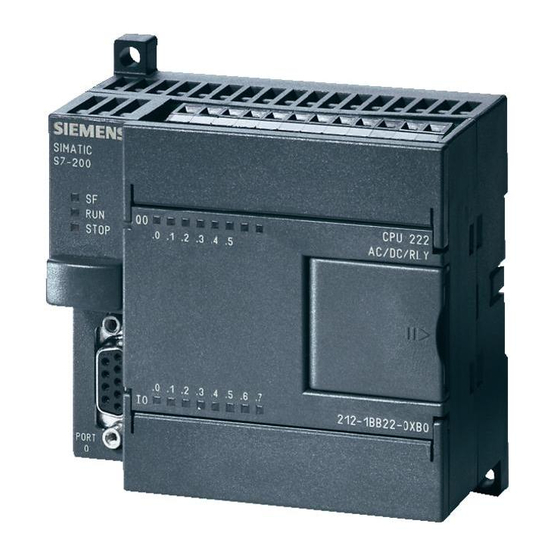
SF/DIAG Mode Switch Analog Adjustment 212-1BB23-0XB0 An.analog adjustment.is.available.to.increase.or.decrease. values.stored.in.special.memory..This.can.allow.a.variable.in.the. user.program.to.change.as.the.analog.adjustment.is.changed.. CPU.22.and.CPU.222.models.have.one.analog.adjustment.. CPU.224,.CPU.224XP ,.CPU.224.XPsi,.and.CPU.226.have.two. analog.adjustments. CPU Status Indicators. The.CPU status indicators.display.the.current.CPU.mode.. When.the.CPU.is.in.the.RUN.mode,.the.green.RUN indicator. is.lit..When.the.CPU.is.in.the.STOP.mode,.the.yellow.STOP indicator.is.lit..The.System Fault/Diagnostic (SF/DIAG) indicator.turns.red.for.a.system.fault.and.yellow.to.indicate. certain.diagnostic.conditions. I A G S F / D CPU Status Indicators The.I/O status indicators.represent.the.on.or.off.status.of. corresponding.inputs.and.outputs..For.example,.when.the.CPU. -
Page 25
Optional Cartridges S7-200.CPUs.support.an.optional.memory cartridge.that. provides.portable.EEPROM.storage.for.the.user.program..The. cartridge.can.be.used.to.copy.a.program.from.one.S7-200.PLC. to.a.like.S7-200.PLC…Two.memory.cartridge.sizes.are.available,. 64k.and.256k.bytes. Two.other.cartridges.are.also.available..A.real-time clock with battery.is.available.for.use.on.the.CPU.22.and.CPU.222..(CPU. 224,.CPU.224XP ,.CPU.224XPsi,.and.CPU.226.have.a.real-time. clock.built.in.)..The.battery.provides.up.to.200.days.of.data. retention.time.in.the.event.of.a.power.loss..Another.cartridge.is. available.with.a.back-up battery only. S F/ D IA G… -
Page 26
Inputs and Outputs Input.devices,.such.as.switches,.pushbuttons,.and.other. sensors.are.connected.to.the.terminal.strip.under.the.bottom. cover.of.the.PLC. Output Devices Local Output Points SF/DIAG SF/DIAG Local Input Points Input Simulator Input Devices A.convenient.method.of.testing.a.program.is.to.wire.toggle. switches.to.the.inputs..Input simulators.with.pre-wired.toggle. switches.are.available.for.use.with.S7-200.PLCs..Switches.are. wired.between.the.24.VDC.power.supply.(L+).and.the.inputs.. For.example,.the.switch.on.the.far.left.is.wired.between.the. first.input.(0.0).and.L+..When.the.switch.is.closed,.24.VDC.is. applied.to.the.input..When.the.switch.is.open,.0.VDC.is.applied. to.the.input.. Output.devices,.such.as.relays,.are.connected.to.the.terminal. strip.under.the.top.cover.of.the.PLC..When.testing.a.program,. it.is.not.necessary.to.connect.output.devices..The.LED.status. indicators.signal.if.an.output.is.active. -
Page 27
An.optional.fan-out connector.allows.field.wiring.connections. to.remain.fixed.when.removing.or.replacing.a.CPU.22.or. CPU.222..The.appropriate.connector.slides.into.either.the.input,. output,.or.expansion.module.terminals. Field Wiring Optional Fan-out Connector for CPU 221 or CPU 222 Connector Posts CPU 224, CPU 224XP, and CPU 226 Removeable Terminal Strip CPU.224,.CPU.224XP ,.CPU.224XPsi,.and.CPU.226.do.not.have. an.optional.fan-out.connector..Instead,.their.terminal.strips.are. removable.. Super Capacitor. A.super capacitor,.so.named.because.of.its.ability.to.maintain a.charge.for.a.long.period.of.time,.protects.data.stored.in.RAM. in.the.event.of.a.power.loss.. The.RAM.memory.is.typically.backed.up.for.50.hours.on.the. CPU.22.and.CPU.222.and.for.00.hours.on.the.CPU.224,.CPU. 224.XP ,.CPU.224.XPsi,.and.CPU.226.. -
Page 28
Expansion Modules. S7-200.PLCs.are.expandable.by.adding.expansion.modules.. Expansion modules.with.inputs.and/or.outputs.are.connected. to.the.base.unit.using.a.ribbon.connector.. SF/DIAG The.ribbon.connector.is.protected.by.a.cover.on.the.base.unit.. Side-by-side.mounting.completely.encloses.and.protects.the. ribbon.connector. SF/DIAG Mounting. S7-200.PLCs.can.be.mounted.in.one.of.two.ways..A.DIN.clip. allows.installation.on.a.standard.DIN rail..The.DIN.clip.snaps. open.to.allow.installation.and.snaps.closed.to.secure.the. unit.on.the.rail..The.S7-200.can.also.be.panel.mounted.using. installation.holes.located.behind.the.access.covers. Din Rail… -
Page 29
Available Expansion. Most.S7-200.expansion.modules.are.designed.to.provide. additional.I/O..However,.several.expansion.modules.are.available. to.support.communication.options,.positioning,.and.weighing. (SIWAREX.MS). CPU.22.comes.with.6.discrete.inputs.and.4.discrete.outputs. and.does.not.accept.expansion.modules. CPU.222.comes.with.8.discrete.inputs.and.6.discrete.outputs. and.accepts.up.to.2.expansion.modules. CPU.224,.CPU.224XP ,.and.CPU.224XPsi.come.with.4.discrete. inputs.and.0.discrete.outputs.and.accept.up.to.7.expansion. modules..Note:.The.digital.outputs.for.the.CPU.224XPsi.are. current.sinking. CPU.226..comes.with.24.discrete.inputs.and.6.discrete. outputs.and.accepts.up.to.7.expansion.modules. 6 Inputs, 4 O utputs C P U 221 N o E xpansion M odules (E M ) 8 Inputs, 6 O utputs C P U 222 U p to 2 E xpansion M odules 14 Inputs, 10 O utputs… -
Page 30
I/O Numbering S7-200.inputs.and.outputs.are.labeled.at.the.wiring.terminations. and.next.to.the.status.indicators..These.alphanumeric.symbols. identify.the.I/O.address.to.which.a.device.is.connected..This. address.is.used.by.the.CPU.to.determine.which.input.is.present. and.which.output.needs.to.be.turned.on.or.off. I.designates.a.discrete.input.and.Q.designates.a.discrete. output..The.first.number.identifies.the.byte,.the.second.number. identifies.the.bit. Image.register.space.for.digital.I/O.is.always.reserved.in. increments.of.eight.bits.(one.byte)..If.a.module.does.not. provide.a.physical.point.for.each.bit.of.each.reserved.byte,. these.unused.bits.cannot.be.assigned.to.subsequent.modules. in.the.I/O.chain. Each.analog.I/O.point.is.associated.with.a.6-bit.word.in.the. S7-200.PLC.and.is.identified.by.AI.(for.analog.input).or.AQ. (for.analog.output).followed.by.a.W.(representing.a.word.of. memory).and.a.starting.byte.number..Analog.I/O.words.start.on. even-numbered.bytes.(such.as.0,.2,.or.4). Analog.I/O.points.are.always.allocated.in.increments.of.two. points..If.a.module.does.not.provide.physical.I/O.for.each.of. these.points,.these.I/O.points.are.lost.and.are.not.available.for. assignment.to.subsequent.modules.in.the.I/O.chain. The.following.example.shows.the.addressing.for.one.sample. application. CPU 224XP Module 0 Module 1 Module 2 Module 3 Module 4 14 D iscrete In 10 D iscrete O ut 2 A nalog In 1 A nalog O ut 4 D iscrete In… -
Page 31
SIMATIC Micro Panels Siemens.offers.a.variety.of.SIMATIC.Micro.Panels.designed.for. use.with.S7-200.PLCs..These.panels.provide.easy.to.implement. solutions.for.a.variety.of.display.needs. SIMATIC PANEL ENTER TD 100C TD200 SHIFT ESC ENTER TD 200 and TD 200C TP 177micro TD400C Simatic OP 73micro Value 49 HELP Tank 3 SHIFT ENTER SHIFT ENTER OP 73micro TD 400C Text.display.TD 100C.provides.a.4-line.display.with.up.to.6. -
Page 32
Reference Manual. The.SIMATIC S7-200 Programmable Controller System Manual.provides.complete.information.on.installing.and. programming.the.S7-200.PLCs..This.manual.can.be.downloaded. as.a.PDF.file.from.the.Technical Info.link.on.the.Siemens. S7-S00.web.site: .http://www.automation.siemens.com/_en/s7-200/index.htm Preface, Contents Product Overview Getting Started SIMATIC Installing the S7-200 PLC Concepts S7-200 Programming Concepts, Programmable Controller Conventions and Features System Manual S7-200 Instruction Set Communicating over a Network… -
Page 33
Review 3 The.six.models.of.S7-200.are._____.,._____.,._____.,. _____,._____,.and._____.. 2.. Which.of.the.following.is.not.available.for.an.CPU.22? a… Mode.Switch b… Expansion.Module c… Programming.Port d… Status.Indicators 3.. A.CPU.222.can.have.a.maximum.of___.expansion. modules.and.a.CPU.224.can.have.a.maximum.of.___. expansion.modules. 4.. A.CPU.222.DC/DC/DC.has.___.DC.inputs.and.___.DC. outputs.without.expansion.modules. 5.. A.CPU.224.DC/DC/DC.has.___.DC.inputs.and.___.DC. outputs.without.expansion.modules. 6.. The.fourth.output.of.an.S7-200.would.be.labeled. ______.. 7 .. S7-200.can.be.panel.mounted.or.installed.on.a.______. rail. -
Page 34: Programming.a.plc
Programming a PLC STEP 7-Micro/WIN32 . STEP 7-Micro/WIN.is.the.software.used.with.the.S7-200.PLC. to.create.a.user.program..STEP.7-Micro/WIN.programs.consist. of.a.number.of.instructions.that.must.be.arranged.in.a.logical. order.to.obtain.the.desired.PLC.operation. STEP.7-MicroWIN.programming.software.can.be.run.off.line. or.online..Off-line programming.allows.the.user.to.edit.the. program.and.perform.a.number.of.maintenance.tasks..The.PLC. does.not.need.to.be.connected.to.the.programming.device.in. this.mode. Online programming.requires.the.PLC.to.be.connected.to. the.programming.device..In.this.mode,.program.changes.are. downloaded.to.the.PLC..In.addition,.status.of.the.input/output. elements.can.be.monitored..The.CPU.can.be.started,.stopped,. or.reset… S7-200.PLCs.have.two.instruction.sets,.SIMATIC.and. IEC 1131-3..The.SIMATIC.instruction.set.was.developed.by. Siemens.prior.to.the.adoption.of.the.IEC.3-3.standard..The. IEC.3-3.instruction.set.was.adopted.by.the.International. Electrotechnical.Commission.(IEC).to.provide.a.common. approach.for.PLC.programming..The.IEC.3-3.instruction.set. is.often.preferred.by.users.who.work.with.PLCs.from.multiple. suppliers.
-
Page 35
STEP.7-Micro/WIN.has.three.editors.for.program.development,. one.for.each.of.the.types.of.programming.available,.ladder.logic. (LAD),.statement.list.(STL),.and.function.block.diagram.(FBD).. The.STL.editor.is.often.preferred.by.experienced.programmers. because.of.the.similarity.of.STL.programs.to.assembly. language.computer.programs..However,.the.STL.editor.can.only. be.used.with.the.SIMATIC.instruction.set..Both.the.LAD.and. FBD.editors.can.be.used.with.either.instruction.set..Throughout. this.course,.although.other.instruction.types.will.occasionally.be. shown,.the.emphasis.will.be.on.SIMATIC.LAD.instructions. Basic Ladder Logic Symbols PLC.ladder.logic.consists.of.a.commonly.used.set.of.symbols. that.represent.instructions..Understanding.these.basic.symbols. is.essential.to.understanding.PLC.operation. Contacts One.of.the.most.confusing.aspects.of.PLC.programming.for. first-time.users.is.the.relationship.between.the.device.that. controls.a.status.bit.and.the.programming.function.that.uses. a.status.bit..Two.of.the.most.common.programming.functions. are.the.normally open (NO) contact.and.the.normally closed (NC) contact..Symbolically,.power.flows.through.these. contacts.when.they.are.closed..The.normally.open.contact.(NO). is.closed.when.the.input.or.output.status.bit.controlling.the. contact.is…The.normally.closed.contact.(NC).is.closed.when. the.input.or.output.status.bit.controlling.the.contact.is.0. Coils. Coils.represent.relays.that.are.energized.when.power.flows. to.them..When.a.coil.is.energized,.it.causes.a.corresponding. output.to.turn.on.by.changing.the.state.of.the.status.bit. controlling.that.output.to…That.same.output.status.bit.may.be. used.to.control.normally.open.and.normally.closed.contacts. elsewhere.in.the.program. -
Page 36
Boxes. Boxes.represent.various.instructions.or.functions.that.are. executed.when.power.flows.to.the.box..Typical.box.functions. include.timers,.counters,.and.math.operations. Entering Elements. Control elements.are.entered.in.the.ladder.diagram.by. positioning.the.cursor.and.selecting.the.element.from.a.list.. In.the.following.example.the.cursor.has.been.placed.in.the. position.to.the.right.of.I0.2..A.coil.was.selected.from.a.pull- down.list.and.inserted.in.this.position. Network 1 I0.0 I0.1 Q0.0 Network 2 Cursor I0.2… -
Page 37
AND Operation. Each.rung.or.network.on.a.ladder.represents.a.logic.operation.. The.following.programming.example.demonstrates.an.AND operation..Two.contact.closures.and.one.output.coil.are.placed. on.network…They.are.assigned.addresses.I0.0,.I0.,.and.Q0.0.. Note.that.in.the.statement.list.a.new.logic.operation.always. begins.with.a.load.instruction.(LD)..In.this.example.I0.0.(input.). and.(A.in.the.statement.list).I0..(input.2).must.be.true.in.order. for.output.Q0.0.(output.).to.be.true..This.same.logic.is.also. shown.in.a.function.block.diagram.. The.following.truth.table.represents.the.state.of.the.output.for. each.combination.of.input.states. I0.0 I0.1 Q0.0… -
Page 38
OR Operation. In.this.example,.an.OR operation.is.used.in.network…In.the. following.example,.if.either.input.I0.2.(input.3).or.(O.in.the. statement.list).input.I0.3.(input.4),.or.both.are.true,.then.output. Q0..(output.2).is.true.. The.following.truth.table.represents.the.state.of.the.output.for. each.combination.of.input.states. I0.2 I0.3 Q0 .1… -
Page 39
Testing a Program. Once.a.program.has.been.written,.it.needs.to.be.tested.and. debugged..One.way.this.can.be.done.is.to.simulate.the.field. inputs.with.an.input.simulator,.such.as.the.one.made.for.the. S7-200.PLC.. The.program.is.first.downloaded.from.the.programming.device. to.the.CPU..The.selector.switch.is.placed.in.the.RUN.position.. The.simulator.switches.are.operated.and.the.resulting.indication. is.observed.on.the.output.status.indicator.lamps. SF/DIAG Input Simulator Contact and Coil Status After.a.program.has.been.loaded.and.is.running.in.the.PLC,.the. actual.status.of.ladder.elements.can.be.monitored.using.STEP.7. Micro/WIN.software.. For.example,.in.the.following.illustration,.the.toggle.switch. controls.the.status.bit.for.I2…As.long.as.the.toggle.switch.is. open,.the.I2..status.bit.is.a.logic.0..The.I2..status.bit.controls. the.I2..normally.open.contact..Because.the.I2..status.bit.is. a.logic.0,.the.normally.open.contact.function.is.open.and.no. power.is.passed.to.the.Q3..coil.function..As.a.result,.the.Q3.. status.bit.remains.a.logic.0.and.output.point.Q3..is.off. CPU Program Toggle Switch I2.1 Q3.1 Input Input Output Output Point Status Bit Status Bit Point I2.1… -
Page 40
When.the.toggle.switch.closes,.input.point.I2..turns.on.and. I2..status.bit.changes.to.a.logic…This.causes.normally.open. contact.I2..to.close.and.turn.on.Q3..coil..Note.that.a.closed. contact.and.a.coil.that.is.on.are.shown.highlighted.in.the. program..When.Q3..coil.turns.on,.the.Q3..status.bit.goes.to.a. logic..and.output.point.Q3..turns.on..This.causes.the.lamp.to. light. CPU Program Toggle Switch I2.1 Q3.1 Input Input Output Output Point Status Bit Status Bit Point I2.1 I2.1 Q3.1 Q3.1 Lamp Logic 1 Logic 1 Forcing. Forcing.is.another.useful.tool.in.the.startup.and.maintenance. of.a.PLC.system..Forcing.overrides.one.or.more.input.or.output. status.bits,.causing.them.to.stay.in.either.a.logic.0.or.logic.. status.. For.example,.in.the.following.illustration,.the.toggle.switch.is. open..Under.normal.circumstances,.the.toggle.switch.would. have.to.be.closed.to.turn.on.the.lamp..However,.if.the.I2.. status.bit.is.forced.to.a.logic.,.the.lamp.will.turn.on,.as.long.as. -
Page 41
The.following.table.shows.the.appearance.of.ladder.diagram. elements.with.associated.status.bits.in.the.on,.off,.forced.on,. and.forced.off.conditions. -
Page 42: Discrete.inputs/Outputs
Discrete Inputs/Outputs Motor Starter Example. While.the.lamp.application.previously.discussed.is.useful.to. explain.basic.PLC.operation,.a.more.practical,.and.only.slightly. more.complex,.application.is.start-stop.control.of.an.AC.motor.. Before.examining.the.PLC.application,.first.consider.a.hard- wired.approach.. The.following.line.diagram.illustrates.how.a.normally.open.and. a.normally.closed.pushbutton.might.be.connected.to.control. a.three-phase.AC.motor..In.this.example,.a.motor.starter.coil. (M).is.wired.in.series.with.a.normally.open,.momentary.Start. pushbutton,.a.normally.closed,.momentary.Stop.pushbutton,. and.normally.closed.overload.relay.(OL).contacts. Type/T ipo Frame- EG 100 Amp Circuit Breaker Contactor Overload Relay Motor Start Pushbutton Stop Pushbutton Starter Coil Auxiliary Contact (Holding Circuit) Momentarily.pressing.the.Start.pushbutton.completes.the.path. for.current.flow.and.energizes.the.motor.starter.(M)..This.closes. the.associated.M.and.Ma.(auxiliary.contact.located.in.the.motor.
-
Page 43
The.motor.will.run.until.the.normally.closed.Stop.button. is.pressed,.unless.the.overload.relay.(OL).contacts.open.. When.the.Stop.button.is.pressed,.the.path.for.current.flow.is. interrupted,.opening.the.associated.M.and.Ma.contacts,.and. the.motor.stops. PLC Motor Control. This.motor.control.application.can.also.be.accomplished. with.a.PLC..In.the.following.example,.a.normally.open.Start. pushbutton.is.wired.to.the.first.input.(I0.0),.a.normally.closed. Stop.pushbutton.is.wired.to.the.second.input.(I0.),.and. normally.closed.overload.relay.contacts.(part.of.the.motor. starter).are.connected.to.the.third.input.(I0.2)..These.inputs.are. used.to.control.normally.open.contacts.in.a.line.of.ladder.logic. programmed.into.the.PLC.. SF/D IAG CPU Program Start (NO) Input Output Points Point Network 1 I0.0 Q0.0 I0.0 I0.1 I0.2 Q0.0 Stop (NC) Motor Starter Motor I0.1 Q0.0 I0.2 Initially,.I0..status.bit.is.a.logic..because.the.normally.closed. -
Page 44
Program Operation. When.the.Start.pushbutton.is.pressed,.the.CPU.receives.a.logic. .from.input.I0.0..This.causes.the.I0.0.contact.to.close..All.three. inputs.are.now.a.logic…The.CPU.sends.a.logic..to.output. Q0.0..The.motor.starter.is.energized.and.the.motor.starts. CPU Program Start (NO) Input Output Points Point Motor Network 1 I0.0 Q0.0 Starts I0.0 I0.1 I0.2 Q0.0 Stop (NC) Motor Starter Motor I0.1 Q0.0 I0.2 The.output.status.bit.for.Q0.0.is.now.a…On.the.next.scan,. when.normally.open.contact.Q0.0.is.solved,.the.contact.will. close.and.output.Q0.0.will.stay.on.even.if.the.Start.pushbutton. is.released. CPU Program Start (NO) Input Output Points… -
Page 45
Adding Run and Stop. The.application.can.be.easily.expanded.to.include.indicator Indicator Lights. lights.for.run.and.stop.conditions..In.this.example,.a.RUN. indicator.light.is.connected.to.output.Q0..and.a.STOP.indicator. light.is.connected.to.output.Q0.2. The.ladder.logic.for.this.application.includes.normally.open. Q0.0.contact.connected.on.Network.2.to.output.coil.Q0.. and.normally.closed.Q0.0.contact.connected.on.Network.3. to.output.coil.Q0.2..When.Q0.0.is.off,.the.normally.open.Q0.0. contact.on.Network.2.is.open.and.the.RUN.indicator.off..At.the. same.time,.the.normally.closed.Q0.0.contact.is.closed.and.the. STOP.indicator.is.on. Start (NO) Input CPU Program Output Points Points Network 1 I0.0 Motor is Q0.0 I0.0 I0.1 I0.2 Q0.0 Stopped Stop (NC) Motor Starter Motor I0.1 Q0.0… -
Page 46
Adding a Limit Switch. The.application.can.be.further.expanded.by.adding.a.limit. switch..The.limit.switch.could.be.used.in.this.application.for.a. variety.of.functions..For.example,.the.limit.switch.could.be.used. to.stop.the.motor.or.prevent.the.motor.from.being.started.. In.this.example,.the.limit.switch.is.associated.with.an.access. door.to.the.motor.or.its.associated.equipment..The.limit.switch. is.connected.to.input.I0.3.and.controls.a.normally.open.contact. in.the.program..If.the.access.door.is.open,.limit.switch.LS.is. open.and.normally.open.contact.I0.3.is.also.open..This.prevents. the.motor.from.starting. Start (NO) Input CPU Program Output Points Points Network 1 Motor is I0.0 Q0.0 I0.0 I0.1 I0.2 I0.3 Q0.0 Stopped Stop (NC) Motor Starter I0.1 Motor Q0.0 With I0.3 Contact Open, Motor will not Start… -
Page 47
Further Expansion. The.PLC.program.can.be.further.expanded.to.accommodate.a. wide.variety.of.commercial.and.industrial.applications. Start/Stop.pushbuttons,.selector.switches,.indicator.lights,.and. signaling.columns.can.be.added..Motor.starters.can.be.added. for.control.of.additional.motors..Over-travel.limit.switches.can. be.added.along.with.proximity.switches.for.sensing.object. position..Various.types.of.relays.can.be.added.to.expand.the. variety.of.devices.being.controlled. As.needed,.expansion.modules.can.be.added.to.further. increase.the.I/O.capability..The.applications.are.only.limited.by. the.number.of.I/Os.and.amount.of.memory.available.for.the. PLC. Signaling Indicator Lights Relays Motor Starters Column Discrete Ouputs SF/DIAG Expansion Module Discrete Inputs Selector Pushbuttons Limit Switches Proximity Switches Switch… -
Page 48
Review 4 Identify.the.following.symbols: a. ____________ b. ____________ c. ____________ 2.. Complete.the.following.tables: AND Function OR Function Input 1 Input 1 Input 2 Output Input 2 Output a. ___ e. ___ b. ___ f. ___ c. ___ g. ___ d. ___ h. ___ 3.. -
Page 49: Analog.inputs.and.outputs
Analog Inputs and Outputs Many.PLCs.also.work.with.analog.I/O.devices..Analog.devices. use.signals.that.are.continuously.variable.within.a.specified. range,.such.as.0.to.0.VDC.or.4.to.20.mA. Analog.signals.are.used.to.represent.variable.values,.such.as. speed,.rate.of.flow,.temperature,.weight,.level,.etc..In.order.to. process.an.input.of.this.type,.a.PLC.must.convert.the.analog. signal.to.a.digital.value..S7-200.PLCs.convert.each.analog. voltage.or.current.value.into.a.2-bit.digital.value. Digital.values.from.analog.inputs.are.stored.in.addressable. memory.for.use.by.the.user.program..Similarly,.the.user. program.can.place.digital.values.in.addressable.memory. locations.for.conversion.to.analog.values.for.the.designated. analog.outputs. The.only.S7-200.CPU.model.with.analog.I/O.points.on.board. is.CPU.224XP ,.which.has.2.analog.inputs.and..analog.output.. However,.analog.I/O.points.can.be.added.using.expansion. modules.for.any.CPU.other.than.CPU.22..CPU.222.allows. for.2.expansion.modules.and.the.remaining.CPUs.allow.for.7. expansion.modules. Expansion.modules.are.available.with.4.or.8.analog.inputs,. 2.or.4.analog.outputs,.or.4.analog.inputs.and..analog. output..In.addition,.expansion.modules.are..available.for.use. with.thermocouples.or.RTD.type.sensors.which.sense.the. temperature.at.a.specific.point.in.a.machine.or.process.. SF/DIAG Analog Expansion Module…
-
Page 50
Analog Input Example. Analog.inputs.can.be.used.for.a.variety.of.purposes..In.the. following.example,.a.scale.is.connected.to.a.load.cell..A.load. cell.is.a.device.that.generates.an.electrical.output.proportional. to.the.force.applied. Package Route Controled by PLC Scale Inspection Station Finished Goods Inventory 0 to 10 VDC Analog Signal to PLC Desired Weight = 25 LBS = 5 VDC The.load.cell.in.this.example.converts.a.value.of.weight.from.0. to.50.pounds.into.a.0.-.0.VDC.analog.value..The.0.-.0.VDC.load. cell.signal.is.connected.to.an.S7-200.PLC’s.analog.input. The.analog.value.applied.to.the.PLC.can.be.used.in.various. ways..For.instance,.the.actual.weight.can.be.compared.to.a. desired.weight.for.a.package..Then,.as.the.package.is.moved. on.a.conveyor,..the.S7-200.PLC.can.control.a.gate.to.direct. -
Page 51
Analog Output Example. Analog.outputs.from.a.PLC.are.often.supplied.directly.or. through.signal.converters.or.transmitters.to.control.valves,. instruments,.electronic.drives.or.other.control.devices.which. respond.to.analog.signals. For.example,.analog.outputs.from.the.PLC.could.be.used.to. control.the.flow.of.fluid.in.a.process.by.controlling.AC.drives.. Rather.than.simply.turning.the.AC.drives.on.or.off,.which.could. be.accomplished.by.discrete.outputs,.analog.signals.can.be. used.to.control.the.output.of.the.AC.drives…This.would.allow. the.speed.of.the.pumps.to.be.varied.dynamically.in.response.to. changes.in.process.requirements. AC Drives To Pump 1 Central Signal from Analog Processing Analog Level Transmitter Input Unit Outputs (CPU) To Pump 2 Process Level Transmitter Storage Tank Pump 1 Pump 2… -
Page 52: Timers
Timers In.a.PLC,.timers.are.programming.functions.that.keep.track. of.time.and.allow.PLC.programs.to.provide.varied.responses. depending.on.the.elapsed.time. Hard-wired Timing Circuit. Timers.in.a.PLC.program.can.be.compared.to.hard-wired.timing. circuits,.such.as.the.one.represented.in.the.accompanying. control.line.diagram..In.this.example,.normally.open.(NO).switch. (S).is.used.with.timer.(TR)..When.S.closes,.TR.begins. timing..When.the.timer’s.preset.time.elapses,.TR.closes.its. associated.normally.open.TR.contact.and.pilot.light.PL.turns. on..When.S.opens,.TR.de-energizes.immediately,.the.TR. contact.opens,.and.PL.turns.off.. Closes a preset time after S1 closes This.type.of.timer.is.referred.to.as.an.on-delay.timer..The.term. “on-delay”.indicates.that.the.timing.begins.when.the.timer. receives.a.signal.to.turn.on..In.this.example,.that.happens.when. S.closes.
-
Page 53
S7-200 SIMATIC Timers. The.S7-200.SIMATIC.LAD.instruction.set.includes.three.types. of.timers:.On-Delay.Timer.(TON),.Retentive.On-Delay.Timer. (TONR),.and.Off-Delay.Timer.(TOF)..Timers.are.represented.in.an. S7-PLC.ladder.logic.program.by.boxes. S7-200.timers.have.a.resolution.of..millisecond,. 0.milliseconds,.or.00.milliseconds..This.resolution.appears. in.the.lower.right.corner.of.the.timer.box..As.shown.in.the. following.illustration,.the.resolution.and.type.of.timer.that.can. be.used.depends.on.the.timer.number..The.maximum.value.of. time.shown.is.for.a.single.timer..By.adding.program.elements,. greater.time.intervals.can.be.timed. SIMATIC Timers Timer Number (T0 to T255) Txxx Txxx Txxx TONR xxx ms xxx ms xxx ms Retentive On-Delay Timer Off-Delay Timer On-Delay Timer Timer Resolution 1 ms, 10 ms, or 100 ms Timer Type Timer Number… -
Page 54
In.the.following.timer.example,.when.input.I0.3.turns.on,.the. I0.3.contact.closes,.and.timer.T37.begins.timing..T37.has.a.time. base.of.00.ms.(0..seconds)..The.preset.time.(PT).value.has. been.set.to.50..Because.the.resolution.of.the.timer.is.set.to. 00.ms,.a.preset.value.of.50.is.equal.to.5.seconds.(50.x.00. ms)..Therefore,.5.seconds.after.the.I0.3.contact.closes,.timer. bit.T37.becomes.a.logic.,.the.T37.contact.closes,.and.output. coil.Q0..and.its.associated.output.point.turn.on. If.the.switch.opens.before.5.seconds.has.elapsed,.the. accumulate.time.resets.to.0..Because.this.type.of.timer.does. not.retain.its.accumulated.time.when.its.input.(IN).goes.to.logic. 0,.it.is.said.to.be.non-retentive. Network 1 I0.3 100 ms +150 Preset time = 150 x 100 ms = 15 seconds Network 2 Q0.1… -
Page 55
SIMATIC Retentive On-Delay The.SIMATIC Retentive On-Delay Timer (TONR) functions.in. Timer (TONR). a.similar.manner.to.the.On-Delay.Timer.(TON)..Just.like.the.On- Delay.timer.(TON),.the.Retentive.On-Delay.Timer.(TONR).times. when.the.enabling.input.(IN).is.on..However,.the.Retentive.On- Delay.Timer.(TONR).does.not.reset.when.the.input.(IN).turns.off.. Instead,.the.timer.must.be.reset.with.a.Reset.(R).instruction. The.following.example.shows.a.Retentive.On-Delay.timer. (TONR).with.a.resolution.of.00.ms.and.preset.value.of.50.(5. seconds)..When.input.I0.3.turns.on,.I0.3.contact.closes,.and. timer.T5.begins.timing..If,.for.example,.after.0.seconds.input. I0.3.turns.off,.the.timer.stops..When.input.I0.3.turns.on.again,. the.timer.begins.timing.at.0.seconds..Timer.bit.T5.turns.on.5. seconds.after.input.I0.3.closes.for.the.second.time..When.timer. bit.T5.turns.on,.contact.T5.closes,.and.output.Q0..turns.on. The.Reset.(R).function,.shown.in.network.,.is.necessary.to. reset.the.accumulated.time.of.the.Retentive.On-delay.Timer. (TONR).to.zero..In.this.example,.the.Reset.(R).function.turns.on. and.resets.the.timer.when.contact.I0.2.closes..This.causes.the. T5.contact.to.open.and.output.Q0..to.turn.off. Network 1 I0.2 Network 2 I0.3 TONR 100 ms +150 Network 3 Q0.1… -
Page 56
SIMATIC Off-Delay Timer The.SIMATIC Off-Delay Timer (TOF).begins.timing.when.input (TOF) (IN).turns.off..In.the.following.example,.when.contact.I.4. closes,.the.current.value.of.timer.T33.is.set.to.0,.timer.bit.T33. turns.on.immediately,.closing.the.T33.contact,.and.turning.on. output.Q2.3. When.contact.I.4.opens,.the.timer.times.until.the.preset.time. elapses,.200.ms.in.this.example..Then,.timer.bit.T33.turns.off,. contact.T33.opens,.and.output.Q2.3.turns.off. If.the.I.4.contact.had.closed.again.before.the.200.ms.preset. time.had.elapsed,.the.timer’s.current.value.would.again.be.set. to.0,.timer.bit.T33.would.remain.on,.contact.T33.would.remain. closed,.and.output.Q2.3.would.remain.on. Network 1 I1.4 10 ms Preset time = 20 x 10 ms = 200 ms Network 2 Q2.3… -
Page 57
IEC 1131-3 Timers It.is.not.the.intent.of.this.course.to.cover.all.S7-200.instructions,. but.timer.instructions.provide.an.opportunity.to.understand. some.of.the.differences.between.the.SIMATIC.and.IEC.3-3. instruction.sets. The.timers.previously.discussed.were.SIMATIC.timers.. The.IEC 1131-3 instruction set.also.includes.three.timers,. On-Delay Timer (TON),.Off-Delay Timer (TOF),.and.Pulse Timer (TP)..The.same.three.resolutions.(.ms,.0,.ms,.and.00. ms).are.available.as.for.the.SIMATIC.timers,.and.the.resolution. is.determined.by.the.timer.number.as.shown.in.the.following. illustration. IEC 1131-3 Timers Timer Number (T0 to T255) %Txxx %Txxx %Txxx xxx ms xxx ms xxx ms On-Delay Timer Off-Delay Timer Pulse Timer Resolution… -
Page 58
Review 5 CPU.________.has.two.analog.inputs.and.one.analog. output.on-board. 2.. Three.types.of.SIMATIC.timers.available.in.the.S7-200. instruction.set.are._____________,._____________,.and. _____________. 3.. The.maximum.time.value.for.a.00.millisecond.time. base.timer.is.____________.seconds. 4.. Which.SIMATIC.Timer.requires.a.Reset.instruction? 5.. Three.types.of.IEC.3-3.timers.available.in.the.S7-200. instruction.set.are._____________,._____________,.and. _____________. -
Page 59: Counters
Counters Just.like.mechanical.counters,.PLC.counter.instructions.keep. track.of.events..As.it.counts,.a.counter.instruction.compares.an. accumulated.count.value.to.a.preset.value.to.determine.when. the.desired.count.has.been.reached..Counters.can.be.used.to. start.an.operation.when.a.count.is.reached.or.to.prevent.an. operation.from.occurring.until.a.count.has.been.reached. S7-200 SIMATIC Counters. The.S7-200.SIMATIC.LAD.instruction.set.includes.three.types. of.counters:.Count.Up.Counter.(CTU),.Count.Down.Counter. (CTD),.and.Count.Up/Down.Counter.(CTUD). SIMATIC Counters Timer Number (C0 to C255) Cxxx Cxxx Cxxx CTUD Count Up Counter Count Down Counter Count Up/Down Counter The.Count Up Counter (CTU).counts.up.by.one.each.time. the.count.up.(CU).input.transitions.from.off.to.on..When.the. accumulated.count.equals.the.preset.value.(PV).the.counter. bit.(not.shown).turns.on..The.counter.continues.to.count.until. the.accumulated.count.equals.the.maximum.value.(32767)..
-
Page 60
The.Count Up/Down Counter (CTUD).counts.up.by.one.each. time.the.count.up.(CU).input.transitions.from.off.to.on.and. counts.down.by.one.each.time.the.count.down.(CD).input. transitions.from.off.to.on..When.the.accumulated.count.equals. the.preset.value.(PV),.the.counter.bit.turns.on..When.the.reset. input.(R).turns.on.or.when.a.Reset.instruction.is.executed,.the. accumulated.count.resets.to.zero.and.the.counter.bit.turns.off. If.the.count.reaches.the.maximum.positive.value.(32,767),. the.next.count.up.input.sets.the.accumulated.count.to.the. maximum.negative.value.(-32,767)..Similarly,.if.the.count. reaches.the.maximum.negative.value,.the.next.down.count. sets.the.accumulated.count.to.the.maximum.positive.value. Count Up/Down Counter.. Counters.are.common.instructions.used.for.counting.a.wide (CTUD) Example . variety.of.events.such.as.parts.manufactured.or.packed,.items. processed,.machine.operations,.etc..For.example,.a.counter. might.be.used.to.keep.track.of.the.items.in.an.inventory. storage.area. In.the.following.example,.Count.Up/down.Counter.(CTUD).C48. is.reset.to.zero.when.contact.I0.2.closes..This.could.be.event. could.be.triggered.automatically.or.manually.to.indicate.that.the. associated.storage.location.is.empty. When.contact.I0.0.closes,.the.counter.counts.up.by…This. could.be.triggered.by.a.proximity.switch.sensing.that.an.item. has.been.placed.in.the.storage.location. When.contact.I0..closes,.the.counter.counts.down.by…This. could.be.triggered.by.a.proximity.switch.sensing.that.an.item. has.been.removed.from.the.storage.location. I0.0 CTUD I0.1 I0.2 +150 Q0.1… -
Page 61
In.this.example,.the.storage.location.has.50.spaces..When. the.accumulated.count.reaches.50,.the.counter.bit.turns. on,.contact.C48.closes,.and.output.Q0..turns.on..This.could. trigger.other.logic.in.the.program.to.divert.new.items.to. another.location.until.such.time.as.an.item.is.removed.from.this. location. IEC 1131-3 Counters. The.counters.previously.discussed.were.SIMATIC.counters..The. IEC.3-3.instruction.set.also.includes.three.counters..These. counters.are.similar.to.the.SIMATIC.counters,.but.there.are.a. few.differences. Each.IEC.3-3.counter.has.an.output.(Q).and.cumulative.value. (CV).in.the.counter.box. Count Up Counter (CTU).stops.counting.when.CV.equals.the. preset.value.(PV),.and.turns.on.output.Q. Except.for.the.CV.and.Q.values,.the.IEC.3-3.Count Down Counter (CTD).functions.like.the.SIMATIC.version..When.CV. equals.zero,.it.stops.counting,.and.output.Q.turns.on. Count Up/Down Counter (CTUD).stops.counting.up.when.CV. equals.PV.and.turns.on.output.QU..CTUD.stops.counting.down. when.CV.equals.zero.and.turns.on.output.QD. IEC 1131-3 Counters Timer Number (C0 to C255) Cxxx Cxxx Cxxx CTUD… -
Page 62: High-Speed.instructions
High-Speed Instructions As.discussed.earlier,.PLCs.have.a.scan.time..The.scan.time. depends.on.the.size.of.the.program,.the.number.of.I/Os,.and. the.amount.of.communication.required..However,.events.may. occur.in.an.application.that.require.a.response.from.the.PLC. sooner.than.the.scan.cycle.would.normally.permit..For.these. applications.high-speed.instructions,.such.as.those.associated. with.high-speed.counters,.can.be.used.. PLC Scan High-Speed Counters. A.high-speed counter.is.represented.by.two.boxes.in.ladder. logic..One.box.is.the.High-Speed Counter Definition (HDEF). instruction.and.the.other.box.is.the.High-Speed Counter (HSC).instruction. CPU.22.and.CPU.222.support.four.high-speed.counters. (HSC0,.HSC3,.HSC4,.HSC5)..CPU.224,.CPU.224XP ,.CPU. 224XPsi,.and.CPU.226.support.six.high-speed.counters.(HSC0,. HSC,.HSC2,.HSC3,.HSC4,.HSC5). HDEF MODE High-Speed Counter Definition High-Speed Counter…
-
Page 63
Definition Boxes and. The.High-Speed.Counter.Definition.(HDEF).instruction.assigns High-Speed Counters. the.operating.mode.to.a.specific.high-speed.counter.(HSCx).. The.mode.selection.defines.the.clock,.direction,.start,.and. reset.functions.of.the.high-speed.counter..High-speed.counters. can.be.defined.by.the.definition.box.to.operate.in.any.of.the. 2.available.modes..Not.all.counters.can.operate.in.all.of.the. available.modes,.however..Refer.to.the.S7-200.System.Manual. for.definitions.available.for.each.counter. The.High-Speed.Counter.(HSC).instruction.configures.and. controls.a.specific.high-speed.counter.based.upon.the.state.of. the.special.HSC.bits..The.N.parameter.specifies.the.high-speed. counter.number..Each.counter.has.dedicated.inputs.for.clocks,. direction.control,.reset,.and.start,.where.these.functions.are. supported.. Positioning Example. Positioning.is.one.example.of.an.application.that.may.require. use.of.a.high-speed.counter..In.the.following.illustration,.two. PLC.discrete.outputs.(one.for.forward.and.one.for.reverse). control.a.reversing.motor.starter,.which,.in.turn,.controls.a. motor. The.motor.shaft.is.connected.to.an.encoder.and.to.a.positioning. screw..A.platform.mounted.on.the.positioning.screw.moves. away.from.position.0.as.the.motor.turns.in.the.forward.direction. and.towards.position.0.as.the.motor.turns.in.the.reverse. direction..Pulses.from.the.encoder.are.connected.to.PLC.inputs. associated.with.a.high.speed.counter. 9 10 Encoder Motor Reversing Motor Starter In.this.example,.the.high-speed.counter.is.programmed.to. move.the.platform.from.position..to.position.6.and.later.to. -
Page 64
Assume,.for.example,.that.the.encoder.generates.600.pulses. per.revolution,.and.it.takes.000.motor.revolutions.to.move. the.platform.from.one.position.to.another,.moving.the.platform. from.position..to.position.6.(5.positions).takes.5000.motor. revolutions.or.30,000.encoder.pulses..In.most.practical. applications,.the.frequency.of.these.pulses.is.too.high.for.them. to.be.counted.with.inputs.that.are.not.associated.with.a.high- speed.counter.. Interrupts. S7-200.PLCs.incorporate.instructions.for.use.with.interrupts.. Interrupts.are.used.to.initiate.a.specific,.short.PLC.program. segment,.called.an.interrupt.routine,.when.an.internal.or. external.event.occurs..After.the.interrupt.routine.has.been. executed,.control.is.returned.to.the.main.program. Three.types.of.interrupts.are.supported.by.S7-200.PLCs,. communication port interrupts,.I/O interrupts,.and.time- based interrupts..Communication.port.interrupts.are.used. to.control.a.communication.port.operated.in.Freeport.mode.. I/O.interrupts.are.used.to.respond.quickly.to.high-speed.I/O. transitions,.such.as.those.associated.with.high-speed.counters. or.pulse.train.outputs..Time-based.interrupts.allow.the.user. program.to.execute.an.interrupt.routine.on.a.cyclic.basis. Each.of.these.types.of.interrupts.has.an.associated.priority. that.determines.which.interrupt.is.processed.first.in.the.event. that.two.or.more.interrupts.are.requested.at.the.same.time.. Communication.port.interrupts.have.the.highest.priority.and. time-based.interrupts.have.the.lowest.priority. Pulse Training Output (PTO). S7-200.PLCs.have.two.PTO/PWM generators.that.create.either. a.high-speed.pulse.train.or.a.pulse.width.modulated.waveform.. One.generator.is.assigned.to.output.point.Q0.0.and.the.other.to. output.point.Q0…When.a.generator.is.activated,.it.controls.its. respective.output. -
Page 65
The.number.of.pulses.and.the.cycle.time.can.be.changed.with. an.interrupt..In.the.accompanying.example,.each.pulse.is.initially. on.for.500.ms.and.off.for.500.ms..After.four.pulses,.an.interrupt. occurs.which.changes.the.cycle.time.to.2.seconds,..second.on. and..second.off. 1 sec 1 sec Interrupt 500 ms Occurs Pulse Width Modulation. The.Pulse Width Modulation (PWM) function.provides.a. (PWM) fixed.cycle.time.with.a.variable.duty.cycle..When.the.pulse. width.is.equal.to.the.cycle.time,.the.duty.cycle.is.00%.and.the. output.is.turned.on.continuously..In.the.following.example,.the. output.initially.has.a.0%.duty.cycle.(on.0%,.off.90%)..After.an. interrupt,.the.output.switches.to.a.50%.duty.cycle.(on.50%,.off. 50%). 10% Duty Cycle 50% Duty Cycle Interrupt Occurs The.PWM.function.can.be.used.to.provide.a.programmable. or.adjustable.control.of.machine.timing..This.allows.machine. operation.to.be.varied.to.compensate.for.product.variations.or. mechanical.wear. And Much More. -
Page 66: Specialized.expansion.modules
S7-200 PLC with Modem Computer EM 241 Modem Module The.EM.24.provides.an.international.telephone.line.interface. and.supports.sending.numeric.and.text.paging.messages,.as. well.as.SMS.(Short.Message.Service).messages.to.cellular. phones..This.is.useful.for.remote.diagnostics.and.maintenance,. machine.control,.alarm.systems,.and.general.communication. functions. In.addition.to.CPU-to-CPU.communication.via.a.telephone.line,. the.EM.24.also.supports.Modbus.RTU.protocol,.a.protocol. that.has.been.widely.used.for.many.years. SINAUT MD 720-3 SINAUT Telecontrol (Siemens Network Automation).permits GSM/GPRS Modem Module networking.of.individual.controls.and.control.systems.over.a. WAN.(Wide.Area.Network).. One.approach.for.providing.this.capability.is.SINAUT Micro.. This.is.a.simple.and.flexible.way.to.link.stationary.or.mobile. stations.to.a.master.control.center..SINAUT.Micro.is.appropriate. where.smaller.amounts.of.data.have.to.be.transmitted.to. permit.monitoring.and.control.of.remote.stations.using.wireless. techniques.with.the.General.Packet.Radio.Service.(GPRS).of.the. Global.System.for.Mobile.Communication.(GSM).mobile.radio. network..
-
Page 67
The.SINAUT MD720-3 GSM/GPRS Modem module.and. associated.ANT794-4MR antenna.are.the.hardware.elements. used.to.connect.an.S7-200.PLC.into.a.SINAUT.Micro.system.. SINAUT Micro SC software.is.also.required. WinCC flexiible, WinCC SINAUT MD720-3 720-3AA00 SINAUT MD 720-3 GSM/GPRS Modem Module Antenna CP 243-1, CP 243-1 IT Industrial.Ethernet.provides.a.proven.means.of.networking Communication Processors. computers.and.a.variety.of.intelligent.devices..CP 243-1 and CP 243-1 IT communication processors.are.used.to.connect.an. S7-200.PLC.to.an.Industrial Ethernet network. -
Page 68
EM 277 PROFIBUS-DP. PROFIBUS DP.is.an.open,.international.fieldbus.communication Module. standard.that.allows.a.broad.range.of.intelligent.devices.from. various.manufacturers.to.communicate.rapidly.and.efficiently.. This.reduces.wiring.costs.as.well.as.start-up.and.maintenance. expenses.. EM 277 PROFIBUS-DP module.allows.connection.of.the. S7-200.CPU.(CPU.222.and.above).to.a.PROFIBUS-DP.network. as.a.slave.. Other Intelligent Non-Siemens Devices and Systems S7-200 PLC with Other SIMATIC Controllers EM 277 PROFIBUS DP Module Controllers SIMATIC S7 — 200 SF/DIAG EM 277 CPU 224 .1 .2 .3 .4 .5 .6 .7… -
Page 69
EM 253 Position Module. Position.control.describes.a.range.of.applications.that.involve. movement.with.varying.degrees.of.precision..The.EM 253 Position module.is.a.simple.but.powerful.positioning.module. that.enables.the.user.to.control.position.systems.from.micro- steppers.to.intelligent.servo.drives.(with.integrated.closed-loop. control). SF/DIAG EM 253 Position ZP LMT 253-1AA22-0XA0 S7-200 PLC with EM 253 Position Module EM 253 Features. Features.of.the.module.include: •. Provides.high-speed.control.with.a.range.from.20.to.. 200,000.pulse.per.second •. Supports.both.S.curve.or.linear.acceleration.and. deceleration •. Provides.a.configurable.measuring.system.that.allows. you.to.enter.data.as.engineering.units.(such.as.inches.or. centimeters).or.as.a.number.of.pulses •. -
Page 70
Expansion Modules for Two.S7-200.PLC.expansion.modules.are.available.for.accurate Temperature Measurement temperature.measurement, EM 231 Thermocouple module and EM 231 RTD module. EM.23.Thermocouple.module.provides.analog.inputs.for. thermocouples..A.thermocouple.is.a.temperature.sensor. made.from.two.dissimilar.metals.joined.at.a.point.called.a. junction..A.thermocouple.produces.a.small.voltage.that.is. dependent.upon.temperature..Various.types.of.thermocouples. are.available.for.use.in.different.temperature.ranges..Two. versions.of.EM.23.Thermocouple.modules.are.available,.one. for.four.thermocouples.and.one.for.eight.thermocouples..Each. version.is.compatible.with.J,.K,.T,.E,.R,.S,.or.N.thermocouples,. but.the.thermocouples.used.with.a.specific.module.must.be.of. the.same.type. EM.23.RTD.module.provides.analog.inputs.for.resistance temperature detectors (RTDs)..An.RTD.is.a.temperature. sensor.made.from.a.metal,.such.as.platinum,.nickel,.or.copper,. that.varies.in.resistance.in.a.predictable.manner.as.temperature. varies..Two.versions.of.the.EM.23.RTD.module.are.available,. one.with.two.analog.inputs.and.one.with.four.analog.inputs.. Either.version.can.be.used.with.a.variety.of.RTD.types,.but.the. RTDs.used.with.a.specific.module.must.be.of.the.same.type. SIMATIC S7 — 200 SF/DIAG CPU 224 AC/DC/RLY… -
Page 71
SIWAREX MS Weighing SIWAREX MS Weighing module provides..a.simple,.easy Module to.install.approach.for.weighing.and.force.measurement. applications..SWAREX.MS.Weighing.module.is.designed.to. measure.the.voltage.produced.by.sensors.commonly.used.to. measure.weight,.force,.or.torque. SIWAREX.MS.is.easily.integrated.into.an.S7-200.PLC.system. as.an.expansion.module..This.makes.information.obtained.from. SIWAREX.MS.available.to.other.components.of.the.automation. system..In.addition,.Siemens.offers.a.wide.variety.of.compatible. sensors.and.other.components. S7-200 PLC with SIWAREX MS Module SIMATIC S7 — 200 SF/DIAG CPU 224XP .1 .2 .3 .4 .5 .6 .7 .0 .1 DC/DC/DC… -
Page 72
Review 6 Three.types.of.SIMATIC.counters.available.in.the. S7-200.instruction.set.are.____________,.____________. and.____________. 2… CPU.22.and.CPU.222.support.____.high.speed. counters..CPU.224,.CPU.224XP ,.CPU.224XPsi,.and.CPU. 226.support.____.high.speed.counters. 3.. S7-200.PLCs.have.two.___________.that.create.either. a.high-speed.pulse.train.or.a.pulse-width.modulated. waveform. 4.. ________.and.________.communication.processors. are.used.to.connect.an.S7-200.PLC.to.an.Industrial. Ethernet.network. 5.. _________.module.allows.connection.of.an.S7-200.CPU. (CPU222.and.above).to.a.PROFIBUS-DP.network.as.a. slave. 6.. _________.module.allows.connection.of.an.S7-200.CPU. (CPU222.and.above).to.an.AS-I.network.as.a.master. 7 .. Two.versions.of.EM.23.Thermocouple.module.are. available,.one.for.____.thermocouples.and.one.for.____. thermocouples. 8.. Two.versions.of.EM.23.RTD.module.are.available,.one. for.____.RTDs.and.one.for.____.RTDs. -
Page 73: Review.answers
Review Answers Review 1 ).a:.input.module,.b:.CPU,.c:.output.module,.d:.programming. device,.e:.operator.interface;.2).2;.3).6;.4).00,.000.0000,.A. Review 2. ).discrete;.2).discrete;.3).CPU;.4).Ladder.logic;.5).Statement. list,.function.block.diagrams;.6).scan;.7)024;.8).firmware; 9).RS-485. Review 3. ).CPU.22,.CPU.222,.CPU.224,.CPU.224XP ,.CPU.224XPsi,. CPU.226;.2).b;.3).2,.7;.4).8,.6;.5).4,.0;.6).Q0.3;.7).DIN. Review 4. ).a:.box,.b:.normally.open.contact,.c:.coil;. 2).AND.Function.-.a:.0,.b:.0,.c:.0,.d:.,. OR.Function.-.e:.0,.f:.,.g:.,.h:.;. 3).I0.,.I0.0,.Q0.0. Review 5. ).224XP;.2).On-Delay.Timer.(TON),.Retentive.On-Delay.Timer. (TONR),.Off-Delay.Timer.(TOF).;.3).3276.7.seconds;. 4).Retentive.On-Delay.Timer.(TONR);.5).On-Delay.Timer.(TON),. Off-Delay.Timer.(TOF),.Pulse.Timer.(TP). Review 6. ).Count.Up.Counter.(CTU),.Count.Down.Counter.(CTD),.Count. Up/Down.Counter.(CTUD);.2).4,.6;.3).PTO/PWM.generators; 4).CP.243-,.CP.243-.IT;.5).EM.277.PROFIBUS-DP 6).CP.243-2.AS-Interface.Master;.7).4,.8;.8).2,.4..
-
Page 75: Final.exam
Final Exam You.can.test.your.knowledge.by.taking.the.final.exam.for.this. course.online.at.http://www.usa.siemens.com/step..This. web.page.provides.links.to.a.variety.of.our.quickSTEP.online. courses..To.complete.the.final.exam.for.this.course,.click.on.the. Basics of PLCs.link.. Next,.move.your.mouse.over.to.the.left.so.that.the.navigation. bar.pops.out.and.select.the.Final Exam.link..The.final. exam.page.will.appear..Before.taking.the.final.exam,.it.is. recommended.that.you.delete.the.temporary.files.on.your. computer..For.most.versions.of.Internet Explorer,.you.can.do. this.by.selecting.Internet Options.from.the.Tools.menu.and. then.clicking.on.the.Delete Files.button..If.you.do.not.perform. this.step,.you.may.see.a.score.of.0%.after.you.submit.your. exam.for.grading. After.you.complete.the.final.exam,.click.on.the.Grade the Exam.button.at.the.bottom.of.the.page..Your.score.on.the.exam. will.be.displayed.along.with.the.questions.that.you.missed.. If.you.score.70%.or.better.on.the.exam,.you.will.be.given.two. options.for.displaying.and.printing.a.certificate.of.completion.. The.Print Certificate.option.allows.you.to.display.and.print.the. certificate.without.saving.your.score.in.our.database.and.the. Save Score.option.allows.you.to.save.your.score.and.display. and.print.your.certificate.
В этом разделе размещены все инструкции на оборудование Siemens (Германия) на русском, английском языке. Документы можно загрузить в формате pdf или открыть прямо на сайте.
Добавить отсутствующую инструкцию Публиковать
Поделиться ссылкой на документы с друзьями и коллегами Отправить
Документация Siemens Simatic:
Введение в STEP 7. Руководство
Программное обеспечение SIMATIC для создания программ, используемых в программируемых логических контроллерах на языках программирования контактный план, функциональный план или список операторов для станций SIMATIC S7-300/400. Основы SIMATIC STEP 7. Наиболее важные экранные диалоговые окна и процедуры, практические упражнения.
Программирование с помощью STEP 7 V5.3
Обзор программирования с помощью STEP 7.
Знакомство с продуктом и установка программного обеспечения, основы проектирования структуры программы, запуск и функционирование, сборка и редактирование проекта, определение символов, создание блоков и библиотек, логических блоков. Создание исходных файлов на STL, управление и наблюдение за переменными. Установление соединения и настройка CPU, отладка, диагностика.
SIMATIC NET NCM S7 для PROFIBUS CP
Использование коммуникационных процессоров SIMATIC NET (PROFIBUS CP) для связи по SIMATIC NET PROFIBUS на полевом уровне. Производительность и область применения коммуникационных служб. Конфигурирование CP с помощью конфигурационного программного обеспечения NCM S7. Программирование коммуникационных интерфейсов для пользовательской программы
SIMATIC NET NCM S7 для Industrial Ethernet
“PROJECT ETHERNET” Примеры STEP 7 для Ethernet CP, связь по интерфейсу SEND/RECEIVE между станциями S7. Связь по интерфейсу SEND/RECEIVE между станциями S7 и S5.
Конфигурирование аппаратуры и коммуникационных соединений STEP 7 V5.3
Обзор конфигурирования аппаратуры и проектирование соединений с помощью программного обеспечения STEP 7. Поддержка при отображении структуры аппаратного обеспечения в форме проекта STEP 7, организация обмена данными между системами автоматизации.
Первые шаги в PLC S7-200
Установка оборудования ( Монтаж). Органы управления S7-200 (CPU 212). Подключение устройства. Схема учебного устройства. Схема подключения S7-200 (CPU 212). Запуск STEP 7-Micro/WIN
Программируемый контроллер S7-200 Руководство по эксплуатации
CPU S7–200. Модули расширения S7–200. Пакет для программирования STEP 7-Micro/WIN. Возможности обмена данными. Индикаторные панели. Первые шаги. Подключение CPU S7–200. Создание программы-примера. Загрузка программы-примера
CP 243-1 Коммуникационный процессор для Industrial Ethernet
Использование коммуникационного процессора CP 243-1.Информация о том, как эксплуатировать данный коммуникационный процессор, подключенный через Industrial Ethernet (IE).
Первые шаги в PLC S7-300
Основные функции аппаратного и программного обеспечения S7–300.
Система автоматизации S7-300 Данные модулей
Общие технические данные. Источники питания. Цифровые модули. Принципы обработки аналоговых величин. Представление аналоговых величин аналоговых модулей. Аналоговые модули. Другие сигнальные модули. Интерфейсные модули. Повторитель RS 485. Наборы параметров сигнальных модулей. Диагностические данные сигнальных модулей
S7-300 CPU 31xC и CPU 31x, технические данные
Путеводитель по документации S7-300. Элементы управления и индикации. Обмен данными. Концепция памяти. Времена цикла и реакции. Общие технические данные. Технические данные CPU 31xC. Технические данные CPU31x 8.
SIMATIC S5-90U, S5-95U, S5-95F, S5-100U
Программируемый контроллер S5-95U
SIMATIC S5. Контроллер S5-100U (CPU100/CPU102). Руководство по применению.
SIMATIC S5. Контроллер SIMATIC S5-115U
Программируемые контроллеры S7-200
SIMATIC S7–200. Обзор продукта.
SIMATIC S7-300. Общие сведения. Ч1.
SIMATIC S7-300. Функциональные модули. Ч2.
S7-400. Система автоматизации S7-400. Данные CPU.
Программируемые контроллеры S7-400. Обзор.
SIMATIC S7-1200 -микроконтроллер для Totally Integrated Automation
SIMATIC S7-1500 контроллер для Totally Integrated Automation
LOGO! Руководство.
Логические модули LOGO!
Скачать документацию:
Введение в STEP 7. Руководство.
Программирование с помощью STEP 7 V5.3
SIMATIC NET NCM S7 для PROFIBUS CP
SIMATIC NET NCM S7 для Industrial Ethernet
Конфигурирование аппаратуры и коммуникационных соединений STEP 7 V5.3
Первые шаги в PLC S7-200
Программируемый контроллер S7-200 Руководство по эксплуатации
CP 243-1 Коммуникационный процессор для Industrial Ethernet
Первые шаги в PLC S7-300
Система автоматизации S7-300 Данные модулей
S7-300 CPU 31xC и CPU 31x, технические данные
SIMATIC S5-90U, S5-95U, S5-95F, S5-100U
Программируемый контроллер S5-95U
SIMATIC S5. Контроллер S5-100U (CPU100/CPU102). Руководство по применению.
SIMATIC S5. Контроллер SIMATIC S5-115U
Программируемые контроллеры S7-200
SIMATIC S7–200. Обзор продукта.
SIMATIC S7-300. Общие сведения. Ч1.
S7-400. SIMATIC S7-300. Функциональные модули. Ч2.
S7-400. Система автоматизации S7-400. Данные CPU.
Программируемые контроллеры S7-400. Обзор.
SIMATIC S7-1200 -микроконтроллер для Totally Integrated Automation
SIMATIC S7-1500 -микроконтроллер для Totally Integrated Automation
LOGO! Руководство.
Логические модули LOGO!
Программное обеспечение
S7-300 Документация. Данные модулей.
1_General_r.pdf
2_PowerSupply_r.pdf
3_Digital_r_MN.pdf
4_Analog_r_MN.pdf
5_OtherSignalModules_r.pdf
6_InterfaceModules_r.pdf
7_Repeater_r_MN.pdf
8_SIMATIC_TOP_r.pdf
GS_SM331_4-20mA_r.pdf
GS_SM331_TC_r.pdf
GS_SM331_U&PT100_r.pdf
S7-300 Документация. Данные ЦПУ.
CPU_31xC_&_CPU_31x_r.pdf
S7-300 Документация. Модуль автоматическогого регулирования FM355.
00_Preface&Contents_r_355.pdf
01_Overview_r_355.pdf
02_Settings_r.pdf
03_Work_r.pdf
04_Installing_r.pdf
05_Wiring_r.pdf
06_Assign_Parameters_r.pdf
07_User_Programm_r.pdf
08_StartingUp_r_355.pdf
09_Properties_DIO-AIO_r.pdf
10_Connecting_r.pdf
11_Assignment_DB_r.pdf
12_Faults&Diagnostics_r.pdf
13_Examples_r.pdf
Appendix_r_355.pdf
S7-300 Документация. Первые шаги.
GS_Analog_r.pdf
GS_Controlling_r.pdf
GS_Counting_r.pdf
GS_Digital_r.pdf
GS_PtP_r.pdf
S7-300 Документация. Первые шаги в пуско-наладочных работах для FM355.
get_c_r.pdf
get_s_r.pdf
S7-300 Документация. Примеры программ.
S7-300C_TF-Sample_r.pdf
S7-300 Документация Система S7-300.Руководство по инсталяции
0_Titelblatt_r.pdf
01-04_Preface_r.pdf
05_Configuring_r.pdf
06-07_Installation_r.pdf
08-09_Addressing_r.pdf
10-11_Maintenance_r.pdf
12-13-ind_Appendix_r.pdf
S7-300 Документация. Список инструкций системы S7-300.
OpList_S7-300C_r.pdf
S7-300 Документация. Технологические функции CPU 31xC.
0_Preface_Contents_r_TF.pdf
1_Overview_r.pdf
2_Positioning_r.pdf
3_Positioning_AO_r.pdf
4_Positioning_DO_r.pdf
6_Point-to-Point_r.pdf
7_Controlling_r.pdf
S7-300 Документация. Функциональный модуль FM350-1.
01_ProductOverview_r.pdf
02_HowCounts_r.pdf
04_Wiring_r.pdf
05_Assigning_Parameters_r.pdf
06_Programming_r.pdf
07_Programming_in_M7_r.pdf
08_StartingUp_r_350.pdf
09_OperatingModes_r.pdf
10_EncoderSignals_r.pdf
11_DB_Assignments_r.pdf
12_M7_Function_Library_r.pdf
13_Faults&Diagnostics_r.pdf
A_Appendix_r_350.pdf
GetStarted_FM350-1_r.pdf
S7-200 Документация S7-200 Примеры применения
Contents_r.pdf
ContentsSort_e.pdf
S72_01.pdf
S72_02.pdf
S72_03.pdf
S72_04.pdf
S72_05.pdf
S72_06.pdf
S72_07.pdf
S72_08.pdf
S72_09.pdf
S72_10.pdf
S72_11.pdf
S72_12.pdf
S72_13.pdf
S72_14.pdf
S72_15.pdf
S72_16.pdf
S72_17.pdf
S72_18.pdf
S72_19.pdf
S72_20.pdf
S72_21.pdf
S72_22.pdf
S72_23.pdf
S72_24.pdf
S72_25.pdf
S72_26.pdf
S72_27.pdf
S72_28.pdf
S72_29.pdf
S72_30.pdf
S72_31.pdf
S72_32.pdf
S72_33.pdf
S72_34.pdf
S72_35.pdf
S72_36.pdf
S72_37.pdf
S72_38.pdf
S72_39.pdf
S72_40.pdf
S72_41.pdf
S72_42.pdf
S72_43.pdf
S72_44.pdf
S72_45.pdf
S72_46.pdf
S72_47.pdf
S72_48.pdf
S72_49.pdf
S72_50.pdf
S72_51.pdf
S72_52.pdf
S72_53.pdf
S72_54.pdf
S72_55.pdf
S72_56.pdf
S72_57.pdf
Интерфейс оператора TD 200
01_Overview&Installation_r.pdf
02_Configuring_r.pdf
03_Operating_r.pdf
04_Creating_programs_r.pdf
A_Appendix_r_TD200.pdf
Titel_r.pdf
Коммуникационный модуль CP243-1
CP243-1_1ru.pdf
Коммуникационный процессор CP 243-1 IT
CP243-1it_E.pdf
Первые шаги
1steps_r.pdf
Сенсорная панель TPO70
05_TP070_r.pdf
Системное руководство СРU21x
0_Preface_r.pdf
1_Introducing_r.pdf
2_Installing_HW_r.pdf
3_Installing_SW_r.pdf
4_GettingStarted_r.pdf
5_Programming_r.pdf
6_Memory_r.pdf
7_InputOutput_r.pdf
8_Communication_r.pdf
9_Instruction_r.pdf
A_TechData_r.pdf
B_Appendix_r.pdf
Системное руководство СРU22x
0_preface.pdf
01_Owerview_r.pdf
02_GettingStarted_r.pdf
03_Installing_r.pdf
04_PLC%20Concepts_r.pdf
05_ProgrammingConcepts_r.pdf
06_InstructionSet_r.pdf
07_Communicating_r.pdf
08_TroubleShooting_r.pdf
09_PositionModule_r.pdf
10_ModemModule_r.pdf
11_USS_Protocol_r.pdf
12_ModbusProtocol_r.pdf
A_Appendix_r1.pdf
I_Index_r.pdf»
06_InstructionSet_r.pdf
10_ModemModule_r.pdf
01_Introduction_r.pdf
02_S7-200_r.pdf
03_SIPLUS_r.pdf
A_Appendix_r.pdf